Ademco 8DLPHS8-US GSM/GPRS/UMTS/HSPA Module Cartridge User Manual Info Rev E
Honeywell International Inc. GSM/GPRS/UMTS/HSPA Module Cartridge Users Manual Info Rev E
UserManual.wiki
>
Ademco
>
8DLPHS8 US User Manual
Users Manual Info Rev E
Navigation menu
Upload a User Manual
Namespaces
Wiki Guide
HTML
PDF
Info
Views
User Manual
Discussion / Help
Navigation
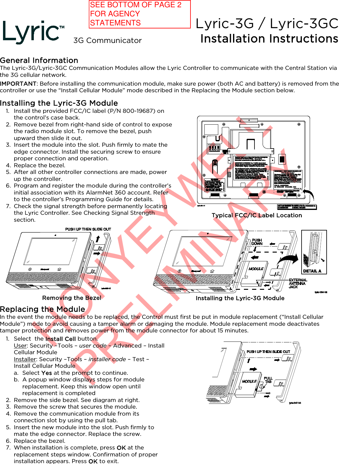
![HONYEYWELL PRELIMINARYÊ800-19181@Š 800-19181 4/15 Rev. A 2 Corporate Center Drive, Suite 100 P.O. Box 9040, Melville, NY 11747 Copyright © 2015 Honeywell International Inc. www.honeywell.com/security Checking Signal Strength When choosing a suitable mounting location, check the communicator’s signal strength to ensure proper operation. For most installations, using the module’s internal antenna, mounting the Lyric controller as high as practical, and avoiding large metal components provides adequate signal strength for proper operation. Use the Lyric Controller “Cellular Information” screen to display signal strength (in dBm): Security – Tools – [installer code] – Program – Comm. Diagnostics – Cellular Information Compare the RSCP (received signal code power [3G]) or RSSI (received signal strength indicator [2G]) number displayed to the Signal Strength Guide at right to ensure adequate signal strength. If necessary, relocate the Controller to obtain better signal strength (press Cellular Information again to refresh the reading). Signal Strength Guide RSCP (3G) – if module is using the 3G Network Good ......... -20 to -90 dBm OK ............. -91 to -100 dBm Marginal .. -101 to -106 dBm Bad ............ -107 to -120 dBm RSSI (2G) – if module is using the 2G Network Good ......... -20 to -89 dBm OK ............. -90 to -98 dBm Marginal .. -99 to -104 dBm Bad ............ -105 to -120 dBm If adequate signal strength cannot be achieved, an external antenna should be used. Use external antenna kit model Cell-ANTST.Specifications Dimensions: .... 2-5/8”W x 3-1/8”L x 1/2”D Voltage Input .. 5V (provided by the controller) Current Idle ............... 60mA, standby Transmit ..... 500mA Environmental Operating temperature: -20ºC to +55ºC, (for compliance agency: 0ºC to +49ºC) Storage temperature: -40º to +70ºC Humidity: 0 to 95% relative humidity, non-condensing (for compliance agency 0% to 85%) Frequency Bands: 2G GSM/GPRS/EDGE Quad Band 850/900/1800/1900 MHz 3G UMTS Band V, Band II 850/1900MHz WCDMA HSUPA HSDPA External Antenna Kit: Cell-ANTST SUPPORT & WARRANTY For the latest documentation and online support, please go to: https://mywebtech.honeywell.com/ For the latest warranty information, please go to: www.honeywell.com/security/hsc/resources/wa. MyWebTech Warranty RF Exposure Warning The antenna(s) used for this transmitter must be installed to provide a separation distance of at least 7.8 in (20 cm) from all persons and must not be co-located or operated in conjunction with any other transmitter except in accordance with FCC multi-transmitter product procedures. Mise en Garde Exposition aux Frequences Radio: L'antenne (s) utilisée pour cet émetteur doit être installée à une distance de séparation d'au moins 7,8 pouces (20 cm) de toutes les personnes. FEDERAL COMMUNICATIONS COMMISSION (FCC) & INDUSTRY CANADA (IC) STATEMENTS The user shall not make any changes or modifications to the equipment unless authorized by the Installation Instructions or User's Manual. Unauthorized changes or modifications could void the user's authority to operate the equipment. FCC CLASS B STATEMENT This equipment has been tested to FCC requirements and has been found acceptable for use. The FCC requires the following statement for your information: This equipment generates and uses radio frequency energy and if not installed and used properly, that is, in strict accordance with the manufacturer's instructions, may cause interference to radio and television reception. It has been type tested and found to comply with the limits for a Class B computing device in accordance with the specifications in Part 15 of FCC Rules, which are designed to provide reasonable protection against such interference in a residential installation. However, there is no guarantee that interference will not occur in a particular installation. If this equipment does cause interference to radio or television reception, which can be determined by turning the equipment off and on, the user is encouraged to try to correct the interference by one or more of the following measures: • If using an indoor antenna, have a quality outdoor antenna installed.• Reorient the receiving antenna until interference is reduced or eliminated.• Move the radio or television receiver away from the receiver/control. • Move the antenna leads away from any wire runs to the receiver/control. • Plug the receiver/control into a different outlet so that it and the radio or television receiver are on different branch circuits.• Consult the dealer or an experienced radio/TV technician for help. INDUSTRY CANADA CLASS B STATEMENT This Class B digital apparatus complies with Canadian ICES-003. Cet appareil numérique de la classe B est conforme à la norme NMB-003 du Canada. FCC / IC STATEMENT This device complies with Part 15 of the FCC Rules, and RSS-210 of IC. Operation is subject to the following two conditions: (1) This device may not cause harmful interference (2) This device must accept any interference received, including interference that may cause undesired operation. Cet appareil est conforme à la partie 15 des règles de la FCC & de RSS-210 des Industries Canada. Son fonctionnement est soumis aux conditions suivantes: (1) Cet appareil ne doit pas causer d' interférences nuisibles. (2) Cet appareil doit accepter toute interférence reçue y compris les interférences causant une réception indésirable. IMPORTANT NOTE ABOUT EXTERNAL ANTENNAS If an external cellular radio antenna is used, the antenna may be installed or replaced ONLY by a professional installer. TO THE INSTALLER For the Lyric-3G, the external antenna must not exceed a maximum directional gain (including cable loss) of 6.0 dBi at 850 MHz and 2.5 dBi at 1900 MHz.](https://usermanual.wiki/Ademco/8DLPHS8-US/User-Guide-2657002-Page-2.png)