Ademco K3852 Cellular Control Channel Transceiver User Manual K3852InstallationAnd SetupGuide
Honeywell International Inc. Cellular Control Channel Transceiver K3852InstallationAnd SetupGuide
Ademco >
Contents
- 1. Users Manual
- 2. Revised Section of Installation Manual
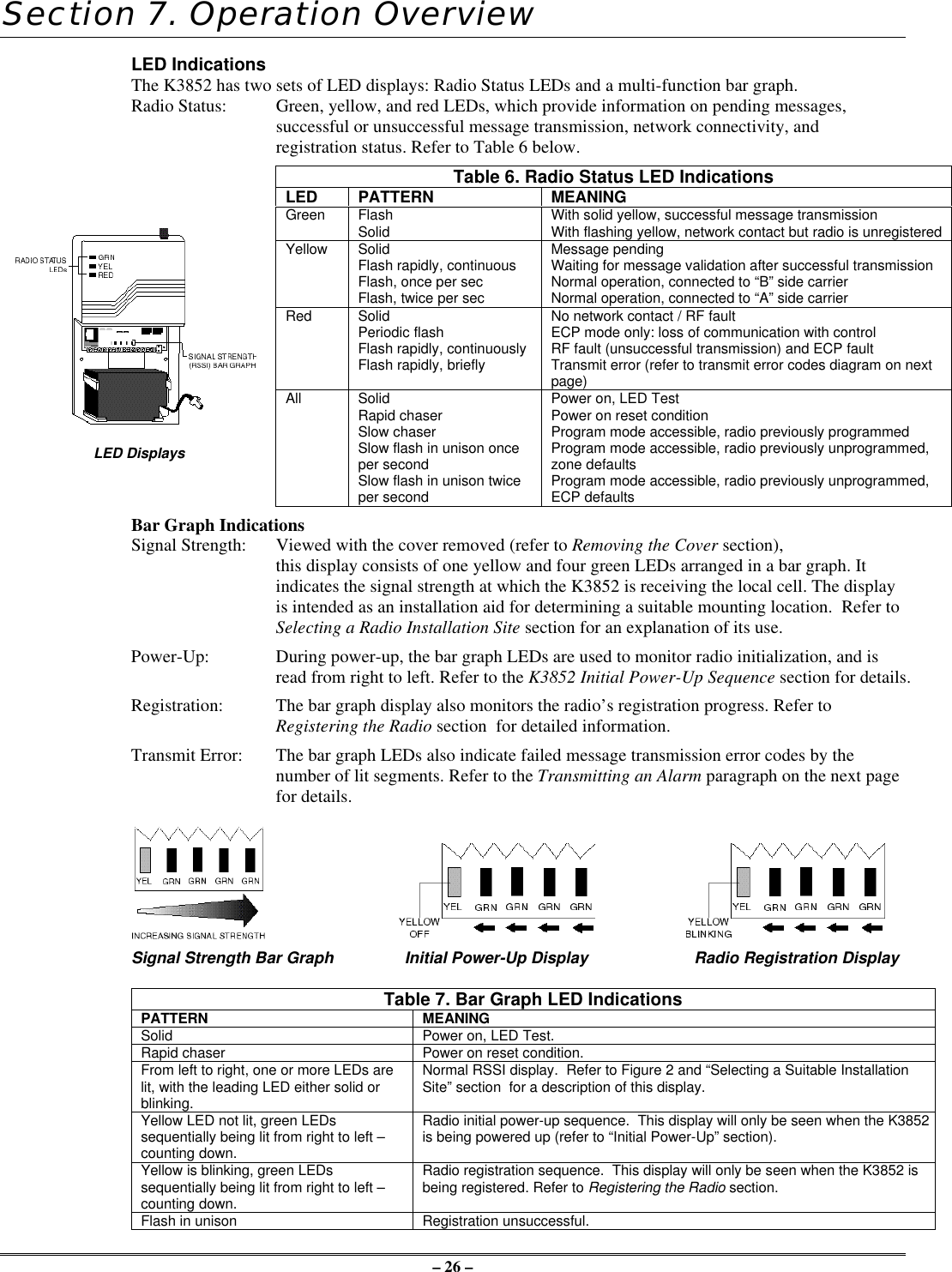
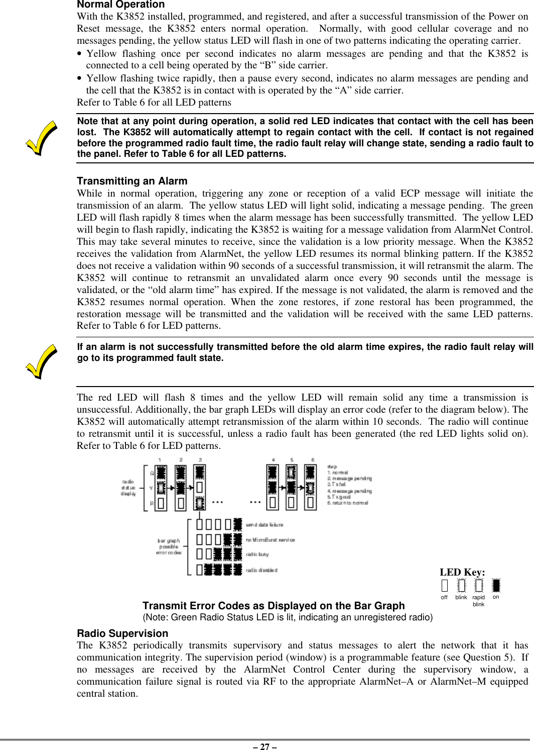
Users Manual
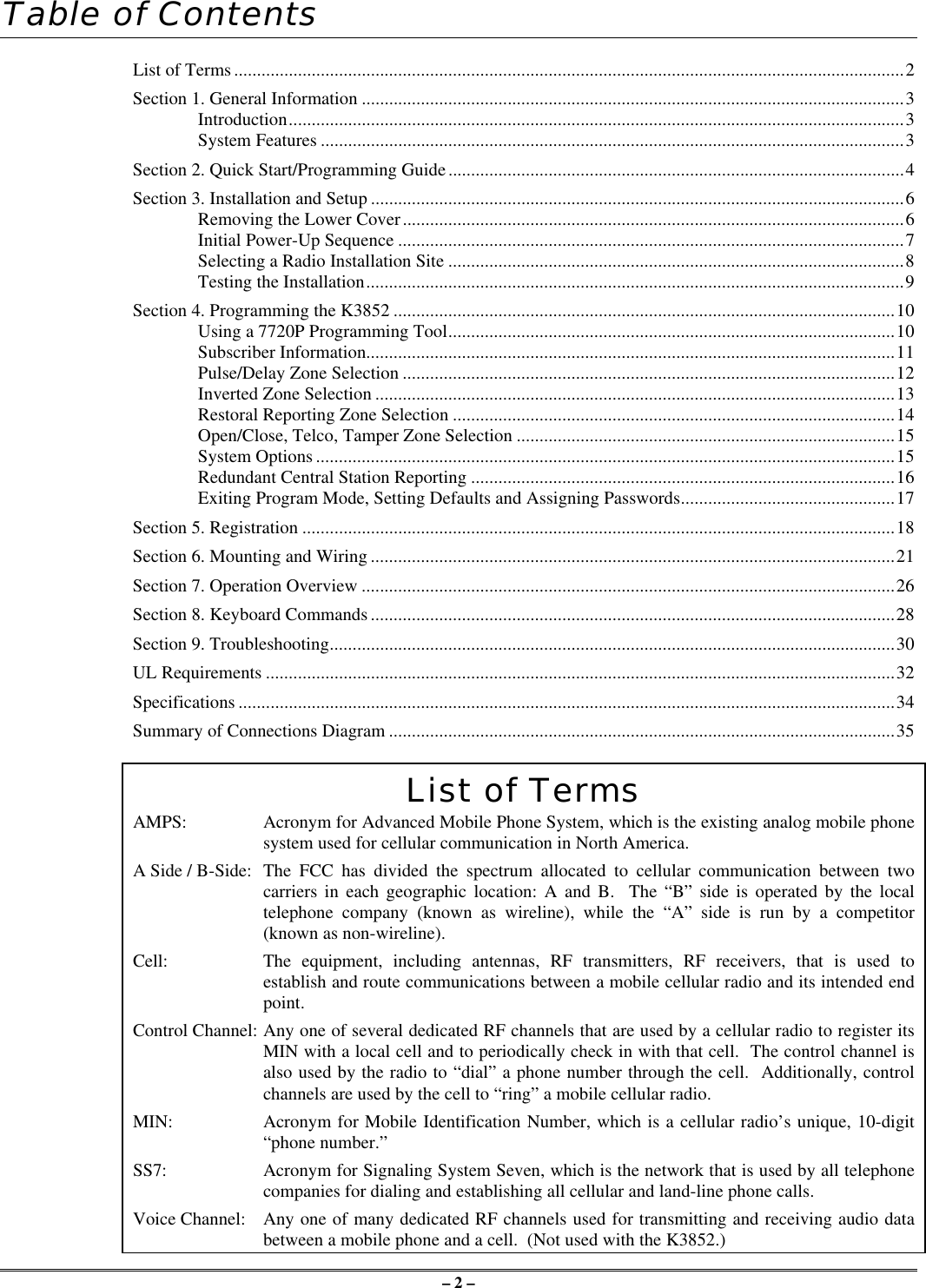

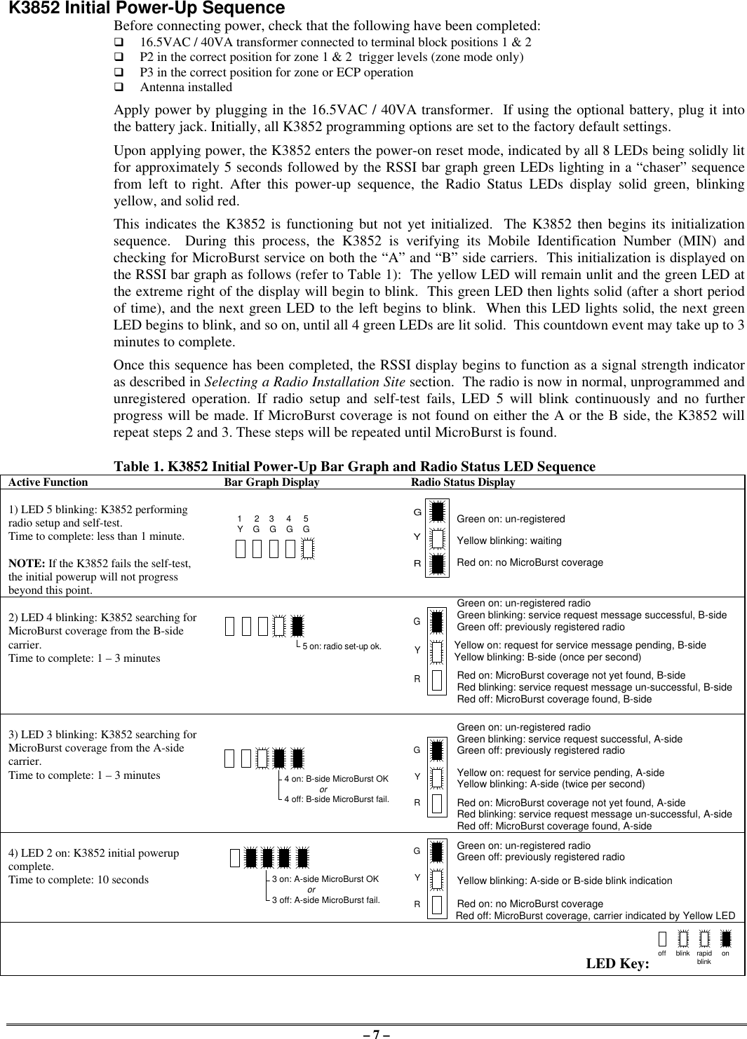
![– 4 –Section 2: Quick Start/Programming Guide1. Unpack and initialize the radio.a. Unpack the K3852 and install the antenna.b. Remove the unit’s lower cover (refer to Removing the Lower Cover section).c. Connect a fully charged battery (Ademco 7720BT) or a 40VA transformer (Ademco 1361 or 1361CN).d. Monitor the initial power-up LED sequence (refer to the Initial Power-Up Sequence section). This cantake several minutes.2. Find coverage and select a site.If this is the first K3852 to be installed in a given area, please verify that there is coverage in that ZIP codeby either checking the coverage selection at the AlarmNet web site www.ademco.com/alarmnet, or bycalling 1-800-222-6525 and asking our technical assistance group.a. Verify MicroBurst coverage using the radio status LEDs as shown atright, or use the “B” command on the 7720P Programming Tool.b. Select an installation site by observing the signal strength (RSSI) bargraph or use the “B” command on the 7720P Programming Tool (referto the Selecting a Radio Installation Site section for detailed procedure).3. Test the site.a. Test the RF link between the K3852 and the local cell with a singleclick test message (refer to the Testing section for details).b. Test communication with the AlarmNet C network by doubleclicking the tamper/test switch and receiving message validation. Ifdesired, you can cancel validation by clicking the tamper switchonce.4. Program the radio.a. Connect the 7720P Programming Tool, reset the radio by cycling the power off then on; press [Enter]during the initial power-up sequence to enter Programming mode.b. Program the K3852 as described in the Programming section. Refer to the programming defaults on thenext page.5. Register the radio.a. Send test registration with the 7720P “T” command to verify account and routing.b. Register the K3852 with AlarmNet by triple clicking the tamper switch and observing the LED displaysas shown below, or by pressing the [↑] key on the 7720P.6. Complete the installation.a. Mount the radio (refer to the Mounting section).b. Wire to the Control (refer to the Wiring section) and test all signals.c. Test the installation (refer to the Testing section)off blink rapidblinkonLED KeyGYRMicroBurst MicroBurstGYR"click"1.5 bars minRSSI RSSIYG G G GGYRGYR"click""click""click"VALIDATIONVALIDATION"click""click""click"REGISTRATIONGYRregistrationprogressYG G G GYG G G GYG G G GYG G G GMSG 1SENT MSG 2SENT MSG 3SENT WAITACK](https://usermanual.wiki/Ademco/K3852.Users-Manual/User-Guide-39324-Page-4.png)
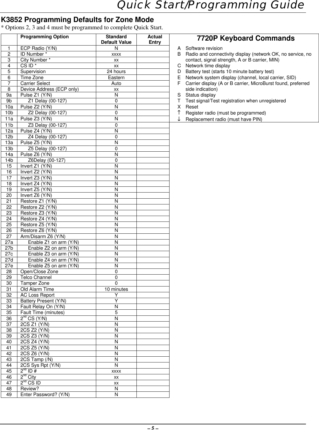
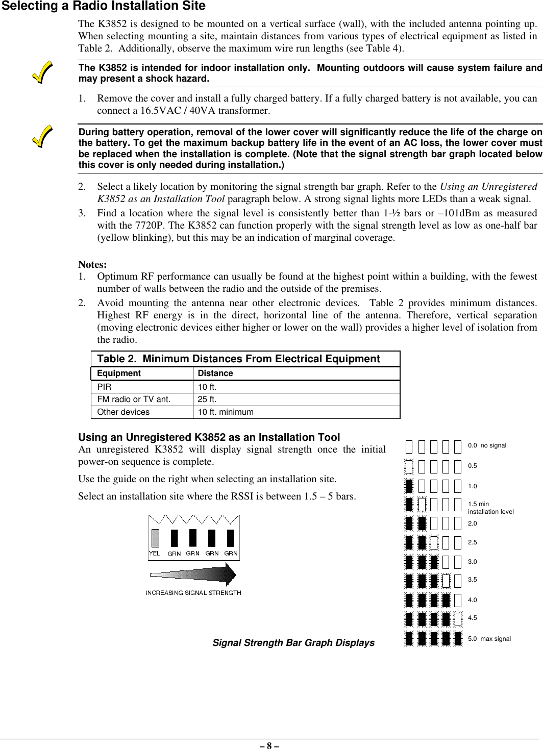
![– 10 – Section 4: Programming the K3852There are 3 methods of programming the K3852: (1) Using a 7720P Programming Tool; (2) using an ECPcapable control panel that supports long range radio programming,; (3) using the ProgrammerlessRegistration Option (PRO).To use the 7720P, connect the 7720P then power-up the radio. Refer to the description below.To use an ECP capable control, connect the control, then power-up the radio. Select ECP operation bypressing the tamper switch once while the radio status LEDs are flashing in unison, which toggles thedefault configuration from zone mode to ECP mode. The unprogrammed K3852 flashes the radio statusLEDs as follows during initial power-up:ECP mode = twice per secondZone mode = once per secondThe default device address of the radio is 3. Refer to the control’s instructions for programming procedures.To use the Programmerless Registration Option, power-up the radio, then contact AlarmNet TechnicalAssistance Center (TAC). Refer to the Programmerless Registration Option Installation and ProgrammingGuide insert.Using a 7720P Programming ToolThe 7720P Programming Tool is powered by the K3852 via the Programming Jack. The K3852 willautomatically sense the presence of the 7720P when it is plugged in.Each key of the 7720P has two possible functions: a normal function and a SHIFT function. To perform anormal key function, simply press the desired key. To perform a SHIFT key function, press the SHIFT key,then press desired function key.Table 3. 7720P Normal & Shift Key (shift LED lit) Functions Key Normal Key Function SHIFT Key FunctionBS/ESC [BS]: Press to delete entry [ESC]: Press to quit program mode;also can reset EEPROM defaults*↓/↑[↓]: Scroll down programming [↑]: Scroll up programmingN/Y [N]: Press for "NO" answer [Y]: Press SHIFT-Y for "YES" answerSHIFT Press before pressing a SHIFT key function. Will light SHIFT LED. LEDgoes out once a key is pressed. Press again for each SHIFT function desired.1/A [1]: For entering the number 1 [A]: For entering letter A2/B [2]: For entering the number 2 [B]: For entering letter B3/C [3]: For entering the number 3 [C]: For entering letter C4/D [4]: For entering the number 4 [D]: For entering letter D5/E [5]: For entering the number 5 [E]: For entering letter E6/F [6]: For entering the number 6 [F]: For entering letter F7/S [7]: For entering the number 7 [S]: For entering letter S8/T [8]: For entering the number 8 [T]: For entering letter T9/X [9]: For entering the number 9 [X]: For entering letter X*/SPACE [*]: For scrolling option list [SPACE]: For scrolling option list0[0]: For entering the number 0 No SHIFT function #/ENTER [#/ENTER]: Press to accept entries No SHIFT function* Active only when the "REVIEW?" prompt is displayed.After connecting the 7720P cable, power up the K3852 . The following will be displayed:K3852 x.xx(c) Pittway 1999x.xx = current software revision level NOTE: This document applies to software Rev. 1.20 or higherAt this prompt during initial power-up, you may proceed with programming the K3852. Programming isaccomplished by answering displayed questions. Most questions require only a [Y]es or [N]o response,while others require a numerical response (ID numbers, etc.). Press ENTER to accept each response andproceed to the next question. A "?" indicates an invalid entry. The current value is displayed on the secondline in parentheses ( ). To accept the current entry, simply press the ENTER key. If the current value is aninvalid entry, pressing the enter key will cause the display to repeat the unanswered question; the nextquestion will not be displayed until a valid answer is entered. Use the UP/DOWN arrow keys to scrollthrough the programming questions without changing any values. The ESC key will bring the list ofquestions to the end.](https://usermanual.wiki/Ademco/K3852.Users-Manual/User-Guide-39324-Page-10.png)
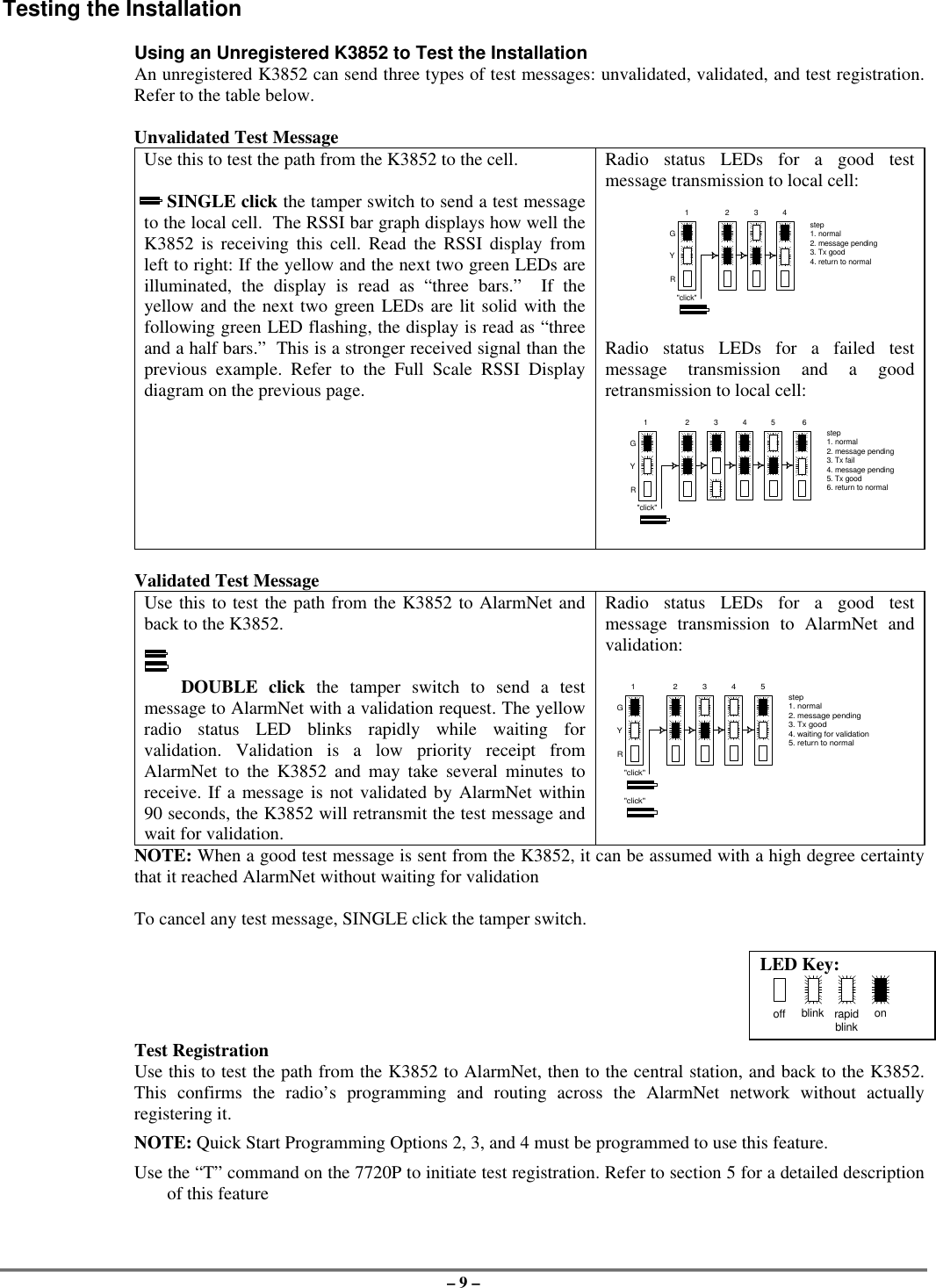
![– 11 –Enter programming mode by pressing [ENTER] during the initial power-up period after the chasersequence (while radio status LEDs are flashing consecutively or in unison).The K3852 reads its EEROM to determine its preprogrammed parameters. A CRC of the EEROMlocations is also read. If the computed CRC does not match the one read from EEROM, or if theprogramming parameters are invalid, the 7720P LCD displays "NO PROG" and the radio status LEDs flashin unison (after the initial chaser sequence). Otherwise, the LEDs flash consecutively.Password ProtectionIf you are NOT programming the radio through an ECP capable control panel (e.g., VISTA-128FB), theprogramming menu can be password protectedOnce a password is assigned, the following prompt appears upon entering programming mode:ENTER PASSWORD:See “Exiting Program Mode” paragraph later in this section for assigning and changing passwords.Subscriber Information (Questions 1-7)Question 1*. ECP Radio(Y/N) Press “Y” to enable ECP communication for alarm input (check thatjumper P3 is to right). Press “N” to enable voltage triggers for alarminput.* This question will NOT appear if you are programming via the controlpanel, since ECP mode is automatically required; Question 2 will be thefirst programming option displayed on the keypad.Question 2. ID # Enter the 4-digit customer account number, 0001-9999.Question 3. City Enter the 2-digit primary city code, 01-99 (decimal).Question 4. CS ID Enter the primary central station's system ID number, 01-FE.Question 5. Supervision(24Hr.)This selection sets the supervision timing for the K3852 for either 24hour or weekly. The default supervision timing is 24 hours. The K3852sends a supervision message once during the supervision period.AlarmNet transmits a communications failure alarm to the central stationif the supervision message is not heard within the period.Use the Space key to select weekly or 24 hour supervision.Must be set to 24 hr for UL installations.Question 6. Time Zone(Eastern)Use the [*] key to select the time zone in which the K3852 is beinginstalled: Eastern, Central, Mountain, Pacific, or Atlantic.Question 7. Carrier Select(Auto)Use the [*] key to choose the method by which the K3852 will select itscellular carrier: “A” or “B” side.Auto: K3852 selects the carrier to which it will connect. In this mode,the K3852 will automatically change its carrier side if coveragebecomes degraded.NOTE: If the K3852 had been operating and competed itsinitialization sequence with this option set to “auto,” one of thefollowing prompts will appear:Auto B then A: shows that the B-side carrier was initially selected.Auto A then B: shows that the A-side carrier was initially selected.These prompts are displays only, not programming choices, andthe prompt will disappear if the [*] key is pressed.A then B: K3852 prefers connecting to the “A” side carrier rather than the“B” side carrier. If coverage is lost on the A side, the radio willswitch to the “B” side carrier.B then A: K3852 prefers connecting to the “B” side carrier rather than the“A” side carrier. If coverage is lost on the B side, the radio willswitch to the “A” side carrier.A Only: K3852 searches for coverage on the “A” side only. Fixed carrieroperation.B Only: K3852 searches for coverage on the “B” side only. Fixed carrieroperation.](https://usermanual.wiki/Ademco/K3852.Users-Manual/User-Guide-39324-Page-11.png)

![– 17 –Exiting Program Mode, Setting Defaults & Assigning PasswordsWhen the last question is answered, the system validates all entries. If no errors are found, the following isdisplayed:REVIEW?To review the programming options (to ensure that the correct responses have been made), press “Y.” Theprogramming questions will be displayed again, starting with Question 1. Use the UP/DOWN arrow keysto scroll through the program fields without changing any of the values. If a value requires change, simplytype in the correct value. When the last field is displayed, the “REVIEW?” question again appears.Setting Factory Defaults: You can reset the programming options globally to their factory default valuesby pressing ESC at the “REVIEW?” prompt. A confirmation prompt will appear. Press “Y” to reset, orpress “N” to cancel this function. If you press “Y,” all programmed values will be reset to their originalfactory settings.To exit program mode and assign passwords, press “N” in response to the “REVIEW?” question. If youare NOT programming the radio through a panel and no password has been assigned, the followingappears:ENTER PASSWORD?[Y/N]Passwords can be used to split the programming questions intotwo menus. See the “Password Protection” paragraph earlier inthis section. If a password is desired, press “Y”. The followingprompts appear. Press “N” if no passwords are desired.If a password has already been assigned for the current programming menu, the “ENTER PASSWORD?”prompt is replaced by the following:CHG PASSWORD?[Y/N]Press “Y” or “N,” depending on whether you want to change thepassword for the current programming menu. If [Y]es, you willbe prompted to enter the new password twice (as confirmation).To clear an existing password, answer "Y" to the "CHGPASSWORD" prompt, but press only the ENTER key whenprompted for the new password and its confirmation.ENTER PASSWORD: Enter the 4-digit password.VERIFY PASSWORD: Reenter the 4-digit password as confirmation.When the password question(s) have been answered, the system exits program mode and returns to normalmode. You can then disconnect the programming tool, or use it to trigger test messages. Refer to Testingthe System section.](https://usermanual.wiki/Ademco/K3852.Users-Manual/User-Guide-39324-Page-17.png)
![– 18 –Section 5: RegistrationTest RegistrationPrior to registering the radio, a test registration can be sent. The test registration is used to confirm theprogramming of the radio and the routing across the AlarmNet C network without actually registering theradio. This feature requires a 7720P.To initiate a test registration, first complete Quick Start programming. Options 2, 3, and 4 must beprogrammed. After this, press shift-“T” on a connected 7720P. Test registration progress messages will bedisplayed on the 7720P as described in the Interactive Registration paragraph below. When a testregistration has been completed, the radio will be reported to the central station as 5555 5555 9. Thisindicates that the radio is programmed and routed correctly, but is not registered. If test registration fails, amessage on the 7720P will indicate the failure.Registering the RadioOnce you have initialized and programmed the K3852, you must register it with AlarmNet Control. Anunregistered K3852 is indicated on the radio status LEDs as: solid green, blinking yellow, and unlit red.The registration process consists of transmitting 3 messages in succession and receiving a registrationvalidation from AlarmNet Control. It can take several minutes to complete.Initiate the registration sequence by either clicking the tamper switch 3 times or by pressing shift and the uparrow [↑] on the 7720P. If you are using a 7720P, skip to the Interactive Registration section.You can monitor the registration process on the RSSI display as follows: yellow LED will be blinking andthe green LED at the extreme right of the display will blink. When this green LED lights solid, the nextgreen LED to the left begins to blink. When this LED lights solid, the next green LED begins to blink, andso on, until all 4 green LEDs are lit solid.Once you have successfully completed the registration, the radio will enter normal operating mode; thegreen radio status LED extinguishes, the yellow radio status LED continues normal blinking, and the RSSIdisplay indicates received signal strength.If registration is not validated within 90 seconds, the K3852 will time out and all 5 RSSI LEDs will blink inunison for 30 seconds. If repeated registration attempts time out, select a new installation site.If the K3852 has been programmed with an invalid ID, city, or central station number, the registration willbe rejected. The right green LED will blink alternately with the remaining 4 RSSI LEDs.off blink rapidblinkonLED Key"click""click""click"REGISTRATIONGYRregistrationprogressYG G G GYG G G GYG G G GYG G G GMSG 1SENT MSG 2SENT MSG 3SENT WAITACK](https://usermanual.wiki/Ademco/K3852.Users-Manual/User-Guide-39324-Page-18.png)
![– 19 –Interactive RegistrationThe interactive registration feature allows the installer to register the K3852 through a series of keyboardcommands on the 7720P installation tool. This method of registration lets the installer monitor theregistration process.RegistrationMSG1 SentRegistrationMSG2 SentRegistrationMSG3 SentRegistrationWaiting for ACKOnce the installation is complete the installer should select the[↑] command on the 7720P.Three messages are sent, then the unit waits foracknowledgement.RegistrationSuccessful!If this is a new installation, and the City, CS, and Cust# havebeen correctly entered, the K3852 will be registered and thismessage will be displayed. At this point the K3852 is in fullservice and available for alarm reporting to the central station.Possible ErrorsMIN Exists This prompt may appear only if this is a test registration andindicates that a different account number is already associatedwith this MIN in the AlarmNet database.RegistrationTimed Out!If no response to the registration request is received fromAlarmNet, this message will be displayed.Reg RejectBad ID! PSIf the City, CS, and Cust# were not correctly entered, thismessage will be displayed.If this message is displayed with a “P” primary ID, and or an “S”secondary ID, it indicates that the ID information was eitherentered in error, or the central station failed to pre-authorizeprogrammed ID numbers with AlarmNet customer service.Account ExistsSub Y/NThis prompt is displayed if this is a repair/replacement, or an errorwas made in programming the K3852 for an existing account.If this is a test registration, the opportunity to substitute the radiowill not be offered.Replacement RadiosDo You Have APIN # Y/NAt this point the installer should havecalled in for a 4-digit alpha numeric PIN# that must be obtained by having anauthorized person call the AlarmNetTechnical Assistance Center (TAC).Answering “Y“ will continue theregistration process. Answering “N” willabort the process. If “Y” was selectedthen the next prompt will be displayed.](https://usermanual.wiki/Ademco/K3852.Users-Manual/User-Guide-39324-Page-19.png)
![– 20 –Alarm Will BeSent, OK Y/NIf the installer proceeds beyond thispoint by answering “Y,” a correct PINnumber must be supplied to completethe registration. Any attempt atregistration at this point, whethersuccessful or unsuccessful, will result ina radio substitution alarm being sent tothe CS. Answering “Y” allows theinstaller to continue registration.Answering “N” will abort the registration.If “Y” was chosen, see the next section onReplacement Radios for the remainder ofthe process.If the installation is a known repair/replacement, you can skip the previous section by selecting the[↓] command to initiate the replacement registration process, beginning with the PIN entry asfollows.Enter PIN# The installer must enter a 4 digit alphanumeric PIN # that must be obtained byhaving an authorized person call theAlarmNet TAC (Technical AssistanceCenter). The PIN should be entered,followed by the enter key.RegistrationMSG1 SentRegistrationMSG2 SentRegistrationMSG3 SentRegistrationWaiting for ACKThree messages are sent, then the unitwaits for acknowledgement.RegistrationSuccessful!If the PIN is valid, the new K3852 willregister and the old unit will beunregistered. A radio substitution alarm willbe sent to the central station by AlarmNet.RegistrationCanceled!If at any point in the substitution processthe installer chooses not to register theK3852, this is the displayed message.SubstitutionRejected!If an invalid PIN was entered this is thedisplay message, and the registrationprocess will be aborted and will need tobe started from the beginning. Note thateach attempt will cause a radiosubstitution alarm to be sent to the centralstation.](https://usermanual.wiki/Ademco/K3852.Users-Manual/User-Guide-39324-Page-20.png)
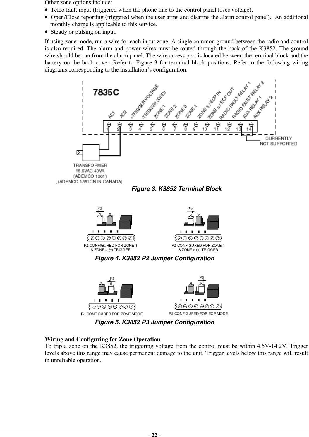
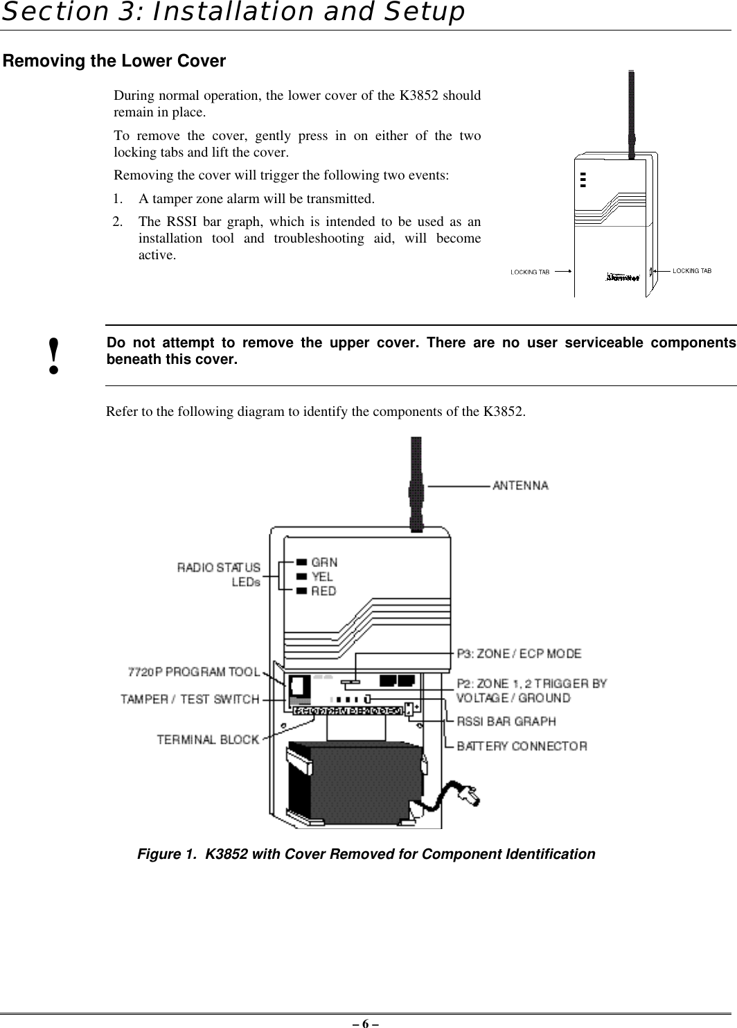
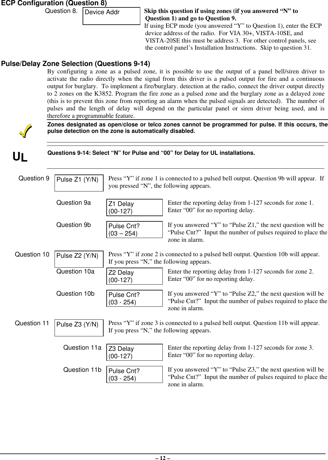
![– 25 –Wiring for Radio FaultsYou may program the radio fault output relay (refer to Programming the K3852 section) for either:FAIL-SAFE mode (UL requirement)•Answer “Y” to “FLT REL ON (Y/N)”•Relay always energized [N.C.]•Relay will change state (and trigger a dialer, ifconnected) in the event of power loss.•Fail-safe mode increases the standby current by about10mA, which results in lower battery backup time(about 15%) in the event of power loss.LOW CURRENT mode•Answer “N” to “FLT REL ON (Y/N)”•Relay normally de-energized [N.O.]•Does not increase standby current•NOT approved for UL installations.Run two wires from the K3852’s radio fault terminals 11 and 12 to a zone on the control panel. Refer to theFigures below for wiring the radio fault relay.Figure 11. Wiring the K3852 to trip a control panel zone Figure 12. Wiring the K3852 to trip aduring a radio fault (required for UL installations) control panel zone for normally open fault(not UL approved)AC Power ConnectionsPrimary power for the K3852 is provided by a wall-mounted 16.5VAC / 40VA transformer ADEMCO PN:1361 (1361CN in Canada). Use of a transformer with a lower power rating will result in unreliable systemoperation.Connect the AC power wires from the 16.5V 40VA wall transformer to terminals 1 and 2 on the K3852. Donot plug the transformer into the AC power source until all wiring connections have been made and you areready to power up the K3852. Refer to the K3852 Initial Power-Up Sequence section.Backup Battery ConnectionThe optional battery backup (ADEMCO 7720BT) can provide over 4 hours of system life in the event of anAC power failure. When AC power is lost, the K3852 enters a low-power state and the programmable ACloss message can alert the AlarmNet Control Center (AC loss messages are reported within 10-40 minutesof actual AC loss). Any alarms that are tripped during this low-power state will wake the system up totransmit the appropriate message. After a successful transmission, the K3852 will reenter its low-powerstate. When the battery reaches 10.5V, a low-battery message is transmitted, which alerts the AlarmNetControl Center that this may be the radio’s last message. When the battery reaches 8.5V, radiotransmissions are no longer possible and the system shuts down. If AC power is restored before the systemshuts down, an AC Restore message will be sent and the battery will be recharged using the K3852’s built-in battery charger. If AC power is restored after the system has shut down, a power-on reset conditionexists, and the radio will initialize itself as described earlier and the battery will be recharged.The K3852 performs a battery test under load on a daily basis. During this test, if the battery drops below10.5V, a low-battery message will be generated to indicate that the battery should be replaced.To install the battery, snap it into the battery holder with the connector wire towards the lower right. Do notplug the battery in until all wiring connections have been made and you are ready to power up the K3852.Refer to K3852 Initial Power-Up Sequence section. When you are ready to power up the radio, plug thebattery connector into the battery jack located on the right-hand side of the K3852 terminal strip.Lower cover must be in place for the K3852 to enter its lower power state during battery operation.](https://usermanual.wiki/Ademco/K3852.Users-Manual/User-Guide-39324-Page-25.png)