Ademco K3852 Cellular Control Channel Transceiver User Manual K3852InstallationAnd SetupGuide

Honeywell International Inc. Cellular Control Channel Transceiver K3852InstallationAnd SetupGuide

Users Manual

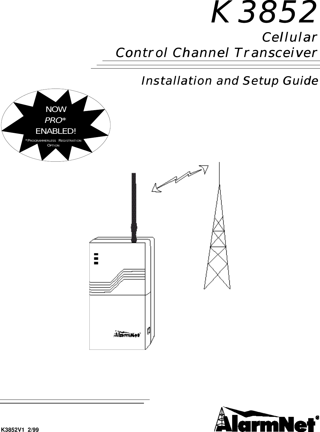
K3852K3852CellularCellularControl Channel TransceiverControl Channel TransceiverInstallation and Setup GuideInstallation and Setup GuideNOWPRO*ENABLED!*PROGRAMMERLESS  REGISTRATIONOPTIONK3852V1  2/99
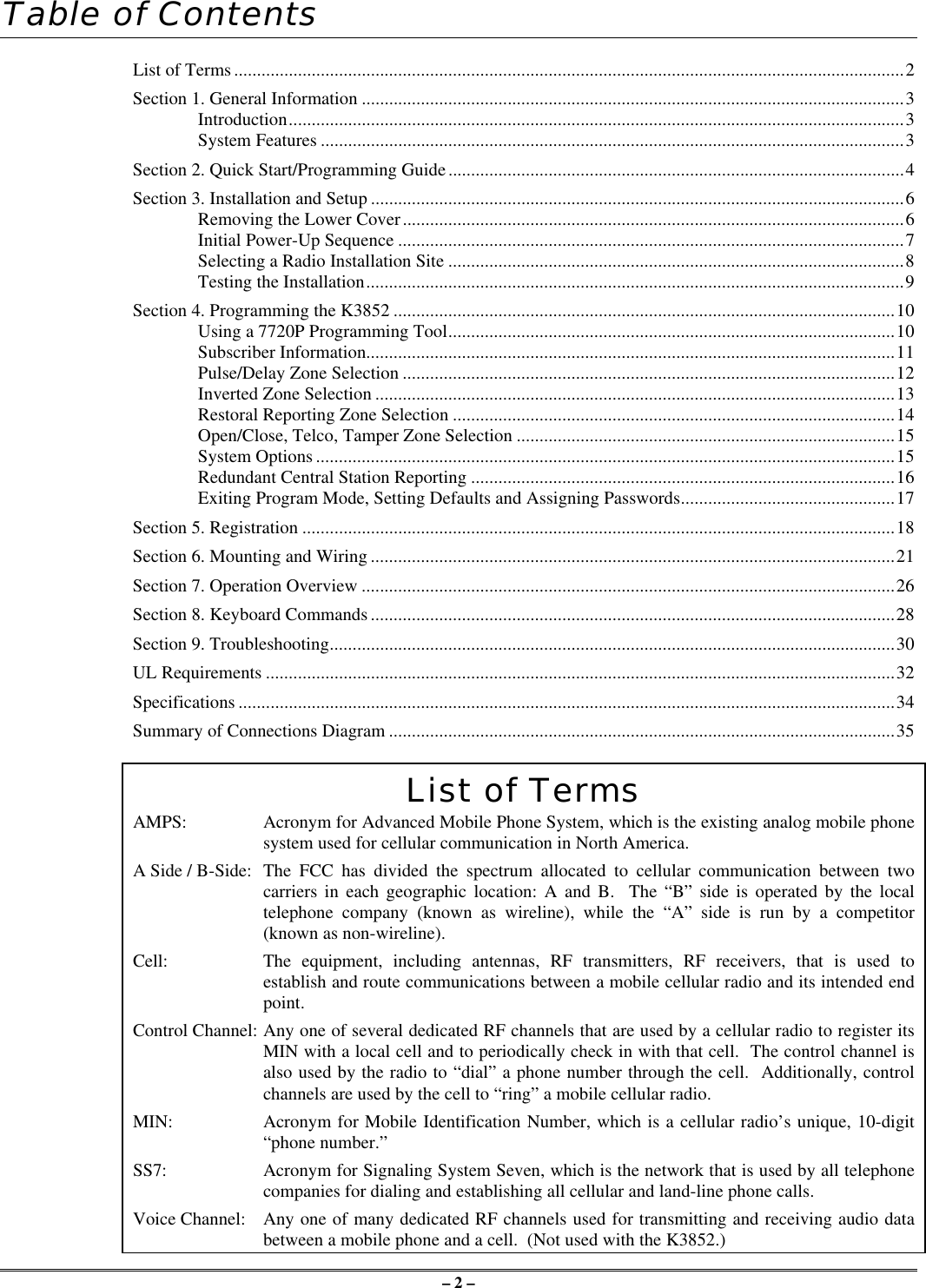
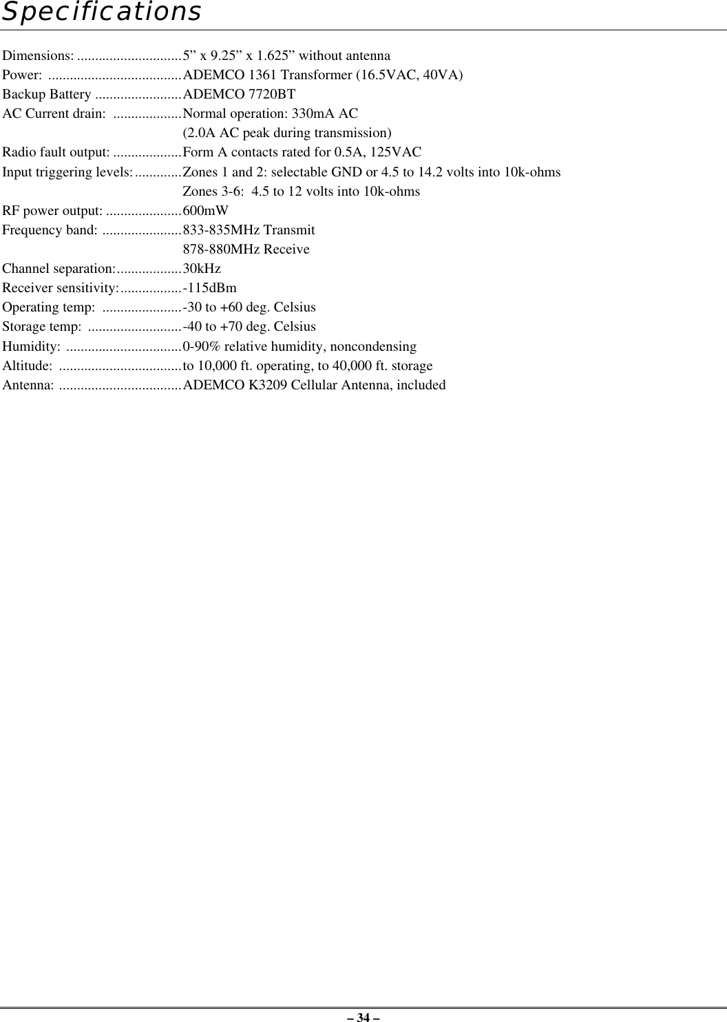
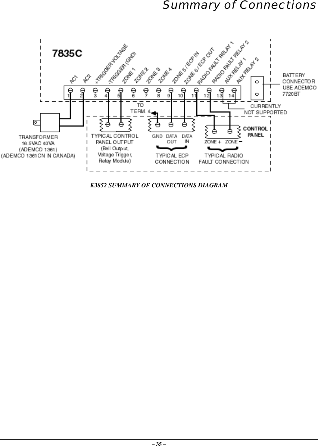
– 2 –Table of ContentsList of Terms...................................................................................................................................................2Section 1. General Information .......................................................................................................................3Introduction.......................................................................................................................................3System Features ................................................................................................................................3Section 2. Quick Start/Programming Guide....................................................................................................4Section 3. Installation and Setup .....................................................................................................................6Removing the Lower Cover..............................................................................................................6Initial Power-Up Sequence ...............................................................................................................7Selecting a Radio Installation Site ....................................................................................................8Testing the Installation......................................................................................................................9Section 4. Programming the K3852 ..............................................................................................................10Using a 7720P Programming Tool..................................................................................................10Subscriber Information....................................................................................................................11Pulse/Delay Zone Selection ............................................................................................................12Inverted Zone Selection ..................................................................................................................13Restoral Reporting Zone Selection .................................................................................................14Open/Close, Telco, Tamper Zone Selection ...................................................................................15System Options ...............................................................................................................................15Redundant Central Station Reporting .............................................................................................16Exiting Program Mode, Setting Defaults and Assigning Passwords...............................................17Section 5. Registration ..................................................................................................................................18Section 6. Mounting and Wiring ...................................................................................................................21Section 7. Operation Overview .....................................................................................................................26Section 8. Keyboard Commands ...................................................................................................................28Section 9. Troubleshooting............................................................................................................................30UL Requirements ..........................................................................................................................................32Specifications ................................................................................................................................................34Summary of Connections Diagram ...............................................................................................................35List of TermsAMPS: Acronym for Advanced Mobile Phone System, which is the existing analog mobile phonesystem used for cellular communication in North America.A Side / B-Side: The FCC has divided the spectrum allocated to cellular communication between twocarriers in each geographic location: A and B.  The “B” side is operated by the localtelephone company (known as wireline), while the “A” side is run by a competitor(known as non-wireline).Cell:  The equipment, including antennas, RF transmitters, RF receivers, that is used toestablish and route communications between a mobile cellular radio and its intended endpoint.Control Channel: Any one of several dedicated RF channels that are used by a cellular radio to register itsMIN with a local cell and to periodically check in with that cell.  The control channel isalso used by the radio to “dial” a phone number through the cell.  Additionally, controlchannels are used by the cell to “ring” a mobile cellular radio.MIN:  Acronym for Mobile Identification Number, which is a cellular radio’s unique, 10-digit“phone number.”SS7:   Acronym for Signaling System Seven, which is the network that is used by all telephonecompanies for dialing and establishing all cellular and land-line phone calls.Voice Channel: Any one of many dedicated RF channels used for transmitting and receiving audio databetween a mobile phone and a cell.  (Not used with the K3852.)
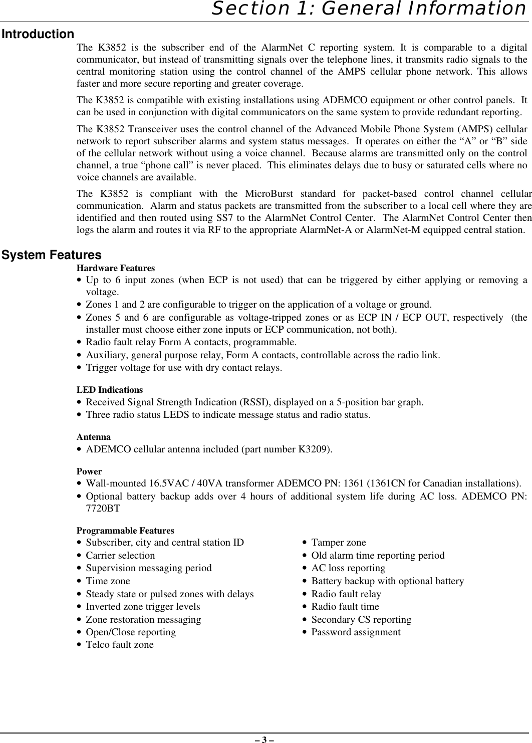
– 3 –Section 1: General InformationIntroduction The K3852 is the subscriber end of the AlarmNet C reporting system. It is comparable to a digitalcommunicator, but instead of transmitting signals over the telephone lines, it transmits radio signals to thecentral monitoring station using the control channel of the AMPS cellular phone network. This allowsfaster and more secure reporting and greater coverage.The K3852 is compatible with existing installations using ADEMCO equipment or other control panels.  Itcan be used in conjunction with digital communicators on the same system to provide redundant reporting.The K3852 Transceiver uses the control channel of the Advanced Mobile Phone System (AMPS) cellularnetwork to report subscriber alarms and system status messages.  It operates on either the “A” or “B” sideof the cellular network without using a voice channel.  Because alarms are transmitted only on the controlchannel, a true “phone call” is never placed.  This eliminates delays due to busy or saturated cells where novoice channels are available.The K3852 is compliant with the MicroBurst standard for packet-based control channel cellularcommunication.  Alarm and status packets are transmitted from the subscriber to a local cell where they areidentified and then routed using SS7 to the AlarmNet Control Center.  The AlarmNet Control Center thenlogs the alarm and routes it via RF to the appropriate AlarmNet-A or AlarmNet-M equipped central station.System FeaturesHardware Features• Up to 6 input zones (when ECP is not used) that can be triggered by either applying or removing avoltage.• Zones 1 and 2 are configurable to trigger on the application of a voltage or ground.• Zones 5 and 6 are configurable as voltage-tripped zones or as ECP IN / ECP OUT, respectively  (theinstaller must choose either zone inputs or ECP communication, not both).• Radio fault relay Form A contacts, programmable.• Auxiliary, general purpose relay, Form A contacts, controllable across the radio link.• Trigger voltage for use with dry contact relays.LED Indications• Received Signal Strength Indication (RSSI), displayed on a 5-position bar graph.• Three radio status LEDS to indicate message status and radio status.Antenna• ADEMCO cellular antenna included (part number K3209).Power• Wall-mounted 16.5VAC / 40VA transformer ADEMCO PN: 1361 (1361CN for Canadian installations).• Optional battery backup adds over 4 hours of additional system life during AC loss. ADEMCO PN:7720BTProgrammable Features• Subscriber, city and central station ID •Tamper zone• Carrier selection •Old alarm time reporting period• Supervision messaging period •AC loss reporting• Time zone •Battery backup with optional battery• Steady state or pulsed zones with delays •Radio fault relay• Inverted zone trigger levels •Radio fault time• Zone restoration messaging •Secondary CS reporting• Open/Close reporting •Password assignment• Telco fault zone
– 4 –Section 2: Quick Start/Programming Guide1. Unpack and initialize the radio.a. Unpack the K3852 and install the antenna.b. Remove the unit’s lower cover (refer to Removing the Lower Cover section).c. Connect a fully charged battery (Ademco 7720BT) or a 40VA transformer (Ademco 1361 or 1361CN).d. Monitor the initial power-up LED sequence (refer to the Initial Power-Up Sequence section). This cantake several minutes.2. Find coverage and select a site.If this is the first K3852 to be installed in a given area, please verify that there is coverage in that ZIP codeby either checking the coverage selection at the AlarmNet web site www.ademco.com/alarmnet, or bycalling 1-800-222-6525 and asking our technical assistance group.a. Verify MicroBurst coverage using the radio status LEDs as shown atright, or use the “B” command on the 7720P Programming Tool.b. Select an installation site by observing the signal strength (RSSI) bargraph or use the “B” command on the 7720P Programming Tool (referto the Selecting a Radio Installation Site section for detailed procedure).3. Test the site.a. Test the RF link between the K3852 and the local cell with a singleclick test message (refer to the Testing section for details).b. Test communication with the AlarmNet C network by doubleclicking the tamper/test switch and receiving message validation. Ifdesired, you can cancel validation by clicking the tamper switchonce.4. Program the radio.a. Connect the 7720P Programming Tool, reset the radio by cycling the power off then on; press [Enter]during the initial power-up sequence to enter Programming mode.b. Program the K3852 as described in the Programming section. Refer to the programming defaults on thenext page.5. Register the radio.a. Send test registration with the 7720P “T” command to verify account and routing.b. Register the K3852 with AlarmNet by triple clicking the tamper switch and observing the LED displaysas shown below, or by pressing the [↑] key on the 7720P.6. Complete the installation.a. Mount the radio (refer to the Mounting section).b. Wire to the Control (refer to the Wiring section) and test all signals.c. Test the installation (refer to the Testing section)off blink rapidblinkonLED KeyGYRMicroBurst MicroBurstGYR"click"1.5 bars minRSSI RSSIYG G G GGYRGYR"click""click""click"VALIDATIONVALIDATION"click""click""click"REGISTRATIONGYRregistrationprogressYG G G GYG G G GYG G G GYG G G GMSG 1SENT MSG 2SENT MSG 3SENT WAITACK
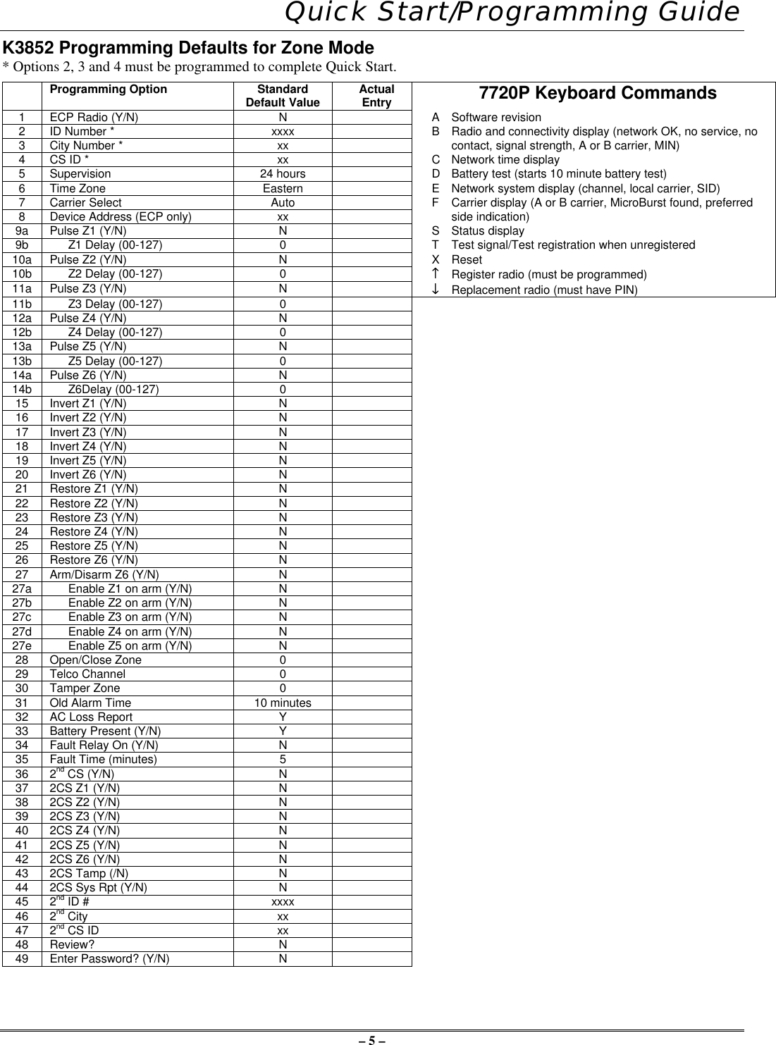
– 5 – Quick Start/Programming GuideK3852 Programming Defaults for Zone Mode* Options 2, 3 and 4 must be programmed to complete Quick Start.Programming Option StandardDefault Value ActualEntry 7720P Keyboard Commands1ECP Radio (Y/N) NASoftware revision2ID Number * xxxx BRadio and connectivity display (network OK, no service, no3City Number * xx contact, signal strength, A or B carrier, MIN)4CS ID * xx CNetwork time display5Supervision 24 hours DBattery test (starts 10 minute battery test)6Time Zone Eastern ENetwork system display (channel, local carrier, SID)7Carrier Select Auto FCarrier display (A or B carrier, MicroBurst found, preferred8Device Address (ECP only) xx side indication)9a Pulse Z1 (Y/N) NSStatus display9b Z1 Delay (00-127) 0TTest signal/Test registration when unregistered10a Pulse Z2 (Y/N) NXReset10b Z2 Delay (00-127) 0↑↑ Register radio (must be programmed)11a Pulse Z3 (Y/N) N↓↓ Replacement radio (must have PIN)11b Z3 Delay (00-127) 012a Pulse Z4 (Y/N) N12b Z4 Delay (00-127) 013a Pulse Z5 (Y/N) N13b Z5 Delay (00-127) 014a Pulse Z6 (Y/N) N14b Z6Delay (00-127) 015 Invert Z1 (Y/N) N16 Invert Z2 (Y/N) N17 Invert Z3 (Y/N) N18 Invert Z4 (Y/N) N19 Invert Z5 (Y/N) N20 Invert Z6 (Y/N) N21 Restore Z1 (Y/N) N22 Restore Z2 (Y/N) N23 Restore Z3 (Y/N) N24 Restore Z4 (Y/N) N25 Restore Z5 (Y/N) N26 Restore Z6 (Y/N) N27 Arm/Disarm Z6 (Y/N) N27a Enable Z1 on arm (Y/N) N27b Enable Z2 on arm (Y/N) N27c Enable Z3 on arm (Y/N) N27d Enable Z4 on arm (Y/N) N27e Enable Z5 on arm (Y/N) N28 Open/Close Zone 029 Telco Channel 030 Tamper Zone 031 Old Alarm Time 10 minutes32 AC Loss Report Y33 Battery Present (Y/N) Y34 Fault Relay On (Y/N) N35 Fault Time (minutes) 536 2nd CS (Y/N) N37 2CS Z1 (Y/N) N38 2CS Z2 (Y/N) N39 2CS Z3 (Y/N) N40 2CS Z4 (Y/N) N41 2CS Z5 (Y/N) N42 2CS Z6 (Y/N) N43 2CS Tamp (/N) N44 2CS Sys Rpt (Y/N) N45 2nd ID # xxxx46 2nd City xx47 2nd CS ID xx48 Review? N49 Enter Password? (Y/N) N
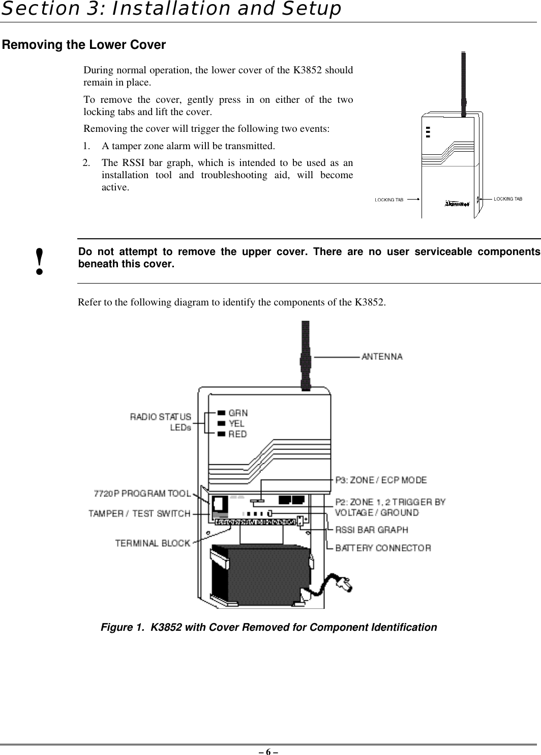
– 6 –Section 3: Installation and SetupRemoving the Lower CoverDuring normal operation, the lower cover of the K3852 shouldremain in place.To remove the cover, gently press in on either of the twolocking tabs and lift the cover.Removing the cover will trigger the following two events:1. A tamper zone alarm will be transmitted.2. The RSSI bar graph, which is intended to be used as aninstallation tool and troubleshooting aid, will becomeactive.!Do not attempt to remove the upper cover. There are no user serviceable componentsbeneath this cover.Refer to the following diagram to identify the components of the K3852.Figure 1.  K3852 with Cover Removed for Component Identification
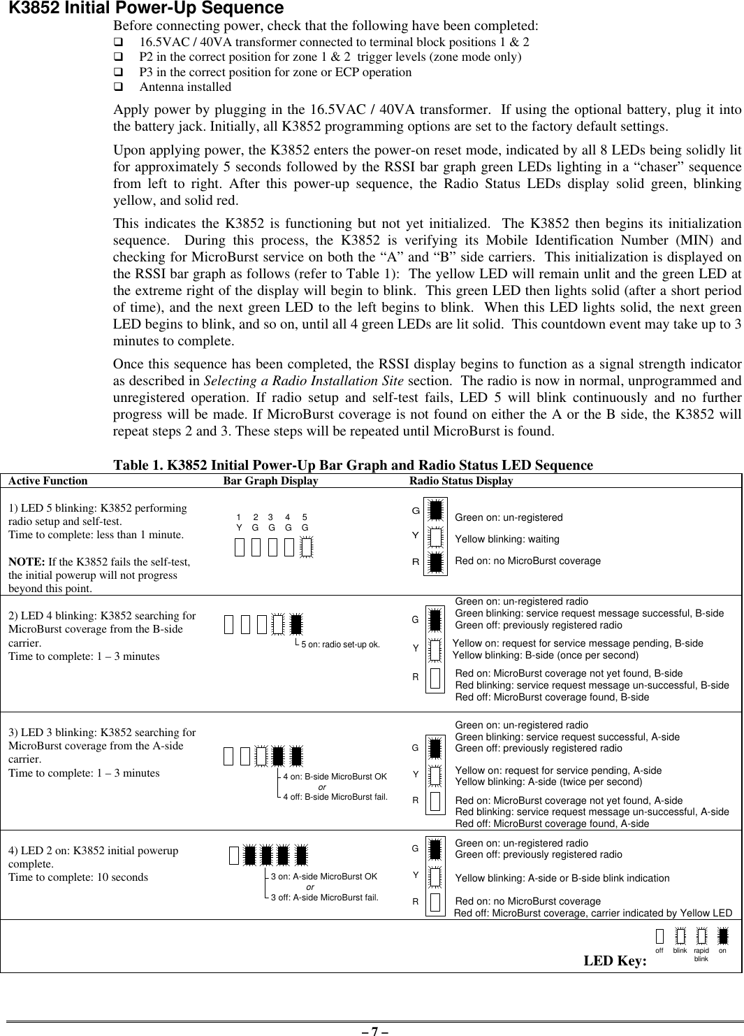
– 7 –K3852 Initial Power-Up SequenceBefore connecting power, check that the following have been completed:q 16.5VAC / 40VA transformer connected to terminal block positions 1 & 2q P2 in the correct position for zone 1 & 2  trigger levels (zone mode only)q P3 in the correct position for zone or ECP operationq Antenna installedApply power by plugging in the 16.5VAC / 40VA transformer.  If using the optional battery, plug it intothe battery jack. Initially, all K3852 programming options are set to the factory default settings.Upon applying power, the K3852 enters the power-on reset mode, indicated by all 8 LEDs being solidly litfor approximately 5 seconds followed by the RSSI bar graph green LEDs lighting in a “chaser” sequencefrom left to right. After this power-up sequence, the Radio Status LEDs display solid green, blinkingyellow, and solid red.This indicates the K3852 is functioning but not yet initialized.  The K3852 then begins its initializationsequence.  During this process, the K3852 is verifying its Mobile Identification Number (MIN) andchecking for MicroBurst service on both the “A” and “B” side carriers.  This initialization is displayed onthe RSSI bar graph as follows (refer to Table 1):  The yellow LED will remain unlit and the green LED atthe extreme right of the display will begin to blink.  This green LED then lights solid (after a short periodof time), and the next green LED to the left begins to blink.  When this LED lights solid, the next greenLED begins to blink, and so on, until all 4 green LEDs are lit solid.  This countdown event may take up to 3minutes to complete.Once this sequence has been completed, the RSSI display begins to function as a signal strength indicatoras described in Selecting a Radio Installation Site section.  The radio is now in normal, unprogrammed andunregistered operation. If radio setup and self-test fails, LED 5 will blink continuously and no furtherprogress will be made. If MicroBurst coverage is not found on either the A or the B side, the K3852 willrepeat steps 2 and 3. These steps will be repeated until MicroBurst is found.Table 1. K3852 Initial Power-Up Bar Graph and Radio Status LED SequenceActive Function Bar Graph Display Radio Status Display1) LED 5 blinking: K3852 performingradio setup and self-test.Time to complete: less than 1 minute.NOTE: If the K3852 fails the self-test,the initial powerup will not progressbeyond this point.Green on: un-registeredYellow blinking: waitingRed on: no MicroBurst coverage2) LED 4 blinking: K3852 searching forMicroBurst coverage from the B-sidecarrier.Time to complete: 1 – 3 minutes5 on: radio set-up ok.Green on: un-registered radioGreen blinking: service request message successful, B-sideGreen off: previously registered radio  Yellow on: request for service message pending, B-sideYellow blinking: B-side (once per second)Red on: MicroBurst coverage not yet found, B-sideRed blinking: service request message un-successful, B-sideRed off: MicroBurst coverage found, B-side3) LED 3 blinking: K3852 searching forMicroBurst coverage from the A-sidecarrier.Time to complete: 1 – 3 minutesGreen on: un-registered radioGreen blinking: service request successful, A-sideGreen off: previously registered radioYellow on: request for service pending, A-sideYellow blinking: A-side (twice per second)Red on: MicroBurst coverage not yet found, A-sideRed blinking: service request message un-successful, A-sideRed off: MicroBurst coverage found, A-side4) LED 2 on: K3852 initial powerupcomplete.Time to complete: 10 secondsGreen on: un-registered radioGreen off: previously registered radioYellow blinking: A-side or B-side blink indicationRed on: no MicroBurst coverageRed off: MicroBurst coverage, carrier indicated by Yellow LEDLED Key: off blink rapidblinkon1     2    3     4     5Y    G    G    G    G4 on: B-side MicroBurst OK              or4 off: B-side MicroBurst fail.3 on: A-side MicroBurst OK              or3 off: A-side MicroBurst fail.GYRGYRGYRGYR
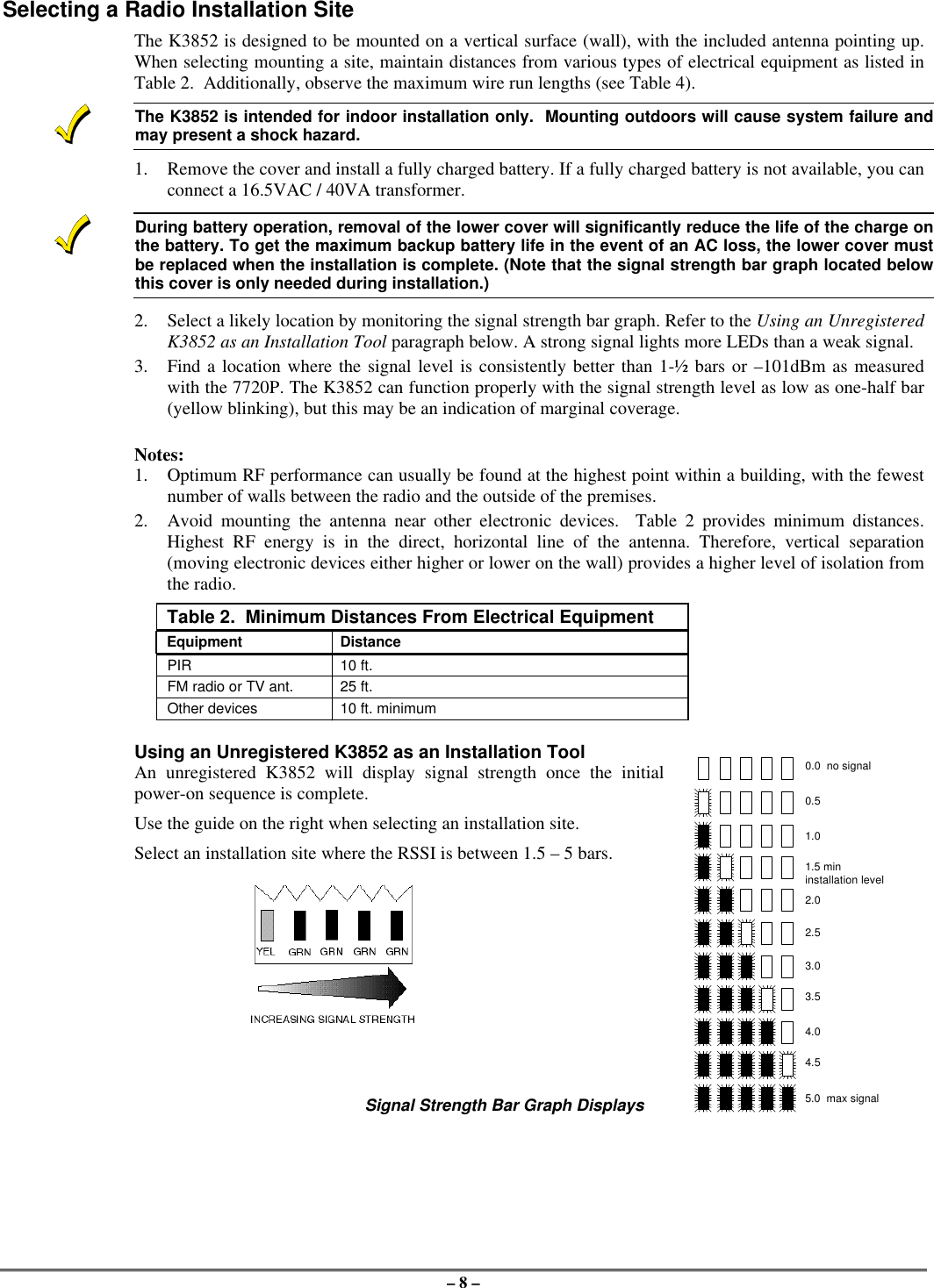
– 8 –Selecting a Radio Installation SiteThe K3852 is designed to be mounted on a vertical surface (wall), with the included antenna pointing up.When selecting mounting a site, maintain distances from various types of electrical equipment as listed inTable 2.  Additionally, observe the maximum wire run lengths (see Table 4).The K3852 is intended for indoor installation only.  Mounting outdoors will cause system failure andmay present a shock hazard.1. Remove the cover and install a fully charged battery. If a fully charged battery is not available, you canconnect a 16.5VAC / 40VA transformer.During battery operation, removal of the lower cover will significantly reduce the life of the charge onthe battery. To get the maximum backup battery life in the event of an AC loss, the lower cover mustbe replaced when the installation is complete. (Note that the signal strength bar graph located belowthis cover is only needed during installation.)2. Select a likely location by monitoring the signal strength bar graph. Refer to the Using an UnregisteredK3852 as an Installation Tool paragraph below. A strong signal lights more LEDs than a weak signal.3. Find a location where the signal level is consistently better than 1-½ bars or –101dBm as measuredwith the 7720P. The K3852 can function properly with the signal strength level as low as one-half bar(yellow blinking), but this may be an indication of marginal coverage.Notes:1. Optimum RF performance can usually be found at the highest point within a building, with the fewestnumber of walls between the radio and the outside of the premises.2. Avoid mounting the antenna near other electronic devices.  Table 2 provides minimum distances.Highest RF energy is in the direct, horizontal line of the antenna. Therefore, vertical separation(moving electronic devices either higher or lower on the wall) provides a higher level of isolation fromthe radio.Table 2.  Minimum Distances From Electrical EquipmentEquipment DistancePIR 10 ft.FM radio or TV ant. 25 ft.Other devices 10 ft. minimumUsing an Unregistered K3852 as an Installation ToolAn unregistered K3852 will display signal strength once the initialpower-on sequence is complete.Use the guide on the right when selecting an installation site.Select an installation site where the RSSI is between 1.5 – 5 bars.Signal Strength Bar Graph Displays0.0  no signal0.51.02.02.53.03.54.04.55.0  max signal1.5 mininstallation level
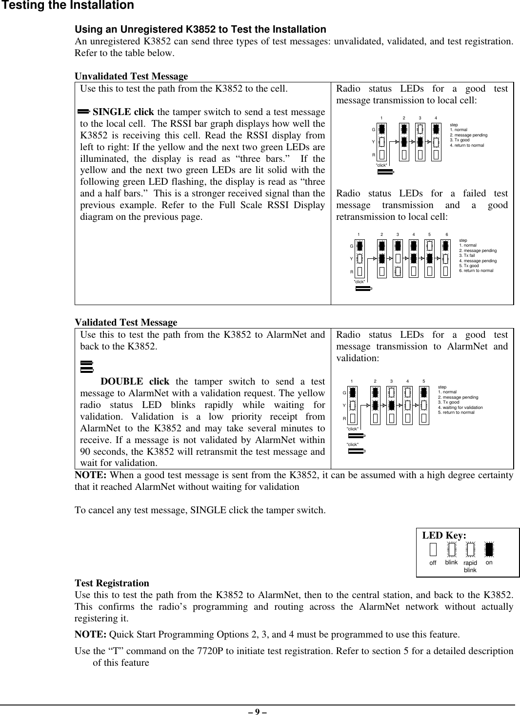
– 9 –Testing the InstallationUsing an Unregistered K3852 to Test the InstallationAn unregistered K3852 can send three types of test messages: unvalidated, validated, and test registration.Refer to the table below.Unvalidated Test MessageUse this to test the path from the K3852 to the cell.     SINGLE click the tamper switch to send a test messageto the local cell.  The RSSI bar graph displays how well theK3852 is receiving this cell. Read the RSSI display fromleft to right: If the yellow and the next two green LEDs areilluminated, the display is read as “three bars.”  If theyellow and the next two green LEDs are lit solid with thefollowing green LED flashing, the display is read as “threeand a half bars.”  This is a stronger received signal than theprevious example. Refer to the Full Scale RSSI Displaydiagram on the previous page.Radio status LEDs for a good testmessage transmission to local cell:Radio status LEDs for a failed testmessage transmission and a goodretransmission to local cell:Validated Test MessageUse this to test the path from the K3852 to AlarmNet andback to the K3852.        DOUBLE click the tamper switch to send a testmessage to AlarmNet with a validation request. The yellowradio status LED blinks rapidly while waiting forvalidation. Validation is a low priority receipt fromAlarmNet to the K3852 and may take several minutes toreceive. If a message is not validated by AlarmNet within90 seconds, the K3852 will retransmit the test message andwait for validation.Radio status LEDs for a good testmessage transmission to AlarmNet andvalidation:NOTE: When a good test message is sent from the K3852, it can be assumed with a high degree certaintythat it reached AlarmNet without waiting for validationTo cancel any test message, SINGLE click the tamper switch.LED Key:off blink rapidblinkonTest RegistrationUse this to test the path from the K3852 to AlarmNet, then to the central station, and back to the K3852.This confirms the radio’s programming and routing across the AlarmNet network without actuallyregistering it.NOTE: Quick Start Programming Options 2, 3, and 4 must be programmed to use this feature.Use the “T” command on the 7720P to initiate test registration. Refer to section 5 for a detailed descriptionof this feature"click"GYR1 2 3 4step1. normal2. message pending3. Tx good4. return to normal"click"GYR234step1. normal2. message pending3. Tx fail4. message pending5. Tx good6. return to normal1 5 6"click"GYR1 2 3 4step1. normal2. message pending3. Tx good4. waiting for validation5. return to normal"click"5
– 10 –  Section 4: Programming the K3852There are 3 methods of programming the K3852: (1) Using a 7720P Programming Tool; (2) using an ECPcapable control panel that supports long range radio programming,; (3) using the ProgrammerlessRegistration Option (PRO).To use the 7720P, connect the 7720P then power-up the radio. Refer to the description below.To use an ECP capable control, connect the control, then power-up the radio. Select ECP operation bypressing the tamper switch once while the radio status LEDs are flashing in unison, which toggles thedefault configuration from zone mode to ECP mode. The unprogrammed K3852 flashes the radio statusLEDs as follows during initial power-up:ECP mode = twice per secondZone mode = once per secondThe default device address of the radio is 3. Refer to the control’s instructions for programming procedures.To use the Programmerless Registration Option, power-up the radio, then contact AlarmNet TechnicalAssistance Center (TAC). Refer to the Programmerless Registration Option Installation and ProgrammingGuide insert.Using a 7720P Programming ToolThe 7720P Programming Tool is powered by the K3852 via the Programming Jack. The K3852 willautomatically sense the presence of the 7720P when it is plugged in.Each key of the 7720P has two possible functions: a normal function and a SHIFT function. To perform anormal key function, simply press the desired key. To perform a SHIFT key function, press the SHIFT key,then press desired function key.Table 3. 7720P Normal & Shift Key (shift LED lit) Functions   Key Normal Key Function SHIFT Key FunctionBS/ESC [BS]: Press to delete entry [ESC]: Press to quit program mode;also can reset EEPROM defaults*↓/↑[↓]: Scroll down programming [↑]: Scroll up programmingN/Y [N]: Press for "NO" answer  [Y]: Press SHIFT-Y for "YES" answerSHIFT Press before pressing a SHIFT key function. Will light SHIFT LED. LEDgoes out once a key is pressed. Press again for each SHIFT function desired.1/A [1]: For entering the number 1 [A]: For entering letter A2/B [2]: For entering the number 2 [B]: For entering letter B3/C [3]: For entering the number 3 [C]: For entering letter C4/D [4]: For entering the number 4 [D]: For entering letter D5/E [5]: For entering the number 5 [E]: For entering letter E6/F [6]: For entering the number 6 [F]: For entering letter F7/S [7]: For entering the number 7 [S]: For entering letter S8/T [8]: For entering the number 8 [T]: For entering letter T9/X [9]: For entering the number 9 [X]: For entering letter X*/SPACE [*]: For scrolling option list [SPACE]: For scrolling option list0[0]: For entering the number 0 No SHIFT function #/ENTER [#/ENTER]: Press to accept entries No SHIFT function* Active only when the "REVIEW?" prompt is displayed.After connecting the 7720P cable, power up the K3852 .  The following will be displayed:K3852 x.xx(c) Pittway 1999x.xx = current software revision level   NOTE: This document applies to software Rev. 1.20 or higherAt this prompt during initial power-up, you may proceed with programming the K3852. Programming isaccomplished by answering displayed questions.  Most questions require only a [Y]es or [N]o response,while others require a numerical response (ID numbers, etc.).  Press ENTER to accept each response andproceed to the next question.  A "?" indicates an invalid entry.  The current value is displayed on the secondline in parentheses ( ).  To accept the current entry, simply press the ENTER key.  If the current value is aninvalid entry, pressing the enter key will cause the display to repeat the unanswered question; the nextquestion will not be displayed until a valid answer is entered.  Use the UP/DOWN arrow keys to scrollthrough the programming questions without changing any values.  The ESC key will bring the list ofquestions to the end.
– 11 –Enter programming mode by pressing [ENTER] during the initial power-up period after the chasersequence (while radio status LEDs are flashing consecutively or in unison).The K3852 reads its EEROM to determine its preprogrammed parameters.  A CRC of the EEROMlocations is also read.  If the computed CRC does not match the one read from EEROM, or if theprogramming parameters are invalid, the 7720P LCD displays "NO PROG" and the radio status LEDs flashin unison (after the initial chaser sequence). Otherwise, the LEDs flash consecutively.Password ProtectionIf you are NOT programming the radio through an ECP capable control panel (e.g., VISTA-128FB), theprogramming menu can be password protectedOnce a password is assigned, the following prompt appears upon entering programming mode:ENTER PASSWORD:See “Exiting Program Mode” paragraph later in this section for assigning and changing passwords.Subscriber Information (Questions 1-7)Question 1*. ECP Radio(Y/N) Press “Y” to enable ECP communication for alarm input (check thatjumper P3 is to right). Press “N” to enable voltage triggers for alarminput.* This question will NOT appear if you are programming via the controlpanel, since ECP mode is automatically required; Question 2 will be thefirst programming option displayed on the keypad.Question 2. ID # Enter the 4-digit customer account number, 0001-9999.Question 3. City Enter the 2-digit primary city code, 01-99 (decimal).Question 4. CS ID Enter the primary central station's system ID number, 01-FE.Question 5. Supervision(24Hr.)This selection sets the supervision timing for the K3852 for either 24hour or weekly. The default supervision timing is 24 hours. The K3852sends a supervision message once during the supervision period.AlarmNet transmits a communications failure alarm to the central stationif the supervision message is not heard within the period.Use the Space key to select weekly or 24 hour supervision.Must be set to 24 hr for UL installations.Question 6. Time Zone(Eastern)Use the [*] key to select the time zone in which the K3852 is beinginstalled: Eastern, Central, Mountain, Pacific, or Atlantic.Question 7. Carrier Select(Auto)Use the [*] key to choose the method by which the K3852 will select itscellular carrier: “A” or “B” side.Auto:  K3852 selects the carrier to which it will connect.  In this mode,the K3852 will automatically change its carrier side if coveragebecomes degraded.NOTE: If the K3852 had been operating and competed itsinitialization sequence with this option set to “auto,” one of thefollowing prompts will appear:Auto B then A: shows that the B-side carrier was initially selected.Auto A then B: shows that the A-side carrier was initially selected.These prompts are displays only, not programming choices, andthe prompt will disappear if the [*] key is pressed.A then B: K3852 prefers connecting to the “A” side carrier rather than the“B” side carrier.  If coverage is lost on the A side, the radio willswitch to the “B” side carrier.B then A: K3852 prefers connecting to the “B” side carrier rather than the“A” side carrier.  If coverage is lost on the B side, the radio willswitch to the “A” side carrier.A Only: K3852 searches for coverage on the “A” side only. Fixed carrieroperation.B Only: K3852 searches for coverage on the “B” side only.  Fixed carrieroperation.
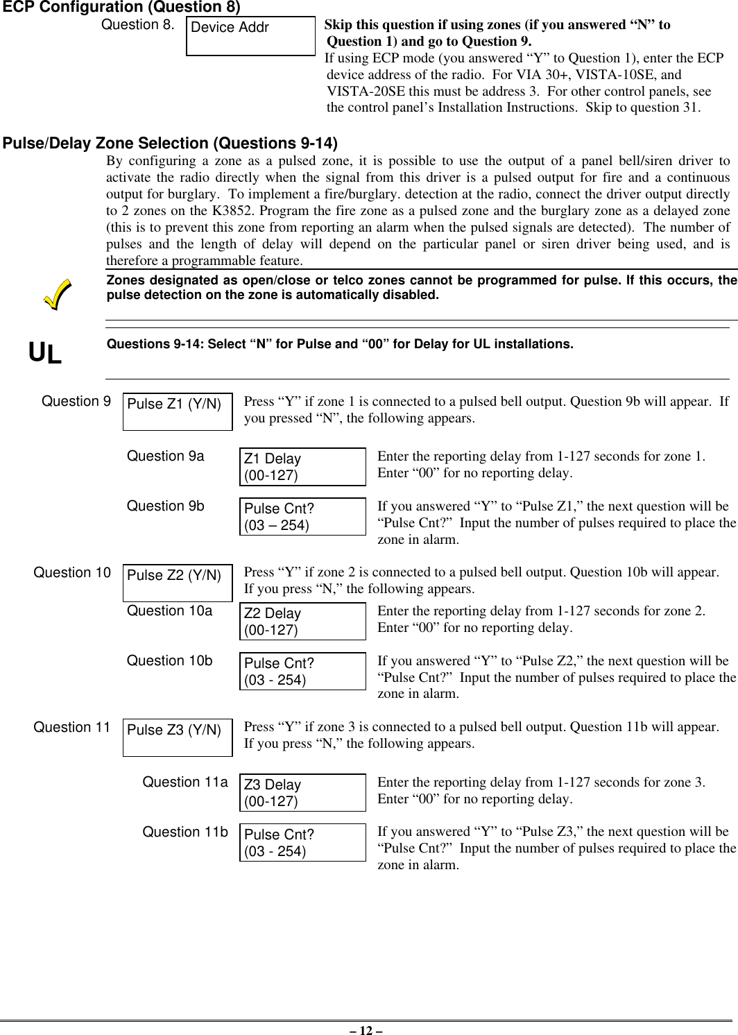
– 12 –ECP Configuration (Question 8)Question 8. Device Addr Skip this question if using zones (if you answered “N” toQuestion 1) and go to Question 9.If using ECP mode (you answered “Y” to Question 1), enter the ECPdevice address of the radio.  For VIA 30+, VISTA-10SE, andVISTA-20SE this must be address 3.  For other control panels, seethe control panel’s Installation Instructions.  Skip to question 31.Pulse/Delay Zone Selection (Questions 9-14)By configuring a zone as a pulsed zone, it is possible to use the output of a panel bell/siren driver toactivate the radio directly when the signal from this driver is a pulsed output for fire and a continuousoutput for burglary.  To implement a fire/burglary. detection at the radio, connect the driver output directlyto 2 zones on the K3852. Program the fire zone as a pulsed zone and the burglary zone as a delayed zone(this is to prevent this zone from reporting an alarm when the pulsed signals are detected).  The number ofpulses and the length of delay will depend on the particular panel or siren driver being used, and istherefore a programmable feature.Zones designated as open/close or telco zones cannot be programmed for pulse. If this occurs, thepulse detection on the zone is automatically disabled.ULQuestions 9-14: Select “N” for Pulse and “00” for Delay for UL installations.Question 9 Pulse Z1 (Y/N) Press “Y” if zone 1 is connected to a pulsed bell output. Question 9b will appear.  Ifyou pressed “N”, the following appears.Question 9a Z1 Delay(00-127)Enter the reporting delay from 1-127 seconds for zone 1.Enter “00” for no reporting delay.Question 9b Pulse Cnt?(03 – 254)If you answered “Y” to “Pulse Z1,” the next question will be“Pulse Cnt?”  Input the number of pulses required to place thezone in alarm.Question 10 Pulse Z2 (Y/N) Press “Y” if zone 2 is connected to a pulsed bell output. Question 10b will appear.If you press “N,” the following appears.Question 10a Z2 Delay(00-127)Enter the reporting delay from 1-127 seconds for zone 2.Enter “00” for no reporting delay.Question 10b Pulse Cnt?(03 - 254)If you answered “Y” to “Pulse Z2,” the next question will be“Pulse Cnt?”  Input the number of pulses required to place thezone in alarm.Question 11 Pulse Z3 (Y/N) Press “Y” if zone 3 is connected to a pulsed bell output. Question 11b will appear.If you press “N,” the following appears.Question 11a Z3 Delay(00-127)Enter the reporting delay from 1-127 seconds for zone 3.Enter “00” for no reporting delay.Question 11b Pulse Cnt?(03 - 254)If you answered “Y” to “Pulse Z3,” the next question will be“Pulse Cnt?”  Input the number of pulses required to place thezone in alarm.
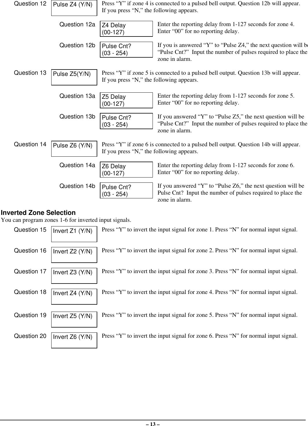
– 13 –Question 12 Pulse Z4 (Y/N) Press “Y” if zone 4 is connected to a pulsed bell output. Question 12b will appear.If you press “N,” the following appears.Question 12a Z4 Delay(00-127)Enter the reporting delay from 1-127 seconds for zone 4.Enter “00” for no reporting delay.Question 12b Pulse Cnt?(03 - 254)If you is answered “Y” to “Pulse Z4,” the next question will be“Pulse Cnt?”  Input the number of pulses required to place thezone in alarm.Question 13 Pulse Z5(Y/N) Press “Y” if zone 5 is connected to a pulsed bell output. Question 13b will appear.If you press “N,” the following appears.Question 13a Z5 Delay(00-127)Enter the reporting delay from 1-127 seconds for zone 5.Enter “00” for no reporting delay.Question 13b Pulse Cnt?(03 - 254)If you answered “Y” to “Pulse Z5,” the next question will be“Pulse Cnt?”  Input the number of pulses required to place thezone in alarm.Question 14 Pulse Z6 (Y/N) Press “Y” if zone 6 is connected to a pulsed bell output. Question 14b will appear.If you press “N,” the following appears.Question 14a Z6 Delay(00-127)Enter the reporting delay from 1-127 seconds for zone 6.Enter “00” for no reporting delay.Question 14b Pulse Cnt?(03 - 254)If you answered “Y” to “Pulse Z6,” the next question will bePulse Cnt?  Input the number of pulses required to place thezone in alarm.Inverted Zone SelectionYou can program zones 1-6 for inverted input signals.Question 15 Invert Z1 (Y/N) Press “Y” to invert the input signal for zone 1. Press “N” for normal input signal.Question 16 Invert Z2 (Y/N) Press “Y” to invert the input signal for zone 2. Press “N” for normal input signal.Question 17 Invert Z3 (Y/N) Press “Y” to invert the input signal for zone 3. Press “N” for normal input signal.Question 18 Invert Z4 (Y/N) Press “Y” to invert the input signal for zone 4. Press “N” for normal input signal.Question 19 Invert Z5 (Y/N) Press “Y” to invert the input signal for zone 5. Press “N” for normal input signal.Question 20 Invert Z6 (Y/N) Press “Y” to invert the input signal for zone 6. Press “N” for normal input signal.
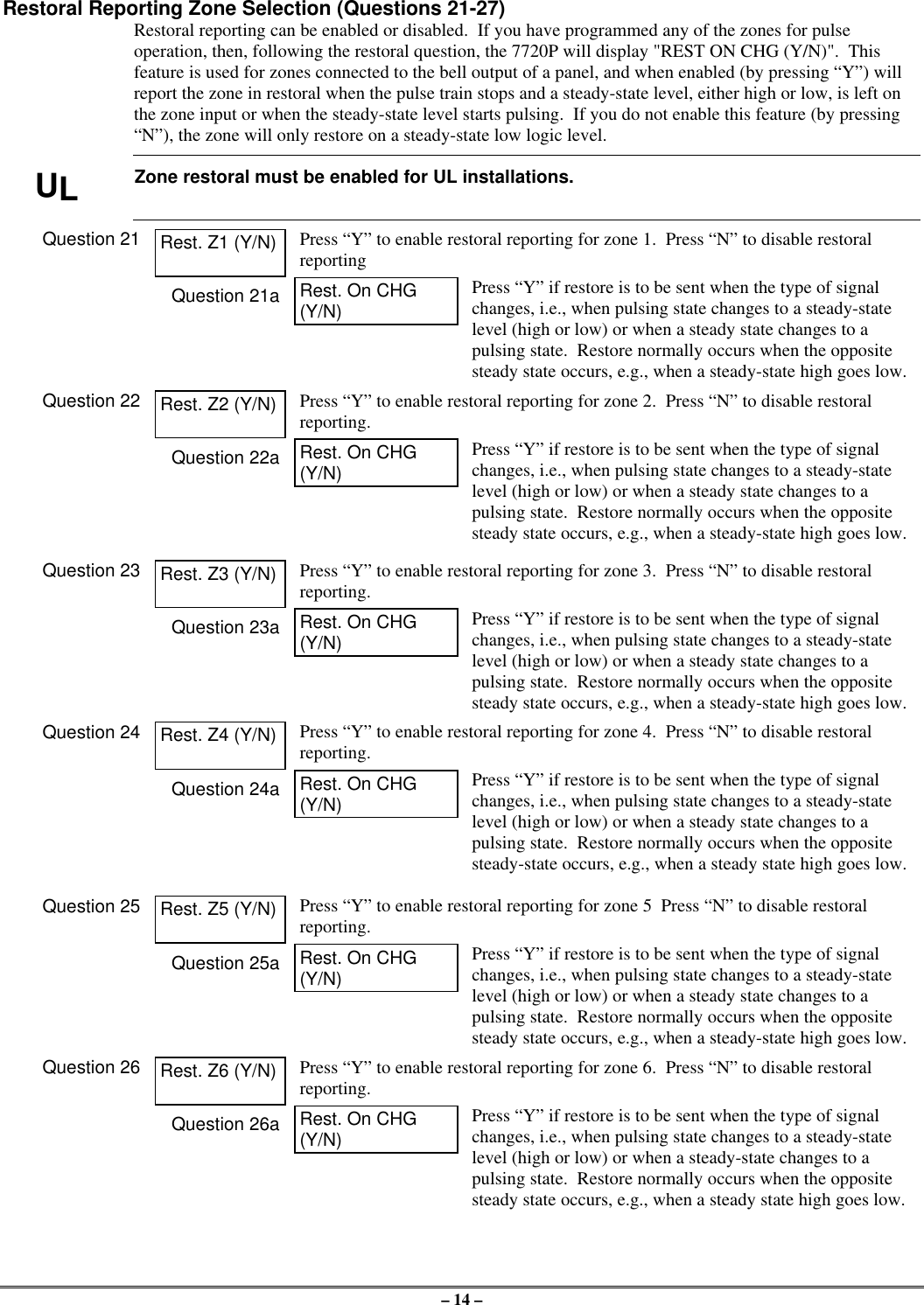
– 14 –Restoral Reporting Zone Selection (Questions 21-27)Restoral reporting can be enabled or disabled.  If you have programmed any of the zones for pulseoperation, then, following the restoral question, the 7720P will display "REST ON CHG (Y/N)".  Thisfeature is used for zones connected to the bell output of a panel, and when enabled (by pressing “Y”) willreport the zone in restoral when the pulse train stops and a steady-state level, either high or low, is left onthe zone input or when the steady-state level starts pulsing.  If you do not enable this feature (by pressing“N”), the zone will only restore on a steady-state low logic level.ULZone restoral must be enabled for UL installations.Question 21 Rest. Z1 (Y/N) Press “Y” to enable restoral reporting for zone 1.  Press “N” to disable restoralreportingQuestion 21a Rest. On CHG(Y/N)Press “Y” if restore is to be sent when the type of signalchanges, i.e., when pulsing state changes to a steady-statelevel (high or low) or when a steady state changes to apulsing state.  Restore normally occurs when the oppositesteady state occurs, e.g., when a steady-state high goes low.Question 22 Rest. Z2 (Y/N) Press “Y” to enable restoral reporting for zone 2.  Press “N” to disable restoralreporting.Question 22a Rest. On CHG(Y/N)Press “Y” if restore is to be sent when the type of signalchanges, i.e., when pulsing state changes to a steady-statelevel (high or low) or when a steady state changes to apulsing state.  Restore normally occurs when the oppositesteady state occurs, e.g., when a steady-state high goes low.Question 23 Rest. Z3 (Y/N) Press “Y” to enable restoral reporting for zone 3.  Press “N” to disable restoralreporting.Question 23a Rest. On CHG(Y/N)Press “Y” if restore is to be sent when the type of signalchanges, i.e., when pulsing state changes to a steady-statelevel (high or low) or when a steady state changes to apulsing state.  Restore normally occurs when the oppositesteady state occurs, e.g., when a steady-state high goes low.Question 24 Rest. Z4 (Y/N) Press “Y” to enable restoral reporting for zone 4.  Press “N” to disable restoralreporting.Question 24a Rest. On CHG(Y/N)Press “Y” if restore is to be sent when the type of signalchanges, i.e., when pulsing state changes to a steady-statelevel (high or low) or when a steady state changes to apulsing state.  Restore normally occurs when the oppositesteady-state occurs, e.g., when a steady state high goes low.Question 25 Rest. Z5 (Y/N) Press “Y” to enable restoral reporting for zone 5  Press “N” to disable restoralreporting.Question 25a Rest. On CHG(Y/N)Press “Y” if restore is to be sent when the type of signalchanges, i.e., when pulsing state changes to a steady-statelevel (high or low) or when a steady state changes to apulsing state.  Restore normally occurs when the oppositesteady state occurs, e.g., when a steady-state high goes low.Question 26 Rest. Z6 (Y/N) Press “Y” to enable restoral reporting for zone 6.  Press “N” to disable restoralreporting.Question 26a Rest. On CHG(Y/N)Press “Y” if restore is to be sent when the type of signalchanges, i.e., when pulsing state changes to a steady-statelevel (high or low) or when a steady-state changes to apulsing state.  Restore normally occurs when the oppositesteady state occurs, e.g., when a steady state high goes low.
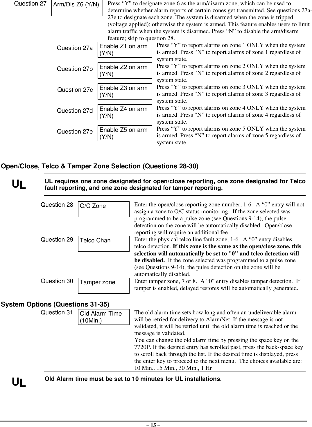
– 15 –Question 27 Arm/Dis Z6 (Y/N) Press “Y” to designate zone 6 as the arm/disarm zone, which can be used todetermine whether alarm reports of certain zones get transmitted. See questions 27a-27e to designate each zone. The system is disarmed when the zone is tripped(voltage applied); otherwise the system is armed. This feature enables users to limitalarm traffic when the system is disarmed. Press “N” to disable the arm/disarmfeature; skip to question 28.Question 27a Enable Z1 on arm(Y/N)Press “Y” to report alarms on zone 1 ONLY when the systemis armed. Press “N” to report alarms of zone 1 regardless ofsystem state.Question 27b Enable Z2 on arm(Y/N)Press “Y” to report alarms on zone 2 ONLY when the systemis armed. Press “N” to report alarms of zone 2 regardless ofsystem state.Question 27c Enable Z3 on arm(Y/N)Press “Y” to report alarms on zone 3 ONLY when the systemis armed. Press “N” to report alarms of zone 3 regardless ofsystem state.Question 27d Enable Z4 on arm(Y/N)Press “Y” to report alarms on zone 4 ONLY when the systemis armed. Press “N” to report alarms of zone 4 regardless ofsystem state.Question 27e Enable Z5 on arm(Y/N)Press “Y” to report alarms on zone 5 ONLY when the systemis armed. Press “N” to report alarms of zone 5 regardless ofsystem state.Open/Close, Telco & Tamper Zone Selection (Questions 28-30)ULUL requires one zone designated for open/close reporting, one zone designated for Telcofault reporting, and one zone designated for tamper reporting.Question 28 O/C Zone Enter the open/close reporting zone number, 1-6.  A “0” entry will notassign a zone to O/C status monitoring.  If the zone selected wasprogrammed to be a pulse zone (see Questions 9-14), the pulsedetection on the zone will be automatically disabled.  Open/closereporting will require an additional fee.Question 29 Telco Chan Enter the physical telco line fault zone, 1-6.  A “0” entry disablestelco detection. If this zone is the same as the open/close zone, thisselection will automatically be set to "0" and telco detection willbe disabled.  If the zone selected was programmed to a pulse zone(see Questions 9-14), the pulse detection on the zone will beautomatically disabled.Question 30 Tamper zone Enter tamper zone, 7 or 8.  A “0” entry disables tamper detection.  Iftamper is enabled, delayed restores will be automatically generated.System Options (Questions 31-35)Question 31 Old Alarm Time(10Min.)The old alarm time sets how long and often an undeliverable alarmwill be retried for delivery to AlarmNet. If the message is notvalidated, it will be retried until the old alarm time is reached or themessage is validated.You can change the old alarm time by pressing the space key on the7720P. If the desired entry has scrolled past, press the back-space keyto scroll back through the list. If the desired time is displayed, pressthe enter key to proceed to the next menu.  The choices available are:10 Min., 15 Min., 30 Min., 1 HrULOld Alarm time must be set to 10 minutes for UL installations.
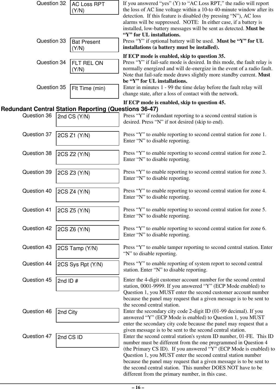
– 16 –Question 32 AC Loss RPT(Y/N)If you answered “yes” (Y) to “AC Loss RPT,” the radio will reportthe loss of AC line voltage within a 10-to 40-minute window after itsdetection.  If this feature is disabled (by pressing “N”), AC lossalarms will be suppressed.  NOTE:  In either case, if a battery isinstalled, low-battery messages will be sent as detected. Must be“Y” for UL installations.Question 33 Bat Present(Y/N)Press “Y” if optional battery will be used.  Must be “Y” for ULinstallations (a battery must be installed).If ECP mode is enabled, skip to question 35.Question 34 FLT REL ON(Y/N)Press “Y” if fail-safe mode is desired. In this mode, the fault relay isnormally energized and will de-energize in the event of a radio fault.Note that fail-safe mode draws slightly more standby current. Mustbe “Y” for UL installations.Question 35 Flt Time (min) Enter in minutes 1 - 99 the time delay before the fault relay willchange state, after a loss of contact with the network.If ECP mode is enabled, skip to question 45.Redundant Central Station Reporting (Questions 36-47)Question 36 2nd CS (Y/N) Press “Y” if redundant reporting to a second central station isdesired. Press “N” if not desired (skip to end).Question 37 2CS Z1 (Y/N) Press “Y” to enable reporting to second central station for zone 1.Enter “N” to disable reporting.Question 38 2CS Z2 (Y/N) Press “Y” to enable reporting to second central station for zone 2.Enter “N” to disable reporting.Question 39 2CS Z3 (Y/N) Press “Y” to enable reporting to second central station for zone 3.Enter “N” to disable reporting.Question 40 2CS Z4 (Y/N) Press “Y” to enable reporting to second central station for zone 4.Enter “N” to disable reporting.Question 41 2CS Z5 (Y/N) Press “Y” to enable reporting to second central station for zone 5.Enter “N” to disable reporting.Question 42 2CS Z6 (Y/N) Press “Y” to enable reporting to second central station for zone 6.Enter “N” to disable reporting.Question 43 2CS Tamp (Y/N) Press “Y” to enable tamper reporting to second central station. Enter“N” to disable reporting.Question 44 2CS Sys Rpt (Y/N) Press “Y” to enable reporting of system report to second centralstation. Enter “N” to disable reporting.Question 45 2nd ID # Enter the 4-digit customer account number for the second centralstation, 0001-9999. If you answered “Y” (ECP Mode enabled) toQuestion 1, you MUST enter the second customer account numberbecause the panel may request that a given message is to be sent tothe second central station.Question 46 2nd City Enter the secondary city code 2-digit ID (01-99 decimal). If youanswered “Y” (ECP Mode is enabled) to Question 1, you MUSTenter the secondary city code because the panel may request that agiven message is to be sent to the second central station.Question 47 2nd CS ID Enter the second central station's system ID number, 01-FE.  This IDnumber must be different from the one programmed in Question 4(the Primary CS ID).  If you answered “Y” (ECP Mode is enabled) toQuestion 1, you MUST enter the second central station numberbecause the panel may request that a given message is to be sent tothe second central station.  This number DOES NOT have to bedifferent from the primary number, in this case.
– 17 –Exiting Program Mode, Setting Defaults & Assigning PasswordsWhen the last question is answered, the system validates all entries. If no errors are found, the following isdisplayed:REVIEW?To review the programming options (to ensure that the correct responses have been made), press “Y.” Theprogramming questions will be displayed again, starting with Question 1. Use the UP/DOWN arrow keysto scroll through the program fields without changing any of the values. If a value requires change, simplytype in the correct value. When the last field is displayed, the “REVIEW?” question again appears.Setting Factory Defaults: You can reset the programming options globally to their factory default valuesby pressing ESC at the “REVIEW?” prompt. A confirmation prompt will appear. Press “Y” to reset, orpress “N” to cancel this function. If you press “Y,” all programmed values will be reset to their originalfactory settings.To exit program mode and assign passwords, press “N” in response to the “REVIEW?” question.  If youare NOT programming the radio through a panel and no password has been assigned, the followingappears:ENTER PASSWORD?[Y/N]Passwords can be used to split the programming questions intotwo menus. See the “Password Protection” paragraph earlier inthis section. If a password is desired, press “Y”. The followingprompts appear. Press “N” if no passwords are desired.If a password has already been assigned for the current programming menu, the “ENTER PASSWORD?”prompt is replaced by the following:CHG PASSWORD?[Y/N]Press “Y” or “N,” depending on whether you want to change thepassword for the current programming menu. If [Y]es, you willbe prompted to enter the new password twice (as confirmation).To clear an existing password, answer "Y" to the "CHGPASSWORD" prompt, but press only the ENTER key whenprompted for the new password and its confirmation.ENTER PASSWORD: Enter the 4-digit password.VERIFY PASSWORD: Reenter the 4-digit password as confirmation.When the password question(s) have been answered, the system exits program mode and returns to normalmode. You can then disconnect the programming tool, or use it to trigger test messages. Refer to Testingthe System section.
– 18 –Section 5: RegistrationTest RegistrationPrior to registering the radio, a test registration can be sent. The test registration is used to confirm theprogramming of the radio and the routing across the AlarmNet C network without actually registering theradio. This feature requires a 7720P.To initiate a test registration, first complete Quick Start programming. Options 2, 3, and 4 must beprogrammed. After this, press shift-“T” on a connected 7720P. Test registration progress messages will bedisplayed on the 7720P as described in the Interactive Registration paragraph below. When a testregistration has been completed, the radio will be reported to the central station as 5555 5555 9. Thisindicates that the radio is programmed and routed correctly, but is not registered. If test registration fails, amessage on the 7720P will indicate the failure.Registering the RadioOnce you have initialized and programmed the K3852, you must register it with AlarmNet Control.  Anunregistered K3852 is indicated on the radio status LEDs as: solid green, blinking yellow, and unlit red.The registration process consists of transmitting 3 messages in succession and receiving a registrationvalidation from AlarmNet Control.  It can take several minutes to complete.Initiate the registration sequence by either clicking the tamper switch 3 times or by pressing shift and the uparrow [↑] on the 7720P. If you are using a 7720P, skip to the Interactive Registration section.You can monitor the registration process on the RSSI display as follows: yellow LED will be blinking andthe green LED at the extreme right of the display will blink.  When this green LED lights solid, the nextgreen LED to the left begins to blink.  When this LED lights solid, the next green LED begins to blink, andso on, until all 4 green LEDs are lit solid.Once you have successfully completed the registration, the radio will enter normal operating mode; thegreen radio status LED extinguishes, the yellow radio status LED continues normal blinking, and the RSSIdisplay indicates received signal strength.If registration is not validated within 90 seconds, the K3852 will time out and all 5 RSSI LEDs will blink inunison for 30 seconds. If repeated registration attempts time out, select a new installation site.If the K3852 has been programmed with an invalid ID, city, or central station number, the registration willbe rejected. The right green LED will blink alternately with the remaining 4 RSSI LEDs.off blink rapidblinkonLED Key"click""click""click"REGISTRATIONGYRregistrationprogressYG G G GYG G G GYG G G GYG G G GMSG 1SENT MSG 2SENT MSG 3SENT WAITACK
– 19 –Interactive RegistrationThe interactive registration feature allows the installer to register the K3852 through a series of keyboardcommands on the 7720P installation tool.  This method of registration lets the installer monitor theregistration process.RegistrationMSG1  SentRegistrationMSG2  SentRegistrationMSG3  SentRegistrationWaiting for ACKOnce the installation is complete the installer should select the[↑] command on the 7720P.Three messages are sent, then the unit waits foracknowledgement.RegistrationSuccessful!If this is a new installation, and the City, CS, and Cust# havebeen correctly entered, the K3852 will be registered and thismessage will be displayed. At this point the K3852 is in fullservice and available for alarm reporting to the central station.Possible ErrorsMIN Exists This prompt may appear only if this is a test registration andindicates that a different account number is already associatedwith this MIN in the AlarmNet database.RegistrationTimed Out!If no response to the registration request is received fromAlarmNet, this message will be displayed.Reg RejectBad ID! PSIf the City, CS, and Cust# were not correctly entered, thismessage will be displayed.If this message is displayed  with a “P” primary ID, and or an “S”secondary ID, it indicates that the ID information was eitherentered in error, or the central station failed to pre-authorizeprogrammed ID numbers with AlarmNet customer service.Account ExistsSub Y/NThis prompt is displayed if this is a repair/replacement, or an errorwas made in programming the K3852 for an existing account.If this is a test registration, the opportunity to substitute the radiowill not be offered.Replacement RadiosDo You Have APIN #   Y/NAt this point the installer should havecalled in for a 4-digit alpha numeric PIN# that must be obtained by having anauthorized person call the AlarmNetTechnical Assistance Center (TAC).Answering “Y“ will continue theregistration process. Answering “N” willabort the process. If  “Y” was selectedthen the next prompt will be displayed.
– 20 –Alarm Will BeSent, OK  Y/NIf the installer proceeds beyond thispoint  by answering “Y,” a correct PINnumber must be supplied to completethe registration. Any attempt atregistration at this point, whethersuccessful or unsuccessful, will result ina radio substitution alarm being sent tothe CS. Answering “Y” allows theinstaller to continue registration.Answering “N” will abort the registration.If “Y” was chosen, see the next section onReplacement Radios for the remainder ofthe process.If the installation is a known repair/replacement, you can skip the previous section by selecting the[↓] command to initiate the replacement registration process, beginning with the PIN entry asfollows.Enter PIN# The installer must enter a 4 digit alphanumeric PIN # that must be obtained byhaving an authorized person call theAlarmNet TAC (Technical AssistanceCenter). The PIN should  be entered,followed by the enter key.RegistrationMSG1  SentRegistrationMSG2  SentRegistrationMSG3  SentRegistrationWaiting for ACKThree messages are sent, then the unitwaits for acknowledgement.RegistrationSuccessful!If the PIN is valid, the new K3852 willregister and the old unit will beunregistered. A radio substitution alarm willbe sent to the central station by AlarmNet.RegistrationCanceled!If at any point in the substitution processthe installer chooses not to register theK3852, this is the displayed message.SubstitutionRejected!If an invalid PIN was entered this is thedisplay message, and the registrationprocess will be aborted and will need tobe started from the beginning. Note thateach attempt will cause a radiosubstitution alarm to be sent to the centralstation.
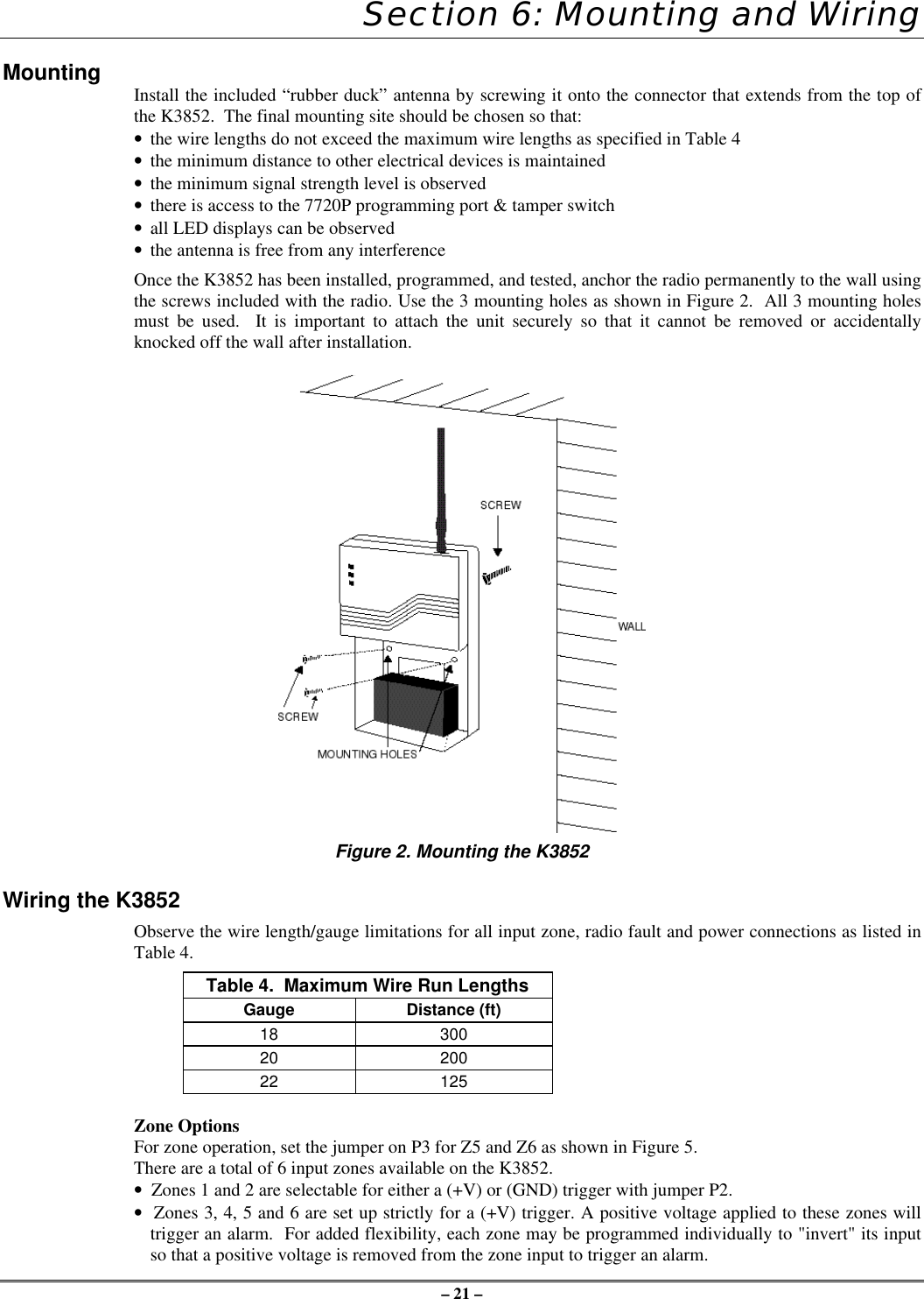
– 21 –Section 6: Mounting and WiringMounting Install the included “rubber duck” antenna by screwing it onto the connector that extends from the top ofthe K3852.  The final mounting site should be chosen so that:• the wire lengths do not exceed the maximum wire lengths as specified in Table 4• the minimum distance to other electrical devices is maintained• the minimum signal strength level is observed• there is access to the 7720P programming port & tamper switch• all LED displays can be observed• the antenna is free from any interferenceOnce the K3852 has been installed, programmed, and tested, anchor the radio permanently to the wall usingthe screws included with the radio. Use the 3 mounting holes as shown in Figure 2.  All 3 mounting holesmust be used.  It is important to attach the unit securely so that it cannot be removed or accidentallyknocked off the wall after installation.Figure 2. Mounting the K3852Wiring the K3852Observe the wire length/gauge limitations for all input zone, radio fault and power connections as listed inTable 4.Table 4.  Maximum Wire Run LengthsGauge Distance (ft)18 30020 20022 125Zone OptionsFor zone operation, set the jumper on P3 for Z5 and Z6 as shown in Figure 5.There are a total of 6 input zones available on the K3852.•  Zones 1 and 2 are selectable for either a (+V) or (GND) trigger with jumper P2.•  Zones 3, 4, 5 and 6 are set up strictly for a (+V) trigger. A positive voltage applied to these zones willtrigger an alarm.  For added flexibility, each zone may be programmed individually to "invert" its inputso that a positive voltage is removed from the zone input to trigger an alarm.
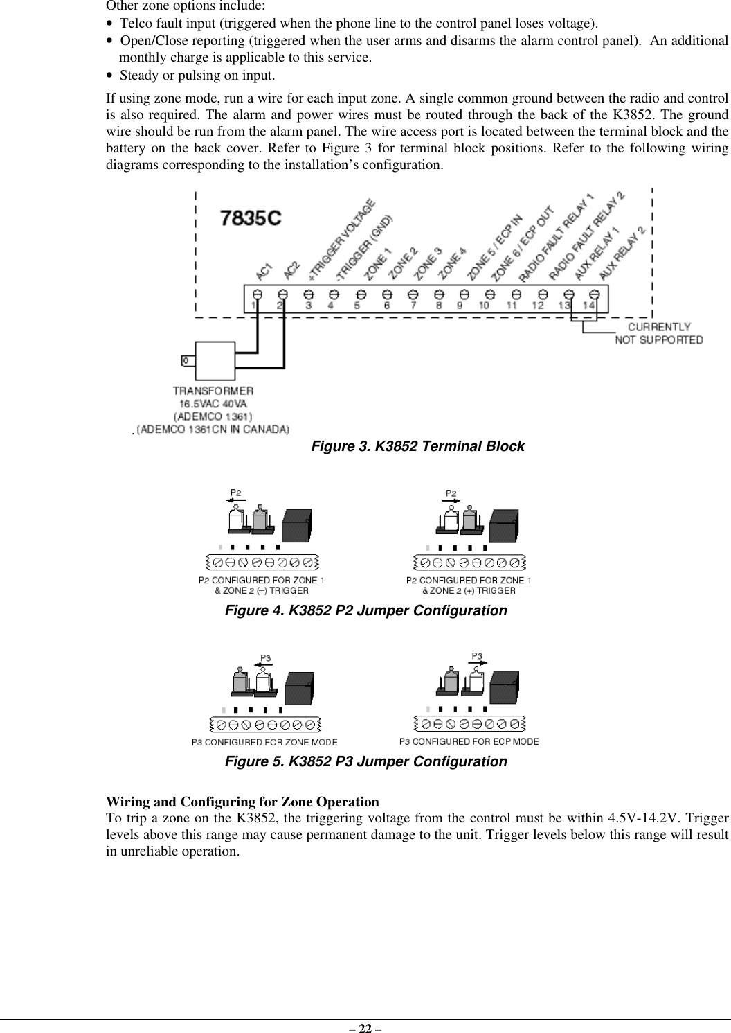
– 22 –Other zone options include:•  Telco fault input (triggered when the phone line to the control panel loses voltage).•  Open/Close reporting (triggered when the user arms and disarms the alarm control panel).  An additionalmonthly charge is applicable to this service.•  Steady or pulsing on input.If using zone mode, run a wire for each input zone. A single common ground between the radio and controlis also required. The alarm and power wires must be routed through the back of the K3852. The groundwire should be run from the alarm panel. The wire access port is located between the terminal block and thebattery on the back cover. Refer to Figure 3 for terminal block positions. Refer to the following wiringdiagrams corresponding to the installation’s configuration.. Figure 3. K3852 Terminal BlockFigure 4. K3852 P2 Jumper ConfigurationFigure 5. K3852 P3 Jumper ConfigurationWiring and Configuring for Zone OperationTo trip a zone on the K3852, the triggering voltage from the control must be within 4.5V-14.2V. Triggerlevels above this range may cause permanent damage to the unit. Trigger levels below this range will resultin unreliable operation.
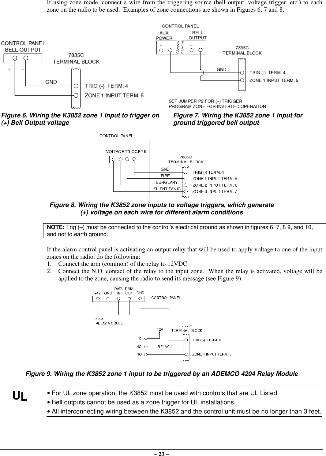
– 23 –If using zone mode, connect a wire from the triggering source (bell output, voltage trigger, etc.) to eachzone on the radio to be used.  Examples of zone connections are shown in Figures 6, 7 and 8.Figure 6. Wiring the K3852 zone 1 Input to trigger on  Figure 7. Wiring the K3852 zone 1 Input for(+) Bell Output voltage  ground triggered bell outputFigure 8. Wiring the K3852 zone inputs to voltage triggers, which generate(+) voltage on each wire for different alarm conditionsNOTE: Trig (–) must be connected to the control’s electrical ground as shown in figures 6, 7, 8 9, and 10,and not to earth ground.If the alarm control panel is activating an output relay that will be used to apply voltage to one of the inputzones on the radio, do the following:1. Connect the arm (common) of the relay to 12VDC.2. Connect the N.O. contact of the relay to the input zone.  When the relay is activated, voltage will beapplied to the zone, causing the radio to send its message (see Figure 9).Figure 9. Wiring the K3852 zone 1 input to be triggered by an ADEMCO 4204 Relay ModuleUL• For UL zone operation, the K3852 must be used with controls that are UL Listed.• Bell outputs cannot be used as a zone trigger for UL installations.• All interconnecting wiring between the K3852 and the control unit must be no longer than 3 feet.
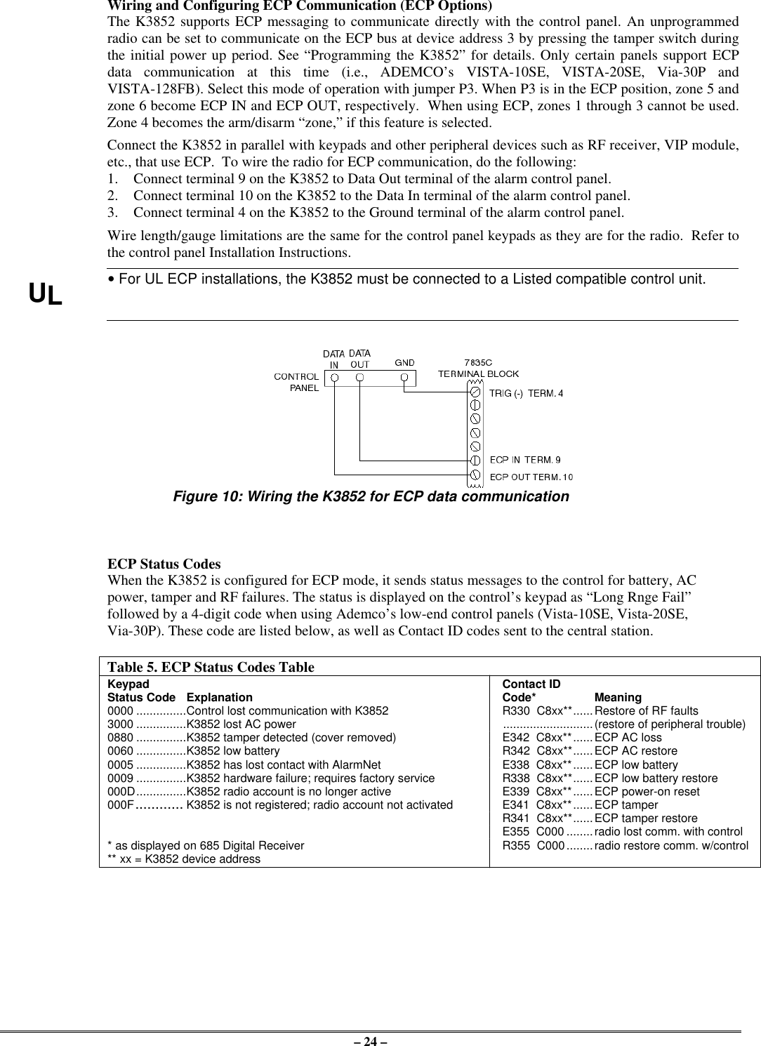
– 24 –Wiring and Configuring ECP Communication (ECP Options)The K3852 supports ECP messaging to communicate directly with the control panel. An unprogrammedradio can be set to communicate on the ECP bus at device address 3 by pressing the tamper switch duringthe initial power up period. See “Programming the K3852” for details. Only certain panels support ECPdata communication at this time (i.e., ADEMCO’s VISTA-10SE, VISTA-20SE, Via-30P andVISTA-128FB). Select this mode of operation with jumper P3. When P3 is in the ECP position, zone 5 andzone 6 become ECP IN and ECP OUT, respectively.  When using ECP, zones 1 through 3 cannot be used.Zone 4 becomes the arm/disarm “zone,” if this feature is selected.Connect the K3852 in parallel with keypads and other peripheral devices such as RF receiver, VIP module,etc., that use ECP.  To wire the radio for ECP communication, do the following:1. Connect terminal 9 on the K3852 to Data Out terminal of the alarm control panel.2. Connect terminal 10 on the K3852 to the Data In terminal of the alarm control panel.3. Connect terminal 4 on the K3852 to the Ground terminal of the alarm control panel.Wire length/gauge limitations are the same for the control panel keypads as they are for the radio.  Refer tothe control panel Installation Instructions.UL• For UL ECP installations, the K3852 must be connected to a Listed compatible control unit.Figure 10: Wiring the K3852 for ECP data communicationECP Status CodesWhen the K3852 is configured for ECP mode, it sends status messages to the control for battery, ACpower, tamper and RF failures. The status is displayed on the control’s keypad as “Long Rnge Fail”followed by a 4-digit code when using Ademco’s low-end control panels (Vista-10SE, Vista-20SE,Via-30P). These code are listed below, as well as Contact ID codes sent to the central station.Table 5. ECP Status Codes TableKeypad Contact IDStatus Code Explanation Code* Meaning0000 ...............Control lost communication with K3852 R330  C8xx**......Restore of RF faults3000 ...............K3852 lost AC power ...........................(restore of peripheral trouble)0880 ...............K3852 tamper detected (cover removed) E342  C8xx**......ECP AC loss0060 ...............K3852 low battery R342  C8xx**......ECP AC restore0005 ...............K3852 has lost contact with AlarmNet E338  C8xx**......ECP low battery0009 ...............K3852 hardware failure; requires factory service R338  C8xx**......ECP low battery restore000D...............K3852 radio account is no longer active E339  C8xx**......ECP power-on reset000F............ K3852 is not registered; radio account not activated E341  C8xx**......ECP tamperR341  C8xx**......ECP tamper restoreE355  C000 ........radio lost comm. with control* as displayed on 685 Digital Receiver R355  C000........radio restore comm. w/control** xx = K3852 device address
– 25 –Wiring for Radio FaultsYou may program the radio fault output relay (refer to Programming the K3852 section) for either:FAIL-SAFE mode (UL requirement)•Answer “Y” to “FLT REL ON (Y/N)”•Relay always energized [N.C.]•Relay will change state (and trigger a dialer, ifconnected) in the event of power loss.•Fail-safe mode increases the standby current by about10mA, which results in lower battery backup time(about 15%) in the event of power loss.LOW CURRENT mode•Answer “N” to “FLT REL ON (Y/N)”•Relay normally de-energized [N.O.]•Does not increase standby current•NOT approved for UL installations.Run two wires from the K3852’s radio fault terminals 11 and 12 to a zone on the control panel. Refer to theFigures below for wiring the radio fault relay.Figure 11.  Wiring the K3852 to trip a control panel zone  Figure 12.  Wiring the K3852 to trip aduring a radio fault (required for UL installations) control panel zone for normally open fault(not UL approved)AC Power ConnectionsPrimary power for the K3852 is provided by a wall-mounted 16.5VAC / 40VA transformer ADEMCO PN:1361 (1361CN in Canada).  Use of a transformer with a lower power rating will result in unreliable systemoperation.Connect the AC power wires from the 16.5V 40VA wall transformer to terminals 1 and 2 on the K3852. Donot plug the transformer into the AC power source until all wiring connections have been made and you areready to power up the K3852. Refer to the K3852 Initial Power-Up Sequence section.Backup Battery ConnectionThe optional battery backup (ADEMCO 7720BT) can provide over 4 hours of system life in the event of anAC power failure.  When AC power is lost, the K3852 enters a low-power state and the programmable ACloss message can alert the AlarmNet Control Center (AC loss messages are reported within 10-40 minutesof actual AC loss). Any alarms that are tripped during this low-power state will wake the system up totransmit the appropriate message.  After a successful transmission, the K3852 will reenter its low-powerstate.  When the battery reaches 10.5V, a low-battery message is transmitted, which alerts the AlarmNetControl Center that this may be the radio’s last message.  When the battery reaches 8.5V, radiotransmissions are no longer possible and the system shuts down. If AC power is restored before the systemshuts down, an AC Restore message will be sent and the battery will be recharged using the K3852’s built-in battery charger.  If AC power is restored after the system has shut down, a power-on reset conditionexists, and the radio will initialize itself as described earlier and the battery will be recharged.The K3852 performs a battery test under load on a daily basis.  During this test, if the battery drops below10.5V, a low-battery message will be generated to indicate that the battery should be replaced.To install the battery, snap it into the battery holder with the connector wire towards the lower right. Do notplug the battery in until all wiring connections have been made and you are ready to power up the K3852.Refer to K3852 Initial Power-Up Sequence section. When you are ready to power up the radio, plug thebattery connector into the battery jack located on the right-hand side of the K3852 terminal strip.Lower cover must be in place for the K3852 to enter its lower power state during battery operation.
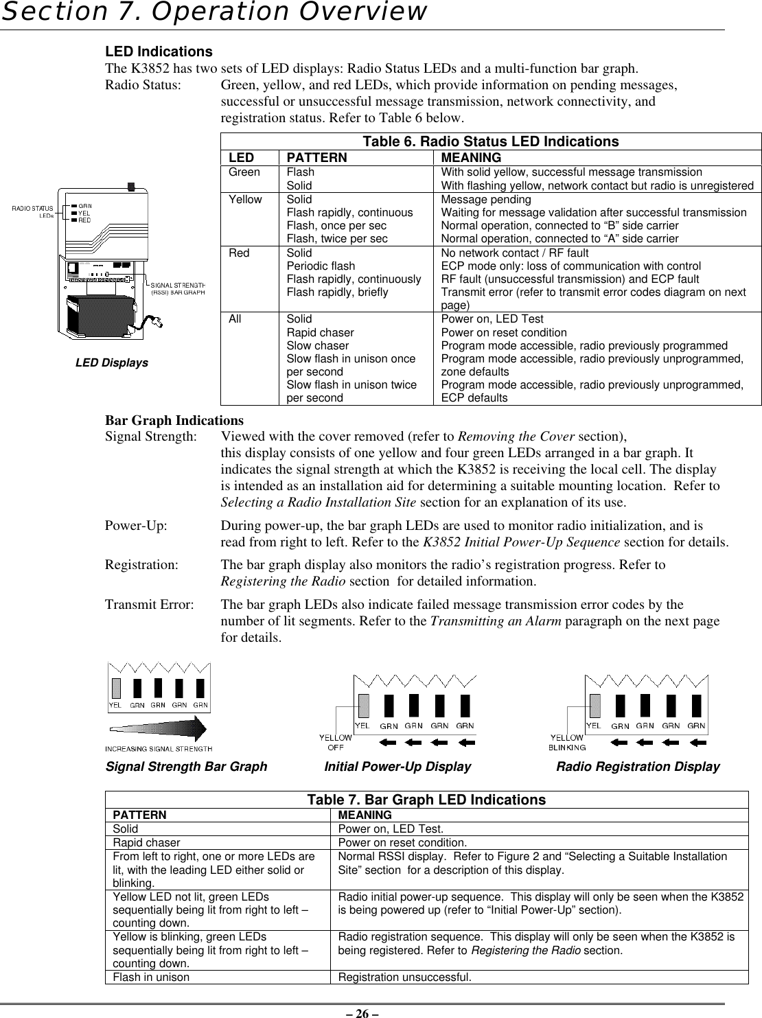
– 26 –Section 7. Operation OverviewLED IndicationsThe K3852 has two sets of LED displays: Radio Status LEDs and a multi-function bar graph.Radio Status: Green, yellow, and red LEDs, which provide information on pending messages,successful or unsuccessful message transmission, network connectivity, andregistration status. Refer to Table 6 below.Table 6. Radio Status LED IndicationsLED PATTERN MEANINGGreen FlashSolid With solid yellow, successful message transmissionWith flashing yellow, network contact but radio is unregisteredYellow SolidFlash rapidly, continuousFlash, once per secFlash, twice per secMessage pendingWaiting for message validation after successful transmissionNormal operation, connected to “B” side carrierNormal operation, connected to “A” side carrierRed SolidPeriodic flashFlash rapidly, continuouslyFlash rapidly, brieflyNo network contact / RF faultECP mode only: loss of communication with controlRF fault (unsuccessful transmission) and ECP faultTransmit error (refer to transmit error codes diagram on nextpage)LED DisplaysAll SolidRapid chaserSlow chaserSlow flash in unison onceper secondSlow flash in unison twiceper secondPower on, LED TestPower on reset conditionProgram mode accessible, radio previously programmedProgram mode accessible, radio previously unprogrammed,zone defaultsProgram mode accessible, radio previously unprogrammed,ECP defaultsBar Graph IndicationsSignal Strength: Viewed with the cover removed (refer to Removing the Cover section),this display consists of one yellow and four green LEDs arranged in a bar graph. Itindicates the signal strength at which the K3852 is receiving the local cell. The displayis intended as an installation aid for determining a suitable mounting location.  Refer toSelecting a Radio Installation Site section for an explanation of its use.Power-Up: During power-up, the bar graph LEDs are used to monitor radio initialization, and isread from right to left. Refer to the K3852 Initial Power-Up Sequence section for details.Registration: The bar graph display also monitors the radio’s registration progress. Refer toRegistering the Radio section  for detailed information.Transmit Error: The bar graph LEDs also indicate failed message transmission error codes by thenumber of lit segments. Refer to the Transmitting an Alarm paragraph on the next pagefor details.Signal Strength Bar Graph Initial Power-Up Display Radio Registration DisplayTable 7. Bar Graph LED IndicationsPATTERN MEANINGSolid Power on, LED Test.Rapid chaser Power on reset condition.From left to right, one or more LEDs arelit, with the leading LED either solid orblinking.Normal RSSI display.  Refer to Figure 2 and “Selecting a Suitable InstallationSite” section  for a description of this display.Yellow LED not lit, green LEDssequentially being lit from right to left –counting down.Radio initial power-up sequence.  This display will only be seen when the K3852is being powered up (refer to “Initial Power-Up” section).Yellow is blinking, green LEDssequentially being lit from right to left –counting down.Radio registration sequence.  This display will only be seen when the K3852 isbeing registered. Refer to Registering the Radio section.Flash in unison Registration unsuccessful.
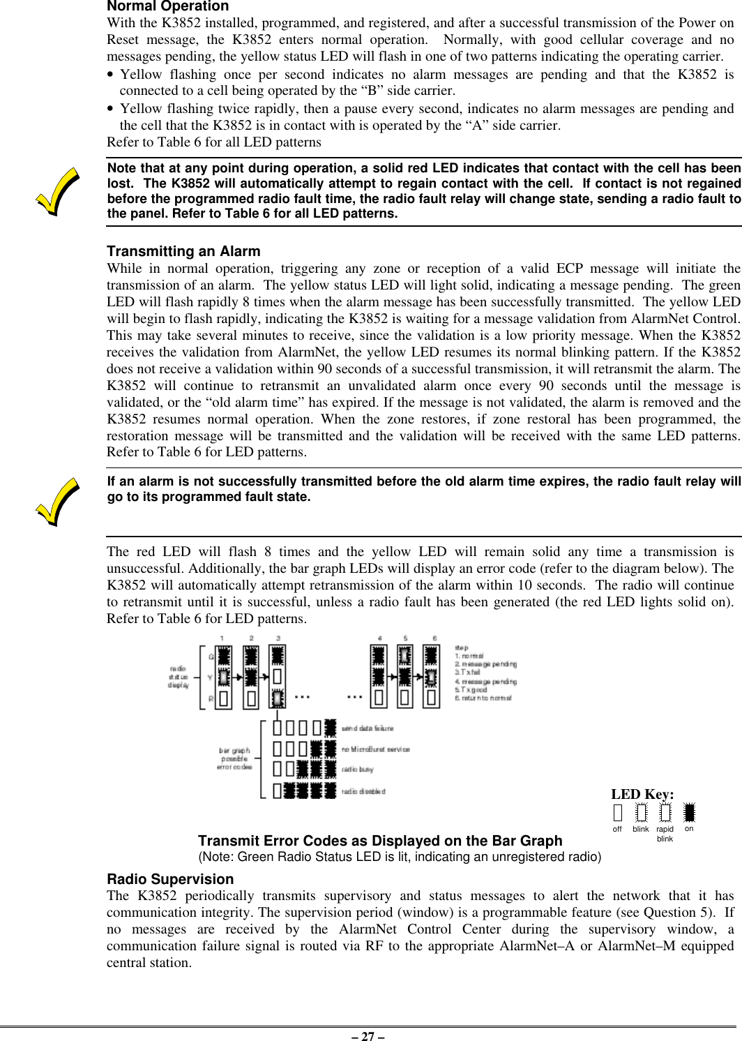
– 27 –Normal OperationWith the K3852 installed, programmed, and registered, and after a successful transmission of the Power onReset message, the K3852 enters normal operation.  Normally, with good cellular coverage and nomessages pending, the yellow status LED will flash in one of two patterns indicating the operating carrier.•Yellow flashing once per second indicates no alarm messages are pending and that the K3852 isconnected to a cell being operated by the “B” side carrier.•Yellow flashing twice rapidly, then a pause every second, indicates no alarm messages are pending andthe cell that the K3852 is in contact with is operated by the “A” side carrier.Refer to Table 6 for all LED patternsNote that at any point during operation, a solid red LED indicates that contact with the cell has beenlost.  The K3852 will automatically attempt to regain contact with the cell.  If contact is not regainedbefore the programmed radio fault time, the radio fault relay will change state, sending a radio fault tothe panel. Refer to Table 6 for all LED patterns.Transmitting an AlarmWhile in normal operation, triggering any zone or reception of a valid ECP message will initiate thetransmission of an alarm.  The yellow status LED will light solid, indicating a message pending.  The greenLED will flash rapidly 8 times when the alarm message has been successfully transmitted.  The yellow LEDwill begin to flash rapidly, indicating the K3852 is waiting for a message validation from AlarmNet Control.This may take several minutes to receive, since the validation is a low priority message. When the K3852receives the validation from AlarmNet, the yellow LED resumes its normal blinking pattern. If the K3852does not receive a validation within 90 seconds of a successful transmission, it will retransmit the alarm. TheK3852 will continue to retransmit an unvalidated alarm once every 90 seconds until the message isvalidated, or the “old alarm time” has expired. If the message is not validated, the alarm is removed and theK3852 resumes normal operation. When the zone restores, if zone restoral has been programmed, therestoration message will be transmitted and the validation will be received with the same LED patterns.Refer to Table 6 for LED patterns.If an alarm is not successfully transmitted before the old alarm time expires, the radio fault relay willgo to its programmed fault state.The red LED will flash 8 times and the yellow LED will remain solid any time a transmission isunsuccessful. Additionally, the bar graph LEDs will display an error code (refer to the diagram below). TheK3852 will automatically attempt retransmission of the alarm within 10 seconds.  The radio will continueto retransmit until it is successful, unless a radio fault has been generated (the red LED lights solid on).Refer to Table 6 for LED patterns.LED Key:Transmit Error Codes as Displayed on the Bar Graph off blink rapidblinkon(Note: Green Radio Status LED is lit, indicating an unregistered radio)Radio SupervisionThe K3852 periodically transmits supervisory and status messages to alert the network that it hascommunication integrity. The supervision period (window) is a programmable feature (see Question 5).  Ifno messages are received by the AlarmNet Control Center during the supervisory window, acommunication failure signal is routed via RF to the appropriate AlarmNet–A or AlarmNet–M equippedcentral station.
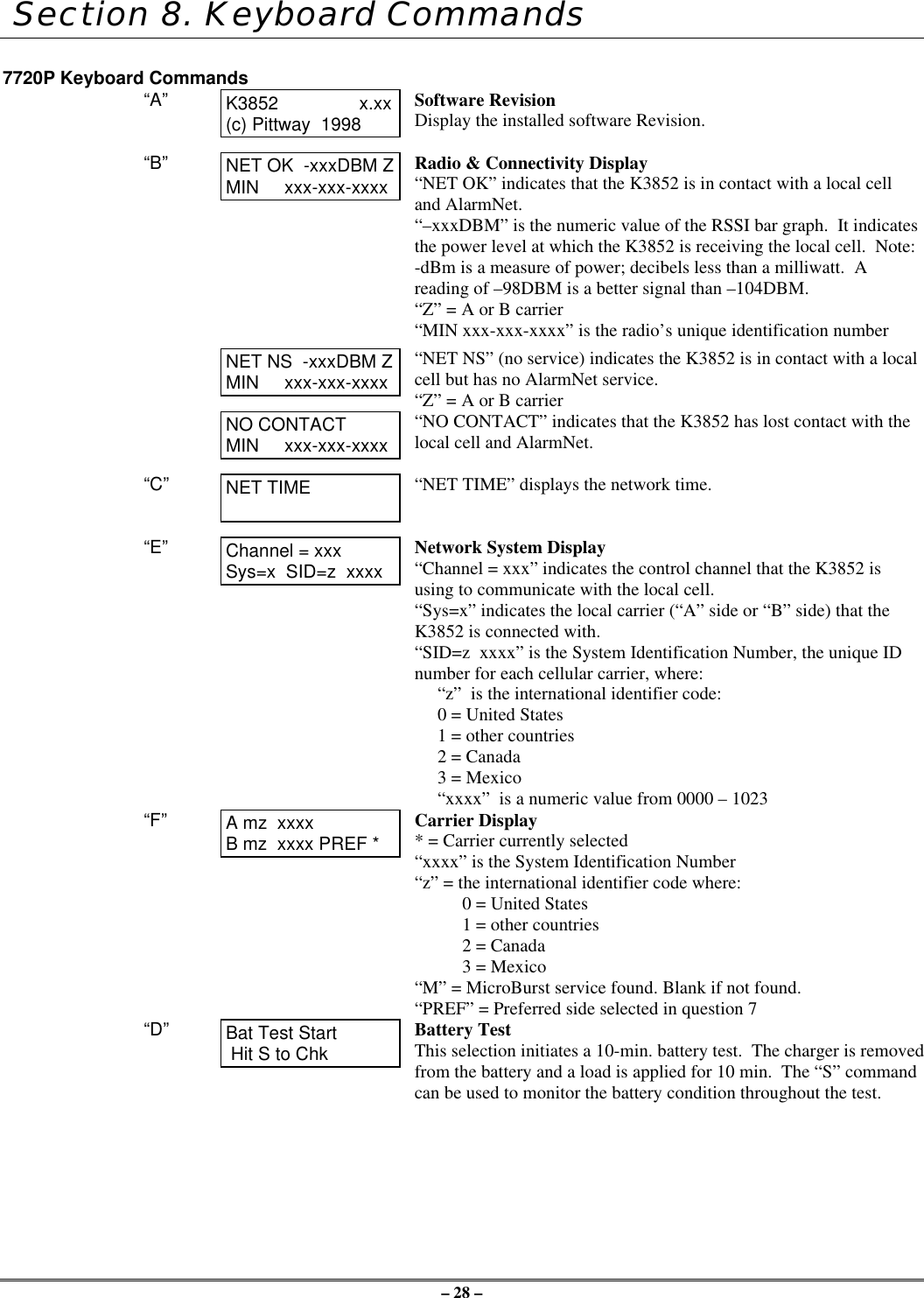
– 28 – Section 8. Keyboard Commands7720P Keyboard Commands“A” K3852                x.xx(c) Pittway  1998Software RevisionDisplay the installed software Revision.“B” NET OK  -xxxDBM ZMIN     xxx-xxx-xxxxRadio & Connectivity Display“NET OK” indicates that the K3852 is in contact with a local celland AlarmNet.“–xxxDBM” is the numeric value of the RSSI bar graph.  It indicatesthe power level at which the K3852 is receiving the local cell.  Note:-dBm is a measure of power; decibels less than a milliwatt.  Areading of –98DBM is a better signal than –104DBM.“Z” = A or B carrier“MIN xxx-xxx-xxxx” is the radio’s unique identification numberNET NS  -xxxDBM ZMIN     xxx-xxx-xxxx“NET NS” (no service) indicates the K3852 is in contact with a localcell but has no AlarmNet service.“Z” = A or B carrierNO CONTACTMIN     xxx-xxx-xxxx“NO CONTACT” indicates that the K3852 has lost contact with thelocal cell and AlarmNet.“C” NET TIME “NET TIME” displays the network time.“E” Channel = xxxSys=x  SID=z  xxxxNetwork System Display“Channel = xxx” indicates the control channel that the K3852 isusing to communicate with the local cell.“Sys=x” indicates the local carrier (“A” side or “B” side) that theK3852 is connected with.“SID=z  xxxx” is the System Identification Number, the unique IDnumber for each cellular carrier, where:“z”  is the international identifier code:0 = United States1 = other countries2 = Canada3 = Mexico“xxxx”  is a numeric value from 0000 – 1023“F” A mz  xxxxB mz  xxxx PREF *Carrier Display* = Carrier currently selected“xxxx” is the System Identification Number“z” = the international identifier code where:0 = United States1 = other countries2 = Canada3 = Mexico“M” = MicroBurst service found. Blank if not found.“PREF” = Preferred side selected in question 7“D” Bat Test Start Hit S to ChkBattery TestThis selection initiates a 10-min. battery test.  The charger is removedfrom the battery and a load is applied for 10 min.  The “S” commandcan be used to monitor the battery condition throughout the test.
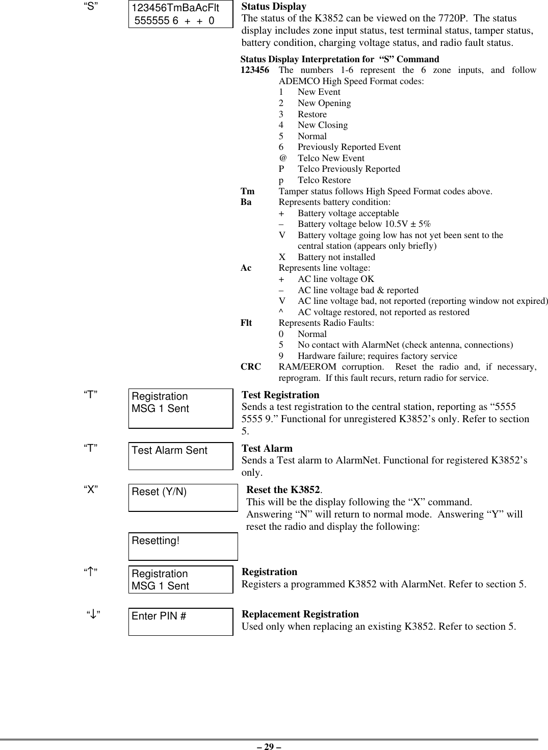
– 29 –“S” 123456TmBaAcFlt 555555 6  +  +  0Status DisplayThe status of the K3852 can be viewed on the 7720P.  The statusdisplay includes zone input status, test terminal status, tamper status,battery condition, charging voltage status, and radio fault status.Status Display Interpretation for  “S” Command123456 The numbers 1-6 represent the 6 zone inputs, and followADEMCO High Speed Format codes:1New Event2New Opening3Restore4New Closing5Normal6Previously Reported Event@Telco New EventPTelco Previously ReportedpTelco RestoreTm Tamper status follows High Speed Format codes above.Ba Represents battery condition:+Battery voltage acceptable–Battery voltage below 10.5V ± 5%V  Battery voltage going low has not yet been sent to the central station (appears only briefly)XBattery not installedAc Represents line voltage:+AC line voltage OK–AC line voltage bad & reportedVAC line voltage bad, not reported (reporting window not expired)^AC voltage restored, not reported as restoredFlt Represents Radio Faults:0Normal5No contact with AlarmNet (check antenna, connections)9Hardware failure; requires factory serviceCRC RAM/EEROM corruption.  Reset the radio and, if necessary,reprogram.  If this fault recurs, return radio for service.“T” RegistrationMSG 1 SentTest RegistrationSends a test registration to the central station, reporting as “55555555 9.” Functional for unregistered K3852’s only. Refer to section5.“T” Test Alarm Sent Test AlarmSends a Test alarm to AlarmNet. Functional for registered K3852’sonly.“X” Reset (Y/N) Reset the K3852.This will be the display following the “X” command.Answering “N” will return to normal mode.  Answering “Y” willreset the radio and display the following:Resetting!“↑↑”RegistrationMSG 1 SentRegistrationRegisters a programmed K3852 with AlarmNet. Refer to section 5. “↓↓”Enter PIN # Replacement RegistrationUsed only when replacing an existing K3852. Refer to section 5.
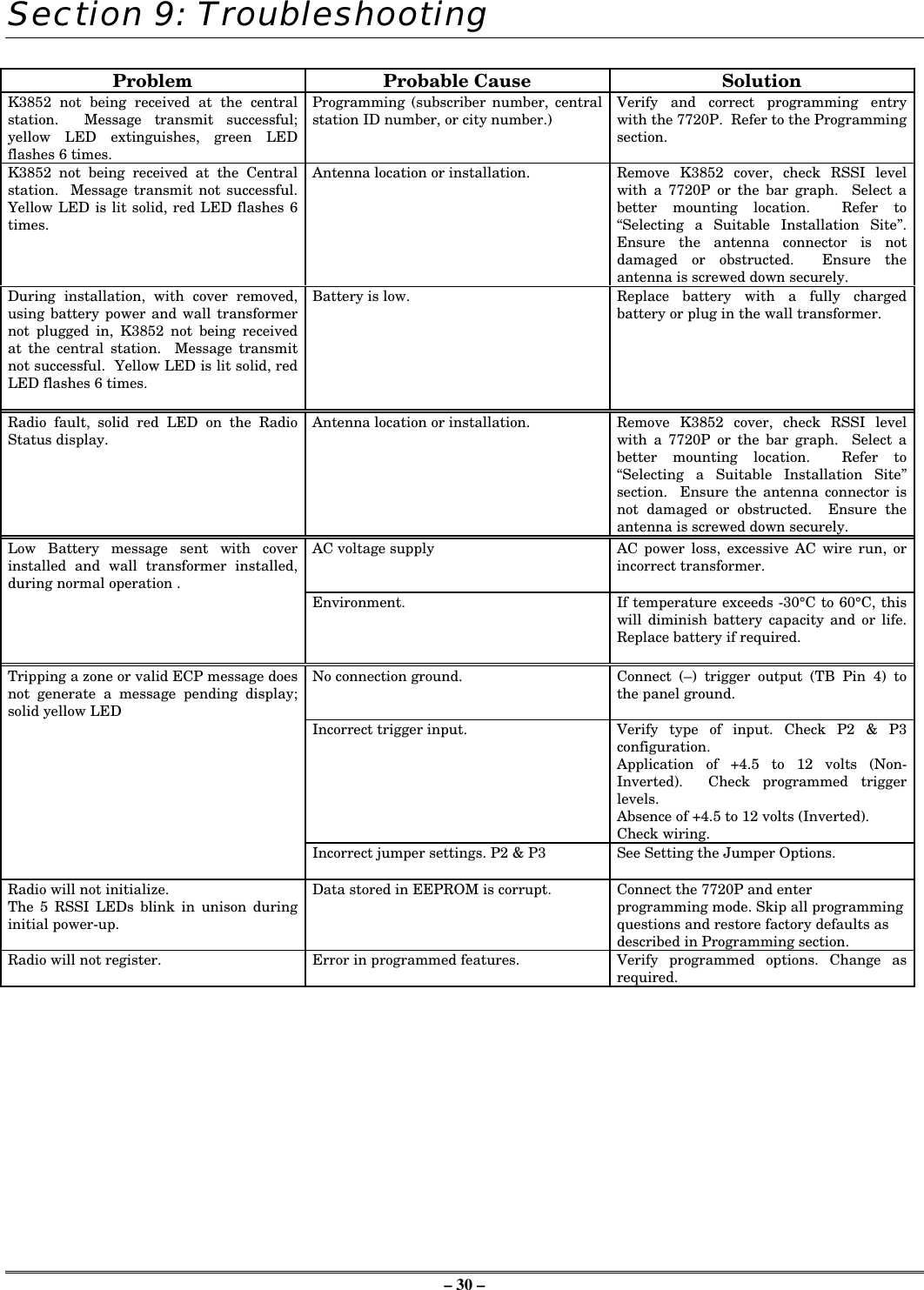
– 30 –Section 9: TroubleshootingProblem Probable Cause SolutionK3852 not being received at the centralstation.  Message transmit successful;yellow LED extinguishes, green LEDflashes 6 times.Programming (subscriber number, centralstation ID number, or city number.) Verify and correct programming entrywith the 7720P.  Refer to the Programmingsection.K3852 not being received at the Centralstation.  Message transmit not successful.Yellow LED is lit solid, red LED flashes 6times.Antenna location or installation. Remove K3852 cover, check RSSI levelwith a 7720P or the bar graph.  Select abetter mounting location.  Refer to“Selecting a Suitable Installation Site”.Ensure the antenna connector is notdamaged or obstructed.  Ensure theantenna is screwed down securely.During installation, with cover removed,using battery power and wall transformernot plugged in, K3852 not being receivedat the central station.  Message transmitnot successful.  Yellow LED is lit solid, redLED flashes 6 times.Battery is low. Replace battery with a fully chargedbattery or plug in the wall transformer.Radio fault, solid red LED on the RadioStatus display. Antenna location or installation. Remove K3852 cover, check RSSI levelwith a 7720P or the bar graph.  Select abetter mounting location.  Refer to“Selecting a Suitable Installation Site”section.  Ensure the antenna connector isnot damaged or obstructed.  Ensure theantenna is screwed down securely.Low Battery message sent with coverinstalled and wall transformer installed,during normal operation .AC voltage supply AC power loss, excessive AC wire run, orincorrect transformer.Environment. If temperature exceeds -30°C to 60°C, thiswill diminish battery capacity and or life.Replace battery if required.Tripping a zone or valid ECP message doesnot generate a message pending display;solid yellow LEDNo connection ground. Connect (–) trigger output (TB Pin 4) tothe panel ground.Incorrect trigger input. Verify type of input. Check P2 & P3configuration.Application of +4.5 to 12 volts (Non-Inverted).  Check programmed triggerlevels.Absence of +4.5 to 12 volts (Inverted).Check wiring.Incorrect jumper settings. P2 & P3 See Setting the Jumper Options.Radio will not initialize.The 5 RSSI LEDs blink in unison duringinitial power-up.Data stored in EEPROM is corrupt. Connect the 7720P and enterprogramming mode. Skip all programmingquestions and restore factory defaults asdescribed in Programming section.Radio will not register. Error in programmed features. Verify programmed options. Change asrequired.
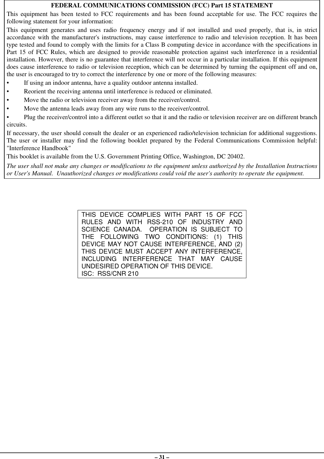
– 31 –FEDERAL COMMUNICATIONS COMMISSION (FCC) Part 15 STATEMENTThis equipment has been tested to FCC requirements and has been found acceptable for use. The FCC requires thefollowing statement for your information:This equipment generates and uses radio frequency energy and if not installed and used properly, that is, in strictaccordance with the manufacturer's instructions, may cause interference to radio and television reception. It has beentype tested and found to comply with the limits for a Class B computing device in accordance with the specifications inPart 15 of FCC Rules, which are designed to provide reasonable protection against such interference in a residentialinstallation. However, there is no guarantee that interference will not occur in a particular installation. If this equipmentdoes cause interference to radio or television reception, which can be determined by turning the equipment off and on,the user is encouraged to try to correct the interference by one or more of the following measures:•If using an indoor antenna, have a quality outdoor antenna installed.•Reorient the receiving antenna until interference is reduced or eliminated.•Move the radio or television receiver away from the receiver/control.•Move the antenna leads away from any wire runs to the receiver/control.•Plug the receiver/control into a different outlet so that it and the radio or television receiver are on different branchcircuits.If necessary, the user should consult the dealer or an experienced radio/television technician for additional suggestions.The user or installer may find the following booklet prepared by the Federal Communications Commission helpful:"Interference Handbook"This booklet is available from the U.S. Government Printing Office, Washington, DC 20402.The user shall not make any changes or modifications to the equipment unless authorized by the Installation Instructionsor User's Manual.  Unauthorized changes or modifications could void the user's authority to operate the equipment.THIS DEVICE COMPLIES WITH PART 15 OF FCCRULES AND WITH RSS-210 OF INDUSTRY ANDSCIENCE CANADA.  OPERATION IS SUBJECT TOTHE FOLLOWING TWO CONDITIONS: (1) THISDEVICE MAY NOT CAUSE INTERFERENCE, AND (2)THIS DEVICE MUST ACCEPT ANY INTERFERENCE,INCLUDING INTERFERENCE THAT MAY CAUSEUNDESIRED OPERATION OF THIS DEVICE.ISC:  RSS/CNR 210
– 32 –UL RequirementsBelow is a list of UL requirements that must be met for UL installations.NOTE: The K3852 is not UL Listed for fire alarm service. For fire, the K3852F can be used as the backup dialer. K3852F isnot approved for use as the primary fire dialer.1. There are no UL Listed siren drivers available for commercial burglar alarm use.2. When the K3852 is set for Zone Mode operation on a UL commercial burglar alarm installation, all interconnectingwiring between the control unit and the K3852 must be no more than 3 feet in length and contained within the sameroom. All interconnecting wiring must be installed in rigid conduit or EMT (where exposed on interior walls) or inflexible metal tubing if run in the walls or ceiling.3. The wiring method shown in Figure 11 (page 23) is required on UL installations. The Low Current Mode may not beused on UL installations.4. For all modes of operation, commercial burglar alarm installations must be in accordance with the National ElectricalCode and UL681, Installation and Classification of Burglar and Hold-Up Alarm Systems.5. For all modes of operation, residential burglar alarm installations must be in accordance with the National ElectricalCode and UL1641, Installation and Classification of Residential Burglar Alarm Systems.6. For Zone Mode operation, the K3852 must be connected to either dry contacts or voltage trigger outputs of a Listedcompatible control unit.7. For ECP Mode, the K3852 must be connected to a Listed compatible ECP capable control unit.8. The antenna (and thereby the K3852) may be mounted remotely from the control panel when ECP mode is used.9. The K3852 must be programmed as follows:a. The K3852 must be registered as described in the Installation Instructions.b. Zones must be programmed “No” for “Pulsed” and “00” for “Delay” (Questions 9-14)c. Enable restoral signals (Questions 21-26).d. At least one zone must be set to provide opening and closing signals (Question 28).e. At least one zone must be programmed to provide Telco Channel monitoring (Question 29).f. Either zone 7 or 8 must be enabled as the Tamper zone (Question 30).g. The Old Alarm Time must be set to 10 minutes (Question 31)h. AC Loss Report must be enabled (Question 32).i. Bat Present must be enabled (Question 33).j. Fault Relay On must be enabled (Question 34).k. 24 Hour Supervision must be enabled (Question 5).
– 33 –– NOTES –
– 34 –SpecificationsDimensions: .............................5” x 9.25” x 1.625” without antennaPower: .....................................ADEMCO 1361 Transformer (16.5VAC, 40VA)Backup Battery ........................ADEMCO 7720BTAC Current drain:  ...................Normal operation: 330mA AC(2.0A AC peak during transmission)Radio fault output: ...................Form A contacts rated for 0.5A, 125VACInput triggering levels:.............Zones 1 and 2: selectable GND or 4.5 to 14.2 volts into 10k-ohmsZones 3-6:  4.5 to 12 volts into 10k-ohmsRF power output: .....................600mWFrequency band: ......................833-835MHz Transmit878-880MHz ReceiveChannel separation:..................30kHzReceiver sensitivity:.................-115dBmOperating temp:  ......................-30 to +60 deg. CelsiusStorage temp:  ..........................-40 to +70 deg. CelsiusHumidity: ................................0-90% relative humidity, noncondensingAltitude:  ..................................to 10,000 ft. operating, to 40,000 ft. storageAntenna: ..................................ADEMCO K3209 Cellular Antenna, included
– 35 –Summary of ConnectionsK3852 SUMMARY OF CONNECTIONS DIAGRAM
ADEMCO LIMITED WARRANTYAlarm Device Manufacturing Company, a Division of Pittway Corporation, and its divisions, subsidiaries and affiliates ("Seller"), 165Eileen Way, Syosset, New York 11791, warrants its products to be in conformance with its own plans and specifications and to be freefrom defects in materials and workmanship under normal use and service for 24 months from the date stamp control on the product or, forproducts not having an Ademco date stamp, for 12 months from date of original purchase unless the installation instructions or catalog setsforth a shorter period, in which case the shorter period shall apply. Seller's obligation shall be limited to repairing or replacing, at its option,free of charge for materials or labor, any product which is proved not in compliance with Seller's specifications or proves defective in ma-terials or workmanship under normal use and service. Seller shall have no obligation under this Limited Warranty or otherwise if theproduct is altered or improperly repaired or serviced by anyone other than Ademco factory service. For warranty service, return producttransportation prepaid, to Ademco Factory Service, 165 Eileen Way, Syosset, New York 11791.THERE ARE NO WARRANTIES, EXPRESS OR IMPLIED, OF MERCHANTABILITY, OR FITNESS FOR A PARTICULARPURPOSE OR OTHERWISE, WHICH EXTEND BEYOND THE DESCRIPTION ON THE FACE HEREOF. IN NO CASE SHALLSELLER BE LIABLE TO ANYONE FOR ANY CONSEQUENTIAL OR INCIDENTAL DAMAGES FOR BREACH OF THIS OR ANYOTHER WARRANTY, EXPRESS OR IMPLIED, OR UPON ANY OTHER BASIS OF LIABILITY WHATSOEVER, EVEN IF THELOSS OR DAMAGE IS CAUSED BY THE SELLER'S OWN NEGLIGENCE OR FAULT.Seller does not represent that the products it sells may not be compromised or circumvented; that the products will prevent any personalinjury or property loss by burglary, robbery, fire or otherwise; or that the products will in all cases provide adequate warning or protection.Customer understands that a properly installed and maintained alarm may only reduce the risk of a burglary, robbery, fire or other eventsoccurring without providing an alarm, but it is not insurance or a guarantee that such will not occur or that there will be no personal injuryor property loss as a result. CONSEQUENTLY, SELLER SHALL HAVE NO LIABILITY FOR ANY PERSONAL INJURY,PROPERTY DAMAGE OR OTHER LOSS BASED ON A CLAIM THE PRODUCT FAILED TO GIVE WARNING. HOWEVER, IFSELLER IS HELD LIABLE, WHETHER DIRECTLY OR INDIRECTLY, FOR ANY LOSS OR DAMAGE ARISING UNDER THISLIMITED WARRANTY OR OTHERWISE, REGARDLESS OF CAUSE OR ORIGIN, SELLER'S MAXIMUM LIABILITY SHALLNOT IN ANY CASE EXCEED THE PURCHASE PRICE OF THE PRODUCT, WHICH SHALL BE THE COMPLETE AND EX-CLUSIVE REMEDY AGAINST SELLER. This warranty replaces any previous warranties and is the only warranty made by Seller on thisproduct. No increase or alteration, written or verbal, of the obligations of this Limited Warranty is authorized.165 Eileen Way, Syosset, NY 11791Copyright © 1998  PITTWAY CORPORATIONÊK3204V16ŠK3204V1  2/99

Navigation menu