Ademco K3852 Cellular Control Channel Transceiver User Manual K3852InstallationAnd SetupGuide
Honeywell International Inc. Cellular Control Channel Transceiver K3852InstallationAnd SetupGuide
Ademco >
Contents
- 1. Users Manual
- 2. Revised Section of Installation Manual
Users Manual
K3852K3852
CellularCellular
Control Channel TransceiverControl Channel Transceiver
Installation and Setup GuideInstallation and Setup Guide
NOW
PRO*
ENABLED!
*P
ROGRAMMERLESS
R
EGISTRATION
O
PTION
K3852V1 2/99

– 2 –
Table of Contents
List of Terms...................................................................................................................................................2
Section 1. General Information .......................................................................................................................3
Introduction.......................................................................................................................................3
System Features ................................................................................................................................3
Section 2. Quick Start/Programming Guide....................................................................................................4
Section 3. Installation and Setup .....................................................................................................................6
Removing the Lower Cover..............................................................................................................6
Initial Power-Up Sequence ...............................................................................................................7
Selecting a Radio Installation Site ....................................................................................................8
Testing the Installation......................................................................................................................9
Section 4. Programming the K3852 ..............................................................................................................10
Using a 7720P Programming Tool..................................................................................................10
Subscriber Information....................................................................................................................11
Pulse/Delay Zone Selection ............................................................................................................12
Inverted Zone Selection ..................................................................................................................13
Restoral Reporting Zone Selection .................................................................................................14
Open/Close, Telco, Tamper Zone Selection ...................................................................................15
System Options ...............................................................................................................................15
Redundant Central Station Reporting .............................................................................................16
Exiting Program Mode, Setting Defaults and Assigning Passwords...............................................17
Section 5. Registration ..................................................................................................................................18
Section 6. Mounting and Wiring ...................................................................................................................21
Section 7. Operation Overview .....................................................................................................................26
Section 8. Keyboard Commands ...................................................................................................................28
Section 9. Troubleshooting............................................................................................................................30
UL Requirements ..........................................................................................................................................32
Specifications ................................................................................................................................................34
Summary of Connections Diagram ...............................................................................................................35
List of Terms
AMPS: Acronym for Advanced Mobile Phone System, which is the existing analog mobile phone
system used for cellular communication in North America.
A Side / B-Side: The FCC has divided the spectrum allocated to cellular communication between two
carriers in each geographic location: A and B. The “B” side is operated by the local
telephone company (known as wireline), while the “A” side is run by a competitor
(known as non-wireline).
Cell: The equipment, including antennas, RF transmitters, RF receivers, that is used to
establish and route communications between a mobile cellular radio and its intended end
point.
Control Channel: Any one of several dedicated RF channels that are used by a cellular radio to register its
MIN with a local cell and to periodically check in with that cell. The control channel is
also used by the radio to “dial” a phone number through the cell. Additionally, control
channels are used by the cell to “ring” a mobile cellular radio.
MIN: Acronym for Mobile Identification Number, which is a cellular radio’s unique, 10-digit
“phone number.”
SS7: Acronym for Signaling System Seven, which is the network that is used by all telephone
companies for dialing and establishing all cellular and land-line phone calls.
Voice Channel: Any one of many dedicated RF channels used for transmitting and receiving audio data
between a mobile phone and a cell. (Not used with the K3852.)

– 3 –
Section 1: General Information
Introduction The K3852 is the subscriber end of the AlarmNet C reporting system. It is comparable to a digital
communicator, but instead of transmitting signals over the telephone lines, it transmits radio signals to the
central monitoring station using the control channel of the AMPS cellular phone network. This allows
faster and more secure reporting and greater coverage.
The K3852 is compatible with existing installations using ADEMCO equipment or other control panels. It
can be used in conjunction with digital communicators on the same system to provide redundant reporting.
The K3852 Transceiver uses the control channel of the Advanced Mobile Phone System (AMPS) cellular
network to report subscriber alarms and system status messages. It operates on either the “A” or “B” side
of the cellular network without using a voice channel. Because alarms are transmitted only on the control
channel, a true “phone call” is never placed. This eliminates delays due to busy or saturated cells where no
voice channels are available.
The K3852 is compliant with the MicroBurst standard for packet-based control channel cellular
communication. Alarm and status packets are transmitted from the subscriber to a local cell where they are
identified and then routed using SS7 to the AlarmNet Control Center. The AlarmNet Control Center then
logs the alarm and routes it via RF to the appropriate AlarmNet-A or AlarmNet-M equipped central station.
System Features
Hardware Features
• Up to 6 input zones (when ECP is not used) that can be triggered by either applying or removing a
voltage.
• Zones 1 and 2 are configurable to trigger on the application of a voltage or ground.
• Zones 5 and 6 are configurable as voltage-tripped zones or as ECP IN / ECP OUT, respectively (the
installer must choose either zone inputs or ECP communication, not both).
• Radio fault relay Form A contacts, programmable.
• Auxiliary, general purpose relay, Form A contacts, controllable across the radio link.
• Trigger voltage for use with dry contact relays.
LED Indications
• Received Signal Strength Indication (RSSI), displayed on a 5-position bar graph.
• Three radio status LEDS to indicate message status and radio status.
Antenna
• ADEMCO cellular antenna included (part number K3209).
Power
• Wall-mounted 16.5VAC / 40VA transformer ADEMCO PN: 1361 (1361CN for Canadian installations).
• Optional battery backup adds over 4 hours of additional system life during AC loss. ADEMCO PN:
7720BT
Programmable Features
• Subscriber, city and central station ID •Tamper zone
• Carrier selection •Old alarm time reporting period
• Supervision messaging period •AC loss reporting
• Time zone •Battery backup with optional battery
• Steady state or pulsed zones with delays •Radio fault relay
• Inverted zone trigger levels •Radio fault time
• Zone restoration messaging •Secondary CS reporting
• Open/Close reporting •Password assignment
• Telco fault zone
– 4 –
Section 2: Quick Start/Programming Guide
1. Unpack and initialize the radio.
a. Unpack the K3852 and install the antenna.
b. Remove the unit’s lower cover (refer to Removing the Lower Cover section).
c. Connect a fully charged battery (Ademco 7720BT) or a 40VA transformer (Ademco 1361 or 1361CN).
d. Monitor the initial power-up LED sequence (refer to the Initial Power-Up Sequence section). This can
take several minutes.
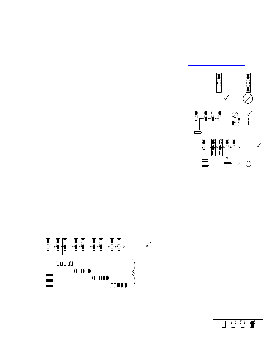
2. Find coverage and select a site.
If this is the first K3852 to be installed in a given area, please verify that there is coverage in that ZIP code
by either checking the coverage selection at the AlarmNet web site www.ademco.com/alarmnet, or by
calling 1-800-222-6525 and asking our technical assistance group.
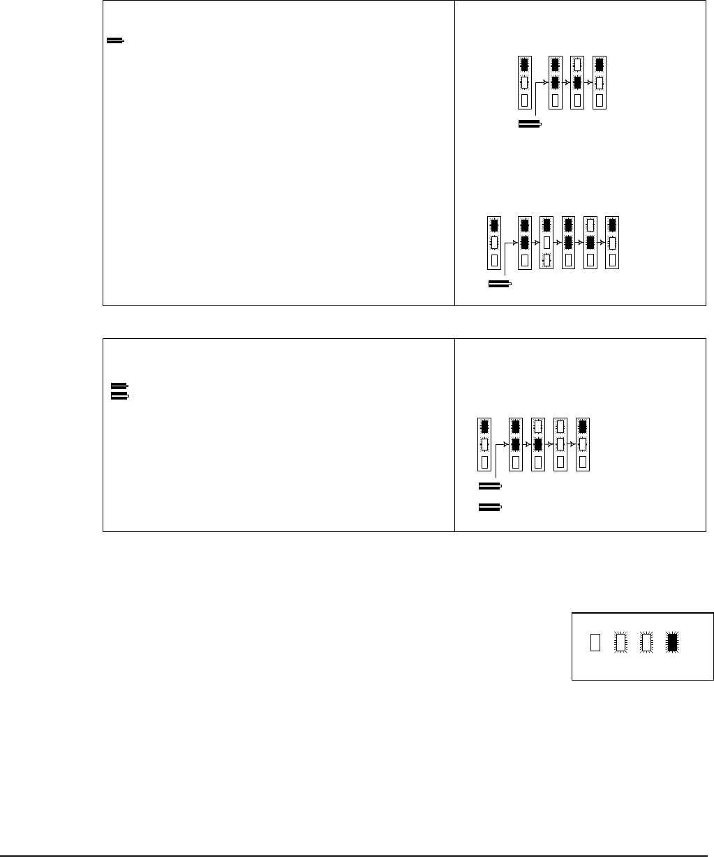
a. Verify MicroBurst coverage using the radio status LEDs as shown at
right, or use the “B” command on the 7720P Programming Tool.
b. Select an installation site by observing the signal strength (RSSI) bar
graph or use the “B” command on the 7720P Programming Tool (refer
to the Selecting a Radio Installation Site section for detailed procedure).
3. Test the site.
a. Test the RF link between the K3852 and the local cell with a single
click test message (refer to the Testing section for details).
b. Test communication with the AlarmNet C network by double
clicking the tamper/test switch and receiving message validation. If
desired, you can cancel validation by clicking the tamper switch
once.
4. Program the radio.
a. Connect the 7720P Programming Tool, reset the radio by cycling the power off then on; press [Enter]
during the initial power-up sequence to enter Programming mode.
b. Program the K3852 as described in the Programming section. Refer to the programming defaults on the
next page.
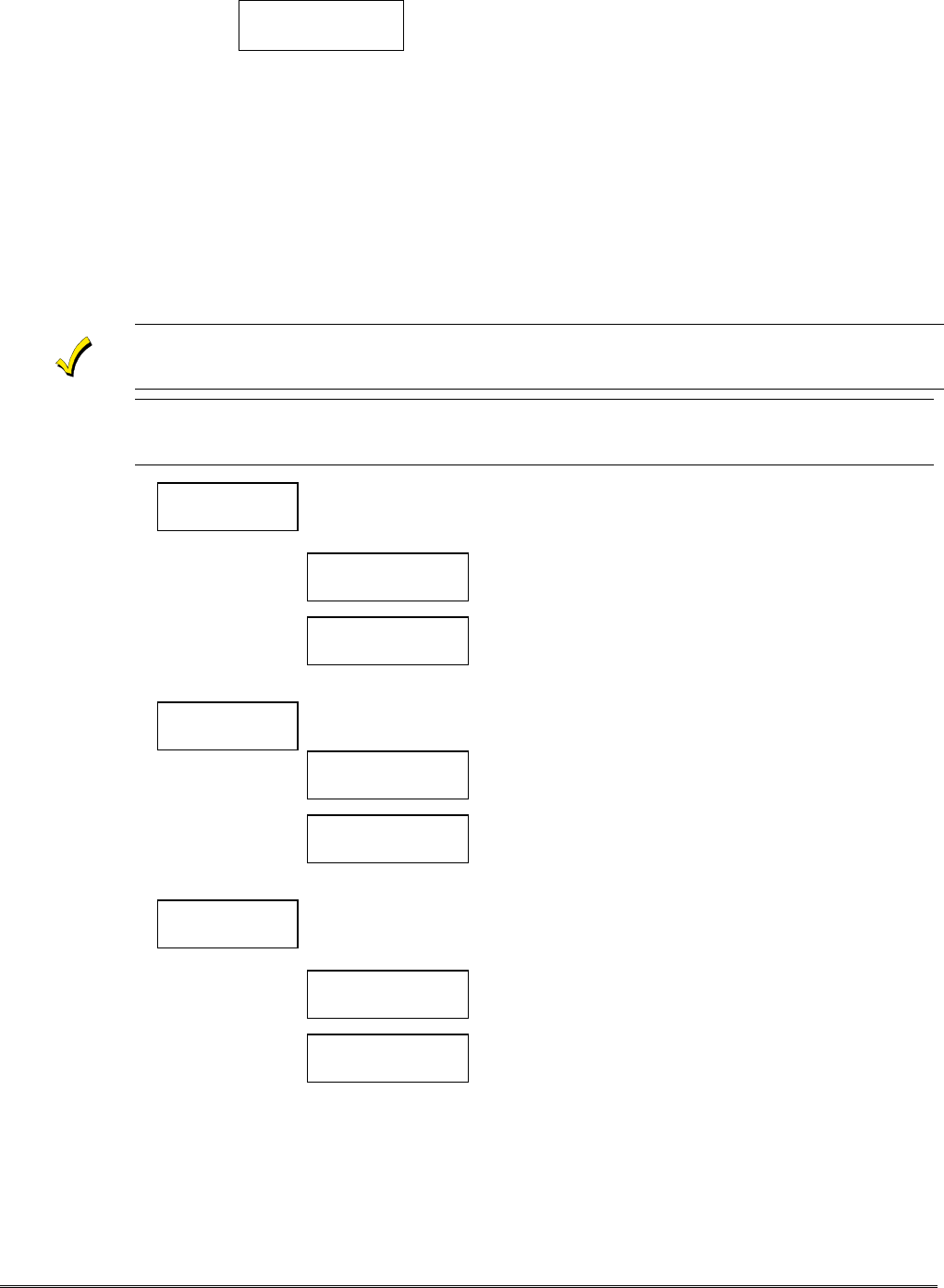
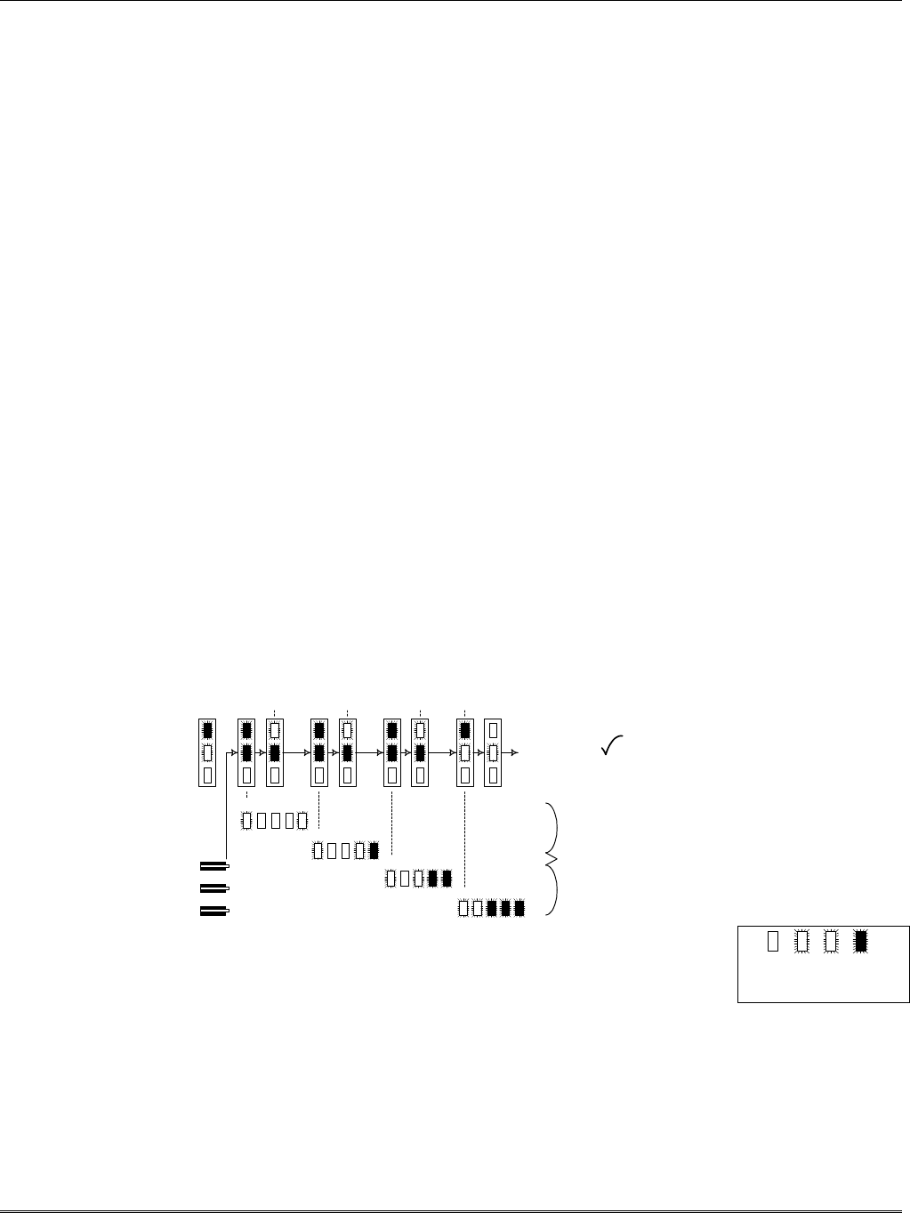
5. Register the radio.
a. Send test registration with the 7720P “T” command to verify account and routing.
b. Register the K3852 with AlarmNet by triple clicking the tamper switch and observing the LED displays
as shown below, or by pressing the [↑] key on the 7720P.
6. Complete the installation.
a. Mount the radio (refer to the Mounting section).
b. Wire to the Control (refer to the Wiring section) and test all signals.
c. Test the installation (refer to the Testing section)
off blink rapid
blink
on
LED Key
G
Y
R
MicroBurst MicroBurst
G
Y
R
"click"
1.5 bars min
RSSI RSSI
YG G G G
G
Y
R
G
Y
R
"click"
"click"
"click"
VALIDATION
VALIDATION
"click"
"click"
"click"
REGISTRATION
G
Y
R
registration
progress
YG G G G
YG G G G
YG G G G
YG G G G
MSG 1
SENT MSG 2
SENT MSG 3
SENT WAIT
ACK

– 5 –
Quick Start/Programming Guide
K3852 Programming Defaults for Zone Mode
* Options 2, 3 and 4 must be programmed to complete Quick Start.
Programming Option Standard
Default Value Actual
Entry 7720P Keyboard Commands
1ECP Radio (Y/N) NASoftware revision
2ID Number * xxxx BRadio and connectivity display (network OK, no service, no
3City Number * xx contact, signal strength, A or B carrier, MIN)
4CS ID * xx CNetwork time display
5Supervision 24 hours DBattery test (starts 10 minute battery test)
6Time Zone Eastern ENetwork system display (channel, local carrier, SID)
7Carrier Select Auto FCarrier display (A or B carrier, MicroBurst found, preferred
8Device Address (ECP only) xx side indication)
9a Pulse Z1 (Y/N) NSStatus display
9b Z1 Delay (00-127) 0TTest signal/Test registration when unregistered
10a Pulse Z2 (Y/N) NXReset
10b Z2 Delay (00-127) 0↑↑ Register radio (must be programmed)
11a Pulse Z3 (Y/N) N↓↓ Replacement radio (must have PIN)
11b Z3 Delay (00-127) 0
12a Pulse Z4 (Y/N) N
12b Z4 Delay (00-127) 0
13a Pulse Z5 (Y/N) N
13b Z5 Delay (00-127) 0
14a Pulse Z6 (Y/N) N
14b Z6Delay (00-127) 0
15 Invert Z1 (Y/N) N
16 Invert Z2 (Y/N) N
17 Invert Z3 (Y/N) N
18 Invert Z4 (Y/N) N
19 Invert Z5 (Y/N) N
20 Invert Z6 (Y/N) N
21 Restore Z1 (Y/N) N
22 Restore Z2 (Y/N) N
23 Restore Z3 (Y/N) N
24 Restore Z4 (Y/N) N
25 Restore Z5 (Y/N) N
26 Restore Z6 (Y/N) N
27 Arm/Disarm Z6 (Y/N) N
27a Enable Z1 on arm (Y/N) N
27b Enable Z2 on arm (Y/N) N
27c Enable Z3 on arm (Y/N) N
27d Enable Z4 on arm (Y/N) N
27e Enable Z5 on arm (Y/N) N
28 Open/Close Zone 0
29 Telco Channel 0
30 Tamper Zone 0
31 Old Alarm Time 10 minutes
32 AC Loss Report Y
33 Battery Present (Y/N) Y
34 Fault Relay On (Y/N) N
35 Fault Time (minutes) 5
36 2nd CS (Y/N) N
37 2CS Z1 (Y/N) N
38 2CS Z2 (Y/N) N
39 2CS Z3 (Y/N) N
40 2CS Z4 (Y/N) N
41 2CS Z5 (Y/N) N
42 2CS Z6 (Y/N) N
43 2CS Tamp (/N) N
44 2CS Sys Rpt (Y/N) N
45 2nd ID # xxxx
46 2nd City xx
47 2nd CS ID xx
48 Review? N
49 Enter Password? (Y/N) N
– 6 –
Section 3: Installation and Setup
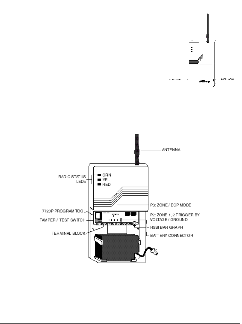
Removing the Lower Cover
During normal operation, the lower cover of the K3852 should
remain in place.
To remove the cover, gently press in on either of the two
locking tabs and lift the cover.
Removing the cover will trigger the following two events:
1. A tamper zone alarm will be transmitted.
2. The RSSI bar graph, which is intended to be used as an
installation tool and troubleshooting aid, will become
active.
!Do not attempt to remove the upper cover. There are no user serviceable components
beneath this cover.
Refer to the following diagram to identify the components of the K3852.
Figure 1. K3852 with Cover Removed for Component Identification
– 7 –
K3852 Initial Power-Up Sequence
Before connecting power, check that the following have been completed:
q 16.5VAC / 40VA transformer connected to terminal block positions 1 & 2
q P2 in the correct position for zone 1 & 2 trigger levels (zone mode only)
q P3 in the correct position for zone or ECP operation
q Antenna installed
Apply power by plugging in the 16.5VAC / 40VA transformer. If using the optional battery, plug it into
the battery jack. Initially, all K3852 programming options are set to the factory default settings.
Upon applying power, the K3852 enters the power-on reset mode, indicated by all 8 LEDs being solidly lit
for approximately 5 seconds followed by the RSSI bar graph green LEDs lighting in a “chaser” sequence
from left to right. After this power-up sequence, the Radio Status LEDs display solid green, blinking
yellow, and solid red.
This indicates the K3852 is functioning but not yet initialized. The K3852 then begins its initialization
sequence. During this process, the K3852 is verifying its Mobile Identification Number (MIN) and
checking for MicroBurst service on both the “A” and “B” side carriers. This initialization is displayed on
the RSSI bar graph as follows (refer to Table 1): The yellow LED will remain unlit and the green LED at
the extreme right of the display will begin to blink. This green LED then lights solid (after a short period
of time), and the next green LED to the left begins to blink. When this LED lights solid, the next green
LED begins to blink, and so on, until all 4 green LEDs are lit solid. This countdown event may take up to 3
minutes to complete.
Once this sequence has been completed, the RSSI display begins to function as a signal strength indicator
as described in Selecting a Radio Installation Site section. The radio is now in normal, unprogrammed and
unregistered operation. If radio setup and self-test fails, LED 5 will blink continuously and no further
progress will be made. If MicroBurst coverage is not found on either the A or the B side, the K3852 will
repeat steps 2 and 3. These steps will be repeated until MicroBurst is found.
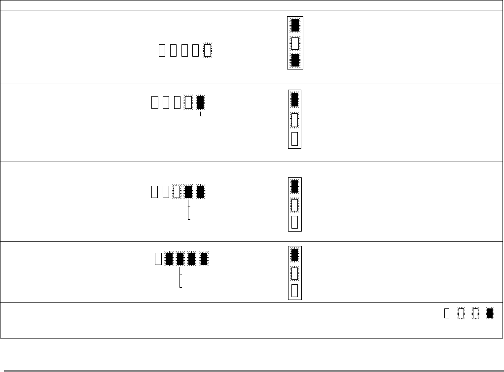
Table 1. K3852 Initial Power-Up Bar Graph and Radio Status LED Sequence
Active Function Bar Graph Display Radio Status Display
1) LED 5 blinking: K3852 performing
radio setup and self-test.
Time to complete: less than 1 minute.
NOTE: If the K3852 fails the self-test,
the initial powerup will not progress
beyond this point.
Green on: un-registered
Yellow blinking: waiting
Red on: no MicroBurst coverage
2) LED 4 blinking: K3852 searching for
MicroBurst coverage from the B-side
carrier.
Time to complete: 1 – 3 minutes
5 on: radio set-up ok.
Green on: un-registered radio
Green blinking: service request message successful, B-side
Green off: previously registered radio
Yellow on: request for service message pending, B-side
Yellow blinking: B-side (once per second)
Red on: MicroBurst coverage not yet found, B-side
Red blinking: service request message un-successful, B-side
Red off: MicroBurst coverage found, B-side
3) LED 3 blinking: K3852 searching for
MicroBurst coverage from the A-side
carrier.
Time to complete: 1 – 3 minutes
Green on: un-registered radio
Green blinking: service request successful, A-side
Green off: previously registered radio
Yellow on: request for service pending, A-side
Yellow blinking: A-side (twice per second)
Red on: MicroBurst coverage not yet found, A-side
Red blinking: service request message un-successful, A-side
Red off: MicroBurst coverage found, A-side
4) LED 2 on: K3852 initial powerup
complete.
Time to complete: 10 seconds
Green on: un-registered radio
Green off: previously registered radio
Yellow blinking: A-side or B-side blink indication
Red on: no MicroBurst coverage
Red off: MicroBurst coverage, carrier indicated by Yellow LED
LED Key: off blink rapid
blink
on
1 2 3 4 5
Y G G G G
4 on: B-side MicroBurst OK
or
4 off: B-side MicroBurst fail.
3 on: A-side MicroBurst OK
or
3 off: A-side MicroBurst fail.
G
Y
R
G
Y
R
G
Y
R
G
Y
R
– 8 –
Selecting a Radio Installation Site
The K3852 is designed to be mounted on a vertical surface (wall), with the included antenna pointing up.
When selecting mounting a site, maintain distances from various types of electrical equipment as listed in
Table 2. Additionally, observe the maximum wire run lengths (see Table 4).
The K3852 is intended for indoor installation only. Mounting outdoors will cause system failure and
may present a shock hazard.
1. Remove the cover and install a fully charged battery. If a fully charged battery is not available, you can
connect a 16.5VAC / 40VA transformer.
During battery operation, removal of the lower cover will significantly reduce the life of the charge on
the battery. To get the maximum backup battery life in the event of an AC loss, the lower cover must
be replaced when the installation is complete. (Note that the signal strength bar graph located below
this cover is only needed during installation.)
2. Select a likely location by monitoring the signal strength bar graph. Refer to the Using an Unregistered
K3852 as an Installation Tool paragraph below. A strong signal lights more LEDs than a weak signal.
3. Find a location where the signal level is consistently better than 1-½ bars or –101dBm as measured
with the 7720P. The K3852 can function properly with the signal strength level as low as one-half bar
(yellow blinking), but this may be an indication of marginal coverage.
Notes:
1. Optimum RF performance can usually be found at the highest point within a building, with the fewest
number of walls between the radio and the outside of the premises.
2. Avoid mounting the antenna near other electronic devices. Table 2 provides minimum distances.
Highest RF energy is in the direct, horizontal line of the antenna. Therefore, vertical separation
(moving electronic devices either higher or lower on the wall) provides a higher level of isolation from
the radio.
Table 2. Minimum Distances From Electrical Equipment
Equipment Distance
PIR 10 ft.
FM radio or TV ant. 25 ft.
Other devices 10 ft. minimum
Using an Unregistered K3852 as an Installation Tool
An unregistered K3852 will display signal strength once the initial
power-on sequence is complete.
Use the guide on the right when selecting an installation site.
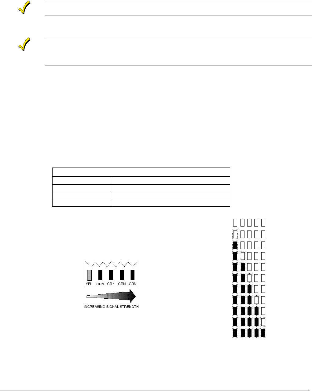
Select an installation site where the RSSI is between 1.5 – 5 bars.
Signal Strength Bar Graph Displays
0.0 no signal
0.5
1.0
2.0
2.5
3.0
3.5
4.0
4.5
5.0 max signal
1.5 min
installation level
– 9 –
Testing the Installation
Using an Unregistered K3852 to Test the Installation
An unregistered K3852 can send three types of test messages: unvalidated, validated, and test registration.
Refer to the table below.
Unvalidated Test Message
Use this to test the path from the K3852 to the cell.
SINGLE click the tamper switch to send a test message
to the local cell. The RSSI bar graph displays how well the
K3852 is receiving this cell. Read the RSSI display from
left to right: If the yellow and the next two green LEDs are
illuminated, the display is read as “three bars.” If the
yellow and the next two green LEDs are lit solid with the
following green LED flashing, the display is read as “three
and a half bars.” This is a stronger received signal than the
previous example. Refer to the Full Scale RSSI Display
diagram on the previous page.
Radio status LEDs for a good test
message transmission to local cell:
Radio status LEDs for a failed test
message transmission and a good
retransmission to local cell:
Validated Test Message
Use this to test the path from the K3852 to AlarmNet and
back to the K3852.
DOUBLE click the tamper switch to send a test
message to AlarmNet with a validation request. The yellow
radio status LED blinks rapidly while waiting for
validation. Validation is a low priority receipt from
AlarmNet to the K3852 and may take several minutes to
receive. If a message is not validated by AlarmNet within
90 seconds, the K3852 will retransmit the test message and
wait for validation.
Radio status LEDs for a good test
message transmission to AlarmNet and
validation:
NOTE: When a good test message is sent from the K3852, it can be assumed with a high degree certainty
that it reached AlarmNet without waiting for validation
To cancel any test message, SINGLE click the tamper switch.
LED Key:
off blink rapid
blink
on
Test Registration
Use this to test the path from the K3852 to AlarmNet, then to the central station, and back to the K3852.
This confirms the radio’s programming and routing across the AlarmNet network without actually
registering it.
NOTE: Quick Start Programming Options 2, 3, and 4 must be programmed to use this feature.
Use the “T” command on the 7720P to initiate test registration. Refer to section 5 for a detailed description
of this feature
"click"
G
Y
R
1 2 3 4
step
1. normal
2. message pending
3. Tx good
4. return to normal
"click"
G
Y
R
234
step
1. normal
2. message pending
3. Tx fail
4. message pending
5. Tx good
6. return to normal
1 5 6
"click"
G
Y
R
1 2 3 4
step
1. normal
2. message pending
3. Tx good
4. waiting for validation
5. return to normal
"click"
5

– 10 –
Section 4: Programming the K3852
There are 3 methods of programming the K3852: (1) Using a 7720P Programming Tool; (2) using an ECP
capable control panel that supports long range radio programming,; (3) using the Programmerless
Registration Option (PRO).
To use the 7720P, connect the 7720P then power-up the radio. Refer to the description below.
To use an ECP capable control, connect the control, then power-up the radio. Select ECP operation by
pressing the tamper switch once while the radio status LEDs are flashing in unison, which toggles the
default configuration from zone mode to ECP mode. The unprogrammed K3852 flashes the radio status
LEDs as follows during initial power-up:
ECP mode = twice per second
Zone mode = once per second
The default device address of the radio is 3. Refer to the control’s instructions for programming procedures.
To use the Programmerless Registration Option, power-up the radio, then contact AlarmNet Technical
Assistance Center (TAC). Refer to the Programmerless Registration Option Installation and Programming
Guide insert.
Using a 7720P Programming Tool
The 7720P Programming Tool is powered by the K3852 via the Programming Jack. The K3852 will
automatically sense the presence of the 7720P when it is plugged in.
Each key of the 7720P has two possible functions: a normal function and a SHIFT function. To perform a
normal key function, simply press the desired key. To perform a SHIFT key function, press the SHIFT key,
then press desired function key.
Table 3. 7720P Normal & Shift Key (shift LED lit) Functions
Key Normal Key Function SHIFT Key Function
BS/ESC [BS]: Press to delete entry [ESC]: Press to quit program mode;
also can reset EEPROM defaults*
↓/↑[↓]: Scroll down programming [↑]: Scroll up programming
N/Y [N]: Press for "NO" answer [Y]: Press SHIFT-Y for "YES" answer
SHIFT Press before pressing a SHIFT key function. Will light SHIFT LED. LED
goes out once a key is pressed. Press again for each SHIFT function desired.
1/A [1]: For entering the number 1 [A]: For entering letter A
2/B [2]: For entering the number 2 [B]: For entering letter B
3/C [3]: For entering the number 3 [C]: For entering letter C
4/D [4]: For entering the number 4 [D]: For entering letter D
5/E [5]: For entering the number 5 [E]: For entering letter E
6/F [6]: For entering the number 6 [F]: For entering letter F
7/S [7]: For entering the number 7 [S]: For entering letter S
8/T [8]: For entering the number 8 [T]: For entering letter T
9/X [9]: For entering the number 9 [X]: For entering letter X
*/SPACE [*]: For scrolling option list [SPACE]: For scrolling option list
0[0]: For entering the number 0 No SHIFT function
#/ENTER [#/ENTER]: Press to accept entries No SHIFT function
* Active only when the "REVIEW?" prompt is displayed.
After connecting the 7720P cable, power up the K3852 . The following will be displayed:
K3852 x.xx
(c) Pittway 1999
x.xx = current software revision level NOTE: This document applies to software Rev. 1.20 or higher
At this prompt during initial power-up, you may proceed with programming the K3852. Programming is
accomplished by answering displayed questions. Most questions require only a [Y]es or [N]o response,
while others require a numerical response (ID numbers, etc.). Press ENTER to accept each response and
proceed to the next question. A "?" indicates an invalid entry. The current value is displayed on the second
line in parentheses ( ). To accept the current entry, simply press the ENTER key. If the current value is an
invalid entry, pressing the enter key will cause the display to repeat the unanswered question; the next
question will not be displayed until a valid answer is entered. Use the UP/DOWN arrow keys to scroll
through the programming questions without changing any values. The ESC key will bring the list of
questions to the end.

– 11 –
Enter programming mode by pressing [ENTER] during the initial power-up period after the chaser
sequence (while radio status LEDs are flashing consecutively or in unison).
The K3852 reads its EEROM to determine its preprogrammed parameters. A CRC of the EEROM
locations is also read. If the computed CRC does not match the one read from EEROM, or if the
programming parameters are invalid, the 7720P LCD displays "NO PROG" and the radio status LEDs flash
in unison (after the initial chaser sequence). Otherwise, the LEDs flash consecutively.
Password Protection
If you are NOT programming the radio through an ECP capable control panel (e.g., VISTA-128FB), the
programming menu can be password protected
Once a password is assigned, the following prompt appears upon entering programming mode:
ENTER PASSWORD:
See “Exiting Program Mode” paragraph later in this section for assigning and changing passwords.
Subscriber Information (Questions 1-7)
Question 1*. ECP Radio(Y/N) Press “Y” to enable ECP communication for alarm input (check that
jumper P3 is to right). Press “N” to enable voltage triggers for alarm
input.
* This question will NOT appear if you are programming via the control
panel, since ECP mode is automatically required; Question 2 will be the
first programming option displayed on the keypad.
Question 2. ID # Enter the 4-digit customer account number, 0001-9999.
Question 3. City Enter the 2-digit primary city code, 01-99 (decimal).
Question 4. CS ID Enter the primary central station's system ID number, 01-FE.
Question 5. Supervision
(24Hr.)
This selection sets the supervision timing for the K3852 for either 24
hour or weekly. The default supervision timing is 24 hours. The K3852
sends a supervision message once during the supervision period.
AlarmNet transmits a communications failure alarm to the central station
if the supervision message is not heard within the period.
Use the Space key to select weekly or 24 hour supervision.
Must be set to 24 hr for UL installations.
Question 6. Time Zone
(Eastern)
Use the [*] key to select the time zone in which the K3852 is being
installed: Eastern, Central, Mountain, Pacific, or Atlantic.
Question 7. Carrier Select
(Auto)
Use the [*] key to choose the method by which the K3852 will select its
cellular carrier: “A” or “B” side.
Auto: K3852 selects the carrier to which it will connect. In this mode,
the K3852 will automatically change its carrier side if coverage
becomes degraded.
NOTE: If the K3852 had been operating and competed its
initialization sequence with this option set to “auto,” one of the
following prompts will appear:
Auto B then A: shows that the B-side carrier was initially selected.
Auto A then B: shows that the A-side carrier was initially selected.
These prompts are displays only, not programming choices, and
the prompt will disappear if the [*] key is pressed.
A then B: K3852 prefers connecting to the “A” side carrier rather than the
“B” side carrier. If coverage is lost on the A side, the radio will
switch to the “B” side carrier.
B then A: K3852 prefers connecting to the “B” side carrier rather than the
“A” side carrier. If coverage is lost on the B side, the radio will
switch to the “A” side carrier.
A Only: K3852 searches for coverage on the “A” side only. Fixed carrier
operation.
B Only: K3852 searches for coverage on the “B” side only. Fixed carrier
operation.
– 12 –
ECP Configuration (Question 8)
Question 8. Device Addr Skip this question if using zones (if you answered “N” to
Question 1) and go to Question 9.
If using ECP mode (you answered “Y” to Question 1), enter the ECP
device address of the radio. For VIA 30+, VISTA-10SE, and
VISTA-20SE this must be address 3. For other control panels, see
the control panel’s Installation Instructions. Skip to question 31.
Pulse/Delay Zone Selection (Questions 9-14)
By configuring a zone as a pulsed zone, it is possible to use the output of a panel bell/siren driver to
activate the radio directly when the signal from this driver is a pulsed output for fire and a continuous
output for burglary. To implement a fire/burglary. detection at the radio, connect the driver output directly
to 2 zones on the K3852. Program the fire zone as a pulsed zone and the burglary zone as a delayed zone
(this is to prevent this zone from reporting an alarm when the pulsed signals are detected). The number of
pulses and the length of delay will depend on the particular panel or siren driver being used, and is
therefore a programmable feature.
Zones designated as open/close or telco zones cannot be programmed for pulse. If this occurs, the
pulse detection on the zone is automatically disabled.
ULQuestions 9-14: Select “N” for Pulse and “00” for Delay for UL installations.
Question 9 Pulse Z1 (Y/N) Press “Y” if zone 1 is connected to a pulsed bell output. Question 9b will appear. If
you pressed “N”, the following appears.
Question 9a Z1 Delay
(00-127)
Enter the reporting delay from 1-127 seconds for zone 1.
Enter “00” for no reporting delay.
Question 9b Pulse Cnt?
(03 – 254)
If you answered “Y” to “Pulse Z1,” the next question will be
“Pulse Cnt?” Input the number of pulses required to place the
zone in alarm.
Question 10 Pulse Z2 (Y/N) Press “Y” if zone 2 is connected to a pulsed bell output. Question 10b will appear.
If you press “N,” the following appears.
Question 10a Z2 Delay
(00-127)
Enter the reporting delay from 1-127 seconds for zone 2.
Enter “00” for no reporting delay.
Question 10b Pulse Cnt?
(03 - 254)
If you answered “Y” to “Pulse Z2,” the next question will be
“Pulse Cnt?” Input the number of pulses required to place the
zone in alarm.
Question 11 Pulse Z3 (Y/N) Press “Y” if zone 3 is connected to a pulsed bell output. Question 11b will appear.
If you press “N,” the following appears.
Question 11a Z3 Delay
(00-127)
Enter the reporting delay from 1-127 seconds for zone 3.
Enter “00” for no reporting delay.
Question 11b Pulse Cnt?
(03 - 254)
If you answered “Y” to “Pulse Z3,” the next question will be
“Pulse Cnt?” Input the number of pulses required to place the
zone in alarm.

– 13 –
Question 12 Pulse Z4 (Y/N) Press “Y” if zone 4 is connected to a pulsed bell output. Question 12b will appear.
If you press “N,” the following appears.
Question 12a Z4 Delay
(00-127)
Enter the reporting delay from 1-127 seconds for zone 4.
Enter “00” for no reporting delay.
Question 12b Pulse Cnt?
(03 - 254)
If you is answered “Y” to “Pulse Z4,” the next question will be
“Pulse Cnt?” Input the number of pulses required to place the
zone in alarm.
Question 13 Pulse Z5(Y/N) Press “Y” if zone 5 is connected to a pulsed bell output. Question 13b will appear.
If you press “N,” the following appears.
Question 13a Z5 Delay
(00-127)
Enter the reporting delay from 1-127 seconds for zone 5.
Enter “00” for no reporting delay.
Question 13b Pulse Cnt?
(03 - 254)
If you answered “Y” to “Pulse Z5,” the next question will be
“Pulse Cnt?” Input the number of pulses required to place the
zone in alarm.
Question 14 Pulse Z6 (Y/N) Press “Y” if zone 6 is connected to a pulsed bell output. Question 14b will appear.
If you press “N,” the following appears.
Question 14a Z6 Delay
(00-127)
Enter the reporting delay from 1-127 seconds for zone 6.
Enter “00” for no reporting delay.
Question 14b Pulse Cnt?
(03 - 254)
If you answered “Y” to “Pulse Z6,” the next question will be
Pulse Cnt? Input the number of pulses required to place the
zone in alarm.
Inverted Zone Selection
You can program zones 1-6 for inverted input signals.
Question 15 Invert Z1 (Y/N) Press “Y” to invert the input signal for zone 1. Press “N” for normal input signal.
Question 16 Invert Z2 (Y/N) Press “Y” to invert the input signal for zone 2. Press “N” for normal input signal.
Question 17 Invert Z3 (Y/N) Press “Y” to invert the input signal for zone 3. Press “N” for normal input signal.
Question 18 Invert Z4 (Y/N) Press “Y” to invert the input signal for zone 4. Press “N” for normal input signal.
Question 19 Invert Z5 (Y/N) Press “Y” to invert the input signal for zone 5. Press “N” for normal input signal.
Question 20 Invert Z6 (Y/N) Press “Y” to invert the input signal for zone 6. Press “N” for normal input signal.

– 14 –
Restoral Reporting Zone Selection (Questions 21-27)
Restoral reporting can be enabled or disabled. If you have programmed any of the zones for pulse
operation, then, following the restoral question, the 7720P will display "REST ON CHG (Y/N)". This
feature is used for zones connected to the bell output of a panel, and when enabled (by pressing “Y”) will
report the zone in restoral when the pulse train stops and a steady-state level, either high or low, is left on
the zone input or when the steady-state level starts pulsing. If you do not enable this feature (by pressing
“N”), the zone will only restore on a steady-state low logic level.
ULZone restoral must be enabled for UL installations.
Question 21 Rest. Z1 (Y/N) Press “Y” to enable restoral reporting for zone 1. Press “N” to disable restoral
reporting
Question 21a Rest. On CHG
(Y/N)
Press “Y” if restore is to be sent when the type of signal
changes, i.e., when pulsing state changes to a steady-state
level (high or low) or when a steady state changes to a
pulsing state. Restore normally occurs when the opposite
steady state occurs, e.g., when a steady-state high goes low.
Question 22 Rest. Z2 (Y/N) Press “Y” to enable restoral reporting for zone 2. Press “N” to disable restoral
reporting.
Question 22a Rest. On CHG
(Y/N)
Press “Y” if restore is to be sent when the type of signal
changes, i.e., when pulsing state changes to a steady-state
level (high or low) or when a steady state changes to a
pulsing state. Restore normally occurs when the opposite
steady state occurs, e.g., when a steady-state high goes low.
Question 23 Rest. Z3 (Y/N) Press “Y” to enable restoral reporting for zone 3. Press “N” to disable restoral
reporting.
Question 23a Rest. On CHG
(Y/N)
Press “Y” if restore is to be sent when the type of signal
changes, i.e., when pulsing state changes to a steady-state
level (high or low) or when a steady state changes to a
pulsing state. Restore normally occurs when the opposite
steady state occurs, e.g., when a steady-state high goes low.
Question 24 Rest. Z4 (Y/N) Press “Y” to enable restoral reporting for zone 4. Press “N” to disable restoral
reporting.
Question 24a Rest. On CHG
(Y/N)
Press “Y” if restore is to be sent when the type of signal
changes, i.e., when pulsing state changes to a steady-state
level (high or low) or when a steady state changes to a
pulsing state. Restore normally occurs when the opposite
steady-state occurs, e.g., when a steady state high goes low.
Question 25 Rest. Z5 (Y/N) Press “Y” to enable restoral reporting for zone 5 Press “N” to disable restoral
reporting.
Question 25a Rest. On CHG
(Y/N)
Press “Y” if restore is to be sent when the type of signal
changes, i.e., when pulsing state changes to a steady-state
level (high or low) or when a steady state changes to a
pulsing state. Restore normally occurs when the opposite
steady state occurs, e.g., when a steady-state high goes low.
Question 26 Rest. Z6 (Y/N) Press “Y” to enable restoral reporting for zone 6. Press “N” to disable restoral
reporting.
Question 26a Rest. On CHG
(Y/N)
Press “Y” if restore is to be sent when the type of signal
changes, i.e., when pulsing state changes to a steady-state
level (high or low) or when a steady-state changes to a
pulsing state. Restore normally occurs when the opposite
steady state occurs, e.g., when a steady state high goes low.
– 15 –
Question 27 Arm/Dis Z6 (Y/N) Press “Y” to designate zone 6 as the arm/disarm zone, which can be used to
determine whether alarm reports of certain zones get transmitted. See questions 27a-
27e to designate each zone. The system is disarmed when the zone is tripped
(voltage applied); otherwise the system is armed. This feature enables users to limit
alarm traffic when the system is disarmed. Press “N” to disable the arm/disarm
feature; skip to question 28.
Question 27a Enable Z1 on arm
(Y/N)
Press “Y” to report alarms on zone 1 ONLY when the system
is armed. Press “N” to report alarms of zone 1 regardless of
system state.
Question 27b Enable Z2 on arm
(Y/N)
Press “Y” to report alarms on zone 2 ONLY when the system
is armed. Press “N” to report alarms of zone 2 regardless of
system state.
Question 27c Enable Z3 on arm
(Y/N)
Press “Y” to report alarms on zone 3 ONLY when the system
is armed. Press “N” to report alarms of zone 3 regardless of
system state.
Question 27d Enable Z4 on arm
(Y/N)
Press “Y” to report alarms on zone 4 ONLY when the system
is armed. Press “N” to report alarms of zone 4 regardless of
system state.
Question 27e Enable Z5 on arm
(Y/N)
Press “Y” to report alarms on zone 5 ONLY when the system
is armed. Press “N” to report alarms of zone 5 regardless of
system state.
Open/Close, Telco & Tamper Zone Selection (Questions 28-30)
ULUL requires one zone designated for open/close reporting, one zone designated for Telco
fault reporting, and one zone designated for tamper reporting.
Question 28 O/C Zone Enter the open/close reporting zone number, 1-6. A “0” entry will not
assign a zone to O/C status monitoring. If the zone selected was
programmed to be a pulse zone (see Questions 9-14), the pulse
detection on the zone will be automatically disabled. Open/close
reporting will require an additional fee.
Question 29 Telco Chan Enter the physical telco line fault zone, 1-6. A “0” entry disables
telco detection. If this zone is the same as the open/close zone, this
selection will automatically be set to "0" and telco detection will
be disabled. If the zone selected was programmed to a pulse zone
(see Questions 9-14), the pulse detection on the zone will be
automatically disabled.
Question 30 Tamper zone Enter tamper zone, 7 or 8. A “0” entry disables tamper detection. If
tamper is enabled, delayed restores will be automatically generated.
System Options (Questions 31-35)
Question 31 Old Alarm Time
(10Min.)
The old alarm time sets how long and often an undeliverable alarm
will be retried for delivery to AlarmNet. If the message is not
validated, it will be retried until the old alarm time is reached or the
message is validated.
You can change the old alarm time by pressing the space key on the
7720P. If the desired entry has scrolled past, press the back-space key
to scroll back through the list. If the desired time is displayed, press
the enter key to proceed to the next menu. The choices available are:
10 Min., 15 Min., 30 Min., 1 Hr
ULOld Alarm time must be set to 10 minutes for UL installations.

– 16 –
Question 32 AC Loss RPT
(Y/N)
If you answered “yes” (Y) to “AC Loss RPT,” the radio will report
the loss of AC line voltage within a 10-to 40-minute window after its
detection. If this feature is disabled (by pressing “N”), AC loss
alarms will be suppressed. NOTE: In either case, if a battery is
installed, low-battery messages will be sent as detected. Must be
“Y” for UL installations.
Question 33 Bat Present
(Y/N)
Press “Y” if optional battery will be used. Must be “Y” for UL
installations (a battery must be installed).
If ECP mode is enabled, skip to question 35.
Question 34 FLT REL ON
(Y/N)
Press “Y” if fail-safe mode is desired. In this mode, the fault relay is
normally energized and will de-energize in the event of a radio fault.
Note that fail-safe mode draws slightly more standby current. Must
be “Y” for UL installations.
Question 35 Flt Time (min) Enter in minutes 1 - 99 the time delay before the fault relay will
change state, after a loss of contact with the network.
If ECP mode is enabled, skip to question 45.
Redundant Central Station Reporting (Questions 36-47)
Question 36 2nd CS (Y/N) Press “Y” if redundant reporting to a second central station is
desired. Press “N” if not desired (skip to end).
Question 37 2CS Z1 (Y/N) Press “Y” to enable reporting to second central station for zone 1.
Enter “N” to disable reporting.
Question 38 2CS Z2 (Y/N) Press “Y” to enable reporting to second central station for zone 2.
Enter “N” to disable reporting.
Question 39 2CS Z3 (Y/N) Press “Y” to enable reporting to second central station for zone 3.
Enter “N” to disable reporting.
Question 40 2CS Z4 (Y/N) Press “Y” to enable reporting to second central station for zone 4.
Enter “N” to disable reporting.
Question 41 2CS Z5 (Y/N) Press “Y” to enable reporting to second central station for zone 5.
Enter “N” to disable reporting.
Question 42 2CS Z6 (Y/N) Press “Y” to enable reporting to second central station for zone 6.
Enter “N” to disable reporting.
Question 43 2CS Tamp (Y/N) Press “Y” to enable tamper reporting to second central station. Enter
“N” to disable reporting.
Question 44 2CS Sys Rpt (Y/N) Press “Y” to enable reporting of system report to second central
station. Enter “N” to disable reporting.
Question 45 2nd ID # Enter the 4-digit customer account number for the second central
station, 0001-9999. If you answered “Y” (ECP Mode enabled) to
Question 1, you MUST enter the second customer account number
because the panel may request that a given message is to be sent to
the second central station.
Question 46 2nd City Enter the secondary city code 2-digit ID (01-99 decimal). If you
answered “Y” (ECP Mode is enabled) to Question 1, you MUST
enter the secondary city code because the panel may request that a
given message is to be sent to the second central station.
Question 47 2nd CS ID Enter the second central station's system ID number, 01-FE. This ID
number must be different from the one programmed in Question 4
(the Primary CS ID). If you answered “Y” (ECP Mode is enabled) to
Question 1, you MUST enter the second central station number
because the panel may request that a given message is to be sent to
the second central station. This number DOES NOT have to be
different from the primary number, in this case.

– 17 –
Exiting Program Mode, Setting Defaults & Assigning Passwords
When the last question is answered, the system validates all entries. If no errors are found, the following is
displayed:
REVIEW?
To review the programming options (to ensure that the correct responses have been made), press “Y.” The
programming questions will be displayed again, starting with Question 1. Use the UP/DOWN arrow keys
to scroll through the program fields without changing any of the values. If a value requires change, simply
type in the correct value. When the last field is displayed, the “REVIEW?” question again appears.
Setting Factory Defaults: You can reset the programming options globally to their factory default values
by pressing ESC at the “REVIEW?” prompt. A confirmation prompt will appear. Press “Y” to reset, or
press “N” to cancel this function. If you press “Y,” all programmed values will be reset to their original
factory settings.
To exit program mode and assign passwords, press “N” in response to the “REVIEW?” question. If you
are NOT programming the radio through a panel and no password has been assigned, the following
appears:
ENTER PASSWORD?
[Y/N]
Passwords can be used to split the programming questions into
two menus. See the “Password Protection” paragraph earlier in
this section. If a password is desired, press “Y”. The following
prompts appear. Press “N” if no passwords are desired.
If a password has already been assigned for the current programming menu, the “ENTER PASSWORD?”
prompt is replaced by the following:
CHG PASSWORD?
[Y/N]
Press “Y” or “N,” depending on whether you want to change the
password for the current programming menu. If [Y]es, you will
be prompted to enter the new password twice (as confirmation).
To clear an existing password, answer "Y" to the "CHG
PASSWORD" prompt, but press only the ENTER key when
prompted for the new password and its confirmation.
ENTER PASSWORD: Enter the 4-digit password.
VERIFY PASSWORD: Reenter the 4-digit password as confirmation.
When the password question(s) have been answered, the system exits program mode and returns to normal
mode. You can then disconnect the programming tool, or use it to trigger test messages. Refer to Testing
the System section.
– 18 –
Section 5: Registration
Test Registration
Prior to registering the radio, a test registration can be sent. The test registration is used to confirm the
programming of the radio and the routing across the AlarmNet C network without actually registering the
radio. This feature requires a 7720P.
To initiate a test registration, first complete Quick Start programming. Options 2, 3, and 4 must be
programmed. After this, press shift-“T” on a connected 7720P. Test registration progress messages will be
displayed on the 7720P as described in the Interactive Registration paragraph below. When a test
registration has been completed, the radio will be reported to the central station as 5555 5555 9. This
indicates that the radio is programmed and routed correctly, but is not registered. If test registration fails, a
message on the 7720P will indicate the failure.
Registering the Radio
Once you have initialized and programmed the K3852, you must register it with AlarmNet Control. An
unregistered K3852 is indicated on the radio status LEDs as: solid green, blinking yellow, and unlit red.
The registration process consists of transmitting 3 messages in succession and receiving a registration
validation from AlarmNet Control. It can take several minutes to complete.
Initiate the registration sequence by either clicking the tamper switch 3 times or by pressing shift and the up
arrow [↑] on the 7720P. If you are using a 7720P, skip to the Interactive Registration section.
You can monitor the registration process on the RSSI display as follows: yellow LED will be blinking and
the green LED at the extreme right of the display will blink. When this green LED lights solid, the next
green LED to the left begins to blink. When this LED lights solid, the next green LED begins to blink, and
so on, until all 4 green LEDs are lit solid.
Once you have successfully completed the registration, the radio will enter normal operating mode; the
green radio status LED extinguishes, the yellow radio status LED continues normal blinking, and the RSSI
display indicates received signal strength.
If registration is not validated within 90 seconds, the K3852 will time out and all 5 RSSI LEDs will blink in
unison for 30 seconds. If repeated registration attempts time out, select a new installation site.
If the K3852 has been programmed with an invalid ID, city, or central station number, the registration will
be rejected. The right green LED will blink alternately with the remaining 4 RSSI LEDs.
off blink rapid
blink
on
LED Key
"click"
"click"
"click"
REGISTRATION
G
Y
R
registration
progress
YG G G G
YG G G G
YG G G G
YG G G G
MSG 1
SENT MSG 2
SENT MSG 3
SENT WAIT
ACK

– 19 –
Interactive Registration
The interactive registration feature allows the installer to register the K3852 through a series of keyboard
commands on the 7720P installation tool. This method of registration lets the installer monitor the
registration process.
Registration
MSG1 Sent
Registration
MSG2 Sent
Registration
MSG3 Sent
Registration
Waiting for ACK
Once the installation is complete the installer should select the
[↑] command on the 7720P.
Three messages are sent, then the unit waits for
acknowledgement.
Registration
Successful!
If this is a new installation, and the City, CS, and Cust# have
been correctly entered, the K3852 will be registered and this
message will be displayed. At this point the K3852 is in full
service and available for alarm reporting to the central station.
Possible Errors
MIN Exists This prompt may appear only if this is a test registration and
indicates that a different account number is already associated
with this MIN in the AlarmNet database.
Registration
Timed Out!
If no response to the registration request is received from
AlarmNet, this message will be displayed.
Reg Reject
Bad ID! PS
If the City, CS, and Cust# were not correctly entered, this
message will be displayed.
If this message is displayed with a “P” primary ID, and or an “S”
secondary ID, it indicates that the ID information was either
entered in error, or the central station failed to pre-authorize
programmed ID numbers with AlarmNet customer service.
Account Exists
Sub Y/N
This prompt is displayed if this is a repair/replacement, or an error
was made in programming the K3852 for an existing account.
If this is a test registration, the opportunity to substitute the radio
will not be offered.
Replacement Radios
Do You Have A
PIN # Y/N
At this point the installer should have
called in for a 4-digit alpha numeric PIN
# that must be obtained by having an
authorized person call the AlarmNet
Technical Assistance Center (TAC).
Answering “Y“ will continue the
registration process. Answering “N” will
abort the process. If “Y” was selected
then the next prompt will be displayed.

– 20 –
Alarm Will Be
Sent, OK Y/N
If the installer proceeds beyond this
point by answering “Y,” a correct PIN
number must be supplied to complete
the registration. Any attempt at
registration at this point, whether
successful or unsuccessful, will result in
a radio substitution alarm being sent to
the CS. Answering “Y” allows the
installer to continue registration.
Answering “N” will abort the registration.
If “Y” was chosen, see the next section on
Replacement Radios for the remainder of
the process.
If the installation is a known repair/replacement, you can skip the previous section by selecting the
[↓] command to initiate the replacement registration process, beginning with the PIN entry as
follows.
Enter PIN# The installer must enter a 4 digit alpha
numeric PIN # that must be obtained by
having an authorized person call the
AlarmNet TAC (Technical Assistance
Center). The PIN should be entered,
followed by the enter key.
Registration
MSG1 Sent
Registration
MSG2 Sent
Registration
MSG3 Sent
Registration
Waiting for ACK
Three messages are sent, then the unit
waits for acknowledgement.
Registration
Successful!
If the PIN is valid, the new K3852 will
register and the old unit will be
unregistered
. A radio substitution alarm will
be sent to the central station by AlarmNet.
Registration
Canceled!
If at any point in the substitution process
the installer chooses not to register the
K3852, this is the displayed message.
Substitution
Rejected!
If an invalid PIN was entered this is the
display message, and the registration
process will be aborted and will need to
be started from the beginning. Note that
each attempt will cause a radio
substitution alarm to be sent to the central
station.

– 21 –
Section 6: Mounting and Wiring
Mounting Install the included “rubber duck” antenna by screwing it onto the connector that extends from the top of
the K3852. The final mounting site should be chosen so that:
• the wire lengths do not exceed the maximum wire lengths as specified in Table 4
• the minimum distance to other electrical devices is maintained
• the minimum signal strength level is observed
• there is access to the 7720P programming port & tamper switch
• all LED displays can be observed
• the antenna is free from any interference
Once the K3852 has been installed, programmed, and tested, anchor the radio permanently to the wall using
the screws included with the radio. Use the 3 mounting holes as shown in Figure 2. All 3 mounting holes
must be used. It is important to attach the unit securely so that it cannot be removed or accidentally
knocked off the wall after installation.
Figure 2. Mounting the K3852
Wiring the K3852
Observe the wire length/gauge limitations for all input zone, radio fault and power connections as listed in
Table 4.
Table 4. Maximum Wire Run Lengths
Gauge Distance (ft)
18 300
20 200
22 125
Zone Options
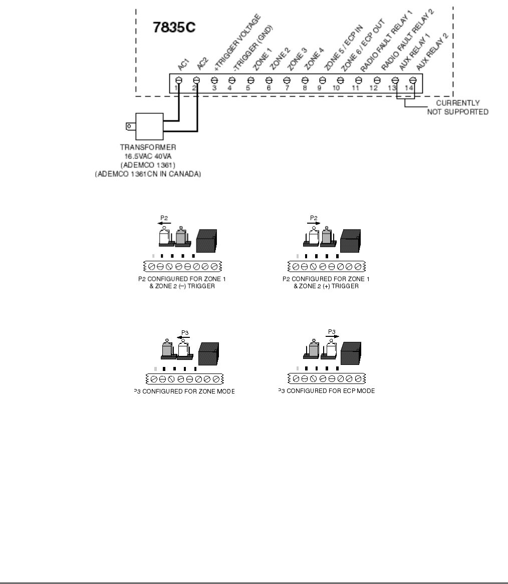
For zone operation, set the jumper on P3 for Z5 and Z6 as shown in Figure 5.
There are a total of 6 input zones available on the K3852.
• Zones 1 and 2 are selectable for either a (+V) or (GND) trigger with jumper P2.
• Zones 3, 4, 5 and 6 are set up strictly for a (+V) trigger. A positive voltage applied to these zones will
trigger an alarm. For added flexibility, each zone may be programmed individually to "invert" its input
so that a positive voltage is removed from the zone input to trigger an alarm.
– 22 –
Other zone options include:
• Telco fault input (triggered when the phone line to the control panel loses voltage).
• Open/Close reporting (triggered when the user arms and disarms the alarm control panel). An additional
monthly charge is applicable to this service.
• Steady or pulsing on input.
If using zone mode, run a wire for each input zone. A single common ground between the radio and control
is also required. The alarm and power wires must be routed through the back of the K3852. The ground
wire should be run from the alarm panel. The wire access port is located between the terminal block and the
battery on the back cover. Refer to Figure 3 for terminal block positions. Refer to the following wiring
diagrams corresponding to the installation’s configuration.
.
Figure 3. K3852 Terminal Block
Figure 4. K3852 P2 Jumper Configuration
Figure 5. K3852 P3 Jumper Configuration
Wiring and Configuring for Zone Operation
To trip a zone on the K3852, the triggering voltage from the control must be within 4.5V-14.2V. Trigger
levels above this range may cause permanent damage to the unit. Trigger levels below this range will result
in unreliable operation.
– 23 –
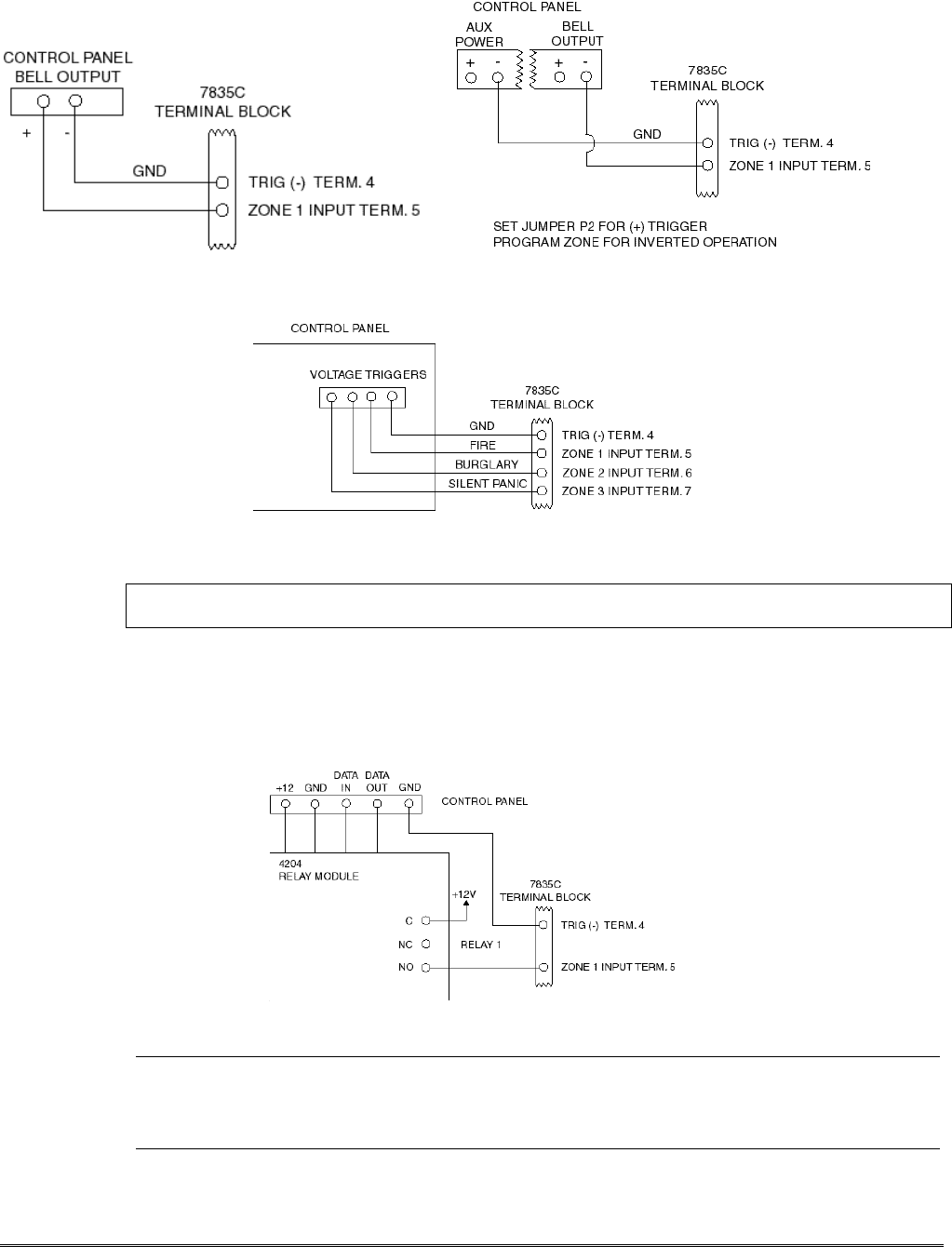
If using zone mode, connect a wire from the triggering source (bell output, voltage trigger, etc.) to each
zone on the radio to be used. Examples of zone connections are shown in Figures 6, 7 and 8.
Figure 6. Wiring the K3852 zone 1 Input to trigger on Figure 7. Wiring the K3852 zone 1 Input for
(+) Bell Output voltage ground triggered bell output
Figure 8. Wiring the K3852 zone inputs to voltage triggers, which generate
(+) voltage on each wire for different alarm conditions
NOTE: Trig (–) must be connected to the control’s electrical ground as shown in figures 6, 7, 8 9, and 10,
and not to earth ground.
If the alarm control panel is activating an output relay that will be used to apply voltage to one of the input
zones on the radio, do the following:
1. Connect the arm (common) of the relay to 12VDC.
2. Connect the N.O. contact of the relay to the input zone. When the relay is activated, voltage will be
applied to the zone, causing the radio to send its message (see Figure 9).
Figure 9. Wiring the K3852 zone 1 input to be triggered by an ADEMCO 4204 Relay Module
UL• For UL zone operation, the K3852 must be used with controls that are UL Listed.
• Bell outputs cannot be used as a zone trigger for UL installations.
• All interconnecting wiring between the K3852 and the control unit must be no longer than 3 feet.
– 24 –
Wiring and Configuring ECP Communication (ECP Options)
The K3852 supports ECP messaging to communicate directly with the control panel. An unprogrammed
radio can be set to communicate on the ECP bus at device address 3 by pressing the tamper switch during
the initial power up period. See “Programming the K3852” for details. Only certain panels support ECP
data communication at this time (i.e., ADEMCO’s VISTA-10SE, VISTA-20SE, Via-30P and
VISTA-128FB). Select this mode of operation with jumper P3. When P3 is in the ECP position, zone 5 and
zone 6 become ECP IN and ECP OUT, respectively. When using ECP, zones 1 through 3 cannot be used.
Zone 4 becomes the arm/disarm “zone,” if this feature is selected.
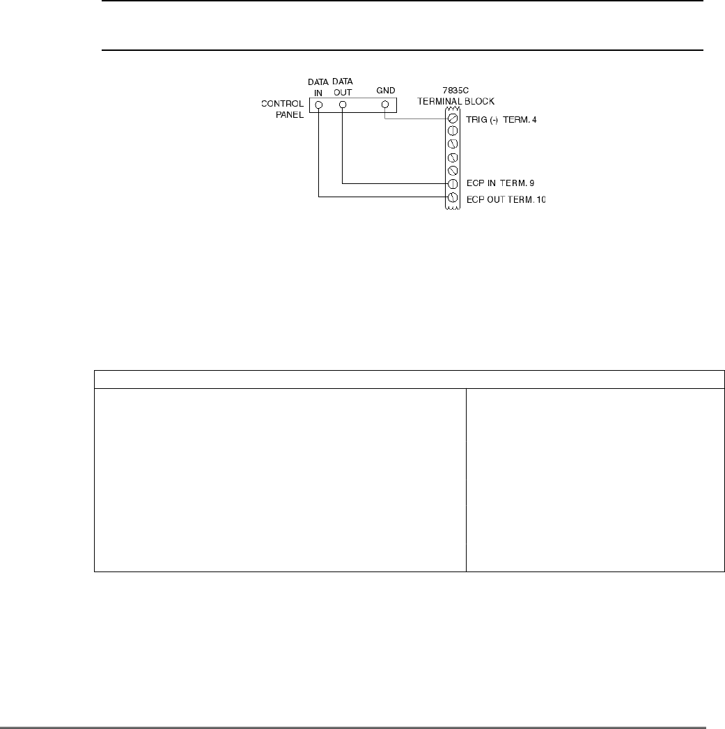
Connect the K3852 in parallel with keypads and other peripheral devices such as RF receiver, VIP module,
etc., that use ECP. To wire the radio for ECP communication, do the following:
1. Connect terminal 9 on the K3852 to Data Out terminal of the alarm control panel.
2. Connect terminal 10 on the K3852 to the Data In terminal of the alarm control panel.
3. Connect terminal 4 on the K3852 to the Ground terminal of the alarm control panel.
Wire length/gauge limitations are the same for the control panel keypads as they are for the radio. Refer to
the control panel Installation Instructions.
UL• For UL ECP installations, the K3852 must be connected to a Listed compatible control unit.
Figure 10: Wiring the K3852 for ECP data communication
ECP Status Codes
When the K3852 is configured for ECP mode, it sends status messages to the control for battery, AC
power, tamper and RF failures. The status is displayed on the control’s keypad as “Long Rnge Fail”
followed by a 4-digit code when using Ademco’s low-end control panels (Vista-10SE, Vista-20SE,
Via-30P). These code are listed below, as well as Contact ID codes sent to the central station.
Table 5. ECP Status Codes Table
Keypad Contact ID
Status Code Explanation Code* Meaning
0000 ...............Control lost communication with K3852 R330 C8xx**......Restore of RF faults
3000 ...............K3852 lost AC power ...........................(restore of peripheral trouble)
0880 ...............K3852 tamper detected (cover removed) E342 C8xx**......ECP AC loss
0060 ...............K3852 low battery R342 C8xx**......ECP AC restore
0005 ...............K3852 has lost contact with AlarmNet E338 C8xx**......ECP low battery
0009 ...............K3852 hardware failure; requires factory service R338 C8xx**......ECP low battery restore
000D...............K3852 radio account is no longer active E339 C8xx**......ECP power-on reset
000F............ K3852 is not registered; radio account not activated E341 C8xx**......ECP tamper
R341 C8xx**......ECP tamper restore
E355 C000 ........radio lost comm. with control
* as displayed on 685 Digital Receiver R355 C000........radio restore comm. w/control
** xx = K3852 device address
– 25 –
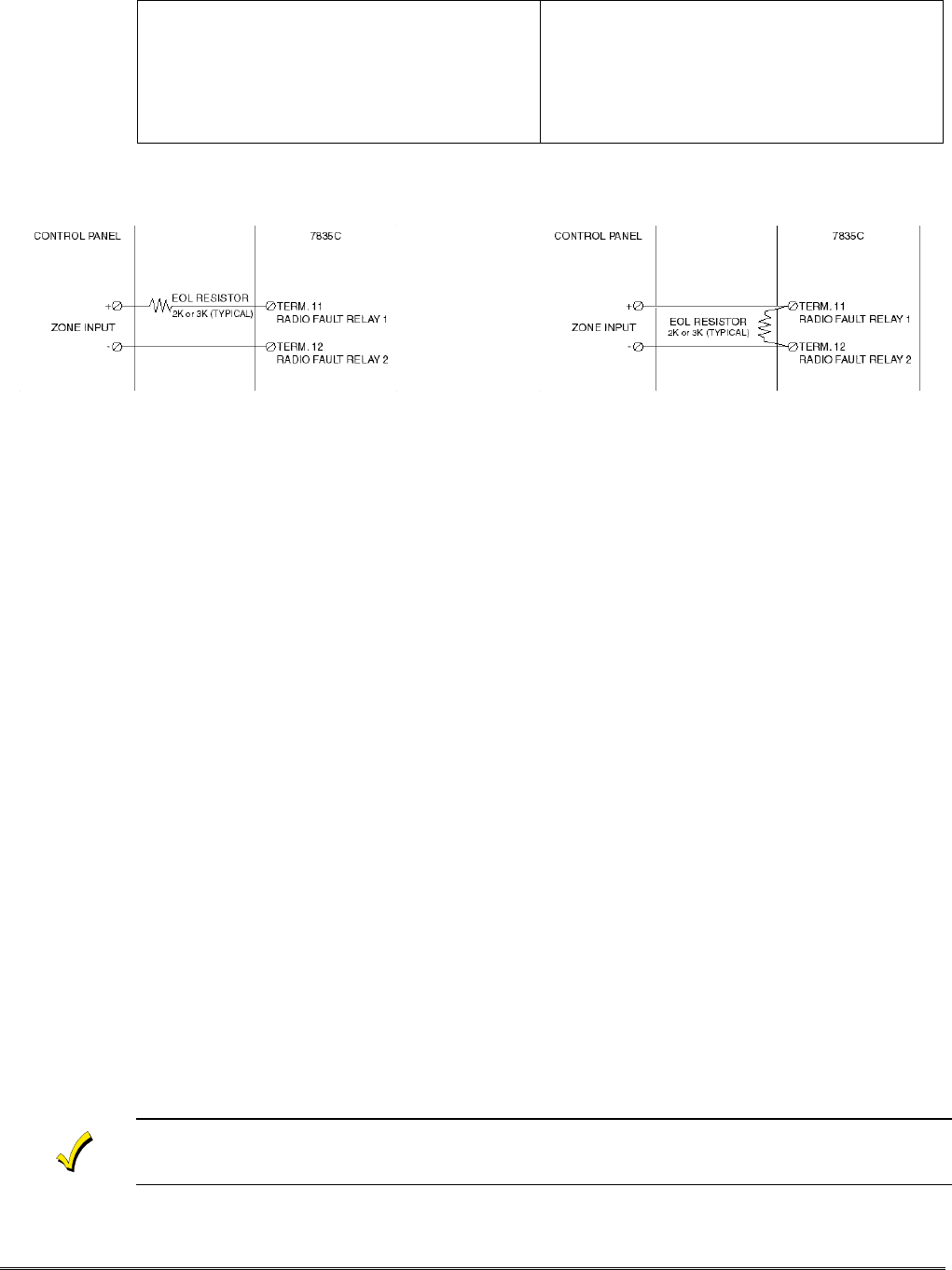
Wiring for Radio Faults
You may program the radio fault output relay (refer to Programming the K3852 section) for either:
FAIL-SAFE mode (UL requirement)
•Answer “Y” to “FLT REL ON (Y/N)”
•Relay always energized [N.C.]
•Relay will change state (and trigger a dialer, if
connected) in the event of power loss.
•Fail-safe mode increases the standby current by about
10mA, which results in lower battery backup time
(about 15%) in the event of power loss.
LOW CURRENT mode
•Answer “N” to “FLT REL ON (Y/N)”
•Relay normally de-energized [N.O.]
•Does not increase standby current
•NOT approved for UL installations.
Run two wires from the K3852’s radio fault terminals 11 and 12 to a zone on the control panel. Refer to the
Figures below for wiring the radio fault relay.
Figure 11. Wiring the K3852 to trip a control panel zone Figure 12. Wiring the K3852 to trip a
during a radio fault (required for UL installations) control panel zone for normally open fault
(not UL approved)
AC Power Connections
Primary power for the K3852 is provided by a wall-mounted 16.5VAC / 40VA transformer ADEMCO PN:
1361 (1361CN in Canada). Use of a transformer with a lower power rating will result in unreliable system
operation.
Connect the AC power wires from the 16.5V 40VA wall transformer to terminals 1 and 2 on the K3852. Do
not plug the transformer into the AC power source until all wiring connections have been made and you are
ready to power up the K3852. Refer to the K3852 Initial Power-Up Sequence section.
Backup Battery Connection
The optional battery backup (ADEMCO 7720BT) can provide over 4 hours of system life in the event of an
AC power failure. When AC power is lost, the K3852 enters a low-power state and the programmable AC
loss message can alert the AlarmNet Control Center (AC loss messages are reported within 10-40 minutes
of actual AC loss). Any alarms that are tripped during this low-power state will wake the system up to
transmit the appropriate message. After a successful transmission, the K3852 will reenter its low-power
state. When the battery reaches 10.5V, a low-battery message is transmitted, which alerts the AlarmNet
Control Center that this may be the radio’s last message. When the battery reaches 8.5V, radio
transmissions are no longer possible and the system shuts down. If AC power is restored before the system
shuts down, an AC Restore message will be sent and the battery will be recharged using the K3852’s built-
in battery charger. If AC power is restored after the system has shut down, a power-on reset condition
exists, and the radio will initialize itself as described earlier and the battery will be recharged.
The K3852 performs a battery test under load on a daily basis. During this test, if the battery drops below
10.5V, a low-battery message will be generated to indicate that the battery should be replaced.
To install the battery, snap it into the battery holder with the connector wire towards the lower right. Do not
plug the battery in until all wiring connections have been made and you are ready to power up the K3852.
Refer to K3852 Initial Power-Up Sequence section. When you are ready to power up the radio, plug the
battery connector into the battery jack located on the right-hand side of the K3852 terminal strip.
Lower cover must be in place for the K3852 to enter its lower power state during battery operation.
– 26 –
Section 7. Operation Overview
LED Indications
The K3852 has two sets of LED displays: Radio Status LEDs and a multi-function bar graph.
Radio Status: Green, yellow, and red LEDs, which provide information on pending messages,
successful or unsuccessful message transmission, network connectivity, and
registration status. Refer to Table 6 below.
Table 6. Radio Status LED Indications
LED PATTERN MEANING
Green Flash
Solid With solid yellow, successful message transmission
With flashing yellow, network contact but radio is unregistered
Yellow Solid
Flash rapidly, continuous
Flash, once per sec
Flash, twice per sec
Message pending
Waiting for message validation after successful transmission
Normal operation, connected to “B” side carrier
Normal operation, connected to “A” side carrier
Red Solid
Periodic flash
Flash rapidly, continuously
Flash rapidly, briefly
No network contact / RF fault
ECP mode only: loss of communication with control
RF fault (unsuccessful transmission) and ECP fault
Transmit error (refer to transmit error codes diagram on next
page)
LED Displays
All Solid
Rapid chaser
Slow chaser
Slow flash in unison once
per second
Slow flash in unison twice
per second
Power on, LED Test
Power on reset condition
Program mode accessible, radio previously programmed
Program mode accessible, radio previously unprogrammed,
zone defaults
Program mode accessible, radio previously unprogrammed,
ECP defaults
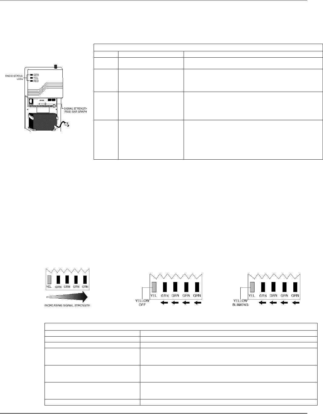
Bar Graph Indications
Signal Strength: Viewed with the cover removed (refer to Removing the Cover section),
this display consists of one yellow and four green LEDs arranged in a bar graph. It
indicates the signal strength at which the K3852 is receiving the local cell. The display
is intended as an installation aid for determining a suitable mounting location. Refer to
Selecting a Radio Installation Site section for an explanation of its use.
Power-Up: During power-up, the bar graph LEDs are used to monitor radio initialization, and is
read from right to left. Refer to the K3852 Initial Power-Up Sequence section for details.
Registration: The bar graph display also monitors the radio’s registration progress. Refer to
Registering the Radio section for detailed information.
Transmit Error: The bar graph LEDs also indicate failed message transmission error codes by the
number of lit segments. Refer to the Transmitting an Alarm paragraph on the next page
for details.
Signal Strength Bar Graph Initial Power-Up Display Radio Registration Display
Table 7. Bar Graph LED Indications
PATTERN MEANING
Solid Power on, LED Test.
Rapid chaser Power on reset condition.
From left to right, one or more LEDs are
lit, with the leading LED either solid or
blinking.
Normal RSSI display. Refer to Figure 2 and “Selecting a Suitable Installation
Site” section for a description of this display.
Yellow LED not lit, green LEDs
sequentially being lit from right to left –
counting down.
Radio initial power-up sequence. This display will only be seen when the K3852
is being powered up (refer to “Initial Power-Up” section).
Yellow is blinking, green LEDs
sequentially being lit from right to left –
counting down.
Radio registration sequence. This display will only be seen when the K3852 is
being registered. Refer to Registering the Radio section.
Flash in unison Registration unsuccessful.
– 27 –
Normal Operation
With the K3852 installed, programmed, and registered, and after a successful transmission of the Power on
Reset message, the K3852 enters normal operation. Normally, with good cellular coverage and no
messages pending, the yellow status LED will flash in one of two patterns indicating the operating carrier.
•Yellow flashing once per second indicates no alarm messages are pending and that the K3852 is
connected to a cell being operated by the “B” side carrier.
•Yellow flashing twice rapidly, then a pause every second, indicates no alarm messages are pending and
the cell that the K3852 is in contact with is operated by the “A” side carrier.
Refer to Table 6 for all LED patterns
Note that at any point during operation, a solid red LED indicates that contact with the cell has been
lost. The K3852 will automatically attempt to regain contact with the cell. If contact is not regained
before the programmed radio fault time, the radio fault relay will change state, sending a radio fault to
the panel. Refer to Table 6 for all LED patterns.
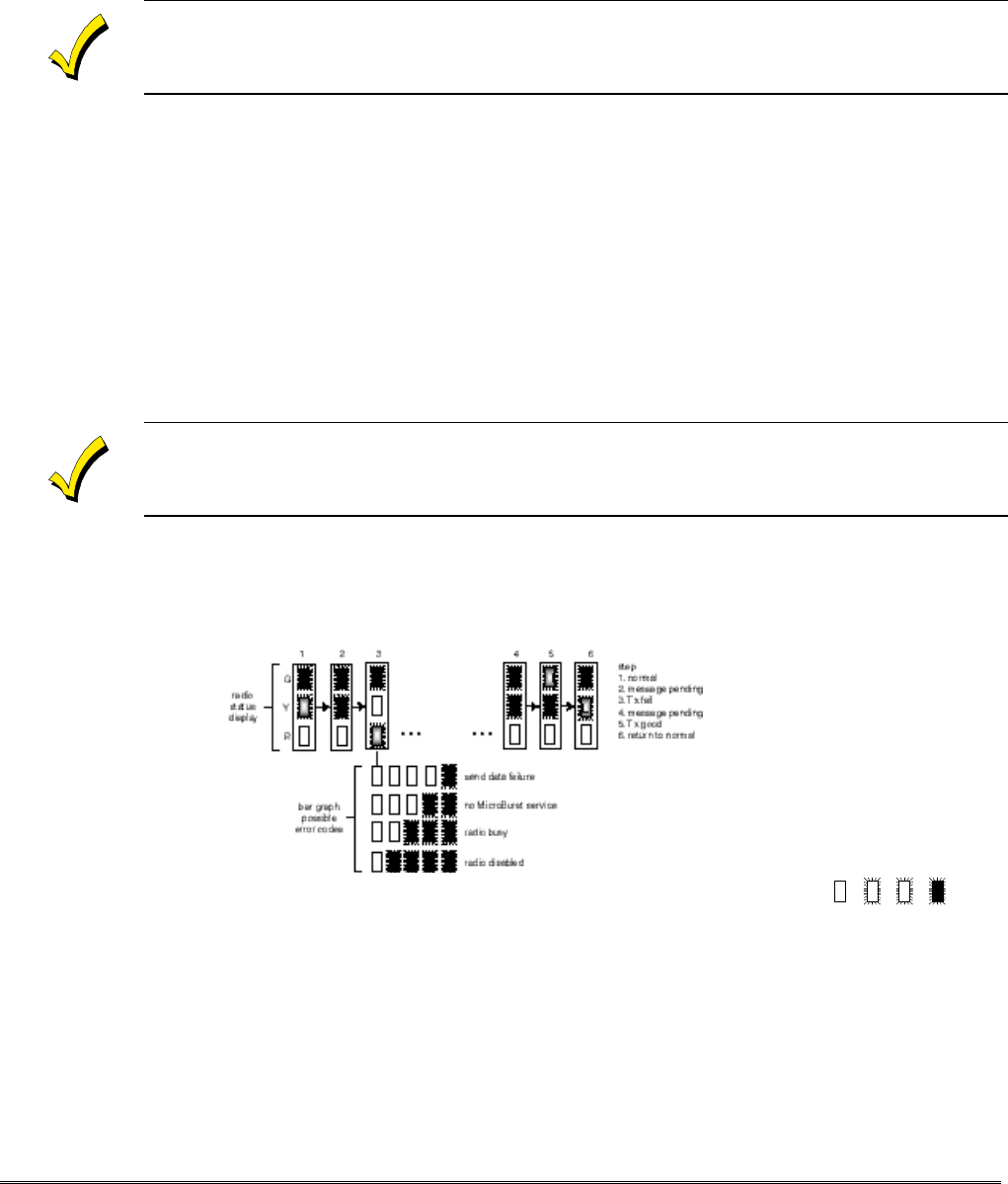
Transmitting an Alarm
While in normal operation, triggering any zone or reception of a valid ECP message will initiate the
transmission of an alarm. The yellow status LED will light solid, indicating a message pending. The green
LED will flash rapidly 8 times when the alarm message has been successfully transmitted. The yellow LED
will begin to flash rapidly, indicating the K3852 is waiting for a message validation from AlarmNet Control.
This may take several minutes to receive, since the validation is a low priority message. When the K3852
receives the validation from AlarmNet, the yellow LED resumes its normal blinking pattern. If the K3852
does not receive a validation within 90 seconds of a successful transmission, it will retransmit the alarm. The
K3852 will continue to retransmit an unvalidated alarm once every 90 seconds until the message is
validated, or the “old alarm time” has expired. If the message is not validated, the alarm is removed and the
K3852 resumes normal operation. When the zone restores, if zone restoral has been programmed, the
restoration message will be transmitted and the validation will be received with the same LED patterns.
Refer to Table 6 for LED patterns.
If an alarm is not successfully transmitted before the old alarm time expires, the radio fault relay will
go to its programmed fault state.
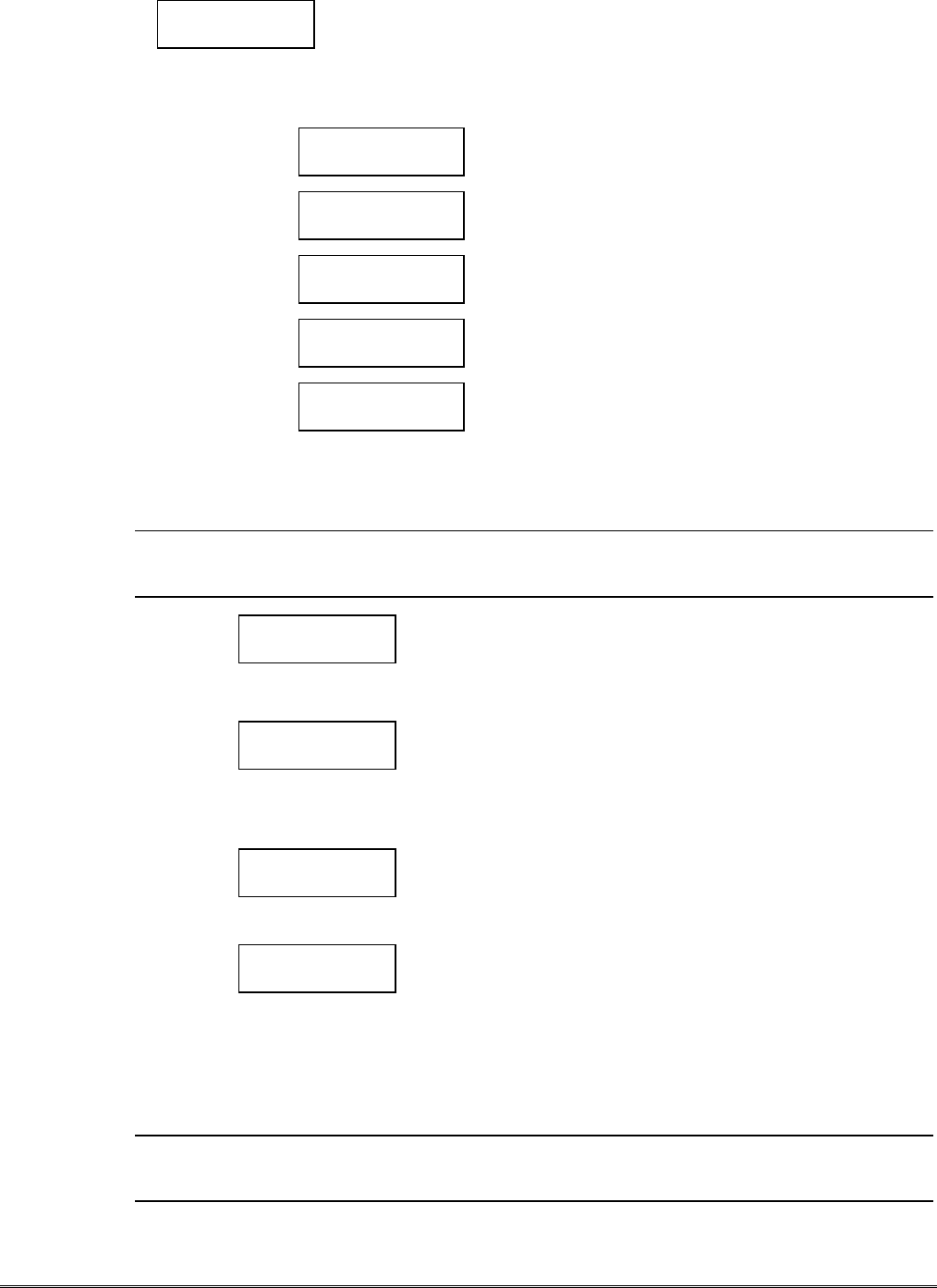
The red LED will flash 8 times and the yellow LED will remain solid any time a transmission is
unsuccessful. Additionally, the bar graph LEDs will display an error code (refer to the diagram below). The
K3852 will automatically attempt retransmission of the alarm within 10 seconds. The radio will continue
to retransmit until it is successful, unless a radio fault has been generated (the red LED lights solid on).
Refer to Table 6 for LED patterns.
LED Key:
Transmit Error Codes as Displayed on the Bar Graph off blink rapid
blink
on
(Note: Green Radio Status LED is lit, indicating an unregistered radio)
Radio Supervision
The K3852 periodically transmits supervisory and status messages to alert the network that it has
communication integrity. The supervision period (window) is a programmable feature (see Question 5). If
no messages are received by the AlarmNet Control Center during the supervisory window, a
communication failure signal is routed via RF to the appropriate AlarmNet–A or AlarmNet–M equipped
central station.

– 28 –
Section 8. Keyboard Commands
7720P Keyboard Commands
“A” K3852 x.xx
(c) Pittway 1998
Software Revision
Display the installed software Revision.
“B” NET OK -xxxDBM Z
MIN xxx-xxx-xxxx
Radio & Connectivity Display
“NET OK” indicates that the K3852 is in contact with a local cell
and AlarmNet.
“–xxxDBM” is the numeric value of the RSSI bar graph. It indicates
the power level at which the K3852 is receiving the local cell. Note:
-dBm is a measure of power; decibels less than a milliwatt. A
reading of –98DBM is a better signal than –104DBM.
“Z” = A or B carrier
“MIN xxx-xxx-xxxx” is the radio’s unique identification number
NET NS -xxxDBM Z
MIN xxx-xxx-xxxx
“NET NS” (no service) indicates the K3852 is in contact with a local
cell but has no AlarmNet service.
“Z” = A or B carrier
NO CONTACT
MIN xxx-xxx-xxxx
“NO CONTACT” indicates that the K3852 has lost contact with the
local cell and AlarmNet.
“C” NET TIME “NET TIME” displays the network time.
“E” Channel = xxx
Sys=x SID=z xxxx
Network System Display
“Channel = xxx” indicates the control channel that the K3852 is
using to communicate with the local cell.
“Sys=x” indicates the local carrier (“A” side or “B” side) that the
K3852 is connected with.
“SID=z xxxx” is the System Identification Number, the unique ID
number for each cellular carrier, where:
“z” is the international identifier code:
0 = United States
1 = other countries
2 = Canada
3 = Mexico
“xxxx” is a numeric value from 0000 – 1023
“F” A mz xxxx
B mz xxxx PREF *
Carrier Display
* = Carrier currently selected
“xxxx” is the System Identification Number
“z” = the international identifier code where:
0 = United States
1 = other countries
2 = Canada
3 = Mexico
“M” = MicroBurst service found. Blank if not found.
“PREF” = Preferred side selected in question 7
“D” Bat Test Start
Hit S to Chk
Battery Test
This selection initiates a 10-min. battery test. The charger is removed
from the battery and a load is applied for 10 min. The “S” command
can be used to monitor the battery condition throughout the test.

– 29 –
“S” 123456TmBaAcFlt
555555 6 + + 0
Status Display
The status of the K3852 can be viewed on the 7720P. The status
display includes zone input status, test terminal status, tamper status,
battery condition, charging voltage status, and radio fault status.
Status Display Interpretation for “S” Command
123456 The numbers 1-6 represent the 6 zone inputs, and follow
ADEMCO High Speed Format codes:
1New Event
2New Opening
3Restore
4New Closing
5Normal
6Previously Reported Event
@Telco New Event
PTelco Previously Reported
pTelco Restore
Tm Tamper status follows High Speed Format codes above.
Ba Represents battery condition:
+Battery voltage acceptable
–Battery voltage below 10.5V ± 5%
V Battery voltage going low has not yet been sent to the
central station (appears only briefly)
XBattery not installed
Ac Represents line voltage:
+AC line voltage OK
–AC line voltage bad & reported
VAC line voltage bad, not reported (reporting window not expired)
^AC voltage restored, not reported as restored
Flt Represents Radio Faults:
0Normal
5No contact with AlarmNet (check antenna, connections)
9Hardware failure; requires factory service
CRC RAM/EEROM corruption. Reset the radio and, if necessary,
reprogram. If this fault recurs, return radio for service.
“T” Registration
MSG 1 Sent
Test Registration
Sends a test registration to the central station, reporting as “5555
5555 9.” Functional for unregistered K3852’s only. Refer to section
5.
“T” Test Alarm Sent Test Alarm
Sends a Test alarm to AlarmNet. Functional for registered K3852’s
only.
“X” Reset (Y/N) Reset the K3852.
This will be the display following the “X” command.
Answering “N” will return to normal mode. Answering “Y” will
reset the radio and display the following:
Resetting!
“↑↑”Registration
MSG 1 Sent
Registration
Registers a programmed K3852 with AlarmNet. Refer to section 5.
“↓↓”Enter PIN # Replacement Registration
Used only when replacing an existing K3852. Refer to section 5.

– 30 –
Section 9: Troubleshooting
Problem Probable Cause Solution
K3852 not being received at the central
station. Message transmit successful;
yellow LED extinguishes, green LED
flashes 6 times.
Programming (subscriber number, central
station ID number, or city number.) Verify and correct programming entry
with the 7720P. Refer to the Programming
section.
K3852 not being received at the Central
station. Message transmit not successful.
Yellow LED is lit solid, red LED flashes 6
times.
Antenna location or installation. Remove K3852 cover, check RSSI level
with a 7720P or the bar graph. Select a
better mounting location. Refer to
“Selecting a Suitable Installation Site”.
Ensure the antenna connector is not
damaged or obstructed. Ensure the
antenna is screwed down securely.
During installation, with cover removed,
using battery power and wall transformer
not plugged in, K3852 not being received
at the central station. Message transmit
not successful. Yellow LED is lit solid, red
LED flashes 6 times.
Battery is low. Replace battery with a fully charged
battery or plug in the wall transformer.
Radio fault, solid red LED on the Radio
Status display. Antenna location or installation. Remove K3852 cover, check RSSI level
with a 7720P or the bar graph. Select a
better mounting location. Refer to
“Selecting a Suitable Installation Site”
section. Ensure the antenna connector is
not damaged or obstructed. Ensure the
antenna is screwed down securely.
Low Battery message sent with cover
installed and wall transformer installed,
during normal operation .
AC voltage supply AC power loss, excessive AC wire run, or
incorrect transformer.
Environment. If temperature exceeds -30°C to 60°C, this
will diminish battery capacity and or life.
Replace battery if required.
Tripping a zone or valid ECP message does
not generate a message pending display;
solid yellow LED
No connection ground. Connect (–) trigger output (TB Pin 4) to
the panel ground.
Incorrect trigger input. Verify type of input. Check P2 & P3
configuration.
Application of +4.5 to 12 volts (Non-
Inverted). Check programmed trigger
levels.
Absence of +4.5 to 12 volts (Inverted).
Check wiring.
Incorrect jumper settings. P2 & P3 See Setting the Jumper Options.
Radio will not initialize.
The 5 RSSI LEDs blink in unison during
initial power-up.
Data stored in EEPROM is corrupt. Connect the 7720P and enter
programming mode. Skip all programming
questions and restore factory defaults as
described in Programming section.
Radio will not register. Error in programmed features. Verify programmed options. Change as
required.

– 31 –
FEDERAL COMMUNICATIONS COMMISSION (FCC) Part 15 STATEMENT
This equipment has been tested to FCC requirements and has been found acceptable for use. The FCC requires the
following statement for your information:
This equipment generates and uses radio frequency energy and if not installed and used properly, that is, in strict
accordance with the manufacturer's instructions, may cause interference to radio and television reception. It has been
type tested and found to comply with the limits for a Class B computing device in accordance with the specifications in
Part 15 of FCC Rules, which are designed to provide reasonable protection against such interference in a residential
installation. However, there is no guarantee that interference will not occur in a particular installation. If this equipment
does cause interference to radio or television reception, which can be determined by turning the equipment off and on,
the user is encouraged to try to correct the interference by one or more of the following measures:
•If using an indoor antenna, have a quality outdoor antenna installed.
•Reorient the receiving antenna until interference is reduced or eliminated.
•Move the radio or television receiver away from the receiver/control.
•Move the antenna leads away from any wire runs to the receiver/control.
•Plug the receiver/control into a different outlet so that it and the radio or television receiver are on different branch
circuits.
If necessary, the user should consult the dealer or an experienced radio/television technician for additional suggestions.
The user or installer may find the following booklet prepared by the Federal Communications Commission helpful:
"Interference Handbook"
This booklet is available from the U.S. Government Printing Office, Washington, DC 20402.
The user shall not make any changes or modifications to the equipment unless authorized by the Installation Instructions
or User's Manual. Unauthorized changes or modifications could void the user's authority to operate the equipment.
THIS DEVICE COMPLIES WITH PART 15 OF FCC
RULES AND WITH RSS-210 OF INDUSTRY AND
SCIENCE CANADA. OPERATION IS SUBJECT TO
THE FOLLOWING TWO CONDITIONS: (1) THIS
DEVICE MAY NOT CAUSE INTERFERENCE, AND (2)
THIS DEVICE MUST ACCEPT ANY INTERFERENCE,
INCLUDING INTERFERENCE THAT MAY CAUSE
UNDESIRED OPERATION OF THIS DEVICE.
ISC: RSS/CNR 210

– 32 –
UL Requirements
Below is a list of UL requirements that must be met for UL installations.
NOTE: The K3852 is not UL Listed for fire alarm service. For fire, the K3852F can be used as the backup dialer. K3852F is
not approved for use as the primary fire dialer.
1. There are no UL Listed siren drivers available for commercial burglar alarm use.
2. When the K3852 is set for Zone Mode operation on a UL commercial burglar alarm installation, all interconnecting
wiring between the control unit and the K3852 must be no more than 3 feet in length and contained within the same
room. All interconnecting wiring must be installed in rigid conduit or EMT (where exposed on interior walls) or in
flexible metal tubing if run in the walls or ceiling.
3. The wiring method shown in Figure 11 (page 23) is required on UL installations. The Low Current Mode may not be
used on UL installations.
4. For all modes of operation, commercial burglar alarm installations must be in accordance with the National Electrical
Code and UL681, Installation and Classification of Burglar and Hold-Up Alarm Systems.
5. For all modes of operation, residential burglar alarm installations must be in accordance with the National Electrical
Code and UL1641, Installation and Classification of Residential Burglar Alarm Systems.
6. For Zone Mode operation, the K3852 must be connected to either dry contacts or voltage trigger outputs of a Listed
compatible control unit.
7. For ECP Mode, the K3852 must be connected to a Listed compatible ECP capable control unit.
8. The antenna (and thereby the K3852) may be mounted remotely from the control panel when ECP mode is used.
9. The K3852 must be programmed as follows:
a. The K3852 must be registered as described in the Installation Instructions.
b. Zones must be programmed “No” for “Pulsed” and “00” for “Delay” (Questions 9-14)
c. Enable restoral signals (Questions 21-26).
d. At least one zone must be set to provide opening and closing signals (Question 28).
e. At least one zone must be programmed to provide Telco Channel monitoring (Question 29).
f. Either zone 7 or 8 must be enabled as the Tamper zone (Question 30).
g. The Old Alarm Time must be set to 10 minutes (Question 31)
h. AC Loss Report must be enabled (Question 32).
i. Bat Present must be enabled (Question 33).
j. Fault Relay On must be enabled (Question 34).
k. 24 Hour Supervision must be enabled (Question 5).

– 33 –
– NOTES –

– 34 –
Specifications
Dimensions: .............................5” x 9.25” x 1.625” without antenna
Power: .....................................ADEMCO 1361 Transformer (16.5VAC, 40VA)
Backup Battery ........................ADEMCO 7720BT
AC Current drain: ...................Normal operation: 330mA AC
(2.0A AC peak during transmission)
Radio fault output: ...................Form A contacts rated for 0.5A, 125VAC
Input triggering levels:.............Zones 1 and 2: selectable GND or 4.5 to 14.2 volts into 10k-ohms
Zones 3-6: 4.5 to 12 volts into 10k-ohms
RF power output: .....................600mW
Frequency band: ......................833-835MHz Transmit
878-880MHz Receive
Channel separation:..................30kHz
Receiver sensitivity:.................-115dBm
Operating temp: ......................-30 to +60 deg. Celsius
Storage temp: ..........................-40 to +70 deg. Celsius
Humidity: ................................0-90% relative humidity, noncondensing
Altitude: ..................................to 10,000 ft. operating, to 40,000 ft. storage
Antenna: ..................................ADEMCO K3209 Cellular Antenna, included
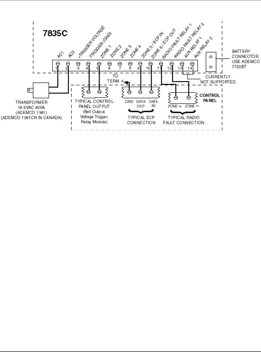
– 35 –
Summary of Connections
K3852 SUMMARY OF CONNECTIONS DIAGRAM

ADEMCO LIMITED WARRANTY
Alarm Device Manufacturing Company, a Division of Pittway Corporation, and its divisions, subsidiaries and affiliates ("Seller"), 165
Eileen Way, Syosset, New York 11791, warrants its products to be in conformance with its own plans and specifications and to be free
from defects in materials and workmanship under normal use and service for 24 months from the date stamp control on the product or, for
products not having an Ademco date stamp, for 12 months from date of original purchase unless the installation instructions or catalog sets
forth a shorter period, in which case the shorter period shall apply. Seller's obligation shall be limited to repairing or replacing, at its option,
free of charge for materials or labor, any product which is proved not in compliance with Seller's specifications or proves defective in ma-
terials or workmanship under normal use and service. Seller shall have no obligation under this Limited Warranty or otherwise if the
product is altered or improperly repaired or serviced by anyone other than Ademco factory service. For warranty service, return product
transportation prepaid, to Ademco Factory Service, 165 Eileen Way, Syosset, New York 11791.
THERE ARE NO WARRANTIES, EXPRESS OR IMPLIED, OF MERCHANTABILITY, OR FITNESS FOR A PARTICULAR
PURPOSE OR OTHERWISE, WHICH EXTEND BEYOND THE DESCRIPTION ON THE FACE HEREOF. IN NO CASE SHALL
SELLER BE LIABLE TO ANYONE FOR ANY CONSEQUENTIAL OR INCIDENTAL DAMAGES FOR BREACH OF THIS OR ANY
OTHER WARRANTY, EXPRESS OR IMPLIED, OR UPON ANY OTHER BASIS OF LIABILITY WHATSOEVER, EVEN IF THE
LOSS OR DAMAGE IS CAUSED BY THE SELLER'S OWN NEGLIGENCE OR FAULT.
Seller does not represent that the products it sells may not be compromised or circumvented; that the products will prevent any personal
injury or property loss by burglary, robbery, fire or otherwise; or that the products will in all cases provide adequate warning or protection.
Customer understands that a properly installed and maintained alarm may only reduce the risk of a burglary, robbery, fire or other events
occurring without providing an alarm, but it is not insurance or a guarantee that such will not occur or that there will be no personal injury
or property loss as a result. CONSEQUENTLY, SELLER SHALL HAVE NO LIABILITY FOR ANY PERSONAL INJURY,
PROPERTY DAMAGE OR OTHER LOSS BASED ON A CLAIM THE PRODUCT FAILED TO GIVE WARNING. HOWEVER, IF
SELLER IS HELD LIABLE, WHETHER DIRECTLY OR INDIRECTLY, FOR ANY LOSS OR DAMAGE ARISING UNDER THIS
LIMITED WARRANTY OR OTHERWISE, REGARDLESS OF CAUSE OR ORIGIN, SELLER'S MAXIMUM LIABILITY SHALL
NOT IN ANY CASE EXCEED THE PURCHASE PRICE OF THE PRODUCT, WHICH SHALL BE THE COMPLETE AND EX-
CLUSIVE REMEDY AGAINST SELLER. This warranty replaces any previous warranties and is the only warranty made by Seller on this
product. No increase or alteration, written or verbal, of the obligations of this Limited Warranty is authorized.
165 Eileen Way, Syosset, NY 11791
Copyright © 1998 PITTWAY CORPORATION
ÊK3204V16Š
K3204V1 2/99