Advance Multimedia Internet Technology CPE-IDUNG-4D1W Wireless 11g Networking product User Manual Part 1
Advance Multimedia Internet Technology Inc. Wireless 11g Networking product Users Manual Part 1
Contents
- 1. Users Manual Part 1
- 2. Users Manual Part 2
Users Manual Part 1

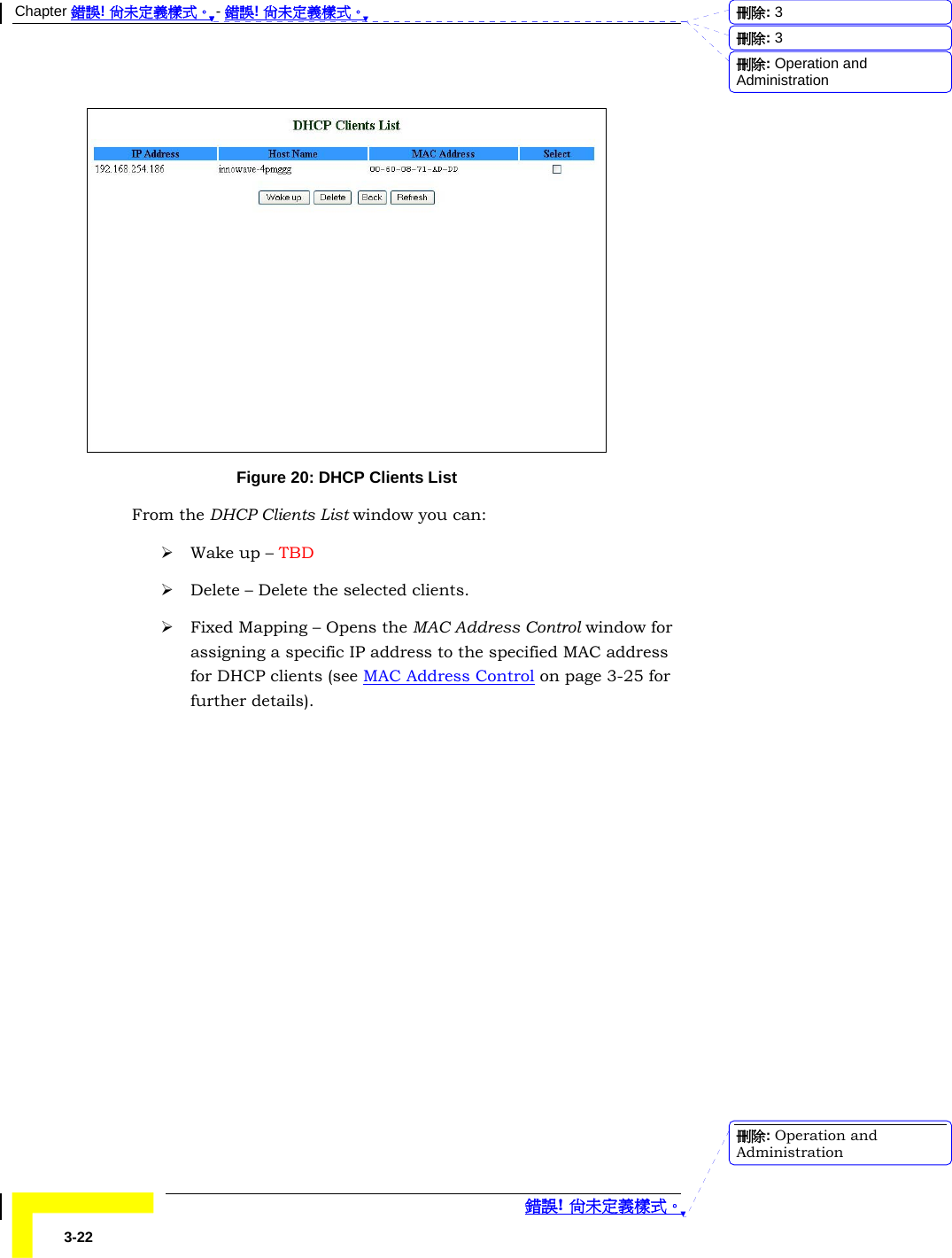
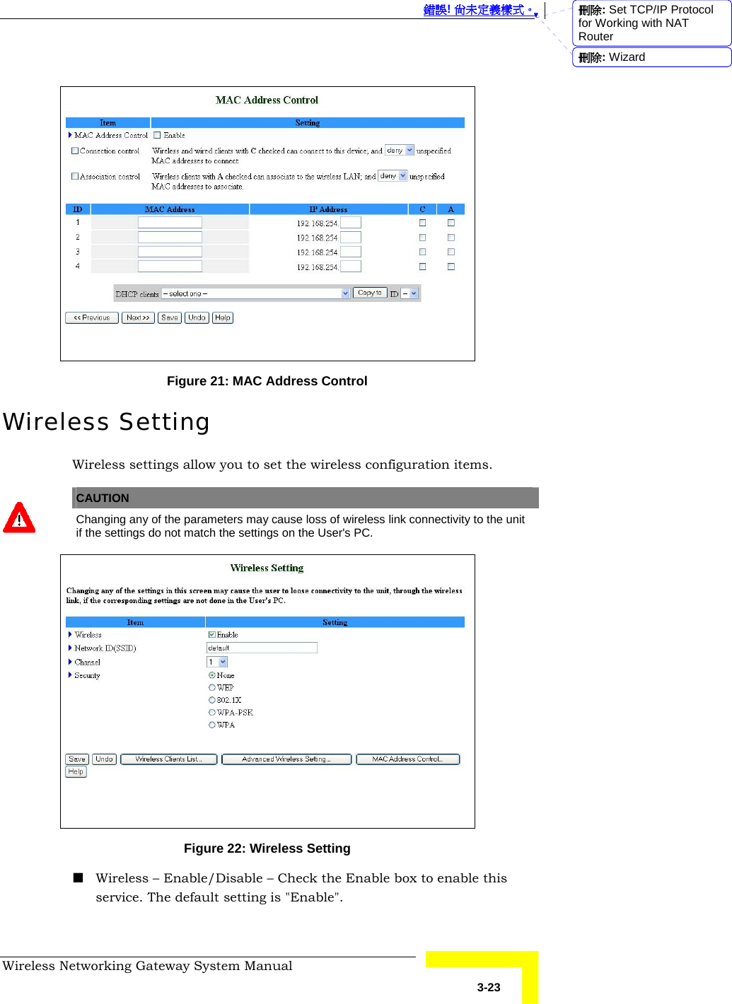
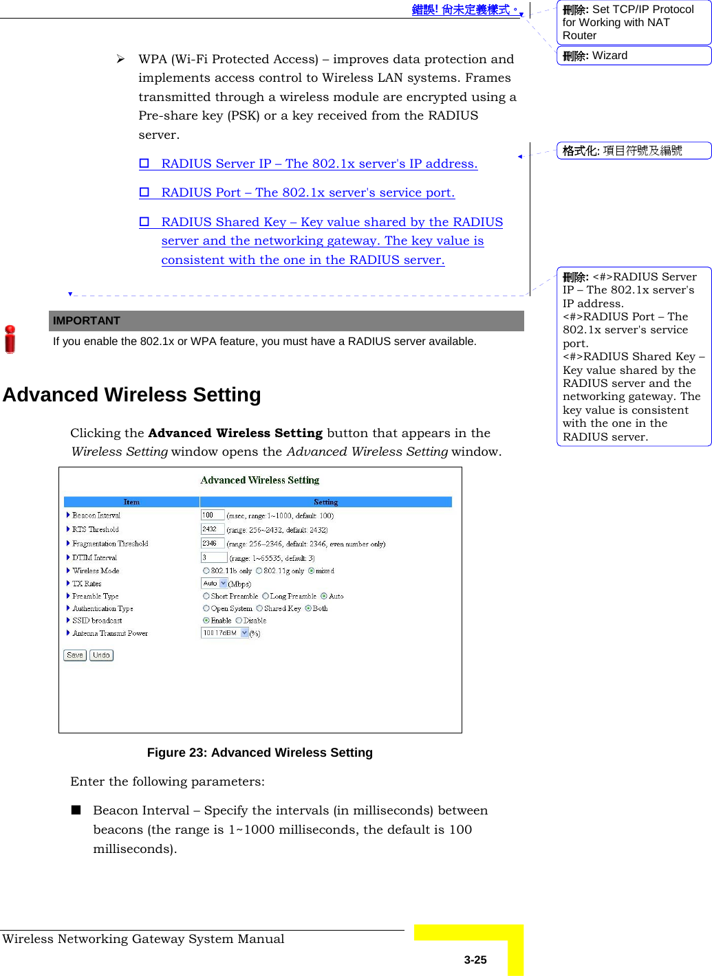
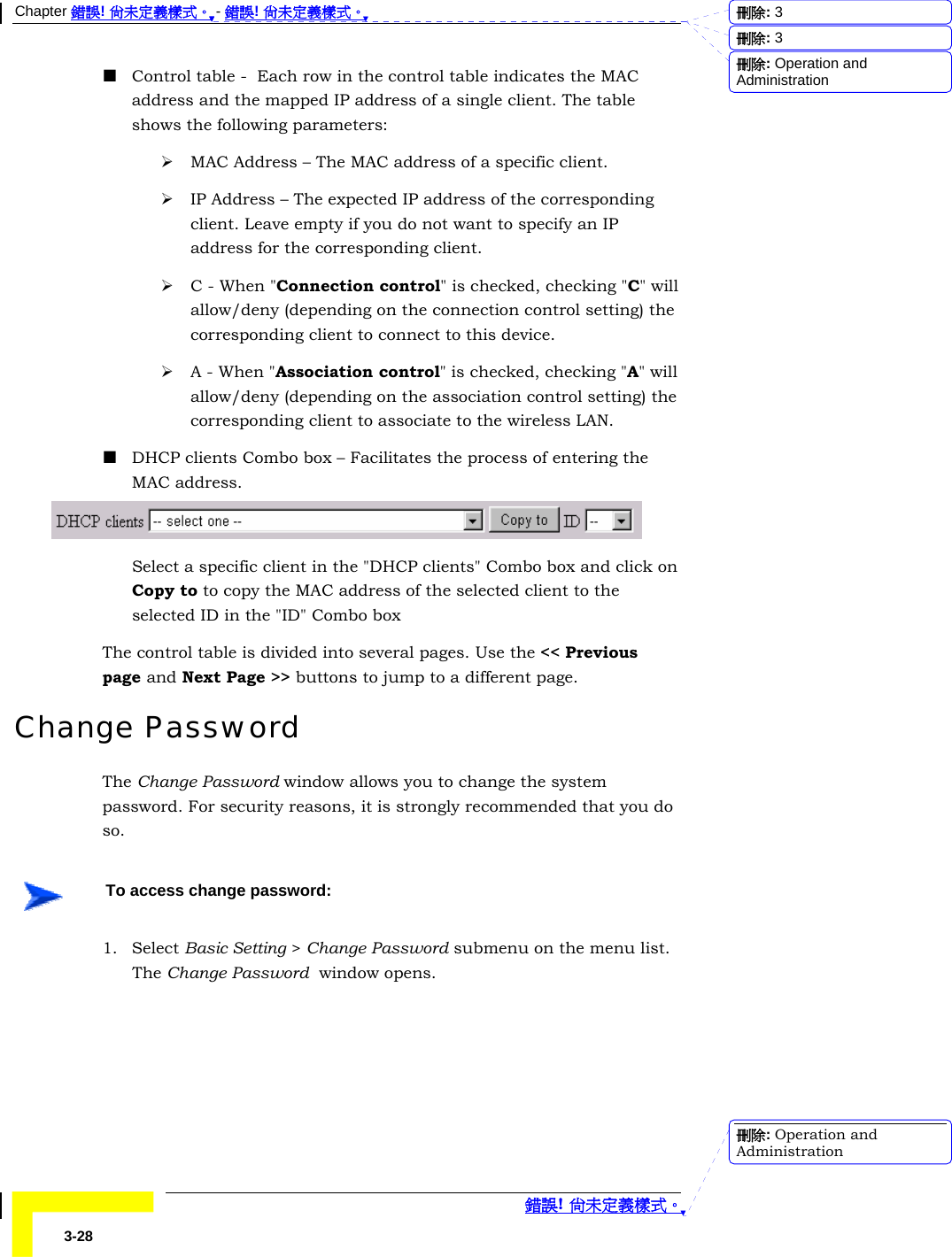
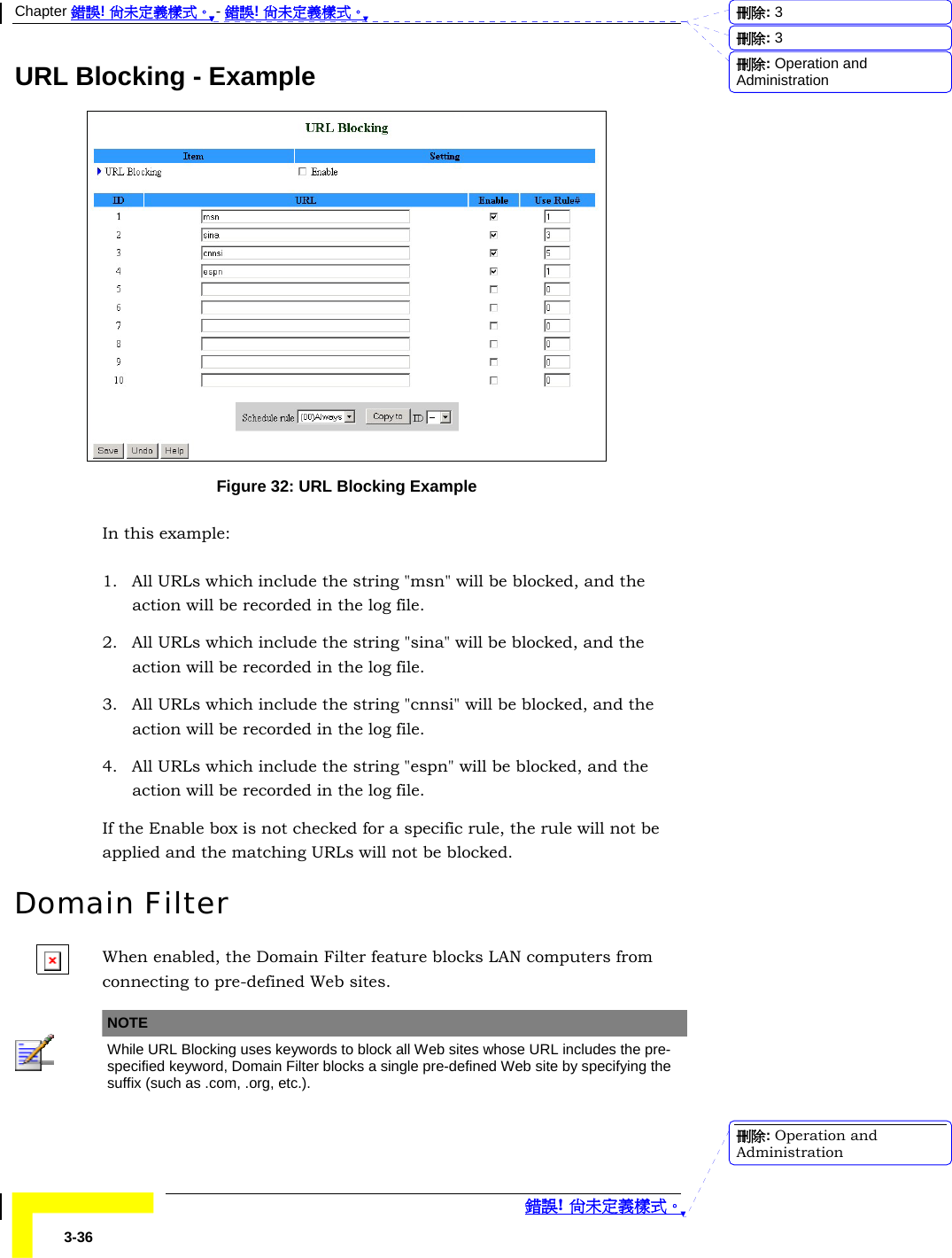
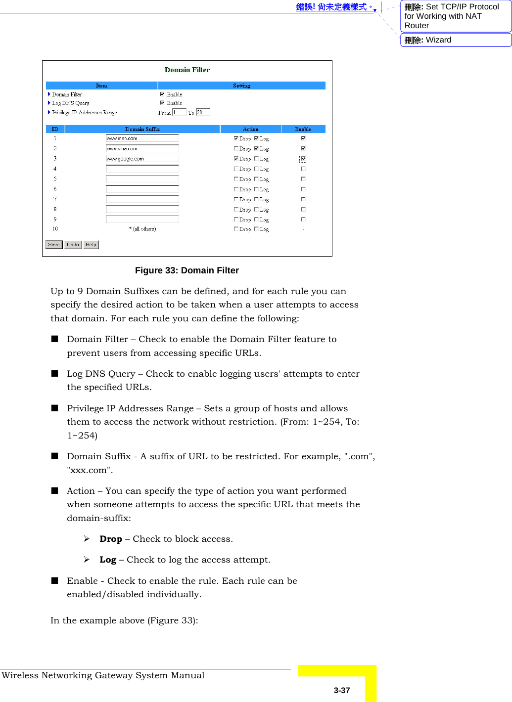
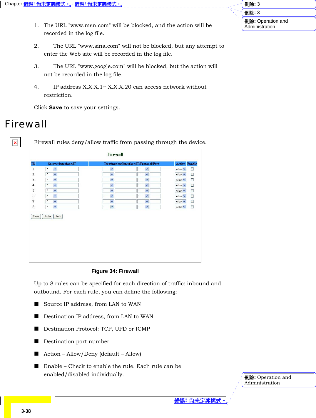
![Chapter 錯誤! 尚未定義樣式。 - 錯誤! 尚未定義樣式。 錯誤! 尚未定義樣式。 3-26 RTS Threshold – Specify the packet size above which a Request To Send will be performed (the range is 256~2432, the default is 2432). Fragmentation Threshold – Specify the packet size above which fragmentation will be performed (the range is 256~2346 even numbers only, the default is 2346). DTIM Interval – [TBD] Wireless Mode – The wireless mode supported: 802.11b, 802.11g, or both. TX Rates – Select the transmission rate from the dropdown list. Preamble Type – Select short/long or automatic preamble to be assigned to each packet. Authentication Type – [TBD] SSID Broadcast – [TBD what is SSID?] Enable/Disable broadcasting the network's ID. Antenna Transmit Power – Select the antenna's transmission power from the dropdown list. MAC Address Control MAC Address Control allows you to assign different access rights for different users and to assign a fixed IP address to a specific MAC address. NOTE All the settings in this page will take effect only when MAC Address Control is set to "Enable". 刪除: 3刪除: 3刪除: Operation and Administration刪除: Operation and Administration](https://usermanual.wiki/Advance-Multimedia-Internet-Technology/CPE-IDUNG-4D1W.Users-Manual-Part-1/User-Guide-516597-Page-62.png)
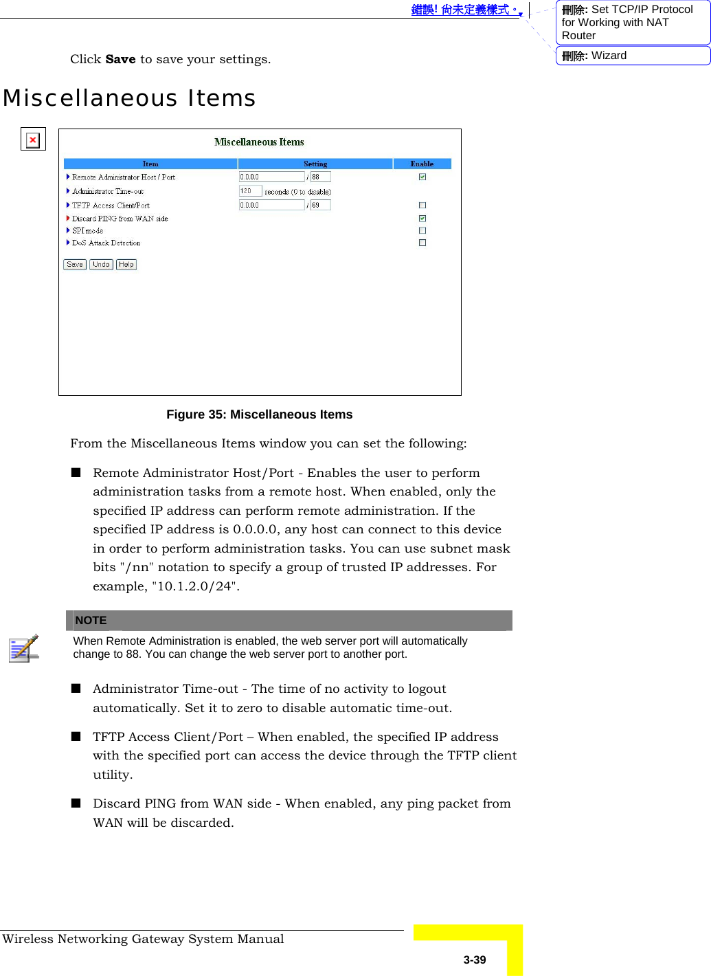
![錯誤! 尚未定義樣式。 Wireless Networking Gateway System Manual 3-27 MAC Address Control – Check "Enable" to enable the MAC Address Control feature. Connection control – Check the "Connection control" check box to enable controlling which wired and wireless clients can connect to this device. If a client is denied the connection to this device, he will not be able to access the Internet either. Select allow/deny to allow or deny clients whose MAC addresses are not in the "Control table" (see below) to connect to this device. ("deny" is the default setting.) A wired client who is allowed to connect to the device has full access to the Internet and to network resources. When denied the connection to the device, he can communicate with other clients on the wired LAN, but cannot connect to the Internet, use the Print Server function, communicate with clients on the wireless LAN, or use the Web configuration. Association control – "Association" refers to the exchanging of information between wireless clients and the device to establish a link between them. A wireless client is able to transmit and receive data to the device only after successful association. Check "Association control" check box to control which wireless clients can associate to the wireless LAN. If a client is denied the association to the wireless LAN, he will not be able to send or receive any data via this device. Select allow/deny to allow or deny clients whose MAC addresses are not in the "Control table" to associate to the wireless LAN. A wireless client who is allowed both to associate to the wireless LAN and to connect to the device has full access to the Internet and to network resources. When allowed to associate to the wireless LAN, but denied to connect to the device, he can communicate with other clients on the LAN (wired and wireless), but cannot connect to the Internet, use the Print Server function, or use the Web configuration. When denied to associate to the wireless LAN, the client cannot communicate with other clients on the LAN (wired or wireless), connect to the internet, use the Print Server function, or use the Web configuration. [TBD – provide a summary table] NOTE Association control does not affect wired clients. 刪除: Set TCP/IP Protocol for Working with NAT Router刪除: Wizard](https://usermanual.wiki/Advance-Multimedia-Internet-Technology/CPE-IDUNG-4D1W.Users-Manual-Part-1/User-Guide-516597-Page-63.png)