Advance Multimedia Internet Technology CPE-IDUNG-4D1W Wireless 11g Networking product User Manual Part 1
Advance Multimedia Internet Technology Inc. Wireless 11g Networking product Users Manual Part 1
Contents
- 1. Users Manual Part 1
- 2. Users Manual Part 2
Users Manual Part 1

SW Version 2.0
November 2004
P/N 213930
System Manual
Wireless Networking Gateway

錯誤! 所指定的樣式的文字不存在文件中。錯誤! 尚未定義樣式。
Wireless Networking Gateway System Manual
ii
刪除: Error! No text of
specified style in document.
刪除: Product Description

Legal Rights
Wireless Networking Gateway System Manual
iii
Legal Rights
© Copyright Alvarion Ltd. (“Alvarion”). All rights reserved.
The material contained herein is proprietary, privileged, and
confidential. No disclosure thereof shall be made to third parties
without the express written permission of Alvarion.
Alvarion reserves the right to alter the equipment specifications and
descriptions in this publication without prior notice. No part of this
publication shall be deemed to be part of any contract or warranty
unless specifically incorporated by reference into such contract or
warranty.
Trade Names
Alvarion, BreezeCOM, WALKair, WALKnet, BreezeNET, BreezeMANAGE,
BreezeACCESS, BreezeMAX, AlvariSTAR, MGW, eMGW and/or other
products and/or services referenced here in are either registered
trademarks, trademarks or service marks of Alvarion.
All other names are or may be the trademarks of their respective owners.
Statement of Conditions
The information contained in this manual is subject to change without
notice. Alvarion. shall not be liable for errors contained herein or for
incidental or consequential damages in connection with the furnishing,
performance, or use of this manual or equipment supplied with it.
Warranties and Disclaimers
All Alvarion products purchased from Alvarion or through any of
Alvarion’s authorized resellers are subject to the following warranty and
product liability terms and conditions.
Exclusive Warranty
Alvarion warrants that the Product hardware it supplies and the
tangible media on which any software is installed, under normal use
and conditions, will be free from significant defects in materials and
workmanship for a period of fourteen (14) months from the date of
shipment of a given Product to Purchaser (the “Warranty Period”).
Alvarion will, at its sole option and as Purchaser’s sole remedy, repair or
replace any defective Product in accordance with Alvarion’ standard
RMA procedure.

Legal Rights
Wireless Networking Gateway System Manual
iv
Disclaimer
(a) UNITS OF PRODUCT (INCLUDING ALL THE SOFTWARE)
DELIVERED TO PURCHASER HEREUNDER ARE NOT FAULT-
TOLERANT AND ARE NOT DESIGNED, MANUFACTURED OR
INTENDED FOR USE OR RESALE IN APPLICATIONS WHERE THE
FAILURE, MALFUNCTION OR INACCURACY OF PRODUCTS CARRIES A
RISK OF DEATH OR BODILY INJURY OR SEVERE PHYSICAL OR
ENVIRONMENTAL DAMAGE (“HIGH RISK ACTIVITIES”). HIGH RISK
ACTIVITIES MAY INCLUDE, BUT ARE NOT LIMITED TO, USE AS PART
OF ON LINE CONTROL SYSTEMS IN HAZARDOUS ENVIRONMENTS
REQUIRING FAIL SAFE PERFORMANCE, SUCH AS IN THE
OPERATION OF NUCLEAR FACILITIES, AIRCRAFT NAVIGATION OR
COMMUNICATION SYSTEMS, AIR TRAFFIC CONTROL, LIFE SUPPORT
MACHINES, WEAPONS SYSTEMS OR OTHER APPLICATIONS
REPRESENTING A SIMILAR DEGREE OF POTENTIAL HAZARD.
ALVARION SPECIFICALLY DISCLAIMS ANY EXPRESS OR IMPLIED
WARRANTY OF FITNESS FOR HIGH RISK ACTIVITIES.
(b) PURCHASER’S SOLE REMEDY FOR BREACH OF THE EXPRESS
WARRANTIES ABOVE SHALL BE REPLACEMENT OR REFUND OF THE
PURCHASE PRICE AS SPECIFIED ABOVE, AT ALVARION’S OPTION. TO
THE FULLEST EXTENT ALLOWED BY LAW, THE WARRANTIES AND
REMEDIES SET FORTH IN THIS AGREEMENT ARE EXCLUSIVE AND
IN LIEU OF ALL OTHER WARRANTIES OR CONDITIONS, EXPRESS OR
IMPLIED, EITHER IN FACT OR BY OPERATION OF LAW, STATUTORY
OR OTHERWISE, INCLUDING BUT NOT LIMITED TO WARRANTIES,
TERMS OR CONDITIONS OF MERCHANTABILITY, FITNESS FOR A
PARTICULAR PURPOSE, SATISFACTORY QUALITY,
CORRESPONDENCE WITH DESCRIPTION, NON INFRINGEMENT, AND
ACCURACY OF INFORMATION GENERATED. ALL OF WHICH ARE
EXPRESSLY DISCLAIMED. ALVARION’ WARRANTIES HEREIN RUN
ONLY TO PURCHASER, AND ARE NOT EXTENDED TO ANY THIRD
PARTIES. ALVARION NEITHER ASSUMES NOR AUTHORIZES ANY
OTHER PERSON TO ASSUME FOR IT ANY OTHER LIABILITY IN
CONNECTION WITH THE SALE, INSTALLATION, MAINTENANCE OR
USE OF ITS PRODUCTS.

Legal Rights
Wireless Networking Gateway System Manual
v
(c) ALVARION SHALL NOT BE LIABLE UNDER THIS WARRANTY IF ITS
TESTING AND EXAMINATION DISCLOSE THAT THE ALLEGED
DEFECT IN THE PRODUCT DOES NOT EXIST OR WAS CAUSED BY
PURCHASER’S OR ANY THIRD PERSON'S MISUSE, NEGLIGENCE,
IMPROPER INSTALLATION OR IMPROPER TESTING, UNAUTHORIZED
ATTEMPTS TO REPAIR, OR ANY OTHER CAUSE BEYOND THE RANGE
OF THE INTENDED USE, OR BY ACCIDENT, FIRE, LIGHTNING OR
OTHER HAZARD.
Limitation of Liability
(a) ALVARION SHALL NOT BE LIABLE TO THE PURCHASER OR TO
ANY THIRD PARTY, FOR ANY LOSS OF PROFITS, LOSS OF USE,
INTERRUPTION OF BUSINESS OR FOR ANY INDIRECT, SPECIAL,
INCIDENTAL, PUNITIVE OR CONSEQUENTIAL DAMAGES OF ANY
KIND, WHETHER ARISING UNDER BREACH OF CONTRACT, TORT
(INCLUDING NEGLIGENCE), STRICT LIABILITY OR OTHERWISE AND
WHETHER BASED ON THIS AGREEMENT OR OTHERWISE, EVEN IF
ADVISED OF THE POSSIBILITY OF SUCH DAMAGES.
(b) TO THE EXTENT PERMITTED BY APPLICABLE LAW, IN NO EVENT
SHALL THE LIABILITY FOR DAMAGES HEREUNDER OF ALVARION OR
ITS EMPLOYEES OR AGENTS EXCEED THE PURCHASE PRICE PAID
FOR THE PRODUCT BY PURCHASER, NOR SHALL THE AGGREGATE
LIABILITY FOR DAMAGES TO ALL PARTIES REGARDING ANY
PRODUCT EXCEED THE PURCHASE PRICE PAID FOR THAT
PRODUCT BY THAT PARTY (EXCEPT IN THE CASE OF A BREACH OF A
PARTY’S CONFIDENTIALITY OBLIGATIONS).
Electronic Emission Notices
This device complies with Part 15 of the FCC rules, ETSI 300 328, UL,
UL/C, TUV/GS, and CE.
Operation is subject to the following two conditions:
1. This device may not cause harmful interference.
2. This device must accept any interference received, including
interference that may cause undesired operation.

Legal Rights
Wireless Networking Gateway System Manual
vi
FCC Radio Frequency Interference Statement
The Subscriber Unit equipment has been tested and found to comply
with the limits for a class B digital device, pursuant to part 15 of the
FCC rules and to EN 301 489-1 rules. These limits are designed to
provide reasonable protection against harmful interference when the
equipment is operated in a residential environment notwithstanding use
in commercial, business and industrial environments. This equipment
generates, uses, and can radiate radio frequency energy and, if not
installed and used in accordance with the instruction manual, may
cause harmful interference to radio communications.
Safety Considerations
For the following safety considerations, “Instrument” means the
Wireless Networking Gateway units and its cables.
Caution
To avoid electrical shock, do not perform any servicing unless you are
qualified to do so.
Line Voltage
Before connecting this instrument to the power line, make sure that the
voltage of the power source matches the requirements of the instrument.

Important Notice
Wireless Networking Gateway System Manual
vii
Important Notice
This user manual is delivered subject to the following conditions and
restrictions:
This manual contains proprietary information belonging to Alvarion.
Such information is supplied solely for the purpose of assisting
properly authorized users of the respective Alvarion products.
No part of its contents may be used for any other purpose, disclosed
to any person or firm or reproduced by any means, electronic and
mechanical, without the express prior written permission of Alvarion.
The text and graphics are for the purpose of illustration and
reference only. The specifications on which they are based are
subject to change without notice.
The software described in this document is furnished under a
license. The software may be used or copied only in accordance with
the terms of that license.
Information in this document is subject to change without notice.
Corporate and individual names and data used in examples herein
are fictitious unless otherwise noted.
Alvarion reserves the right to alter the equipment specifications and
descriptions in this publication without prior notice. No part of this
publication shall be deemed to be part of any contract or warranty
unless specifically incorporated by reference into such contract or
warranty.
The information contained herein is merely descriptive in nature,
and does not constitute an offer for the sale of the product described
herein.
Any changes or modifications of equipment, including opening of the
equipment not expressly approved by Alvarion will void equipment
warranty and any repair thereafter shall be charged for. It could also
void the user’s authority to operate the equipment.
Some of the equipment provided by Alvarion and specified in this
manual, is manufactured and warranted by third parties. All such
equipment must be installed and handled in full compliance with the
instructions provided by such manufacturers as attached to this
manual or provided thereafter by Alvarion or the manufacturers.
Non-compliance with such instructions may result in serious damage
and/or bodily harm and/or void the user’s authority to operate the
equipment and/or revoke the warranty provided by such manufacturer.

Important Notice
Wireless Networking Gateway System Manual
viii
This page is intentionally left blank.

About this Manual
This manual contains the following chapters:
Chapter 1 – Product Description: Describes the Wireless
Networking Gateway and its components.
Chapter 2 – Installation: Describes how to install the system and
its components.
Chapter 3 – Operation and Administration: Describes how to use
the web-based management application for configuring parameters
and managing the Wireless Networking Gateway.
Appendix A – Print Server: Describes how to configure the printer
server.
Appendix B – TCP/IP Configuration for Windows 95/98:
Describes how to configure TCP/IP settings for the computers
connected to the unit.
Appendix C – 802.1x Setting.

About this Manual
Wireless Networking Gateway System Manual
x
This page is intentionally left blank.
刪除: Contents

Contents
C
Ch
ha
ap
pt
te
er
r
1
1
-
- Product Description..............................................................1-1
Introducing the Wireless Networking Gateway IDU .................................. 1-2
Functions and Features .......................................................................... 1-3
Router Basic Functions ................................................................................ 1-3
Wireless Functions....................................................................................... 1-4
Security Functions ....................................................................................... 1-4
Advanced Functions..................................................................................... 1-5
Specifications ......................................................................................... 1-6
Radio Specifications ..................................................................................... 1-6
Regulatory Standards Compliance................................................................ 1-6
Environmental ............................................................................................. 1-7
Mechanical................................................................................................... 1-7
Electrical...................................................................................................... 1-7
C
Ch
ha
ap
pt
te
er
r
2
2
-
- Installation.............................................................................2-1
Installation Requirements....................................................................... 2-2
Packing List ................................................................................................. 2-2
Additional Installation Requirements............................................................ 2-2
Panels Layout and Components .............................................................. 2-3
Front Panel .................................................................................................. 2-3
Front Panel LEDs ...................................................................................... 2-3
RESET ROUTER Button ............................................................................ 2-4
Resetting the IDU to Factory Defaults........................................................ 2-4
Rear Panel Components ............................................................................... 2-5
Rear Panel Connectors .............................................................................. 2-5
RESET ODU Button .................................................................................. 2-5
Installation............................................................................................. 2-6
C
Ch
ha
ap
pt
te
er
r
3
3
-
- Operation and Administration .............................................3-1

Contents
Wireless Networking Gateway System Manual
xii
Introduction ........................................................................................... 3-2
Control Buttons .................................................................. 錯誤! 尚未定義書籤。
Accessing the Web Configuration Server.................................................. 3-3
Log in and Log out .................................................................................. 3-4
The Menu List...............................................................................................3-5
Control Buttons ............................................................................................3-5
Status..................................................................................................... 3-7
Wizard .................................................................................................... 3-9
Basic Setting ........................................................................................ 3-11
WAN Setup .................................................................................................3-11
Static IP Address......................................................................................3-14
Dynamic IP Address .................................................................................3-15
Dynamic IP Address with Road Runner Session Management ..................3-16
PPP over Ethernet ....................................................................................3-17
PPTP ........................................................................................................3-19
LAN Setup ..................................................................................................3-20
Wireless Setting ..........................................................................................3-23
Advanced Wireless Setting .......................................................................3-25
MAC Address Control...............................................................................3-26
Change Password .......................................................................................3-28
Security Setting.................................................................................... 3-30
MAC Control...............................................................................................3-30
Packet Filters..............................................................................................3-30
Inbound Filter..........................................................................................3-32
Outbound Filter .......................................................................................3-33
URL Blocking..............................................................................................3-35
URL Blocking - Example ..........................................................................3-36
Domain Filter .............................................................................................3-36
Firewall.......................................................................................................3-38
Miscellaneous Items ...................................................................................3-39
NAT Setting .......................................................................................... 3-41
Virtual Server .............................................................................................3-41
Special AP...................................................................................................3-42
DMZ Host ...................................................................................................3-43
VPN Pass Through ......................................................................................3-44
Advanced Settings ................................................................................ 3-45
System Time ...............................................................................................3-45
System Log .................................................................................................3-46
刪除: Contents
刪除: Error! Bookmark not
defined.

Contents
Wireless Networking Gateway System Manual
xiii
Dynamic DNS............................................................................................. 3-48
SNMP Setting ............................................................................................. 3-49
Routing Table............................................................................................. 3-50
Schedule Rule ............................................................................................ 3-52
Toolbox ................................................................................................ 3-56
View Log..................................................................................................... 3-56
Firmware Upgrade...................................................................................... 3-57
Backup Setting........................................................................................... 3-58
Reset to Default.......................................................................................... 3-58
Reboot........................................................................................................ 3-59
DRAP ......................................................................................................... 3-59
Miscellaneous Items ................................................................................... 3-60
Web Configuration Server’s Parameters Summary ................................. 3-61
C
Ch
ha
ap
pt
te
er
r
4
4
-
- Glossary.................................................................................4-1
Appendix A - Print Server ....................................................................... A-1
Configuring on Windows 95/98 Platforms ............................................... A-2
Configuring on Windows NT Platforms..................................................... A-6
Configuring on Windows 2000 and XP Platforms ..................................... A-8
Configuring on Apple PC ....................................................................... A-13
TBD – what about UNIX? ....................................................................... A-15
Appendix B - TCP/IP Configuration for Windows 95/98 ...........................1
Installing TCP/IP Protocol on Your PC ....................................................... 2
Set TCP/IP Protocol for Working with NAT Router ..................................... 3
Appendix C - 802.1x Setting .......................................................................1
刪除: Contents

Contents
Wireless Networking Gateway System Manual
xiv
This page is intentionally left blank.
刪除: Contents

Figures
Figure 2-1: Front Panel ...................................................................................... 2-3
Figure 2-2: Rear Panel (without antenna) ........................................................... 2-5
Figure 3: Log In Window .................................................................................... 3-4
Figure 4: Networking Gateway Main Window...................................................... 3-5
Figure 5: System Status..................................................................................... 3-7
Figure 6: Setup Wizard ...................................................................................... 3-9
Figure 7: Setup Wizard - Select WAN Type ......................................................... 3-9
Figure 8: Setup Wizard - Configuration Completed........................................... 3-10
Figure 9: Basic Setting..................................................................................... 3-11
Figure 10: WAN Setup/Primary Setup.............................................................. 3-12
Figure 11: Choose WAN Type ........................................................................... 3-13
Figure 12: Primary Setup - Static IP Address ................................................... 3-14
Figure 13: Primary Setup - Dynamic IP Address............................................... 3-15
Figure 14: Primary Setup - Dynamic IP Address with Road Runner Session
Management.............................................................................................. 3-16
Figure 15: Primary Setup - PPPoE.................................................................... 3-17
Figure 16: Primary Setup - PPTP...................................................................... 3-19
Figure 17: Virtual Computers ............................................................................ 3-6
Figure 18: LAN Setup....................................................................................... 3-20
Figure 19: LAN Setup - DHCP Enabled ............................................................ 3-21
Figure 20: DHCP Clients List ........................................................................... 3-22
Figure 21: MAC Address Control ...................................................................... 3-23
Figure 22: Wireless Setting .............................................................................. 3-23

Figures
Wireless Networking Gateway System Manual
xvi
Figure 23: Advanced Wireless Setting ...............................................................3-25
Figure 24: Change Password ............................................................................3-29
Figure 25: Security Setting Window ..................................................................3-30
Figure 26: Packet Filter Initial Window .............................................................3-31
Figure 27: Inbound Packet Filter – Example 1 ..................................................3-32
Figure 28: Inbound Packet Filter - Example 2...................................................3-33
Figure 29: Outbound Packet Filter - Example 1 ................................................3-34
Figure 30: Outbound Packet Filter - Example 2 ................................................3-34
Figure 31: URL Blocking...................................................................................3-35
Figure 32: URL Blocking Example ....................................................................3-36
Figure 33: Domain Filter ..................................................................................3-37
Figure 34: Firewall ...........................................................................................3-38
Figure 35: Miscllaneous Items ..........................................................................3-39
Figure 36: NAT Setting .....................................................................................3-41
Figure 37: Virtual Server ..................................................................................3-41
Figure 38: Special Applications.........................................................................3-43
Figure 39: DMZ Host ........................................................................................3-44
Figure 40: VPN Pass Through ...........................................................................3-44
Figure 41: Advanced Setting .............................................................................3-45
Figure 42: System Time ....................................................................................3-45
Figure 43: System Log ......................................................................................3-47
Figure 44: Dynamic DNS ..................................................................................3-48
Figure 45: SNMP Setting...................................................................................3-49
Figure 46: Routing Table ..................................................................................3-50
Figure 47: Schedule Rule..................................................................................3-53
Figure 48: Schedule rule Setting.......................................................................3-53
Figure 49: Schedule Rule Setting – Example Step 1 ..........................................3-54
Figure 50: Schedule Rule Setting – Example Step 2 ..........................................3-54
Figure 51: Virtual Server - Schedule Rule#1 .....................................................3-55
刪除: Figures

Figures
Wireless Networking Gateway System Manual
xvii
Figure 52: Packet Filter - Schedule Rule#1....................................................... 3-55
Figure 53: Toolbox ........................................................................................... 3-56
Figure 54: View System Log ............................................................................. 3-57
Figure 55: Firmware Upgrade........................................................................... 3-57
Figure 56: Backup ........................................................................................... 3-58
Figure 57: Reset to Default .............................................................................. 3-58
Figure 58: Reboot............................................................................................. 3-59
Figure 59: DRAP Protocol................................................................................. 3-59
Figure 60: Toolbox - Miscellaneous Items......................................................... 3-60
Figure 61: Enable IEEE 802.1X Access Control..................................................... 4
Figure 62: Smart Card or Certificate Properties..................................................... 5
刪除: Figures

Figures
Wireless Networking Gateway System Manual
xviii
This page is intentionally left blank.
刪除: Figures

Tables
Table 1-1: Radio Specifications .......................................................................... 1-6
Table 1-2: Regulatory Standards Compliance..................................................... 1-6
Table 1-3: Environmental Specifications ............................................................ 1-7
Table 1-4: Mechanical Specifications.................................................................. 1-7
Table 1-5: Electrical Specifications..................................................................... 1-7
Table 2-1: Front Panel LEDs .............................................................................. 2-3
Table 2-2: Rear Panel Connectors ...................................................................... 2-5

Tables
Wireless Networking Gateway System Manual
xx
This page is intentionally left blank.
刪除: Tables

1
1
C
Ch
ha
ap
pt
te
er
r
1
1
-
-
Product Description
In this Chapter
Introducing the Wireless Networking Gateway IDU, page 1-2
Functions and Features, page 1-3
Specifications, page 1-6

Chapter 錯誤! 尚未定義樣式。 - 錯誤! 尚未定義樣式。
錯誤! 尚未定義樣式。
1-2
Introducing the Wireless Networking
Gateway IDU
Alvarion's Wireless Networking Gateway Indoor Unit enables operators
and service providers using Alvarion’s Broadband Wireless Access
system to provide subscribers with a number of broadband services
transparently.
The Wireless Networking Gateway IDU together with the SU-ODU
comprises a Subscriber Unit that provides data connections to the Base
Station. The four 10/100Base-T Ethernet ports connect to the user’s
data equipment, providing comprehensive routing functionality and
supporting various security features. User’s data equipment equipped
with either IEEE 802.11b (11M) or IEEE 802.11g (54M) compatible
wireless adapters can connect to the unit via its built-in Wireless LAN
port, functioning as an Access Point.
The Wireless Networking Gateway IDU is powered from the mains. The
Wireless Networking Gateway IDU is connected to the ODU via a
category 5 Ethernet cable. This cable carries the Ethernet data between
the two units as well as power (54VDC) and control signals to the ODU.
It also carries status indications from the ODU.
The Wireless Networking Gateway is designed for remote management
and supervision using either the built-in internal web server or SNMP.
The Wireless Networking Gateway is easily updated and upgraded as it
supports remote software and configuration file download.
刪除: 3
刪除: 3
刪除: Operation and
Administration
刪除: Product Description

錯誤! 尚未定義樣式。
Wireless Networking Gateway System Manual
1-3
Functions and Features
Router Basic Functions
Auto-sensing Ethernet Switch
Equipped with a 4-port auto-sensing Ethernet switch.
Printer sharing
Embedded print server to allow all of the networked computers to
share one printer through the USB host port.
WAN Types
The router supports some WAN types, Static, Dynamic, PPPoE, PPTP,
and Dynamic IP with Road Runner.
Firewall
All unwanted packets from outside intruders can be blocked to
protect the Intranet.
DHCP Server Support
All of the networked computers can retrieve TCP/IP settings
automatically from the Wireless Networking Gateway.
Web-based configuring
Configurable through any networked computer’s web browser using
Netscape or Internet Explorer.
Virtual Server Support
Enables you to expose WWW, FTP and other services on your LAN to
be accessible to Internet users.
User-Definable Application Sensing Tunnel
Users can define the attributes to support special applications
requiring multiple connections, such as Internet gaming, video
conferencing, Internet telephony and so on. The Wireless
Networking Gateway can sense the application type and open a
multi-port tunnel for it.
DMZ Host Support
Lets a specific networked computer be fully exposed to the Internet;
this function is used when special application sensing tunnel
feature is insufficient to allow an application to function correctly.
Statistics of WAN Support
Enables you to monitor inbound and outbound packets.
刪除: Set TCP/IP Protocol
for Working with NAT
Router
刪除: Wizard

Chapter 錯誤! 尚未定義樣式。 - 錯誤! 尚未定義樣式。
錯誤! 尚未定義樣式。
1-4
Wireless Functions
High speed for wireless LAN connection
Up to 54 Mbps data rate by incorporating Orthogonal Frequency
Division Multiplexing (OFDM).
IEEE 802.11b compatible (11M)
Allowing inter-operation among multiple vendors.
IEEE 802.11g compatible (54M)
Allowing inter-operation among multiple vendors.
Auto fallback
54M, 48M, 36M, 24M, 18M, 12M, 6M data rate with auto fallback in
802.11g mode.
22M, 11M, 5.5M, 2M, 1M data rate with auto fallback in 802.11b
(b+) mode.
Security Functions
Packet Filter
Packet Filter allows controlling access to a network by analyzing the
incoming and outgoing packets and letting them pass or blocking
them based on the source and destination IP addresses.
Domain Filter Support
Enables preventing users from accessing specific URLs.
URL Blocking Support
URL Blocking uses keywords to block hundreds of applicable
websites connections.
VPN Pass-through
The Wireless Networking Gateway can also support VPN pass-
through.
802.1X Support
When the 802.1X function is enabled, the Wireless user must be
authenticated by the Wireless Networking Gateway before being
allowed to use the Network services.
SPI Mode Support
When SPI Mode is enabled, the Wireless Networking Gateway checks
every incoming packet and detects if this packet is valid.
刪除: 3
刪除: 3
刪除: Operation and
Administration
刪除: Product Description

錯誤! 尚未定義樣式。
Wireless Networking Gateway System Manual
1-5
DoS Attack Detection Support
When this feature is enabled, the Wireless Networking Gateway
detects and logs the DoS attack arriving from the Internet.
Advanced Functions
System Time
Allows synchronizing system time with a network time server.
E-mail Alert
The Wireless Networking Gateway can be configured to send its info
by mail.
Dynamic DNS
At present, the Wireless Networking Gateway supports 3 Dynamic
DNSs:.dyndns, TZO.com and dhs.org.
SNMP Support
The Wireless Networking Gateway supports SNMP V1 and V2c.
Routing Table
The Wireless Networking Gateway supports static routing and two
kinds of dynamic routing: RIP1 and RIP2.
Schedule Rule
Customers can control the schedule (when to allow and when to
block) for some functions, such as virtual server and packet filters.
刪除: Set TCP/IP Protocol
for Working with NAT
Router
刪除: Wizard
Chapter 錯誤! 尚未定義樣式。 - 錯誤! 尚未定義樣式。
錯誤! 尚未定義樣式。
1-6
Specifications
Radio Specifications
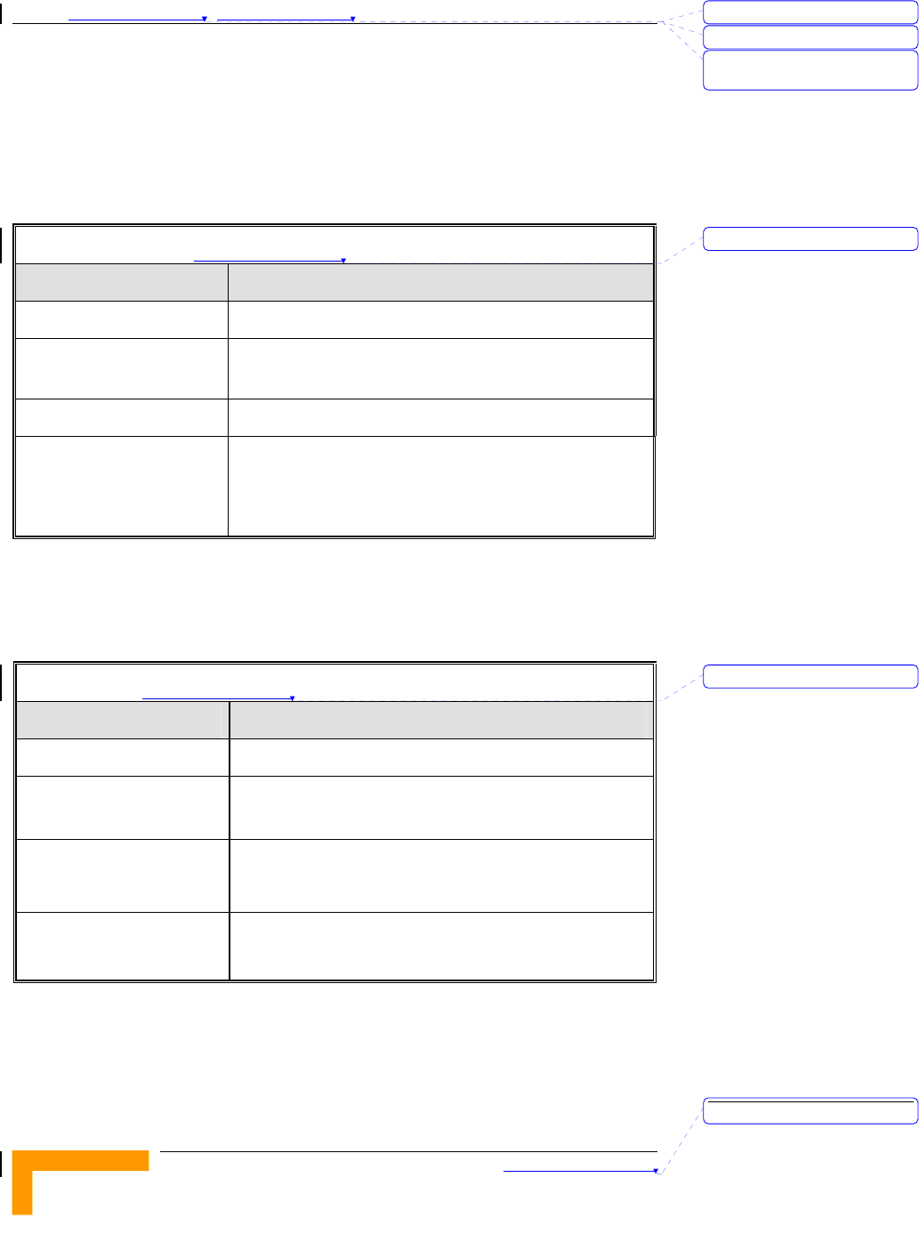
Table 錯誤! 尚未定義樣式。-1: Radio Specifications
Item Description
Frequency 2400-2483.5 MHz
Wireless LAN Standards Compliant with IEEE 802.11b and IEEE 802.11g
(WI-FI certified)
Output Power 10, 12, 15, 17 dBm
Data Rates IEEE 802.11g mode: 54M, 48M, 36M, 24M, 18M,
12M, 6M with auto fallback in.
IEEE 802.11b mode: 11M, 5.5M, 2M, 1M with
auto fallback in.
Regulatory Standards Compliance
Table 錯誤! 尚未定義樣式。-2: Regulatory Standards Compliance
Type Standard
EMC ETS EN 301 489-17
Safety EN 60950 (CE)
IEC 60 950 US/C UL
Radio
ETSI 300 328
FCC Part 15
Immunity EN 55024:1998
刪除: 3
刪除: 3
刪除: Operation and
Administration
刪除: 1
刪除: 1
刪除: Product Description
錯誤! 尚未定義樣式。
Wireless Networking Gateway System Manual
1-7
Environmental
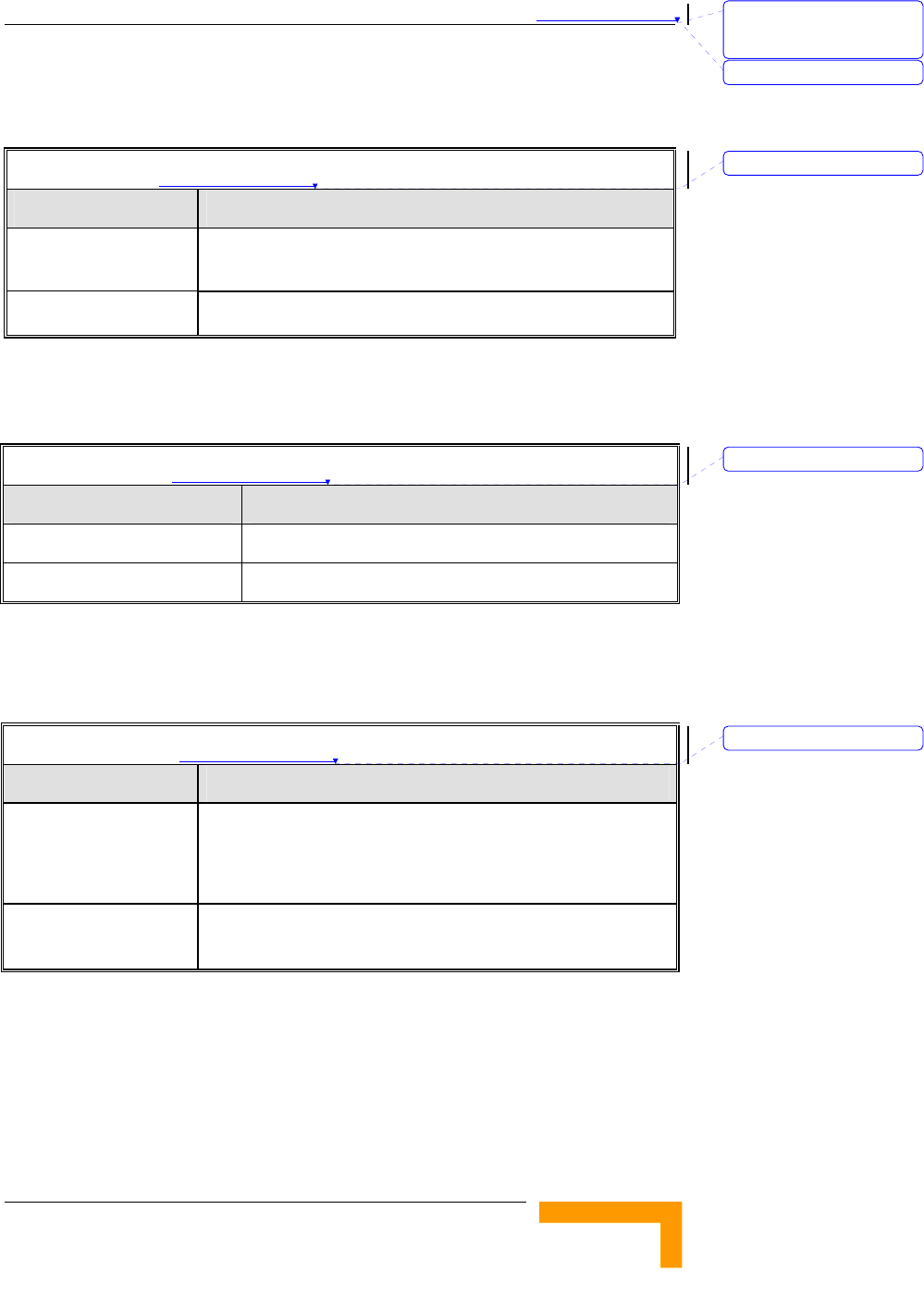
Table 錯誤! 尚未定義樣式。-3: Environmental Specifications
Item Details
Operating
temperature
0 o C to 40 o C
Operating humidity 5%-95% non condensing
Mechanical
Table 錯誤! 尚未定義樣式。-4: Mechanical Specifications
Item Details
Dimensions (W x H x D) 190.5 x 26.2 x 111 mm
Weight 0.62 kg
Electrical
Table 錯誤! 尚未定義樣式。-5: Electrical Specifications
Item Details
Power Transformer 100-240 VAC, 50-60 Hz, 2A max.
Supplies 5 VDC (for the Wireless Networking Gateway
IDU) and 55 VDC (for the ODU via the RADIO connector)
Power Consumption Wireless Networking Gateway IDU (5 VDC): 10W max
ODU (55 VDC): 50W max.
刪除: Set TCP/IP Protocol
for Working with NAT
Router
刪除: Wizard
刪除: 1
刪除: 1
刪除: 1

Chapter 錯誤! 尚未定義樣式。 - 錯誤! 尚未定義樣式。
錯誤! 尚未定義樣式。
1-8
This page is intentionally left blank.
刪除: 3
刪除: 3
刪除: Operation and
Administration
刪除: Product Description

2
2
C
Ch
ha
ap
pt
te
er
r
2
2
-
-
Installation
In this Chapter:
Installation Requirements, page 2-2
Panels Layout and Components, page 2-3
Installation, page 2-6

Chapter 錯誤! 尚未定義樣式。 - 錯誤! 尚未定義樣式。
錯誤! 尚未定義樣式。
2-2
Installation Requirements
Packing List
Wireless Networking Gateway IDU
Antenna
Wall mounting kit
Power Transformer
Mains power cord
Additional Installation Requirements
Ethernet cable(s) for connecting to the end-user’s data equipment.
Mains plug adapter or termination plug (if the power plug on the
supplied AC power cord does not fit local power outlets).
Portable PC with an Ethernet card and an Ethernet cable for
configuring the Wireless Networking Gateway IDU parameters using
a web browser, and for configuring the SU-ODU parameters using
Telnet.
Other installation tools and materials (a drill for wall-mounting the
unit, means for securing cables to walls, etc.)
刪除: 3
刪除: 3
刪除: Operation and
Administration
刪除: Installation
錯誤! 尚未定義樣式。
Wireless Networking Gateway System Manual
2-3
Panels Layout and Components
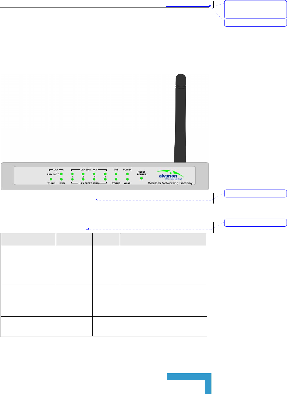
Front Panel
Figure 2-1: Front Panel
Front Panel LEDs
Table 2-1: Front Panel LEDs
LED Function Status Description
POWER Power
Indication On Power is available.
WLAN Wireless LAN
Activity Blinking Sending or receiving data via
wireless LAN
On The USB port is linked.
USB USB Port
Activity Blinking The USB port is sending or
receiving data.
STATUS System
Status Blinking The unit is functioning properly.
刪除: Set TCP/IP Protocol
for Working with NAT
Router
刪除: Wizard
刪除: 2
刪除: 2
Chapter 錯誤! 尚未定義樣式。 - 錯誤! 尚未定義樣式。
錯誤! 尚未定義樣式。
2-4
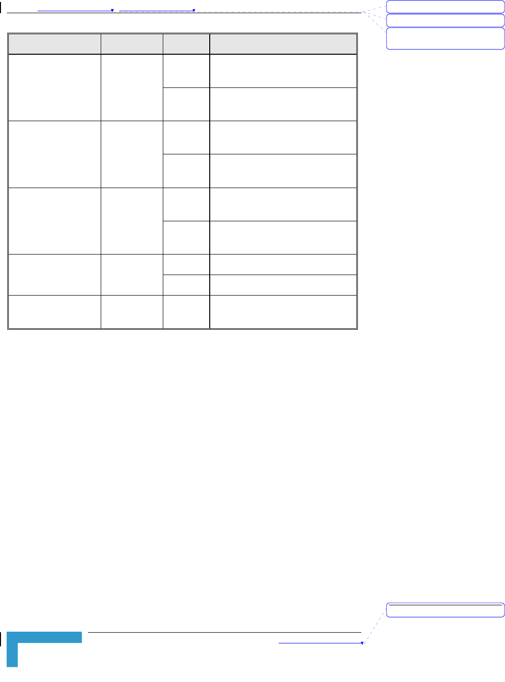
LED Function Status Description
On An active station is connected to
the corresponding LAN port.
LAN LINK/ACT
1~4 LAN Status
Blinking The corresponding LAN port is
sending or receiving data.
On Data rate is 100 Mbps on the
corresponding LAN port.
LAN SPEED 10/100
1~4
LAN Port
Data Rate
Off Data rate is 10 Mbps on the
corresponding LAN port.
On The ODU port is connected to the
ODU.
ODU LINK/ACT ODU Port
Activity
Blinking The ODU port is sending or
receiving data.
On Data rate is 100 Mbps
ODU 10/100
ODU Port
Data Rate Off Data rate is 10 Mbps
ODU WLINK ODU Wireless
Link Status On The ODU is connected with an AU
RESET ROUTER Button
Press momentarily the recessed button to reset the Wireless Networking
Gateway IDU.
Resetting the IDU to Factory Defaults
Press the RESET ROUTER button for 5 seconds at least, until the
STATUS LED flashes 5 times. After releasing the button, the unit will
resume operation with the factory default configuration.
刪除: 3
刪除: 3
刪除: Operation and
Administration
刪除: Installation
錯誤! 尚未定義樣式。
Wireless Networking Gateway System Manual
2-5
Rear Panel Components
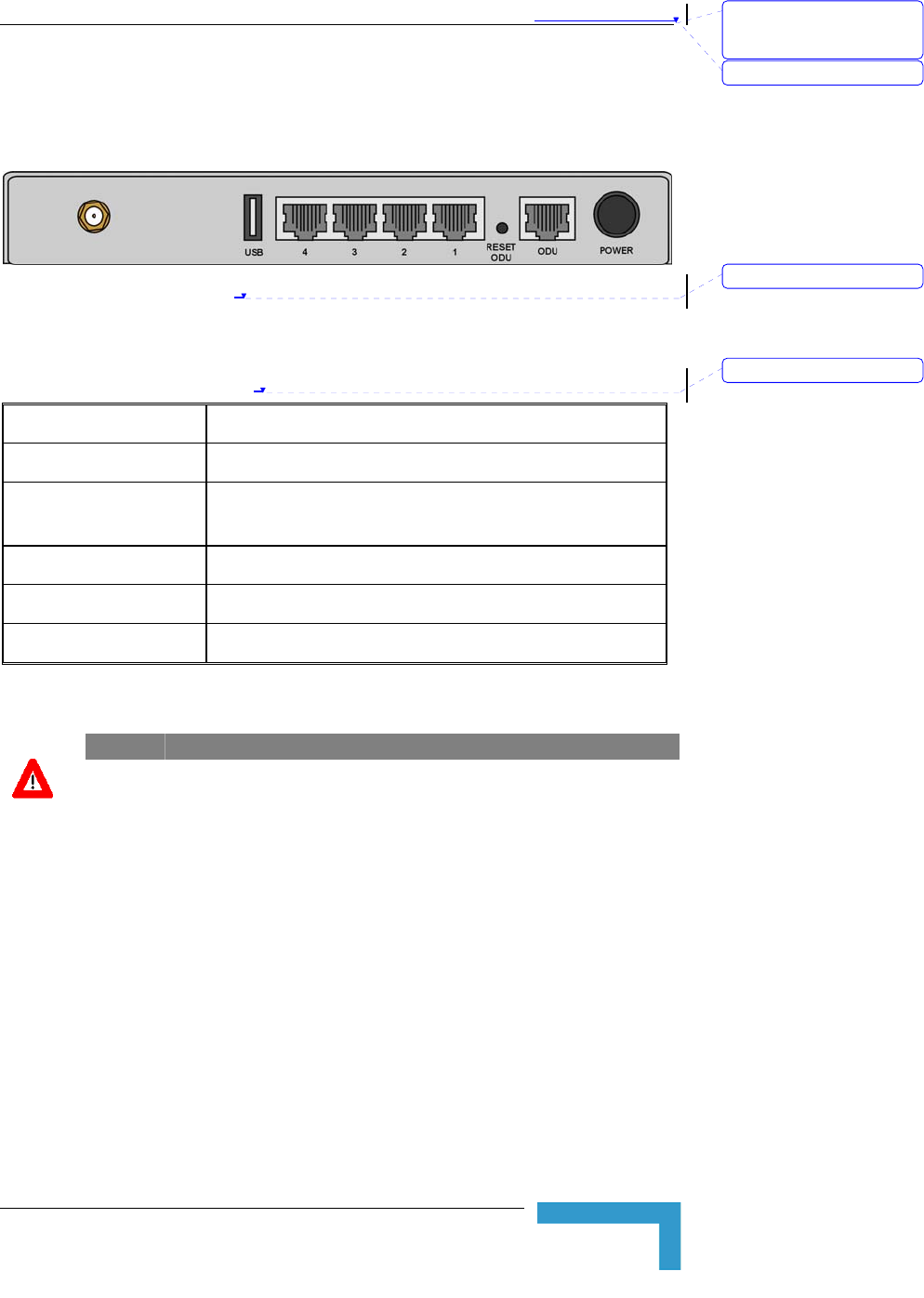
Figure 2-2: Rear Panel (without antenna)
Rear Panel Connectors
Table 2-2: Rear Panel Connectors
Connector Description
POWER DC Power Inlet from Power Transformer
ODU Connection to ODU. Carries Ethernet, Power (55 VDC)
and signaling.
Port 1-4 LAN ports for networked computers and other devices.
USB USB Host Port for a USB printer.
Antenna (not marked) An SMA connector for the WLAN antenna
CAUTION
Do not connect data equipment to the ODU port. The ODU port supplies DC power to
the ODU, and this may harm other equipment connected to it.
RESET ODU Button
Press momentarily the recessed button to reset the ODU.
刪除: Set TCP/IP Protocol
for Working with NAT
Router
刪除: Wizard
刪除: 2
刪除: 2
Chapter 錯誤! 尚未定義樣式。 - 錯誤! 尚未定義樣式。
錯誤! 尚未定義樣式。
2-6
Installation
The unit can be placed on a desktop or a shelf. Alternatively, it may be
wall-mounted. The drilling template included with the unit can be used
to simplify the wall installation process.
For optimal performance, place the Wireless Networking Gateway in the
center of your office (or your home), in a location that is away from any
potential source of interference, such as a metal wall or microwave oven.
This location must be close to a mains outlet and network connections.
1. Assemble an RJ-45 connector with a protective cover on the indoor
end of the IDU-ODU cable. The length of the IDU-ODU cable should
not exceed 100m. Refer to the relevant System Manual for
instructions on preparing the cable.
2. Connect the IDU-ODU cable to the ODU connector located on the
rear panel.
3. Connect the power cord of the transformer to the unit’s POWER
socket, located on the rear panel. Connect the Mains power cord to
the power transformer and to the AC mains.
NOTE
The color codes of the power cable are as follows:
Brown Phase ~
Blue Neutral 0
Yellow/Green Ground
4. Once power is connected, the unit will automatically enter the self-
test phase. When it is in the self-test phase, the STATUS LED will be
lighted ON for about 10 seconds, and then it will blink 3 times,
indicating that the self-test operation has finished. Finally, the
STATUS LED will blink continuously one blink per second,
indicating that the unit is functioning properly.
5. Connect a PC to one of the LAN ports and configure the basic
parameters of the SU-ODU. Align the antenna of the ODU. For more
information refer to the applicable sections of the relevant System
Manual.
6. Use a web browser to configure the parameters of the Wireless
Networking Gateway IDU. For details refer to Chapter 3.
To install the Wireless Networking Gateway IDU:
刪除: 3
刪除: 3
刪除: Operation and
Administration
刪除: Installation

錯誤! 尚未定義樣式。
Wireless Networking Gateway System Manual
2-7
7. Connect the 10/100Base-T Ethernet connectors to the data
equipment. The length of the Ethernet cables should not exceed
100m.
8. If a printer is to be used, connect it to the USB port using a
standard USB cable. To configure the Print Server on your
computer(s), refer to Appendix A - Print Server.
9. Configure the network settings of the computers for proper
operation with the Wireless Networking Gateway. The default IP
address of the Wireless Networking Gateway is 192.168.123.254,
and the default subnet mask is 255.255.255.0. Refer to Appendix B
- TCP/IP Configuration for Windows 95/98.
10. To verify data connectivity, from the end-user’s PC or from a
portable PC connected to the unit, try to connect to the Internet.
11. Verify proper operation using the LED indicators (see Table 2-1on
page 2-3).
刪除: Set TCP/IP Protocol
for Working with NAT
Router
刪除: Wizard
刪除:
T
able 2-1

Chapter 錯誤! 尚未定義樣式。 - 錯誤! 尚未定義樣式。
錯誤! 尚未定義樣式。
2-8
This page is intentionally left blank.
刪除: 3
刪除: 3
刪除: Operation and
Administration
刪除: Installation

3
3
C
Ch
ha
ap
pt
te
er
r
3
3
-
-
Operation and
Administration
In this Chapter
Start-up and Log in on page 3-2
Status on page 3-7
Wizard on page 3-9
Basic Setting on page 3-11
Security Setting on page 3-30
NAT Setting on page 3-41
Advanced Settings on page 3-45
Toolbox on page 3-56

Chapter 錯誤! 尚未定義樣式。 - 錯誤! 尚未定義樣式。
錯誤! 尚未定義樣式。
3-2
Introduction
The Wireless Networking Gateway IDU can be configured using the
following methods:
The Web Configuration Server
An .cfg-file loaded into the unit from the web configuration server or
TFTP.
SNMP
This document describes the configuration using the Web Configuration
Server.
刪除: 3
刪除: 3
刪除: Operation and
Administration
刪除: Operation and
Administration

錯誤! 尚未定義樣式。
Wireless Networking Gateway System Manual
3-3
Accessing the Web Configuration
Server
Follow the steps below to access the Web Configuration Server:
1. Connect the unit to the AC mains.
2. If a DHCP server is being used, the unit may request an IP address
during power up (depending on the .cfg file in the unit).
3. If fixed IP address should be used, proceed as follows:
¾ Unplug the power supply cable from the unit
¾ Press the Reset Router button on the front panel.
¾ Reconnect the power supply cable and keep the Reset Router
button pressed for at least 5 seconds or until the unit
reboots (all LEDs at the front panel will flash)
¾ Release the Reset Router button
After performing this sequence the Wireless Networking Gateway
will be at "factory default" status and have the IP address
192.168.254.253 and subnet mask 255.255.255.0.
When connecting from WAN, make sure that a remote administrator
is enabled (see Security Setting > Miscellaneous Items on page 3-39),
and enter the WAN IP address specified in the System Status
window (see Status on page 3-7).
4. Open a web browser (Internet Explorer or Netscape Communicator).
NOTE
Be sure to disable the proxy on your Web browser or add the IP address of the product
into the exceptions.
5. Enter the IP address of the unit in the Address (IE) or Location
(Netscape) field and click Enter.
6. If the Web Configuration Server is password protected, you will be
prompted to enter your password in order to login to the system.
The default password is .
7. The Web Configuration Server main view appears on the screen.
刪除: Set TCP/IP Protocol
for Working with NAT
Router
刪除: Wizard
Chapter 錯誤! 尚未定義樣式。 - 錯誤! 尚未定義樣式。
錯誤! 尚未定義樣式。
3-4
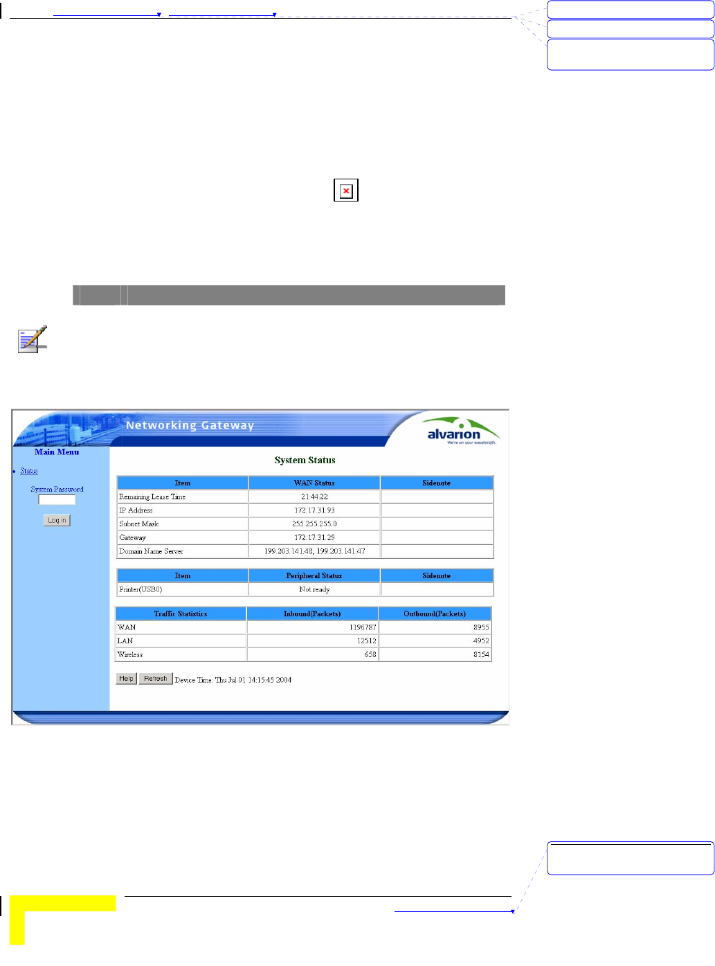
Log in and Log out
After connection is established, the networking gateway web user
interface appears. There are two entry levels: for general users and for
system administrators. The menus and screens vary depending on entry
level. Menus and parameters that are available for Administrator entry
level only, are marked in this manual with
To log in as an administrator, enter the system password (the factory
setting is "private") in the System Password field and click the Log in
button.
NOTE
The default passwords for the two access levels are:
For Administrators: private
For Users: public
Figure 3: Log In Window
After successful Log in, the Networking Gateway Main Window appears.
刪除: 3
刪除: 3
刪除: Operation and
Administration
刪除: Operation and
Administration
錯誤! 尚未定義樣式。
Wireless Networking Gateway System Manual
3-5
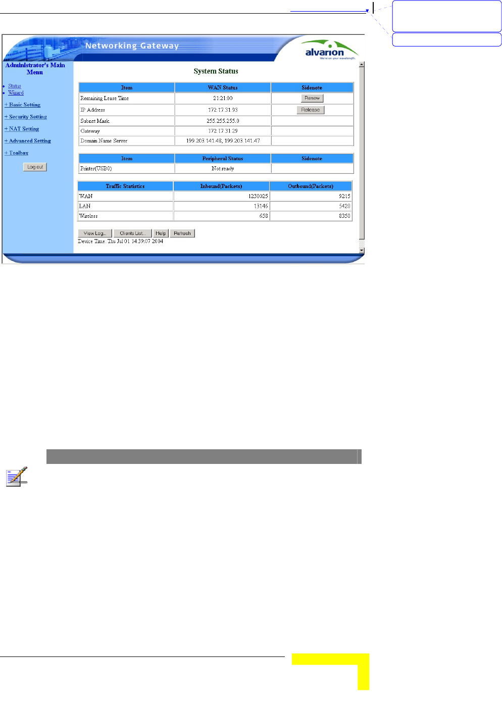
Figure 4: Networking Gateway Main Window
The Menu List
The Web Configuration Server view consists of a number of menu links
(to the left). Clicking on each of them expands the menu node and
displays the selected page with the applicable content (configurable
parameters/options or status information) in the main area.
Control Buttons
Most configuration pages include the some of the following buttons:
NOTE
Some control buttons may be disabled for user entry level (public password)
Help – Displays a help screen for the specific window.
Refresh – Refreshes the displayed information.
Back – Returns to the previous screen.
Undo – Recovers the original settings.
Save – Saves any changes made to the configuration. Most changes
require rebooting the system for them to take effect.
Cancel – Clears unsaved changes to the configuration.
刪除: Set TCP/IP Protocol
for Working with NAT
Router
刪除: Wizard
Chapter 錯誤! 尚未定義樣式。 - 錯誤! 尚未定義樣式。
錯誤! 尚未定義樣式。
3-6
Clients List - TBD
Reboot
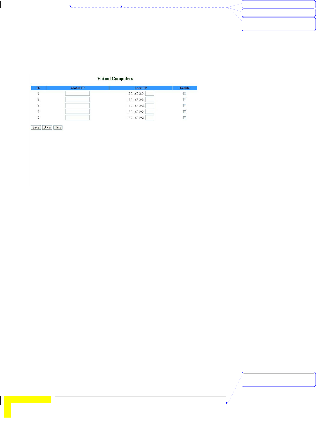
Virtual Computers - Enables to use the original NAT feature, and to
set up the one-to-one mapping of multiple global IP address and
local IP address.
Figure 5: Virtual Computers
¾ Global IP - Enter the global IP address assigned by your ISP.
¾ Local IP - Enter the local IP address of your LAN PC
corresponding to the global IP address.
¾ Enable - Check this item to enable the Virtual Computer
feature.
刪除: 3
刪除: 3
刪除: Operation and
Administration
刪除: Operation and
Administration
錯誤! 尚未定義樣式。
Wireless Networking Gateway System Manual
3-7
Status
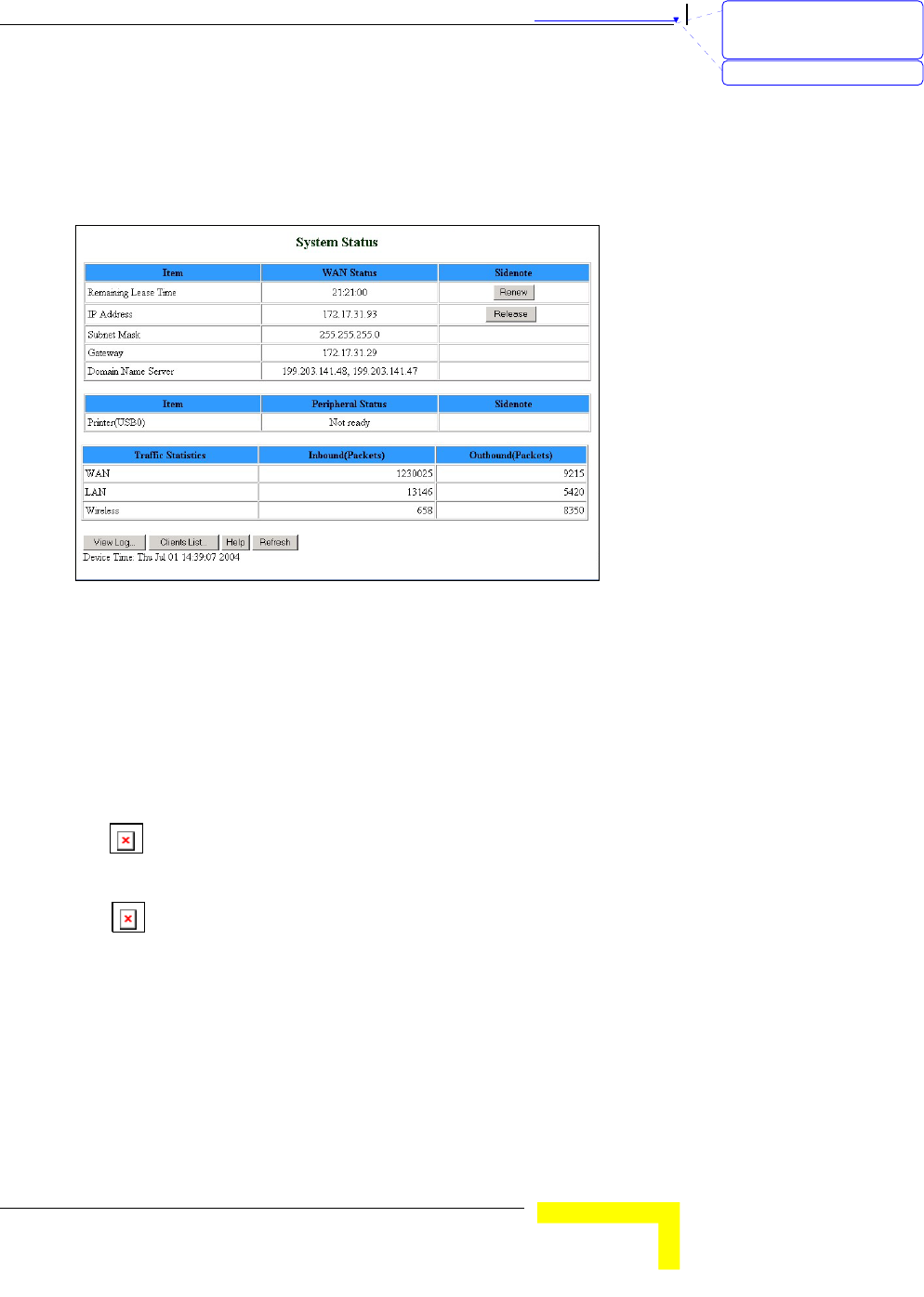
The Status window appears in the main window upon successful log in.
The window can be accessed at any time by clicking on the Status
menu on the menu list.
Figure 6: System Status
The Status window provides information for observing the product's
working status:
Remaining Lease Time - A counter displaying the remaining time (in
hh:mm:ss) in which the user will be allocated the specific IP address.
When the lease time expires, a new IP address will be automatically
allocated, or the lease will be automatically renewed, depending on
the settings.
¾ Renew – Click to reset the Lease Time.
IP Address – The WAN IP address. (The default is 192.168.254.253)
¾ Release – Click to release the IP address.
¾ Disconnect/Connect – When in PPPoE or PPTP mode, click
Disconnect to terminate session, or Connect to initiate a
session.
Subnet Mask – The Subnet mask of the device. (The default is
255.255.255.0)
Gateway – The Gateway IP address.
Domain Name Server – The server's domain name
刪除: Set TCP/IP Protocol
for Working with NAT
Router
刪除: Wizard

Chapter 錯誤! 尚未定義樣式。 - 錯誤! 尚未定義樣式。
錯誤! 尚未定義樣式。
3-8
Peripheral Status: The USB Printer status: Not ready, when no
printer is available. Ready, when a printer is connected and ready to
print.
Traffic Statistics- Enables to monitor inbound and outbound
packets for WAN, LAN and wireless.
In addition, the Status window includes the following control button:
View Log – opens the log file for viewing. See View Log on page 3-56.
刪除: 3
刪除: 3
刪除: Operation and
Administration
刪除: Operation and
Administration
錯誤! 尚未定義樣式。
Wireless Networking Gateway System Manual
3-9
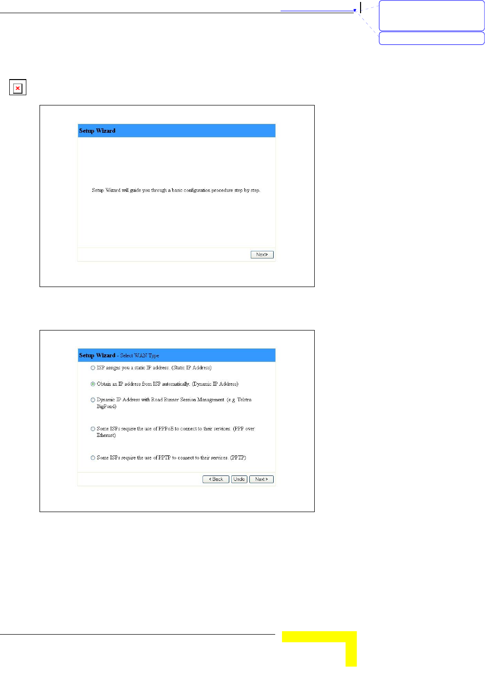
Wizard
The Setup Wizard will guide you through the basic configuration
procedure (recommended for most users).
Figure 7: Setup Wizard
1. Click on Next. The Select WAN Type window appears.
Figure 8: Setup Wizard - Select WAN Type
2. Follow the instructions on screen. Refer to Primary Setup – WAN
Type on page 3-11 for details on each parameter.
You can click Back at any time to return to previous screens and
change your settings.
刪除: Set TCP/IP Protocol
for Working with NAT
Router
刪除: Wizard
Chapter 錯誤! 尚未定義樣式。 - 錯誤! 尚未定義樣式。
錯誤! 尚未定義樣式。
3-10
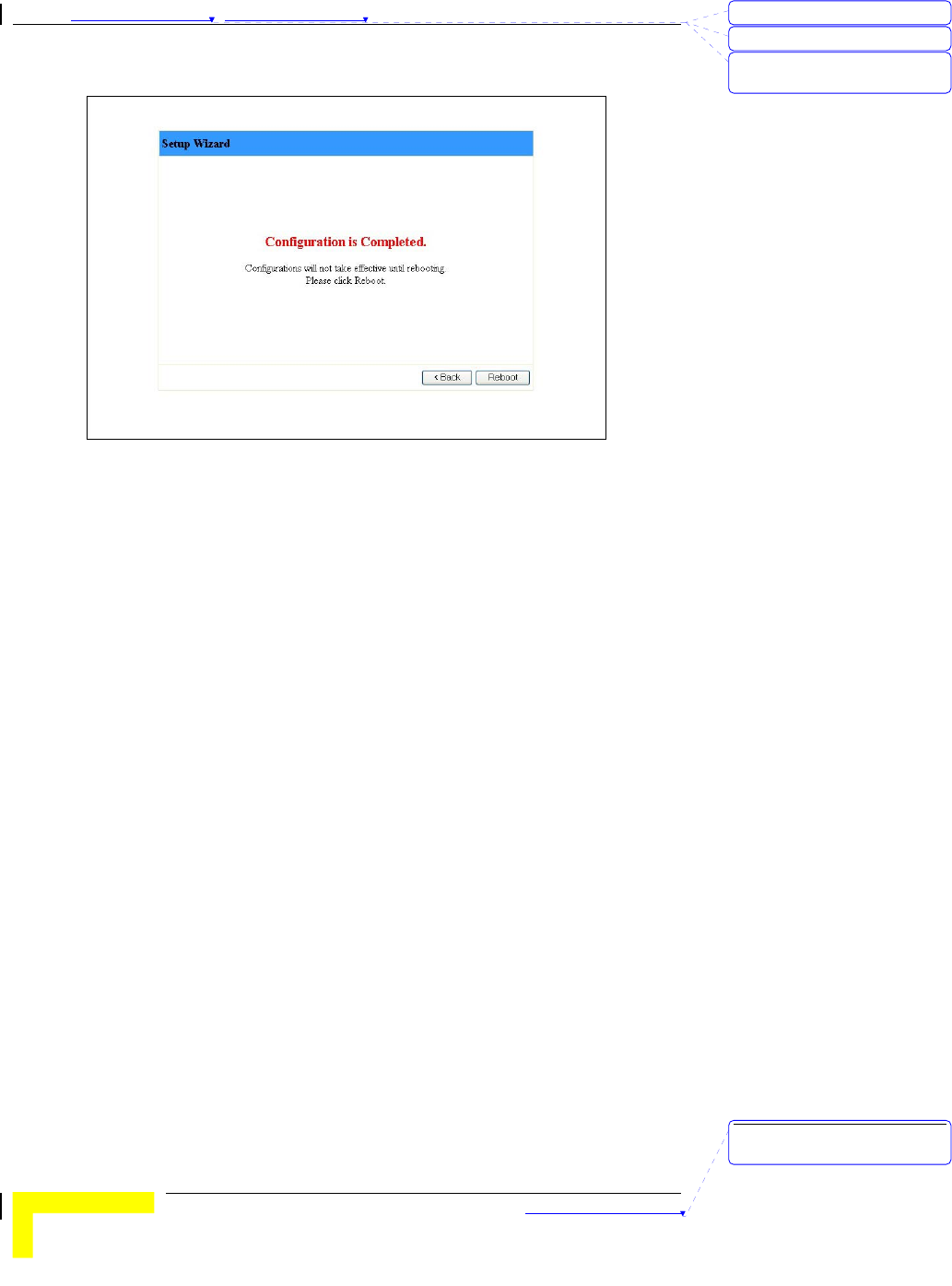
When initial setting is complete, the following window appears:
Figure 9: Setup Wizard - Configuration Completed
3. The configurations will be effective only after rebooting your
computer. Click on Reboot to restart your computer.
For more advance configurations, see details on the specific windows,
below.
刪除: 3
刪除: 3
刪除: Operation and
Administration
刪除: Operation and
Administration
錯誤! 尚未定義樣式。
Wireless Networking Gateway System Manual
3-11
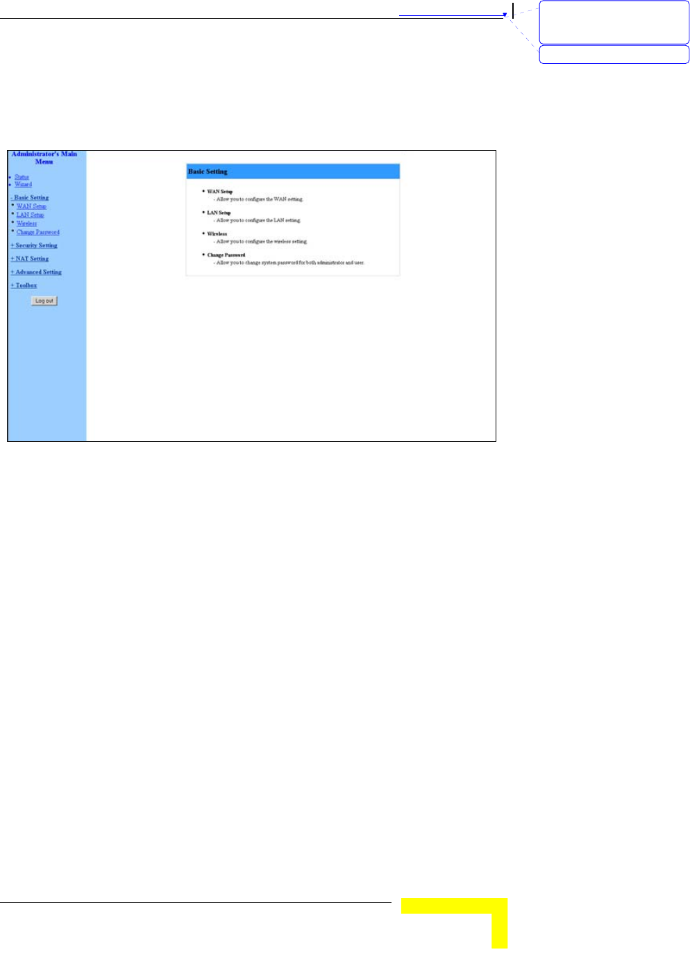
Basic Setting
The Basic Setting window allows you to configure the settings for WAN,
LAN, and Wireless and to change the password.
Figure 10: Basic Setting
WAN Setup
Click on WAN Setup from the Basic Setting menu on the menu list. The
Primary Setup window appears.
刪除: Set TCP/IP Protocol
for Working with NAT
Router
刪除: Wizard
Chapter 錯誤! 尚未定義樣式。 - 錯誤! 尚未定義樣式。
錯誤! 尚未定義樣式。
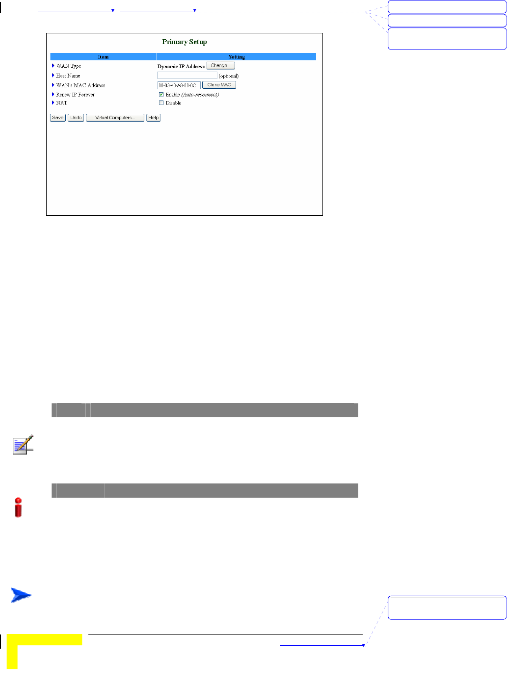
3-12
Figure 11: WAN Setup/Primary Setup
From the WAN Setup window you can:
Set the WAN type – allows you to select the WAN connection type of
your ISP.
Enter the Host Name (optional)
Set WAN's MAC Address
Enable/Disable Renew IP Forever
NAT – Enable/Disable - When disabled, the gateway functions as a
regular router as opposed to a NAT router. This option is available
in the Primary Setup window for all WAN types.
NOTE
The Reboot button is not available at first entry to the Primary Setup window and
appears only after saving your changes.
For client entry level (public password), the parameter fields in all WAN type
screens are disabled (for display only).
IMPORTANT
Changes to the Primary Setup window will take effect only after rebooting the system.
The default WAN type is Dynamic IP Address with Road Runner
Session Management. However, you can change the WAN type as
follows:
To select a different WAN type:
刪除: 3
刪除: 3
刪除: Operation and
Administration
刪除: Operation and
Administration
錯誤! 尚未定義樣式。
Wireless Networking Gateway System Manual
3-13
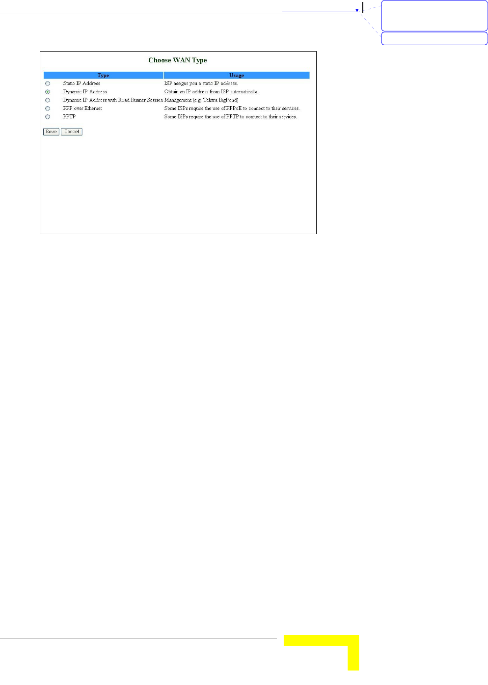
1. Click Change. The Choose WAN Type window opens.
Figure 12: Choose WAN Type
2. Select one of the following types:
¾ Static IP Address: The ISP provides you with a static IP
address.
¾ Dynamic IP Address: Automatically obtain an IP address
from the ISP.
¾ Dynamic IP Address with Road Runner Session Management.
(e.g. Telstra BigPond) (default)
¾ PPP over Ethernet: Some ISPs require the use of PPPoE to
connect to their services.
¾ PPTP: Some ISPs require the use of PPTP to connect to their
services.
For each WAN type selected, a different Primary Setup window appears,
as follows. You can change the WAN type by clicking on Change and
selecting a different WAN type.
刪除: Set TCP/IP Protocol
for Working with NAT
Router
刪除: Wizard
Chapter 錯誤! 尚未定義樣式。 - 錯誤! 尚未定義樣式。
錯誤! 尚未定義樣式。
3-14
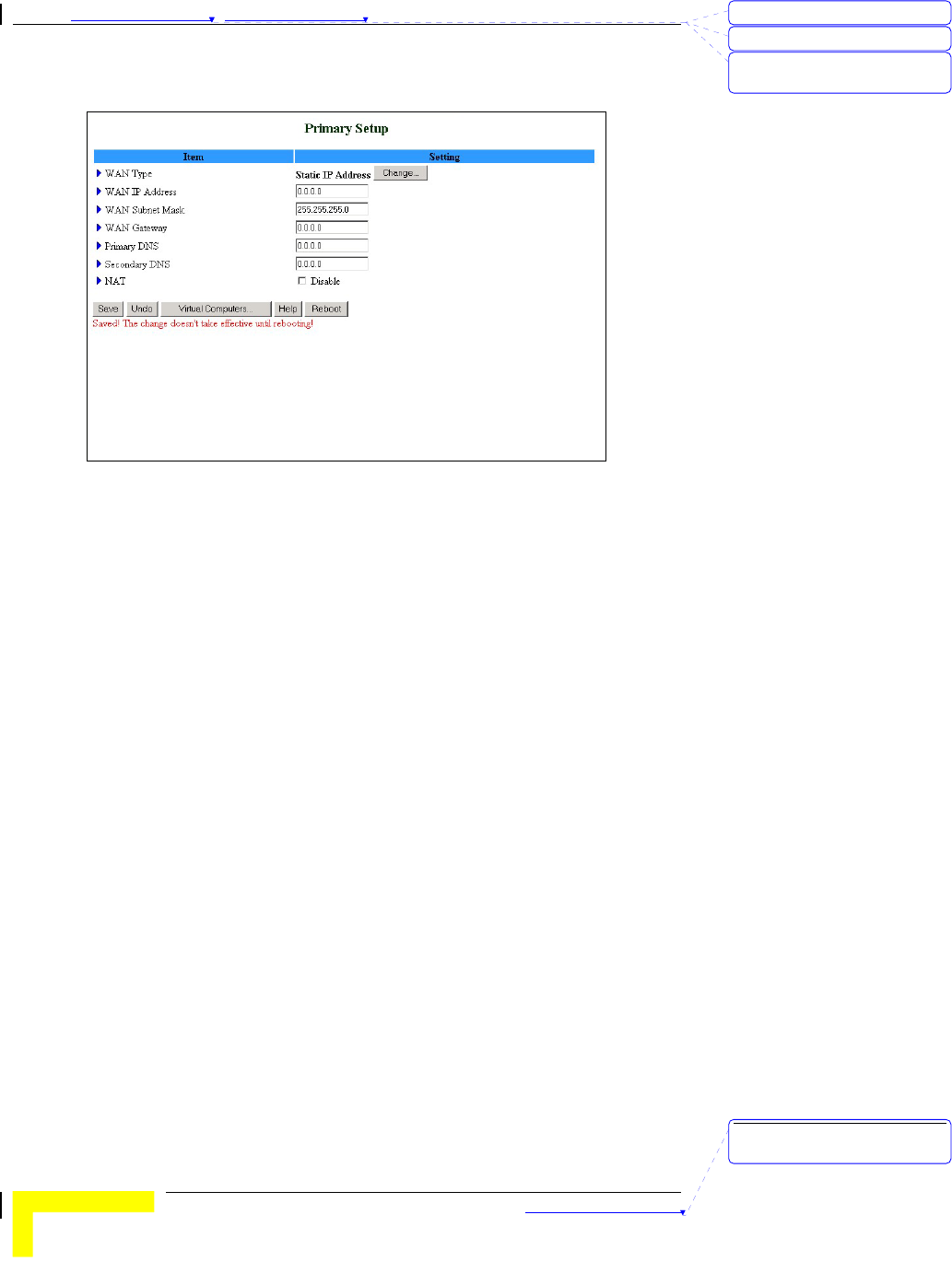
Static IP Address
Figure 13: Primary Setup - Static IP Address
Enter the settings provided by your ISP for WAN IP Address, Subnet
Mask, Gateway, Primary and Secondary DNS.
刪除: 3
刪除: 3
刪除: Operation and
Administration
刪除: Operation and
Administration
錯誤! 尚未定義樣式。
Wireless Networking Gateway System Manual
3-15
Dynamic IP Address
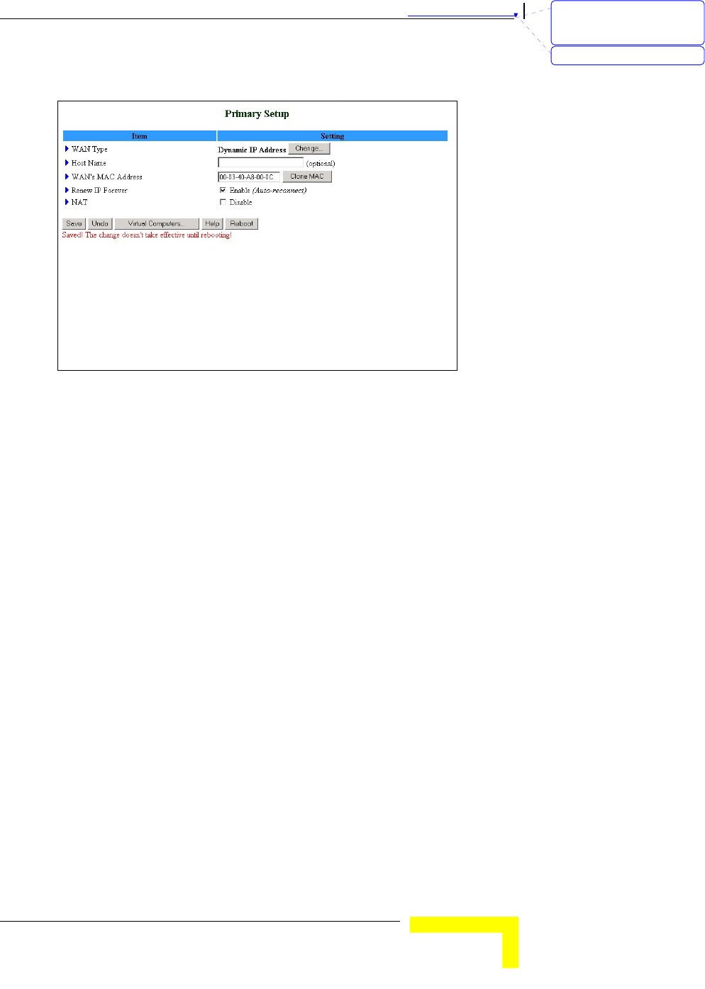
Figure 14: Primary Setup - Dynamic IP Address
Host Name: optional. Required by some ISPs, for example, @Home.
WAN's MAC Address – The gateway's pre-configured MAC Address.
¾ Clone MAC – Click to replace the Gateway's MAC Address
with the PC's MAC Address.
¾ Restore MAC – When Clone MAC is activated, the button
changes to Restore MAC, to enable to restore the unit's pre-
configured MAC Address.
Renew IP Forever: When enabled, this feature will automatically
renew your IP address when the lease time expires, even if the
system is idle.
刪除: Set TCP/IP Protocol
for Working with NAT
Router
刪除: Wizard
Chapter 錯誤! 尚未定義樣式。 - 錯誤! 尚未定義樣式。
錯誤! 尚未定義樣式。
3-16
Dynamic IP Address with Road Runner Session
Management
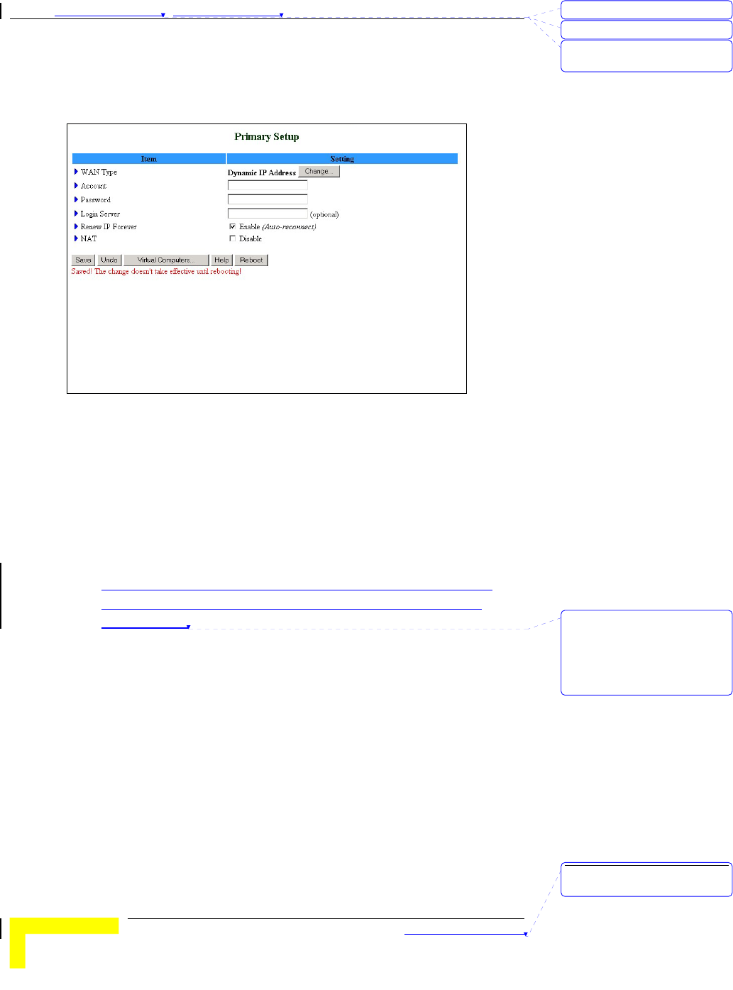
Figure 15: Primary Setup - Dynamic IP Address with Road Runner Session
Management
Account – The account provided by your ISP.
Password – The password provided by your ISP. If you do not want
to change the password, leave empty.
Login Server – The Login Server (optional). Leave empty if you want
the default server.
Renew IP Forever: When enabled, this feature will automatically
renew your IP address when the lease time expires, even if the
system is idle.
刪除: 3
刪除: 3
刪除: Operation and
Administration
刪除: Renew IP Forever:
When enabled, this feature
will automatically renew
your IP address when the
lease time expires, even if
the system is idle.
刪除: Operation and
Administration
錯誤! 尚未定義樣式。
Wireless Networking Gateway System Manual
3-17
PPP over Ethernet
Some ISPs require the use of PPPoE to connect to their services. If this
is the case, click Change to select PPPoE as your WAN type. The
Primary Setup window display changes to reflect the parameters for
PPPoE.
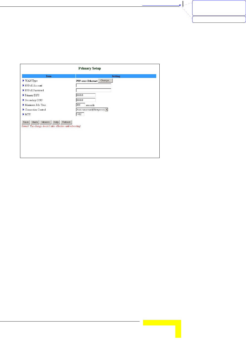
Figure 16: Primary Setup - PPPoE
PPPoE Account – The account assigned to you by your ISP.
PPPoE Password: the password assigned to you by your ISP. This
field appears blank. If you don't want to change the password, leave
it empty.
Primary DNS – The DNS provided by your ISP. To use a specific DNS,
enter a specific address (optional).
Secondary DNS – The backup DNS provided by your ISP. (optional)
Maximum Idle Time - The amount of time of inactivity before
disconnecting your PPPoE session. To disable this feature, set this
parameter to 0 seconds, or enable Auto-reconnect.
Connection Control – Authentication for IP allocation. Select one of
the following options:
¾ Connect-on-demand – An IP address is automatically
allocated whenever the user attempts to make a connection.
¾ Auto reconnect(Always-on) – The system automatically
connects to the ISP after restart or after connection is
dropped.
刪除: Set TCP/IP Protocol
for Working with NAT
Router
刪除: Wizard

Chapter 錯誤! 尚未定義樣式。 - 錯誤! 尚未定義樣式。
錯誤! 尚未定義樣式。
3-18
¾ Manually – The user manually performs the connection.
Maximum Transmission Unit (MTU) - Most ISPs provide an MTU
value to users. The most common MTU value is 1492 bytes.
More >> - Click to display the following parameters:
¾ PPPoE Service Name (optional) - Directs to a PPPoE server.
¾ Assigned IP Address (optional) – Directs to a specific server.
刪除: 3
刪除: 3
刪除: Operation and
Administration
刪除: Operation and
Administration
錯誤! 尚未定義樣式。
Wireless Networking Gateway System Manual
3-19
PPTP
Some ISPs require the use of PPTP to connect to their services.
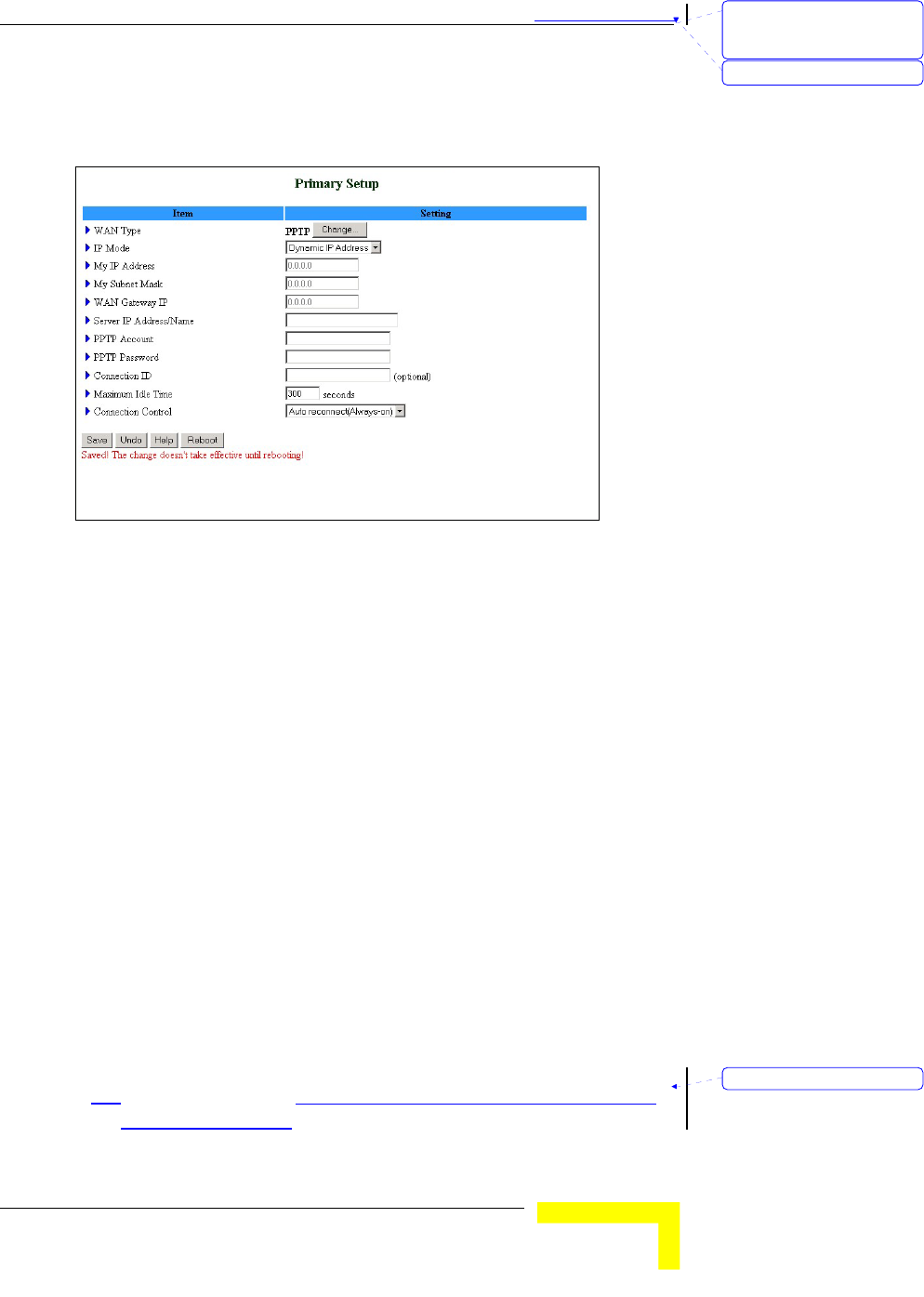
Figure 17: Primary Setup - PPTP
IP Mode – select one of the following options:
¾ Dynamic IP Address (this is the default setting)
¾ Static IP Address
My IP Address – The private IP address assigned by your ISP.
My Subnet Mask - The private subnet mask assigned by your ISP.
WAN Gateway IP – The WAN Gateway IP address.
Server IP Address/Name: the IP address/Name of the PPTP server.
PPTP Account – The account assigned by your ISP.
PPTP Password - The password assigned by your ISP. If you do not
want to change the password, leave this field empty.
Connection ID - Enter the connection ID if your ISP requires it
(optional).
Maximum Idle Time - The amount of time of inactivity before
disconnecting your PPTP session. To disable this feature, set this
parameter to 0 seconds, or enable Auto-reconnect.
Connection Control – Authentication for IP allocation. Select one of
the following options:
刪除: Set TCP/IP Protocol
for Working with NAT
Router
刪除: Wizard
格式化: 項目符號及編號
Chapter 錯誤! 尚未定義樣式。 - 錯誤! 尚未定義樣式。
錯誤! 尚未定義樣式。
3-20
¾ Connect-on-demand – An IP address is automatically
allocated whenever the user attempts to make a connection.
¾ Auto reconnect(Always-on) – The system automatically
connects to the ISP after restart or after connection is
dropped.
¾ Manually – The user manually performs the connection.
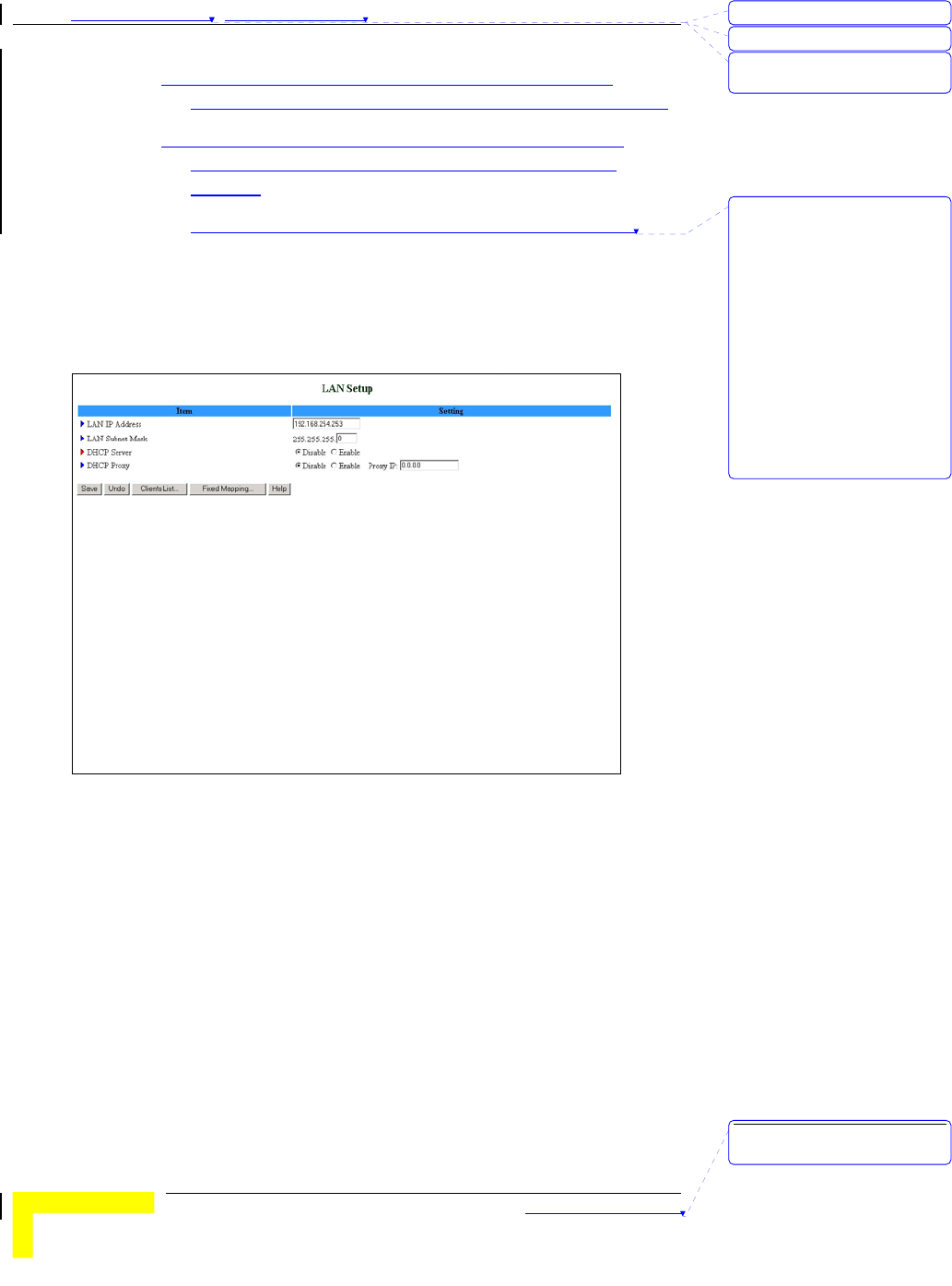
LAN Setup
Select Basic Setting > LAN Setup submenu on the menu list. The LAN
Setup window opens.
Figure 18: LAN Setup
Enter the following parameters:
LAN IP Address – Sets the local IP address of the device. The users
on your network must use this LAN IP address as their default
gateway. You can change it as necessary.
LAN Subnet Mask – Sets the subnet mask to the LAN IP address.
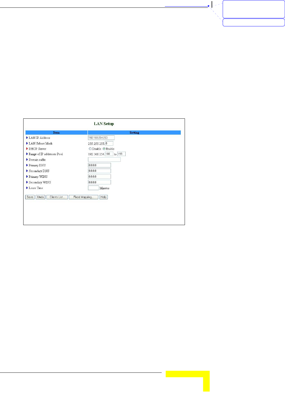
DHCP Server – Enable/Disable to turn off this service. When
enabled, the LAN Setup window display changes (indicated by the
red icon), and the following parameters are displayed (see Figure 19):
¾ Range of IP addresses Pool – Specify the starting and ending
address for DHCP clients.
¾ Domain suffix – Specify the domain suffix for DHCP clients.
刪除: 3
刪除: 3
刪除: Operation and
Administration
刪除: Authentication for IP
allocation. Select one of the
following options:
<#>Connect-on-demand –
An IP address is
automatically allocated
whenever the user attempts
to make a connection.
<#>Auto reconnect(Always-
on) – The system
automatically connects to
the ISP after restart or after
connection is dropped.
Manually – The user
manually performs the
connection.
刪除: Operation and
Administration
錯誤! 尚未定義樣式。
Wireless Networking Gateway System Manual
3-21
¾ Primary DNS – Specify the primary DNS for DHCP clients.
¾ Secondary DNS – Specify the secondary DNS for DHCP
clients.
¾ Primary WINS – Specify the primary WINS address for DHCP
clients.
¾ Secondary WINS – Specify the secondary WINS address for
DHCP clients.
¾ Lease Time – The time set (in minutes) for IP allocation.
DHCP Proxy – This parameter is available only when DHCP Server is
disabled.
Figure 19: LAN Setup - DHCP Enabled
In addition, the LAN Setup window includes the following control
buttons:
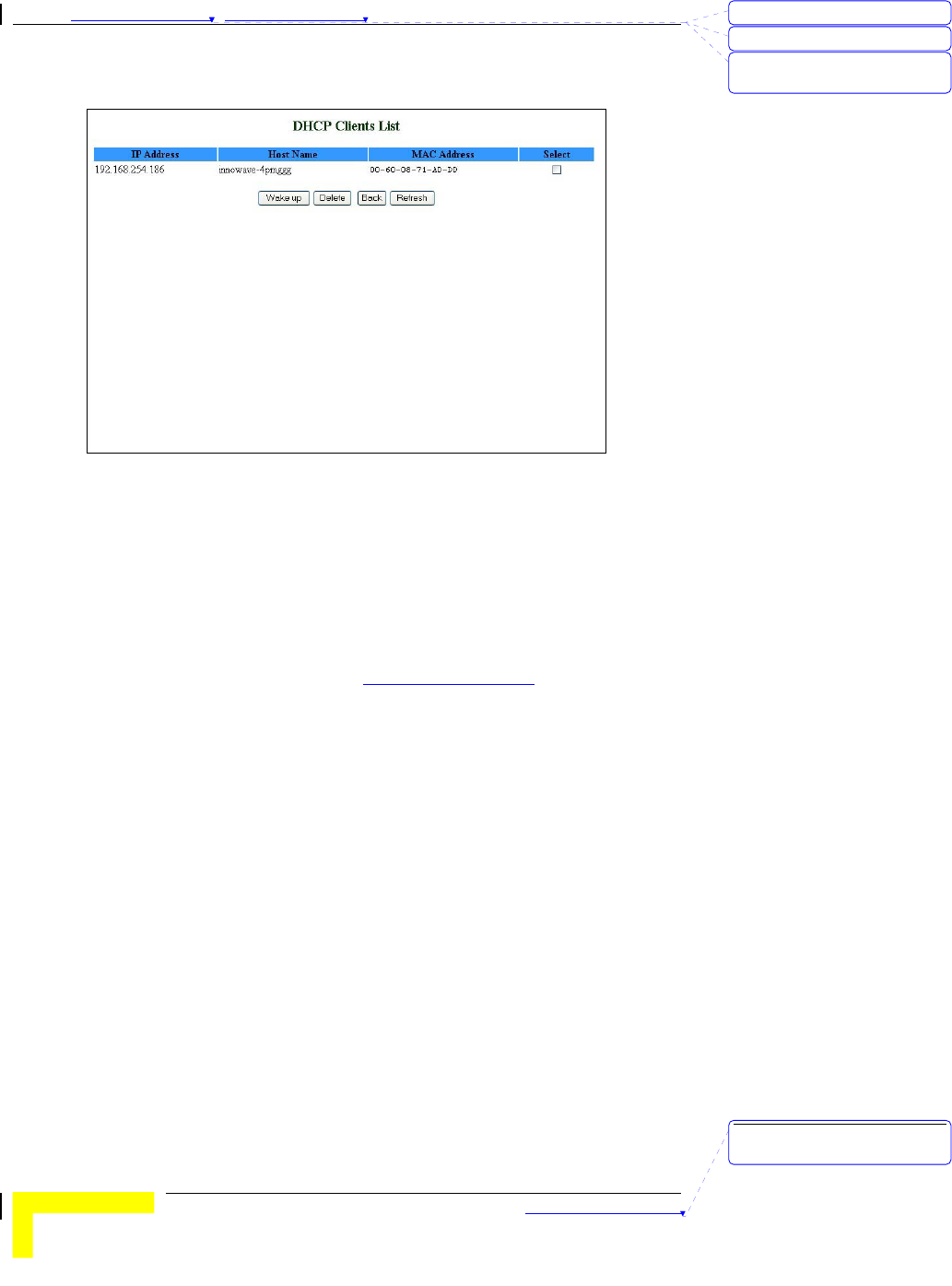
Clients List – Opens a list of the current mapping of the IP and MAC
address for each DHCP client.
刪除: Set TCP/IP Protocol
for Working with NAT
Router
刪除: Wizard
Chapter 錯誤! 尚未定義樣式。 - 錯誤! 尚未定義樣式。
錯誤! 尚未定義樣式。
3-22
Figure 20: DHCP Clients List
From the DHCP Clients List window you can:
¾ Wake up – TBD
¾ Delete – Delete the selected clients.
¾ Fixed Mapping – Opens the MAC Address Control window for
assigning a specific IP address to the specified MAC address
for DHCP clients (see MAC Address Control on page 3-25 for
further details).
刪除: 3
刪除: 3
刪除: Operation and
Administration
刪除: Operation and
Administration
錯誤! 尚未定義樣式。
Wireless Networking Gateway System Manual
3-23
Figure 21: MAC Address Control
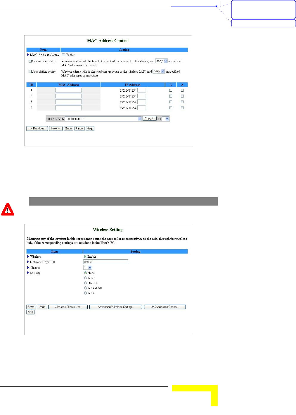
Wireless Setting
Wireless settings allow you to set the wireless configuration items.
CAUTION
Changing any of the parameters may cause loss of wireless link connectivity to the unit
if the settings do not match the settings on the User's PC.
Figure 22: Wireless Setting
Wireless – Enable/Disable – Check the Enable box to enable this
service. The default setting is "Enable".
刪除: Set TCP/IP Protocol
for Working with NAT
Router
刪除: Wizard

Chapter 錯誤! 尚未定義樣式。 - 錯誤! 尚未定義樣式。
錯誤! 尚未定義樣式。
3-24
Network ID (SSID): Network ID is used for identifying the Wireless
LAN (WLAN). Client stations can roam freely over this product and
other Access Points that have the same Network ID. (The factory
setting is "default".)
Channel: The radio channel number. The permissible channels
depend on the Regulatory Domain.
Security: Select the data privacy algorithm you want to protect your
data when being transferred from one station to another. The
available security protocols are:
¾ None – No encryption is applied. (default)
¾ WEP (Wired Equivalent Privacy) – Encrypts frames
transmitted through a wireless module using a pre-entered
WEP key. You can configure 4 key sets and select one to
apply as follows:
WEP 64 bit - 10 hexadecimal digits
WEP 126 bit – 26 hexadecimal digits
WEP 258 bit – 58 hexadecimal digits
¾ 802.1x – When enabled, the wireless user must be
authenticated before it is allowed to use the network services.
One implementation of 802.1x (the most common one) is
through a RADIUS server on your LAN, containing an
authentication database.
Encryption Key Length – Select either 64 or 128 bits for
the encryption key.
RADIUS Server IP – The 802.1x server's IP address.
RADIUS Port – The 802.1x server's service port.
RADIUS Shared Key – Key value shared by the RADIUS
server and the networking gateway. The key value is
consistent with the one in the RADIUS server.
¾ WPA-PSK – Accepts WPA clients only. Manually enter a pre-
share key (encryption key) as follows:
Pre-share key mode: ASCII or HEX can be selected.
Pre share key: 32 ASCII characters or 64 hexadecimal
digits pre-share key (encryption key).
刪除: 3
刪除: 3
刪除: Operation and
Administration
刪除: Operation and
Administration
錯誤! 尚未定義樣式。
Wireless Networking Gateway System Manual
3-25
¾ WPA (Wi-Fi Protected Access) – improves data protection and
implements access control to Wireless LAN systems. Frames
transmitted through a wireless module are encrypted using a
Pre-share key (PSK) or a key received from the RADIUS
server.
RADIUS Server IP – The 802.1x server's IP address.
RADIUS Port – The 802.1x server's service port.
RADIUS Shared Key – Key value shared by the RADIUS
server and the networking gateway. The key value is
consistent with the one in the RADIUS server.
IMPORTANT
If you enable the 802.1x or WPA feature, you must have a RADIUS server available.
Advanced Wireless Setting
Clicking the Advanced Wireless Setting button that appears in the
Wireless Setting window opens the Advanced Wireless Setting window.
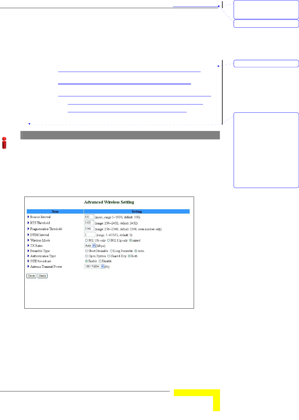
Figure 23: Advanced Wireless Setting
Enter the following parameters:
Beacon Interval – Specify the intervals (in milliseconds) between
beacons (the range is 1~1000 milliseconds, the default is 100
milliseconds).
刪除: Set TCP/IP Protocol
for Working with NAT
Router
刪除: Wizard
格式化: 項目符號及編號
刪除: <#>RADIUS Server
IP – The 802.1x server's
IP address.
<#>RADIUS Port – The
802.1x server's service
port.
<#>RADIUS Shared Key –
Key value shared by the
RADIUS server and the
networking gateway. The
key value is consistent
with the one in the
RADIUS server.
Chapter 錯誤! 尚未定義樣式。 - 錯誤! 尚未定義樣式。
錯誤! 尚未定義樣式。
3-26
RTS Threshold – Specify the packet size above which a Request To
Send will be performed (the range is 256~2432, the default is 2432).
Fragmentation Threshold – Specify the packet size above which
fragmentation will be performed (the range is 256~2346 even
numbers only, the default is 2346).
DTIM Interval – [TBD]
Wireless Mode – The wireless mode supported: 802.11b, 802.11g, or
both.
TX Rates – Select the transmission rate from the dropdown list.
Preamble Type – Select short/long or automatic preamble to be
assigned to each packet.
Authentication Type – [TBD]
SSID Broadcast – [TBD what is SSID?] Enable/Disable broadcasting
the network's ID.
Antenna Transmit Power – Select the antenna's transmission power
from the dropdown list.
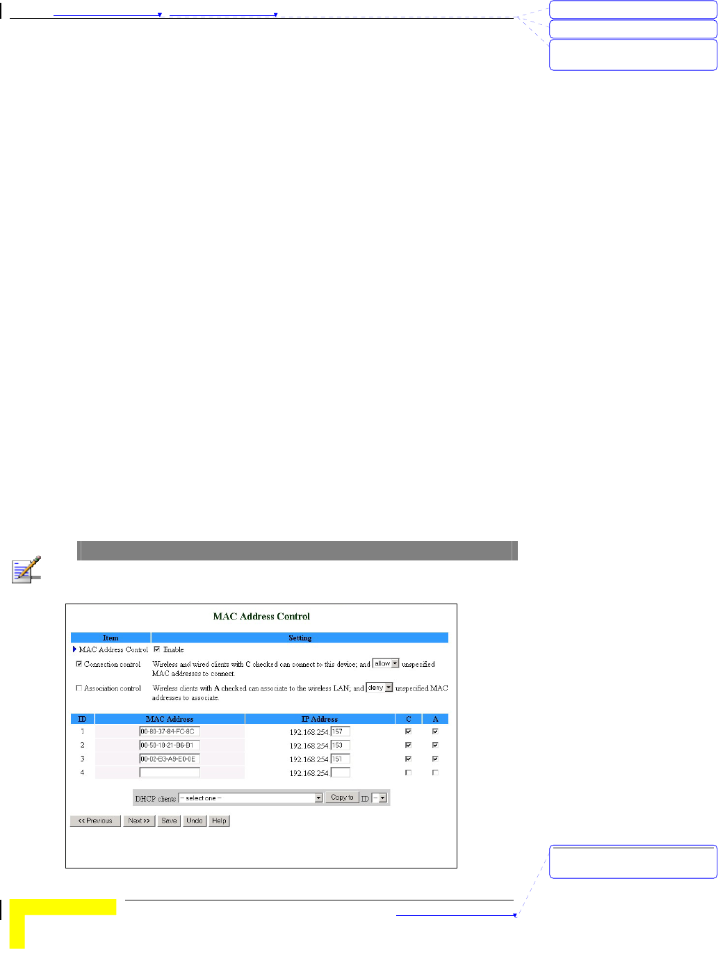
MAC Address Control
MAC Address Control allows you to assign different access rights for
different users and to assign a fixed IP address to a specific MAC
address.
NOTE
All the settings in this page will take effect only when MAC Address Control is set to
"Enable".
刪除: 3
刪除: 3
刪除: Operation and
Administration
刪除: Operation and
Administration

錯誤! 尚未定義樣式。
Wireless Networking Gateway System Manual
3-27
MAC Address Control – Check "Enable" to enable the MAC Address
Control feature.
Connection control – Check the "Connection control" check box to
enable controlling which wired and wireless clients can connect to
this device. If a client is denied the connection to this device, he will
not be able to access the Internet either. Select allow/deny to allow
or deny clients whose MAC addresses are not in the "Control table"
(see below) to connect to this device. ("deny" is the default setting.)
A wired client who is allowed to connect to the device has full access
to the Internet and to network resources. When denied the
connection to the device, he can communicate with other clients on
the wired LAN, but cannot connect to the Internet, use the Print
Server function, communicate with clients on the wireless LAN, or
use the Web configuration.
Association control – "Association" refers to the exchanging of
information between wireless clients and the device to establish a
link between them. A wireless client is able to transmit and receive
data to the device only after successful association. Check
"Association control" check box to control which wireless clients can
associate to the wireless LAN. If a client is denied the association to
the wireless LAN, he will not be able to send or receive any data via
this device. Select allow/deny to allow or deny clients whose MAC
addresses are not in the "Control table" to associate to the wireless
LAN.
A wireless client who is allowed both to associate to the wireless
LAN and to connect to the device has full access to the Internet and
to network resources.
When allowed to associate to the wireless LAN, but denied to
connect to the device, he can communicate with other clients on the
LAN (wired and wireless), but cannot connect to the Internet, use
the Print Server function, or use the Web configuration.
When denied to associate to the wireless LAN, the client cannot
communicate with other clients on the LAN (wired or wireless),
connect to the internet, use the Print Server function, or use the
Web configuration. [TBD – provide a summary table]
NOTE
Association control does not affect wired clients.
刪除: Set TCP/IP Protocol
for Working with NAT
Router
刪除: Wizard
Chapter 錯誤! 尚未定義樣式。 - 錯誤! 尚未定義樣式。
錯誤! 尚未定義樣式。
3-28
Control table - Each row in the control table indicates the MAC
address and the mapped IP address of a single client. The table
shows the following parameters:
¾ MAC Address – The MAC address of a specific client.
¾ IP Address – The expected IP address of the corresponding
client. Leave empty if you do not want to specify an IP
address for the corresponding client.
¾ C - When "Connection control" is checked, checking "C" will
allow/deny (depending on the connection control setting) the
corresponding client to connect to this device.
¾ A - When "Association control" is checked, checking "A" will
allow/deny (depending on the association control setting) the
corresponding client to associate to the wireless LAN.
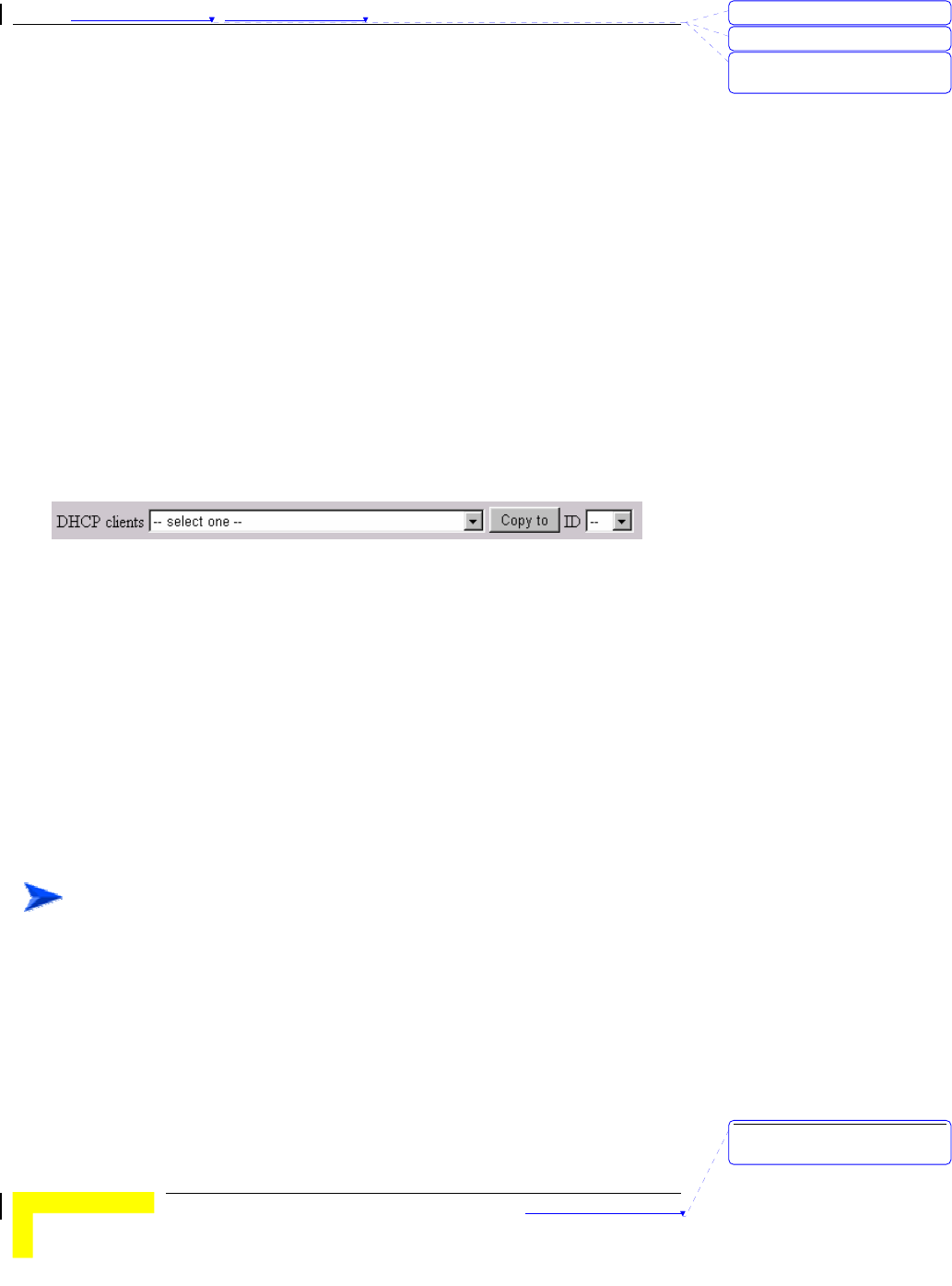
DHCP clients Combo box – Facilitates the process of entering the
MAC address.
Select a specific client in the "DHCP clients" Combo box and click on
Copy to to copy the MAC address of the selected client to the
selected ID in the "ID" Combo box
The control table is divided into several pages. Use the << Previous
page and Next Page >> buttons to jump to a different page.
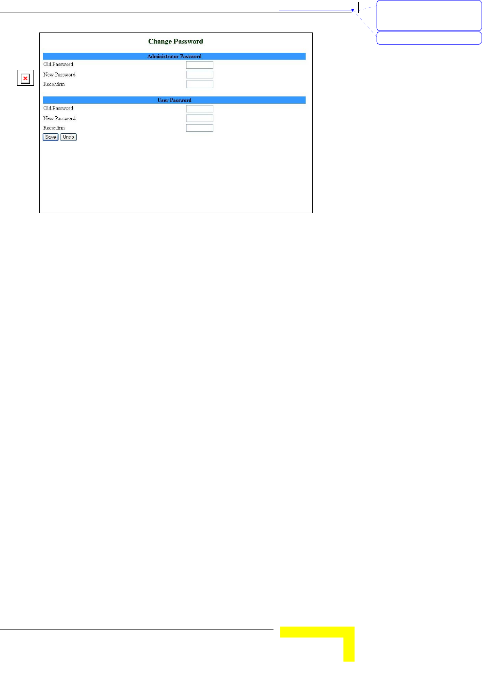
Change Password
The Change Password window allows you to change the system
password. For security reasons, it is strongly recommended that you do
so.
1. Select Basic Setting > Change Password submenu on the menu list.
The Change Password window opens.
To access change password:
刪除: 3
刪除: 3
刪除: Operation and
Administration
刪除: Operation and
Administration
錯誤! 尚未定義樣式。
Wireless Networking Gateway System Manual
3-29
Figure 24: Change Password
2. Type in the old password in the Old Password box.
3. Type in the new password in the New Password box.
4. Re-type the new password in the Reconfirm box.
5. Click Save to save the new password(s).
Follow this procedure for the Administrator Password level, for the User
Password level, or for both password levels.
刪除: Set TCP/IP Protocol
for Working with NAT
Router
刪除: Wizard
Chapter 錯誤! 尚未定義樣式。 - 錯誤! 尚未定義樣式。
錯誤! 尚未定義樣式。
3-30
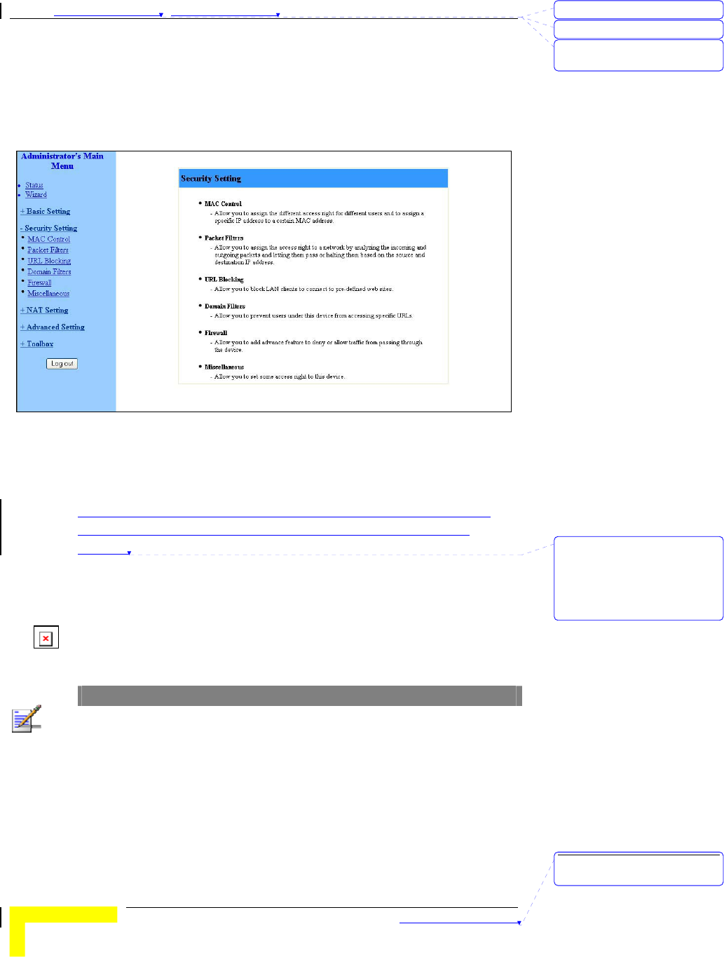
Security Setting
Click on the Security Setting menu on the menu list to display the
submenus and the Security Setting window.
Figure 25: Security Setting Window
MAC Control
MAC Address Control allows you to assign different access rights for
different users and to assign a fixed IP address to a specific MAC
address. See MAC Address Control on page 3-26.
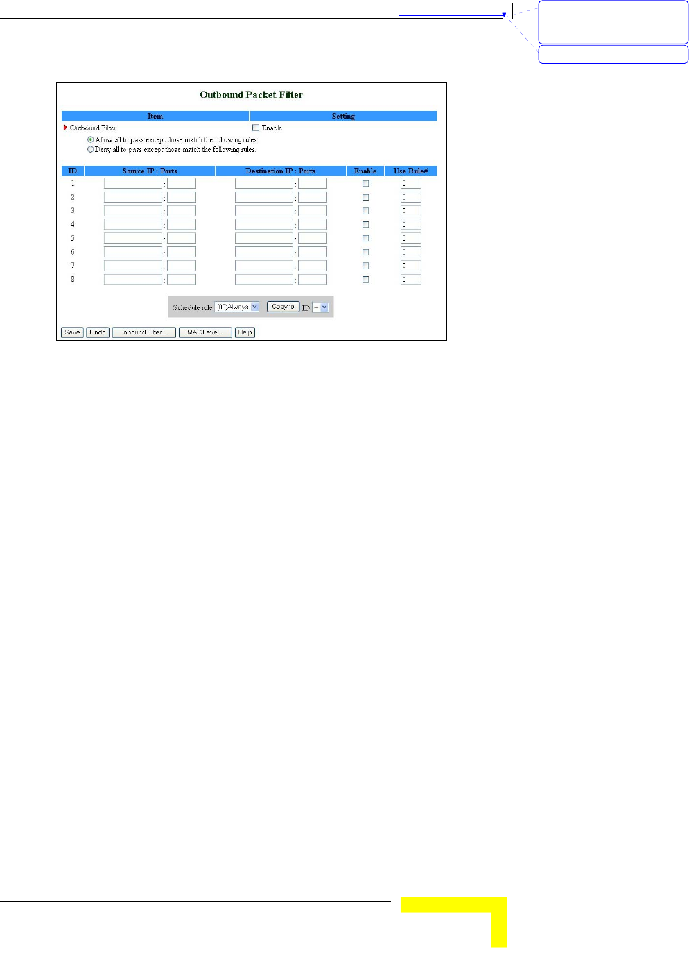
Packet Filters
Packet Filter enables you to control which packets are allowed to pass
through the networking gateway. When selecting the Packet Filters
submenu on the menu list, the Outbound Packet Filter window opens.
NOTE
The Inbound Filter… button at the bottom of the window toggles between the
Outbound and Inbound Packet Filter windows. The button's text will change from
Inbound Filter… to Outbound Filter… accordingly.
刪除: 3
刪除: 3
刪除: Operation and
Administration
刪除: MAC Address Control
allows you to assign
different access rights for
different users and to assign
a fixed IP address to a
specific MAC address.
刪除: Operation and
Administration
錯誤! 尚未定義樣式。
Wireless Networking Gateway System Manual
3-31
Figure 26: Packet Filter Initial Window
The Outbound filter applies on all outbound packets. The Inbound filter
applies only on packets that are destined to Virtual Servers or DMZ host.
You can select one of the following filtering policies:
Allow all to pass except those match the specified rules
Deny all to pass except those match the specified rules
You can specify up to 8 rules for each direction, inbound and outbound.
For each rule, you can define the following:
Source IP address – You can define a single IP address (4.3.2.1) or a
range of IP addresses (4.3.2.1-4.3.2.254). An empty field denotes all
IP addresses.
Source port address - You can define a single port (80) or a range of
ports (1000-1999). Add prefix "T" or "U" to specify a TCP or UDP
protocol. For example, T80, U53, U2000-2999. No prefix indicates
both TCP and UDP protocols. An empty field denotes all port
addresses.
Destination IP address - You can define a single IP address (4.3.2.1)
or a range of IP addresses (4.3.2.1-4.3.2.254). An empty field
denotes all IP addresses.
Destination port address - You can define a single port (80) or a
range of ports (1000-1999). Add prefix "T" or "U" to specify a TCP or
UDP protocol. For example, T80, U53, U2000-2999. No prefix
indicates both TCP and UDP protocols. An empty field denotes all
port addresses.
刪除: Set TCP/IP Protocol
for Working with NAT
Router
刪除: Wizard
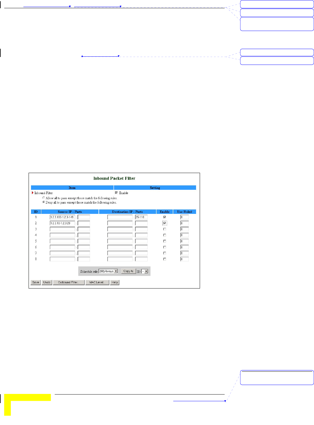
Chapter 錯誤! 尚未定義樣式。 - 錯誤! 尚未定義樣式。
錯誤! 尚未定義樣式。
3-32
Enable – Check to enable the rule. Each rule can be enabled or
disabled individually.
Use Rule# - Packet Filter can work with Scheduling Rules. For details,
please refer to Schedule Rule on page 3-52.
Schedule rule – Facilitates the process of selecting a scheduling rule
for each ID.
Click Save to save your Inbound/Outbound Packet Filter settings.
Inbound Filter
To enable Inbound Packet Filter click on the Inbound Filter button and
check the Enable box in the Inbound Packet Filter window.
In the following examples, the SMTP Server (25), POP Server (110), Web
Server (80), FTP Server (21), and News Server (119) are defined in the
Virtual Server or DMZ Host.
Example 1:
Figure 27: Inbound Packet Filter – Example 1
In this example, IPs (1.2.3.100-1.2.3.149) are allowed to send mail (port
25), receive mail (port 110), and browse the Internet (port 80).
IPs (1.2.3.10-1.2.3.20) are allowed to perform all operations.
All other IPs are all blocked from performing any operation.
刪除: 3
刪除: 3
刪除: Operation and
Administration
格式化: 字型: 斜體
刪除: Schedule Rule
刪除: Operation and
Administration
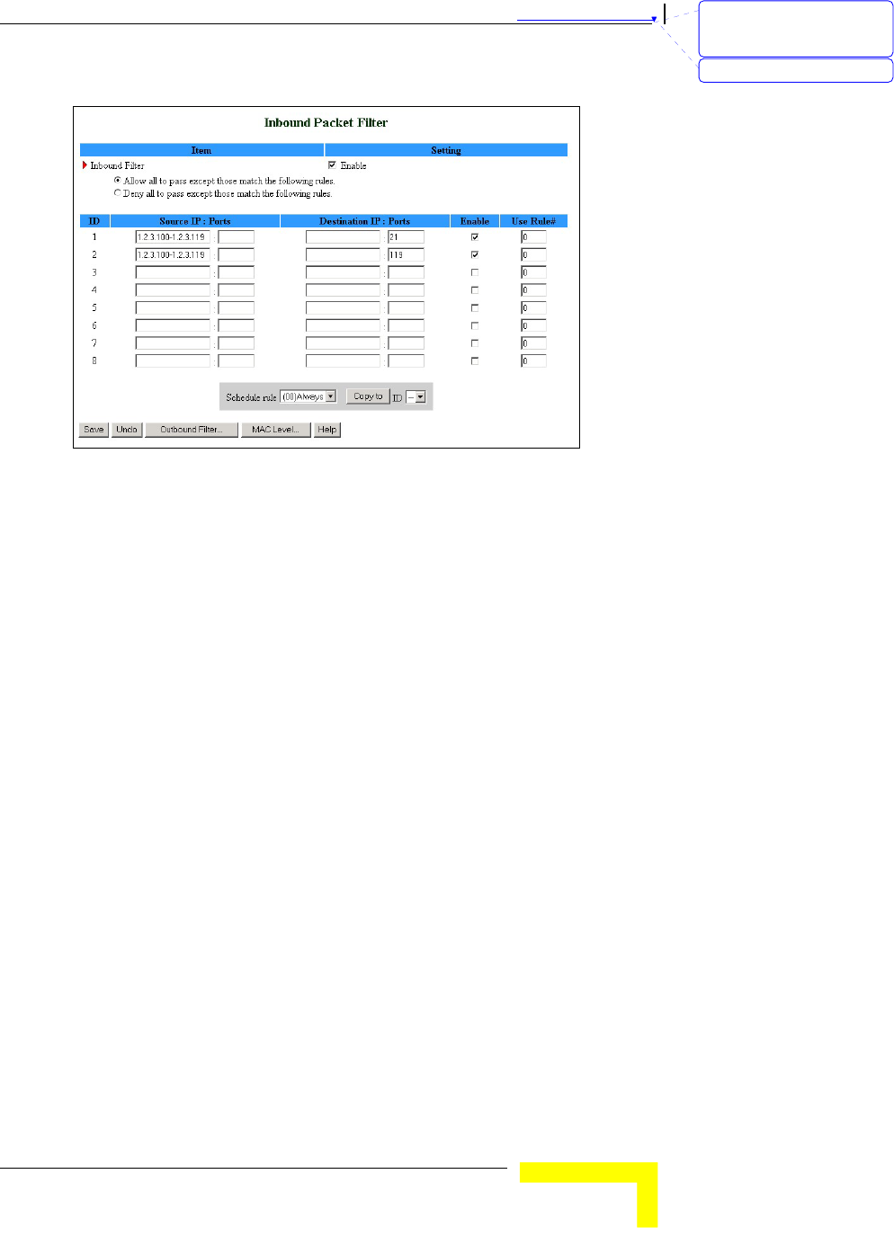
錯誤! 尚未定義樣式。
Wireless Networking Gateway System Manual
3-33
Example 2:
Figure 28: Inbound Packet Filter - Example 2
In this example, IPs (1.2.3.100-1.2.3.119) are allowed to do everything
except read net news (port 119) and transfer files via FTP (port 21).
All other IPs are all allowed to perform all operations.
Outbound Filter
To enable Outbound Packet Filter, click on the Outbound Filter button
and check the Enable box in the Outbound Packet Filter window.
刪除: Set TCP/IP Protocol
for Working with NAT
Router
刪除: Wizard
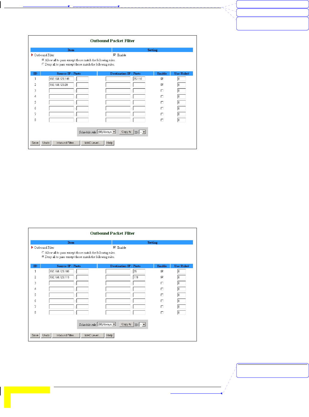
Chapter 錯誤! 尚未定義樣式。 - 錯誤! 尚未定義樣式。
錯誤! 尚未定義樣式。
3-34
Example 1:
Figure 29: Outbound Packet Filter - Example 1
In this example, IP (192.168.123.149) is restricted from sending mail
(port 25), receiving mail (port 110), and browsing the Internet (port 80).
It is allowed to perform all other operations.
IP (192.168.123.20) is blocked from performing any operation.
All other IPs are allowed to perform all operations.
Example 2:
Figure 30: Outbound Packet Filter - Example 2
刪除: 3
刪除: 3
刪除: Operation and
Administration
刪除: Operation and
Administration
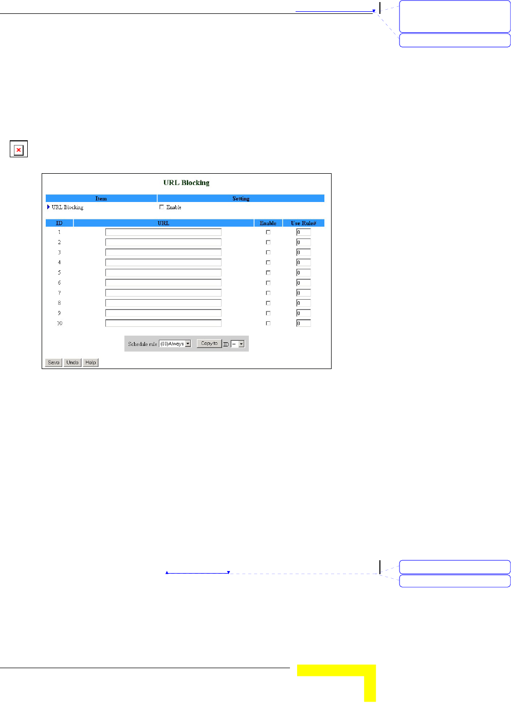
錯誤! 尚未定義樣式。
Wireless Networking Gateway System Manual
3-35
In this example, IPs (192.168.123.100) and (192.168.123.119) can only
read net news (port 119) and send mail (port 25). They are blocked from
performing any other operation.
All other IPs are blocked from performing any operation.
URL Blocking
When enabled, this feature blocks LAN computers from connecting to
pre-defined Web sites.
Figure 31: URL Blocking
Enter the following parameters:
URL Blocking – Enable/Disable - Check to enable the URL Blocking
feature.
URL - If any part of the Web site's URL matches the pre-defined
word specified in this field, the connection will be blocked.
For example, you can use a pre-defined word "sex" to block all Web
sites whose URLs contain the word "sex".
Enable - Checked to enable the rule. Each rule can be enabled or
disabled individually.
Use Rule# - URL Blocking can work with Scheduling Rules. For
details, please refer to Schedule Rule on page 3-52.
Schedule rule – Facilitates the process of selecting a scheduling rule
for each ID.
Click Save to save your settings.
刪除: Set TCP/IP Protocol
for Working with NAT
Router
刪除: Wizard
格式化: 字型: 斜體
刪除: Schedule Rule
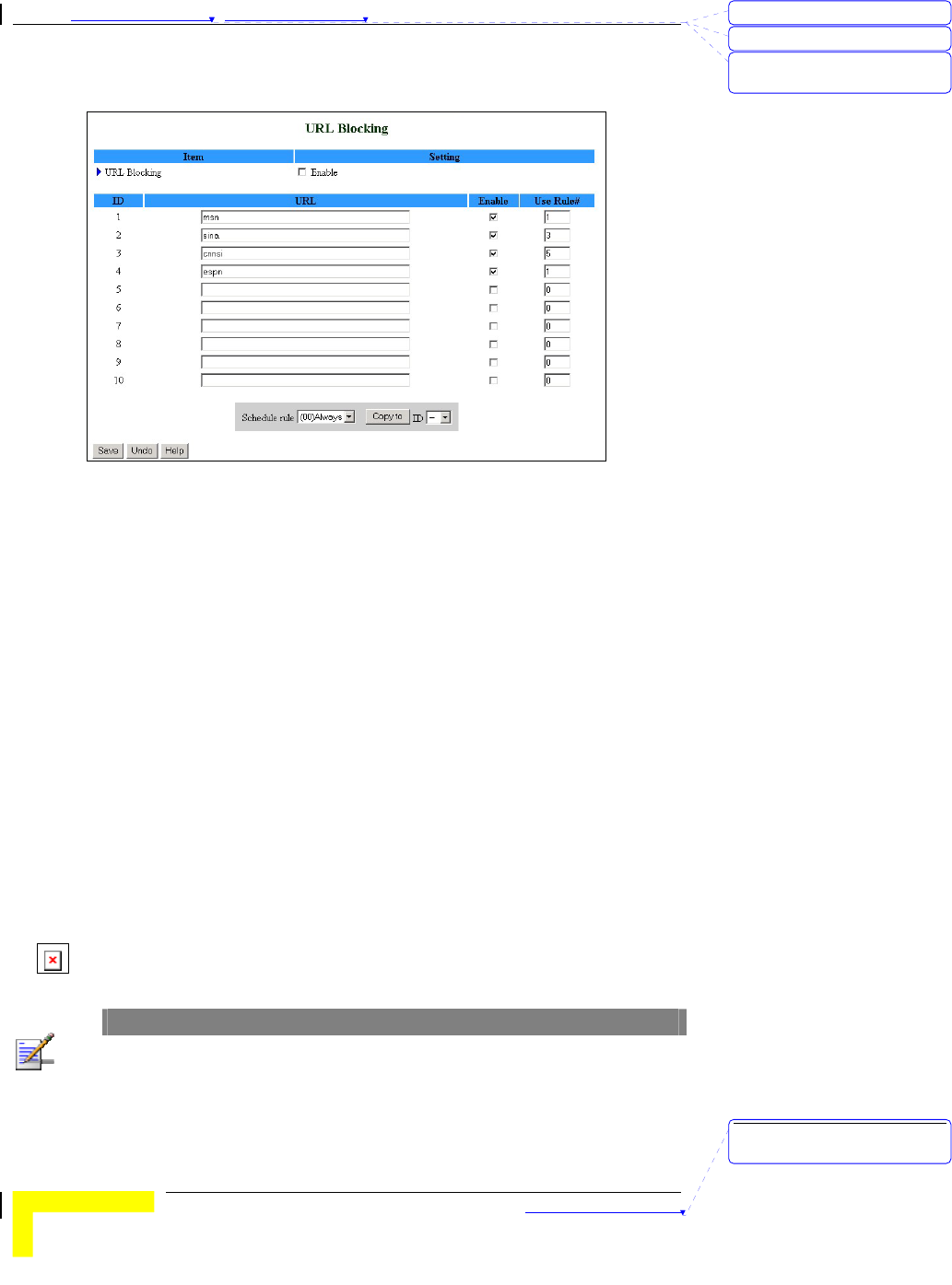
Chapter 錯誤! 尚未定義樣式。 - 錯誤! 尚未定義樣式。
錯誤! 尚未定義樣式。
3-36
URL Blocking - Example
Figure 32: URL Blocking Example
In this example:
1. All URLs which include the string "msn" will be blocked, and the
action will be recorded in the log file.
2. All URLs which include the string "sina" will be blocked, and the
action will be recorded in the log file.
3. All URLs which include the string "cnnsi" will be blocked, and the
action will be recorded in the log file.
4. All URLs which include the string "espn" will be blocked, and the
action will be recorded in the log file.
If the Enable box is not checked for a specific rule, the rule will not be
applied and the matching URLs will not be blocked.
Domain Filter
When enabled, the Domain Filter feature blocks LAN computers from
connecting to pre-defined Web sites.
NOTE
While URL Blocking uses keywords to block all Web sites whose URL includes the pre-
specified keyword, Domain Filter blocks a single pre-defined Web site by specifying the
suffix (such as .com, .org, etc.).
刪除: 3
刪除: 3
刪除: Operation and
Administration
刪除: Operation and
Administration
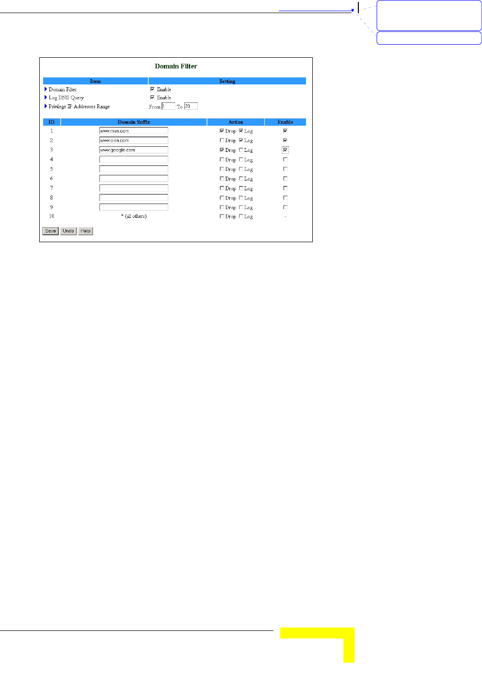
錯誤! 尚未定義樣式。
Wireless Networking Gateway System Manual
3-37
Figure 33: Domain Filter
Up to 9 Domain Suffixes can be defined, and for each rule you can
specify the desired action to be taken when a user attempts to access
that domain. For each rule you can define the following:
Domain Filter – Check to enable the Domain Filter feature to
prevent users from accessing specific URLs.
Log DNS Query – Check to enable logging users' attempts to enter
the specified URLs.
Privilege IP Addresses Range – Sets a group of hosts and allows
them to access the network without restriction. (From: 1~254, To:
1~254)
Domain Suffix - A suffix of URL to be restricted. For example, ".com",
"xxx.com".
Action – You can specify the type of action you want performed
when someone attempts to access the specific URL that meets the
domain-suffix:
¾ Drop – Check to block access.
¾ Log – Check to log the access attempt.
Enable - Check to enable the rule. Each rule can be
enabled/disabled individually.
In the example above (Figure 33):
刪除: Set TCP/IP Protocol
for Working with NAT
Router
刪除: Wizard
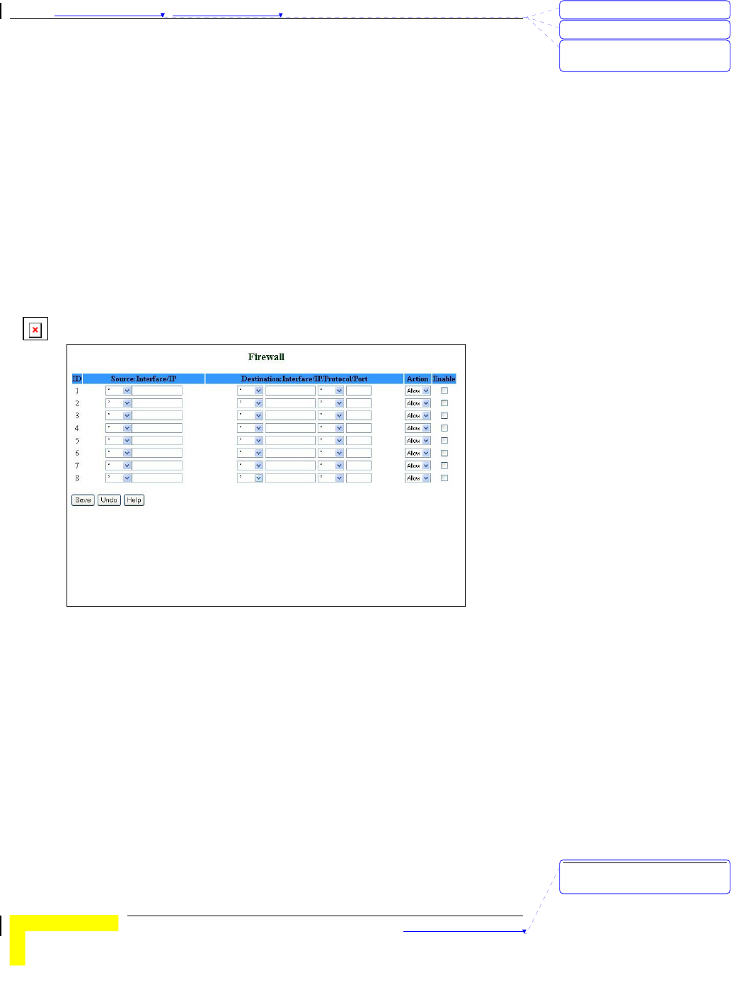
Chapter 錯誤! 尚未定義樣式。 - 錯誤! 尚未定義樣式。
錯誤! 尚未定義樣式。
3-38
1. The URL "www.msn.com" will be blocked, and the action will be
recorded in the log file.
2. The URL "www.sina.com" will not be blocked, but any attempt to
enter the Web site will be recorded in the log file.
3. The URL "www.google.com" will be blocked, but the action will
not be recorded in the log file.
4. IP address X.X.X.1~ X.X.X.20 can access network without
restriction.
Click Save to save your settings.
Firewall
Firewall rules deny/allow traffic from passing through the device.
Figure 34: Firewall
Up to 8 rules can be specified for each direction of traffic: inbound and
outbound. For each rule, you can define the following:
Source IP address, from LAN to WAN
Destination IP address, from LAN to WAN
Destination Protocol: TCP, UPD or ICMP
Destination port number
Action – Allow/Deny (default – Allow)
Enable – Check to enable the rule. Each rule can be
enabled/disabled individually.
刪除: 3
刪除: 3
刪除: Operation and
Administration
刪除: Operation and
Administration
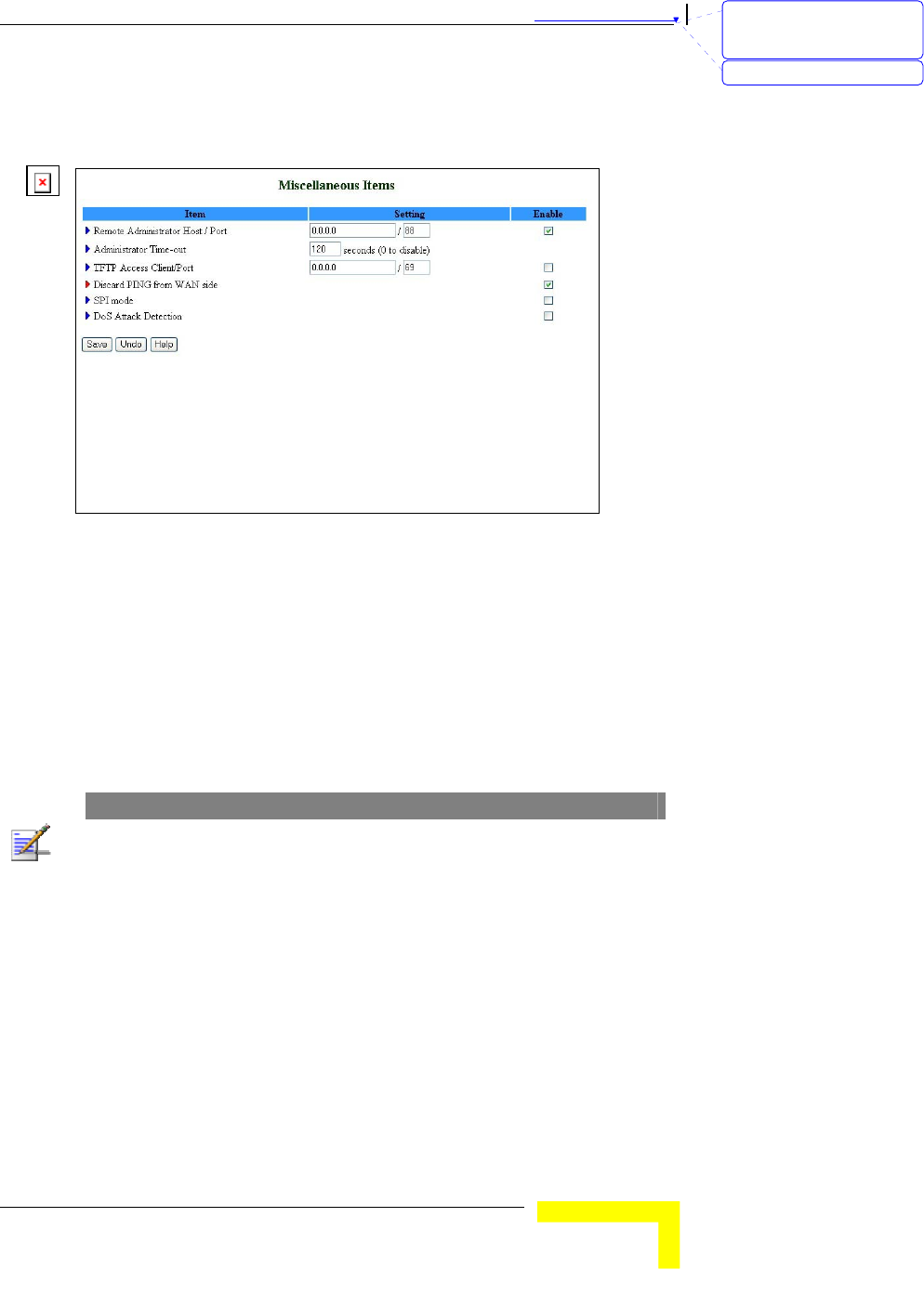
錯誤! 尚未定義樣式。
Wireless Networking Gateway System Manual
3-39
Click Save to save your settings.
Miscellaneous Items
Figure 35: Miscellaneous Items
From the Miscellaneous Items window you can set the following:
Remote Administrator Host/Port - Enables the user to perform
administration tasks from a remote host. When enabled, only the
specified IP address can perform remote administration. If the
specified IP address is 0.0.0.0, any host can connect to this device
in order to perform administration tasks. You can use subnet mask
bits "/nn" notation to specify a group of trusted IP addresses. For
example, "10.1.2.0/24".
NOTE
When Remote Administration is enabled, the web server port will automatically
change to 88. You can change the web server port to another port.
Administrator Time-out - The time of no activity to logout
automatically. Set it to zero to disable automatic time-out.
TFTP Access Client/Port – When enabled, the specified IP address
with the specified port can access the device through the TFTP client
utility.
Discard PING from WAN side - When enabled, any ping packet from
WAN will be discarded.
刪除: Set TCP/IP Protocol
for Working with NAT
Router
刪除: Wizard