Advance Multimedia Internet Technology CPE-IDUNG-4D1W Wireless 11g Networking product User Manual Part 2
Advance Multimedia Internet Technology Inc. Wireless 11g Networking product Users Manual Part 2
Contents
- 1. Users Manual Part 1
- 2. Users Manual Part 2
Users Manual Part 2

Chapter 錯誤! 尚未定義樣式。 - 錯誤! 尚未定義樣式。
錯誤! 尚未定義樣式。
3-40
SPI Mode - When enabled, the router records the information, such
as IP address, port address, ACK, SEQ number and so on, of the
packets that pass through the gateway. The Networking Gateway
checks every incoming packet to detect whether it is valid.
DoS Attack Detection - When enabled, the router detects and logs
the DoS attack that comes from the Internet. Currently, the
Networking Gateway can detect the following DoS attack: SYN
Attack, WinNuke, Port Scan, Ping of Death, and Land Attack etc.
刪除: 3
刪除: 3
刪除: Operation and
Administration
刪除: Operation and
Administration
錯誤! 尚未定義樣式。
Wireless Networking Gateway System Manual
3-41
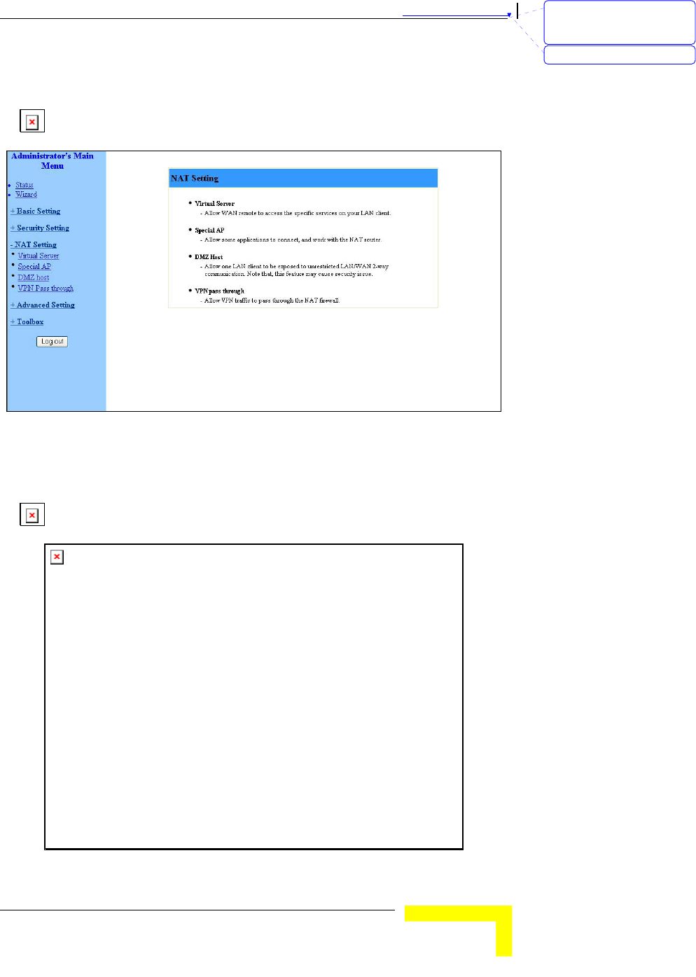
NAT Setting
The NAT Setting page provides access to configuring the virtual server,
special AP, DMZ host and VPN pass through.
Figure 36: NAT Setting
Virtual Server
Virtual Server enables WWW, FTP and other services on your LAN to be
accessible to Internet users.
Figure 37: Virtual Server
刪除: Set TCP/IP Protocol
for Working with NAT
Router
刪除: Wizard
Chapter 錯誤! 尚未定義樣式。 - 錯誤! 尚未定義樣式。
錯誤! 尚未定義樣式。
3-42
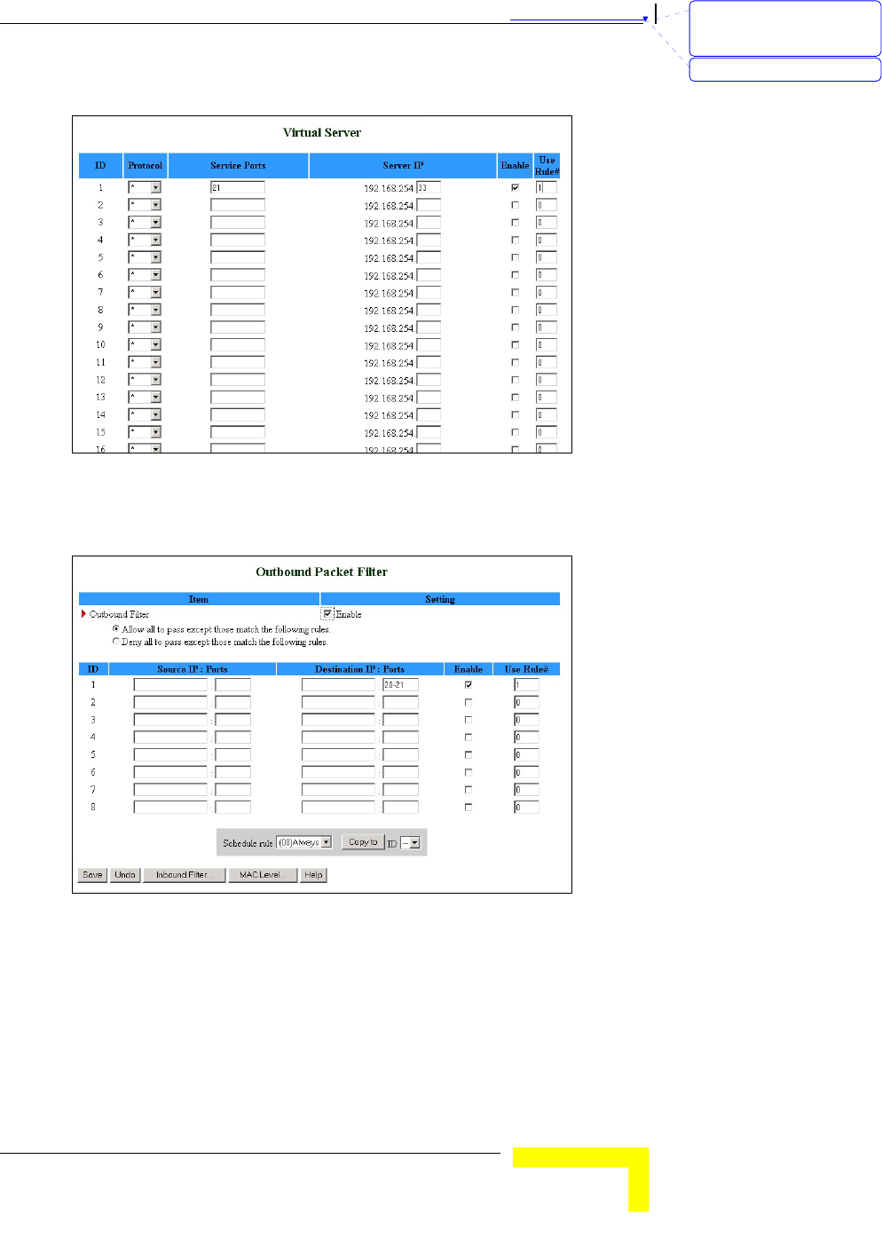
Specify the following parameters for each ID:
Protocol – Select from TCP, UDP, * (all). (the default setting is *).
Service Ports – Enter a port number, or a range of ports.
Server IP – Enter the server IP (the range is 1~254).
Enable – Check to enable the rule. Each rule can be
enabled/disabled individually.
Use Rule# - Virtual Server can work with Scheduling Rules. For
details, please refer to Schedule Rule on page 3-52.
In addition, the Virtual Server page allows to easily select services from
a pre-defined list, and to assign to them a pre-defined rule.
Well known services – Select a service from the list of pre-defined
services.
Schedule rule – Facilitates the process of selecting a scheduling rule
for each ID.
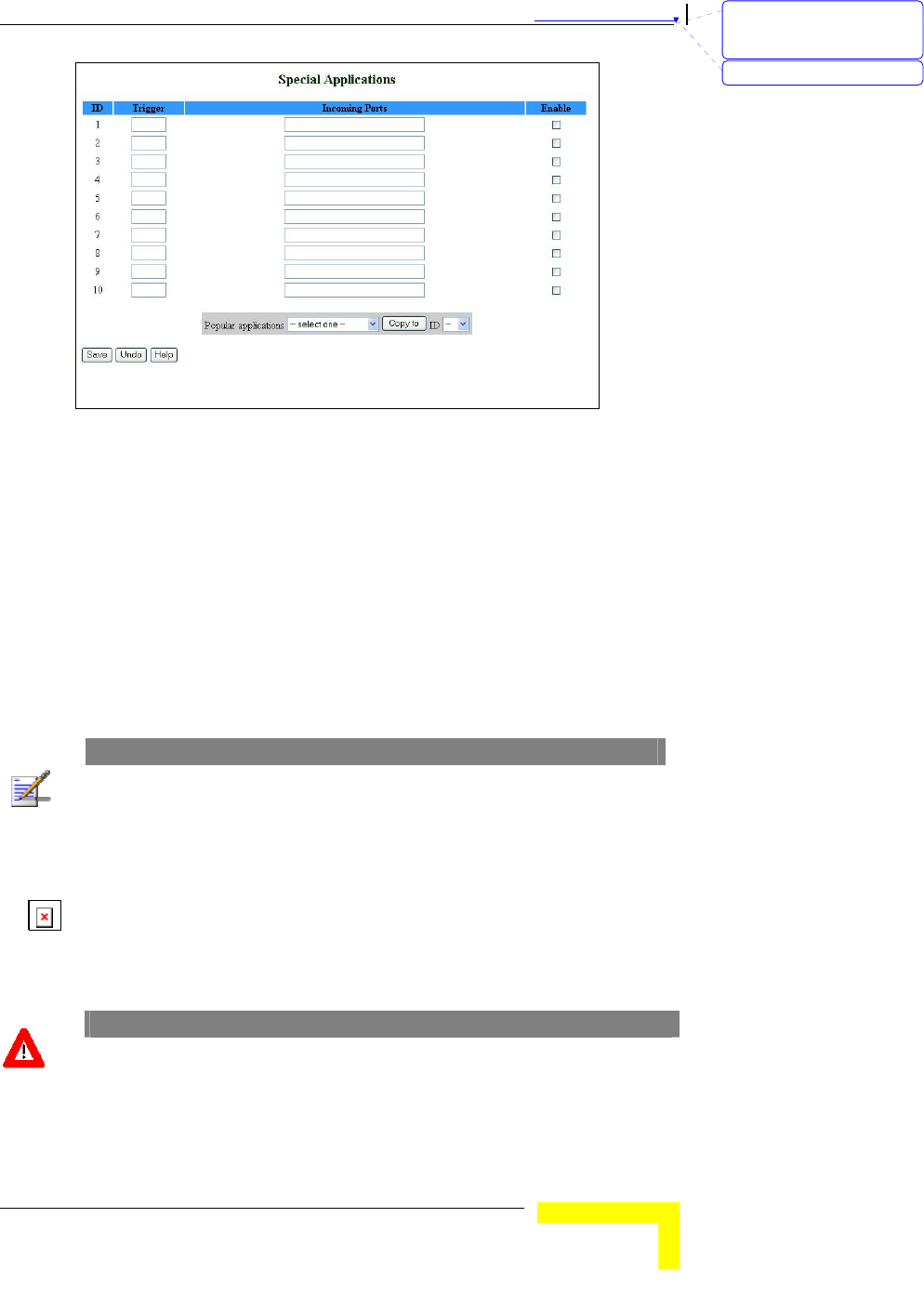
Special AP
Some applications, such as Internet games, Video conferencing, Internet
telephony etc., require multiple connections. Because of the firewall
function, these applications cannot work with a pure NAT router. The
Special Applications window makes some of these applications work
with NAT router.
NOTE
Only one PC at a time can use each Special Application.
刪除: 3
刪除: 3
刪除: Operation and
Administration
格式化: 字型: 斜體
刪除: Schedule Rule
刪除: Operation and
Administration
錯誤! 尚未定義樣式。
Wireless Networking Gateway System Manual
3-43
Figure 38: Special Applications
Trigger – The outbound port number issued by the application.
Incoming Ports – When the trigger packet is detected, the inbound
packets to the specified port numbers are allowed to pass through
the firewall.
Enable – Check to enable the rule. Each rule can be
enabled/disabled individually.
Some predefined settings are provided. Select an application from the
pre-defined list, select the ID number (1-10) and click Copy to, to add
the predefined setting to your list.
NOTE
If Special Applications fails to make an application work, try DMZ host instead.
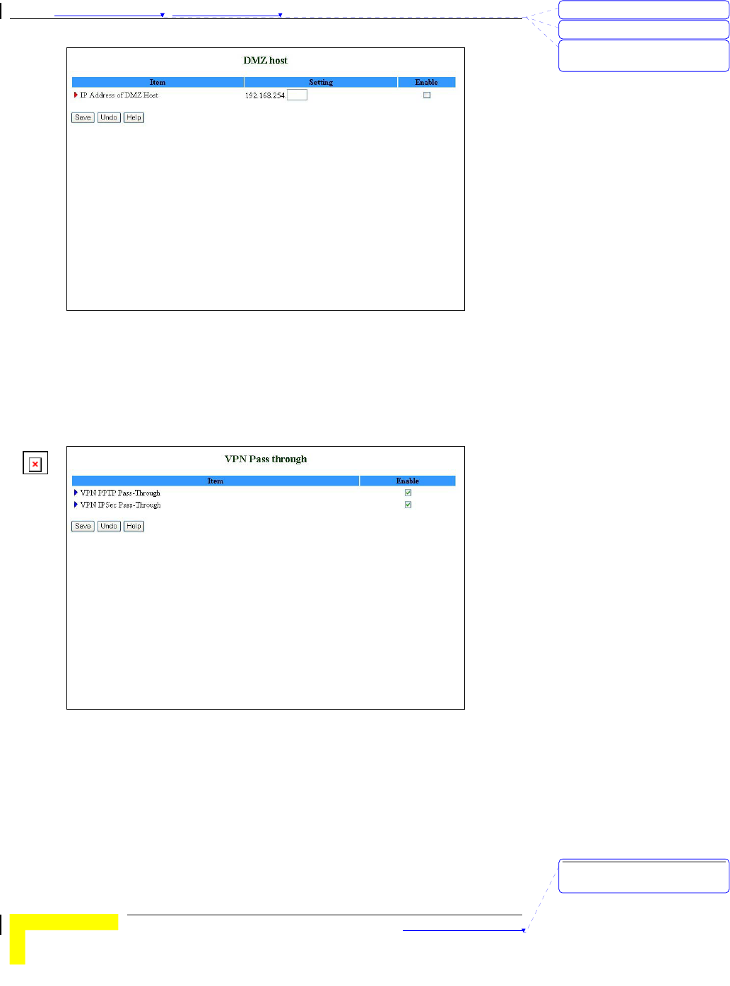
DMZ Host
Demilitarized Zone (DMZ) Host is a host without the firewall protection.
It allows a computer to be exposed to unrestricted 2-way
communication for Internet games, Video conferencing, Internet
telephony, and other special applications.
CAUTION
This feature exposes your computer and may cause security issues.
刪除: Set TCP/IP Protocol
for Working with NAT
Router
刪除: Wizard
Chapter 錯誤! 尚未定義樣式。 - 錯誤! 尚未定義樣式。
錯誤! 尚未定義樣式。
3-44
Figure 39: DMZ Host
Check the Enable box to enable this feature. One IP address should be
set on the subnet of LAN.
VPN Pass Through
Figure 40: VPN Pass Through
VPN PPTP Pass-Through – Check to enable PPTP connection to pass
through the device.
VPN IPSec Pass-Through – Check to enable IPSec connection to pass
through the device.
刪除: 3
刪除: 3
刪除: Operation and
Administration
刪除: Operation and
Administration
錯誤! 尚未定義樣式。
Wireless Networking Gateway System Manual
3-45
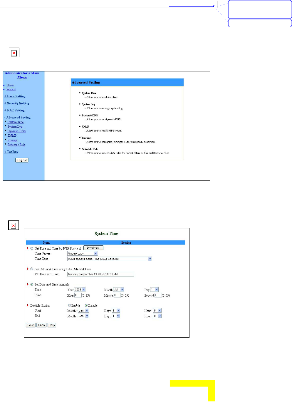
Advanced Settings
The Advanced Settings menu provides access to configuring additional
features, such as System Time, Log, Dynamic DNS, SNMP, Routing and
Scheduling Rules.
Figure 41: Advanced Setting
System Time
The System Time window enables to set the device time.
Figure 42: System Time
From the System Time window, you can select one of the following ways
to set the date and time of the device:
刪除: Set TCP/IP Protocol
for Working with NAT
Router
刪除: Wizard
Chapter 錯誤! 尚未定義樣式。 - 錯誤! 尚未定義樣式。
錯誤! 尚未定義樣式。
3-46
Get Date and Time by NTP Protocol - Select if you want to set the
device's internal clock using the Network Time Protocol (NTP).
¾ Time Server - Select an NTP time server to consult UTC time.
¾ Time Zone - Select a time zone where this device is located.
¾ Sync Now! - Synchronize system time with network time
server (alternatively, synchronization will be performed
automatically from time to time).
Set Date and Time using PC's Date and Time – Select if you want
the device's internal clock to synchronize with the PC's clock.
Set Date and Time manually - Select if you want to manually set the
device's internal clock. You need to specify:
¾ Date: Year, Month, Day
¾ Time: Hours (0-23), Minutes (0-59), Seconds (0-59).
¾ TBD – The clock is set upon clicking Save.
NOTE
The device time is displayed at the bottom of the Status window.
In addition, you can specify daylight saving time as follows:
Daylight Saving - Enable/disable Daylight Saving and set start and
end time of daylight saving time range.
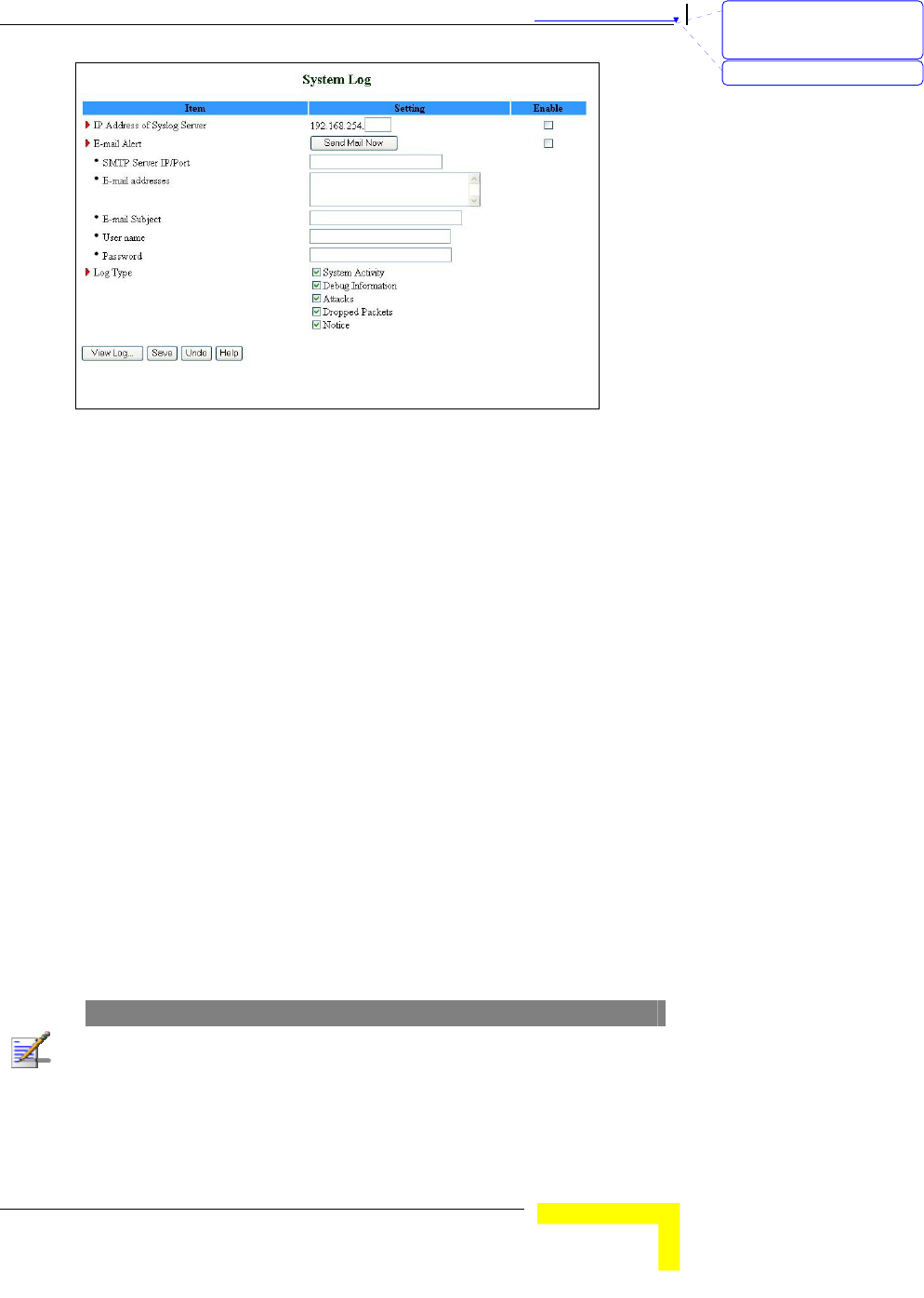
System Log
System Log enables to set parameters for exporting system logs to a
specified destination. Two exporting methods are supported: syslog
(UDP) and SMTP (TCP).
刪除: 3
刪除: 3
刪除: Operation and
Administration
刪除: Operation and
Administration
錯誤! 尚未定義樣式。
Wireless Networking Gateway System Manual
3-47
Figure 43: System Log
IP Address for Syslog Server – Enter the IP address of the syslog
server. It is valid only on your subnet LAN. Check to Enable this
function.
E-mail Alert Enable - Check if you want to enable Email alert (send
syslog via email).
¾ SMTP Server IP and Port - Enter the SMTP server IP and port,
which are concatenate with ':'.For example,
"mail.your_url.com" or "192.168.1.100:26". If you do not
specify port number, the default value is 25.
¾ E-mail addresses - The listed recipients will receive these
logs. You can assign more than 1 recipient, using a semi-
colon (;) or a comma (,) to separate the addresses.
¾ E-mail Subject - The subject of email alert. This setting is
optional.
¾ Username and Password - To fill some SMTP server's
authentication requirement, you may need to enter the
Username and Password provided by your ISP.
Log Type - Select the activities to be logged.
NOTE
The changes made in the System Log page become effective upon clicking Save.
Rebooting the system is not required.
刪除: Set TCP/IP Protocol
for Working with NAT
Router
刪除: Wizard
Chapter 錯誤! 尚未定義樣式。 - 錯誤! 尚未定義樣式。
錯誤! 尚未定義樣式。
3-48
To view the system log:
Click on the View Log… button at the bottom of the screen. The System
Log opens (see View Log on page 3-56, Figure 54)
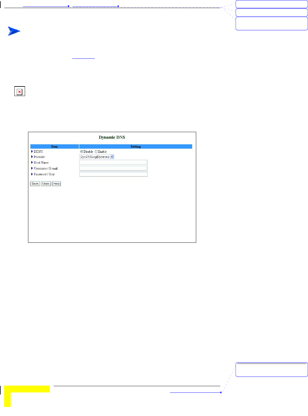
Dynamic DNS
To host your server on a changing IP address, you need to use a
Dynamic Domain Name Service (DDNS).
To reach your host, one needs to know its name. Dynamic DNS will map
the name of your host to your current IP address, which changes each
time you connect to your Internet service provider.
Figure 44: Dynamic DNS
Before enabling Dynamic DNS, you need to register an account on of
the Dynamic DNS servers listed here under Provider. Upon registration,
you will receive your account details.
DDNS - Click Enable or Disable to enable/disable Dynamic DNS,
Provider – Select from the list of Dynamic DNS servers on which you
have an account.
Host Name – Enter to register a domain name to the DDNS provider.
The full domain name is concatenated with the specified Host Name
and a suffix, specified by the DDNS provider.
Username/E-mail – Enter your Username or E-mail address
according to the DDNS provider you selected.
刪除: 3
刪除: 3
刪除: Operation and
Administration
刪除: Operation and
Administration
錯誤! 尚未定義樣式。
Wireless Networking Gateway System Manual
3-49
Password/Key – Enter your password or key according to the DDNS
provider you selected.
After Dynamic DNS setting is configured, click Save.
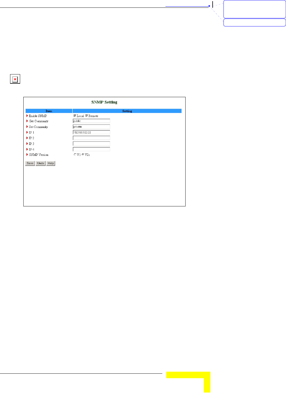
SNMP Setting
The Simple Network Management Protocol (SNMP) provides the user
with the capability to remotely manage a computer network by polling
and setting terminal values and monitoring network events.
Figure 45: SNMP Setting
Enable SNMP - You must check either Local or Remote or both to
enable SNMP function.
¾ Local - The device will respond to requests from LAN.
¾ Remote – The device will respond to requests from WAN.
Get Community – Set the password for GetRequest access rights to
your device.
Set Community - Setting the password for SetRequest access rights
to your device.
IP 1,IP 2,IP 3,IP 4 - Enter your SNMP addresses for allowed
managers. The user has to configure to where this device should
send SNMP Trap messages.
SNMP Version - Select the proper SNMP Version supported by your
SNMP Management software.
In the above figure:
刪除: Set TCP/IP Protocol
for Working with NAT
Router
刪除: Wizard
Chapter 錯誤! 尚未定義樣式。 - 錯誤! 尚未定義樣式。
錯誤! 尚未定義樣式。
3-50
The device will respond to requests from both LAN and WAN.
The device will respond to SNMP clients whose get community is
set as "public".
The device will respond to SNMP clients whose set community is
set as "private".
This device will send SNMP Trap messages to 192.168.123.33
(Using SNMP Version V2c).
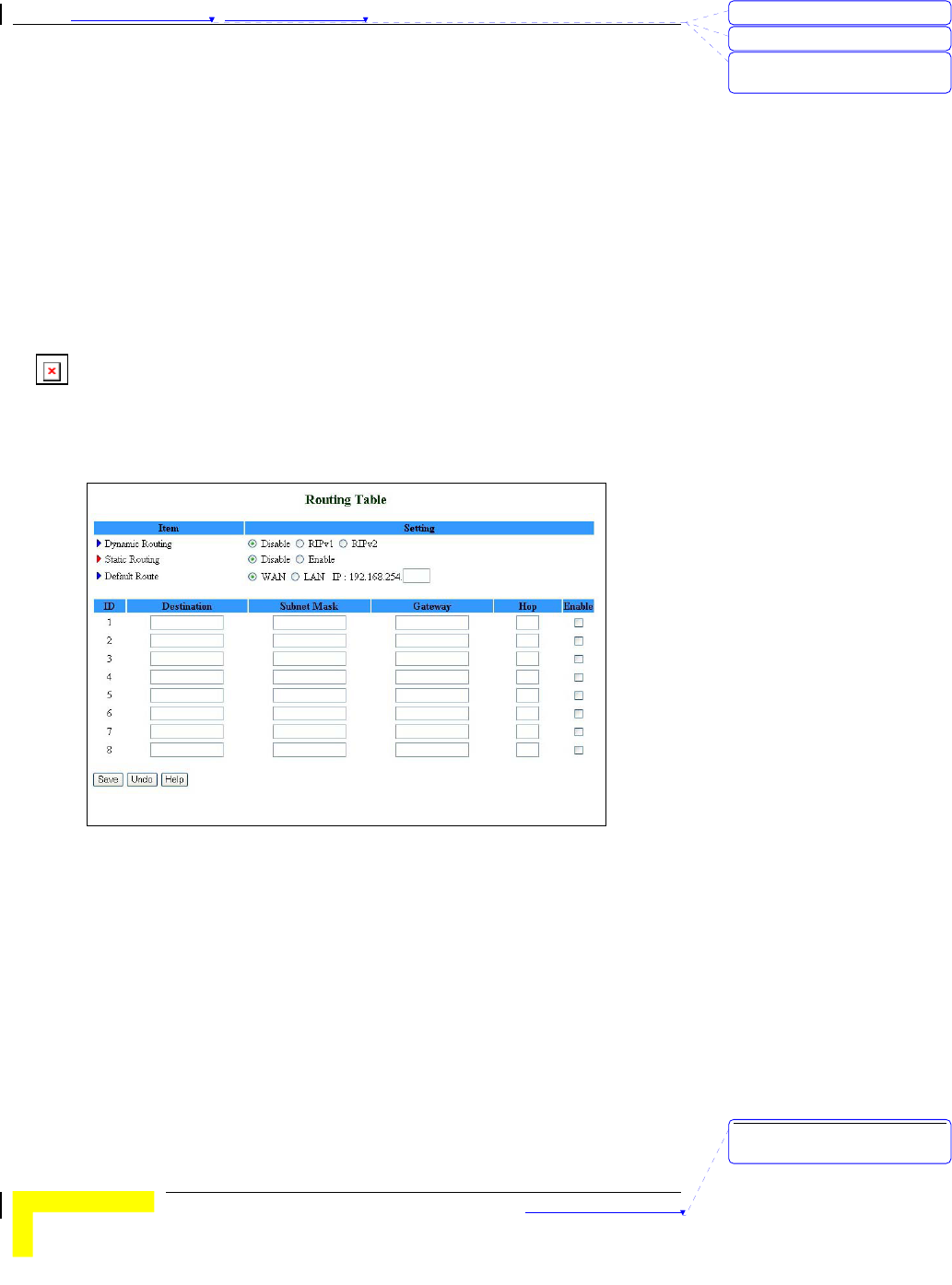
Routing Table
Routing allows you to determine which physical interface address to use
for outgoing IP data grams. If you have more than one gateway and
subnet, you will need to enable Routing Table to allow packets to find
the proper routing path and allow different subnets to communicate
with each other.
Figure 46: Routing Table
Routing Table settings are settings used to setup the functions of static
and dynamic routing.
Dynamic Routing - Routing Information Protocol (RIP) will exchange
information on destinations for computing routes throughout the
network. Select RIPv2 only if you have a different subnet on your
network. Otherwise, select RIPv1 if you need this protocol.
刪除: 3
刪除: 3
刪除: Operation and
Administration
刪除: Operation and
Administration

錯誤! 尚未定義樣式。
Wireless Networking Gateway System Manual
3-51
Static Routing: For static routing, you can specify up to 8 routing
rules. You can enter the destination IP address, subnet mask, and
gateway, hop for each routing rule, and enable/disable the
individual rule.
Default Route: Sets the default route interface as WAN or LAN. For
LAN, one IP for routing must be set.
刪除: Set TCP/IP Protocol
for Working with NAT
Router
刪除: Wizard
Chapter 錯誤! 尚未定義樣式。 - 錯誤! 尚未定義樣式。
錯誤! 尚未定義樣式。
3-52
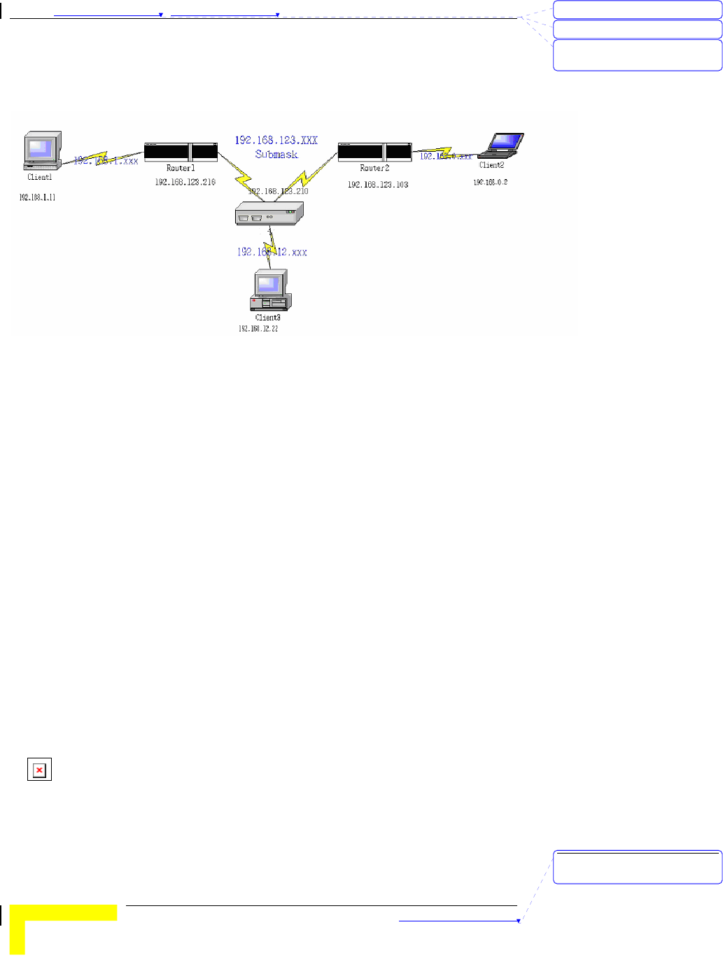
Example:
Configuration on NAT Router
Destination Subnet Mask Gateway Hop Enabled
192.168.1.0 255.255.255.0 192.168.123.216 1 ˇ
192.168.0.0 255.255.255.0 192.168.123.103 1 ˇ
If, for example, Client3 wanted to send an IP data gram to 192.168.0.2
(Client2), he would use the above table to determine that he had to go
via 192.168.123.103 (Gateway2).
And if he sends Packets to 192.168.1.11 he will go via 192.168.123.216
(Gateway1).
Each rule can be enabled or disabled individually.
After the Routing Table setting is configured, click Save.
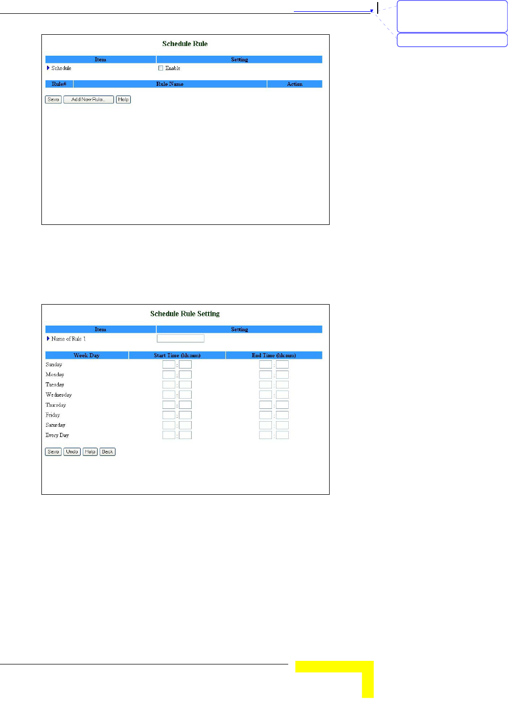
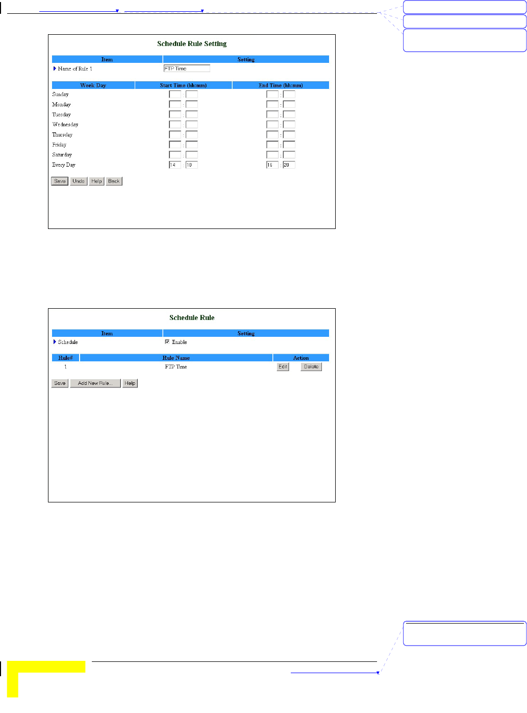
Schedule Rule
Schedule Rule allows you to set the schedule time for which a service
will be turned on or off.
刪除: 3
刪除: 3
刪除: Operation and
Administration
刪除: Operation and
Administration
錯誤! 尚未定義樣式。
Wireless Networking Gateway System Manual
3-53
Figure 47: Schedule Rule
Schedule Enable - Selected if you want to Enable the Scheduler.
Click Add New Rule to add a rule to the list. The Schedule Rule
Setting window opens.
Figure 48: Schedule rule Setting
You can enter a rule name and set which day and what time to
schedule from “Start Time” to “End Time”. In the following example, a
rule named "FTP Time" is scheduled to operate every day between 14:10
and 16:20.
刪除: Set TCP/IP Protocol
for Working with NAT
Router
刪除: Wizard
Chapter 錯誤! 尚未定義樣式。 - 錯誤! 尚未定義樣式。
錯誤! 尚未定義樣式。
3-54
Figure 49: Schedule Rule Setting – Example Step 1
After configuring Rule 1, click on Save to save the rule and return to
the Schedule Rule window. The new rule is now displayed on the list.
Figure 50: Schedule Rule Setting – Example Step 2
Once rules are set, you can:
Edit – Click to edit the specific rule.
Delete – Click to delete the specific rule. When the rule is deleted, all
subsequent rules are automatically renumbered.
Schedule Rule can be applied to Virtual server and Packet Filter, for
example:
刪除: 3
刪除: 3
刪除: Operation and
Administration
刪除: Operation and
Administration
錯誤! 尚未定義樣式。
Wireless Networking Gateway System Manual
3-55
Example1: Virtual Server – Apply Rule#1 (ftp time: every day 14:10 to
16:20).
Figure 51: Virtual Server - Schedule Rule#1
Example2: Packet Filter – Apply Rule#1 (ftp time: every day 14:10 to
16:20).
Figure 52: Packet Filter - Schedule Rule#1
刪除: Set TCP/IP Protocol
for Working with NAT
Router
刪除: Wizard
Chapter 錯誤! 尚未定義樣式。 - 錯誤! 尚未定義樣式。
錯誤! 尚未定義樣式。
3-56
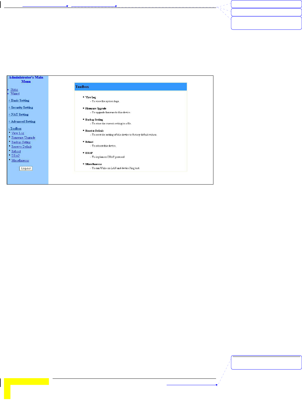
Toolbox
The Toolbox menu provides access to viewing the system log, to
firmware upgrade, backup setting, resetting the system to the factory
default values, to rebooting the system, implementing DRAP protocol,
running Wake-on-LAN and performing Ping tests.
Figure 53: Toolbox
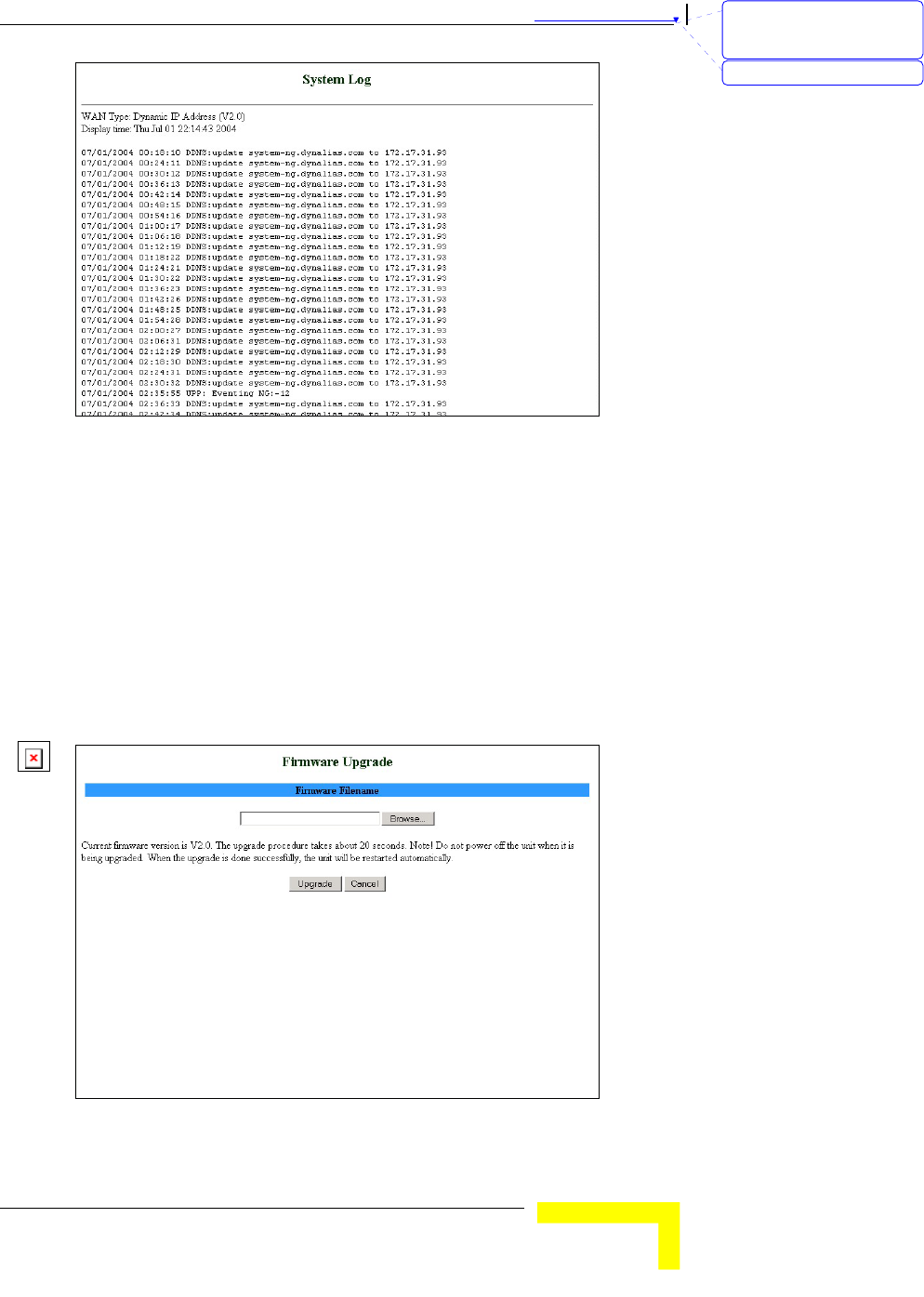
View Log
Clicking on View Log opens the System Log file. The System Log file can
also be accessed from the System Log window in the Advanced Setting
menu.
刪除: 3
刪除: 3
刪除: Operation and
Administration
刪除: Operation and
Administration
錯誤! 尚未定義樣式。
Wireless Networking Gateway System Manual
3-57
Figure 54: View System Log
While in Log View, you can:
Click Back to return to the System Log window.
Click Refresh to manually update the Log.
Click Download to download the Log file (system.log) and save it
locally.
Click Clear to clear the log file of its content.
Firmware Upgrade
Figure 55: Firmware Upgrade
刪除: Set TCP/IP Protocol
for Working with NAT
Router
刪除: Wizard
Chapter 錯誤! 尚未定義樣式。 - 錯誤! 尚未定義樣式。
錯誤! 尚未定義樣式。
3-58
To upgrade the firmware, click on Browse to browse to the file's location
and click Upgrade to begin the upgrading process, or Cancel to
terminating it.
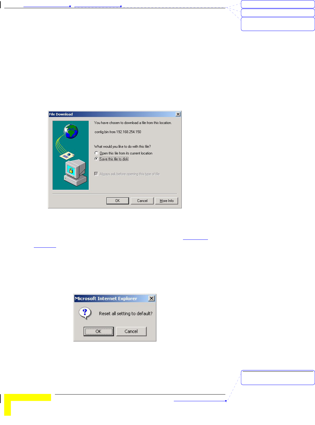
Backup Setting
Backup your settings by clicking Backup Setting in the menu list. This
automatically opens the File Download window.
Select the Save this file to disk option and click OK. Follow the
instructions on screen to save the file. The file is saved as a .bin file.
Figure 56: Backup
To restore these settings, select Firmware Upgrade from the Menu list,
browse to the .bin file you saved, and click Upgrade (see Firmware
Upgrade on page 3-57).
Reset to Default
To reset this product to factory defaults, click Reset to default in the
menu list. The following message appears.
Figure 57: Reset to Default
Click OK to reset the settings to default, or Cancel to keep the current
settings.
刪除: 3
刪除: 3
刪除: Operation and
Administration
刪除: Operation and
Administration
錯誤! 尚未定義樣式。
Wireless Networking Gateway System Manual
3-59
Reboot
To reboot the system, click Reboot in the menu list. The following
message appears.
Figure 58: Reboot
Click OK to reboot, or Cancel to continue working.
NOTE
Most of the configurations performed, require to reboot the system for them to take
effect.
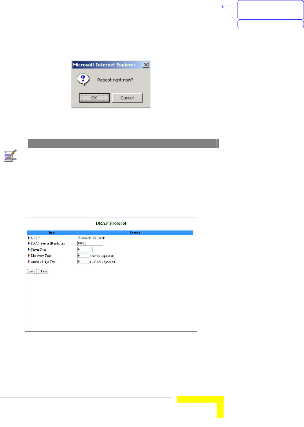
DRAP
Used for registration to the Base Station to which the SU is connected
(by performing "Discovery"). The Network Gateway's WAN IP must be in
the same subnet as the Base Station.
Figure 59: DRAP Protocol
Set the following parameters:
DRAP – Select Enable/Disable to enable/disable this feature.
DRAP Server IP Address
刪除: Set TCP/IP Protocol
for Working with NAT
Router
刪除: Wizard
Chapter 錯誤! 尚未定義樣式。 - 錯誤! 尚未定義樣式。
錯誤! 尚未定義樣式。
3-60
Server Port
Discovery Time
Acknowledge Time
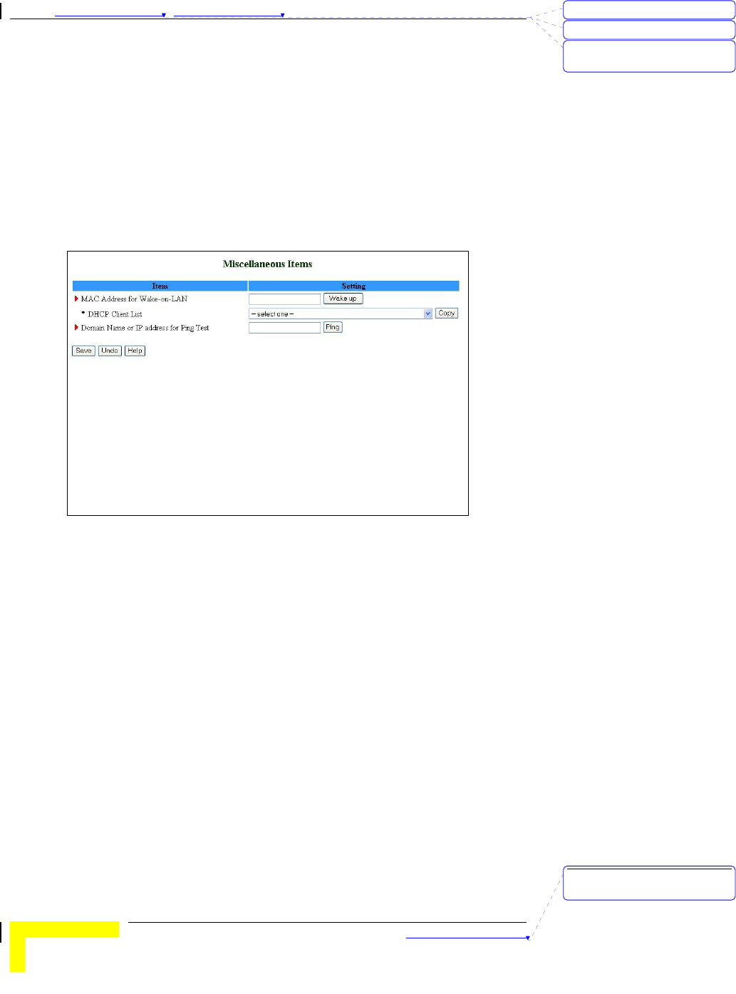
Miscellaneous Items
From the Miscellaneous Items page, you can set the MAC Address for
Wake-on-LAN, and the Domain name or IP address for performing ping
tests to the device.
Figure 60: Toolbox - Miscellaneous Items
MAC Address for Wake-on-LAN - Wake-on-LAN enables to remotely
power up a networked device. To use this feature, the target device
must be Wake-on-LAN enabled and you need to know the device's
MAC address, e.g., 00-11-22-33-44-55. Click on Wake up to have
the gateway immediately send the wake-up frame to the target
device.
¾ DHCP Client List – Select a client from the dropdown list for
which you want to perform Wake-on-LAN.
¾ Copy – Click to copy the DHCP client's MAC Address to the
Wake-on-LAN.
Domain Name or IP address for Ping Test - Allows you to configure
an IP, and ping the device. You can ping a specific IP to test that it
is up and running.
Click on Save to save your settings.
刪除: 3
刪除: 3
刪除: Operation and
Administration
刪除: Operation and
Administration
錯誤! 尚未定義樣式。
Wireless Networking Gateway System Manual
3-61
Web Configuration Server’s
Parameters Summary
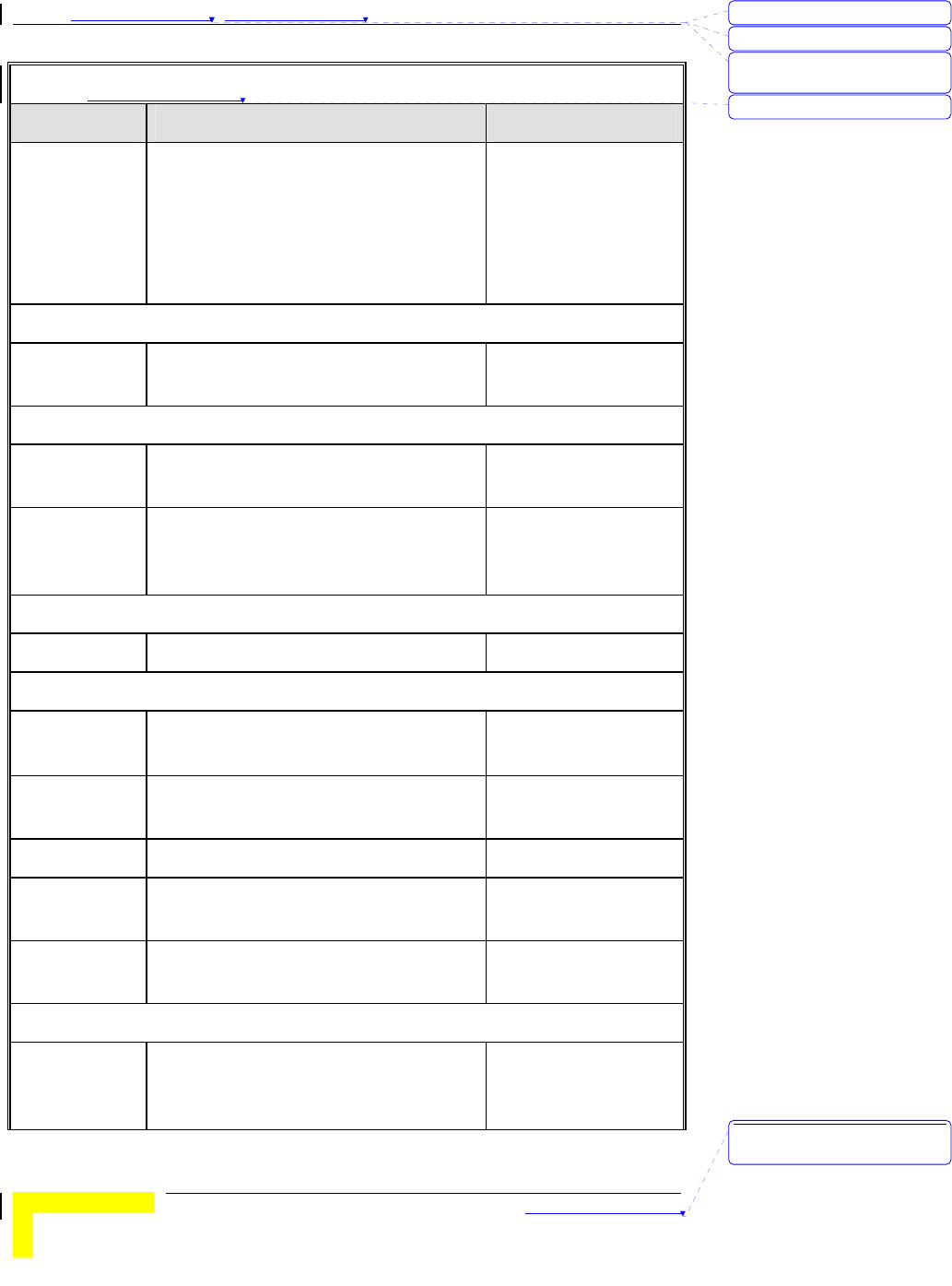
Table 錯誤! 尚未定義樣式。-3: Web Configuration Server’s Parameters Summary
Parameter Range/Options Default
Status
Printer (USB0)
Status
Not Ready
Off-line or no paper
Printing
Ready
Device error
Primary Setup
WAN Type Static IP Address
Dynamic IP Address
Dynamic IP Address with RRSM
PPP over Ethernet
PPTP
Dynamic IP Address
with RRSM
Primary Setup - Static IP Address
WAN IP
Address
x.x.x.x 0.0.0.0
WAN Subnet
Mask
x.x.x.x 255.255.255.0
WAN Gateway x.x.x.x 0.0.0.0
Primary DNS x.x.x.x 0.0.0.0
Secondary
DNS
x.x.x.x 0.0.0.0
NAT Disable Check/Uncheck Uncheck
Primary Setup - Dynamic IP Address
Host Name A string of maximum 39 characters
WAN's MAC
Address
刪除: Set TCP/IP Protocol
for Working with NAT
Router
刪除: Wizard
刪除: 3
Chapter 錯誤! 尚未定義樣式。 - 錯誤! 尚未定義樣式。
錯誤! 尚未定義樣式。
3-62
Table 錯誤! 尚未定義樣式。-3: Web Configuration Server’s Parameters Summary
Parameter Range/Options Default
Renew IP
Forever Enable
Check/Uncheck Check
NAT Disable Check/Uncheck Uncheck
Primary Setup - Dynamic IP Address with Road Runner Session Management
Account A string of maximum 53 characters
Password A string of maximum 53 characters
Login Server A string of maximum 31 characters
Renew IP
Forever
Enable Check/Uncheck Check
NAT Disable Check/Uncheck Uncheck
Primary Setup – PPP over Ethernet
PPPoE
Account
A string of maximum 53 characters
PPPoE
Password
A string of maximum 53 characters
Primary DNS x.x.x.x 0.0.0.0
Secondary
DNS
x.x.x.x 0.0.0.0
Maximum Idle
Time
0~65535 300 seconds
Connection
Control
Connect-on-demand
Auto Reconnect(always on)
Manually
Auto
Reconnect(always on)
MTU 0~9999 1492
Primary Setup - PPTP
IP Mode Dynamic IP Address
Static IP Address
Dynamic IP Address
My IP Address x.x.x.x 0.0.0.0
刪除: 3
刪除: 3
刪除: Operation and
Administration
刪除: 3
刪除: Operation and
Administration

錯誤! 尚未定義樣式。
Wireless Networking Gateway System Manual
3-63
Table 錯誤! 尚未定義樣式。-3: Web Configuration Server’s Parameters Summary
Parameter Range/Options Default
My Subnet
Mask
x.x.x.x 0.0.0.0
WAN Gateway
IP
x.x.x.x 0.0.0.0
Server IP
Address/Name
PPTP Account A string of maximum 53 characters
PPTP
Password
A string of maximum 53 characters
Connection ID (Optional)
Maximum Idle
Time
0~65535 300 seconds
Connection
Control
Connect-on-demand
Auto Reconnect(always on)
Manually
Auto
Reconnect(always on)
LAN Setup
LAN IP
Address
x.x.x.x 192.168.254.253
LAN Subnet
Mask
x.x.x.x 255.255.255.0
DHCP Server Disable
Enable
Enable
DHCP Proxy Disable
Enable
Proxy IP x.x.x.x
Disable
0.0.0.0
LAN Setup – DHCP Enabled
Range of IP
addresses Pool
Start: 1~254
End: 1~254
192.168.254.100
192.168.254.199
Domain suffix A string of maximum 31 characters
Primary DNS x.x.x.x 0.0.0.0
刪除: Set TCP/IP Protocol
for Working with NAT
Router
刪除: Wizard
刪除: 3
Chapter 錯誤! 尚未定義樣式。 - 錯誤! 尚未定義樣式。
錯誤! 尚未定義樣式。
3-64
Table 錯誤! 尚未定義樣式。-3: Web Configuration Server’s Parameters Summary
Parameter Range/Options Default
Secondary
DNS
x.x.x.x 0.0.0.0
Primary WINS x.x.x.x 0.0.0.0
Secondary
WINS
x.x.x.x 0.0.0.0
Lease Time 0~99999 0
MAC Address Control/Fixed Mapping
MAC Address
Control Enable
Check/Uncheck Uncheck
Connection
Control
Check/Uncheck
Allow/Deny
Uncheck
Deny
Connection
Control
Check/Uncheck
Allow/Deny
Uncheck
Deny
MAC Address
Rules 1-4
MAC Address A string of
maximum 32
characters
IP Address 1~254
C Check/Uncheck Uncheck
A Check/Uncheck Uncheck
Wireless Setting
Wireless
Enable
Check/Uncheck Check
Network
ID(SSID)
A string of maximum 32 characters default
Channel 1~13 1
Security None
WEP
802.1X
WPA-PSK
WPA
None
刪除: 3
刪除: 3
刪除: Operation and
Administration
刪除: 3
刪除: Operation and
Administration
錯誤! 尚未定義樣式。
Wireless Networking Gateway System Manual
3-65
Table 錯誤! 尚未定義樣式。-3: Web Configuration Server’s Parameters Summary
Parameter Range/Options Default
Advanced Wireless Setting
Beacon
Interval
1~1000 msec 100 msec
RTS Threshold 256~2432 bytes 2432 bytes
Fragmentation
Threshold
256~2346 bytes - even numbers only 2346 bytes
DTIM Interval 1~65535 3
Wireless Mode 802.11b only
802.11g only
mixed
Mixed
TX Rates Dropdown List Auto
Preamble Type Short Preamble
Long Preamble
Auto
Auto
Authentication
Type
Open System
Shared Key
Both
Both
SSID
broadcast
Enable
Disable
Enable
Antenna
Transmit
Power
100 17dBM
50 15dBM
25 12dBM
12.5 10dBM
100 17dBM
Change Password
Administrator
Password
A string of maximum 9 characters private
User Password A string of maximum 9 characters public
Outbound Packet Filter
Outbound
Filter Enable
Check/Uncheck Uncheck
刪除: Set TCP/IP Protocol
for Working with NAT
Router
刪除: Wizard
刪除: 3
Chapter 錯誤! 尚未定義樣式。 - 錯誤! 尚未定義樣式。
錯誤! 尚未定義樣式。
3-66
Table 錯誤! 尚未定義樣式。-3: Web Configuration Server’s Parameters Summary
Parameter Range/Options Default
Outbound
Filter Mode
Allow all…except
Deny all…except
Allow all…except
Outbound
Rules 1-8
Source IP: x.x.x.x
Source Port: 065535
Destination IP: x.x.x.x
Destination Port: 0~65535
Enable Check/Uncheck
Use Rule#: 1~10
0
InBound Packet Filter
Inbound Filter
Enable
Check/Uncheck Uncheck
Inbound Filter
Mode
Allow all…except
Deny all…except
Allow all…except
Inbound Rules
1-8
Source IP: x.x.x.x
Source Port: 065535
Destination IP: x.x.x.x
Destination Port: 0~65535
Enable Check/Uncheck
Use Rule#: 1~10
0
URL Blocking
URL Blocking
Enable
Check/Uncheck Uncheck
URL Rules
1-10
URL: A string of maximum 50
characters
Enable Check/Uncheck Uncheck
Use Rule#: 1-10 0
Domain Filter
Domain Filter
Enable
Check/Uncheck
刪除: 3
刪除: 3
刪除: Operation and
Administration
刪除: 3
刪除: Operation and
Administration
錯誤! 尚未定義樣式。
Wireless Networking Gateway System Manual
3-67
Table 錯誤! 尚未定義樣式。-3: Web Configuration Server’s Parameters Summary
Parameter Range/Options Default
Log DNS
Query Enable
Check/Uncheck
Privilege IP
Addresses
Range
From:1~254
To: 1~254
Domain Filter
Rules 1-10
Domain Suffix 1-9
Drop Check/Uncheck
Log Check/Uncheck
Uncheck
Uncheck
Enable Check/Uncheck Uncheck
Firewall
Firewall Rules
1-8
Source Interface All
LAN
WAN
All
Source IP x.x.x.x
Destination
Interface
All
LAN
WAN
All
Destination IP x.x.x.x
Protocol
All
TCP
UDP
ICMP
All
Destination Port
0~65535
Action
Allow
Deny
Allow
Enable Check/Uncheck Uncheck
Miscellaneous Items
Remote
Administrator
Host
x.x.x.x 0.0.0.0
刪除: Set TCP/IP Protocol
for Working with NAT
Router
刪除: Wizard
刪除: 3
Chapter 錯誤! 尚未定義樣式。 - 錯誤! 尚未定義樣式。
錯誤! 尚未定義樣式。
3-68
Table 錯誤! 尚未定義樣式。-3: Web Configuration Server’s Parameters Summary
Parameter Range/Options Default
Remote
Administrator
Port
0~65535 88
Enable Remote
Administrator
Check/Uncheck Check
Administrator
Time-out
0~9999 sec (0=never) 120
TFTP Access
Client
x.x.x.x 0.0.0.0
TFTP Access
Port
0~65535 69
Enable TFTP
Access
Check/Uncheck Uncheck
Discard PING
from WAN side
Enable
Check/Uncheck Check
SPI mode
Enable
Check/Uncheck Uncheck
DoS Attack
Detection
Enable
Check/Uncheck Uncheck
Virtual Server
Virtual Server
Rules 1-20
Protocol All
TCP
UDP
All
Service Ports 0~65535
Server IP 1~254
Enable Check/Uncheck Uncheck
Use Rule# 1~10 0
Special Applications
Rules 1-10 Trigger Port 0~65535
刪除: 3
刪除: 3
刪除: Operation and
Administration
刪除: 3
刪除: Operation and
Administration

錯誤! 尚未定義樣式。
Wireless Networking Gateway System Manual
3-69
Table 錯誤! 尚未定義樣式。-3: Web Configuration Server’s Parameters Summary
Parameter Range/Options Default
Incoming
Ports
A string of max
119 characters
Enable Check/Uncheck Uncheck
DMZ Host
IP Address of
DMZ Host
1~254
Enable: Check/Uncheck Uncheck
VPN Pass through
VPN PPTP
Pass-Through
Enable
Check/Uncheck Check
VPN IPSec
Pass-Through
Enable
Check/Uncheck Check
System Time
System Time
Source
Get Date and Time by NTP Protocol
Set Date and Time using PC's Date
and Time
Set Date and Time Manually
Set Date and Time
Manually
Time Server time.nist.gov
time-nw.nist.gov
time.windows.com
utcnist.colorado.edu
time.nist.gov
Time Zone From dropdown list GMT-08:00
Date Year: 2002~2020
Month: Jan~Dec
Day: 1~31
2004
Aug
1
Time Hour: 0~23
Minute: 0~59
Second: 0~59
0
0
0
刪除: Set TCP/IP Protocol
for Working with NAT
Router
刪除: Wizard
刪除: 3
Chapter 錯誤! 尚未定義樣式。 - 錯誤! 尚未定義樣式。
錯誤! 尚未定義樣式。
3-70
Table 錯誤! 尚未定義樣式。-3: Web Configuration Server’s Parameters Summary
Parameter Range/Options Default
Daylight
Saving
Enable
Disable
Disable
Daylight
Saving Start
Month: Jan~Dec
Day: 1~31
Hour: 0~23
Jan
1
0
Daylight
Saving End
Month: Jan~Dec
Day: 1~31
Hour: 0~23
Jan
1
0
System Log
IP Address of
Syslog Server
1~254
Enable IP
Address
Check/Uncheck Uncheck
E-mail Alert
Enable
Check/Uncheck Uncheck
SMTP Server
IP/Port
x.x.x.x
E-mail
addresses
A string of maximum 127 characters
E-mail Subject A string of maximum 63 characters
User name A string of maximum 25 characters
Password A string of maximum 25 characters
Log Type System Activity: Check/Uncheck
Debug Information: Check/Uncheck
Attacks: Check/Uncheck
Dropped Packets: Check/Uncheck
Notice: Check/Uncheck
Uncheck
Uncheck
Uncheck
Uncheck
Uncheck
Dynamic DNS
DDNS Disable
Enable
Disable
刪除: 3
刪除: 3
刪除: Operation and
Administration
刪除: 3
刪除: Operation and
Administration
錯誤! 尚未定義樣式。
Wireless Networking Gateway System Manual
3-71
Table 錯誤! 尚未定義樣式。-3: Web Configuration Server’s Parameters Summary
Parameter Range/Options Default
Provider DnyDNS.org(Dynamic)
DnyDNS.org(Custom)
TZO.com
dhs.org
DnyDNS.org(Dynamic)
Host Name A string of maximum 63 characters
Username/E-
mail
A string of maximum 63 characters
Password/Key A string of maximum 63 characters
SNMP Setting
Enable SNMP Local: Check/Uncheck
Remote: Check/Uncheck
Uncheck
Check
Get
Community
A string of maximum 27 characters Public
Set
Community
A string of maximum 27 characters Private
IP 1-4 x.x.x.x
SNMP Version V1
V2c
V2c
Routing Table
Dynamic
Routing
Disable
RIPv1
RIPv2
Disable
Static Routing Disable
Enable
Disable
Default route WAN
LAN IP
WAN
刪除: Set TCP/IP Protocol
for Working with NAT
Router
刪除: Wizard
刪除: 3
Chapter 錯誤! 尚未定義樣式。 - 錯誤! 尚未定義樣式。
錯誤! 尚未定義樣式。
3-72
Table 錯誤! 尚未定義樣式。-3: Web Configuration Server’s Parameters Summary
Parameter Range/Options Default
Routing Rules
1-8
Destination
Subnet Mask
Gateway
Hop
Enable Check/Uncheck
Uncheck
Schedule Rule
Schedule
Enable
Check/Uncheck Uncheck
Schedule Rule Setting
Name of Rule
1-10
A string of maximum 31 characters
Sunday-
Saturday,
Every Day
Start Time: hh:mm
End Time: hh:mm
Firmware Upgrade
Browse
DRAP Protocol
DRAP Disable
Enable
Disable
DRAP Server
IP Address
x.x.x.x 0.0.0.0
Server Port 0
Discovery
Time
0
Acknowledge
Time
0
Miscellaneous Items
MAC Address
for Wake-on-
LAN
刪除: 3
刪除: 3
刪除: Operation and
Administration
刪除: 3
刪除: Operation and
Administration

錯誤! 尚未定義樣式。
Wireless Networking Gateway System Manual
3-73
Table 錯誤! 尚未定義樣式。-3: Web Configuration Server’s Parameters Summary
Parameter Range/Options Default
DHCP Client
List
From dropdown list
Domain Name
or IP address
for Ping Test
刪除: Set TCP/IP Protocol
for Working with NAT
Router
刪除: Wizard
刪除: 3

4
4
C
Ch
ha
ap
pt
te
er
r
4
4
-
-
Glossary

A
Appendix A - Print Server
This Wireless Networking Gateway provides the function of network
print server for MS Windows NT/2000/XP and Unix based platforms
[TBD – what about Windows 2003]. The device comes with a USB port
for connecting the printer. This Appendix will guide you through
configuring the Print Server. (If the product you purchased does not
have a USB port, skip this chapter. TBD – are there such devices?)
Appendix 錯誤! 尚未定義樣式。 - Print Server
Print Server
A
-2
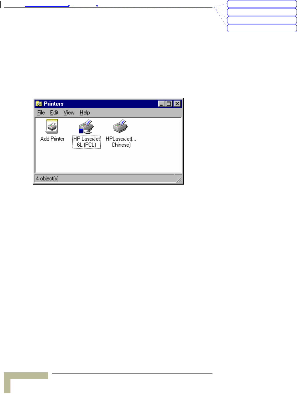
Configuring on Windows 95/98
Platforms
After installing the software (see Chapter 2), you need to configure your
printer to be able to operate the printer connected to the device's printer
port (the printer server). On a Windows 95/98 platform, open the
Printers window in the My Computer menu:
Now, yon can configure the print server of this product:
1. Find out the corresponding icon of your server printer, for example,
the HP LaserJet 6L. Click the mouse’s right button on that icon,
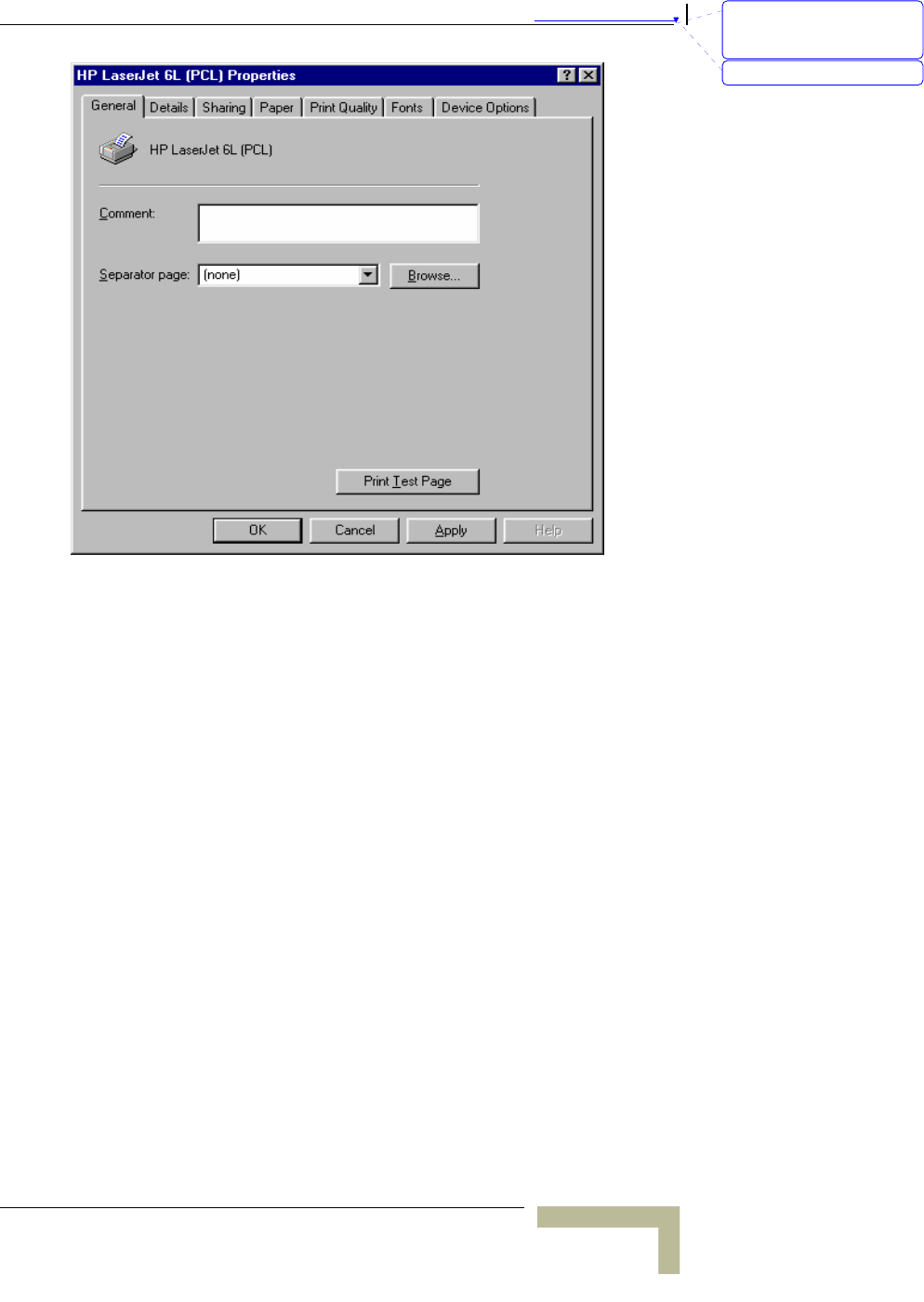
and then select the Properties item:
刪除: C
刪除: A
刪除: 802.1x Setting
刪除: Print Server
錯誤! 尚未定義樣式。
Wireless Networking Gateway System Manual
A
-3
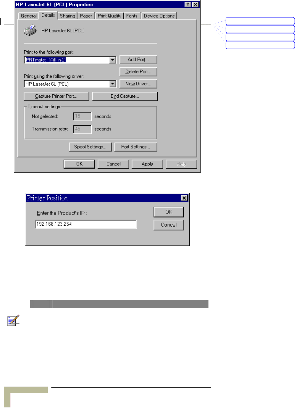
2. Click the Details item:
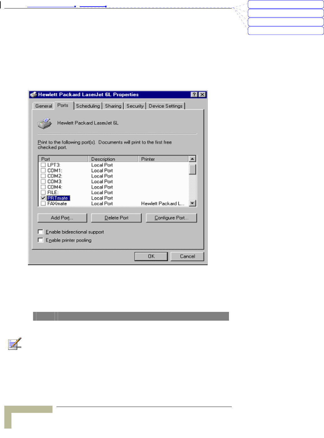
3. Choose the “PRTmate: (All-in-1)” from the list attached at the
Print To item. Be sure that the Printer Driver item is configured to
the correct driver of your server printer.
刪除: Set TCP/IP Protocol
for Working with NAT
Router
刪除: Wizard
Appendix 錯誤! 尚未定義樣式。 - Print Server
Print Server
A
-4
4. Click on the button of Port Settings:
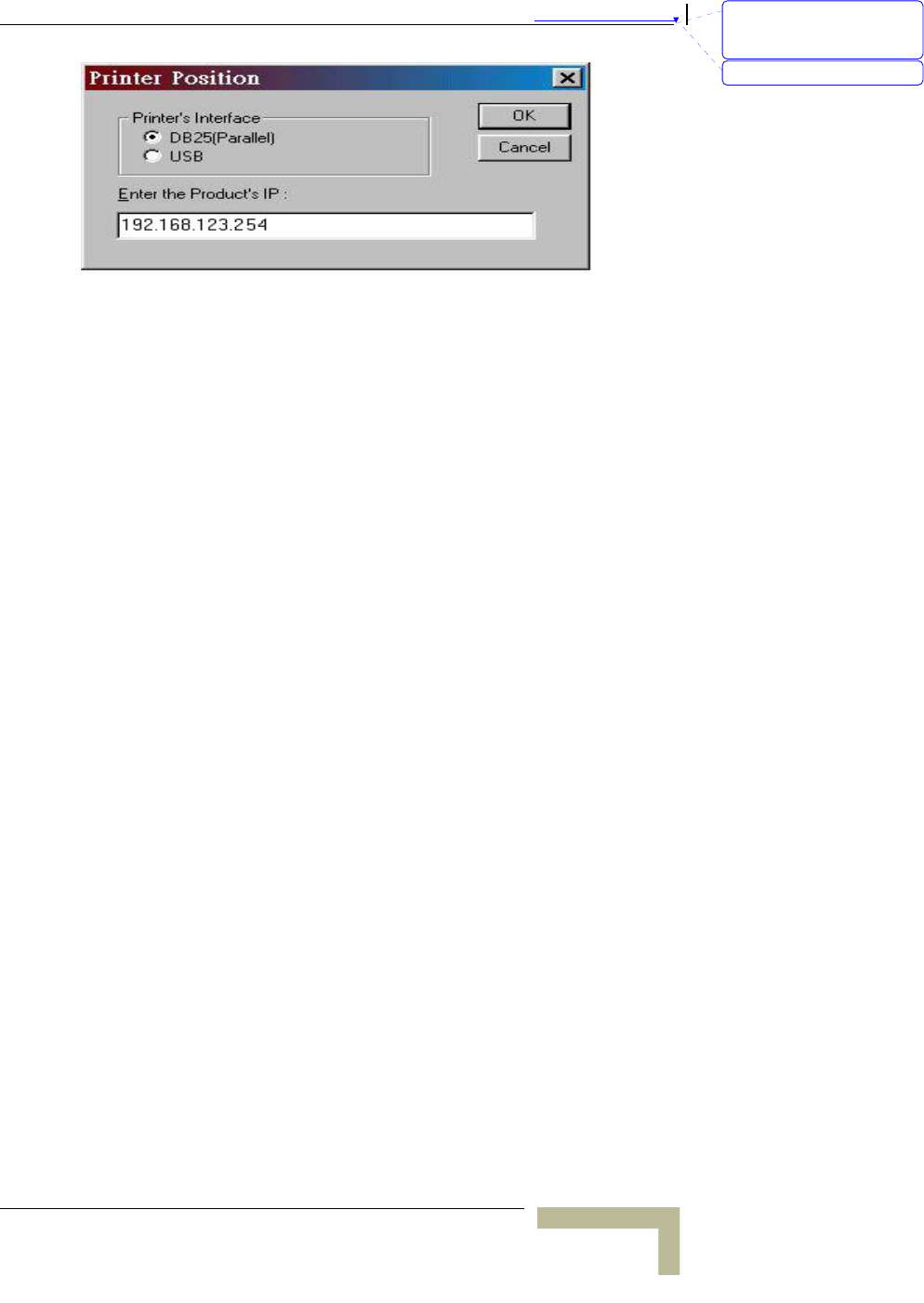
5. Types in the IP address of this product and then click the OK
button.
6. Make sure that all settings mentioned above are correct and
then click the OK button.
NOTE
If the router has USB and Parallel port at the same time, Please be careful to setup.
Use USB to print
Queue Name: lp
刪除: C
刪除: A
刪除: 802.1x Setting
刪除: Print Server
錯誤! 尚未定義樣式。
Wireless Networking Gateway System Manual
A
-5
刪除: Set TCP/IP Protocol
for Working with NAT
Router
刪除: Wizard
Appendix 錯誤! 尚未定義樣式。 - Print Server
Print Server
A
-6
Configuring on Windows NT
Platforms
The configuration procedure for a Windows NT platform is similar to
that of Windows 95/98 except the screen of printer Properties:
Compared to the procedure in last section, the selection of Details is
equivalent to the selection of Ports, and Port Settings is equivalent to
Configure Port.
NOTE
If the router has USB and Parallel port at the same time, Please be careful to setup.
Use Parallel to print
Queue Name: lp
Use USB to print
Queue Name: lpUSB0
刪除: C
刪除: A
刪除: 802.1x Setting
刪除: Print Server

錯誤! 尚未定義樣式。
Wireless Networking Gateway System Manual
A
-7
刪除: Set TCP/IP Protocol
for Working with NAT
Router
刪除: Wizard
Appendix 錯誤! 尚未定義樣式。 - Print Server
Print Server
A
-8
Configuring on Windows 2000 and XP
Platforms
Windows 2000 and XP have built-in LPR client, users could utilize this
feature to Print.
You have to install your Printer Driver on LPT1 or other ports
before you preceded the following sequence.
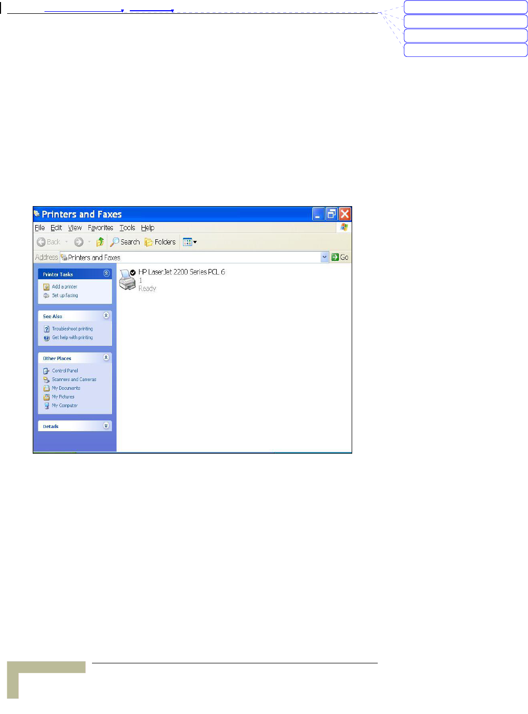
1. Open Printers and Faxes.
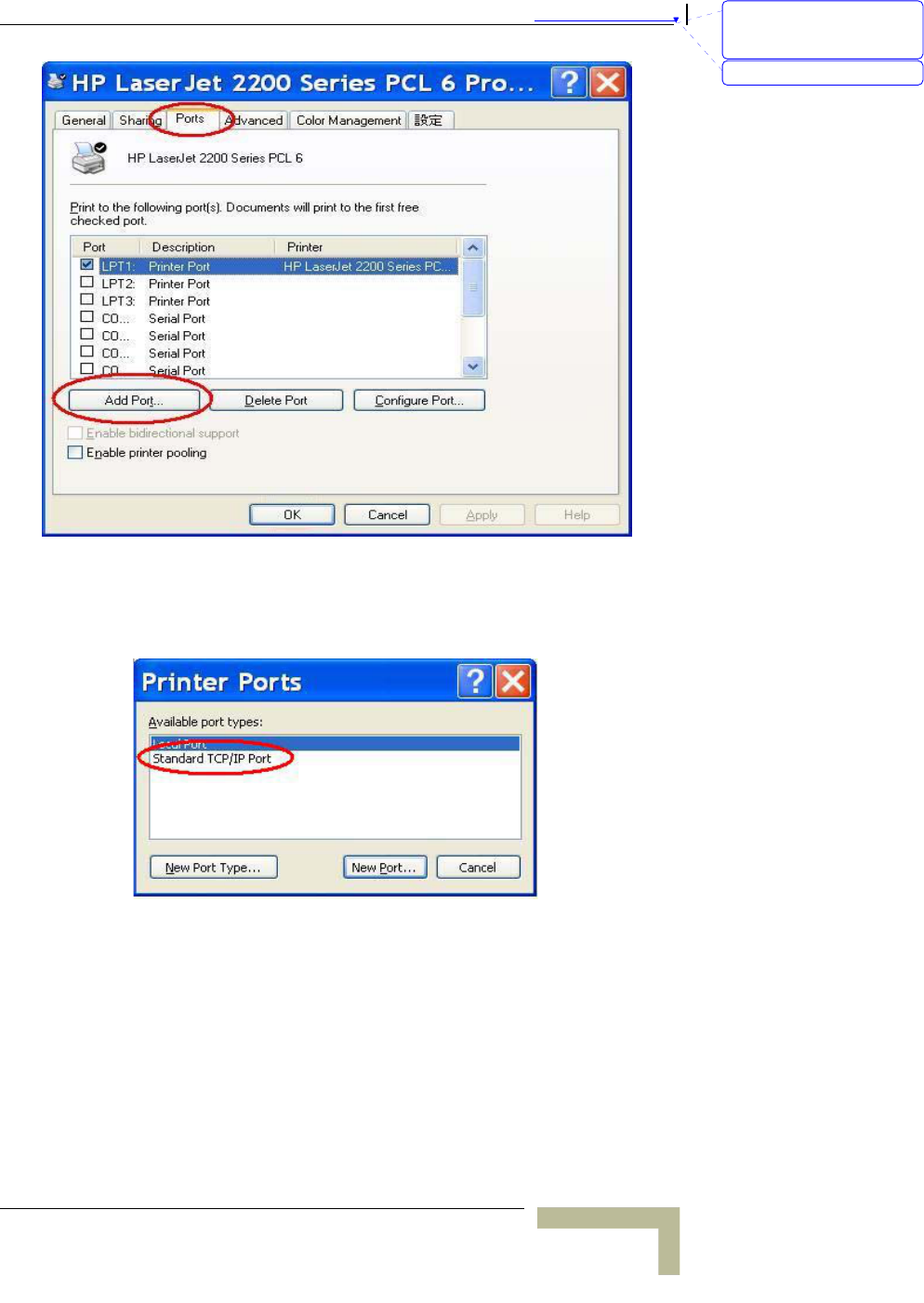
2. Select “Ports” page, Click “Add Port…”
刪除: C
刪除: A
刪除: 802.1x Setting
刪除: Print Server
錯誤! 尚未定義樣式。
Wireless Networking Gateway System Manual
A
-9
3. Select “Standard TCP/IP Port”, and then click “New Port…”
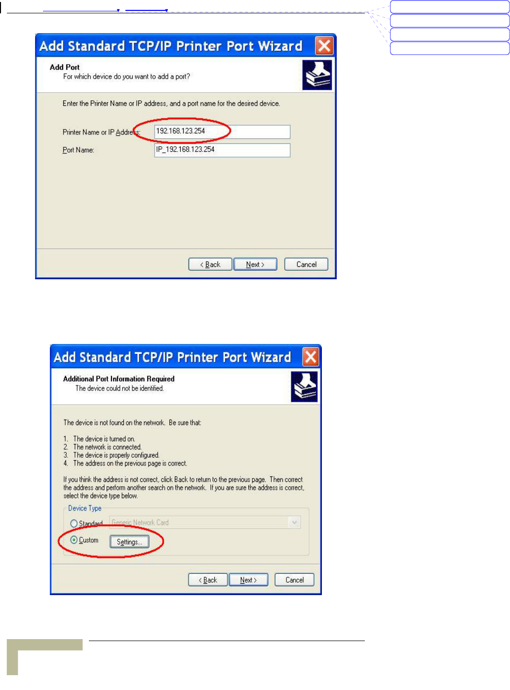
4. Click Next and then provide the following information:
5. Type the address of a server providing LPD that is our NAT
device: 192.168.123.254
刪除: Set TCP/IP Protocol
for Working with NAT
Router
刪除: Wizard
Appendix 錯誤! 尚未定義樣式。 - Print Server
Print Server
A
-10
6. Select Custom, and then click “Settings…”
刪除: C
刪除: A
刪除: 802.1x Setting
刪除: Print Server
錯誤! 尚未定義樣式。
Wireless Networking Gateway System Manual
A
-11
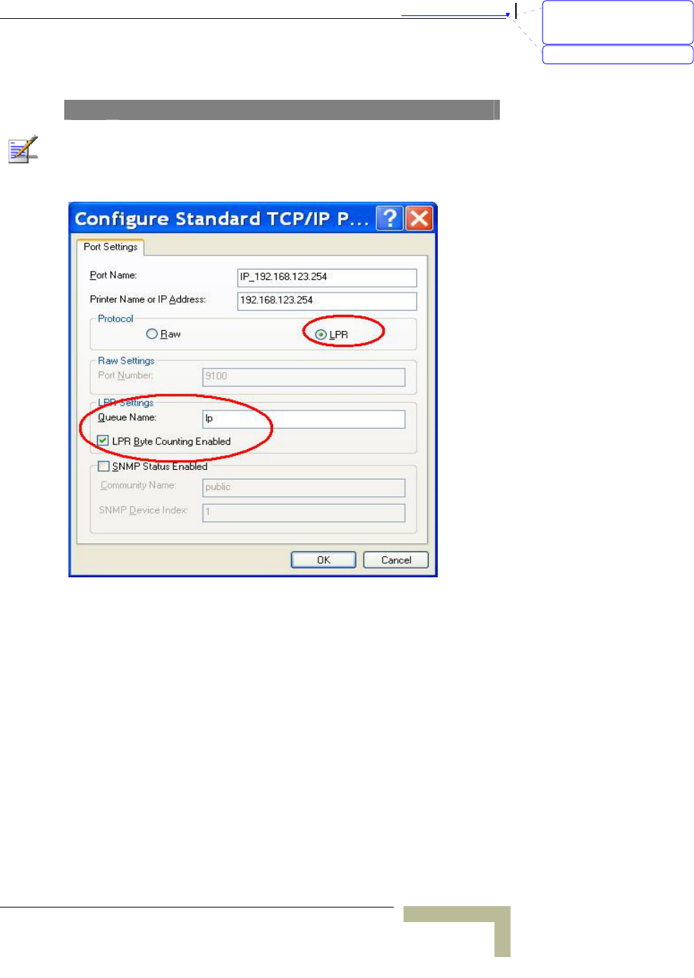
7. Select “LPR”; type ” lp“ lowercase letter in “Queue Name:” and
enable “LPR Byte Counting Enabled”.
NOTE
If the router has USB and Parallel port at the same time, Please be careful to setup.
Use USB to print
Queue Name: lp
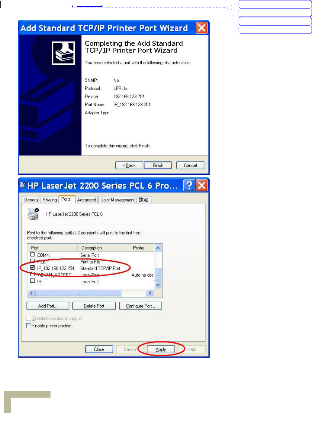
8. Apply your settings
刪除: Set TCP/IP Protocol
for Working with NAT
Router
刪除: Wizard
Appendix 錯誤! 尚未定義樣式。 - Print Server
Print Server
A
-12
刪除: C
刪除: A
刪除: 802.1x Setting
刪除: Print Server
錯誤! 尚未定義樣式。
Wireless Networking Gateway System Manual
A
-13
Configuring on Apple PC
TBD – is this necessary? It doesn't specify that the printer server is
supported by MAC.
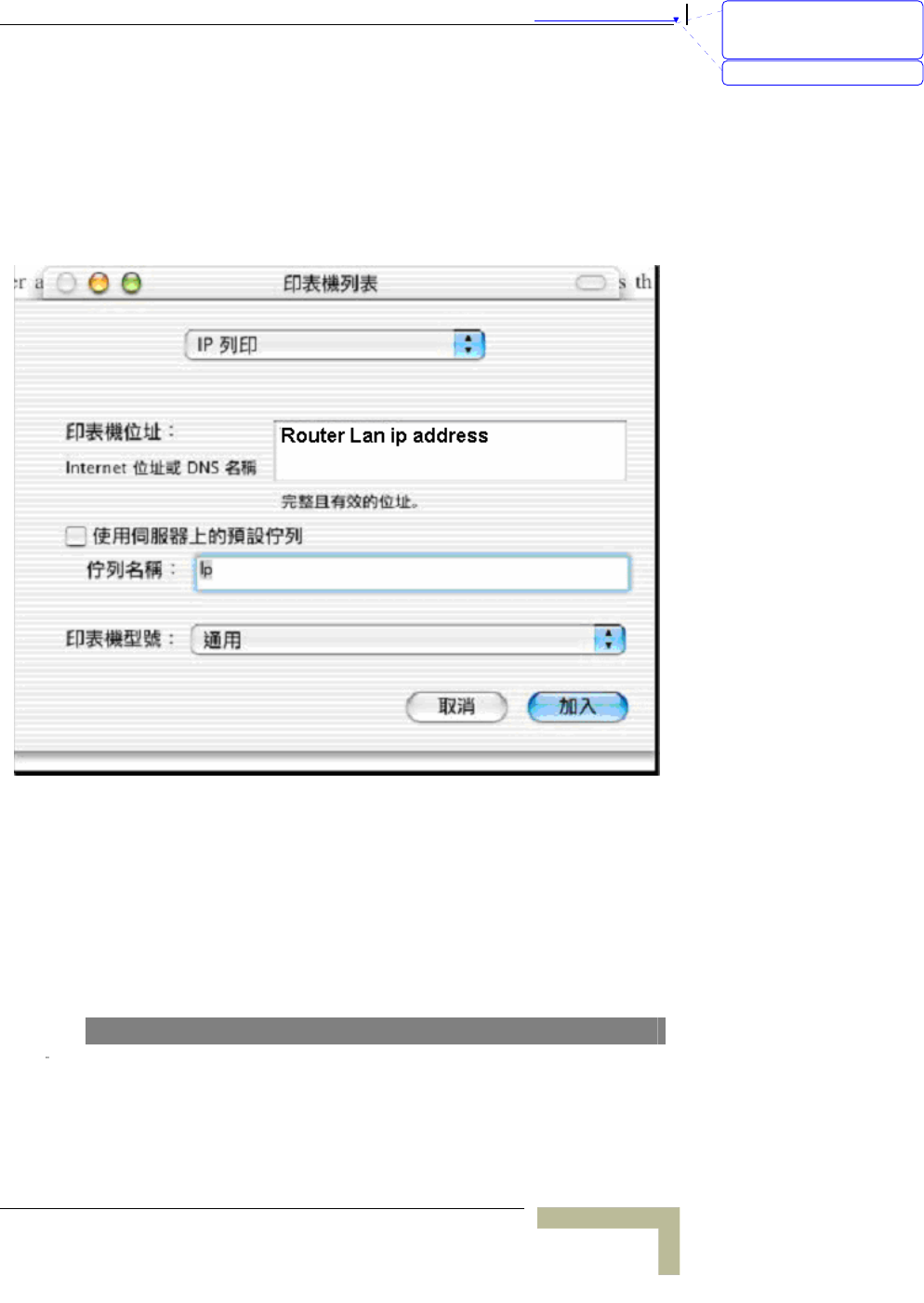
1. First, go to Printer center (Printer list) and add printer
2. Choose IP print and setup printer IP address (router LAN IP
address).
3. Disable “Default Queue of Server.” And fill in ‘ lp ‘ in Queue
name item.
4. Printer type: Choose “General”.
NOTE
刪除: Set TCP/IP Protocol
for Working with NAT
Router
刪除: Wizard

Appendix 錯誤! 尚未定義樣式。 - Print Server
Print Server
A
-14
If the router has USB and Parallel port at the same time, Please be careful to setup.
Use Parallel to print
Queue Name: lp
Use USB to print
Queue Name: lpUSB0
刪除: C
刪除: A
刪除: 802.1x Setting
刪除: Print Server

錯誤! 尚未定義樣式。
Wireless Networking Gateway System Manual
A
-15
TBD – what about UNIX? Delete.
刪除: Set TCP/IP Protocol
for Working with NAT
Router
刪除: Wizard

B
Appendix B - TCP/IP
Configuration for Windows 95/98
TBD – what about Windows NT, 2000, XP, UNIX?
This section introduces you how to install TCP/IP protocol into your
personal computer. And suppose you have been successfully installed
one network card on your personal computer. If not, please refer to your
network card manual. Moreover, the Section B.2 tells you how to set
TCP/IP values for working with this NAT Router correctly.
Appendix 錯誤! 尚未定義樣式。 - TCP/IP Configuration for Windows 95/98
TCP/IP Configuration for Windows 95/98
B-2
Installing TCP/IP Protocol on Your PC
1. Click Start button and choose Settings, then click Control Panel.
2. Double click Network icon and select Configuration tab in the
Network window.
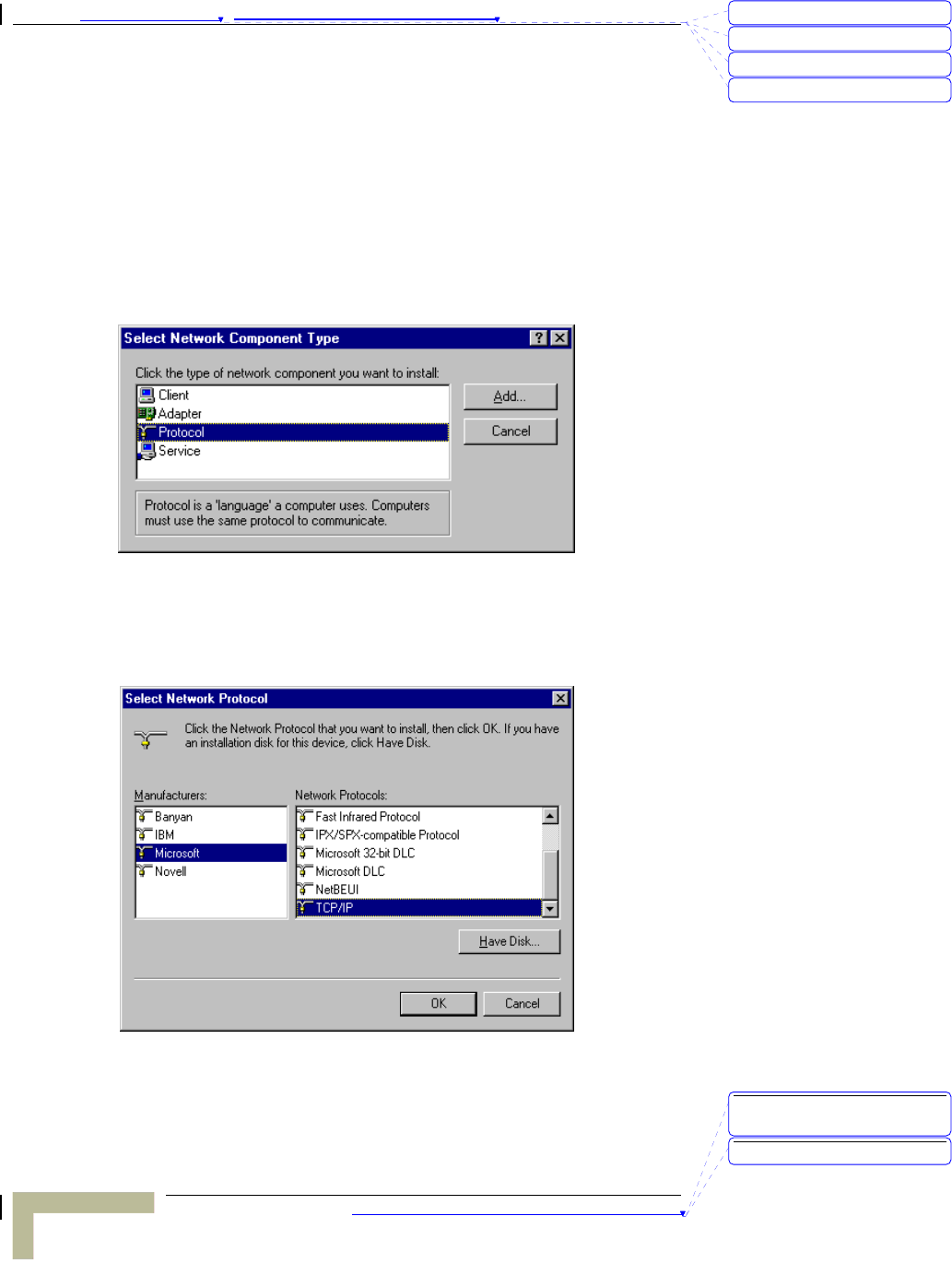
3. Click Add button to add network component into your PC.
4. Double click Protocol to add TCP/IP protocol.
5. Select Microsoft item in the manufactures list. And choose
TCP/IP in the Network Protocols. Click OK button to return to
Network window.
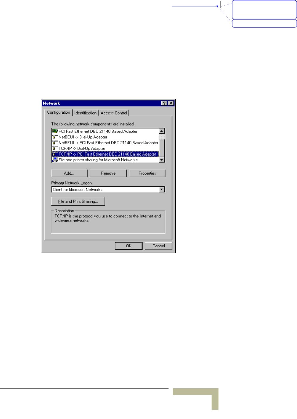
6. The TCP/IP protocol shall be listed in the Network window. Click
OK to complete the install procedure and restart your PC to enable
the TCP/IP protocol.
刪除: C
刪除: A
刪除: 802.1x Setting
刪除: Print Server
刪除: TCP/IP Configuration
for Windows 95/98
刪除: Print Server
錯誤! 尚未定義樣式。
Wireless Networking Gateway System Manual
B-3
Set TCP/IP Protocol for Working with
NAT Router
1. Click Start button and choose Settings, then click Control Panel.
2. Double click Network icon. Select the TCP/IP line that has been
associated to your network card in the Configuration tab of the
Network window.
3. Click Properties button to set the TCP/IP protocol for this NAT
Router.
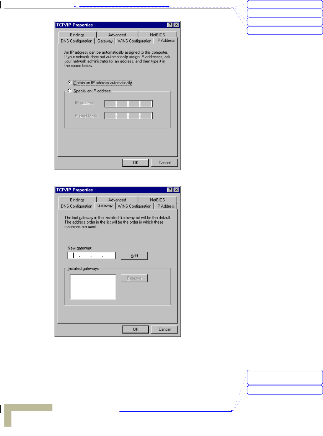
4. Now, you have two setting methods:
¾ Select Obtain an IP address automatically in the IP Address
tab.
刪除: Set TCP/IP Protocol
for Working with NAT
Router
刪除: Wizard
Appendix 錯誤! 尚未定義樣式。 - TCP/IP Configuration for Windows 95/98
TCP/IP Configuration for Windows 95/98
B-4
¾ Don’t input any value in the Gateway tab.
刪除: C
刪除: A
刪除: 802.1x Setting
刪除: Print Server
刪除: TCP/IP Configuration
for Windows 95/98
刪除: Print Server
錯誤! 尚未定義樣式。
Wireless Networking Gateway System Manual
B-5
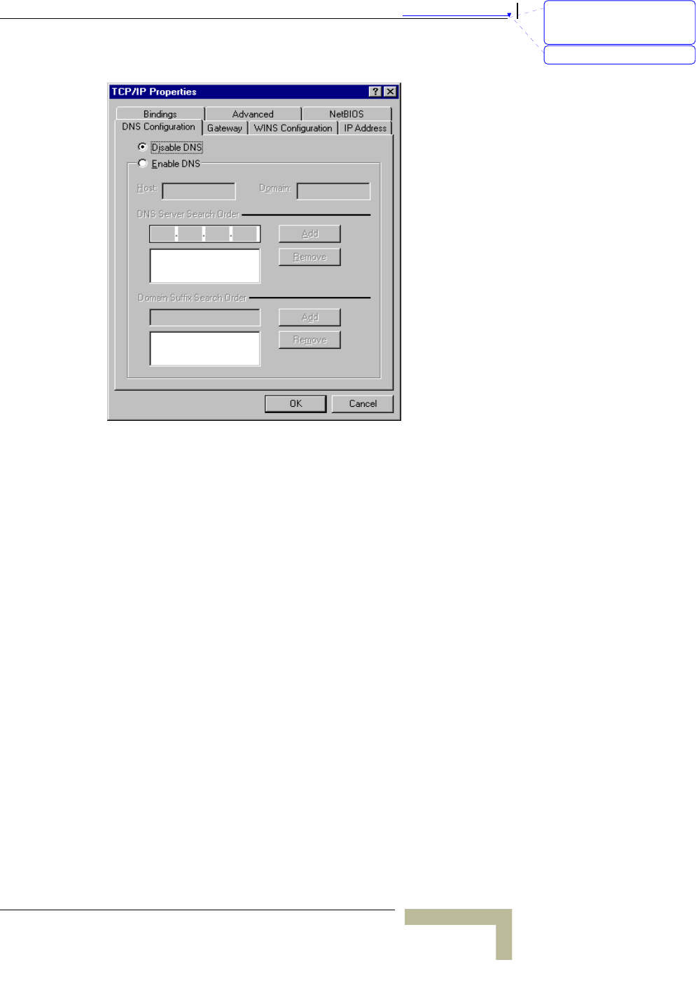
¾ Choose Disable DNS in the DNS Configuration tab.
5. Configure IP manually
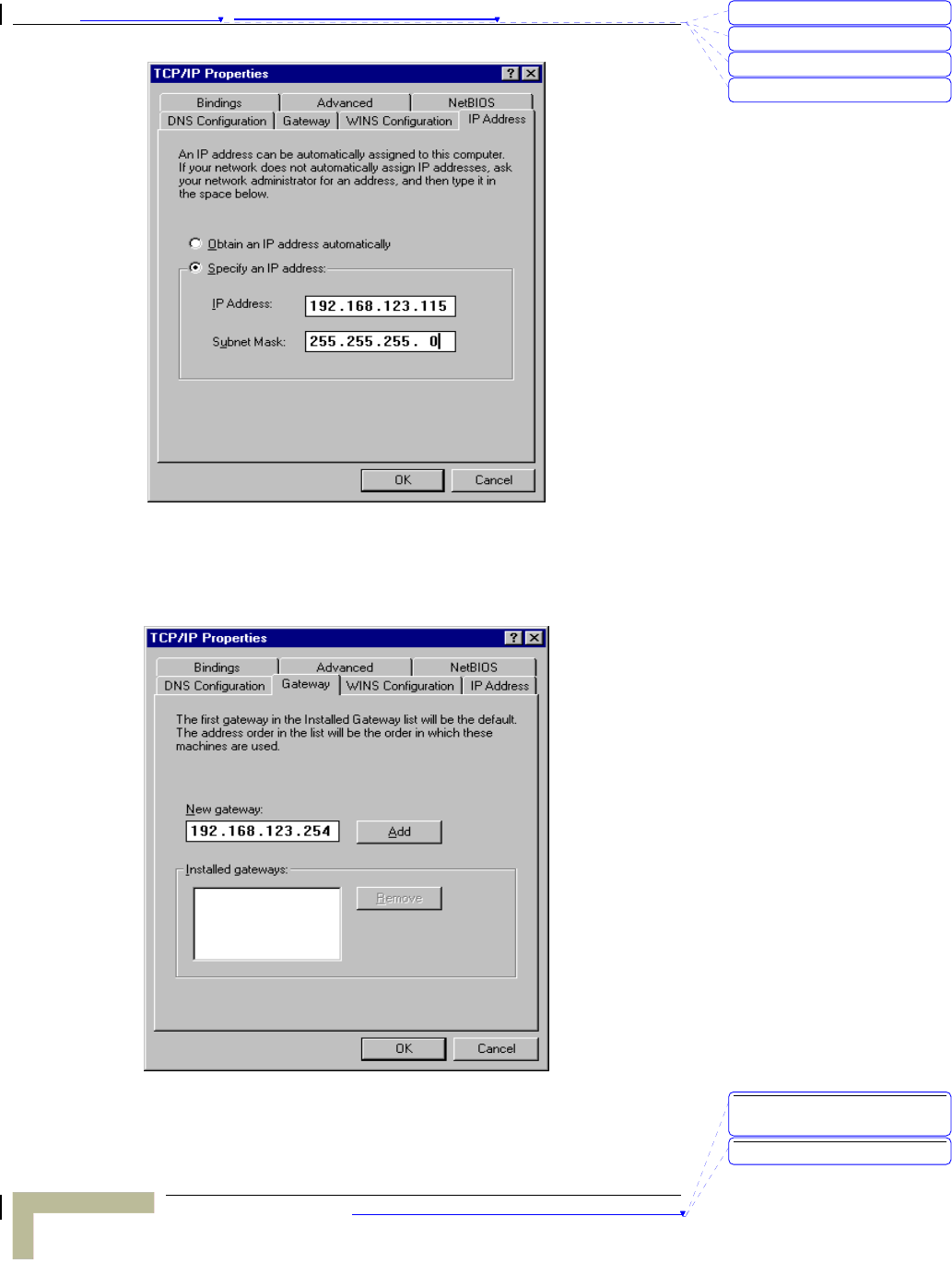
¾ Select Specify an IP address in the IP Address tab. The
default IP address of this product is 192.168.123.254. So
please use 192.168.123.xxx (xxx is a number between 1 and
253) for IP Address field and 255.255.255.0 for Subnet Mask
field.
刪除: Set TCP/IP Protocol
for Working with NAT
Router
刪除: Wizard
Appendix 錯誤! 尚未定義樣式。 - TCP/IP Configuration for Windows 95/98
TCP/IP Configuration for Windows 95/98
B-6
¾ In the Gateway tab, add the IP address of this product
(default IP is 192.168.123.254) in the New gateway field and
click Add button.
刪除: C
刪除: A
刪除: 802.1x Setting
刪除: Print Server
刪除: TCP/IP Configuration
for Windows 95/98
刪除: Print Server
錯誤! 尚未定義樣式。
Wireless Networking Gateway System Manual
B-7
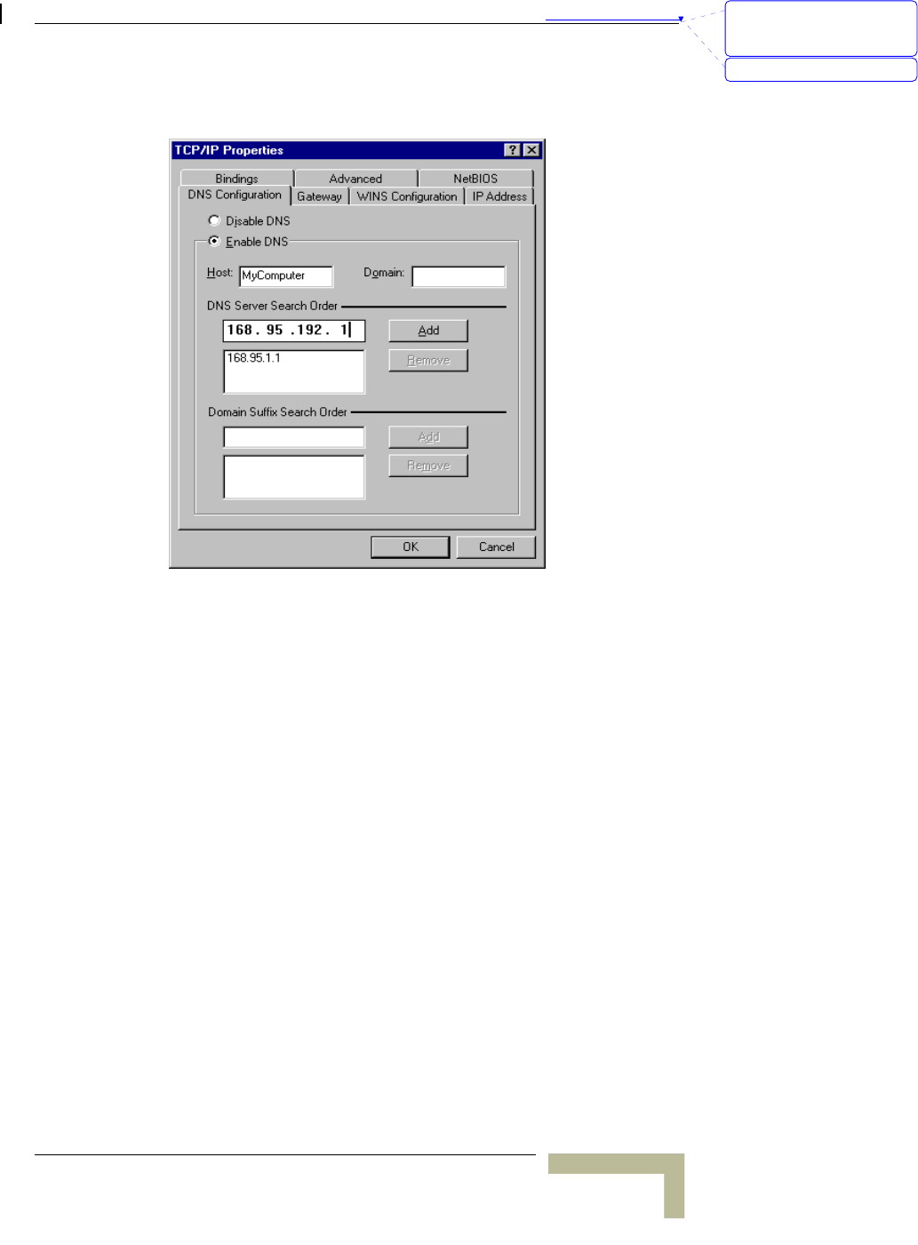
¾ In the DNS Configuration tab, add the DNS values which are
provided by the ISP into DNS Server Search Order field and
click Add button.
刪除: Set TCP/IP Protocol
for Working with NAT
Router
刪除: Wizard

C
Appendix C - 802.1x Setting
TBD – check this section on a lab compuer.
Appendix 錯誤! 尚未定義樣式。 - 802.1x Setting
802.1x Setting
C-2
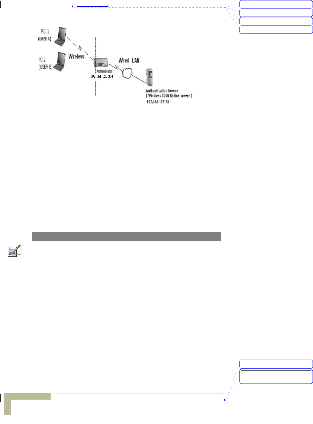
Figure 1: Testing Environment (Use Windows 2000 Radius Server)
Equipment Details
¾ PC1:
Microsoft Windows XP Professional without Service Pack 1.
D-Link DWL-650+ wireless LAN adapter
Driver version: 3.0.5.0 (Driver date: 03.05.2003)
¾ PC2:
Microsoft Windows XP Professional with Service Pack 1a.
Z-Com XI-725 wireless LAN USB adapter
Driver version: 1.7.29.0 (Driver date: 10.20.2001)
¾ Authentication Server: Windows 2000 RADIUS server with
Service Pack 3 and HotFix Q313664.
NOTE
Windows 2000 RADIUS server only supports PEAP upgraded to service pack 3 and
HotFix Q313664 (You can receive additional information from
http://support.microsoft.com/default.aspx?scid=kb; en-us;313664)
DUT
¾ Configuration:
Enable DHCP server.
WAN setting: static IP address.
LAN IP address: 192.168.123.254/24.
Set RADIUS server IP.
Set RADIUS server shared key.
Configure WEP key and 802.1X setting.
刪除: C
刪除: A
刪除: 802.1x Setting
刪除: Print Server
刪除: 802.1x Setting
刪除: TCP/IP Configuration
for Windows 95/98

錯誤! 尚未定義樣式。
Wireless Networking Gateway System Manual
C-3
The following test uses the inbuilt 802.1X authentication method such
as, EAP_TLS, PEAP_CHAPv2 (Windows XP with SP1 only), and
PEAP_TLS (Windows XP with SP1 only) using the Smart Card or other
Certificate of the Windows XP Professional.
DUT and Windows 2000 Radius Server Setup
¾ Setup Windows 2000 RADIUS Server
Change authentication method to MD5_Challenge or using
smart card or other certificate on RADIUS server according
to the test condition.
¾ Setup DUT
1. Enable the 802.1X (check the “Enable checkbox“).
2. Enter the RADIUS server IP.
3. Enter the shared key. (The key shared by the RADIUS
server and DUT).
4. Change 802.1X encryption key length to fit the variable
test condition.
¾ Setup Network adapter on PC
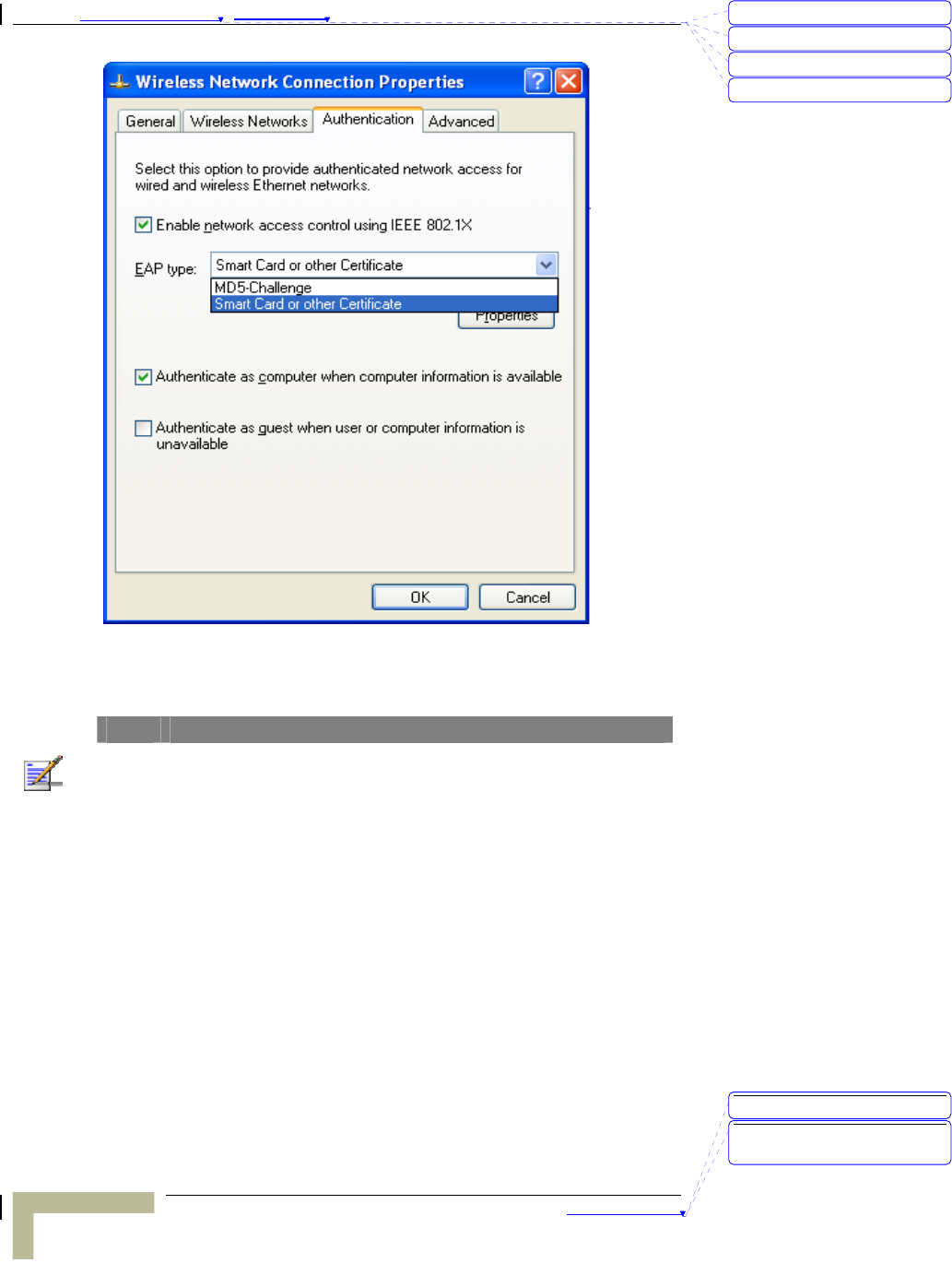
1. Select the IEEE802.1X as the authentication method.
刪除: Set TCP/IP Protocol
for Working with NAT
Router
刪除: Wizard
Appendix 錯誤! 尚未定義樣式。 - 802.1x Setting
802.1x Setting
C-4
Figure 61: Enable IEEE 802.1X Access Control
NOTE
Figure 61 is a setting picture of Windows XP without service pack 1. If users
upgrade to service pack 1, they will not see MD5-Challenge from EAP type
list, but they will receive a new Protected EAP (PEAP) option.
2. Select MD5-Challenge or Smart Card or other Certificate
as the EAP type
3. If use smart card or the certificate is selected as the EAP
type, select to use a certificate on this computer.
刪除: C
刪除: A
刪除: 802.1x Setting
刪除: Print Server
刪除: 802.1x Setting
刪除: TCP/IP Configuration
for Windows 95/98
錯誤! 尚未定義樣式。
Wireless Networking Gateway System Manual
C-5
Figure 62: Smart Card or Certificate Properties
4. Change EAP type to fit the variable test condition.
Windows 2000 RADIUS server Authentication testing:
¾ DUT authenticate PC1 using certificate. (PC2 follows the
same test procedures.)
5. Download and install the certificate on PC1. (Fig 4)
6. PC1 choose the SSID of DUT as the Access Point.
7. Set authentication type of wireless client and RADIUS
server both to EAP_TLS.
8. Disable the wireless connection and enable again.
9. The DUT will send the user's certificate to the RADIUS
server, and then
10. send the message of authentication result to PC1. (Fig 5)
11. Windows XP will prompt that the authentication process
is success or fail and end the authentication procedure.
(Fig 6)
12. Terminate the test steps when PC1 get dynamic IP and
PING remote host successfully.
刪除: Set TCP/IP Protocol
for Working with NAT
Router
刪除: Wizard
Appendix 錯誤! 尚未定義樣式。 - 802.1x Setting
802.1x Setting
C-6
Figure 4: Certificate information on PC1
Figure 5: Authenticating
刪除: C
刪除: A
刪除: 802.1x Setting
刪除: Print Server
刪除: 802.1x Setting
刪除: TCP/IP Configuration
for Windows 95/98
錯誤! 尚未定義樣式。
Wireless Networking Gateway System Manual
C-7
Figure 6: Authentication success
¾ DUT authenticate PC2 using PEAP-TLS.
1. PC2 choose the SSID of DUT as the Access Point.
2. Set authentication type of wireless client and RADIUS
server both to PEAP_TLS.
3. Disable the wireless connection and enable again.
4. The DUT will send the user's certificate to the RADIUS
server, and then send the message of authentication
result to PC2.
5. Windows XP will prompt that the authentication process
is success or fail and end the authentication procedure.
6. Terminate the test steps when PC2 get dynamic IP and
PING remote host successfully.
Support Type: The router supports the types of 802.1x
Authentication:
PEAP-CHAPv2 and PEAP-TLS.
NOTE
PC1 is on Windows XP platform without Service Pack 1.
PC2 is on Windows XP platform with Service Pack 1a.
PEAP is supported on Windows XP with Service Pack 1 only.
Windows XP with Service Pack 1 allows 802.1x authentication only when data
encryption function is enable.
刪除: Set TCP/IP Protocol
for Working with NAT
Router
刪除: Wizard

Federal Communication Commission Interference Statement
This equipment has been tested and found to comply with the limits for a Class B digital device, pursuant
to Part 15 of the FCC Rules. These limits are designed to provide reasonable protection against harmful
interference in a residential installation. This equipment generates, uses and can radiate radio frequency
energy and, if not installed and used in accordance with the instructions, may cause harmful interference
to radio communications. However, there is no guarantee that interference will not occur in a particular
installation. If this equipment does cause harmful interference to radio or television reception, which can
be determined by turning the equipment off and on, the user is encouraged to try to correct the
interference by one of the following measures:
• Reorient or relocate the receiving antenna.
• Increase the separation between the equipment and receiver.
• Connect the equipment into an outlet on a circuit different from that to which the receiver is
connected.
• Consult the dealer or an experienced radio/TV technician for help.
This device complies with Part 15 of the FCC Rules. Operation is subject to the following two
conditions: (1) This device may not cause harmful interference, and (2) this device must accept
any interference received, including interference that may cause undesired operation.
Caution:. Any changes or modifications not expressly approved by the party responsible for compliance
could void the user's authority to operate this equipment.
RF Exposure Warning: This equipment complies with FCC radiation exposure limits set forth for an
uncontrolled environment. This equipment must be installed and operated with a minimum distance
of 20 centimeters between the radiator and your body. This device and its antenna must not be co-located or
operating in conjunction with any other antenna or transmitter.