Advance Security TR09AM Car Alarm Transceiver User Manual
Advance Security Inc Car Alarm Transceiver
UserManual.wiki
>
Advance Security
>
TR09AM User Manual
User Manual
Navigation menu
Upload a User Manual
Namespaces
Wiki Guide
HTML
PDF
Info
Views
User Manual
Discussion / Help
Navigation
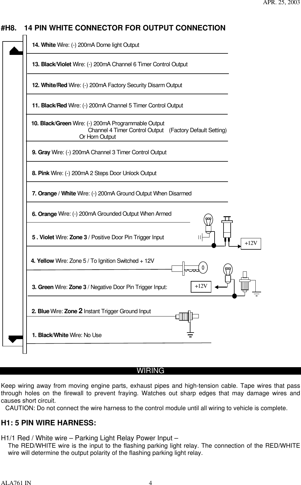
![APR. 25, 2003 ALA761 IN 9 ROGRAMMING A. PROGRAMMING TRANSMITTER: PROGRAMMING THE REMOTE TRANSMITTER Note: This mode will only retain the last 4 remote transmitters programmed. If the transmitter memory is exceeded, the security system will start deleting transmitters from memory in chronological order. Enter: 1. Turn the Ignition 'switch ‘OFF/ON’ 3 TIMES and stay in ON position. Within 15 seconds. 2. Push the Valet switch 3 times and hold it until a long chirp is hearing then release the valet switch. You are now in the Transmitter programming mode. Program: 1. Press button on one of the transmitter until the siren responds with a confirming chirp the first transmitter is now programmed. 2. Press button on the second transmitter until the siren responds with a confirming chirp, the second transmitter is now programmed. 3. Apply the same procedure to program 3rd and 4th. Exit: Turn Ignition to 'OFF' position, or leave it for 15 seconds. A 3 long chirps & 3 parking light flashes to confirm exit. B. FEATURES PROGRAMMING: ALARM FEATURE “I” PRORAMMING: 1. Turn the Ignition 'switch ‘ON/OFF’ 3 TIMES and stay in OFF position. 2. Push the Valet switch 2 times and hold it until one chirp with a long chirp is hearing then release the valet switch. You are now in the Alarm feature ‘I’ programming mode. 3. Press and release the transmitter button ‘A’ corresponding to the feature ‘A’ you want to program. a. The siren chirps and LED pause will indicate previously setting. b. The factory default settings is always [1] LED flash, [1] chirp. 4 Depress the transmitter button ‘A’ again to change the feature. Simple keep re-depressing the transmitter button ‘A’ again until the module advances to your desired setting. a. In this case, Press button ‘A’ again, the module would advance to [2] LED flash, [2] chirps. b. Press button ‘A’ again, the module would advance to [3] LED flash, [3] chirps etc. 5. Depress the transmitter button ‘B’ corresponding to the feature ‘B’ you wants to program. For example: To program the arming mode form “Active arming” to “Passive Arming without Passive Door Locking”, After “Arming mode” program, the next program is “Rearm on/off” .………. 1 Turn the Ignition 'switch ‘ON/OFF’ 3 TIMES and stay in OFF position. 2 Push the Valet switch 2 times and hold it until a chirp with a long chirp is hearing then release the valet switch. 3 Press and release the transmitter button corresponding to the feature ‘Arming mode’ you wants to program. [1] LED flash, [1] chirp to indicate your are in features “Active Arming”. 4 Depress the transmitter button twice to change the feature. [3] LED flash, [3] chirps to indicate your are in features “Passive Arming without Passive Door Locking ”. 5 Depress the transmitter button corresponding to the features ”Rearm on/off”’ you want to program…….. Press Transmitter Button One Chirp / LED one pulse Factory Default Setting Two Chirps / LED two pulse Three Chirps / LED three pulse Four Chirps / LED four pulse 1 All chirps on Siren chirp on only Horn chirp on only All chirps off 2 Active arming Passive arming without passive door locking Passive arming with passive door locking. 3 Automatic Rearm on Automatic Rearm off 4 3 seconds Delay Door Ajar error chirp 30 seconds Delay Door Ajar error chirp.](https://usermanual.wiki/Advance-Security/TR09AM/User-Guide-335255-Page-9.png)
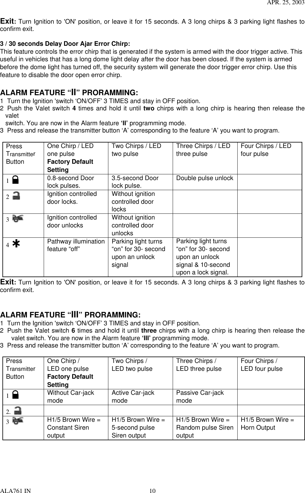
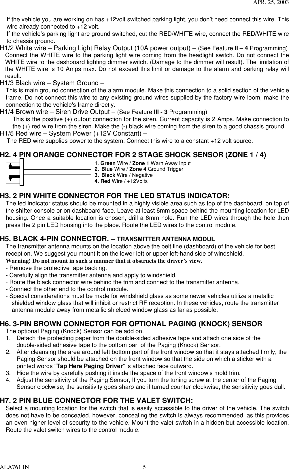
![APR. 25, 2003 ALA761 IN 12 Channel 3 (4/ 5 / 6) Timer Control Output Programming Enter: 1. Turn the Ignition 'switch ‘ON/OFF’ 3 TIMES and stay in OFF position. 2. Push the Valet switch 8 times and hold it until four chirps with a long chirp is hearing then release the valet switch. You are now in the Alarm feature ‘IV’ programming mode. Timer Program: 1-a. Press and release the transmitter button 4 times, [4] LED flash, [4] siren/horn chirp to indicate your are in features “Channel 3 Timer Programming mode”. 1-b. Press and release the transmitter button 4 times, [4] LED flash, [4] siren/horn chirp to indicate your are in features “Channel 4 Timer Programming mode”. 1-c. Press and release the transmitter button 4 times, [4] LED flash, [4] siren/horn chirp to indicate your are in features “Channel 5 Timer Programming mode”. 1-d. Press and release the transmitter button 4 times, [4] LED flash, [4] siren/horn chirp to indicate your are in features “Channel 6 Timer Programming mode”. 2. Press and hold the valet switch, the timer will immediately start. 3. When the desired interval has passed, release the valet switch. 1 long chirp for confirmation. (Set to any interval between 1 second and 2 minutes) Note 1: If your built-in timer controls window/sunroof closure in your car DO NOT change the timer setting! This requires installer-only programming. Changing the value will adversely effect operation and may cause damage. Note 2: Momentary output = The momentary output selection will output a negative signal from the Channel 3 (4/5/6) output immediately when the channel 3 (4/5/6) button is pressed and will continue until the button is release. Latched output = The latched output selection will output a negative signal as soon as the Channel 3 (4/5/6) button is pressed and will continue until the button is pressed again. Latched output / reset with ignition = The latched / reset with ignition output selection operates just like the latched output but will reset or stop when the ignition is turned on. ALARM FEATURE “V” PRORAMMING: 1. Turn the Ignition 'switch ‘ON/OFF’ 3 TIMES and stay in OFF position. 2. Push the Valet switch 10 times and hold it until five chirps with a long chirp is hearing then release the valet switch. You are now in the Alarm feature ‘V’ programming mode. 3. Press and release the transmitter button ‘A’ corresponding to the feature ‘A’ you want to program. Press Transmitter Button One Chirp / LED one pulse Factory Default Setting Two Chirps / LED two pulse Three Chirps / LED three pulse Four Chirps / LED four pulse 1 Exit the programming mode. (3 long chirp & 3 parking light flashes to confirm this exit.) 2. Override Without Password Pin Code Override With Password Pin Code 3 “TEST” Mode for Zone 2 / instant trigger & Zone 3 / Door trigger “TEST” Mode for Zone 1 & Zone 4 (2 Stage Shock Sensor) 4 Panic with Ignition off Panic with Ignition on & off Panic with Ignition on & off. Panic with No time limit. Without Panic function. Exit: Press the button on the transmitter. A 3 long chirps & 3 parking light flashes to confirm exit. Password Pin Code Setup: Enter: 1. Turn the Ignition 'switch ‘ON/OFF’ 3 times and stay in OFF position.](https://usermanual.wiki/Advance-Security/TR09AM/User-Guide-335255-Page-12.png)
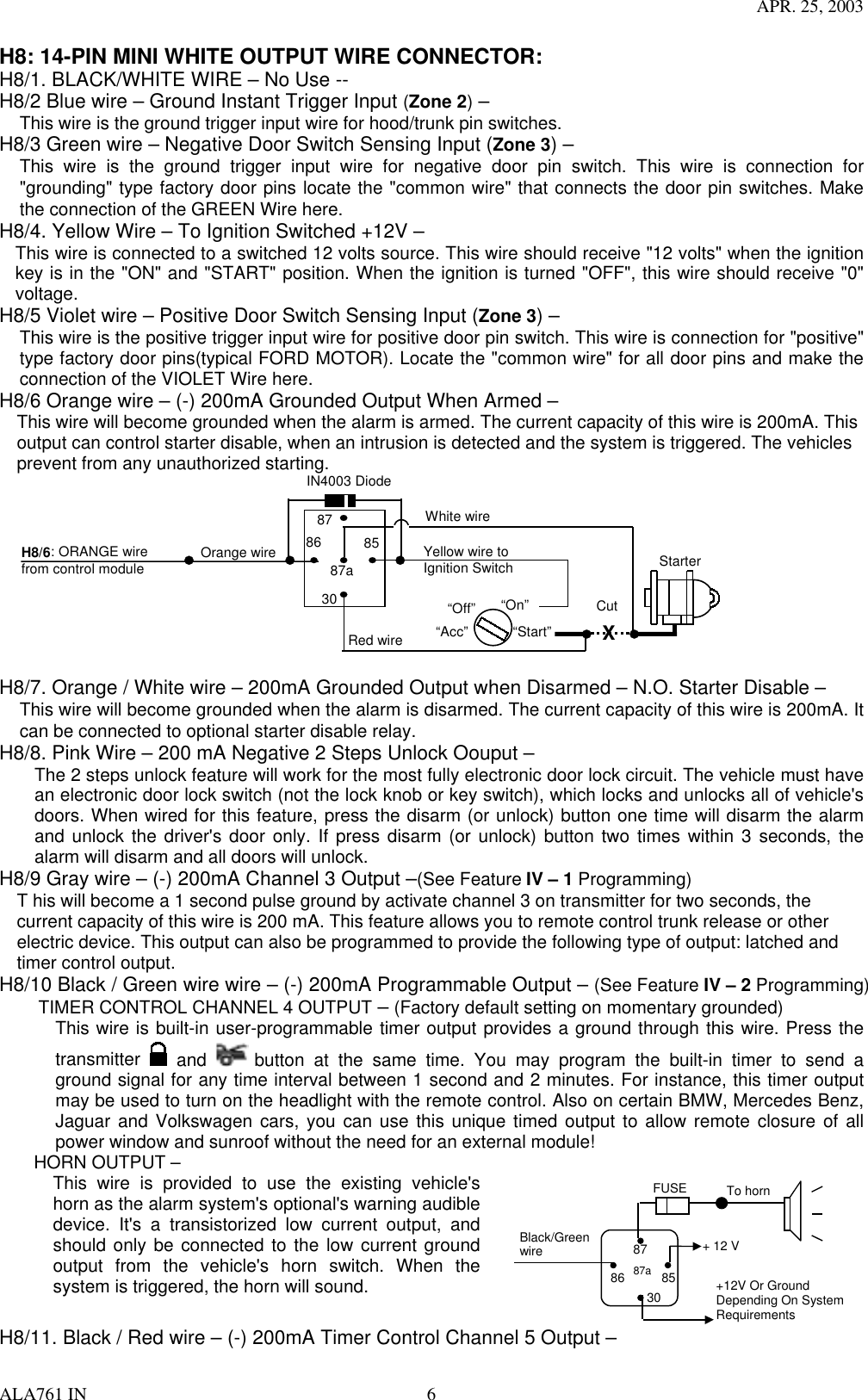
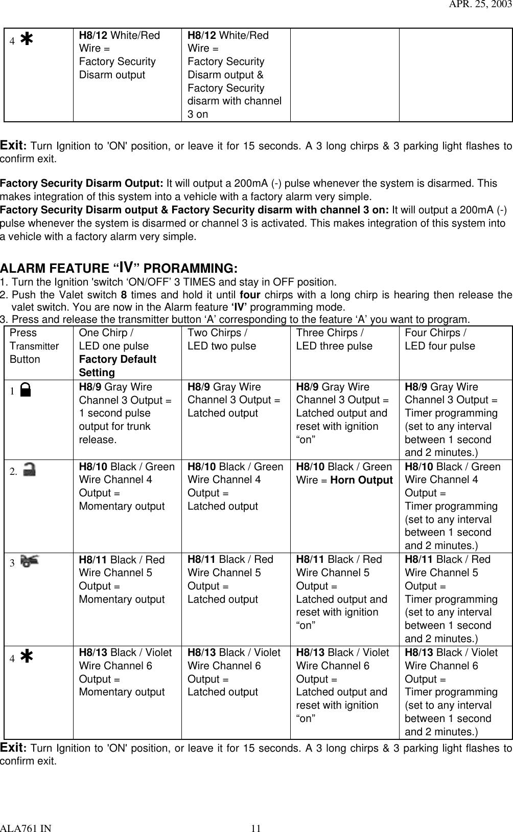
![APR. 25, 2003 ALA761 IN 13 2. Push the Valet switch 10 times and hold it until five chirps with a long chirp is hearing then release the valet switch. You are now in the Alarm feature ‘V’ programming mode. You can program or delete the password pin code as below: Program: 1. Press and release the transmitter button twice, [2] LED flash, [2] siren/horn chirp to indicate your are in features “Password Pin Code Programming mode”. 2. Within 5 seconds, begin to enter your chosen first 9ths digit by pressing and releasing the valet Switch from 1 – 9 times. 3. Within 15 seconds of the last entered 9ths digit, turn the Ignition switch to “ON” position. 4. Within 15 seconds, enter your chosen second 9ths digit by pressing and releasing the valet Switch from 1 – 9 times. 5. Finish by turning the ignition switch to “OFF” position. If the new password code was accepted, the unit would report back the newly entered code, by flashing the LED, first indicating the first digit code has been memorized, pause and then the second digit code. The unit will report the new code three times with a one-second’s pause between each code. Note: If 15 seconds of inactivity expire, or if the ignition switch is turned “ON” for more then 5 seconds during of above steps, the unit will revert back to the last successfully stored code. A [3] long chirps to confirm exit. Will revert back to the last successfully stored code Delete Password Pin Code / Override Without Password Pin Code (Factory default setting): Within 15 seconds, press and hold the transmitter button for 4 seconds. A one long chirps to confirm Deleted the Password Pin Code. Example: To program the Password Code 92, you would; Enter: 1. Turn the Ignition 'switch ‘ON/OFF’ 3 times and stay in OFF position. 2. Push the Valet switch 10 times and hold it until five chirps with a long chirp is hearing then release the valet switch. You are now in the Alarm feature ‘V’ programming mode. Program: 1. Press and release the transmitter button twice, [2] LED flash, [2] siren/horn chirp to indicate your are in features “Password pin code programming mode”. 2. Within 5 seconds, press and release the valet Switch 9 times. 3. Within 15 seconds of the last entered 9ths digit, Turn the Ignition Switch to “ON” position. 4. Within 15 seconds press the valet Switch twice. 5. Turn the Ignition Switch to “OFF’ position. You will note the LED flashing nine times, pause and then flash two times, pause. This pattern will be repeated three times indicating the new code (92) has been accepted and stored in memory. Exit: Press any button (except button) of the transmitter to exit the password pin set up mode. TEST MODE In this test mode, this system can test the Zone 2 (Instant ground trigger), the Zone 3 (Door trigger), and the Zone 1 & Zone 4 (2 stage shock sensor) sensitivity. The installer can save time to test the 2 stage shock sensor sensitivity and sensor without using the traditional arming/disarming procedures to test the sensors. Enter: 1. Turn the Ignition 'switch ‘ON/OFF’ 3 TIMES and stay in OFF position. 2. Push the Valet switch 10 times and hold it until five chirps with a long chirp is hearing then release the valet switch. You are now in the Alarm feature ‘V’ programming mode. a. Test the Zone 2 / Instant Ground Trigger & Zone 3 / Door Trigger: Press and release the transmitter button once. [1] LED flash, [1] siren/horn chirp to indicate your are in Zone 2 / instant ground trigger and Zone 3 / Door trigger test mode. Trigger sensor Siren chirps Zone 2 / Instant Ground trigger (H8/2 Blue wire) 2 Zone 3 / Door trigger (H8/3 Green or H8/5 Violet wire) 3 b. Test the Zone 1 & Zone 4 / Two Stage Shock Sensor (Connected to H2 4 Pin Plug): Press and release the transmitter button twice. [2] LED flash, [2] siren/horn chirps to indicate your are in the shock sensor (connected to H2 4 pin plug) test mode. 1. Activate the warn-away (first stage of the shock sensor / Zone 1), system will emit a short chirp. 2. Activate the full alarm (second stage of the shock sensor / Zone 4), system will emit a long chirp. 3. Continue to test the shock sensor until reach the proper sensitivity.](https://usermanual.wiki/Advance-Security/TR09AM/User-Guide-335255-Page-13.png)