Advance Security TR09AM Car Alarm Transceiver User Manual
Advance Security Inc Car Alarm Transceiver
User Manual
APR. 25, 2003
ALA761 IN 1
MODEL ALA761
REMOTE ENGINE STARTER
WITH ALARM SYSTEM
INSTALLATION MANUAL

APR. 25, 2003
ALA761 IN 2
TABLE OF CONTENTS:
INSTALLATION DIAGRAM …………….…………………………………………….……………………………. 3
H1: 5 PIN WIRE HARNESS …..……………………………………………………….………………..…………. 4
H1/1 Red / White wire – Parking Light Relay Power Input ……………………….……..…...….….………..4
H1/2 White wire – Parking Light Relay Output ……………………………….……..………….….………..…5
H1/3 Black wire – System Ground …………………………………………….……..………………...……… 5
H1/4 Brown wire
– Siren Drive Output ………..……………………………….……..…………..…………… 5
H1/5 Red wire
– System Power ………………….………………………….………………..……………….. 5
H2. 4 PIN ORANGE CONNECTOR FOR 2 STAGE SHOCK SENSOR (ZONE 1 / 4) ….………….…..….... 5
H3. 2 PIN WHITE CONNECTOR FOR THE LED STATUS INDICATOR .…………………………… ….….. 5
H5: BLACK 4-PIN CONNECTOR FOR TWO-WAY TRANSCEIVER/ANTENNA MODULE …….…….…... 5
H6: 3-PIN BROWN CONNECTOR FOR OPTIONAL PAGING (KNOCK) SENSOR …………………....….. 5
H7. 2 PIN BLUE CONNECTOR FOR THE VALET SWITCH………………….…....………………..….…….. 5
H8: 14 PIN MINI WHITE INPUT WIRE CONNECTOR …..……………………………………………….……...5
H8/1 Black / White wire – No Use …………………………….……………………….….…………………… 5
H8/2 Blue wire – Ground Instant Trigger Input (Zone 2) .…………………….………………...……….…... 5
H8/3 Green wire
– Negative Door Switch Sensing Input (Zone 3) .………….………………..…….….…...6
H8/4 Yellow Wire
– To Ignition Switched +12V .…………………………….………………..………...……..6
H8/5 Violet Wire
– Positive Door Switch Sensing Input (Zone 3) .………….………………..……….………6
H8/6 Orange wire – (-) 200mA Grounded Output When Armed …………………………..………………… 6
H8/7 Orange / White wire –(-) 200mA Grounded Output When Disarmed …….………..……………… 6
H8/8 Pink wire – (-) 200mA 2 Steps Unlock Output ………………….……..…………….…………………. 6
H8/9 Gray wire – (-) 200mA Timer Control Channel 3 Output ….……………………..……………………. 6
H8/10 Black / Green wire – (-) 200mA Programmable Output …………….….………….…..………..…… 6
Programmable Timer Channel 4 Output – (Factory Default Setting)
Horn Output
H8/11 Black / Red wire – (-) 200mA Timer Control Channel 5 Output ……….…………………...……….6
H8/12 White / Red wire – (-) 200mA Programmable Output ……………….…………...….…..…...……… 7
Factory Security Disarm Signal Output
H8/13 Black / Violet wire – (-) 200mA Timer Control Channel 6 Output ……….………………..……….... 7
H8/14 White wire – (-) 200mA Dome Light Control Output ………………………………..……….…....…..7
H4. 3 PIN DOOR LOCK CONNECTOR ………………………..……………………………………..…….……. 7
Install New Door Lock Motors ….…………………………….…………………….……………..….…..…….. ..7
Negative Trigger Door Lock System .…………………………….……………………….…………...…….. ..7
Positive Trigger Door Lock System ….…………………………….…………………….…………….………..7
Alternating Door Lock System ….………………………………….…………………….…………..……….. ..8
Vacuum Operate Door Locking System ….…………………………….……………….……………..……….8
2 Steps Door Unlock Wire Connection For 5 Wires Alternating Door Lock System ….……….…...……..8
2 Steps Door Unlock Wire Connection For Ground Switched Door Lock System ….………..……….…...8
2 Steps Door Unlock Wire Connection For Positive Switched Door Lock System ….………..……….…..8
PROGRAMMING & TESTING:
A. PROGRAMMING THE REMOTE TRANSMITTER ……………………………………………………..……..9
B. FEATURES PROGRAMMING ……..……………………………………………………………………...….. ..9
Alarm Feature “I” Programming ……………………………………………….………..……..…………..…. ..9
3 / 30 seconds Delay Door Ajar Error Chirp on/off
Alarm Feature “II” Programming …………………………………………….…………………..………..….. 10
Alarm Feature “III” Programming …………………………………………….…………………..……….….. 10
Factory Security Disarm Output
Alarm Feature “IV” Programming ………………………………………….…………………..…………..…. 11
Channel 4 (5 / 6) Timer Control Output Programming
Alarm Feature “V” Programming …………………………………………….…………………..…………… 12
Password Pin Code Setup
Test Mode
RETURN TO FACTORY DEFAULT SETTING ………………………………………..……………..…….…….. 14
APR. 25, 2003
ALA761 IN 3
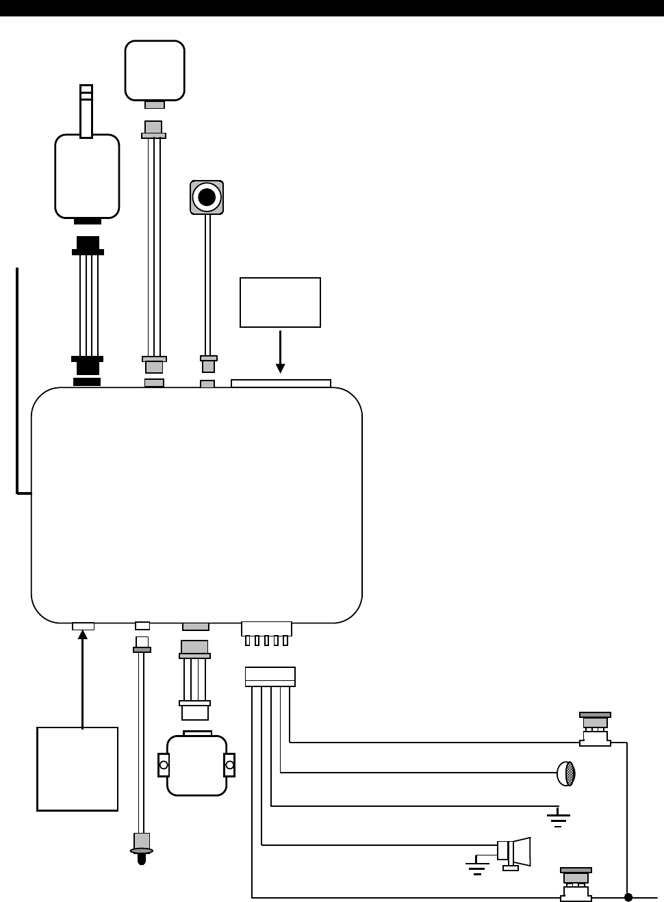
INSTALLATION DIAGRAM
H 1
6 Pin
White
H 5
4 Pin
Black
H 6
3 Pin
Brown
Transmitter
Antenna
Optional
Pager
(Knock)
Sensor
H 7
2 Pin
Blue
LED
Indicator
H 8
14 Pin White
Connector
H 8
14 Pin
White
H 2
4 Pin
Orange
Dual
Zone
Shock
Sensor
VALET
SWITCH
H 3
2 Pin
White
H 4
3 Pin
White
H 4
3 Pin White
Connector for
Door Lock &
Door unlock
Connection
1. Red / White: Parking Light Relay Power input
2. White: Parking Light Relay Output
3. Black: Ground to Vehicle Frame
4. Brown: Positive Output to Siren
5. Red: +12V Input
10A Fuse
3A Fuse
Receiver
Antenna
APR. 25, 2003
ALA761 IN 4
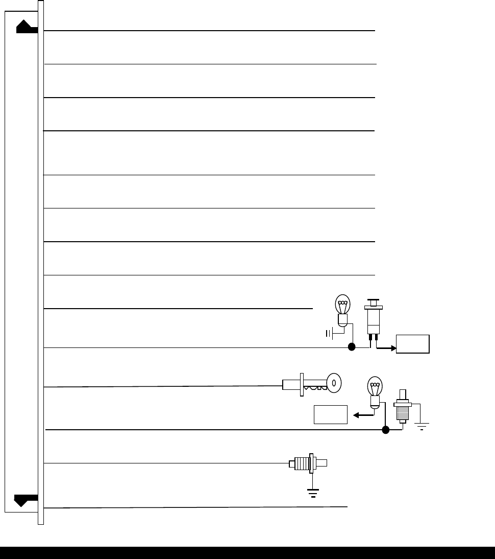
#H8. 14 PIN WHITE CONNECTOR FOR OUTPUT CONNECTION
7. Orange / White Wire: (-) 200mA Ground Output When Disarmed
8. Pink Wire: (-) 200mA 2 Steps Door Unlock Output
9. Gray Wire: (-) 200mA Channel 3 Timer Control Output
2. Blue Wire: Zone 2 Instant Trigger Ground Input
12. White/Red Wire: (-) 200mA Factory Security Disarm Output
13. Black/Violet Wire: (-) 200mA Channel 6 Timer Control Output
11. Black/Red Wire: (-) 200mA Channel 5 Timer Control Output
3. Green Wire: Zone 3 / Negative Door Pin Trigger Input:
5 . Violet Wire: Zone 3 / Positive Door Pin Trigger Input
+12V
+12V
6. Orange Wire: (-) 200mA Grounded Output When Armed
14. White Wire: (-) 200mA Dome light Output
4. Yellow Wire: Zone 5 / To Ignition Switched + 12V
10. Black/Green Wire: (-) 200mA Programmable Output
Channel 4 Timer Control Output (Factory Default Setting)
Or Horn Output
1. Black/White Wire: No Use
WIRING
Keep wiring away from moving engine parts, exhaust pipes and high-tension cable. Tape wires that pass
through holes on the firewall to prevent fraying. Watches out sharp edges that may damage wires and
causes short circuit.
CAUTION: Do not connect the wire harness to the control module until all wiring to vehicle is complete.
H1: 5 PIN WIRE HARNESS:
H1/1 Red / White wire – Parking Light Relay Power Input –
The RED/WHITE wire is the input to the flashing parking light relay. The connection of the RED/WHITE
wire will determine the output polarity of the flashing parking light relay.

APR. 25, 2003
ALA761 IN 5
If the vehicle you are working on has +12volt switched parking light, you don’t need connect this wire. This
wire already connected to +12 volt.
If the vehicle’s parking light are ground switched, cut the RED/WHITE wire, connect the RED/WHITE wire
to chassis ground.
H1/2 White wire – Parking Light Relay Output (10A power output) – (See Feature II – 4 Programming)
Connect the WHITE wire to the parking light wire coming from the headlight switch. Do not connect the
WHITE wire to the dashboard lighting dimmer switch. (Damage to the dimmer will result). The limitation of
the WHITE wire is 10 Amps max. Do not exceed this limit or damage to the alarm and parking relay will
result.
H1/3 Black wire – System Ground –
This is main ground connection of the alarm module. Make this connection to a solid section of the vehicle
frame. Do not connect this wire to any existing ground wires supplied by the factory wire loom, make the
connection to the vehicle's frame directly.
H1/4 Brown wire – Siren Drive Output – (See Feature III - 3 Programming)
This is the positive (+) output connection for the siren. Current capacity is 2 Amps. Make connection to
the (+) red wire from the siren. Make the (-) black wire coming from the siren to a good chassis ground.
H1/5 Red wire – System Power (+12V Constant) –
The RED wire supplies power to the system. Connect this wire to a constant +12 volt source.
H2. 4 PIN ORANGE CONNECTOR FOR 2 STAGE SHOCK SENSOR (ZONE 1 / 4)
1. Green Wire / Zone 1 Warn Away Input
2. Blue Wire / Zone 4 Ground Trigger
3. Black Wire / Negative
4. Red Wire / +12Volts
H3. 2 PIN WHITE CONNECTOR FOR THE LED STATUS INDICATOR:
The led indicator status should be mounted in a highly visible area such as top of the dashboard, on top of
the shifter console or on dashboard face. Leave at least 6mm space behind the mounting location for LED
housing. Once a suitable location is chosen, drill a 6mm hole. Run the LED wires through the hole then
press the 2 pin LED housing into the place. Route the LED wires to the control module.
H5. BLACK 4-PIN CONNECTOR. – TRANSMITTER ANTENNA MODUL
The transmitter antenna mounts on the location above the belt line (dashboard) of the vehicle for best
reception. We suggest you mount it on the lower left or upper left-hand side of windshield.
Warning! Do not mount in such a manner that it obstructs the driver’s view.
- Remove the protective tape backing.
- Carefully align the transmitter antenna and apply to windshield.
- Route the black connector wire behind the trim and connect to the transmitter antenna.
- Connect the other end to the control module.
- Special considerations must be made for windshield glass as some newer vehicles utilize a metallic
shielded window glass that will inhibit or restrict RF reception. In these vehicles, route the transmitter
antenna module away from metallic shielded window glass as far as possible.
H6. 3-PIN BROWN CONNECTOR FOR OPTIONAL PAGING (KNOCK) SENSOR
The optional Paging (Knock) Sensor can be add on.
1. Detach the protecting paper from the double-sided adhesive tape and attach one side of the
double-sided adhesive tape to the bottom part of the Paging (Knock) Sensor.
2. After cleansing the area around left bottom part of the front window so that it stays attached firmly, the
Paging Sensor should be attached on the front window so that the side on which a sticker with a
printed words “Tap Here Paging Driver” is attached face outward.
3. Hide the wire by carefully pushing it inside the space of the front window’s mold trim.
4. Adjust the sensitivity of the Paging Sensor, If you turn the tuning screw at the center of the Paging
Sensor clockwise, the sensitivity goes sharp and if turned counter-clockwise, the sensitivity goes dull.
H7. 2 PIN BLUE CONNECTOR FOR THE VALET SWITCH:
Select a mounting location for the switch that is easily accessible to the driver of the vehicle. The switch
does not have to be concealed, however, concealing the switch is always recommended, as this provides
an even higher level of security to the vehicle. Mount the valet switch in a hidden but accessible location.
Route the valet switch wires to the control module.
APR. 25, 2003
ALA761 IN 6
H8: 14-PIN MINI WHITE OUTPUT WIRE CONNECTOR:
H8/1. BLACK/WHITE WIRE – No Use --
H8/2 Blue wire – Ground Instant Trigger Input (Zone 2) –
This wire is the ground trigger input wire for hood/trunk pin switches.
H8/3 Green wire – Negative Door Switch Sensing Input (Zone 3) –
This wire is the ground trigger input wire for negative door pin switch. This wire is connection for
"grounding" type factory door pins locate the "common wire" that connects the door pin switches. Make
the connection of the GREEN Wire here.
H8/4. Yellow Wire – To Ignition Switched +12V –
This wire is connected to a switched 12 volts source. This wire should receive "12 volts" when the ignition
key is in the "ON" and "START" position. When the ignition is turned "OFF", this wire should receive "0"
voltage.
H8/5 Violet wire – Positive Door Switch Sensing Input (Zone 3) –
This wire is the positive trigger input wire for positive door pin switch. This wire is connection for "positive"
type factory door pins(typical FORD MOTOR). Locate the "common wire" for all door pins and make the
connection of the VIOLET Wire here.
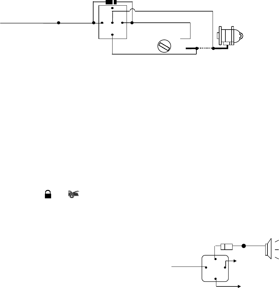
H8/6 Orange wire – (-) 200mA Grounded Output When Armed –
This wire will become grounded when the alarm is armed. The current capacity of this wire is 200mA. This
output can control starter disable, when an intrusion is detected and the system is triggered. The vehicles
prevent from any unauthorized starting.
87
87a
85
30
86
IN4003 Diode
H8/6: ORANGE wire
from control module
“Start”
“On”
White wire
X
Cut
Red wire
Orange wire
“Acc”
“Off”
Starter
Yellow wire to
Ignition Switch
H8/7. Orange / White wire – 200mA Grounded Output when Disarmed – N.O. Starter Disable –
This wire will become grounded when the alarm is disarmed. The current capacity of this wire is 200mA. It
can be connected to optional starter disable relay.
H8/8. Pink Wire – 200 mA Negative 2 Steps Unlock Oouput –
The 2 steps unlock feature will work for the most fully electronic door lock circuit. The vehicle must have
an electronic door lock switch (not the lock knob or key switch), which locks and unlocks all of vehicle's
doors. When wired for this feature, press the disarm (or unlock) button one time will disarm the alarm
and unlock the driver's door only. If press disarm (or unlock) button two times within 3 seconds, the
alarm will disarm and all doors will unlock.
H8/9 Gray wire – (-) 200mA Channel 3 Output –(See Feature IV – 1 Programming)
T his will become a 1 second pulse ground by activate channel 3 on transmitter for two seconds, the
current capacity of this wire is 200 mA. This feature allows you to remote control trunk release or other
electric device. This output can also be programmed to provide the following type of output: latched and
timer control output.
H8/10 Black / Green wire wire – (-) 200mA Programmable Output – (See Feature IV – 2 Programming)
TIMER CONTROL CHANNEL 4 OUTPUT – (Factory default setting on momentary grounded)
This wire is built-in user-programmable timer output provides a ground through this wire. Press the
transmitter and button at the same time. You may program the built-in timer to send a
ground signal for any time interval between 1 second and 2 minutes. For instance, this timer output
may be used to turn on the headlight with the remote control. Also on certain BMW, Mercedes Benz,
Jaguar and Volkswagen cars, you can use this unique timed output to allow remote closure of all
power window and sunroof without the need for an external module!
HORN OUTPUT –
This wire is provided to use the existing vehicle's
horn as the alarm system's optional's warning audible
device. It's a transistorized low current output, and
should only be connected to the low current ground
output from the vehicle's horn switch. When the
system is triggered, the horn will sound. 8586
87
87a
30
Black/Green
wire
To horn
+ 12 V
+12V Or Ground
Depending On System
Requirements
FUSE
H8/11. Black / Red wire – (-) 200mA Timer Control Channel 5 Output –
APR. 25, 2003
ALA761 IN 7
(See Feature IV – 3 Programming) (Factory default setting on momentary grounded)
This wire is built-in user-programmable timer output provides a ground through this wire. Press the
transmitter and button at the same time. You may program the built-in timer to send a ground
signal for any time interval between 1 second and 2 minutes. For instance, this timer output may be
used to turn on the headlight with the remote control. Also on certain BMW, Mercedes Benz, Jaguar
and Volkswagen cars, you can use this unique timed output to allow remote closure of all power window
and sunroof without the need for an external module!
H8/12. White / Red Wire – (-) 200mA Factory Security Disarm Signal Output –
This wire is designed to disarm a factory installed security system. This wire sends a negative (-) 1
seconds pulse upon a remote start and remote door unlocking. This makes integration of this system
into a vehicle with a factory alarm very simple. In most cases, this wire may be connected directly to the
factory alarm disarm wire. The correct wire will show nagative ground when the key is used to unlock
the doors or trunk. This wire is usually found in the kick panel area in the wiring harness coming into the
car body from the door.
H8/13. Black / Violet wire – (-) 200mA Timer Control Channel 6 Output –
(See Feature IV – 4 Programming) (Factory default setting on momentary grounded)
This wire is built-in user-programmable timer output provides a ground through this wire. Press the
transmitter and button at the same time. You may program the built-in timer to send a ground
signal for any time interval between 1 second and 2 minutes. For instance, this timer output may be
used to turn on the headlight with the remote control. Also on certain BMW, Mercedes Benz, Jaguar
and Volkswagen cars, you can use this unique timed output to allow remote closure of all power window
and sunroof without the need for an external module!
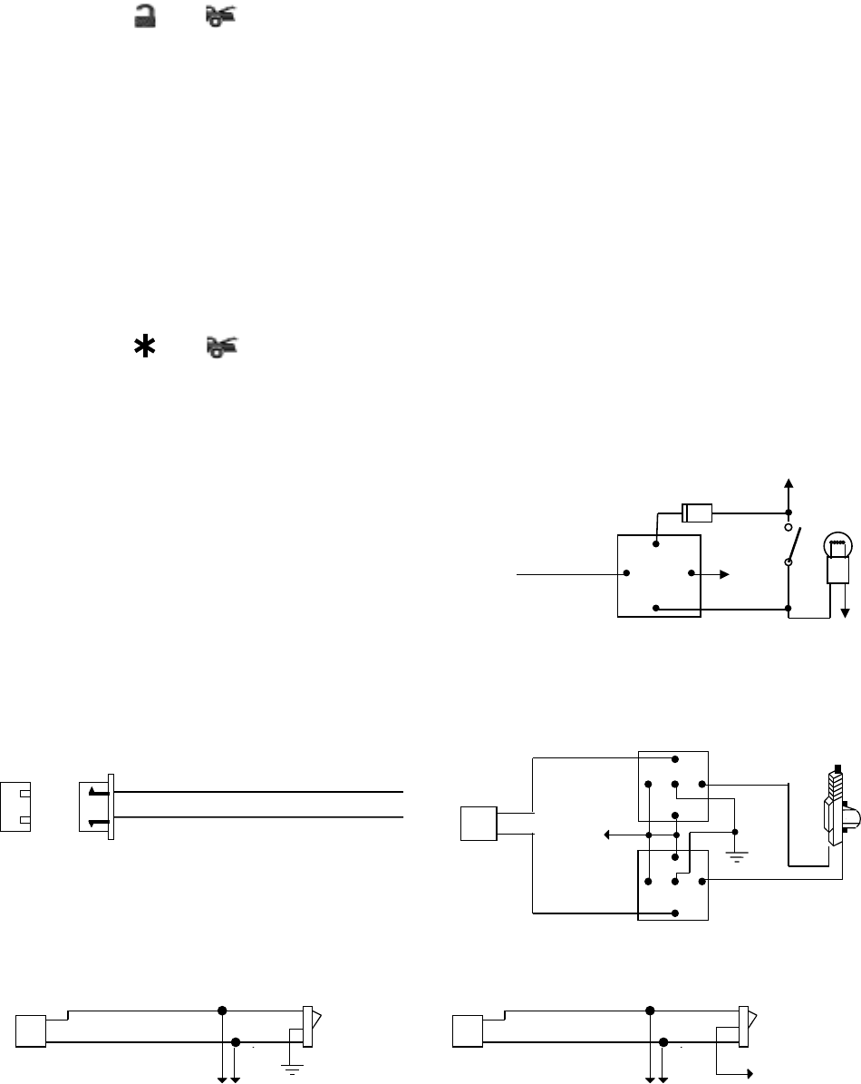
H8/14 White wire – (-) 200mA Dome Light Control Output –
This wire becomes grounded when the dome light
controls circuit active. The current capacity of this
wire is 200mA. This wire can control the operation of
the interior lights. An optional 10 Amps relay can be
used to this system for interior lights operation.
a). Upon disarming, the interior lights will remain on
for 30 seconds.
87a
86
87
30 85
Fuse
White Wire +12V
Door
Switch
Courtesy
Light
b). If the vehicle is violated, the interior light will flash for the same duration as the siren.
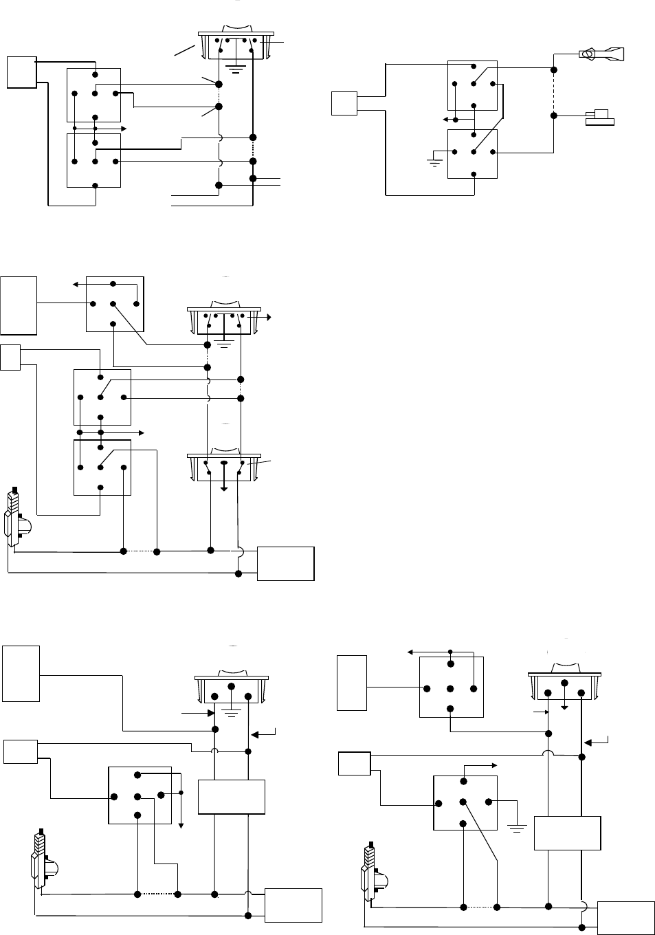
H4. 3 PIN DOOR LOCK CONNECTOR:
Blue Wire
Green Wire ( - ) Lock Pulse
( + ) Unlock Pulse
( - ) Unlock Pulse
(
+
)
Lock Pulse
I
INSTALL NEW DOOR LOCK MOTOR
Blue Wire
Green Wire
+12V
30
86
87a
85
87
30
86
87a
85
87
3 Pin
Plug To
Alarm
NEGATIVE TRIGGER DOOR LOCK SYSTE
Blue Wire Door Unlock
Green Wire Door Lock
Locking
Master
Switch
To Exiting
Door Lock Relay
POSITIVE TRIGGER DOOR LOCK SYSTEM
Blue Wire Door lock
Green Wire Door Unlock
Locking
Master
Switch
To Exiting
Door Lock Relay
+ 12V
APR. 25, 2003
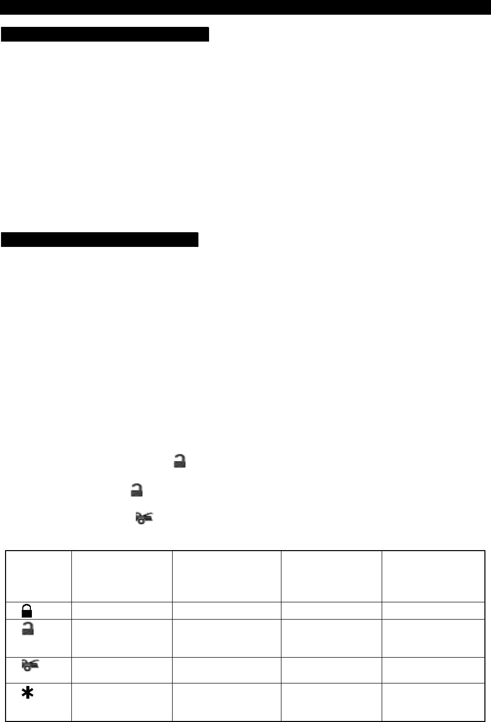
ALA761 IN 8
+12V
Master Door
Lock Switch
X
X
Splice
Splice
Cut the Existing
Lock Wire
To Door
Lock
Motor
To Slave Door
Lock switches
Cut the Existing
Unlock Wire
3 Pin Plug
To Alarm
5-WIRE ALTERNATING DOOR LOCK
30
86
87a
85
87
30
86
87a
85
87
+12V
Green Wire
Blue Wire
VACUUM OPERATED CENTROL LOCKING
Green Wire
Blue Wire
+12V
XCut
Compressor
Door Switch
30
86
87a
85
87
30
86
87a
85
87
3 Pin
Plug To
Alarm
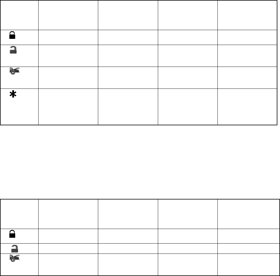
2 STEP DOOR UNLOCK WIRE CONNECTION FOR
5 WIRE ALTERNATING DOOR LOCKS
+12V
Cut the Existing
Lock Wire
Cut Existing Unlock Wire
X
Cut the Unlock Wire
Lock
Unlock
OEM Door Master Lock
OEM Slave
Door Lock
Switch
+12V LockUnlock
To All Other
Door Lock
Motors
H8/8:
14-Pin
Plug
From
Alarm
Pink Wire
x
X
Blue Wire
OEM Driver’s
Door Lock Motor
+ 12V
+ 12V
85
86 87
87A
30
30
87
85
87A
86
30
87
85
87A
86
Green Wire
H4:
3 Pin
Plug
To
Alarm
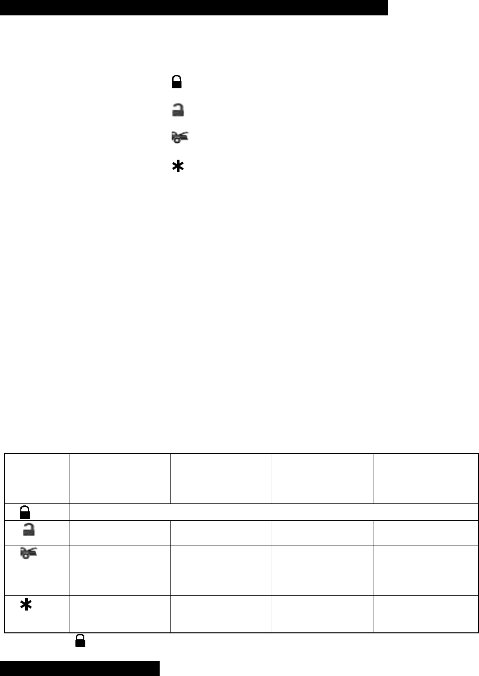
VACUUM OPERATED DOOR LOCKING SYSTEM:
TYPICAL OF MERCEDES BENZ AND AUDI.
Locate the wire under the driver's kick panel. Use the
voltmeter connecting to ground, verify that you have t
h
correct wire with the doors unlocked, the voltmeter wil
l
receive "12 volts". Lock the doors and the voltmeter w
i
read "0 volt". Move the alligator clip to +12V and the
voltmeter will receive "12 volts". Cut this wire and mak
connections. Be sure to program door lock timer to
3.5 seconds.(See Alarn Feature II – 1 Programming.)
2 STEP DOOR UNLOCK WIRE CONNECTION FOR
GROUND SWITCHED DOOR LOCKS
Cut Existing Unlock Wire
X
LockUnlock
OEM Door Master Lock Switch
To All Other
Door Lock
Motors
Pink Wire
OEM Driver's
Door Lock
Motor
Existing Neg.
Lock Wire
Existing Neg.
Unlock Wire
86
30
85
87
87A
+ 12V
Green Wire
Door Lock
Blue Wire
Door Unlock OEM Door
Lock Relay
H8/8:
14-Pin
Plug
From
Alarm
H4:
3 Pin
Plug
To
Alarm
2 STEP DOOR UNLOCK WIRE CONNECTION FOR
POSITIVE SWITCHED DOOR LOCKS
Cut Existing Unlock Wire
X
LockUnlock
OEM Door Master Lock Switch
To All Other
Door Lock
Motors
Pink Wire
OEM Driver's
Door Lock
Motor
+ 12V Existing Pos.
Lock Wire
Existing Pos.
Unlock Wire
30
87A
87
86 85
+12V
+ 12V
OEM Door
Lock Relay
86
30
85
87
87A
Green Wire
Door Unlock
Blue Wire Door Lock
H8/8:
14-Pin
Plug
From
Alarm
H4:
3 Pin
Plug
To
Alarm
APR. 25, 2003
ALA761 IN 9
ROGRAMMING
A. PROGRAMMING TRANSMITTER:
PROGRAMMING THE REMOTE TRANSMITTER
Note: This mode will only retain the last 4 remote transmitters programmed. If the transmitter memory is
exceeded, the security system will start deleting transmitters from memory in chronological order.
Enter:
1. Turn the Ignition 'switch ‘OFF/ON’ 3 TIMES and stay in ON position. Within 15 seconds.
2. Push the Valet switch 3 times and hold it until a long chirp is hearing then release the valet switch. You
are now in the Transmitter programming mode.
Program:
1. Press button on one of the transmitter until the siren responds with a confirming chirp the first transmitter
is now programmed.
2. Press button on the second transmitter until the siren responds with a confirming chirp, the second
transmitter is now programmed.
3. Apply the same procedure to program 3rd and 4th.
Exit: Turn Ignition to 'OFF' position, or leave it for 15 seconds. A 3 long chirps & 3 parking light flashes to
confirm exit.
B. FEATURES PROGRAMMING:
ALARM FEATURE “I” PRORAMMING:
1. Turn the Ignition 'switch ‘ON/OFF’ 3 TIMES and stay in OFF position.
2. Push the Valet switch 2 times and hold it until one chirp with a long chirp is hearing then release the valet
switch. You are now in the Alarm feature ‘I’ programming mode.
3. Press and release the transmitter button ‘A’ corresponding to the feature ‘A’ you want to program.
a. The siren chirps and LED pause will indicate previously setting.
b. The factory default settings is always [1] LED flash, [1] chirp.
4 Depress the transmitter button ‘A’ again to change the feature. Simple keep re-depressing the transmitter
button ‘A’ again until the module advances to your desired setting.
a. In this case, Press button ‘A’ again, the module would advance to [2] LED flash, [2] chirps.
b. Press button ‘A’ again, the module would advance to [3] LED flash, [3] chirps etc.
5. Depress the transmitter button ‘B’ corresponding to the feature ‘B’ you wants to program.
For example: To program the arming mode form “Active arming” to “Passive Arming without Passive Door
Locking”, After “Arming mode” program, the next program is “Rearm on/off” .……….
1 Turn the Ignition 'switch ‘ON/OFF’ 3 TIMES and stay in OFF position.
2 Push the Valet switch 2 times and hold it until a chirp with a long chirp is hearing then release the valet
switch.
3 Press and release the transmitter button corresponding to the feature ‘Arming mode’ you wants to
program. [1] LED flash, [1] chirp to indicate your are in features “Active Arming”.
4 Depress the transmitter button twice to change the feature. [3] LED flash, [3] chirps to indicate your
are in features “Passive Arming without Passive Door Locking ”.
5 Depress the transmitter button corresponding to the features ”Rearm on/off”’ you want to
program……..
Press
Transmitter
Button
One Chirp /
LED one pulse
Factory Default
Setting
Two Chirps /
LED two pulse
Three Chirps /
LED three pulse
Four Chirps /
LED four pulse
1 All chirps on Siren chirp on only Horn chirp on only All chirps off
2 Active arming Passive arming
without passive door
locking
Passive arming
with passive door
locking.
3 Automatic Rearm
on Automatic Rearm off
4 3 seconds Delay
Door Ajar error
chirp
30 seconds Delay
Door Ajar error chirp.
APR. 25, 2003
ALA761 IN 10
Exit: Turn Ignition to 'ON' position, or leave it for 15 seconds. A 3 long chirps & 3 parking light flashes to
confirm exit.
3 / 30 seconds Delay Door Ajar Error Chirp:
This feature controls the error chirp that is generated if the system is armed with the door trigger active. This
useful in vehicles that has a long dome light delay after the door has been closed. If the system is armed
before the dome light has turned off, the security system will generate the door trigger error chirp. Use this
feature to disable the door open error chirp.
ALARM FEATURE “II” PRORAMMING:
1 Turn the Ignition 'switch ‘ON/OFF’ 3 TIMES and stay in OFF position.
2 Push the Valet switch 4 times and hold it until two chirps with a long chirp is hearing then release the
valet
switch. You are now in the Alarm feature ‘II’ programming mode.
3 Press and release the transmitter button ‘A’ corresponding to the feature ‘A’ you want to program.
Press
Transmitter
Button
One Chirp / LED
one pulse
Factory Default
Setting
Two Chirps / LED
two pulse
Three Chirps / LED
three pulse
Four Chirps / LED
four pulse
1 0.8-second Door
lock pulses. 3.5-second Door
lock pulse. Double pulse unlock
2 Ignition controlled
door locks. Without ignition
controlled door
locks
3 Ignition controlled
door unlocks Without ignition
controlled door
unlocks
4 Pathway illumination
feature “off” Parking light turns
“on” for 30- second
upon an unlock
signal
Parking light turns
“on” for 30- second
upon an unlock
signal & 10-second
upon a lock signal.
Exit: Turn Ignition to 'ON' position, or leave it for 15 seconds. A 3 long chirps & 3 parking light flashes to
confirm exit.
ALARM FEATURE “III” PRORAMMING:
1 Turn the Ignition 'switch ‘ON/OFF’ 3 TIMES and stay in OFF position.
2 Push the Valet switch 6 times and hold it until three chirps with a long chirp is hearing then release the
valet switch. You are now in the Alarm feature ‘III’ programming mode.
3 Press and release the transmitter button ‘A’ corresponding to the feature ‘A’ you want to program.
Press
Transmitter
Button
One Chirp /
LED one pulse
Factory Default
Setting
Two Chirps /
LED two pulse
Three Chirps /
LED three pulse
Four Chirps /
LED four pulse
1 Without Car-jack
mode Active Car-jack
mode Passive Car-jack
mode
2.
3 H1/5 Brown Wire =
Constant Siren
output
H1/5 Brown Wire =
5-second pulse
Siren output
H1/5 Brown Wire =
Random pulse Siren
output
H1/5 Brown Wire =
Horn Output

APR. 25, 2003
ALA761 IN 11
4 H8/12 White/Red
Wire =
Factory Security
Disarm output
H8/12 White/Red
Wire =
Factory Security
Disarm output &
Factory Security
disarm with channel
3 on
Exit: Turn Ignition to 'ON' position, or leave it for 15 seconds. A 3 long chirps & 3 parking light flashes to
confirm exit.
Factory Security Disarm Output: It will output a 200mA (-) pulse whenever the system is disarmed. This
makes integration of this system into a vehicle with a factory alarm very simple.
Factory Security Disarm output & Factory Security disarm with channel 3 on: It will output a 200mA (-)
pulse whenever the system is disarmed or channel 3 is activated. This makes integration of this system into
a vehicle with a factory alarm very simple.
ALARM FEATURE “IV” PRORAMMING:
1. Turn the Ignition 'switch ‘ON/OFF’ 3 TIMES and stay in OFF position.
2. Push the Valet switch 8 times and hold it until four chirps with a long chirp is hearing then release the
valet switch. You are now in the Alarm feature ‘IV’ programming mode.
3. Press and release the transmitter button ‘A’ corresponding to the feature ‘A’ you want to program.
Press
Transmitter
Button
One Chirp /
LED one pulse
Factory Default
Setting
Two Chirps /
LED two pulse
Three Chirps /
LED three pulse
Four Chirps /
LED four pulse
1 H8/9 Gray Wire
Channel 3 Output =
1 second pulse
output for trunk
release.
H8/9 Gray Wire
Channel 3 Output =
Latched output
H8/9 Gray Wire
Channel 3 Output =
Latched output and
reset with ignition
“on”
H8/9 Gray Wire
Channel 3 Output =
Timer programming
(set to any interval
between 1 second
and 2 minutes.)
2. H8/10 Black / Green
Wire Channel 4
Output =
Momentary output
H8/10 Black / Green
Wire Channel 4
Output =
Latched output
H8/10 Black / Green
Wire = Horn Output H8/10 Black / Green
Wire Channel 4
Output =
Timer programming
(set to any interval
between 1 second
and 2 minutes.)
3 H8/11 Black / Red
Wire Channel 5
Output =
Momentary output
H8/11 Black / Red
Wire Channel 5
Output =
Latched output
H8/11 Black / Red
Wire Channel 5
Output =
Latched output and
reset with ignition
“on”
H8/11 Black / Red
Wire Channel 5
Output =
Timer programming
(set to any interval
between 1 second
and 2 minutes.)
4 H8/13 Black / Violet
Wire Channel 6
Output =
Momentary output
H8/13 Black / Violet
Wire Channel 6
Output =
Latched output
H8/13 Black / Violet
Wire Channel 6
Output =
Latched output and
reset with ignition
“on”
H8/13 Black / Violet
Wire Channel 6
Output =
Timer programming
(set to any interval
between 1 second
and 2 minutes.)
Exit: Turn Ignition to 'ON' position, or leave it for 15 seconds. A 3 long chirps & 3 parking light flashes to
confirm exit.
APR. 25, 2003
ALA761 IN 12
Channel 3 (4/ 5 / 6) Timer Control Output Programming
Enter:
1. Turn the Ignition 'switch ‘ON/OFF’ 3 TIMES and stay in OFF position.
2. Push the Valet switch 8 times and hold it until four chirps with a long chirp is hearing then release the
valet switch. You are now in the Alarm feature ‘IV’ programming mode.
Timer Program:
1-a. Press and release the transmitter button 4 times, [4] LED flash, [4] siren/horn chirp to indicate
your are in features “Channel 3 Timer Programming mode”.
1-b. Press and release the transmitter button 4 times, [4] LED flash, [4] siren/horn chirp to indicate
your are in features “Channel 4 Timer Programming mode”.
1-c. Press and release the transmitter button 4 times, [4] LED flash, [4] siren/horn chirp to indicate
your are in features “Channel 5 Timer Programming mode”.
1-d. Press and release the transmitter button 4 times, [4] LED flash, [4] siren/horn chirp to indicate
your are in features “Channel 6 Timer Programming mode”.
2. Press and hold the valet switch, the timer will immediately start.
3. When the desired interval has passed, release the valet switch. 1 long chirp for confirmation.
(Set to any interval between 1 second and 2 minutes)
Note 1:
If your built-in timer controls window/sunroof closure in your car DO NOT change the timer setting! This
requires installer-only programming. Changing the value will adversely effect operation and may cause
damage.
Note 2:
Momentary output = The momentary output selection will output a negative signal from the Channel 3
(4/5/6) output immediately when the channel 3 (4/5/6) button is pressed and will continue until the button is
release.
Latched output = The latched output selection will output a negative signal as soon as the Channel 3 (4/5/6)
button is pressed and will continue until the button is pressed again.
Latched output / reset with ignition = The latched / reset with ignition output selection operates just like
the latched output but will reset or stop when the ignition is turned on.
ALARM FEATURE “V” PRORAMMING:
1. Turn the Ignition 'switch ‘ON/OFF’ 3 TIMES and stay in OFF position.
2. Push the Valet switch 10 times and hold it until five chirps with a long chirp is hearing then release the
valet
switch. You are now in the Alarm feature ‘V’ programming mode.
3. Press and release the transmitter button ‘A’ corresponding to the feature ‘A’ you want to program.
Press
Transmitter
Button
One Chirp /
LED one pulse
Factory Default
Setting
Two Chirps /
LED two pulse
Three Chirps /
LED three pulse
Four Chirps /
LED four pulse
1 Exit the programming mode. (3 long chirp & 3 parking light flashes to confirm this exit.)
2. Override Without
Password Pin Code Override With
Password Pin Code
3 “TEST” Mode for
Zone 2 / instant
trigger & Zone 3 /
Door trigger
“TEST” Mode for
Zone 1 & Zone 4 (2
Stage Shock
Sensor)
4 Panic with Ignition
off Panic with Ignition
on & off Panic with Ignition
on & off. Panic
with No time limit.
Without Panic
function.
Exit: Press the button on the transmitter. A 3 long chirps & 3 parking light flashes to confirm exit.
Password Pin Code Setup:
Enter:
1. Turn the Ignition 'switch ‘ON/OFF’ 3 times and stay in OFF position.

APR. 25, 2003
ALA761 IN 13
2. Push the Valet switch 10 times and hold it until five chirps with a long chirp is hearing then release the
valet switch. You are now in the Alarm feature ‘V’ programming mode. You can program or delete the
password pin code as below:
Program:
1. Press and release the transmitter button twice, [2] LED flash, [2] siren/horn chirp to indicate your are
in features “Password Pin Code Programming mode”.
2. Within 5 seconds, begin to enter your chosen first 9ths digit by pressing and releasing the valet Switch
from 1 – 9 times.
3. Within 15 seconds of the last entered 9ths digit, turn the Ignition switch to “ON” position.
4. Within 15 seconds, enter your chosen second 9ths digit by pressing and releasing the valet Switch from
1 – 9 times.
5. Finish by turning the ignition switch to “OFF” position.
If the new password code was accepted, the unit would report back the newly entered code, by flashing the
LED, first indicating the first digit code has been memorized, pause and then the second digit code. The unit
will report the new code three times with a one-second’s pause between each code.
Note: If 15 seconds of inactivity expire, or if the ignition switch is turned “ON” for more then 5 seconds during
of above steps, the unit will revert back to the last successfully stored code. A [3] long chirps to confirm exit.
Will revert back to the last successfully stored code
Delete Password Pin Code / Override Without Password Pin Code (Factory default setting):
Within 15 seconds, press and hold the transmitter button for 4 seconds. A one long chirps to confirm
Deleted the Password Pin Code.
Example: To program the Password Code 92, you would;
Enter:
1. Turn the Ignition 'switch ‘ON/OFF’ 3 times and stay in OFF position.
2. Push the Valet switch 10 times and hold it until five chirps with a long chirp is hearing then release the
valet switch. You are now in the Alarm feature ‘V’ programming mode.
Program:
1. Press and release the transmitter button twice, [2] LED flash, [2] siren/horn chirp to indicate your are
in features “Password pin code programming mode”.
2. Within 5 seconds, press and release the valet Switch 9 times.
3. Within 15 seconds of the last entered 9ths digit, Turn the Ignition Switch to “ON” position.
4. Within 15 seconds press the valet Switch twice.
5. Turn the Ignition Switch to “OFF’ position.
You will note the LED flashing nine times, pause and then flash two times, pause. This pattern will be
repeated three times indicating the new code (92) has been accepted and stored in memory.
Exit: Press any button (except button) of the transmitter to exit the password pin set up mode.
TEST MODE
In this test mode, this system can test the Zone 2 (Instant ground trigger), the Zone 3 (Door trigger), and the
Zone 1 & Zone 4 (2 stage shock sensor) sensitivity. The installer can save time to test the 2 stage shock
sensor sensitivity and sensor without using the traditional arming/disarming procedures to test the sensors.
Enter:
1. Turn the Ignition 'switch ‘ON/OFF’ 3 TIMES and stay in OFF position.
2. Push the Valet switch 10 times and hold it until five chirps with a long chirp is hearing then release the
valet switch. You are now in the Alarm feature ‘V’ programming mode.
a. Test the Zone 2 / Instant Ground Trigger & Zone 3 / Door Trigger:
Press and release the transmitter button once. [1] LED flash, [1] siren/horn chirp to indicate your
are in Zone 2 / instant ground trigger and Zone 3 / Door trigger test mode.
Trigger sensor Siren chirps
Zone 2 / Instant Ground trigger (H8/2 Blue wire) 2
Zone 3 / Door trigger (H8/3 Green or H8/5 Violet wire) 3
b. Test the Zone 1 & Zone 4 / Two Stage Shock Sensor (Connected to H2 4 Pin Plug):
Press and release the transmitter button twice. [2] LED flash, [2] siren/horn chirps to indicate your
are in the shock sensor (connected to H2 4 pin plug) test mode.
1. Activate the warn-away (first stage of the shock sensor / Zone 1), system will emit a short chirp.
2. Activate the full alarm (second stage of the shock sensor / Zone 4), system will emit a long chirp.
3. Continue to test the shock sensor until reach the proper sensitivity.

APR. 25, 2003
ALA761 IN 14
RETURN TO FACTORY DEFAULT SETTING
1. Turn the ignition ON then OFF 3 TIMES and stay in OFF position.
2. Push the Valet switch 12 times and hold it until six chirp with a long chirp is hearing then release the valet
switch. You are now in the “Return To Factory Default Setting” programming mode.
3. Press and hold the and button at the same time on the transmitter for 6 seconds, there will be a
confirmation six chirp with 3 long chirp & 3 parking light flashes to confirm the system “Alarm Feature
Programming “ all returns to factory default setting then exit.
Exit: Turn Ignition to 'ON' position, or leave it for 15 seconds. A 3 long chirps & 3 parking light flashes to
confirm exit.
This device complies with part 15 of the FCC rules. Operation is subject to the following two conditions:
(1) This device may not cause harmful interference.
(2) This device must accept any interference received: including interference that may cause undesired
operation.
Note: The manufacturer is not responsible for any radio of TV interference caused by unauthorized
modification to this equipment. Such modification could void the user’ authority to operate the equipment.