Advance Security TR45 Car Alarm Transceiver User Manual one sheet E4 instl manual
Advance Security Inc Car Alarm Transceiver one sheet E4 instl manual
UserManual.wiki
>
Advance Security
>
TR45 User Manual
User manual
Navigation menu
Upload a User Manual
Namespaces
Wiki Guide
HTML
PDF
Info
Views
User Manual
Discussion / Help
Navigation
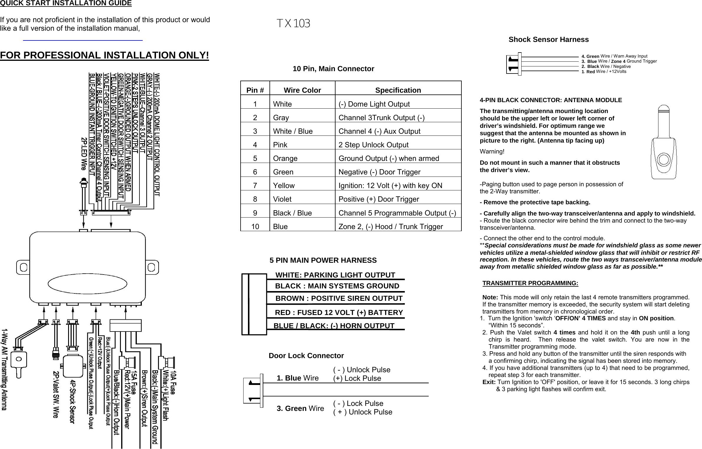
![2 STEP DOOR UNLOCK WIRE CONNECTION FOR 5 WIRE ALTERNATING DOOR LOCKS +12VCut the ExistingLock WireCut Existing Unlock XCut the Unlock WireLockUnlockOEM Door Master Lock OEM SlaveDoor LockSwitch+12VLockUnlockTo All OtherDoor LockMotorsH2/13: 22-Pin Plug From Alarm White/Green Wire x XBlue Wire OEM Driver’s Door Lock Motor+ 12V 8586 8787a303087 8587a863087 8587a86Green Wire H9: 3 Pin Plug To Alarm Red +12V 2 STEP DOOR UNLOCK WIRE CONNECTION FOR 5 WIRE ALTERNATING DOOR LOCKS +12VCut the ExistingLock WireCut Existing Unlock XCut the Unlock WireLockUnlockOEM Door Master Lock OEM SlaveDoor LockSwitch+12VLockUnlockTo All OtherDoor LockMotorsH2/13: 22-Pin Plug From Alarm White/GreenWire x XBlue Wire OEM Driver’s Door Lock Motor+ 12V8586 8787a3030878587a8630878587a86Green WireH9: 3 Pin Plug To AlarmRed +12V FEATURE “B” PROGRAMMING: Turn the Ignition switch ‘ON/OFF’ 3 TIMES and stay in OFF position. Push the Valet switch 4 times (holding in on the 4th push) until one long chirp is heard then release the valet switch. You are now in the Alarm feature “B” programming mode. Press and release the transmitter button corresponding to the feature you want to program. FEATURE “C” PROGRAMMING: 1 Turn the Ignition 'switch ‘ON/OFF’ 3 TIMES and stay in OFF position. 2 Push the Valet switch 5 times (holding in on the 5th push) until one long chirp is heard then release the valet switch. You are now in the Alarm feature “C” programming mode. 3 Press and release the transmitter button corresponding to the feature you want to program. FEATURE “A” PROGRAMMING: 1. Turn the Ignition 'switch ‘ON/OFF’ 3 TIMES and stay in OFF position. 2. Push the Valet switch 3 times (holding in on the 3rd push) until one long chirp is heard. Then release the valet switch. You are now in the Alarm feature “A” programming mode. 3. Press and release the transmitter button corresponding to the feature you want to program. a. The siren chirps and LED pause will indicate previously setting. b. The factory default settings is always [1] LED flash, [1] chirp. 4 Depress the transmitter button to change the feature. Simply keep re-depressing the transmitter button until the system advances to your desired setting. Press the transmitter button corresponding to the feature you want to program. Press Transmitter Button One Chirp / LED one pulse Factory Default Setting Two Chirps / LED two pulses Three Chirps / LED three pulses Four Chirps / LED four pulses 1 All Confirmation chirps on Siren Confirmation chirp on only Horn Confirmation chirp on only All Confirmation chirps off 2 Automatic Rearm off Automatic Rearm on 3 Instant Door Ajar error chirp 45 seconds delay Door Ajar error chirp. 4 + Without Car-jack mode Active Car-jack mode Passive Car-jack mode Exit: Turn Ignition to 'ON' position, or leave it for 15 seconds. 3 long chirps & 3 parking light flashes will confirm exit. Channel 2/3/4 Timer Control Output Programming: Enter: 1. Turn the Ignition 'switch ‘ON/OFF’ 5 TIMES and stay in OFF position. 2. Push the Valet switch 5 times and hold in on the 5th push, when a long chirp is heard, then release the valet switch. You are now in the Alarm feature ‘C’ programming mode. Timer Program Channel 2/3/4: 1-a. CH 3 Press and release the transmitter button 3 times, [3] LED flash, [3] siren/horn chirp to indicate you are in features “Channel 3 Timer Programming mode”. 1-b. CH 4 Press and release the transmitter button 3 times, [3] LED flash, [3] siren/horn chirp to indicate you are in features “Channel 4 Timer Programming mode”. 1-c. CH 5 Press and release the transmitter button 4 times, [4] LED flash, [4] siren/horn chirp to indicate you are in features “Channel 5 Timer Programming mode”. 2. Press and hold the valet switch, the timer will immediately start. 3. When the desired interval has passed, release the valet switch. 1 long chirp for confirmation. (Set to any interval between 1 second and 2 minutes) Note 1: If your built-in timer controls window/sunroof closure in your car DO NOT change the timer setting! This requires installer-only programming. Changing the value will adversely affect operation and may cause damage. Note 2: Latched output = The latched output selection will send a negative signal as soon as the Channel 4 button is pressed and will continue until the button is pressed again. Press Transmitter Button One Chirp / LED one pulse Factory Default Setting Two Chirps / LED two pulses Three Chirps / LED three pulses Four Chirps / LED four pulses 1 0.8-second Door lock pulses. 3.5-second Door lock pulse. Double pulse unlock Door lock with “Comfort Feature” 2 Active arming Passive arming without passive door locking Passive arming with passive door locking. 3 Ignition controlled door locks & unlocks Ignition controlled door locks only Ignition controlled door unlocks only Without ignition controlled door locks & unlocks 4. + Horn chirp Duration Standard Horn chirp Duration 50 mS Horn chirp Duration 30 mS Horn chirp duration 10 mS 5 Pathway illumination feature “off” Parking light turns “on” for 30- second upon an unlock signal Parking light turns “on” for 30- second upon an unlock signal & 10-second upon a lock signal. Press Transmitter Button One Chirp / LED one pulse Factory Default Setting Two Chirps / LED two pulses Three Chirps / LED three pulses Four Chirps / LED four pulses 1 Channel 3 Output = 2 sec. Pulse Channel 3 Output = Latched Channel 3 Output = Timer control Pager Output 2 Channel 5 Output = 2 sec. Pulse Channel 5 Output = Latched Channel 5 Output = Timer control Pager Output 3 Pink Wire = 2 Step Unlock Pink Wire = Factory Disarm Channel 4 Output = 2 sec. Pulse Channel 4 Output = Latched Channel 4 Output = Timer control Pager Output Exit: Turn Ignition to 'OFF' position, or leave it for 15 seconds. 3 long chirps and 3 Parking Light will confirm exit. This Alarm and Keyless Entry System has been designed to be installed BY PROFESSIONAL INSTALLERS ONLY.. Do not install any component near the brake, gas pedal or steering linkage. Some vehicles have a factory installed transponder immobilizer system that can severely complicate the installation. There is a possibility that this system cannot be installed on some immobilizer-equipped vehicles. Most vehicles have an SRS air bag system. Use extreme care and do not probe any wires of the SRS system. Disconnect the car battery before beginning work on the vehicle. Check behind panels before drilling any holes. Ensure that no wiring harness or other components are located behind the panels that would otherwise be damaged. Do not use conventional crimp lock, bullet on any wiring. Poor wiring, i.e. taped joints will possibly introduce unreliability into the alarm system and may result in false alarms or incorrect operation. We suggest soldering all connection points. Install the wiring neatly under carpets or behind trim to prevent possible damage to wires.](https://usermanual.wiki/Advance-Security/TR45/User-Guide-1481791-Page-2.png)