Advance Security TR45 Car Alarm Transceiver User Manual one sheet E4 instl manual
Advance Security Inc Car Alarm Transceiver one sheet E4 instl manual
User manual
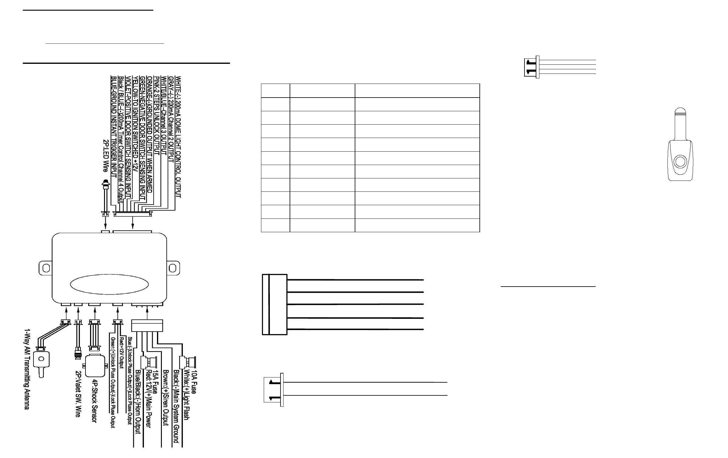
Pin # Wire Color Specification
1 White (-) Dome Light Output
2 Gray Channel 3Trunk Output (-)
3 White / Blue Channel 4 (-) Aux Output
4 Pink 2 Step Unlock Output
5 Orange Ground Output (-) when armed
6 Green Negative (-) Door Trigger
7 Yellow Ignition: 12 Volt (+) with key ON
8 Violet Positive (+) Door Trigger
9 Black / Blue Channel 5 Programmable Output (-)
10 Blue Zone 2, (-) Hood / Trunk Trigger
1. Blue Wire
3. Green Wire ( - ) Lock Pulse
( + ) Unlock Pulse
( - ) Unlock Pulse
(
+
)
Lock Pulse
4. Green Wire / Warn Away Input
3. Blue Wire / Zone 4 Ground Trigger
2. Black Wire / Negative
1. Red Wire / +12Volts
22 - Pin Connector
5 PIN MAIN POWER HARNESS
Door Lock Connector
QUICK START INSTALLATION GUIDE
If you are not proficient in the installation of this product or would
like a full version of the installation manual,
FOR PROFESSIONAL INSTALLATION ONLY!
WHITE: PARKING LIGHT OUTPUT
BLACK : MAIN SYSTEMS GROUND
BROWN : POSITIVE SIREN OUTPUT
RED : FUSED 12 VOLT (+) BATTERY
BLUE / BLACK: (-) HORN OUTPUT
TRANSMITTER PROGRAMMING:
Note: This mode will only retain the last 4 remote transmitters programmed.
If the transmitter memory is exceeded, the security system will start deleting
transmitters from memory in chronological order.
1. Turn the Ignition 'switch ‘OFF/ON’ 4 TIMES and stay in ON position.
“Within 15 seconds”.
2. Push the Valet switch 4 times and hold it on the 4th push until a long
chirp is heard. Then release the valet switch. You are now in the
Transmitter programming mode.
3. Press and hold any button of the transmitter until the siren responds with
a confirming chirp, indicating the signal has been stored into memory.
4. If you have additional transmitters (up to 4) that need to be programmed,
repeat step 3 for each transmitter.
Exit: Turn Ignition to 'OFF' position, or leave it for 15 seconds. 3 long chirps
& 3 parking light flashes will confirm exit.
10 Pin, Main Connector
Shock Sensor Harness
4-PIN BLACK CONNECTOR: ANTENNA MODULE
The transmitting/antenna mounting location
should be the upper left or lower left corner of
driver’s windshield. For optimum range we
suggest that the antenna be mounted as shown in
picture to the right. (Antenna tip facing up)
Warning!
Do not mount in such a manner that it obstructs
the driver’s view.
-Paging button used to page person in possession of
the 2-Way transmitter.
- Remove the protective tape backing.
- Carefully align the two-way transceiver/antenna and apply to windshield.
- Route the black connector wire behind the trim and connect to the two-way
transceiver/antenna.
- Connect the other end to the control module.
**Special considerations must be made for windshield glass as some newer
vehicles utilize a metal-shielded window glass that will inhibit or restrict RF
reception. In these vehicles, route the two ways transceiver/antenna module
away from metallic shielded window glass as far as possible.**
TX103

2 STEP DOOR UNLOCK WIRE CONNECTION FOR
5 WIRE ALTERNATING DOOR LOCKS
+12V
Cut the Existing
Lock Wire
Cut Existing Unlock
X
Cut the Unlock Wire
Lock
Unlock
OEM Door Master Lock
OEM Slave
Door Lock
Switch
+12V
LockUnlock
To All Other
Door Lock
Motors
H2/13:
22-Pin
Plug
From
Alarm
White/Green
Wire
x
X
Blue Wire
OEM Driver’s
Door Lock Motor
+ 12V
85
86 87
87a
30
30
87
85
87a
86
30
87
85
87a
86
Green Wire
H9:
3 Pin
Plug
To
Alarm
Red +12V
FEATURE “B” PROGRAMMING:
Turn the Ignition switch ‘ON/OFF’ 3 TIMES and stay in OFF position.
Push the Valet switch 4 times (holding in on the 4th push) until one long
chirp is heard then release the valet switch. You are now in the Alarm
feature “B” programming mode.
Press and release the transmitter button corresponding to the feature you
want to program.
FEATURE “C” PROGRAMMING:
1 Turn the Ignition 'switch ‘ON/OFF’ 3 TIMES and stay in OFF position.
2 Push the Valet switch 5 times (holding in on the 5th push) until one long chirp is heard
then release the valet switch. You are now in the Alarm feature “C” programming
mode.
3 Press and release the transmitter button corresponding to the feature you want to
program.
FEATURE “A” PROGRAMMING:
1. Turn the Ignition 'switch ‘ON/OFF’ 3 TIMES and stay in OFF position.
2. Push the Valet switch 3 times (holding in on the 3rd push) until one
long chirp is heard. Then release the valet switch. You are now in the
Alarm feature “A” programming mode.
3. Press and release the transmitter button corresponding to the feature
you want to program.
a. The siren chirps and LED pause will indicate previously setting.
b. The factory default settings is always [1] LED flash, [1] chirp.
4 Depress the transmitter button to change the feature. Simply keep re-
depressing the transmitter button until the system advances to your
desired setting.
Press the transmitter button corresponding to the feature you want to
program.
Press
Transmitt
er
Button
One Chirp /
LED one pulse
Factory Default
Setting
Two Chirps
/
LED two
pulses
Three
Chirps /
LED three
pulses
Four Chirps
/
LED four
pulses
1 All Confirmation
chirps on
Siren
Confirmatio
n chirp on
only
Horn
Confirmation
chirp on only
All
Confirmation
chirps off
2 Automatic
Rearm off Automatic
Rearm on
3 Instant Door
Ajar error chirp
45 seconds
delay Door
Ajar error
chirp.
4 + Without Car-
jack mode
Active Car-
jack mode
Passive
Car-jack
mode
Exit: Turn Ignition to 'ON' position, or leave it for 15 seconds. 3 long chirps &
3 parking light flashes will confirm exit.
Channel 2/3/4 Timer Control Output Programming:
Enter:
1. Turn the Ignition 'switch ‘ON/OFF’ 5 TIMES and stay in OFF position.
2. Push the Valet switch 5 times and hold in on the 5th push, when a
long chirp is heard, then release the valet switch. You are now in the
Alarm feature ‘C’ programming mode.
Timer Program Channel 2/3/4:
1-a. CH 3 Press and release the transmitter button 3 times, [3] LED
flash, [3] siren/horn chirp to indicate you are in features “Channel 3
Timer Programming mode”.
1-b. CH 4 Press and release the transmitter button 3 times, [3] LED
flash, [3] siren/horn chirp to indicate you are in features “Channel 4
Timer Programming mode”.
1-c. CH 5 Press and release the transmitter button 4 times, [4] LED
flash, [4] siren/horn chirp to indicate you are in features “Channel 5
Timer Programming mode”.
2. Press and hold the valet switch, the timer will immediately start.
3. When the desired interval has passed, release the valet switch. 1
long chirp for confirmation.
(Set to any interval between 1 second and 2 minutes)
Note 1:
If your built-in timer controls window/sunroof closure in your car DO
NOT change the timer setting! This requires installer-only
programming. Changing the value will adversely affect operation
and may cause damage.
Note 2:
Latched output = The latched output selection will send a negative
signal as soon as the Channel 4 button is pressed and will continue
until the button is pressed again.
Press
Transmitter
Button
One Chirp / LED one
pulse
Factory Default
Setting
Two Chirps / LED
two pulses
Three Chirps /
LED three
pulses
Four Chirps
/ LED four
pulses
1 0.8-second Door
lock pulses. 3.5-second Door
lock pulse.
Double pulse
unlock
Door lock
with
“Comfort
Feature”
2
Active arming
Passive arming
without passive
door locking
Passive arming
with passive
door locking.
3 Ignition controlled
door locks &
unlocks
Ignition controlled
door locks only
Ignition
controlled door
unlocks only
Without
ignition
controlled
door locks &
unlocks
4. + Horn chirp Duration
Standard
Horn chirp
Duration
50 mS
Horn chirp
Duration
30 mS
Horn chirp
duration
10 mS
5 Pathway
illumination feature
“off”
Parking light
turns “on” for 30-
second upon an
unlock signal
Parking light
turns “on” for
30- second
upon an unlock
signal & 10-
second upon a
lock signal.
Press
Transmitte
r
Button
One Chirp / LED one
pulse
Factory Default
Setting
Two Chirps / LED
two pulses
Three Chirps /
LED three
pulses
Four Chirps
/ LED four
pulses
1 Channel 3 Output =
2 sec. Pulse
Channel 3 Output
=
Latched
Channel 3
Output =
Timer control
Pager
Output
2 Channel 5
Output =
2 sec. Pulse
Channel 5 Output
=
Latched
Channel 5
Output =
Timer control
Pager
Output
3 Pink Wire =
2 Step Unlock
Pink Wire =
Factory Disarm
Channel 4 Output =
2 sec. Pulse
Channel 4
Output =
Latched
Channel 4
Output =
Timer control
Pager
Output
Exit: Turn Ignition to 'OFF' position, or leave it for 15 seconds. 3 long chirps and 3 Parking
Light will confirm exit.
This Alarm and Keyless Entry System has been designed to be installed
BY PROFESSIONAL INSTALLERS ONLY..
Do not install any component near the brake, gas pedal or steering
linkage.
Some vehicles have a factory installed transponder immobilizer system
that can severely complicate the installation. There is a possibility that this
system cannot be installed on some immobilizer-equipped vehicles.
Most vehicles have an SRS air bag system. Use extreme care and do not
probe any wires of the SRS system.
Disconnect the car battery before beginning work on the vehicle.
Check behind panels before drilling any holes. Ensure that no wiring
harness or other components are located behind the panels that would
otherwise be damaged.
Do not use conventional crimp lock, bullet on any wiring. Poor wiring, i.e.
taped joints will possibly introduce unreliability into the alarm system and
may result in false alarms or incorrect operation. We suggest soldering all
connection points.
Install the wiring neatly under carpets or behind trim to prevent possible
damage to wires.

FCC COMPLIANCE
This device complies with Part 15 of the FCC rules and with RSS-210 of
Industry Canada. Operation is subject to the following two conditions:
1. This device may not cause harmful interference, and
2. This device must accept any interference received, including any interference
that may cause undesired operation.
Warning!
Changes or modifications not expressly approved by the party responsible for
compliance could void the user’s authority to operate the equipment.