Advanced RF Technologies ADRFTECH003 Epoch- M1P Repeater User Manual 1
Advanced RF Technologies, Inc. Epoch- M1P Repeater 1
UserManual.wiki
>
Advanced RF Technologies
>
ADRFTECH003 User Manual
>
Users Manual
Contents
1.
Users Manual
2.
QickStart Guide
3.
Software Setup Guide
4.
USB Driver Setup Guide
Users Manual
Navigation menu
Upload a User Manual
Namespaces
Wiki Guide
HTML
PDF
Info
Views
User Manual
Discussion / Help
Navigation

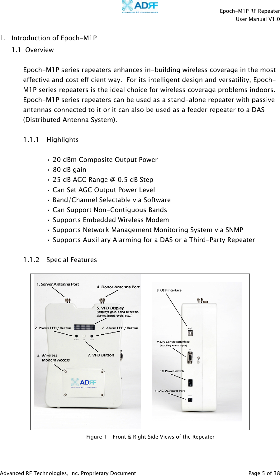
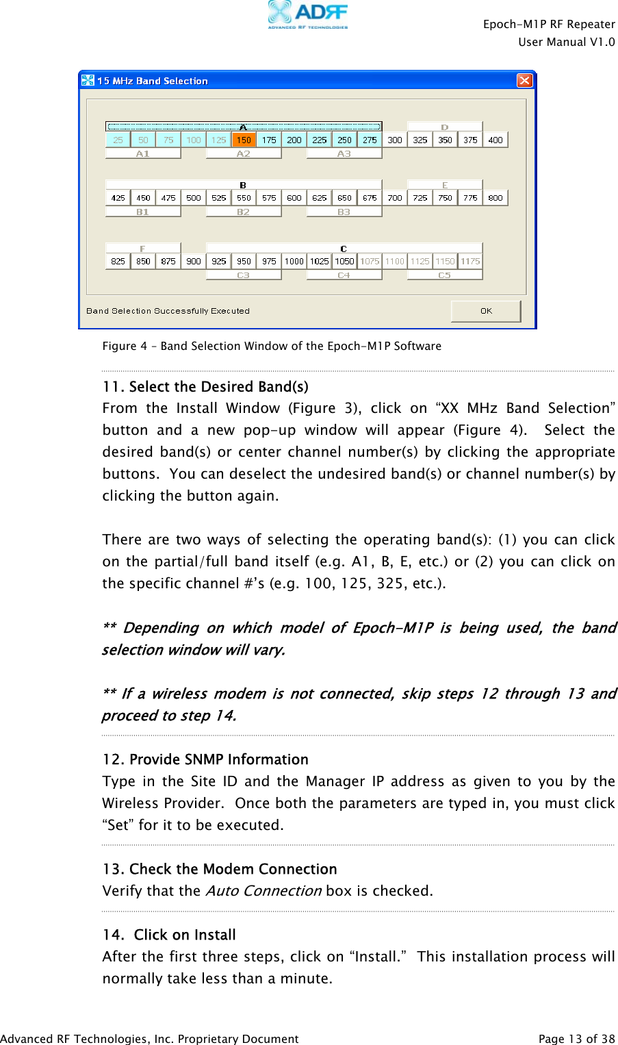
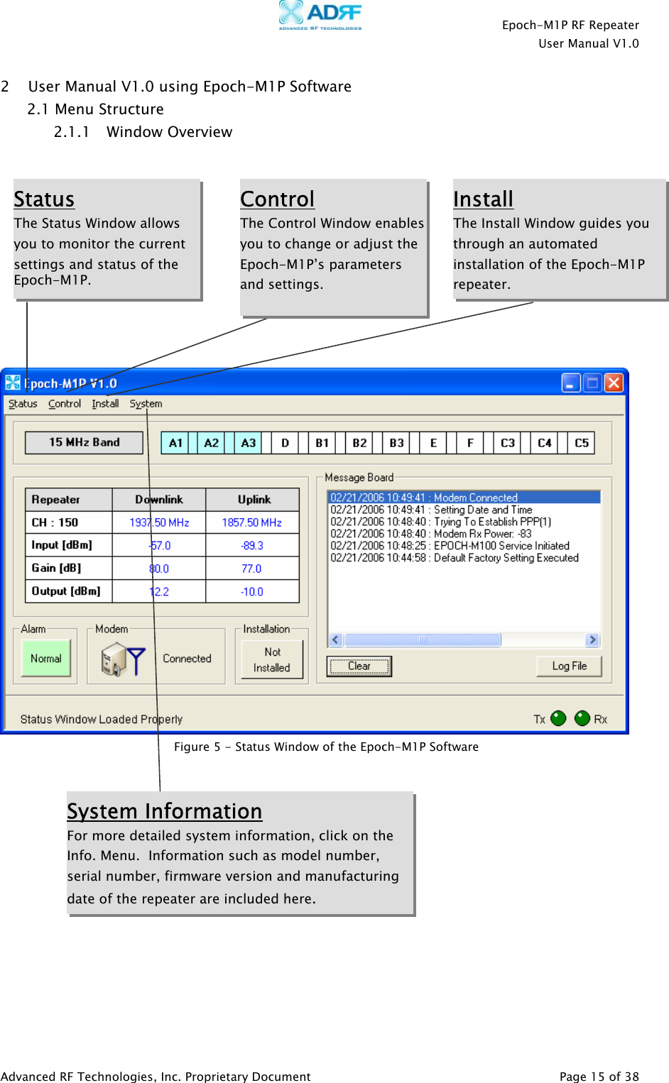
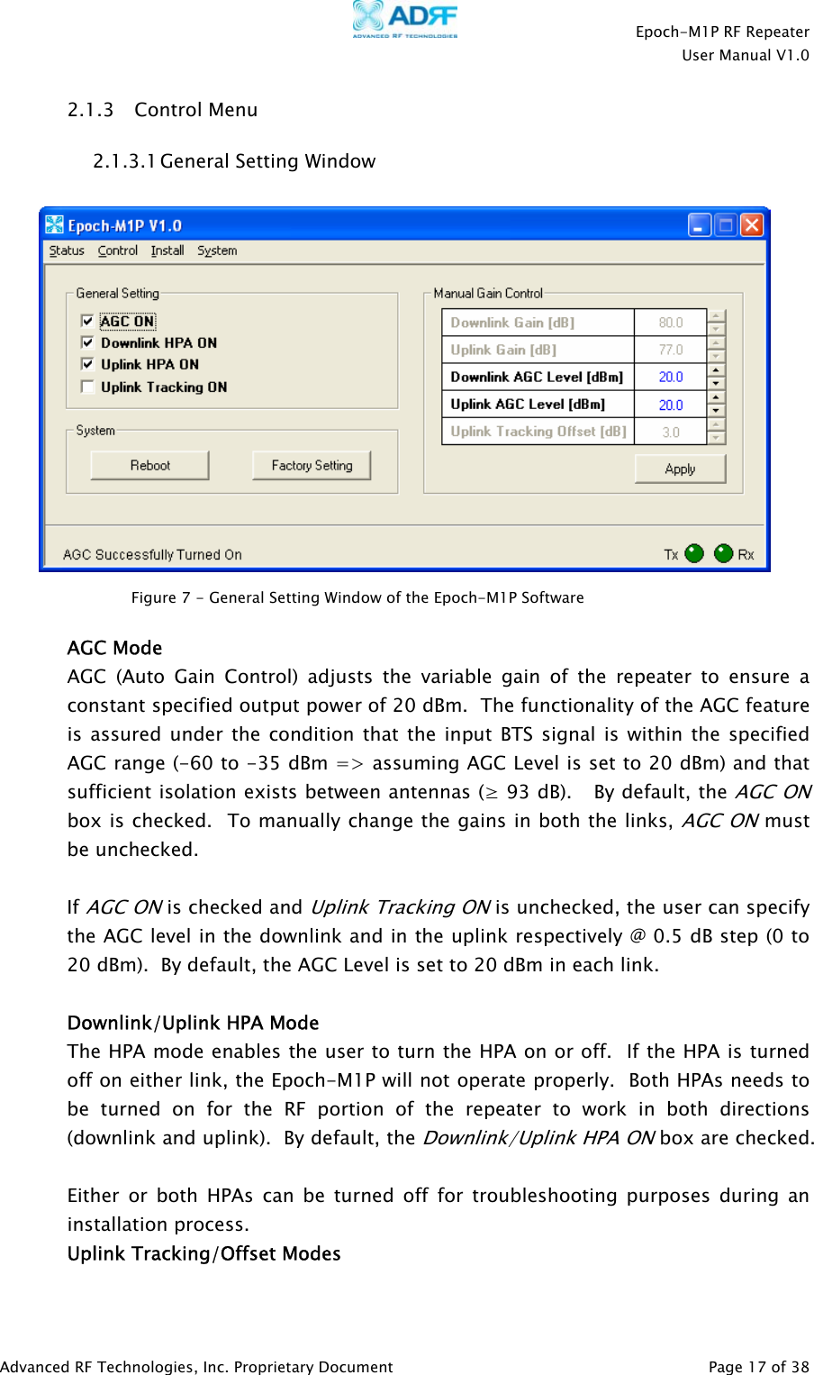
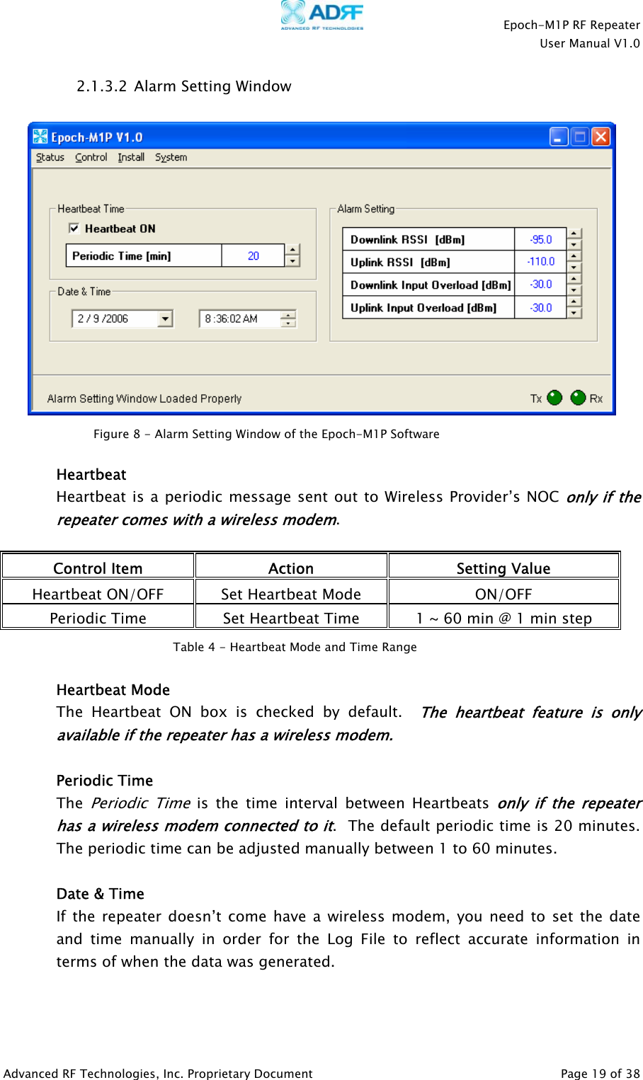
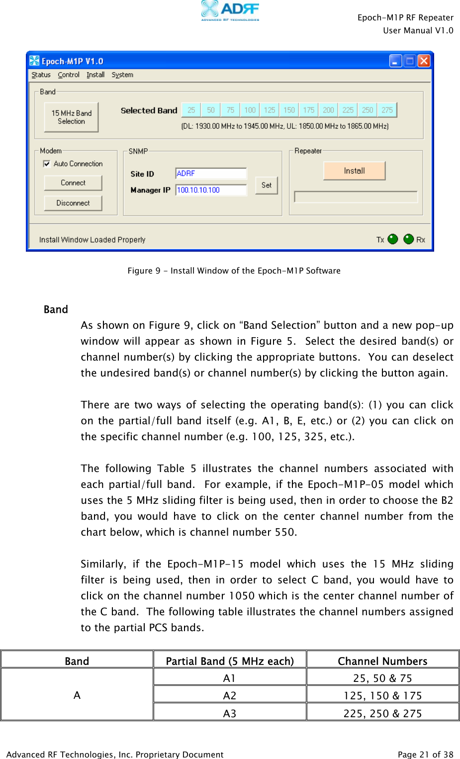
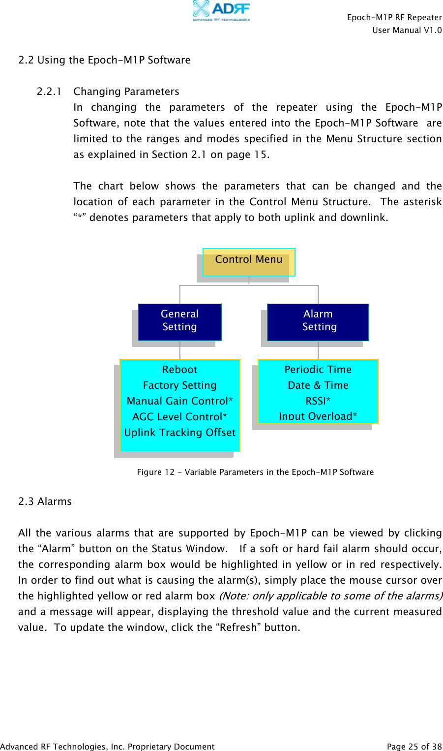
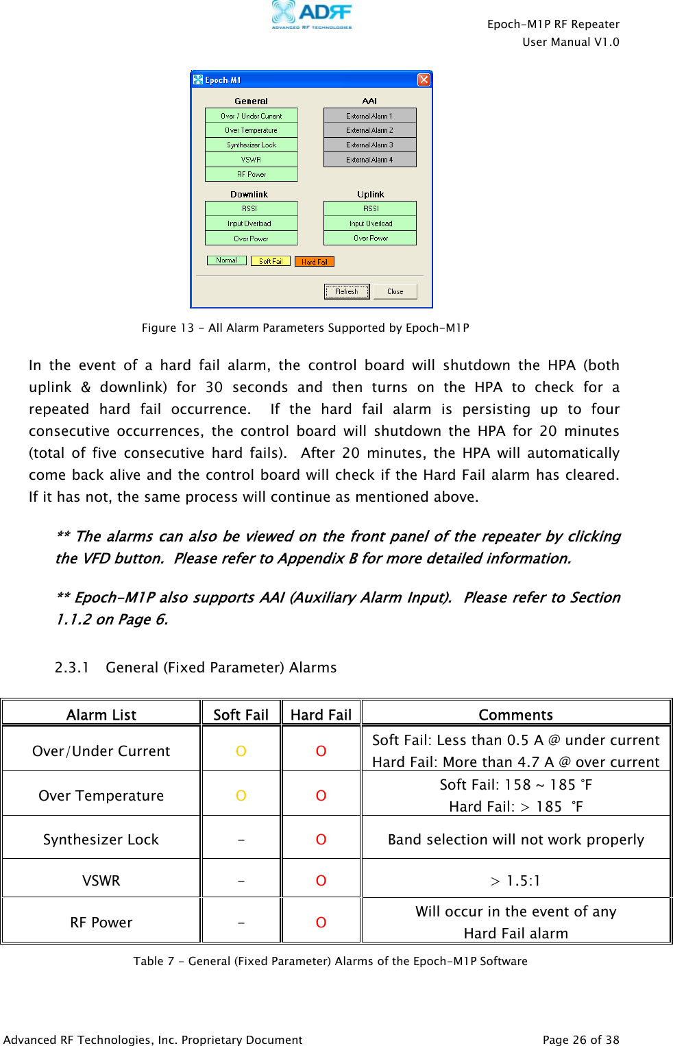
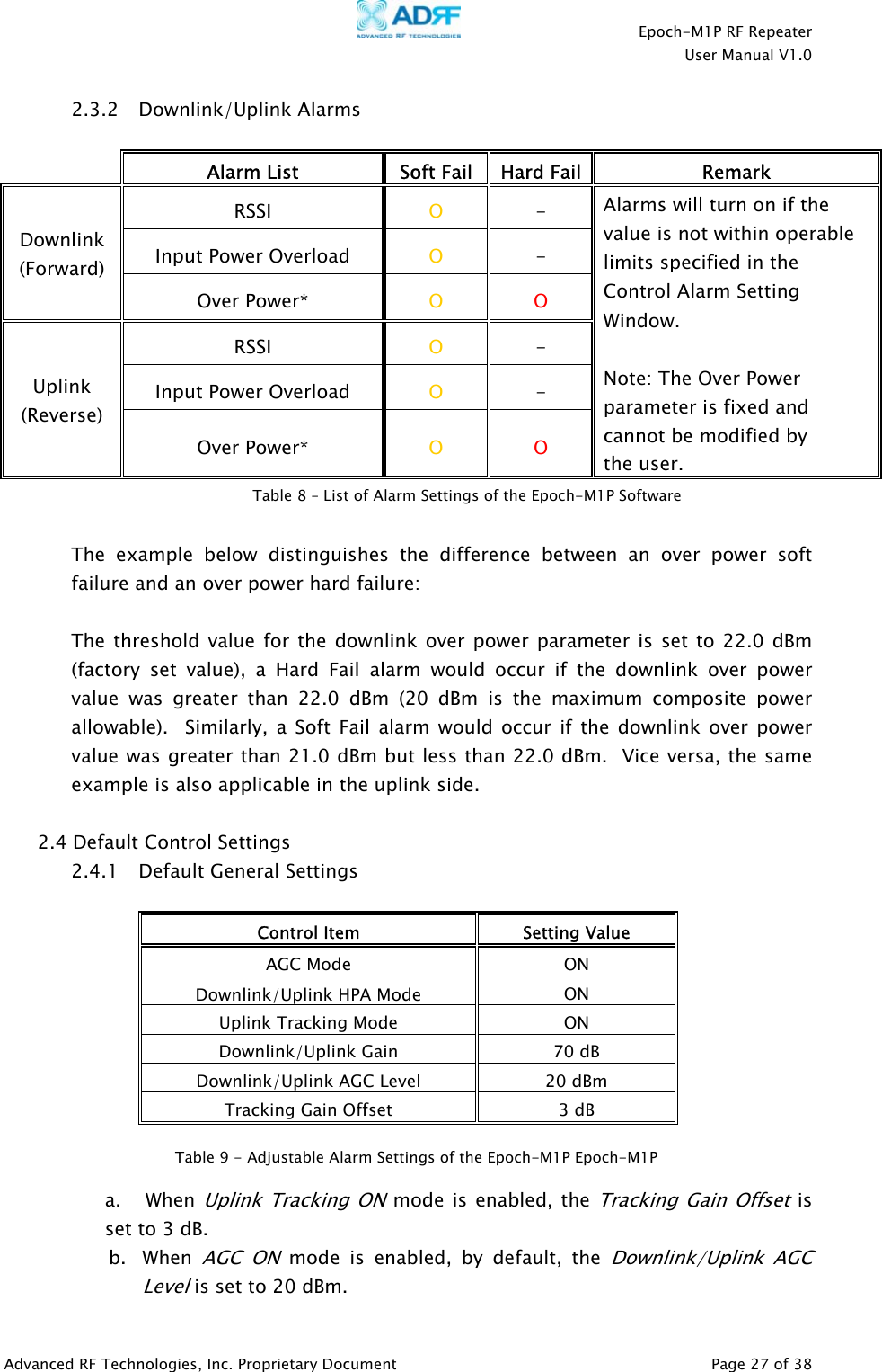
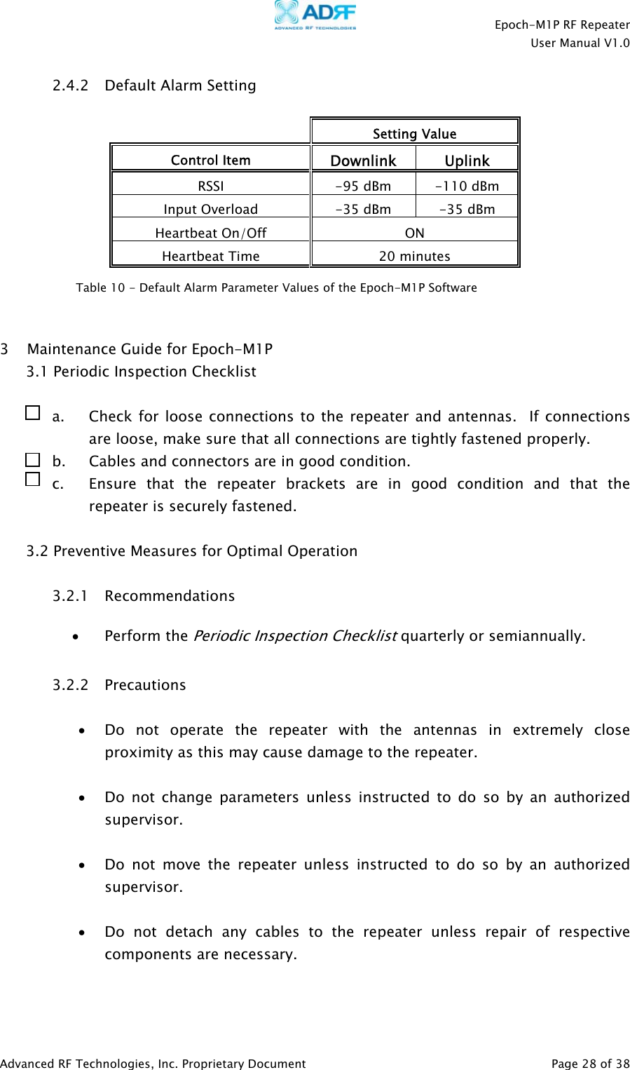
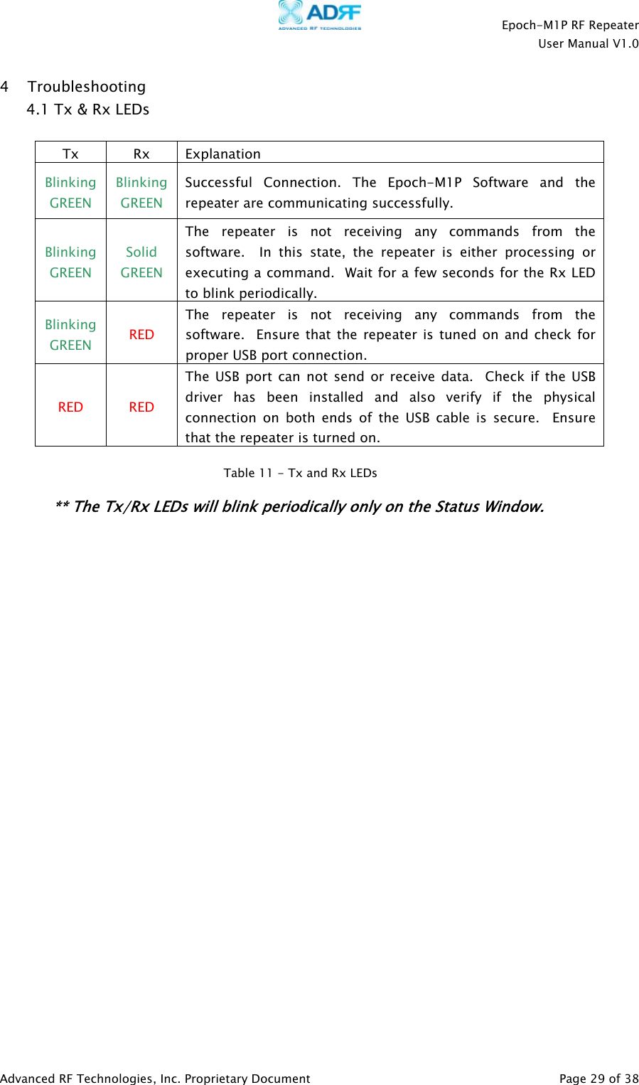
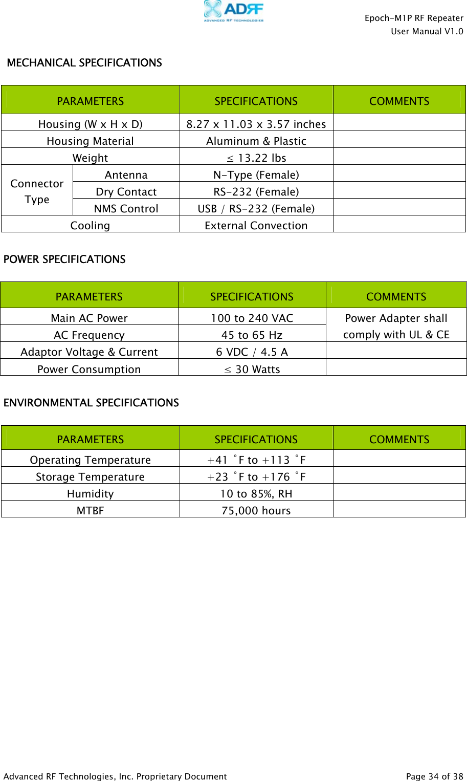
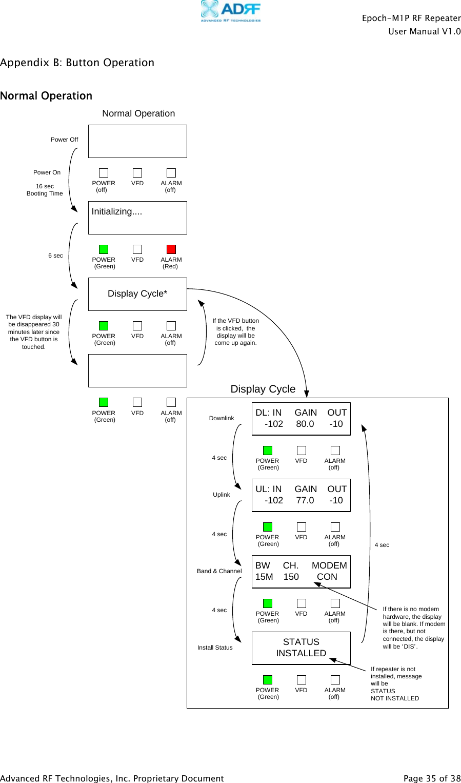
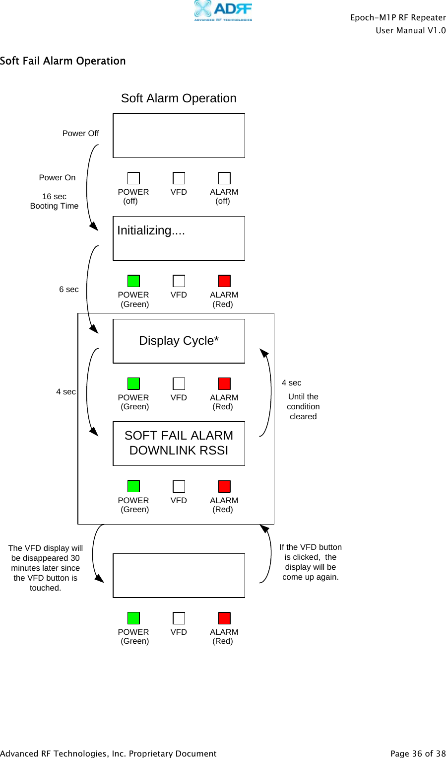
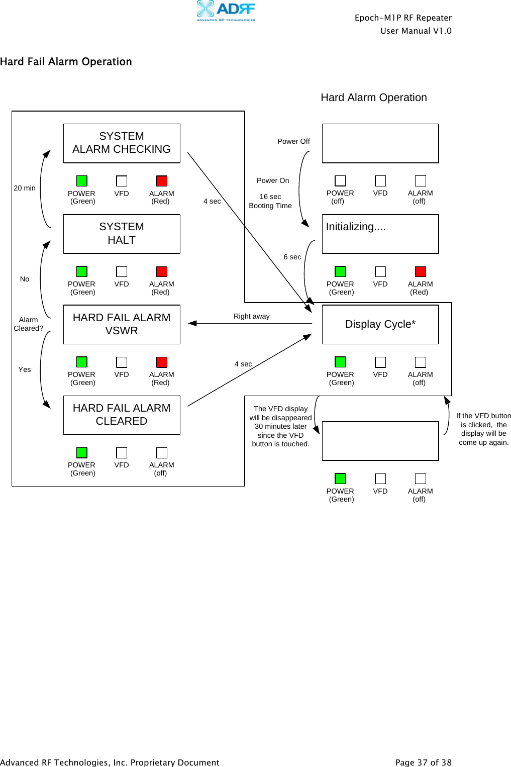
![Epoch-M1P RF Repeater User Manual V1.0 2.1.2 Status Window The Status Window is the monitoring window of the Epoch-M1P Software. This window enables the user to monitor the status and settings of the Epoch-M1P. In other words, no parameters can be changed in the Status Window. To change parameters, you will need to go to the Control Window. Band Selection Currently selected band(s) are highlighted. Repeater Input Indicates input signal strength of the repeater after the donor antenna [in dBm]. Repeater Output The output of the repeater [in dBm] before being radiated by the server antenna. Repeater Gain Indicates the gain of the repeater [in dB]. Alarm Button The alarm button changes color to the corresponding status of the repeater: Green for normal operation; Yellow for soft fail alarm; and Red for hard fail alarm. Click on the alarm button for detailed alarm information. Message Board The user will be able to see heartbeat messages which are sent out recently. In addition, the user will also be able to see any alarms that are generated along with messages once the alarms are cleared as well. Figure 6 - Status Window of the Epoch-M1P Software Center Channel Number Indicates the center channel number of the selected band. Modem Connection If the modem has properly established a PPP session. Clear Will clear the Message Board. Log File History for the heartbeats and alarms generated from the repeater and can be saved as a text file. Status Bar Displays the status of the repeater (e.g. Status Window Loaded Properly, etc.), transmit (TX) and receive (RX) communication LEDs. Installation Will let you know if the repeater is properly installed. Advanced RF Technologies, Inc. Proprietary Document Page 16 of 38](https://usermanual.wiki/Advanced-RF-Technologies/ADRFTECH003.Users-Manual/User-Guide-656742-Page-16.png)