Advanced RF Technologies ADRFTECH003 Epoch- M1P Repeater User Manual 1
Advanced RF Technologies, Inc. Epoch- M1P Repeater 1
Contents
Users Manual


Epoch-M1P RF Repeater
User Manual V1.0
Version 1.0 (Released May 4, 2006)
Information in this document is subject to change without notice.
Advanced RF Technologies, Inc. 1996-2006. All rights reserved.
Please send comments to:
E-Mail: info@adrftech.com
Phone: (323) 254-8131
Fax: (323) 254-4928
Address: Advanced RF Technologies, Inc.
Attention: Technical Publications Department
2607 Colorado Blvd., Suite 100
Los Angeles, CA 90041
USA
www.adrftech.com
Advanced RF Technologies, Inc. Proprietary Document Page 2 of 38

Epoch-M1P RF Repeater
User Manual V1.0
TABLE OF CONTENTS
1. Introduction of Epoch-M1P.................................................................................5
1.1 Overview ......................................................................................................5
1.1.1 Highlights ......................................................................................5
1.1.2 Special Features..............................................................................5
1.1.3 Available Models ............................................................................7
1.2 Warnings and Hazards ..................................................................................8
1.3 Epoch-M1P Parts List....................................................................................9
1.4 Software Installation and Requirements .....................................9 Epoch-M1P
1.4.1 Minimum Requirements ....................................................................9
1.4.2 Software Installation ....................................................10Epoch-M1P
1.4.3 Initial Startup of Software ............................................10 Epoch-M1P
1.5 Pre-Installation using Epoch-M1P Software ................................................10
1.6 Step by Step Instructions for Installation .....................................................11
1.6.1 Repeater Setup .............................................................................11
2 User Manual V1.0 using Epoch-M1P Software ....................................................15
2.1 Menu Structure ...........................................................................................15
2.1.1 Window Menu...............................................................................15
2.1.2 Status Menu .................................................................................16
2.1.3 Control Menu ...............................................................................17
2.1.3.1 General Setting Window..................................................17
2.1.3.2 Alarm Setting Window ....................................................19
2.1.4 Install Menu..................................................................................20
2.1.5 System Menu................................................................................23
2.1.5.1 Info. Window ..................................................................23
2.1.5.2 Upgrade Window ............................................................24
2.2 Using the Epoch-M1P Software ..................................................................25
2.2.1 Changing Parameters ...................................................................25
2.3 Alarms........................................................................................................25
2.3.1 General (Fixed Parameter) Alarms .................................................26
2.3.2 Downlink/Uplink Alarms...............................................................27
2.4 Default Control Settings..............................................................................27
2.4.1 Default General Setting.................................................................27
2.4.2 Default Alarm Setting ...................................................................28
3 Maintenance Guide for Epoch-M1P ....................................................................28
3.1 Periodic Inspection Checklist ......................................................................28
3.2 Preventive Measures for Optimal Operation.................................................28
3.2.1 Recommendations ........................................................................28
3.2.2 Precautions ..................................................................................28
4 Troubleshooting ................................................................................................29
4.1 Tx & Rx LEDs..............................................................................................29
Advanced RF Technologies, Inc. Proprietary Document Page 3 of 38

Epoch-M1P RF Repeater
User Manual V1.0
4.2 Common Installation Problems ...................................................................30
5 Warranty and Repair Policy.................................................................................31
5.1 General Warranty ........................................................................................31
5.2 Limitations of Warranty...............................................................................31
5.3 Limitation of Damages ...............................................................................31
5.4 No Consequential Damages........................................................................31
5.5 Additional Limitation on Warranty...............................................................31
5.6 Return Material Authorization (RMA)...........................................................32
Appendix A: Specifications ..........................................................................................33
Appendix B: Button Operation......................................................................................35
Advanced RF Technologies, Inc. Proprietary Document Page 4 of 38
Epoch-M1P RF Repeater
User Manual V1.0
1. Introduction of Epoch-M1P
1.1 Overview
Epoch-M1P series repeaters enhances in-building wireless coverage in the most
effective and cost efficient way. For its intelligent design and versatility, Epoch-
M1P series repeaters is the ideal choice for wireless coverage problems indoors.
Epoch-M1P series repeaters can be used as a stand-alone repeater with passive
antennas connected to it or it can also be used as a feeder repeater to a DAS
(Distributed Antenna System).
1.1.1
1.1.2
Highlights
• 20 dBm Composite Output Power
• 80 dB gain
• 25 dB AGC Range @ 0.5 dB Step
• Can Set AGC Output Power Level
• Band/Channel Selectable via Software
• Can Support Non-Contiguous Bands
• Supports Embedded Wireless Modem
• Supports Network Management Monitoring System via SNMP
• Supports Auxiliary Alarming for a DAS or a Third-Party Repeater
Special Features
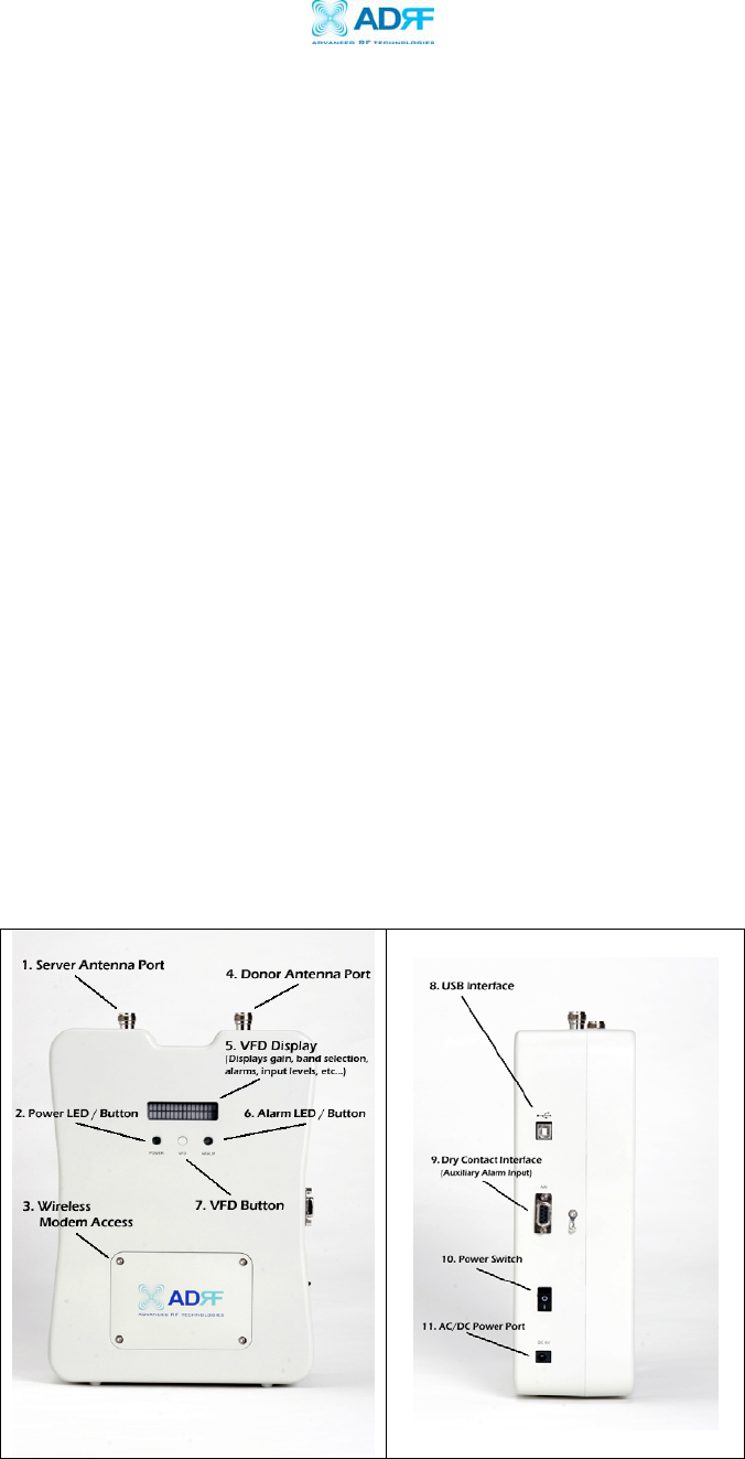
Figure 1 – Front & Right Side Views of the Repeater
Advanced RF Technologies, Inc. Proprietary Document Page 5 of 38

Epoch-M1P RF Repeater
User Manual V1.0
1. Server Antenna Port
One end of the coax cable will connect to the “Server Antenna Port” of
Epoch-M1P while the other end of the cable will connect to the server
antenna which is pointing towards the intended coverage area.
2. Power LED / Button
The Power LED will be lit Green if the power is turned on and will be not
lit if the power is turned off.
3. Wireless Modem Access
You can manually place or take off the wireless modem by taking of the
four screws.
4. Donor Antenna Port
One end of the coax cable will connect to the “Donor Antenna Port” of
Epoch-M1P while the other end of the cable will connect to the donor
antenna which is pointing towards the BTS.
The coax cable coming in from the donor antenna (pointing towards the
BTS)
5. VFD Display
In this display, you are able to view the repeater vitals in each link (e.g.
RSS, Gain, Output Power & Alarms).
6. Alarm LED / Button
If there’s an alarm, the Alarm LED will be lit Red and will not be lit if there
isn’t any alarm.
At the same time, by pressing the “Alarm LED” button, you can choose the
desired operating band(s). By clicking on the “ALARM LED” button each
time, you will be sliding the filter (5, 10 or 15 MHz - depending on the
Epoch-M1P model) to the right side of the spectrum by an increment of
25 channel steps (1.25 MHz bandwidth).
**
t
Please refer to Appendix B for more detailed information on how the
Alarm LED but ons operates.
Advanced RF Technologies, Inc. Proprietary Document Page 6 of 38

Epoch-M1P RF Repeater
User Manual V1.0
7. VFD
VFD stands for “Vacuum Fluorescent Display.”
** Please refer to Appendix B for more detailed information on how the
VFD button operates.
8. USB Interface
For management and troubleshooting purposes, you can connect your PC
to Epoch-M1P via USB cable.
9. Dry Contact Interface (AAI)
AAI stands for Auxiliary Alarm Input. It acts as the interface between the
two devices (Epoch-M1P & DAS or third-party repeater) so that it can pass
alarming information from the third-party device to the Epoch-M1P. The
following table illustrates the PIN assignment which can be customized
according to the third-party device so that proper alarming parameters
are passed to Epoch-M1P.
No. NAME Description
1 Cable Connection Active Low
2 External Alarm 1 Active Low
3 External Alarm 2 Active Low
4 External Alarm 3 Active Low
5 External Alarm 4 Active Low
6 GND GND
7 GND GND
8 Open Open
9 Open Open
Table 1 – Pin Assignment for AAI
1.1.3 Available Models
Epoch-M1P is available in all 1900 MHz PCS band combinations. The
following table illustrates the four standard models:
Product ID Description
Epoch-M1P-05 RF repeater with 5 MHz sliding filter @ 0.5
dB step across the 60 MHz PCS spectrum
Epoch-M1P-10 RF repeater with 10 MHz sliding filter @ 0.5
dB step across the 60 MHz PCS spectrum
Epoch-M1P-15 RF repeater with 15 MHz sliding filter @ 0.5
Advanced RF Technologies, Inc. Proprietary Document Page 7 of 38
Epoch-M1P RF Repeater
User Manual V1.0
dB step across the 60 MHz PCS spectrum
* Epoch-M1P-XX RF repeater with factory built fixed filters
Table 2 – Epoch-MIP Models
* In certain markets, service providers may be operating in non-
contiguous bands, e.g. D+E, A+C5, A3+D+C5, etc. In these special
markets, we are able to offer custom fixed filters to the service providers.
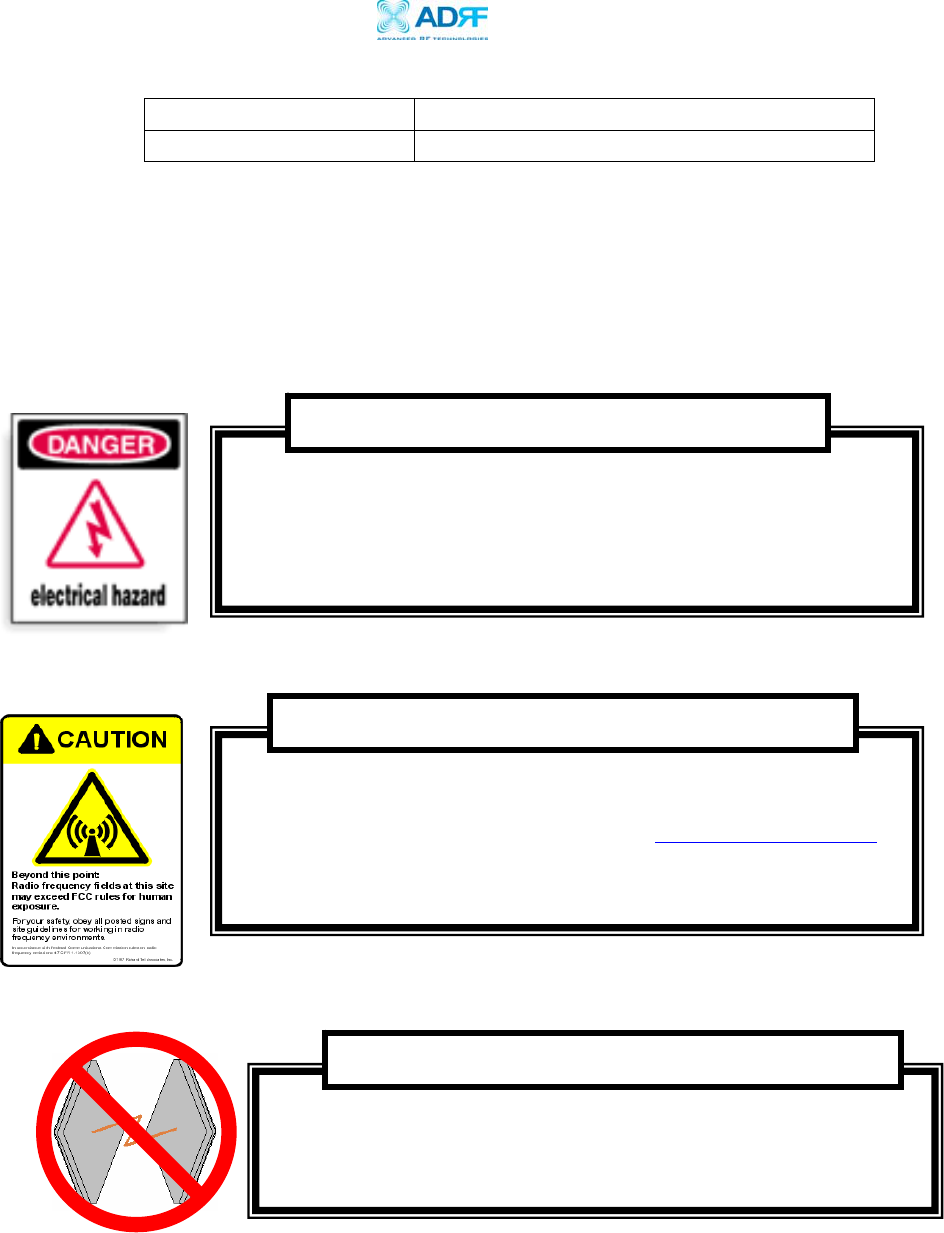
1.2 Warnings and Hazards
Operating the Epoch-M1P with antennas in very close proximity
facing each other could lead to severe damage to the repeater.
WARNING! DAMAGE TO REPEATER
Working with the repeater while in operation, may expose the
technician to RF electromagnetic fields that exceed FCC rules for
human exposure. Visit the FCC website at www.fcc.gov/oet/rfsafety
to learn more about the effects of exposure to RF electromagnetic
fields.
WARNING! EXPOSURE TO RF
Opening the Epoch-M1P could result in electric shock and may
cause severe injury.
WARNING! ELECTRIC SHOCK
Advanced RF Technologies, Inc. Proprietary Document Page 8 of 38
Epoch-M1P RF Repeater
User Manual V1.0
1.3 Epoch-M1P Parts List
The Epoch-M1P repeater system includes:
PART ID
QUANTITY
a. Epoch-M1P Repeater EPOCHMIPXX 1
b. Screws SC01 4
c. **CD M100OMS V1.XX01 1
d. USB Cable USB01 1
e. Power Cable PWRC01 1
** CD includes: (1) Software; (2) User Manual; (3) M1P Setup Quick Start Guide;
(4) USB Cable Setup Quick Start Guide; & (5) Software Setup Quick Start Guide.
1.4 Epoch-M1P Software Installation and Requirements
1.4.1 Minimum PCS Requirements
CPU: 200 MHz
Memory: 32 MB
Hard Disk: 10 MB (Free Space)
USB Port: 1 USB Port
CD-ROM Drive
Actual separation distance is determined upon gain of antenna used.
RF EXPOSURE & ANTENNA PLACEMENT Guidelines
Please maintain a minimum safe distance of at least 20 cm while operating near the
donor and the server antennas. Also, the donor antenna needs to be mounted
outdoors on a permanent structure.
Opening or tampering the Epoch-M1P will void all warranties.
WARRANTY
Advanced RF Technologies, Inc. Proprietary Document Page 9 of 38

Epoch-M1P RF Repeater
User Manual V1.0
Compatible Operating System:
Microsoft Windows 2000 / XP
1.4.2 Epoch-M1P Software Installation
** Refer to the Software Setup Guide
1.4.3 Initial Startup of Epoch-M1P Software
a. Using the USB cable (USB01) that is provided, connect one end of the
cable to the USB port to the PC and the other end to the repeater’s
USB port located on the right side of the repeater.
b. Open the Epoch-M1P Software.
** Refer to the USB Setup Guide
1.5 Pre-Installation using Epoch-M1P Software
Prior to the Epoch-M1P installation, ensure that:
a. The USB cable has been connected and proper communication has
been established.
b. The donor and server antennas are in place.
c. The TX and RX communication status LEDs are lit green and blinking
periodically on the Status Menu.
** The TX and RX LEDs should blink every 1 second only in the Status
Menu. In the Status Menu, a blinking green RX LED indicates that the PC
is retrieving data from the repea er (Epoch-M1P). Similarly, a blinking
green TX LED indicates that the PC is transmitting data to the Epo h-M1P.
t
c
Advanced RF Technologies, Inc. Proprietary Document Page 10 of 38
Epoch-M1P RF Repeater
User Manual V1.0
1.6 Step by Step Instructions for Installation
Repeater Setup
1.6.1
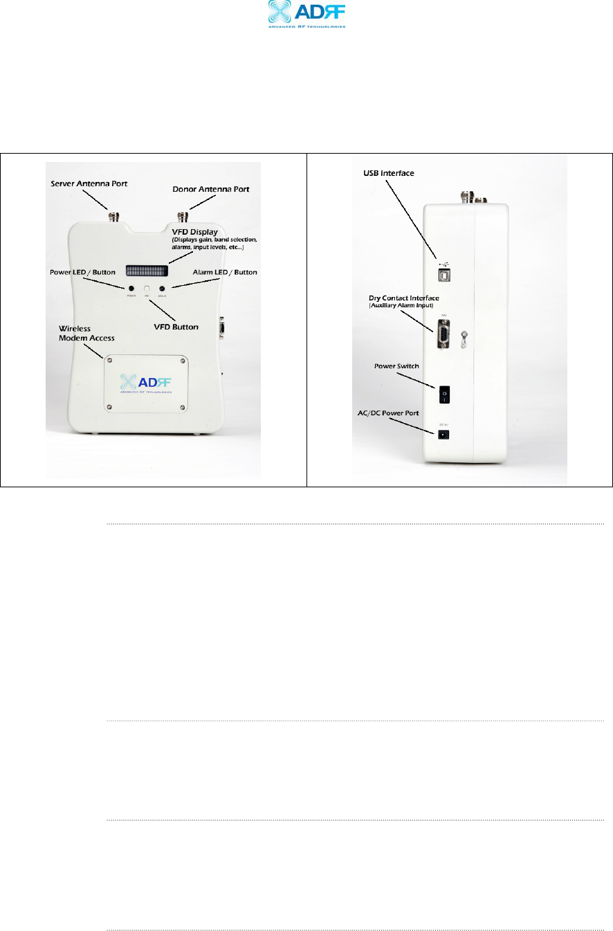
Figure 2 – Front & Right Side Views of the Repeater
1. Connect the Power Source
Make sure that the power switch on the right side of the repeater is
turned off before connecting the power cable. Connect the power cable
to the AC/DC Power Port as shown in Figure 3. Make sure not to turn the
power on
** Before connecting the power cable to the power source, make sure that
the voltage source is 110 V.
2. Connect the Donor Antenna
Connect one end of the RF coaxial cable to the donor antenna and the
other end to the repeater Donor Antenna Port located on the top of the
Epoch-M1P as shown in Figure 2.
6. Connect the Server Antenna
Connect one end of the RF coaxial cable to the server antenna and
connect the other end to the repeater Server Antenna Port located on the
top of the Epoch-M1P as shown in Figure 2.
7. Connect the USB Cable
Advanced RF Technologies, Inc. Proprietary Document Page 11 of 38
Epoch-M1P RF Repeater
User Manual V1.0
Using the USB cable (included in the box), connect one end of the cable to
the Epoch-M1P’s USB port located on the right side of the repeater and
the other end to the PC’s USB port as shown in Figure 2.
** Install the USB driver and the Epoch-M1P Manager Software prior to
installation.
8. Turn On the Power for Epoch-M1P
Make sure that the donor and server antennas and the power cable are
securely connected to the correct ports. Turn the power switch on,
located on the right side of the repeater.
9. Launch the Epoch-M1P Software
Open the Epoch-M1P Software. You will see the Status Menu.
** For more detailed information on the Epoch-M1P Sof ware, please
refer to Section 2 on page 15.
t
r t
** If only one o bo h of the LEDs are not blinking: (1) check the physical
USB cable connection or (2) check if the repeater power is turned on.
10. Go to the Install Window
Now with the blinking TX and RX status LEDs on the Status Window, go to
the Install Window. You will see the following:
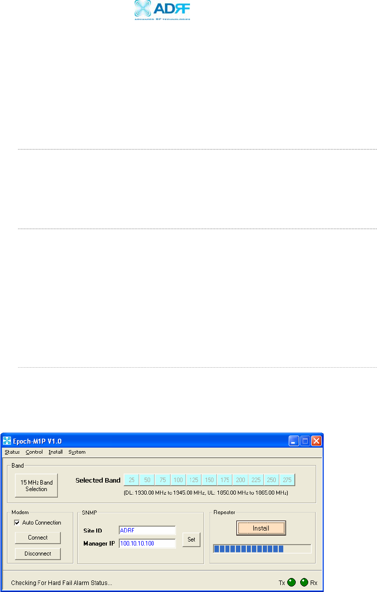
Figure 3 - Installation Window of the Epoch-M1P Software
Advanced RF Technologies, Inc. Proprietary Document Page 12 of 38
Epoch-M1P RF Repeater
User Manual V1.0
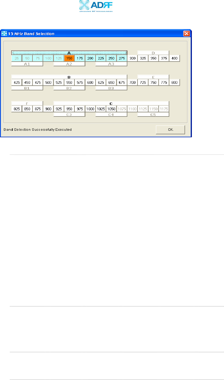
Figure 4 – Band Selection Window of the Epoch-M1P Software
11. Select the Desired Band(s)
From the Install Window (Figure 3), click on “XX MHz Band Selection”
button and a new pop-up window will appear (Figure 4). Select the
desired band(s) or center channel number(s) by clicking the appropriate
buttons. You can deselect the undesired band(s) or channel number(s) by
clicking the button again.
There are two ways of selecting the operating band(s): (1) you can click
on the partial/full band itself (e.g. A1, B, E, etc.) or (2) you can click on
the specific channel #’s (e.g. 100, 125, 325, etc.).
** Depending on whi h model of Epoch-M1P is being used, the band
selection window will vary.
c
** If a wireless modem is not connected, skip steps 12 through 13 and
proceed to step 14.
12. Provide SNMP Information
Type in the Site ID and the Manager IP address as given to you by the
Wireless Provider. Once both the parameters are typed in, you must click
“Set” for it to be executed.
13. Check the Modem Connection
Verify that the
Auto Connection
box is checked.
14. Click on Install
After the first three steps, click on “Install.” This installation process will
normally take less than a minute.
Advanced RF Technologies, Inc. Proprietary Document Page 13 of 38
Epoch-M1P RF Repeater
User Manual V1.0
** Please refer to the “M1P Setup Guide” for any questions or problems
that you may encounter during this installation process.
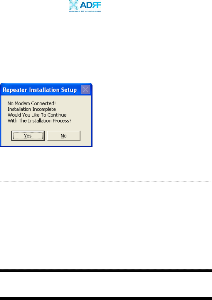
If a modem is not connected to the repeater and you click the “Install”
button, the following pop-up window will appear:
If you choose to continue with the RF portion only, simply click “Yes” and
the installation process will resume again.
16. Check the Front LED Panel
Check that the Power LED is on (Green) and the Alarm LED (Red) is off.
** If the Alarm LED is on, refer to Sec ion 2.3 on page 25. t
** You can go to the Status Menu of the Epoch-M1P Software to view the
basic parameters of the repeater once the repeater has installed
successfully.
CONGRATULATIONS!!
The Epoch-M1P Installation Process is Complete.
Advanced RF Technologies, Inc. Proprietary Document Page 14 of 38
Epoch-M1P RF Repeater
User Manual V1.0
2 User Manual V1.0 using Epoch-M1P Software
2.1 Menu Structure
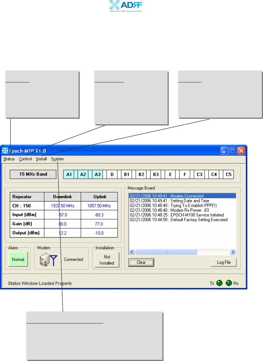
2.1.1 Window Overview
Status
The Status Window allows
you to monitor the current
settings and status of the
Epoch-M1P.
Control
The Control Window enables
you to change or adjust the
Epoch-M1P’s parameters
and settings.
Install
The Install Window guides you
through an automated
installation of the Epoch-M1P
repeater.
System Information
For more detailed system information, click on the
Info. Menu. Information such as model number,
serial number, firmware version and manufacturing
date of the repeater are included here.
Figure 5 - Status Window of the Epoch-M1P Software
Advanced RF Technologies, Inc. Proprietary Document Page 15 of 38
Epoch-M1P RF Repeater
User Manual V1.0
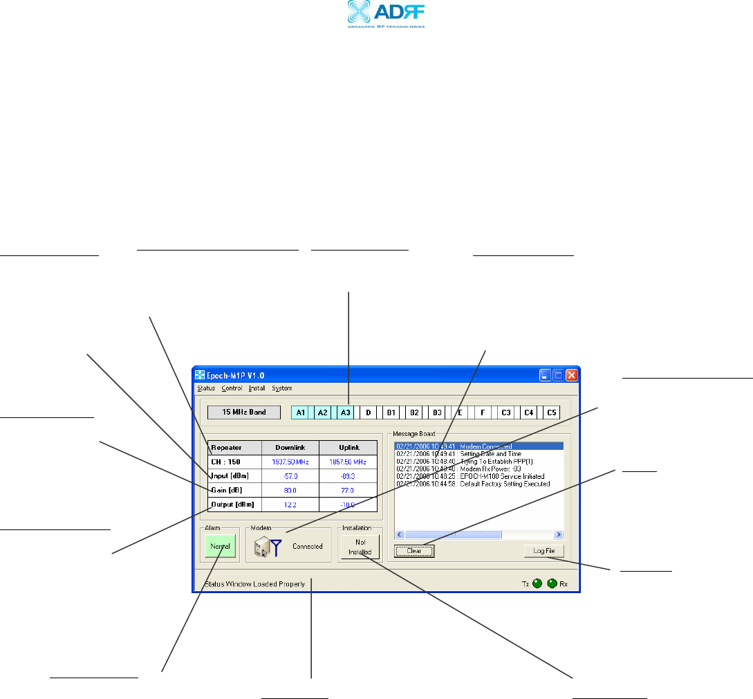
2.1.2 Status Window
The Status Window is the monitoring window of the Epoch-M1P Software.
This window enables the user to monitor the status and settings of the
Epoch-M1P. In other words, no parameters can be changed in the Status
Window. To change parameters, you will need to go to the Control
Window.
Band Selection
Currently selected
band(s) are highlighted.
Repeater Input
Indicates input
signal strength of
the repeater after
the donor antenna
[in dBm].
Repeater Output
The output of the
repeater [in dBm]
before being radiated
by the server antenna.
Repeater Gain
Indicates the gain
of the repeater
[in dB].
Alarm Button
The alarm button changes color
to the corresponding status of
the repeater: Green for normal
operation; Yellow for soft fail
alarm; and Red for hard fail
alarm. Click on the alarm
button for detailed alarm
information.
Message Board
The user will be able to see heartbeat messages
which are sent out recently. In addition, the user
will also be able to see any alarms that are
generated along with messages once the alarms are
cleared as well.
Figure 6 - Status Window of the Epoch-M1P Software
Center Channel Number
Indicates the center
channel number of the
selected band.
Modem Connection
If the modem has properly
established a PPP session.
Clear
Will clear the
Message Board.
Log File
History for the
heartbeats and alarms
generated from the
repeater and can be
saved as a text file.
Status Bar
Displays the status of the repeater (e.g. Status
Window Loaded Properly, etc.), transmit (TX)
and receive (RX) communication LEDs.
Installation
Will let you know if the
repeater is properly
installed.
Advanced RF Technologies, Inc. Proprietary Document Page 16 of 38
Epoch-M1P RF Repeater
User Manual V1.0
2.1.3 Control Menu
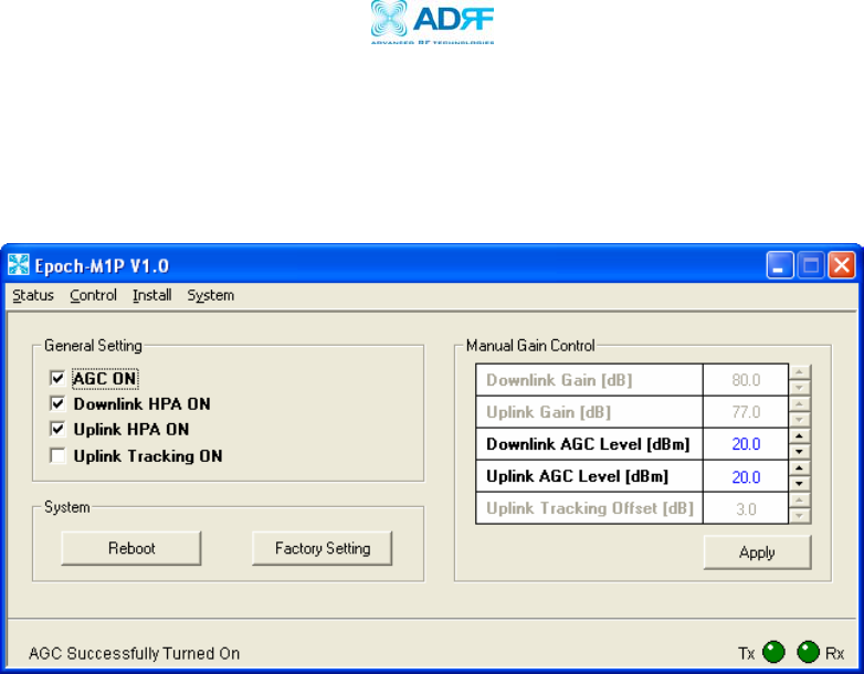
2.1.3.1 General Setting Window
Figure 7 - General Setting Window of the Epoch-M1P Software
AGC Mode
AGC (Auto Gain Control) adjusts the variable gain of the repeater to ensure a
constant specified output power of 20 dBm. The functionality of the AGC feature
is assured under the condition that the input BTS signal is within the specified
AGC range (-60 to -35 dBm => assuming AGC Level is set to 20 dBm) and that
sufficient isolation exists between antennas (≥ 93 dB). By default, the
AGC ON
box is checked. To manually change the gains in both the links,
AGC ON
must
be unchecked.
If
AGC ON
is checked and
Uplink Tracking ON
is unchecked, the user can specify
the AGC level in the downlink and in the uplink respectively @ 0.5 dB step (0 to
20 dBm). By default, the AGC Level is set to 20 dBm in each link.
Downlink/Uplink HPA Mode
The HPA mode enables the user to turn the HPA on or off. If the HPA is turned
off on either link, the Epoch-M1P will not operate properly. Both HPAs needs to
be turned on for the RF portion of the repeater to work in both directions
(downlink and uplink). By default, the
Downlink/Uplink HPA ON
box are checked.
Either or both HPAs can be turned off for troubleshooting purposes during an
installation process.
Uplink Tracking/Offset Modes
Advanced RF Technologies, Inc. Proprietary Document Page 17 of 38

Epoch-M1P RF Repeater
User Manual V1.0
Uplink tracking mode enables or disables the
Uplink Tracking ON
feature that
sets the gain in the uplink equaling to the gain in the downlink. The tracking
gain offset is the difference in the uplink and downlink gains. For example, if
the downlink gain is 80 dB, the
Uplink Tracking ON
is checked, and the
Uplink
Tracking Gain Offset
is set to 3 dB, the uplink gain would be 77 dB.
r
By default, the
Uplink Tracking ON
box is not checked. If it was checked, then
the default
Uplink T acking Offset
is set to 3 dB. This means that the uplink gain
will track the down link gain and will be 3 dB less.
Control Item Action Setting Value
Uplink Tracking ON Set Uplink Tracking Mode ON or OFF
Uplink Tracking Offset Set Tracking Gain Offset 0 ~ 10 dB @ 0.5 dB step
Table 3 - Uplink Tracking Mode and Tracking Gain Offset Range
Downlink/Uplink Gain
The gain of the Epoch-M1P is the ratio of the input signal to the output signal.
The gain may be set in both links.
** The manual gain option is disabled when the AGC ON box is checked.
Reboot
By clicking the “Reboot” button, similar to how the operation works in a PC, the
control board of the repeater will restart itself.
Factory Setting
Clicking on the “Factory Setting”
button resets the settings of the repeater to the
original default factory settings as noted in the “Default Control Settings” in
Section 2.4 on page 28.
** You will lose your current saved settings once you click on Factory Setting.
Advanced RF Technologies, Inc. Proprietary Document Page 18 of 38
Epoch-M1P RF Repeater
User Manual V1.0
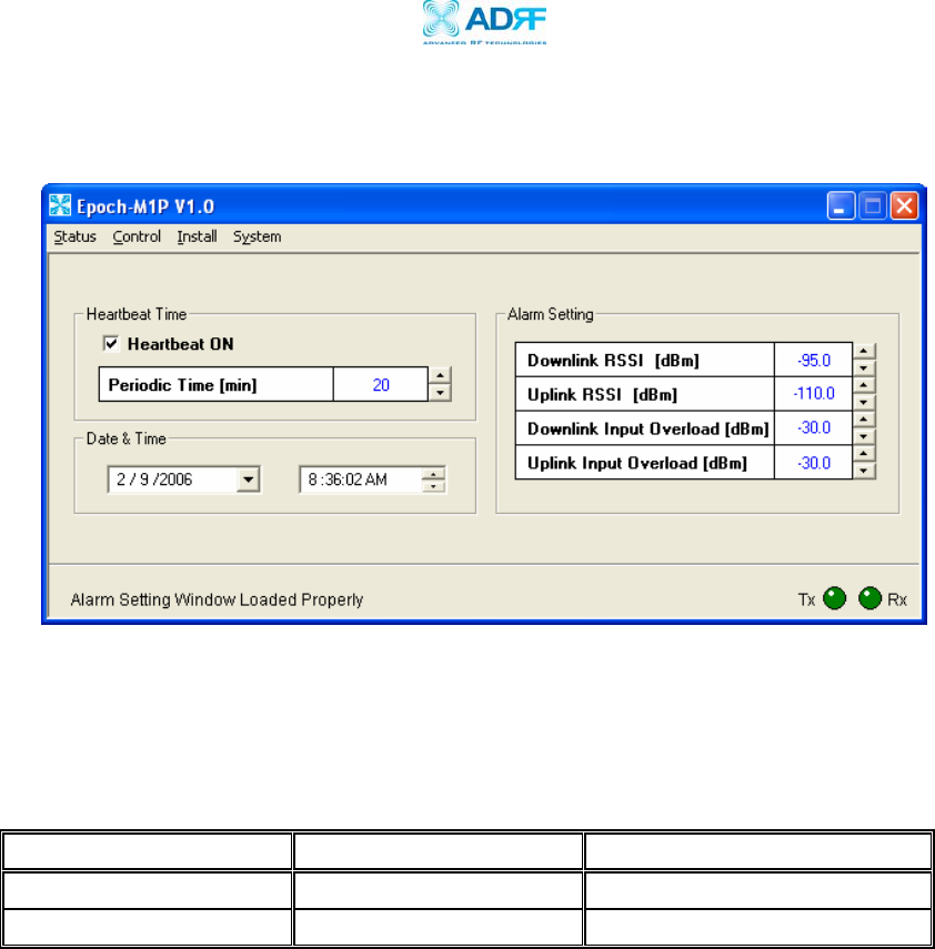
2.1.3.2 Alarm Setting Window
Figure 8 - Alarm Setting Window of the Epoch-M1P Software
Heartbeat
Heartbeat is a periodic message sent out to Wireless Provider’s NOC
only if the
repeater comes with a wireless modem
.
Control Item Action Setting Value
Heartbeat ON/OFF Set Heartbeat Mode ON/OFF
Periodic Time Set Heartbeat Time 1 ~ 60 min @ 1 min step
Table 4 - Heartbeat Mode and Time Ran
g
e
Heartbeat Mode
The Heartbeat ON box is checked by default.
The heartbeat feature is only
available if the repeater has a wireless modem.
Periodic Time
The
Periodi Time
is the time interval between Heartbeats
only if the repeater
has a wireless modem connected to it
. The default periodic time is 20 minutes.
The periodic time can be adjusted manually between 1 to 60 minutes.
c
Date & Time
If the repeater doesn’t come have a wireless modem, you need to set the date
and time manually in order for the Log File to reflect accurate information in
terms of when the data was generated.
Advanced RF Technologies, Inc. Proprietary Document Page 19 of 38

Epoch-M1P RF Repeater
User Manual V1.0
If there’s a modem inside the repeater, you don’t need to set the date and time
manually.
Alarm Setting
RSSI
The RSSI alarm is the minimum RSSI value that the Epoch-M1P requires to ensure
optimal coverage. The RSSI alarm will go off when the RSSI is lower than the
threshold value (refer to the RSSI value in the Alarm Setting Window). The
threshold RSSI value can also be adjusted manually @ 0.5 dB step (range is
shown in Table 5 on page 20).
Input Overload
A Downlink/Uplink Input Overload alarm occurs when the input signal strength
to the Epoch-M1P exceeds the threshold value (refer to the Uplink/Downlink
Input
Overload values in the Alarm Setting window).
Control Item Action Downlink Uplink
Downlink/Uplink RSSI Sets Low RSSI Alarm Level -110 ~ -80 dBm -110 ~ -80 dBm
Downlink/Uplink
Input Overload Sets Input Overload Level -45 ~ -20 dBm -45 ~ -20 dBm
Table 5 - Alarm Threshold Values
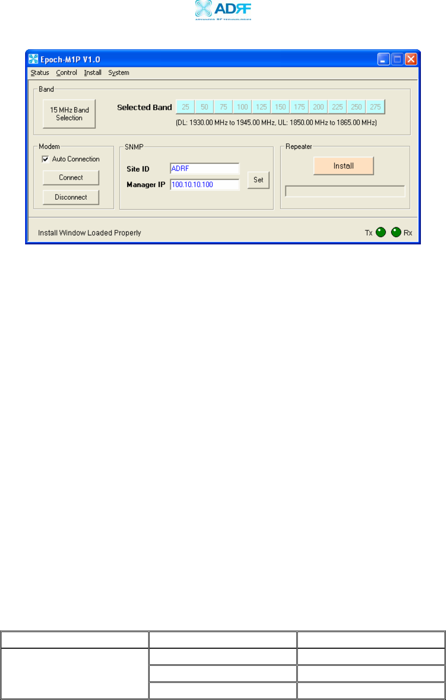
2.1.4 Install Window
At the time of installation, the installer needs to go to the Install Window of the
Epoch-M1P Software. The Install Window will guide the installer through a step
by step process to properly install the Epoch-M1P repeater.
For setup or installation of Epoch-M1P, go to the Install
Window.
Advanced RF Technologies, Inc. Proprietary Document Page 20 of 38
Epoch-M1P RF Repeater
User Manual V1.0
Figure 9 - Install Window of the Epoch-M1P Software
Band
As shown on Figure 9, click on “Band Selection” button and a new pop-up
window will appear as shown in Figure 5. Select the desired band(s) or
channel number(s) by clicking the appropriate buttons. You can deselect
the undesired band(s) or channel number(s) by clicking the button again.
There are two ways of selecting the operating band(s): (1) you can click
on the partial/full band itself (e.g. A1, B, E, etc.) or (2) you can click on
the specific channel number (e.g. 100, 125, 325, etc.).
The following Table 5 illustrates the channel numbers associated with
each partial/full band. For example, if the Epoch-M1P-05 model which
uses the 5 MHz sliding filter is being used, then in order to choose the B2
band, you would have to click on the center channel number from the
chart below, which is channel number 550.
Similarly, if the Epoch-M1P-15 model which uses the 15 MHz sliding
filter is being used, then in order to select C band, you would have to
click on the channel number 1050 which is the center channel number of
the C band. The following table illustrates the channel numbers assigned
to the partial PCS bands.
Band Partial Band (5 MHz each) Channel Numbers
A1 25, 50 & 75
A2 125, 150 & 175
A
A3 225, 250 & 275
Advanced RF Technologies, Inc. Proprietary Document Page 21 of 38

Epoch-M1P RF Repeater
User Manual V1.0
D - 325, 350 & 375
B1 425, 450 & 475
B2 525, 550 & 575
B
B3 625, 650 & 675
E - 725, 750 & 775
F - 825, 850 & 875
C3 925, 950 & 975
C4 1025, 1050 & 1075
C
C5 1125, 1150 & 1175
Table 6 – Channel Number Assi
g
nment
SNMP
(only applicable if a wireless modem is connected to the repeate )
r
r
a. Site ID
The
Site ID
is a unique ID for each site and will be provided by the
Wireless Provider.
b. Manager IP
The
Manager IP
address will be provided by the Wireless Provider. The
repeater will send alarms to the Wireless Provider’s NOC to the assigned
Manager IP address.
Modem
(only applicable if a wireless modem is connected to the repeate )
The
Auto Connection
box needs to be checked when the wireless modem
is installed inside the repeater. A wireless modem is used in order to
send the alarms and the heartbeat over the air to the Wireless Provider’s
NOC.
Repeater
Click the “Install” button and the repeater will setup automatically.
For information regarding the use of the Epoch-M1P Software during installation,
refer to Section 1.7.1 on page 11, “Repeater Installation” (starting at number 9).
Advanced RF Technologies, Inc. Proprietary Document Page 22 of 38
Epoch-M1P RF Repeater
User Manual V1.0
2.1.5 System Menu
2.1.5.1 Info. Window
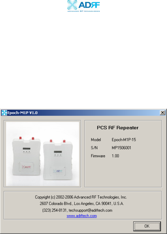
The Info. Window displays the Model Number, Serial Number and Firmware
Version of the Epoch-M1P repeater. Contact information is included along
with a link to Advanced RF Technologies, Inc.’s URL.
Figure 10 - Info. Window of the Epoch-M1P Software
Advanced RF Technologies, Inc. Proprietary Document Page 23 of 38
Epoch-M1P RF Repeater
User Manual V1.0
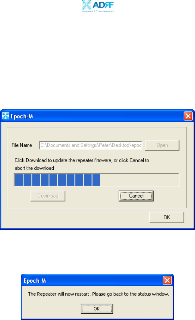
2.1.5.2 Upgrade Window
In order to download the latest repeater firmware, click on the Upgrade
Window. The firmware file will be provided by the technical support group
from Advanced RF Technologies, Inc. Once the firmware file has been saved
on the PC, you would connect the Epoch-M1P repeater to the PC via the USB
cable provided. Click on “Open” and locate the firmware file and click on
‘Download.”
Figure11 - Upgrade Window of the Epoch-M1P Software
Once the firmware has been downloaded successfully, the following pop-up
window will appear.
Advanced RF Technologies, Inc. Proprietary Document Page 24 of 38

Epoch-M1P RF Repeater
User Manual V1.0
2.2 Using the Epoch-M1P Software
2.2.1 Changing Parameters
In changing the parameters of the repeater using the Epoch-M1P
Software, note that the values entered into the Epoch-M1P Software are
limited to the ranges and modes specified in the Menu Structure section
as explained in Section 2.1 on page 15.
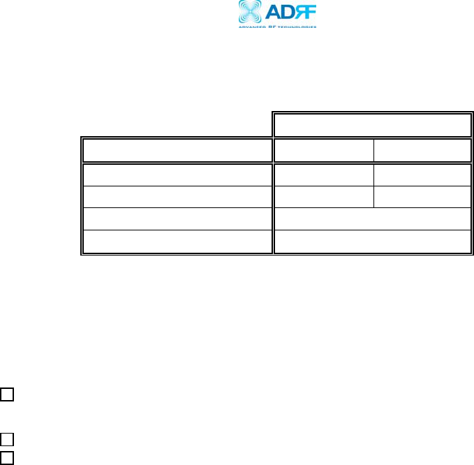
The chart below shows the parameters that can be changed and the
location of each parameter in the Control Menu Structure. The asterisk
“*” denotes parameters that apply to both uplink and downlink.
Control Menu
General Alarm
Setting Setting
Reboot Periodic Time
Factory Setting Date & Time
Manual Gain Control* RSSI*
Input Overload
*
AGC Level Control*
Uplink Tracking Offset
Figure 12 - Variable Parameters in the Epoch-M1P Software
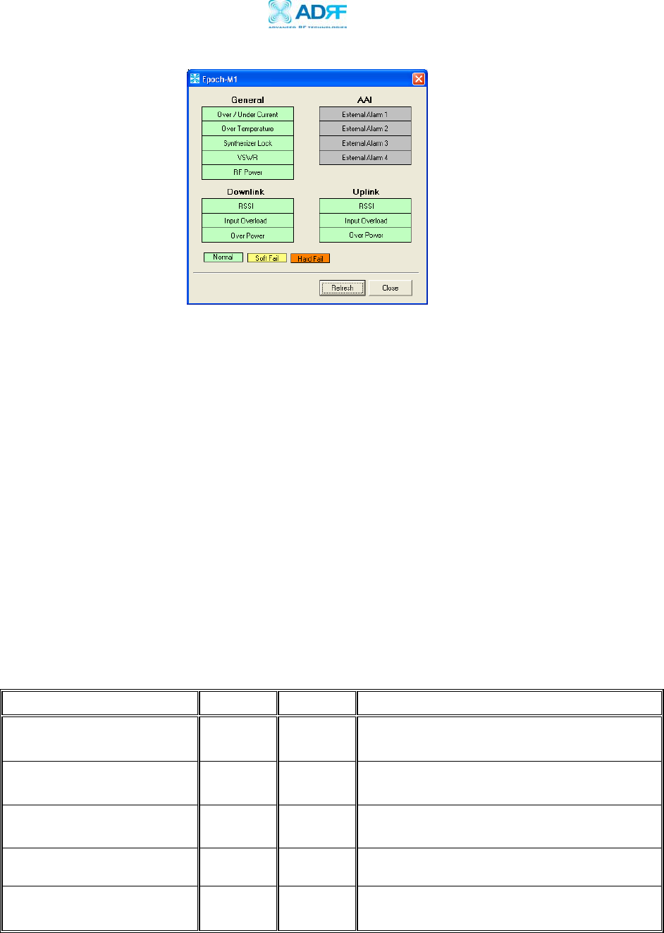
2.3 Alarms
All the various alarms that are supported by Epoch-M1P can be viewed by clicking
the “Alarm” button on the Status Window. If a soft or hard fail alarm should occur,
the corresponding alarm box would be highlighted in yellow or in red respectively.
In order to find out what is causing the alarm(s), simply place the mouse cursor over
the highlighted yellow or red alarm box
(Note: only applicable to some of the alarms)
and a message will appear, displaying the threshold value and the current measured
value. To update the window, click the “Refresh” button.
Advanced RF Technologies, Inc. Proprietary Document Page 25 of 38
Epoch-M1P RF Repeater
User Manual V1.0
Figure 13 - All Alarm Parameters Supported by Epoch-M1P
In the event of a hard fail alarm, the control board will shutdown the HPA (both
uplink & downlink) for 30 seconds and then turns on the HPA to check for a
repeated hard fail occurrence. If the hard fail alarm is persisting up to four
consecutive occurrences, the control board will shutdown the HPA for 20 minutes
(total of five consecutive hard fails). After 20 minutes, the HPA will automatically
come back alive and the control board will check if the Hard Fail alarm has cleared.
If it has not, the same process will continue as mentioned above.
** The alarms can also be viewed on the front panel of the repeater by clicking
the VFD button. Please refer to Appendix B for more detailed information.
rt r r t) f r t
2.3.1
** Epoch-M1P also suppo s AAI (Auxilia y Ala m Inpu . Please re e to Sec ion
1.1.2 on Page 6.
General (Fixed Parameter) Alarms
Alarm List Soft Fail Hard Fail Comments
Over/Under Current O O Soft Fail: Less than 0.5 A @ under current
Hard Fail: More than 4.7 A @ over current
Over Temperature O O Soft Fail: 158 ~ 185 °F
Hard Fail: > 185 °F
Synthesizer Lock - O Band selection will not work properly
VSWR - O > 1.5:1
RF Power - O Will occur in the event of any
Hard Fail alarm
Table 7 - General (Fixed Parameter) Alarms of the Epoch-M1P Software
Advanced RF Technologies, Inc. Proprietary Document Page 26 of 38

Epoch-M1P RF Repeater
User Manual V1.0
2.3.2 Downlink/Uplink Alarms
Alarm List Soft Fail Hard Fail Remark
RSSI O -
Input Power Overload O -
Downlink
(Forward)
Over Power* O O
RSSI O -
Input Power Overload O -
Uplink
(Reverse)
Over Power* O O
Alarms will turn on if the
value is not within operable
limits specified in the
Control Alarm Setting
Window.
Note: The Over Power
parameter is fixed and
cannot be modified by
the user.
Table 8 – List of Alarm Settings of the Epoch-M1P Software
The example below distinguishes the difference between an over power soft
failure and an over power hard failure:
The threshold value for the downlink over power parameter is set to 22.0 dBm
(factory set value), a Hard Fail alarm would occur if the downlink over power
value was greater than 22.0 dBm (20 dBm is the maximum composite power
allowable). Similarly, a Soft Fail alarm would occur if the downlink over power
value was greater than 21.0 dBm but less than 22.0 dBm. Vice versa, the same
example is also applicable in the uplink side.
2.4 Default Control Settings
2.4.1 Default General Settings
Control Item Setting Value
AGC Mode ON
Downlink/Uplink HPA Mode ON
Uplink Tracking Mode ON
Downlink/Uplink Gain 70 dB
Downlink/Uplink AGC Level 20 dBm
Tracking Gain Offset 3 dB
Table 9 - Adjustable Alarm Settings of the Epoch-M1P Epoch-M1P
a. When
Uplink Tracking ON
mode is enabled, the
Tracking Gain Off et
is
set to 3 dB.
s
b. When
AGC ON
mode
is enabled, by default, the
Downlink/Uplink AGC
Level
is set to 20 dBm.
Advanced RF Technologies, Inc. Proprietary Document Page 27 of 38
Epoch-M1P RF Repeater
User Manual V1.0
2.4.2 Default Alarm Setting
Setting Value
Control Item Downlink Uplink
RSSI -95 dBm -110 dBm
Input Overload -35 dBm -35 dBm
Heartbeat On/Off ON
Heartbeat Time 20 minutes
Table 10 - Default Alarm Parameter Values of the Epoch-M1P Software
3 Maintenance Guide for Epoch-M1P
3.1 Periodic Inspection Checklist
a. Check for loose connections to the repeater and antennas. If connections
are loose, make sure that all connections are tightly fastened properly.
b. Cables and connectors are in good condition.
c. Ensure that the repeater brackets are in good condition and that the
repeater is securely fastened.
3.2 Preventive Measures for Optimal Operation
3.2.1
s
3.2.2
Recommendations
• Perform the
Periodic In pection Checklist
quarterly or semiannually.
Precautions
• Do not operate the repeater with the antennas in extremely close
proximity as this may cause damage to the repeater.
• Do not change parameters unless instructed to do so by an authorized
supervisor.
• Do not move the repeater unless instructed to do so by an authorized
supervisor.
• Do not detach any cables to the repeater unless repair of respective
components are necessary.
Advanced RF Technologies, Inc. Proprietary Document Page 28 of 38

Epoch-M1P RF Repeater
User Manual V1.0
4 Troubleshooting
4.1 Tx & Rx LEDs
Tx Rx Explanation
Blinking
GREEN
Blinking
GREEN
Successful Connection. The Epoch-M1P Software and the
repeater are communicating successfully.
Blinking
GREEN
Solid
GREEN
The repeater is not receiving any commands from the
software. In this state, the repeater is either processing or
executing a command. Wait for a few seconds for the Rx LED
to blink periodically.
Blinking
GREEN RED
The repeater is not receiving any commands from the
software. Ensure that the repeater is tuned on and check for
proper USB port connection.
RED RED
The USB port can not send or receive data. Check if the USB
driver has been installed and also verify if the physical
connection on both ends of the USB cable is secure. Ensure
that the repeater is turned on.
Table 11 - Tx and Rx LEDs
** The Tx/Rx LEDs will blink periodically only on the Status Window.
Advanced RF Technologies, Inc. Proprietary Document Page 29 of 38

Epoch-M1P RF Repeater
User Manual V1.0
4.2 Common Installation Problems
Problem Possible Solution
USB port is
not being
recognized
You would need to install the driver for the USB cable which can be
found with the CD that comes with the repeater.
Regardless if you have already installed the USB driver once, if are
connecting the USB cable to a new USB port on the PC for the very first
time, you will need to install the USB driver again.
The power
green LED on
the front panel
is not lit.
Check if the power switch is turned on. Also verify if the power cord is
securely connected to the repeater. Make sure there’s no power
outage.
GUI Software &
Laptop - No
Communication
The very first time during installation, once you connect the USB cable
to the repeater and the laptop, the PC will automatically detect a new
hardware has been added in the system and will prompt you to install
the driver which can be found in the CD. The driver needs to be
installed only once.
Status Window –
Weak Signal or
Donor RSS
Check that the donor and server antennas are connected to the proper
antenna ports on the repeater.
Reposition or rotate the donor antenna around until a stronger signal
is received.
Low Isolation or
Oscillation
Increase the separation between the donor and server antennas by
moving the antennas around or by rotating them.
Downlink/Uplink
VSWR Alarm
Check the cabling because RF signals maybe leaking and also verify
that the connectors are tightly secured.
Downlink/Uplink
Input Power
Overload Alarm
Add an attenuator after the donor/server antenna to reduce the strong
donor/server signal coming into the repeater.
If the repeater is connected to a DAS, there’s a good chance the DAS
system could cause a strong signal to come in on the uplink side of
the repeater, causing an
Uplink Input Power Overload
alarm. If this
happens, add an attenuator on the uplink side of the repeater or
control the signal coming in from the DAS.
Try to reduce the AGC Power Level using the GUI software.
An oscillation in the system could cause this alarm. Check if there is
sufficient separation between the donor and the server antennas.
Downlink/Uplink
Over Power
Alarm
Add an attenuator after the donor/server antenna to reduce the strong
donor/server signal coming into the repeater.
An oscillation in the system could cause this alarm. Check if there is
sufficient separation between the donor and the server antennas.
Table 12 – Troubleshootin
g
Ti
p
s
Advanced RF Technologies, Inc. Proprietary Document Page 30 of 38

Epoch-M1P RF Repeater
User Manual V1.0
5 Warranty and Repair Policy
5.1 General Warranty
The Epoch-M1P carries a Standard Warranty period of two (2) years unless indicated
otherwise on the package or in the acknowledgment of the purchase order.
5.2 Limitations of Warranty
Your exclusive remedy for any defective product is limited to the repair or
replacement of the defective product. Advanced RF Technologies, Inc. may elect
which remedy or combination of remedies to provide in its sole discretion.
Advanced RF Technologies, Inc. shall have a reasonable time after determining that a
defective product exists to repair or replace the problem unit. Advanced RF
Technologies, Inc. warranty applies to repaired or replaced products for the balance
of the applicable period of the original warranty or ninety days from the date of
shipment of a repaired or replaced product, whichever is longer.
5.3 Limitation of Damages
The liability for any defective product shall in no event exceed the purchase price for
the defective product.
5.4 No Consequential Damages
Advanced RF Technologies, Inc. has no liability for general, consequential, incidental
or special damages.
5.5 Additional Limitation on Warranty
Advanced RF Technologies, Inc. standard warranty does not cover products which
have been received improperly packaged, altered, or physically damaged. For
example, broken warranty seal, labels exhibiting tampering, physically abused
enclosure, broken pins on connectors, any modifications made without Advanced RF
Technologies, Inc. authorization, will void all warranty.
Advanced RF Technologies, Inc. Proprietary Document Page 31 of 38

Epoch-M1P RF Repeater
User Manual V1.0
5.6 Return Material Authorization (RMA)
No product may be returned directly to Advanced RF Technologies, Inc. without first
getting an approval from Advanced RF Technologies, Inc. If it is determined that
the product may be defective, you will be given an RMA number and instructions in
how to return the product. An unauthorized return, i.e., one for which an RMA
number has not been issued, will be returned to you at your expense. Authorized
returns are to be shipped to the address on the RMA in an approved shipping
container. You will be given our courier information. It is suggested that the
original box and packaging materials should be kept if an occasion arises where a
defective product needs to be shipped back to Advanced RF Technologies, Inc. To
request an RMA, please call (323) 254-8131 or send an email to
techsupport@adrftech.com.
Advanced RF Technologies, Inc. Proprietary Document Page 32 of 38

Epoch-M1P RF Repeater
User Manual V1.0
Appendix A: Specifications
ELECTRICAL SPECIFICATIONS
PARAMETERS SPECIFICATIONS COMMENTS
DL 1930 to 1990 MHz Frequency
Range UL 1850 to 1910 MHz
Sub Band Filtering One 5 MHz Sliding Block Model 1
Sub Band Filtering One 10 MHz Sliding Block Model 2
Sub Band Filtering One 15 MHz Sliding Block Model 3
Sub Band Filtering Special Custom Band(s) Model 4
Operating Frequency Programmable Freq. Step: 10 KHz
Frequency Error ≤ +/- 0.1 ppm
Delay ≤ 5 usec Each Direction
Input Dynamic Range -35 to -60 dBm
Repeater Gain 55 to 80 dB
Maximum DL&UL Output Power +20 dBm Composite
DL AGC Range 25 dB /0.5 dB Step
UL AGC Range 25 dB /0.5 dB Step
Gain Flatness +/- 2.5 dB
≤ -45 dBc @ Fc +/- 885 KHz
In Band Noise ≤ -50 dBc @ Fc +/- 1.98 MHz
Spurious Emission < -13 dBm @ Fc +/- 2.25 MHz
Rho Factor ≥ 0.912
Noise Figure ≤ 8 dB
VSWR ≤ 1.5:1
Advanced RF Technologies, Inc. Proprietary Document Page 33 of 38

Epoch-M1P RF Repeater
User Manual V1.0
MECHANICAL SPECIFICATIONS
PARAMETERS SPECIFICATIONS COMMENTS
Housing (W x H x D) 8.27 x 11.03 x 3.57 inches
Housing Material Aluminum & Plastic
Weight ≤ 13.22 lbs
Antenna N-Type (Female)
Dry Contact RS-232 (Female)
Connector
Type NMS Control USB / RS-232 (Female)
Cooling External Convection
POWER SPECIFICATIONS
PARAMETERS SPECIFICATIONS COMMENTS
Main AC Power 100 to 240 VAC
AC Frequency 45 to 65 Hz
Power Adapter shall
comply with UL & CE
Adaptor Voltage & Current 6 VDC / 4.5 A
Power Consumption ≤ 30 Watts
ENVIRONMENTAL SPECIFICATIONS
PARAMETERS SPECIFICATIONS COMMENTS
Operating Temperature +41 ˚F to +113 ˚F
Storage Temperature +23 ˚F to +176 ˚F
Humidity 10 to 85%, RH
MTBF 75,000 hours
Advanced RF Technologies, Inc. Proprietary Document Page 34 of 38
Epoch-M1P RF Repeater
User Manual V1.0
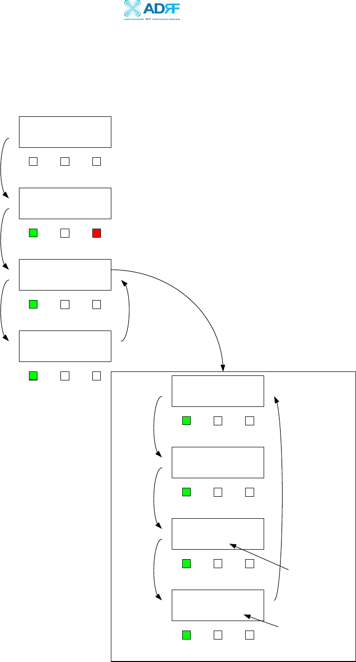
Appendix B: Button Operation
Normal Operation
Power Off
Initializing....
POWER VFD ALARM
Normal Operation
6 sec
16 sec
Booting Time
Power On
(off) (off)
POWER VFD ALARM
(Green) (Red)
If the VFD button
is clicked, the
display will be
come up again.
The VFD display will
be disappeared 30
minutes later since
the VFD button is
touched.
Display Cycle*
POWER VFD ALARM
(Green) (off)
POWER VFD ALARM
(Green) (off) DL: IN GAIN OUT
-102 80.0 -10
If there is no modem
hardware, the display
will be blank. If modem
is there, but not
connected, the display
will be ‘DIS’.
UL: IN GAIN OUT
-102 77.0 -10
Downlink
Uplink
4 sec
BW CH. MODEM
15M 150 CON
4 sec
STATUS
INSTALLED
Band & Channel
Install Status
4 sec
If repeater is not
installed, message
will be
STATUS
NOT INSTALLED
POWER VFD ALARM
(Green) (off)
POWER VFD ALARM
(Green) (off)
POWER VFD ALARM
(Green) (off)
POWER VFD ALARM
(Green) (off)
4 sec
Display Cycle
Advanced RF Technologies, Inc. Proprietary Document Page 35 of 38
Epoch-M1P RF Repeater
User Manual V1.0
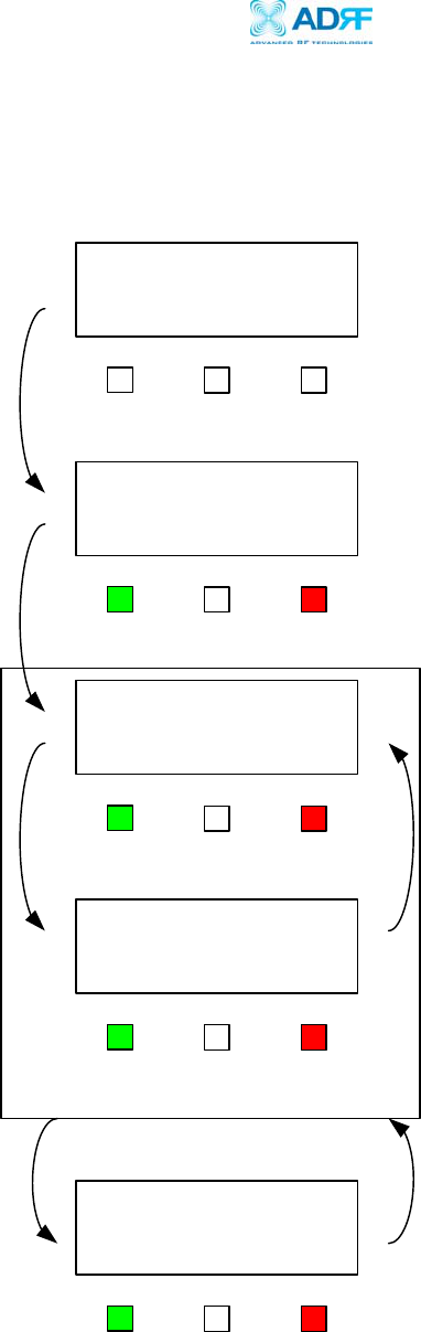
Soft Fail Alarm Operation
Soft Alarm Operation
SOFT FAIL ALARM
DOWNLINK RSSI
Power Off
Initializing....
POWER VFD ALARM
6 sec
16 sec
Booting Time
Power On
(off) (off)
POWER VFD ALARM
(Green) (Red)
If the VFD button
is clicked, the
display will be
come up again.
Display Cycle*
POWER VFD ALARM
(Green) (Red)
POWER VFD ALARM
(Green) (Red)
POWER VFD ALARM
(Green) (Red)
The VFD display will
be disappeared 30
minutes later since
the VFD button is
touched.
4 sec 4 sec
Until the
condition
cleared
Advanced RF Technologies, Inc. Proprietary Document Page 36 of 38
Epoch-M1P RF Repeater
User Manual V1.0
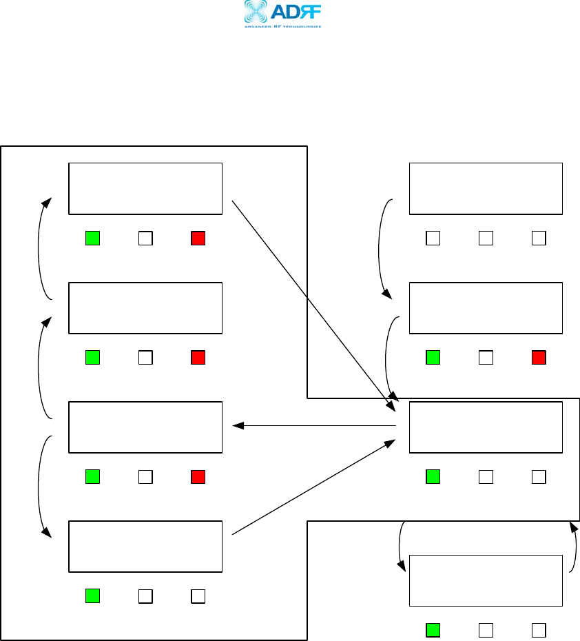
Hard Fail Alarm Operation
Hard Alarm Operation
HARD FAIL ALARM
VSWR
SYSTEM
HALT
HARD FAIL ALARM
CLEARED
20 min
SYSTEM
ALARM CHECKING Power Off
Initializing....
POWER VFD ALARM
6 sec
16 sec
Booting Time
Power On
(off) (off)
POWER VFD ALARM
(Green) (Red)
Display Cycle*
POWER VFD ALARM
(Green) (off)
POWER VFD ALARM
(Green) (Red)
POWER VFD ALARM
(Green) (off)
POWER VFD ALARM
(Green) (Red)
POWER VFD ALARM
(Green) (Red) 4 sec
4 sec
Alarm
Cleared?
Yes
No
If the VFD button
is clicked, the
display will be
come up again.
POWER VFD ALARM
(Green) (off)
The VFD display
will be disappeared
30 minutes later
since the VFD
button is touched.
Right away
Advanced RF Technologies, Inc. Proprietary Document Page 37 of 38
Epoch-M1P RF Repeater
User Manual V1.0
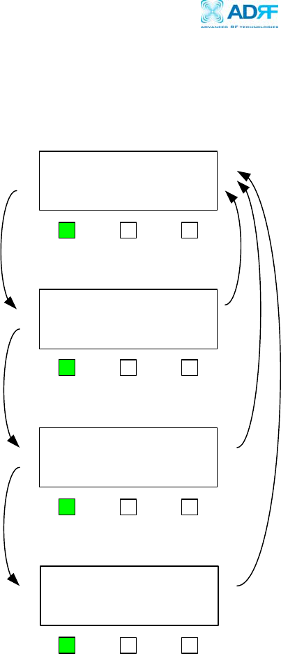
Frequency Change
Frequency Change
CHANNEL
SELECTION MODE
Hold the
VFD
Button
for 5 sec
CHANNEL UP
150 to 175
Push the
ALARM
Button
Push the
ALARM
Button
10 sec
10 sec or
Hold the
VFD Button
for 5 Sec
POWER VFD ALARM
(Green) (off)
POWER VFD ALARM
(off)
CHANNEL UP
175 to 200
10 sec
POWER VFD ALARM
(off)
POWER VFD ALARM
(off)
(Green)
(Green)
(Green)
Advanced RF Technologies, Inc. Proprietary Document Page 38 of 38