Advantech Co ADAM-2017PZ Wireless Sensor Network Data Acquisistion Modules User Manual V4 12 EA User Manual
Advantech Co Ltd Wireless Sensor Network Data Acquisistion Modules V4 12 EA User Manual
UserManual.wiki
>
Advantech Co
>
ADAM 2017PZ User Manual
User manual
Navigation menu
Upload a User Manual
Namespaces
Wiki Guide
HTML
PDF
Info
Views
User Manual
Discussion / Help
Navigation


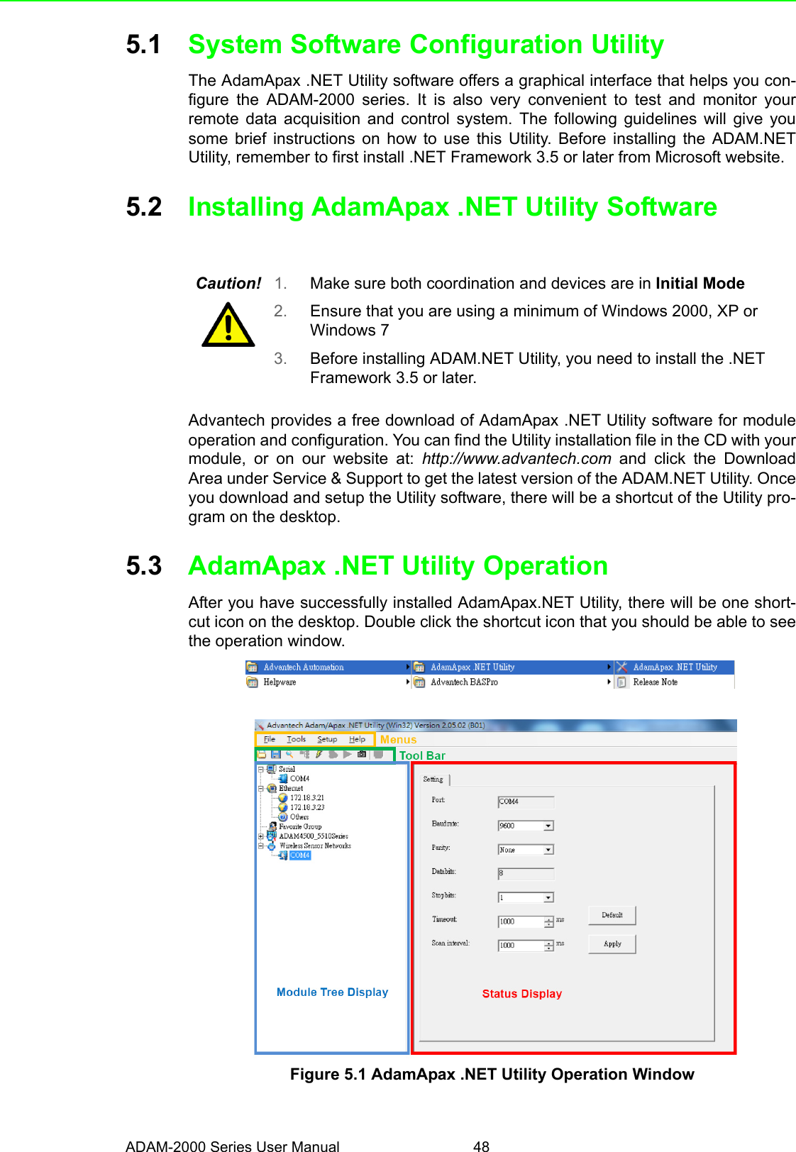
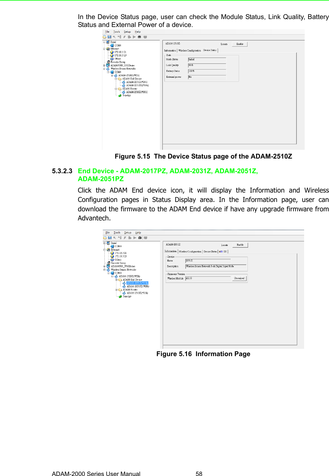
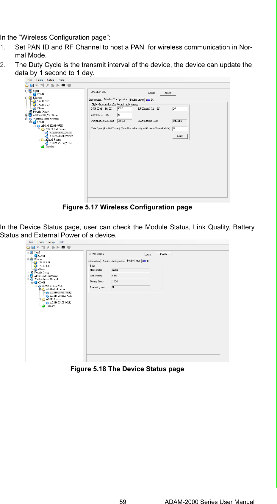
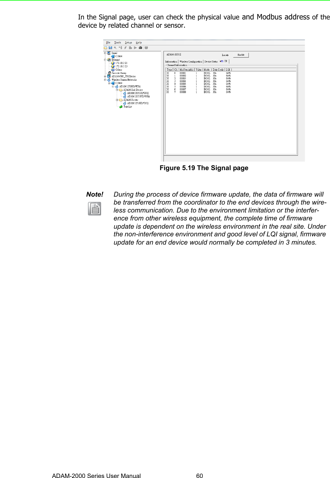
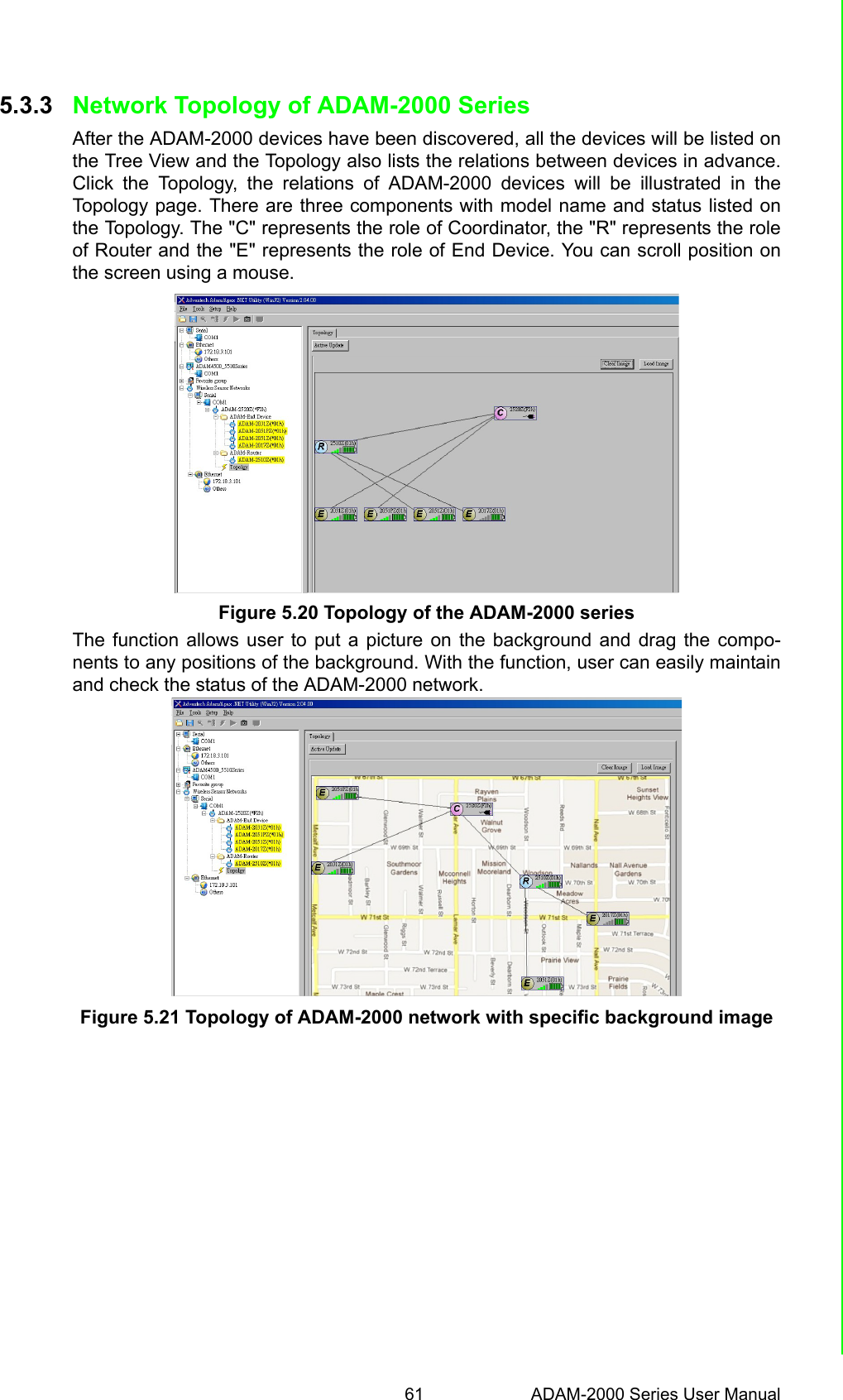
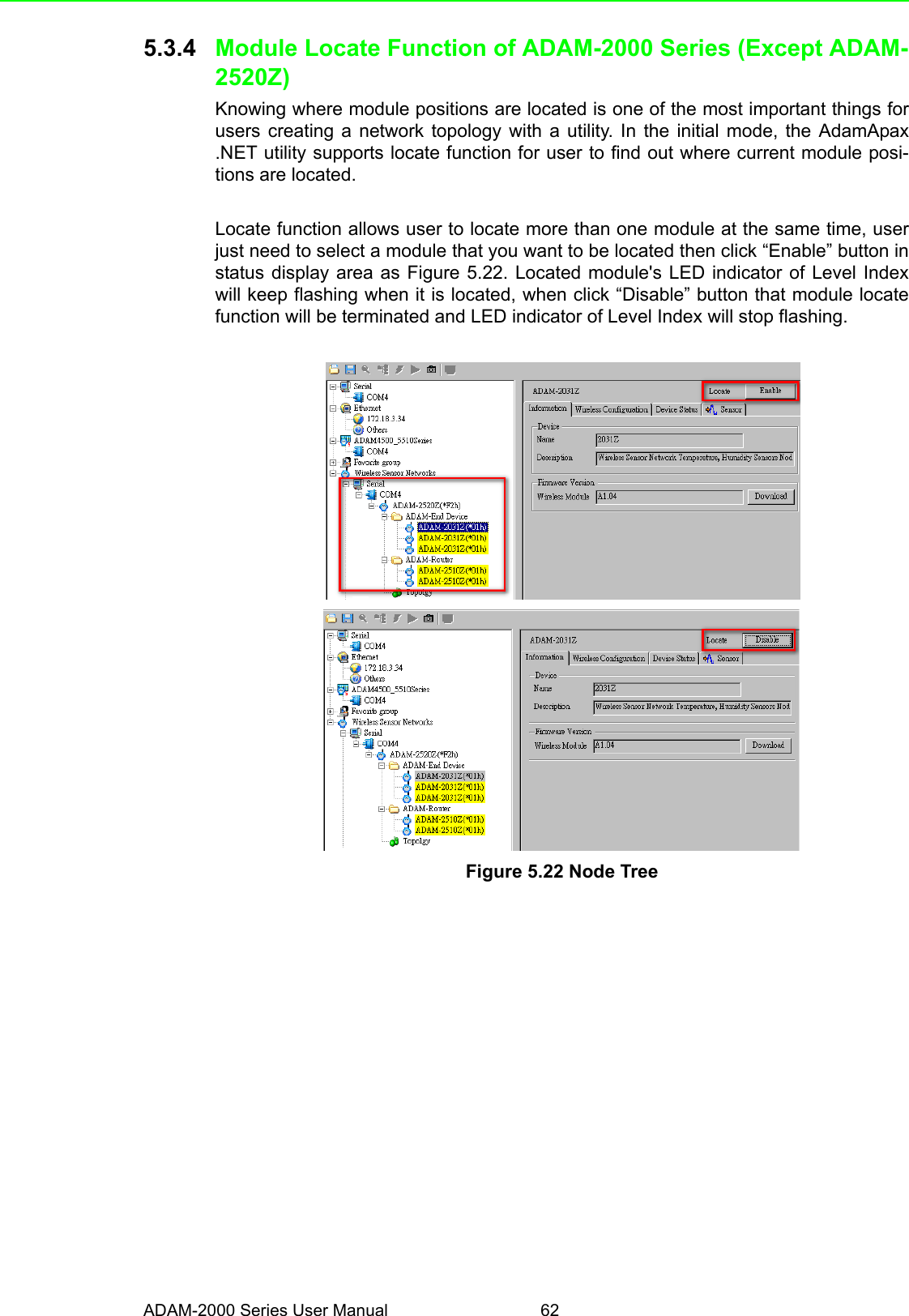
![53 ADAM-2000 Series User ManualChapter 5 Software Configuration GuideThe “Searching the network” dialog will pop up, click “Start” to search the ADAM-2000 devices. The AdamApax .NET Utility search the ADAM-2000 Coordinators fromInitial mode Modbus ID 241(F1h)-244(F4h) [for Normal mode Modbus ID 245(F5h)-249(F5h)], refer to Appendix A.2 for more information.Figure 5.6 Searching the network dialogThe ADAM-2000 coordinators will be listed on the Tree View of the selected COMport.Figure 5.7 Searching the ADAM-2000 coordinators.If you also want to connect ADAM-2000 series to utility at the same time, 1. Make sure they are in initial mode2. Set PAN ID in the same group](https://usermanual.wiki/Advantech-Co/ADAM-2017PZ/User-Guide-2198112-Page-63.png)