Advantech Co ADAM-2017PZ Wireless Sensor Network Data Acquisistion Modules User Manual V4 12 EA User Manual
Advantech Co Ltd Wireless Sensor Network Data Acquisistion Modules V4 12 EA User Manual
User manual

User Manual
ADAM-2000 Series
Wireless Sensor Network Data
Acquisition Modules

ADAM-2000 Series User Manual ii
Copyright
The documentation and the software included with this product are copyrighted 2012
by Advantech Co., Ltd. All rights are reserved. Advantech Co., Ltd. reserves the right
to make improvements in the products described in this manual at any time without
notice. No part of this manual may be reproduced, copied, translated or transmitted
in any form or by any means without the prior written permission of Advantech Co.,
Ltd. Information provided in this manual is intended to be accurate and reliable. How-
ever, Advantech Co., Ltd. assumes no responsibility for its use, nor for any infringe-
ments of the rights of third parties, which may result from its use.
Acknowledgements
Intel and Pentium are trademarks of Intel Corporation.
Microsoft Windows and MS-DOS are registered trademarks of Microsoft Corp.
All other product names or trademarks are properties of their respective owners.
Product Warranty (2 years)
Advantech warrants to you, the original purchaser, that each of its products will be
free from defects in materials and workmanship for two years from the date of pur-
chase.
This warranty does not apply to any products which have been repaired or altered by
persons other than repair personnel authorized by Advantech, or which have been
subject to misuse, abuse, accident or improper installation. Advantech assumes no
liability under the terms of this warranty as a consequence of such events.
Because of Advantech’s high quality-control standards and rigorous testing, most of
our customers never need to use our repair service. If an Advantech product is defec-
tive, it will be repaired or replaced at no charge during the warranty period. For out-
of-warranty repairs, you will be billed according to the cost of replacement materials,
service time and freight. Please consult your dealer for more details.
If you think you have a defective product, follow these steps:
1. Collect all the information about the problem encountered. (For example, CPU
speed, Advantech products used, other hardware and software used, etc.) Note
anything abnormal and list any onscreen messages you get when the problem
occurs.
2. Call your dealer and describe the problem. Please have your manual, product,
and any helpful information readily available.
3. If your product is diagnosed as defective, obtain an RMA (return merchandize
authorization) number from your dealer. This allows us to process your return
more quickly.
4. Carefully pack the defective product, a fully-completed Repair and Replacement
Order Card and a photocopy proof of purchase date (such as your sales receipt)
in a shippable container. A product returned without proof of the purchase date
is not eligible for warranty service.
5. Write the RMA number visibly on the outside of the package and ship it prepaid
to your dealer.
Part No. 2003D01111 Edition 2
Printed in Taiwan May 2013

iii ADAM-2000 Series User Manual
Declaration of Conformity
FCC
This equipment has been tested and found to comply with the limits for a Class B dig-
ital device, pursuant to part 15 of the FCC Rules. These limits are designed to pro-
vide reasonable protection against harmful interference in a residential installation.
This equipment generates, uses and can radiate radio frequency energy and, if not
installed and used in accordance with the instructions, may cause harmful interfer-
ence to radio communications. However, there is no guarantee that interference will
not occur in a particular installation. If this equipment does cause harmful interfer-
ence to radio or television reception, which can be determined by turning the equip-
ment off and on, the user is encouraged to try to correct the interference by one or
more of the following measures:
Reorient or relocate the receiving antenna.
Increase the separation between the equipment and receiver.
Connect the equipment into an outlet on a circuit different from that to which the
receiver is connected.
Consult the dealer or an experienced radio/TV technician for help.
CE
This product has passed the CE test for environmental specifications when shielded
cables are used for external wiring. We recommend the use of shielded cables. This
kind of cable is available from Advantech. Please contact your local supplier for
ordering information.
CE
This product has passed the CE test for environmental specifications. Test conditions
for passing included the equipment being operated within an industrial enclosure. In
order to protect the product from being damaged by ESD (Electrostatic Discharge)
and EMI leakage, we strongly recommend the use of CE-compliant industrial enclo-
sure products.
Technical Support and Assistance
1. Visit the Advantech web site at www.advantech.com/support where you can find
the latest information about the product.
2. Contact your distributor, sales representative, or Advantech's customer service
center for technical support if you need additional assistance. Please have the
following information ready before you call:
–Product name and serial number
–Description of your peripheral attachments
–Description of your software (operating system, version, application software,
etc.)
–A complete description of the problem
–The exact wording of any error messages

ADAM-2000 Series User Manual iv
Warnings, Cautions and Notes
Document Feedback
To assist us in making improvements to this manual, we would welcome comments
and constructive criticism. Please send all such - in writing to: support@advan-
tech.com
Packing List
Before setting up the system, check that the items listed below are included and in
good condition. If any item does not accord with the table, please contact your dealer
immediately.
1x ADAM-2000 Series Device
1x 2dBi Antenna (ADAM-2520Z, ADAM-2510Z, ADAM-2051PZ only)
2 x Mounting Kits
1x CD
Safety Instructions
1. Read these safety instructions carefully.
2. Keep this User Manual for later reference.
3. Disconnect this equipment from any AC outlet before cleaning. Use a damp
cloth. Do not use liquid or spray detergents for cleaning.
4. For plug-in equipment, the power outlet socket must be located near the equip-
ment and must be easily accessible.
5. Keep this equipment away from humidity.
6. Put this equipment on a reliable surface during installation. Dropping it or letting
it fall may cause damage.
7. The openings on the enclosure are for air convection. Protect the equipment
from overheating. DO NOT COVER THE OPENINGS.
8. Make sure the voltage of the power source is correct before connecting the
equipment to the power outlet.
Warning! Warnings indicate conditions, which if not observed, can cause personal
injury!
Caution! Cautions are included to help you avoid damaging hardware or losing
data. e.g.
There is a danger of a new battery exploding if it is incorrectly installed.
Do not attempt to recharge, force open, or heat the battery. Replace the
battery only with the same or equivalent type recommended by the man-
ufacturer. Discard used batteries according to the manufacturer's
instructions.
Note! Advantech reserves the right to change this manual at any time without
notice.

v ADAM-2000 Series User Manual
9. Position the power cord so that people cannot step on it. Do not place anything
over the power cord.
10. All cautions and warnings on the equipment should be noted.
11. If the equipment is not used for a long time, disconnect it from the power source
to avoid damage by transient overvoltage.
12. Never pour any liquid into an opening. This may cause fire or electrical shock.
13. Never open the equipment. For safety reasons, the equipment should be
opened only by qualified service personnel.
14. If one of the following situations arises, get the equipment checked by service
personnel:
15. The power cord or plug is damaged.
16. Liquid has penetrated into the equipment.
17. The equipment has been exposed to moisture.
18. The equipment does not work well, or you cannot get it to work according to the
user's manual.
19. The equipment has been dropped and damaged.
20. The equipment has obvious signs of breakage.
21. DO NOT LEAVE THIS EQUIPMENT IN AN ENVIRONMENT WHERE THE
STORAGE TEMPERATURE MAY GO BELOW -40°C (-40°F) OR ABOVE 85°C
(185°F). THIS COULD DAMAGE THE EQUIPMENT. THE EQUIPMENT
SHOULD BE IN A CONTROLLED ENVIRONMENT.
22. CAUTION: DANGER OF EXPLOSION IF BATTERY IS INCORRECTLY
REPLACED. REPLACE ONLY WITH THE SAME OR EQUIVALENT TYPE
RECOMMENDED BY THE MANUFACTURER, DISCARD USED BATTERIES
ACCORDING TO THE MANUFACTURER'S INSTRUCTIONS.
23. The sound pressure level at the operator's position according to IEC 704-1:1982
is no more than 70 dB (A).
DISCLAIMER: This set of instructions is given according to IEC 704-1. Advantech
disclaims all responsibility for the accuracy of any statements contained herein.
Safety Precaution - Static Electricity
Follow these simple precautions to protect yourself from harm and the products from
damage.
Disconnect power before making any configuration changes. The sudden rush of
power as you connect a jumper or install a card may damage sensitive electronic
components.

ADAM-2000 Series User Manual vi

vii ADAM-2000 Series User Manual
Contents
Chapter 1 Understanding Your System ..............1
1.1 Introduction ............................................................................................... 2
Figure 1.1 ADAM-2000 Series System Architecture.................... 2
Figure 1.2 ADAM-2000 Series Operating Distance ..................... 2
1.1.1 IEEE 802.15.4 Wireless Standard ................................................ 3
Table 1.1: Wireless Specifications............................................... 3
1.1.2 Wireless Sensor Network.............................................................. 3
1.1.3 Low-power Consumption and Battery-Powered Design ............... 4
1.1.4 Sensor Embedded Design ............................................................ 4
1.1.5 Wireless Signal Indicator .............................................................. 4
1.1.6 Industrial Standard Modbus Protocol............................................ 4
1.1.7 SCADA Software Support............................................................. 4
1.1.8 Advantech Software Alignment..................................................... 4
1.2 Specifications ............................................................................................ 5
1.2.1 ADAM-2000 Series Hardware Specification ................................. 5
1.2.2 LED Status.................................................................................... 6
Figure 1.3 LED Indicators ............................................................ 6
Table 1.2: LED Indicator Definitions ............................................ 6
1.2.3 Wireless Communication Range................................................... 7
1.2.4 Selecting Topology ..................................................................... 10
Table 1.3: Topology Comparison Table .................................... 10
1.3 Dimensions ............................................................................................. 11
Figure 1.4 ADAM-2000 Series Dimensions ............................... 11
1.4 Mounting ................................................................................................. 12
1.4.1 Panel Mounting ........................................................................... 12
Figure 1.5 Panel Mounting Dimensions..................................... 12
1.4.2 DIN-rail Mounting ........................................................................ 13
Figure 1.6 Fixing ADAM-2000 to DIN rail adaptor ..................... 13
Figure 1.7 Fixed ADAM-2000 to DIN rail ................................... 13
1.5 Wiring & Connections.............................................................................. 14
1.5.1 Power Supply Wiring................................................................... 14
Figure 1.8 Power Wiring Diagram.............................................. 14
1.5.2 I/O Module Wiring ....................................................................... 15
1.5.3 Communication Wiring................................................................ 15
Figure 1.9 RS-422/485 and USB interface of ADAM-2520Z. .... 15
Figure 1.10Wiring Diagram for ADAM-2520Z............................. 16
Chapter 2 Selecting Your Hardware ..................17
2.1 Selecting an ADAM-2000 Module ........................................................... 18
2.1.1 Selecting a Communication Module ........................................... 18
Table 2.1: Communication Module Selection Guidelines .......... 18
2.1.2 Selecting an I/O .......................................................................... 19
Table 2.2: I/O Selection Guidelines ........................................... 19
2.1.3 Selecting a Sensor Module ......................................................... 19
Table 2.3: Sensor Mode Selection ............................................ 19
2.2 Selecting an Operator Interface .............................................................. 20
Chapter 3 Module Introduction ..........................21
3.1 Communication Modules......................................................................... 22
3.1.1 ADAM-2510Z .............................................................................. 22
3.1.2 ADAM-2520Z .............................................................................. 23

ADAM-2000 Series User Manual viii
3.2 I/O and Sensor Modules ......................................................................... 24
3.2.1 ADAM-2017PZ............................................................................ 24
Figure 3.1 Current Input Wiring Diagram of ADAM-2017PZ ..... 26
Figure 3.2 Voltage Input Wiring Diagram of ADAM-2017PZ ..... 26
3.2.2 ADAM-2031Z .............................................................................. 27
3.2.3 ADAM-2051Z .............................................................................. 29
3.2.4 ADAM-2051PZ............................................................................ 30
Figure 3.3 ADAM-2051Z/2051PZ Wet Contact Diagram........... 31
Figure 3.4 ADAM-2051Z/2051PZ Dry Contact Diagram ........... 31
Chapter 4 Installation Guide.............................. 33
4.1 Determining the Proper Environment...................................................... 34
4.1.1 Package Contents ...................................................................... 34
4.1.2 System Requirements ................................................................ 34
4.1.3 Perform a Wireless Sensor Network........................................... 34
Figure 4.1 The Architecture of the Wireless Sensor Network.... 35
4.2 Establish the Connection ........................................................................ 36
4.2.1 Basic Installation......................................................................... 36
Figure 4.2 Multi-End Device Network performance................... 38
Figure 4.3 Multi-End Device and Router Network Relationship 39
4.2.2 ADAM-2000 Series Installation Flowcharts ................................ 39
Figure 4.4 ADAM-2000 Installation Chart.................................. 40
4.3 Advanced Functions ............................................................................... 44
4.3.1 Link Quality Indicator .................................................................. 44
Table 4.1: Level of LQI .............................................................. 44
4.3.2 Battery Level............................................................................... 44
Table 4.2: Level of battery power .............................................. 44
4.3.3 Pairing......................................................................................... 45
4.3.4 Associating Devices.................................................................... 45
4.3.5 Reboot ........................................................................................ 45
4.3.6 Button Function Table................................................................. 45
Table 4.3: Button Functions ...................................................... 45
4.4 Conduct a Site Survey ............................................................................ 46
4.4.1 Before Going Onsite ................................................................... 46
4.4.2 Onsite Survey ............................................................................. 46
Chapter 5 Software Configuration Guide ......... 47
5.1 System Software Configuration Utility..................................................... 48
5.2 Installing AdamApax .NET Utility Software ............................................. 48
5.3 AdamApax .NET Utility Operation .......................................................... 48
Figure 5.1 AdamApax .NET Utility Operation Window .............. 48
Figure 5.2 AdamApax .NET Utility Toolbar................................ 50
5.3.1 USB Driver Installation................................................................ 51
5.3.2 Search and Configure the ADAM-2000 Series ........................... 51
Figure 5.3 ADAM-2000 Series AdamApax .NET Utility Support 51
Figure 5.4 Search the USB interface ADAM-2000 devices on the
host PC for the virtual COM port. ............................. 52
Figure 5.5 Search the COM port for the ADAM-2000 devices. . 52
Figure 5.6 Searching the network dialog ................................... 53
Figure 5.7 Searching the ADAM-2000 coordinators.................. 53
Figure 5.8 ADAM-2000 devices lists on the Tree View and Infor-
mation page.............................................................. 54
Figure 5.9 The overview of ADAM-2000 end devices. .............. 55
Figure 5.10The overview of ADAM-2000 routers ....................... 55
Figure 5.11Information page of ADAM-2520Z............................ 56
Figure 5.12Wireless Configuration page of the ADAM-2520Z. .. 56
Figure 5.13 Information page of ADAM-2510Z........................... 57

ix ADAM-2000 Series User Manual
Figure 5.14Wireless Configuration page of ADAM-2510Z.......... 57
Figure 5.15 The Device Status page of the ADAM-2510Z ......... 58
Figure 5.16 Information Page ..................................................... 58
Figure 5.17Wireless Configuration page .................................... 59
Figure 5.18The Device Status page ........................................... 59
Figure 5.19The Signal page ....................................................... 60
5.3.3 Network Topology of ADAM-2000 Series ................................... 61
Figure 5.20Topology of the ADAM-2000 series.......................... 61
Figure 5.21Topology of ADAM-2000 network with specific back-
ground image............................................................ 61
5.3.4 Module Locate Function of ADAM-2000 Series (Except ADAM-
2520Z)......................................................................................... 62
Figure 5.22Node Tree................................................................. 62
5.3.5 Group Configuration.................................................................... 63
Figure 5.23Group Configuration ................................................. 63
Figure 5.24Firmware Update in Group Configuration................. 63
Figure 5.25Wireless Setting of Group Configuration .................. 64
Chapter A ADAM-2000 Series Functions...........65
A.1 Introduction ............................................................................................. 66
A.2 ADAM-2000 I/O Modbus Mapping Table ................................................ 66
Table A.1: Modbus ID Table of ADAM-2000 series ................... 66
A.2.1 ADAM-2520Z .............................................................................. 67
Table A.2: ADAM-2520Z Mapping Table ................................... 67
A.2.2 ADAM-2510Z .............................................................................. 68
Table A.3: ADAM-2510Z Mapping Table ................................... 68
A.2.3 ADAM-2017PZ............................................................................ 69
Table A.4: ADAM-2017PZ Mapping Table................................. 69
A.2.4 ADAM-2031Z .............................................................................. 72
Table A.5: ADAM-2031Z Mapping Table ................................... 72
A.2.5 ADAM-2051Z .............................................................................. 74
Table A.6: ADAM-2051Z Mapping Table ................................... 74
A.2.6 ADAM-2051PZ............................................................................ 75
Table A.7: ADAM-2051PZ Mapping Table................................. 75
Chapter B Troubleshooting ................................77
B.1 Troubleshooting ...................................................................................... 78
B.2 Notice ...................................................................................................... 79

ADAM-2000 Series User Manual x

Chapter 1
1Understanding Your
System
ADAM-2000 Series User Manual 2
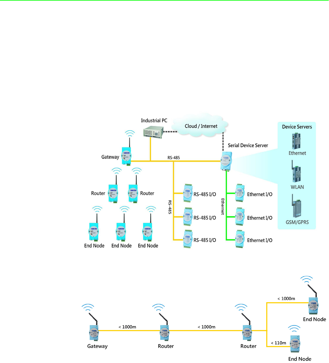
1.1 Introduction
ADAM-2000 series is the wireless solution of the ADAM families and integrates the
IEEE 802.15.4 standard, I/O and Sensor technologies known as Wireless Sensor
Network. Different from the wired solution, the flexible network capability makes it
easy to extend or construct a cost-effective distributed monitoring system for variety
of applications. Through popular industrial Modbus protocol, the ADAM-2000 can be
integrated into any HMI and SCADA system. The low-power consumption design
also makes it possible for standalone applications with batteries. The sensor embed-
ded design provides compact size for specified application. With the ADAM-4000 and
ADAM-6000, the ADAM provides the total solutions of remote I/O. Please refer to
Figure 1-1 for a brief overview of the ADAM-2000 system architecture..
Figure 1.1 ADAM-2000 Series System Architecture
Figure 1.2 ADAM-2000 Series Operating Distance

3 ADAM-2000 Series User Manual
Chapter 1 Understanding Your System
1.1.1 IEEE 802.15.4 Wireless Standard
IEEE 802.15.4 is a wireless standard defined as Low Rate Wireless Personal Area
Network (LR-WPAN) or usually called Wireless Personal Area Network (WPAN)
instead. It is designed for low-power consumption and robust wireless communica-
tion, especially for small data packet applications, such as sensor, I/O and etc. IEEE
802.15.4 is a low data rate, low power consumption, low cost, wireless networking
protocol targeted towards automation and remote control applications. It is expected
to provide low cost and low power connectivity for equipment that needs battery life
as long as several months to several years but does not require data transfer rates
as high as those enabled by Bluetooth. The IEEE 802.15.4 standard only defines the
PHY and MAC layers. The working RF are 918MHz for EU, 868MHz for USA and
2.4GHz for World Wide.
1.1.2 Wireless Sensor Network
The Wireless Sensor Network is based on the IEEE 802.15.4 standard and inherits
all the characteristics. Coordinator, Router and End Device (or called End Node) are
the basic components to perform the PAN.
A coordinator is the data collection center in a PAN and also plays as a gateway to
transfer and translate wireless data to other interfaces, such as RS-232, RS-485,
Ethernet and so on.
A router is a wireless repeater to enhance the wireless signal and a wireless router to
select optimized path for wireless communication between coordinator and end
nodes.
An end node is a wireless remote I/O for data acquisition. The data acquires from
sensors or devices can be transmitted through it. The end node can communicate
with coordinator directly or via a router to coordinator.
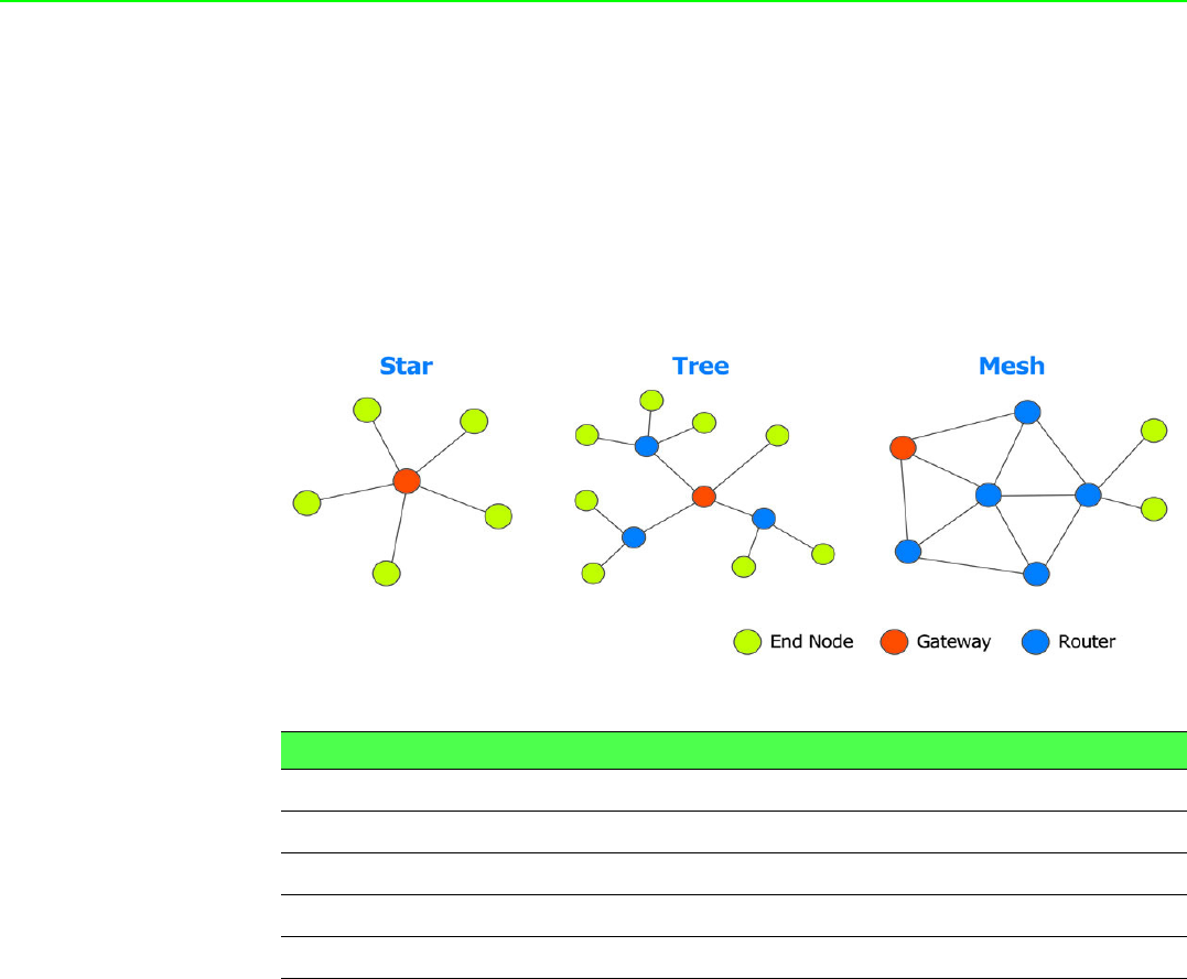
As traditional network, the Wireless Sensor Network provides the star, tree and mesh
topologies for various applications.
Table 1.1: Wireless Specifications
Feature(s) IEEE 802.11b Bluetooth IEEE 802.15.4
Data Rate 11Mbps 1Mbps 250Kbps
Power Consumption Hours (High) Days Years (Low)
Connection Very Complex Complex Simple
Connection Speed Up to 3 seconds Up to 10 seconds 30ms
Extendibility Roaming possible No Yes
Reliability Low High High

ADAM-2000 Series User Manual 4
1.1.3 Low-power Consumption and Battery-Powered Design
ADAM-2000 is designed as a standalone device for applications that require long-
time operation without maintenance. Therefore power consumption taken into con-
sideration during its design. The ADAM-2000 not only follows the IEEE 802.15.4
standard for low-power consumption wireless communication, but also optimizes the
peripheral HW and FW design to achieve the uA-level power consumption: making it
capable of being powered using 2 AA batteries.
1.1.4 Sensor Embedded Design
Sensor embedded design makes the ADAM-2000 even better in some specified and
compact applications. The ADAM-2031Z integrates a temperature and a humidity
sensor. The module is suitable for building automation, Green-house, environment
applications which require the specified sensors. With the batteries installed into the
ADAM-2031Z no extra wiring is required to power the module.
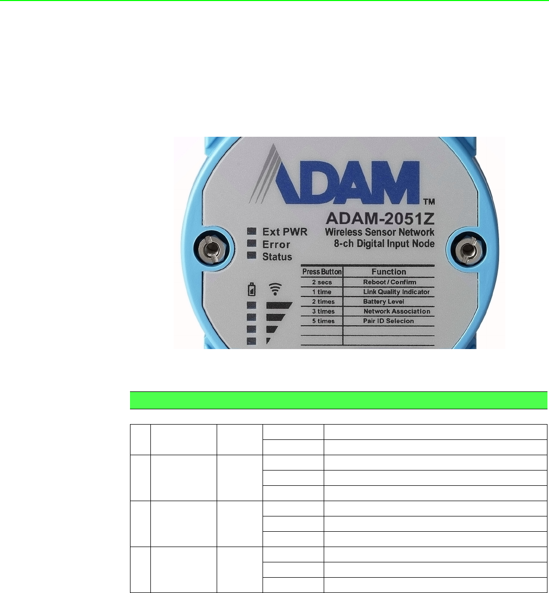
1.1.5 Wireless Signal Indicator
There are LEDs in the front of the panel to display the status of device. The LEDs can
indicate the device's status, wireless signal strength, battery power level and error
conditions. With the LEDs, users can easily check the status of the ADAM-2000 by
pressing a button on the side of the ADAM-2000.
1.1.6 Industrial Standard Modbus Protocol
Modbus is an industrial standard serial communication protocol, and a commonly
available way of connecting industrial electronic devices. Modbus allows for commu-
nication between many devices connected to the same network. Modbus RTU is
used in serial communication and makes use of a compact binary representation of
the data for protocol communication. The RTU format follows the commands/data
with a cyclic redundancy check checksum as an error check mechanism to ensure
the reliability of data.
1.1.7 SCADA Software Support
ADAM-2000 supports industrial standard Modbus protocol and can be integrated into
Advantech HMI- WOP, SCADA - WebAccess and 3rd party HMI. With the different
ADAM-2000 modules, it is able to acquire signal from digital input, analog input, tem-
perature, humidity and concentration then the signals can be apply to your applica-
tion.
1.1.8 Advantech Software Alignment
As with all other ADAM devices, the ADAM-2000 series is integrated into the AdamA-
pax .NET Utility, therefore users will have an identical user experience. With the pow-
erful Advantech software, only a few steps are required to search and configure the
ADAM-2000 series.
Note! 1. When Device adopts batteries for main power source, long network
disconnection or association fail which will cause device into net-
work reassociation mechanism then sharply reduce battery life.
2. For the choice of battery, we suggest Energizer L91 Ultimate Lith-
ium AA battery.

5 ADAM-2000 Series User Manual
Chapter 1 Understanding Your System
1.2 Specifications
1.2.1 ADAM-2000 Series Hardware Specification
IEEE Standards: IEEE 802.15.4
Modulation Type: OQPSK
Frequency Band: 2.4GHz ~ 2.4835GHz
Channels: 11 - 26
RF Data Rate: 250 kbps
Transmit Power: 3dBm (1.6mW), 15dBm(20mW) & 19dBm(79mW)
Receiver Sensitivity: -97 dBm
Transmission Power:
–ADAM-2031Z, ADAM-2051Z: 3 ± 1dBm
–ADAM-2017PZ: 16 dBm(max peak power)
–ADAM-2051PZ, ADAM-2510Z, ADAM-2520Z: 19 ± 1dBm
Outdoor Range (Line of Sight *):
–ADAM-2031Z, ADAM-2051Z: 110m
–ADAM-2017PZ, ADAM-2051PZ, ADAM-2510Z, ADAM-2520Z: 1000m
Topology: Star/Tree/Mesh
Range Extenders: Maximum 5 Hops
Operating Temperature Range: -20°C ~ 70°C (-4°F ~ 157.9°F)
Operating Temperature Range (Battery Powered): 0oC ~ 50oC (32oF~122oF)
Storage Temperature: -40oC ~ 85oC (-40oF~185oF)
Operation Humidity: 20% ~ 95%
Storage Humidity: 0% ~ 95%
Note! * Outdoor Range is estimated with line of sight. The real transmitting dis-
tance would be affected by the environment of application site. Please
perform site survey to determine the set up range of wireless network.
ADAM-2000 Series User Manual 6
1.2.2 LED Status
There are four types of LED status on the front panel of ADAM-2000 series.
1. Ext PWR: Green LED
2. Error: Red LED
3. Status: Yellow LED
4. Level Index:4x Amber LEDs
Figure 1.3 LED Indicators
Table 1.2: LED Indicator Definitions
Name Color LED Status Definition
1Ext PWR Green On External/USB Power Input
Off No External/USB Power Input
2Error Red
Blinking Network Connecting
On Error, refer to Appendix B for more information
Off No error
3 Status Yellow
On Initial Mode
Off Normal Mode
Blinking Configure Pairing ID (Initial Mode)
4 Level Index Amber
On Pair ID
Off No LQI / Battery Level
Blinking LQI Level and Battery Level
7 ADAM-2000 Series User Manual
Chapter 1 Understanding Your System
1.2.3 Wireless Communication Range
Thought the wireless technology brings the advantage of flexibility, cost-effective wir-
ing and easy deployment, but users must understand its limitations to enjoy the ben-
efits of the wireless technology.
The Link Quality Indicator (LQI) of the ADAM-2000 displays how the facts below
affect the wireless signal. Its indicator represents the Received Signal Strength Indi-
cation (RSSI) and the retransmission times of a packet. The better the LQI, the better
the wireless data packet transmission quality. The limitation of the wireless communi-
cation range depends on following factors:
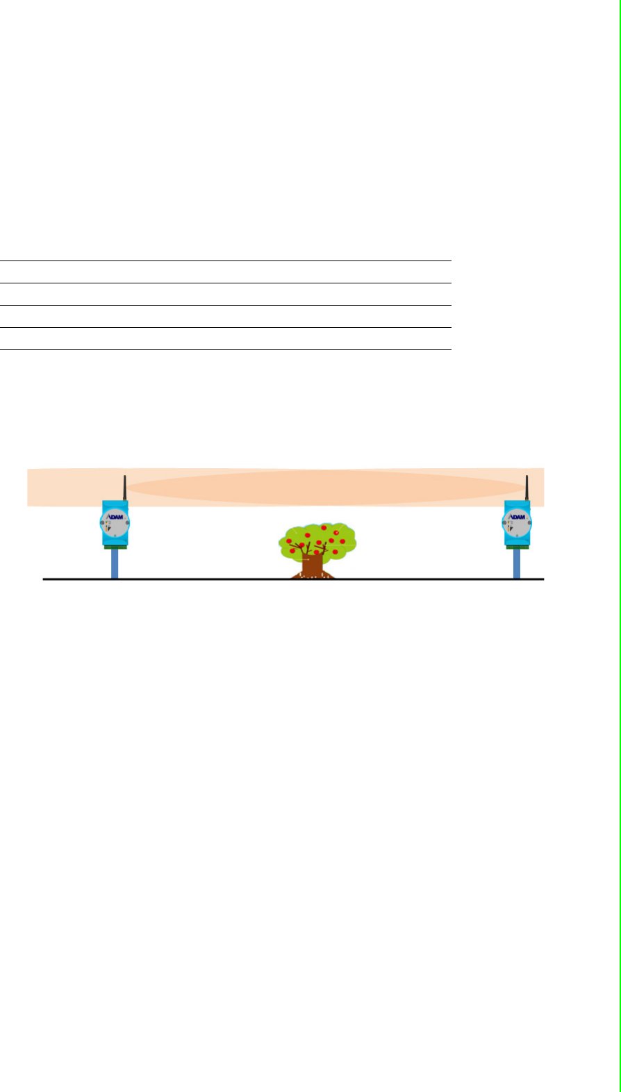
1.2.3.1 Line of Sight
The distance of each node is defined as the clear path between the antennas which
known as line of sight. Anything within the path will interrupt the radio transmission
that interference the communication. Beware of the trees, buildings, moving objects,
or other obstacles in between the antennas.
Transmission power Receiver sensitivity
Interference Line of Sight
Antenna Performance Shelter
Altitude above Ground Free Space Loss
ADAM-2000 Series User Manual 8
1.2.3.2 Multi-path and Reflection of Signal
When the modules used in indoor place, beware of the signal reflection. The reflec-
tion can help the signal cross the obstacle. It can also generate the multi-paths which
will also cause signal attenuation. This is the reason why the transmission distance
may be reduced in indoor place.
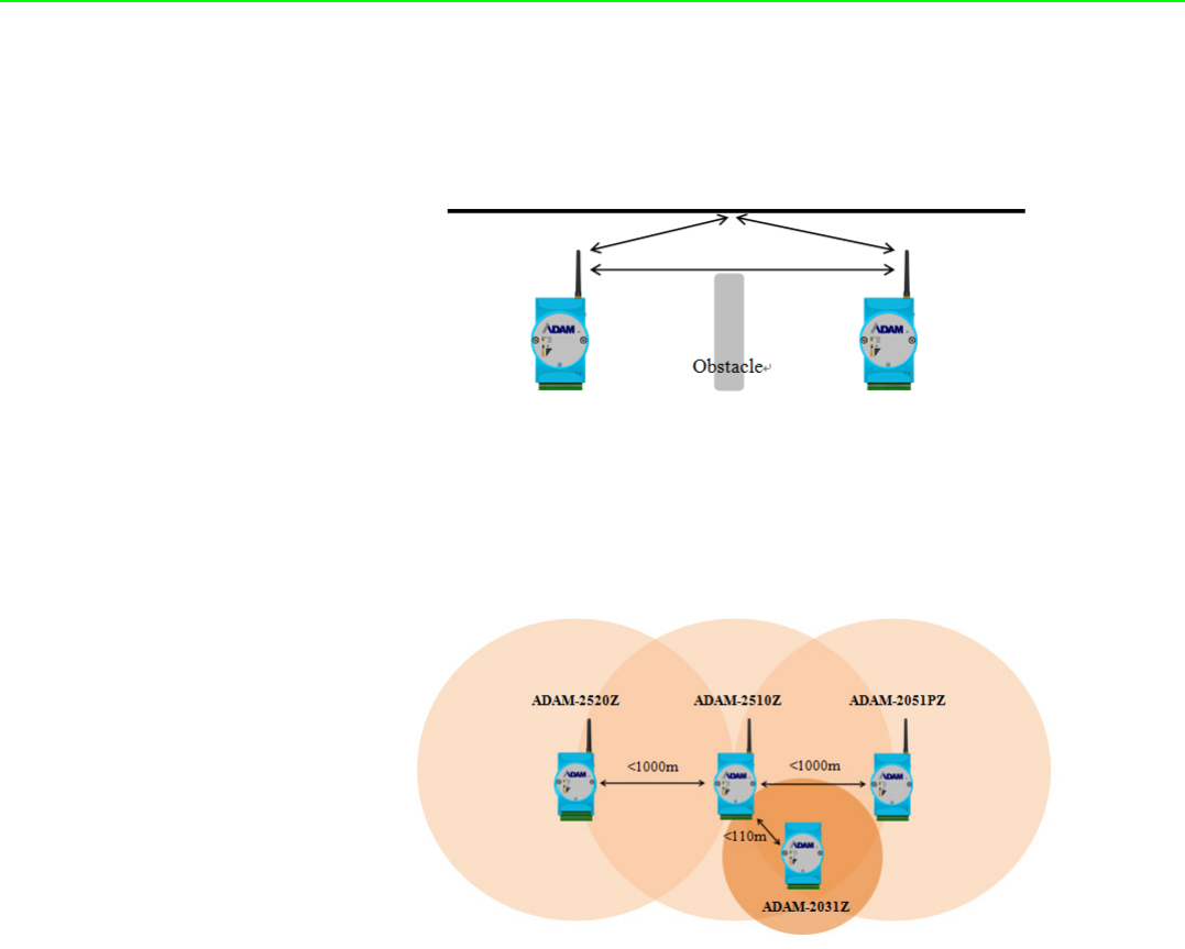
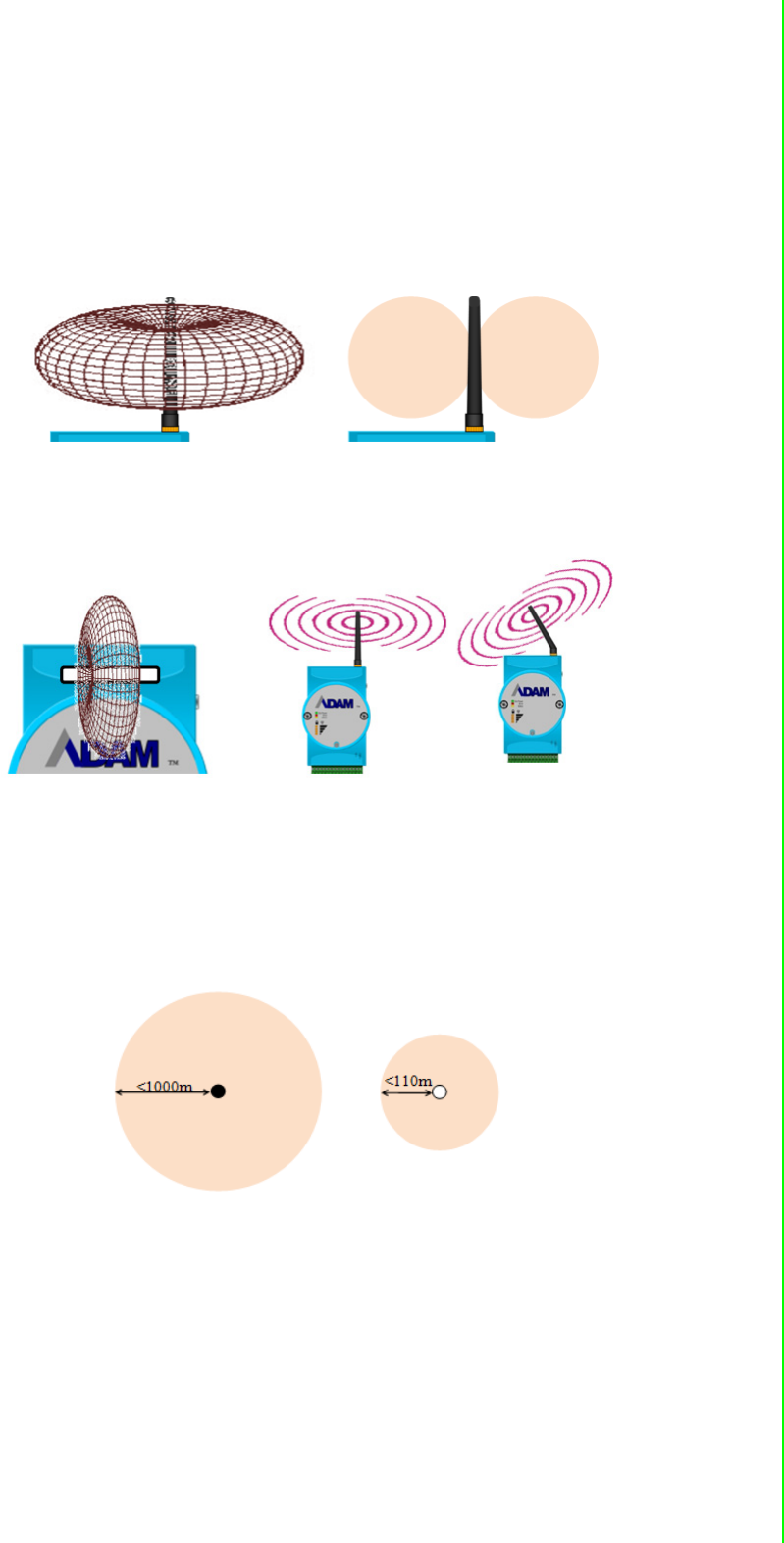
1.2.3.3 Distance between Different Types of Modules
Following figure demonstrate the transmission distance between each type of mod-
ules. The distance between the modules with power amplifier can be around 1000m
under clear line of sight. But if the module without power amplifier is used here, the
distance will be restricted by the power of the antenna of the module. So the path will
be around 110m.
9 ADAM-2000 Series User Manual
Chapter 1 Understanding Your System
1.2.3.4 ADAM-2000 Antenna Pattern
The antenna of the modules with power amplifier uses the Omni-directional antenna.
Its antenna pattern looks like a doughnut as the figure on the left below. The cross-
sectional view of the antenna pattern is on the right below. The plane vertical to
antenna has stronger signal, but the region on or under the antenna has lower signal.
The modules including: ADAM-2520Z, ADAM-2510Z, ADAM-2017PZ, and ADAM-
2051PZ.
The modules without power amplifier use a build-in antenna inside the module. The
build-in antenna is shown as a white bar on the left figure below. Its antenna pattern
is also looks like a doughnut which vertical to antenna. The modules including:
ADAM-2031Z and ADAM-2051Z.
For improving better performance of signal, user may need to adjust the angle of the
antenna to change the antenna pattern. Beware of the relationship of the angle
between position of router and end-devices.
The transmission distance of the modules is defined under the condition of clear line
of sight. Following are the top view of antenna. The modules with power amplifier has
less than 1000 m distance as the figure on the left, and the modules without power
amplifier are less than 110 m.
ADAM-2000 Series User Manual 10
1.2.4 Selecting Topology
Usually, when building a network solution, the user has to take into consideration the
topology that will be used since different topologies have different characteristics.
The ADAM-2000 series provides start, tree and mesh topologies. No further configu-
ration is required, the ADAM-2000 series will automatically associate the network by
the locations of the ADAM-2000 series units. Users may select the correct topology
and install ADAM-2000s for their application systems. The topology is depend on the
number and the position of routers.See the image below and Table 1.3 provide the
illustrations and characteristics comparison table of the three topologies.
Table 1.3: Topology Comparison Table
Topology Star Tree Mesh
Power Consumption Low Medium High
Installation Fee Low Medium High
Network Coverage Small Large Large
Network Capability Small Large Large
11 ADAM-2000 Series User Manual
Chapter 1 Understanding Your System
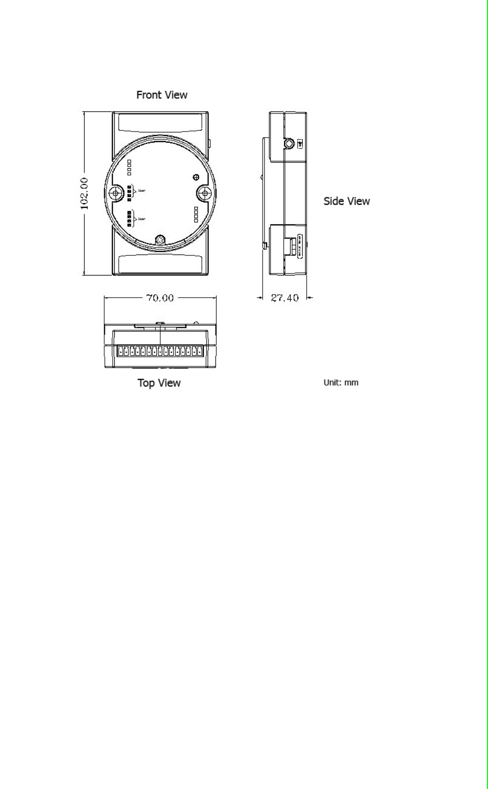
1.3 Dimensions
Figure 1.4 ADAM-2000 Series Dimensions
ADAM-2000 Series User Manual 12
1.4 Mounting
ADAM-2000 series modules are designed as compact units and are allowed to be
installed in the field site with the following methods.
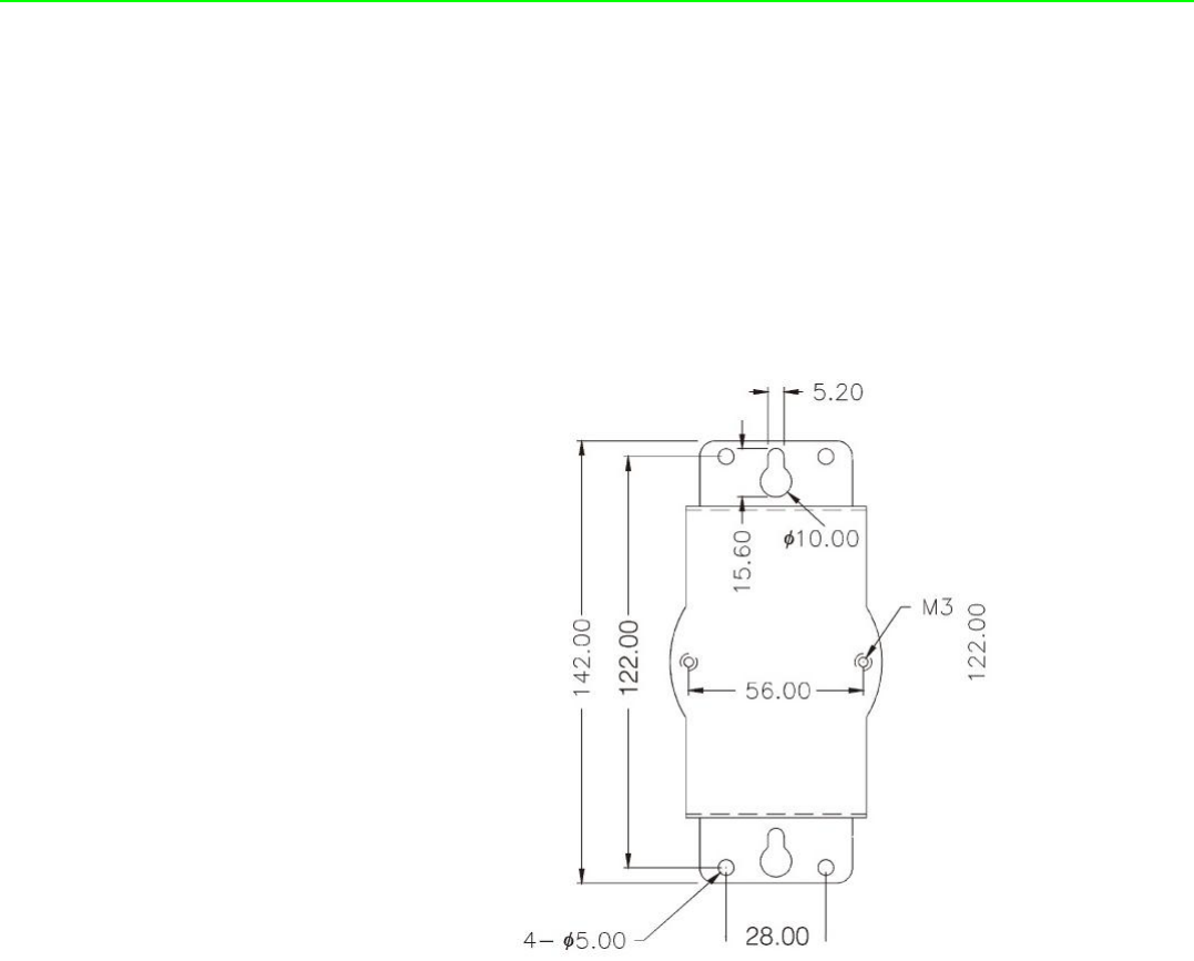
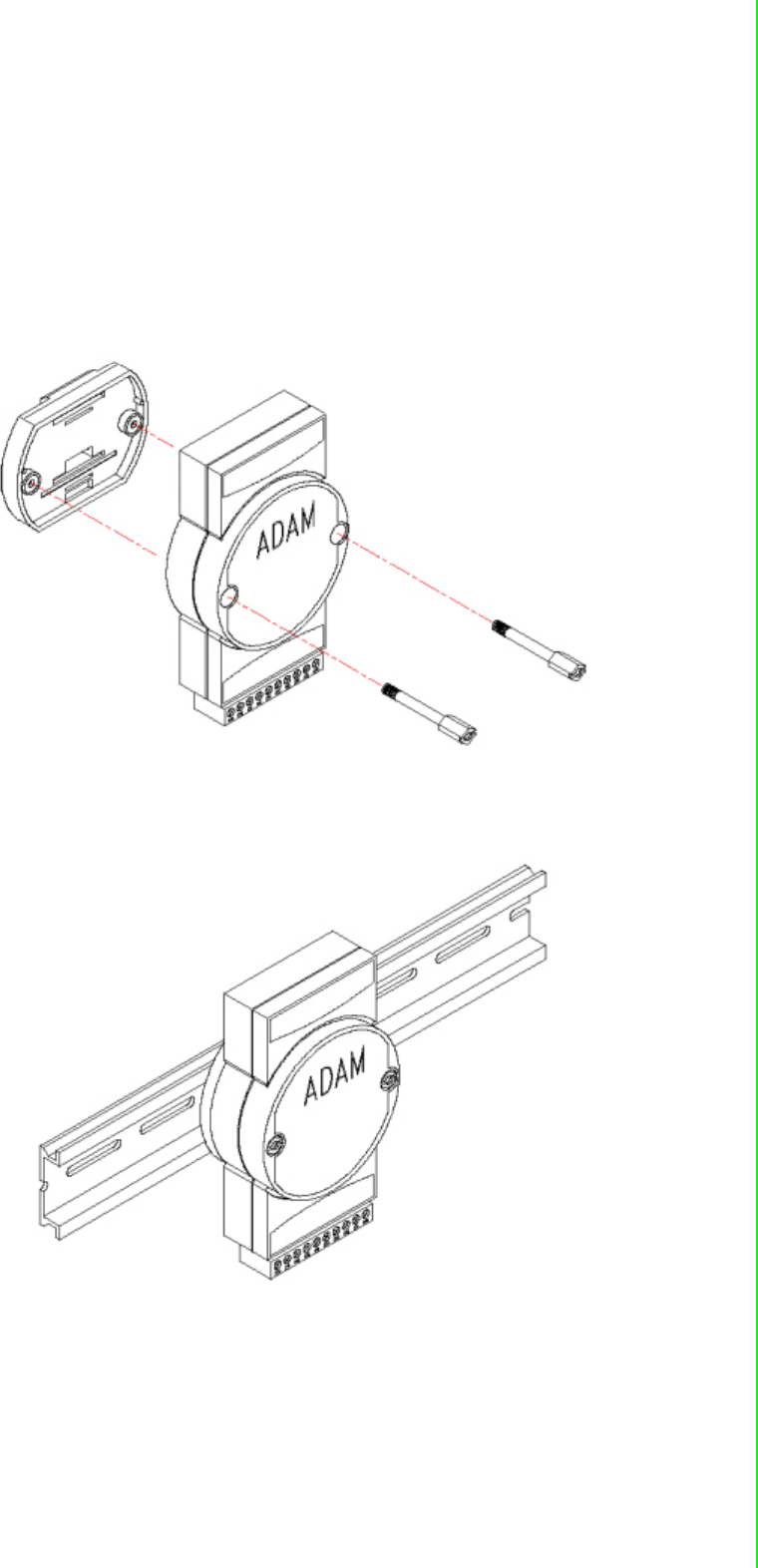
1.4.1 Panel Mounting
Each ADAM-2000 Module is packed with a plastic panel mounting bracket. Users
can refer the dimensions of the bracket to configure an optimal placement in a panel
or cabinet. Fix the bracket first, then, fix the ADAM-2000 module on the bracket.
Figure 1.5 Panel Mounting Dimensions
13 ADAM-2000 Series User Manual
Chapter 1 Understanding Your System
1.4.2 DIN-rail Mounting
The ADAM-2000 module can also be secured to the cabinet by using mounting rails.
Fix the ADAM-2000 module with the DIN-rail adapter as Figure 1.6. Then secure it on
the DIN-rail as Figure 1.7. If you mount the module on a rail, you should also consider
using end brackets at each end of the rail. The end brackets help keep the modules
from sliding horizontally along the rail.
Figure 1.6 Fixing ADAM-2000 to DIN rail adaptor
Figure 1.7 Fixed ADAM-2000 to DIN rail
ADAM-2000 Series User Manual 14
1.5 Wiring & Connections
This section provides basic information of wiring the power supply, I/O units, commu-
nication units, and network connection.
1.5.1 Power Supply Wiring
You can choose power supply type with 3 types: external power terminal, USB port,
and battery for ADAM-2520Z gateway, other devices can use external power or bat-
tery to get power.
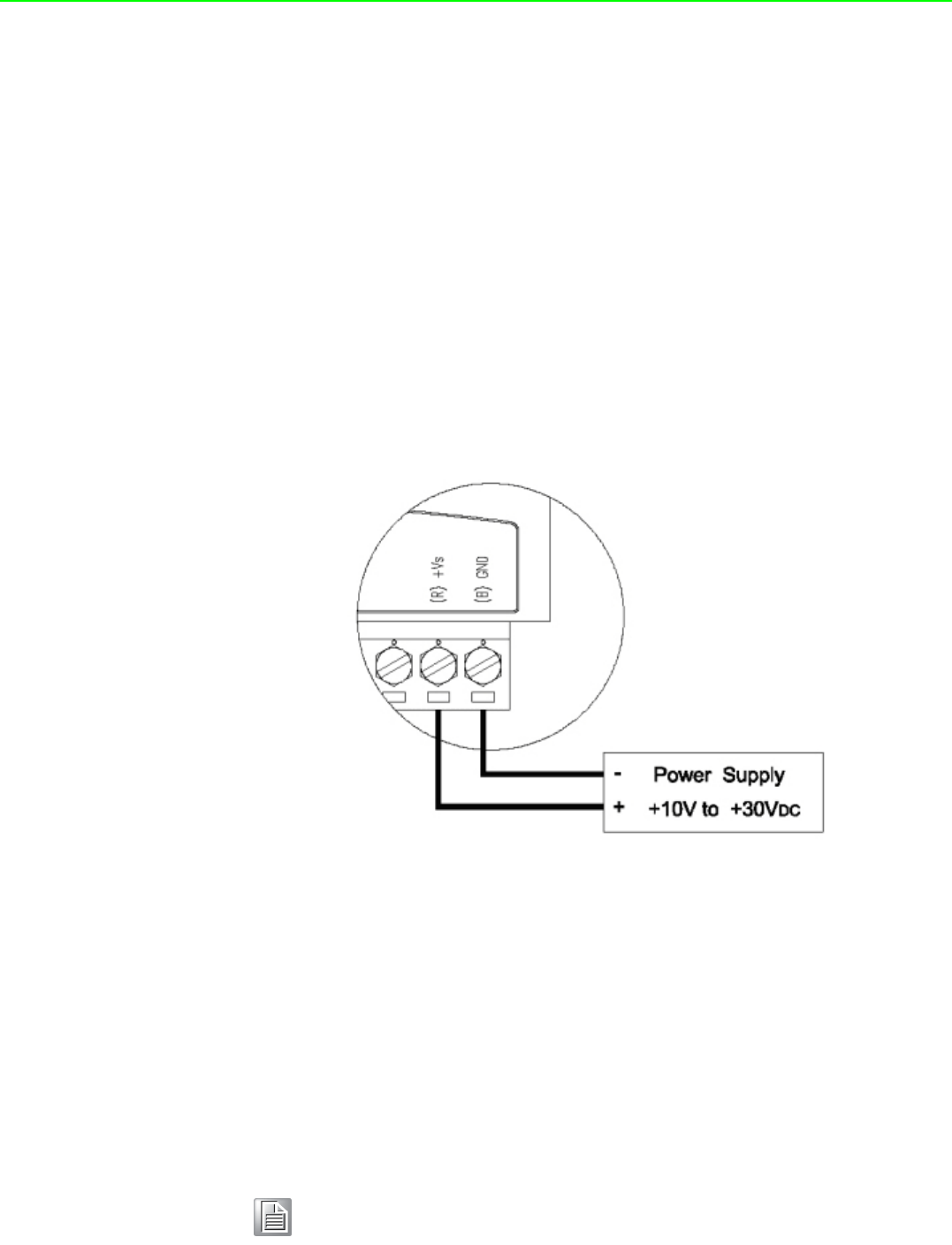
1.5.1.1 External Power Input
Although the ADAM-2000 systems are designed for a standard industrial unregulated
24 VDC power supply, they accept any power unit that supplies within the range of
+10 to +30 VDC. The power supply ripple must be limited to 200mV peak-to-peak,
and the immediate ripple voltage should be maintained between +10 and +30 VDC.
Screw terminals +Vs and GND are for power supply wiring.
Figure 1.8 Power Wiring Diagram
1.5.1.2 ADAM-2520Z Basic Configuration with USB Power Supply
To use the USB cable as a power supply from a PC, connect the A Type USB con-
nector to the computer and the other end (USB Type B) to the ADAM-2520Z Gate-
way.
1.5.1.3 Battery Power Slot
The ADAM-2000 series can be powered by batteries. Remove the name plate in the
front of the ADAM-2000 series device and install 2 AA batteries for backup power or
standard operation (depends on the power consumption of the devices). The ADAM-
2000 is powered by batteries only if the external power is not available.
Note! The batteries will not be charged when using external input power.

15 ADAM-2000 Series User Manual
Chapter 1 Understanding Your System
1.5.2 I/O Module Wiring
The system uses a plug-in screw terminal block as the interface between I/O mod-
ules and external devices. When connecting external devices to the I/O modules, fol-
lows the guideline below.
1. The maximum wire diameter allowed for the terminal block is 0.5 mm to 2.5 mm.
2. Always use an integrity wire.
3. Keep wires as short as possible.
4. Use wire trays or wire holders to secure wires.
5. Avoid running wires close to high energy wiring.
6. Keep input wiring and output wiring apart.
7. Avoid any sharp bend to the wires.
8. Follow the (+) and (-) symbols on the side panel to wire correctly.
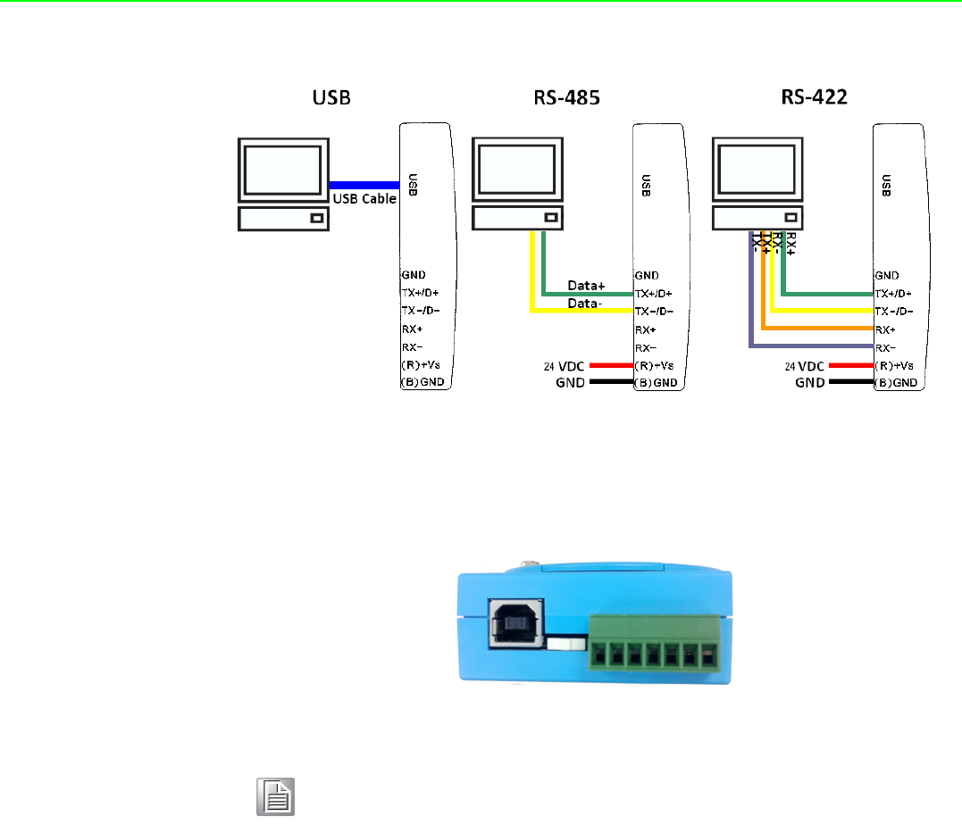
1.5.3 Communication Wiring
In a WPAN, only the Gateway needs to connect to a host. The ADAM-2520Z is the
Wireless Sensor Network Modbus RTU Gateway of the ADAM-2000 series and pro-
vides RS-422/485 and USB interfaces to connect to host. Users can choose one of
the interfaces by pushing the switch to RS-422/485 or USB position.
Figure 1.9 RS-422/485 and USB interface of ADAM-2520Z.
Note! If both external power input and battery power exist at the same time,
that external power will have high priority of main power source.
Note! ADAM-2510Z router and ADAM-2520Z gateway are always in normal
transmission mode during operation, and which power consumption will
be higher than other end devices to shorten battery life, therefore, sug-
gest ADAM-2510Z and ADAM-2520Z adopt external power input for
main power source and battery power for backup power source.
ADAM-2000 Series User Manual 16
Figure 1.10 Wiring Diagram for ADAM-2520Z
When you want to set up ADAM-2520Z gateway, please see as a wireless receiver to
use USB or RS-485 to do data transfer between router or end-device.
Note! On the base of ADAM-2520Z:
1. Move the switch to the left to select USB as main communication
interface.
2. Move the switch to the right to select RS-485 as main communica-
tion interface.
For ADAM-2520Z, we recommend user to choose power source accord-
ing to its communication interface. Please avoid the operation that insert
USB power source and external power source at the same time.

Chapter 2
2Selecting Your
Hardware
ADAM-2000 Series User Manual 18
2.1 Selecting an ADAM-2000 Module
2.1.1 Selecting a Communication Module
Communication modules are fundamental when needing to perform data acquisition
and control Wireless Sensor Networks systems. There are two types of communica-
tions modules: the coordinator and the router.
A coordinator is essential to associate an Wireless Personal Area Network (WPAN)
and as a data collector of the WPAN. Only one coordinator available in a specified
WPAN of a specified RF channel. A coordinator also acts as a gateway to translate
data packets between two different networks.
The router is optional in a PAN. The major function of a router is to repeat the wire-
less signal to improve the LQI. With routers, a PAN can be easily extended. More
routers in a PAN means larger coverage and capacity of the network.
Communication Module ADAM-2520Z, ADAM-2510Z
I/O Module ADAM-2017PZ, ADAM-2051Z, ADAM-2051PZ
Sensor Module ADAM-2031Z
Table 2.1: Communication Module Selection Guidelines
Choose this communication module: Description
Router Routers as a wireless signal repeater extends the
transmission range and communication quality
Gateway
A gateway collects wireless data from the end
node and translate to other communication proto-
cols, such as Modbus RTU.

19 ADAM-2000 Series User Manual
Chapter 2 Selecting Your Hardware
2.1.2 Selecting an I/O
To organize an ADAM-2000 series remote data acquisition and control system, you
need to select proper I/O or sensor modules to connect to field devices or processes
that you have previously determined.
2.1.3 Selecting a Sensor Module
Table 2.2: I/O Selection Guidelines
Choose this I/O
module:
For these types of field devices or
operations (examples):
Description:
Digital Input Node
Selector switches Push buttons
Photoelectric eyes
Limit switches
Circuit breakers
Proximity switches
Level switches
Motor starter contacts
Relay contacts
Thumb wheel switches
Input modules sense:
On/Off signals or Open/
Closed signals.
Analog Input Node
Thermocouple signals
RTD signals
Temperature transducers,
Pressure transducers
Load
Cell transducers
Humidity transducers
Flow transducers,
Potential meters
Convert continuous
analog signals into digital
input values for host device
Table 2.3: Sensor Mode Selection
Choose this
I/O module:
For these types of field devices or
operations (examples):
Description:
Sensors Node Temperature measurement
Humidity measurement
Directly measure the physical signal
without any conversion.

ADAM-2000 Series User Manual 20
2.2 Selecting an Operator Interface
To complete your data acquisition and control system, selecting an operator interface
is necessary. Adopting the Modbus protocol, ADAM-2000 series I/O modules exhibit
high ability in system integration for various applications. For reading the real-time
status of ADAM-2000 series modules anywhere without any engineering effort, there
is a lot of third-party Modbus software available.
To integrate ADAM-2000 series I/O with HMI, Human Machine Interface, software in
a SCADA, Supervisory Control and Data acquisition, system, there are a lot of HMI
software packages which support Modbus driver.
Advantech Studio
Advantech WebAccess
Wonderware InTouch
Intellution Fix of I-Fix
Any other software which supports the Modbus protocol

Chapter 3
3Module Introduction

ADAM-2000 Series User Manual 22
3.1 Communication Modules
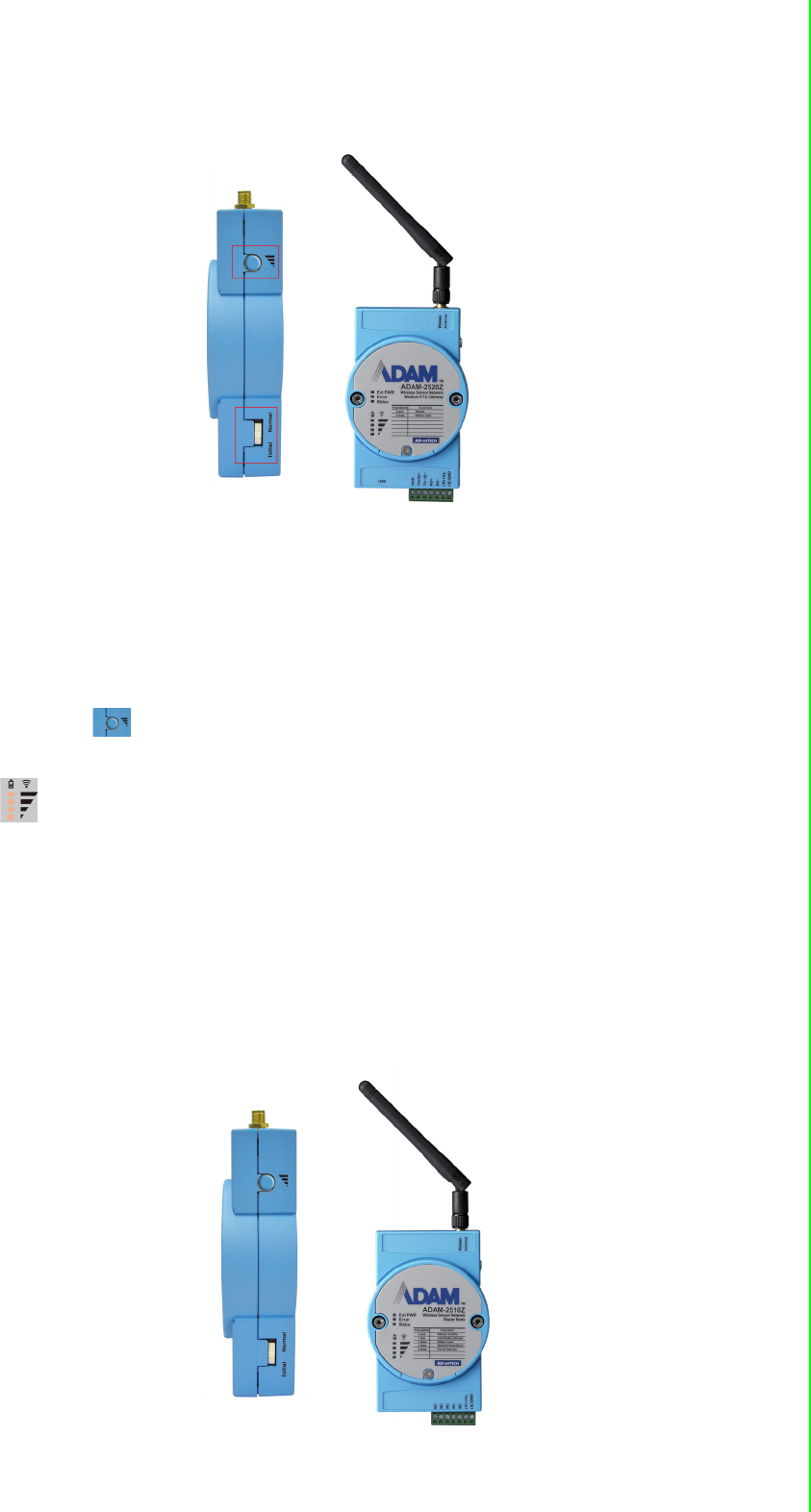
3.1.1 ADAM-2510Z
Wireless Sensor Network Router Node
ADAM-2510Z is a wireless signal repeater / router which is used to extend communi-
cation range between the coordinator/gateway and the end device.
3.1.1.1 ADAM-2510Z Specifications
Wireless:
IEEE Standard: IEEE 802.15.4
Modulation Type: DSSS (OQPSK)
Frequency Band: ISM 2.4GHz (2.4 GHz ~ 2.4835 GHz)
Channels: 11-26
RF Data Rate: 250 Kbps
Transmit Power: 19 ± 1dBm
Receiver Sensitivity: -97dBm
Antenna Type: Dipole
Antenna Gain: 2 dBi
Outdoor Range: 1000 m (Line of Sight)
Topology: Star/ Tree/ Mesh
Function: Router
General:
Connectors:1x plug-in terminal block (#14~22 AWG)
Power Input: Unregulated 10 ~ 30 VDC
Battery Input: 2 x AA Batteries
Power Consumption:
–0.8 W @ 24 VDC
–0.3 W @ 3 VDC (2 x AA Batteries)
Operating Humidity: 20 ~ 95% RH
Storage Humidity: 0 ~ 95% RH
Operating Temperature:
–External Power -20°C ~ 70°C (-4°F ~ 157.9°F)
–Battery Power 0°C ~ 50°C (32°F ~ 122°F)
Storage Temperature:-40°C ~ 85°C (-40°F ~ 185°F)
Note! ADAM-2510Z router and ADAM-2520Z gateway are always in normal
transmission mode during operation, and which power consumption will
be higher than other end devices to shorten battery life, therefore, sug-
gest ADAM-2510Z and ADAM-2520Z adopt external power input for
main power source and battery power for backup power source.

23 ADAM-2000 Series User Manual
Chapter 3 Module Introduction
3.1.2 ADAM-2520Z
Wireless Sensor Network Modbus RTU Gateway
The ADAM-2520Z is designed as a gateway to translate the IEEE 802.15.4 WPAN to
Modbus Network. In a WPAN, the ADAM-2520Z works as a coordinator to collect and
translate data from end devices to host PC.
3.1.2.1 Specifications
Wireless:
IEEE Standard: IEEE 802.15.4
Modulation Type: DSSS (OQPSK)
Frequency Band: ISM 2.4GHz (2.4 GHz ~ 2.4835 GHz)
Channels: 11-26
RF Data Rate: 250 Kbps
Transmit Power: 19 ± 1dBm
Receiver Sensitivity: -97 dBm
Antenna Type: Dipole
Antenna Gain: 2 dBi
Outdoor Range: 1000 m (Line of Sight)
Topology: Star/ Tree/ Mesh
Network Capacity: 32 nodes (Routers & End Devices)*
Range Extenders: Maximum 5 Hops
Function: Coordinator
*Note: Based on user's configuration
General:
Connector:
–1x plug-in terminal block (#14-22 AWG)
–1x USB-type A connector (type A to B cable provide)
Protocol: Modbus RTU
Baud Rate: 2400~115200bps
Power Input: Unregulated10 ~ 30 VDC
Battery Input: 2 x AA Batteries
Power Consumption:
–0.8 W @ 24 VDC
–0.5 W @ 5 VDC (USB)
–0.3 W @ 3 VDC (2 x AA Batteries)
Operating Humidity: 20 ~ 95% RH
Storage Humidity: 0 ~ 95% RH
Operating Temperature:
–External Power -20°C ~ 70°C (-4°F ~ 157.9°F)
–Battery Power 0°C ~ 50°C (32°F ~ 122°F)
Storage Temperature: -40°C ~ 85°C (-40°F ~ 185°F)
Note! ADAM-2510Z router and ADAM-2520Z gateway are always in normal
transmission mode during operation, and which power consumption will
be higher than other end devices to shorten battery life, therefore, sug-
gest ADAM-2510Z and ADAM-2520Z adopt external power input for
main power source and battery power for backup power source.

ADAM-2000 Series User Manual 24
3.2 I/O and Sensor Modules
3.2.1 ADAM-2017PZ
Wireless Sensor Network 6-ch Analog Input Node
The ADAM-2017PZ is an analog input data acquisition module with 6 channels to
measure the voltage and current.
3.2.1.1 Specifications
Wireless:
IEEE Standard: IEEE 802.15.4
Modulation Type: DSSS (OQPSK)
Frequency Band: ISM 2.4GHz (2.4 GHz ~ 2.4835 GHz)
Channels: 11-26
RF Data Rate: 250 Kbps
Transmit Power: 16 dBm (max peak power)
Receiver Sensitivity: -97 dBm
Antenna Type: Dipole
Antenna Gain: 2 dBi
Outdoor Range: 1000 m (Line of Sight)
Topology: Star / Tree / Mesh
Transmission Interval: 1 second ~ 24 hours
Function: End Device
General:
Connector: 1x plug-in terminal block (#14-22 AWG)
Power Input: Unregulated 10 ~ 30 VDC
Battery Input: 2 x AA Batteries
Power Consumption: 0.5 W @ 24 VDC/ 16mA
–420 uW @ 3 VDC(1 minute Tx interval with 2 x AA Batteries)
–240 uW @ 3 VDC (2 minute Tx interval with 2 x AA Batteries)
–150 uW @ 3 VDC (5 minute Tx interval with 2 x AA Batteries)
* Battery Peak Power Consumption: 50mA
Operating Humidity: 20 ~ 95% RH
Storage Humidity: 0 ~ 95% RH
Operating Temperature:
–External Power -20°C ~ 70°C (-4°F ~ 157.9°F)
–Battery Power 0°C ~ 50°C (32°F ~ 122°F)
Storage Temperature: -40°C ~ 85°C (-40°F ~ 185°F)
Note! ADAM-2017PZ's power consumption will be higher than other end
devices to shorten battery life, therefore, suggest ADAM-2017PZ adopt
external power input for main power source and battery power for
backup power source.
This device should be installed and operated with minimum distance 20cm between
the radiating element of this device and the user
25 ADAM-2000 Series User Manual
Chapter 3 Module Introduction
Analog Input
Channels: 6 (differential/Non-Isolation)
Input Impedance: > 10 MΩ (voltage) 120 Ω (current)
lnput Type: mV, V, mA (Configure Different Range for Each Channel)
Input Max: Voltage: +/-15V
Common Mode Voltage: Up to 10VDC
lnput Range: ±150 mV, ±500 mV, ±1 V, ±5 V, ±10 V, ±20 mA, 0-20 mA, 4-20 mA
Accuracy: ±0.1% or Better (voltage) at 25°C, ±0.2% or Better (current) at 25°C
Span Drift: ±30 ppm/°C
Zero Drift: ±22 μV/°C
Voltage Resolution:16 bit; ±150 mV, ±500 mV, ±1 V, ±5 V, ±10 V
Current Resolution:15 bit; ±20 mA
14 bit; 0 ~ 20 mA
13.5 bit; 4 ~ 20 mA
Sampling Rate: 12 sample/second (total)
CMR @ 50/60 Hz 100 dB
NMR @ 50/60 Hz 65 dB
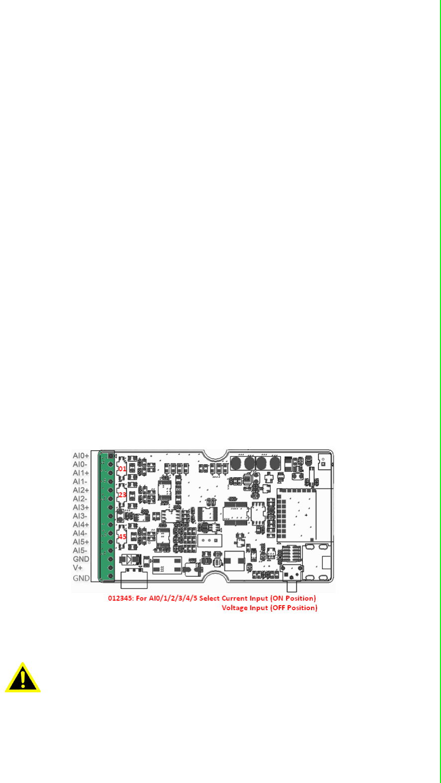
3.2.1.2 Connector Pin Define & Switch
Users can configure the switch define by the channel switch for each channel on
PCB (refer to the Figure below to see its location):
Switch:
ON: ADAM-2017PZ: Current Input Mode
OFF: ADAM-2017PZ: Voltage Input Mode
Warning! When change analog input type please always disconnect the power
and analog input from your module whenever you are working on it, do
not change switch position while the power is on.
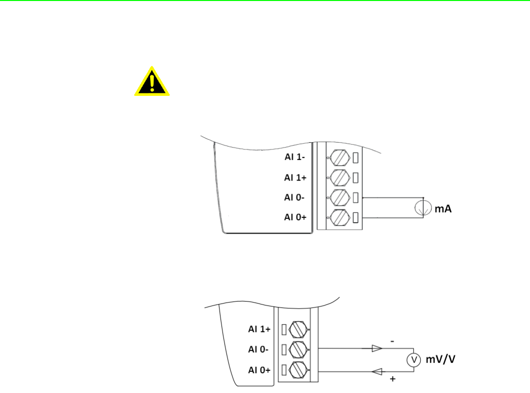
ADAM-2000 Series User Manual 26
Built-in 120 Ohm Resister (Current)
Figure 3.1 Current Input Wiring Diagram of ADAM-2017PZ
Figure 3.2 Voltage Input Wiring Diagram of ADAM-2017PZ
Warning! Incorrect analog input configuration may cause device damage. After
change analog input switch of channel please change correct input
range for each channel through AdamApax .NET utility before you con-
nect analog input signal to the module.

27 ADAM-2000 Series User Manual
Chapter 3 Module Introduction
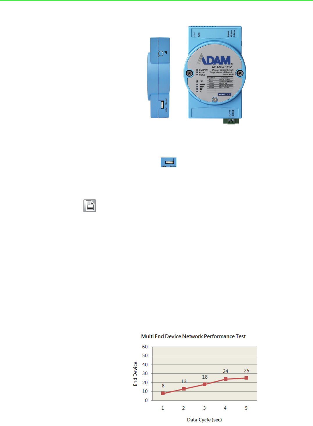
3.2.2 ADAM-2031Z
Wireless Sensor Network Temperature and Humidity Sensor Node
The ADAM-2031Z is an end device embedded sensors to measure the temperature
and humidity physical signal.
3.2.2.1 Specifications
Wireless:
IEEE Standard: IEEE 802.15.4
Modulation Type: DSSS (OQPSK)
Frequency Band: ISM 2.4GHz (2.4 GHz ~ 2.4835 GHz)
Channels: 11-26
RF Data Rate: 250 Kbps
Transmit Power: 3±1 dBm
Receiver Sensitivity: -97dBm
Antenna Type: Dipole
Antenna Gain:0 dBi
Outdoor Range: 110 m (Line of Sight)
Transmission Interval: 1 second ~ 24 hours
Function: End Device
General:
Connector: 1x plug-in terminal block (#14-22 AWG)
Power Input: Unregulated10 ~ 30 VDC
Battery Input: 2 x AA Batteries
Power Consumption:
–0.3 W @ 24 VDC
–420 uW @ 3 VDC(1 minute Tx interval with 2 x AA Batteries)
–240 uW @ 3 VDC (2 minute Tx interval with 2 x AA Batteries)
–150 uW @ 3 VDC (5 minute Tx interval with 2 x AA Batteries)
* Battery Peak Current Consumption: 50mA
* The battery life for 2 x AA 1.5V LR6 Alkaline batteries is 1 year, with 1 minute
sampling interval.
Operating Humidity: 20 ~ 95% RH (non-condensing)
Storage Humidity: 0 ~ 95% RH
Operating Temperature:-20°C ~ 70°C (-4°F ~ 157.9°F)
Storage Temperature: -40°C ~ 85°C (-40°F ~ 185°F)
Temperature Sensor Input
Operating Range: -20°C ~ 70°C (-4°F ~ 157.9°F)
Resolution: 0.02°C (0.04°F)
Accuracy: ±1.0°C (33.8°F)(±0.5°C @ 0 ~ +35°C)
Repeatability: ±0.1°C (0.4°F)
Response Rate: ±1°C/min
Long Term Drift: < 0.04°C/Year (0.07°F/Year)
Humidity Sensor Input
Operating Range: 0 ~ 100% RH
Resolution: 0.15% RH
Accuracy: ±3.0% RH
Repeatability: ±0.1% RH

ADAM-2000 Series User Manual 28
Response Time: 8 seconds (Achieving 63% of a step function)
Long Term Drift: 0.5% RH/Year

29 ADAM-2000 Series User Manual
Chapter 3 Module Introduction
3.2.3 ADAM-2051Z
Wireless Sensor Network 8-ch Digital Input Node
The ADAM-2051Z works as an end device provides 8-ch digital input.
3.2.3.1 ADAM-2051Z Specifications
Wireless:
IEEE Standard: IEEE 802.15.4
Modulation Type: DSSS (OQPSK)
Frequency Band: ISM 2.4GHz (2.4 GHz ~ 2.4835 GHz)
Channels: 11-26
RF Data Rate: 250 Kbps
Transmit Power: 3±1 dBm
Receiver Sensitivity: -97 dBm
Antenna Type: Dipole
Antenna Gain: 2 dBi
Outdoor Range: 110 m (Line of Sight)
Topology: Star / Tree / Mesh
Transmission Interval: 1 second ~ 24 hours
Function: End Device
General:
Connector: 1x plug-in terminal block (#14-22 AWG)
Power Input: Unregulated 10 ~ 30 VDC
Battery Input: 2 x AA Batteries
Power Consumption:
–0.3 W @ 24 VDC
–380 uW @ 3 VDC (1 minute Tx interval with 2 x AA Batteries)
–220 uW @ 3 VDC (2 minute Tx interval with 2 x AA Batteries)
–130 uW @ 3 VDC (5 minute Tx interval with 2 x AA Batteries)
* Battery Peak Current Consumption: 50mA
* The battery life for 2 x AA 1.5V LR6 Alkaline batteries is 1 year, with 1 minute
sampling interval.
Operating Humidity: 20 ~ 95% RH
Storage Humidity: 0 ~ 95% RH
Operating Temperature: -20°C ~ 70°C (-4°F ~ 157.9°F)
Storage Temperature: -40°C ~ 85°C (-40°F ~ 185°F)
Digital Input:
Channels: 8
Input Resistance: 10 KOhm
Supports wet and dry contacts
Input Level:
–Logical level 0: 0 ~ 0.8 Vmax
–Logical level 1:2.0 Vmin ~ 5.0 Vmax

ADAM-2000 Series User Manual 30
3.2.4 ADAM-2051PZ
Wireless Sensor Network 8-ch Digital Input Node with Power Amplifier
The ADAM-2051PZ works as an end device provides 8-ch digital input with wireless
power amplifier for better transmission power and receive sensitivity to enhance
communication range and quality.
3.2.4.1 ADAM-2051PZ Specifications
Wireless:
IEEE Standard: IEEE 802.15.4
Modulation Type: DSSS (OQPSK)
Frequency Band: ISM 2.4GHz (2.4 GHz ~ 2.4835 GHz)
Channels: 11-26
RF Data Rate: 250 Kbps
Transmit Power: 19 ±1 dBm
Receiver Sensitivity: -97 dBm
Antenna Type: Dipole
Antenna Gain: 2 dBi
Outdoor Range: 1000 m (Line of Sight)
Topology: Star / Tree / Mesh
Transmission Interval: 1 second ~ 24 hours
Function: End Device
General:
Connectors: 1x Plug-in terminal block (#14-22 AWG)
Power Input: Unregulated 10 ~ 30 VDC
Battery Input: 2 x AA Batteries
Power Consumption:
–0.3 W @ 24 VDC
–380 uW @ 3 VDC (1 minute Tx interval with 2 x AA Batteries)
–220 uW @ 3 VDC (2 minute Tx interval with 2 x AA Batteries)
–130 uW @ 3 VDC (5 minute Tx interval with 2 x AA Batteries)
* Battery Peak Current Consumption: 60mA
* The battery life for 2 x AA 1.5V LR6 Alkaline batteries is 1 year, with 1 minute
sampling interval.
Operating Humidity: 20 ~ 95% RH
Storage Humidity: 0 ~ 95% RH
Operating Temperature:-20°C ~ 70°C (-4°F ~ 157.9°F)
Storage Temperature: -40°C ~ 85°C (-40°F ~ 185°F)
Digital Input:
Channels: 8
Input Resistance: 10 KOhm
Supports wet and dry contacts
Input Level:
–Logical level 0: 0 ~ 0.8 Vmax
–Logical level 1: 2.0 Vmin ~ 5.0 Vmax
31 ADAM-2000 Series User Manual
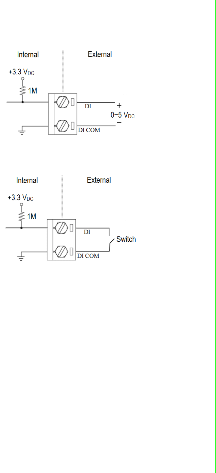
Chapter 3 Module Introduction
Application Wiring:
Figure 3.3 ADAM-2051Z/2051PZ Wet Contact Diagram
Figure 3.4 ADAM-2051Z/2051PZ Dry Contact Diagram

ADAM-2000 Series User Manual 32

Chapter 4
4Installation Guide

ADAM-2000 Series User Manual 34
4.1 Determining the Proper Environment
Prior to installing ADAM-2000 series modules, please check the following.
4.1.1 Package Contents
Unpack the package and make sure that the contents include:
ADAM-2000 series module
2 dBi antenna (ADAM-2520Z, ADAM-2510Z, ADAM-2051PZ only)
2 x Mounting kits
ADAM-2000 series CD (User manual, datasheet, Quick start guide and AdamA-
pax .NET Utility)
4.1.2 System Requirements
IBM PC compatible computer with at least 486 CPU (Pentium recommended)
Microsoft Windows 2000, XP, Vista and 7 (32/64Bit)
At least 32 MB RAM
20 MB of hard disk space available
VGA color monitor
CD-ROM or DVD-ROM
Mouse or other pointing devices
Power Supply for ADAM-2000 Series (+10 ~ +30 VDC Unregulated) or 2 AA bat-
teries
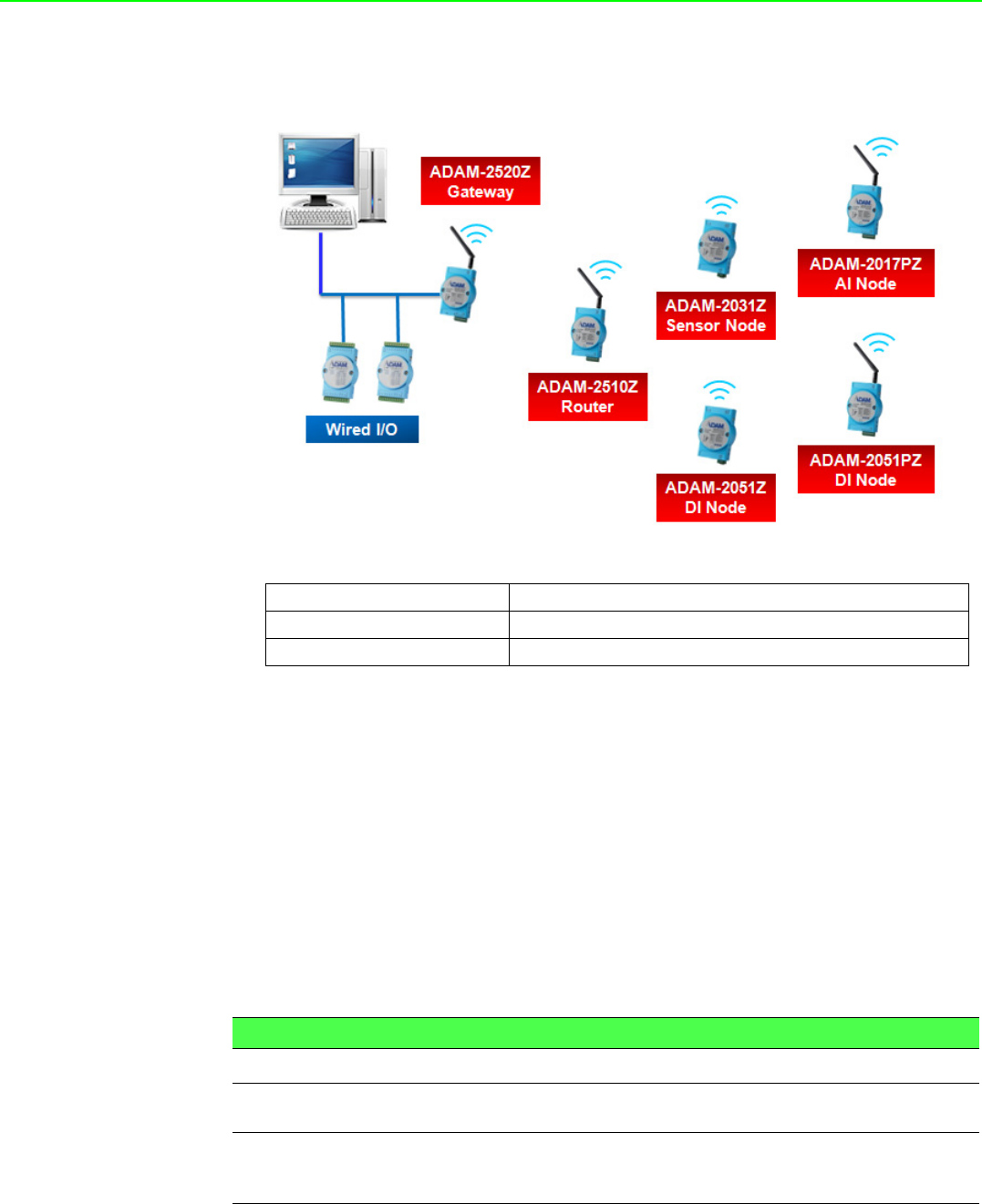
4.1.3 Perform a Wireless Sensor Network
Coordinator, Router and End Device are three basic elements of the Wireless Sensor
Network. Each of them has different functions. All the nodes have to set the same
PAN ID and RF channel to perform the communication.
A Coordinator is essential to associate a PAN of the Wireless Sensor Network in a
specific PAN ID and RF channel. It is also a data collector of the PAN and usually
works as a gateway to translate wireless data into any other data formats, such as
Modbus RTU.
A router is optional in a PAN. It works as a wireless repeater to enhance the wireless
signal strength and selects the optimistic path for a end node to route data back to
the coordinator. A PAN with routers can make the network work as tree or mesh
topology.
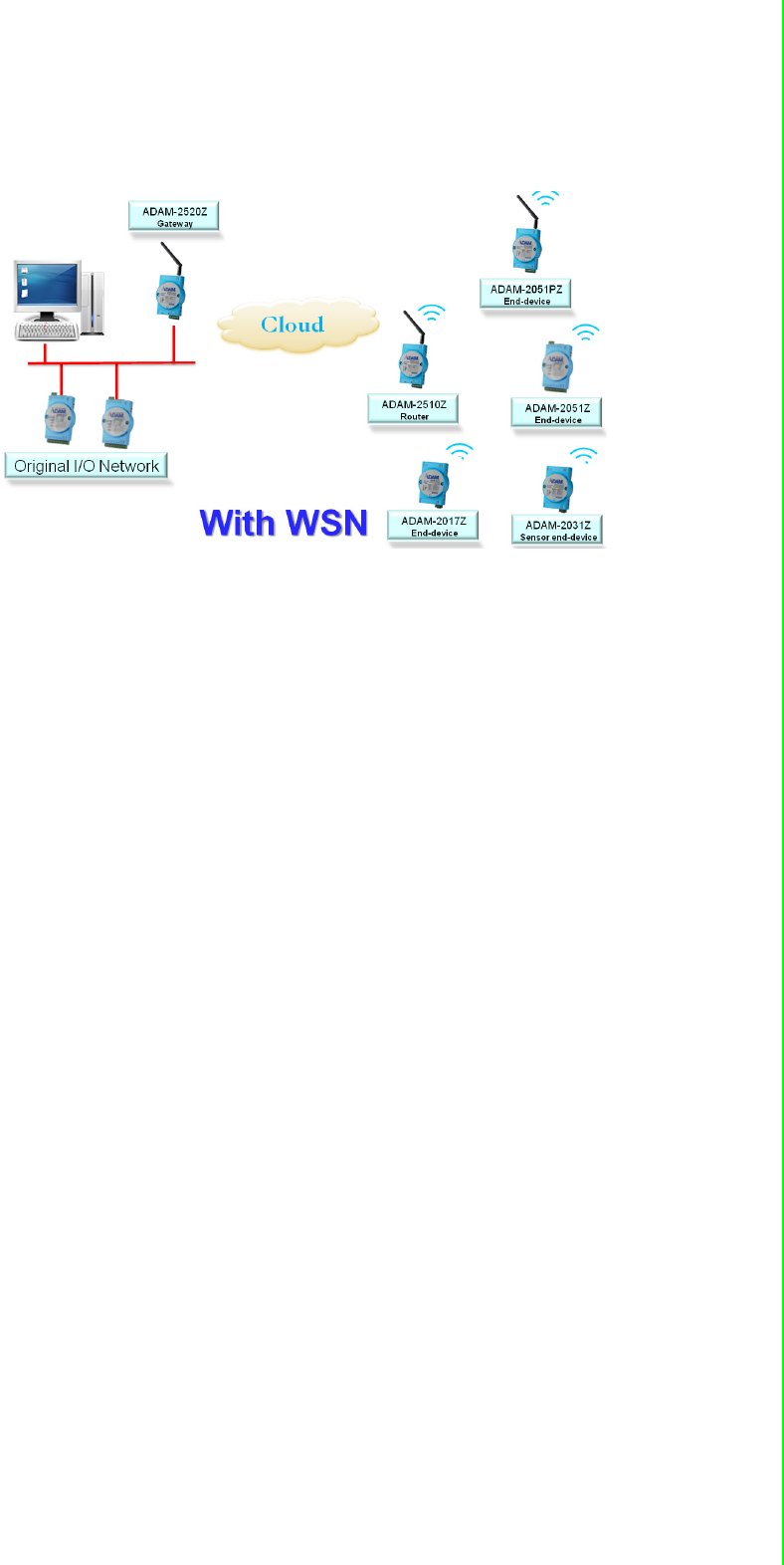
35 ADAM-2000 Series User Manual
Chapter 4 Installation Guide
An End Device (End Node) is the basic element to acquire the physical signals and
data from I/O, sensor and even communication interface. It can be designed for
many different functions and is possible for standalone applications by battery-power.
Figure 4.1 The Architecture of the Wireless Sensor Network
ADAM-2000 Series User Manual 36
4.2 Establish the Connection
4.2.1 Basic Installation
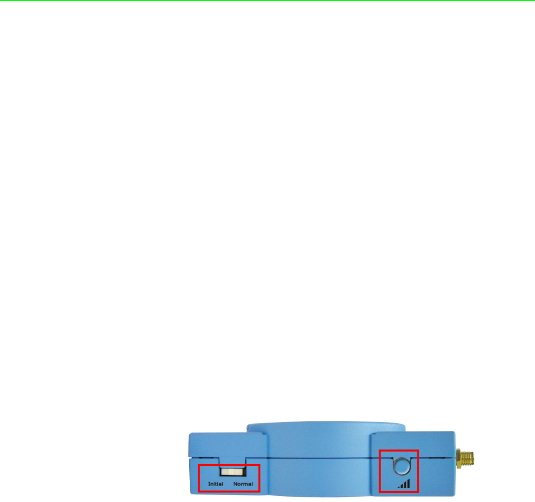
In the side of the ADAM-2000 series, users can find Mode Switch and Function
Button. The two hardware keys contain several combinations for device operations.
The default position of Mode Switch is set in the Initial Mode to configure the device
and establish connection for Normal Mode.
It is easily to use the ADAM-2000 series with default configuration. Push the Mode
Switch on the side of ADAM-2000 devices to Normal position then the PAN can be
operated to collect data from modules. The ADAM-2000 series also provides
advanced functions for further operations.
Initial Mode
The Initial Mode is for user to configure parameters of the ADAM-2000 devices.
While the device is in the Initial Mode, Status LED turns on.
1. Push the Mode Switch to the Initial position.
2. Open the AdamApax .NET Utility to search and configure the ADAM-2000
devices.
Normal Mode
After all the ADAM-2000 devices are configured in the same PAN ID and RF channel,
push the Mode Switch to Normal position to perform the Wireless Sensor Network.
Connection Steps in Initial Mode:
4.2.1.1 Coordinator
1. Power on.
2. All LEDs turn on for 0.5 second then turn off.
3. Status LED turns on, Error LED blinks.
4. Level Index turns on to indicate Pair ID 1. (Pair ID will automatically count if
there is a coordinator nearby.
5. Error LED turns off when it hosts a PAN.
37 ADAM-2000 Series User Manual
Chapter 4 Installation Guide
4.2.1.2 Router/End Device
Routers and End Devices must have to associate with corresponding Pair ID Coordi-
nator in Initial Mode to build up the wireless communication. The function is for
Router and End Devices only.
1. Power on.
2. All LEDs turn on for 0.5 second then turn off.
3. Press the Function Button 3 times to join a PAN with the default Pair ID 1.
4. Status LED turns on, Error LED blinks.
5. Level Index turns on to indicate Pair ID 1. (Pair ID needs to be properly
configured if there are coordinators. For advanced settings, please refer to sec-
tion 4.3)
6. If the Coordinator Pair ID is not 1, hold the Function Button for 2 seconds to
reboot your router or end-devices, then press Function Button 5 times to enter
Pair ID selection, the click N times according the Coordinator Pair ID, then hold
the Function Button for 2 seconds to confirm your setting, finally press the
Function Button 3 times to join a PAN.
7. Error LED turns off when it join a PAN.
ADAM-2000 Series User Manual 38
Once the Coordinator, Routers and End Devices are connected in the same Pair ID
then all devices can be configured through AdamApax .NET Utility for Normal Mode
operation. (For detailed operation and functionality of AdamApax .NET Utility, please
refer to Chapter 5.) Push the Mode Switch to the Normal position to reboot
the device to Normal Mode.
4.2.1.3 Router and End Device Connection Network limitation
When we adopt a large number of ADAM-2000 devices in one application architec-
ture, which may cause low network performance or data package transmission colli-
sion. Assume ADAM-2520Z like a funnel which receives data around routers and end
devices, if setting too fast transmission interval that will generate high data package
transmission collision during the transmission then affect network performance and
data receiving.
The images below comparisons between Multi-End Device performance and the
relationship between Multi-End Devices and Routers. Their purpose is to assist the
user in installing the ADAM-2000 devices in a proper network configuration and oper-
ation.
Figure 4.2 Multi-End Device Network performance
Note! To set up the Coordinator, Routers and End Devices, make sure they
are in the same mode, otherwise they can't be configured.

39 ADAM-2000 Series User Manual
Chapter 4 Installation Guide
Figure 4.3 Multi-End Device and Router Network Relationship
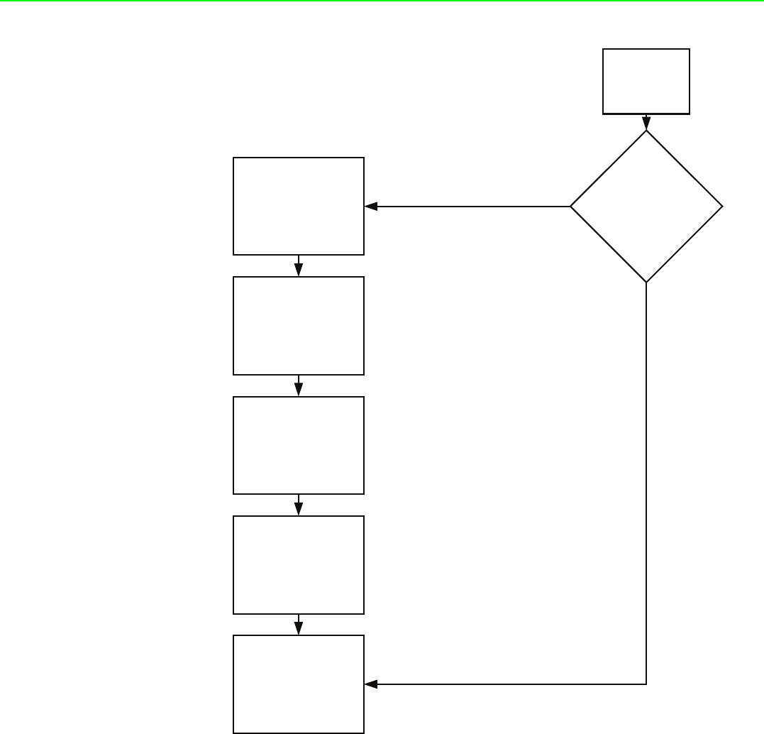
4.2.2 ADAM-2000 Series Installation Flowcharts
The following flowcharts are designed to tell you how to install the ADAM-2000 mod-
els.
4.2.2.1 ADAM-2000 Series Installation Overview
The section describes how to host a WPAN for the ADAM-2000 series. The coordina-
tor, end devices are basic component for the wireless data acquisition system. Rout-
ers are optional to enhance the network coverage and mesh mechanism. Please
refer to the following flowchart for the overview of the ADAM-2000 installation, config-
uration and operation.
ADAM-2000 Series User Manual 40
Figure 4.4 ADAM-2000 Installation Chart
Install power of
ADAM-2000
devices.
All ADAM-2000 devices
setup ready to perform a
PAN.
Coordinator host a PAN in
Initial Mode
Routers and End Devices
join the PAN in Initial Mode
Connect the coordinator to
the PC.
Open AdamApax .NET Utility
to configure the Coordinator,
Routers and End Devices for
Normal Mode.
Set the Coordinator, Routers
and End Devices to Normal
Mode. All the ADAM-2000
devices set in the same PAN
and RF channel will
automatically associate the
PAN for data acquisition.
No
Yes
41 ADAM-2000 Series User Manual
Chapter 4 Installation Guide
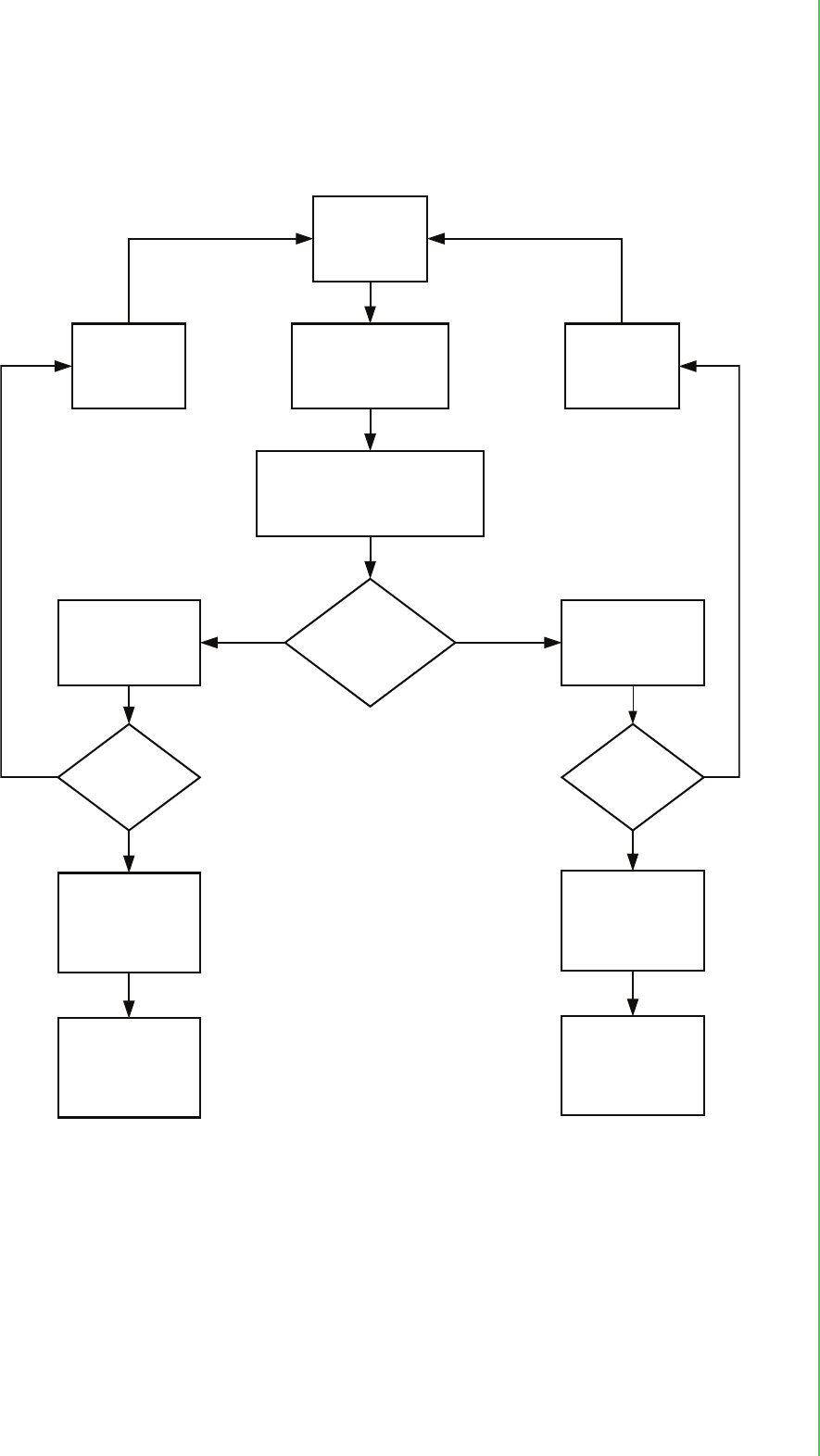
4.2.2.2 Coordinator Configuration Flowchart
The section tells the user how to setup the Coordinator to host a PAN for a wireless
sensor network.
Please refer to
Appendix B for
troubleshooting.
Please refer to
Appendix B for
troubleshooting.
Install Power
Connect to PC through
USB or RS-422/485
All LEDs turn On
(Green LED turns on while powering by
external/USB power)
Configured ready for
Normal Mode
Initial Mode:
Status LED turns on,
Error LED blinks.
Normal Mode:
Status LED turns off,
Error LED blinks.
Error LED turns off
Successfully host a
PAN with default PAN
ID and RF channel then
Amber LED turns on
indicating Pair ID.
Successfully host a
PAN with user defined
PAN ID and RF channel
then Amber LED turns
on indicating Modbus
ID.
Open AdamApax.NET
Utility to configure the
ADAM-2000 series,
refer to Chapter 5
for more information.
Collect and transmit
data/signal from end
nodes to host.
Error LED turns off
No Yes
No No
Yes
Yes
ADAM-2000 Series User Manual 42
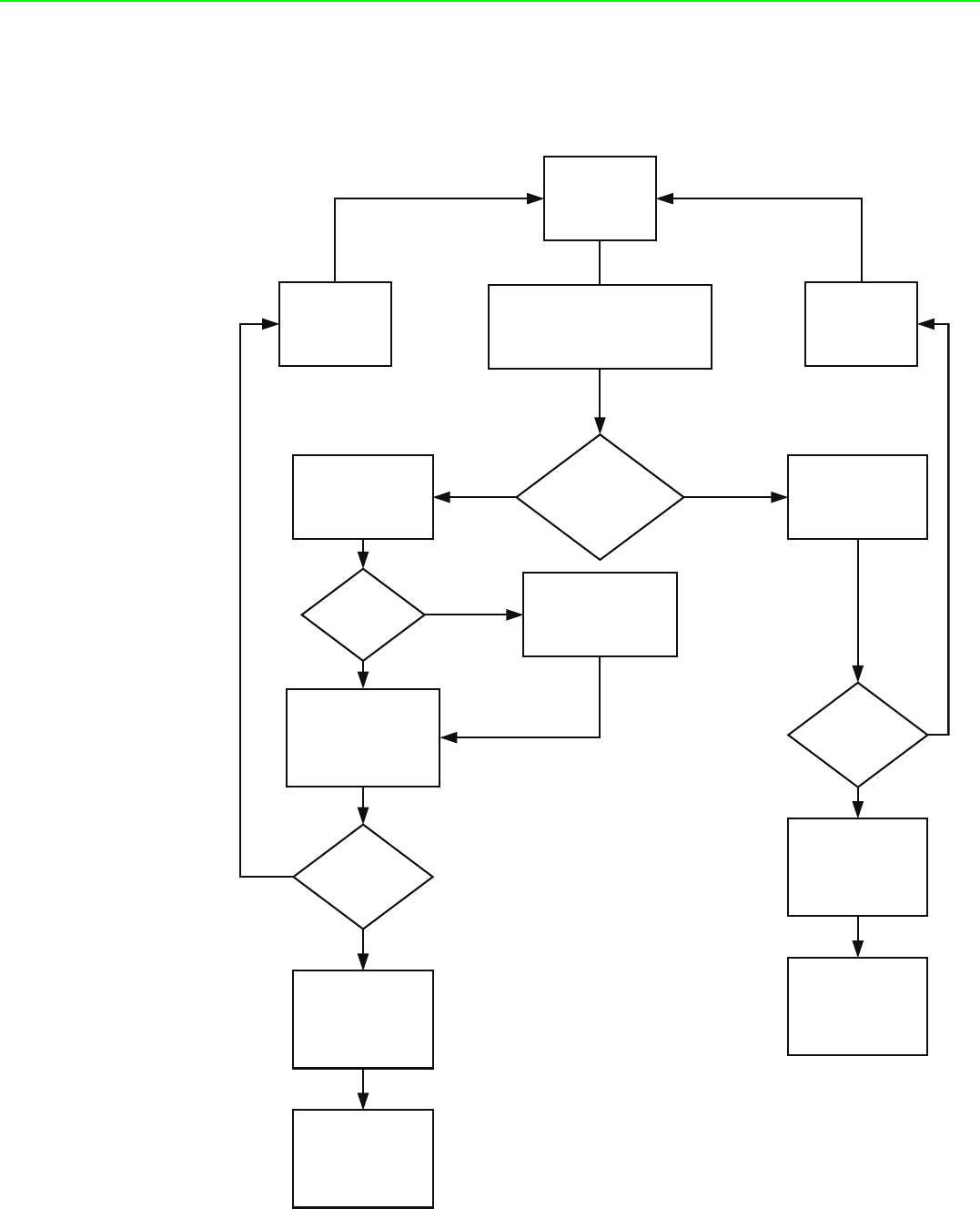
4.2.2.3 Router Configuration Flowchart
The section tells the user how to setup the Router to enhance the wireless communi-
cation range and coverage of a PAN for a wireless sensor network.
Install Power
Press Function Button 3
times to join the PAN.
Amber LED turns on.
Error LED blinks.
Please refer to
Appendix B for
troubleshooting.
Please refer to
Appendix B for
troubleshooting.
All LEDs turn On
(Green LED turns on while powering by
external power)
Configured ready for
Normal Mode
Initial Mode:
Status LED turns on
Normal Mode:
Status LED turns off,
Error LED blinks.
Error LED turns off
Successfully join a PAN
with default PAN ID and
RF channel. Amber
LED indicating Pair ID.
Successfully join a PAN
with user defined PAN
ID and RF channel.
Open AdamApax .NET
Utility to configure the
ADAM-2000 series,
refer to Chapter 5 for
more information.
Repeat and pass data/
signal from end nodes
to coordinator.
Error LED turns off
Join PAN with
Pair ID 1
Press Function Button 5
times to change Pair ID.
No Yes
No
No
No
Yes
Yes
Yes
43 ADAM-2000 Series User Manual
Chapter 4 Installation Guide
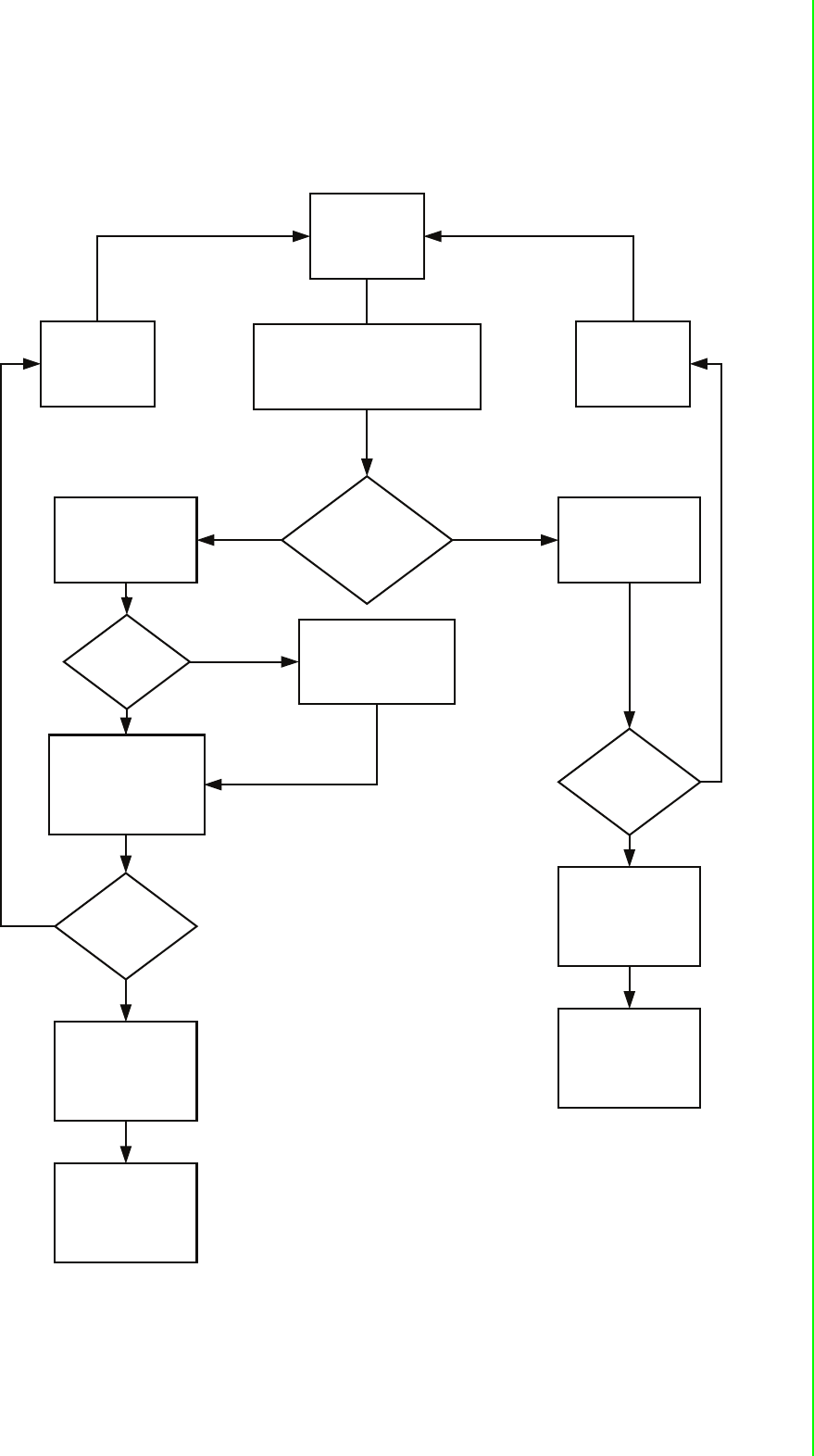
4.2.2.4 End Device Configuration Flowchart
The section tells the user how to setup the End Devices to do data acquisition of a
PAN for a wireless sensor network.
Install Power
Press Function Button 3
times to join the PAN.
Amber LED turns on.
Error LED blinks.
Please refer to
Appendix B for
troubleshooting.
Please refer to
Appendix B for
troubleshooting.
All LEDs turn On
(Green LED turns on while powering by
external/USB power)
Configured ready for
Normal Mode
Initial Mode:
Status LED turns on,
Normal Mode:
Status LED turns off,
Error LED blinks.
Error LED turns off
Successfully join a PAN
with default PAN ID and
RF channel. Amber
LED indicating Pair ID.
Successfully join a PAN
with user defined PAN
ID and RF channel.
Open AdamApax .NET
Utility to configure the
ADAM-2000 series,
refer to Chapter 5 for
more information.
Transmit data/signal to
Coordinator.
Error LED turns off
Join PAN with
Pair ID 1
Press Function Button 5
times to change Pair ID.
No Yes
No
No
No
Yes
Yes
Yes

ADAM-2000 Series User Manual 44
4.3 Advanced Functions
4.3.1 Link Quality Indicator
The LQI represents the wireless signal index and can assist the user to install the
ADAM-2000 devices in proper location for good communication quality. The LQI
function is only available for Router and End Devices. Press the Function Button
once and the Level Index in the front panel will turn on to indicate the level of LQI.
4.3.2 Battery Level
All ADAM-2000 devices are all designed to be used with batteries. Users can install 2
AA batteries for extended operation or back-up power. Press the Function Button
twice and the Level Index in the front panel will turn on to indicate the level of battery
power.
Table 4.1: Level of LQI
Level Index Conditions Description
3 LED ON, 1 LED Blink Excellent
2 LED ON, 1 LED Blink Good
1 LED ON, 1 LED Blink Normal
1 LED Blink Poor
No LED on, Error LED blinks No Signal
Table 4.2: Level of battery power
Level Index Conditions Description Percentage of
Battery
3 LED ON, 1 LED Blink Excellent 100%~ 81%
2 LED ON, 1 LED Blink Good 80%~ 61%
1 LED ON, 1 LED Blink Normal 60%~ 41%
1 LED Blink Poor 40%~ 21%
No LED on, Error LED blinks Low battery Below 21%

45 ADAM-2000 Series User Manual
Chapter 4 Installation Guide
4.3.3 Pairing
In the Initial Mode, Routers and End Devices must be associated with the corre-
sponding Coordinator. The function is for Router and End Devices only.
1. Press the Function Button 5 times to enter the change Pair ID mode.
2. Status LED blinks
3. Level Index LED turns on to indicate Pair ID.
4. Press the Function Button once to change Pair ID.
5. Press and hold the Function Button for over 2 seconds to save and confirm the
Pair ID.
6. Press the Function Button 3 times to associate with specific Pair ID Coordina-
tor.
7. Error LED turns off when it join a PAN.
4.3.4 Associating Devices
Routers and End Devices must have to associate with corresponding Pair ID Coordi-
nator in Initial Mode to build up the wireless communication. The function is for
Router and End Devices only.
1. Press the Function Button 3 times to join a PAN with specific Pair ID Coordina-
tor.
2. Status LED turns on, Error LED blinks.
3. Level LED turns on to indicate the Pair ID to associate with.
4. Error LED turns off when it joins a PAN.
4.3.5 Reboot
Press the Function Button for over 3 seconds to reboot the device.
4.3.6 Button Function Table
Table 4.3: Button Functions
Press Button Function
2 Seconds Confirm the Pair ID
3 Seconds Reboot
Once Link Quality Indicator
2 Times Battery Level
3 Times Network Association
5 Times Pair ID Selection

ADAM-2000 Series User Manual 46
4.4 Conduct a Site Survey
Performing a Site Survey before installing the WSN is a necessary procedure to
ensure reliable communication. The following description demonstrates the standard
process of Site Survey.
4.4.1 Before Going Onsite
1. Ask the customer for the maps and collect the information in previous chapter
the more the merrier.
2. Check with the customer for the possible position to install the coordinator.
3. Setup all modules
Prepare the following items:
–ADAM-2520Z *1
–ADAM-2510Z *8, it depends on the area of site, 8 router can organize two 5-
hop network
–ADAM-2051PZ *1
–2 AA batteries for the above modules
Set all modules in same PAN ID and RF Channel. The RF Channel suggests to
be set to channel 15 or 20 to avoid the interference of WLAN.
Set all modules' data cycle to 5 second.
Set all modules as individual ID address.
Install batteries for all modules.
Switch all modules to normal mode and use utility to check all modules are
work.
Switch all modules to initial mode and remove the batteries.
4.4.2 Onsite Survey
1. Setup Coordinator
When arriving the site, power up ADAM-2520Z with batteries and switch it to
normal mode.
Install ADAM-2520Z at the place that can be seen from most of the place or cor-
ner to ensure the signal can be easier to be accessed.
If possible, do not install on the concrete wall, heavy column, or girder.
The antenna should be vertical to the plane that going to install other modules.
2. Add Router
Install batteries to one of the ADAM-2051PZ, and switch it to normal mode.
Press the button of ADAM-2051PZ one time to check the link quality
Walk away from coordinator and keep checking the LQI until only one LED level
is on.
Add one router with batteries and work in normal mode at that position
Check the LQI of router 5 times to make sure a least one LED level is on.
Check the ADAM-2051PZ has full LED level at the same place, if only one LED
level is on, switch it to initial mode and then back to normal mode to re-register
the routing.
Walk away from the new added router and use the same way to add next router
until the position of end-devices that will install can access the network.

Chapter 5
5Software
Configuration Guide
ADAM-2000 Series User Manual 48
5.1 System Software Configuration Utility
The AdamApax .NET Utility software offers a graphical interface that helps you con-
figure the ADAM-2000 series. It is also very convenient to test and monitor your
remote data acquisition and control system. The following guidelines will give you
some brief instructions on how to use this Utility. Before installing the ADAM.NET
Utility, remember to first install .NET Framework 3.5 or later from Microsoft website.
5.2 Installing AdamApax .NET Utility Software
Advantech provides a free download of AdamApax .NET Utility software for module
operation and configuration. You can find the Utility installation file in the CD with your
module, or on our website at: http://www.advantech.com and click the Download
Area under Service & Support to get the latest version of the ADAM.NET Utility. Once
you download and setup the Utility software, there will be a shortcut of the Utility pro-
gram on the desktop.
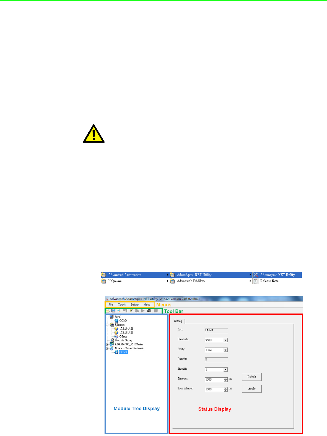
5.3 AdamApax .NET Utility Operation
After you have successfully installed AdamApax.NET Utility, there will be one short-
cut icon on the desktop. Double click the shortcut icon that you should be able to see
the operation window.
Figure 5.1 AdamApax .NET Utility Operation Window
Caution! 1. Make sure both coordination and devices are in Initial Mode
2. Ensure that you are using a minimum of Windows 2000, XP or
Windows 7
3. Before installing ADAM.NET Utility, you need to install the .NET
Framework 3.5 or later.

49 ADAM-2000 Series User Manual
Chapter 5 Software Configuration Guide
The operation window consists of four areas --- the Menus, the Toolbar, the Module
Tree Display Area and the Status Display Area.
Menus
The menus at the top of the operation window contain:
File Menu:
1. Open Favorite Group - You can configure your favorite group and save the con-
figuration into one file. Using this option, you can load your configuration file for
favorite group.
2. Save Favorite Group - You can configure your favorite group and save the con-
figuration into one file. Using this option, you can save your favorite group into
one configuration file.
3. Auto-Initial Group - If you want to have the same favorite group configuration
when you exit AdamApax .NET Utility and launch it again, you need to check
this option.
4. Exit - Exit AdamApax.NET Utility.
Tools Menu:
1. Search- Search all the ADAM-2000, ADAM-4000, ADAM-5000 and ADAM-6000
modules you connected.
2. Add Devices to Group - You can add ADAM-2000 modules to your favorite
group by this option. You need to select the device you want to add in the Mod-
ule Tree Display area (it will be described below) first, and then select this
option to add.
3. Print Screen - You can save current AdamApax .NET Utility screen into an
image file by this option.
Setup Menu:
1. Favorite Group - You can configure your favorite group including add one new
device, modify or delete one current device, sort current devices and diagnose
connection to one device.
2. Refresh COM and LAN node - AdamApax .NET Utility will refresh the serial and
LAN network connection situation.
3. Add COM Port Tree Nodes - This option is used to add serial COM ports in
AdamApax.NET Utility.
4. Show TreeView - Check this option to display the Module Tree Display area.
Help Menu:
1. Check Up-to-Date on the Web - Choose this option, it will automatically connect
to Advantech download website.You can download the latest utility there.
2. About AdamApax .NET Utility- Choose this option, you can see version of
AdamApax .NET Utility installed on your computer.
Note! The Favorite Group function is for the ADAM-4000, ADAM-5000/TCP and
ADAM-6000

ADAM-2000 Series User Manual 50
Toolbar
There are 8 graphical icons on the toolbar for 8 common used options of Menus. Fig-
ure 5.2 below shows definition for each graphical icon.
Figure 5.2 AdamApax .NET Utility Toolbar
Module Tree Display Area
AdamApax .NET Utility is one complete software tool that all ADAM remote I/O mod-
ule and controller can be configured and operated in this utility. The Module Tree
Display is on the left part of the utility operation window. There are five categories in
the Module Tree Display Area:
Serial
All serial I/O Modules (ADAM-4000 and ADAM-5000 RS-485 serial modules)
connected to the host PC will be listed in this category.
Ethernet
All Ethernet I/O Modules (ADAM-6000 and ADAM-5000 TCP modules) con-
nected to the host PC will be listed in this category.
ADAM-4500_5510 Series
This is a DOS interface utility for remote controllers such as ADAM-4500 and
ADAM-5510 series.
Favorite Group
You can define which devices listed in the three categories above into your per-
sonal favorite group. This will make you easier to find your interested modules.
Right click on the ADAM device item under the Favorite Group item and you can
select New >> Group to create a new group. After you create your own group,
right click on your group and select New >> Adam device to add ADAM
devices into your group. You can also select Diagnose connection to check
the communication.
Wireless Sensor Networks
The category contains the ADAM-2000 series. You can connect the ADAM-
2000 series, through the serial interface. The ADAM-2000 series will be listed
for further configuration.
Status Display Area
Status Display area, on the right part of utility operation window, is the main screen
for operation. When you select different items in Module Tree Display, Status Dis-
play will change dependently. You can do all configurations and test in this area.

51 ADAM-2000 Series User Manual
Chapter 5 Software Configuration Guide
5.3.1 USB Driver Installation
If the user wants to use USB cable to connection with AdamApax .NET Utility on PC,
they need to install USB chip driver in CD.
Step 1
Connect a USB cable between the ADAM-2520Z and the PC, and the system will
pop out message to install new device, find the USB folder to select USB chip driver
in out CD.
Base on your PC for 32 bit or 64 bit to select your suitable USB chip driver, then PC
will auto install. After install finished, you can see which port your system get in
device manager like bellow one. (Note: base on your system, this picture just for
sample)
Then restart the AdamApax .NET Utility.
5.3.2 Search and Configure the ADAM-2000 Series
The ADAM-2000 series can be searched and configured through AdamApax .NET
Utility. Make sure the ADAM-2000 devices are installed properly in Initial Mode. For
more information, please refer to the Chapter 4.2.
The supported Wireless Sensor Networks Modules are listed in the information page
.
Figure 5.3 ADAM-2000 Series AdamApax .NET Utility Support
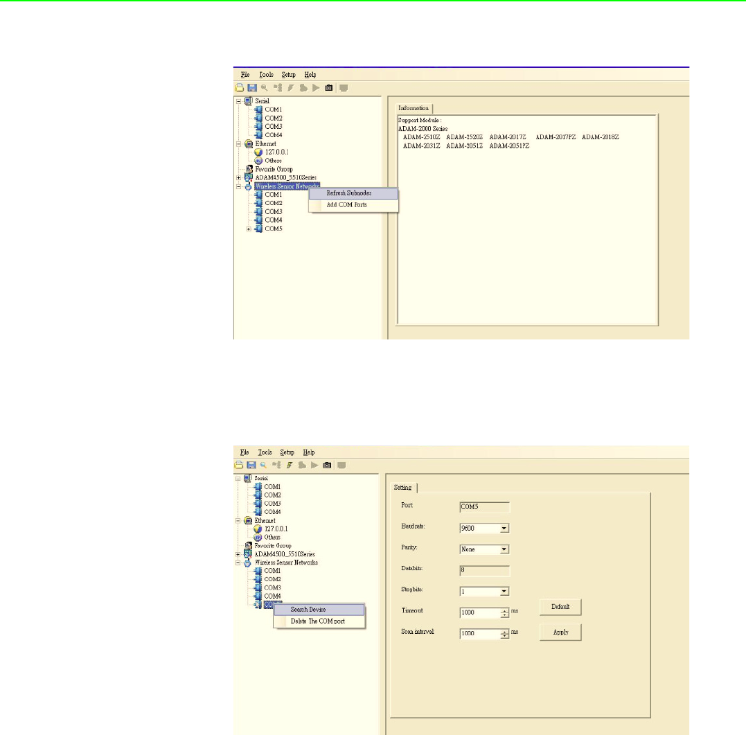
ADAM-2000 Series User Manual 52
Click the “Serial” in the Wireless Sensor Networks category then click right button to
select the “Refresh Subnode” to search the virtual COM port on the host PC.
Figure 5.4 Search the USB interface ADAM-2000 devices on the host PC for the
virtual COM port.
Click the COM port then click right button to select the "Search" to find the ADAM-
2000 devices.
Figure 5.5 Search the COM port for the ADAM-2000 devices.
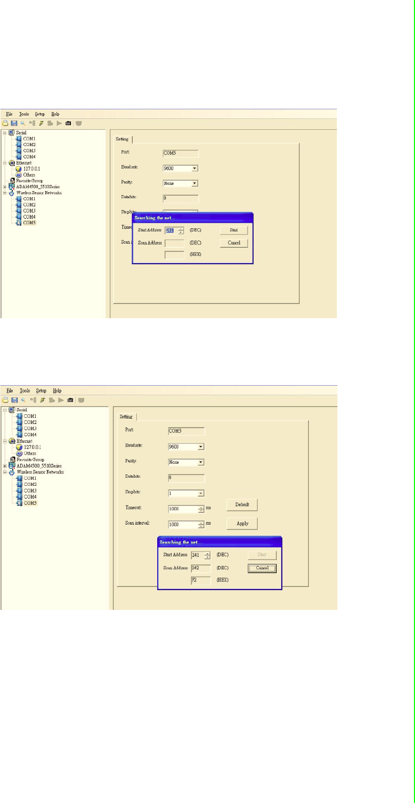
53 ADAM-2000 Series User Manual
Chapter 5 Software Configuration Guide
The “Searching the network” dialog will pop up, click “Start” to search the ADAM-
2000 devices. The AdamApax .NET Utility search the ADAM-2000 Coordinators from
Initial mode Modbus ID 241(F1h)-244(F4h) [for Normal mode Modbus ID 245(F5h)-
249(F5h)], refer to Appendix A.2 for more information.
Figure 5.6 Searching the network dialog
The ADAM-2000 coordinators will be listed on the Tree View of the selected COM
port.
Figure 5.7 Searching the ADAM-2000 coordinators.
If you also want to connect ADAM-2000 series to utility at the same time,
1. Make sure they are in initial mode
2. Set PAN ID in the same group
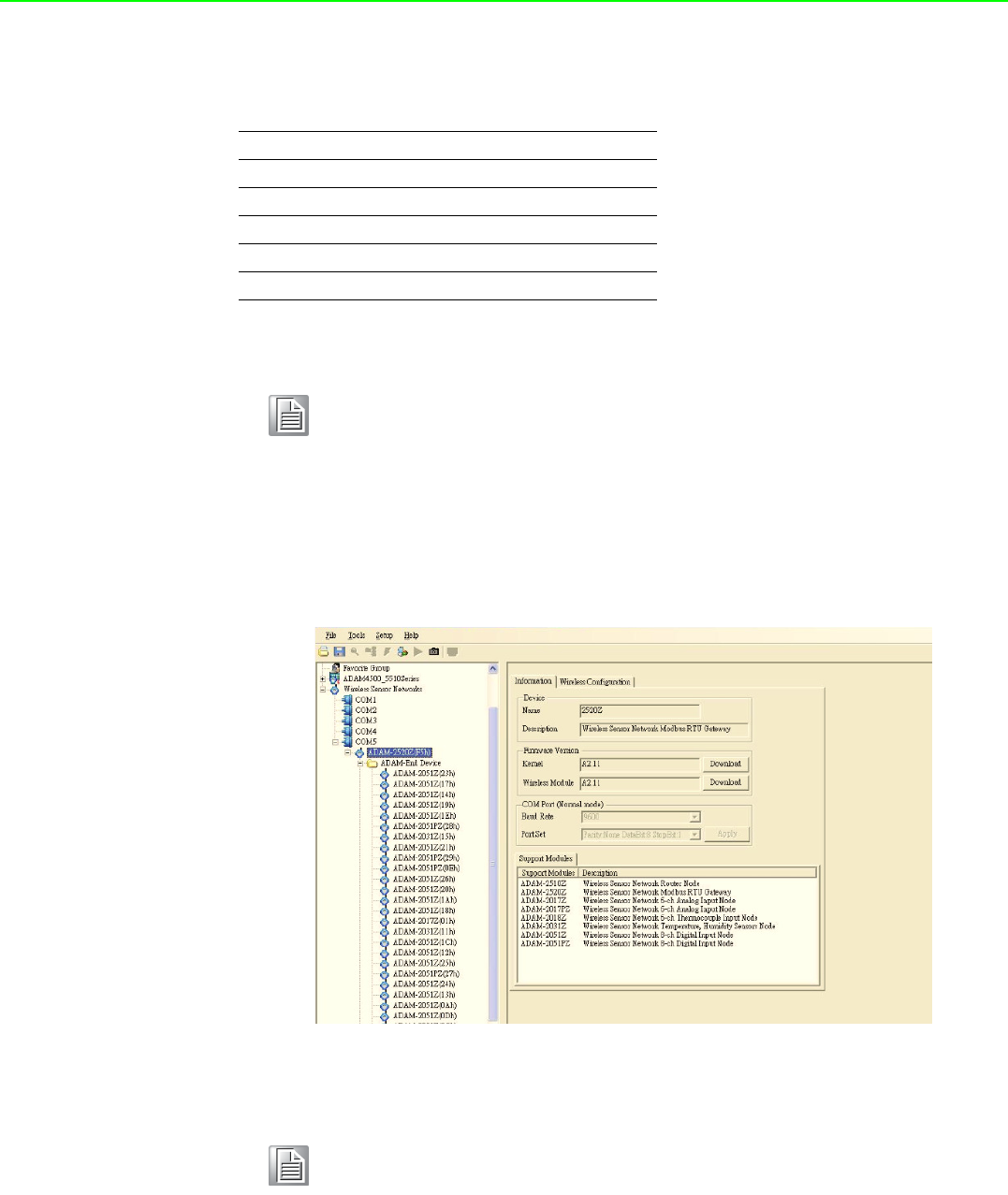
ADAM-2000 Series User Manual 54
Bellow picture is router or end-device signal label for you reference, it also list on
ADAM-2000 series part.
While the searching is done, the ADAM-2000 devices will be listed on the Tree View
with information and parameter pages. The ADAM-Router folder lists routers under
the coordinator (Gateway). The ADAM-End Device folder lists end devices also
under the coordinator (Gateway).
Figure 5.8 ADAM-2000 devices lists on the Tree View and Information page.
Press Button Function
2 seconds Reboot / Confirm
1 time Link Quality Indicator
2 times Battery Level
3 times Associate
5 times Pair ID
Note! ADAM-2520Z each time you turn to initial mode, beware its Pair ID
would be changed because system will depend on your wireless envi-
ronment to get Pair ID to avoid ID conflict. So must make sure your
device using same Pair ID and in same group.
Note! When End Device and Router are set in same slave ID that modules
tree view will be highlighted in yellow.
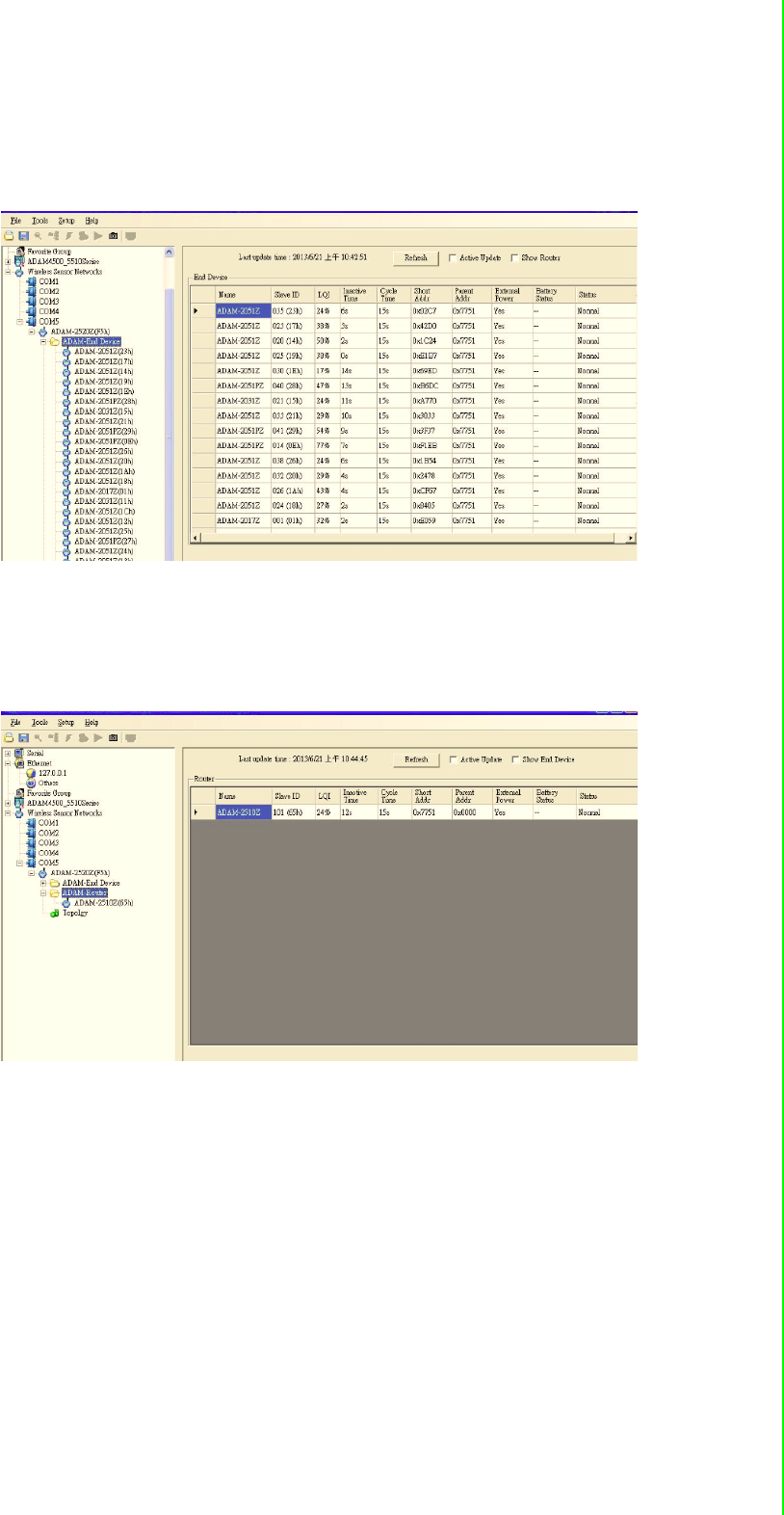
55 ADAM-2000 Series User Manual
Chapter 5 Software Configuration Guide
Folder of ADAM-End Device lists the ADAM-2000 end devices in Tree View and List
View of End Device page. The page contains an overview of the end devices and the
status.
Figure 5.9 The overview of ADAM-2000 end devices.
Folder of ADAM-Router lists the ADAM-2000 routers in Tree View and List View of
Router page. The page contains an overview of the routers and the status.
Figure 5.10 The overview of ADAM-2000 routers
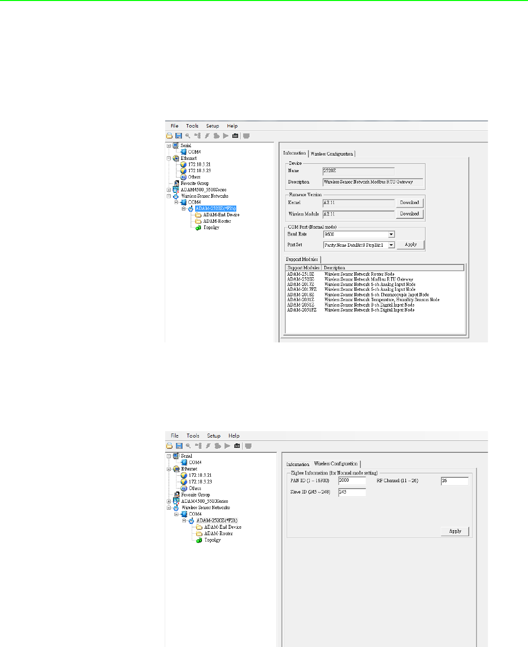
ADAM-2000 Series User Manual 56
5.3.2.1 Gateway - ADAM-2520Z
Click the ADAM-2520Z, it will display the Information and Wireless Configuration
pages.
In the Information page:
1. User can download the firmware to the ADAM-2520Z if there is any upgrade
firmware from the Advantech.
2. User can modify the COM port parameters for Normal Mode.
Figure 5.11 Information page of ADAM-2520Z
Select the "Wireless Configuration" page.
1. Set PAN ID and RF Channel to host a PAN for wireless communication in Nor-
mal Mode.
2. Set Slave ID for Modbus communication in Normal Mode.
Figure 5.12 Wireless Configuration page of the ADAM-2520Z.
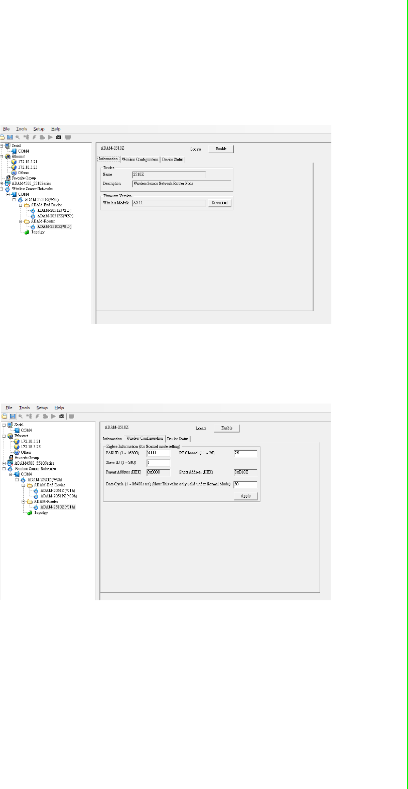
57 ADAM-2000 Series User Manual
Chapter 5 Software Configuration Guide
5.3.2.2 Router - ADAM-2510Z
Click the ADAM-2510Z, it will display the Information, Wireless Configurations and
Device Status. In the Information page, users can download the firmware to the
ADAM-2510Z if there is any upgrade firmware from the Advantech.
Figure 5.13 Information page of ADAM-2510Z
In the Wireless Configuration page, set PAN ID and RF Channel to host a PAN for
wireless communication in Normal Mode.
Figure 5.14 Wireless Configuration page of ADAM-2510Z
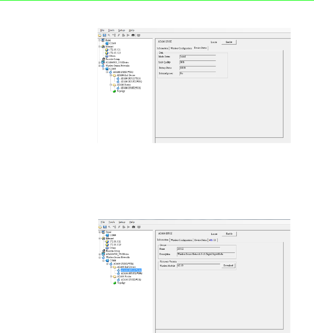
ADAM-2000 Series User Manual 58
In the Device Status page, user can check the Module Status, Link Quality, Battery
Status and External Power of a device.
Figure 5.15 The Device Status page of the ADAM-2510Z
5.3.2.3 End Device - ADAM-2017PZ, ADAM-2031Z, ADAM-2051Z,
ADAM-2051PZ
Click the ADAM End device icon, it will display the Information and Wireless
Configuration pages in Status Display area. In the Information page, user can
download the firmware to the ADAM End device if have any upgrade firmware from
Advantech.
Figure 5.16 Information Page
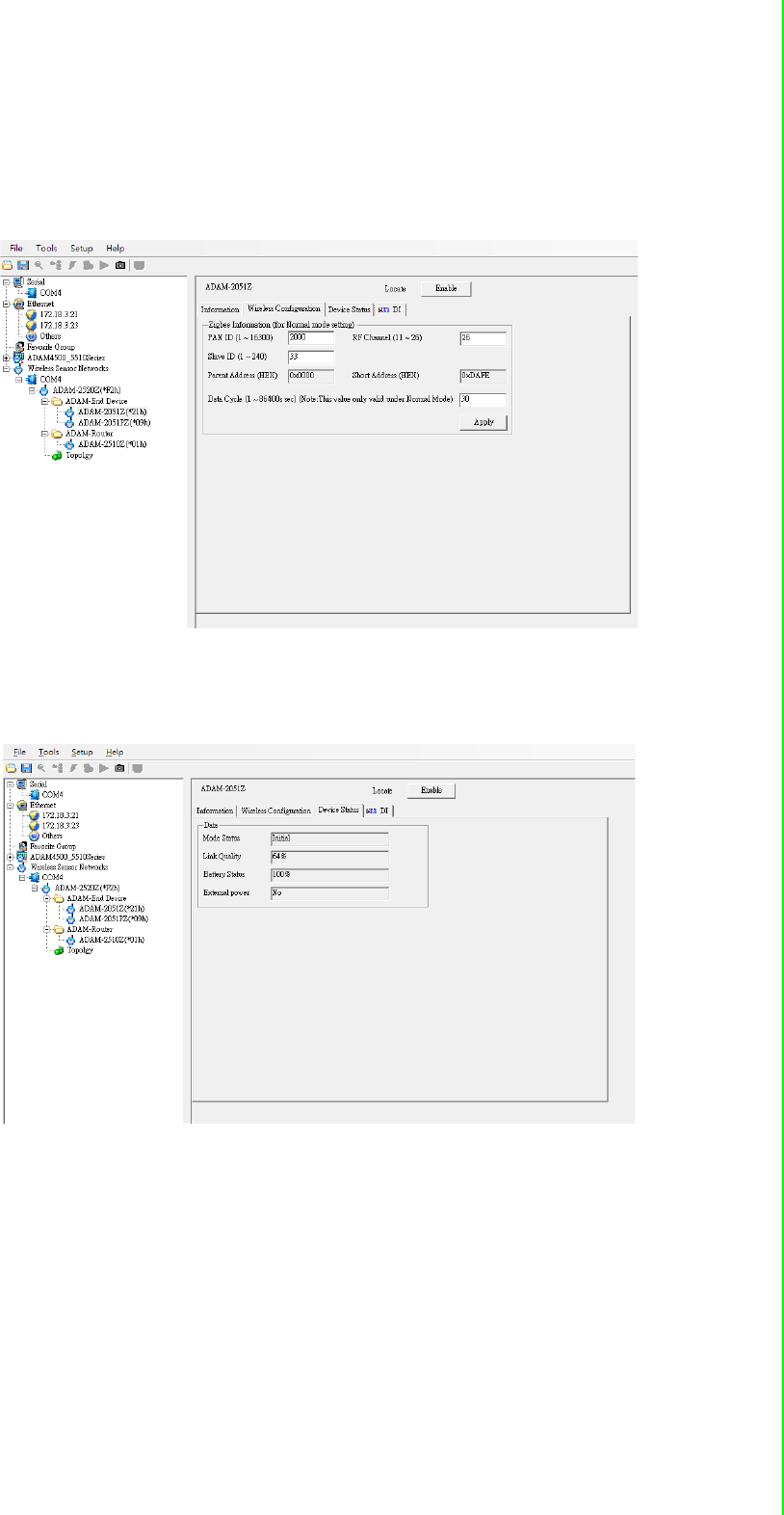
59 ADAM-2000 Series User Manual
Chapter 5 Software Configuration Guide
In the “Wireless Configuration page”:
1. Set PAN ID and RF Channel to host a PAN for wireless communication in Nor-
mal Mode.
2. The Duty Cycle is the transmit interval of the device, the device can update the
data by 1 second to 1 day.
Figure 5.17 Wireless Configuration page
In the Device Status page, user can check the Module Status, Link Quality, Battery
Status and External Power of a device.
Figure 5.18 The Device Status page
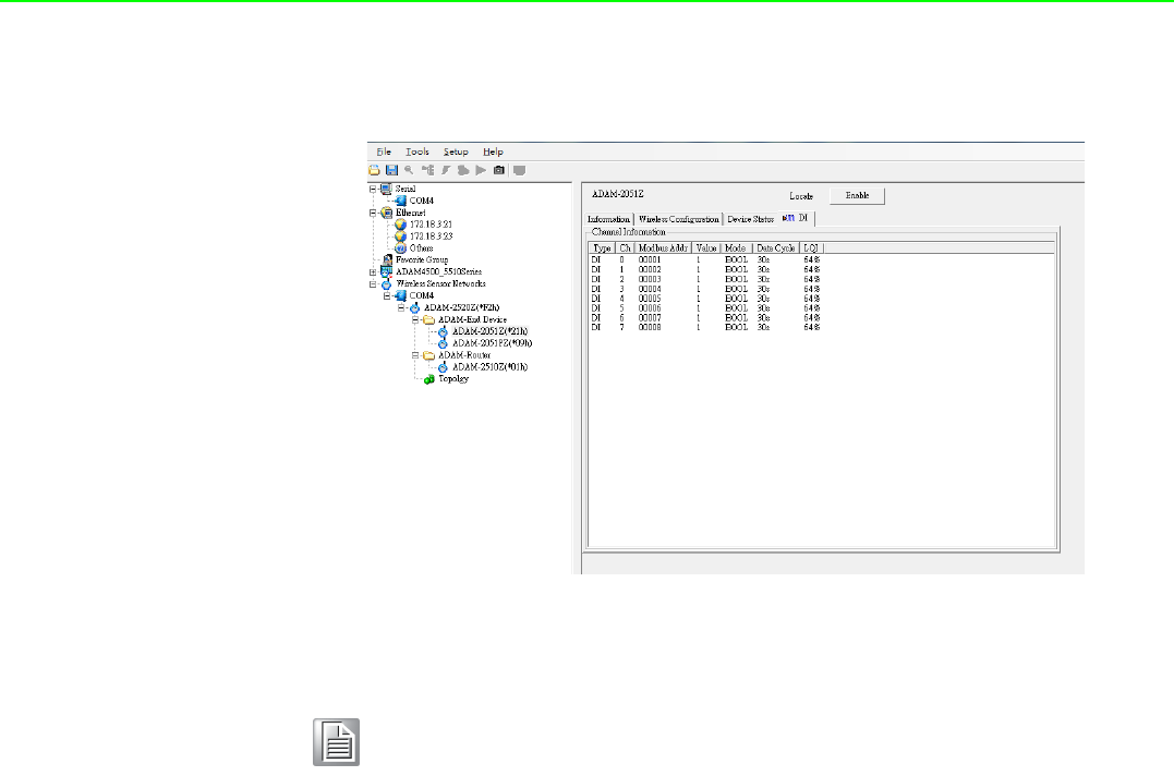
ADAM-2000 Series User Manual 60
In the Signal page, user can check the physical value and Modbus address of the
device by related channel or sensor.
Figure 5.19 The Signal page
Note! During the process of device firmware update, the data of firmware will
be transferred from the coordinator to the end devices through the wire-
less communication. Due to the environment limitation or the interfer-
ence from other wireless equipment, the complete time of firmware
update is dependent on the wireless environment in the real site. Under
the non-interference environment and good level of LQI signal, firmware
update for an end device would normally be completed in 3 minutes.
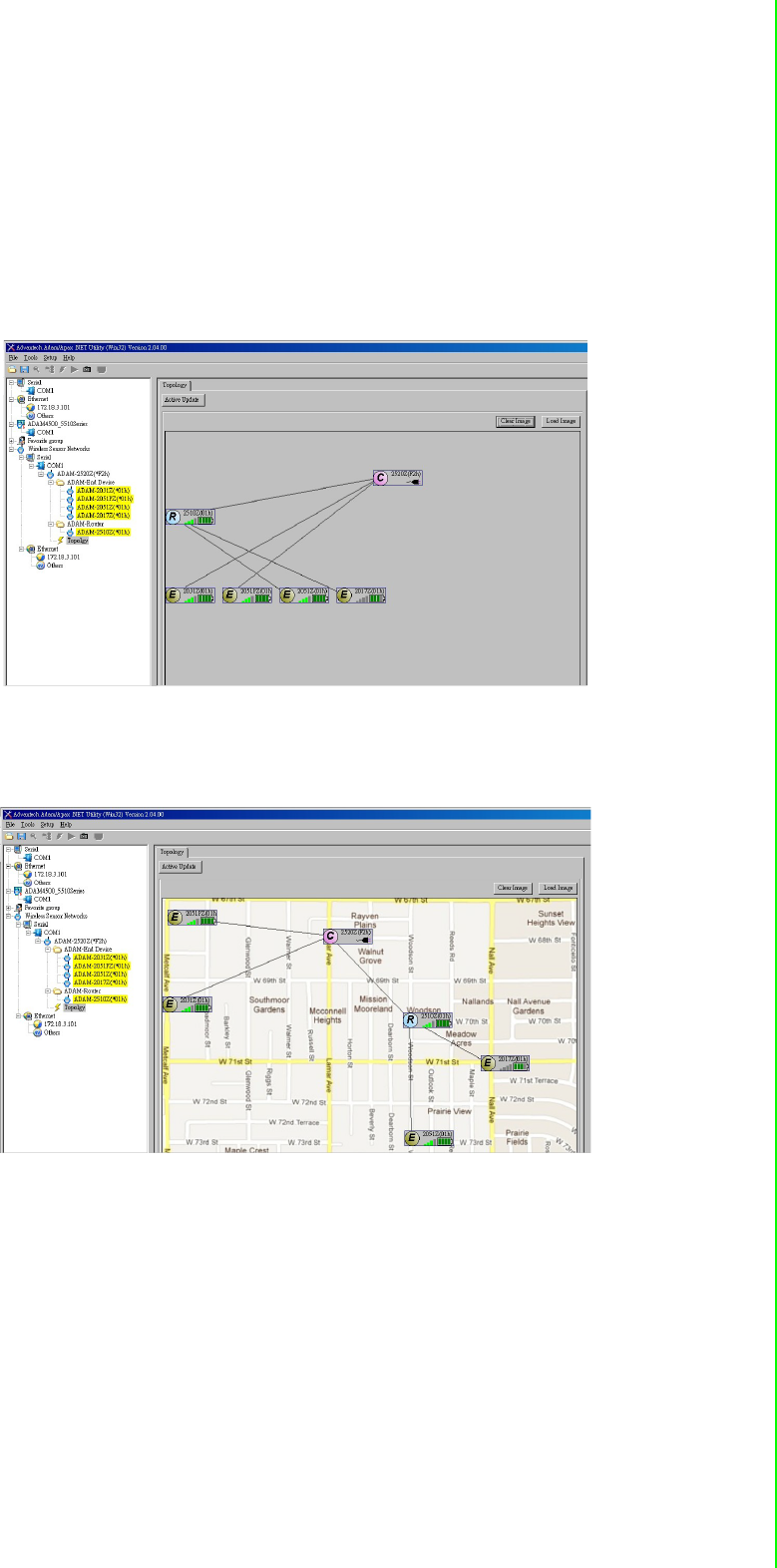
61 ADAM-2000 Series User Manual
Chapter 5 Software Configuration Guide
5.3.3 Network Topology of ADAM-2000 Series
After the ADAM-2000 devices have been discovered, all the devices will be listed on
the Tree View and the Topology also lists the relations between devices in advance.
Click the Topology, the relations of ADAM-2000 devices will be illustrated in the
Topology page. There are three components with model name and status listed on
the Topology. The "C" represents the role of Coordinator, the "R" represents the role
of Router and the "E" represents the role of End Device. You can scroll position on
the screen using a mouse.
Figure 5.20 Topology of the ADAM-2000 series
The function allows user to put a picture on the background and drag the compo-
nents to any positions of the background. With the function, user can easily maintain
and check the status of the ADAM-2000 network.
Figure 5.21 Topology of ADAM-2000 network with specific background image
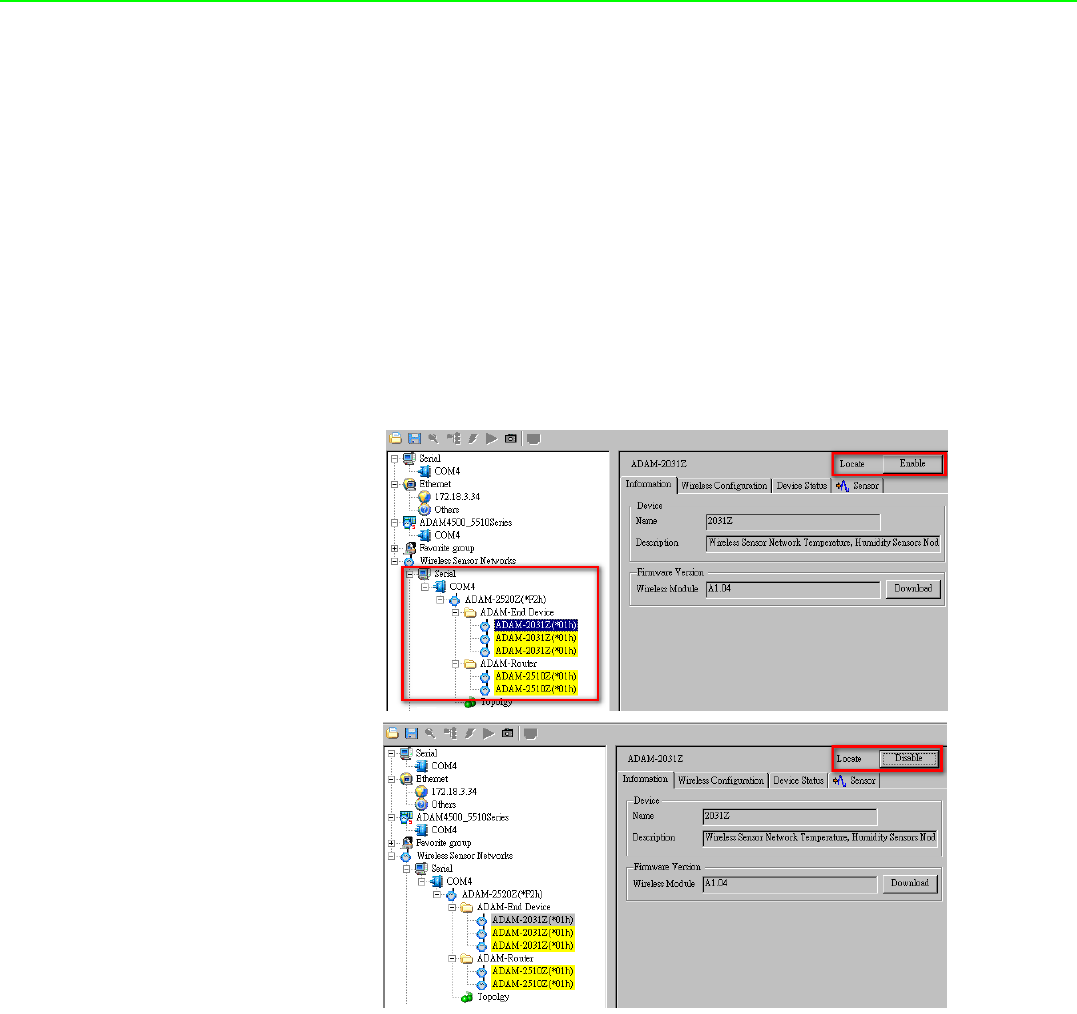
ADAM-2000 Series User Manual 62
5.3.4 Module Locate Function of ADAM-2000 Series (Except ADAM-
2520Z)
Knowing where module positions are located is one of the most important things for
users creating a network topology with a utility. In the initial mode, the AdamApax
.NET utility supports locate function for user to find out where current module posi-
tions are located.
Locate function allows user to locate more than one module at the same time, user
just need to select a module that you want to be located then click “Enable” button in
status display area as Figure 5.22. Located module's LED indicator of Level Index
will keep flashing when it is located, when click “Disable” button that module locate
function will be terminated and LED indicator of Level Index will stop flashing.
Figure 5.22 Node Tree
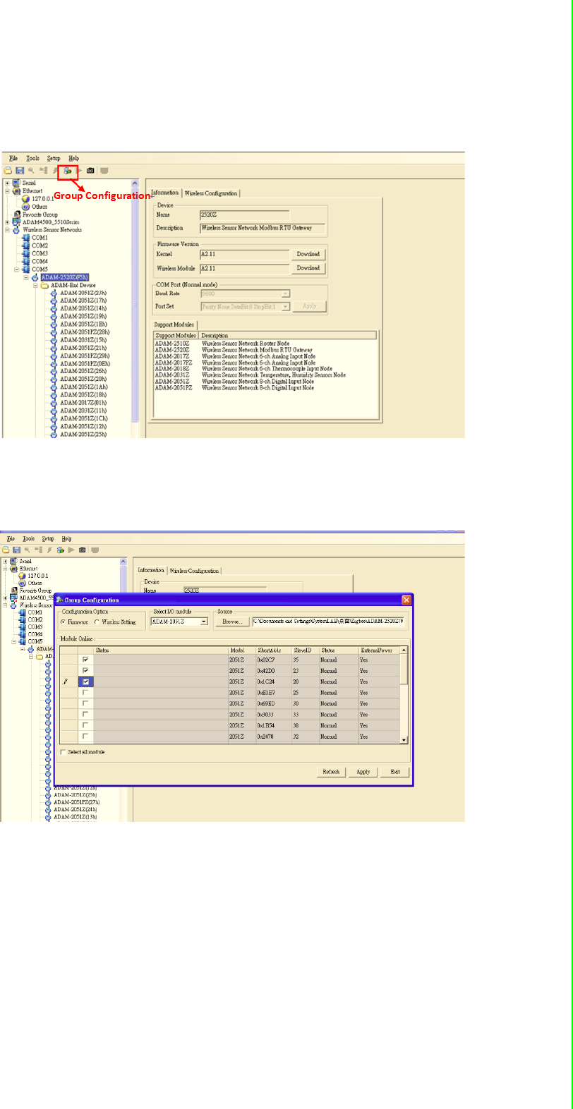
63 ADAM-2000 Series User Manual
Chapter 5 Software Configuration Guide
5.3.5 Group Configuration
The Group Configuration is an efficient function which can support user to configure
multiple end devices.
Figure 5.23 Group Configuration
The firmware configuration option, can perform firmware updates for multiple end
devices which users select. After selecting the types of modules and specifying the
file source, the selected modules would be updated by sequence.
Figure 5.24 Firmware Update in Group Configuration
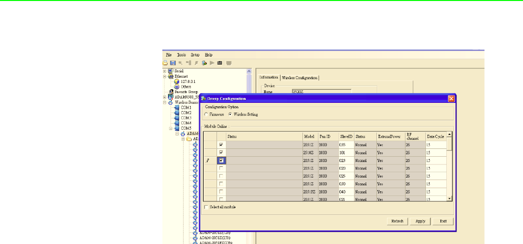
ADAM-2000 Series User Manual 64
The wireless setting option, can set the value of Slave ID and Data Cycle for multiple
modules which users select.
Figure 5.25 Wireless Setting of Group Configuration

Appendix A
AADAM-2000 Series
Functions

ADAM-2000 Series User Manual 66
A.1 Introduction
ADAM-2000 series supports Modbus RTU protocol and serves as Modbus slave
devices that takes commands from a Modbus master. Each module has its own
unique Modbus ID such that master can address each individual slave. The ADAM-
2000 series are the Modbus RTU ready communication solution for Wireless Sensor
Network data acquisition applications.
A.2 ADAM-2000 I/O Modbus Mapping Table
To use the Modbus devices properly, the Modbus ID, Function code, Register
Address and Value must be properly configured. In this section, you can find the
detail Modbus information of the ADAM-2000 series.
Table A.1: Modbus ID Table of ADAM-2000 series
Function Modbus ID Range
Coordinator 241 ~ 244 (Initial Mode), 245 ~ 248(Normal Mode)
Router 1~240
End Device 1~240
Note! * Modbus registers below are based on the firmware version A2.10 B03
and later on.

67 ADAM-2000 Series User Manual
Appendix A ADAM-2000 Series Functions
A.2.1 ADAM-2520Z
Wireless Sensor Network Modbus RTU Gateway
03 Read Holding Registers
Table A.2: ADAM-2520Z Mapping Table
Address 4x Description Attribute Value
40211 Module Name 1 Read 0x2520
40212 Module Name 2 Read 0x5A00 (ASCII Code of 'Z')
40213 Wireless Module
Firmware Version 1 Read Version Number
(ex: 0xA210 means version A2.10)
40214 Wireless Module
Firmware Version 2 Read Build Version Number
(ex: 0x0003 means version B03)
40217 Kernel
Firmware Version 1 Read Version Number
(ex: 0xA210 means version A2.10)
40218 Kernel
Firmware Version 2 Read Build Version Number
(ex: 0x0500 means version B05)
40301 Module Status Read
Bit 0: 0; Initial Mode
Bit 0: 1; Normal Mode
Bit 1: 0; *No External Power Input
Bit 1: 1; External Power Input
40303 Battery Level Read
0x0000; Low
0x4000; Poor
0x8000; Normal
0xC000; Good
0xFFFF; Excellent
40304 Connection failed threshold
(N times of data cycle) Read 0x0002
40305
Disconnection threshold
(N times of connection
failed threshold)
Read 0x0002
40306 Link Status Read
Bit 0: Connected
Bit 1: Link Failure
Bit 2: Disconnected
Bit 3: Connecting
40310 Device Short Address Read 0x0000~0xFFFF
Note! * It should be USB or battery power input. It does not recommend user
to use battery as power source for ADAM-2520Z.

ADAM-2000 Series User Manual 68
A.2.2 ADAM-2510Z
Wireless Sensor Network Router Node
03 Read Holding Registers
Table A.3: ADAM-2510Z Mapping Table
Address 4x Description Attribute Value
40211 Module Name 1 Read 0x2510
40212 Module Name 2 Read 0x5A00 (ASCII Code of 'Z')
40213 Wireless Module
Firmware Version 1 Read Version Number
(ex: 0xA210 means version A2.10)
40214 Wireless Module
Firmware Version 2 Read Build Version Number
(ex: 0x0003 means version B03)
40301 Module Status Read
Bit 0: 0; Initial Mode
Bit 0: 1; Normal Mode
Bit 1: 0; No External Power Input
Bit 1: 1; External Power Input
40302 LQI Read
0x0000~0x00FF
0x0000: No Signal
0x00FF: Excellent
40303 Battery Level Read
0x0000; Low
0x4000; Poor
0x8000; Normal
0xC000; Good
0xFFFF; Excellent
40304 Device Inactive Period
(Upper word) Read
0 ~ 259200 seconds;
Maximum 3 days record
(Total 51840 steps; 5 seconds per step)
40305 Device Inactive Period
(Lower word)
40306 Link Status Read
Bit 0: Connected
Bit 1: Link Failure
Bit 2: Disconnected
Bit 3: Connecting
40307 Data Cycle Time
(Upper) Read 0x00000001~0x00015180
(1 ~ 864000 seconds)
40308 Data Cycle Time
(Lower)
40309 LQI Percentage Read 0x0000~0x0064 (0~100%)
40310 Device Short Address Read 0x0000~0xFFFF
40311 Parent Address Read 0x0000~0xFFFF

69 ADAM-2000 Series User Manual
Appendix A ADAM-2000 Series Functions
A.2.3 ADAM-2017PZ
Wireless Sensor Network 6-ch Analog Input Node
01 Read Coils
03 Read Holding Registers
Table A.4: ADAM-2017PZ Mapping Table
Address Description Attribute Value
00121 AI Ch 0 Burn-Out Flag Read 1: Burn Out
00122 AI Ch 1 Burn-Out Flag Read 1: Burn Out
00123 AI Ch 2 Burn-Out Flag Read 1: Burn Out
00124 AI Ch 3 Burn-Out Flag Read 1: Burn Out
00125 AI Ch 4 Burn-Out Flag Read 1: Burn Out
00126 AI Ch 5 Burn-Out Flag Read 1: Burn Out
40001 AI Value Ch 0 Read 0x0000~0xFFFF; Selected input range
40002 AI Value Ch 1 Read 0x0000~0xFFFF; Selected input range
40003 AI Value Ch 2 Read 0x0000~0xFFFF; Selected input range
40004 AI Value Ch 3 Read 0x0000~0xFFFF; Selected input range
40005 AI Value Ch 4 Read 0x0000~0xFFFF; Selected input range
40006 AI Value Ch 5 Read 0x0000~0xFFFF; Selected input range
40101 AI Status Ch 0 Read *See the table below
40102
40103 AI Status Ch 1 Read *See the table below
40104
40105 AI Status Ch 2 Read *See the table below
40106
40107 AI Status Ch 3 Read *See the table below
40108
40109 AI Status Ch 4 Read *See the table below
40110
40111 AI Status Ch 5 Read *See the table below
40112
40201 AI Type Ch 0 Read *See the table below
40202 AI Type Ch 1 Read *See the table below
40203 AI Type Ch 2 Read *See the table below
40204 AI Type Ch 3 Read *See the table below
40205 AI Type Ch 4 Read *See the table below
40206 AI Type Ch 5 Read *See the table below
40211 Module Name 1 Read 0x2017
40212 Module Name 2 Read 0x5A00 (ASCII Code of 'Z')
40213 Wireless Module
Firmware Version 1 Read Version Number
(ex: 0xA210 means version A2.10)
40214 Wireless Module
Firmware Version 2 Read Build Version Number
(ex: 0x0003 means version B03)
40301 Module Status Read
Bit 0: 0; Initial Mode
Bit 0: 1; Normal Mode
Bit 1: 0; No External Power Input
Bit 1: 1; External Power Input

ADAM-2000 Series User Manual 70
40302 LQI Read
0x0000~0x00FF
0x0000: No Signal
0x00FF: Excellent
40303 Battery Level Read
0x0000; Low
0x4000; Poor
0x8000; Normal
0xC000; Good
0xFFFF; Excellent
40304 Device Inactive Period
(Upper word) Read
0 ~ 259200 seconds;
Maximum 3 days record
(Total 51840 steps; 5 seconds per step)
40305 Device Inactive Period
(Lower word)
40306 Link Status Read
Bit 0: Connected
Bit 1: Link Failure
Bit 2: Disconnected
Bit 3: Connecting
40307 Data Cycle Time
(Upper word) Read 0x00000001~0x00015180
(1 ~ 864000 seconds)
40308 Data Cycle Time
(Lower word)
40309 LQI Percentage Read 0x0000~0x0064 (0~100%)
40310 Device Short Address Read 0x0000~0xFFFF
40311 Parent Address Read 0x0000~0xFFFF
Table A.4: ADAM-2017PZ Mapping Table

71 ADAM-2000 Series User Manual
Appendix A ADAM-2000 Series Functions
*ADAM-2017PZ AI Type Code (Range Code)
Input Range Value
+/- 10V 0x0143
+/- 5 V 0x0142
+/- 1 V 0x0140
+/- 500 mV 0x0104
+/- 150 mV 0x0103
+/- 20 mA 0x0181
0 ~ 20 mA 0x0182
4 ~ 20 mA 0x0180
*ADAM-2017PZ AI Status (1st Register at Low Address)
Status Description Bit Order
A/D Convert Timeout (Fail) 0
Over Range 1
Under Range 2
Open Circuit (Burn-Out) 3
Reserved 4
Not Converted Yet 5
Reserved 6
ADC Initializing Error 7
Reserved 8
Zero Span Calibration Error 9
Reserved 10 ~ 15
*ADAM-2017PZ AI Status (2nd Register at Low Address)
Status Description Bit Order
Reserved 0 ~ 15

ADAM-2000 Series User Manual 72
A.2.4 ADAM-2031Z
Wireless Sensor Network Temperature and Humidity Sensors Node
03 Read Holding Registers
Table A.5: ADAM-2031Z Mapping Table
Address 4X Description Attribute Value
40001 Temperature Input Read 0x0000 ~ 0xFFFF*
40002 Humidity Input Read 0x0000 ~ 0xFFFF**
40211 Module Name 1 Read 0x2031
40212 Module Name 2 Read 0x5A00 (ASCII Code of 'Z')
40213 Wireless Module
Firmware Version 1 Read Version Number
(ex: 0xA210 means version A2.10)
40214 Wireless Module
Firmware Version 2 Read Build Version Number
(ex: 0x0003 means version B03)
40301 Module Status Read
Bit 0: 0; Initial Mode
Bit 0: 1; Normal Mode
Bit 1: 0; No External Power Input
Bit 1: 1; External Power Input
40302 LQI Read
0x0000~0x00FF;
0x0000: No Signal
0x00FF: Excellent
40303 Battery Level Read
0x0000; Low
0x4000; Poor
0x8000; Normal
0xC000; Good
0xFFFF; Excellent
40304 Device Inactive Period
(Upper word) Read
0 ~ 259200 seconds;
Maximum 3 days record
(Total 51840 steps; 5 seconds per step)
40305 Device Inactive Period
(Lower word)
40306 Link Status Read
Bit 0: Connected
Bit 1: Link Failure
Bit 2: Disconnected
Bit 3: Connecting
40307 Data Cycle Time
(Upper) Read 0x00000001~0x00015180
(1 ~ 864000 seconds)
40308 Data Cycle Time
(Lower)
40309 LQI Percentage Read 0x0000~0x0064 (0~100%)
40310 Device Short Address Read 0x0000~0xFFFF
40311 Parent Address Read 0x0000~0xFFFF
Note! * The temperature T is calculated by inserting temperature signal output
ST into the following formula (result is in oC).
T46.85–175.72x
ST
216
-------
+=

73 ADAM-2000 Series User Manual
Appendix A ADAM-2000 Series Functions
Note! ** The humidity RH is calculated by inserting humidity signal output
SRH into the following formula (result is in %RH)
RH 6– 125x
SRH
216
---------
+=

ADAM-2000 Series User Manual 74
A.2.5 ADAM-2051Z
Wireless Sensor Network 8-ch Digital Input Node
01 Read Coils
03 Read Holding Registers
Table A.6: ADAM-2051Z Mapping Table
Address Description Attribute Value
00001 DI 0 Read Digital Input Value
00002 DI 1 Read Digital Input Value
00003 DI 2 Read Digital Input Value
00004 DI 3 Read Digital Input Value
00005 DI 4 Read Digital Input Value
00006 DI 5 Read Digital Input Value
00007 DI 6 Read Digital Input Value
00008 DI 7 Read N/A
40001 The Value for All DI Read Bit 0 ~ 7 of reading value represent
DI 0 ~ 7
40211 Module Name 1 Read 0x2051
40212 Module Name 2 Read 0x5A00 (ASCII Code of 'Z')
40213 Wireless Module
Firmware Version 1 Read Version Number
(ex: 0xA210 means version A2.10)
40214 Wireless Module
Firmware Version 2 Read Build Version Number
(ex: 0x0003 means version B03)
40301 Module Status Read
Bit 0: 0; Initial Mode
Bit 0: 1; Normal Mode
Bit 1: 0; No External Power Input
Bit 1: 1; External Power Input
40302 LQI Read
0x0000~0x00FF;
0x0000: No Signal
0x00FF: Excellent
40303 Battery Level Read
0x0000; Low
0x4000; Poor
0x8000; Normal
0xC000; Good
0xFFFF; Excellent
40304 Device Inactive Period
(Upper word) Read
0 ~ 259200 seconds;
Maximum 3 days record
(Total 51840 steps; 5 seconds per step)
40305 Device Inactive Period
(Lower word)
40306 Link Status Read
Bit 0: Connected
Bit 1: Link Failure
Bit 2: Disconnected
Bit 3: Connecting
40307 Data Cycle Time
(Upper) Read 0x00000001~0x00015180
(1 ~ 864000 seconds)
40308 Data Cycle Time
(Lower)
40309 LQI Percentage Read 0x0000~0x0064 (0~100%)
40310 Device Short Address Read 0x0000~0xFFFF
40311 Parent Address Read 0x0000~0xFFFF

75 ADAM-2000 Series User Manual
Appendix A ADAM-2000 Series Functions
A.2.6 ADAM-2051PZ
Wireless Sensor Network 8-ch Digital Input Node with Power Amplifier
01 Read Coils
03 Read Holding Registers
Table A.7: ADAM-2051PZ Mapping Table
Address Description Attribute Value
00001 DI 0 Read Digital Input Value
00002 DI 1 Read Digital Input Value
00003 DI 2 Read Digital Input Value
00004 DI 3 Read Digital Input Value
00005 DI 4 Read Digital Input Value
00006 DI 5 Read Digital Input Value
00007 DI 6 Read Digital Input Value
00008 DI 7 Read Digital Input Value
40001 The Value for All DI Read Bit 0 ~ 7 of reading value represent
DI 0 ~ 7
40211 Module Name 1 Read 0x2051
40212 Module Name 2 Read 0x505A (PZ)
40213 Wireless Module
Firmware Version 1 Read Version Number
(ex: 0xA210 means version A2.10)
40214 Wireless Module
Firmware Version 2 Read Build Version Number
(ex: 0x0300 means version B03)
40301 Module Status Read
Bit 0: 0; Initial Mode
Bit 0: 1; Normal Mode
Bit 1: 0; No External Power Input
Bit 1: 1; External Power Input
40302 LQI Read
0x0000~0x00FF;
0x0000: No Signal
0x00FF: Excellent
40303 Battery Level Read
0x0000; Low
0x4000; Poor
0x8000; Normal
0xC000; Good
0xFFFF; Excellent
40304 Device Inactive Period
(Upper word) Read
0 ~ 259200 seconds;
Maximum 3 days record
(Total 51840 steps; 5 seconds per step)
40305 Device Inactive Period
(Lower word)
40306 Link Status Read
Bit 0: Connected
Bit 1: Link Failure
Bit 2: Disconnected
Bit 3: Connecting
40307 Data Cycle Time
(Upper) Read 0x00000001~0x00015180
(1 ~ 864000 seconds)
40308 Data Cycle Time
(Lower)
40309 LQI Percentage Read 0x0000~0x0064 (0~100%)
40310 Device Short Address Read 0x0000~0xFFFF
40311 Parent Address Read 0x0000~0xFFFF

ADAM-2000 Series User Manual 76

Appendix B
BTroubleshooting

ADAM-2000 Series User Manual 78
B.1 Troubleshooting
Q1: Why is the Error LED blinking?
A1:
1. The Coordinator is not hosting a PAN yet. The PAN ID and Channel might be
occupied by another Coordinators. Change to different PAN ID and Channel in
initial mode.
2. The Router/End Device is not joining a PAN. Check if there is a coordinator with
specified PAN ID and Channel to join.
3. Battery level is low.
4. Network is associating.
Q2: Why does the amber LED on Coordinator automatically add a count in initial
mode?
A2: The Coordinator will automatically add the Pair ID while there is another Coordi-
nator nearby and can be detected.
Q3: What are the functions of the amber LEDs in Router and End Device?
A3:
1. Press side button 1 time for LQI.
2. Press side button 2 times for battery level.
3. Press side button 3 times for network association
4. Press side button 5 times to change the Pair ID to associate with the specified
Pair ID coordinator.
Q4: Why are all the amber LEDs on coordinator blinking while operating in initial
mode?
A4: Four Pair ID can be selected in initial mode of coordinators. If there are five coor-
dinators set in initial mode at the same time, the last one will blink to indicate there
are no available Pair ID to use.
Q5: Does the ADAM-2520Z support the HW/SW flow control of serial communica-
tion?
A5: The ADAM-2520Z does not support the HW/SW flow control and the user appli-
cation/software must turn off the HW/SW flow control.
Q6: Can I use the rechargeable battery as the ADAM-2000 series power input?
A6: The ADAM-2000 can not use rechargeable batteries. Besides, the battery will not
be charged while using the external power. We suggest using Energizer L91 Ultimate
Lithium AA battery.
Q7. Does the utility support Microsoft Windows 7 32 & 64 bit versions?
A7. Yes, AdamApax .NET Utility can support Microsoft Windows 7 32 & 64 bit ver-
sions from Advantech AdamApax .NET Utility Ver 2.05.02.
Q8. While switching communication interface from RS-485 to USB, it sometimes will
cause USB unworkable.
A8. If this situation occurs, re-plug in the USB cable.

79 ADAM-2000 Series User Manual
Appendix B Troubleshooting
B.2 Notice
1. When there are 4 set of devices being coordinated at the same time, the level
Index light will be lit by turns.
2. Devices in initial mode will in high power consumption status, beware of your
power status when using batteries.
3. When using the AdamApax .NET Utility the initial value of an ADAM-2051Z is 1.
The ADAM-2051Z also supports dry contacts.
4. If customers want to connect an ADAM-2000 model with SCADA software, they
can use AdamApax .NET Utility to get ADAM-2000 system parameters then
SCADA software can connect them according these parameters.
5. ADAM-2000 models do not support the “My Favorite” function in the AdamApax
.NET Utility.
6. When two set of devices are to be coordinated at the same time, the second set
router and end-device connect to first set of devices.
7. When there are 2 sets of devices to coordinate with at the same time, they need
to reset power to re-initial PAN ID if they want to connect to another set.
8. The device must not be co-located or operating in conjunction with any other
antenna or transmitter. The changes or modifications not expressly approved by
the party responsible for compliance could void the user's authority to operate
the equipment.
and perso with
Note! ADAM-2000 models do not currently support Mod-scan. We will support
this feature in the future.
ADAM-2000 models do not currently support OPC sever., We will sup-
port this feature in the future.

www.advantech.com
Please verify specifications before quoting. This guide is intended for reference
purposes only.
All product specifications are subject to change without notice.
No part of this publication may be reproduced in any form or by any means,
electronic, photocopying, recording or otherwise, without prior written permis-
sion of the publisher.
All brand and product names are trademarks or registered trademarks of their
respective companies.
© Advantech Co., Ltd. 2012