Advantech Co WISE4000 IoT Wireless I/O Module User Manual V4 12 EA User Manual
Advantech Co Ltd IoT Wireless I/O Module V4 12 EA User Manual
UserManual.wiki
>
Advantech Co
>
WISE4000 User Manual
>
Users Manual-1
Contents
1.
Users Manual-1
2.
Users Manual-2
Users Manual-1
Navigation menu
Upload a User Manual
Namespaces
Wiki Guide
HTML
PDF
Info
Views
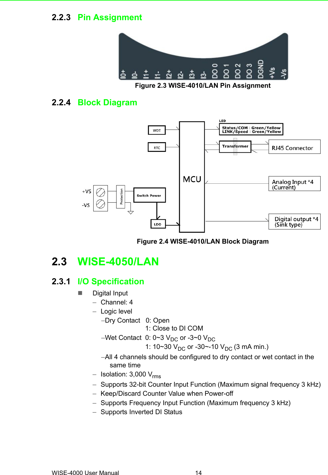
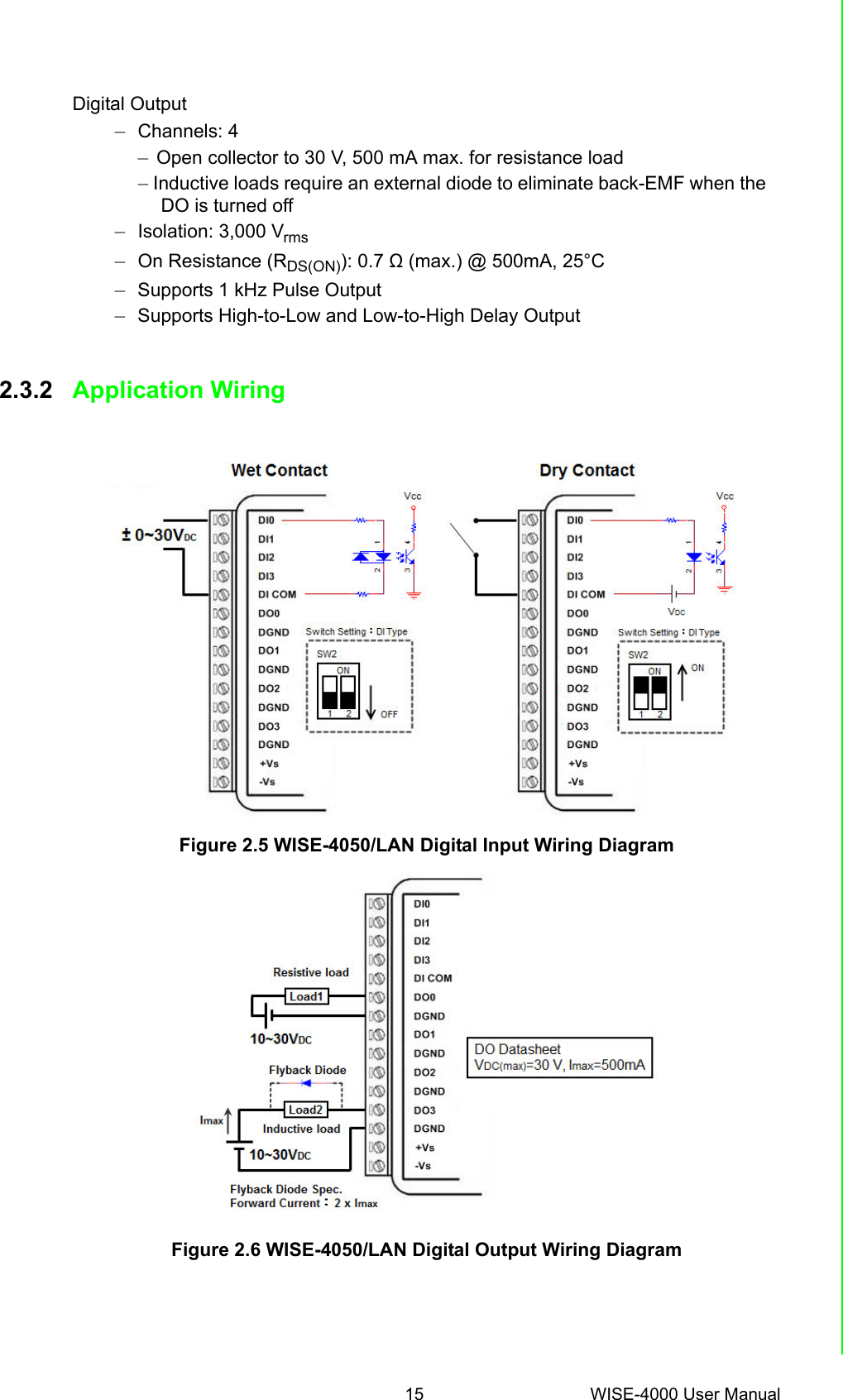
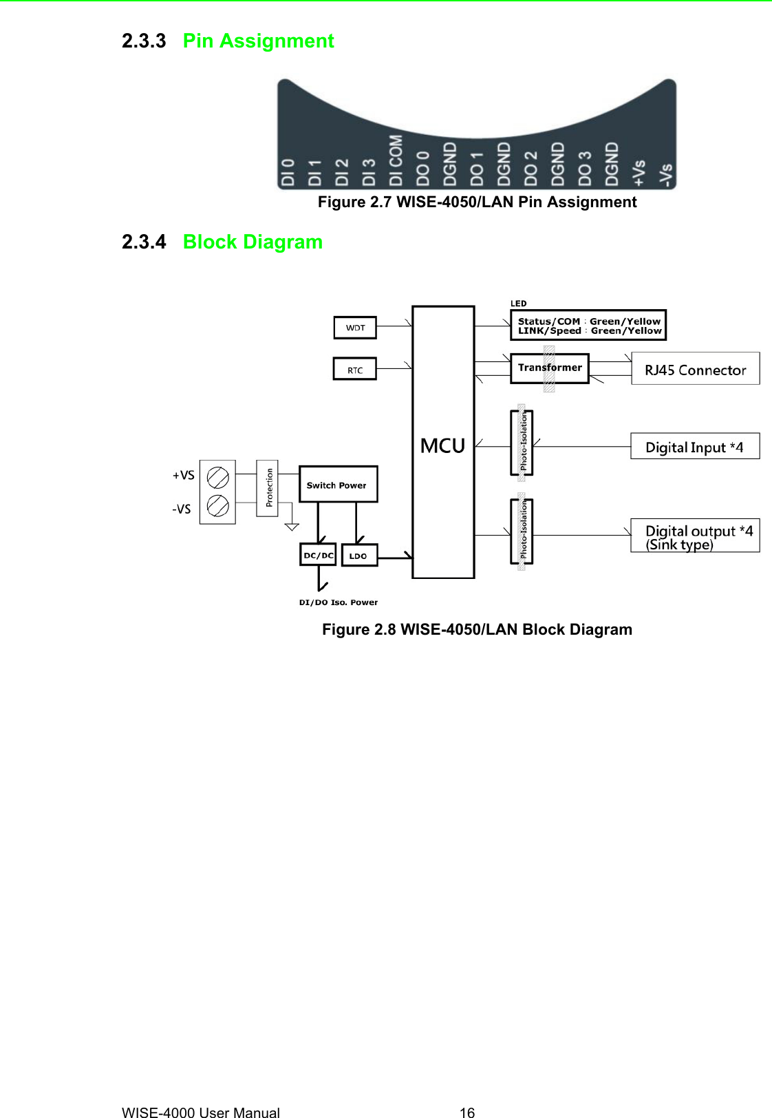
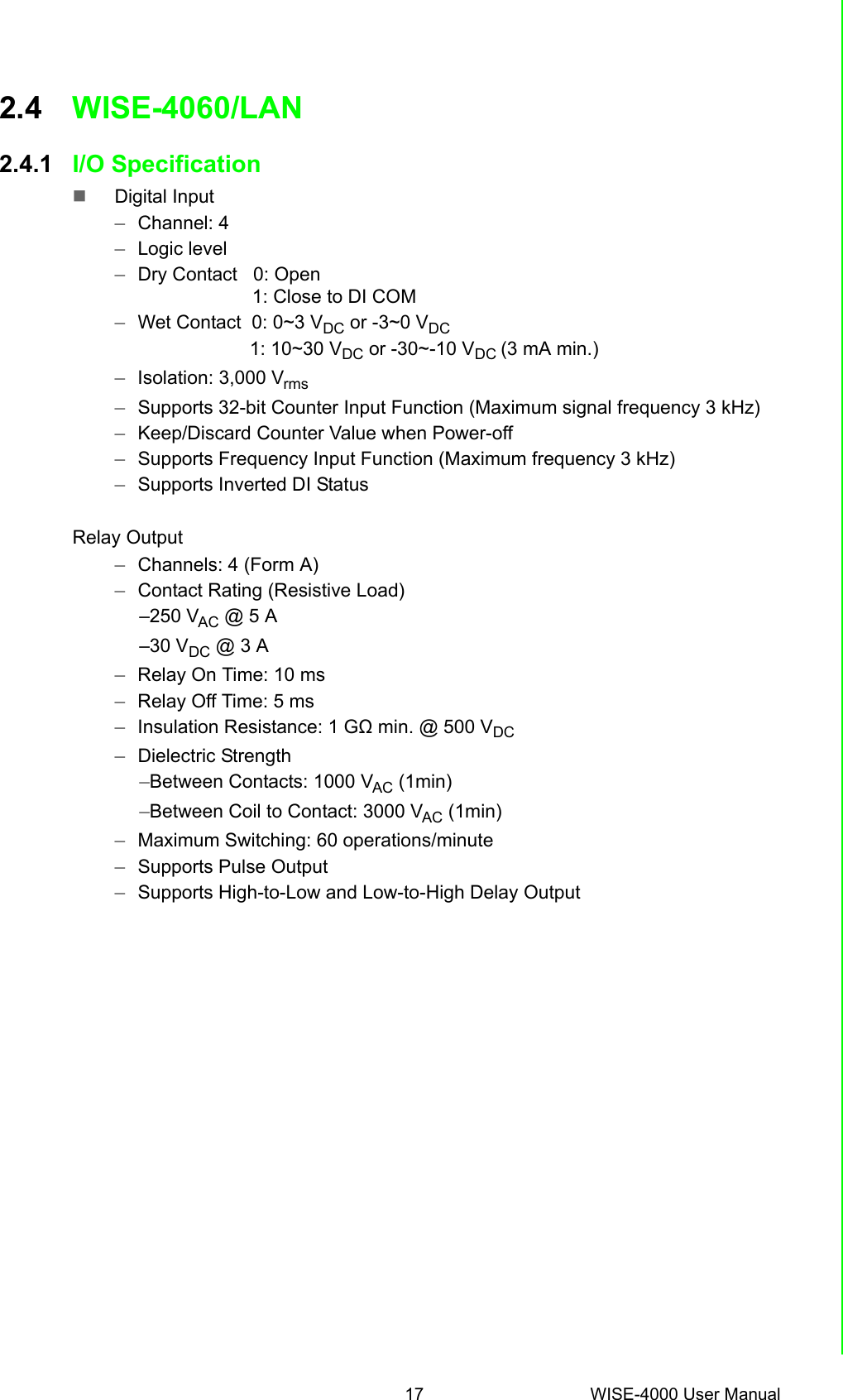
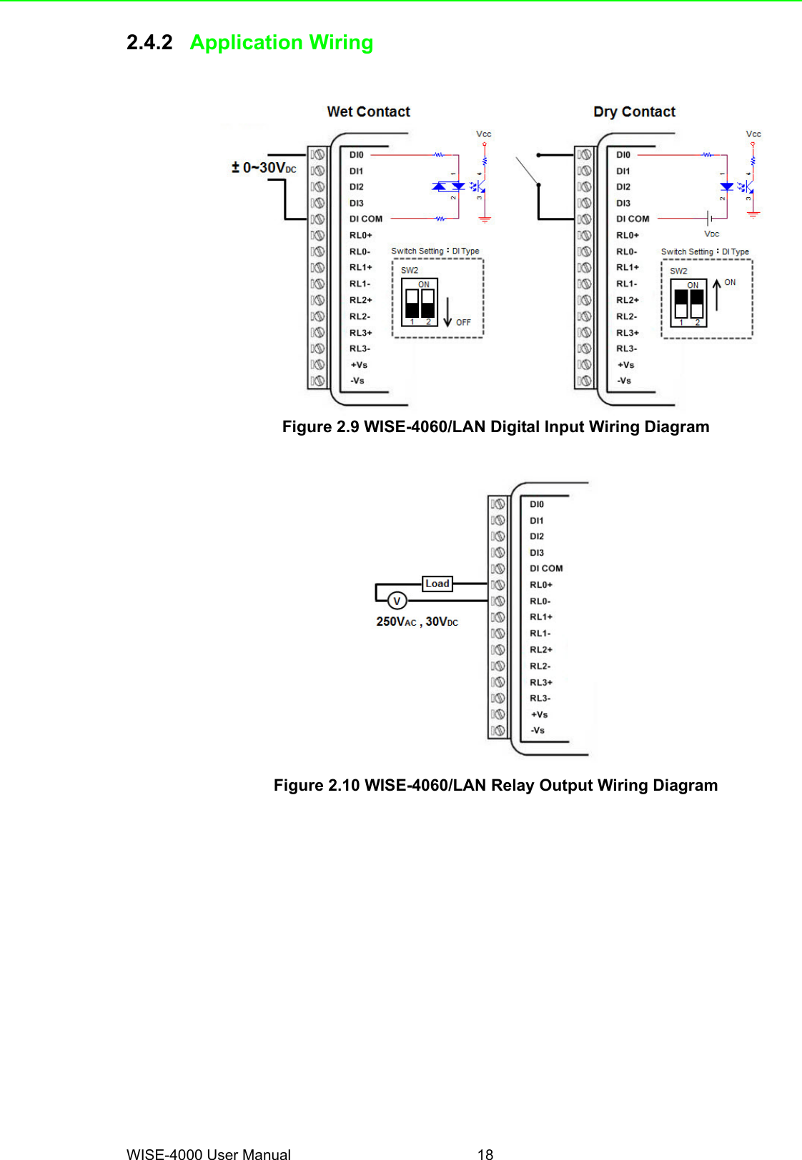
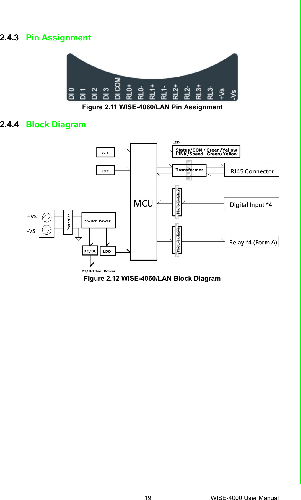
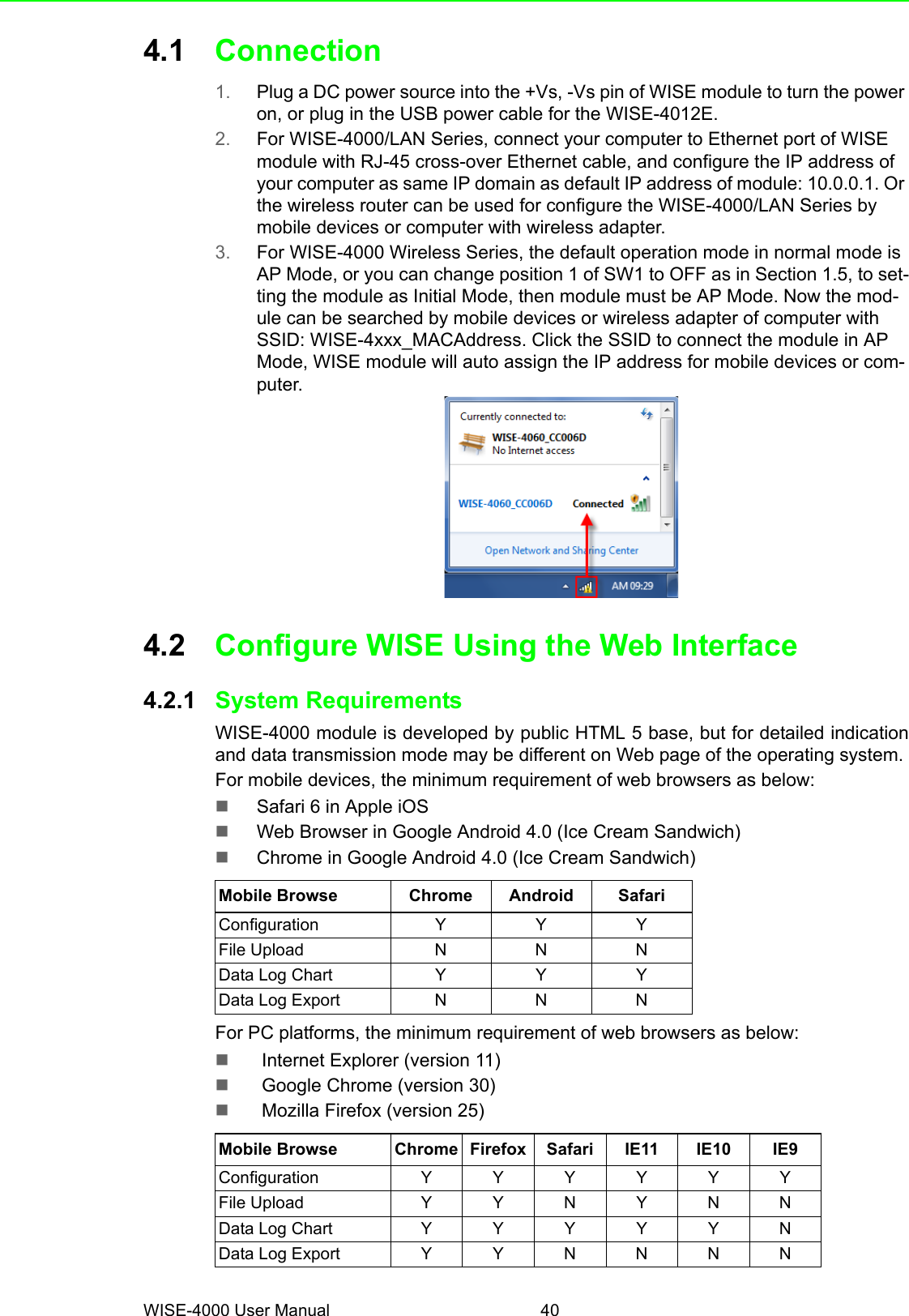
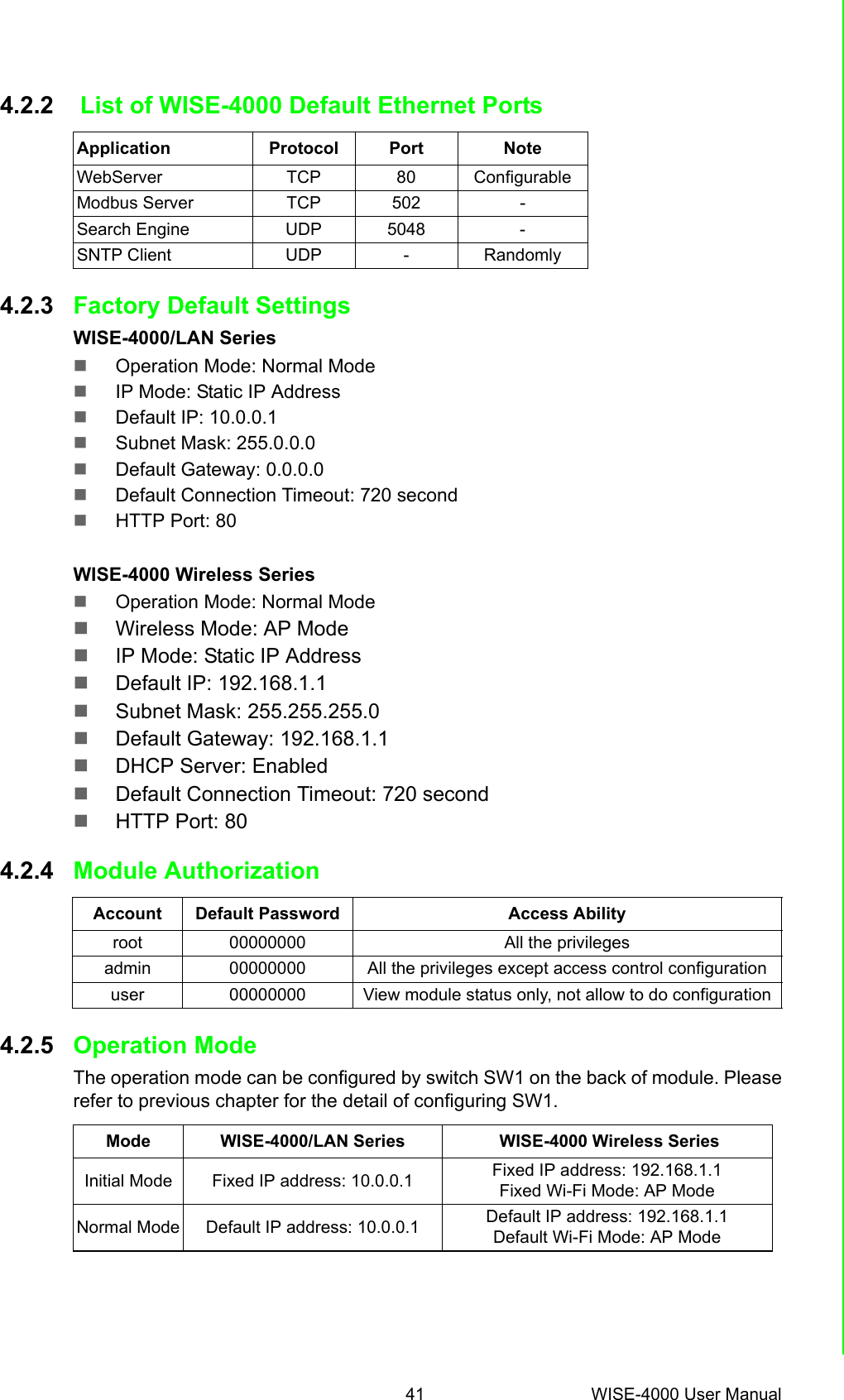
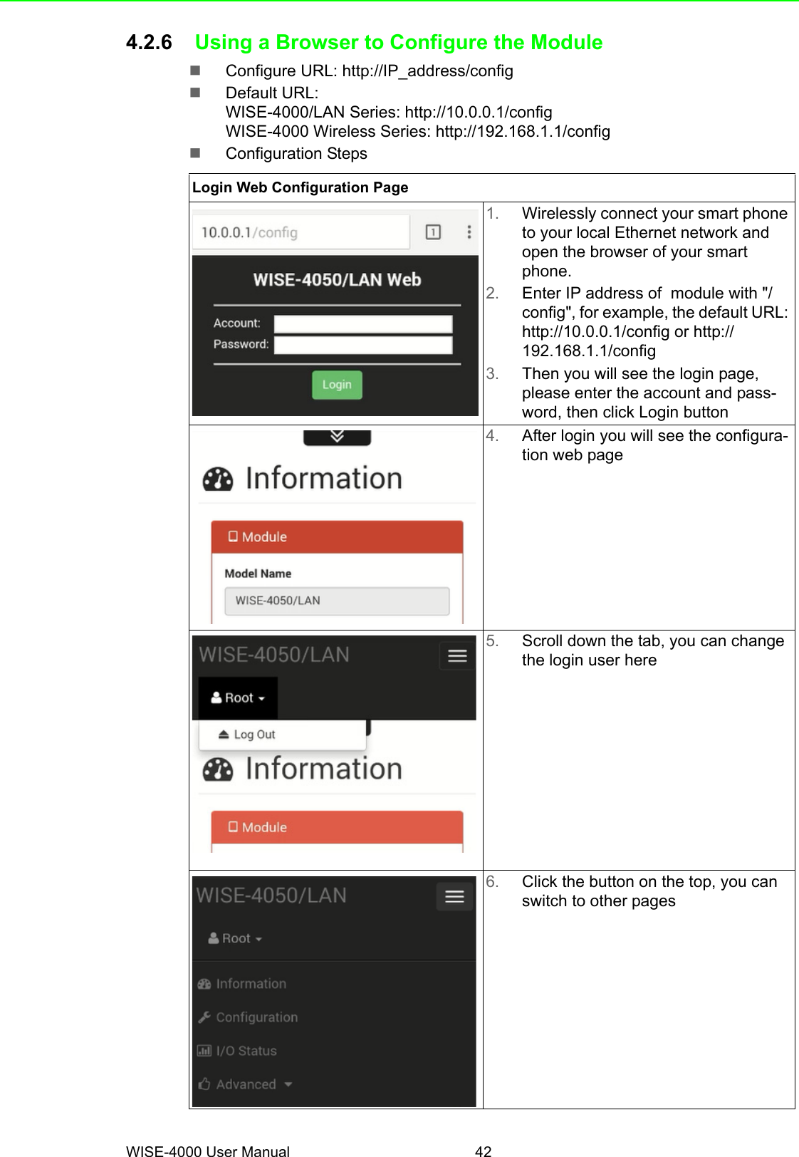
User Manual
Discussion / Help
Navigation