Advantech Co WISE4000 IoT Wireless I/O Module User Manual V4 12 EA User Manual
Advantech Co Ltd IoT Wireless I/O Module V4 12 EA User Manual
UserManual.wiki
>
Advantech Co
>
WISE4000 User Manual
>
Users Manual-2
Contents
1.
Users Manual-1
2.
Users Manual-2
Users Manual-2
Navigation menu
Upload a User Manual
Namespaces
Wiki Guide
HTML
PDF
Info
Views
User Manual
Discussion / Help
Navigation
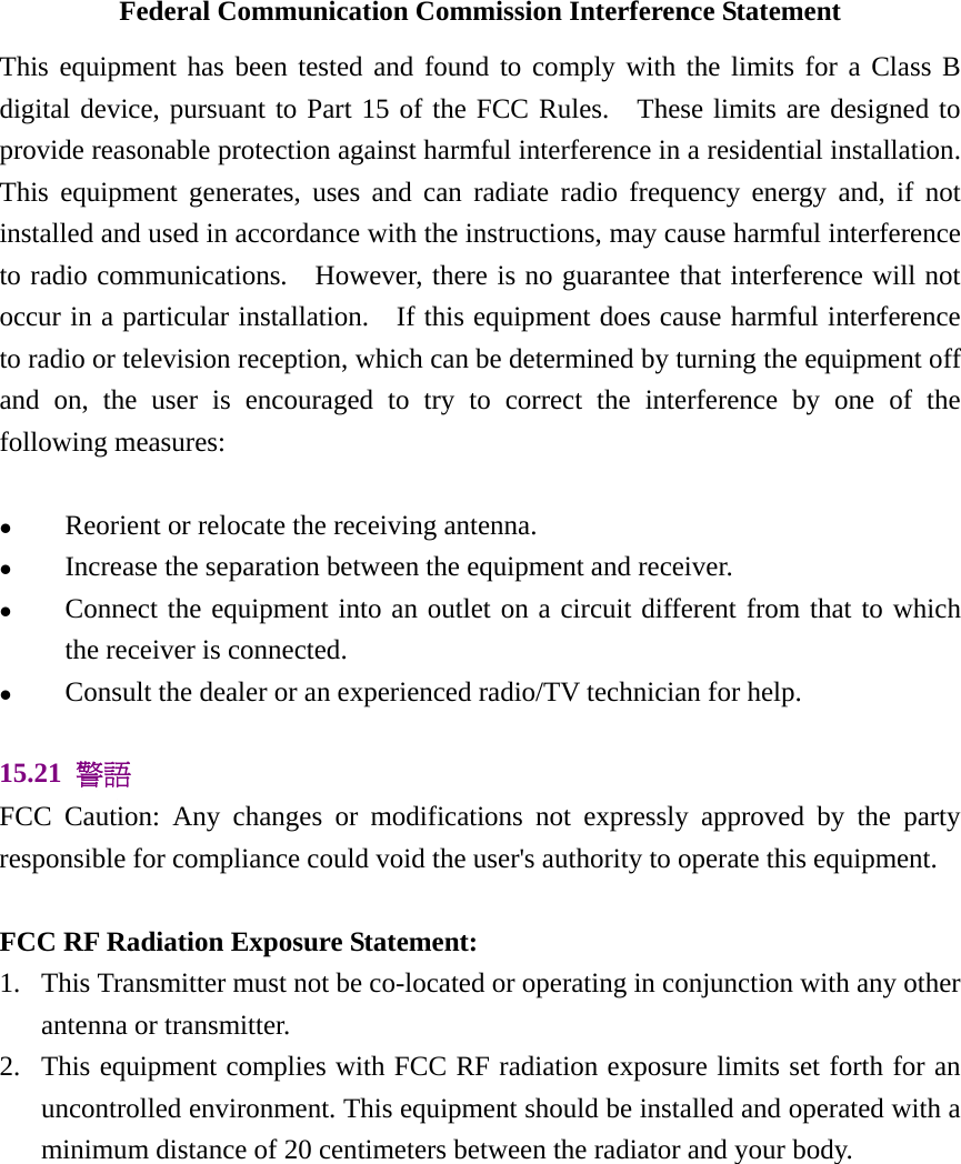
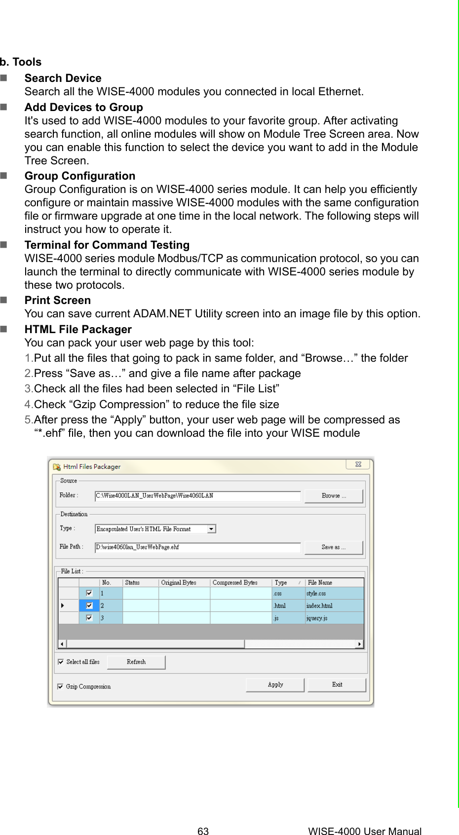
![45 WISE-4000 User ManualChapter 4 System ConfigurationModule Configuration You can click different tab to switch theitem you are going to configure[Information]Customized Name / UUIDMeans model name and UUID of the mod-ule. You also can rename it for recognitionif required.DescriptionYou can add comments on this module forrecognition.Location InformationYou can note the location information forthe module](https://usermanual.wiki/Advantech-Co/WISE4000.Users-Manual-2/User-Guide-2813915-Page-3.png)
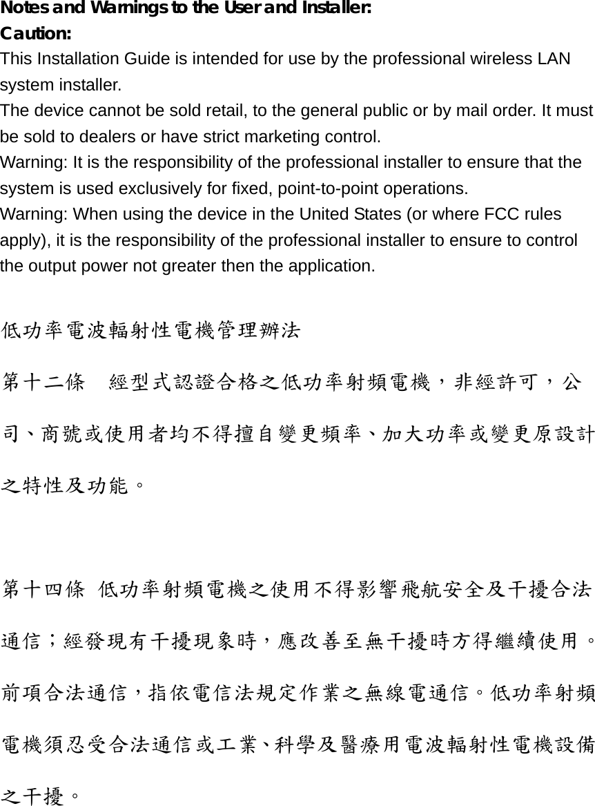
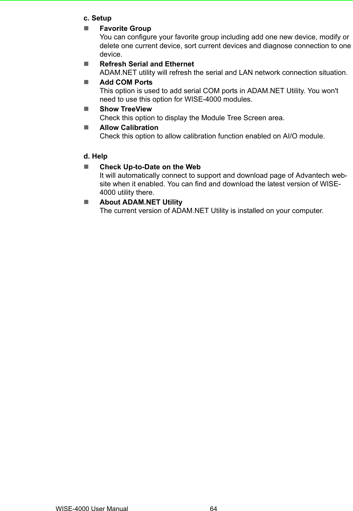
![WISE-4000 User Manual 46Wireless (WISE-4000 Wireless module only) [AP Mode]When using the module in AP mode, userscan configure the SSID and also decidehow the WISE module works as an AP,including the security.The AP-Network is fixed and does notallow user to make their own changes.](https://usermanual.wiki/Advantech-Co/WISE4000.Users-Manual-2/User-Guide-2813915-Page-4.png)
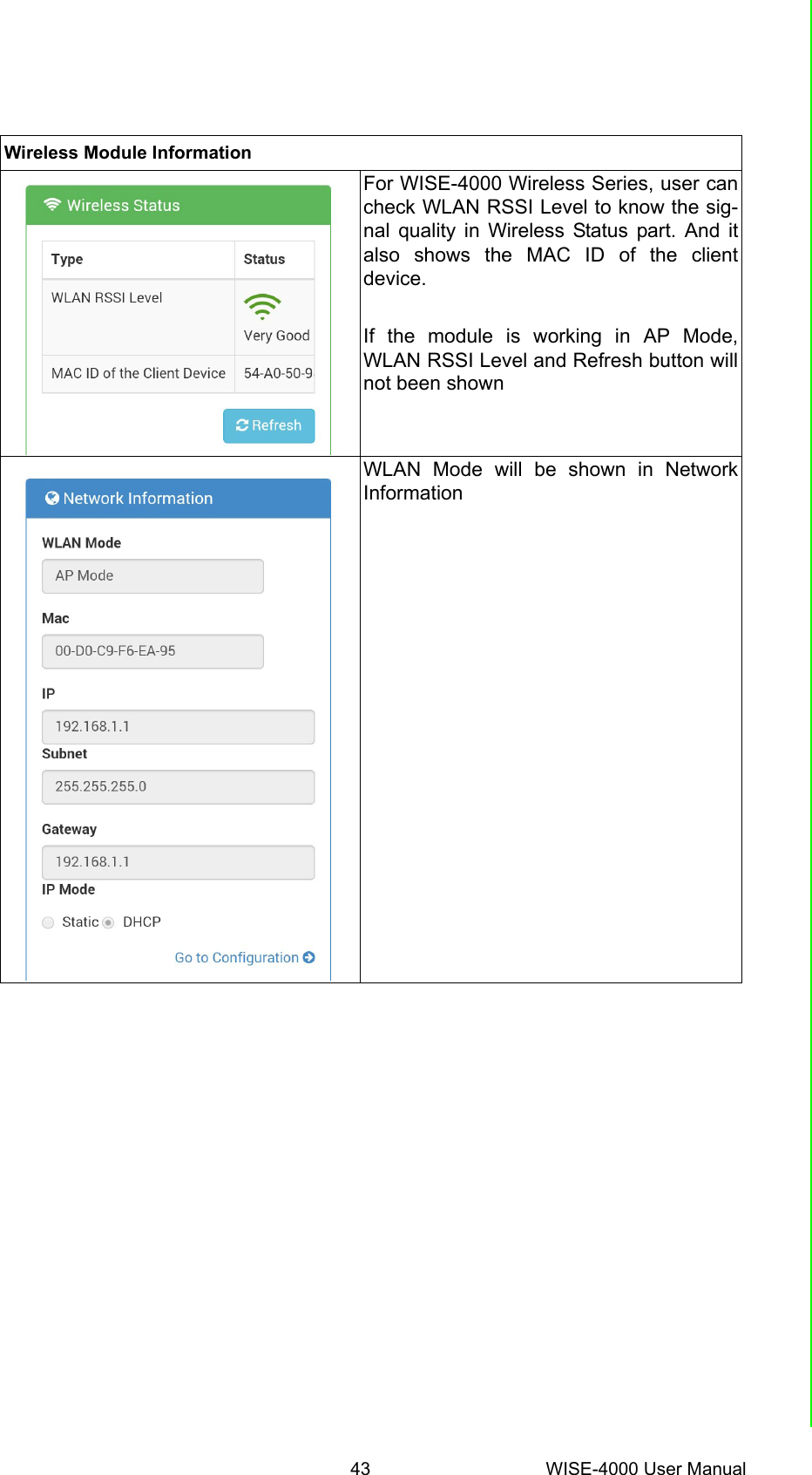
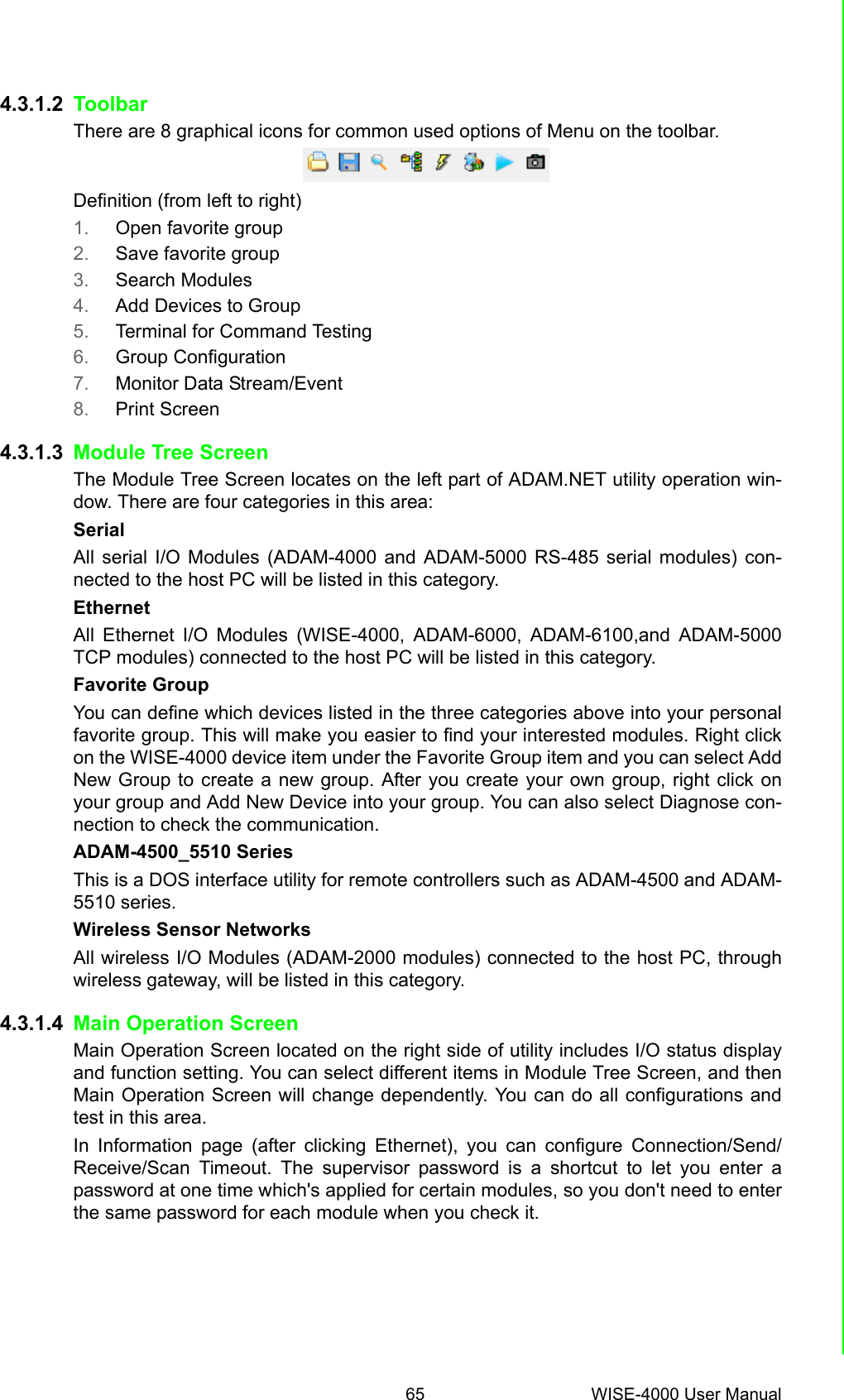
![47 WISE-4000 User ManualChapter 4 System Configuration[Infrastructure Mode]When using the module in Infrastructuremode, users need to enter the SSID of theAP that WISE going to access, and config-ure the security from here.After configuring the AP the WISE modulegoing to access, the network configurationalso needs to be defined in the Infrastruc-ture-Network.[Network]For WISE-4000/LAN wired module, youcan select the Connection mode as DHCPor Static IP and configure the IP address,Subnet address, and Default gateway.](https://usermanual.wiki/Advantech-Co/WISE4000.Users-Manual-2/User-Guide-2813915-Page-5.png)
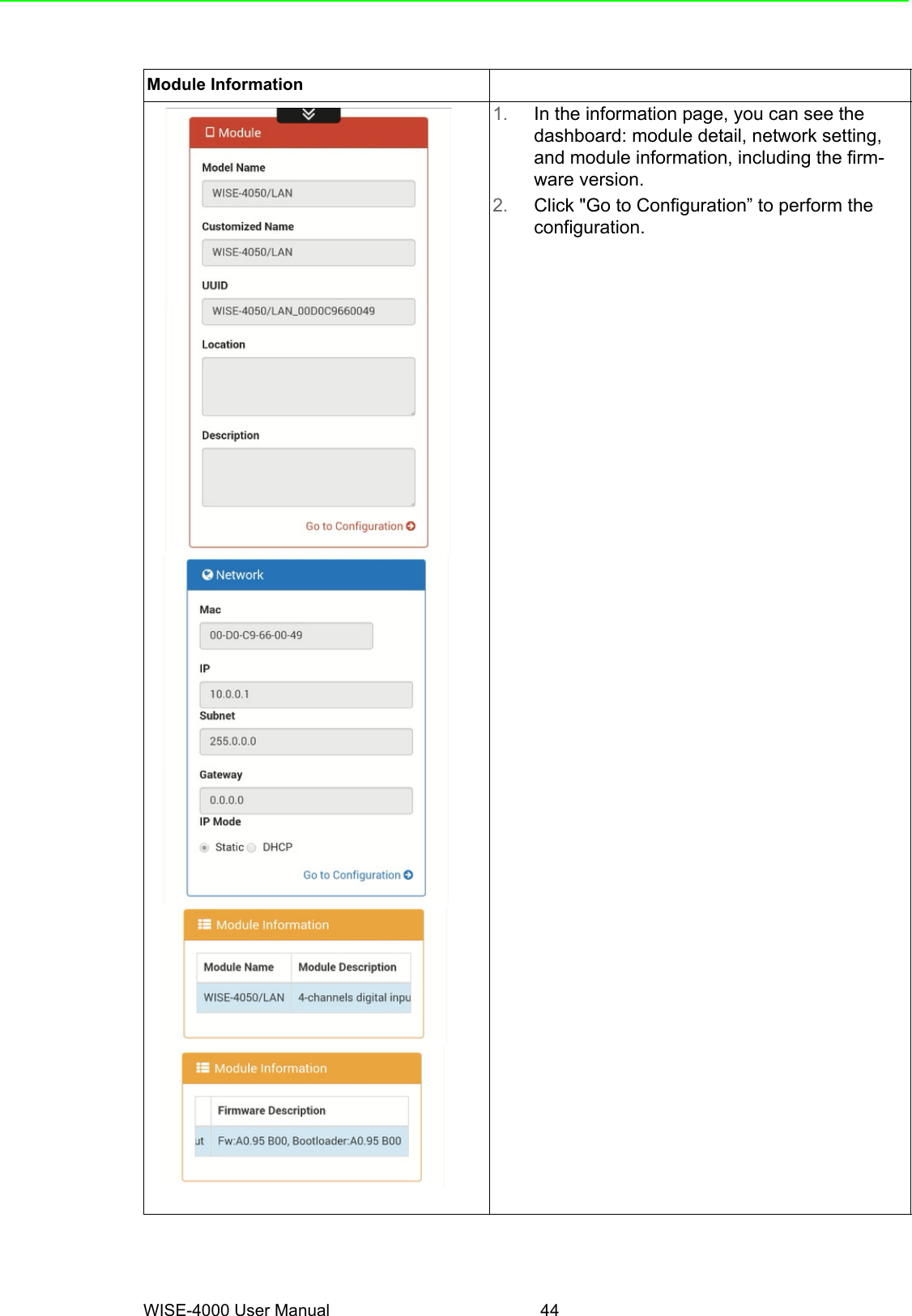
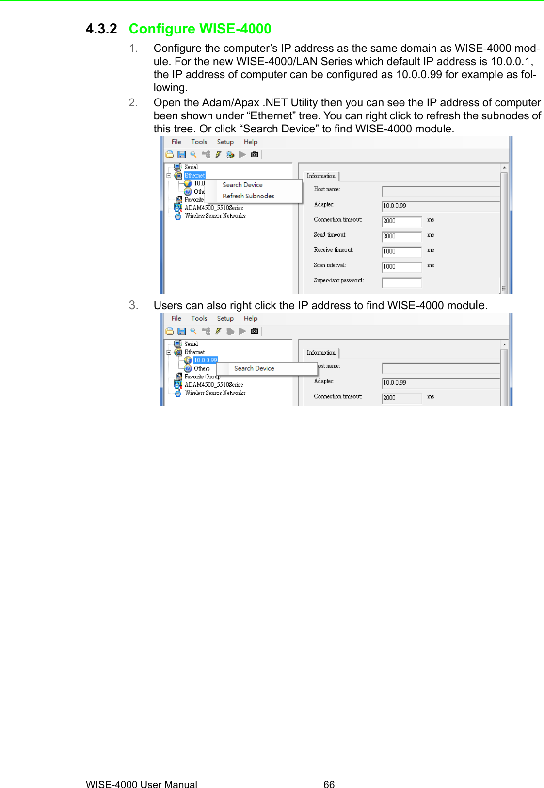
![WISE-4000 User Manual 48[Network App]You configure the web server port, HostIdle (timeout), and decide whether toenable communication WDT here[Time & Date]You can see the current time here, decidewhich time zone for your local time, andalso do the time calibration by read thetime from host devices[SNTP]You can enable the SNTP function, so themodule can act as a SNTP client to dotime synchronization from assigned SNTPserver.](https://usermanual.wiki/Advantech-Co/WISE4000.Users-Manual-2/User-Guide-2813915-Page-6.png)
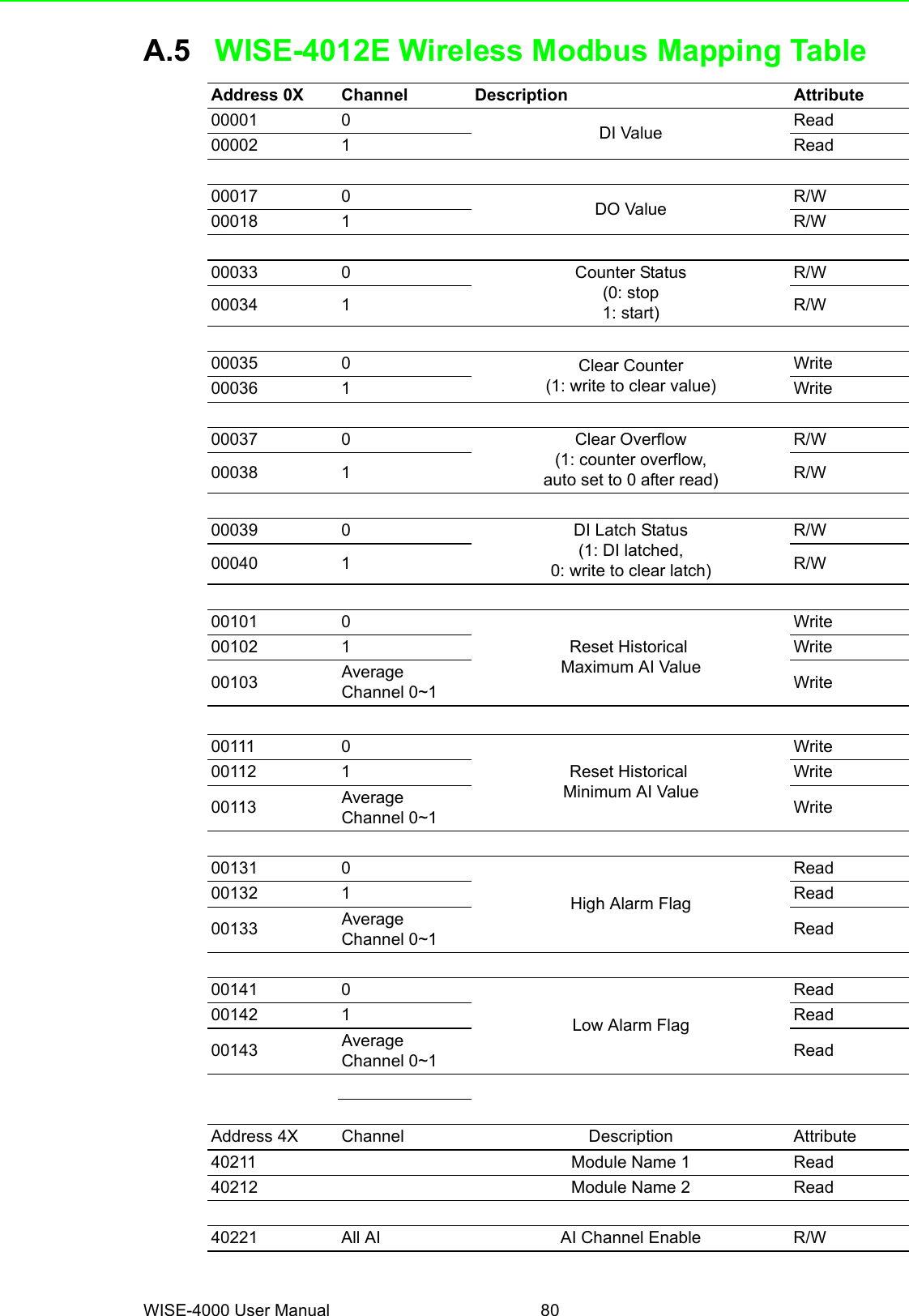
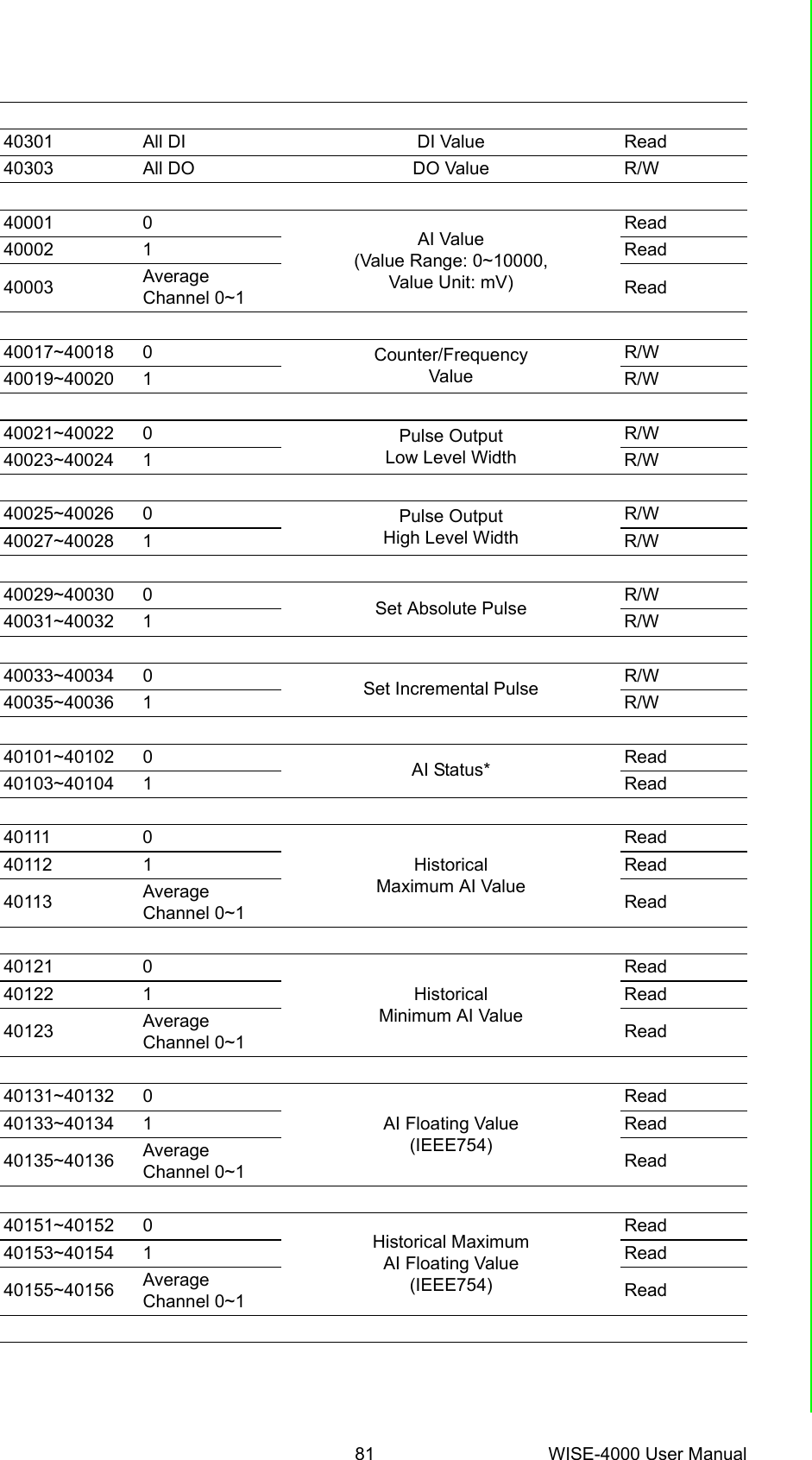
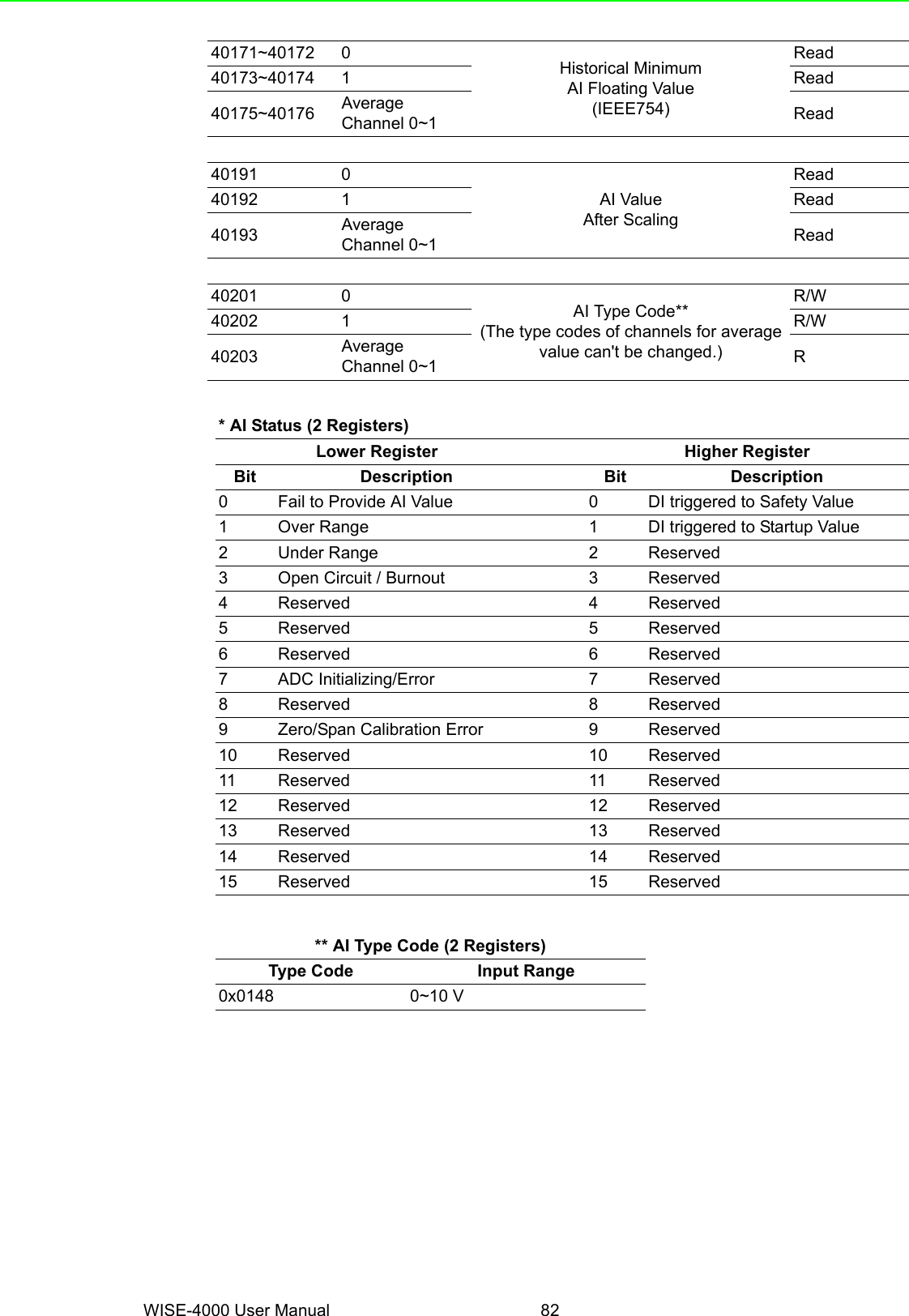
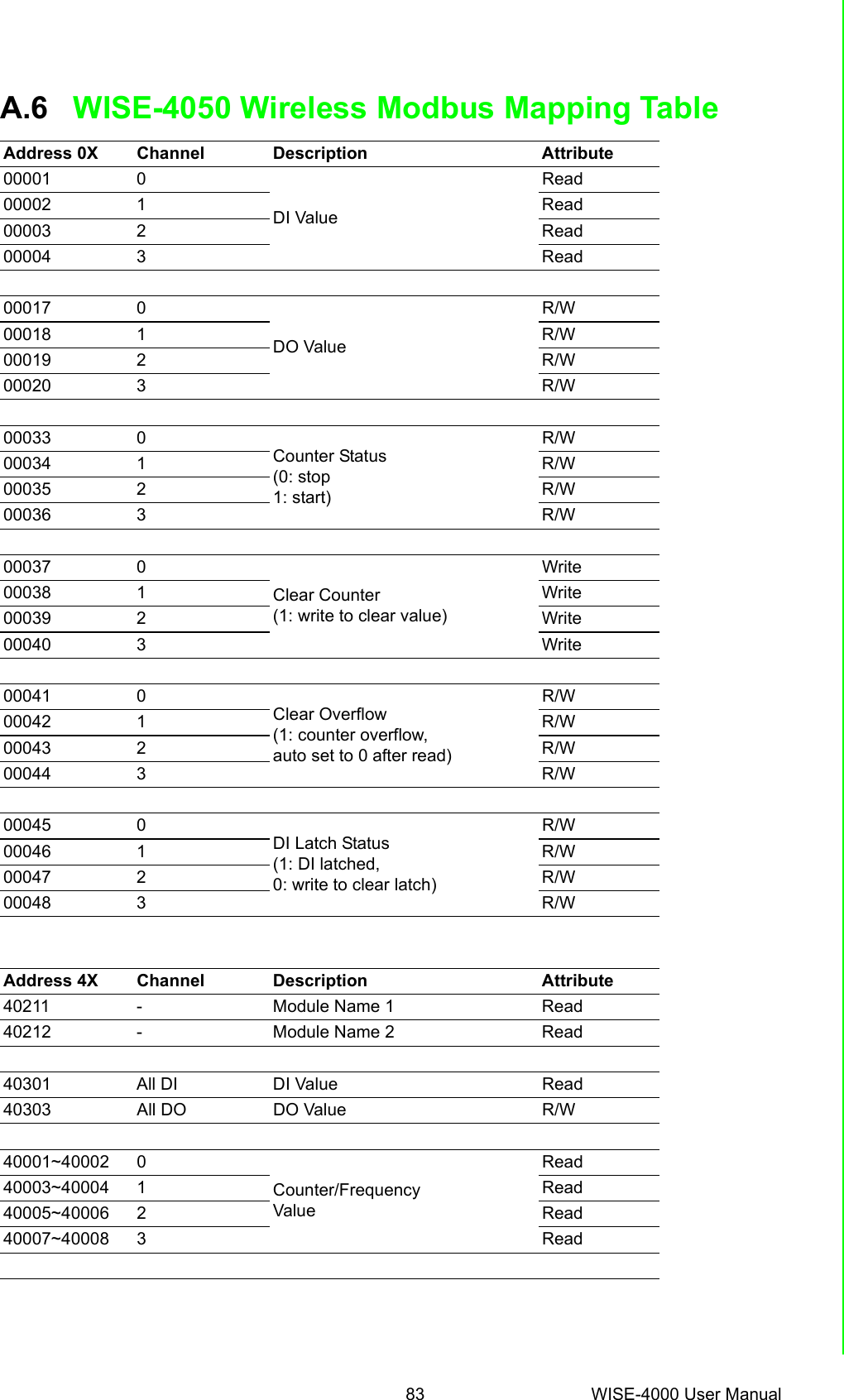
![49 WISE-4000 User ManualChapter 4 System Configuration[Modbus]In order to provide user with more flexibleand scalable in deploying module, thismodule remove the limitation of Modbusaddress setting and make it configurableas user's actual need. Basically, there'retwo kinds of Modbus address section (0Xand 4X) for you to configure each functionitem.[Control]Enable LocateIt can help user search module with lightsign. (Status LED will be constantly on for30 sec when it enabled.)Restore to DefaultThe system configuration of module willbe clear and restored to factory defaultwhen it enabled.Reset PasswordYou can reset the password hereSystem RestartThe system of this module will rebootwhen it enabled.](https://usermanual.wiki/Advantech-Co/WISE4000.Users-Manual-2/User-Guide-2813915-Page-7.png)
![WISE-4000 User Manual 50[General]After Communication WDT been enabledin "Network App" tab, you can enable theIO FSV triggered by communication WDTThe Scan Interval here decides the I/Opolling interval in the next part of the “I/OStatus”. This value will not be saved intothe module, so it is valid until the power isswitched off.[Firmware]User can upgrade the firmware file here.Or Upload/Download the configuration filefrom WISE-4000 wireless module.The following items will be saved in theconfiguration file:[Account]You can change the passwords of eachaccount here.ConfigurationInformation, Wireless, Network App, Time & Data, SNTP, Modbus, General Cloud, AccountI/O Status I/O ConfigurationAdvancedAccess Control, Data Logger (Data log and Cloud upload)](https://usermanual.wiki/Advantech-Co/WISE4000.Users-Manual-2/User-Guide-2813915-Page-8.png)
![51 WISE-4000 User ManualChapter 4 System ConfigurationI/O Status [Status]The I/O statuses are shown here, for theoutput status, you can also change the I/Ostatus here.](https://usermanual.wiki/Advantech-Co/WISE4000.Users-Manual-2/User-Guide-2813915-Page-9.png)
![WISE-4000 User Manual 52[Configuration]SettingUser can do detail I/O setting in the tab,include the Tag Name, range type, filter,and also the working mode.CalibrationFor the analog module, after login rootaccount, user can click calibration buttonto restore the factory calibration value.OverviewIn the end, there is an overview table forthe configuration summary of each chan-nel](https://usermanual.wiki/Advantech-Co/WISE4000.Users-Manual-2/User-Guide-2813915-Page-10.png)
![53 WISE-4000 User ManualChapter 4 System Configuration[Trend]The status trend of I/O will be shown here.Advanced Function - Access Control To avoid unauthorized access, you canmanage which host PC or device canremotely control the WISE-4000 moduleby IP or MAC Address.](https://usermanual.wiki/Advantech-Co/WISE4000.Users-Manual-2/User-Guide-2813915-Page-11.png)
![WISE-4000 User Manual 54Enable one of the rows and enter the IPaddress or MAC address which allows toaccess the WISE-4000 device.For WISE-4000 wireless modules, userscan only configure access control by theIP address, not the MAC addressAdvance Function - Data Log The WISE-4000 series supports data logfunctions, the I/O status can be logged inthe module and also be queried from themodule .Local Log Configuration[Enable Log]Start LogUsers can enable the data logger here](https://usermanual.wiki/Advantech-Co/WISE4000.Users-Manual-2/User-Guide-2813915-Page-12.png)
![55 WISE-4000 User ManualChapter 4 System Configuration[Log Conditions].By PeriodCheck the box to enable periodically log-ging, and the log period can be decided infollowing box. Pleased been noted that theperiod is increased by 0.1 sec, it means ifuser configure "600" here, the status of theI/O will be logged each minute.By Communication WDTIf the communication WDT has beenenabled, once the condition of the WDThas been met, the status of the I/O will belogged [General]Clear Log when Power UpDecided whether to keep last value whenthe logger had been restarted.Circular Log when Memory FullOnce the box been check, the data willbeen circular log when memory was full.Otherwise, the logger will stop.[Channel Setting]Users can configure which channel of themodule will be logged and decide whetherto log the data when the status is changedby checking the “Change of Status” box.](https://usermanual.wiki/Advantech-Co/WISE4000.Users-Manual-2/User-Guide-2813915-Page-13.png)
![WISE-4000 User Manual 56Local Viewer[Query Format]Users can decide which type of data hasbeen queried.[Query Filter]Filter ModeAmount of Latest Data: User can query the latest amount of data by this modeTime Filter: User can query the data from and to the time by configured here](https://usermanual.wiki/Advantech-Co/WISE4000.Users-Manual-2/User-Guide-2813915-Page-14.png)
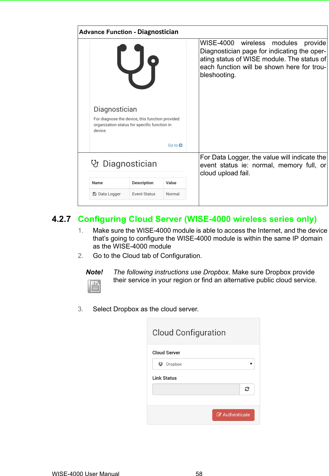
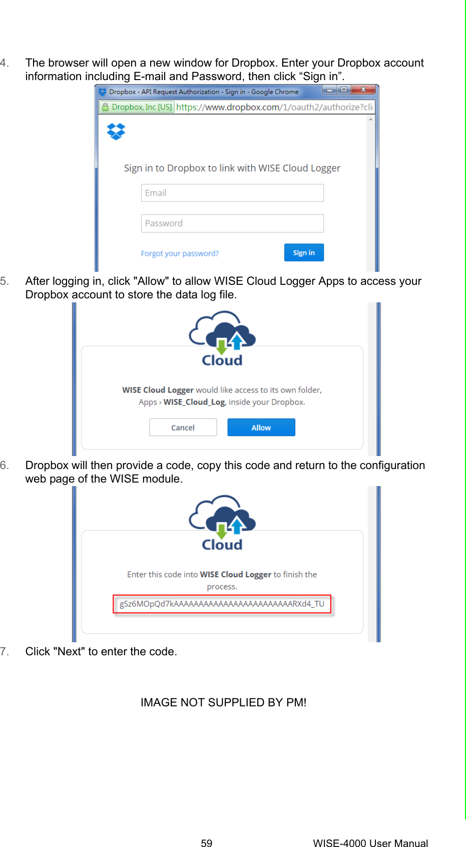
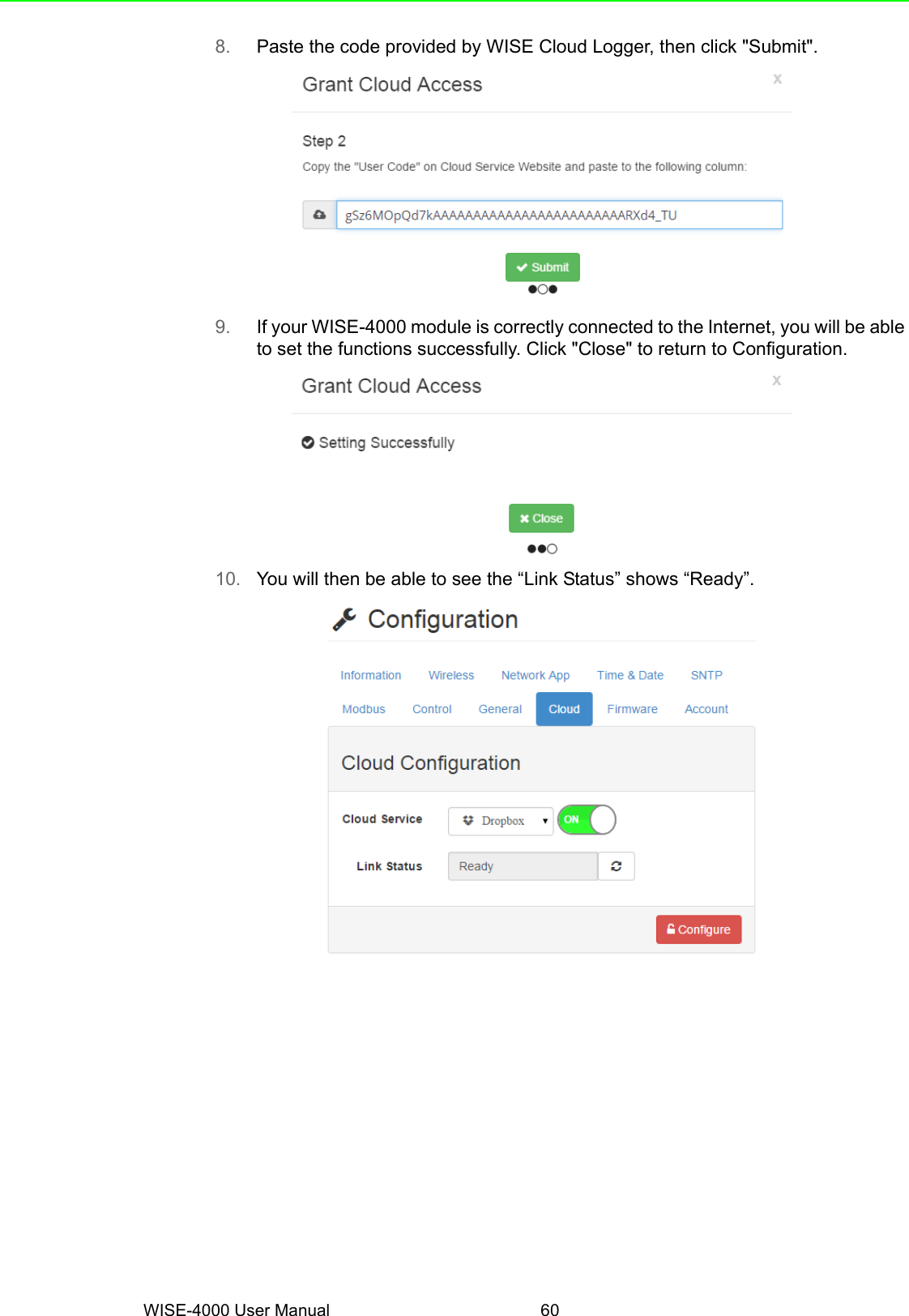
![57 WISE-4000 User ManualChapter 4 System ConfigurationAfter "Query" has been clicked, the datawill be shown in the dashboard and also inthe list. Users can click the "Save" buttonto save the logged data.Refer to B.2.4 for a detailed definition ofeach column. For example: Log Type 128means periodical logging, I/O Type 1means DI statusCloud Upload (WISE-4000 wireless series only)[Enable Cloud Upload]Start UploadAfter configuring the cloud server asdescribed below, users can start automati-cally upload functions here.[Upload Mode]Time Periodic Interval mode: Data can be upload be configured periodItem Periodic Interval mode: Data can be upload once it reaches the configured of sample data](https://usermanual.wiki/Advantech-Co/WISE4000.Users-Manual-2/User-Guide-2813915-Page-15.png)


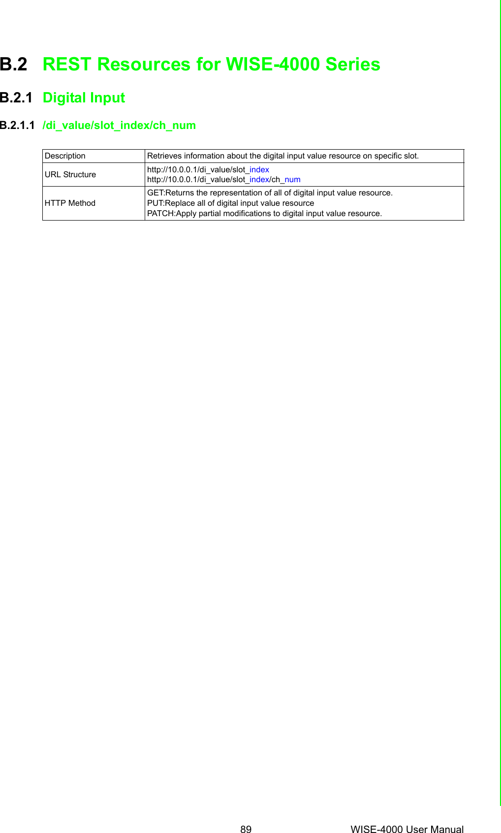
![WISE-4000 User Manual 90GETMultiple Channel Request:GET /di_value/slot_indexSingle Channel Request:GET /di_value/slot_index/ch_num[Example]Request: GET /di_value/slot_0Content-type: application/jsonResponse: 200 OK{ "DIVal": [ { "Ch":0, "Md":0, "Stat":1, "Val":1, "Cnting":0, "ClrCnt":0, "OvLch": 0 }, { "Ch":1, "Md":0, "Stat":0, "Val":0, "Cnting":0, "ClrCnt":0, "OvLch": 0 }, { "Ch":2, "Md":1, "Stat":0, "Val":3378, "Cnting":1, "ClrCnt":0, "OvLch": 0 }, { "Ch":3, "Md":3, "Stat":0, "Val":1, "Cnting":0, "ClrCnt":0, "OvLch": 0 } ]}Request : GET /di_value/slot_0/ch_2Content-type: application/jsonResponse: 200 OK{ "Ch":2, "Md":0, "Stat":1, "Val":1, "Cnting":0, "ClrCnt":0, "OvLch": 0}](https://usermanual.wiki/Advantech-Co/WISE4000.Users-Manual-2/User-Guide-2813915-Page-48.png)
![91 WISE-4000 User ManualAppendix B REST for WISE-4000 SeriesPUTSingle/Multiple Channel Request:PUT /di_value/slot_indexSingle Channel Request:PUT /di_value/slot_index/ch_num[Example]Request: PUT /di_value/slot_0Content-type: application/json{"DIVal": [ { "Ch":0, "Md":0, "Stat":0, "Val":0, "Cnting":0, "ClrCnt":0, "OvLch": 0 }, { "Ch":1, "Md":0, "Stat":0, "Val":0, "Cnting":0, "ClrCnt":0, "OvLch": 0 }, { "Ch":2, "Md":1, "Stat":0, "Val":3378, "Cnting":0, "ClrCnt":1, "OvLch": 0 }, { "Ch":3, "Md":3, "Stat":0, "Val":0, "Cnting":0, "ClrCnt":0, "OvLch": 0 } ]}Response: 200 OKRequest: PUT /di_value/slot_0/ch_2Content-type: application/json{ "Ch":2, "Md":1, "Stat":0, "Val":3378, "Cnting":0, "ClrCnt":1, "OvLch": 0}Response: 200 OK](https://usermanual.wiki/Advantech-Co/WISE4000.Users-Manual-2/User-Guide-2813915-Page-49.png)
![WISE-4000 User Manual 92JSON array name definition:PATCHSingle/Multiple Channel Request:PATCH /di_value/slot_indexSingle Channel Request:PATCH /di_value/slot_index/ch_num[Example]Request: PATCH /di_value/slot_0Content-type: application/json{"DIVal": [ { "Ch":2, "Cnting": 1 }, { "Ch":3, "OvLch":0 } ]}Response: 200 OKRequest: PATCH /di_value/slot_0/ch_3Content-type: application/json{"Ch":3, "ClrCnt":1}Response: 200 OKField Abbreviation Data TypeArray of Digital input configurations DIVal Array](https://usermanual.wiki/Advantech-Co/WISE4000.Users-Manual-2/User-Guide-2813915-Page-50.png)

![95 WISE-4000 User ManualAppendix B REST for WISE-4000 SeriesGETMultiple Channel Request:GET /do_value/slot_indexSingle Channel Request:GET /do_value/slot_index/ch_num[Example]Request: GET /do_value/slot_0Content-type: application/jsonResponse: 200 OK{ "DOVal": [ { "Ch":0, "Md":0, "Stat":1, "Val":1, "PsCtn":0, "PsStop":0, "PsIV": 0 }, { "Ch":1, "Md":0, "Stat":0, "Val":0, "PsCtn":0, "PsStop":0, "PsIV": 0 }, { "Ch":2, "Md":1, "Stat":1, "Val":3378, "PsCtn":0, "PsStop":0, "PsIV": 0 }, { "Ch":3, "Md":3, "Stat":1, "Val":1, "PsCtn":0, "PsStop":0, "PsIV": 0 } ]}Request : GET /do_value/slot_0/ch_2Content-type: application/jsonResponse: 200 OK{ "Ch":2, "Md":0, "Stat":1, "Val":1, "PsCtn":0, "PsStop":0, "PsIV": 0}](https://usermanual.wiki/Advantech-Co/WISE4000.Users-Manual-2/User-Guide-2813915-Page-53.png)
![WISE-4000 User Manual 96PUTSingle/Multiple Channel Request:PUT /do_value/slot_indexSingle Channel Request:PUT /do_value/slot_index/ch_num[Example]Request: PUT /do_value/slot_0Content-type: application/json{ "DOVal": [ { "Ch":0, "Md":0, "Stat":1, "Val":1, "PsCtn":0, "PsStop":0, "PsIV": 0 }, { "Ch":1, "Md":0, "Stat":0, "Val":0, "PsCtn":0, "PsStop":0, "PsIV": 0 }, { "Ch":2, "Md":1, "Stat":1, "Val":3378, "PsCtn":0, "PsStop":0, "PsIV": 0 }, { "Ch":3, "Md":3, "Stat":1, "Val":1, "PsCtn":0, "PsStop":0, "PsIV": 0 } ]}Response: 200 OKRequest: PUT /do_value/slot_0/ch_2Content-type: application/json{ "Ch":2, "Md":2, "Stat":0, "Val":0, "PsCtn":0, "PsStop":0, "PsIV": 0}Response: 200 OK](https://usermanual.wiki/Advantech-Co/WISE4000.Users-Manual-2/User-Guide-2813915-Page-54.png)
![97 WISE-4000 User ManualAppendix B REST for WISE-4000 SeriesJSON array name definition:PATCHSingle/Multiple Channel Request:PATCH /do_value/slot_indexSingle Channel Request:PATCH /do_value/slot_index/ch_num[Example]Request: PATCH /do_value/slot_0Content-type: application/json{"DOVal": [ { "Ch":2, "Md": 2 }, { "Ch":3, "PsStop":1 } ]}Response: 200 OKRequest: PATCH /do_value/slot_0/ch_3Content-type: application/json{"Ch":3, "PsCtn":1}Response: 200 OKField Abbreviation Data TypeArray of Digital input configurations DOVal Array](https://usermanual.wiki/Advantech-Co/WISE4000.Users-Manual-2/User-Guide-2813915-Page-55.png)

![WISE-4000 User Manual 100GETMultiple Channel Request:GET /ai_value/slot_indexSingle Channel Request:GET /ai_value/slot_index/ch_num[Example]Request : GET /ai_value/slot_0Content-type: application/jsonResponse: 200 OK{ "AIVal": [ { "Ch":0,"En":1, "Rng":328, "Val":148, "Eg":650, "Evt":0, "LoA": 0, "HiA": 0, "HVal":190, "HEg":1250, "LVal":15, "LEg":500, "SVal":148, "ClrH": 0, "ClrL": 0 }, { "Ch":1,"En":1, "Rng":328, "Val":0, "Eg":0, "Evt":0, "LoA":0, "HiA":0, "HVal":0, "HEg":0, "LVal":0, "LEg":0, "SVal":0, "ClrH": 0, "ClrL": 0 }, { "Ch":2,"En":1,](https://usermanual.wiki/Advantech-Co/WISE4000.Users-Manual-2/User-Guide-2813915-Page-58.png)
![101 WISE-4000 User ManualAppendix B REST for WISE-4000 Series "Rng":328, "Val":0, "Eg":0, "Evt":8, "LoA":0, "HiA":0, "HVal":0, "HEg":0, "LVal":0, "LEg":0, "SVal":0, "ClrH": 0, "ClrL": 0 }, { "Ch":3,"En":1, "Rng":328, "Val":0, "Eg":0, "Evt":0, "LoA":0, "HiA":0, "HVal":0, "HEg":0, "LVal":0, "LEg":0, "SVal":0, "ClrH": 0, "ClrL": 0 }, { "Ch":4,"En":1, "Rng":328, "Val":0, "Eg":0, "Evt":0, "LoA":0, "HiA":0, "HVal":0, "HEg":0, "LVal":0, "LEg":0, "SVal":0, "ClrH": 0, "ClrL": 0 } ]}Request : GET /ai_value/slot_0/ch_2Content-type: application/jsonResponse: 200 OK{ "Ch":2,"En":1, "Rng":328, "Val":0, "Eg":0, "Evt":8, "LoA":0, "HiA":0, "HVal":0, "HEg":0, "LVal":0, "LEg":0, "SVal":0, "ClrH": 0, "ClrL": 0}PUT None](https://usermanual.wiki/Advantech-Co/WISE4000.Users-Manual-2/User-Guide-2813915-Page-59.png)
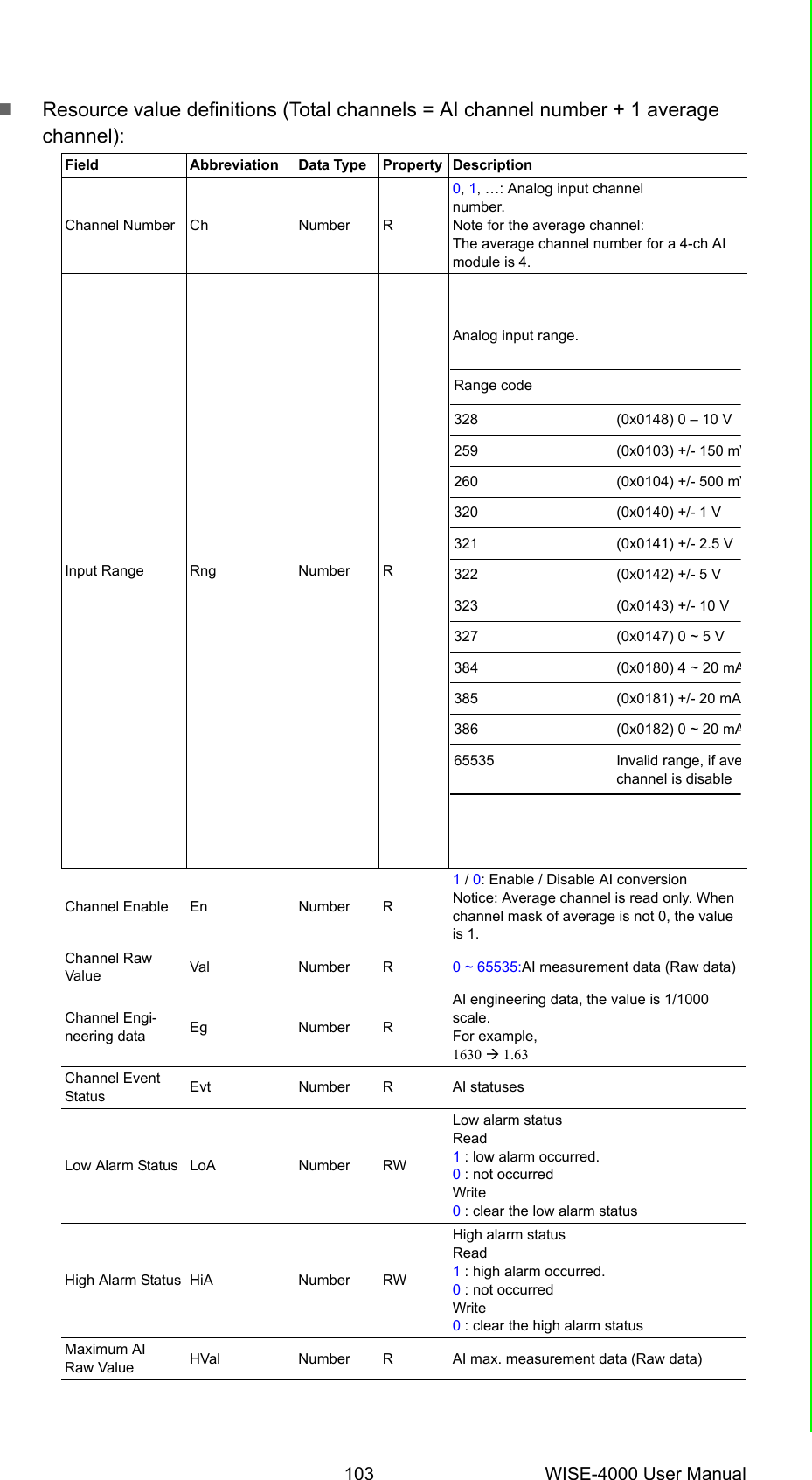
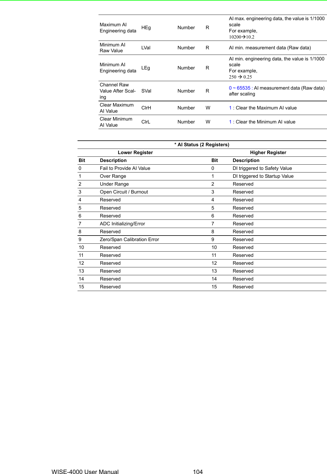
![WISE-4000 User Manual 102JSON array name definition:PATCHSingle/Multi Channel Request:PATCH /ai_value/slot_indexSingle Channel Request:PATCH /ai_value/slot_index/ch_num[Example]Request: PATCH /ai_value/slot_0Content-type: application/json{"AIVal": [ { "Ch":2, "LoA": 0 }, { "Ch":3, "HiA":0 } ]}Response: 200 OKRequest: PATCH /ai_value/slot_0/ch_3Content-type: application/json{ "LoA":0}Response: 200 OKField Abbreviation Data TypeArray of Analog input configurations AIVal Array](https://usermanual.wiki/Advantech-Co/WISE4000.Users-Manual-2/User-Guide-2813915-Page-60.png)
![105 WISE-4000 User ManualAppendix B REST for WISE-4000 SeriesB.2.4 Data LoggerB.2.4.1 /log_messageDescription Retrieves the log data in system memory. URL Structure http://10.0.0.1/log_messageHTTP Method GET: According to the setting of filtering, server returns the all/partial of logged data.GETRequest:GET /log_message[Example]:Request: GET /log_message for WISE-4060/LAN moduleContent-type: application/jsonResponse: 200 OK{ "LogMsg": [ { "PE":128, "TIM":"2014-11-11T15:48:32+08:00","UID":"ADAM-T160_00D0C9FE1601","MAC":"00-D0-C9-FE-16-01","Record" : [[0,3,3,1],[0,2,4,150],[0,5,5,250]] }, { "PE":128, "TIM":"2014-11-11T15:49:44+08:00","UID":"ADAM-T160_00D0C9FE1601","MAC":"00-D0-C9-FE-16-01","Record" : [[0,3,3,0],[0,2,4,140],[0,5,5,240]] }, { "PE":128, "TIM":"2014-11-11T15:51:02+08:00","UID":"ADAM-T160_00D0C9FE1601","MAC":"00-D0-C9-FE-16-01","Record" : [[0,3,3,0],[0,2,4,130],[0,5,5,230]] } ]}](https://usermanual.wiki/Advantech-Co/WISE4000.Users-Manual-2/User-Guide-2813915-Page-63.png)
![WISE-4000 User Manual 106JSON array name definition:Resource value definitions:RemarksField Abbreviation Data TypeArray of log messages LogMsg ArrayArray of I/O records Record ArrayField Abbreviations Data type Property DescriptionPeriodic/Event 128 Number RRecording mode of storageTimestamp TIM String RTimestamp of the storage“Coordinated Universal Time (UTC)Ex. “1415757750” corresponds to November 12, 2014, 2:02:30 am, Standard Time.(meanwhile, 2014, 10:02:30 am, Taipei Time.)“Local Date/Time according GMT time zone (ISO 8601)Ex. “1994-11-05T08:15:30-05:00” corresponds to Novem-ber 5, 1994, 8:15:30 am, US Eastern Standard Time.UUID UID String R Universally Unique Identifier (UUID)Max. 32 charactersMAC ID MAC String R MAC address.(12+5) characters, ex, “00-D0-C9-F0-63-F7Recording message Record Array R* The information in array is as follows.[Slot-index, Channel-index, I/O-type-index, I/O-value]* The data type in array is as follows. [Number, Number, Number, Number]Notice: When the I/O-type-index is engineering type (12, 13, 14, 18), the I/O value is 1/1000 scale.1Event fromDI2DO4AI8AO16 WDT128 PeriodicIndex Recording I/O-type of the storage0Invalid1DI Logic Status2DI Counter value3DI Frequency value4DO Logic Status5DO Absolute Pulse Output value6DO Incremental Pulse Output Value7AI value8Historical Maximum AI value9Historical Minimum AI value10 AI value after scaling11 AI status flags12 AI engineering value13 Historical Maximum AI engineering value14 Historical Minimum AI engineering value15 AO value16 AO value after scaling17 AO status flags18 AO engineering value](https://usermanual.wiki/Advantech-Co/WISE4000.Users-Manual-2/User-Guide-2813915-Page-64.png)