Advantech Co WISE4000 IoT Wireless I/O Module User Manual V4 12 EA User Manual
Advantech Co Ltd IoT Wireless I/O Module V4 12 EA User Manual
Contents
- 1. Users Manual-1
- 2. Users Manual-2
Users Manual-2
43 WISE-4000 User Manual
Chapter 4 System Configuration
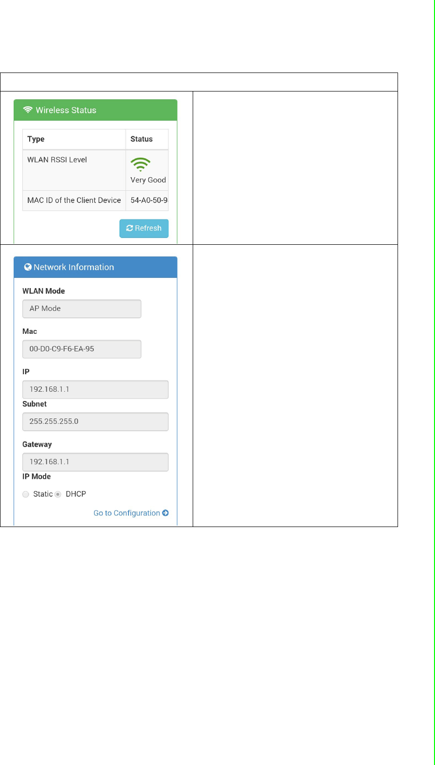
Wireless Module Information
For WISE-4000 Wireless Series, user can
check WLAN RSSI Level to know the sig-
nal quality in Wireless Status part. And it
also shows the MAC ID of the client
device.
If the module is working in AP Mode,
WLAN RSSI Level and Refresh button will
not been shown
WLAN Mode will be shown in Network
Information
WISE-4000 User Manual 44
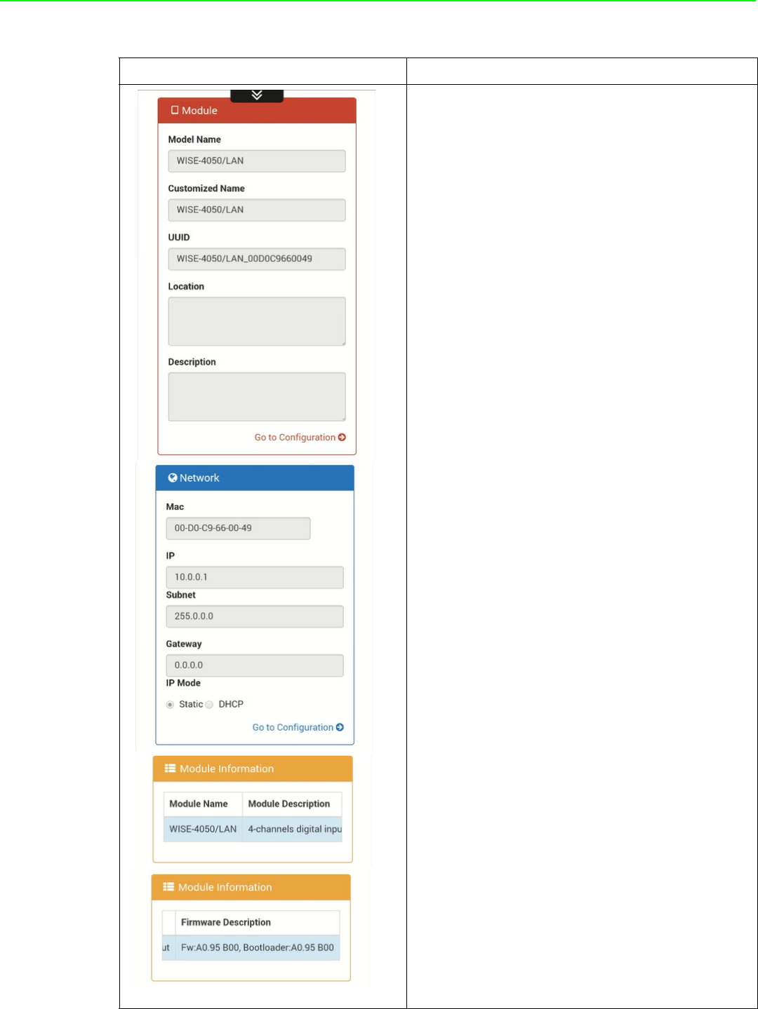
Module Information
1. In the information page, you can see the
dashboard: module detail, network setting,
and module information, including the firm-
ware version.
2. Click "Go to Configuration” to perform the
configuration.
45 WISE-4000 User Manual
Chapter 4 System Configuration
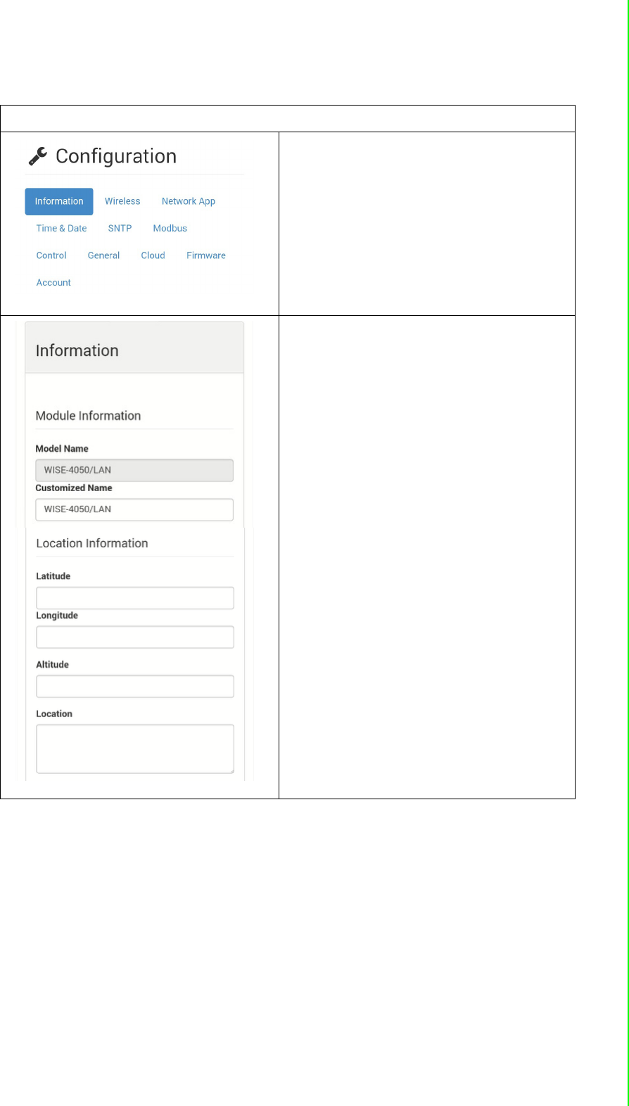
Module Configuration
You can click different tab to switch the
item you are going to configure
[Information]
Customized Name / UUID
Means model name and UUID of the mod-
ule. You also can rename it for recognition
if required.
Description
You can add comments on this module for
recognition.
Location Information
You can note the location information for
the module
WISE-4000 User Manual 46
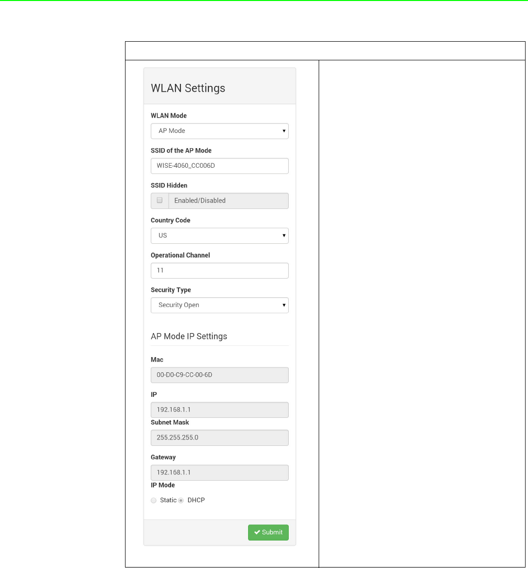
Wireless (WISE-4000 Wireless module only)
[AP Mode]
When using the module in AP mode, users
can configure the SSID and also decide
how the WISE module works as an AP,
including the security.
The AP-Network is fixed and does not
allow user to make their own changes.
47 WISE-4000 User Manual
Chapter 4 System Configuration
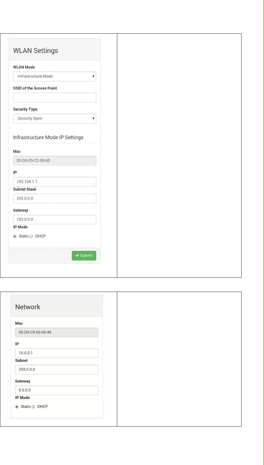
[Infrastructure Mode]
When using the module in Infrastructure
mode, users need to enter the SSID of the
AP that WISE going to access, and config-
ure the security from here.
After configuring the AP the WISE module
going to access, the network configuration
also needs to be defined in the Infrastruc-
ture-Network.
[Network]
For WISE-4000/LAN wired module, you
can select the Connection mode as DHCP
or Static IP and configure the IP address,
Subnet address, and Default gateway.
WISE-4000 User Manual 48
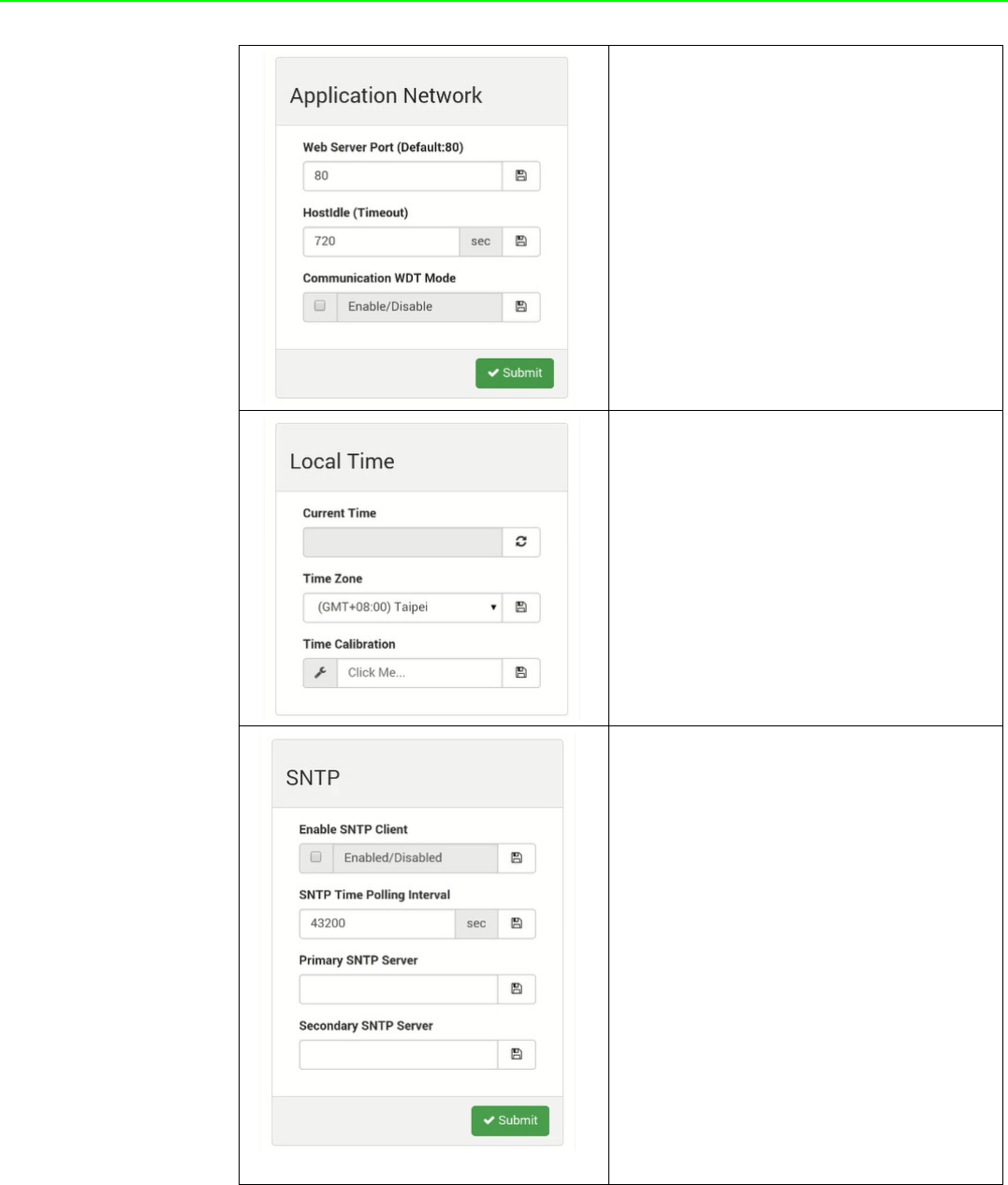
[Network App]
You configure the web server port, Host
Idle (timeout), and decide whether to
enable communication WDT here
[Time & Date]
You can see the current time here, decide
which time zone for your local time, and
also do the time calibration by read the
time from host devices
[SNTP]
You can enable the SNTP function, so the
module can act as a SNTP client to do
time synchronization from assigned SNTP
server.
49 WISE-4000 User Manual
Chapter 4 System Configuration
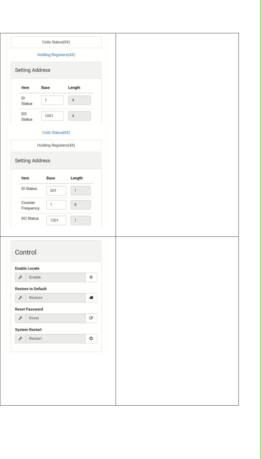
[Modbus]
In order to provide user with more flexible
and scalable in deploying module, this
module remove the limitation of Modbus
address setting and make it configurable
as user's actual need. Basically, there're
two kinds of Modbus address section (0X
and 4X) for you to configure each function
item.
[Control]
Enable Locate
It can help user search module with light
sign. (Status LED will be constantly on for
30 sec when it enabled.)
Restore to Default
The system configuration of module will
be clear and restored to factory default
when it enabled.
Reset Password
You can reset the password here
System Restart
The system of this module will reboot
when it enabled.
WISE-4000 User Manual 50
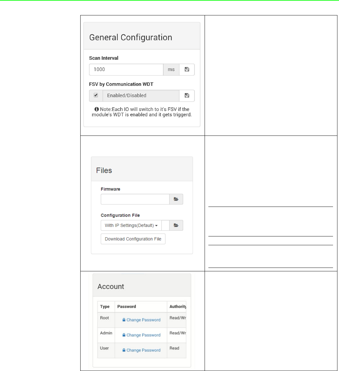
[General]
After Communication WDT been enabled
in "Network App" tab, you can enable the
IO FSV triggered by communication WDT
The Scan Interval here decides the I/O
polling interval in the next part of the “I/O
Status”. This value will not be saved into
the module, so it is valid until the power is
switched off.
[Firmware]
User can upgrade the firmware file here.
Or Upload/Download the configuration file
from WISE-4000 wireless module.
The following items will be saved in the
configuration file:
[Account]
You can change the passwords of each
account here.
Configuration
Information, Wireless, Network
App, Time & Data, SNTP,
Modbus, General Cloud,
Account
I/O Status I/O Configuration
Advanced
Access Control,
Data Logger (Data log and Cloud
upload)
51 WISE-4000 User Manual
Chapter 4 System Configuration
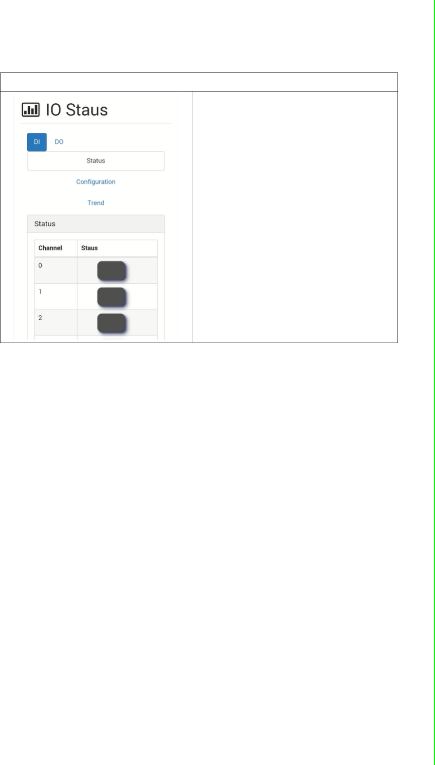
I/O Status
[Status]
The I/O statuses are shown here, for the
output status, you can also change the I/O
status here.
WISE-4000 User Manual 52
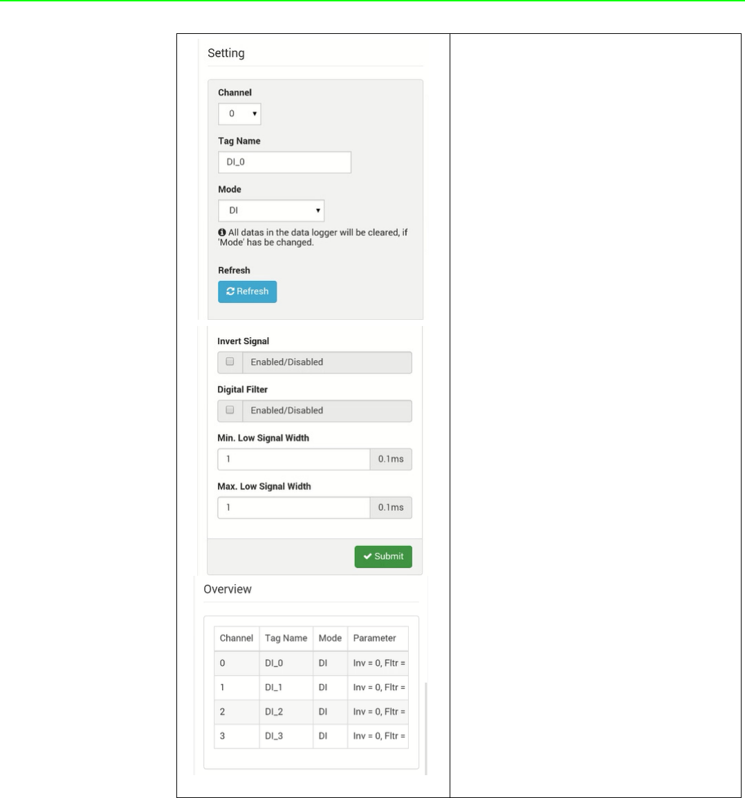
[Configuration]
Setting
User can do detail I/O setting in the tab,
include the Tag Name, range type, filter,
and also the working mode.
Calibration
For the analog module, after login root
account, user can click calibration button
to restore the factory calibration value.
Overview
In the end, there is an overview table for
the configuration summary of each chan-
nel
53 WISE-4000 User Manual
Chapter 4 System Configuration
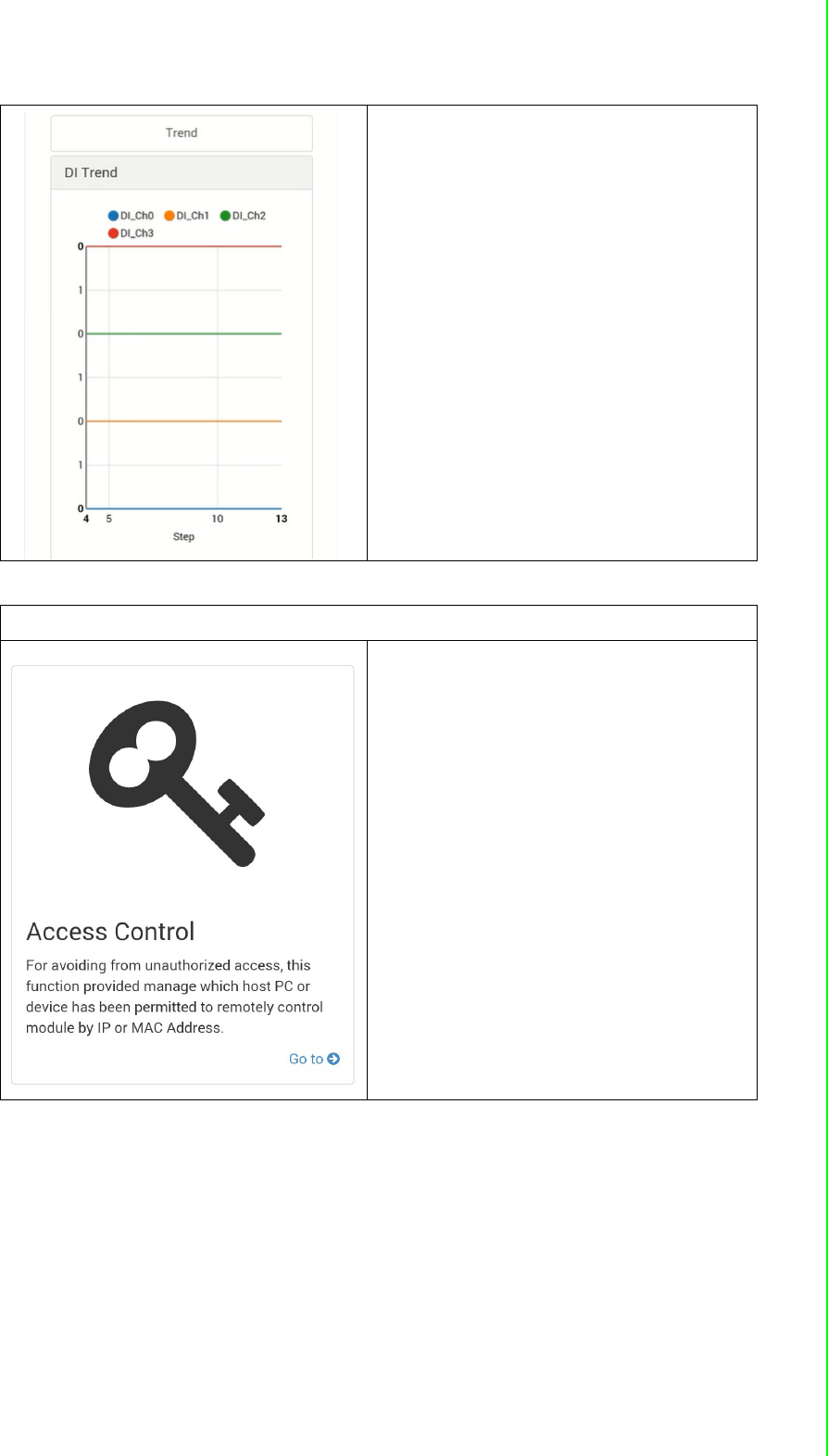
[Trend]
The status trend of I/O will be shown here.
Advanced Function - Access Control
To avoid unauthorized access, you can
manage which host PC or device can
remotely control the WISE-4000 module
by IP or MAC Address.
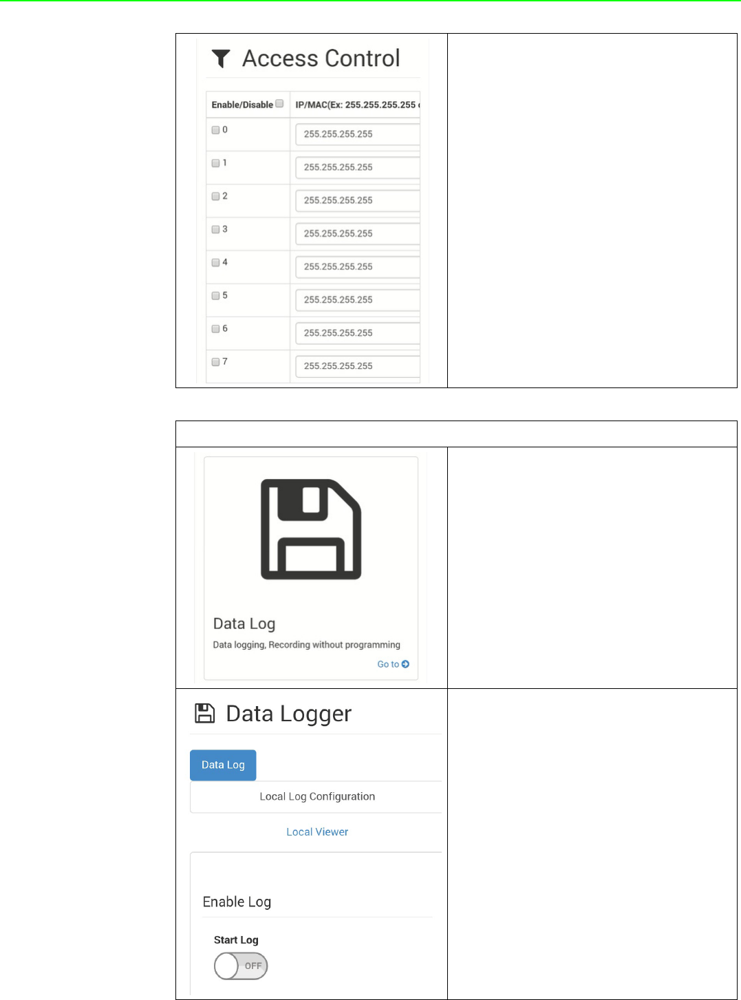
WISE-4000 User Manual 54
Enable one of the rows and enter the IP
address or MAC address which allows to
access the WISE-4000 device.
For WISE-4000 wireless modules, users
can only configure access control by the
IP address, not the MAC address
Advance Function - Data Log
The WISE-4000 series supports data log
functions, the I/O status can be logged in
the module and also be queried from the
module .
Local Log Configuration
[Enable Log]
Start Log
Users can enable the data logger here
55 WISE-4000 User Manual
Chapter 4 System Configuration
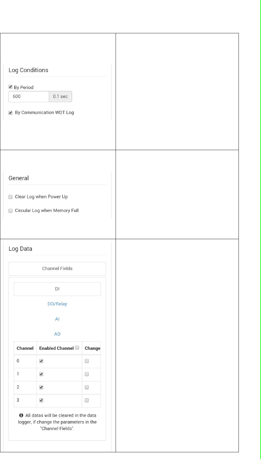
[Log Conditions].
By Period
Check the box to enable periodically log-
ging, and the log period can be decided in
following box. Pleased been noted that the
period is increased by 0.1 sec, it means if
user configure "600" here, the status of the
I/O will be logged each minute.
By Communication WDT
If the communication WDT has been
enabled, once the condition of the WDT
has been met, the status of the I/O will be
logged
[General]
Clear Log when Power Up
Decided whether to keep last value when
the logger had been restarted.
Circular Log when Memory Full
Once the box been check, the data will
been circular log when memory was full.
Otherwise, the logger will stop.
[Channel Setting]
Users can configure which channel of the
module will be logged and decide whether
to log the data when the status is changed
by checking the “Change of Status” box.
WISE-4000 User Manual 56
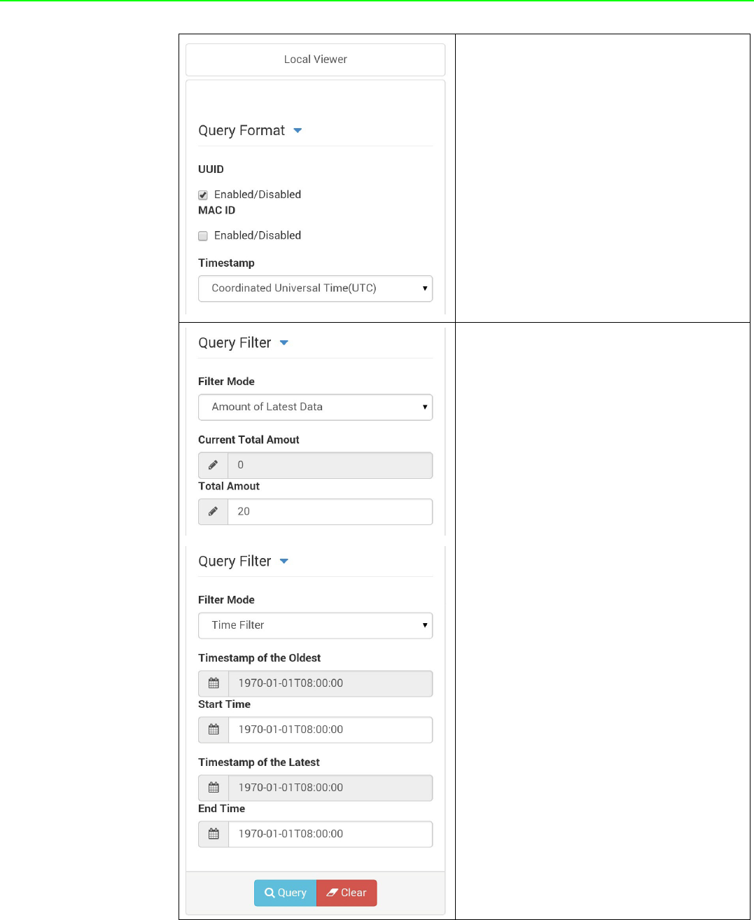
Local Viewer
[Query Format]
Users can decide which type of data has
been queried.
[Query Filter]
Filter Mode
Amount of Latest Data: User
can query the latest amount of
data by this mode
Time Filter: User can query the
data from and to the time by
configured here
57 WISE-4000 User Manual
Chapter 4 System Configuration
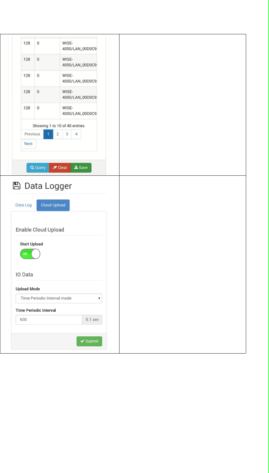
After "Query" has been clicked, the data
will be shown in the dashboard and also in
the list. Users can click the "Save" button
to save the logged data.
Refer to B.2.4 for a detailed definition of
each column. For example: Log Type 128
means periodical logging, I/O Type 1
means DI status
Cloud Upload
(WISE-4000 wireless series only)
[Enable Cloud Upload]
Start Upload
After configuring the cloud server as
described below, users can start automati-
cally upload functions here.
[Upload Mode]
Time Periodic Interval mode: Data
can be upload be configured
period
Item Periodic Interval mode: Data
can be upload once it reaches the
configured of sample data
WISE-4000 User Manual 58
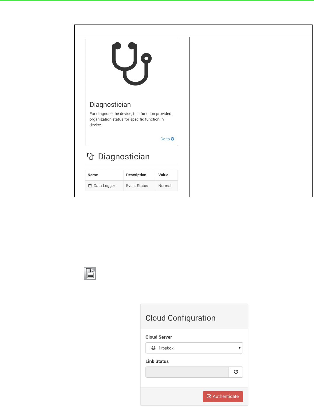
4.2.7 Configuring Cloud Server (WISE-4000 wireless series only)
1. Make sure the WISE-4000 module is able to access the Internet, and the device
that’s going to configure the WISE-4000 module is within the same IP domain
as the WISE-4000 module
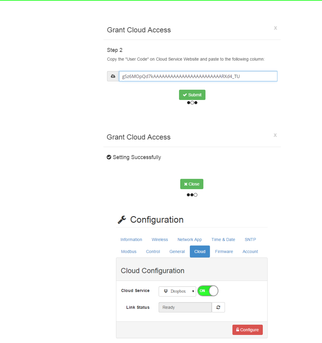
2. Go to the Cloud tab of Configuration.
3. Select Dropbox as the cloud server.
Advance Function - Diagnostician
WISE-4000 wireless modules provide
Diagnostician page for indicating the oper-
ating status of WISE module. The status of
each function will be shown here for trou-
bleshooting.
For Data Logger, the value will indicate the
event status ie: normal, memory full, or
cloud upload fail.
Note! The following instructions use Dropbox. Make sure Dropbox provide
their service in your region or find an alternative public cloud service.
59 WISE-4000 User Manual
Chapter 4 System Configuration
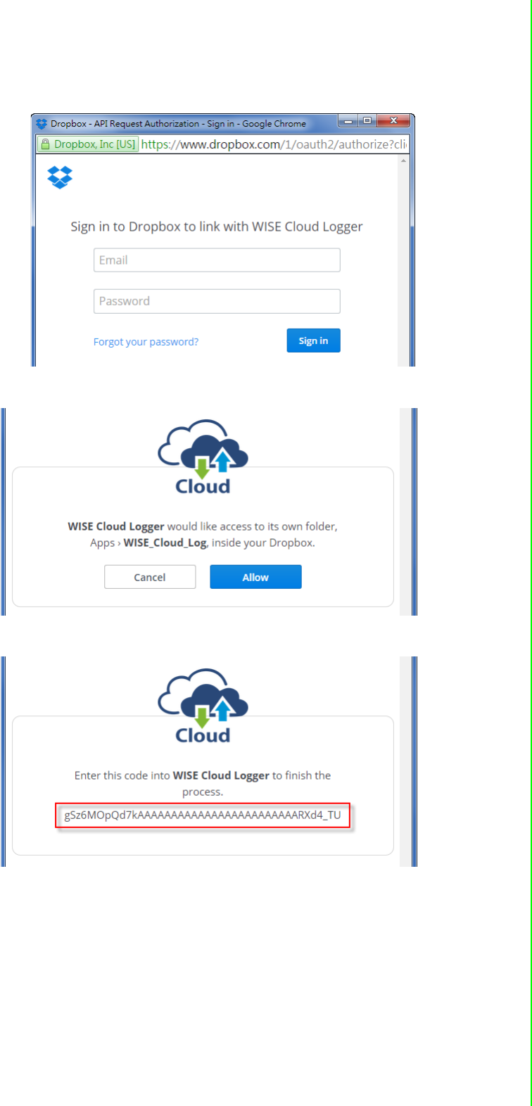
4. The browser will open a new window for Dropbox. Enter your Dropbox account
information including E-mail and Password, then click “Sign in”.
5. After logging in, click "Allow" to allow WISE Cloud Logger Apps to access your
Dropbox account to store the data log file.
6. Dropbox will then provide a code, copy this code and return to the configuration
web page of the WISE module.
7. Click "Next" to enter the code.
IMAGE NOT SUPPLIED BY PM!
WISE-4000 User Manual 60
8. Paste the code provided by WISE Cloud Logger, then click "Submit".
9. If your WISE-4000 module is correctly connected to the Internet, you will be able
to set the functions successfully. Click "Close" to return to Configuration.
10. You will then be able to see the “Link Status” shows “Ready”.

61 WISE-4000 User Manual
Chapter 4 System Configuration
4.3 Configure WISE-4000 with ADAM.NET Utility
ADAM.NET Utility, which is designed with graphical operation interface, is aimed to
offer users directly configure, control WISE-4000 module, and monitor the real-time
status of remote WISE-4000 module via Ethernet or Wireless connection.
To keep you informed with latest update, you also can check it from the following
download link on Advantech website.
http://support.advantech.com.tw/Support/DownloadSRDetail.aspx?SR_ID=1-
2AKUDB
1. Install ADAM.NET Utility in your computer.
(After successfully installation, there will be a shortcut generated on the screen)
2. Double click the shortcut icon, and then you will see the main operation window.
3. Click Search Module icon in Toolbar. You will see all online modules in the left
Module Tree screen and an unconfigured new module, whose default password
is 00000000, will appear on the Others section as below. Now you can define
the network mode of the module in the beginning. After that, you will be able to
perform other settings.
4.3.1 Operation Framework
The operation window mainly contains 4 areas, including Menu, Toolbar, Module
Tree screen and Main Operation screen.
4.3.1.1 Menu
a. File
Open Favorite Group
You can import the favorite configuration group file (.XML) from your computer.
Note!
Before installing ADAM.NET Utility, you need to install .NET
Framework 2.0 or higher version.
System requirement
–Microsoft Windows XP/7
–At least 32 MB RAM
–20 MB of hard disk space available
–VGA color or higher resolution monitor
–Mouse or other pointing devices
–10/100 Mbps or higher Ethernet Card
Note! The default password is 00000000

WISE-4000 User Manual 62
Save Favorite Group
You can save the favorite group configuration group as XML file to your com-
puter.
Auto-Initial Group
If you want to have the same favorite group configuration when you exit
ADAM.NET utility and launch it again, you need to check this option.
Exit
Exit ADAM.NET Utility.

63 WISE-4000 User Manual
Chapter 4 System Configuration
b. Tools
Search Device
Search all the WISE-4000 modules you connected in local Ethernet.
Add Devices to Group
It's used to add WISE-4000 modules to your favorite group. After activating
search function, all online modules will show on Module Tree Screen area. Now
you can enable this function to select the device you want to add in the Module
Tree Screen.
Group Configuration
Group Configuration is on WISE-4000 series module. It can help you efficiently
configure or maintain massive WISE-4000 modules with the same configuration
file or firmware upgrade at one time in the local network. The following steps will
instruct you how to operate it.
Terminal for Command Testing
WISE-4000 series module Modbus/TCP as communication protocol, so you can
launch the terminal to directly communicate with WISE-4000 series module by
these two protocols.
Print Screen
You can save current ADAM.NET Utility screen into an image file by this option.
HTML File Packager
You can pack your user web page by this tool:
1.Put all the files that going to pack in same folder, and “Browse…” the folder
2.Press “Save as…” and give a file name after package
3.Check all the files had been selected in “File List”
4.Check “Gzip Compression” to reduce the file size
5.After press the “Apply” button, your user web page will be compressed as
“*.ehf” file, then you can download the file into your WISE module

WISE-4000 User Manual 64
c. Setup
Favorite Group
You can configure your favorite group including add one new device, modify or
delete one current device, sort current devices and diagnose connection to one
device.
Refresh Serial and Ethernet
ADAM.NET utility will refresh the serial and LAN network connection situation.
Add COM Ports
This option is used to add serial COM ports in ADAM.NET Utility. You won't
need to use this option for WISE-4000 modules.
Show TreeView
Check this option to display the Module Tree Screen area.
Allow Calibration
Check this option to allow calibration function enabled on AI/O module.
d. Help
Check Up-to-Date on the Web
It will automatically connect to support and download page of Advantech web-
site when it enabled. You can find and download the latest version of WISE-
4000 utility there.
About ADAM.NET Utility
The current version of ADAM.NET Utility is installed on your computer.

65 WISE-4000 User Manual
Chapter 4 System Configuration
4.3.1.2 Toolbar
There are 8 graphical icons for common used options of Menu on the toolbar.
Definition (from left to right)
1. Open favorite group
2. Save favorite group
3. Search Modules
4. Add Devices to Group
5. Terminal for Command Testing
6. Group Configuration
7. Monitor Data Stream/Event
8. Print Screen
4.3.1.3 Module Tree Screen
The Module Tree Screen locates on the left part of ADAM.NET utility operation win-
dow. There are four categories in this area:
Serial
All serial I/O Modules (ADAM-4000 and ADAM-5000 RS-485 serial modules) con-
nected to the host PC will be listed in this category.
Ethernet
All Ethernet I/O Modules (WISE-4000, ADAM-6000, ADAM-6100,and ADAM-5000
TCP modules) connected to the host PC will be listed in this category.
Favorite Group
You can define which devices listed in the three categories above into your personal
favorite group. This will make you easier to find your interested modules. Right click
on the WISE-4000 device item under the Favorite Group item and you can select Add
New Group to create a new group. After you create your own group, right click on
your group and Add New Device into your group. You can also select Diagnose con-
nection to check the communication.
ADAM-4500_5510 Series
This is a DOS interface utility for remote controllers such as ADAM-4500 and ADAM-
5510 series.
Wireless Sensor Networks
All wireless I/O Modules (ADAM-2000 modules) connected to the host PC, through
wireless gateway, will be listed in this category.
4.3.1.4 Main Operation Screen
Main Operation Screen located on the right side of utility includes I/O status display
and function setting. You can select different items in Module Tree Screen, and then
Main Operation Screen will change dependently. You can do all configurations and
test in this area.
In Information page (after clicking Ethernet), you can configure Connection/Send/
Receive/Scan Timeout. The supervisor password is a shortcut to let you enter a
password at one time which's applied for certain modules, so you don't need to enter
the same password for each module when you check it.
WISE-4000 User Manual 66
4.3.2 Configure WISE-4000
1. Configure the computer’s IP address as the same domain as WISE-4000 mod-
ule. For the new WISE-4000/LAN Series which default IP address is 10.0.0.1,
the IP address of computer can be configured as 10.0.0.99 for example as fol-
lowing.
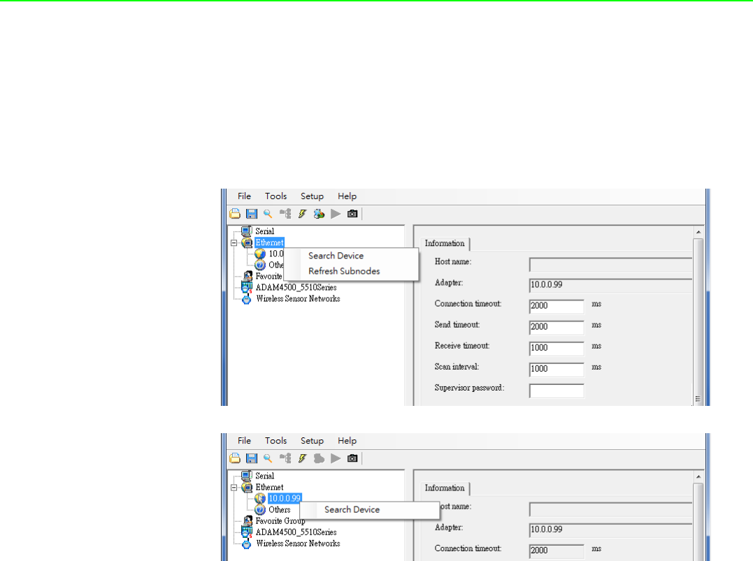
2. Open the Adam/Apax .NET Utility then you can see the IP address of computer
been shown under “Ethernet” tree. You can right click to refresh the subnodes of
this tree. Or click “Search Device” to find WISE-4000 module.
3. Users can also right click the IP address to find WISE-4000 module.
67 WISE-4000 User Manual
Chapter 4 System Configuration
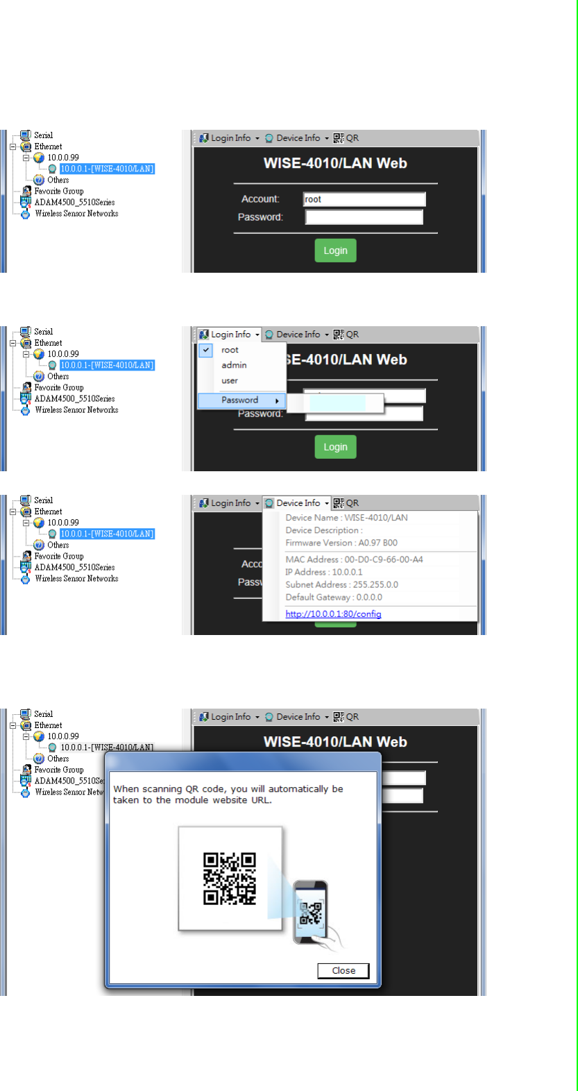
4. After the module been found, it will be listed under IP address in same domain,
you can login the embedded web configuration web page for further configura-
tion as introduced in previous section
5. There are some function provide in same pages in utility, first you can enter the
account and password faster in "Login Info" tab.
6. In the "Device Info" tab, the detail information of this module will been shown
7. The "QR" tab will generate the QR code of the web configuration web page for
mobile device to access the module. User can also click the QR code to open
the browser for further configuration.
WISE-4000 User Manual 68
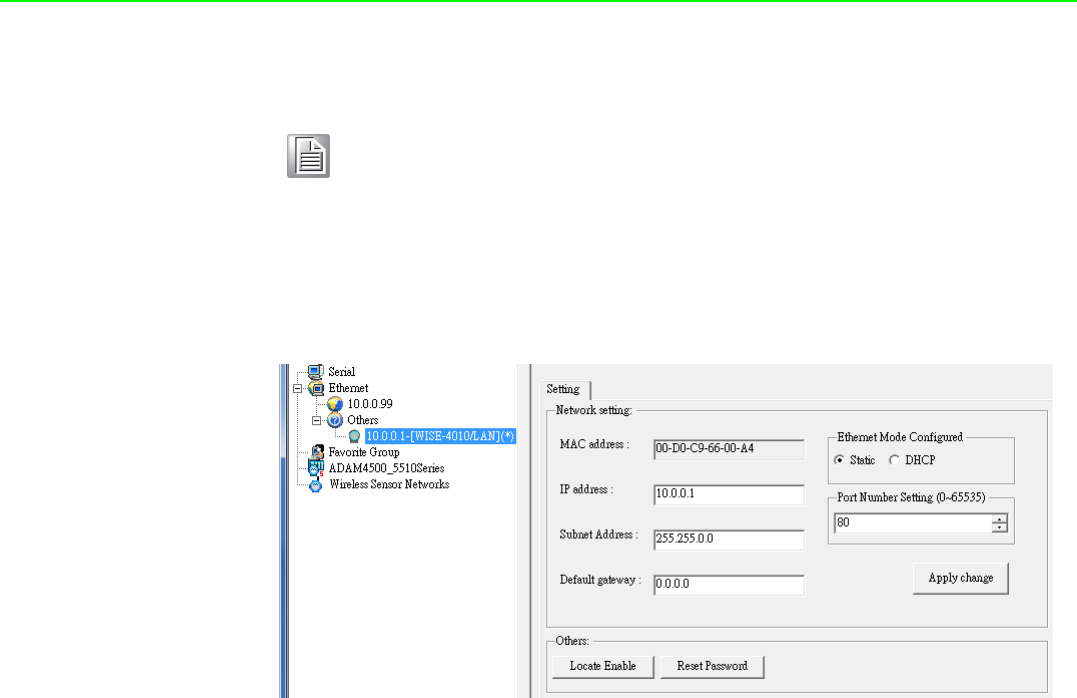
Note! If you are not able to search the module, you can configure the SW1
behind the module to initial mode. After power up and search the mod-
ule in utility, user can find the module with default IP address, and the
device name will been shown in "Others" tree with (*) sign. So user can
change the device network setting in this page. Or try to locate the
device and also reset the password with same page. After the new net-
work setting been apply, please configure the SW1 back to normal
mode and power up again to reboot in new network setting.
69 WISE-4000 User Manual
Chapter 4 System Configuration
4.4 Site Survey Tool for WISE-4000 Wireless Series
WISE-4000 Wireless Series provides Site Survey Tool for testing the communication
quality between WISE-4000 wireless module with wireless access point or wireless
router.
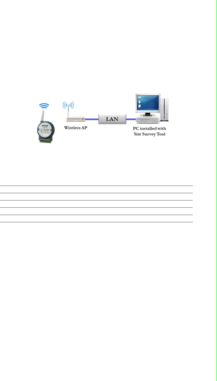
4.4.1 Site Survey Architecture
Wiring the wireless AP with the PC installed with Site Survey Tool (Utility), if possible,
the network should only have PC, AP, and WISE-4000 only.
4.4.2 Site Survey Mode
WISE module will go to site survey mode operation for testing communication quality.
Most of the functions of WISE module will temporally stop to doing site survey opera-
tion. And the LED status will work as following:
LED Color Indication Behavior
Status Green OFF Site Survey mode
Com Yellow Blink Site Survey data packet TX/RX
AP/Infra Green OFF Site Survey mode (Station Mode)
Signal Strength Green Blink Site Survey mode
WISE-4000 User Manual 70
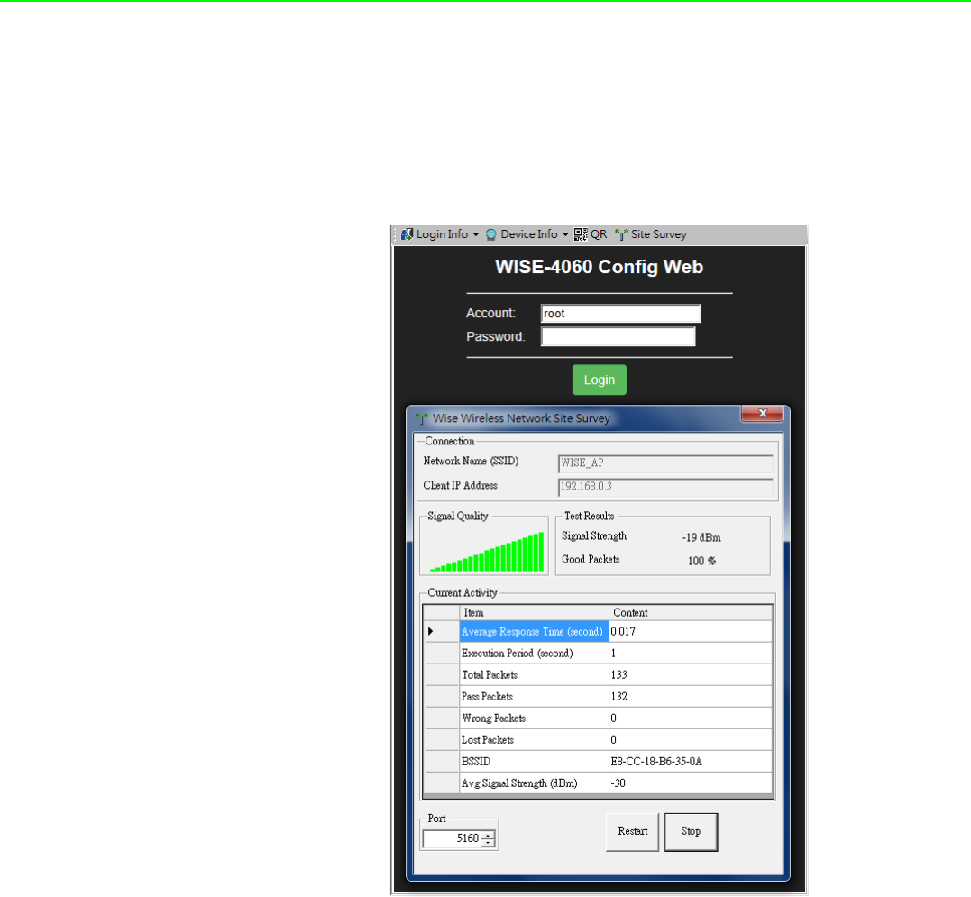
4.4.3 Site Survey Tool
Search WISE-4000 module as described in the last section, after click the module
shown in Ethernet tree. There is a “Site Survey” icon as following. Click the "Site Sur-
vey" icon to open site survey tool windows as following. Click "Start" to set the mod-
ule in site survey mode and start the site survey tool. User can click "Restart" to
restart the testing result, or click "Stop" to stop the testing and set the module back to
normal operation.
Connection
Network Name (SSID): Show which wireless AP is connected.
Client IP Address: Show the IP address of the wireless adapter of PC
Signal Quality
Show the signal strength by bar chart
Testing Results
Signal Strength: The average result of the signal strength during testing
Good Package: The percentage of passed packets during testing
Current Activity
Detail information of each testing packets
Port
User can configure which UDP port of PC is assigned for site survey testing

Appendix A
AI/O Modbus Mapping
Table

WISE-4000 User Manual 72
A.1 Modbus Function Code Introduction
To full-fill the programming requirement, there is a series of function code standard
for user’s reference.
A.2 WISE-4010/LAN Modbus Mapping Table
Address (0X):
Code (Hex) Name Usage
01 Read Coil Status Read Discrete Output Bit
02 Read Input Status Read Discrete Input Bit
03 Read Holding Registers Read 16-bit register. Used to read integer or
floating point process data.
04 Read Input Registers
05 Force Single Coil Write data to force coil ON/OFF
06 Preset Single Register Write data in 16-bit integer format
08 Loopback Diagnosis Diagnostic testing of the communication port
0F Force Multiple Coils Write multiple data to force coil ON/OFF
10 Preset Multiple Registers Write multiple data in 16-bit integer format
Address (0X) Channel Description Attribute
00017 0
DO Value
Read/Write
00018 1 Read/Write
00019 2 Read/Write
00020 3 Read/Write
00101 0
Reset Historical
Maximum AI Value
Write
00102 1 Write
00103 2 Write
00104 3 Write
00105 Average Ch 0~3 Write
00111 0
Reset Historical Min. AI Value
Write
00112 1 Write
00113 2 Write
00114 3 Write
00115 Average Ch 0~3 Write
00121 0
Open-Circuit Flag (Burnout)
Read
00122 1 Read
00123 2 Read
00124 3 Read

73 WISE-4000 User Manual
Appendix A I/O Modbus Mapping Table
Address (4X):
00131 0
High Alarm Flag
Read
00132 1 Read
00133 2 Read
00134 3 Read
00135 Average Ch 0~3 Read
00141 0
Low Alarm Flag
Read
00142 1 Read
00143 2 Read
00144 3 Read
00145 Average Ch 0~3 Read
Address (4X) Channel Description Attribute
40211 Module Name 1 Read
40212 Module Name 2 Read
40221 All AI AI Channel Enabled Read/Write
40303 All DO DO Value Read/Write
40001 0
AI Value
Read
40002 1 Read
40003 2 Read
40004 3 Read
40005 Average Ch 0~3 Read
40009-40010 0
Pulse Output
Low Level Width
Read/Write
40011~40012 1 Read/Write
40013~40014 2 Read/Write
40015~40016 3 Read/Write
40017-40018 0
Pulse Output
High Level Width
Read/Write
40019~40020 1 Read/Write
40021~40022 2 Read/Write
40023~40024 3 Read/Write
40025-40026 0
Set Absolute Pule
Read/Write
40027~40028 1 Read/Write
40029~40030 2 Read/Write
40031~40032 3 Read/Write

WISE-4000 User Manual 74
40033~40034 0
Set Incremental Pulse
Read/Write
40035~40035 1 Read/Write
40037~40038 2 Read/Write
40037~40040 3 Read/Write
40101~40102 0
AI Status*
Read
40103~40104 1 Read
40105~40106 2 Read
40107~40108 3 Read
40111 0
Historical
Maximum AI Value
Read
40112 1 Read
40113 2 Read
40114 3 Read
40115 Average Ch 0~3 Read
40121 0
Historical
Minimum AI Value
Read
40122 1 Read
40123 2 Read
40124 3 Read
40125 Average Ch 0~3 Read
40131~40132 0
AI Floating Value
(IEEE754)
Read
40133~40134 1 Read
40135~40136 2 Read
40137~40138 3 Read
40139~40140 Average Ch 0~3 Read
40151~40152 0
Historical Maximum
AI Floating Value
(IEEE754)
Read
40153~40154 1 Read
40155~40156 2 Read
40157~40158 3 Read
40159~40160 Average Ch 0~3 Read
40171~40172 0
Historical Minimum
AI Floating Value
(IEEE754)
Read
40173~40174 1 Read
40175~40176 2 Read
40177~40178 3 Read
40179~40180 Average Ch 0~3 Read
40191 0
AI Value
After Scaling
Read
40192 1 Read
40193 2 Read
40194 3 Read
40195 Average Ch 0~3 Read

75 WISE-4000 User Manual
Appendix A I/O Modbus Mapping Table
40201 0
AI Type Code**
(The type codes of channels for
average value can't be changed.)
Read/Write
40202 1 Read/Write
40203 2 Read/Write
40204 3 Read/Write
40205 Average Ch 0~3 Read
* AI Status (2 Registers)
Lower Register Higher Register
Bit Description Bit Description
0 Fail to Provide AI Value 0 DI triggered to Safety Value
1 Over Range 1 DI triggered to Startup Value
2 Under Range 2 Reserved
3 Open Circuit / Burnout 3 Reserved
4 Reserved 4 Reserved
5 Reserved 5 Reserved
6 Reserved 6 Reserved
7 ADC Initializing/Error 7 Reserved
8 Reserved 8 Reserved
9 Zero/Span Calibration Error 9 Reserved
10 Reserved 10 Reserved
11 Reserved 11 Reserved
12 Reserved 12 Reserved
13 Reserved 13 Reserved
14 Reserved 14 Reserved
15 Reserved 15 Reserved
** AI Type Code (2 Registers)
Type Code Input Range
0x1080 4~20 mA
0x1082 0~20 mA

WISE-4000 User Manual 76
A.3 WISE-4050/LAN Modbus Mapping Table
Address 0X Channel Description Attribute
00001 0
DI Value
Read
00002 1 Read
00003 2 Read
00004 3 Read
00017 0
DO Value
Read/Write
00018 1 Read/Write
00019 2 Read/Write
00020 3 Read/Write
00033 0
Counter Status
(0: stop
1: start)
Read/Write
00034 1 Read/Write
00035 2 Read/Write
00036 3 Read/Write
00037 0
Clear Counter
(1: write to clear value)
Write
00038 1 Write
00039 2 Write
00040 3 Write
00041 0
Clear Overflow
(1: counter overflow,
auto set to 0 after read)
Read/Write
00042 1 Read/Write
00043 2 Read/Write
00044 3 Read/Write
00045 0
DI Latch Status
(1: DI latched,
0: write to clear latch)
Read/Write
00046 1 Read/Write
00047 2 Read/Write
00048 3 Read/Write
Address 4X Channel Description Attribute
40211 - Module Name 1 Read
40212 - Module Name 2 Read
40301 All DI DI Value Read
40303 All DO DO Value Read/Write
40001~40002 0
Counter/Frequency
Value
Read
40003~40004 1 Read
40005~40006 2 Read
40007~40008 3 Read

77 WISE-4000 User Manual
Appendix A I/O Modbus Mapping Table
40009~40010 0
Pulse Output
Low Level Width
Read/Write
40011~40012 1 Read/Write
40013~40014 2 Read/Write
40015~40016 3 Read/Write
40017~40018 0
Pulse Output
High Level Width
Read/Write
40019~40020 1 Read/Write
40021~40022 2 Read/Write
40023~40024 3 Read/Write
40025~40026 0
Set Absolute
Pulse Output Number
Read/Write
40027~40028 1 Read/Write
40029~40030 2 Read/Write
40031~40032 3 Read/Write
40033~40034 0
Set Incremental
Pulse Output Number
Read/Write
40035~40036 1 Read/Write
40037~40038 2 Read/Write
40039~40040 3 Read/Write

WISE-4000 User Manual 78
A.4 WISE-4060/LAN Modbus Mapping Table
Address 0X Channel Description Attribute
00001 0
DI Value
Read
00002 1 Read
00003 2 Read
00004 3 Read
00017 0
DO Value
Read/Write
00018 1 Read/Write
00019 2 Read/Write
00020 3 Read/Write
00033 0
Counter Status
(0: stop
1: start)
Read/Write
00034 1 Read/Write
00035 2 Read/Write
00036 3 Read/Write
00037 0
Clear Counter
(1: write to clear value)
Write
00038 1 Write
00039 2 Write
00040 3 Write
00041 0
Clear Overflow
(1: counter overflow,
auto set to 0 after read)
Read/Write
00042 1 Read/Write
00043 2 Read/Write
00044 3 Read/Write
00045 0
DI Latch Status
(1: DI latched,
0: write to clear latch)
Read/Write
00046 1 Read/Write
00047 2 Read/Write
00048 3 Read/Write
Address 4X Channel Description Attribute
40211 - Module Name 1 Read
40212 - Module Name 2 Read
40301 All DI DI Value Read
40303 All DO DO Value Read/Write
40001~40002 0
Counter/Frequency
Value
Read
40003~40004 1 Read
40005~40006 2 Read
40007~40008 3 Read

79 WISE-4000 User Manual
Appendix A I/O Modbus Mapping Table
40009~40010 0
Pulse Output
Low Level Width
Read/Write
40011~40012 1 Read/Write
40013~40014 2 Read/Write
40015~40016 3 Read/Write
40017~40018 0
Pulse Output
High Level Width
Read/Write
40019~40020 1 Read/Write
40021~40022 2 Read/Write
40023~40024 3 Read/Write
40025~40026 0
Set Absolute
Pulse Output Number
Read/Write
40027~40028 1 Read/Write
40029~40030 2 Read/Write
40031~40032 3 Read/Write
40033~40034 0
Set Incremental
Pulse Output Number
Read/Write
40035~40036 1 Read/Write
40037~40038 2 Read/Write
40039~40040 3 Read/Write

WISE-4000 User Manual 80
A.5 WISE-4012E Wireless Modbus Mapping Table
Address 0X Channel Description Attribute
00001 0 DI Value Read
00002 1 Read
00017 0 DO Value R/W
00018 1 R/W
00033 0 Counter Status
(0: stop
1: start)
R/W
00034 1 R/W
00035 0 Clear Counter
(1: write to clear value)
Write
00036 1 Write
00037 0 Clear Overflow
(1: counter overflow,
auto set to 0 after read)
R/W
00038 1 R/W
00039 0 DI Latch Status
(1: DI latched,
0: write to clear latch)
R/W
00040 1 R/W
00101 0
Reset Historical
Maximum AI Value
Write
00102 1 Write
00103 Average
Channel 0~1 Write
00111 0
Reset Historical
Minimum AI Value
Write
00112 1 Write
00113 Average
Channel 0~1 Write
00131 0
High Alarm Flag
Read
00132 1 Read
00133 Average
Channel 0~1 Read
00141 0
Low Alarm Flag
Read
00142 1 Read
00143 Average
Channel 0~1 Read
Address 4X Channel Description Attribute
40211 Module Name 1 Read
40212 Module Name 2 Read
40221 All AI AI Channel Enable R/W

81 WISE-4000 User Manual
Appendix A I/O Modbus Mapping Table
40301 All DI DI Value Read
40303 All DO DO Value R/W
40001 0 AI Value
(Value Range: 0~10000,
Value Unit: mV)
Read
40002 1 Read
40003 Average
Channel 0~1 Read
40017~40018 0 Counter/Frequency
Value
R/W
40019~40020 1 R/W
40021~40022 0 Pulse Output
Low Level Width
R/W
40023~40024 1 R/W
40025~40026 0 Pulse Output
High Level Width
R/W
40027~40028 1 R/W
40029~40030 0 Set Absolute Pulse R/W
40031~40032 1 R/W
40033~40034 0 Set Incremental Pulse R/W
40035~40036 1 R/W
40101~40102 0 AI Status* Read
40103~40104 1 Read
40111 0
Historical
Maximum AI Value
Read
40112 1 Read
40113 Average
Channel 0~1 Read
40121 0
Historical
Minimum AI Value
Read
40122 1 Read
40123 Average
Channel 0~1 Read
40131~40132 0
AI Floating Value
(IEEE754)
Read
40133~40134 1 Read
40135~40136 Average
Channel 0~1 Read
40151~40152 0 Historical Maximum
AI Floating Value
(IEEE754)
Read
40153~40154 1 Read
40155~40156 Average
Channel 0~1 Read

WISE-4000 User Manual 82
40171~40172 0 Historical Minimum
AI Floating Value
(IEEE754)
Read
40173~40174 1 Read
40175~40176 Average
Channel 0~1 Read
40191 0
AI Value
After Scaling
Read
40192 1 Read
40193 Average
Channel 0~1 Read
40201 0 AI Type Code**
(The type codes of channels for average
value can't be changed.)
R/W
40202 1 R/W
40203 Average
Channel 0~1 R
* AI Status (2 Registers)
Lower Register Higher Register
Bit Description Bit Description
0 Fail to Provide AI Value 0 DI triggered to Safety Value
1 Over Range 1 DI triggered to Startup Value
2 Under Range 2 Reserved
3 Open Circuit / Burnout 3 Reserved
4 Reserved 4 Reserved
5 Reserved 5 Reserved
6 Reserved 6 Reserved
7 ADC Initializing/Error 7 Reserved
8 Reserved 8 Reserved
9 Zero/Span Calibration Error 9 Reserved
10 Reserved 10 Reserved
11 Reserved 11 Reserved
12 Reserved 12 Reserved
13 Reserved 13 Reserved
14 Reserved 14 Reserved
15 Reserved 15 Reserved
** AI Type Code (2 Registers)
Type Code Input Range
0x0148 0~10 V

83 WISE-4000 User Manual
Appendix A I/O Modbus Mapping Table
A.6 WISE-4050 Wireless Modbus Mapping Table
Address 0X Channel Description Attribute
00001 0
DI Value
Read
00002 1 Read
00003 2 Read
00004 3 Read
00017 0
DO Value
R/W
00018 1 R/W
00019 2 R/W
00020 3 R/W
00033 0
Counter Status
(0: stop
1: start)
R/W
00034 1 R/W
00035 2 R/W
00036 3 R/W
00037 0
Clear Counter
(1: write to clear value)
Write
00038 1 Write
00039 2 Write
00040 3 Write
00041 0
Clear Overflow
(1: counter overflow,
auto set to 0 after read)
R/W
00042 1 R/W
00043 2 R/W
00044 3 R/W
00045 0
DI Latch Status
(1: DI latched,
0: write to clear latch)
R/W
00046 1 R/W
00047 2 R/W
00048 3 R/W
Address 4X Channel Description Attribute
40211 - Module Name 1 Read
40212 - Module Name 2 Read
40301 All DI DI Value Read
40303 All DO DO Value R/W
40001~40002 0
Counter/Frequency
Value
Read
40003~40004 1 Read
40005~40006 2 Read
40007~40008 3 Read

WISE-4000 User Manual 84
40009~40010 0
Pulse Output
Low Level Width
R/W
40011~40012 1 R/W
40013~40014 2 R/W
40015~40016 3 R/W
40017~40018 0
Pulse Output
High Level Width
R/W
40019~40020 1 R/W
40021~40022 2 R/W
40023~40024 3 R/W
40025~40026 0
Set Absolute
Pulse Output Number
R/W
40027~40028 1 R/W
40029~40030 2 R/W
40031~40032 3 R/W
40033~40034 0
Set Incremental
Pulse Output Number
R/W
40035~40036 1 R/W
40037~40038 2 R/W
40039~40040 3 R/W

85 WISE-4000 User Manual
Appendix A I/O Modbus Mapping Table
A.7 WISE-4060 Wireless Modbus Mapping Table
Address 0X Channel Description Attribute
00001 0
DI Value
Read
00002 1 Read
00003 2 Read
00004 3 Read
00017 0
DO Value
R/W
00018 1 R/W
00019 2 R/W
00020 3 R/W
00033 0
Counter Status
(0: stop
1: start)
R/W
00034 1 R/W
00035 2 R/W
00036 3 R/W
00037 0
Clear Counter
(1: write to clear value)
Write
00038 1 Write
00039 2 Write
00040 3 Write
00041 0
Clear Overflow
(1: counter overflow,
auto set to 0 after read)
R/W
00042 1 R/W
00043 2 R/W
00044 3 R/W
00045 0
DI Latch Status
(1: DI latched,
0: write to clear latch)
R/W
00046 1 R/W
00047 2 R/W
00048 3 R/W
Address 4X Channel Description Attribute
40211 - Module Name 1 Read
40212 - Module Name 2 Read
40301 All DI DI Value Read
40303 All DO DO Value R/W
40001~40002 0
Counter/Frequency
Value
Read
40003~40004 1 Read
40005~40006 2 Read
40007~40008 3 Read

WISE-4000 User Manual 86
40009~40010 0
Pulse Output
Low Level Width
R/W
40011~40012 1 R/W
40013~40014 2 R/W
40015~40016 3 R/W
40017~40018 0
Pulse Output
High Level Width
R/W
40019~40020 1 R/W
40021~40022 2 R/W
40023~40024 3 R/W
40025~40026 0
Set Absolute
Pulse Output Number
R/W
40027~40028 1 R/W
40029~40030 2 R/W
40031~40032 3 R/W
40033~40034 0
Set Incremental
Pulse Output Number
R/W
40035~40036 1 R/W
40037~40038 2 R/W
40039~40040 3 R/W

Appendix B
BREST for WISE-4000
Series

WISE-4000 User Manual 88
B.1 Introduction
REpresentational State Transfer (REST) is a design style of software architecture for
Web application behaves and services including image indication, resource request
and response and message delivery. It can be developed compatible with popular
protocols or standards like HTTP, URI, JSON, HTML. With the advantage of scalabil-
ity, simplicity and performance, it's already adopted in Web service by Amazon,
Yahoo. The Web service of is developed based on HTML5 language, if user need to
integrate this into other Web services, the following information/command list should
be referred for implementation.

89 WISE-4000 User Manual
Appendix B REST for WISE-4000 Series
B.2 REST Resources for WISE-4000 Series
B.2.1 Digital Input
B.2.1.1 /di_value/slot_index/ch_num
Description Retrieves information about the digital input value resource on specific slot.
URL Structure http://10.0.0.1/di_value/slot_index
http://10.0.0.1/di_value/slot_index/ch_num
HTTP Method
GET:Returns the representation of all of digital input value resource.
PUT:Replace all of digital input value resource
PATCH:Apply partial modifications to digital input value resource.

WISE-4000 User Manual 90
GET
Multiple Channel Request:
GET /di_value/slot_index
Single Channel Request:
GET /di_value/slot_index/ch_num
[Example]
Request: GET /di_value/slot_0
Content-type: application/json
Response: 200 OK
{
"DIVal": [
{
"Ch":0,
"Md":0,
"Stat":1,
"Val":1,
"Cnting":0,
"ClrCnt":0,
"OvLch": 0
},
{
"Ch":1,
"Md":0,
"Stat":0,
"Val":0,
"Cnting":0,
"ClrCnt":0,
"OvLch": 0
},
{
"Ch":2,
"Md":1,
"Stat":0,
"Val":3378,
"Cnting":1,
"ClrCnt":0,
"OvLch": 0
},
{
"Ch":3,
"Md":3,
"Stat":0,
"Val":1,
"Cnting":0,
"ClrCnt":0,
"OvLch": 0
}
]
}
Request : GET /di_value/slot_0/ch_2
Content-type: application/json
Response: 200 OK
{
"Ch":2,
"Md":0,
"Stat":1,
"Val":1,
"Cnting":0,
"ClrCnt":0,
"OvLch": 0
}

91 WISE-4000 User Manual
Appendix B REST for WISE-4000 Series
PUT
Single/Multiple Channel Request:
PUT /di_value/slot_index
Single Channel Request:
PUT /di_value/slot_index/ch_num
[Example]
Request: PUT /di_value/slot_0
Content-type: application/json
{
"DIVal": [
{
"Ch":0,
"Md":0,
"Stat":0,
"Val":0,
"Cnting":0,
"ClrCnt":0,
"OvLch": 0
},
{
"Ch":1,
"Md":0,
"Stat":0,
"Val":0,
"Cnting":0,
"ClrCnt":0,
"OvLch": 0
},
{
"Ch":2,
"Md":1,
"Stat":0,
"Val":3378,
"Cnting":0,
"ClrCnt":1,
"OvLch": 0
},
{
"Ch":3,
"Md":3,
"Stat":0,
"Val":0,
"Cnting":0,
"ClrCnt":0,
"OvLch": 0
}
]
}
Response: 200 OK
Request: PUT /di_value/slot_0/ch_2
Content-type: application/json
{
"Ch":2,
"Md":1,
"Stat":0,
"Val":3378,
"Cnting":0,
"ClrCnt":1,
"OvLch": 0
}
Response: 200 OK

WISE-4000 User Manual 92
JSON array name definition:
PATCH
Single/Multiple Channel Request:
PATCH /di_value/slot_index
Single Channel Request:
PATCH /di_value/slot_index/ch_num
[Example]
Request: PATCH /di_value/slot_0
Content-type: application/json
{
"DIVal": [
{
"Ch":2,
"Cnting": 1
},
{
"Ch":3,
"OvLch":0
}
]
}
Response: 200 OK
Request: PATCH /di_value/slot_0/ch_3
Content-type: application/json
{
"Ch":3,
"ClrCnt":1
}
Response: 200 OK
Field Abbreviation Data Type
Array of Digital input configurations DIVal Array

93 WISE-4000 User Manual
Appendix B REST for WISE-4000 Series
Resource value definitions:
Field Abbreviation Data Type Property Description
Channel Number Ch Number R 0, 1, …: Digital input channel number.
Mode Md Number R
Digital input mode.
Signal Logic Status Stat Number R 1, 0: Input signal is Logic High or Low.
Channel Value Val Number R
DI measurement data
Start Counter Cnting Number RW
Start/Stop counter counting
Read
1 : counter is counting
0 : not counting
Write
1 : start counting
0 : stop counting
Clear Counter ClrCnt Number W 1 : Clear the counter value
Get/Clear Counter
Overflow or Latch Sta-
tus
OvLch Number RW
counter overflow or latch status
Read
1 : overflow/latch occurred.
0 : no overflow or latch
Write
0 : clear the overflow or latch status
0DI
1 Counter
2 LowToHighLatch
3 HighToLowLatch
4 Frequency
Input Mode Value Description
DI Logic Status of DI
Counter Counter Value
LowToHighLatch Logic status of DI
HighToLowLatch Logic status of DI
Frequency Frequency(unity 0.1 Hz

WISE-4000 User Manual 94
B.2.2 Digital Output
B.2.2.1 /do_value/slot_index/ch_num
Description Retrieves information about the digital output value resource on specific slot.
URL Structure http://10.0.0.1/do_value/slot_index
http://10.0.0.1/do_value/slot_index/ch_num
HTTP Method
GET:Returns the representation of all of digital output value resource.
PUT:Replace all of digital output value resource
PATCH:Apply partial modifications to digital output value resource.

95 WISE-4000 User Manual
Appendix B REST for WISE-4000 Series
GET
Multiple Channel Request:
GET /do_value/slot_index
Single Channel Request:
GET /do_value/slot_index/ch_num
[Example]
Request: GET /do_value/slot_0
Content-type: application/json
Response: 200 OK
{
"DOVal": [
{
"Ch":0,
"Md":0,
"Stat":1,
"Val":1,
"PsCtn":0,
"PsStop":0,
"PsIV": 0
},
{
"Ch":1,
"Md":0,
"Stat":0,
"Val":0,
"PsCtn":0,
"PsStop":0,
"PsIV": 0
},
{
"Ch":2,
"Md":1,
"Stat":1,
"Val":3378,
"PsCtn":0,
"PsStop":0,
"PsIV": 0
},
{
"Ch":3,
"Md":3,
"Stat":1,
"Val":1,
"PsCtn":0,
"PsStop":0,
"PsIV": 0
}
]
}
Request : GET /do_value/slot_0/ch_2
Content-type: application/json
Response: 200 OK
{
"Ch":2,
"Md":0,
"Stat":1,
"Val":1,
"PsCtn":0,
"PsStop":0,
"PsIV": 0
}

WISE-4000 User Manual 96
PUT
Single/Multiple Channel Request:
PUT /do_value/slot_index
Single Channel Request:
PUT /do_value/slot_index/ch_num
[Example]
Request: PUT /do_value/slot_0
Content-type: application/json
{
"DOVal": [
{
"Ch":0,
"Md":0,
"Stat":1,
"Val":1,
"PsCtn":0,
"PsStop":0,
"PsIV": 0
},
{
"Ch":1,
"Md":0,
"Stat":0,
"Val":0,
"PsCtn":0,
"PsStop":0,
"PsIV": 0
},
{
"Ch":2,
"Md":1,
"Stat":1,
"Val":3378,
"PsCtn":0,
"PsStop":0,
"PsIV": 0
},
{
"Ch":3,
"Md":3,
"Stat":1,
"Val":1,
"PsCtn":0,
"PsStop":0,
"PsIV": 0
}
]
}
Response: 200 OK
Request: PUT /do_value/slot_0/ch_2
Content-type: application/json
{
"Ch":2,
"Md":2,
"Stat":0,
"Val":0,
"PsCtn":0,
"PsStop":0,
"PsIV": 0
}
Response: 200 OK

97 WISE-4000 User Manual
Appendix B REST for WISE-4000 Series
JSON array name definition:
PATCH
Single/Multiple Channel Request:
PATCH /do_value/slot_index
Single Channel Request:
PATCH /do_value/slot_index/ch_num
[Example]
Request: PATCH /do_value/slot_0
Content-type: application/json
{
"DOVal": [
{
"Ch":2,
"Md": 2
},
{
"Ch":3,
"PsStop":1
}
]
}
Response: 200 OK
Request: PATCH /do_value/slot_0/ch_3
Content-type: application/json
{
"Ch":3,
"PsCtn":1
}
Response: 200 OK
Field Abbreviation Data Type
Array of Digital input
configurations DOVal Array

WISE-4000 User Manual 98
Resource value definitions:
Field Abbreviation Data Type Property Description
Channel Number Ch Number R 0, 1, …: Digital output channel number.
Mode Md Number R
Digital output mode.
Signal Logic Status Stat Number R 1, 0: Output signal is Logic High or Low.
Channel Value Val Number RW
DO measurement data
Output Mode
Value Description
DO
Get the current signal status or set its status
Pulse Output
Get or set the absolute pulse count value
LowToHighDelay
Get the current signal status or set its status
HighToLowDelay
Get the current signal status or set its status
Pulse Output Continue
State PsCtn Number RW 1 / 0: Pulse outputting is continuous or not.
Stop Pulse Output PsStop Number W
1: Stop the pulse outputting.
(Continue is disabled, Absolute and incremental
values are reset to zero. DO signal status is set to
logic low.)
Incremental Pulse Out-
put Value PsIV Number RW Incremental Pulse Output Value
0DO
1 Pulse Output
2 LowToHighDelay
3 HighToLowDelay

99 WISE-4000 User Manual
Appendix B REST for WISE-4000 Series
B.2.3 Analog Input
B.2.3.1 /ai_value/slot_index/ch_num
Description Retrieves information about the analog input value resource on specific slot.
URL Structure http://10.0.0.1/ai_value/slot_index
http://10.0.0.1/ai_value/slot_index/ch_num
HTTP Method
GET:Returns the representation of all of analog input value resource.
PUT:None
PATCH:Apply partial modifications to analog input value resource.

WISE-4000 User Manual 100
GET
Multiple Channel Request:
GET /ai_value/slot_index
Single Channel Request:
GET /ai_value/slot_index/ch_num
[Example]
Request : GET /ai_value/slot_0
Content-type: application/json
Response: 200 OK
{
"AIVal": [
{
"Ch":0,
"En":1,
"Rng":328,
"Val":148,
"Eg":650,
"Evt":0,
"LoA": 0,
"HiA": 0,
"HVal":190,
"HEg":1250,
"LVal":15,
"LEg":500,
"SVal":148,
"ClrH": 0,
"ClrL": 0
},
{
"Ch":1,
"En":1,
"Rng":328,
"Val":0,
"Eg":0,
"Evt":0,
"LoA":0,
"HiA":0,
"HVal":0,
"HEg":0,
"LVal":0,
"LEg":0,
"SVal":0,
"ClrH": 0,
"ClrL": 0
},
{
"Ch":2,
"En":1,

101 WISE-4000 User Manual
Appendix B REST for WISE-4000 Series
"Rng":328,
"Val":0,
"Eg":0,
"Evt":8,
"LoA":0,
"HiA":0,
"HVal":0,
"HEg":0,
"LVal":0,
"LEg":0,
"SVal":0,
"ClrH": 0,
"ClrL": 0
},
{
"Ch":3,
"En":1,
"Rng":328,
"Val":0,
"Eg":0,
"Evt":0,
"LoA":0,
"HiA":0,
"HVal":0,
"HEg":0,
"LVal":0,
"LEg":0,
"SVal":0,
"ClrH": 0,
"ClrL": 0
},
{
"Ch":4,
"En":1,
"Rng":328,
"Val":0,
"Eg":0,
"Evt":0,
"LoA":0,
"HiA":0,
"HVal":0,
"HEg":0,
"LVal":0,
"LEg":0,
"SVal":0,
"ClrH": 0,
"ClrL": 0
}
]
}
Request : GET /ai_value/slot_0/ch_2
Content-type: application/json
Response: 200 OK
{
"Ch":2,
"En":1,
"Rng":328,
"Val":0,
"Eg":0,
"Evt":8,
"LoA":0,
"HiA":0,
"HVal":0,
"HEg":0,
"LVal":0,
"LEg":0,
"SVal":0,
"ClrH": 0,
"ClrL": 0
}
PUT None

WISE-4000 User Manual 102
JSON array name definition:
PATCH
Single/Multi Channel Request:
PATCH /ai_value/slot_index
Single Channel Request:
PATCH /ai_value/slot_index/ch_num
[Example]
Request: PATCH /ai_value/slot_0
Content-type: application/json
{
"AIVal": [
{
"Ch":2,
"LoA": 0
},
{
"Ch":3,
"HiA":0
}
]
}
Response: 200 OK
Request: PATCH /ai_value/slot_0/ch_3
Content-type: application/json
{
"LoA":0
}
Response: 200 OK
Field Abbreviation Data Type
Array of Analog input
configurations AIVal Array

103 WISE-4000 User Manual
Appendix B REST for WISE-4000 Series
Resource value definitions (Total channels = AI channel number + 1 average
channel):
Field Abbreviation Data Type Property Description
Channel Number Ch Number R
0, 1, …: Analog input channel
number.
Note for the average channel:
The average channel number for a 4-ch AI
module is 4.
Input Range Rng Number R
Analog input range.
Channel Enable En Number R
1 / 0: Enable / Disable AI conversion
Notice: Average channel is read only. When
channel mask of average is not 0, the value
is 1.
Channel Raw
Value Val Number R 0 ~ 65535:AI measurement data (Raw data)
Channel Engi-
neering data Eg Number R
AI engineering data, the value is 1/1000
scale.
For example,
1630 1.63
Channel Event
Status Evt Number R AI statuses
Low Alarm Status LoA Number RW
Low alarm status
Read
1 : low alarm occurred.
0 : not occurred
Write
0 : clear the low alarm status
High Alarm Status HiA Number RW
High alarm status
Read
1 : high alarm occurred.
0 : not occurred
Write
0 : clear the high alarm status
Maximum AI
Raw Value HVal Number R AI max. measurement data (Raw data)
Range code
328 (0x0148) 0 – 10 V
259 (0x0103) +/- 150 mV
260 (0x0104) +/- 500 mV
320 (0x0140) +/- 1 V
321 (0x0141) +/- 2.5 V
322 (0x0142) +/- 5 V
323 (0x0143) +/- 10 V
327 (0x0147) 0 ~ 5 V
384 (0x0180) 4 ~ 20 mA
385 (0x0181) +/- 20 mA
386 (0x0182) 0 ~ 20 mA
65535 Invalid range, if ave
channel is disable

WISE-4000 User Manual 104
Maximum AI
Engineering data HEg Number R
AI max. engineering data, the value is 1/1000
scale
For example,
1020010.2
Minimum AI
Raw Value LVal Number R AI min. measurement data (Raw data)
Minimum AI
Engineering data LEg Number R
AI min. engineering data, the value is 1/1000
scale
For example,
250 0.25
Channel Raw
Value After Scal-
ing
SVal Number R 0 ~ 65535 : AI measurement data (Raw data)
after scaling
Clear Maximum
AI Value ClrH Number W 1 : Clear the Maximum AI value
Clear Minimum
AI Value ClrL Number W 1 : Clear the Minimum AI value
* AI Status (2 Registers)
Lower Register Higher Register
Bit Description Bit Description
0 Fail to Provide AI Value 0 DI triggered to Safety Value
1 Over Range 1 DI triggered to Startup Value
2 Under Range 2 Reserved
3 Open Circuit / Burnout 3 Reserved
4 Reserved 4 Reserved
5 Reserved 5 Reserved
6 Reserved 6 Reserved
7 ADC Initializing/Error 7 Reserved
8 Reserved 8 Reserved
9 Zero/Span Calibration Error 9 Reserved
10 Reserved 10 Reserved
11 Reserved 11 Reserved
12 Reserved 12 Reserved
13 Reserved 13 Reserved
14 Reserved 14 Reserved
15 Reserved 15 Reserved

105 WISE-4000 User Manual
Appendix B REST for WISE-4000 Series
B.2.4 Data Logger
B.2.4.1 /log_message
Description Retrieves the log data in system memory.
URL Structure http://10.0.0.1/log_message
HTTP Method GET: According to the setting of filtering, server returns the all/partial of logged
data.
GET
Request:
GET /log_message
[Example]:
Request: GET /log_message for WISE-4060/LAN module
Content-type: application/json
Response: 200 OK
{
"LogMsg": [
{
"PE":128,
"TIM":"2014-11-11T15:48:32+08:00",
"UID":"ADAM-T160_00D0C9FE1601",
"MAC":"00-D0-C9-FE-16-01",
"Record" :
[
[0,3,3,1],
[0,2,4,150],
[0,5,5,250]
]
},
{
"PE":128,
"TIM":"2014-11-11T15:49:44+08:00",
"UID":"ADAM-T160_00D0C9FE1601",
"MAC":"00-D0-C9-FE-16-01",
"Record" :
[
[0,3,3,0],
[0,2,4,140],
[0,5,5,240]
]
},
{
"PE":128,
"TIM":"2014-11-11T15:51:02+08:00",
"UID":"ADAM-T160_00D0C9FE1601",
"MAC":"00-D0-C9-FE-16-01",
"Record" :
[
[0,3,3,0],
[0,2,4,130],
[0,5,5,230]
]
}
]
}

WISE-4000 User Manual 106
JSON array name definition:
Resource value definitions:
Remarks
Field Abbreviation Data Type
Array of log messages LogMsg Array
Array of I/O records Record Array
Field Abbreviations Data type Property Description
Periodic/Event 128 Number R
Recording mode of storage
Timestamp TIM String R
Timestamp of the storage
“Coordinated Universal Time (UTC)
Ex. “1415757750” corresponds to November 12, 2014,
2:02:30 am, Standard Time.
(meanwhile, 2014, 10:02:30 am, Taipei Time.)
“Local Date/Time according GMT time zone (ISO 8601)
Ex. “1994-11-05T08:15:30-05:00” corresponds to Novem-
ber 5, 1994, 8:15:30 am, US Eastern Standard Time.
UUID UID String R Universally Unique Identifier (UUID)
Max. 32 characters
MAC ID MAC String R MAC address.
(12+5) characters, ex, “00-D0-C9-F0-63-F7
Recording
message Record Array R
* The information in array is as follows.
[Slot-index, Channel-index, I/O-type-index, I/O-value]
* The data type in array is as follows.
[Number, Number, Number, Number]
Notice: When the I/O-type-index is engineering type (12, 13,
14, 18), the I/O value is 1/1000 scale.
1
Event from
DI
2DO
4AI
8AO
16 WDT
128 Periodic
Index Recording I/O-type of the storage
0Invalid
1DI Logic Status
2DI Counter value
3DI Frequency value
4DO Logic Status
5DO Absolute Pulse Output value
6DO Incremental Pulse Output Value
7AI value
8Historical Maximum AI value
9Historical Minimum AI value
10 AI value after scaling
11 AI status flags
12 AI engineering value
13 Historical Maximum AI engineering value
14 Historical Minimum AI engineering value
15 AO value
16 AO value after scaling
17 AO status flags
18 AO engineering value

107 WISE-4000 User Manual
Appendix B REST for WISE-4000 Series

www.advantech.com
Please verify specifications before quoting. This guide is intended for reference
purposes only.
All product specifications are subject to change without notice.
No part of this publication may be reproduced in any form or by any means,
electronic, photocopying, recording or otherwise, without prior written permis-
sion of the publisher.
All brand and product names are trademarks or registered trademarks of their
respective companies.
© Advantech Co., Ltd. 2015
Federal Communication Commission Interference Statement
This equipment has been tested and found to comply with the limits for a Class B
digital device, pursuant to Part 15 of the FCC Rules. These limits are designed to
provide reasonable protection against harmful interference in a residential installation.
This equipment generates, uses and can radiate radio frequency energy and, if not
installed and used in accordance with the instructions, may cause harmful interference
to radio communications. However, there is no guarantee that interference will not
occur in a particular installation. If this equipment does cause harmful interference
to radio or television reception, which can be determined by turning the equipment off
and on, the user is encouraged to try to correct the interference by one of the
following measures:
z Reorient or relocate the receiving antenna.
z Increase the separation between the equipment and receiver.
z Connect the equipment into an outlet on a circuit different from that to which
the receiver is connected.
z Consult the dealer or an experienced radio/TV technician for help.
15.21 警語
FCC Caution: Any changes or modifications not expressly approved by the party
responsible for compliance could void the user's authority to operate this equipment.
FCC RF Radiation Exposure Statement:
1. This Transmitter must not be co-located or operating in conjunction with any other
antenna or transmitter.
2. This equipment complies with FCC RF radiation exposure limits set forth for an
uncontrolled environment. This equipment should be installed and operated with a
minimum distance of 20 centimeters between the radiator and your body.
Notes and Warnings to the User and Installer:
Caution:
This Installation Guide is intended for use by the professional wireless LAN
system installer.
The device cannot be sold retail, to the general public or by mail order. It must
be sold to dealers or have strict marketing control.
Warning: It is the responsibility of the professional installer to ensure that the
system is used exclusively for fixed, point-to-point operations.
Warning: When using the device in the United States (or where FCC rules
apply), it is the responsibility of the professional installer to ensure to control
the output power not greater then the application.
低功率電波輻射性電機管理辦法
第十二條 經型式認證合格之低功率射頻電機,非經許可,公
司、商號或使用者均不得擅自變更頻率、加大功率或變更原設計
之特性及功能。
第十四條 低功率射頻電機之使用不得影響飛航安全及干擾合法
通信;經發現有干擾現象時,應改善至無干擾時方得繼續使用。
前項合法通信,指依電信法規定作業之無線電通信。低功率射頻
電機須忍受合法通信或工業、科學及醫療用電波輻射性電機設備
之干擾。