Advantech Co WISE4000 IoT Wireless I/O Module User Manual V4 12 EA User Manual
Advantech Co Ltd IoT Wireless I/O Module V4 12 EA User Manual
Contents
- 1. Users Manual-1
- 2. Users Manual-2
Users Manual-1

User Manual
WISE-4000 Series
IoT Ethernet I/O Module

WISE-4000 User Manual ii
Copyright
The documentation and the software included with this product are copyrighted 2015
by Advantech Co., Ltd. All rights are reserved. Advantech Co., Ltd. reserves the right
to make improvements in the products described in this manual at any time without
notice. No part of this manual may be reproduced, copied, translated or transmitted
in any form or by any means without the prior written permission of Advantech Co.,
Ltd. Information provided in this manual is intended to be accurate and reliable. How-
ever, Advantech Co., Ltd. assumes no responsibility for its use, nor for any infringe-
ments of the rights of third parties, which may result from its use.
Acknowledgements
Intel and Pentium are trademarks of Intel Corporation.
Microsoft Windows and MS-DOS are registered trademarks of Microsoft Corp.
All other product names or trademarks are properties of their respective owners.
Product Warranty
Advantech warrants to you, the original purchaser, that each of its products will be
free from defects in materials and workmanship for two years from the date of pur-
chase.
This warranty does not apply to any products which have been repaired or altered by
persons other than repair personnel authorized by Advantech, or which have been
subject to misuse, abuse, accident or improper installation. Advantech assumes no
liability under the terms of this warranty as a consequence of such events.
Because of Advantech’s high quality-control standards and rigorous testing, most of
our customers never need to use our repair service. If an Advantech product is defec-
tive, it will be repaired or replaced at no charge during the warranty period. For out-
of-warranty repairs, you will be billed according to the cost of replacement materials,
service time and freight. Please consult your dealer for more details.
If you think you have a defective product, follow these steps:
1. Collect all the information about the problem encountered. (For example, CPU
speed, Advantech products used, other hardware and software used, etc.) Note
anything abnormal and list any onscreen messages you get when the problem
occurs.
2. Call your dealer and describe the problem. Please have your manual, product,
and any helpful information readily available.
3. If your product is diagnosed as defective, obtain an RMA (return merchandize
authorization) number from your dealer. This allows us to process your return
more quickly.
4. Carefully pack the defective product, a fully-completed Repair and Replacement
Order Card and a photocopy proof of purchase date (such as your sales receipt)
in a shippable container. A product returned without proof of the purchase date
is not eligible for warranty service.
5. Write the RMA number visibly on the outside of the package and ship it prepaid
to your dealer.
Part No. 2003D40001 Edition 2
Printed in Taiwan July 2015

iii WISE-4000 User Manual
Declaration of Conformity
CE
This product has passed the CE test for environmental specifications. We recom-
mend the use of shielded cables.
.
Technical Support and Assistance
1. Visit the Advantech web site at www.advantech.com/support where you can find
the latest information about the product.
2. Contact your distributor, sales representative, or Advantech's customer service
center for technical support if you need additional assistance. Please have the
following information ready before you call:
–Product name and serial number
–Description of your peripheral attachments
–Description of your software (operating system, version, application software,
etc.)
–A complete description of the problem
–The exact wording of any error messages
Safety Instructions
1. Read these safety instructions carefully.
2. Keep this User Manual for later reference.

WISE-4000 User Manual iv
3. Disconnect this equipment from any AC outlet before cleaning. Use a damp
cloth. Do not use liquid or spray detergents for cleaning.
4. For plug-in equipment, the power outlet socket must be located near the equip-
ment and must be easily accessible.
5. Keep this equipment away from humidity.
6. Put this equipment on a reliable surface during installation. Dropping it or letting
it fall may cause damage.
7. The openings on the enclosure are for air convection. Protect the equipment
from overheating. DO NOT COVER THE OPENINGS.
8. Make sure the voltage of the power source is correct before connecting the
equipment to the power outlet.
9. Position the power cord so that people cannot step on it. Do not place anything
over the power cord.
10. All cautions and warnings on the equipment should be noted.
11. If the equipment is not used for a long time, disconnect it from the power source
to avoid damage by transient overvoltage.
12. Never pour any liquid into an opening. This may cause fire or electrical shock.
13. Never open the equipment. For safety reasons, the equipment should be
opened only by qualified service personnel.
14. If one of the following situations arises, get the equipment checked by service
personnel:
–The power cord or plug is damaged.
–Liquid has penetrated into the equipment.
–The equipment has been exposed to moisture.
–The equipment does not work well, or you cannot get it to work according to
the user's manual.
–The equipment has been dropped and damaged.
–The equipment has obvious signs of breakage.
15. DO NOT LEAVE THIS EQUIPMENT IN AN ENVIRONMENT WHERE THE
STORAGE TEMPERATURE MAY GO BELOW -20° C (-4° F) OR ABOVE 60° C
(140° F). THIS COULD DAMAGE THE EQUIPMENT. THE EQUIPMENT
SHOULD BE IN A CONTROLLED ENVIRONMENT.
16. CAUTION: DANGER OF EXPLOSION IF BATTERY IS INCORRECTLY
REPLACED. REPLACE ONLY WITH THE SAME OR EQUIVALENT TYPE
RECOMMENDED BY THE MANUFACTURER, DISCARD USED BATTERIES
ACCORDING TO THE MANUFACTURER'S INSTRUCTIONS.
17. The sound pressure level at the operator's position according to IEC 704-1:1982
is no more than 70 dB (A).
DISCLAIMER: This set of instructions is given according to IEC 704-1. Advantech
disclaims all responsibility for the accuracy of any statements contained herein.

v WISE-4000 User Manual
Contents
Chapter 1 Product Overview ................................1
1.1 Introduction ............................................................................................... 2
1.2 Feature Highlights ..................................................................................... 2
1.2.1 RESTful Web Service ................................................................... 2
1.2.2 Data Storage Function .................................................................. 3
1.2.3 IoT Cloud Function........................................................................ 3
1.3 Series Family and Specifications ............................................................. 4
1.3.1 Series Family ............................................................................... 4
1.4 Mechanical Design and Dimensions ......................................................... 5
1.4.1 WISE-4000 Wireless Series Dimensions..................................... 5
1.4.2 WISE-4000/LAN Dimensions........................................................ 5
1.5 Switch........................................................................................................ 6
1.6 LED Definition ........................................................................................... 6
1.7 Certification and Safety Standard ............................................................. 7
1.8 Package Information ................................................................................. 8
Chapter 2 Product Specifications........................9
2.1 General Specification .............................................................................. 10
2.2 WISE-4010/LAN...................................................................................... 12
2.2.1 I/O Specification.......................................................................... 12
2.2.2 Application Wiring ....................................................................... 13
Figure 2.1 WISE-4010/LAN Current Input Wiring Diagram ....... 13
Figure 2.2 WISE-4010/LAN Digital Output Wiring Diagram....... 13
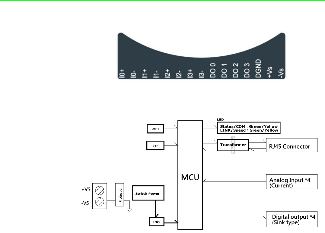
2.2.3 Pin Assignment ........................................................................... 14
Figure 2.3 WISE-4010/LAN Pin Assignment ............................. 14
2.2.4 Block Diagram............................................................................. 14
Figure 2.4 WISE-4010/LAN Block Diagram............................... 14
2.3 WISE-4050/LAN...................................................................................... 14
2.3.1 I/O Specification.......................................................................... 14
2.3.2 Application Wiring ....................................................................... 15
Figure 2.5 WISE-4050/LAN Digital Input Wiring Diagram ......... 15
Figure 2.6 WISE-4050/LAN Digital Output Wiring Diagram....... 15
2.3.3 Pin Assignment ........................................................................... 16
Figure 2.7 WISE-4050/LAN Pin Assignment ............................. 16
2.3.4 Block Diagram............................................................................. 16
Figure 2.8 WISE-4050/LAN Block Diagram............................... 16
2.4 WISE-4060/LAN...................................................................................... 17
2.4.1 I/O Specification.......................................................................... 17
2.4.2 Application Wiring ....................................................................... 18
Figure 2.9 WISE-4060/LAN Digital Input Wiring Diagram ......... 18
Figure 2.10WISE-4060/LAN Relay Output Wiring Diagram ....... 18
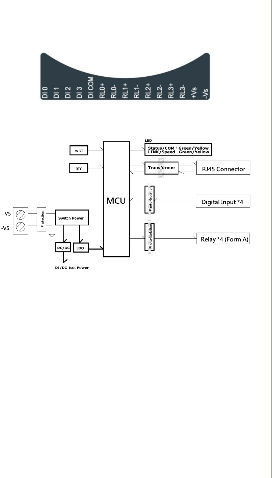
2.4.3 Pin Assignment ........................................................................... 19
Figure 2.11WISE-4060/LAN Pin Assignment ............................. 19
2.4.4 Block Diagram............................................................................. 19
Figure 2.12WISE-4060/LAN Block Diagram............................... 19
2.5 WISE-4012E ........................................................................................... 20
2.5.1 I/O Specification.......................................................................... 20
2.5.2 Application Wiring ....................................................................... 22
Figure 2.13WISE-4012E Voltage Input Wiring Diagram............. 22

WISE-4000 User Manual vi
Figure 2.14WISE-4012E Digital Input Wiring Diagram............... 22
Figure 2.15WISE-4012E Relay Output Wiring Diagram ............. 22
2.5.3 Pin Assignment........................................................................... 23
Figure 2.16WISE-4012E Pin Assignment................................... 23
2.5.4 Block Diagram ............................................................................ 23
Figure 2.17WISE-4012E Block Diagram .................................... 23
2.6 WISE-4050.............................................................................................. 24
2.6.1 I/O Specification.......................................................................... 24
2.6.2 Application Wiring ....................................................................... 25
Figure 2.18WISE-4050 Digital Input Wiring Diagram ................. 25
Figure 2.19WISE-4050 Digital Output Wiring Diagram .............. 25
2.6.3 Pin Assignment........................................................................... 25
Figure 2.20WISE-4050 Pin Assignment ..................................... 25
2.6.4 Block Diagram ............................................................................ 26
Figure 2.21WISE-4050 Block Diagram....................................... 26
2.7 WISE-4060.............................................................................................. 27
2.7.1 I/O Specification.......................................................................... 27
2.7.2 Application Wiring ....................................................................... 28
Figure 2.22WISE-4060 Digital Input Wiring Diagram ................. 28
Figure 2.23WISE-4060 Relay Output Wiring Diagram ............... 28
2.7.3 Pin Assignment........................................................................... 28
Figure 2.24WISE-4060 Pin Assignment ..................................... 28
2.7.4 Block Diagram ............................................................................ 29
Figure 2.25WISE-4060 Block Diagram....................................... 29
Chapter 3 Hardware Installation........................ 31
3.1 Interface Introduction .............................................................................. 32
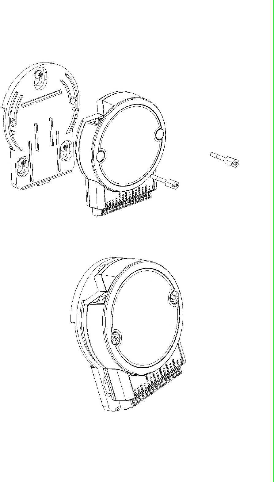
3.2 Mounting ................................................................................................. 32
3.2.1 DIN-Rail Mounting ...................................................................... 32
Figure 3.1 Mounting Kit Back View............................................ 32
Figure 3.2 Installing the Mounting Kit for a DIN-Rail ................. 32
Figure 3.3 Mounting on the DIN-Rail ......................................... 33
Figure 3.4 Rear View of DIN-Rail Mounting .............................. 33
3.2.2 Wall Mounting............................................................................. 34
Figure 3.5 Mounting Kit Dimensions.......................................... 34
Figure 3.6 Wall Mounting........................................................... 35
Figure 3.7 Wall Mounting Finished ............................................ 35
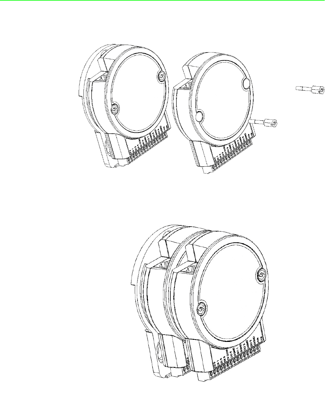
3.2.3 Stack Mounting ........................................................................... 36
Figure 3.8 Stack Mounting......................................................... 36
Figure 3.9 Finished Stack Mounting .......................................... 36
3.3 Wiring & Connections ............................................................................. 37
3.3.1 Power Supply Wiring (Not for WISE-4012E) .............................. 37
Figure 3.10Power Supply Wiring ................................................ 37
3.3.2 USB Power (WISE-4012E Only)................................................. 37
Figure 3.11USB Power Supply Wiring........................................ 38
3.3.3 I/O Units...................................................................................... 38
Chapter 4 System Configuration....................... 39
4.1 Connection.............................................................................................. 40
4.2 Configure WISE Using the Web Interface............................................... 40
4.2.1 System Requirements ................................................................ 40
4.2.2 List of WISE-4000 Default Ethernet Ports ................................ 41
4.2.3 Factory Default Settings ............................................................. 41

vii WISE-4000 User Manual
4.2.4 Module Authorization .................................................................. 41
4.2.5 Operation Mode .......................................................................... 41
4.2.6 Using a Browser to Configure the Module ................................. 42
4.2.7 Configuring Cloud Server (WISE-4000 wireless series only)...... 58
4.3 Configure WISE-4000 with ADAM.NET Utility ........................................ 61
4.3.1 Operation Framework ................................................................. 61
4.3.2 Configure WISE-4000 ................................................................. 66
4.4 Site Survey Tool for WISE-4000 Wireless Series ................................... 69
4.4.1 Site Survey Architecture ............................................................ 69
4.4.2 Site Survey Mode........................................................................ 69
4.4.3 Site Survey Tool.......................................................................... 70
Appendix A I/O Modbus Mapping Table...............71
A.1 Modbus Function Code Introduction ....................................................... 72
A.2 WISE-4010/LAN Modbus Mapping Table ............................................... 72
A.3 WISE-4050/LAN Modbus Mapping Table ............................................... 76
A.4 WISE-4060/LAN Modbus Mapping Table ............................................... 78
A.5 WISE-4012E Wireless Modbus Mapping Table ...................................... 80
A.6 WISE-4050 Wireless Modbus Mapping Table ........................................ 83
A.7 WISE-4060 Wireless Modbus Mapping Table ........................................ 85
Appendix B REST for WISE-4000 Series ..............87
B.1 Introduction ............................................................................................. 88
B.2 REST Resources for WISE-4000 Series................................................. 89
B.2.1 Digital Input ................................................................................. 89
B.2.2 Digital Output .............................................................................. 94
B.2.3 Analog Input................................................................................ 99
B.2.4 Data Logger .............................................................................. 105

WISE-4000 User Manual viii

Chapter 1
1Product Overview
WISE-4000 User Manual 2
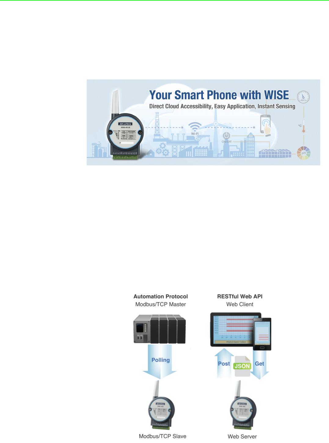
1.1 Introduction
WISE-4000 series is an Ethernet-based wired or wireless IoT device, which inte-
grated with IoT data acquisition, processing, and publishing functions. Except various
I/O type offering, WISE-4000 series provides data pre-scaling, data logic, and data
logger functions. These data can be access via mobile devices and be published to
cloud with security in anytime and anywhere.
1.2 Feature Highlights
1.2.1 RESTful Web Service
Representational State Transfer (REST) is a software architecture style widely used
for creating scalable web services. With the advantage of scalability, simplicity and
performance, it's already adopted in IoT applications. It is based on Hypertext Trans-
fer Protocol (HTTP) and uses verbs, like GET, POST, PUT, DELETE, etc., for web
browsers to get web pages or retrieve data with remote servers. The data can be
retrieved by internet media like HTML, XML, or JSON. REST s a uniform resource
identifier (URI) to identify the data. Like using “http://10.0.0.1/analoginput/ch0” to
identify the analog input value of channel 0. Then the web server may retrieve a
JSON file analog input value of channel 0.
3 WISE-4000 User Manual
Chapter 1 Product Overview
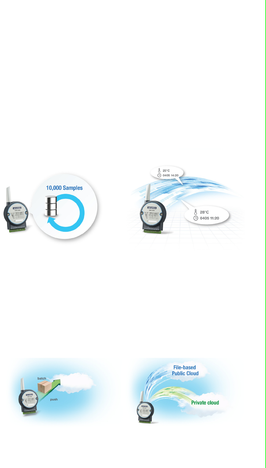
1.2.2 Data Storage Function
The internal flash of the WISE module can log up to 10,000 data samples with a time
stamp. The I/O data can be logged periodically, and when the I/O status changes.
Once the memory is full, users can choose to overwrite the old data to ring log or just
stop the log function. When the module is powered-off, data can be kept in the mod-
ule. When restarting, users can decide whether to clear all data or continue logging.
The definition of data in the IoT is not only the status of everything, but also includes
time or location information. With a built-in Real Time Clock (RTC), WISE modules
log data with a time stamp and the MAC address of the WISE module. The internal
RTC can be calibrated by SNTP with time server. Once the module has been pow-
ered-off, the internal time can also be saved using the time backup battery. When
users poll the data from the data logger, the time stamp will always be attached to the
data.
1.2.3 IoT Cloud Function
Local storage data not only can be polled by the user, it can also be pushed to the
cloud automatically. Once the logger reaches the upload criteria, Data Logger will
push the data to public cloud services like Dropbox or Baidu. This data will be saved
on the cloud using a *.csv file extension. Users can synchronize the data on the cloud
using the application program provided by the cloud provider where it can be
accessed from anywhere. With the provided RESTful API, users can configure their
private cloud and push the data onto it. Cloud Logger provides a very flexible solution
for cloud data storage. A WISE module is the only one stop from data acquisition to
the cloud.

WISE-4000 User Manual 4
1.3 Series Family and Specifications
1.3.1 Series Family
Interface Model Description
WLAN
WISE-4012E 6-ch Input/Output
IoT Wireless I/O Module for IoT Developers
WISE-4050 4-ch Digital Input and 4-ch Digital Output
IoT Wireless I/O Module
WISE-4060 4-ch Digital Input and 4-ch Relay Output
IoT Wireless I/O Module
LAN
WISE-4010/LAN 4-ch Current Input and 4-ch Digital Output
IoT Ethernet I/O Module
WISE-4050/LAN 4-ch Digital Input and 4-ch Digital Output
IoT Ethernet I/O Module
WISE-4060/LAN 4-ch Digital Input and 4-ch Relay Output
IoT Ethernet I/O Module
5 WISE-4000 User Manual
Chapter 1 Product Overview
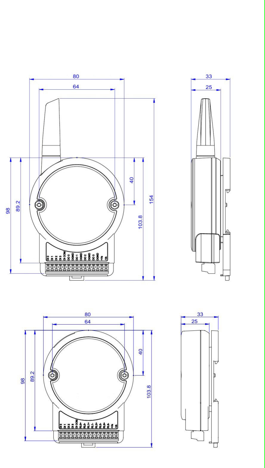
1.4 Mechanical Design and Dimensions
1.4.1 WISE-4000 Wireless Series Dimensions
1.4.2 WISE-4000/LAN Dimensions

WISE-4000 User Manual 6
1.5 Switch
Note 1 After the position 1 of SW1 been changed, user need to power on the
module again to apply the operation mode
Note 2 SW2 in only for WISE-4050(/LAN) and WISE-4060(/LAN), all 4 channels
have to be configured to dry contact or wet contact in the same time, and
both P1 and P2 have to be changed together
1.6 LED Definition
WISE-4000 Wireless Series
WISE-4000/LAN Series
Switch Description Position ON (Default) OFF
SW1 Operation Mode P1 Normal Mode Initial Mode
P2 N/A N/A
SW2 DI Type
(all channels)
P1 Dry Contact Wet Contact
P2 Dry Contact Wet Contact
LED Color Indication Behavior
Status Green Blink 2Hz: Wait for connection
0.5Hz: Network Connected
ON 30 Sec When enable LOCATE function.
Com Yellow Blink When TX/RX data in transmission
AP/Infra Green ON Limited AP Mode
OFF Station Mode
Signal
Strength Green
ON *4 Full Signal
ON *3 Good Signal
ON *2 Okay Signal
ON *1 Poor Signal
All OFF No Signal/ Limited AP Mode
LED Color Indication Behavior
Status Green Blink Module is normally at work. (1Hz)
ON 30 Sec When enable LOCATE function.
Com Yellow Blink When TX/RX data in transmission
Link Green ON Both ends of devices are connected
Speed Yellow ON/OFF ON: 100 Mbps
OFF: Less than 10 Mbps

7 WISE-4000 User Manual
Chapter 1 Product Overview
1.7 Certification and Safety Standard
WISE-4000/LAN Series
FCC
–FCC Part 15 Class A
–IC ICES-003
CE
–EN 55011 (Group 1, CLASS A)
–EN 55022
–EN 61000-6-4
–EN 61000-6-2
–IEC 61000-4-2
–IEC 61000-4-3
–IEC 61000-4-4
–IEC 61000-4-5
–IEC 61000-4-6
–IEC 61000-4-8
–IEC 61000-4-11
–RoHS
China RoHS
WISE-4000 Wireless Series
FCC
–FCC Part 15 Class A
–IC ICES-003
CE
–EN 55011 (Group 1, CLASS A)
–EN 55022
–EN 61000-6-4
–EN 61000-6-2
–IEC 61000-4-2
–IEC 61000-4-3
–IEC 61000-4-4
–IEC 61000-4-5
–IEC 61000-4-6
–IEC 61000-4-8
–IEC 61000-4-11
–RoHS
NCC
SRRC
China RoHS

WISE-4000 User Manual 8
1.8 Package Information
WISE-4000 Wireless Series
WISE-4000 Module with bundle antenna and terminal connector x1
Mounting bracket x1
Quick startup manual with China RoHS declare
WISE-4000/LAN Series
WISE-4000/LAN Module
Mounting bracket x1
Quick startup manual with China RoHS declare
WISE-4012E
WISE-4012E Module with bundle antenna and terminal connector x1
Quick startup manual with China RoHS declare
USB drive with WebAccess (WISE-4012E-IDK only)
USB power cable
Extension board
Screwdriver

Chapter 2
2Product Specifications

WISE-4000 User Manual 10
2.1 General Specification
WLAN Interface
Standard Conformance:
–802.11b
–802.11g
–802.11n (2.4GHz only)
Network Modes:
–Limited AP (Wireless Server)
–Station/Infrastructure (Wireless Client)
LAN Interface
Ethernet: IEEE 802.3u 10/100Base-T(X)
Connector: 1-port RJ-45
General
I/O Connector: 3.5mm spacing, 15-pole, plug-in screw terminal block
Power Connector: Micro-B USB for WISE-4012E, other modules use same con-
nector as I/O
Watchdog Timer
–System: 1.6 second
–Communication
–Programmable (FSV)
RTC Accuracy: 3 min/month (WISE-4012E does not provide RTC)
Enclosure: PC
Mounting: DIN 35 rail, wall, and stack
Dimensions (W x H x D)
–With bundle antenna
–Without bundled antenna: 80 x 89 x 25 mm
Operation Temperature:
–WISE-4000 Wireless Series: -25~70°C (-13~158°F)
–WISE-4000/LAN Series: -40~70°C (-40~158°F)
Cold Start Temperature
–WISE-4000 Wireless Series: -20~70°C (-4~158°F)
–WISE-4000/LAN Series: -40~70°C (-40~158°F)
Storage Temperature: -40~85°C (-40~185°F)
Operating Humidity: 20~ 95% RH (non-condensing)
Storage Humidity: 0~95% RH (non-condensing)
Note! Equipment will operate below 30% humidity. However, static electricity
problems occur much more frequently at lower humidity levels. Make
sure you take adequate precautions when you touch the equipment.
Consider using ground straps, anti-static floor coverings, etc. if you use
the equipment in low humidity environments.

11 WISE-4000 User Manual
Chapter 2 Product Specifications
Power
Power Input Voltage: 10~30 VDC (24 VDC Standard)
–WISE-4050
–WISE-4060
–WISE-4010/LAN
–WISE-4050/LAN
–WISE-4060/LAN
USB 5VDC
–WISE-4012E
Power Consumption
–WISE-4012E: 2.2 W @ 5 VDC
–WISE-4050: 2.2 W @ 24 VDC
–WISE-4060: 2.5 W @ 24 VDC
–WISE-4010/LAN: 1.2 W @ 24 VDC
–WISE-4050/LAN: 2.2 W @ 24 VDC
–WISE-4060/LAN: 2.5 W @ 24 VDC
Reverse Power Protection (not for WISE-4012E)
Software
Configuration Interface: Web Interface, Windows Utility
Utility: WISE-4000/Apax .NET Utility
Driver: WISE-4000 .NET Class Library
Industrial Protocol: Modbus/TCP
Supported Protocols: TCP/IP, UDP, HTTP, HTTPS, DHCP, ARP, SNTP
Supports RESTful Web API in JSON format
Supports Web Server in HTML5 with JavaScript & CSS3
Note! RTC Accuracy: 3 min/month (WISE-4012E does not provide RTC)

WISE-4000 User Manual 12
2.2 WISE-4010/LAN
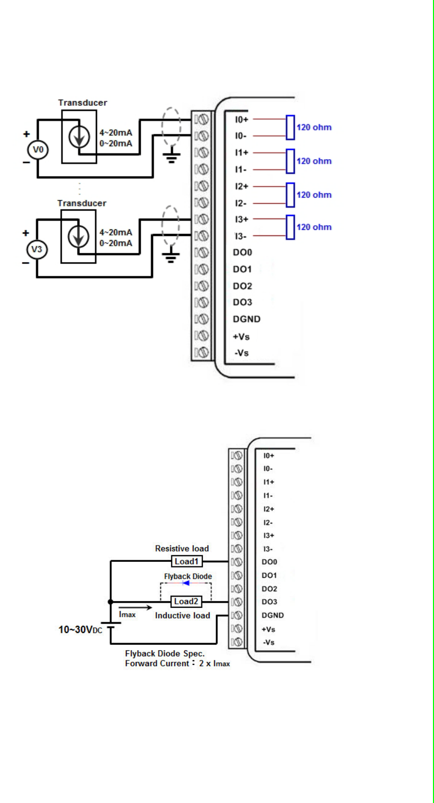
2.2.1 I/O Specification
Current Input
–Channel: 4
–Resolution: 12-bit
–Sampling Rate: 10/100 Hz/channel
–Accuracy: ±0.2% of FSR @ 25°C
–Input Range: 0~20 mA, 4~20 mA (Select by Web Configuration)
–Input Impedance: 120 Ω
–Burn-out Detection: Yes (4~20 mA only)
–Supports Data Scaling and Averaging
Digital Output
–Channels: 4
–Open collector to 30 V, 500 mA max. for resistance load
–Inductive loads require an external diode to eliminate back-EMF when the
DO is turned off
–On Resistance (RDS(ON)): 0.7 Ω (max.) @ 500mA, 25°C
–Supports 1 kHz Pulse Output
–Supports High-to-Low and Low-to-High Delay Output
13 WISE-4000 User Manual
Chapter 2 Product Specifications
2.2.2 Application Wiring
Figure 2.1 WISE-4010/LAN Current Input Wiring Diagram
Figure 2.2 WISE-4010/LAN Digital Output Wiring Diagram
WISE-4000 User Manual 14
2.2.3 Pin Assignment
Figure 2.3 WISE-4010/LAN Pin Assignment
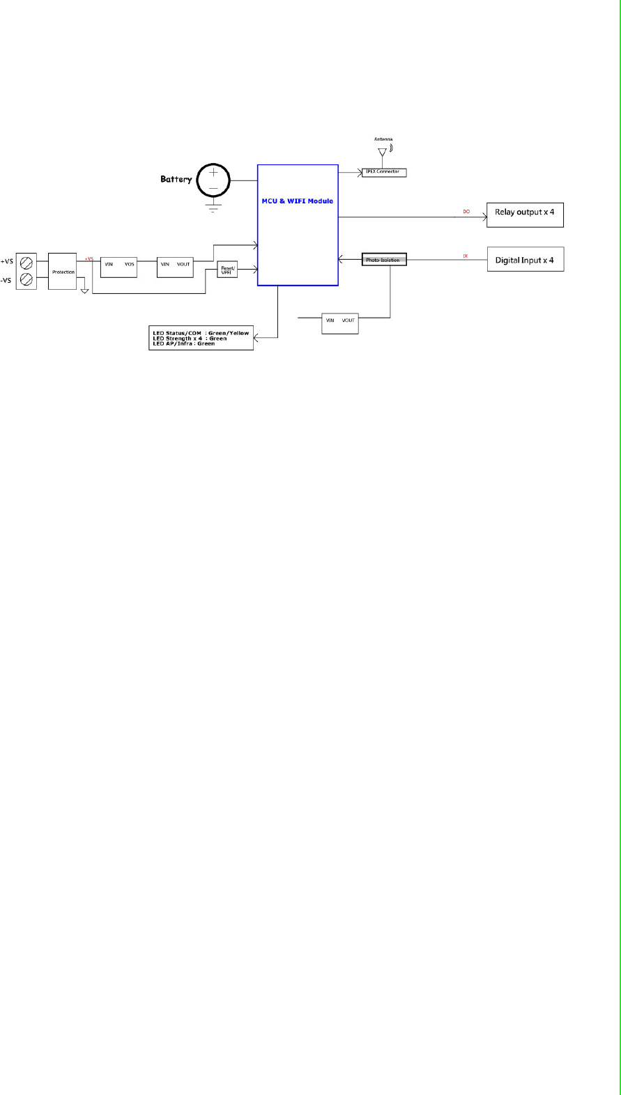
2.2.4 Block Diagram
Figure 2.4 WISE-4010/LAN Block Diagram
2.3 WISE-4050/LAN
2.3.1 I/O Specification
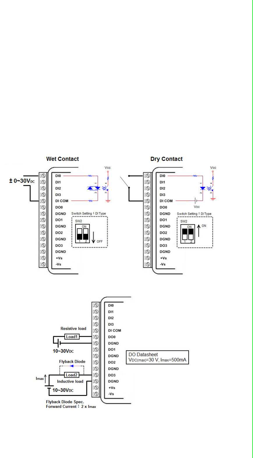
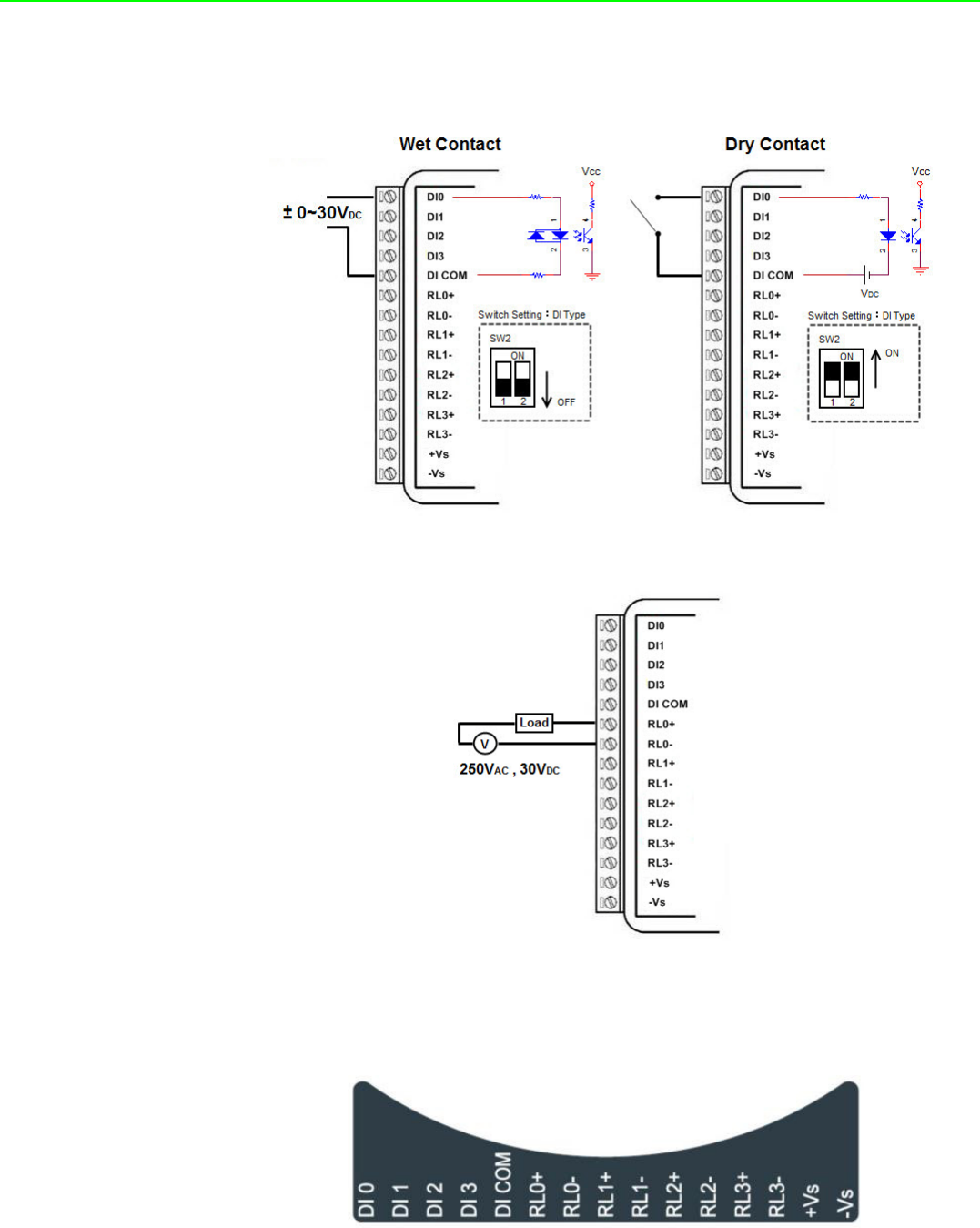
Digital Input
–Channel: 4
–Logic level
–Dry Contact 0: Open
1: Close to DI COM
–Wet Contact 0: 0~3 VDC or -3~0 VDC
1: 10~30 VDC or -30~-10 VDC (3 mA min.)
–All 4 channels should be configured to dry contact or wet contact in the
same time
–Isolation: 3,000 Vrms
–Supports 32-bit Counter Input Function (Maximum signal frequency 3 kHz)
–Keep/Discard Counter Value when Power-off
–Supports Frequency Input Function (Maximum frequency 3 kHz)
–Supports Inverted DI Status
15 WISE-4000 User Manual
Chapter 2 Product Specifications
Digital Output
–Channels: 4
–Open collector to 30 V, 500 mA max. for resistance load
– Inductive loads require an external diode to eliminate back-EMF when the
DO is turned off
–Isolation: 3,000 Vrms
–On Resistance (RDS(ON)): 0.7 Ω (max.) @ 500mA, 25°C
–Supports 1 kHz Pulse Output
–Supports High-to-Low and Low-to-High Delay Output
2.3.2 Application Wiring
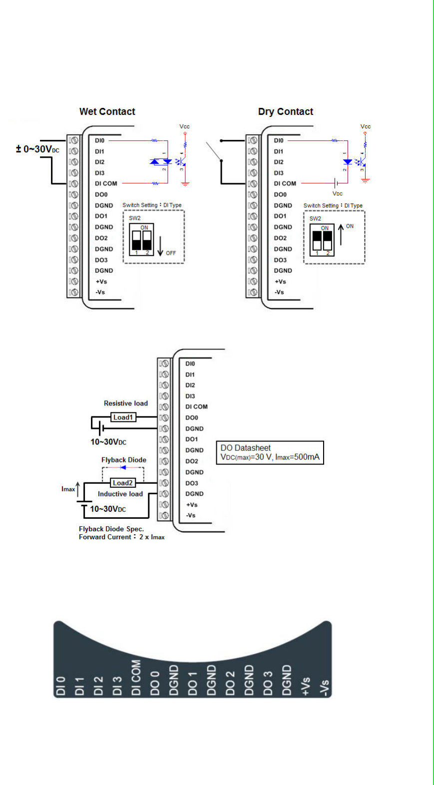
Figure 2.5 WISE-4050/LAN Digital Input Wiring Diagram
Figure 2.6 WISE-4050/LAN Digital Output Wiring Diagram

WISE-4000 User Manual 16
2.3.3 Pin Assignment
Figure 2.7 WISE-4050/LAN Pin Assignment
2.3.4 Block Diagram
Figure 2.8 WISE-4050/LAN Block Diagram

17 WISE-4000 User Manual
Chapter 2 Product Specifications
2.4 WISE-4060/LAN
2.4.1 I/O Specification
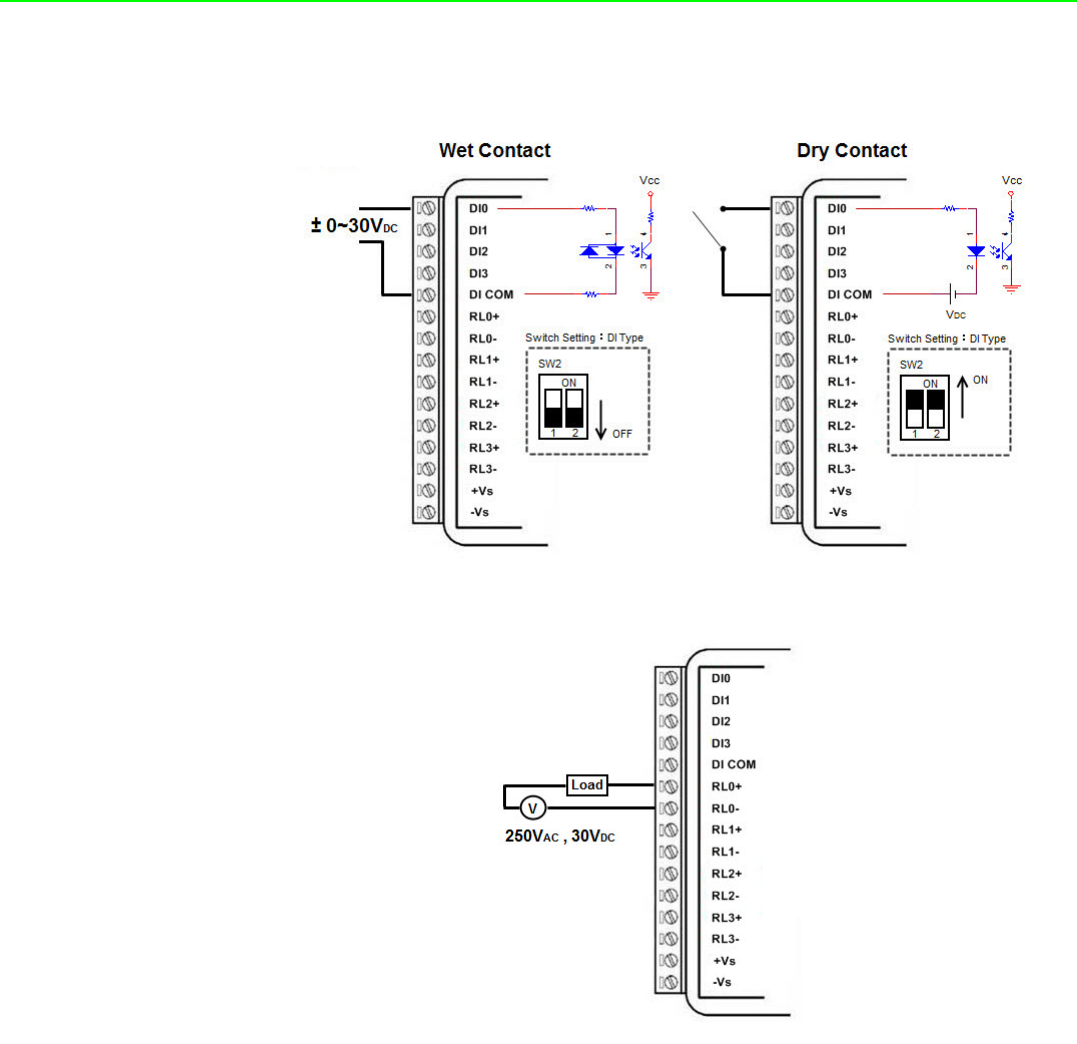
Digital Input
–Channel: 4
–Logic level
–Dry Contact 0: Open
1: Close to DI COM
–Wet Contact 0: 0~3 VDC or -3~0 VDC
1: 10~30 VDC or -30~-10 VDC (3 mA min.)
–Isolation: 3,000 Vrms
–Supports 32-bit Counter Input Function (Maximum signal frequency 3 kHz)
–Keep/Discard Counter Value when Power-off
–Supports Frequency Input Function (Maximum frequency 3 kHz)
–Supports Inverted DI Status
Relay Output
–Channels: 4 (Form A)
–Contact Rating (Resistive Load)
–250 VAC @ 5 A
–30 VDC @ 3 A
–Relay On Time: 10 ms
–Relay Off Time: 5 ms
–Insulation Resistance: 1 GΩ min. @ 500 VDC
–Dielectric Strength
–Between Contacts: 1000 VAC (1min)
–Between Coil to Contact: 3000 VAC (1min)
–Maximum Switching: 60 operations/minute
–Supports Pulse Output
–Supports High-to-Low and Low-to-High Delay Output
WISE-4000 User Manual 18
2.4.2 Application Wiring
Figure 2.9 WISE-4060/LAN Digital Input Wiring Diagram
Figure 2.10 WISE-4060/LAN Relay Output Wiring Diagram
19 WISE-4000 User Manual
Chapter 2 Product Specifications
2.4.3 Pin Assignment
Figure 2.11 WISE-4060/LAN Pin Assignment
2.4.4 Block Diagram
Figure 2.12 WISE-4060/LAN Block Diagram

WISE-4000 User Manual 20
2.5 WISE-4012E
2.5.1 I/O Specification
Voltage Input
–Channel: 2
–Resolution: 12-bit
–Sampling Rate: 10 Hz (Total)
–Accuracy: ±0.1 VDC
–Input Range: 0~10 VDC
–Input Impedance: 100 kΩ
–Supports Data Scaling and Averaging
Digital Input
–Channel: 2
–Logic level
–Dry Contact 0: Open
1: Close to GND
–Supports 32-bit Counter Input Function (Maximum signal frequency 3 kHz)
–Keep/Discard Counter Value when Power-off
–Supports Frequency Input Function (Maximum frequency 3 kHz)
–Supports Inverted DI Status
Relay Output
–Channels: 2 (Form A)
–Contact Rating
–120 VAC @ 0.5 A
–30 VDC @ 1A
–Relay On Time: 5 ms
–Relay Off Time: 6 ms
–Insulation Resistance: 1 GΩ min. @ 500 VDC
–Dielectric Strength
–Between Contacts: 1000 VAC (1min)
–Between Coil to Contact: 1500 VAC (1min)
–Maximum Switching: 60 operations/minute
–Supports Pulse Output
–Supports High-to-Low and Low-to-High Delay Output
Note! The analog input channels of the WISE-4012E do not support 50/60 Hz
noise rejection. The following methods can help to reduce noise:
Power up WISE-4012E by power bank
Supply sensor power by battery
Wiring V0- and V1- pin to GND pin

21 WISE-4000 User Manual
Chapter 2 Product Specifications
Note! The analog input channel of the WISE-4012E does not support inverted
voltage protection, note that the input voltage should within 0~10VDC
WISE-4000 User Manual 22
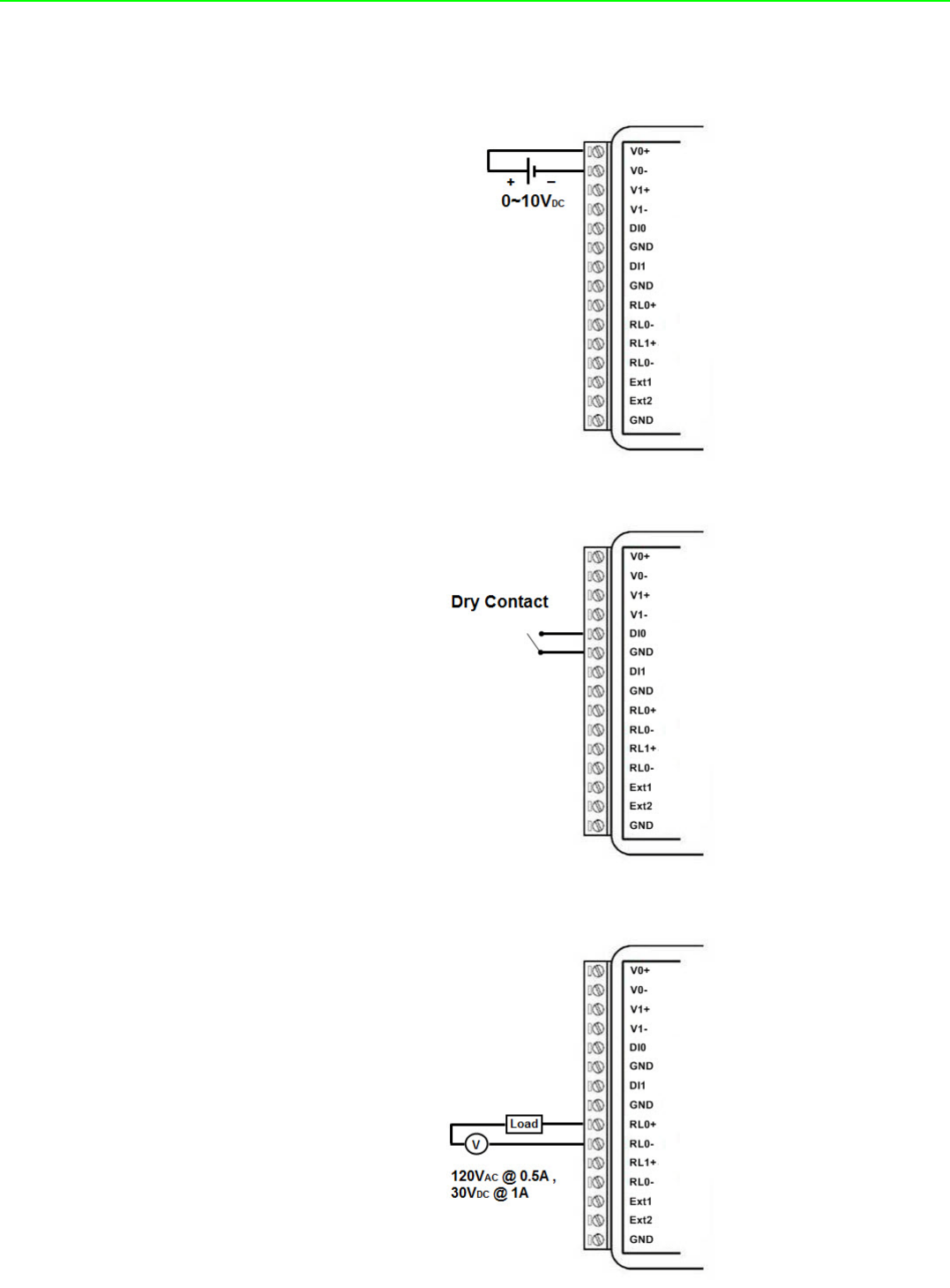
2.5.2 Application Wiring
Figure 2.13 WISE-4012E Voltage Input Wiring Diagram
Figure 2.14 WISE-4012E Digital Input Wiring Diagram
Figure 2.15 WISE-4012E Relay Output Wiring Diagram
23 WISE-4000 User Manual
Chapter 2 Product Specifications
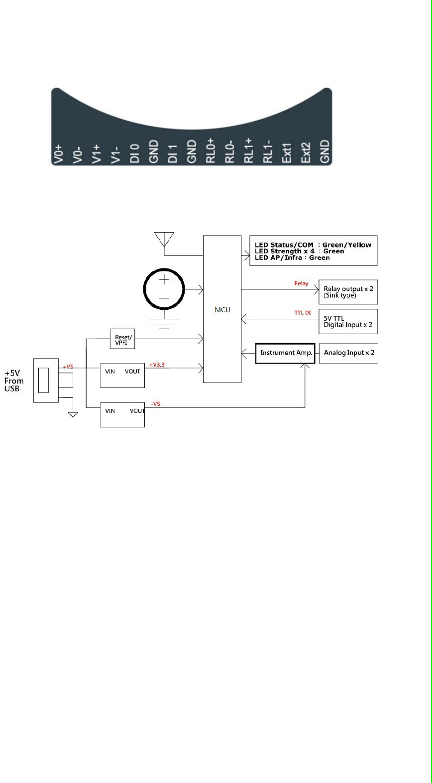
2.5.3 Pin Assignment
Figure 2.16 WISE-4012E Pin Assignment
2.5.4 Block Diagram
Figure 2.17 WISE-4012E Block Diagram

WISE-4000 User Manual 24
2.6 WISE-4050
2.6.1 I/O Specification
Digital Input
–Channel: 4
–Logic level
–Dry Contact 0: Open
1: Close to DI COM
–Wet Contact 0: 0~3 VDC
1: 10~30 VDC (3 mA min.)
–All 4 channels should be configured to dry contact or wet contact in the
same time
–Isolation: 3,000 Vrms
–Supports 32-bit Counter Input Function (Maximum signal frequency 3 kHz)
–Keep/Discard Counter Value when Power-off
–Supports Frequency Input Function (Maximum frequency 3 kHz)
–Supports Inverted DI Status
Digital Output
–Channels: 4
–Open collector to 30 V, 500 mA max. for resistance load
–Inductive loads require an external diode to eliminate back-EMF when the
DO is turned off
–Isolation: 3,000 Vrms
–On Resistance (RDS(ON)): 0.7 Ω (max.) @ 500mA, 25°C
–Supports 5 kHz Pulse Output
–Supports High-to-Low and Low-to-High Delay Output
25 WISE-4000 User Manual
Chapter 2 Product Specifications
2.6.2 Application Wiring
Figure 2.18 WISE-4050 Digital Input Wiring Diagram
Figure 2.19 WISE-4050 Digital Output Wiring Diagram
2.6.3 Pin Assignment
Figure 2.20 WISE-4050 Pin Assignment
WISE-4000 User Manual 26
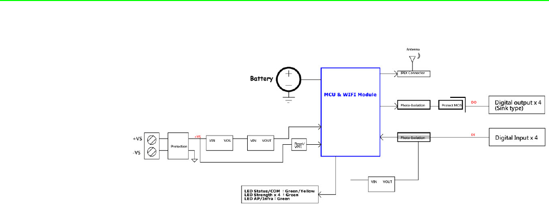
2.6.4 Block Diagram
Figure 2.21 WISE-4050 Block Diagram

27 WISE-4000 User Manual
Chapter 2 Product Specifications
2.7 WISE-4060
2.7.1 I/O Specification
Digital Input
–Channel: 4
–Logic level
–Dry Contact 0: Open
1: Close to DI COM
–Wet Contact 0: 0~3 VDC (0.8 mA max.)
1: 10~30 VDC (3 mA min.)
–Isolation: 3,000 Vrms
–Supports 32-bit Counter Input Function (Maximum signal frequency 3 kHz)
–Keep/Discard Counter Value when Power-off
–Supports Frequency Input Function (Maximum frequency 3 kHz)
–Supports Inverted DI Status
Relay Output
–Channels: 4 (Form A)
–Contact Rating (Resistive Load)
–250 VAC @ 5 A
–30 VDC @ 3 A
–Relay On Time: 10 ms
–Relay Off Time: 5 ms
–Insulation Resistance: 1 GΩ min. @ 500 VDC
–Dielectric Strength
–Between Contacts: 1000 VAC (1min)
–Between Coil to Contact: 3000 VAC (1min)
–Maximum Switching: 60 operations/minute
–Supports Pulse Output
–Supports High-to-Low and Low-to-High Delay Output
WISE-4000 User Manual 28
2.7.2 Application Wiring
Figure 2.22 WISE-4060 Digital Input Wiring Diagram
Figure 2.23 WISE-4060 Relay Output Wiring Diagram
2.7.3 Pin Assignment
Figure 2.24 WISE-4060 Pin Assignment
29 WISE-4000 User Manual
Chapter 2 Product Specifications
2.7.4 Block Diagram
Figure 2.25 WISE-4060 Block Diagram

WISE-4000 User Manual 30

Chapter 3
3Hardware Installation
WISE-4000 User Manual 32
3.1 Interface Introduction
3.2 Mounting
WISE-4000 modules are designed as compact units and are allowed to be installed
in the field site under the following methods.
3.2.1 DIN-Rail Mounting
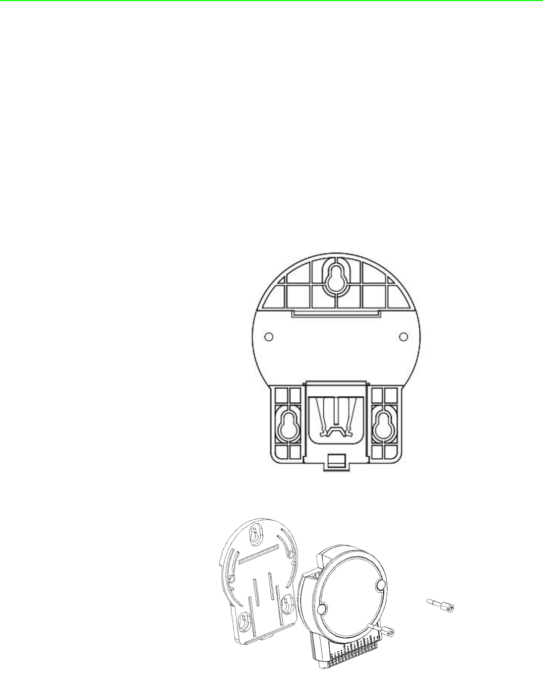
The WISE-4000 module can also be fixed to the cabinet by using mounting rails. You
need to assemble the DIN rail adapter to WISE-4000 module with flathead screw
driver as below. When the module is mounted on a rail, you may also consider using
end brackets at each end of the rail to keep the module from sliding horizontally along
the rail.
Figure 3.1 Mounting Kit Back View
Figure 3.2 Installing the Mounting Kit for a DIN-Rail

33 WISE-4000 User Manual
Chapter 3 Hardware Installation
Figure 3.3 Mounting on the DIN-Rail
Figure 3.4 Rear View of DIN-Rail Mounting
WISE-4000 User Manual 34
3.2.2 Wall Mounting
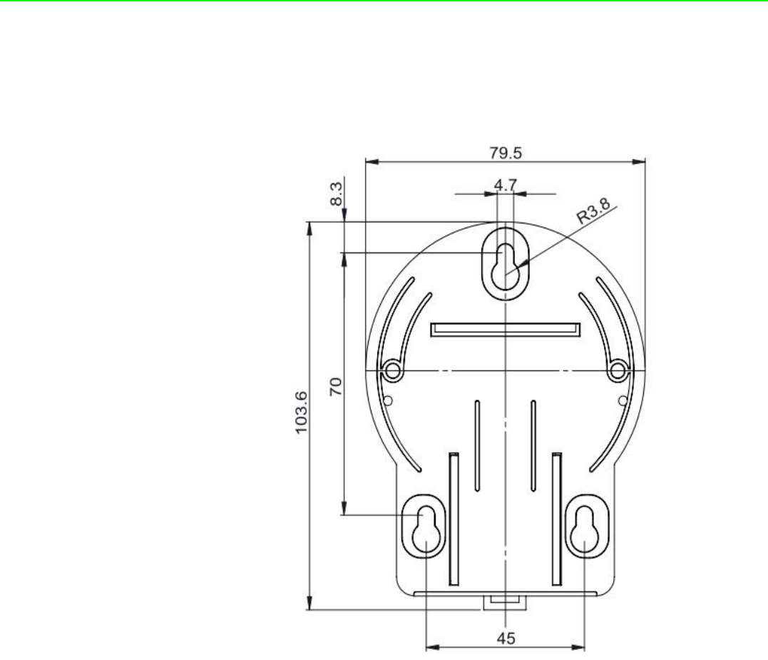
Each WISE-4000 module is packed with a plastic wall mounting bracket. User can
refer the bracket dimension and assembling figure to configure an optimal placement
in a wall, panel, or cabinet.
Figure 3.5 Mounting Kit Dimensions
35 WISE-4000 User Manual
Chapter 3 Hardware Installation
Figure 3.6 Wall Mounting
Figure 3.7 Wall Mounting Finished
WISE-4000 User Manual 36
3.2.3 Stack Mounting
Figure 3.8 Stack Mounting
Figure 3.9 Finished Stack Mounting
37 WISE-4000 User Manual
Chapter 3 Hardware Installation
3.3 Wiring & Connections
This section introduces basic information on wiring the power supply, I/O units, and
Ethernet connection.
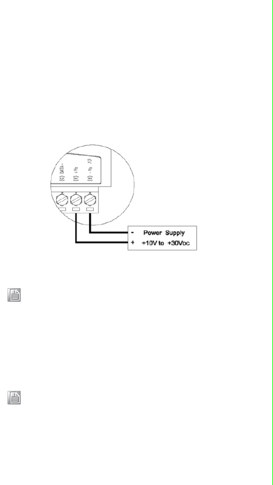
3.3.1 Power Supply Wiring (Not for WISE-4012E)
The system of WISE-4000 is designed for a standard industrial unregulated 24 VDC
power supply. For further application, it can also accept +10 to +30 VDC of power
input, 200mV peak to peak of power ripple, and the immediate ripple voltage should
be maintained between +10 and +30 VDC.
Screw terminals +Vs and -Vs are for power supply wiring
Figure 3.10 Power Supply Wiring
3.3.2 USB Power (WISE-4012E Only)
The system of WISE-4012E IoT Developer Kit is designed for a standard Micro-B
USB 5VDC power supply. Use the provided USB power cable to power up the mod-
ule. Insert the Micro-B USB end to the USB port on the side of the module, and insert
another end to Type-A 5VDC USB port such as a PC, notebook, USB power adapter,
USB power bank.
Note! The wires used should be at least 2 mm.
Note! The wider or flared part of the USB Micro-B connector is at the front side
of the module, please make sure the direction of the cable before insert-
ing it into the module to prevent the damage to the USB port.
Some USB power banks will automatically switch off, in this case, use a
standard USB power instead.

WISE-4000 User Manual 38
Figure 3.11 USB Power Supply Wiring
3.3.3 I/O Units
The system uses a plug-in screw terminal block for the interface between I/O mod-
ules and field devices. The following information must be considered when connect-
ing electrical devices to I/O modules.
1. The terminal block accepts wires from 0.5 mm to 2.5 mm.
2. Always use a continuous length of wire. Do not combine wires.
3. Use the shortest possible wire length.
4. Use wire trays for routing where possible.
5. Avoid running wires near high-energy wiring.
6. Avoid running input wiring in close proximity to output wiring.
7. Avoid creating sharp bends in the wires.

Chapter 4
4System Configuration
WISE-4000 User Manual 40
4.1 Connection
1. Plug a DC power source into the +Vs, -Vs pin of WISE module to turn the power
on, or plug in the USB power cable for the WISE-4012E.
2. For WISE-4000/LAN Series, connect your computer to Ethernet port of WISE
module with RJ-45 cross-over Ethernet cable, and configure the IP address of
your computer as same IP domain as default IP address of module: 10.0.0.1. Or
the wireless router can be used for configure the WISE-4000/LAN Series by
mobile devices or computer with wireless adapter.
3. For WISE-4000 Wireless Series, the default operation mode in normal mode is
AP Mode, or you can change position 1 of SW1 to OFF as in Section 1.5, to set-
ting the module as Initial Mode, then module must be AP Mode. Now the mod-
ule can be searched by mobile devices or wireless adapter of computer with
SSID: WISE-4xxx_MACAddress. Click the SSID to connect the module in AP
Mode, WISE module will auto assign the IP address for mobile devices or com-
puter.
4.2 Configure WISE Using the Web Interface
4.2.1 System Requirements
WISE-4000 module is developed by public HTML 5 base, but for detailed indication
and data transmission mode may be different on Web page of the operating system.
For mobile devices, the minimum requirement of web browsers as below:
Safari 6 in Apple iOS
Web Browser in Google Android 4.0 (Ice Cream Sandwich)
Chrome in Google Android 4.0 (Ice Cream Sandwich)
For PC platforms, the minimum requirement of web browsers as below:
Internet Explorer (version 11)
Google Chrome (version 30)
Mozilla Firefox (version 25)
Mobile Browse Chrome Android Safari
Configuration Y Y Y
File Upload N N N
Data Log Chart Y Y Y
Data Log Export N N N
Mobile Browse Chrome Firefox Safari IE11 IE10 IE9
Configuration Y Y Y Y Y Y
File Upload Y Y N Y N N
Data Log Chart Y Y Y Y Y N
Data Log Export Y Y N N N N

41 WISE-4000 User Manual
Chapter 4 System Configuration
4.2.2 List of WISE-4000 Default Ethernet Ports
4.2.3 Factory Default Settings
WISE-4000/LAN Series
Operation Mode: Normal Mode
IP Mode: Static IP Address
Default IP: 10.0.0.1
Subnet Mask: 255.0.0.0
Default Gateway: 0.0.0.0
Default Connection Timeout: 720 second
HTTP Port: 80
WISE-4000 Wireless Series
Operation Mode: Normal Mode
Wireless Mode: AP Mode
IP Mode: Static IP Address
Default IP: 192.168.1.1
Subnet Mask: 255.255.255.0
Default Gateway: 192.168.1.1
DHCP Server: Enabled
Default Connection Timeout: 720 second
HTTP Port: 80
4.2.4 Module Authorization
4.2.5 Operation Mode
The operation mode can be configured by switch SW1 on the back of module. Please
refer to previous chapter for the detail of configuring SW1.
Application Protocol Port Note
WebServer TCP 80 Configurable
Modbus Server TCP 502 -
Search Engine UDP 5048 -
SNTP Client UDP - Randomly
Account Default Password Access Ability
root 00000000 All the privileges
admin 00000000 All the privileges except access control configuration
user 00000000 View module status only, not allow to do configuration
Mode WISE-4000/LAN Series WISE-4000 Wireless Series
Initial Mode Fixed IP address: 10.0.0.1 Fixed IP address: 192.168.1.1
Fixed Wi-Fi Mode: AP Mode
Normal Mode Default IP address: 10.0.0.1 Default IP address: 192.168.1.1
Default Wi-Fi Mode: AP Mode
WISE-4000 User Manual 42
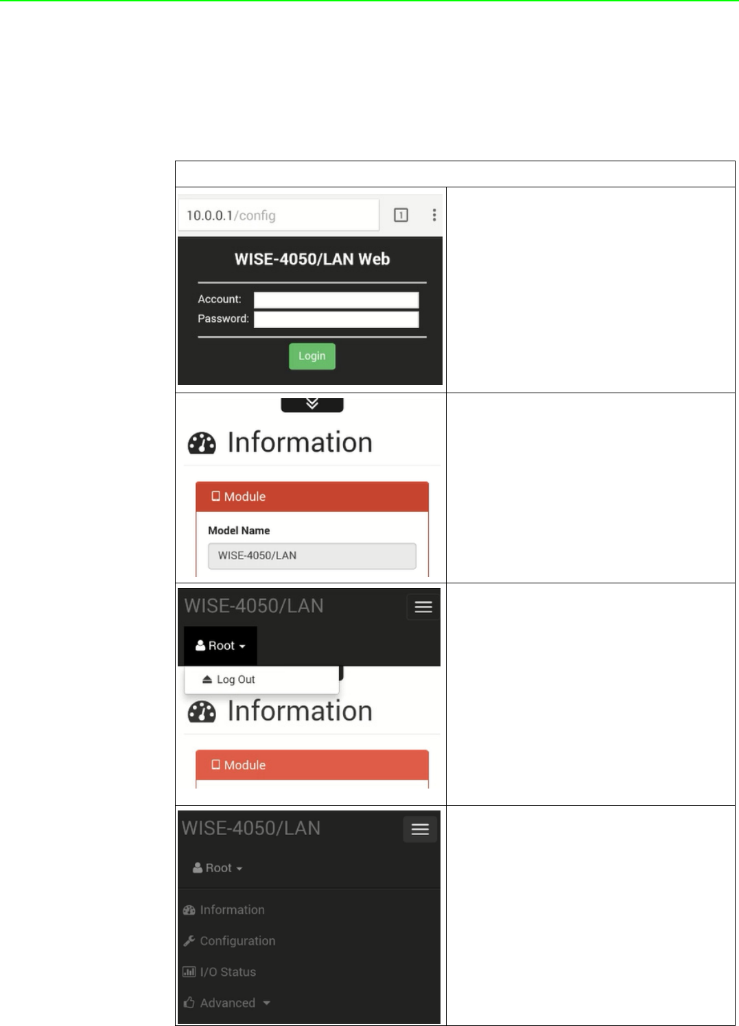
4.2.6 Using a Browser to Configure the Module
Configure URL: http://IP_address/config
Default URL:
WISE-4000/LAN Series: http://10.0.0.1/config
WISE-4000 Wireless Series: http://192.168.1.1/config
Configuration Steps
Login Web Configuration Page
1. Wirelessly connect your smart phone
to your local Ethernet network and
open the browser of your smart
phone.
2. Enter IP address of module with "/
config", for example, the default URL:
http://10.0.0.1/config or http://
192.168.1.1/config
3. Then you will see the login page,
please enter the account and pass-
word, then click Login button
4. After login you will see the configura-
tion web page
5. Scroll down the tab, you can change
the login user here
6. Click the button on the top, you can
switch to other pages