Aerohive Networks AP1130 Access Point User Manual AP1130 Installation Guide

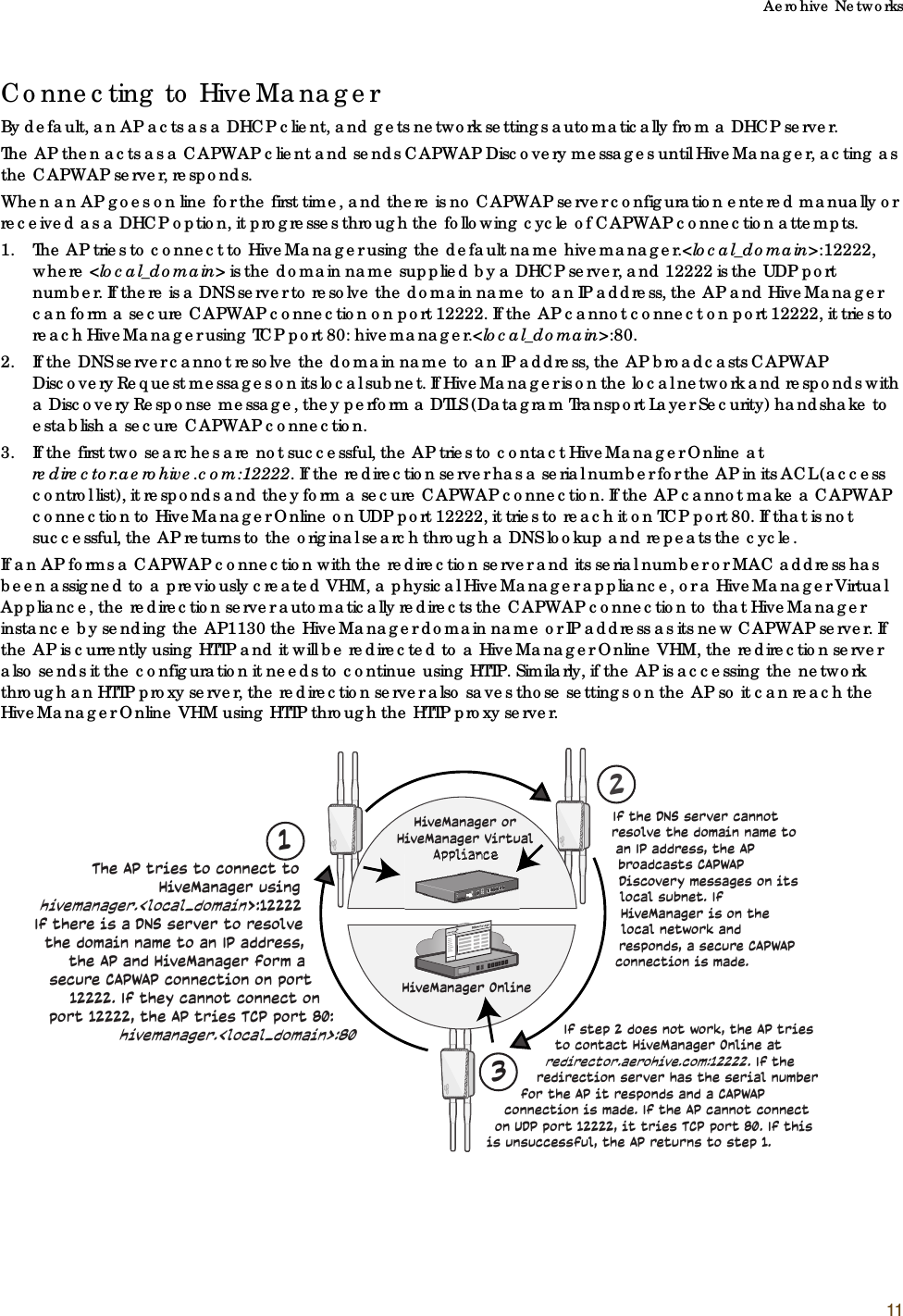
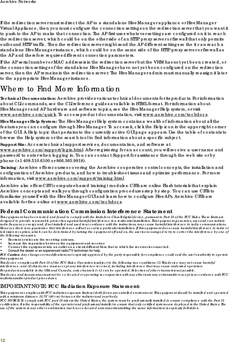
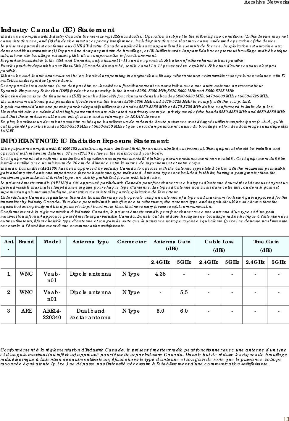
Aerohive Networks, Inc. Access Point AP1130 Installation Guide

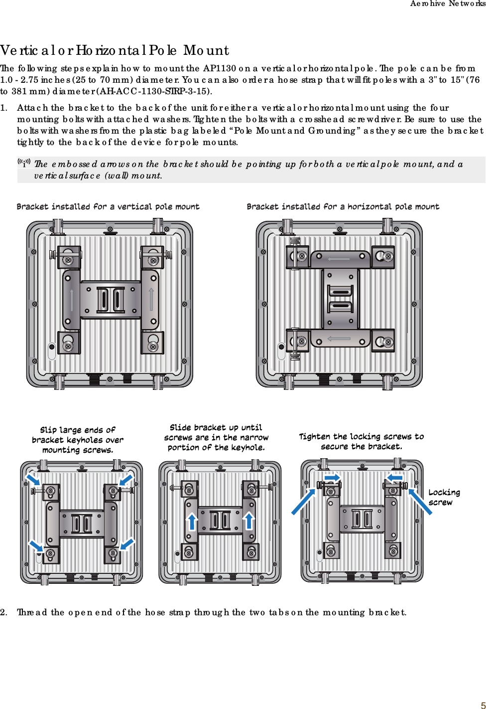
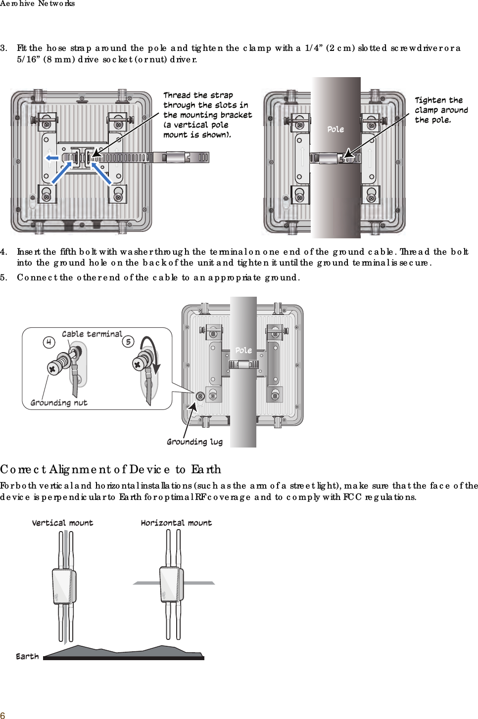
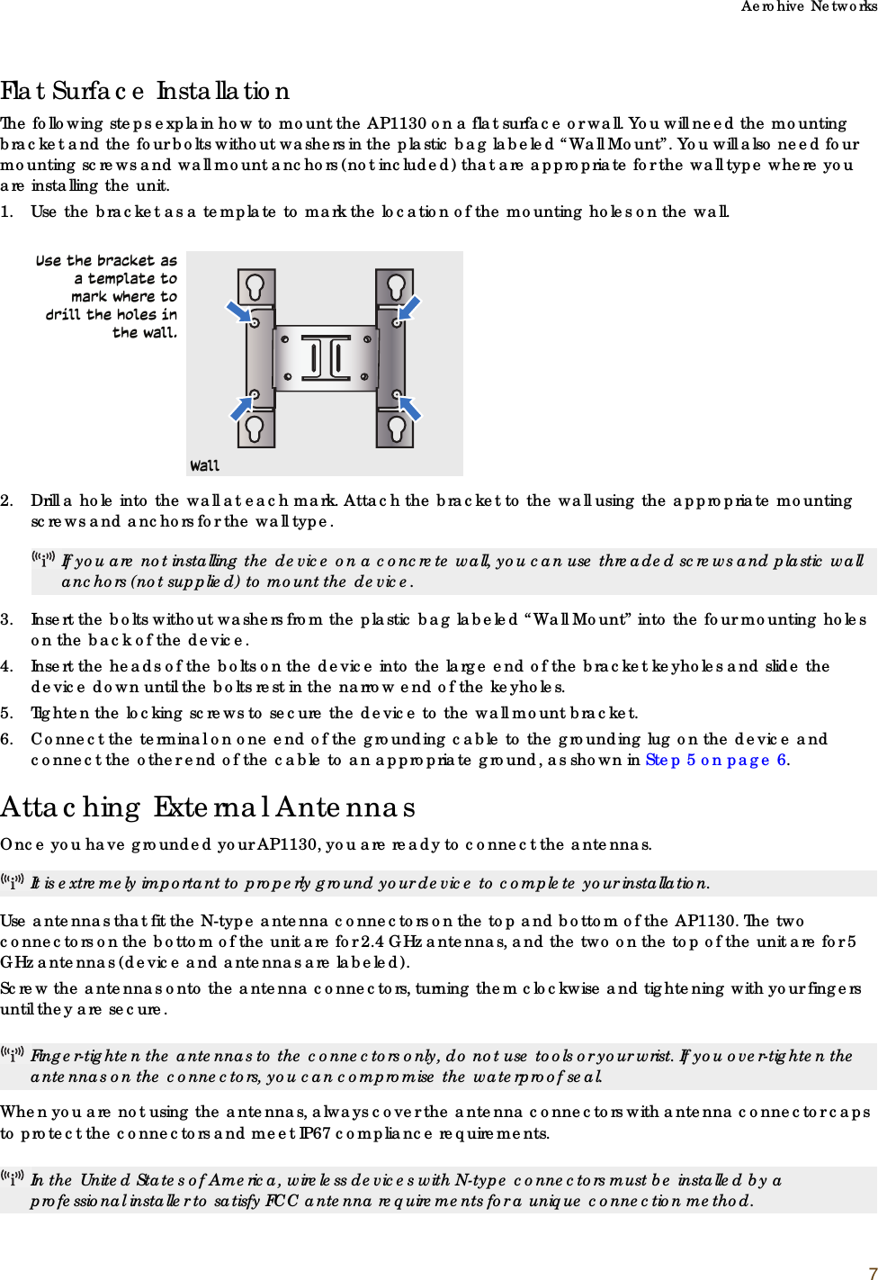
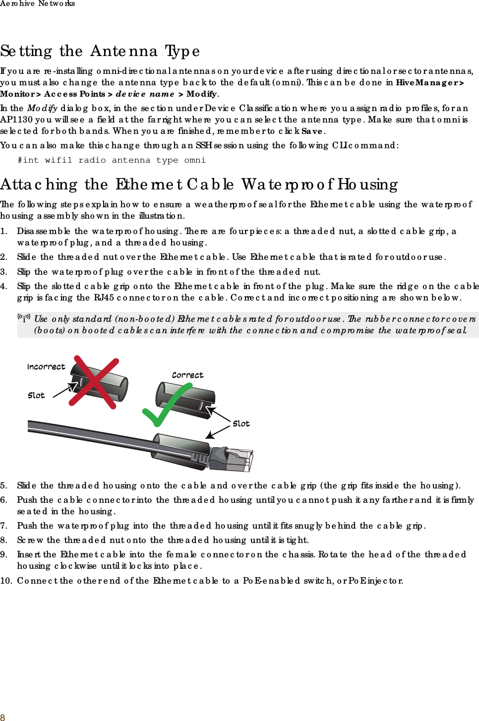
Installation Guide Updated 10/19/2015
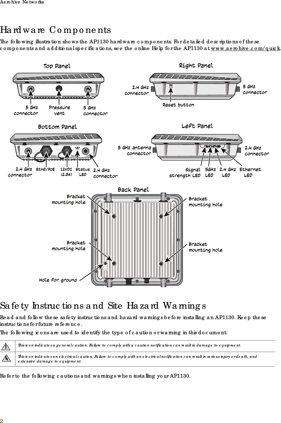
P/N 330205, Rev. A 1®AP1130 Installation GuideThe AP1130 is a multi-channel wireless access point with a watertight chassis that can be deployed in virtually any outdoor setting, including extreme environments. This guide explains how to install the AP1130 on a pole or flat surface in virtually any outdoor setting, and connect it to Aerohive HiveManager Network Management over the network. To register, get the latest product documentation, see compliance information, and download software updates, visit www.aerohive.com/support. For detailed hardware information about this device, visit www.aerohive.com/quick.FCC and IC statements can be found on page 12.Kit Contents, Required Accessories, and ToolsThe AP1130 kit includes the items shown below.To install your AP1130, you will need the following accessories (ordered separately) and tools:• Two 2.4 GHz antennas•Two 5 GHz antennas • A switch that provides PoE power, or a PoE provisioning device, a DC backup battery (requires theDC power cable accessory, part number AH-ACC-1130-CBL-DC), or solar panel• A shielded cat5 Ethernet cable rated for outdoor use; length not to exceed 328 feet (100 m)• PoE Injector (optional).• Crosshead screwdriver for pan head screws and Reset button cover• Flat blade screwdriver to tighten the hose clamp• Security Torx (pin-in-Torx) screwdriver for the captive screws in the mounting bracketBracket (1)AP1130 chassisFive pan head machine screws with washers for pole mount and ground in bag labelled “POLE MOUNT & GROUNDING”Four pan head wall mount screws in the bag labeled “WALL MOUNT”Hose clampGround cable (1)Waterproof Ethernet housing
Aerohive Networks2Hardware ComponentsThe following illustration shows the AP1130 hardware components. For detailed descriptions of these components and additional specifications, see the online Help for the AP1130 at www.aerohive.com/quick.Safety Instructions and Site Hazard WarningsRead and follow these safety instructions and hazard warnings before installing an AP1130. Keep these instructions for future reference.The following icons are used to identify the type of caution or warning in this document:Refer to the following cautions and warnings when installing your AP1130.This icon indicates a general caution. Failure to comply with a caution notification can result in damage to equipment.This icon indicates an electrical caution. Failure to comply with an electrical notification can result in serious injury or death, and extensive damage to equipment.5GHz (0)                                                                                                                                                                                           5GHz (1)2.4GHz (0)                                                                          Eth0/PoE+                                         12VDC (2.0A)                       2.4 GHz (1)StatusBracket mounting holeBracket mounting holeBracket mounting holeBracket mounting holeHole for groundReset buttonResetTop PanelBottom PanelRight PanelLeft PanelBack Panel5 GHz connector5 GHz antenna connector5 GHz connector5 GHz connectorPressureventEth0/PoE 12VDC (2.0A)StatusLED2.4 GHz connector2.4 GHz connector2.4 GHz connector2.4 GHz  connector5GHz  2.4 GHz  EthernetLED     LED        LEDSignal strength LED
Aerohive Networks3Installing the AP1130You can mount the AP1130 outdoors on a horizontal or vertical pole, or on an indoor or outdoor wall. You can adjust the orientation of the AP1130 for optimum radio transmission. For example, you can mount the AP1130 on a non-penetrating roof stand or to a Winegard bracket, often used for mounting satellite dishes. To provide unobstructed RF coverage, mount the AP1130 in a relatively open area on a pole, mast, of flat surface so that the antennas have at least a three-foot clearance from any nearby obstructions.Aerohive devices must be installed by a professional installer who is certified to install these types of devices and to ensure that they are properly grounded and meet applicable local and national electrical codes. In the United States of America, wireless devices with N-type connectors must be installed by a professional installer to satisfy the FCC antenna requirement for a unique connection method.Do not install the device in an environment where the operating ambient temperature might exceed the recommended ranges.To comply with radio frequency exposure limits, do not place this antenna within 26.5" (67 cm) of any people or animals.Changes or modifications made to this device that are not expressly approved by the party responsible for compliance could void the user's authority to operate the equipment.For reliable connections in all conditions, especially in wet and windy locations, you must use the Ethernet cable housing.For products available in the USA/Canada market, for the 2.4 GHz band, only channels 1-11 can be operated. Selection of other channels is not possible.Use only attachments and accessories specified by Aerohive.These devices are not designed or approved for use with power lines other than 110-120V or 220-240 volts, 50/60 Hz, single phase (depending on the country in which they are being used). Attempting to use these devices on non-approved power lines may have hazardous consequences.Do not plug these devices into a filtered power strip or AC line filter.These devices are not intended for use by persons (including children) with reduced physical, sensory, or mental capabilities, or with lack of experience of knowledge unless they are given supervision or instruction concerning use of the devices by a person who is responsible for their safety. Children should be supervised to ensure that they do not play with the devices.Electrostatic discharge (ESD) can damage equipment and impair electrical circuitry. ESD damage occurs when electronic components are improperly handled and can result in complete or intermittent failures. Be sure to follow ESD-prevention procedures when handling electronic components.Disconnect all power by turning off the power switch and unplugging the power cord before installing or removing a device, or working near power supplies.Reliable grounding of equipment should be maintained. Particular attention should be given to supply connections other than direct connections to the branch circuit (e.g. use of power strips.)To protect the AP1130 from lightning, do not place it at the highest point of a building or structure.During operation, the surfaces of the AP1130 can become hot. Use caution when handling.Make sure that the AP1130 is connected to a suitably installed ground conductor. Contact the appropriate electrical inspection authority if you are uncertain that suitable grounding is available.Do not locate the AP1130 enclosure near overhead power lines or other electric light or power circuits, or where it can come into contact with such circuits. During installation, exercise extreme care not to come into contact with these circuits, which can cause serious injury or death. For proper installation and grounding of the product, refer to national and local electrical codes: NFPA (National Fire Protection Association) 70, National Electrical Code Article 810 (U.S.); Canadian Electrical Code, Part I, CSA 22.1 and Section 54 (Canada); and if local or national electrical codes are not available, refer to IEC (International Electrotechnical Commission) 364, Part 1 through 7 (other countries).Do not connect or disconnect antennas or cables from the AP1130 during periods of lightning activity.Per FCC requirements, do not place this antenna within 26.5" (70 cm) of any people or animals.
Aerohive Networks4Make sure that you have all the materials and tools necessary, and familiarize yourself with the safety and site hazard warnings before you install the device. The following figure shows a typical rooftop installation.Power ConnectionsIn most cases, you can connect an Ethernet cable directly from your AP1130 to a PoE-enabled switch, or to a PoE injector inside the building. You can also connect your AP1130 to a DC power source, such as a battery backup or solar panel. If you are not using a PoE-enabled switch, you must connect to an intermediary PoE injector, then to your switch. In cases where your AP1130 is located a significant distance from the building, you can install an outdoor waterproof PoE injector, available as an accessory. For more information about Aerohive accessories, contact your Aerohive sales representative.You muIMPORTANT WATERPROOF CAUTIONS: It is extremely important that you have either A) the antennas tightly installed, or B) antenna connector caps tightly installed on the antenna connectors when antennas are not being used to ensure the unit is waterproof. You can order antenna connector caps from Aerohive (AH-ACC-1130-CVR-RF).You must install the waterproof housing on the RJ45 connector to ensure a waterproof connection. If you are not using Ethernet cable, always keep the cover on the RJ45 connector to ensure the device is waterproof.The DC connector cap must be installed when the connector is not in use to ensure the device is waterproof.There are no serviceable parts inside the AP1130. Do not open the chassis for any reason. Opening the chassis will compromise the waterproof seal and void the warranty.For best performance, deploy AP1130 devices at least 100 feet (30.5 m) apart from each other.Shielded Ethernet cableGround wire connected to grounded poleN-type outdoor antennasThe AP1130 mountedon a grounded vertical pole. A shielded Ethernet cable provides both the network connection and powerthrough PoE. The AP1130 ground wire is connected to the grounded pole.Access through roof to internal connection point.
Aerohive Networks5Vertical or Horizontal Pole MountThe following steps explain how to mount the AP1130 on a vertical or horizontal pole. The pole can be from 1.0 - 2.75 inches (25 to 70 mm) diameter. You can also order a hose strap that will fit poles with a 3" to 15" (76 to 381 mm) diameter (AH-ACC-1130-STRP-3-15).1. Attach the bracket to the back of the unit for either a vertical or horizontal mount using the four mounting bolts with attached washers. Tighten the bolts with a crosshead screwdriver. Be sure to use the bolts with washers from the plastic bag labeled “Pole Mount and Grounding” as they secure the bracket tightly to the back of the device for pole mounts.2. Thread the open end of the hose strap through the two tabs on the mounting bracket.The embossed arrows on the bracket should be pointing up for both a vertical pole mount, and a vertical surface (wall) mount.Bracket installed for a vertical pole mount Bracket installed for a horizontal pole mountSlip large ends of bracket keyholes over mounting screws.Slide bracket up until screws are in the narrow portion of the keyhole.Tighten the locking screws to secure the bracket.Locking screw
Aerohive Networks63. Fit the hose strap around the pole and tighten the clamp with a 1/4” (2 cm) slotted screwdriver or a 5/16” (8 mm) drive socket (or nut) driver.4. Insert the fifth bolt with washer through the terminal on one end of the ground cable. Thread the bolt into the ground hole on the back of the unit and tighten it until the ground terminal is secure. 5. Connect the other end of the cable to an appropriate ground.Correct Alignment of Device to EarthFor both vertical and horizontal installations (such as the arm of a street light), make sure that the face of the device is perpendicular to Earth for optimal RF coverage and to comply with FCC regulations.Thread the strap through the slots in the mounting bracket (a vertical pole mount is shown). PoleTighten the clamp around the pole.Grounding lug45Grounding nutCable terminalPoleEarthVertical mount                Horizontal mount
Aerohive Networks7Flat Surface Installation The following steps explain how to mount the AP1130 on a flat surface or wall. You will need the mounting bracket and the four bolts without washers in the plastic bag labeled “Wall Mount”. You will also need four mounting screws and wall mount anchors (not included) that are appropriate for the wall type where you are installing the unit.1. Use the bracket as a template to mark the location of the mounting holes on the wall.2. Drill a hole into the wall at each mark. Attach the bracket to the wall using the appropriate mounting screws and anchors for the wall type. 3. Insert the bolts without washers from the plastic bag labeled “Wall Mount” into the four mounting holes on the back of the device. 4. Insert the heads of the bolts on the device into the large end of the bracket keyholes and slide the device down until the bolts rest in the narrow end of the keyholes. 5. Tighten the locking screws to secure the device to the wall mount bracket.6. Connect the terminal on one end of the grounding cable to the grounding lug on the device and connect the other end of the cable to an appropriate ground, as shown in Step 5 on page 6.Attaching External AntennasOnce you have grounded your AP1130, you are ready to connect the antennas.  Use antennas that fit the N-type antenna connectors on the top and bottom of the AP1130. The two connectors on the bottom of the unit are for 2.4 GHz antennas, and the two on the top of the unit are for 5 GHz antennas (device and antennas are labeled).Screw the antennas onto the antenna connectors, turning them clockwise and tightening with your fingers until they are secure. When you are not using the antennas, always cover the antenna connectors with antenna connector caps to protect the connectors and meet IP67 compliance requirements. If you are not installing the device on a concrete wall, you can use threaded screws and plastic wall anchors (not supplied) to mount the device.It is extremely important to properly ground your device to complete your installation.Finger-tighten the antennas to the connectors only, do not use tools or your wrist. If you over-tighten the antennas on the connectors, you can compromise the waterproof seal.In the United States of America, wireless devices with N-type connectors must be installed by a professional installer to satisfy FCC antenna requirements for a unique connection method.Use the bracket as a template to mark where to drill the holes in the wall.Wall
Aerohive Networks8Setting the Antenna TypeIf you are re-installing omni-directional antennas on your device after using directional or sector antennas, you must also change the antenna type back to the default (omni). This can be done in HiveManager > Monitor > Access Points > device name > Modify.In the Modify dialog box, in the section under Device Classification where you assign radio profiles, for an AP1130 you will see a field at the far right where you can select the antenna type. Make sure that omni is selected for both bands. When you are finished, remember to click Save.You can also make this change through an SSH session using the following CLI command:#int wifi1 radio antenna type omniAttaching the Ethernet Cable Waterproof HousingThe following steps explain how to ensure a weatherproof seal for the Ethernet cable using the waterproof housing assembly shown in the illustration.1. Disassemble the waterproof housing. There are four pieces: a threaded nut, a slotted cable grip, a waterproof plug, and a threaded housing. 2. Slide the threaded nut over the Ethernet cable. Use Ethernet cable that is rated for outdoor use.3. Slip the waterproof plug over the cable in front of the threaded nut. 4. Slip the slotted cable grip onto the Ethernet cable in front of the plug. Make sure the ridge on the cable grip is facing the RJ45 connector on the cable. Correct and incorrect positioning are shown below.5. Slide the threaded housing onto the cable and over the cable grip (the grip fits inside the housing). 6. Push the cable connector into the threaded housing until you cannot push it any farther and it is firmly seated in the housing.7. Push the waterproof plug into the threaded housing until it fits snugly behind the cable grip.8. Screw the threaded nut onto the threaded housing until it is tight. 9. Insert the Ethernet cable into the female connector on the chassis. Rotate the head of the threaded housing clockwise until it locks into place.10. Connect the other end of the Ethernet cable to a PoE-enabled switch, or PoE injector.Use only standard (non-booted) Ethernet cables rated for outdoor use. The rubber connector covers (boots) on booted cables can interfere with the connection and compromise the waterproof seal.SlotSlotCorrectIncorrect
Aerohive Networks9Accessing the Reset ButtonThe Reset button is located on the right side panel. To access it, remove the screw that covers the button. Use a paper clip or similar tool to push the button in between 1 and 5 seconds to reboot the device, or for 5 seconds or more to return the device to the factory default settings. When you are done, replace the cover screw firmly to cover the access point and restore the device to its weatherproof state.Using the Antenna Alignment BuzzerThe AP1130 has an audible buzzer signal to help you align antennas for the best coverage. By default, the buzzer is enabled and will beep with changing frequency based on the signal strengths that are determined during the alignment process. The better the signal strength, the more frequent the beeps.You can enable, configure, and disable the buzzer using the following CLI command through a Console connection to the device.CLI Syntax: exec antenna-alignment interface <wifix> peer <mac_addr> [count [numbers]] [interval [numbers]] [text-size [numbers]] [beep [static]|[adaptive]|[disable]]•beep: Set the antenna buzzer mode, which the device uses to indicate the quality of antenna alignment by increasing the frequency of audible beeps as the signal strength improves. The default is adaptive.•static: Set the antenna buzzer to beep when the signal strength falls between 0 and 80 dB.•adaptive: Set the antenna buzzer to beep based on the signal strengths that are determined during the alignment process.•disable: Disable the antenna buzzer.AP1130 LEDsThe AP1130 has a Status LED on the bottom of the unit, and a Signal Strength LED and three connectivity LEDs on the right panel. The LED colors and what they indicate are described below.Status LED•Dark: no power to the device.•Amber (steady): the device has not made a CAPWAP connection.•Amber (flashing): the device is undergoing a firmware upgrade.•White: the device is operating properly.Signal Strength LED:•Dark: no signal or not in use.•Amber: the signal is weak (no neighbor has been found with a signal strength greater than -60 dBm).Step 5. Threaded housingConnectorStep 2. Threaded nutStep 4. slotted cable gripStep 3. Waterproof plugThe slot must be at the connector end of the grip.Reset button
Aerohive Networks10•White: the signal is strong (neighbor or neighbors found with signal strengths greater than -60 dBm).5GHz LED:•Green (steady): The connection is functioning as backhaul with a neighbor.•Green (flashing): The connection is functioning as backhaul with no neighbor.•Dark: there is no connection.2.4 GHz LED:•Green (steady): The connection is functioning as backhaul with a neighbor.•Green (flashing): The connection is functioning as backhaul with no neighbor.•Dark: there is no connection.Eth LED:•Green (steady): The connection is functioning as backhaul with a neighbor.•Green (flashing): The connection is functioning as backhaul with no neighbor.•Dark: there is no connection.PoE and Ethernet ProtectionIn most cases, you can connect an Ethernet cable directly from the AP1130 to a PoE-enabled switch or to a PoE injector inside the building. In some cases, you might need to install an outdoor, waterproof PoE injector.The AP1130 and outdoor PoE injectors have built-in surge protection to guard against lightning strikes. However, the network where the Ethernet cable enters the building requires protection as well. To preventthe indoor network from power surges caused by lightning, place an Ethernet protector inline between the AP and the rest of the network. Use the following steps:1. Attach the Ethernet protection device to the building at the entry point of the shielded Ethernet cable from the AP1130.2. Make the following connections, as shown in the illustration:• Ground the device by running a wire from the grounding stud to a grounded object, such as a water pipe, gas pipe, or grounding rod.• Connect the shielded Ethernet cable from the port labeled “Equipment Side” to the network.Connecting to the NetworkThe final step to the installation is to connect the AP to the network so that it can form a CAPWAP (Control and Provisioning of Wireless Access Points) connection to HiveManager. CAPWAP is a protocol that access points use to contact and communicate with a management device. After you connect the AP to an Ethernet network and power it on, it automatically attempts to get network settings through DHCP and contact HiveManager. The process typically takes about five minutes to complete. When you see the AP listed in the HiveManager GUI, the initial setup is complete and you can begin managing the AP with HiveManager.If the AP does not appear in HiveManager after about ten minutes, read the following sections to understand how the AP tries to contact HiveManager and how you can help establish the connection.To a grounded object Grounding wire Ethernet ProtectorShielded Ethernet cableTo a switch, PoE switch, or indoor PoE injector inline to the network.To the AP1130 or to an outdoor PoE injector inline to the AP1130Ethernet cable
Aerohive Networks11Connecting to HiveManagerBy default, an AP acts as a DHCP client, and gets network settings automatically from a DHCP server. The AP then acts as a CAPWAP client and sends CAPWAP Discovery messages until HiveManager, acting as the CAPWAP server, responds. When an AP goes on line for the first time, and there is no CAPWAP server configuration entered manually or received as a DHCP option, it progresses through the following cycle of CAPWAP connection attempts.1. The AP tries to connect to HiveManager using the default name hivemanager.<local_domain>:12222, where <local_domain> is the domain name supplied by a DHCP server, and 12222 is the UDP port number. If there is a DNS server to resolve the domain name to an IP address, the AP and HiveManager can form a secure CAPWAP connection on port 12222. If the AP cannot connect on port 12222, it tries to reach HiveManager using TCP port 80: hivemanager.<local_domain>:80.2. If the DNS server cannot resolve the domain name to an IP address, the AP broadcasts CAPWAP Discovery Request messages on its local subnet. If HiveManager is on the local network and responds with a Discovery Response message, they perform a DTLS (Datagram Transport Layer Security) handshake to establish a secure CAPWAP connection.3. If the first two searches are not successful, the AP tries to contact HiveManager Online at redirector.aerohive.com:12222. If the redirection server has a serial number for the AP in its ACL (access control list), it responds and they form a secure CAPWAP connection. If the AP cannot make a CAPWAP connection to HiveManager Online on UDP port 12222, it tries to reach it on TCP port 80. If that is not successful, the AP returns to the original search through a DNS lookup and repeats the cycle.If an AP forms a CAPWAP connection with the redirection server and its serial number or MAC address has been assigned to a previously created VHM, a physical HiveManager appliance, or a HiveManager Virtual Appliance, the redirection server automatically redirects the CAPWAP connection to that HiveManager instance by sending the AP1130 the HiveManager domain name or IP address as its new CAPWAP server. If the AP is currently using HTTP and it will be redirected to a HiveManager Online VHM, the redirection server also sends it the configuration it needs to continue using HTTP. Similarly, if the AP is accessing the network through an HTTP proxy server, the redirection server also saves those settings on the AP so it can reach the HiveManager Online VHM using HTTP through the HTTP proxy server.312The AP tries to connect to HiveManager using hivemanager.<local_domain>:12222 If there is a DNS server to resolve the domain name to an IP address, the AP and HiveManager form a secure CAPWAP connection on port 12222. If they cannot connect on port 12222, the AP tries TCP port 80:  hivemanager.<local_domain>:80If the DNS server cannot resolve the domain name to an IP address, the AP broadcasts CAPWAP Discovery messages on its local subnet. If HiveManager is on the local network and responds, a secure CAPWAP connection is made.If step 2 does not work, the AP tries to contact HiveManager Online at redirector.aerohive.com:12222. If the redirection server has the serial number for the AP it responds and a CAPWAP connection is made. If the AP cannot connect on UDP port 12222, it tries TCP port 80. If this is unsuccessful, the AP returns to step 1.HiveManager or HiveManager Virtual ApplianceHiveManager Online
Aerohive Networks12If the redirection server must redirect the AP to a standalone HiveManager appliance or HiveManager Virtual Appliance, then you must configure the connection settings on the redirection server that you want it to push to the AP to make that connection. The AP first uses whatever settings are configured on it to reach the redirection server, which could be on the other side of an HTTP proxy server or firewall that only permits outbound HTTP traffic. Then the redirection server might send the AP different settings so the it can reach a standalone HiveManager instance, which could be on the same side of the HTTP proxy server or firewall as the AP and therefore requires different connection parameters.If the AP serial number or MAC address is in the redirection server but the VHM has not yet been created, or the connection settings of the standalone HiveManager have not yet been configured on the redirection server, then the AP remains in the redirection server. The HiveManager admin must manually reassign it later to the appropriate HiveManager instance.Where to Find More InformationTechnical Documentation: Aerohive provides various technical documents for its products. For information about CLI commands, see the CLI reference guides available in HTML format. For information about HiveManager and AP hardware and software topics, see the HiveManager Help system, or visit www.aerohive.com/quick. To access product documentation, visit www.aerohive.com/techdocs.HiveManager Help System: The HiveManager Help system contains a wealth of information about all the features you can configure through HiveManager. To access it, click the Help icon in the upper right corner of the GUI. A Help topic that pertains to the currently active GUI page appears. Use the table of contents to browse the Help system or the search tool to find information about a specific subject.Support Site: Access technical support services, documentation, and software at www.aerohive.com/support/login.html. After registering for an account, you will receive a user name and password to enter when logging in. You can contact Support for assistance through the web site or by phone (+1 408.510.6100 or 866.365.9918).Training: Aerohive offers courses covering the Aerohive cooperative control concepts, the installation and configuration of Aerohive products, and how to troubleshoot issues and optimize performance. For more information, visit www.aerohive.com/support/training.html.Aerohive also offers CBT (computer-based training) modules. CBTs are online Flash tutorials that explain Aerohive concepts and walk you through configuration procedures step by step. You can use CBTs to familiarize yourself with the HiveManager GUI and learn how to configure HiveAPs. Aerohive CBTs are available for free online at www.aerohive.com/techdocs.Federal Communication Commission Interference StatementThis equipment has been tested and found to comply with the limits for a Class B digital device, pursuant to Part 15 of the FCC Rules. These limits are designed to provide reasonable protection against harmful interference in a residential installation. This equipment generates, uses and can radiate radio frequency energy and, if not installed and used in accordance with the instructions, may cause harmful interference to radio communications. However, there is no guarantee that interference will not occur in a particular installation. If this equipment does cause harmful interference to radio or television reception, which can be determined by turning the equipment off and on, the user is encouraged to try to correct the interference by one of the following measures:• Reorient or relocate the receiving antenna.• Increase the separation between the equipment and receiver.• Connect the equipment into an outlet on a circuit different from that to which the receiver is connected.•Consult the dealer or an experienced radio/TV technician for help.FCC Caution: Any changes or modifications not expressly approved by the party responsible for compliance could void the user’s authority to operate this equipment.This device complies with Part 15 of the FCC Rules. Operation is subject to the following two conditions: (1) This device may not cause harmful interference, and (2) this device must accept any interference received, including interference that may cause undesired operation.For products available in the USA and Canada, only channels 1~11 can be operated. Selection of other channels is not possible.This device and its antennas must not be co-located or operating in conjunction with any other antenna or transmitter except in accordance with FCC multi-transmitter product procedures.IMPORTANT NOTE: FCC Radiation Exposure Statement:This equipment complies with FCC radiation exposure limits set forth for an uncontrolled environment. This equipment should be installed and operated with a minimum distance 15.75" (40 cm) between the radiator and your body.FCC NOTICE: To comply with FCC part 15 rules in the United States, the system must be professionally installed to ensure compliance with the Part 15 certification. It is the responsibility of the operator and professional installer to ensure that only certified systems are deployed in the United States. The use of the system in any other combination (such as co-located antennas transmitting the same information) is expressly forbidden.
Aerohive Networks13Industry Canada (IC) StatementThis device complies with Industry Canada license-exempt RSS standard(s). Operation is subject to the following two conditions: (1) this device may not cause interference, and (2) this device must accept any interference, including interference that may cause undesired operation of the device.Le présent appareil est conforme aux CNR d'Industrie Canada applicables aux appareils radio exempts de licence. L'exploitation est autorisée aux deux conditions suivantes: (1) l'appareil ne doit pas produire de brouillage, et (2) l'utilisateur de l'appareil doit accepter tout brouillage radioélectrique subi, même si le brouillage est susceptible d'en compromettre le fonctionnement.For products available in the USA and Canada, only channel 1~11 can be operated. Selection of other channels is not possible.Pour les produits disponibles aux États-Unis / Canada du marché, seul le canal 1 à 11 peuvent être exploités. Sélection d'autres canaux n'est pas possible.This device and its antennas must not be co-located or operating in conjunction with any other antenna or transmitter except in accordance with IC multi-transmitter product procedures.Cet appareil et son antenne (s) ne doit pas être co-localisés ou fonctionnement en association avec une autre antenne ou transmetteur.Dynamic Frequency Selection (DFS) for devices operating in the bands 5250- 5350 MHz,5470-5600 MHz and 5650-5725 MHzSélection dynamique de fréquences (DFS) pour les dispositifs fonctionnant dans les bandes 5250-5350 MHz, 5470-5600 MHz et 5650-5725 MHz.The maximum antenna gain permitted (for devices in the bands 5250-5350 MHz and 5470-5725 MHz) to comply with the e.i.r.p. limit.le gain maximal d’antenne permis pour les dispositifs utilisant les bandes 5250-5350 MHz et 5470-5725 MHz doit se conformer à la limite de p.i.r.e.Users should also be advised that high-power radars are allocated as primary users (i.e. priority users) of the bands 5250-5350 MHz and 5650-5850 MHz and that these radars could cause interference and/or damage to LE-LAN devices.De plus, les utilisateurs devraient aussi être avisés que les utilisateurs de radars de haute puissance sont désignés utilisateurs principaux (c.-à-d., qu’ils ont la priorité) pour les bandes 5250-5350 MHz et 5650-5850 MHz et que ces radars pourraient causer du brouillage et/ou des dommages aux dispositifs LAN-EL.IMPORTANT NOTE: IC Radiation Exposure Statement:This equipment complies with IC RSS-102 radiation exposure limits set forth for an uncontrolled environment. This equipment should be installed and operated with minimum distance 67 cm (27.5") between the radiator and your body.Cet équipement est conforme aux limites d'exposition aux rayonnements IC établies pour un environnement non contrôlé. Cet équipement doit être installé et utilisé avec un minimum de 70 cm de distance entre la source de rayonnement et votre corps.This radio transmitter (AP1130) has been approved by Industry Canada to operate with the antenna types listed below with the maximum permissible gain and required antenna impedance for each antenna type indicated. Antenna types not included in this list, having a gain greater than the maximum gain indicated for that type, are strictly prohibited for use with this device.Le présent émetteur radio (AP1130) a été approuvé par Industrie Canada pour fonctionner avec les types d'antenne énumérés ci-dessous et ayant un gain admissible maximal et l'impédance requise pour chaque type d'antenne. Les types d'antenne non inclus dans cette liste, ou dont le gain est supérieur au gain maximal indiqué, sont strictement interdits pour l'exploitation de l'émetteur.Under Industry Canada regulations, this radio transmitter may only operate using an antenna of a type and maximum (or lesser) gain approved for the transmitter by Industry Canada. To reduce potential radio interference to other users, the antenna type and its gain should be so chosen that the equivalent isotropically radiated power (e.i.r.p.) is not more than that necessary for successful communication.Conformément à la réglementation d’Industrie Canada, le présent émetteur radio peut fonctionner avec une antenna d’un type et d’un gain maximal (ou inférieur) approuvé pour l’émetteur par Industrie Canada. Dans le but de réduire les risques de brouillage radioélectrique à l’intention des autres utlisateurs, il faut choisir le type d’antenne et son gain de sorte que la puissance isotrope rayonée équivalente (p.i.r.e) ne dépasse pas l’intensité necessaire à l’éstablissement d’une communcation satisfaisante..Conformément à la réglementation d'Industrie Canada, le présent émetteur radio peut fonctionner avec une antenne d'un type et d'un gain maximal (ou inférieur) approuvé pour l'émetteur par Industrie Canada. Dans le but de réduire les risques de brouillage radioélectrique à l'intention des autres utilisateurs, il faut choisir le type d'antenne et son gain de sorte que la puissance isotrope rayonnée équivalente (p.i.r.e.) ne dépasse pas l'intensité nécessaire à l'établissement d'une communication satisfaisante.Ant.Brand Model Antenna Type Connector Antenna Gain (dBi) Cable Loss(dBi) True Gain(dBi)2.4GHz 5GHz 2.4GHz 5GHz 2.4GHz 5GHz1WNCVeab-n01 Dipole antenna N Type 4.38 - - - - -2WNCVeab-n01 Dipole antenna N Type - 5.5 - - - -3 ARE ARE14-220340 Dual band sector antenna N Type 5.0 6.0 - - - -
Aerohive Networks14© 2015 Aerohive Networks, Inc.Aerohive is a U.S. registered trademark of Aerohive Networks, Inc.P/N 330120-02 Rev. A

Navigation menu