Agere Systems Nederland WLPCE2411R Wireless LAN PC Card User Manual ORiNOCO Outdoor Antenna Installation Guide
Agere Systems Nederland B.V. Wireless LAN PC Card ORiNOCO Outdoor Antenna Installation Guide
Contents
- 1. Owners Manual
- 2. User manual
User manual
About this Document
The product described in this book is a licensed product of Lucent
Technologies Inc.
• ORiNOCO, WaveLAN, WaveACCESS, WavePOINT and
WaveMANAGER are registered trademarks or trademarks of Lucent
Technologies Inc.
• Microsoft MS-Windows and MS-DOS are registered trademarks or
trademarks of Microsoft Corporation.
• Adobe Acrobat is a registered trademark of Adobe Systems Inc.
All other brand and product names are trademarks or registered trademarks of
their respective holders.
This Document was created by:
Lucent Technologies Nederland B.V.
Wireless Communications & Networking Division (WCND)
P.O. Box 755
3430 AT Nieuwegein
The Netherlands
An electronic copy of this document is also available on the enclosed
software CD-ROM. Updates of this document can be downloaded from the
ORiNOCO Library on the World Wide Web at http://www.lucent.com/orinoco.
To view or print the electronic document, in Adobe’s Portable Document
Format (PDF), you will need the Adobe Acrobat Reader®, included on the
enclosed Software CD-ROM.
Alternatively, consult the Adobe website at: http://www.adobe.com.
November 6, 2000
It is the policy of Lucent Technologies to improve products as new
technology, components, software, and firmware become available. Lucent
Technologies, therefore, reserves the right to change specifications without
prior notice.
All features, functions, and operations described herein may not be marketed
by Lucent Technologies in all parts of the world. In some instances, drawings
are of equipment prototypes. Therefore, before using this document, consult
your Lucent Technologies representative or Lucent Technologies office for
information that is applicable and current.
Copyright ©2000 Lucent Technologies Inc., All Rights Reserved
COV_ODC.fm Page 2 Monday, November 6, 2000 1:22 PM
ORiNOCO Outdoor Antenna Installation Guide i
1 Welcome 1-1
About This Guide 1-1
■Who Should Use This Guide 1-1
■Finding Additional Information 1-2
About ORiNOCO Outdoor Router 1-4
2 Preparing for Installation 2-1
Site Prerequisites 2-1
Overview of the Indoor Installation 2-2
■Outdoor Router Hardware 2-2
■Cable System 2-5
Overview of the Outdoor Installation 2-8
■Antenna Placement 2-8
■Antenna Mast/Wall Bracket 2-11
■Grounding System 2-12
■Antenna Cable Routing 2-14
Before Climbing the Roof... 2-15
3 Determine Range & Clearance 3-1
Introduction 3-1
Determine the Outdoor Range 3-2
■Determine the Maximum Range 3-3
■Determine the Cable Factor 3-7
■Determine the Clearance Factor 3-8
Table of Contents
ii ORiNOCO Outdoor Antenna Installation Guide
Examples 3-13
■Point-to-Point Links 3-13
■Point-to-MultiPoint Links 3-15
4 Installing the Antenna 4-1
Planning Antenna Installation 4-1
■Safety Precautions 4-1
■Installation Overview 4-3
Mounting the Antenna 4-5
Connecting the Antenna Cable 4-6
■Sealing the Cable Connectors 4-7
A The Antenna Cabling System A-1
The Outdoor Cabling Components A-1
■Selecting the Correct Connector-Type A-2
ORiNOCO Cable Assembly A-6
ORiNOCO Surge Arrester A-7
Low-Loss Antenna Cable A-9
B 14 dBi Directional Antenna B-1
General Description B-1
■Contents of the Antenna Box B-1
■Mounting the Directional Antenna B-1
C 7 dBi Omni-Directional Base Station Antenna C-1
Hardware Specifications C-1
■Mounting the Omni-directional Antenna C-1

ORiNOCO Outdoor Antenna Installation Guide iii
D 10 dBi Omni-Directional Base Station Antenna D-1
Hardware Specifications D-1
■Mounting Instructions D-1
E 12 dBi Directional Wide Angle Antenna E-1
Hardware Specifications E-1
■Mounting Instructions E-1
F 24 dBi Directional Parabolic Grid Antenna F-1
Hardware Specifications F-1
■Kit Contents F-2
■Assembling the Antenna F-2
■Mounting the Antenna F-4


Contents
1
Welcome
About This Guide 1-1
Who Should Use This Guide 1-1
Finding Additional Information 1-2
■Installing Outdoor Router Hardware 1-2
■Configuration and Management 1-2
■Context-Sensitive Help 1-3
■Hardware Specifications 1-3
■Additional files on your Software CD-ROM 1-3
■Other Sources of Information 1-3
About ORiNOCO Outdoor Router 1-4
■ORiNOCO Remote Outdoor Router 1-4
■ORiNOCO Central Outdoor Router 1-5
■Upgrading the ORiNOCO Outdoor Router 1-6

ORiNOCO Outdoor Antenna Installation Guide 1-1
Welcome
About This Guide
This ORiNOCO Outdoor Antenna Installation Guide explains how to install and
set-up an outdoor antenna installation based on ORiNOCO PC Cards that will
be used in combination with:
■ORiNOCO Outdoor Router products1
■ORiNOCO Client products
There is also a chapter about verifying the wireless link quality and correcting
problems that might arise during installation or operation.
This guide does not explain how to erect antenna masts, or how to install a
safety grounding system. These are pre-requisites that must be in place before
the directional antenna is installed.
Who Should Use This Guide
The installation of Outdoor Antenna Links requires technical expertise. At the
very least, you should be able to:
■Install and configure the network components, such as the Outdoor Router
and the ORiNOCO LAN administrator’s station.
■Understand or have a working knowledge of the installation procedures for
network operating systems under Microsoft Windows 95/98 and/or Microsoft
Windows NT.
■Mount the outdoor antenna and surge arrester. Lucent Technologies
recommends that the installation is performed by a qualified antenna
installation service.
1 Formerly also referred to as WavePOINT-II PTP, WaveACCESS Link WP-II or WaveCAMPUS.
Welcome
About This Guide
1-2 ORiNOCO Outdoor Antenna Installation Guide
!DANGER:
The ORiNOCO Outdoor Router outdoor antennas are intended for
mounting on a roof, or the side of a building. Installation shall not be
attempted by someone who is not trained or experienced in this type of
work.The antenna has to be installed by a suitably trained professional
installation technician or a qualified antenna installation service. The site
pre-requisites have to be checked by a person familiar with the national
electrical code, and other regulations governing this type of installation.
Finding Additional Information
Installing Outdoor Router Hardware
ORiNOCO outdoor antenna installations are typically connected to
Outdoor Router devices. The hardware installation of these devices is described
in the Getting Started Guide that is included with each Outdoor Router unit.
Configuration and Management
The configuration and management of outdoor antenna links is controlled via the
OR Manager program; an MS-Windows based application that can be installed
on almost any computer running Windows 95, 98 or Windows NT (v4.0).
How to install this program is described in the Getting Started Guide that is
included with each Outdoor Router unit.
How to use the OR Manager program is described in:
■The “Context-Sensitive Help” as described below.
■The "ORiNOCO OR Manager - User’s Guide" provided on the software CD-
ROM that came with the Outdoor Router device (inserted inside the back-
side cover of the Getting Started Guide that came with your product).
■The "ORiNOCO OR Manager - User’s Guide" also describes how to monitor
the performance of your wireless network, and provides hints and scenarios
for troubleshooting performance degradation.
To view and/or print these documents, you will need to install the Adobe
Acrobat Reader provided on the software CD-ROM.
Welcome
About This Guide
ORiNOCO Outdoor Antenna Installation Guide 1-3
Context-Sensitive Help
Context-sensitive help for the OR Manager program is available by clicking the
“Help” button on the screen or pressing the function key.
Hardware Specifications
■Outdoor Router hardware specifications are described in the Getting Started
Guide that is shipped with each device.
■Radio Frequency specifications of the Outdoor Router are described in the
"ORiNOCO PC Card Getting Started".
■Hardware specifications for the outdoor antennas, the cabling system and
the ORiNOCO Surge Arrester are listed in Appendices of this guide.
Additional files on your Software CD-ROM
All software CD-ROMs (or diskettes) that came with your ORiNOCO products,
include a file called “readme.txt”. This file contains information about the
software version and/or drivers on the diskette.
NOTE:
You are advised to print and read the “readme.txt” file prior to installing
your ORiNOCO products, as it may contain additional information that
was not available when this document was printed.
Other Sources of Information
All documentation listed above can be downloaded from the ORiNOCO website
at: http://www.lucent.com/orinoco.
NOTE:
You are advised to visit the website at regular intervals for the latest
available information, documentation and software updates and other
ORiNOCO news.
F1
Welcome
About ORiNOCO Outdoor Router
1-4 ORiNOCO Outdoor Antenna Installation Guide
About ORiNOCO Outdoor Router
The ORiNOCO Outdoor Router enables you to setup a wireless system that
supports:
■“ORiNOCO Remote Outdoor Router” functionality, or
■“ORiNOCO Central Outdoor Router” functionality.
ORiNOCO Remote Outdoor Router
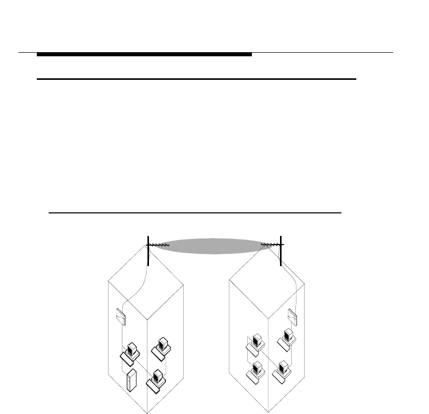
With two ORiNOCO Remote Outdoor Routers, it’s easy to setup a wireless
Point-to-Point link as pictured in Figure 1-1 below.
Figure 1-1 ORiNOCO Point-to-Point Link
The Point-to-Point (PTP) Link functionality enables you to setup a connection
between two locations as an alternative to:
■Leased lines in building-to-building connections, or
■Wired Ethernet backbones between AP-1000s in ‘hard-to-wire’
environments.
Welcome
About ORiNOCO Outdoor Router
ORiNOCO Outdoor Antenna Installation Guide 1-5
ORiNOCO Central Outdoor Router
If you wish to connect more than two buildings, you can choose to:
■Setup multiple Point-to-Point links, using multiple pairs of Remote Outdoor
Router systems, or
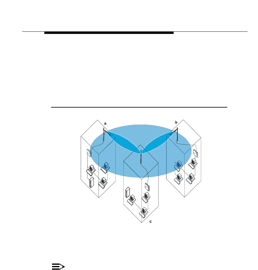
■Setup a single Point-to-Multipoint system using a single Central Outdoor
Router and multiple Remote Outdoor Routers as pictured in Figure 1-2
below.
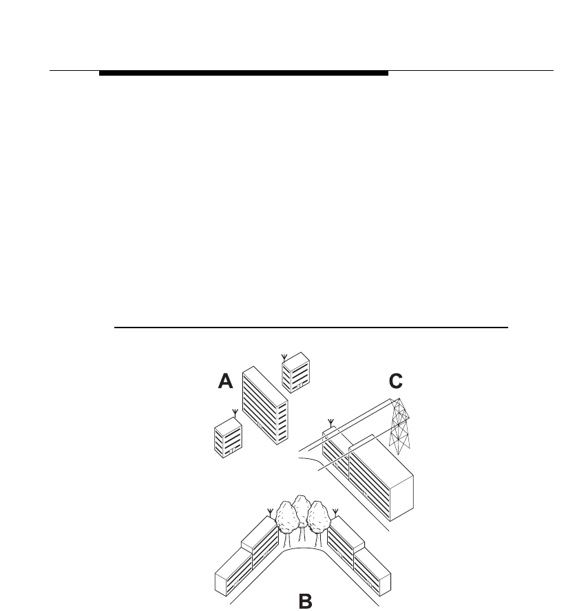
Figure 1-2 ORiNOCO Point-to-Multipoint Link
Looking at Figure 1-2 the system is designed as follows:
■The central building c is equipped with the Central Outdoor Router,
connected to either an omni-directional, or wide angle antenna.
■The two Remote buildings a and b have both been equipped with Remote
Outdoor Routers connected to directional antennas.
NOTE:
Subject to local radio regulations and legislation, the outdoor antenna
solutions described in this document may not be available in all parts of
the world. Consult Appendix G “Certified Outdoor Solutions” for more
information.

Welcome
About ORiNOCO Outdoor Router
1-6 ORiNOCO Outdoor Antenna Installation Guide
Upgrading the ORiNOCO Outdoor Router
If you wish to extend the features of previously purchased hardware you can
purchase dedicated Software License Kits to upgrade:
■AP-1000 into one of the ORiNOCO Outdoor Routers described on the
previous pages.
■Extend the features of a previously purchased ORiNOCO Outdoor Routers.
For more information about the software license upgrade program, please
consult:
■Your authorized ORiNOCO Reseller or local Lucent Technologies Sales
office for more information.
■The ORiNOCO website at: http://www.lucent.com/orinoco.
Contents
2
Preparing for Installation
Site Prerequisites 2-1
Overview of the Indoor Installation 2-2
Outdoor Router Hardware 2-2
■Outdoor Router 2-2
■Outdoor Router Client 2-4
Cable System 2-5
■Placement of the Surge Arrester 2-5
■Antenna Cable Route 2-6
Overview of the Outdoor Installation 2-8
Antenna Placement 2-8
Antenna Mast/Wall Bracket 2-11
■Tripod Mount 2-11
■Wall (Side) Mount 2-11
■Antenna Mast Requirements 2-11
Grounding System 2-12
■Antenna Alignment 2-12
■Antenna Polarization 2-13
Antenna Cable Routing 2-14

ORiNOCO Outdoor Antenna Installation Guide 2-1
Preparing for Installation
Site Prerequisites
Please review all requirements outlined within the sections listed below before
starting the installation procedure:
■Overview of the Indoor Installation (page 2-2)
■Overview of the Outdoor Installation (page 2-8)
■Before Climbing the Roof... (page 2-15)
Prior to climbing on the roof or any other area where you intend to install the
outdoor antenna, you are advised to:
■Verify you have arranged all safety measures for outdoor/rooftop installation
(see the “Safety Precautions” on page 4-1).
■Verify you have all equipment and tools required to install the outdoor
antennas.
■Install and verify proper operation of the equipment.
Preparing for Installation
Overview of the Indoor Installation
2-2 ORiNOCO Outdoor Antenna Installation Guide
Overview of the Indoor Installation
The indoor installation of the link will consist of the following components:
■Outdoor Router Hardware, and
■A Cable System.
Outdoor Router Hardware
There are two types of hardware installations to setup a wireless connection:
■The Outdoor Router, and
■The Outdoor Router Client.
Outdoor Router
To setup a point-to-point wireless connection between two Outdoor Routers, you
will need:
■Two ORiNOCO Outdoor Routers with PC Card, and
■Two antenna cable systems (see Appendix Appendix A “The Antenna
Cabling System”), and
■Two outdoor antenna’s.
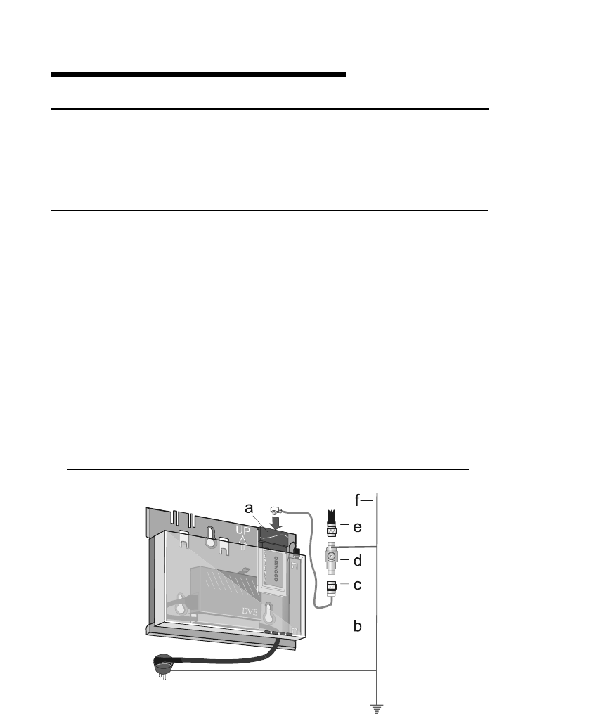
Figure 2-1 shows an overview of the hardware setup for this indoor installation.
Figure 2-1 Overview Indoor Installation of the Outdoor Router
Preparing for Installation
Overview of the Indoor Installation
ORiNOCO Outdoor Antenna Installation Guide 2-3
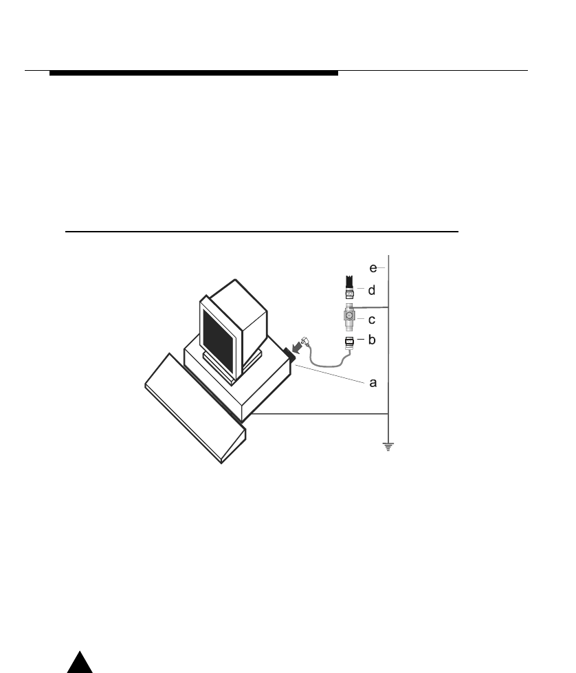
On each end of the wireless link you will need the following items as pictured in
Figure 2-1 on page 2-2:
a. The ORiNOCO PC Card (see “Selecting the Right Card & Cables” on
page G-3).
b. The Outdoor Router device that has been loaded with ORiNOCO
Outdoor Router software.
c. The Cable Assembly to connect the PC Card to the Surge Arrester.
d. A surge arrester to protect your sensitive ORiNOCO equipment from static
discharge and transients that may occur to your antenna.
e. A low-loss antenna cable to connect the indoor installation to the outdoor
antenna.
f. A grounding system as described in “Grounding System” on page 2-12.
!WARNING:
The ORiNOCO Outdoor Router, the ORiNOCO Surge Arrester and the
antenna mast must be connected to the same grounding system.
Placement of the Outdoor Router Hardware
The hardware of your ORiNOCO Outdoor Router device is designed for indoor
mounting and operation. The ideal location to install your Outdoor Router unit
must satisfy the following requirements:
■The location provides a connection to a grounding type AC wall outlet (100-
240 VAC), using the standard power cord as supplied with the unit.
The ground of the AC wall outlet must be connected to the same grounding
system as the ORiNOCO Surge Arrester and antenna mast (see “Grounding
System” on page 2-12).
■The location must allow for easily disconnecting the Outdoor Router unit
from the AC wall outlet.
■The location provides a connection to the network backbone that may either
be:
■The Ethernet LAN cable that connects it to a hub, bridge or directly into
a patch panel or
■The wireless connection via a second ORiNOCO PC Card that is
inserted into the other PC Card slot of the Outdoor Router device.
■The location is as close as possible to the point where the antenna cable will
enter the building (see also “Placement of the Surge Arrester” on page 2-5).
Preparing for Installation
Overview of the Indoor Installation
2-4 ORiNOCO Outdoor Antenna Installation Guide
Outdoor Router Client
To setup a wireless connection with the Outdoor Router Client, you will need:
■One PC Card,
■One Outdoor Router Client License Kit, and
■One antenna cabling system.
Figure 2-2 shows an overview of the hardware setup for this indoor installation.
Figure 2-2 Overview Indoor Installation Outdoor Router Client
On each end of the wireless link you will need the following items as pictured in
Figure 2-2:
a. The ORiNOCO PC Card (see “Selecting the Right Card & Cables” on
page G-3).
b. The Cable Assembly to connect the ORiNOCO PC Card (A) to the Surge
Arrester.
c. A surge arrester to protect your sensitive ORiNOCO equipment from static
discharge and transients that may occur to your antenna.
d. A low-loss antenna cable to connect the indoor installation to the outdoor
antenna.
e. A grounding systems as described in “Grounding System” on page 2-12.
!WARNING:
The ORiNOCO Outdoor Router, the ORiNOCO Surge Arrester and the
antenna mast must be connected to the same grounding system.
Preparing for Installation
Overview of the Indoor Installation
ORiNOCO Outdoor Antenna Installation Guide 2-5
Cable System
!CAUTION:
The Outdoor Router products are designed for indoor installation. At all
times the location of the Outdoor Router unit must be indoors, to protect
the unit from extreme weather conditions, excessive heat and humidity
and to keep the unit free from vibration and dust.
Prior to mounting the Outdoor Router products you are advised to carefully
calculate:
■The distance between the intended location of your Outdoor Router unit and
the location of the antenna mast, and
■The height of the antenna on the mast.
If the low-loss antenna cable is not long enough to cover this distance you can
select from the following two options:
■Select another cable length from the Lucent Technologies low-loss cable
offering (see Appendix A “The Antenna Cabling System”), or
■Select another location that satisfies the requirements listed on the previous
page to mount your Outdoor Router device.
As the length of the antenna cable may affect the actual range of your outdoor
antenna installation, the second one is the preferred option.
!WARNING:
You are not allowed to change the length of the Lucent Technologies
low-loss antenna cable. Shortening the cable will void the
Lucent Technologies Warranty, and may conflict with radio certifications
and/or approvals.
How to install the Outdoor Router hardware is described in the Getting Started
Guide that was shipped with the Outdoor Router device.
Placement of the Surge Arrester
The ORiNOCO Surge Arrester is an indispensable part of your outdoor antenna
installation, to protect your sensitive electronic equipment from transients or
electro-static discharges at the antenna.

Preparing for Installation
Overview of the Indoor Installation
2-6 ORiNOCO Outdoor Antenna Installation Guide
For optimal protection the ORiNOCO Surge Arrester must be installed at a
location that satisfies the following requirements:
■A location as close to the location where the antenna cable will enter the
building (see also “Placement of the Outdoor Router Hardware” on
page 2-3).
■The location allows for easily (dis-)connecting the surge arrester from/to the
ORiNOCO PC Card in the ORiNOCO Outdoor Router using the Cables
Assembly pictured in Figure 2-1 on page 2-2.
■The location provides a connection to the same grounding system as the
Outdoor Router unit and the outdoor antenna mast as described in
“Grounding System” on page 2-12.
Antenna Cable Route
The antenna cable must be connected to the Outdoor Router unit via the
ORiNOCO Surge Arrester and Cable Assembly as pictured in Figure 2-1 on
page 2-2. To plan the route of the antenna cable please consider the following:
■Does the cable route require drilling through a wall or ceiling?
■Do you have a building plan of the desired location showing any other
existing cabling routes like electricity, telephone or networking?
■Does the type of building materials require special tools for drilling
purposes?
The cable should not be installed into “tight” positions, as bending or applying
excessive force to the connectors may damage the antenna cable. Always allow
the cable to bend naturally around corners. The recommended bend radius is
100 mm (4 in.).
The antenna cable must be secured along its complete length. No part of the
antenna cable should be allowed to hang free. This is particularly important for
cable parts that are installed outdoors.
Preparing for Installation
Overview of the Indoor Installation
ORiNOCO Outdoor Antenna Installation Guide 2-7
!CAUTION:
The antenna cable and cable connectors are not designed to withstand
excessive force:
a. Do not use the connectors as “cable grips” to pull cable through
raceway or conduit.
b. Do not use the cable connector to support the weight of the cable
during or after installation.
c. Do not use any appliances to tighten the connectors.
d. Always seal the connectors using weather-proofing tape.
Prior to sealing the outdoor connectors and permanently securing the
cable to the wall using cable ties and wall hooks, you may wish to verify
if the installation and all components function properly.
Preparing for Installation
Overview of the Outdoor Installation
2-8 ORiNOCO Outdoor Antenna Installation Guide
Overview of the Outdoor Installation
The outdoor installation of the link (point-to-point or point-to-multipoint) will
consist of the following components:
■The Lucent Technologies Antenna
■The Lucent Technologies proprietary low-loss antenna cable (available in
different cable lengths).
■Antenna Mast/Wall Bracket for the antenna.
■An adequate “Grounding System” that meets the requirements described in
“Grounding System” on page 2-12.
NOTE:
All outdoor cable connectors must be sealed with the enclosed weather-
proofing stretch tape to permanently waterproof the coax connectors.
!DANGER:
For your own safety, the antenna mast and the grounding system
should be installed only by experienced installation professionals who
are familiar with local building and safety codes and/or the national
electrical codes.
Carefully read the instructions as described for the “Grounding System”
on page 2-12 and verify that your installation complies with the
appropriate regulations and codes before installing the antenna.
Antenna Placement
To achieve maximum performance for your wireless outdoor connection, the
ORiNOCO Outdoor Antenna must have clear line-of-sight. Line-of-sight can be
defined as:
■No obstacles in the direct path between the two antennas.
■No obstacles within a defined zone around the antenna beam.
You need to be aware that the shape of a radio beam is not straight and narrow
like a laser beam. The radio beam, also referred to as Fresnel Zone1, is rather
“bulged” in the middle, like for example a “rugby ball”. The exact shape and
width of the Fresnel Zone is determined by the path length and frequency of the
radio signal.
1 Pronounced as “Fray-Nell”
Preparing for Installation
Overview of the Outdoor Installation
ORiNOCO Outdoor Antenna Installation Guide 2-9
If any significant part of this zone is obstructed, a portion of the radio energy will
be lost, resulting in reduced performance. Reduced performance may also occur
when obstacles that are close to the antenna beam cause signal reflections or
noise that interfere with the radio signal.
Figure 2-3 shows some typical examples of obstacles that you must avoid for
the Directional Antenna to operate effectively:
a. Neighboring Buildings
b. Trees or other obstructions
c. Power lines
To allow optimal performance you will need to ensure that the type and
placement of the antennas leaves sufficient clearance of the Fresnel Zone at the
maximum width of the bulge, typically at the mid-point between the antennas.
For more information turn to Chapter 3 “Determine Range & Clearance”.
Figure 2-3 Potential Obstacles for a Directional Antenna
Preparing for Installation
Overview of the Outdoor Installation
2-10 ORiNOCO Outdoor Antenna Installation Guide
To minimize the influence of obstacles, signal interference or reflections please
note the following guidelines:
■Mount the antenna as high as possible above the “ground” to allow
maximum clearance:
■In open areas “ground” is the actual surface of the earth
■In dense urban areas “ground” is to be interpreted as the height of the
highest obstacle in the signal path between the two antenna sites.
■Avoid trees in the signal path to avoid signal absorption due to dynamic
changes in seasons (leaves/ice).
■Install the antenna at least 2 m (6 ft) away from all other antennas.
Other situations where reflections of the radio signal may cause interference are
environments where large reflecting surfaces exist in parallel or partly
perpendicular to the antenna beam.
Environments with large reflective surfaces include:
■Mirrored-glass buildings
■Crowded parking lots
■Water or moist earth and moist vegetation
■Above ground power/telephone lines
Weather conditions such as rain or snow usually will not have much impact on
the performance of your ORiNOCO Outdoor System, provided that you sealed
all cable connectors using the weather-proofing tape.
Seasonal factors that could have an effect on signal propagation may occur in
the following situations:
■A marginal communications quality in late fall (with no leaves on trees in the
signal path) might fail in the summer.
■In winter, an antenna link may fail when the antenna is exposed to ice
buildup, or when the antenna elements are covered with snow.
NOTE:
Radio paths over water or extremely flat ground may require
optimization of antenna height at one end of the path. This is due to
reflections adding in-phase or out-of-phase. Adjustment of antenna
height by 1 to 3 meters should move the signal from a null to a peak.
In these cases consult your supplier to take appropriate steps to maintain or
optimize wireless performance.

Preparing for Installation
Overview of the Outdoor Installation
ORiNOCO Outdoor Antenna Installation Guide 2-11
Antenna Mast/Wall Bracket
Basically there are two ways to erect an antenna mast:
■“Tripod Mount”
■“Wall (Side) Mount”
Tripod Mount
The tripod mount is used primarily on peaked and flat roofs. The antenna mast
must be secured to the roof using 3 or 4 guy wires that are equally spaced
around the mast. When the height of the antenna mast is more than 3 meters
(10 ft), you are advised to use at least three guy wires for each 3 meter (10 ft)
section of the mast.
Wall (Side) Mount
A wall (side) mount allows for mounting an antenna (mast) on the side of a
building or on the side of an elevator penthouse. This will provide a convenient
mounting location when the roof overhang is not excessive and/or the location is
high enough to provide a clear line of sight.
In most situations mounting an antenna directly to the wall will not allow you to
properly align the antenna with the corresponding antenna at the opposite end
of your wireless link. As poor alignment will typically result in poor performance,
Lucent Technologies advises you to always mount the antennas to a mast.
Antenna Mast Requirements
To accommodate the ORiNOCO antennas, the antenna mast must satisfy the
following requirements:
a. The construction of the mast must be of a sturdy, weatherproof and non-
corrosive material like for example galvanized or stainless steel construction
pipe.
b. Typical diameter of the mast should be between 35 mm (1.4 in.) and 41 mm
(1.625 in.). Subject to the type of antenna that you intend to install other
diameters may be possible as well.
c. The height of the antenna mast must be sufficient to allow the antenna to be
installed at least 1.5 m (5 ft.) above the peak of roof. If the roof is metal, then
the height of the antenna should be a minimum of 3 m (10 ft) above the roof
(see also Chapter 3 “Determine Range & Clearance”).
d. The mast or wall-bracket must be free from any substance that may prevent
a good electrical connection with the antenna; for example, paint.
Preparing for Installation
Overview of the Outdoor Installation
2-12 ORiNOCO Outdoor Antenna Installation Guide
Grounding System
Direct grounding of the antenna mast, ORiNOCO Outdoor Router bridge and
ORiNOCO Surge Arrester is very important.
A safety grounding system is necessary to protect your ORiNOCO Outdoor
installation from lightning strikes and the build-up of static electricity.
!WARNING:
The antenna mast, ORiNOCO Outdoor Router and ORiNOCO Surge
Arrester must be connected to the same ground, using an equipotential
bonding conductor.
A good electrical connection should be made to one or more ground
rods, using at least a 10AWG ground wire and non-corrosive hardware.
The grounding system must comply with the National Electrical Code
and safety standards that apply in your country. Always check with a
qualified electrician if you are in doubt as to whether your ORiNOCO
Outdoor installation is properly grounded.
Antenna Alignment
For optimal performance of your wireless link, make sure that the antennas are
properly aligned (facing one another “eye-to-eye”). To align the antennas:
■Use a pair of binoculars and/or a map of the area and compass to point the
antennas to one another.
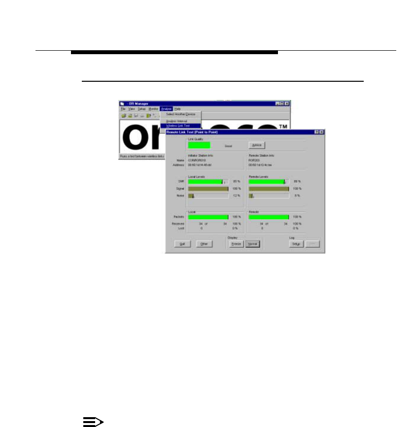
■Use the Wireless Link Test option of the OR Manager as described in the
"ORiNOCO OR Manager - User’s Guide" to analyze the radio link quality.
The Wireless Link Test option will enable you to display the strength of the
ORiNOCO radio signal related to the noise that may be appear in the signal
path.
Looking at the Wireless Link Test screen, you can interactively optimize
antenna alignment if required, by making small modifications in the antenna
orientation.
■Alternatively, consult a professional Antenna Installation Service to optimize
the antenna alignment.
Omni-directional antennas are characterized by a wide radiation pattern.
Therefore alignment of this type of antennas is less critical than for directional
antennas.
Preparing for Installation
Overview of the Outdoor Installation
ORiNOCO Outdoor Antenna Installation Guide 2-13
Figure 2-4 OR Manager Wireless Link Test
Antenna Polarization
The standard mounting method for Lucent Technologies outdoor antennas is
designed for vertical polarization.
In some cases you might consider mounting the antenna for horizontal
polarization. For example to minimize the influence of cross-talk between
antennas when:
■You plan to mount multiple directional antennas to the same mast.
■Your wireless link “crosses” another radio beam from a neighboring
installation.
Mounting for horizontal polarization is only supported by the
Lucent Technologies 14 dBi Directional Antenna and 24 dBi Directional
Parabolic Grid Antenna.
NOTE:
For optimal wireless performance you must always verify that the
polarization on both ends of the wireless link is the same for both
antennas.
Consult the corresponding appendices for instructions on alternating the
antenna polarization.

Preparing for Installation
Overview of the Outdoor Installation
2-14 ORiNOCO Outdoor Antenna Installation Guide
Antenna Cable Routing
The antenna cable must be routed and fixed in such a way to clear the passage
area for installation technicians.
All connectors that are located outdoors, must have a weatherproof seal. You
are advised to seal connectors only after you have completed final radio tests.

Preparing for Installation
Before Climbing the Roof...
ORiNOCO Outdoor Antenna Installation Guide 2-15
Before Climbing the Roof...
Before you start installation check whether you have all hardware components
required to setup an outdoor antenna link. For each side of a wireless outdoor
antenna link you will need:
1. One Outdoor Router or Outdoor Router Client.
2. One ORiNOCO PC Card.
3. One ORiNOCO Cable Assembly (to connect item 2 to item 4).
4. One ORiNOCO Surge Arrester.
5. One Lucent Technologies low-loss antenna cable.
6. One ORiNOCO Outdoor Antenna
7. Weather-proofing electrical tape.
If any of the items is missing, or if there are signs of shipment damage, please
inform your supplier.


Contents
3
Determine Range & Clearance
Introduction 3-1
Determine the Outdoor Range 3-2
Determine the Maximum Range 3-3
■Type of Outdoor Antenna Equipment 3-3
■Data Speed of the Wireless Link 3-7
Determine the Cable Factor 3-7
Determine the Clearance Factor 3-8
Examples 3-13
Point-to-Point Links 3-13
■Calculate the Clearance effect on Range 3-13
■Calculate the Cable effect on Range 3-14
Point-to-MultiPoint Links 3-15


ORiNOCO Outdoor Antenna Installation Guide 3-1
Determine Range &
Clearance
Introduction
When you read about wireless outdoor products, you will often encounter the
terms “output power” of the radio and “gain” of the antenna equipment as
measures for the “strength” of the transmitted signal.
■Output Power of radio equipment is often subject to maximum limits as
defined by local radio regulations (see Appendix G “Certified Outdoor
Solutions”). Consequently Output Power is not by definition the way to
enhance wireless performance.
■High gain antennas are larger in size than low gain antennas, and are
characterized by a narrow “focus” of the radio beam. These two
characteristics make it more difficult to aim the antennas, and/or adjust
antenna alignment to optimize the performance of the wireless point-to-point
link.
The Lucent Technologies outdoor solution is based upon the following
principles:
■An output power and antenna gain that comply with the maximum limits as
defined by local governing bodies concerning radio transmissions.
■Enhanced radio sensitivity for optimal receive quality of ORiNOCO radio
signals transmitted by remote antennas.
Determine Range & Clearance
Determine the Outdoor Range
3-2 ORiNOCO Outdoor Antenna Installation Guide
Determine the Outdoor Range
The range of your outdoor antenna installation is closely related to a number of
different factors. To allow you to determine the range of the ORiNOCO
Outdoor Router antenna system in your situation, we have defined the formula
listed below:
Range = Maximum Range x Cable Factor x Clearance Factor
■Maximum Range identifies the theoretical maximum that could be achieved
under optimal circumstances using the available ORiNOCO Outdoor
products according to their specs and in compliance with local radio
regulations.
This value can be read from Table 3-1 or Table 3-2, according to the country
where the antenna system will be installed.
■Cable Factor identifies a corrective percentage value that compensates
additional cable loss related to the type of cables applied at both ends of the
wireless link. The Cable Factor value can be read from Table 3-3 on
page 3-7.
■Clearance Factor identifies a corrective percentage value that should be
applied in case the signal path of your wireless link does not provide the
minimum clearance listed in the Maximum Range table. The Clearance
Factor can be read from Figure 3-2 on page 3-11.
An example on how to use this formula is described in the “Examples” on
page 3-13.
!CAUTION:
This formula should only be used as a rule of thumb to asses the
possible range that could be achieved in your situation, and/or to select
the type and height of the antenna installations. Always perform on-site
measurements to validate the results from the range calculation. To
perform such measurements you can use the OR Manager Wireless
Link test option as described in the "ORiNOCO OR Manager - User’s
Guide".
Determine Range & Clearance
Determine the Outdoor Range
ORiNOCO Outdoor Antenna Installation Guide 3-3
Determine the Maximum Range
The maximum range of your ORiNOCO Outdoor Router antenna system is
based on the:
■Type of Outdoor Antenna Equipment (page 3-3)
■Data Speed of the Wireless Link (page 3-7)
■Clearance of the Signal Path (see “Determine the Clearance Factor” on
page 3-8).
NOTE:
The values listed in this section are based upon calculations that
assume “optimal radio conditions”.
They do not represent a guarantee that the same maximum distance
can be achieved at your location. Different performance figures may
result from:
■Incorrect alignment of antennas (see “Antenna Alignment” on
page 2-12).
■Polarization mismatch of the antennas.
■Sources of interference or unexpected reflections in the signal path
that affect the communications quality (see “Antenna Placement”
on page 2-8).
■Severe weather conditions such as heavy rain or snow fall, or
strong winds.
■Seasonal influences such as leaves on trees, or icing on the
antennas.
Type of Outdoor Antenna Equipment
As described in the previous chapters, Lucent Technologies offers different
types of outdoor antennas, and cable lengths to design your ORiNOCO
Outdoor Router outdoor antenna installation.
■The directional antennas provide maximum range, but due to their narrow
signal beam width, these antennas require precise antenna alignment to
achieve optimal performance. The higher the antenna gain the more precise
the alignment should be.
Directional antennas are typically used to connect:
—Two Remote Outdoor Routers in a Point-to-Point link.
—One Remote Outdoor Router (satellite) to one Central Outdoor Router
(base) in a Point-to-Multipoint link.

Determine Range & Clearance
Determine the Outdoor Range
3-4 ORiNOCO Outdoor Antenna Installation Guide
■The omni-directional antennas, have by nature an omni directional azimuth
pattern which makes these antennas easy to install. There is also a gain
beam width relation for omni-antennas: the higher the gain of the omni-
antenna the narrower the vertical beam width. In a hilly terrain a 7dBi omni
antenna can/will be a better solution then the 10 dBi omni-antenna.
■The 12 dBi wide-angle antenna is a good solution for the Central Outdoor
Router (base) antenna in hilly terrain. It combines a wide opening angle with
relative high gain. The mounting brackets allow tilting of the antenna.
For beamwidth and gain characteristics of the various antennas, please
consult the appendices of this document that describe each antenna in more
detail.
The length of the antenna cable also has an impact on the maximum range that
can be achieved with the antenna combination (see “Determine the Cable
Factor” on page 3-7).
Subject to local radio regulations that in a number of countries limit the
maximum output power, Lucent Technologies offers different outdoor antenna
products in the various countries over the world. Therefore you will need to
consult the table that matches the radio regulations as apply in your country:
■Table 3-1 on page 3-5, for the USA and Canada and any other country that
adheres to the radio regulations as defined by the US Federal
Communications Commission (FCC).
■Table 3-2 on page 3-6, for all European countries, Japan, and any other
country that adheres to the radio regulations as defined by the European
Telecommunications Standards Institute (ETSI) and MPT.
Determine Range & Clearance
Determine the Outdoor Range
3-5 ORiNOCO Outdoor Antenna Installation Guide
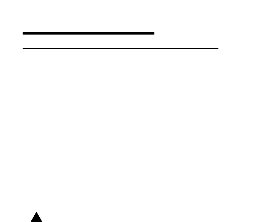
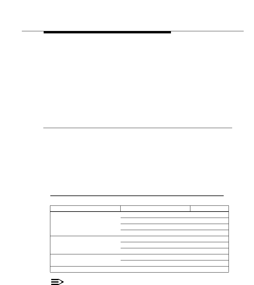
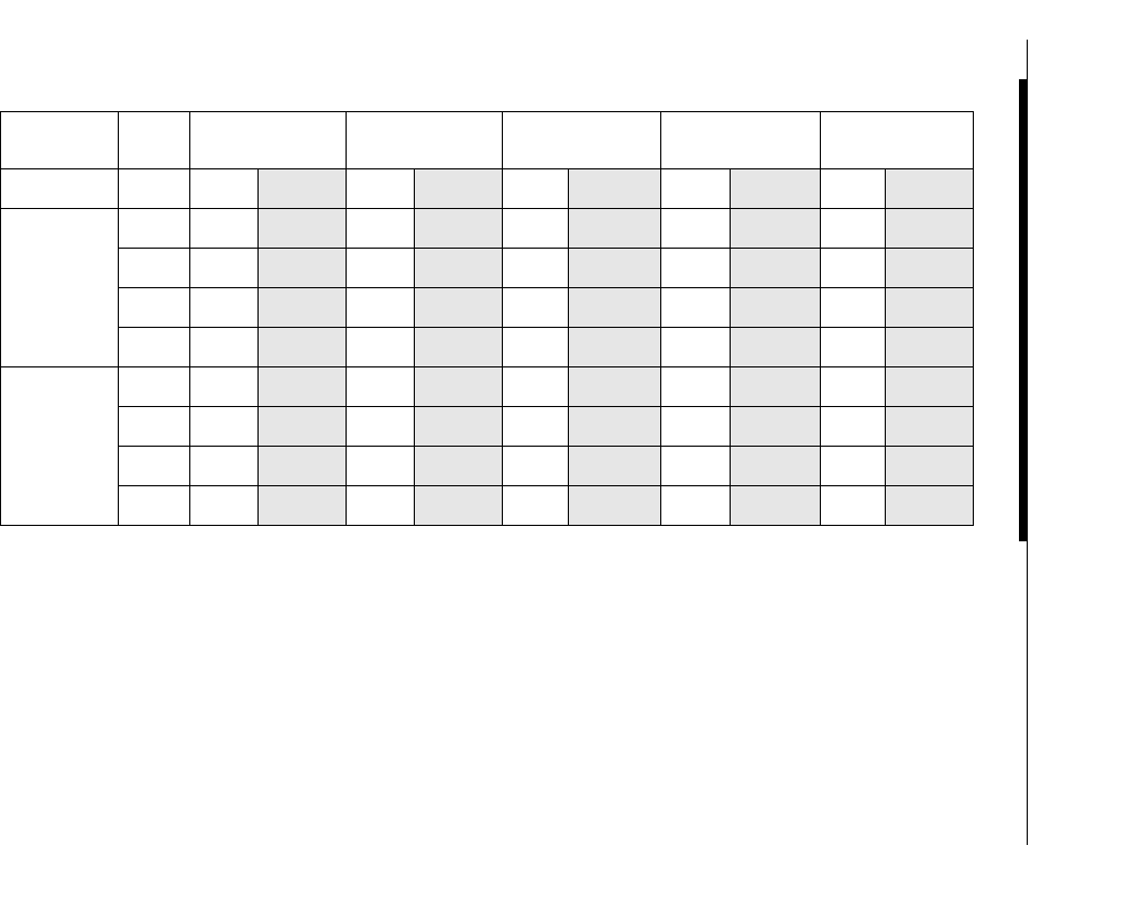
Table 3-1 Maximum Outdoor Range for FCC Products
All values in Table 3-1 are based on the use of the Standard black-colored ORiNOCO PC Card, and 6m (20 ft.) cables with a diameter of
10 mm. (0.4 in.) on both ends of the antenna link.
Antennas 24 dBi Directional
Parabolic Grid
Antenna1
1 The maximum ranges for the 24 dBi Grid antennas are calculated values. Maximum Ranges were only tested up to 110 km.
14 dBi Directional
Antenna 12 dBi Directional
Wide Angle Antenna 10 dBi Omni-
Directional Base
Station Antenna
7 dBi Omni-
Directional Base
Station Antenna
Speed Range Clearance Range Clearance Range Clearance Range Clearance Range Clearance
24 dBi
Directional
Parabolic
Grid
Antenna
1 Mb/s 240 km
149mi
1200 m
4000 ft.
74 km
46mi
150 m
490 ft.
60 km
37mi
101 m
331 ft.
48 km
30mi
70 m
230 ft.
34 km
21mile
45 m
148 ft.
2 Mb/s 170 km
105mi
610 m
2000 ft.
54 km
33mi
85 m
280 ft.
42 km
26mi
61 m
200 ft.
34 km
21mi
45 m
148 ft.
24 km
15mile
30 m
98 ft.
5.5 Mb/s 120 km
74mi
320 m
1050 ft.
38 km
23mi
50 m
164 ft.
30 km
18mi
39 m
128 ft.
24 km
15mi
30 m
98 ft.
17 km
10mile
20 m
66 ft.
11 Mb/s 85 km
52mi
180 m
590 ft.
27 km
16mi
35 m
115 ft.
21 km
13mi
27 m
89 ft.
17 km
10mi
21 m
69 ft.
12 km
7.5mile
16 m
52 ft.
14 dBi
Directional
Antenna
1 Mb/s 74 km
46mi
150 m
490 ft.
24 km
15mi
30 m
98 ft.
19 km
12mi
24 m
79 ft.
15 km
9.3mi
20 m
66 ft.
11 km
6.8mile
15 m
49 ft.
2 Mb/s 54 km
33mi
85 m
280 ft.
17 km
10mi
21 m
69 ft.
13 km
8.0mi
18 m
59 ft.
11 km
6.8mi
15 m
49 ft.
7.5 km
4.7mile
12 m
39 ft.
5.5 Mb/s 38 km
23mi
50 m
164 ft.
12 km
7.5mi
16 m
52 ft.
9.5 km
5.9mi
14 m
46 ft.
7.6 km
4.7mi
12 m
39 ft.
5.5 km
3.4mile
10 m
33 ft.
11 Mb/s 27 km
16mi
35 m
115 ft.
8.5 km
5.3mi
13 m
43 ft.
6.7 km
4.2mi
11 m
36 ft.
5.5 km
3.4mi
10 m
33 ft.
4.0 km
2.5mile
8 m
26 ft.
Determine Range & Clearance
Determine the Outdoor Range
3-6 ORiNOCO Outdoor Antenna Installation Guide
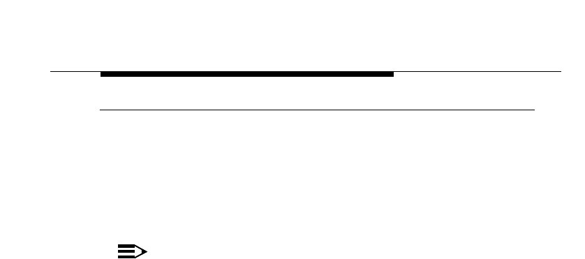
Table 3-2 Maximum Range for ETSI/FR/JP Products
NOTE:
All values listed in Table 3-2 are based on the correct use of the Red-colored Fixed Wireless PC Card and
cables as indicated in the corresponding footnote(s). Using different cards might violate ETSI radio
regulations (see also “Selecting the Right Card & Cables” on page G-3)
Antennas 14 dBi Directional
Antenna1
1 In combination with Red-colored Fixed Wireless PC Card and a 6 m (20 ft.) cable with diameter of 5 mm (0.2 in.)
12 dBi Directional
Wide Angle
Antenna2
2 In combination with Red-colored Fixed Wireless PC Card and a 6 m (20 ft.) cable with diameter of 10 mm (0.4 in.)
10 dBi Omni-
Directional Base
Station Antenna2
7 dBi Omni-
Directional Base
Station Antenna2
Data Speed Range Clearance Range Clearance Range Clearance Range Clearance
14 dBi Directional Antenna11 Mb/s 7 km
4.3mi
11 m
36 ft.
6.9 km
4.3mi
11 m
36 ft.
5.5 km
3.4mi
9.5 m
31 ft.
4.0 km
2.5mi
8 m
26 ft.
2 Mb/s 5 km
3.1mi
9 m
30 ft.
4.9 km
3.0mi
9 m
30 ft.
4.0 km
2.5mi
8 m
26 ft.
2.7km
1.7mi
6.6 m
22 ft.
5.5 Mb/s 3.5 km
2.2mi
7.5 m
25 ft.
3.5 km
2.2mi
7.5 m
25 ft.
2.7 km
1.7mi
6 m
20 ft.
1.9 km
1.2mi
5.5 m
18 ft.
11 Mb/s 2.5 km
1.6mi
6 m
20 ft.
2.5 km
1.6mi
6.5 m
22 ft.
2.0 km
1.2mi
5.5 m
18 ft.
1.4 km
0.9 mi
5.6 m
18 ft.
Determine Range & Clearance
Determine the Outdoor Range
ORiNOCO Outdoor Antenna Installation Guide 3-7
Data Speed of the Wireless Link
By default, the radio of ORiNOCO Outdoor Router products will transmit at the
highest available transmit rate.
As data transmissions at lower speeds can travel larger distances than
transmissions at the highest transmit rates, the ORiNOCO Outdoor Routers
allow you to choose a lower data rate to increase the maximum range. For
information about customizing the transmit rate of your Outdoor Router, please
consult the "ORiNOCO OR Manager - User’s Guide".
To help you to determine the appropriate tuning settings, we have listed the
range values that apply to the various transmit rates in Table 3-1 and Table 3-2.
Determine the Cable Factor
The range value calculations listed in Table 3-1 and Table 3-2 were based on
antenna installations where both antennas were connected to a 6m/20 ft. cable.
■If this is the case in your situation, the Cable Factor for your installation is
100%.
■If you are using different cables, you will need to determine the Cable Factor
from Table 3-3 below, to calculate the probable range for your ORiNOCO
Outdoor Router installation.
Table 3-3 Calculate the Cable Factor
NOTE:
When using Table 3-3 in countries that adhere to the ETSI regulations,
please note that the maximum ranges as listed in Table 3-2 do not
always use cable factor 100%.
This Location Remote Location Cable Factor
6m. (20 ft.)/10 mm (0.4 in.) 6m. (20 ft.)/10 mm (0.4 in.) 100%
6m. (20 ft.)/5 mm (0.2 in.) 81%
15m. (50 ft.) 81%
22m. (75 ft.) 67%
6m. (20 ft.)/5 mm (0.2 in.) 6m. (20 ft.)/5 mm (0.2 in.) 66%
15m. (50 ft.) 66%
22m. (75 ft.) 54%
15m. (50 ft.) 15m. (50 ft.) 66%
22m. (75 ft.) 54%
22m. (75 ft.) 22m. (75 ft.) 45%
Determine Range & Clearance
Determine the Outdoor Range
3-8 ORiNOCO Outdoor Antenna Installation Guide
This is due to local radio regulations and legislation that do not allow the
use of the 6 m. (20 ft.)/10 mm (0.4 in.) cables in ETSI countries, France
or Japan. See the example on Point-to-MultiPoint Links (page 3-15) for
more details.
!CAUTION:
The 6m (20 ft.) cables with a diameter of 5mm (0.2 in.) can be used with
all antenna types. The Cable Loss of these cables equals the value of
the 15m.(50ft.) cables. Use of the 6m (20 ft.) cables with a diameter of
10mm (0.4 in.) is subject to local radio regulations. Consult Appendix
G“Introduction” for information whether you are allowed to use the 6m/
10mm cable in your country in combination with the antenna of your
choice.
Determine the Clearance Factor
For optimal performance of your outdoor antenna link, it is important that the
signal path between the two ORiNOCO Outdoor Routers provides sufficient
clearance.
NOTE:
A wireless outdoor antenna link that lacks sufficient clearance will suffer
from poor performance, which is typically perceived as slow network
response times.
Although your ORiNOCO Outdoor Router equipment will automatically
retransmit every data frame that got lost due to an out-of-range situation
or frame collision, the larger the number of retransmissions attempts,
the lower the throughput efficiency of your wireless link.
This section will explain how to determine the clearance that applies in your
environment, and (if applicable) the effect of insufficient clearance on the range
of your outdoor antenna link.
In Chapter 2 “Preparing for Installation” we described the shape of the radio
beam being “bulged” in the middle, as pictured in Figure 3-1 on page 3-9.
Determine Range & Clearance
Determine the Outdoor Range
ORiNOCO Outdoor Antenna Installation Guide 3-9
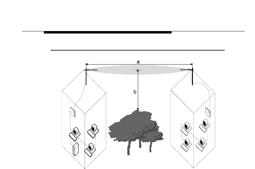
Figure 3-1 Fresnel Zone
If any significant part of this bulged zone is obstructed, a portion of the radio
energy will be lost, which may affect the performance of your wireless link in
terms of maximum range and/or transmit rate.
Looking at Figure 3-1 you will see two variables that determine the shape of the
radio beam, also referred to as Fresnel Zone:
a. The distance between the antennas
b. The clearance required for optimal performance, where clearance should be
interpreted as:
■Vertical clearance above the ground and the highest buildings or objects
in the signal path, and
■Horizontal clearance from neighboring buildings and objects in the
signal path.
For optimal range and throughput performance, you must ensure that your
antenna installation provides maximum clearance in both horizontal and vertical
direction.
The minimum clearance for the various antenna combinations and distances is
listed in the grey-shaded columns of Table 3-1 and Table 3-2, where clearance
should be interpreted as follows:

Determine Range & Clearance
Determine the Outdoor Range
3-10 ORiNOCO Outdoor Antenna Installation Guide
■In open areas without obstacles in the signal path, clearance is measured
as height above the surface of the earth.
For example, if the antenna is mounted on the roof, this height includes the
height of the building plus the height of the mast above the rooftop.
■In areas with obstacles in the signal path between the two antenna(s),
clearance should be measured as height above the highest obstacle(s) in
the signal path.
■In dense urban areas, the clearance should be measured as height above
the highest rooftop or any other obstacle(s) in the signal path between the
two antenna(s).
Looking at the minimum clearance requirements as identified in Table 3-1 and
Table 3-2, you may realize that local authorities, the proprietor of the premises,
or other reasons may not allow you to set up an antenna mast that will enable
you to meet the listed clearance requirement.
In such situations, you may not be able to achieve a full line-of-sight clearance.
At the same time however, you may not even need full clearance, since the
distance that your wireless outdoor installation needs to cover is less than the
listed maximum range.
To determine the effect of insufficient signal path clearance, you will need to
determine the Clearance Factor as described below, and calculate its effect on
the range for your antenna installation using the formula described in “Determine
the Outdoor Range” on page 3-2.
■If the clearance for your antenna installation is equal to, or better than the
minimum clearance requirement identified in Table 3-1 and Table 3-2, the
Clearance Factor for your installation is 100%.
■If your actual clearance is less than the minimum clearance identified in
Table 3-1 or Table 3-2, you will need use the diagram pictured in Figure 3-2
to determine the actual range that will apply in your situation.
Determine Range & Clearance
Determine the Outdoor Range
ORiNOCO Outdoor Antenna Installation Guide 3-11
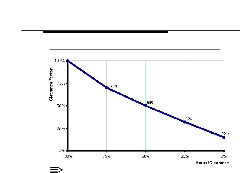
Figure 3-2 Clearance Factor Diagram
NOTE:
The Clearance Factor Diagram should be used as a rule-of-thumb for
estimating the probable range in case the clearance requirements are
not fully met.
In real life using FCC approved products, you will also find it almost
impossible to achieve the level of clearance for maximum range.
For your convenience we have also included Table 3-4 to provide an
example in conditions where the more typical clearance is 10 meters
(33 ft.)
Determine Range & Clearance
Determine the Outdoor Range
3-12 ORiNOCO Outdoor Antenna Installation Guide
Table 3-4 FCC Outdoor Range with 10 m (33 ft.) Clearance
Antennas 24 dBi Directional
Parabolic Grid
Antenna
14 dBi Directional
Antenna 12 dBi Directional
Wide Angle Antenna 10 dBi Omni-
Directional Base
Station Antenna
7 dBi Omni-
Directional Base
Station Antenna
Data
Speed Range Clearance Range Clearance Range Clearance Range Clearance Range Clearance
24 dBi
Directional
Parabolic Grid
Antenna
1 Mb/s 26.2 km
16.3 mi 10 m
33 ft. 19.0 km
11.8mi 10 m
33 ft. 17.3 km
10.7mi 10 m
33 ft. 15.8 km
9.8mi 10 m
33 ft. 14.1 km
8.8mi 10 m
33 ft.
2 Mb/s 24.5 km
15.2mi 10 m
33 ft. 16.9 km
10.5mi 10 m
33 ft. 15.4 km
9.6mi 10 m
33 ft. 14.1 km
8.8mi 10 m
33 ft. 12.0 km
7.5mi 10 m
33 ft.
5.5 Mb/s 21.8 km
13.5mi 10 m
33 ft. 14.4 km
8.9mi 10 m
33 ft. 13.1 km
8.1mi 10 m
33 ft. 12.0 km
7.5mi 10 m
33 ft. 10.2 km
6.3mi 10 m
33 ft.
11 Mb/s 19.4 km
12.0mi 10 m
33 ft. 12.8 km
8.0mi 10 m
33 ft. 11.2 km
7.0mi 10 m
33 ft. 10.2 km
6.3mi 10 m
33 ft. 8.7 km
5.4mi 10 m
33 ft.
14 dBi
Directional
Antenna
1 Mb/s 19.0 km
11.8mi 10 m
33 ft. 12.0 km
7.5mi 10 m
33 ft. 10.9 km
6.8mi 10 m
33 ft. 9.5 km
5.9mi 10 m
33 ft. 8.1 km
5.0mi 10 m
33 ft.
2 Mb/s 16.9 km
10.5mi 10 m
33 ft. 10.2 km
6.3mi 10 m
33 ft. 9.3 km
5.8mi 10 m
33 ft. 8.1 km
5.0mi 10 m
33 ft. 6.6 km
4.1mi 10 m
33 ft.
5.5 Mb/s 14.4 km
8.9mi 10 m
33 ft. 8.7 km
5.4mi 10 m
33 ft. 7.6 km
4.7mi 10 m
33 ft. 6.6 km
4.1mi 10 m
33 ft. 5.5 km
3.4 mi 10 m
33 ft.
11 Mb/s 12.8 km
8.0mi 10 m
33 ft. 7.1 km
4.4mi 10 m
33 ft. 6.1km
3.8mi 10 m
33 ft. 5.5 km
3.4 mi 10 m
33 ft. 4.0 km
2.5 mi 10 m
33 ft.
Determine Range & Clearance
Examples
ORiNOCO Outdoor Antenna Installation Guide 3-13
Examples
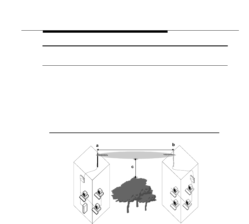
Point-to-Point Links
Suppose you are installing a wireless point-to-point link between two Remote
Outdoor Routers as pictured in Figure 3-3 below, where:
■Both sites have been equipped with a 24 dBi Directional Parabolic Grid
Antenna, connected via 6m.(20 ft.)/10 mm antenna cables.
■The distance between site a and b is 25 km. (15.3 mi.).
■The site is located in the US, which allows the use of FCC approved
equipment.
Figure 3-3 Calculating the Point-to-Point Range
Looking at Table 3-1 on page 3-5, we learn that a High Speed link between two
24 dBi Directional Grid Antennas may cover a maximum distance of 85 Km.(52
mi.), provided that the signal path clearance is 180 m. (590 ft.) or better.
Now let’s calculate the probable range for this example using the introduced
formula:
Range = Maximum Range x Cable Factor x Clearance Factor
Calculate the Clearance effect on Range
In the example pictured in Figure 3-3 on page 3-13, we see a set of trees in the
signal path. Let’s suppose the clearance (c) between these trees and the signal
path is only be 45 m (148 ft.).

Determine Range & Clearance
Examples
3-14 ORiNOCO Outdoor Antenna Installation Guide
1. Using a calculator we can easily determine that this 45 m (148 ft.) is about
25% of the required 180 m. (590 ft.) clearance for maximum range.
2. Looking at the “Clearance Factor Diagram” pictured in Figure 3-2 on
page 3-11 we can see that 25% actual clearance, equals a Clearance Factor
of 32%.
3. If we apply this Clearance Factor to the range calculation formula, your
probable range would become:
Range= 85 Km (52 mi.) x 32% x 100% = 27.2 Km (16.6 mi.)
This might satisfy your requirements for High Speed data transmissions between
the two ORiNOCO Office Routers. However the “safety margin” looks pretty
tight.
If we would base the calculation on transmissions at Medium speed, your range
calculation would look as follows:
1. Looking at Table 3-1 on page 3-5, we learn that a Medium Speed link
between two 24 dBi Directional Parabolic Grid Antennas may cover a
maximum distance of 120 Km.(74 mi.), provided that the signal path
clearance is 320 m. (1050 ft.).
2. As mentioned above however, our actual clearance is only
45 m (148 ft.); 14% of the required 320 m. (1050 ft.).
Range= 120 Km (74 mi.) x 25% x 100% = 30 Km (18.6 mi.)
This result indicates that you can safely set the transmit rate of your ORiNOCO
Outdoor Router to Medium Speed for reliable wireless communications.
Optionally you may wish to run the Wireless Link Test option of your
OR Manager program to determine whether the High Speed option might
provide reliable wireless connections as well.
Calculate the Cable effect on Range
We presumed that at both sites the antenna were connected via 6m.(20 ft.)
cables with a diameter of 10 mm (0.4 in.).
If we would replace this cable at building b, with a longer 22 m. (75 ft.) cable, we
would need to look at the Cable Factor effect of this longer cable.
1. Table 3-3 on page 3-7 tells us that this new cabling combination would result
in a Cable Factor of 67%.
2. If we apply this Cable Factor to the range calculation formula again, your
probable range would become:
Range= 120 Km.(74 mi.) x 25% x 67% = 20.1 Km (12.5 mi.)

Determine Range & Clearance
Examples
ORiNOCO Outdoor Antenna Installation Guide 3-15
This result indicates that the effect of this cable will most likely prevent your
wireless link from operating at both High and Medium Speed. In such situations
you are advised to:
■Relocate the Outdoor Router hardware to a location that allows you to use a
shorter cable length.
■Increase the height of the antenna on the mast and/or install taller antenna
masts to increase the signal path clearance.
■Trade-off data speed versus range, and recalculate the ranges that could be
achieved at lower Transmit Rates.
Alternatively, you may decide to perform on-site diagnostic measurements to
validate the results of this calculation. Please consult the "ORiNOCO OR
Manager - User’s Guide" for information about using the Wireless Link Test
feature to perform on-site diagnostic measurements.
The "ORiNOCO OR Manager - User’s Guide" is available in electronic format on
the ORiNOCO Outdoor Router CD-ROM.
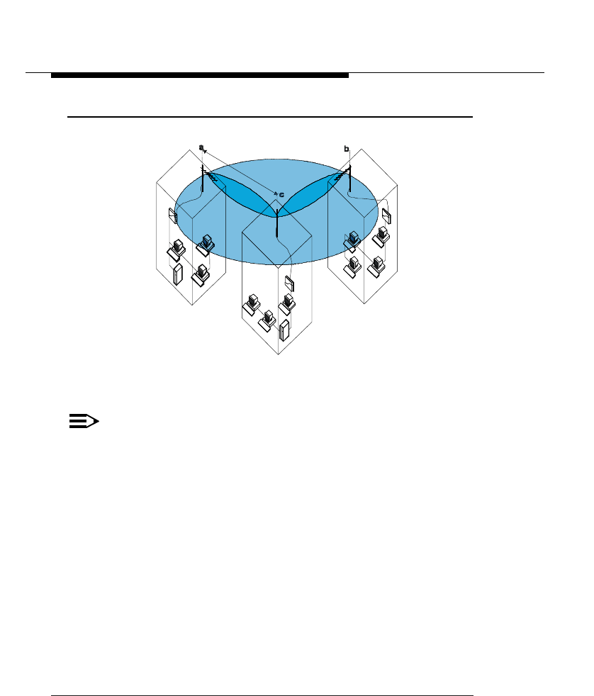
Point-to-MultiPoint Links
Suppose you are installing a wireless Point-to-Multipoint link between one
ORiNOCO Central Outdoor Router and two Remote Outdoor Routers as
pictured in Figure 3-4 below, where:
■The Central Outdoor Router in building c is connected to a 7 dBi Omni-
Directional Base Station Antenna, and
■The two remote sites a and b have been equipped with a 14 dBi Directional
Antenna.
■All sites have been connected via 15m.(50 ft.) antenna cables.
■The site is located in the Europe, which requires you to use ETSI approved
equipment1.
1 In France you may only use equipment based on the FR channel-set.
Determine Range & Clearance
Examples
3-16 ORiNOCO Outdoor Antenna Installation Guide
Figure 3-4 Calculating the Point-to-Multipoint Range
For this type of outdoor antenna installation you will need to determine the range
for each link individually, i.e. the range from the building c to building a, and from
the building c to building b.
NOTE:
In this example we will only demonstrate the calculation for the link
between building a and c. However as different clearance factors may
apply for each of these links, you are advised to calculate the actual
range for each link individually when designing a “real” outdoor antenna
link.
For the purpose of this example we presume that:
■The antenna installation will be installed in a dense urban area, where the
distance between building a and building c is 0.5 Km.(0.3 mi.).
■The actual clearance is 3m. (9.9ft.), being the height of the antennas on the
mast2.
Now let’s calculate the probable range for this example using the introduced
formula:
Range = Maximum Range x Cable Factor x Clearance Factor
2 According to the information about dense urban areas described in “Determine the Clearance
Factor” on page 3-8, we use the height of the antennas above the roof-tops of both buildings to
determine the level of actual clearance.

Determine Range & Clearance
Examples
ORiNOCO Outdoor Antenna Installation Guide 3-17
1. Looking at Table 3-2 on page 3-6, we learn that a High Speed link between a
7 dBi Omni-Directional Base Station Antenna and a 14 dBi Directional
Antenna may cover a maximum distance of 1.4 Km. (0.9 mi.), provided that
the signal path clearance is 5.6m. (18 ft.) or better.
2. Using a calculator we can easily determine that the actual clearance of 3m.
(9.9ft.) is about 75% of the required 5.6m. (18 ft.) which equals a Clearance
Factor of 70% (see Figure 3-2 on page 3-11).
3. The maximum range calculation in Table 3-2 on page 3-6 was based on the
use of:
■a 6m. (20 ft.) cables with a diameter of 5mm (0.2 in.). for the site with the
14 dBi Directional Antenna, and
■a 6m. (20 ft.) cables with a diameter of 10mm. (0.4 in.) for the 7 dBi
Omni-Directional Base Station Antenna.
In other words, the Cable Factor for the maximum range calculation,
already represents a value of 81% (see Table 3-3 on page 3-7).
However since the site as pictured in Figure 3-4 on page 3-16 site is actually
using two 15m (50 ft.) cables, Table 3-3 identifies the Cable Factor as being
66%.
You actual Cable Factor will be 66% Cable Factor divided by the maximum
range cable factor: (66%/81%)= 81%.
4. If we import all this information into the range calculation formula, your
probable range for High Speed transmissions would become:
Range= 1.4 Km. (0.9 mi.) x 70% x (66%/81%) = 0.8 Km (0.5 mi.)
For campus type environments, this range will probably be sufficient to connect
multiple buildings. However if you would need to cover a larger distance, you
can either:
■Relocate the Outdoor Router hardware to a location that allows you to use a
shorter cable length.
■Increase the height of the antenna on the mast and/or install taller antenna
masts to increase the signal path clearance.
■Trade-off data speed versus range, and recalculate the ranges that could be
achieved at lower Transmit Rates.
Alternatively, you may decide to perform on-site diagnostic measurements to
validate the results of this calculation. Please consult the "ORiNOCO OR
Manager - User’s Guide" for information about using the Wireless Link Test
feature to perform on-site diagnostic measurements.
This guide is available in electronic format on the ORiNOCO Outdoor Router
CD-ROM, or can be downloaded from the ORiNOCO website at: http://
www.lucent.com/orinoco.


ORiNOCO Outdoor Antenna Installation Guide 4-1
Installing the Antenna
Planning Antenna Installation
Carefully plan the day for your outdoor antenna installation. Do not install the
antenna in wet or windy conditions, during a thunderstorm or when the area
where the equipment will be installed is covered with ice or snow.
The grounding system for the antenna mast, Outdoor Router hardware and
ORiNOCO Surge Arrester should be installed before the cable from the antenna
is connected to the lightning arrestor. This will protect your ORiNOCO Outdoor
System in case lightning should strike the antenna during installation.
Familiarize yourself with the antenna and the antenna specific mounting
instructions prior to climbing any roof or ladder. Installing and testing all
equipment before beginning the actual rooftop installation will help you to
determine whether all required equipment and items are available and are
functioning properly.
To verify the equipment prior to installation, you may need to skip this chapter
and first proceed with the guidelines as described in the "ORiNOCO OR
Manager - User’s Guide".
The "ORiNOCO OR Manager - User’s Guide" is shipped with the
Outdoor Router device, and can be downloaded from the ORiNOCO website at:
http://www.lucent.com/orinoco.
Safety Precautions
Please read this section carefully before beginning the installation. All
requirements listed below should be satisfied prior to starting installation of your
ORiNOCO outdoor antennas.
Installing the Antenna
Planning Antenna Installation
4-2 ORiNOCO Outdoor Antenna Installation Guide
!DANGER:
The ORiNOCO Outdoor Router outdoor antennas are intended for
mounting on a roof, or the side of a building. Installation shall not be
attempted by someone who is not trained or experienced in this type of
work.The antenna has to be installed by a suitably trained professional
installation technician or a qualified antenna installation service. The site
pre-requisites have to be checked by a person familiar with the national
electrical code, and other regulations governing this type of installation.
Outdoor antennas and antenna cables are electrical conductors.
Transients or electrostatic discharges that may occur at the antenna (for
example a lightning strike during thunderstorms) may damage your
electronic equipment and cause personal injury or death to persons
touching the exposed metal connectors of the antenna cable.
When installing, disconnecting or replacing one of the cabling
components, you must ensure at all times that each exposed metal
connectors of the antenna cabling system will be grounded locally
during the work.
Do not install this antenna where there is any possibility of contact with
high-voltage arc-over from power cables or service drops to buildings.
The antenna, supporting mast and/or tower must not be close to any
power lines during installation, removal or in the event of part of the
system should accidentally fail. Apply a “Danger” label to a plainly
visible area of the antenna support structure.
1. Do not climb rooftops in wet or windy conditions, during a
thunderstorm or when the area where the equipment will be
installed is covered with ice or snow.
2. Do not touch antennas, surge arresters and/or antenna cables
during a thunderstorm.
3. The location where you will install the antenna(s) must be at a safe
distance from power lines or telephone lines. The safe distance
should be at least twice the height of the antenna mast plus the
height of the antenna.
4. Antennas shall be mounted in such a manner to minimize the
potential for human contact during normal operation. In order to
avoid the possibility of exceeding the FCC radio frequency
exposure limits, human proximity to the antenna shall not be less
than 20cm (8 inches) during normal operation.

Installing the Antenna
Planning Antenna Installation
ORiNOCO Outdoor Antenna Installation Guide 4-3
5. The low-loss antenna cable that will connect the antenna with the
lightning arrestor must be at least 1m (3 ft.) away from any high
voltage or high current cable.
6. Check whether the antenna mast and its guy wires or wall bracket
are positioned correctly and secured properly to the roof or wall(s).
7. Check whether the grounding system for the antenna mast, the
Outdoor Router hardware and ORiNOCO Surge Arrester have
been installed. The grounding system must comply with the
requirements as described in “Grounding System” on page 2-12.
Always consult a qualified electrician if you are in doubt as to
whether the antenna mast, the ORiNOCO Surge Arrester and
Outdoor Router hardware are properly grounded.
8. The antenna cable between the antenna and the lightning arrestor
must be grounded at all times. If the cable is disconnected at one
end for some reason (for example, to replace the lightning arrestor)
then you must ensure that the exposed metal connector of the
cable is grounded locally during the work.
Installation Overview
The installation process can be summarized in the following 10 steps.
1. Verify that the support structure for the antenna has been connected to the
grounding system. If this is not the case you should do so now.
2. Connect the exposed metal connectors of the low-loss antenna cable to the
grounding system.
3. Mount the antenna to the support structure, following the guidelines as
described for your antenna in Appendices B through F.
4. Connect the antenna cable to the antenna
5. Route the antenna cable to the ORiNOCO Surge Arrester that has been
installed indoors.
6. Connect the antenna cable to the Surge Arrester.
7. Connect the Cable Assembly to the Surge Arrester.
8. Connect the opposite end of the Cable Assembly to the connector in the
extended part of the ORiNOCO card that protrudes from the host device.
Installing the Antenna
Planning Antenna Installation
4-4 ORiNOCO Outdoor Antenna Installation Guide
9. Run the Wireless Link Test diagnostics of the OR Manager program to aim
the antenna and verify optimal placement.
10. Once the antenna is correctly positioned, and you have verified the
installation works properly, secure all cables and use weather-proofing tape
to seal all outdoor connectors.
!WARNING:
When you need to remove or relocate the antenna, follow the “Safety
Precautions” on page 4-1, and follow the steps listed above in exactly
the reverse order.

Installing the Antenna
Mounting the Antenna
ORiNOCO Outdoor Antenna Installation Guide 4-5
Mounting the Antenna
Lucent Technologies offers multiple antennas to setup a wireless link.
As the mounting procedures for the various antennas may differ from one
another, please consult the corresponding Appendix for the antenna type that
you plan to install:
■Appendix B “14 dBi Directional Antenna”
■Appendix C “7 dBi Omni-Directional Base Station Antenna”
■Appendix D “10 dBi Omni-Directional Base Station Antenna”
■Appendix E “12 dBi Directional Wide Angle Antenna”
■Appendix F “24 dBi Directional Parabolic Grid Antenna”
When mounting multiple antennas on a single mast, use the following methods
to minimize the influence of cross-talk interference between the antennas:
■Place your antennas as far apart as you can.
■Alternate the mounting of directional antennas for vertical and horizontal
polarization.
Consult the mounting instructions for your antenna as described in the
appendices listed above for options and instructions to mount the antennas
for different polarization.
Installing the Antenna
Connecting the Antenna Cable
4-6 ORiNOCO Outdoor Antenna Installation Guide
Connecting the Antenna Cable
Once the antenna is properly installed, you can connect the antenna to the
ORiNOCO Wireless System via the ORiNOCO Surge Arrester.
1. First connect the antenna cable to the antenna
2. Secure the antenna cable to the mast such that the cable connectors do not
support the full weight of the cable.
3. Connect the opposite end of the antenna cable to the ORiNOCO Surge
Arrester.
NOTE:
To avoid damage to the antenna cable and connectors, refrain from
using appliances to tighten the cable connectors
4. Prior to securing the cable along its complete length, run the Wireless Link
Test diagnostics of the OR Manager program to analyze wireless
performance and optimal placement of the outdoor antenna (see Figure 2-4
on page 2-13). How to use this program is described in the "ORiNOCO OR
Manager - User’s Guide" that was shipped with the Outdoor Router
hardware, and/or can be downloaded from the
ORiNOCO website at: http://www.lucent.com/orinoco.
5. If required, adjust the direction of the antenna.
6. Once the installation has been fully tested, tighten the nuts of the antenna to
‘lock’ the antenna into its position.
!CAUTION:
Avoid overtightening of the connectors, and nuts and screws used to
mount the antenna, to prevent damage to your ORiNOCO
Outdoor Router hardware.
7. Secure the cable along its complete length using cable ties or electrical tape
to properly strain relieve the antenna connector.
No part of the cable should be allowed to hang free. This is especially
important for those parts that are routed outside the building.
8. Proceed as described below to weather-proof all outdoor coax connectors.

Installing the Antenna
Connecting the Antenna Cable
ORiNOCO Outdoor Antenna Installation Guide 4-7
Sealing the Cable Connectors
Most problems associated with wireless outdoor installations are related to
degrading performance due to the effects of corrosion of the antenna cable and
cable connectors. To avoid this type of problems, you must always seal the
cable connectors that are located outdoors using the weather proofing tape
provided.
You are advised to seal the connectors only after you have verified optimal
alignment of the antennas using the Wireless Link Test as described in the
"ORiNOCO OR Manager - User’s Guide". Doing so will enable you to adjust
antenna placement and cable routing without removing the tape.
1. Prepare the cable and connectors so that they are free from dust, dirt and
grease.
2. Attach the tip of the weather proofing tape to the cable just above the
connector.
3. Holding the tape in its position, now stretch the tape and wind it half-lapped
around the cable and connectors to form a void-free joint.
The degree of stretch may vary in different sections of the joint, as long as
the overlaps accomplish a void-free application.
To protect the weather-proofing stretch tape from the effects of Ultra-Violet (UV)
radiation (for example from direct sun-light), you should protect the joint with two
half-lapped layers of any vinyl plastic electrical tape. Alternatively, you can apply
silicone sealer to protect the weather-proofing tape from sunlight, rain and other
weather conditions.

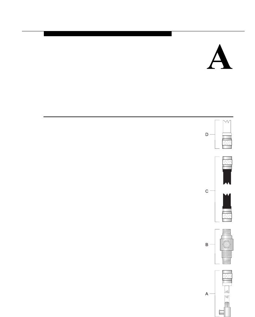
ORiNOCO Outdoor Antenna Installation Guide A-1
The Antenna Cabling
System
The Outdoor Cabling Components

The Antenna Cabling System
The Outdoor Cabling Components
A-2 ORiNOCO Outdoor Antenna Installation Guide
To connect your Outdoor Router hardware to an outdoor antenna installation you
will need the following cabling components as pictured on the right side of this
page:
a. The ORiNOCO Cable Assembly
b. The ORiNOCO Surge Arrester
c. A Low-Loss Antenna Cable
d. One of the outdoor antennas described in Appendices B through F.
When purchasing new ORiNOCO Outdoor Router products, each of the
components listed above will be equipped with Standard N-Type connectors.
When ordering separate components, for example as a spare part or
replacement to previously purchased Lucent ORiNOCO outdoor antenna
equipment carefully read the note on the following page to ensure that you
order components with an N-Type connector that matches the other parts of
your Outdoor Antenna Cabling System.
Selecting the Correct Connector-Type
All cabling components of the ORiNOCO Outdoor Antenna system come with
Standard-N type connectors as pictured in Table A-1 below.
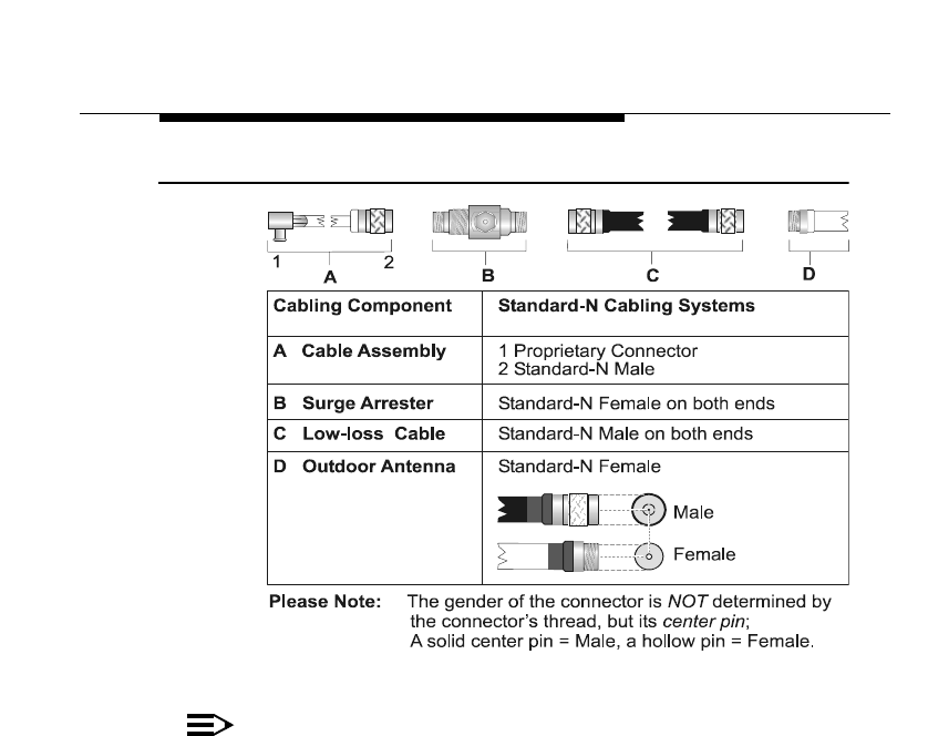
The Antenna Cabling System
The Outdoor Cabling Components
ORiNOCO Outdoor Antenna Installation Guide A-3
Table A-1 Standard N-Type Connector Diagram
NOTE:
Previously marketed ORiNOCO outdoor antenna systems in FCC
regulated countries (e.g. USA & Canada) were shipped with a different
cabling system, identified by Reverse Polarity-N connectors (pictured in
Table A-2 on page A-4).
If you are looking for replacement parts, or wish to extend a previously
installed Reverse Polarity-N cabling system, please consult your
Authorized ORiNOCO Reseller. You can use Table A-2 to:
■Determine the type of cabling system currently installed.
■Determine what type of spare part or converter you will need if you
intend to upgrade or replace a previously installed outdoor cabling
system.
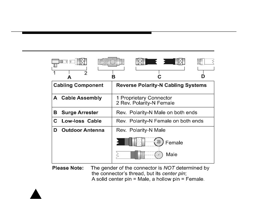
The Antenna Cabling System
The Outdoor Cabling Components
A-4 ORiNOCO Outdoor Antenna Installation Guide
Table A-2 Reverse Polarity-N Cabling Diagram
!DANGER:
Outdoor antennas and antenna cables are electrical conductors.
Transients or electrostatic discharges that may occur at the antenna (for
example a lightning strike during thunderstorms) may damage your
electronic equipment and cause personal injury or death to persons
touching the exposed metal connectors of the antenna cable.
To avoid damage and personal injury, the entire antenna cabling system
must be grounded at all times.
When installing, disconnecting or replacing one of the cabling
components, you must ensure at all times that each exposed metal
connectors of the antenna cabling system will be grounded locally
during the work.
For example when mounting or replacing the ORiNOCO Surge Arrester:
1. First connect each of the connectors of the low-loss antenna cables to the
grounding system.
2. Next connect the cable connector of the ORiNOCO Cable Assembly to the
grounding system.

The Antenna Cabling System
The Outdoor Cabling Components
ORiNOCO Outdoor Antenna Installation Guide A-5
3. Finally connect the ORiNOCO Surge Arrester to the grounding system.
Before you proceed, verify that each of the items is properly grounded, and that
the ground will not interrupted when disconnecting one of the antenna system
components.
Check with a qualified electrician if you are in doubt as to whether the surge
arrester, and cable connectors are properly grounded.
Only after you have verified that each of the items is properly grounded, replace
the surge arrester and re-connect the cables in exactly the reverse order of the
previous steps.
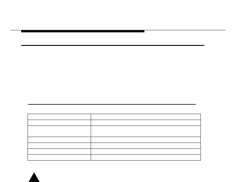
The Antenna Cabling System
ORiNOCO Cable Assembly
A-6 ORiNOCO Outdoor Antenna Installation Guide
ORiNOCO Cable Assembly
The ORiNOCO Cable Assembly is the Lucent Technologies proprietary cable to
connect ORiNOCO PC Cards to an outdoor antenna system.
On the end that is connected to the ORiNOCO card, the cable assembly has the
Lucent Technologies proprietary connector.
The N-Type connector at the opposite end will match the polarity of the N-
connectors of the other outdoor antenna cabling system components.
Table A-3 Specifications Cable Assembly
!CAUTION:
The Lucent proprietary connector that fits into the ORiNOCO PC Card
has been designed for “fixed installations” only, allowing for occasionally
disconnecting and reconnecting the outdoor antenna cabling system
when needed. Repeatedly (dis)connecting the Cable Assembly, will
wear out the connectors and void Warranty of the Cable Assembly
product.
Mechanical
Length 50 cm (19.5 in.)
Connectors1
1 See also “Selecting the Correct Connector-Type” on page A-2
■Proprietary ORiNOCO PC Card Connector
■Standard-N (Male)
Operating Temperature - 40°C to +85°C
Electrical
Frequency Range 800-2500 MHz
Insertion Loss 0.9 dB
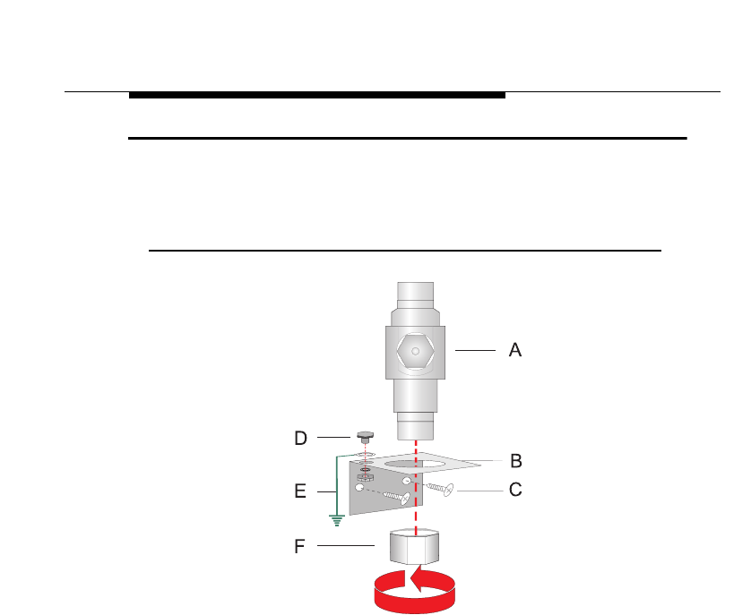
The Antenna Cabling System
ORiNOCO Surge Arrester
ORiNOCO Outdoor Antenna Installation Guide A-7
ORiNOCO Surge Arrester
The ”ORiNOCO Surge Arrester” (sometimes also referred to as “Lightning
Protector”) can protect your sensitive ORiNOCO equipment from high-voltage
surges caused by discharge and transients at the antennas.
Figure A-1 Mounting the ORiNOCO Surge Arrester
To mount the ORiNOCO Surge Arrester:
1. Determine a suitable location for the bracket (item B) as described in
Chapter 2 “Preparing for Installation”.
2. Use the screws (item C) to attach the bracket the wall.
3. Apply a ring-terminal to the ground wire, and use the bolt, lock-washer and
nut (item D) to connect the ground-wire (item E) to the mounting bracket.
The ring-terminal and ground wire are not included, but must be installed by
a certified electrician that is familiar with national electricity & safety codes,
according the instructions described under “Grounding System” on
page 2-12
4. Next insert the ORiNOCO Surge Arrester (item A” into the bracket as
pictured in Figure A-1.
5. Use the hex-nut (item F) to secure the ORiNOCO Surge Arrester in its
position, and ensure that the Protector is properly connected to the
grounding system.
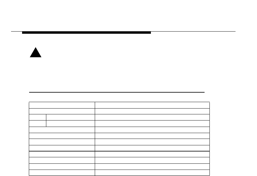
The Antenna Cabling System
ORiNOCO Surge Arrester
A-8 ORiNOCO Outdoor Antenna Installation Guide
!WARNING:
To avoid damage to electronic equipment and your ORiNOCO
equipment always apply the “ORiNOCO Surge Arrester” between the
outdoor antenna installation and the Outdoor Router hardware or other
computing device that is connected to the outdoor antenna(s).
Table A-4 Specifications Surge Arrester
Mechanical
Size
Height 69 mm (2.7 in.)
Diameter 26 mm (1 in.)
Weight 133 g (4.7 oz.)
Connectors1
1 See also “Selecting the Correct Connector-Type” on page A-2
Standard-N (Female on both ends)
Operating Temperature - 40°C to +85°C
Electrical
Frequency Range 800-2500 MHz
Insertion Loss 0.2 dB
Surge Current 2000 Amp
Nominal Impedance 50 Ohms
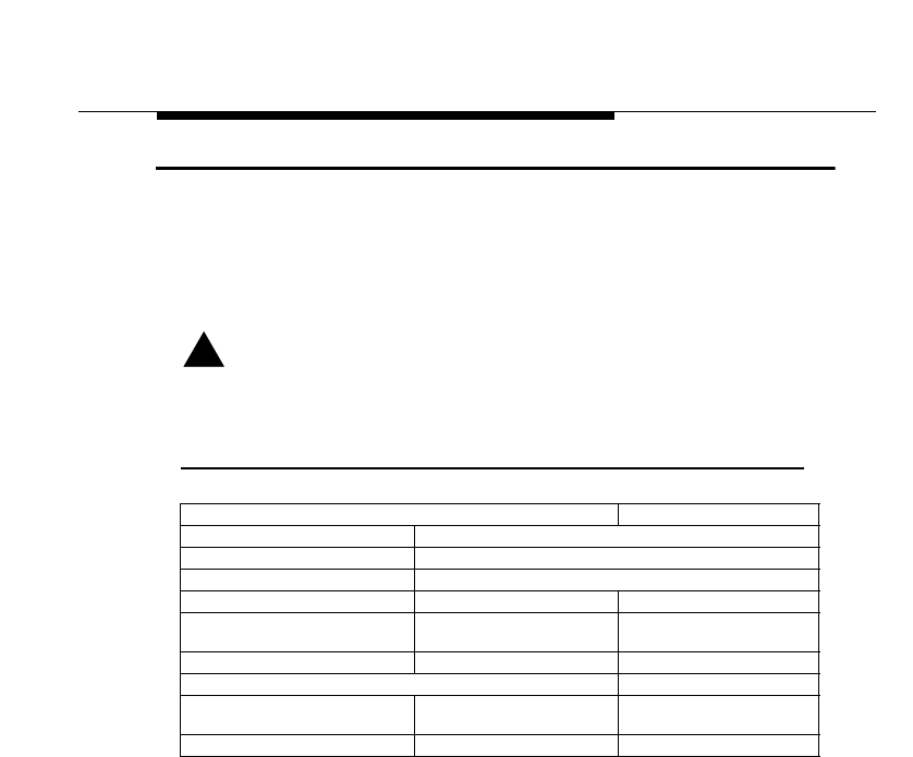
The Antenna Cabling System
Low-Loss Antenna Cable
ORiNOCO Outdoor Antenna Installation Guide A-9
Low-Loss Antenna Cable
The low-loss antenna cable is available in three standard lengths.
■Specifications 6m (20 ft) Antenna Cable.
■Specifications 15m (50 ft) Antenna Cable.
■Specifications 22m (75 ft) Antenna Cable.
!CAUTION:
To ensure you order the right cable length, carefully determine the
distance between the intended locations of the Outdoor Router
hardware and outdoor antenna.
Table A-5 Specifications 6m (20 ft) Antenna Cable.
Mechanical Specifications
Length 6 meter (20 ft)
Connectors1
1 See also “Selecting the Correct Connector-Type” on page A-2
Standard-N (Male on both ends)
Operating Temperature - 40°C to +85°C
Diameter2
2 Use of the 10 mm diameter version of this cable is subject to local radio regulations. Consult
Appendix G “Certified Outdoor Solutions” for information whether you are allowed to use
this cable in your country.
5 mm (0.2 in.) 10 mm (0.4 in.)
Weight 32,75 gram/meter (0.022 lbs/
ft) 101.2 gram/meter (0.068
lbs/ft))
Bend Radius 50 mm (2 in.) 100 mm (4 in.)
Electrical Specifications
Insertion Loss 0.55 dB/meter
(16.9 dB/100 feet) 0.22 dB/meter
(6.8 dB/100 feet)
Total for this cable < 4.0 dB < 2.0 dB
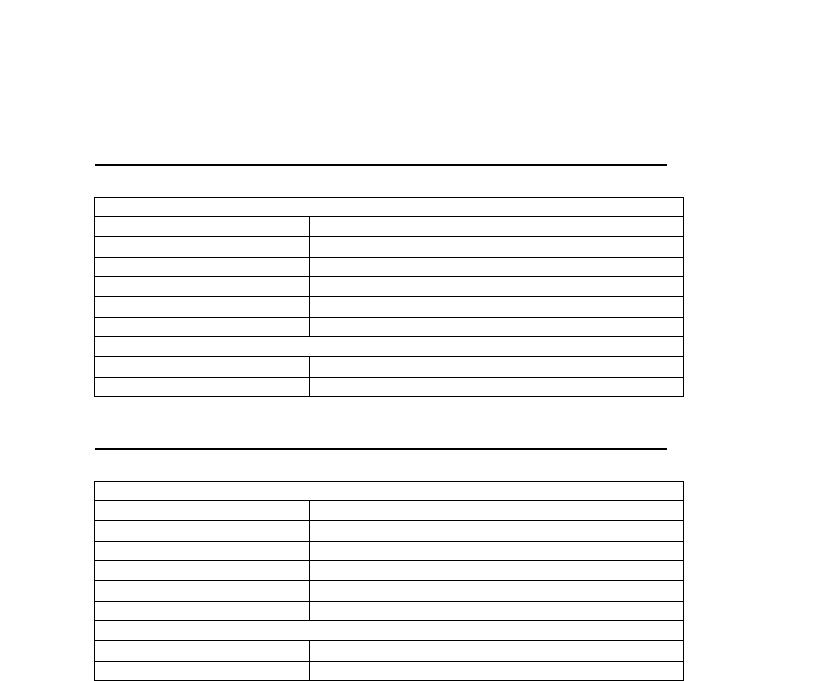
Table A-6 Specifications 15m (50 ft) Antenna Cable
Table A-7 Specifications 22m (75 ft) Antenna Cable
Mechanical Specifications
Length 15 meter (50 ft)
Connectors1
1 See also “Selecting the Correct Connector-Type” on page A-2
Standard-N (Male on both ends)
Operating Temperature - 40°C to +85°C
Diameter 10 mm (0.4 in.)
Weight 101.2 gram/meter (0.068 lbs/ft)
Bend Radius 100 mm (4 in.)
Electrical Specifications
Insertion Loss 0.22 dB/meter (6.8 dB/100 feet)
Total for this cable < 4.0 dB
Mechanical Specifications
Length 22 meter (75 ft)
Connectors1
1 See also “Selecting the Correct Connector-Type” on page A-2
Standard-N (Male on both ends)
Operating Temperature - 40°C to +85°C
Diameter 10 mm (0.4 in.)
Weight 101.2 gram/meter (0.068 lbs/ft)
Bend Radius 100 mm (4 in.)
Electrical Specifications
Insertion Loss 0.22 dB/meter (6.8 dB/100 feet)
Total for this cable < 5.7 dB
ORiNOCO Outdoor Antenna Installation Guide B-1
14 dBi Directional Antenna
General Description
14 dBi Directional Antenna is a High-Gain ORiNOCO Antenna for the 2.4 GHz
frequency band.
This antenna is typically used in combination with ORiNOCO Outdoor Routers in
Remote slave Mode.
The 14 dBi Directional Antenna is a totally enclosed 16 element Yagi antenna
that has been designed for point-to-point communications.
It has a typical VSWR of 1.5:1 and is less than 2:1 over the entire frequency
band. The gain is 14 dBi and the half-power beamwidth is 30 degrees. This
antenna is normally mounted on a mast and is vertically polarized.
Contents of the Antenna Box
■One encapsulated antenna
■Metal Backing Plate for the antenna
■2 U-bolts, with 2 bolt heads (for mast mounting)
■4 flat-washers, and 4 nuts
(to attach the antenna to the U-bolts or screws)
Mounting the Directional Antenna
You can mount the Lucent Technologies 14 dBi Directional Antenna to a mast or
a flat vertical surface, such as a wall.
In most cases mounting the antenna to a mast will allow for more flexibility in
adjusting the height and direction of the antenna to aim it at the opposite end of
the wireless link.
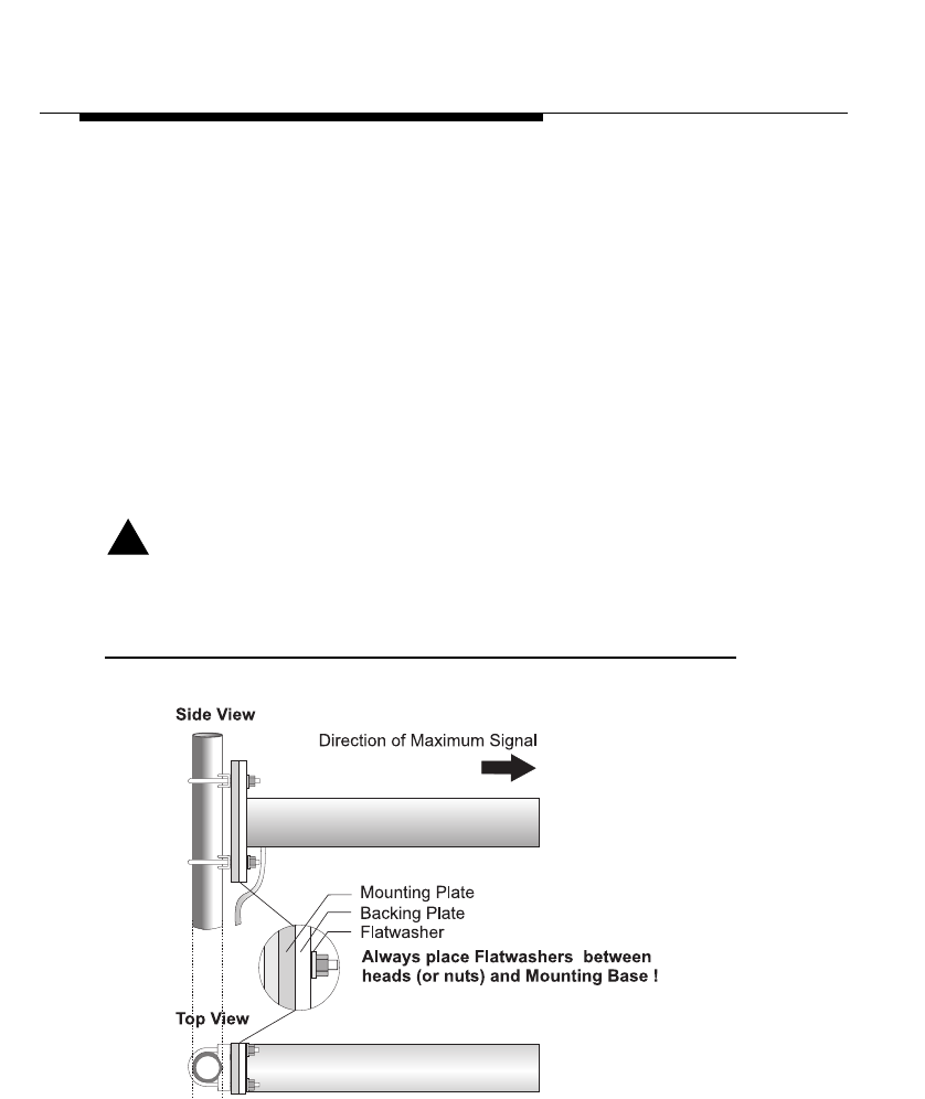
14 dBi Directional Antenna
General Description
B-2 ORiNOCO Outdoor Antenna Installation Guide
Mounting to a Mast
To mount the antenna to a mast proceed as follows:
1. Verify if you have all the items listed below:
■The ORiNOCO 2.4 GHz antenna
■The 2 U-bolts and bolt heads provided
■The 4 flat washers and 4 nuts provided
■A socket wrench to tighten the nuts
2. Note the arrows on the mounting plate.
3. Mount the antenna with the arrows pointing up.
4. Attach the antenna to the mast as pictured in Figure B-1 on page B-2, using
the U-bolts and bolt heads, the Metal Backing Plate and nuts.
5. Proceed with “Connecting the Antenna Cable” on page 4-6.
!CAUTION:
Always place flat washers between heads (or nuts) and the plastic
mounting plate. Avoid overtightening the nuts and screws to prevent
damage to the mounting plate.
Figure B-1 Mounting the 14 dBi Antenna to a Mast
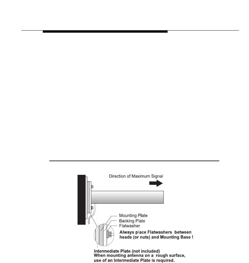
14 dBi Directional Antenna
General Description
ORiNOCO Outdoor Antenna Installation Guide B-3
Mounting on a Flat Surface
For mounting the antenna to a flat vertical surface, you must provide a smooth
surface for the antenna mount. On wall surfaces such as brick, block or stucco,
use an intermediate surface such as a plywood board or metal plate between
the wall and antenna. The intermediate surface will need to be of sufficient
strength to prevent distortion of the antenna base when the mounting hardware
is tightened.
To mount the antenna proceed as follows:
1. Verify if you have all the items listed below:
■The ORiNOCO 2.4 GHz antenna
■(optional) an intermediate plate
■4 plugs and screws
■4 flat washers
■An electric drill
■A screwdriver to tighten the screws
Figure B-2 Mounting the 14 dBi Antenna to a Wall
2. Note the arrows on the mounting plate.
3. Mount the antenna with the arrows pointing up.
4. Attach the antenna using the intermediate plate, Metal Backing Plate and flat
washers as shown in Figure B-2.
5. Proceed with “Connecting the Antenna Cable” on page 4-6.
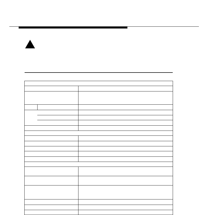
14 dBi Directional Antenna
General Description
B-4 ORiNOCO Outdoor Antenna Installation Guide
!CAUTION:
Always use flat washers between the screws and the plastic mounting
plate. Avoid overtightening nuts and screws to prevent damage to the
mounting plate.
Table B-1 Specifications 14 dBi Directional Antenna
Mechanical
■Size 45.7 cm (18 in.)
■Mounting Method ■Vertical or horizontal mast with an outside diameter
between 28 mm (1.102 in.) and 41 mm (1.625 in.) using
u-bolts.
■Wall using plugs and screws.
Cable ■Type RG-58A/U, 50 ohm low-loss coax
■Length 80 cm (31.5 in.)
■Color White
Connector1
1 See also “Selecting the Correct Connector-Type” on page A-2
Standard-N (Female)
Electrical
■Frequency Range 2.4 GHz
■VSWR Less than 2:1, 1.5:1 Nominal
■Nominal Impedance 50 Ohms
■Gain 14 dBi
■Front-to-Back Ratio greater than 20 dB
Half-Power Beamwidth
■Elevation Plane
(vertical) 30.8 Degrees
■Azimuth Plane
(horizontal) 31.4 Degrees
■Polarization ■Linear Vertical (standard mounting)
■Horizontal (when mounted differently - see “Mounting
the Directional Antenna” on page B-1).
Antenna Environment
■Operating Temperature - 40°C (-40°F) to +60°C (140°F)
■Wind/survival At least 200 km/h (124 mph.)2
2 At least 100 km/h (62 mph) with 1.25 cm (0.5 in.) ice.
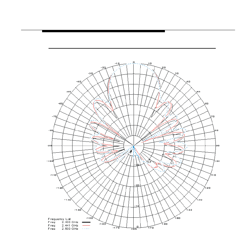
14 dBi Directional Antenna
General Description
ORiNOCO Outdoor Antenna Installation Guide B-5
Figure B-3 Azimuth Plane (Horizontal)
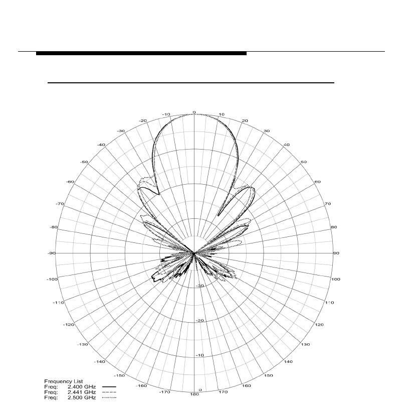
14 dBi Directional Antenna
General Description
B-6 ORiNOCO Outdoor Antenna Installation Guide
Figure B-4 Elevation Plane (Vertical)
ORiNOCO Outdoor Antenna Installation Guide C-1
7 dBi Omni-Directional
Base Station Antenna
Hardware Specifications
The Lucent Technologies 7 dBi Omni-Directional Base Station Antenna is a
broadband antenna for the 2.4 GHz frequency band featuring an omni-
directional pattern with a nominal gain of 7 dBi.
The pole-type antenna is enclosed in a weatherproof protective covering
(“radome”). This vertically polarized antenna can be mounted to an antenna
mast with an outside diameter of up to 65 mm (2.5 in).
For detailed specifications see Table C-1 on page C-3.
Mounting the Omni-directional Antenna
You can mount the 7 dBi MHz antenna to a mast only. This antenna uses
Vertical Polarization which is the most common type of polarization for omni-
directional antennas.
Mounting to a Mast
To mount the antenna to a mast proceed as follows:
1. Verify that you have all the items listed below:
■The ORiNOCO 7 dBi Pole Antenna
■The O-shaped Metal Bracket,.
■The U-bolt, nuts and lock washers
■A small wrench to tighten the nuts
2. Position the Bracket (identified as item D in Figure C-1 on page C-2) to the
top of the antenna mast (item B).
3. Place the U-bolt (item C) around the antenna mast, and slide its ends
through the corresponding holes of the bracket.
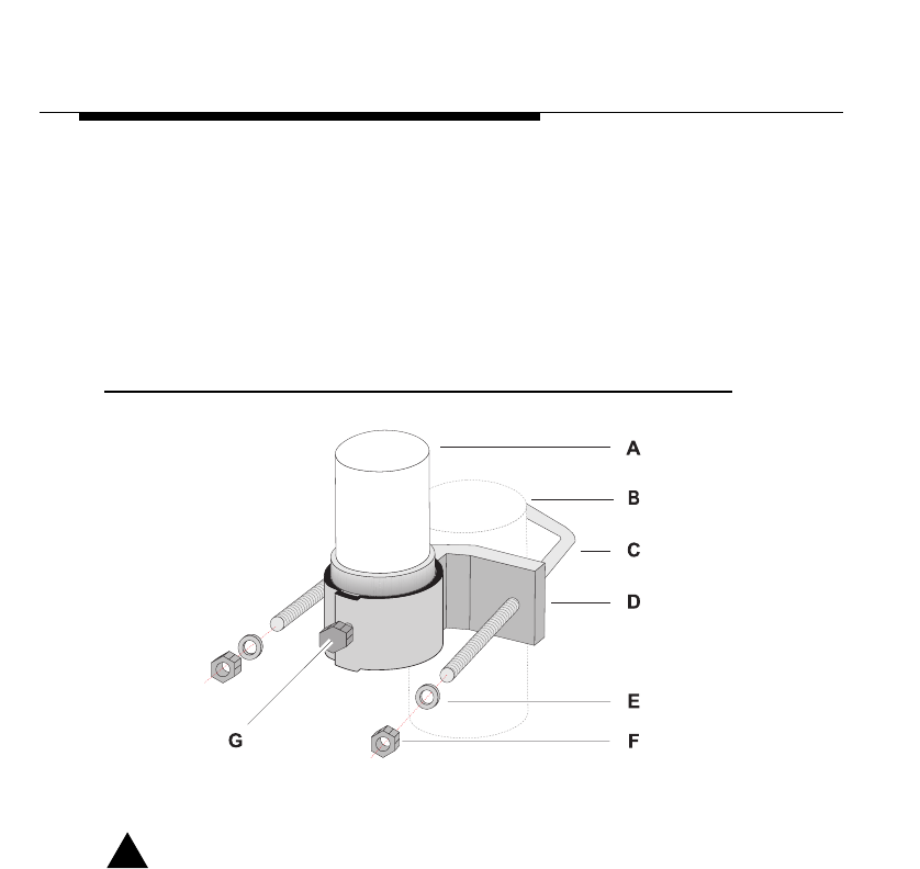
7 dBi Omni-Directional Base Station
Antenna
Hardware Specifications
C-2 ORiNOCO Outdoor Antenna Installation Guide
4. Use the lock-washers (item E) and nuts (item F) to secure the bracket to the
mast.
Use a wrench to tighten the nuts and ensure the bracket will be fixed to the
top of the mast.
5. Next feed the antenna cable of the 7 dBi omni-directional Base Station
antenna (item A) through the hole of the mounting bracket.
6. Slide the antenna down, until its metal base is enclosed by the mounting
bracket as pictured in Figure C-1.
Figure C-1 Mounting the 7 dBi Antenna to a Mast
7. Use a wrench to tighten the bracket bolt (item G) to fix the antenna into its
position.
!CAUTION:
Avoid overtightening the hose-clip nut to avoid damage to the clip and
your antenna.
8. Proceed with “Connecting the Antenna Cable” on page 4-6 to connect the
antenna to the indoor equipment and seal the antenna connectors.
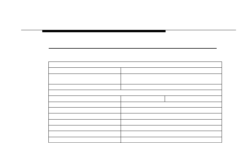
7 dBi Omni-Directional Base Station
Antenna
Hardware Specifications
ORiNOCO Outdoor Antenna Installation Guide C-3
Table C-1 Specifications 7 dBi Omni-Directional Base Station Antenna
Mechanical
■Size 43,2 cm (17 in.)
■Mounting method Clamps to vertical mast with outside diameter between
35 mm (1.4 in.) and 65 mm (2.55 in.)
Connector1
1 See also “Selecting the Correct Connector-Type” on page A-2
Standard-N (female)
Electrical
■Frequency Range 2.4 GHz
■VSWR Less than 2:1 Nominal
■Nominal Impedance 50 Ohms
■Gain 7 dBi
■Polarization Linear Vertical
Antenna Environment
■Operating Temperature - 40°C (-40°F) to +60°C (140°F)
■Wind/survival At least 200 km/h (124 mph)2
2 At least 100 km/h (62 mph) with 1.25 cm (0.5 in.) ice.
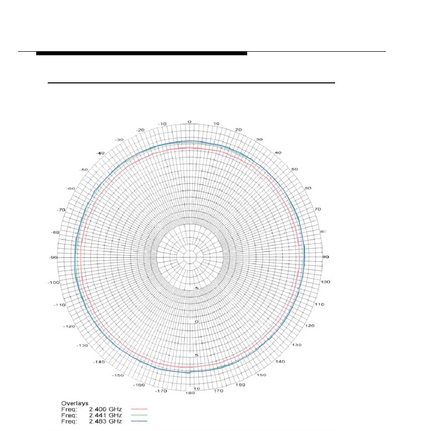
7 dBi Omni-Directional Base Station
Antenna
Hardware Specifications
C-4 ORiNOCO Outdoor Antenna Installation Guide
Figure C-2 Azimuth Plane (Horizontal)
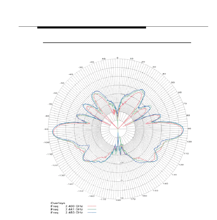
7 dBi Omni-Directional Base Station
Antenna
Hardware Specifications
ORiNOCO Outdoor Antenna Installation Guide C-5
Figure C-3 Elevation Plane (Vertical)

ORiNOCO Outdoor Antenna Installation Guide D-1
10 dBi Omni-Directional
Base Station Antenna
Hardware Specifications
The Lucent Technologies 10 dBi Omni-Directional Base Station Antenna is a
broadband antenna for the 2.4 GHz frequency band featuring an omni-
directional pattern with a nominal gain of 10 dBi.
This antenna is typically used in combination with ORiNOCO/Centrals in Master
mode.
The pole-type antenna is enclosed in a weatherproof protective covering
(“radome”). This vertically polarized antenna can be mounted to an antenna
mast with an outside diameter of up to 51 mm (2.0 in).
For detailed specifications see Table D-1 on page D-2.
!CAUTION:
When selecting an antenna location, please ensure general precautions
so as to avoid possible contact with electrical power lines. Refer to the
National Electrical Code for proper grounding of the antenna mast.
Mounting Instructions
1. Attach the ferrule of the antenna to the mounting bracket with two u-bolts as
shown inFigure D-1 on page D-2.
2. Next use the remaining two u-bolts to attach the mounting bracket to the
mast. Tighten nuts to 9 Nm (7 ft.-lbs).
3. Proceed with “Connecting the Antenna Cable” on page 4-6 to connect the
antenna to the indoor equipment and seal the antenna connectors.
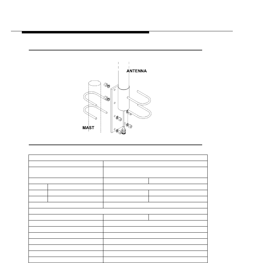
10 dBi Omni-Directional Base Station
Antenna
Hardware Specifications
D-2 ORiNOCO Outdoor Antenna Installation Guide
Figure D-1 Mounting the 10 dBi Antenna
Table D-1 Specifications 10 dBi Omni-Directional Base Station Antenna
Mechanical
■Size 91.4 cm (36 in.)
■Mounting method Clamps to vertical mast with outside diameter between
35 mm (1.4 in.) and 51 mm (2.0 in.)
Cable
■Type RG-303, 50 ohm low-loss coax
■Length 25 cm (10 in.)
■Color Tan
Connector1
1See “Selecting the Correct Connector-Type” on page A-2
Standard-N (female)
Electrical
■Frequency Range 2.4 GHz
■VSWR Less than 2:1 Nominal
■Nominal Impedance 50 Ohms
■Gain 10 dBi
■Polarization Linear Vertical
Antenna Environment
■Operating Temperature +60°C (140°F) - 40°C (-40°F)
■Wind/survival (mph) At least 240 km/h (150 mph)2
2 At least 200 km/h (124 mph) with 1.25 cm (0.5 in.) ice.
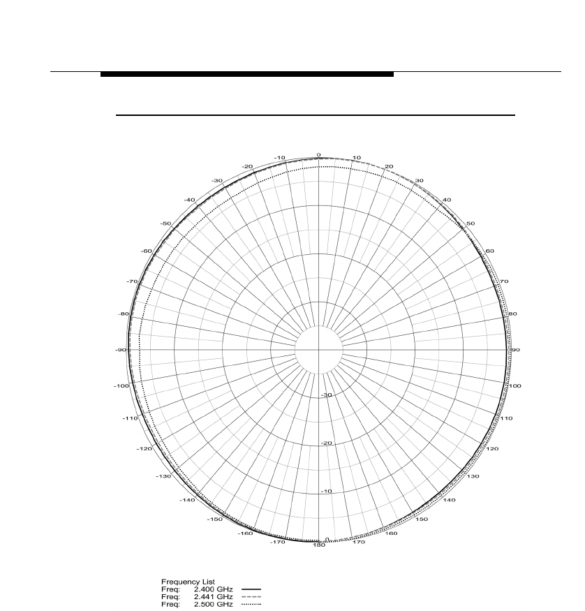
10 dBi Omni-Directional Base Station
Antenna
Hardware Specifications
ORiNOCO Outdoor Antenna Installation Guide D-3
Figure D-2 Azimuth Plane (Horizontal)
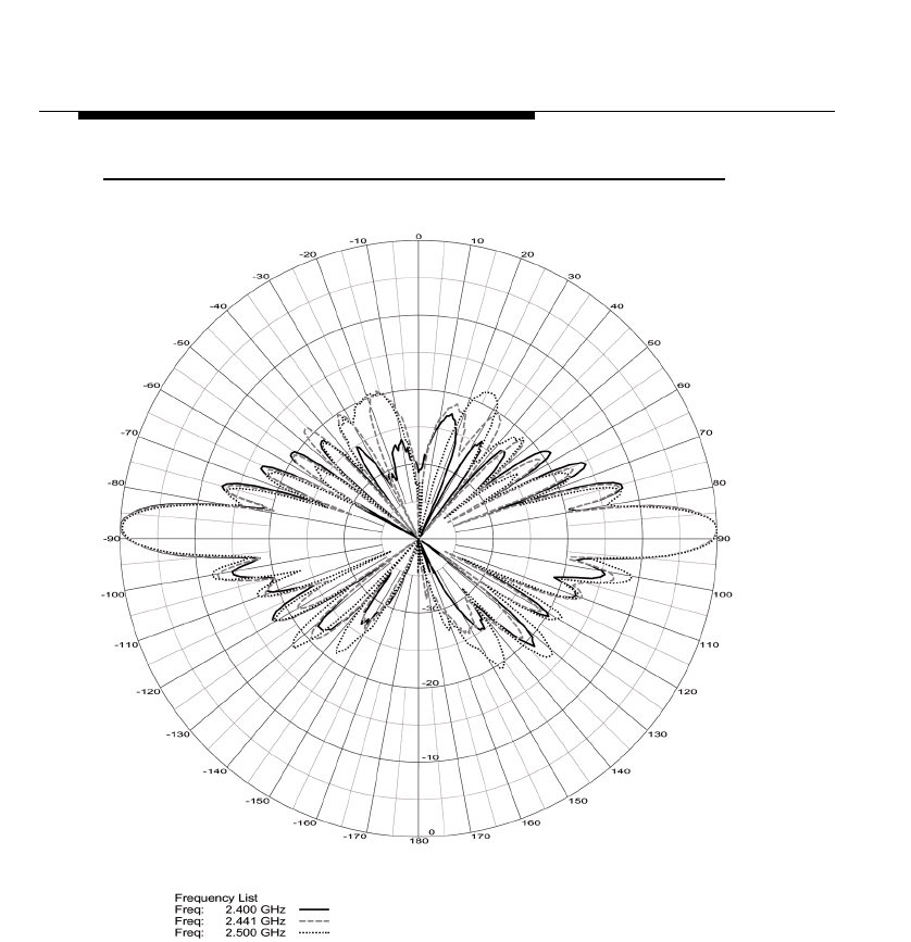
10 dBi Omni-Directional Base Station
Antenna
Hardware Specifications
D-4 ORiNOCO Outdoor Antenna Installation Guide
Figure D-3 Elevation Plane (Vertical)
ORiNOCO Outdoor Antenna Installation Guide E-1
12 dBi Directional Wide
Angle Antenna
Hardware Specifications
The Lucent Technologies 12 dBi Directional Wide Angle Antenna is for the 2.4
GHz frequency band is a perfect match between the features of the:
■Directional Antennas described in Appendix B “14 dBi Directional Antenna”
and Appendix F “24 dBi Directional Parabolic Grid Antenna”
■Omni-Directional Antennas described in Appendix C “7 dBi Omni-Directional
Base Station Antenna” and Appendix D “10 dBi Omni-Directional Base
Station Antenna”.
Typically used in combination with ORiNOCO/Central. This antenna can be
mounted to an antenna mast with an outside diameter of up to 51 mm (2.0 in.).
Mounting Instructions
!CAUTION:
When selecting an antenna location, please ensure General
Precautions are met so as to avoid possible contact with electrical
power lines. Refer to the National Electrical Code for proper grounding
of the antenna mast.
1. Attach the u-bolts, tube mounting bracket, upper mounting bracket, and
lower mounting bracket to the mast and spaced as shown in Figure E-1 on
page E-2.
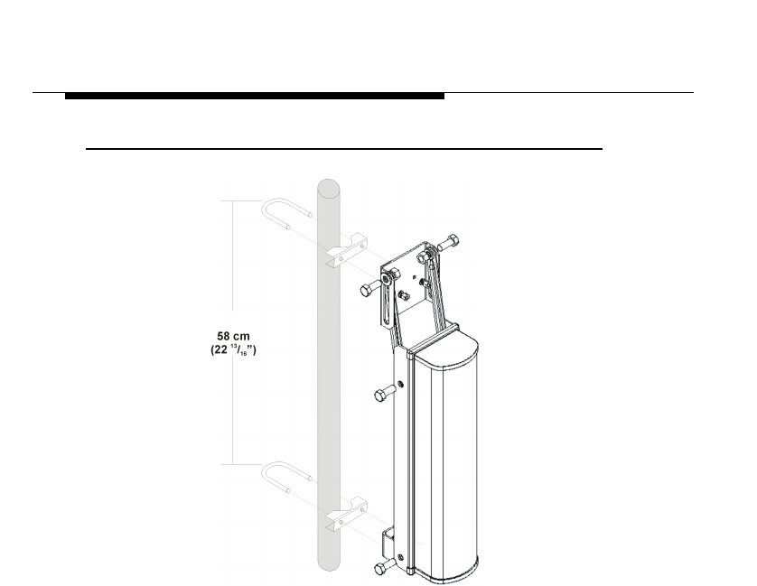
12 dBi Directional Wide Angle Antenna
Hardware Specifications
E-2 ORiNOCO Outdoor Antenna Installation Guide
Figure E-1 Mounting the 12 dBi Wide Angle Antenna
2. Assemble the angle adjustment brackets to the upper mounting bracket with
1/2” bolts, lock washers, flat washers and nuts.
3. Next assemble the angle adjustment brackets and lower mounting brackets
to the antenna base plate with 1/2” bolts, lock washers, and nuts.
This adjustment is for 0 degree mounting.
To adjust from 0 to -20 degrees, loosen the hardware at both ends of the
angle adjustment bracket and slide it in the slot to the preferred angle.
4. Tighten hardware securely. The U-bolts should be tightened to 9 Nm (7 ft.-
lbs).
5. Proceed with “Connecting the Antenna Cable” on page 4-6 to connect the
antenna to the indoor equipment and seal the antenna connectors.
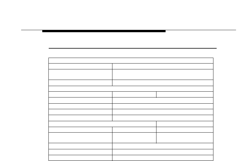
12 dBi Directional Wide Angle Antenna
Hardware Specifications
ORiNOCO Outdoor Antenna Installation Guide E-3
Table E-1 Specifications 12 dBi Directional Wide Angle Antenna
Mechanical
■Size (LxWxD) 181x53.7x76 cm (21.1x7.1x3.0 in.))
■Mounting method Clamps to vertical mast with outside diameter between
35 mm (1.4 in.) and 51 mm (2.0 in.)
Connector1
1 See “Selecting the Correct Connector-Type” on page A-2
Standard-N (female)
Electrical
■Frequency Range 2.4 GHz
■VSWR Less than 2:1 Nominal
■Nominal Impedance 50 Ohms
■Gain 12 dBi
■Polarization Linear Vertical
Half-Power Beamwidth
■Elevation Plane (vertical) 13 Degrees
■Azimuth Plane
(horizontal) 125 Degrees
Antenna Environment
■Operating Temperature +60°C (140°F) - 40°C (-40°F)
■Wind/survival (mph) At least 200 km/h (124 mph)2
2 At least 100 km/h (62 mph) with 1.25 cm (0.5 in.) ice.
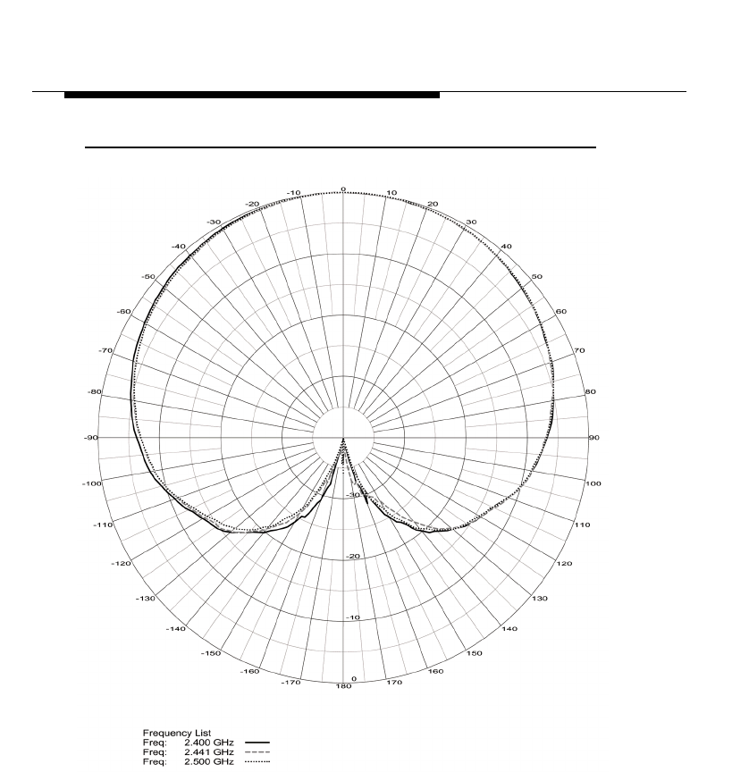
12 dBi Directional Wide Angle Antenna
Hardware Specifications
E-4 ORiNOCO Outdoor Antenna Installation Guide
Figure E-2 Azimuth Plane (Horizontal)
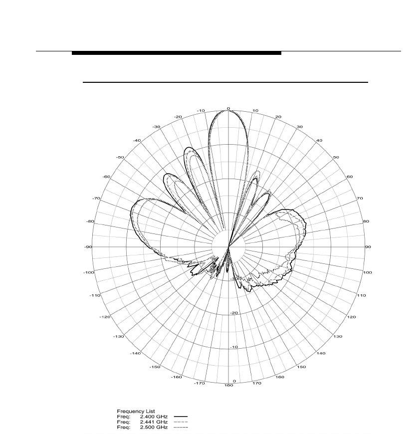
12 dBi Directional Wide Angle Antenna
Hardware Specifications
ORiNOCO Outdoor Antenna Installation Guide E-5
Figure E-3 Elevation Plane (Vertical)

ORiNOCO Outdoor Antenna Installation Guide F-1
24 dBi Directional
Parabolic Grid Antenna
Hardware Specifications
The Lucent Technologies 24 dBi Directional Parabolic Grid Antenna is a
broadband antenna for the 2.4 GHz frequency band.
The grid-type antenna that allows for either horizontal or vertical mounting on a
antenna mast with an outside diameter of up to 51 mm (2 in). For detailed
specifications see Table F-1 on page F-5.
This antenna is typically used in combination with ORiNOCO Outdoor Routers in
Remote slave Mode.
!WARNING:
The 24 dBi Directional Parabolic Grid Antenna is not allowed in
countries that adhere to the ETSI radio regulations, France and Japan.
In countries that adhere to the FCC regulations, use of this antenna is
only allowed when operated with specific ORiNOCO radio channels that
can be set at the ORiNOCO/Outdoor Router. Appendix G “Certified
Outdoor Solutions” describes which channels are allowed or not.
Prior to purchasing or installing the 24 dBi Directional Parabolic Grid
Antenna, please consult “Certified Outdoor Solutions” on page G-1 for
more information.
24 dBi Directional Parabolic Grid Antenna
Hardware Specifications
F-2 ORiNOCO Outdoor Antenna Installation Guide
Kit Contents
The 24 dBi Directional Parabolic Grid Antenna comes in two boxes with the
following contents:
NOTE:
Prior to installation, or climbing the roof, verify if all parts and
components are included. If any part is missing or appears to be
damaged, please consult your authorized Lucent Technologies Reseller.
Assembling the Antenna
1. Assemble the two halves inserting the 4 #8-32 machine screws through the
front. Secure with the keps nuts on the back.
NOTE:
Loosely tighten all hardware until completely assembled and then
tighten securely.
PACKED IN FEED BOX: PACKED IN REFLECTOR BOX
■1 Feed assembly
■1 Sub-reflector
■1 #6 x 1/2” stainless screw
■2 Stainless 1/4 x 20 hex nuts
■2 Stainless lock washers
■2 Stainless carriage bolts
■2 Reflector halves
■2 Stainless U-bolts
■2 Mast clamps
■1 Mounting “L” shaped bracket
■4 Keps nuts (4) #8-32 machine screws
■6 Stainless 1/4 x 20 hex nuts
■6 Stainless lock washers
■2 Stainless carriage bolts
■1 Stainless flat plate washer
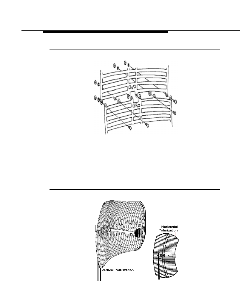
24 dBi Directional Parabolic Grid Antenna
Hardware Specifications
ORiNOCO Outdoor Antenna Installation Guide F-3
Figure F-1 Assemble the Reflector
2. Place the sub-reflector on the front of the feed and secure with the #6 x 1/
2”stainless screw.
3. Determine the polarity of the antenna (see Figure F-2).
■Horizontal Polarity, (the reflector ribs and the sub reflector at the front
end of the antenna are aligned horizontally).
■Vertical Polarity: (the reflector ribs and the sub reflector at the front end
of the antenna are aligned vertically).
Figure F-2 Determine Polarization
Polarity of the antenna must always be the same as the polarity of the
antenna on the opposite side of the link!
4. Place the “L” bracket on the back of the antenna.
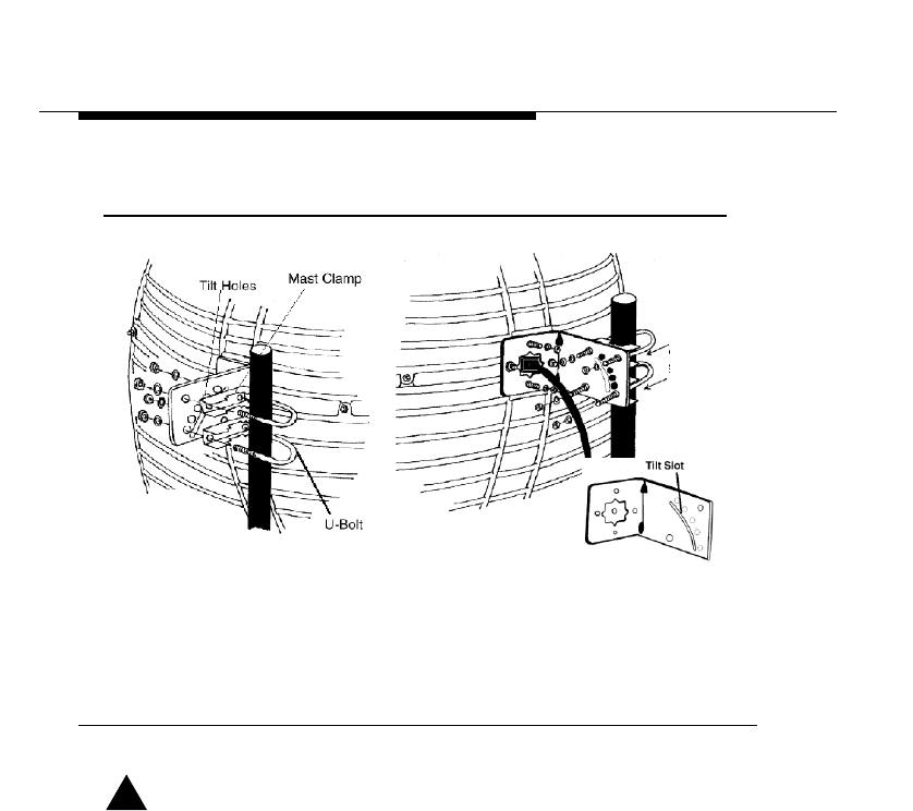
24 dBi Directional Parabolic Grid Antenna
Hardware Specifications
F-4 ORiNOCO Outdoor Antenna Installation Guide
5. Insert two carriage bolts from the front to attach.
Figure F-3 Attach the mounting Bracket
6. Secure on the back with the lock washers and nuts as pictured in
Figure F-3).
7. Re-check the dipole feed assembly for the proper polarity.
8. Attach the feed on the front with 2 carriage bolts. Secure on the back with the
lock washers and nuts.
Mounting the Antenna
!DANGER:
Installation of antenna near power lines is dangerous! Before you
proceed, make sure you have read and understood the safety
precautions as described in Chapter 2 “Preparing for Installation”.
1. Before climbing the roof, make sure you have:
■The assembled antenna
■The U-bolts and mast clamps to mount the grid antenna to the mast.
2. Determine the desired alignment of the antenna:
■For horizontal alignment you will need both U-bolts and the 4 lock
washers and nuts.
■For tilted alignment, you will only use a single U-bolt and two lock
washers and nuts. This mounting method allows you to mount the
antenna with an elevation in 100 degree increments
24 dBi Directional Parabolic Grid Antenna
Hardware Specifications
ORiNOCO Outdoor Antenna Installation Guide F-5
!WARNING:
Tilted alignment is not suitable for environments where the antenna is
subject to high wind conditions.
3. Place the U-bolt(s) around the mast as pictured in Figure F-3 on page F-4.
4. Slide the mast clamps over the U-bolts as pictured in Figure F-3 on
page F-4.
5. Finally slide the “L”-Bracket over the U-bolts, and fasten the grid antenna to
the U-bolts using the lock washers and nuts.
For tilted elevation mounting, use the flat plate washer on the adjustable tilt
slot to mount and secure the antenna to the desired elevation angle.
6. Proceed with “Connecting the Antenna Cable” on page 4-6 to connect the
antenna to the indoor equipment and seal the antenna connectors.
Table F-1 Specifications 24 dBi Directional Parabolic Grid Antenna
Mechanical
■Size (HxWxD) 61,0x91,4x38,1 cm (24x36x15 in.)
■Mounting method Clamps to vertical mast with outside diameter between
26 mm (1.102 in.) and 51 mm (2.0 in.)
Cable ■Type RG-8A/U, 50 ohm low-loss coax
■Length 60 cm (24 in.)
■Color Black
Connector1
1 See “Selecting the Correct Connector-Type” on page A-2
Standard-N (female)
Electrical
■Frequency Range 2.4 GHz
■VSWR Less than 2:1 Nominal
■Nominal Impedance 50 Ohms
■Gain 24 dBi
■Polarization ■Linear Vertical for standard mounting
■Horizontal when mounted differently (see “Mounting
the Antenna” on page F-4)
Half-Power Beamwidth (at vertical polarization)
■Elevation Plane (vertical) 10 Degrees
■Azimuth Plane (horizontal) 6.5 Degrees
Antenna Environment
■Operating Temperature +60°C (140°F) - 40°C (-40°F)
■Wind/survival (mph) At least 200 km/h (124 mph)2
2 At least 100 km/h (62 mph) with 1.25 cm (0.5 in.) ice.
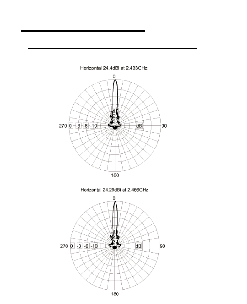
24 dBi Directional Parabolic Grid Antenna
Hardware Specifications
F-6 ORiNOCO Outdoor Antenna Installation Guide
Figure F-4 Azimuth Plane (Horizontal)
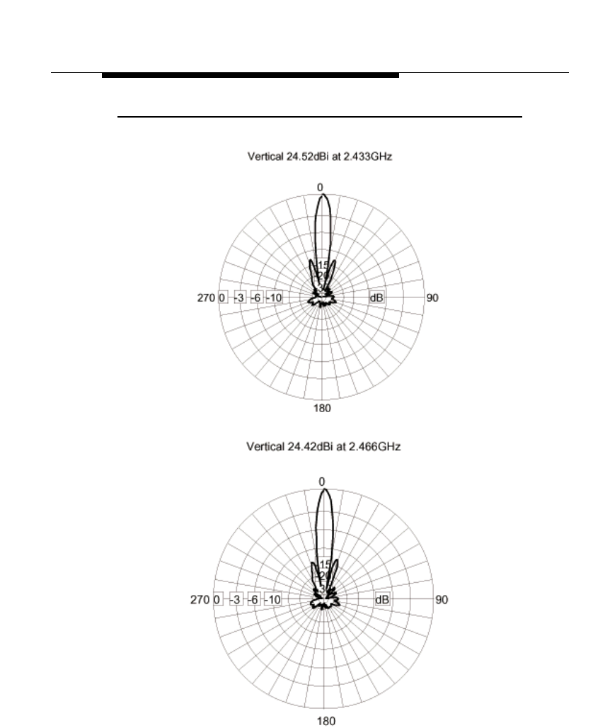
24 dBi Directional Parabolic Grid Antenna
Hardware Specifications
ORiNOCO Outdoor Antenna Installation Guide F-7
Figure F-5 Elevation Plane (Vertical)

ORiNOCO Outdoor Antenna Installation Guide G-1
Certified Outdoor
Solutions
Introduction
As radio regulations differ between the various countries world-wide, not all of
the outdoor solutions described in this ORiNOCO Outdoor Antenna Installation
Guide may be allowed in the country where you plan to install this equipment.
Local radio regulations or legislation may impose restrictions on the use of
specific combinations of:
■PC Cards and Outdoor Antennas
■Low-loss antenna cables and Outdoor Antennas
■Radio channels selected at ORiNOCO Outdoor Router devices that are
connected to specific Outdoor Antennas.
NOTE:
Basic rule for selecting a combination of cards, cables and antennas is
that no combination is allowed unless explicitly approved in this
ORiNOCO Outdoor Antenna Installation Guide. Therefore, always use
this Appendix in combination with Chapter 3 “Determine Range &
Clearance” of this document to:
■Select the right type of antenna equipment
■Inform your antenna installer and/or LAN Administrator about the
impact of regulatory constraints on their job/activities.
Certified Outdoor Solutions
Introduction
G-2 ORiNOCO Outdoor Antenna Installation Guide
!WARNING:
At all times, it will be the responsibility of the end-user to ensure that an
outdoor antenna installation complies with local radio regulations.1
The end-user must verify that:
■The antenna installer is aware of these regulations.
■The correct type of ORiNOCO card is used to connect the host
device to the outdoor antenna installation.
■The correct type of cables and surge arrester have been used,
according to the instructions described in this document.
Lucent Technologies and its resellers or distributors are not liable for
any damage or violation of government regulations that may arise from
failing to comply with these guidelines.
1 In case you are not certain about the regulations that apply in your country, consult your local
Lucent Technologies Sales Office.

Certified Outdoor Solutions
Selecting the Right Card & Cables
ORiNOCO Outdoor Antenna Installation Guide G-3
Selecting the Right Card & Cables
To comply with local radio regulations, Lucent Technologies offers two types of
ORiNOCO Cards, that can be used to connect a Outdoor Router or other
computing device to an outdoor antenna installation:
■Standard black-colored ORiNOCO PC Card
■Red-colored ORiNOCO Fixed Wireless PC Card
Also are the low-loss antenna cables available in various lengths and diameters:
■6 m (15 ft.) with a diameter of 5 mm (0.2 in.)1
■6 m (15 ft.) with a diameter of 10 mm (0.4 in.)
■15 m (50 ft.) with a diameter of 10 mm (0.4 in.)
■22 m (75 ft.) with a diameter of 10 mm (0.4 in.)
When you order the ORiNOCO outdoor antenna equipment, make sure that you
order card & cables that comply with the regulations that apply in your country. In
case of doubt, please consult the Lucent Technologies Sales office for more
information.
FCC Regulated Countries
In countries that adhere to the regulations as defined by the US Federal
Communications Commission (FCC), you can use the standard black-colored
ORiNOCO PC Card in combination with all antennas. However restrictions apply
when using the card in combination with the 24 dBi Directional Parabolic Grid
Antenna (consult Table G-2 on page G-5 for allowed channel settings).
1 The cable-loss of this cable is equal to the loss of the 15 m (50 ft.) cable.

Certified Outdoor Solutions
Selecting the Right Card & Cables
G-4 ORiNOCO Outdoor Antenna Installation Guide
ETSI Regulated Countries
In countries that adhere to the regulations as defined by the European
Telecommunications Standards Institute (ETSI), France and Japan, you must
select the card-type based upon the antenna and cable that will be used.
■The 24 dBi Directional Parabolic Grid Antenna is not allowed in ETSI
countries, france or Japan.
■For ETSI/France and Japan radio approvals, the various card/cable/antenna
combinations have all been certified with the red-colored ORiNOCO Fixed
Wireless PC Card.
■The only antenna/cable combination that allows for using a black-colored
ORiNOCO PC Cards, is the 7 dBi Omni-Directional Base Station Antenna in
combination with the 6m (20ft) cable with 5 mm (0.2 in.) diameter, or the 15
m (50ft.) or 25 m (75 ft.) cables.
Consult Table G-3 on page G-6 for allowed combinations.
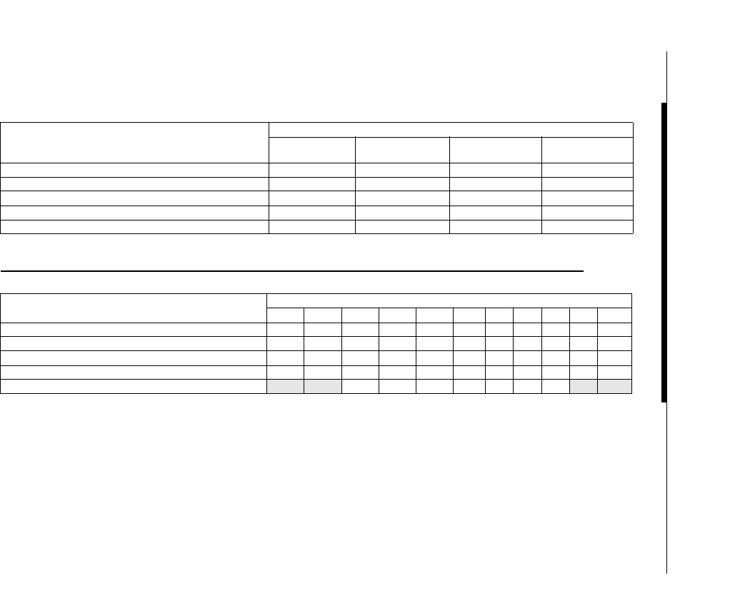
Certified Outdoor Solutions
Selecting the Right Card & Cables
ORiNOCO Outdoor Antenna Installation Guide G-5
Table G-1 Certified Cable/Antenna Combinations FCC
Table G-2 Certified Channel/Antenna Combinations FCC
Antenna Antenna Cable type
6m (20 ft.)
5 mm (0.4 in.) 6m (20 ft.)
10 mm (0.4 in.) 15m (50 ft.)
10 mm (0.4 in.) 25m (75 ft.)
10 mm (0.4 in.)
7 dBi Omni-Directional Base Station Antenna NA Yes Yes Yes
10 dBi Omni-Directional Base Station Antenna NA Yes Yes Yes
12 dBi Directional Wide Angle Antenna NA Yes Yes Yes
14 dBi Directional Antenna NA Yes Yes Yes
24 dBi Directional Parabolic Grid Antenna1
1 Consult Table G-2 for restrictions on channel selection
NA Yes Yes Yes
Antenna Frequency Channels
1234567891011
7 dBi Omni-Directional Base Station Antenna Yes Yes Yes Yes Yes Yes Yes Yes Yes Yes Yes
10 dBi Omni-Directional Base Station Antenna Yes Yes Yes Yes Yes Yes Yes Yes Yes Yes Yes
12 dBi Directional Wide Angle Antenna Yes Yes Yes Yes Yes Yes Yes Yes Yes Yes Yes
14 dBi Directional Antenna Yes Yes Yes Yes Yes Yes Yes Yes Yes Yes Yes
24 dBi Directional Parabolic Grid Antenna No No Yes Yes Yes Yes Yes Yes Yes No No
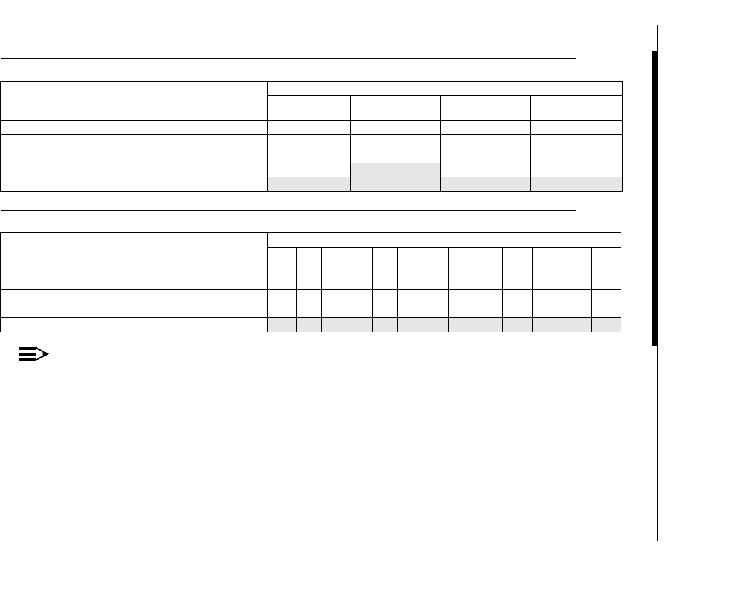
Certified Outdoor Solutions
Selecting the Right Card & Cables
G-6 ORiNOCO Outdoor Antenna Installation Guide
Table G-3 Certified Cable/Antenna Combinations ETSI
Table G-4 Certified Channel/Antenna Combinations ETSI
NOTE:
All solutions listed in the tables above are based on combinations using the ORiNOCO Fixed Wireless
PC Card (red antenna cap), unless indicated otherwise.
Antenna Antenna Cable type
6m (20 ft.)
5 mm (0.2 in.) 6m (20 ft.)
10 mm (0.4 in.) 15m (50 ft.)
10 mm (0.4 in.) 25m (75 ft.)
10 mm (0.4 in.)
7 dBi Omni-Directional Base Station Antenna Yes (black card) Yes Yes (black card) Yes (black card)
10 dBi Omni-Directional Base Station Antenna Yes Yes Yes Yes
12 dBi Directional Wide Angle Antenna Yes Yes Yes Yes
14 dBi Directional Antenna Yes No Yes Yes
24 dBi Directional Parabolic Grid Antenna No No No No
Antenna Frequency Channels
1 2345678 910111213
7 dBi Omni-Directional Base Station Antenna Yes Yes Yes Yes Yes Yes Yes Yes Yes Yes Yes Yes Yes
10 dBi Omni-Directional Base Station Antenna Yes Yes Yes Yes Yes Yes Yes Yes Yes Yes Yes Yes Yes
12 dBi Directional Wide Angle Antenna Yes Yes Yes Yes Yes Yes Yes Yes Yes Yes Yes Yes Yes
14 dBi Directional Antenna Yes Yes Yes Yes Yes Yes Yes Yes Yes Yes Yes Yes Yes
24 dBi Directional Parabolic Grid Antenna No No No No No No No No No No No No No

Certified Outdoor Solutions
Regulatory Information
ORiNOCO Outdoor Antenna Installation Guide G-7
Regulatory Information
The Lucent Technologies outdoor antenna solution must be installed and used in
strict accordance with the instructions as described in this ORiNOCO Outdoor
Antenna Installation Guide.
For country-specific approvals, please consult the flyer "Information to the User"
that was shipped with your ORiNOCO PC Card.
Please Note:
Radio approvals for the Lucent Technologies outdoor antenna solution are valid
only when using the exact combination of Lucent Technologies PC Cards,
outdoor antenna cabling components and antennas as listed in this ORiNOCO
Outdoor Antenna Installation Guide.
Using other combinations of parts and components in outdoor antenna solutions
will void the radio type approval and may be in violation of local radio
regulations.
Lucent Technologies and its authorized resellers or distributors are not liable for
any damage or violation of government regulations that may arise from failing to
comply with these guidelines.

Support & Warranty
Technical Support
If you encounter problems when installing or using this product, please consult
the ORiNOCO website at: http://www.lucent.com/orinoco for:
■the latest software, user documentation and product updates
■the Frequently Asked Questions (FAQ)
Alternatively please contact your local authorized ORiNOCO reseller for
Technical Support.
Help us helping you by completing the ORiNOCO problem report form and
include it with your e-mail or fax when contacting Technical Support.
You can find the problem report form (report.txt) on:
■the ORiNOCO CD-ROM, and
■the support pages of the ORiNOCO website.
Addresses of authorized ORiNOCO resellers are listed in the “Contact &
Ordering” section of the ORiNOCO website.

Support & Warranty
Warranty and Repair
Warranty and Repair
If it appears that your unit needs a repair or replacement, return to your Dealer/
Distributor in its original packaging.
When returning a defective product for Warranty, always include the following
documents:
■The Warranty Repair card (last page of this appendix), and
■A copy of the invoice/proof of purchase
■Problem Report Form (see “Technical Support” on page H-1“).
Lucent Technologies extends a limited warranty from date of purchase of:
■Thirty-six (36) months for ORiNOCO hardware products
■Twelve (12) months for the ORiNOCO Access Points and Outdoor Routers
■Twelve (12) months for the media on which the software is furnished and the
reproduction of the software on the media.
Upon proof-of-purchase Lucent Technologies shall at its option, repair or replace
the defective item at no cost to the buyer.
Defective items shall be returned to the dealer/distributor:
■Freight prepaid.
■Accompanied by a copy of proof-of-purchase.
■Accompanied by a filled out Warranty/Repair card.
This warranty is contingent upon proper use in the application for which the
products are intended and does not cover products which have been modified
without the seller’s approval or which have been subjected to unusual physical
or electrical demands or damaged in any way.
This Warranty constitutes the sole and exclusive remedy of any buyer or
seller’s equipment and the sole and exclusive liability of Lucent Technologies
in connection with the products and is in lieu of all other warranties, express,
implied or statutory, including, but not limited to, any implied warranty of
merchantability of fitness for a particular use and all other obligations or
liabilities of Lucent Technologies.
In no event will Lucent Technologies Inc. or any other party or person be liable
to you or anyone else for any damages, including lost profits, lost savings or
other incidental or consequential damages, or inability to use the software
provided on the software media even if Lucent Technologies or the other party
person has been advised of the possibility of such damages.

Support & Warranty
Warranty and Repair
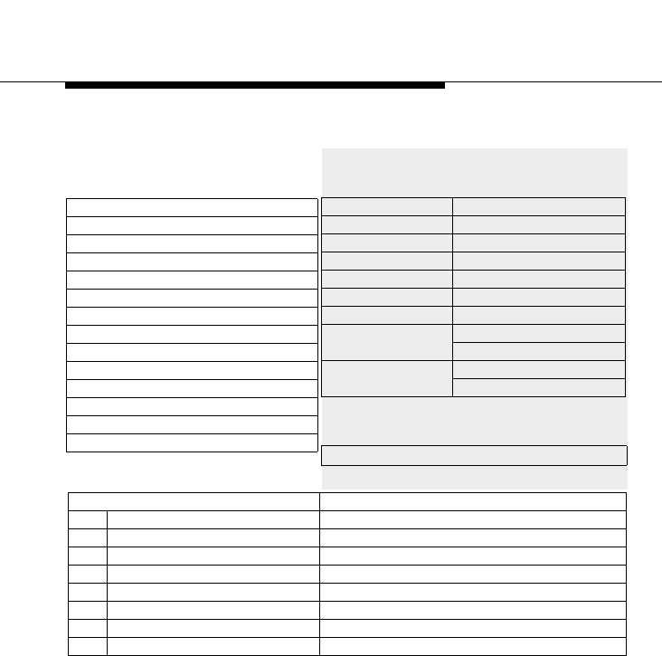
Support & Warranty
Warranty and Repair
ORiNOCO Outdoor Antenna Installation Guide H-4
Reported Problem: Problem Description:
❑Out-of-Box Failure
❑Other
To be filled out by the User:
Product Description:
COMCODE (Product ID):
Serial Number:
Invoice Date: (dd/mm/yyyy)
Name:
Title:
Company:
Address:
City/State/Zipcode:
Country:
Telephone:
Fax:
Email:
To be filled out by the Dealer/
Distributor:
Return Approval Reference:
Dealer Name:
Address:
City/State/Zipcode:
Country:
Telephone:
Fax:
Warranty Comment
❑ Yes
❑ No

ORiNOCO Outdoor Antenna Installation Guide IX-1
A
Antenna
alignment 2-12
cable A-9
cable routing 2-14
connecting 4-6
connectors C-3
mounting 4-5
mounting directional B-1
mounting omni-directional C-1
placement 2-8
Antenna Cable
15 m (50 ft) A-10
22m (75 ft) A-10
6 m (20 ft) A-9
routing 2-6
sealing connectors 4-7
Antenna Mast
grounding 2-12
placement 2-11
requirements 2-11
wall (side) mount 2-11
Antenna Radiation Patterns B-5, B-6,
C-4, C-5, D-3, D-4, E-4, E-5,
F-6, F-7
Antenna, polarization 2-13
Azimuth Plane B-5, C-4
C
Cable Assembly, specifications A-6
Cable Factor 3-7
Check-List 2-15
Clearance 3-9
areas with obstacles 3-10
dense urban areas 3-10
determine 3-1
line-of-sight 2-10
open areas 3-10
Clearance Factor 3-8
Connector
antenna B-4
Connectors
antenna cable A-9
Surge Arrester A-8
D
Diagnostics
OR Manager 2-12
E
Elevation Plane B-6, C-5, D-4, E-5,
F-7
F
Fresnel Zone 3-9
G
Gain 3-1
Grounding System 2-12
H
Horizontal Plane, see Azimuth Plane
B-5, C-4, D-3, E-4, F-6
Index

Index
IX-2 ORiNOCO Outdoor Antenna Installation Guide
I
Information, diskettes 1-3
Information, finding additional 1-2
Installation, overview outdoor 2-8
Installation, site prerequisites 2-1
L
Lightning Protector
see Surge Arrester 2-5
specifications A-8
M
Mounting
directional antenna B-1
O
OR Manager
tool 2-12
User’s Guide 2-12
Wireless Link Test 2-13
ORiNOCO Surge Arrester A-7
Outdoor Router
hardware 2-3
hardware installation 2-5
placement 2-3
Output Power 3-1
P
Performance
seasonal factors 2-10
weather conditions 2-10
Point-to-Point 1-4
R
Range 3-2
Cable Factor 3-7
calculating 3-2
Clearance Factor 3-8
Remote Link Test
see Wireless Link Test 2-12
Remote Outdoor Router 1-4
RF Obstacles 2-9
S
Safety, precautions 4-1
Sealing 4-7
Sensitivity 3-1
Specifications
15m (50 ft) cable A-10
22m (75 ft) cable A-10
6m (20 ft) cable A-9
cable assembly A-6
Surge Arrester A-8
Surge Arrester
placement 2-5
V
Vertical Plane, see Elevation Plane
B-6, C-5, D-4, E-5, F-7

ORiNOCO Outdoor Antenna Installation Guide LOF-1
Figure 1-1 ORiNOCO Point-to-Point Link 1-4
Figure 1-2 ORiNOCO Point-to-Multipoint Link 1-5
Figure 2-1 Overview Indoor Installation of the Outdoor Router 2-2
Figure 2-2 Overview Indoor Installation Outdoor Router Client 2-4
Figure 2-3 Potential Obstacles for a Directional Antenna 2-9
Figure 2-4 OR Manager Wireless Link Test 2-13
Figure 3-1 Fresnel Zone 3-9
Figure 3-2 Clearance Factor Diagram 3-11
Figure 3-3 Calculating the Point-to-Point Range 3-13
Figure 3-4 Calculating the Point-to-Multipoint Range 3-16
Figure A-1 Mounting the ORiNOCO Surge Arrester A-7
Figure B-1 Mounting the 14 dBi Antenna to a Mast B-2
Figure B-2 Mounting the 14 dBi Antenna to a Wall B-3
Figure B-3 Azimuth Plane (Horizontal) B-5
Figure B-4 Elevation Plane (Vertical) B-6
Figure C-1 Mounting the 7 dBi Antenna to a Mast C-2
Figure C-2 Azimuth Plane (Horizontal) C-4
Figure C-3 Elevation Plane (Vertical) C-5
Figure D-1 Mounting the 10 dBi Antenna D-2
Figure D-2 Azimuth Plane (Horizontal) D-3
Figure D-3 Elevation Plane (Vertical) D-4
Figure E-1 Mounting the 12 dBi Wide Angle Antenna E-2
Figure E-2 Azimuth Plane (Horizontal) E-4
Figure E-3 Elevation Plane (Vertical) E-5
Figure F-1 Assemble the Reflector F-3
Figure F-2 Determine Polarization F-3
Figure F-3 Attach the mounting Bracket F-4
Figure F-4 Azimuth Plane (Horizontal) F-6
Figure F-5 Elevation Plane (Vertical) F-7
List of Figures


ORiNOCO Outdoor Antenna Installation Guide LOT-1
Table 3-1 Maximum Outdoor Range for FCC Products 3-5
Table 3-2 Maximum Range for ETSI/FR/JP Products 3-6
Table 3-3 Calculate the Cable Factor 3-7
Table 3-4 FCC Outdoor Range with 10 m (33 ft.) Clearance 3-12
Table A-1 Standard N-Type Connector Diagram A-3
Table A-2 Reverse Polarity-N Cabling Diagram A-4
Table A-3 Specifications Cable Assembly A-6
Table A-4 Specifications Surge Arrester A-8
Table A-5 Specifications 6m (20 ft) Antenna Cable. A-9
Table A-6 Specifications 15m (50 ft) Antenna Cable A-10
Table A-7 Specifications 22m (75 ft) Antenna Cable A-10
Table B-1 Specifications 14 dBi Directional Antenna B-4
Table C-1 Specifications 7 dBi Omni-Directional Base Station Antenna C-3
Table D-1 Specifications 10 dBi Omni-Directional Base Station Antenna D-2
Table E-1 Specifications 12 dBi Directional Wide Angle Antenna E-3
Table F-1 Specifications 24 dBi Directional Parabolic Grid Antenna F-5
Table G-1 Certified Cable/Antenna Combinations FCC G-5
Table G-2 Certified Channel/Antenna Combinations FCC G-5
Table G-3 Certified Cable/Antenna Combinations ETSI G-6
Table G-4 Certified Channel/Antenna Combinations ETSI G-6
List of Tables
