Agfa NV 5365 Drystar 5300/xxx tabletop printer User Manual 2923 B EN PnP Drystar 5300 A5
Agfa Gevaert N V Drystar 5300/xxx tabletop printer 2923 B EN PnP Drystar 5300 A5
Agfa NV >
Contents
- 1. User manual part 1
- 2. User manual part 2
- 3. User manual part 3
- 4. User manual part 4
User manual part 1
Plug & Play
Installation manual
English edition
AGFA Drystar 5300
2923B EN 20031206
Drystar 5300
User manual
Drystar 5300
Reference manual
Health Care
DECLARATION OF CONFORMITY
XXXXXX XXXX XXXXXX XXXXXX XXXX XXXXXX
XXXXXX XXXX XXXXXX XXXXXX XXXX XXXXXX
XXXXXX XXXX XXXXXX XXXXXX XXXX XXXXXX
XXXXXX XXXX XXXXXX
XXXXXX XXXX XXXXXX
XXXXXX XXXX XXXXXX
XXXXXX XXXX XXXXXX
XXXXXX XXXX XXXXXX XXXXXX XXXX XXXXXX
POWER
POWER
POWER

2/16 2923B EN 20031206
❖The device must only be operated according to its specifications and its intended use. Any
operation not corresponding to the specifications or intended use may result in hazards, which in
turn may lead to serious injuries or fatal accidents (for example electric shock). AGFA positively will
not assume any liability in these cases.
❖The device must only be installed and put into operation under the specified conditions.
For more information about safety, security and use, refer to the Drystar 5300 Reference and User
manual.
For more information on Agfa products and Agfa HealthCare products, please visit www.agfa.com, your Point of Knowledge.
© Agfa-Gevaert N.V. 2003.
No parts of this document may be reproduced, copied, adapted or transmitted in any form or by any means without the written
permission of Agfa-Gevaert N.V.
Agfa-Gevaert N.V. makes no warranties or representation, expressed or implied, with respect to the accuracy, completeness or
usefulness of the information contained in this document and specifically disclaims warranties of suitability for any particular purpose.
Agfa-Gevaert N.V. shall under no circumstances be liable for any damage arising from the use or inability to use any information,
apparatus, method or process disclosed in this document.
Agfa-Gevaert N.V. reserves the right to make changes to this document without prior notice.
Agfa-Gevaert N.V., Septestraat 27, B-2640 Mortsel, Belgium.
Drystar 5300 is a trademark of Agfa-Gevaert N.V., Belgium.
Agfa and the Agfa-Rhombus are trademarks of Agfa-Gevaert AG, Germany.
3/16
2923B EN 20031206
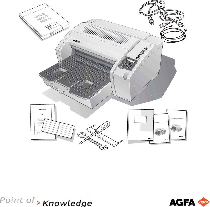
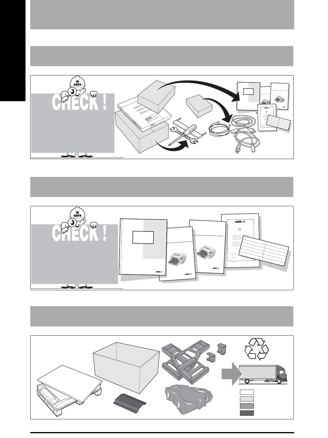
1Contents of the packages
DECLARATION OF CONFORMITY
XXXXXX XXXX XXXXXX XXXXXX XXXX XXXXXX
XXXXXX XXXX XXXXXX XXXXXX XXXX XXXXXX
XXXXXX XXXX XXXXXX XXXXXX XXXX XXXXXX
XXXXXX XXXX XXXXXX
XXXXXX XXXX XXXXXX
XXXXXX XXXX XXXXXX
XXXXXX XXXX XXXXXX
XXXXXX XXXX XXXXXX XXXXXX XXXX XXXXXX
Drystar 5300
User manual
Drystar 5300
Reference manual
Health Care
POWER
POWER
Film pack
Set of manualsSet of documents
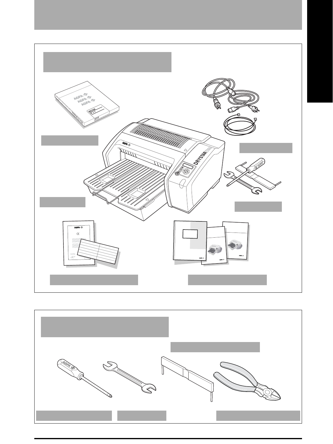
1Contents of the packages.
Drystar 5300 Set of tools
Set of cables
13 mm wrenchCrosshead screwdriver
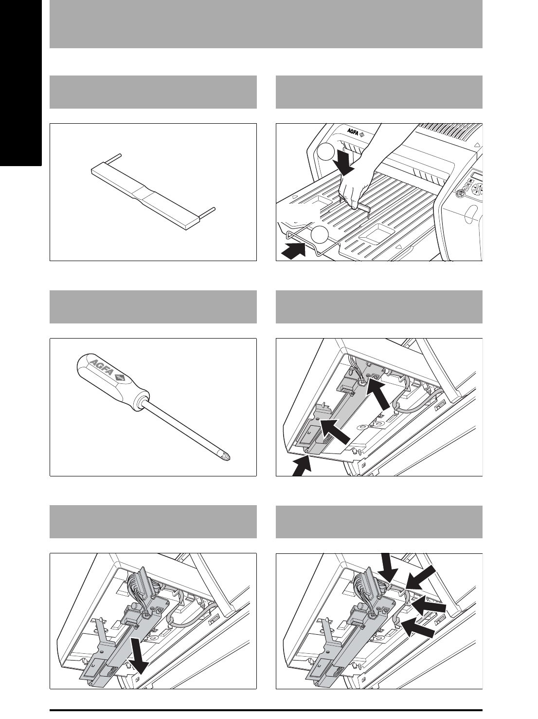
2Required tools (included).
Wire cutter (NOT included)
Output tray adjustment tool
A
Unpacking
4/16 2923B EN 20031206
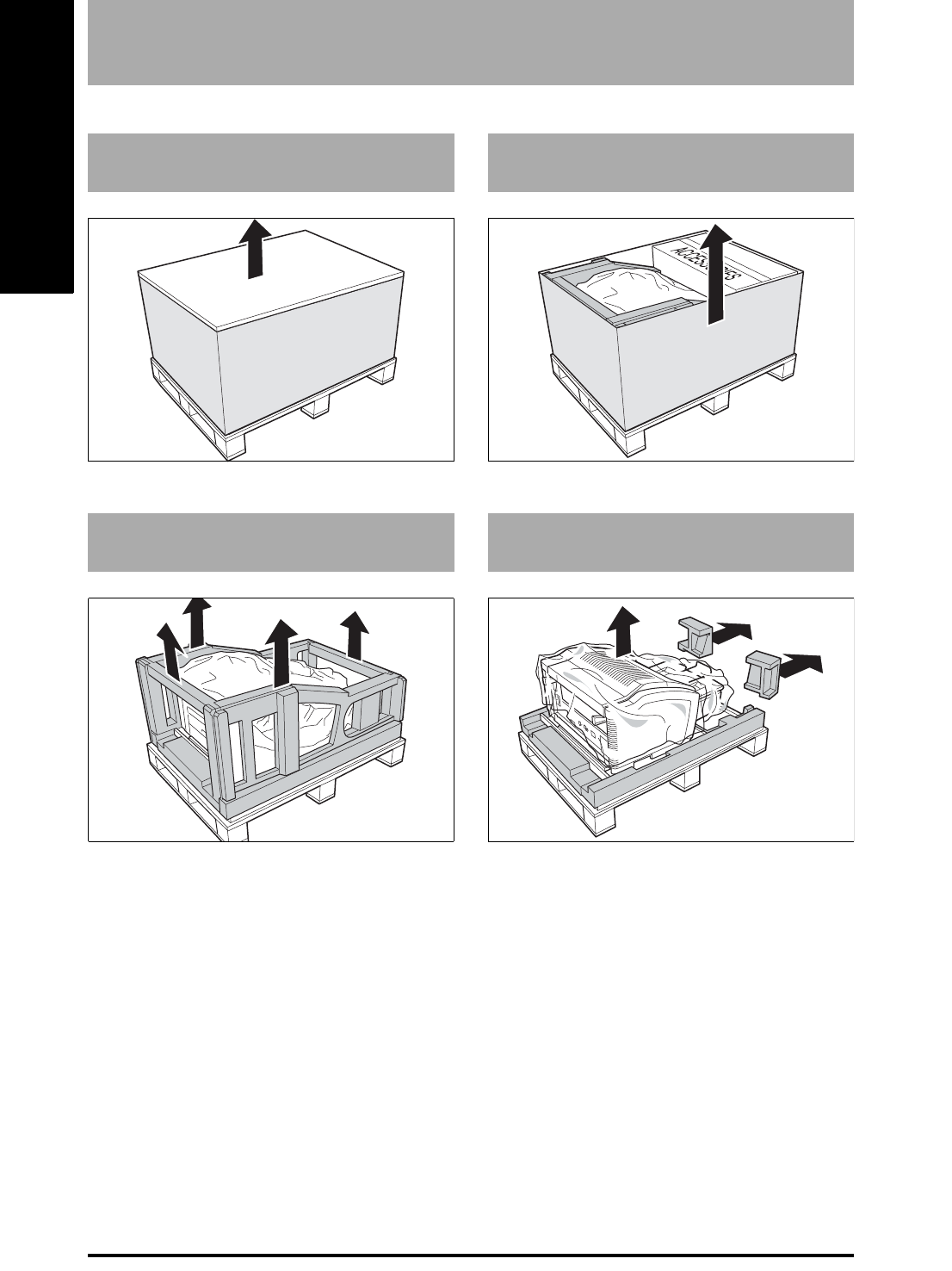
2Remove the packing materials
1Remove the wooden top plate.
3Remove the foam blocks.
2Remove the cardboard box.
4Remove the plastic bag.
Unpacking
A
5/16
2923B EN 20031206
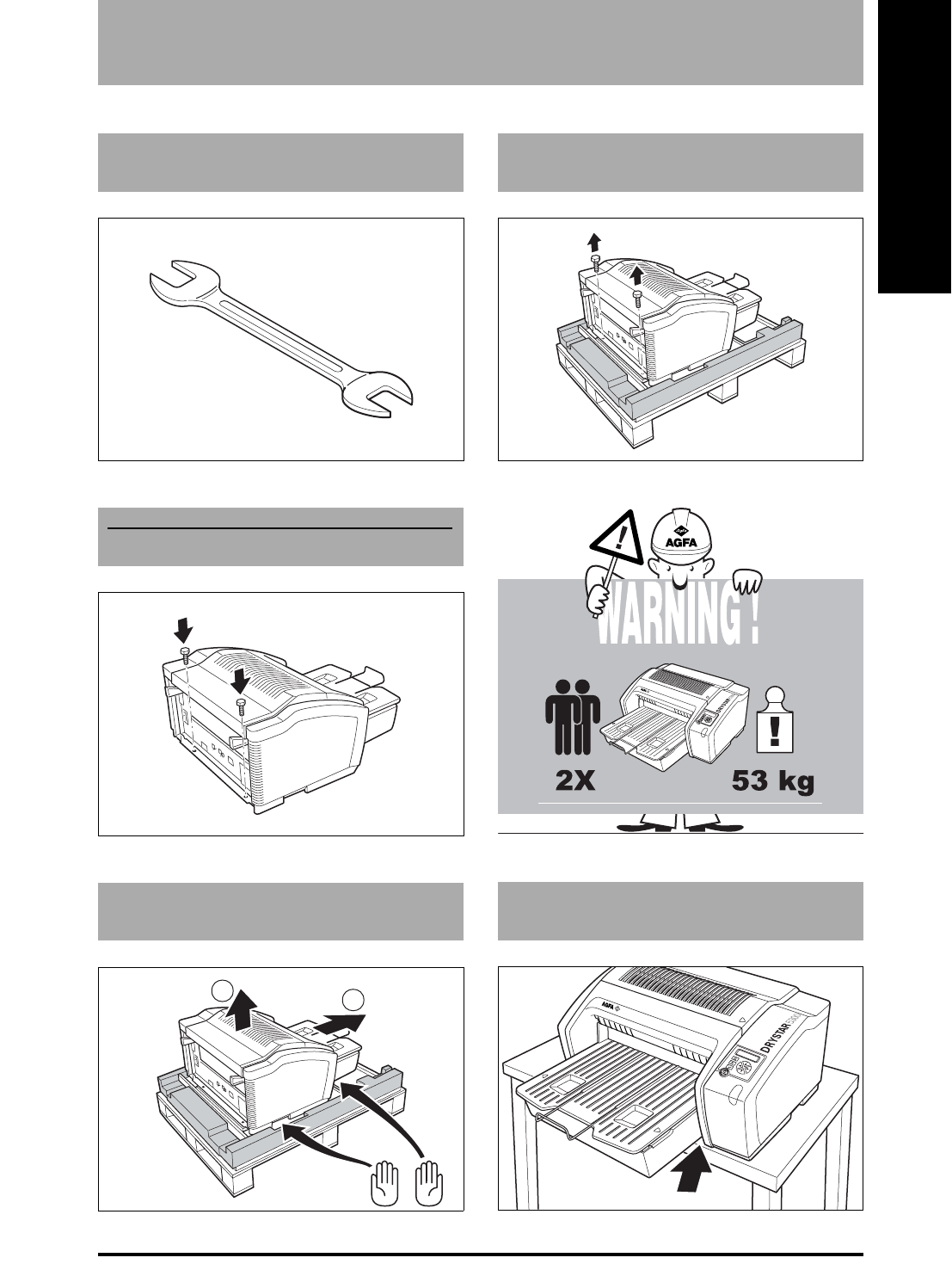
3Remove Drystar 5300 from pallet
1Take 13 mm wrench.
MOBILE or SEISMIC INSTALLATION ONLY:
reuse screws to fix printer at its location.
3Shift printer to the right [1] and lift it
from pallet [2].
1
2
2
Remove 2 screws.
4Put printer on a table.
Align with the table edge.
A
Unpacking
6/16 2923B EN 20031206
4Unpack the accessories
1Check all accessories.
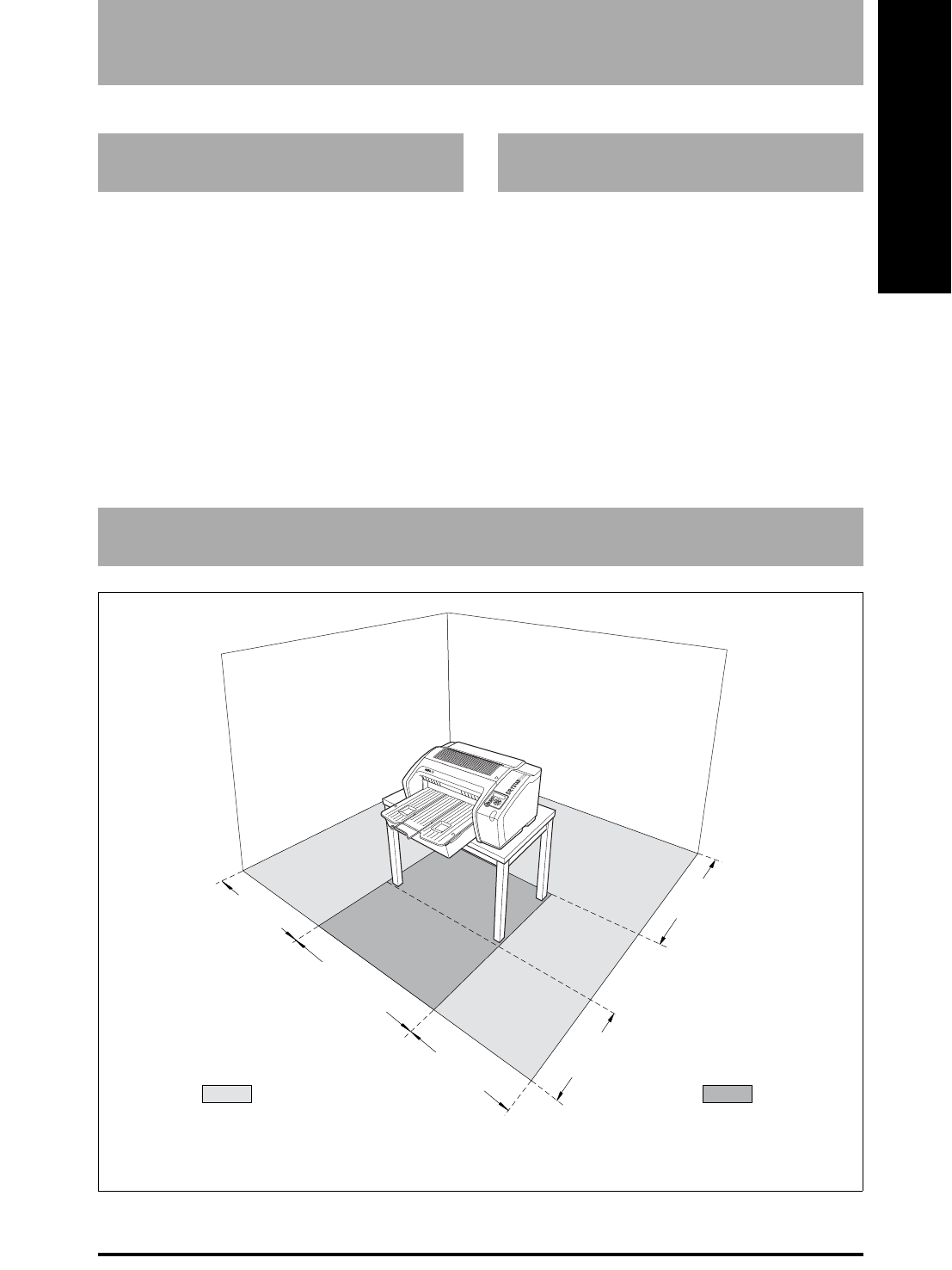
2Check all documents.
3Return the packing materials to a recycling service.
Dr
Drystar 5300
Reference manual
POWER
ystar5
300
User manual
POWER
Health Care
DECLARATION OF CONFORMITY
XXXXXX XXXX XXXXXX XXXXXX XXXX XXXXXX
XXXXXX XXXX XXXXXX XXXXXX XXXX XXXXXX
XXXXXX XXXX XXXXXX XXXXXX XXXX XXXXXX
XXXXXX XXXX XXXXXX
XXXXXX XXXX XXXXXX
XXXXXX XXXX XXXXXX
XXXXXX XXXX XXXXXX
XXXXXX XXXX XXXXXX XXXXXX XXXX XXXXXX
Refer to the Packing slip
for a complete list of
accessories.
Drystar5
300
User manual
Drystar 5300
Reference manual
Health Care
POWER
POWER
XXXXXX XXXX XXXXXXXXXXXX XXXX XXXXXX
XXXXXX XXXX XXXXXXXXXXXX XXXX XXXXXX
XXXXXX XXXX XXXXXXXXXXXX XXXX XXXXXX
XXXXXX XXXX XXXXXX
XXXXXX XXXX XXXXXX
XXXXXX XXXX XXXXXX
XXXXXX XXXX XXXXXX
XXXXXX XXXX XXXXXXXXXXXX XXXX XXXXXX
DECLARATION OF CONFORMITY
Refer to the Packing slip
for a complete list of
documents.
Wood
Paper
Plastic
Metals
Unpacking
A
7/16
2923B EN 20031206
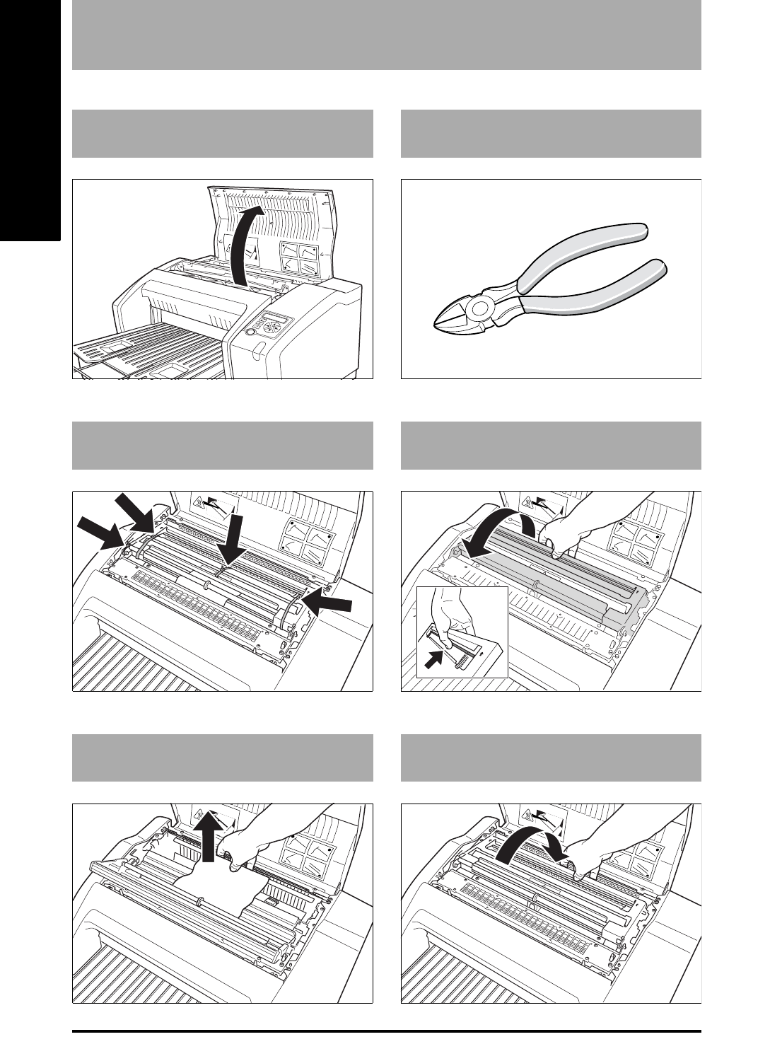
5Environment specifications
1Environment requirements.
3Space requirements.
◆
Ventilated room,
◆away from direct sunlight,
◆away from sources of dust, humidity,
heat and cold,
◆room temperature between 10°C (50°F)
and 30°C (86°F),
◆relative humidity between 10% and 80%
non-condensing.
600 mm
–24"
600 mm
–24"
600 mm
–24"
600 mm
–24"
800 mm
–32"
Space required for normal useSpace required for servicing and installation
2Power requirements.
The AC outlet must have either of following
s
pecifications:
◆100-120 V, 60 Hz, 16/15 A,
or
◆200-240 V, 50 Hz, 16/15 A.
B
Installation
8/16 2923B EN 20031206
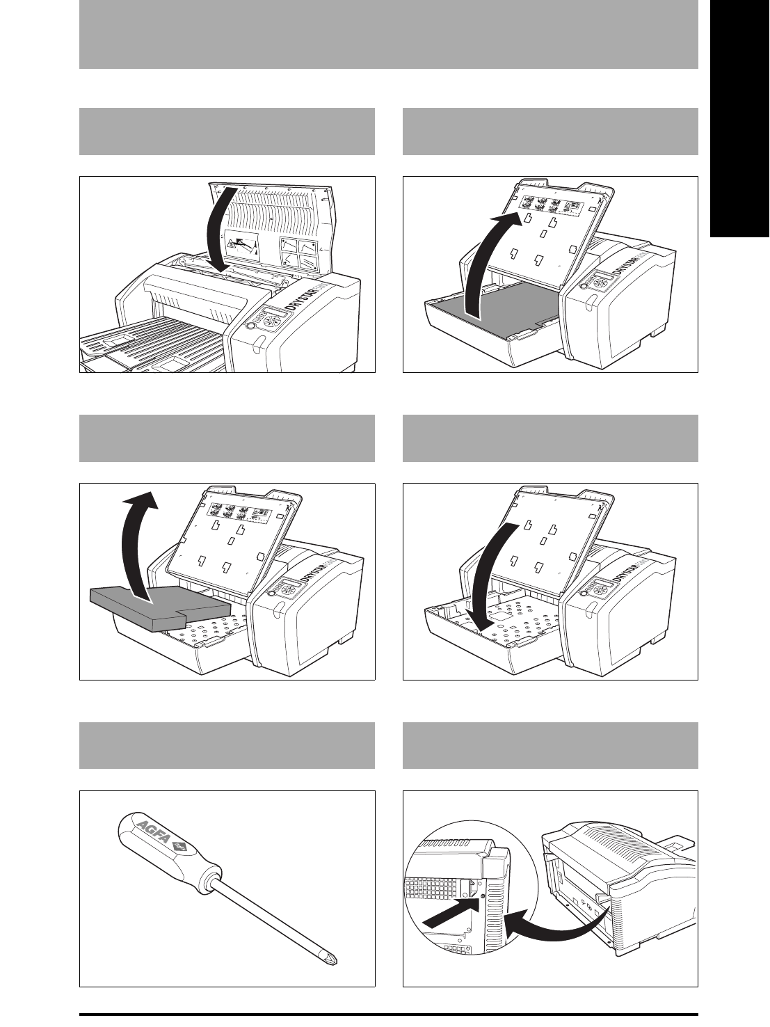
6Remove transport protections (1 of 2)
1Open top cover.
3Cut 4 red straps.
5Remove foam sheet.
2Take wire cutter.
4Open hold-down bracket.
6Close hold-down bracket.
Installation
B
9/16
2923B EN 20031206
7Remove transport protections (2 of 2)
7Close top cover.
9Remove foam block from input tray.
11 Take crosshead screwdriver.
1
3
2
4
5
6
XXXXXX XXXX XXXXXXXXXXXX XXXX XXXXXX
XXXXXX XXXX XXXXXXXXXXXX XXXX XXXXXX
XXXXXX XXXX XXXXXXXXXXXX XXXX XXXXXX
XXXXXX XXXX XXXXXX
XXXXXX XXXX XXXXXX
XXXXXX XXXX XXXXXX
XXXXXX XXXX XXXXXXXXXXXX XXXX XXXXXX
8Open input tray.
10 Close input tray.
12 Remove drum screw.
1
3
2
4
5
6
XXXXXX XXXX XXXXXX XXXXXX XXXX XXXXXX
XXXXXX XXXX XXXXXX XXXXXX XXXX XXXXXX
XXXXXX XXXX XXXXXXXXXXXX XXXX XXXXXX
XXXXXX XXXX XXXXXX
XXXXXX XXXX XXXXXX
XXXXXX XXXX XXXXXX
XXXXXX XXXX XXXXXXXXXXXX XXXX XXXXXX
1
3
2
4
5
6
XXXXXX XXXX XXXXXXXXXXXX XXXX XXXXXX
XXXXXX XXXX XXXXXX XXXXXX XXXX XXXXXX
XXXXXX XXXX XXXXXX XXXXXX XXXX XXXXXX
XXXXXX XXXX XXXXXX
XXXXXX XXXX XXXXXX
XXXXXX XXXX XXXXXX
XXXXXX XXXX XXXXXXXXXXXX XXXX XXXXXX
B
Installation
10/16 2923B EN 20031206
8Adjust Input block module - 11x14” (1 of 2)
1Take output tray adjustment tool.
3Take crosshead screwdriver.
5Lower film positioner unit.
2Push tool down into output tray holes
[1]. Push bracket until it clicks [2].
4Remove 3 screws.
6Loosen cable.
1
2
Click!
Installation
B
11/16
2923B EN 20031206
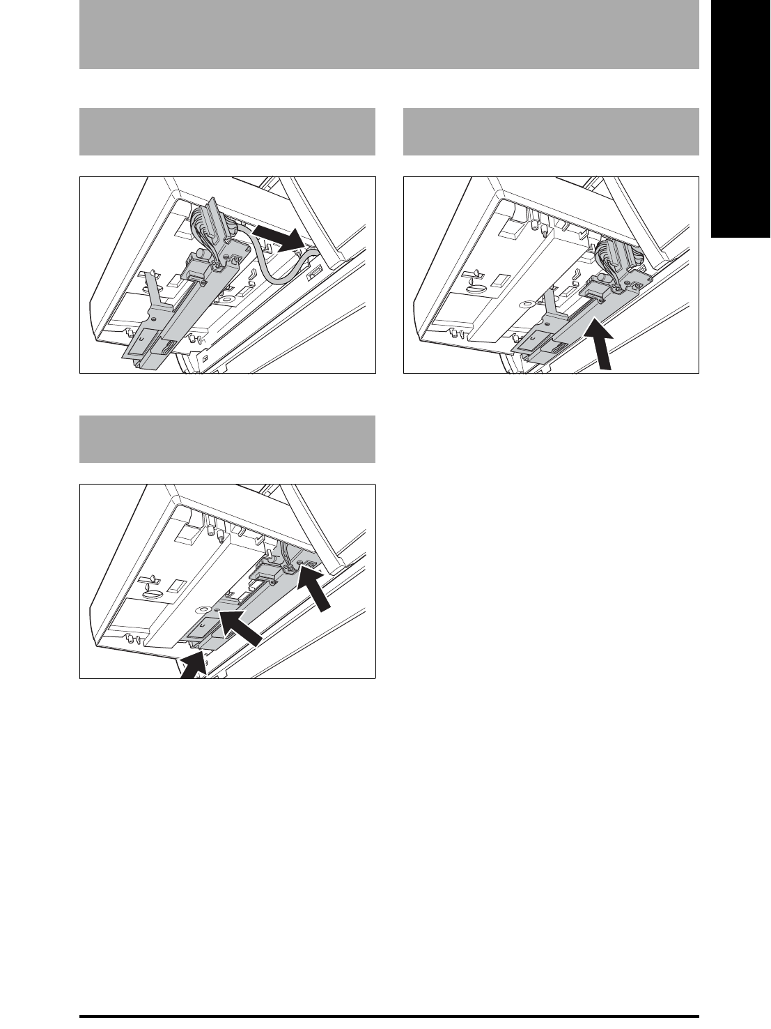
9Adjust Input block module - 11x14” (2 of 2)
7Push cable into printer housing.
9Remount 3 screws.
8Put and hold film positioner unit into
place.
B
Installation
12/16 2923B EN 20031206
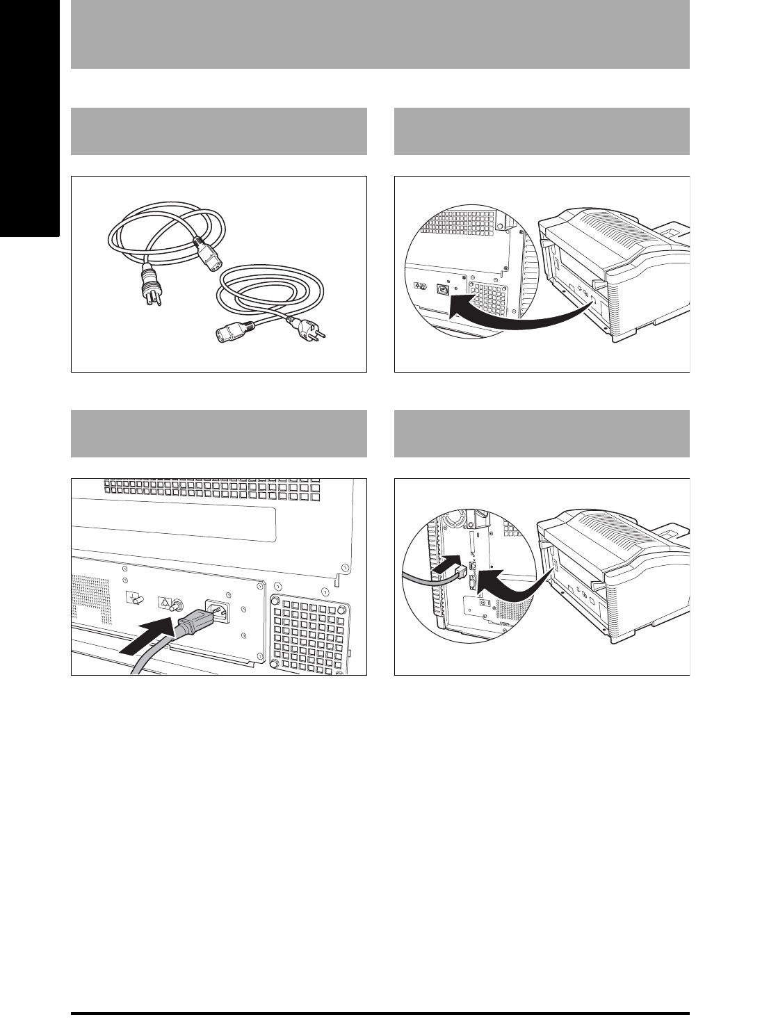
10 Connect the cables
2Locate the mains connector.
4Locate the network connector and
connect the network cable.
1Select the power cable.
3Connect the power cable.
B
Installation
13/16
2923B EN 20031206
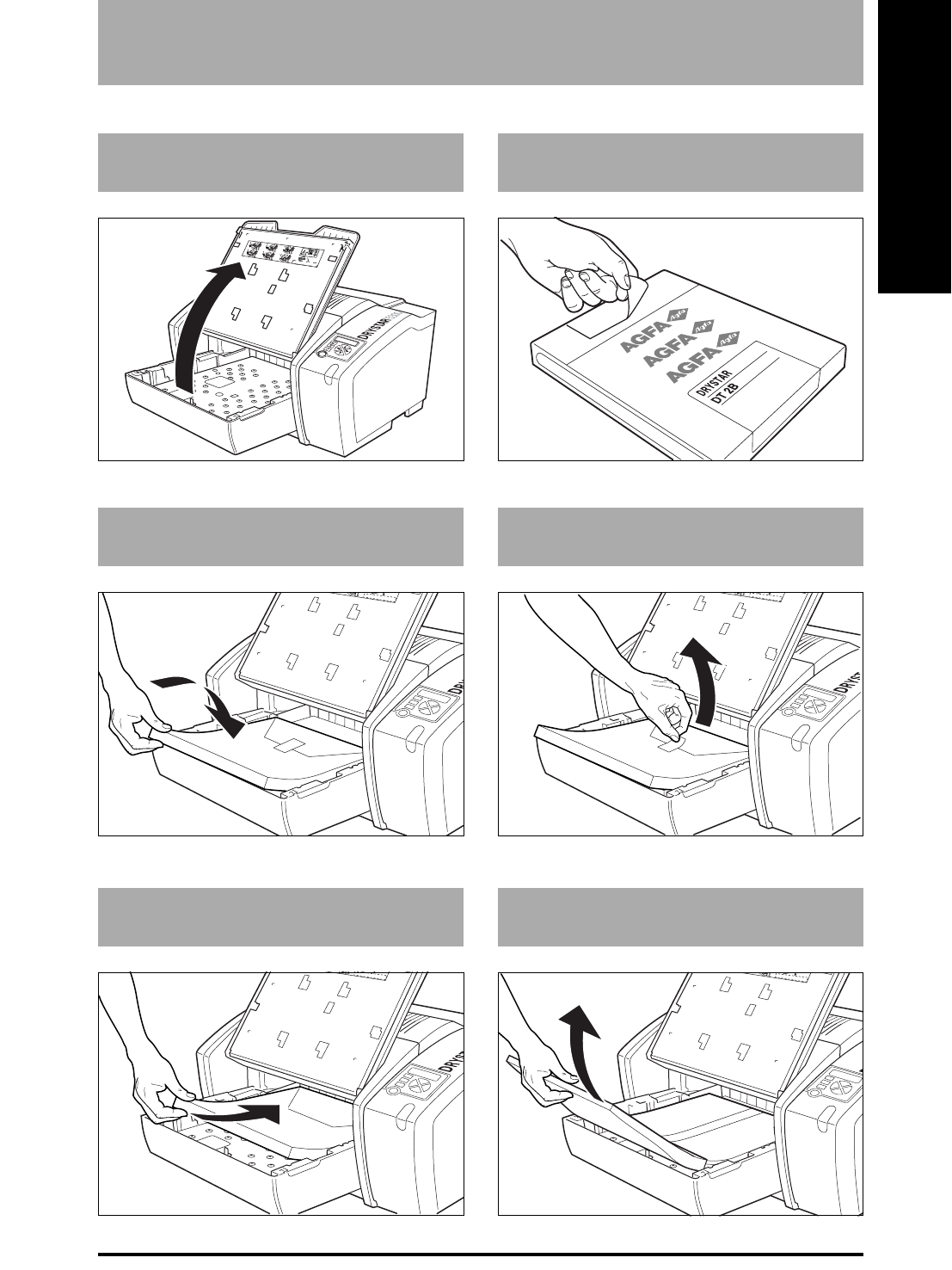
11 Load film in the input tray (1 of 2)
1Open input tray.
3Take film pack and slide it into the
input tray.
5Slide film pack further inside.
1
3
2
4
5
6
XXXXXX XXXX XXXXXXXXXXXX XXXX XXXXXX
XXXXXX XXXX XXXXXX XXXXXX XXXX XXXXXX
XXXXXX XXXX XXXXXXXXXXXX XXXX XXXXXX
XXXXXX XXXX XXXXXX
XXXXXX XXXX XXXXXX
XXXXXX XXXX XXXXXX
XXXXXX XXXX XXXXXXXXXXXX XXXX XXXXXX
XXXXXX
X
XXXXX XXXX X
XXXXXX XXXX XXXX
XX
XXXXXX XXXX XXXXXXXXXXXX XX
XX XXXXXX
2Open film box.
4Remove sticker.
6Remove plastic film bag.
XXXXXX X
XXXXXX XX
XX XXXXXX X
XXXXXX XXXX
XXXXXX
XXXX XXXXXX
XXXXXX XXXX XX
XXXX
XXXXXX XXXX XXXXXX
XXXXXX XXXX XXXXXX XXXXXX XXXX XXXXXX
Loading films
C
14/16 2923B EN 20031206
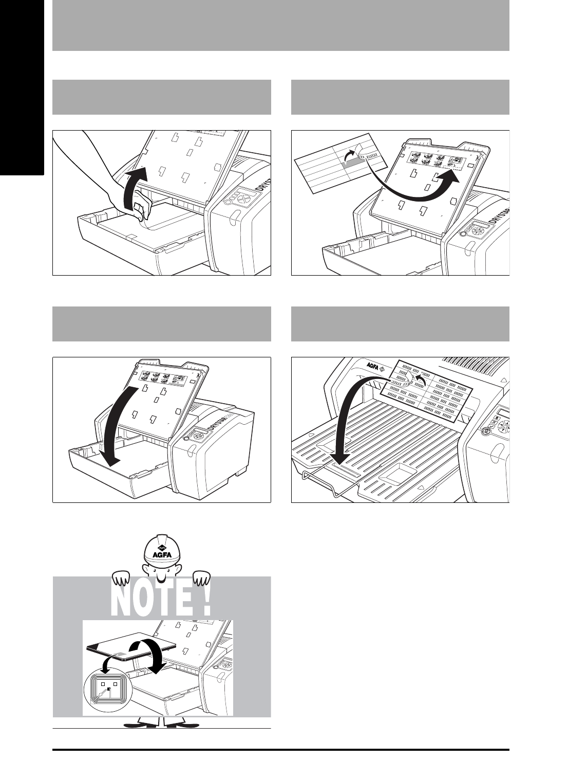
12 Load film in the input tray (2 of 2)
7Pull plastic tape from around films.
9Close input tray.
XXXXXX XX
XXXX
XX XXXX XXXXX
XXXXXX XXXX
XXXXXX
XXXXXX XXXX XXXXXX
XXXXXX XXXX XXXXXX XXXXXX XXXX XXXXXX
1
3
2
4
5
6
XXXXXX XXXX XXXXXX XXXXXX XXXX XXXXXX
XXXXXX XXXX XXXXXX XXXXXX XXXX XXXXXX
XXXXXX XXXX XXXXXX XXXXXX XXXX XXXXXX
XXXXXX XXXX XXXXXX
XXXXXX XXXX XXXXXX
XXXXXX XXXX XXXXXX
XXXXXX XXXX XXXXXX XXXXXX XXXX XXXXXX
8Place film type sticker.
10 Place film type sticker.
XXXXXX XXXX XXXXXX XXXXXX XXXX XXXXXX
XXXXXX XXXX XXXXXX XXXXXX XXXX XXXXXX
XXXXXX XXXX XXXXXX XXXXXX XXXX XXXXXX
XXXXXX XXXX XXXXXX
XXXXXX XXXX XXXXXX
XXXXXX XXXX XXXXXX
XXXXXX XXXX XXXXXX XXXXXX XXXX XXXXXX
1
3
2
4
5
6
XXXXXX XXXX XXXXXX XXXXXX XXXX XXXXXX
XXXXXX XXXX XXXXXXXXXXXX XXXX XXXXXX
XXXXXX XXXX XXXXXXXXXXXX XXXX XXXXXX
XXXXXX XXXX XXXXXX
XXXXXX XXXX XXXXXX
XXXXXX XXXX XXXXXX
XXXXXX XXXX XXXXXXXXXXXX XXXX XXXXXX
C
Loading films
15/16
2923B EN 20031206
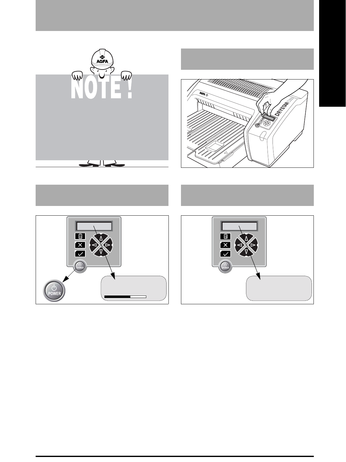
13 Startup Drystar 5300
2Press the POWER button.
The film delivered with the printer is
intended for test purposes only.
Please WAIT
Self test
proceeding 62%
1Remove the display protection foil.
3Wait until READY.
READY
D
Startup
16/16 2923B EN 20031206
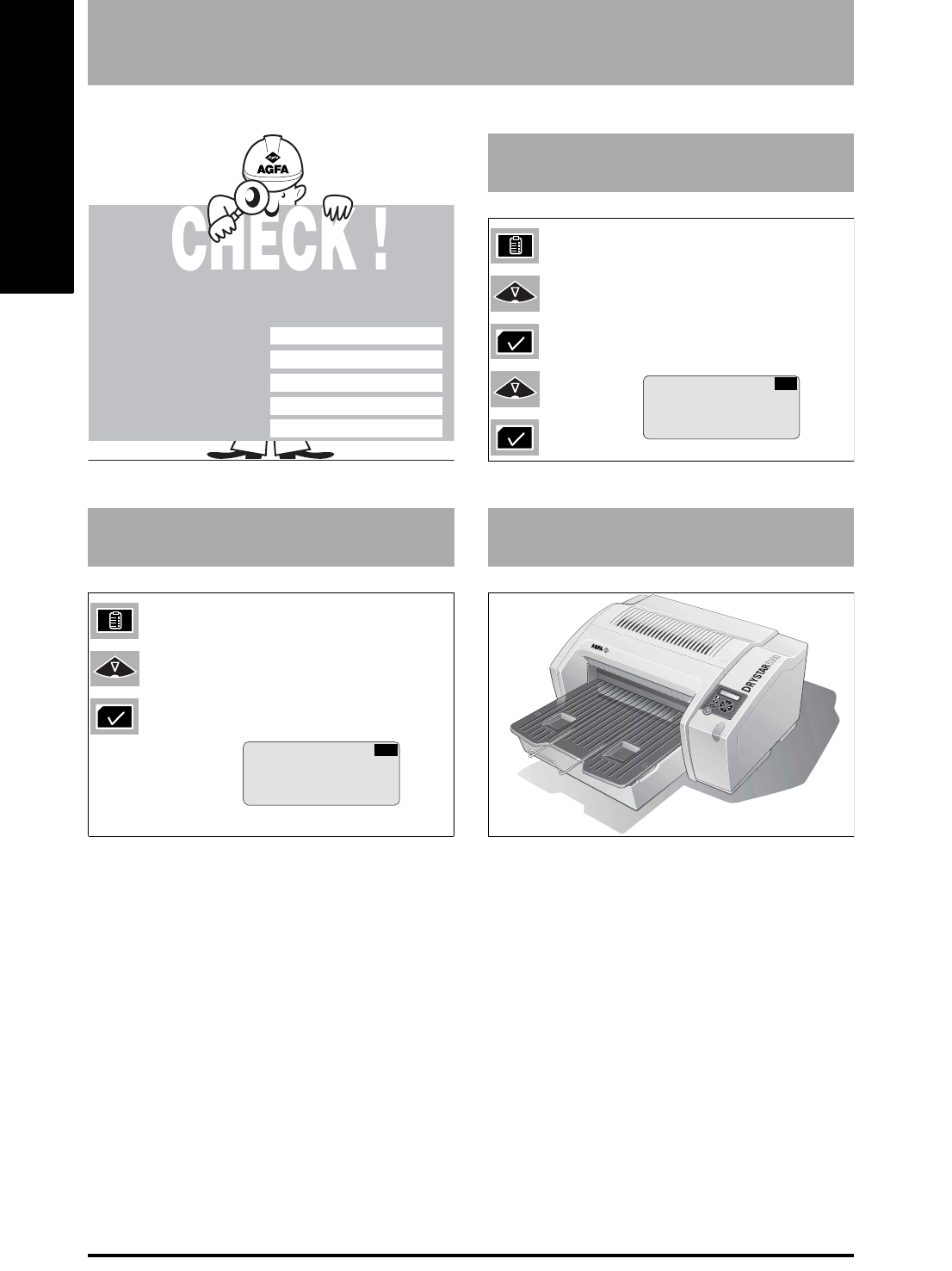
14 Configure network settings
2Select and initiate film calibration.
Ask your network manager
the following information:
Printer IP address:
Netmask:
Router IP address:
Printer AE_Title:
Service Host IP address:
1. Press the Key-operator key.
2. Press the Down key five times.
3. Press the Confirm key twice.
4. Follow the instructions
(see Reference manual).
1x
5x
2x
SELECT
CALIBRATION
1 Film calibration
2 Therm. Head clean.
CA
1Select and initiate the printer
installation wizard.
3Your Drystar 5300 is ready for use!
1. Press the Key-operator key.
2. Press the Down key eight times.
3. Press the Confirm key.
4. Press the Down key.
5. Press the Confirm key.
6. Follow the instructions
(see Reference manual).
1x
8x
1x
1x
1x
1 Installation
from CF card
2 Printer
installation
IN
POWER
E
Network