Agfa NV 5366A Drystar 5302 /xxx Medical tabletop printer User Manual Print Composer Module for CR Quality System 3 0
Agfa Gevaert N V Drystar 5302 /xxx Medical tabletop printer Print Composer Module for CR Quality System 3 0
Agfa NV >
manual
Drystar 5302
User manual

22831A EN 20041201
DRYSTAR 5302 USER MANUAL
This product is registered in China under the registration number:
For more information on Agfa products and Agfa HealthCare products, please visit www.agfa.com, your Point
of Knowledge.
© Agfa-Gevaert N.V. 2004.
No parts of this document may be reproduced, copied, adapted or transmitted in any form or by any means
without the written permission of Agfa-Gevaert N.V.
Agfa-Gevaert N.V. makes no warranties or representation, expressed or implied, with respect to the accuracy,
completeness or usefulness of the information contained in this document and specifically disclaims warran-
ties of suitability for any particular purpose. Agfa-Gevaert N.V. shall under no circumstances be liable for any
damage arising from the use or inability to use any information, apparatus, method or process disclosed in this
document.
Agfa-Gevaert N.V. reserves the right to make changes to this document without prior notice.
Agfa-Gevaert N.V., Septestraat 27, B-2640 Mortsel, Belgium.
Drystar 5302 is a trademark of Agfa-Gevaert N.V., Belgium.
Agfa and Agfa-Rhombus are trademarks of Agfa-Gevaert AG, Germany.
SFDA label DS5302
To Be defined

3
2831A EN 20041201
DRYSTAR 5302 USER MANUAL
Table of contents
Chapter 1: Introducing the Drystar 5302 ..................................................5
Drystar 5302 features.....................................................................................6
Safety precautions ..........................................................................................9
Security precautions.....................................................................................12
Safety compliance.........................................................................................13
Privacy and security .....................................................................................15
Operating modes ..........................................................................................17
Control modes (local and remote) ...............................................................19
The user interface.........................................................................................20
Switching on the Drystar 5302.....................................................................30
Switching off the Drystar 5302 ....................................................................32
Chapter 2: Basic operation (Operator mode) ..........................................33
Overview of operator functions ...................................................................34
Managing the print queue ............................................................................35
About Drystar 5302 consumables ................................................................37
Loading films ................................................................................................38
Chapter 3: Advanced operation (key-operator mode) ..........................45
Overview of key-operator functions.............................................................46
Quality Control .............................................................................................47
Preventive maintenance schedule ................................................................59
Cleaning the exterior....................................................................................60
Cleaning the print head ................................................................................61
Troubleshooting checklist ............................................................................65
Appendix A: Equipment information sheet..............................................67
Specifications ...............................................................................................68
Viewing the System info area on a film........................................................72
Options and accessories ...............................................................................73
Connectivity..................................................................................................74
Appendix B: Quality Control Charts ..........................................................75

42831A EN 20041201
DRYSTAR 5302 USER MANUAL

Introducing the
Drystar 5302
This chapter introduces the Drystar 5302 to the user and
draws attention to important safety precautions.
!Drystar 5302 features
!Safety precautions
!Security precautions
!Safety compliance
!Privacy and security
!Operating modes
!Control modes (local and remote)
!The user interface
!Switching on the Drystar 5302
!Switching off the Drystar 5302
Chapter 1

62831A EN 20041201Introducing the Drystar 5302
DRYSTAR 5302 USER MANUAL
Drystar 5302 features
The Drystar 5302 is a dry digital tabletop printer for producing medical
diagnostic images. It can print multiple formats (8x10” up to 14x17”) of blue-
based and clear-based film and offers crisp, dense grayscale images.
The Drystar 5302 offers the following features:
"Dry technology for printing diagnostic quality hardcopies in full daylight offers
important advantages: no chemistry, no wet processing, simple cleaning proce-
dures, no time-consuming adjustments, no darkroom and no chemical disposal
costs. The consumables can be loaded in full daylight.
"With its compact design, the Drystar 5302 needs little work space and allows
easy customer access. Maintenance and service activities are reduced to a mini-
mum.
"The direct thermal printing system provides grayscale images with high quality:
320 pixels per inch resolution, each pixel with 12 bit contrast resolution and an
optical density ranging from 0.2 up to 3.1 (measured with an X-Rite 310 densit-
ometer).
"Multiple film formats (8x10”, 10x12”, 11x14”, 14x14” and 14x17”) can be used.
Any combination of two film formats can be used “online”. Both input trays can
be adjusted for all film formats.
"The input trays of the Drystar 5302 are equipped with an RF-tag reader, which
automatically traces the films used in the printer and protects the printer when
detecting non-identified media.
"Number of input trays.
The Drystar 5302 is equipped with 2 input trays. Both input trays can use multiple formats
(8x10” up to 14x17”).
The Drystar 5302 is a Dicom-only network printer.
7
2831A EN 20041201 Introducing the Drystar 5302
DRYSTAR 5302 USER MANUAL
"Number of output trays.
The Drystar 5302 is equipped with 1 output tray, which is suitable for the
multiple formats without any adjustment.
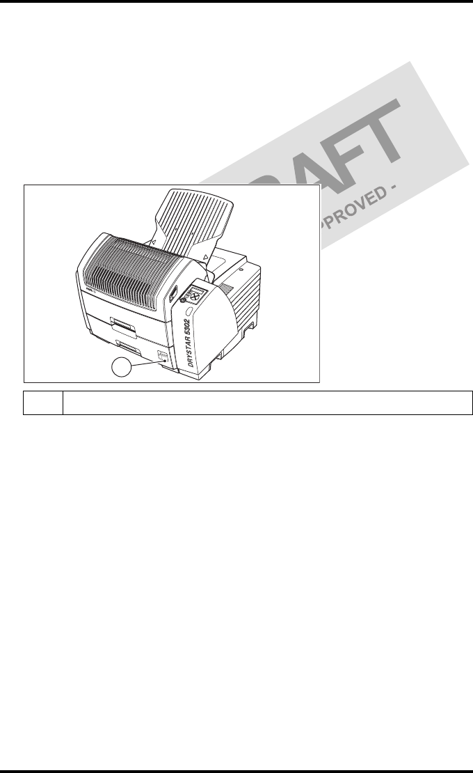
"Integrated A#sharp technology
A#sharp is a technology that enhances image sharpness for the Drystar 5302.
An A#sharp label on the lower tray shows that the imager has been upgraded
with this technology.
Network features
"The modular design offers optimal application functionality for your specific
networking requirements.
In a network configuration, the Drystar 5302 is fully compatible with Agfa’s
diagnostic imaging systems, including the ADC Compact and ADC Quality
System software, the Paxport and the entire line of Impax Review Systems,
Storage Stations and Transmitting Stations. For more information, contact
your Agfa representative.
"The functionality of the Drystar 5302 is completely controlled via the network.
"You can control the working of the Drystar 5302 via the local keypad or via a
remote PC with a functioning web browser.
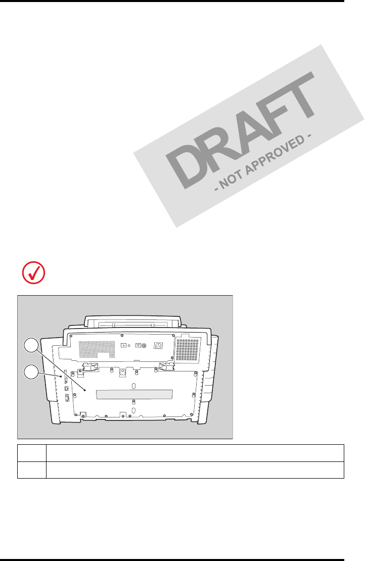
1A#Sharp label
1

82831A EN 20041201Introducing the Drystar 5302
DRYSTAR 5302 USER MANUAL
Customizable features
"Consumables.
The Drystar 5302 can handle Drystar DT 2B and Drystar DT 2C consumables,
both in multiple formats (8x10” up to 14x17”).
Software license information
"The Drystar 5302 uses software developed by the Apache Software Foundation
(http://www.apache.org/licenses/LICENSE).
9
2831A EN 20041201 Introducing the Drystar 5302
DRYSTAR 5302 USER MANUAL
Safety precautions
When operating or maintaining the Drystar 5302, always observe the
following safety guidelines:
•Have electrical or mechanical defects repaired by qualified personnel only!
•Do not override or disconnect the integrated safety features.
•Ventilation openings should not be covered.
•Always switch off the Drystar 5302 and disconnect the power cord from
the outlet before carrying out any maintenance work.
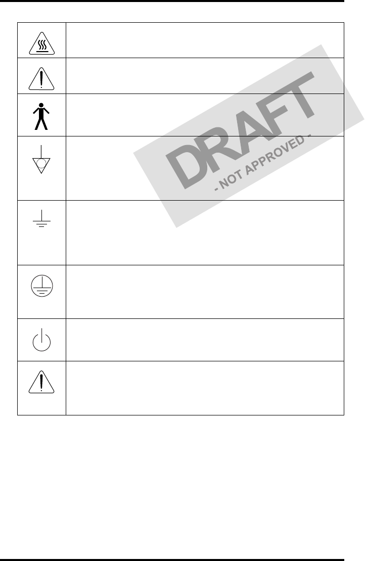
Always take into account the markings provided on the inside and outside of
the printer. A brief overview of these markings and their meaning is given
below.
The Drystar 5302 must only be operated according to its specifications and its
intended use. Any operation not corresponding to the specifications or intended use
may result in hazards, which in turn may lead to serious injuries or fatal accidents
(for example electric shocks). AGFA will not assume any liability whatsoever in
these cases.
All images created using any image technology can show artifacts which could be
mixed up with diagnostic relevant information. If there is any doubt that the
diagnostic information could not be absolutely true, additional investigations must
be performed to get a clear diagnostic.
Film jam removal or cleaning the printer thermal head can be done without
switching the power off. Nevertheless, care should be taken and the following
instructions should be respected:
Safety warning, indicating that the Drystar 5302 manuals should be
consulted before making any connections to other equipment. The
use of accessory equipment not complying with the equivalent safety
requirements of this printer may lead to a reduced level of safety of
the resulting system. Consideration relating to the choice of
accessory equipment shall include:
• Use of the accessory equipment in the patient vicinity,
• Evidence that the safety certification of the accessory equipment
has been performed in accordance with the appropriate IEC 601-1
and IEC 601-1-2 harmonized national standard.
In addition all configurations must comply with the medical
electrical systems standard IEC 601-1-2. The party that makes the
connections acts as system configurator and is responsible for
complying with the systems standard.
If required contact your local service organization.
10 2831A EN 20041201Introducing the Drystar 5302
DRYSTAR 5302 USER MANUAL
Transport after installation
Before moving the printer, always switch off the machine. The Drystar 5302
should be transported by 3 persons or if not possible with 2. Refer to ‘Remove
Drystar 5302 from pallet’ on page 5 of the Installation manual. When doing
this, the stability and the structure of the table top have to be taken into
account. The printer should not be placed on a soft surface, since this might
prevent appropriate ventilation and cause overheating. The printer must only
be transported with all covers closed. The appliance may not be transported
Caution hot:
Keep hands clear from the thermal print head.
In order to reduce the risk of electric shock, do not remove any
covers.
Type B equipment:
Indicates that the Drystar 5302 complies with the limits for type B
equipment.
Supplementary protective earth connector:
Provides a connection between the Drystar 5302 and the potential
equalization busbar of the electrical system as found in medical
environments. This plug should never be unplugged before the
power is turned off and the power plug has been removed.
Intergrounding connector:
Provides a connection between the printer and other equipment
which might exhibit minor ground potential differences. These
differences may degrade the quality of communication between
different equipment. Never remove connections to this terminal.
Protective earth (ground):
Provides a connection between the printer and the protective earth
of the mains. Do not remove this connection, because this will have a
negative influence on the leakage current.
Power button:
Note that the power cord has to be disconnected from the wall outlet
in order to disconnect the unit entirely from the mains.
Precautions for use in USA only:
Make sure that the circuit is single-phase center-tapped, if the printer
is connected to a 240 V/60 Hz source instead of a 120 V/60 Hz
source.

11
2831A EN 20041201 Introducing the Drystar 5302
DRYSTAR 5302 USER MANUAL
continuously from one location to the other. Do not lift the printer by the
output tray.
Waste disposal and environmental regulations
In most countries Drystar film is considered industrial waste and
consequently it is not allowed to be disposed as household waste. Please
consult your local waste disposal regulations. Agfa recommends having waste
Drystar film collected by a licensed company.
After its life span, do not dispose of the Drystar 5302 without consideration of
local waste disposal regulations. Please consult your local service
organization.

12 2831A EN 20041201Introducing the Drystar 5302
DRYSTAR 5302 USER MANUAL
Security precautions
U.S. Law restricts this device to sale to or on the order of a licensed physician.
Printed images should be treated as patient records and should only be
viewed by authorized personnel.
If the power to the printer is unexpectedly interrupted, ensure that
unprinted images are not deleted from the modality prior to printing. To
avoid loss of images in such conditions, a UPS (Uninterruptable Power
Supply) needs to be supplied to the printer.

13
2831A EN 20041201 Introducing the Drystar 5302
DRYSTAR 5302 USER MANUAL
Safety compliance
EMC issues
•USA: This equipment has been tested and found to comply with the limits
for a class A digital device, pursuant to part 15 of the FCC rules. These
limits are designed to provide reasonable protection against harmful
interference when the equipment is operated in a commercial
environment. This equipment generates, uses and can radiate radio
frequency energy and, if not installed and used in accordance with the
Drystar 5302 Reference manual, may cause harmful interference to radio
communications. Operation of this equipment in a residential area is likely
to cause harmful interference, in which case the user will be required to
correct the interference at its own expense.
If required, contact your local service organization.
•Canada: This class A digital apparatus meets all requirements of the
Canadian Interference-Causing Equipment Regulations.
•EC: This is a class A product. In a domestic environment this product may
cause radio interference in which case the user may be required to take
adequate measures.
Compliances
The Drystar 5302 has been tested and found to comply with the following
international standards and regulations:
•the Medical Devices Directive 93/42/EEC
•CFR Part 21
Safety standards
•IEC 60601-1 + A1 + A2
•EN 60601-1 + A1 + A2
•UL 60601-1
•CSA 22.2 No. 601.1-M90
•GB4943-2001 (for CCC-Mark)
14 2831A EN 20041201Introducing the Drystar 5302
DRYSTAR 5302 USER MANUAL
Radio-interference regulations (interference suppression)
•FCC Rules 47 CFR part 15 subpart B
•IEC 60601-1-2
•CISPR 11, class A
•CISPR 22, class A
•IEC 61000-4-3
•IEC 61000-4-4
•IEC 61000-4-5
•IEC 61000-4-6
•IEC 61000-3-2
•IEC 61000-3-3
•IEC 61000-4-11
•ETSI 300330
•GB9254-1998(Class A) (for CCC-Mark)
•GB17625.1-2003 (for CCC-Mark)
Labels
The Drystar 5302 carries the CE, TÜV, cULus and CCC labels.
1CCC label
2CE, TÜV and cULus label
2
1

15
2831A EN 20041201 Introducing the Drystar 5302
DRYSTAR 5302 USER MANUAL
Privacy and security
Within the healthcare industry, several standardization efforts are ongoing as
a response to Privacy and Security legislation and regulations. The purpose of
this standardization for hospitals and vendors is to enable information
sharing, interoperability and to support the workflow of hospitals in a
multiple vendor environment.
In order to allow hospitals to comply with HIPAA regulations (Health
Insurance Portability and Accountability Act) and to meet the IHE standards
(Integrated Healthcare Enterprise) some security features are included in the
user interface of the Drystar 5302 (available via the web pages only: under
‘Security tools’. Refer to Chapter 4, ‘Controlling the Drystar 5302 via a remote
PC (with browser)’ of the Drystar 5302 Reference manual):
•User authentication. The administrator can configure different user
accounts. Each account consists of a user name and a password.
•Audit logging. This implies logging to a central log server of specific
Drystar 5302 ‘actions’, e.g. startup/shutdown, user authentication
(failures), received print job ID information, etc.
•Node authentication, using certificates. Working with SSL (Secure Sockets
Layer) allows secure communications over an insecure network. SSL is the
security layer on top of TCP/IP.
The first two functions are available when access to the Administrator is
granted (i.e. when the Administrator password has been correctly entered).
To activate the SSL, please contact your Agfa representative.
Node authentication, certificates and Certification Authority
Each device - connected to a network - will receive a unique identifier: the
X.509 certificate, a digital passport. Any device on the network is only
allowed to communicate with another node of which it is holding the
certificate in a ‘communication allowed’ table.
A Certification Authority (CA) is responsible for creating a certificate. The CA
can be the hospital, Agfa or a third party.

16 2831A EN 20041201Introducing the Drystar 5302
DRYSTAR 5302 USER MANUAL
This CA distributes the certificate to the hospital security responsible or
service technician, who for his part:
•Imports the device certificate, created by the CA.
•Imports the certificates of all peer devices with which communication is
authorized, i.e. creates the list of ‘communication allowed’ device
certificates.

17
2831A EN 20041201 Introducing the Drystar 5302
DRYSTAR 5302 USER MANUAL
Operating modes
The Drystar 5302 can be operated in five modes: Operator mode, Key-
operator mode, Service mode, Specialist mode and Administrator mode.
Operator mode
The Operator mode groups all basic functions that are intended for
radiographers without special technical skills:
•Producing diagnostic usable hardcopies;
•Loading consumables;
•Ensuring normal operation of the printer.
All functions of the Operator mode are described in both User and Reference
manuals. Refer to Chapter 2, ‘Basic operation (Operator mode)’.
Key-operator mode
The Key-operator mode groups advanced functions that are intended for
technically skilled operators such as X-ray operators, network managers and
service and hospital technicians.
The Key-operator mode is menu-driven. The Key-operator functions are
described in the Drystar 5302 Reference manual only. Refer to Chapter 3,
‘Advanced operation (Key-operator mode)’.
Service mode
The Service mode functions are reserved for trained Service personnel. The
Service mode is password protected and is only accessible by browser via a
remote PC.
Specialist mode
The specialist mode functions are reserved for trained service personnel of
the Agfa Customer Support Center. The specialist mode is password protected
and is only accessible by browser via a remote PC.

18 2831A EN 20041201Introducing the Drystar 5302
DRYSTAR 5302 USER MANUAL
Administrator mode (also known as Security)
The Administrator mode functions are reserved for the System Administrator.
The Administrator mode is password protected and is only accessible by
browser via a remote PC.

19
2831A EN 20041201 Introducing the Drystar 5302
DRYSTAR 5302 USER MANUAL
Control modes (local and remote)
You can control the working of the Drystar 5302 via the local keypad or via a
network remote PC.
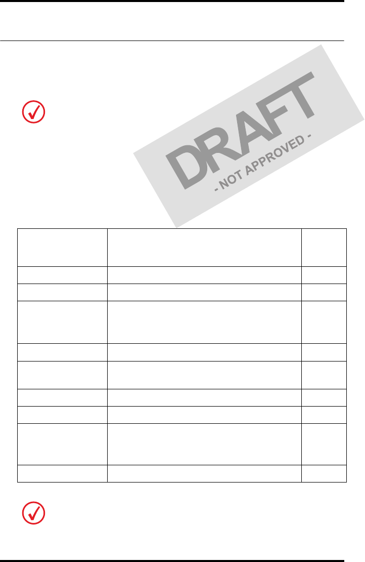
The table below gives an overview of the operating modes you can access
locally and/or via the remote PC.
The manual describes the controlling of the Drystar 5302 via the local
keypad. The menus for controlling the Drystar 5302 via a remote PC are
structured in the same way and sometimes they offer even more possibilities.
Refer to Chapter 4, ‘Controlling the Drystar 5302 via a remote PC (with
browser)’ of the Drystar 5302 Reference manual.
Local Password
protected Remote Password
protected
Operator mode No ––– –––
Key-operator mode No Key-operator mode Yes
––– ––– Service mode Yes
––– ––– Specialist mode Yes
––– ––– Administrator Yes
20 2831A EN 20041201Introducing the Drystar 5302
DRYSTAR 5302 USER MANUAL
The user interface
The Drystar 5302 interfaces with the user via the following controls:
•Power/Reset button;
•a keypad and a display;
•a status indicator LED;
•audio signals.
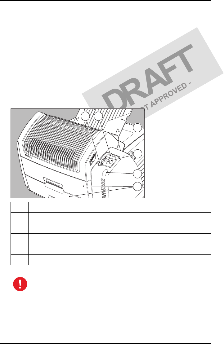
Overview of user interface controls
1Power/Reset button
2Display
3Keypad
4Status indicator LED
5Film input trays
6Film output tray
Never try to open the printer when the Drystar 5302 is printing a film.
Always follow the instructions on the display!
1 2
3
4
6
5
21
2831A EN 20041201 Introducing the Drystar 5302
DRYSTAR 5302 USER MANUAL
The status indicator LED
On the right side of the display, an LED indicates the status of the
Drystar 5302.
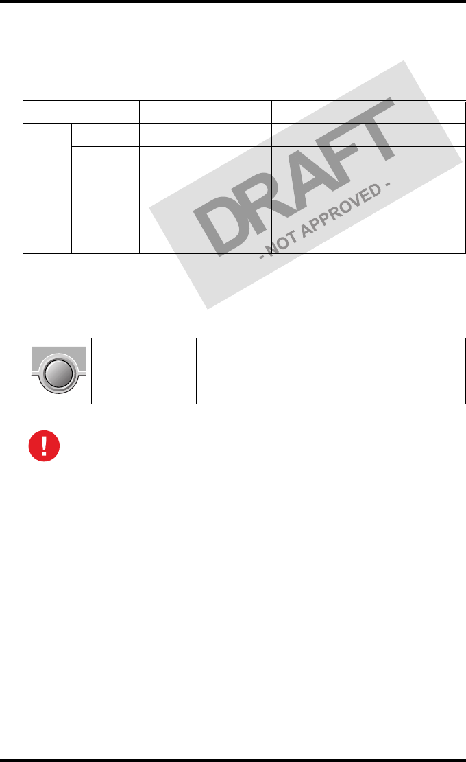
The control buttons
One control button has been provided:
Color / Light Status Action
Green
Constant Ready (stand-by) Proceed
Blinking Busy or in key-
operator mode Wait
Red
Blinking Warning status Check the display for messages.
Refer to ‘Checking the status
indicator LED’ on page 157 of the
Drystar 5302 Reference manual.
Constant Error status
Power/Reset
button
• To power on or off the printer.
• To reset the printer.
Do NOT press the Power/Reset button without first following the
procedure to stop printing when the Drystar 5302 is printing a film. Refer
to ‘Switching off the Drystar 5302’ on page 32.
22 2831A EN 20041201Introducing the Drystar 5302
DRYSTAR 5302 USER MANUAL
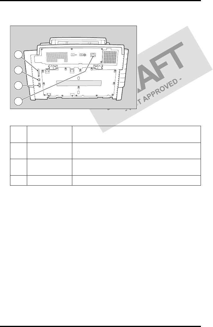
Rear panel
At the rear side of the printer, one slot and three connectors are available:
1CF-card slot • To insert an external CF-card for software
installation, backup, etc.
2Network
connector • To connect to the hospital network.
3Input/output
connector
• To connect a terminal PC (used by the Service
engineer).
4Power connector • To connect the printer power cord.
4
3
2
1
23
2831A EN 20041201 Introducing the Drystar 5302
DRYSTAR 5302 USER MANUAL
Working with Compact flash cards (CF-card)
The Drystar 5302 is equipped with an external CF-card slot.
A CF-card has the following physical characteristics:
•a flat surface on one side (there is also often a label present),
•a small rim on the other side,
•connector holes on the opposite side of the rim side.
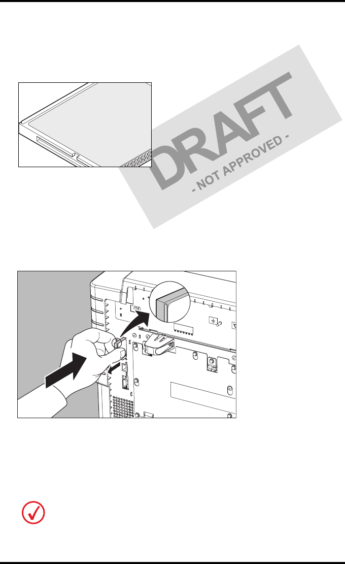
Inserting a CF-card
To insert a CF-card in the Drystar 5302 (the slot is located at the rear side):
1Hold the CF-card vertically with the connector holes in front of the slot and with
the flat surface pointing to the left.
2Insert the CF-card gently into the slot and push it until the unlocking lever
underneath the slot comes out.
If you cannot push the CF-card completely into its position, this means that you
have to turn it 180 degrees (while keeping the connector holes faced to the slot).
1
2
24 2831A EN 20041201Introducing the Drystar 5302
DRYSTAR 5302 USER MANUAL
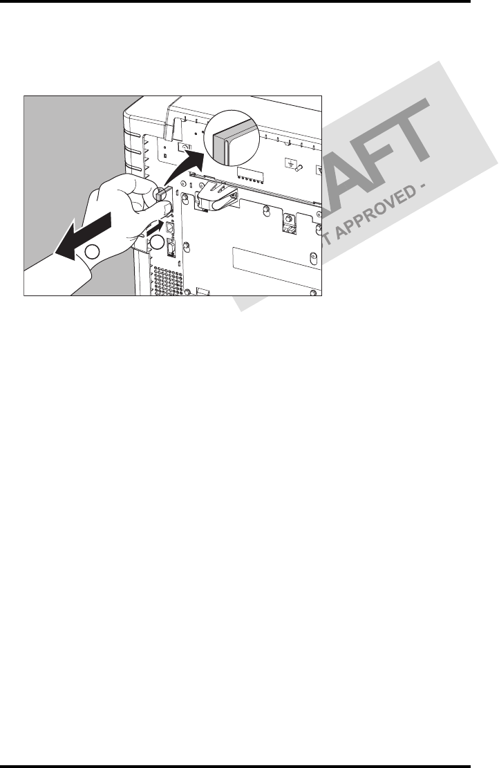
Removing a CF-card
To remove a CF-card from the Drystar 5302 slot:
1Push the unlocking lever underneath the CF-card slot.
The CF-card is pushed slightly outward.
2Remove the CF-card gently from the slot.
1
2

25
2831A EN 20041201 Introducing the Drystar 5302
DRYSTAR 5302 USER MANUAL
Audio signals
The Drystar 5302 gives status information via beeps. The length of the beep
indicates the response of the system to a key command.
•A short beep means that Drystar 5302 has accepted the key command and
is starting the operation.
•A long beep means that you have pressed a non-active key or that the
Drystar 5302 has rejected the key command.
The keypad
The keypad is located below the display panel.
Certain conditions can cause an interval beep. An interval beep accompanies an
error or warning message. Refer to ‘Troubleshooting checklist’ on page 65.
26 2831A EN 20041201Introducing the Drystar 5302
DRYSTAR 5302 USER MANUAL
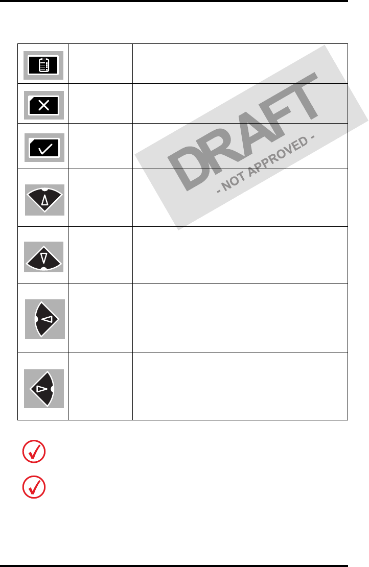
The Drystar 5302 keypad features the following keys:
Key-
operator key
To access the advanced functions of the key-
operator mode. Refer to Chapter 3, ‘Advanced
operation (Key-operator mode)’.
Escape key To quit the current function or exit a menu without
saving modifications.
Confirm key
(In key-operator mode)
•To select a menu.
• To accept an entry in a menu.
Up key
• To move the cursor to the previous entry field.
• To scroll upwards.
• To increment the number in a(n)
(alpha)numerical entry field.
Down key
• To move the cursor to the next entry field.
• To scroll downwards.
• To decrement the number in a(n)
(alpha)numerical entry field.
Left key
• To scroll backwards through multiple choices
within a field.
• To move the entry position in a(n)
(alpha)numerical entry field from right to left.
• To toggle between values in a field.
Right key
• To scroll forwards through multiple choices
within a field.
• To move the entry position in a(n)
(alpha)numerical entry field from left to right.
• To toggle between values in a field.
All keys (except the key-operator key) have an LED that is on when the key is valid
in a certain situation.
You can press and hold down an arrow key to scroll quickly through a list or a
menu.

27
2831A EN 20041201 Introducing the Drystar 5302
DRYSTAR 5302 USER MANUAL
The display
The Drystar 5302 control panel has a backlit LCD display. We distinguish two
panel types depending on the selected language:
•a backlit LCD display with 4 lines for Western languages (e.g. Dutch,
French, Portuguese, Swedish, ...).
•a backlit LCD display with 2 lines for Eastern language (e.g. Greek,
Chinese, Korean, Polish, ...).
Whether a display is translated or not depends on the operating mode.
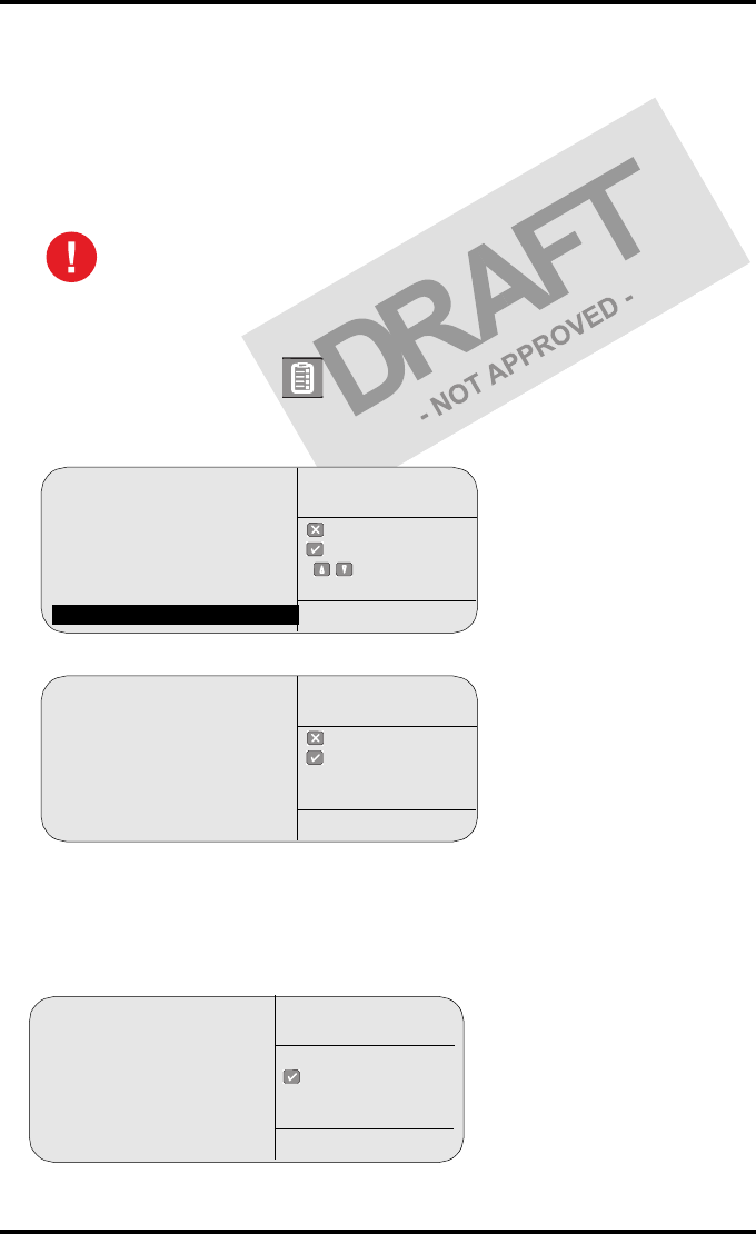
General display features
The figure below shows how the display is illustrated in this manual:
The visible display lines are indicated in the grey zone. The other possible
lines are shown in the white area and can be reached by scrolling using the
Up/Down arrow keys on the Keypad.
In the upper right corner, the current printer status is displayed:
•In Operator mode, two characters display the print queue status. Refer to
‘Managing the print queue’ on page 35.
•In Key-operator mode, two characters are displayed in reverse video to
indicate the current menu- or submenu level (e.g. ‘KO’ for Key-operator
main level).
•A warning, an error or a maintenance request is displayed respectively with
the character W, E and M.
please WAIT
Self Test
proceeding
Autotest:
CZEKAJ...
1 Show settings
2 Change settings
3 Print image
4 Save configuration
5 Restore config.
6 Calibration
7 Service actions
8 Quality control
9 Installation
KO
Reachable with Up/Down arrow keys
Visible
28 2831A EN 20041201Introducing the Drystar 5302
DRYSTAR 5302 USER MANUAL
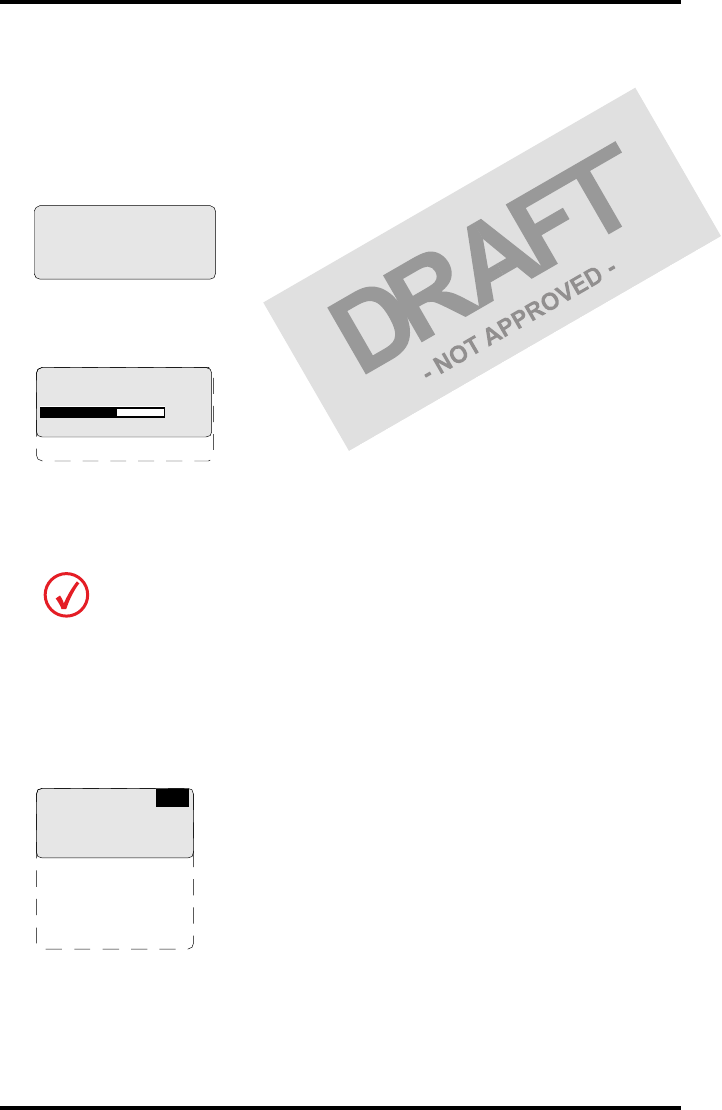
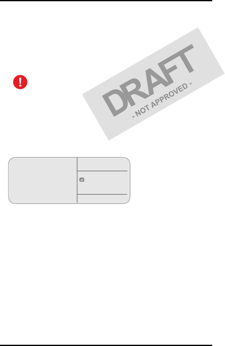
Operator mode
In operator mode, appropriate information is displayed in accordance with
the status of the printer.
The operator basic screen looks as follows, indicating that the Drystar 5302 is
ready for operation and that no job is currently being executed.
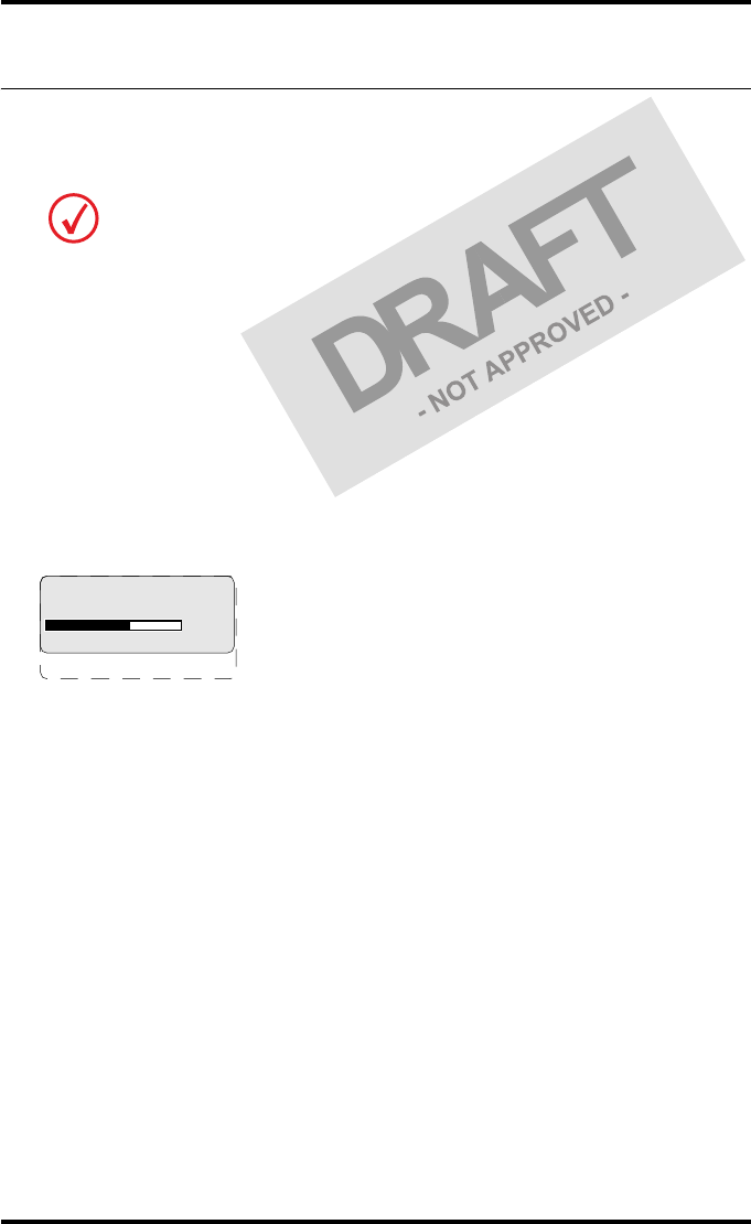
When the printer is busy with at least one print job, the print queue screen is
displayed:
The progress indicator keeps the user informed of the progress of a process
(e.g., calculation of a bitmap, printing of a film). The line is gradually filled
from left to right, from 0% to 100% as the process proceeds.
Refer to ‘Managing the print queue’ on page 35.
Key-operator mode
In key-operator mode, operation is menu driven. The menu displays the key-
operator functions.
The display shows only four lines. In the above figure, they are indicated in
the grey zone. The other possible lines are shown in the white area and can be
reached by scrolling using the Up/Down arrow keys on the Keypad.
On the print queue screen the modality name defined during installation will be
used to refer to the corresponding modality. In case a nickname (daily used name)
has been defined during installation, this nickname will be used.
READY
Modaname 10:21:34 PR
film 1 of 6
62%
Modaname 10:21:34 CA
xx Jobs in memory WA
1 Show settings
2 Change settings
3 Print image
4 Save configuration
5 Restore config.
6 Calibration
7 Service actions
8 Quality control
9 Installation
KO
Reachable with Up/Down arrow keys
Visible

29
2831A EN 20041201 Introducing the Drystar 5302
DRYSTAR 5302 USER MANUAL
The active keys are indicated by their respective LEDs.
Data entry
When entering numerical or alphanumerical data, always adhere to the
following principles:
•Only (alpha)numerical data can be entered.
•During data entry, the field is displayed in reverse mode.
•Increment the number in a(n) (alpha)numerical entry field by pressing the
Up key. Transition from 9 to 0 of one figure will also increment the next
figure to the left, respecting the valid limits of the range.
•Decrement the number in a(n) (alpha)numerical entry field by pressing
the Down key. Transition from 0 to 9 of one figure will also decrement the
next figure to the left, respecting the valid limits of the range.
•Move the entry position in a(n) (alpha)numerical entry field from right to
left by pressing the Left key.
•Move the entry position in a(n) (alpha)numerical entry field from left to
right by pressing the Right key.
•Press and hold down a key to repeat arrow key actions.
•To accept an entry in a menu, press the Confirm key.
•A short beep acknowledges and terminates the entry.
•The Drystar 5302 will sound a long beep if you press a key that is not to be
used at that moment.
30 2831A EN 20041201Introducing the Drystar 5302
DRYSTAR 5302 USER MANUAL
Switching on the Drystar 5302
Follow the procedure below to ensure proper startup of the Drystar 5302 and
to check that everything is working correctly.
1Check that the power cord is plugged in and then switch on the printer by
pressing the Power/Reset button.
On the display, the following message is displayed. After a short while, a progress
indicator will show the proceeding of the self-test.
•If anything goes wrong during the self-test, refer to ‘Startup errors’ on page 172 of
the Drystar 5302 Reference manual.
Before switching on the Drystar 5302, read the safety instructions. Refer to ‘Safety
precautions’ on page 9.
Please WAIT
Self Test
proceeding
62%
31
2831A EN 20041201 Introducing the Drystar 5302
DRYSTAR 5302 USER MANUAL
2The printer is ready for operation:
•If, on the front panel display, the READY message is shown, the status indicator LED
is constantly green.
•If, on the front panel display, the print queue screen is shown, the status indicator
LED is green and blinking.
3Make sure that the printer is loaded with appropriate consumables.
It takes 13 minutes (starting up of the Drystar 5302 and heating up of the thermal
print head) before you can start printing. The display will inform you that the
printer is warming up:
Refer to page 38 for detailed information on loading films.
If the job status displays a warning or error indication, refer to ‘Troubleshooting
checklist’ on page 65.
READY
WARMING UP
Please wait
Modaname 10:21:34 PR
film 1 of 6
62%
Modaname 10:21:34 CA
xx Jobs in memory WA
32 2831A EN 20041201Introducing the Drystar 5302
DRYSTAR 5302 USER MANUAL
Switching off the Drystar 5302
When you want to switch off the printer, it is recommended to follow the
procedure as described below, to make sure that any pending print jobs have
finished printing.
1Make sure that pending jobs are correctly finished. If necessary, follow the
procedure to stop printing.
2Press the Power/Reset button to switch off the Drystar 5302.
•If the printer is ready, it shuts down immediately:
•If the printer is busy printing images, it will first print all images in the memory before
shutting down:
•If there is an error/warning/incident during power off and there are still unprinted
images in the memory, the following message is displayed:
Press the Confirm button (YES) to proceed with the power-off, or the Escape button
(NO) to quit.
Powering off the printer with unprinted images in memory may result in
image loss!
Power off initiated
Please wait
Power off after
finishing images in
memory
Please wait
Are you sure to
power off the
printer? (images in
queue will be lost)

34 2831A EN 20041201Basic operation (Operator mode)
DRYSTAR 5302 USER MANUAL
Overview of operator functions
This section focuses on the basic operating principles of the Drystar 5302.
After reading this chapter, the operator should be able to produce diagnostic
usable hardcopies. No special technical skills are required.
All basic operator functions can be activated directly by pressing a single key
on the keypad.
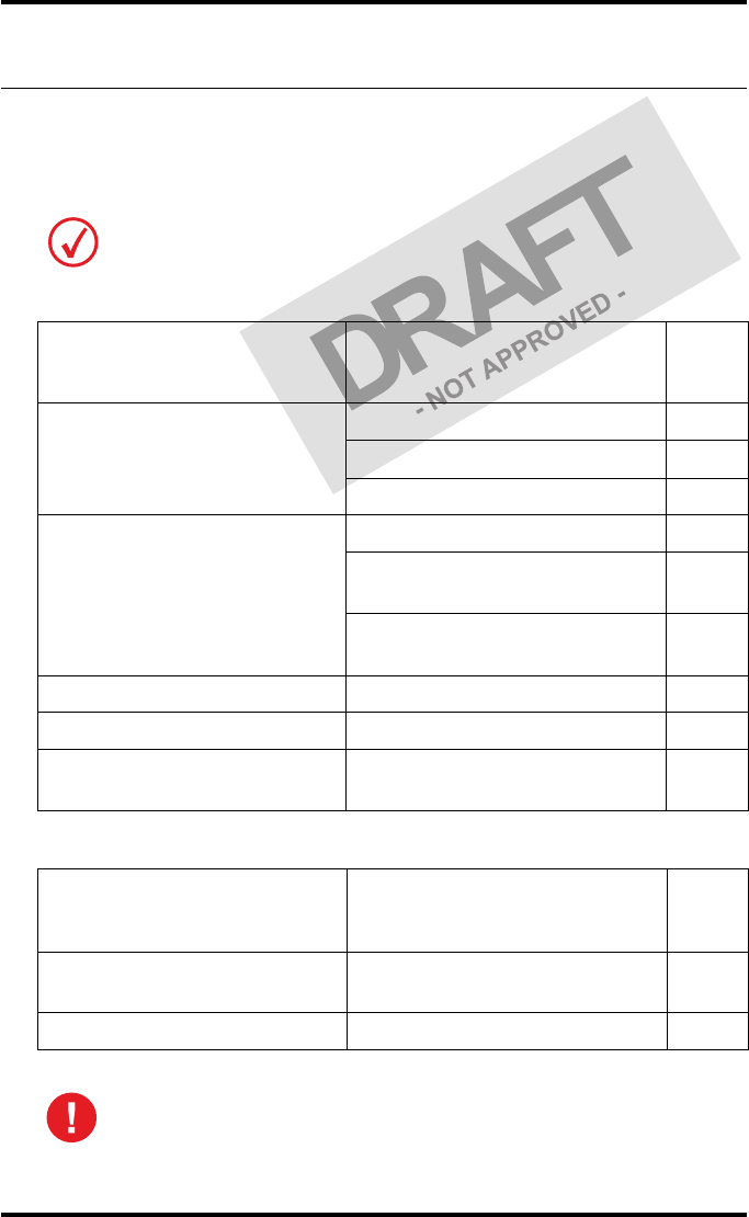
Function / Task Description Page
‘Managing the print queue’
Jobs that have been received are put
in a print queue, waiting to be
printed.
35
‘Loading films’ Instructions for loading new films
on the printer. 38
35
2831A EN 20041201 Basic operation (Operator mode)
DRYSTAR 5302 USER MANUAL
Managing the print queue
You can always check the status of the print jobs.
Checking the print queue
If jobs have been transmitted from the network to the Drystar 5302, they are
put in the print queue on a first in, first out schedule. New jobs that are added
to the queue get the ‘waiting’ status.
As soon as the last film of a job is ejected in the output tray, the next job that
has been calculated will be put in printing status.
Example of the print queue screen:
•The first line shows information on the job that is currently being printed:
the modality name, the time of receipt of the job and the job status (refer to
the table below).
•The second line shows how many films are to be printed for the current job
and also which film from that total is currently being printed.
•The progress indicator keeps the user informed of the progress of a
process (e.g., calculation of a bitmap, printing of a film). The line is
gradually filled from left to right, from 0% to 100% as the process
proceeds.
•The last line (reachable by using the down arrow key) displays the number
(xx) of print jobs that are in the Waiting (WA) status. These jobs have been
loaded into the print queue and they are waiting to be printed.
Keep in mind that one print job can hold several films to be printed. In accordance
with the acquisition modality used and with the actual settings, films can be
grouped in a folder to be submitted as one print job for the Drystar 5302. Refer to
the User manual of the acquisition modality for more information.
Modaname 10:21:34 PR
film 1 of 6
62%
Modaname 10:21:34 CA
xx Jobs in memory WA

36 2831A EN 20041201Basic operation (Operator mode)
DRYSTAR 5302 USER MANUAL
A description of the possible status of the jobs is listed in the table below:
Status Description
PR Printing Printing of this job is in progress.
CA Calculating The necessary calculations are already being
made before printing of the job can be started.
WA Waiting Jobs are queued in the printer memory.
On the print queue screen the modality name defined during installation will be
used to refer to the corresponding modality. If there is also a nickname (daily used
name) defined during installation, the nickname is used.
37
2831A EN 20041201 Basic operation (Operator mode)
DRYSTAR 5302 USER MANUAL
About Drystar 5302 consumables
The Drystar 5302 can handle blue-transparent and clear-transparent films.
Available film formats are 8x10”, 10x12”, 11x14”, 14x14” and 14x17”.
When a new film pack is loaded, the Film Identification tag is read and the
printer settings are automatically adjusted.
The key-operator can overrule the film settings for the input tray. Refer to
‘Changing the configuration settings’ on page 56 of the Drystar 5302 Reference
manual.
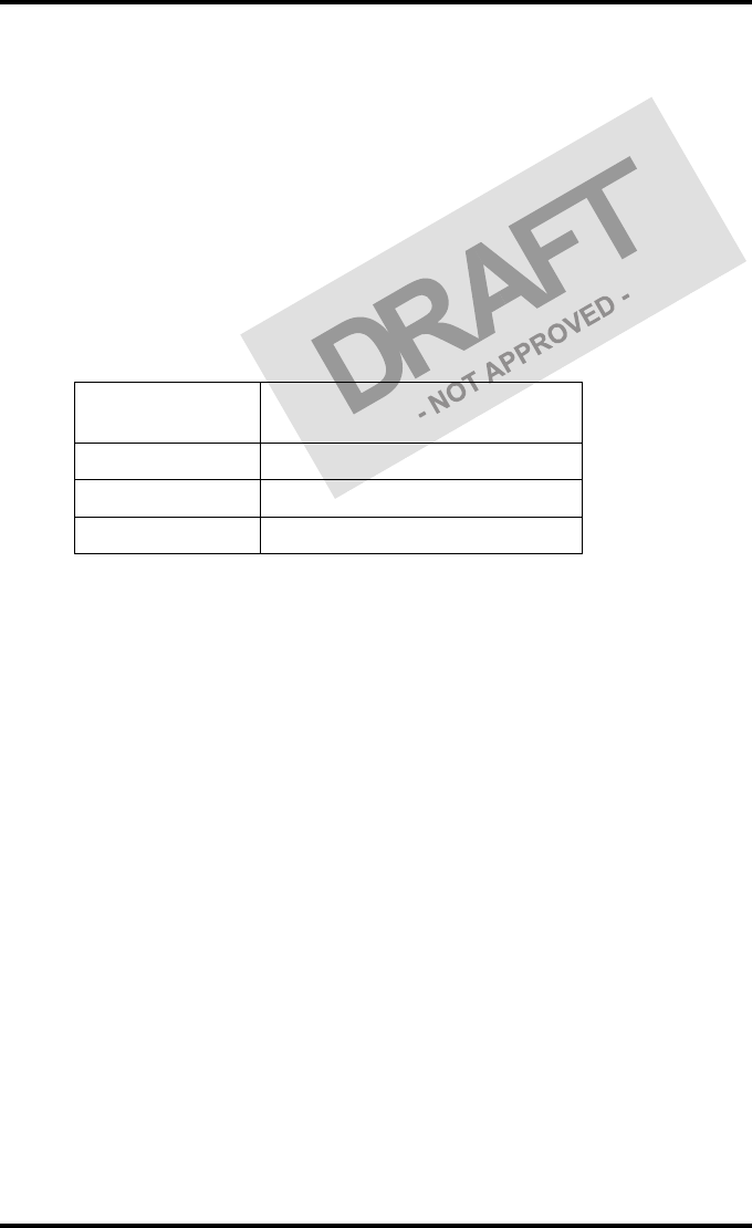
The following film types can be used:
Drystar DT2 B 8x10” up to 14x17”
Drystar DT2 C 8x10” up to 14x17”
If you want to change the film format, the tray configuration must be modified.
Refer to ‘Drystar 5302 network configuration’ on page 148 of the Drystar 5302
Reference manual for more information.
10 x 8"
10 x 12"
14 x 11"
14 x 14"
14 x 17"
38 2831A EN 20041201Basic operation (Operator mode)
DRYSTAR 5302 USER MANUAL
Loading films
This section describes how to load the Drystar 5302 with appropriate films.
The Drystar 5302 can be loaded with 8x10”, 10x12”, 11x14”, 14x14” and
14x17” films.
The Drystar 5302 will inform you in several ways when a film tray is empty:
•an audible signal,
•the status indicator LED is flashing (red color),
•the display screen shows a message informing you that the input tray is
empty.
When the Drystar 5302 is printing or calculating and an input
tray is empty:
1The display shows the following message:
2Wait while the printer finishes printing any current jobs.
When the film path is cleared, proceed with step 3.
The Drystar 5302 can be loaded with new films in full daylight. Loading films is
easy and can be done very quickly. Follow the procedures as described in this
section.
The procedure is slightly different, depending on the fact whether the Drystar 5302
is printing/calculating or in the ready state.
When the printer is in the ready state, go to Step 3.
Make sure not to load more than one film pack in an input tray. Loading
more than one film pack in the input tray may damage the Drystar 5302.
Lower input tray empty
DO NOT OPEN TRAY YET
Get new film pack
39
2831A EN 20041201 Basic operation (Operator mode)
DRYSTAR 5302 USER MANUAL
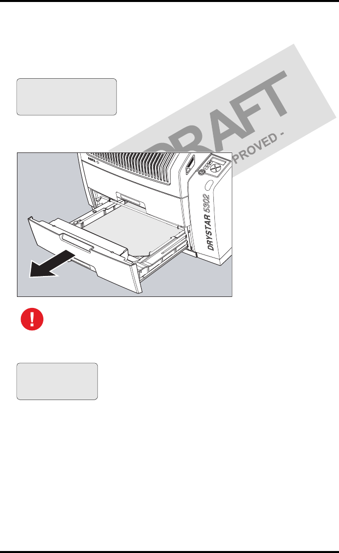
When the Drystar 5302 is in the ready state and an input tray is
empty:
3The display shows the following message:
4Open the empty input tray.
5The printer is ready to receive a new film when the following message appears:
To avoid possible film jams, make sure to open input tray all the way.
Lower input tray empty
OK to Open the
INPUT TRAY
Remove cover sheet
from tray
Load new film
Close tray
40 2831A EN 20041201Basic operation (Operator mode)
DRYSTAR 5302 USER MANUAL
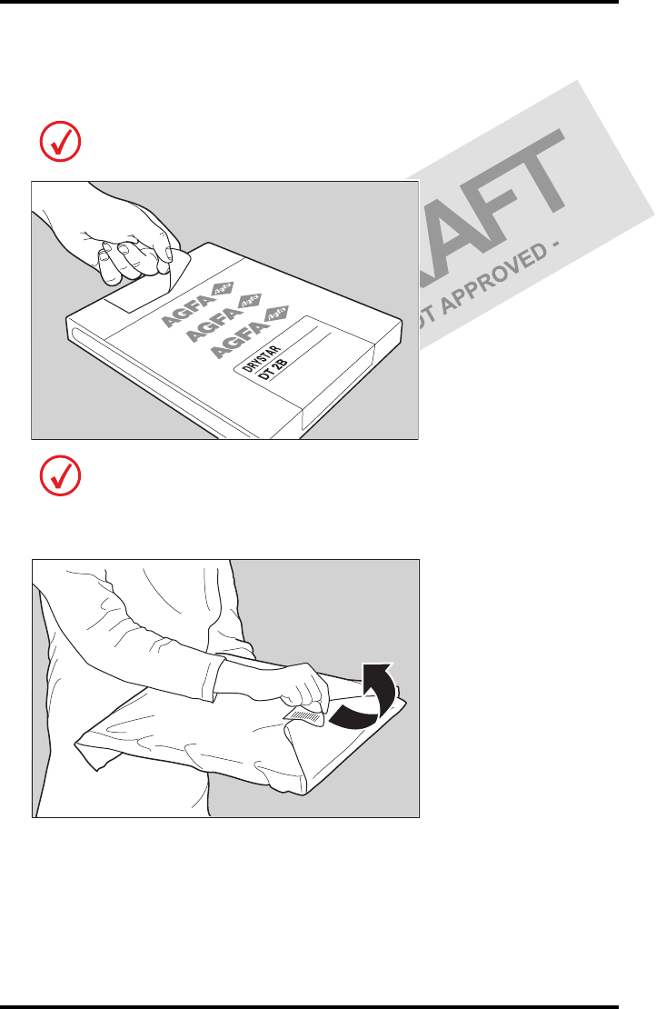
6Remove the white (protective) film sheet.
7Take film pack, and open it.
8Remove the sticker from the film pack.
Verify that the film type on the film pack corresponds with the sticker on the tray! If
you do use an other film type, you are advised to change the label on the tray.
You can put the film pack onto a table to make manipulation easier. Before you do
this, make sure that the table is dust-free!
41
2831A EN 20041201 Basic operation (Operator mode)
DRYSTAR 5302 USER MANUAL
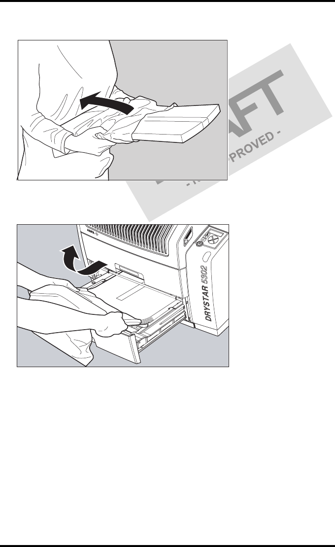
9Remove the plastic film bag partially.
10 Slide the film pack into the input tray, and remove the plastic film bag
completely.
42 2831A EN 20041201Basic operation (Operator mode)
DRYSTAR 5302 USER MANUAL
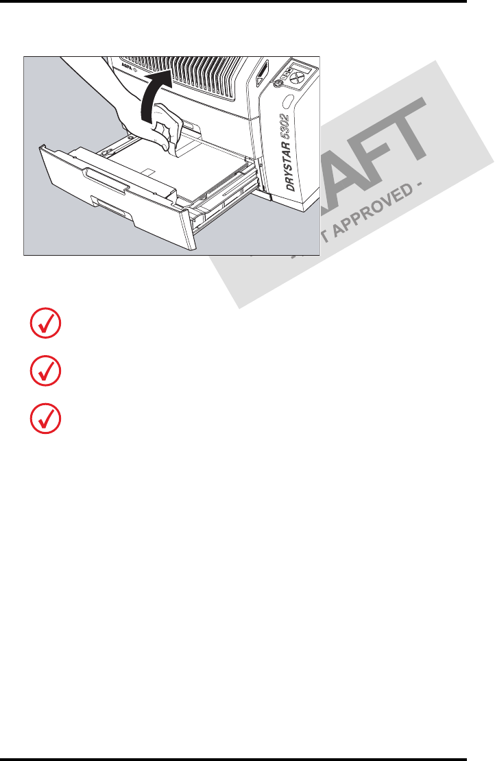
11 Tear the plastic tape from around the film pack.
12 Close the input tray.
The Drystar 5302 resumes printing as soon as the tray is closed.
Loading instructions are also available on the input tray cover.
Never reuse a jammed film. Refer to ‘Clearing of film jams’ on page 161 of the
Drystar 5302 Reference manual.
43
2831A EN 20041201 Basic operation (Operator mode)
DRYSTAR 5302 USER MANUAL
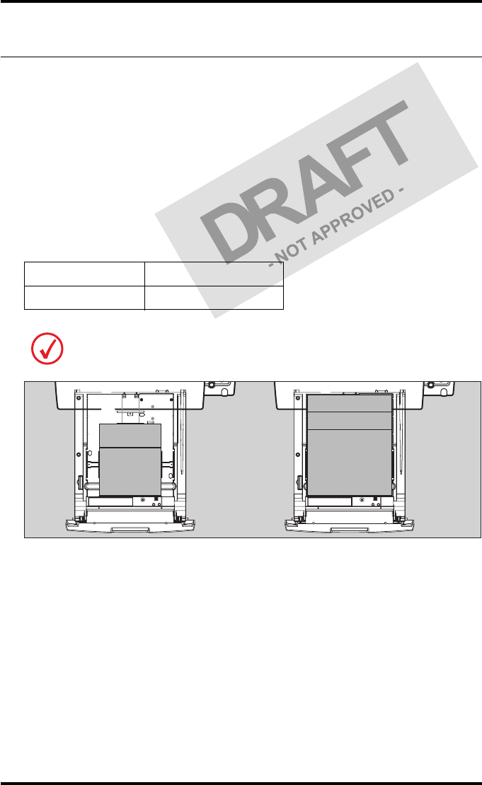
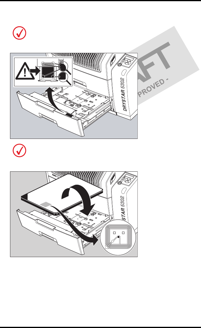
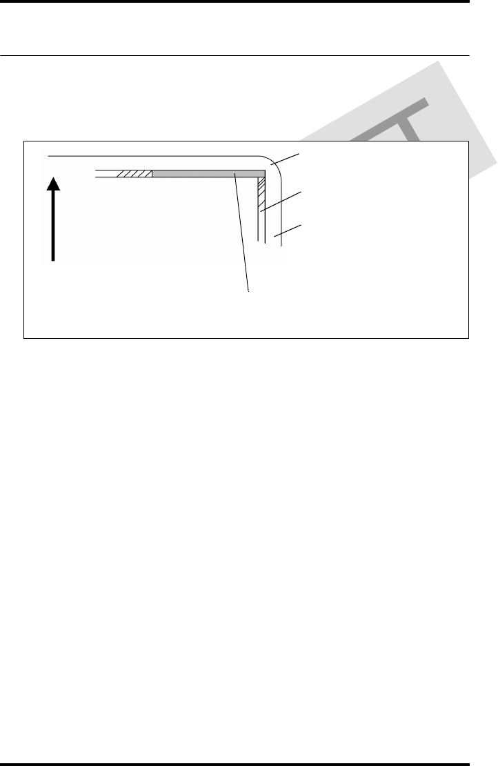
Checking the correct position of a film in the input tray
You can verify that the film is properly loaded by watching the lower right corner of
the films in the input tray. The rounding of this corner should be smaller than the
other three corners. This is also indicated on the sticker at the right side of the input
tray cover.
When a new film is loaded, the Film Identification tag is read and the printer
settings are automatically adjusted. The Film Identification tag is located on the
protective sheet on the backside of the film pack. The figure below shows the film
pack upside down.

44 2831A EN 20041201Basic operation (Operator mode)
DRYSTAR 5302 USER MANUAL

46 2831A EN 20041201Advanced operation (key-operator mode)
DRYSTAR 5302 USER MANUAL
Overview of key-operator functions
The key-operator menus make it possible to use the Drystar 5302 advanced
functions.
For general information on the key functions of the Drystar 5302, refer to ‘The
user interface’ on page 20.
Overview
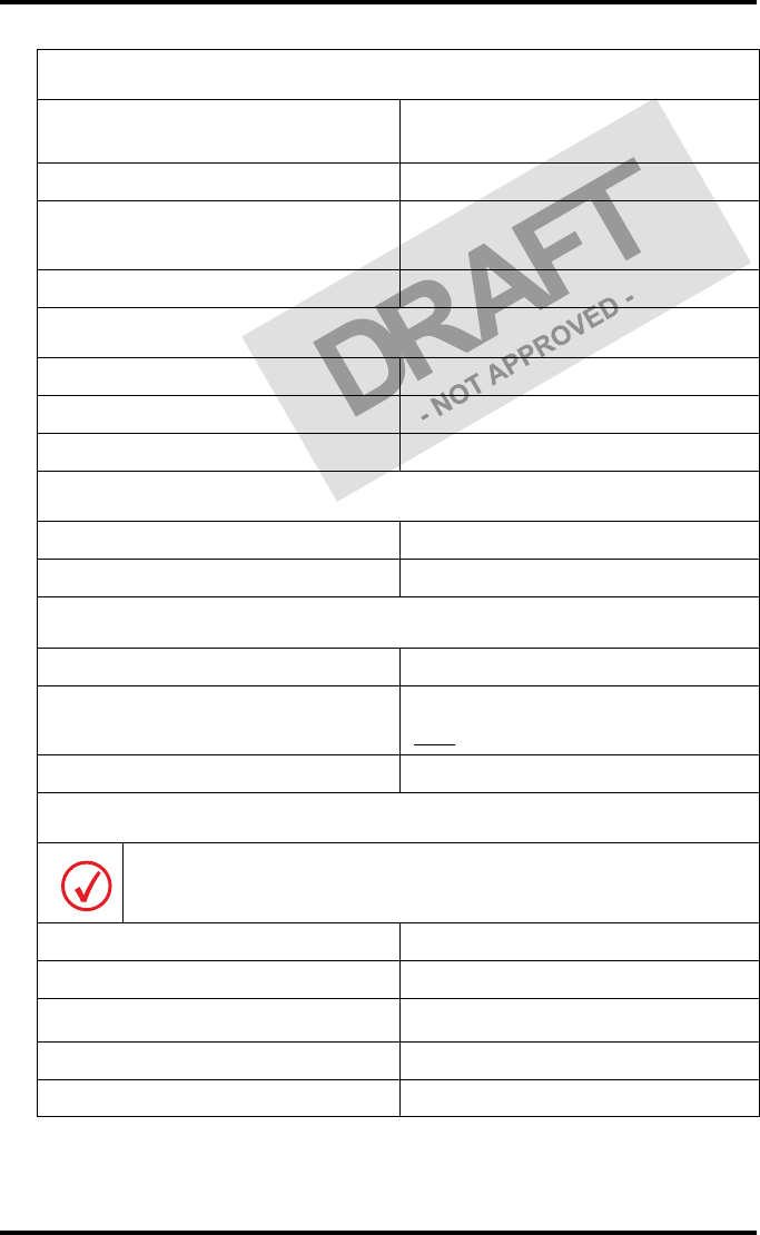
The Drystar 5302 features the following functions on the main menu level of
the key-operator mode:
These functions are described in detail in the Drystar 5302 Reference manual.
Menu item Function
Page
(Ref.
Man.)
Show settings To consult the current settings of the printer.
50
Change settings To change the current settings of the printer.
56
Print image
To print one of the Drystar 5302 test images.
To load and print images from an external
CF-card.
86
Save configuration To make a backup of the printer settings.
90
Restore
configuration To restore the backup of the printer settings.
92
Calibration To calibrate the printer.
97
Service actions To view error, repair and maintenance data.
105
Quality Control To perform the QC procedure.
(User
Manual)
47
Installation To install or update the Drystar 5302 software.
118
Refer to the indicated page of the Drystar 5302 Reference manual for an
explanation of the function and the appropriate procedures.

47
2831A EN 20041201 Advanced operation (key-operator mode)
DRYSTAR 5302 USER MANUAL
Quality Control
In order to establish and maintain consistent image quality, a regular
evaluation of image quality is advised.
The Drystar 5302 contains an automatic QC feature that has been designed to
comply with the grayscale reproduction constancy test, according to the
international standard IEC 1223-2-4.
Local Regulations may require other procedures.
The Drystar 5302 QC procedure consists of two main steps:
•Before initial use, establishing a number of reference values that will be
used for further follow-up and verifying initial image quality.
•After establishing these values, performing regular daily, weekly and
annual quality tests.
The results of these tests are recorded on Quality Control Charts.
The QC image (Refer to ‘QC test image’ on page 52) has several additional
fields where the QC data can be filled in. This image should be filed as part of
the QC procedure.
For more information, please refer to ‘Quality Control Charts’ on page 75.

48 2831A EN 20041201Advanced operation (key-operator mode)
DRYSTAR 5302 USER MANUAL
Establishing the reference values and verifying image quality
After installation of a new Drystar 5302 and before initial use you must
establish Quality Control aim values. These values will be used as the base
line for comparison when daily Quality Control is done. These values should
be determined again after major service, repair or software update.
The following Quality Control aim values must be determined:
•The daily operating density levels. Refer to ‘Establishing the daily operating
reference density levels’ on page 49.
•Drystar 5302 image geometry. Refer to ‘Establishing the image geometry
reference values’ on page 52.
Once Quality Control aim values are established you must evaluate the
Spatial Resolution, the Artifact Levels and the Low Contrast Visibility to
determine if the image quality is acceptable. Refer to ‘Verifying Acceptable
Spatial Resolution, Artifact Levels and Low Contrast Visibility’ on page 54.
The Quality Control aim values, the Spatial Resolution and Artifact Levels and
the Image Geometry values are all recorded on the Quality Control charts.
Refer to ‘Quality Control Charts’ on page 75.
On these charts, the following test conditions are also recorded:
•The type and serial number of the Drystar 5302.
•The type and emulsion number of the film used to determine the reference
values.
•The time (day, month, year) that the values were established.
Before you can establish the daily operating levels, the Drystar 5302 must
be switched on for at least 15 minutes and it must be calibrated as well.
Refer to ‘Switching on the Drystar 5302’ on page 30 and ‘Performing the
calibration procedures’ on page 97 of the Drystar 5302 Reference manual.
49
2831A EN 20041201 Advanced operation (key-operator mode)
DRYSTAR 5302 USER MANUAL
Establishing the daily operating reference density levels
This procedure enables you to establish the base line values for:
•Low density
•Mid density
•High density
To establish the daily operating levels, proceed as follows:
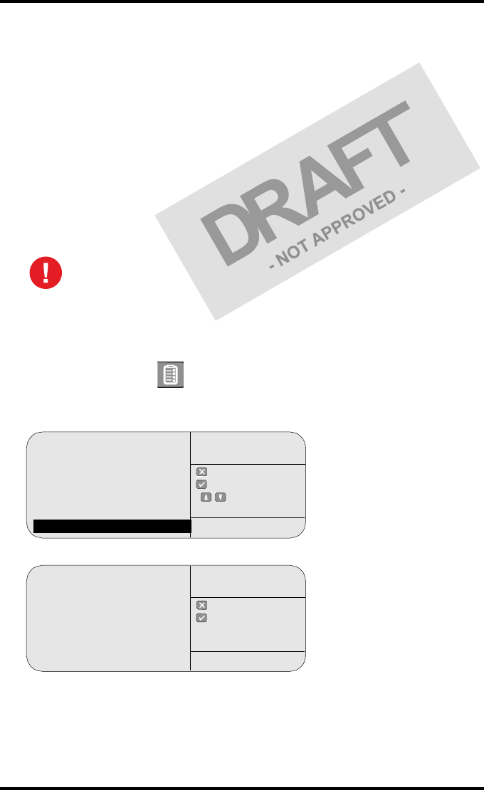
1Press the Key-operator key to enter the Key-operator mode.
2Press the down key seven times, followed by the ok key to select ‘QC’.
The ‘QC’ screen appears:
3Press the ok key to continue.
The Drystar 5302 will automatically print the QC Test image.
4After the image is printed, the system will display the optical density values:
The densitometer of the Drystar 5302 is calibrated at installation.
Authorized service personnel should recalibrate the densitometer
annually or after major service or repair.
1 Show settings
2 Change settings
3 Print image
4 Save configuration
5 Restore configuration
6 Calibration
7 Installation
8 QC
quit
ok
select
Key-operator
main menu
QC
Start printing test image
to perform:
daily / weekly
and yearly control
quit
ok
Key-operator
QC
QC
Internal Density readings
Low density :0.26
Mid density :1.35
High density :1.89
(copy on control chart)
ok
Key-operator
QC
50 2831A EN 20041201Advanced operation (key-operator mode)
DRYSTAR 5302 USER MANUAL
The displayed values represent the following steps on the test film:
•Low density: the density of the Low density step.
Target: 0.4.
•Mid density: the density value of the Mid density step.
Target: 1.2.
•High density: the density value of the High density step.
Target: 2.0.
5Record the density levels on the Drystar 5302 Chart 1 (‘Determination of the
operating levels’). Refer to ‘Quality Control Charts’ on page 75.
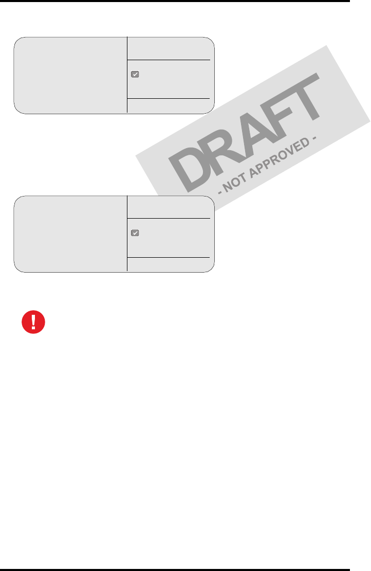
6Press the ok key. The following screen is displayed:
If the mid density value does not meet or exceeds the recommended
values, the reason must be found and the problem solved before any
further clinical films can be printed.
Refer to ‘Preventive maintenance schedule’ on page 59 and ‘Maintaining image
quality and resolving image quality problems’ on page 173 of the Drystar 5302
Reference manual, or call your local Agfa service organization.
QC
Proceed with the QC proce-
dure as stated in the User man-
ual ok
Key-operator
QC
51
2831A EN 20041201 Advanced operation (key-operator mode)
DRYSTAR 5302 USER MANUAL
7Press the ok key to return to the main menu.
8Repeat 1 steps through 7 once a day for five consecutive days, as indicated on
the Drystar 5302 Chart 1.
9Calculate the average value of the densities from the five images. These values
represent operating levels, or aim values, for each density.
10 Record the respective aim (average) values as the ‘Operating levels’ on the
Drystar 5302 Charts 2a and 2b (‘daily Drystar 5302 control chart’). Refer to
‘Quality Control Charts’ on page 75.
The calculated ‘Operating levels’ should be as following:
11 These charts will be used for the daily quality test. For more information, refer
to ‘Performing the daily QC test’ on page 55.
Operating Level Value
(according IEC 1223-2-4 or beter)
Low density 0.4 ± 0.05
Mid density 1.2 ± 0.15
High density 2.0 ± 0.2
52 2831A EN 20041201Advanced operation (key-operator mode)
DRYSTAR 5302 USER MANUAL
Establishing the image geometry reference values
1Print the QC test image or use the previously printed test image.
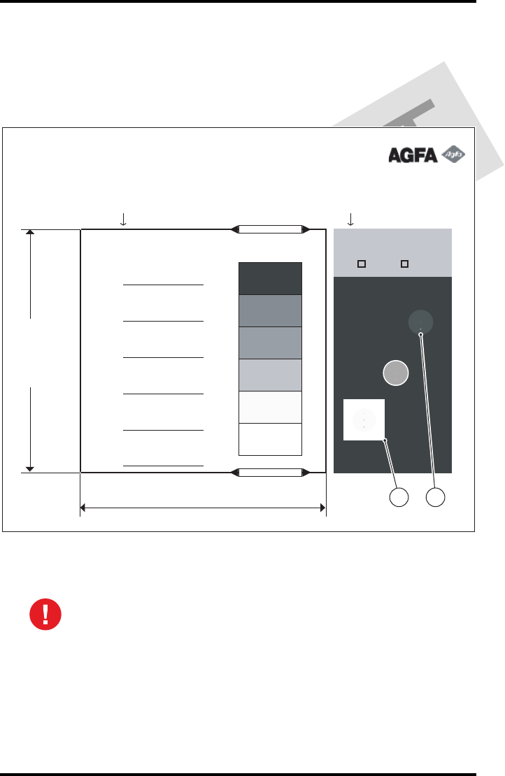
You should obtain an image looking like this (without the dimensions A and B):
QC test image
2To determine the reference values for geometry, measure the dimensions
A and B of the geometric square on the test image.
Make sure to measure distance A from the left edge of the left line to the
right edge of the right line and distance B from the upper edge of the
upper line to the lower edge of the lower line.
We strongly recommend using a 30 cm (12-inch) machinist scale with
0.5 mm divisions (1/64 inch).
Drystar 5302
Quality Control Test Image
Date: __________
Time: __________
Initials: ________
Weekly Spatial
Resolution Test
Geometry Test
Daily density test
Max D
Hi D
Mid D
Lo D
Base
+ Fog
DD
Density Difference
(Hi D - Lo D)
Sets of dots visible?
Yes No
Dimension A
Dimension B
1 2

53
2831A EN 20041201 Advanced operation (key-operator mode)
DRYSTAR 5302 USER MANUAL
3Record these values as reference dimensions A ref and B ref on the Drystar 5302
Chart 4 (‘Drystar 5302 Geometric Consistency Control Chart’). Refer to ‘Quality
Control Charts’ on page 75.
These charts will be used for the annual quality test. For more information, refer to
‘Performing the Annual QC tests’ on page 58.
4Save this film for future reference.

54 2831A EN 20041201Advanced operation (key-operator mode)
DRYSTAR 5302 USER MANUAL
Verifying Acceptable Spatial Resolution, Artifact Levels and Low Contrast
Visibility
1Print the QC Test image or use the previously printed QC Test image used to
establish the daily operating density levels.
2Visually check the QC test image for artifacts: no significant disturbing artifacts
should be visible.
3Check the spatial resolution in each of the three ovals. Within each oval there
are three groups, each having five dots. All five dots of each group must be
visible with a magnifying glass. The smallest cluster of 5 dots are only visible if
the viewing conditions are good.
4Record these values at the top of the Drystar 5302 Chart 3 (Drystar 5302
Artifacts and Spatial Resolution Control Chart). Refer to ‘Quality Control Charts’
on page 75.
5Check the Low Contrast Visibility at both the high (100 / 95%) and low end
(0 / 5%) of the density scale. You should be able to see the circle in the square
(refer to item 1 on the ‘QC test image’ on page 52) and the upper circle (refer to
item 2 on the ‘QC test image’ on page 52).
6These charts will be used for the weekly quality test. For more information,
refer to ‘Performing the Weekly QC tests’ on page 57.
Good viewing conditions are important for the correct interpretation of
both diagnostic and test images. Make sure that the lightbox intensity
(luminance) is between 2000 and 4000 cd/m² (4500 and 6500 °K). Use a
magnifying glass and use shutters to collimate. Make sure the ambient
light is low.
In case of significant artifacts or insufficient spatial resolution, the reason
must be found and the problem solved before any further clinical films can
be printed.
Refer to ‘Preventive maintenance schedule’ on page 59 and ‘Maintaining image
quality and resolving image quality problems’ on page 173 of the Drystar 5302
Reference manual, or call your local Agfa service organization.
55
2831A EN 20041201 Advanced operation (key-operator mode)
DRYSTAR 5302 USER MANUAL
Performing quality control (QC) tests
The following procedures must be performed daily, weekly or annually as
indicated.
The reason for performing quality control tests is to determine if any
significant image quality variation or deterioration has occurred which may
require corrective action. Comparing the results of the tests with the reference
values previously established does this.
This procedure allows the operator to take the necessary preventive actions
before any image quality loss can take place.
Performing the daily QC test
1Turn on the Drystar 5302 and wait at least for 15 minutes. Refer to ‘Switching on
the Drystar 5302’ on page 30.
2Press the Key-operator key to enter the Key-operator mode.
3Press the down key seven times, followed by the ok key to select ‘QC’.
The ‘QC’ screen appears:
4Press the ok key to continue.
The Drystar 5302 will automatically print the QC Test image.
This test must be performed every day before any clinical film can be
processed.
1 Show settings
2 Change settings
3 Print image
4 Save configuration
5 Restore configuration
6 Calibration
7 Installation
8 QC
quit
ok
select
Key-operator
main menu
QC
Start printing test image
to perform:
daily / weekly
and yearly control
quit
ok
Key-operator
QC
56 2831A EN 20041201Advanced operation (key-operator mode)
DRYSTAR 5302 USER MANUAL
After the image is printed, the system will display the optical density values:
5Record the density values on the Drystar 5302 Charts 2A and 2B (Drystar 5302
Daily Density Control Chart’). Also record the date and time of the test on the
charts and on the QC test images. Refer to ‘Quality Control Charts’ on page 75.
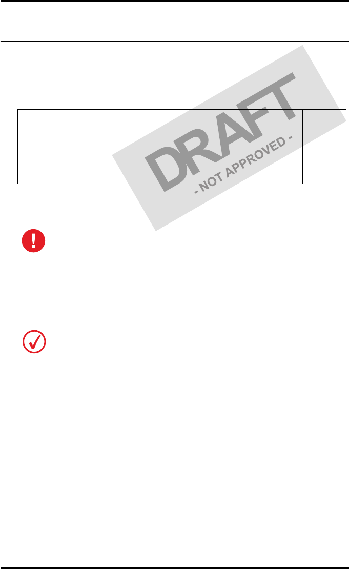
6Press the ok key. The following screen is displayed:
7Press the ok key to return to the main menu.
In case the measure results are not within the aim values, the reason for
the unacceptable density variations must be identified and resolved before
any further clinical films can be processed. This may include repeating the
film calibration procedure.
For possible causes of non-compliance and the respective actions, refer to
‘Preventive maintenance schedule’ on page 59 and ‘Maintaining image quality
and resolving image quality problems’ on page 173 of the Drystar 5302
Reference manual.
QC
Internal Density readings
Low density :0.19
Mid density :1.25
High density: 1.78
(copy on control chart)
ok
Key-operator
QC
QC
Proceed with the QC proce-
dure as stated in the User man-
ual
ok
Key-operator
QC

57
2831A EN 20041201 Advanced operation (key-operator mode)
DRYSTAR 5302 USER MANUAL
Performing the Weekly QC tests
Spatial Resolution, Artifact Test and Low Contrast Visibility
To identify artifacts and verify spatial resolution you must perform the
following test weekly or as needed for troubleshooting image quality
problems.
1Check the QC test image visually for artifacts: no significant disturbing artifacts
should be visible.
2Check the spatial resolution.
The test film also shows three squares which each contains an oval. These 3 ovals
contain 3 groups, each having 5 dots. All five dots of each group must be visible with a
magnifying glass. The smallest cluster of 5 dots are only visible if the viewing
conditions are good.
3Check the Low Contrast Visibility at both the high (100 / 95%) and low end
(0 / 5%) of the density scale. You should be able to see the circle in the square
(refer to item 1 on the ‘QC test image’ on page 52) and the upper circle (refer to
item 2 on the ‘QC test image’ on page 52).
4Record these values on the Drystar 5302 Chart 3 (Drystar 5302 Artifacts and
Spatial Resolution Control Chart).
Good viewing conditions are important for the correct interpretation of
both diagnostic and test images. Make sure that the lightbox intensity
(luminance) is between 2000 and 4000 cd/m² (4500 and 6500 °K). Use a
magnifying glass and use shutters to collimate. Make sure the ambient
light is low.
In case of significant artifacts, insufficient spatial resolution or failure of
any other recommended QC tests, the cause of the problem must be
identified, and corrective action must be taken before the Drystar 5302
can be used for any further clinical imaging.
Refer to‘Preventive maintenance schedule’ on page 59 and ‘Maintaining image
quality and resolving image quality problems’ on page 173 of the Drystar 5302
Reference manual, or call your local Agfa service organization for
assistance.

58 2831A EN 20041201Advanced operation (key-operator mode)
DRYSTAR 5302 USER MANUAL
Performing the Annual QC tests
Geometric Consistency Test
To be able to notice fluctuations in image size and aspect ratio, you must
perform this procedure once a year.
1First, perform the daily test.
2Use the QC test image of the weekly test and measure the dimensions A and B of
the geometric square. Refer to ‘Establishing the image geometry reference values’
on page 52.
3Record these values as measured dimensions A and B on Chart 4 (‘Drystar 5302
Geometric Consistency Control Chart’).
4Compare the measured A and B dimensions with the reference dimension
values, A ref and B ref on the Drystar 5302 Chart 4 (‘Drystar 5302 Geometric
Consistency Control Chart’).
The differences between measured dimensions of A and B and the reference values A
ref and B ref should be less than or equal to 1.0%.
5Check for image distortion.
6Calculate the aspect ratio by dividing A by B.
The result must be 1 +/- 0.01
Make sure to measure distance A from the left edge of the left line to the
right edge of the right line and distance B from the upper edge of the
upper line to the lower edge of the lower line.
We strongly recommend using a 30 cm (12-inch) machinist scale with
0.5 mm divisions (1/64 inch).
If the image size or distortion values are outside of limits, contact Agfa
service to resolve the problem.
59
2831A EN 20041201 Advanced operation (key-operator mode)
DRYSTAR 5302 USER MANUAL
Preventive maintenance schedule
The Drystar 5302 is designed for trouble-free service. Maintenance and
cleaning involve only some minor user tasks. Refer to the following pages for
the appropriate cleaning procedure.
Safety guidelines
•Do not lubricate the printer.
•Do not attempt to disassemble the printer.
•Do not touch the resistor line of the print head.
•Always switch off the Drystar 5302 and disconnect the power cord from
the outlet before carrying out any maintenance work inside the printer.
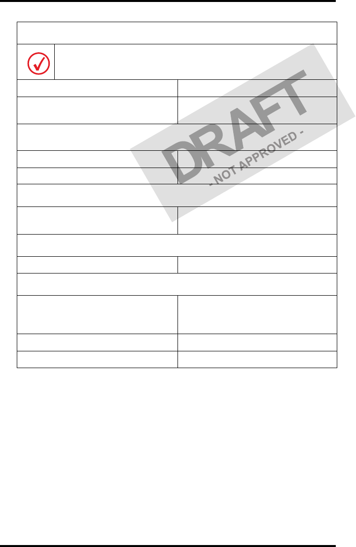
Interval What to do? Page
Ad hoc ‘Cleaning the exterior’ 60
When image quality tends to
degrade. An appropriate warning
message is displayed.
‘Cleaning the print head’ 61
To prevent damage to the printer while performing maintenance, observe
the following safety precautions:
Film jam removal or cleaning the printer head can be done without switching the
power off. Nevertheless, care should be taken and the ‘Safety precautions’ on page 9
should be respected.

60 2831A EN 20041201Advanced operation (key-operator mode)
DRYSTAR 5302 USER MANUAL
Cleaning the exterior
1Switch off the Drystar 5302 by following the procedure as described in
‘Switching off the Drystar 5302’ on page 32.
2Remove the power plug from the socket.
3Wipe the exterior of the printer with a clean, soft, damp cloth.
Use a mild soap or detergent if required but never use an ammonia–based cleaner. Be
careful not to get any liquid in the power cord port.
4Plug in the printer and switch it on by following the procedure as described in
‘Switching on the Drystar 5302’ on page 30.
61
2831A EN 20041201 Advanced operation (key-operator mode)
DRYSTAR 5302 USER MANUAL
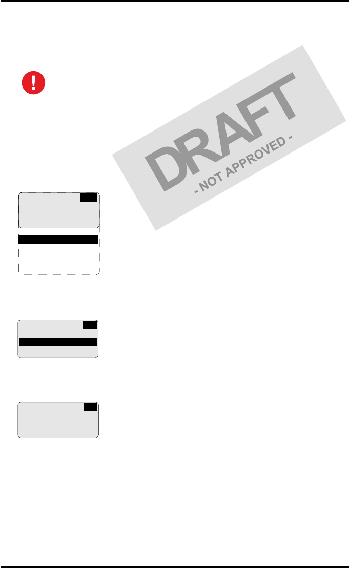
Cleaning the print head
To clean the print head:
1Press the Key-operator key to enter the key-operator mode.
2On the key-operator main menu, press the Down key five times, followed by the
Confirm key to select ‘Calibration’.
3On the Calibration menu, press the Down key, followed by the Confirm key to
select ‘Therm. Head clean.’.
4The ‘Thermal head cleaning’ screen will give step by step instructions on what
to do:
Print head cleaning must be done when image quality problems occur.
1 Show settings
2 Change settings
3 Print image
4 Save configuration
5 Restore config.
6 Calibration
7 Service actions
8 Quality control
9 Installation
KO
CA
CALIBRATION
1 Film Calibration
2 Therm. Head clean.
THERMAL HEAD
CLEANING
Open top cover
CA
62 2831A EN 20041201Advanced operation (key-operator mode)
DRYSTAR 5302 USER MANUAL
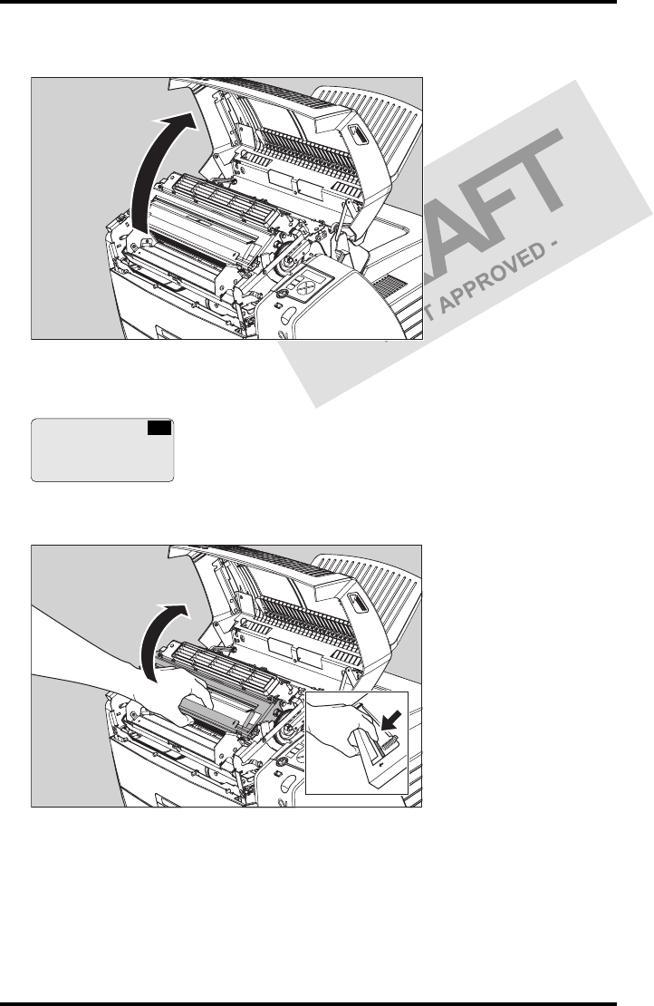
5Open the top cover.
6As soon as the top cover is opened, the ‘Thermal head cleaning’ screen
continues giving the following instructions:
7Open the hold-down bracket.
THERMAL HEAD
CLEANING
Clean thermal head
Close top cover
CA
63
2831A EN 20041201 Advanced operation (key-operator mode)
DRYSTAR 5302 USER MANUAL
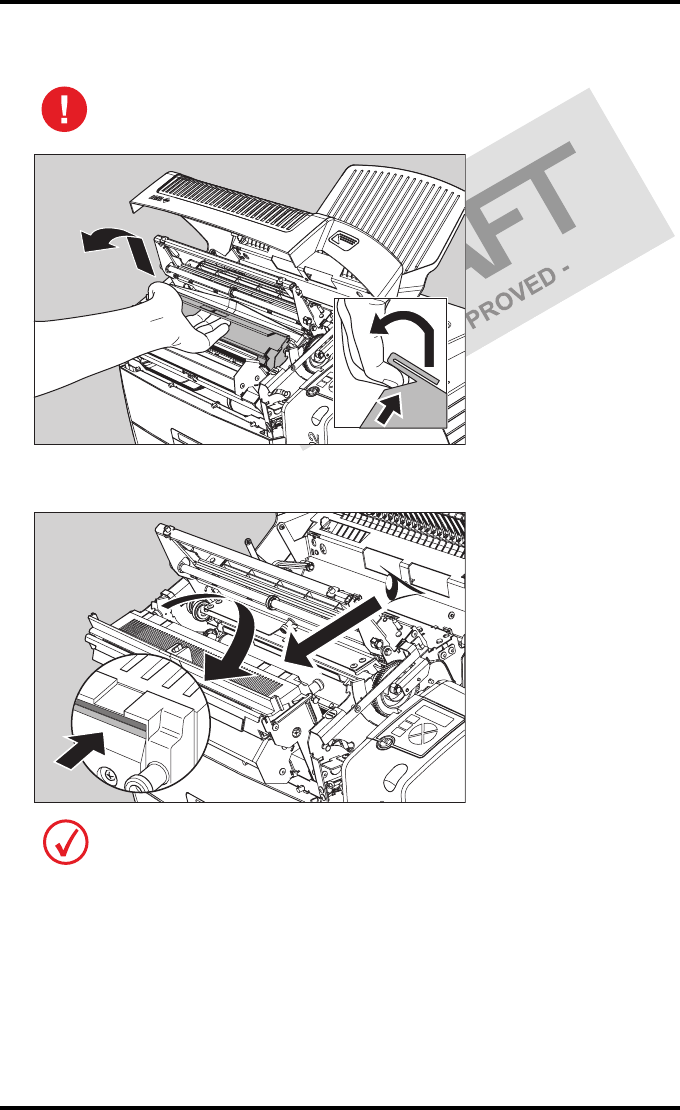
8Open the print head unit.
9Locate and check on sight the print head resistor line.
The print head unit can be warm.
Be careful not to touch the print head resistor line with your fingers.
64 2831A EN 20041201Advanced operation (key-operator mode)
DRYSTAR 5302 USER MANUAL
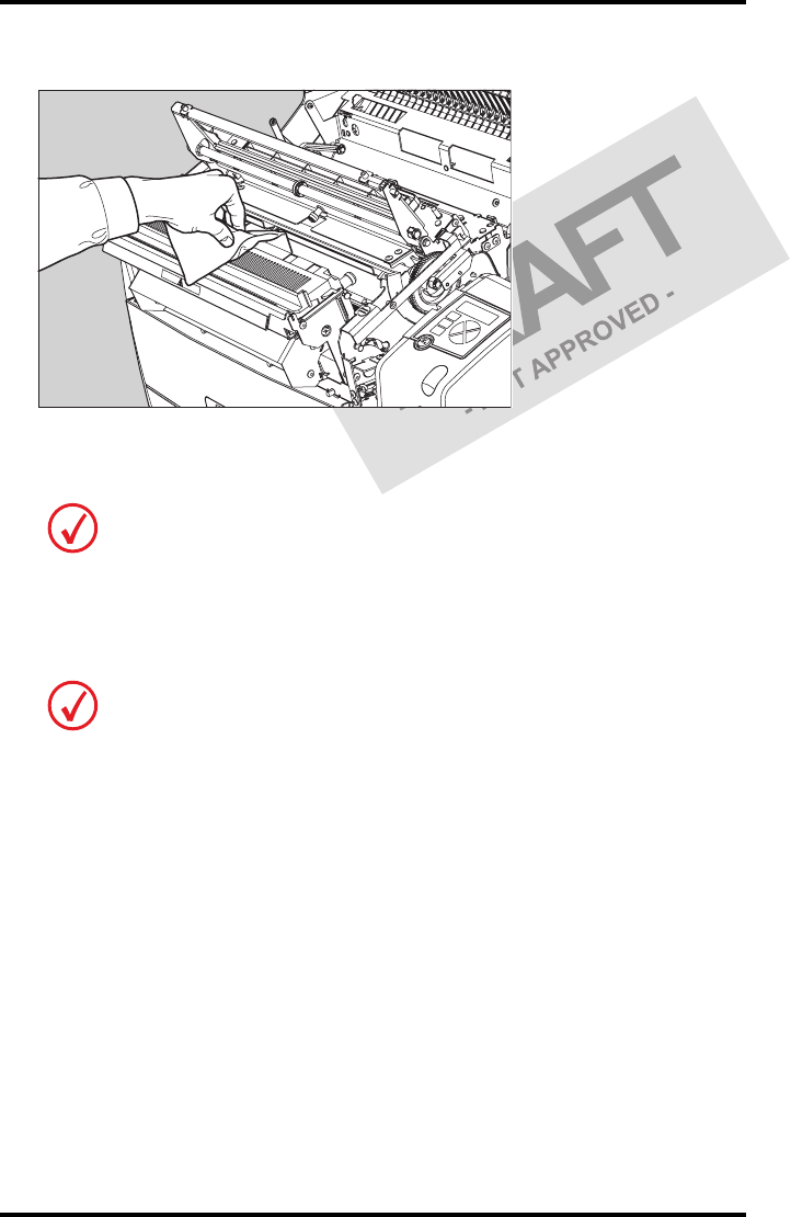
10 Clean the print head resistor line.
Gently pass over the resistor line a few times with a lint free cloth, slightly moistened
with Isopropyl alcohol or Ethanol. Do this only in one direction, i.e. from left to
right, without lifting the cloth.
11 Close the print head unit, the hold-down bracket and finally the top cover.
After you have cleaned the print head resistor line and you have closed the top cover,
the printer will restart automatically.
Do not apply any pressure on the print head because this pressure may cause
damage on the interconnections underneath the print head.
If residue dust is present as part of the cleaning procedure it will disappear after a
few prints.
65
2831A EN 20041201 Advanced operation (key-operator mode)
DRYSTAR 5302 USER MANUAL
Troubleshooting checklist
The table below lists some general problems which can occur when working
with the Drystar 5302.
•The Drystar 5302 does not print.
•The quality of the printed images is bad (printing remains possible).
Refer to the appropriate pages of the Drystar 5302 Reference manual.
Action Refer to
Page
(Ref.
Man.)
Check the Drystar 5302
‘Checking the status indicator LED’ 157
‘Checking the connections’ 158
‘Checking the print queue’ 160
Remove a jammed film
‘Film input tray jams’ 162
‘Film transport jams (clearing from
the top)’ 165
‘Unauthorized opening of the
printer’ 167
Resolve error messages ‘Checking error messages’ 159
Handle CF-card errors ‘Checking CF-card error messages’ 159
Resolve film identification
problems
‘The Film Identification tag is not
readable’ 168
Action Refer to
Page
(Ref.
Man.)
Resolve film quality problems ‘Persistent white dots or lines appear
in the transport direction’ 175
Resolve warning messages ‘Maintenance messages’ 177
Have electrical or mechanical defects repaired by skilled personnel only!

66 2831A EN 20041201Advanced operation (key-operator mode)
DRYSTAR 5302 USER MANUAL

Equipment information
sheet
Appendix A

68 2831A EN 20041201Equipment information sheet
DRYSTAR 5302 USER MANUAL
Specifications
Product description
Type of product Printer
Commercial name Drystar 5302
Original seller/manufacturer Agfa-Gevaert N.V.
Labelling
TÜV-, cULus-Certification Mark,
CE-marking
CCC Mark
Dimensions
Dimensions (approx. values in cm)
•Unpacked: widthtbd, lengthtbd,
height tbd
• Packed: width tbd, length tbd,
height tbd
Weight • Unpacked: approx. 90 kg
• Packed: approx. 120 kg
RAM memory 512 Mb
Mass storage media (internal/external) Compact Flash Type II
Electrical connection
Operating voltage 100-127 V; 220-240 V AC
No external mains fuses
Mains frequency 50/60 Hz
69
2831A EN 20041201 Equipment information sheet
DRYSTAR 5302 USER MANUAL
Network connectivity
Ethernet / connectors RJ45 twisted pair for 10/100Base-TX;
Serial RS232 connection
Network protocols (TCP/IP services) FTP, Telnet, HTTP, SMTP
Image formats DICOM (Default)
TIFF
Postscript Not available
Power consumption - heat dissipation
During operation 250 W - 900 kJ/h
In standby 70 W - 252 kJ/h
Peak power (absolute max. rating) 530 W - 1908 kJ/h
Protection against
Electrical shocks Class 1 (grounded)
Ingress of water IPXØ
Environmental conditions (operation)
Room temperature Between +15°C and +30°C
Relative humidity Between 20% and 75%
Note: Films may not become wet!
Atmospheric pressure 70 kPa - 106 kPa
Environmental storage conditions
Climate conditions for storage are in accordance with EN60721-3-1-class 1K4.
Room temperature Between -25°C and 55°C (storage)
Relative humidity Between 10% and 100%
Absolute humidity Between 0.1 g/m3 and 35 g/m3
Rate of change of temperature 1°C/min
Atmospheric pressure 70 kPa - 106 kPa
70 2831A EN 20041201Equipment information sheet
DRYSTAR 5302 USER MANUAL
Environmental transport conditions
Climate conditions for transport are in accordance with
EN60721-3-2-class 2K4.
Temperature Between -40°C and 70°C (transport)
Relative humidity not combined with
rapid temperature changes 95% at +45°C
Noise emission (method of measurement in accordance with DIN 45635
part 19)
During operation Max. 64 dBA
In standby Max. 54 dBA
Consumables
Drystar DT 2B and Drystar DT 2C 8x10”, 10x12”, 11x14”, 14x14” and
14x17”film sizes
Print technology
Direct thermal printing
Reliability
Estimated product life
(if regularly serviced and maintained
according to Agfa instructions)
> 5 years and > 125,000 films
Service interventions Max. 2 interventions / 3 years
Earthquake (standard) Meets the CA requirements
71
2831A EN 20041201 Equipment information sheet
DRYSTAR 5302 USER MANUAL
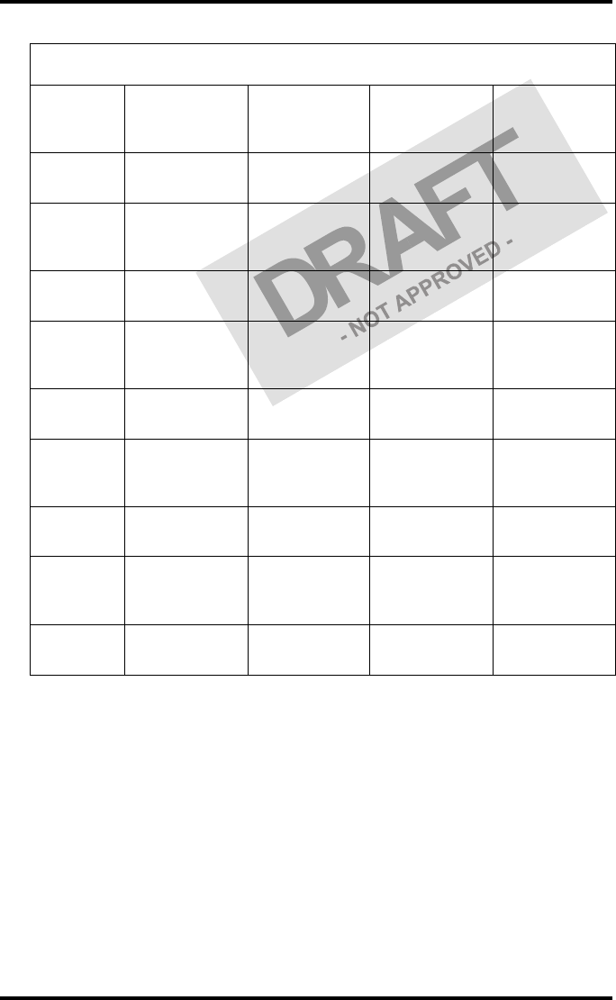
Imaging Array - Diagnostic area
Film size
8x10”
8” dimensions
in pixels
8” dimensions
in mm
10”
dimensions in
pixels
10”
dimensions in
mm
Diagnostic
area 2375.76 188.64 3072.24 243.94
Film size
10x12”
10”
dimensions in
pixels
10”
dimensions in
mm
12”
dimensions in
pixels
12”
dimensions in
mm
Diagnostic
area 3072.24 243.94 3652.84 290.04
Film size
11x14”
11”
dimensions in
pixels
11”
dimensions in
mm
14”
dimensions in
pixels
14”
dimensions in
mm
Diagnostic
area 3348.06 265.84 4358.13 346.04
Film size
14x14”
14”
dimensions in
pixels
14”
dimensions in
mm
14”
dimensions in
pixels
14”
dimensions in
mm
Diagnostic
area 4358.13 346.04 4302.72 341.64
Film size
14x17”
14”
dimensions in
pixels
14”
dimensions in
mm
17”
dimensions in
pixels
17”
dimensions in
mm
Diagnostic
area 4358.13 346.04 5232.19 415.44
72 2831A EN 20041201Equipment information sheet
DRYSTAR 5302 USER MANUAL
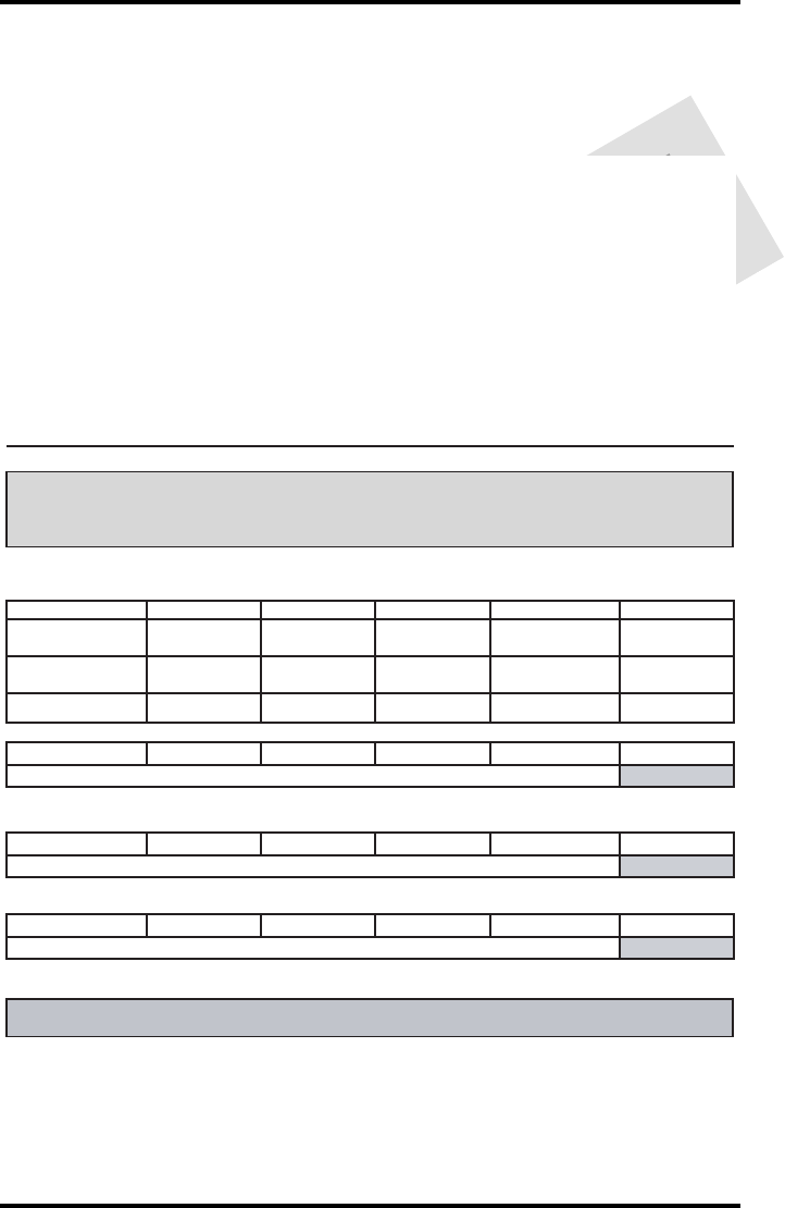
Viewing the System info area on a film
On the top right corner of each film, a “System info” area will be printed.
This info can only be read using a magnifying glass.
The System info area contains info about:
•Printer: (serial number, densitometer info, film counts, software version,
etc.),
•Controller (image source, date, time, etc.).
For more detailed information, refer to the Drystar 5302 Service
documentation.
Film
Diagnostic area
Clear border
Black border
System info area
Transport direction

73
2831A EN 20041201 Equipment information sheet
DRYSTAR 5302 USER MANUAL
Options and accessories
Mobile / Earthquake provisions
Hardware
The OPTIONAL mobile/earthquake installation kit allows you to use the
Drystar 5302 in a van, or to use it in unstable environment.
It contains the necessary equipment to fix the printer onto a table and has
provisions for easy service access.
The mobile/earthquake installation kit is delivered with the necessary
mounting instructions.
Software
No additional software for mobile/earthquake use is required.
ABC code
ABC code: tbd

74 2831A EN 20041201Equipment information sheet
DRYSTAR 5302 USER MANUAL
Connectivity
Connectivity with Agfa equipment
•Connected via VIPS or CR QS
•ADC Compact
•ADC Compact Plus
•ADC Solo
•CR 25.0
•CR 75.0
•ADR Thorax
•Impax
•MG3000
•Paxport
•MULTIFLEX
For more information, contact your Agfa representative.
Connectivity with non-Agfa equipment
Drystar 5302 is a Dicom printer and can therefore be connected to all
modalities supporting Dicom. Although, to ensure optimal operation and
image quality, Agfa has made the effort to test and release the Drystar 5302
with most of modalities on the market. For the complete list or if you want to
check on a specific modality, contact your Agfa representative.

Quality Control Charts
Appendix B
76 2831A EN 20041201Quality Control Charts
DRYSTAR 5302 USER MANUAL
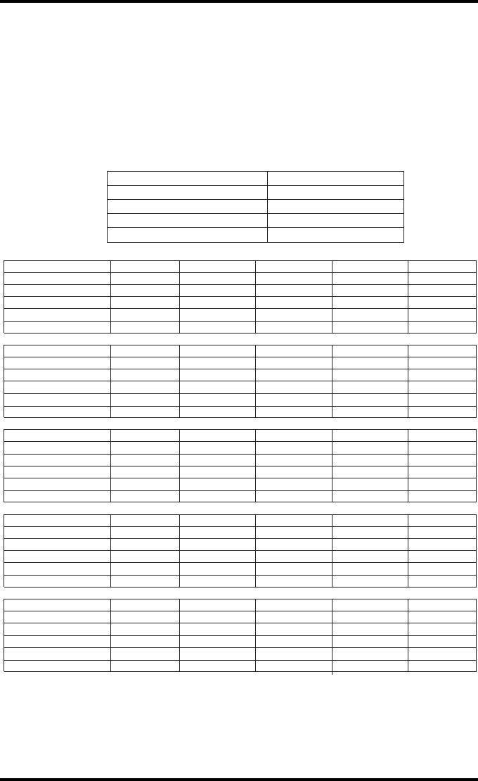
Drystar 5302: Determination of Operating Levels
Chart 1
Imager Type: __________ Serial #: _________________ Date ____________________
Film Type: ____________ Emulsion #: ______________
Densitometer Internal: _________________ (default selection)
External: Type ____________ Serial #: _________________
Day 1 Day 2 Day 3 Day 4 Day 5
Month
Day
Initials
Low Density
Average of 5 Values = operating (aim) level “Low Density”
Mid Density
Average of 5 Values = operating (aim) level "Mid Density"
High Density
Average of 5 Values = operating (aim) level “High Density”
Step 1: Print QC Test images on five consecutive days. Record the optical densities
measurements in the tables below. After five days, average the values to determine
the operating (aim) levels for each of the parameters.
Step 2: Copy the operating (aim) levels to Charts 2A/B ('Daily Density Control Chart')
77
2831A EN 20041201 Quality Control Charts
DRYSTAR 5302 USER MANUAL
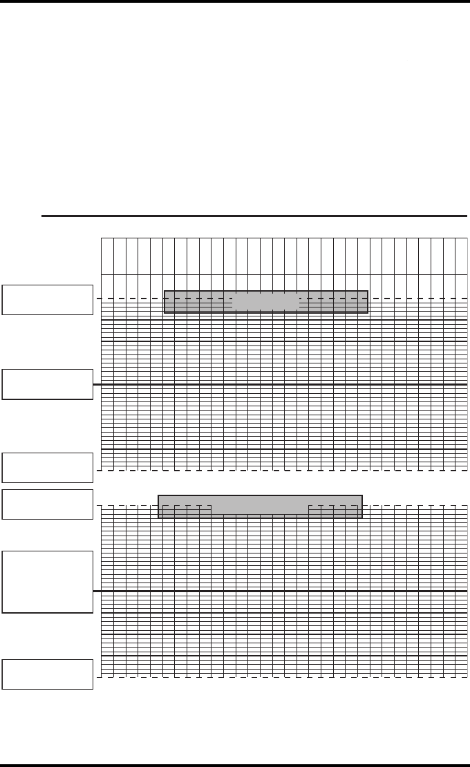
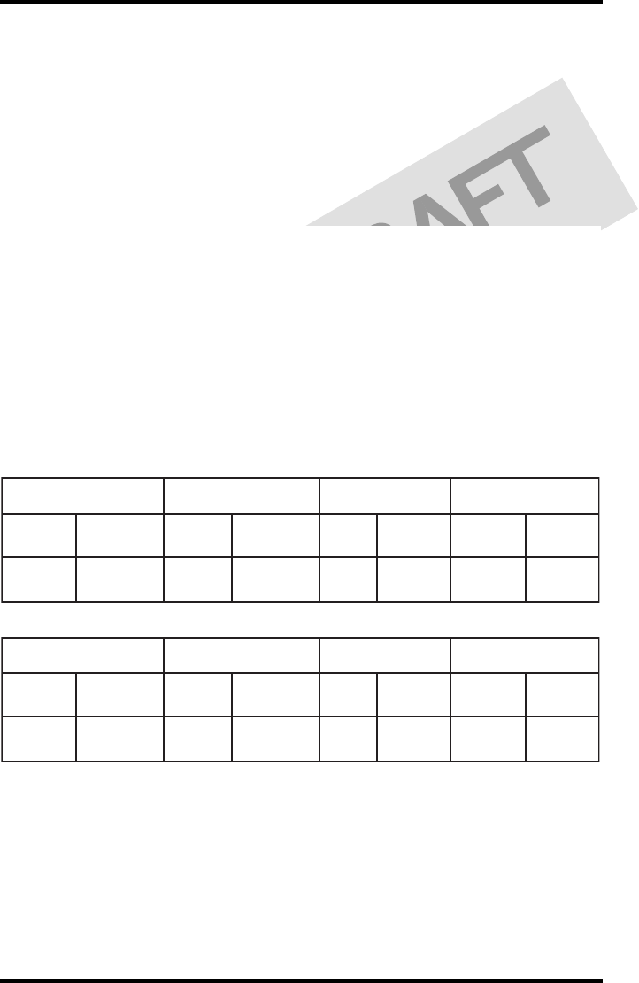
Drystar 5302 Daily Density
Control Chart
Imager Type: __________ Serial #: _____________ Film Type:____________ Emul #:___________
Densitometer Internal: ____________________ (default selection)
External: Type _______________ Serial #:________________
Date:
Initia ls:
Low Density
Mid Density
Upper Control limit =
+0.10
Low Density Aim
Lower Control Limit =
-0.10
Upper Control limit =
+0.20
Mid Density
Aim
(High - Low)
Lower Control Limit =
-0.20
Chart 2A
78 2831A EN 20041201Quality Control Charts
DRYSTAR 5302 USER MANUAL
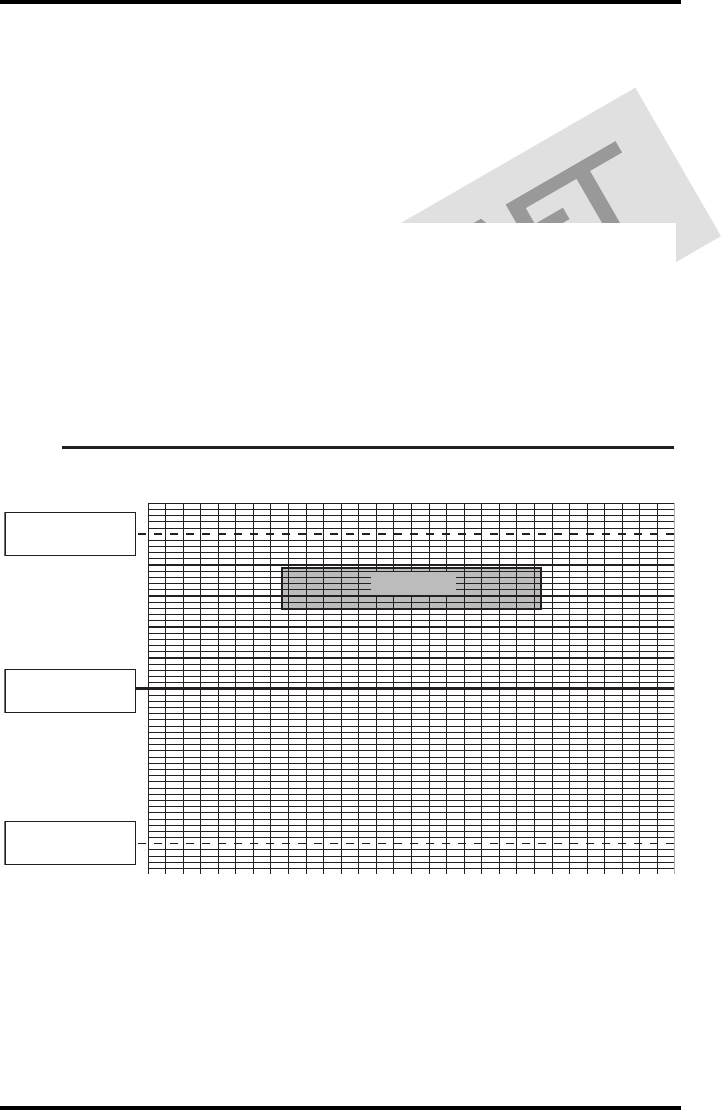
Drystar 5302 Daily Density
Control Chart
Imager
Type: __________ Serial #: _____________ Film Type:____________ Emul #:__________
_
High Density
Upper Control limit =
+0.20
Lower Control Limit =
-0.20
High Density Aim
Chart 2B
Densitometer Internal: ____________________ (default selection)
External: Type _______________ Serial #:________________
79
2831A EN 20041201 Quality Control Charts
DRYSTAR 5302 USER MANUAL
Chart 3
Drystar 5302 Artifacts and Spatial Resolution
Control Chart
Test Frequency: Weekly Drystar 5302 Serial # _____________
Initial Reference Test Date
Initial Reference Artifacts
Initial Reference Dot Visibility
Initial Reference Low Contrast
Month
Day
Artifacts
Visibility of all Dots
Month
Day
Artifacts
Visibility of all Dots
Month
Day
Artifacts
Visibility of all Dots
Month
Day
Artifacts
Visibility of all Dots
Month
Day
Artifacts
Visibility of all Dots
Low Contrast Visibility
Low Contrast Visibility
Low Contrast Visibility
Low Contrast Visibility
Low Contrast Visibility
80 2831A EN 20041201Quality Control Charts
DRYSTAR 5302 USER MANUAL
Chart 4
Drystar 5302 Geometric Consistency
Control Chart
Test Frequency: Annually or as required Drystar 5302 Serial # _____________
_
Reference Dimensions
Date:
Measured Dimensions
Date:
Consistency Aspect Ratio
Aref A: A/Aref A/B
Bref B: B/Bref
Reference Dimensions
Date:
Measured Dimensions
Date:
Consistency Aspect Ratio
Aref A: A/Aref A/B
Bref B: B/Bref

81
2831A EN 20041201 Quality Control Charts
DRYSTAR 5302 USER MANUAL

Printed in Belgium
Published by Agfa-Gevaert N.V., B-2640 Mortsel-Belgium
2831A EN 20041201