Agrident ABR200 ABR200 OEM RFID Reader Module (134.2kHz) User Manual 1 Headline
Agrident Corporation ABR200 OEM RFID Reader Module (134.2kHz) 1 Headline
Agrident >
Contents
- 1. Users Manual
- 2. Users Manual 2
- 3. Users Manual 3
Users Manual 2
Agrident GmbH, Steinklippenstr. 10, D-30890 Barsinghausen
Phone +49 5105 582573-10 - Fax +49 5105 582573-17
ABR200
Integration Manual
F i r m w a r e v 1 . 12 and higher
V14/07/16

14/07/16 Page 2 of 18
ABR200 Integration Manual
© Copyright 2016 by Agrident GmbH
TB
All rights reserved. No part of this publication may be reproduced, stored in a retrieval system, or
transmitted, in any form or by any means, electronic, mechanical, photocopying, recording or
otherwise, without prior written permission of Agrident GmbH.
Agrident GmbH reserves the right to make changes to any and all parts of this documentation
without obligation to notify any person or entity of such changes.
July 2016
Agrident GmbH
Steinklippenstr. 10
30890 Barsinghausen
Germany
Phone +49 (0) 51 05 582573-10
Fax +49 (0) 51 05 582573-17
E-Mail: mail@agrident.com
www.agrident.com

14/07/16 Page 3 of 18
ABR200 Integration Manual
Content
1 Introduction .......................................................................................................... 4
2 Pinout .................................................................................................................. 5
3 Power Supply options .......................................................................................... 6
3.1 Power supply 2.2V – 4.5V ............................................................................ 6
3.2 Power supply 5.0V ....................................................................................... 7
3.3 Power supply from 5V USB .......................................................................... 8
3.4 The ENABLE pin .......................................................................................... 9
4 Current consumption ........................................................................................... 9
4.1 Current consumption for 2.2V – 4.5V input voltage ...................................... 9
4.1.1 RF-on .................................................................................................... 9
4.1.2 RF-off .................................................................................................. 11
4.1.3 Power supply disabled ........................................................................ 11
4.2 Current consumption for 5.0V input voltage ............................................... 11
5 Interface options ................................................................................................ 12
5.1 UART interface ........................................................................................... 12
5.2 USB interface ............................................................................................. 13
6 The GPIOs ........................................................................................................ 13
7 Connecting the antenna .................................................................................... 14
8 Mechanical Dimensions ..................................................................................... 15
9 Mounting the ABR200 ....................................................................................... 15
10 International Approvals .................................................................................. 16
11 Trouble shooting ............................................................................................ 18
14/07/16 Page 4 of 18
ABR200 Integration Manual
1 Introduction
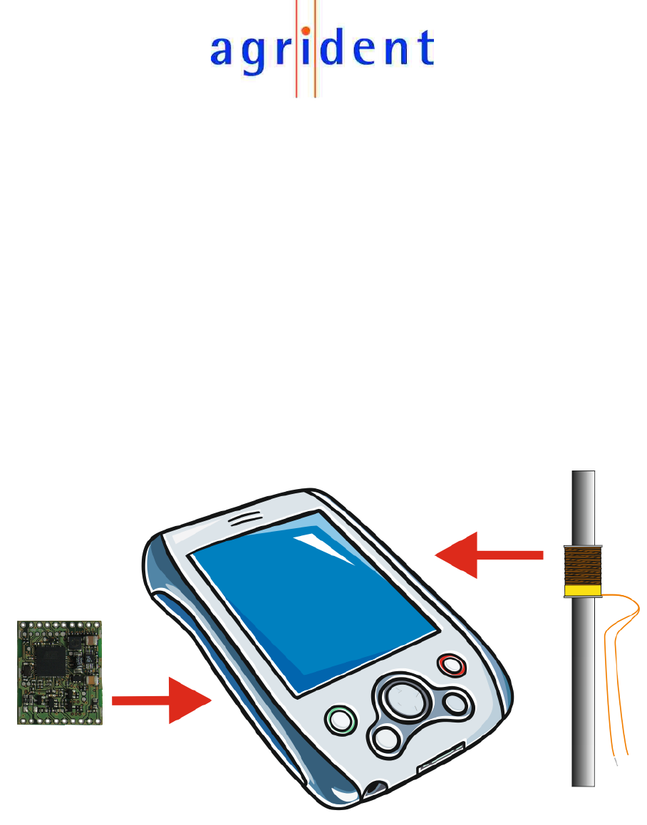
The ABR200 is a low frequency ISO11784/11785 compliant OEM RFID reader module working
on 134.2 KHz. It has been designed for the integration into mobile devices like PDAs. The
ABR200 is not intended to be used as a stationary reader. For stationary readers you should use
a model from the ASR range.
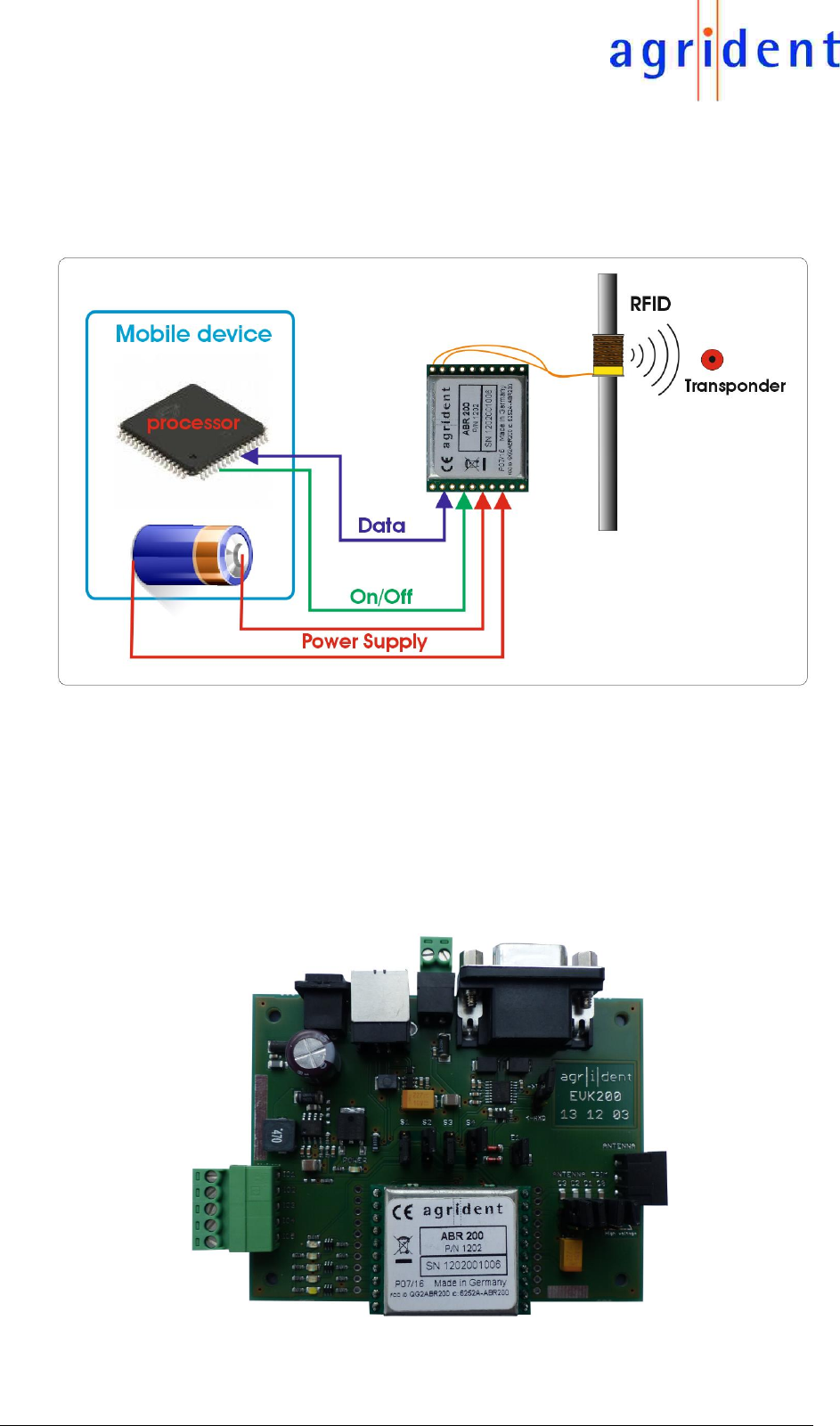
Agrident provides an Evaluation Board in order to make the development of an own software
interface easier for customers. In case of using the ABR200 with the Evaluation Kit, the reader
board is powered by voltage regulators which are supplied with 12 to 24V from a DC power supply.
The reader can be connected to a desktop PC using the RS232 or the USB connector on the
Evaluation Board. However, this setup is different from the use of the reader board in the final
application and has the purpose to evaluate the ABR200 only.
The next picture shows the evaluation board for the ABR200 OEM reader module. For further
details about the evaluation board please see the separate document
“EVK200_Evaluation_Board_for_ABR200_eng.pdf”
EVK200 evaluation board with ABR200
14/07/16 Page 5 of 18
ABR200 Integration Manual
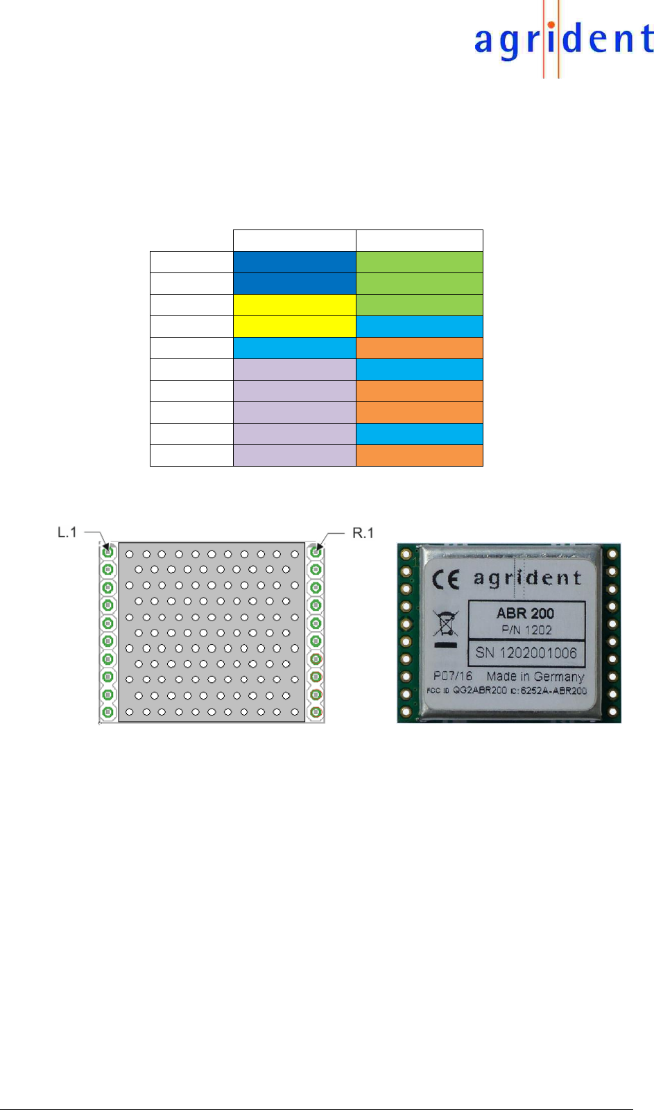
2 Pinout
The ABR200 has one connection terminal on the left side an another one on the right side. Each
terminal has 10 pins and the pitch is 2.54mm. The pin assignment can be found in the table below.
Left
Right
1
USB-DP
Ant-1
2
USB-DM
Ant-2 (CP)
3
UART-RXD
Ant-3 (CP)
4
UART-TXD
GND
5
GND
ENABLE
6
GPIO1
GND
7
GPIO2
5V-IN
8
GPIO3
5V-OUT
9
GPIO4
GND
10
GPIO5
BAT-IN
The orientation of the drawing on the left side matches with the orientation of the picture on the
right side.
14/07/16 Page 6 of 18
ABR200 Integration Manual
3 Power Supply options
The ABR200 is quite flexible concerning the choice of the power supply. The two different options
for supplying the reader module with power are listed below.
2.2V – 4.5V DC (e.g. Lithium battery or 3 NiMH cells in series)
5V from voltage regulator (linear, stabilized, low ripple voltage)
For both options the power supply should be stabilized as good as possible. Ripple and noise
should be reduced to a minimum, otherwise the reading performance might suffer.
If the power source is a switch-mode regulator, the switching frequency of the converter should
be as high as possible. The ABR200 also offers the possibility to synchronize other converters
with a multiple of the RF frequency, which is the best possible scenario for avoiding EMI problems
caused by external switch-mode regulators.
Generally a battery is the most stable power supply – there is no ripple and no noise. The
ABR200s on-board step-up converter does not cause any problems because it runs synchronized
with the RF field as well.
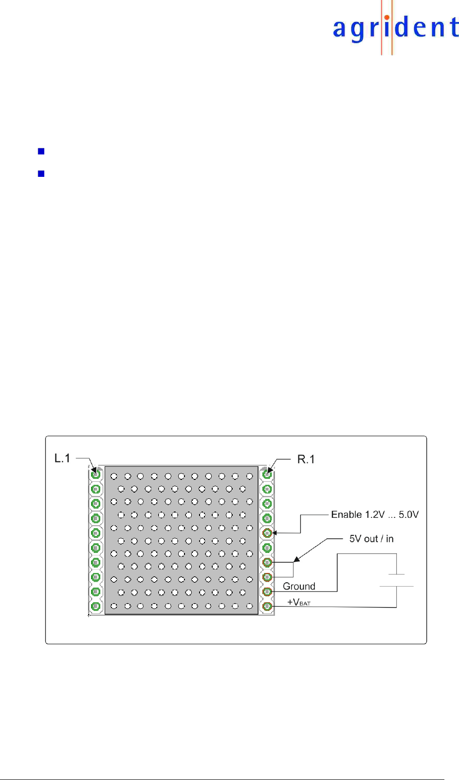
3.1 Power supply 2.2V – 4.5V
If the module should be connected to the battery of a mobile device, the ABR200s on-board boost
converter needs to be used in order to supply certain parts of the module with 5.0 Volts. Therefore
the battery voltage has to be connected to “BAT-IN” of the module. In addition there needs to be
a connection between “5V-OUT” and “5V-IN”.
In order to enable the modules power supply, the “Enable” pin must be driven higher than 1.2V.
The above diagram shows the connection for input voltages between 2.2V and 4.5V.
14/07/16 Page 7 of 18
ABR200 Integration Manual
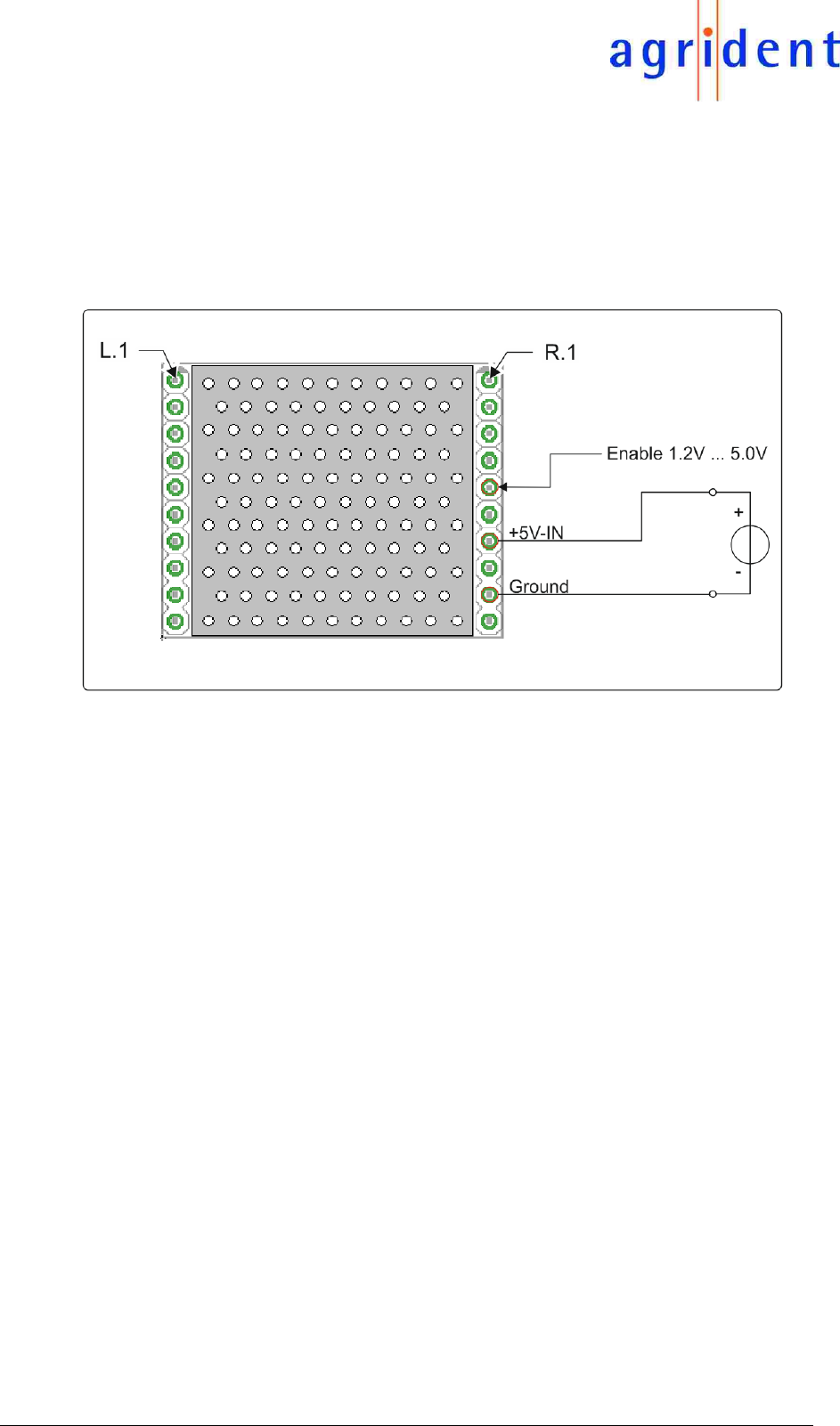
3.2 Power supply 5.0V
In case the ABR200 should be supplied with 5.0V directly, the modules on-board boost converter
is not used. The 5.0V have to be connected to the “5V-IN” pin of the reader. The pins “BAT-IN”
and “5V-OUT” are not used here and should be left open.
For switching on the ABR200s power supply, the “Enable” pin must be driven higher than 1.2V.
The diagram above shows the connection in case of providing 5.0VDC.
14/07/16 Page 8 of 18
ABR200 Integration Manual
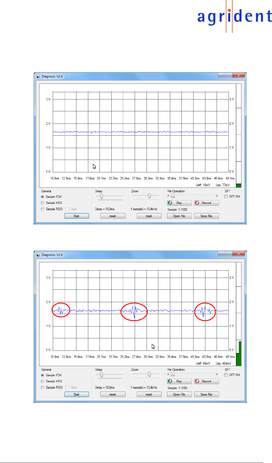
3.3 Power supply from 5V USB
A clean FDX signal is shown below. There is no noise present.
The next screenshot shows the same signal but in this case the module is directly supplied from
the USB port of a computer.
The peaks you can see in the signal are caused by an instable USB voltage. The transmitter
voltage on the module is not stable enough any longer and this causes the peaks in the signal.
The FDX reading range will be reduced in this case, so please try to avoid using USB ports for
supplying the module with power. The USB specification even allows the voltage to drop some
hundred millivolt if a particular amount of current is drawn from the USB port. This is ok for most
USB devices but not for sensitive RFID readers.
14/07/16 Page 9 of 18
ABR200 Integration Manual
3.4 The ENABLE pin
The modules power supply has to be activated via the pin “Enable”. This applies to both power
supply options, 2.2V to 4.5V or 5.0V. This pin must be driven higher than 1.2V - but 5.0V is the
maximum - in order to switch on the ABR200. The maximum allowed voltage for keeping the
reader deactivated is 0.4V.
The Enable line has an on-board pull-down resistor of 1MΩ in order to prevent floating levels.
4 Current consumption
Generally there are three different operating states concerning power consumption:
1. ENABLE is low – the modules power supply is switched off
2. Enable is high and RF is on – the module is operating and RF is on
3. Enable is high and RF is off – the module is running but the field is not activated
4.1 Current consumption for 2.2V – 4.5V input voltage
In case the ABR200 should be powered from a battery, the modules on-board boost converter
has to be used. This converter is able to generate 5.00V from input voltages in the range between
2.2V and 4.5V. The lower the input voltage, the higher the input current.
4.1.1 RF-on
The diagram shows the current drawn from the battery depending on the battery voltage. As you
can see, the current is higher than 700mA at 2.2 Volts input, which corresponds to a power
consumption of more than 1.4W.
Here some detailed values from the specified input voltage range:
Voltage
2.2V
2.5V
3.0V
3.5V
4.0V
4.5V
Current
713mA
592mA
471mA
393mA
337mA
299mA
These values apply if the field is activated. The antenna used for these tests has a very high Q
factor (Agrident 100mm ferrite antenna). If antennas with lower Qs are used, the current
consumption will be lower accordingly.
0
100
200
300
400
500
600
700
800
2,20
2,30
2,40
2,50
2,60
2,70
2,80
2,90
3,00
3,10
3,20
3,30
3,40
3,50
3,60
3,70
3,80
3,90
4,00
4,10
4,20
4,30
4,40
4,50
Input Current in mA
Input Voltage in V
Input Voltage vs Input Current - RF on

14/07/16 Page 10 of 18
ABR200 Integration Manual
The power consumption in this operating mode is shown below:
The power consumption decreases as the input voltage rises. This has to do with the efficiency
of the ABR200s boost converter.
The efficiency of the converter is better at higher input voltages.
On the output side the converter delivers 5.00V. The current in RF-on mode is quite constant with
about 250mA.
1200
1250
1300
1350
1400
1450
1500
1550
1600
1650
1700
2,20
2,30
2,40
2,50
2,60
2,70
2,80
2,90
3,00
3,10
3,20
3,30
3,40
3,50
3,60
3,70
3,80
3,90
4,00
4,10
4,20
4,30
4,40
4,50
Input Power in mW
Input Voltage in V
Input Voltage vs Input Power - RF on
65
70
75
80
85
90
95
100
2,20
2,30
2,40
2,50
2,60
2,70
2,80
2,90
3,00
3,10
3,20
3,30
3,40
3,50
3,60
3,70
3,80
3,90
4,00
4,10
4,20
4,30
4,40
4,50
Efficiency in percent
Input Voltage in V
Input Voltage vs Efficiency

14/07/16 Page 11 of 18
ABR200 Integration Manual
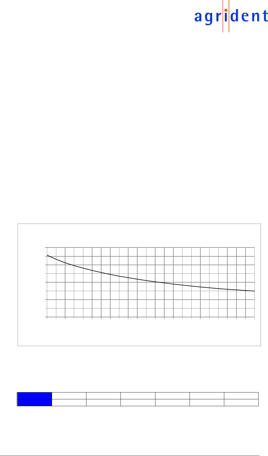
4.1.2 RF-off
When the RF is not activated, the current consumption is much lower.
Anyway, this is not really a “power saving mode” because the input currents are still in a range
between 80mA (at 4.5V) and 175mA (at 2.2V). Thus it is highly recommended to shut down the
ABR200 completely, after a tag has been read.
4.1.3 Power supply disabled
If the ENABLE pin is disabled (ENABLE lower than 0.4V), the input current is smaller than 4µA.
4.2 Current consumption for 5.0V input voltage
When the ENABLE pin is active (voltage between 1.2V and 5.0V) and the RF-field is activated,
the current consumption of the ABR200 is about 250mA.
In case ENABLE is active but the RF-field is switched off, the current consumption is
approximately 70mA.
If the ENABLE pin is low (voltage lower than 0.4V), the current consumption of the module is less
than 1µA.
50
70
90
110
130
150
170
190
210
2,20
2,30
2,40
2,50
2,60
2,70
2,80
2,90
3,00
3,10
3,20
3,30
3,40
3,50
3,60
3,70
3,80
3,90
4,00
4,10
4,20
4,30
4,40
4,50
Input Current in mA
Input Voltage in V
Input Voltage vs Input Current - RF off
14/07/16 Page 12 of 18
ABR200 Integration Manual
5 Interface options
The ABR200 offers two different interface options, a UART interface and USB. Both are working
independently of each other. Thus they could also be used simultaneously.
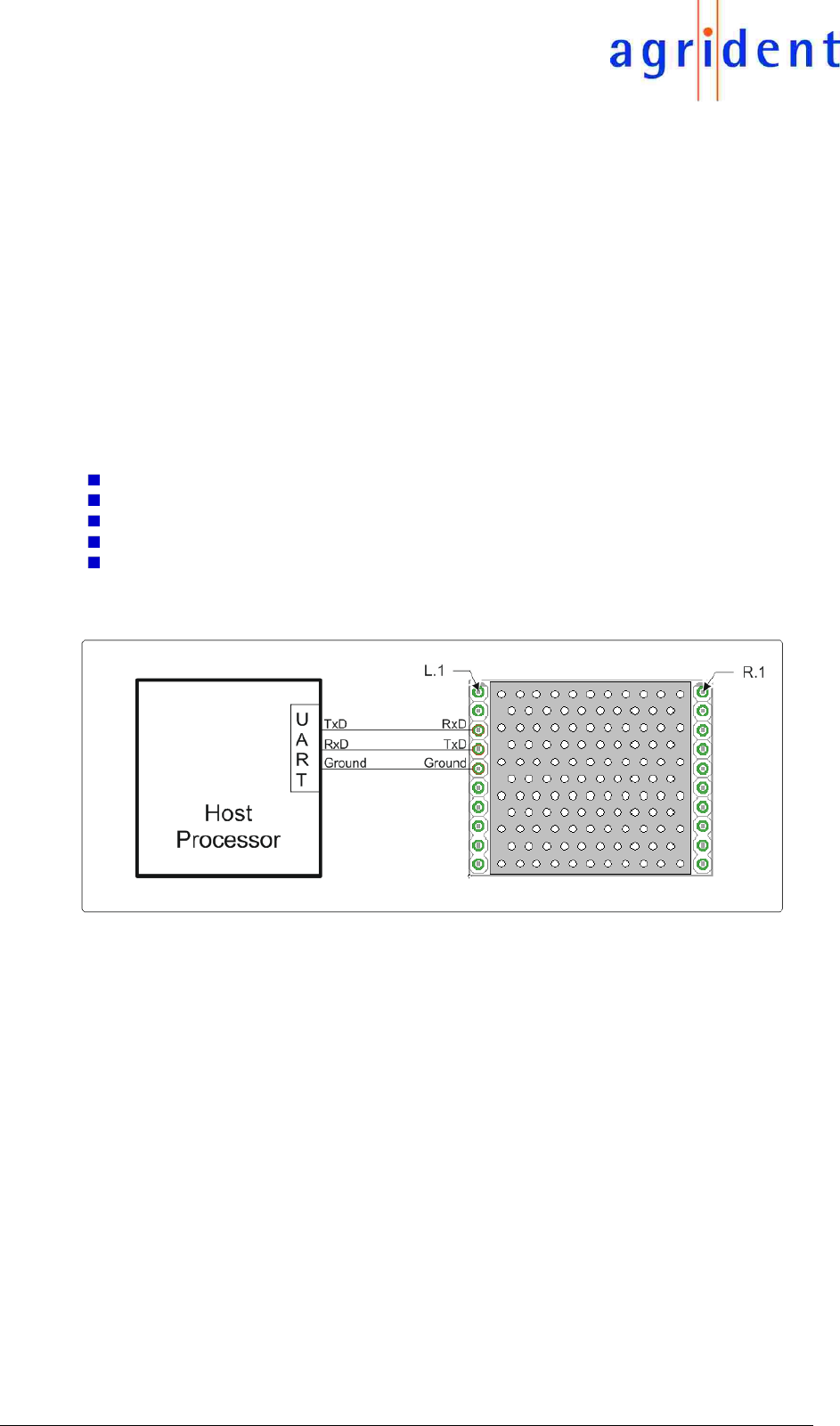
5.1 UART interface
The modules UART interface is working on 3.3V level but the RxD line is 5V tolerant. The TxD
line always transmits at 3.3V and thus level shifters might be required if your UART only works at
5V (i.e.: if your UART is not 3.3V tolerant).
The ABR200 is using the following interface parameters:
9600 Baud to 115200 Baud (configurable, default is 9600)
1 Start Bit
8 Data Bits
No Parity
1 Stop Bit
Please keep in mind that RxD and TxD need to be crossed. Where one device transmits data,
the other device receives data and vice versa.
The TxD line contains a 1KΩ resistor on the ABR200 for current limiting in order to protect the
processor on the reader.
The RxD line contains a pull-up resistor to 3.3V and a diode in series on the ABR200. This ensures
that the RxD level at the ABR200s processor cannot exceed 3.3V – even if another device uses
5V UART level.
Please ensure that the UART of your controller is configured to the same baud rate as the
controller of the ABR200 – otherwise the communication will not work at all.
14/07/16 Page 13 of 18
ABR200 Integration Manual
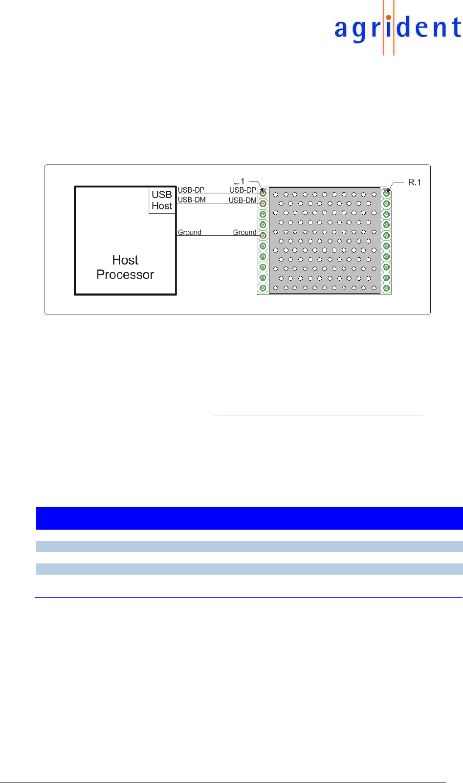
5.2 USB interface
The USB interface of the ABR200 is provided by the processor on the module. The interface uses
USB-CDC (USB Communication Device Class). This is different to the previous reader module
ABR105, which used an FTDI USB chip.
The USB data lines (USB-DP and USB-DM) are using a level of 3.3V as per USB specification.
The diagram above shows how to connect USB on the ABR200.
For USB the configured baud rate does not matter since the devices are negotiating the
communication speed on their own in case of USB.
Agrident can already provide a USB driver installer for Windows desktop computers. Currently
we are working on a solution for a driver for Windows CE and Windows Mobile. A driver for
Android devices should be available here: https://code.google.com/p/usb-serial-for-android/.
6 The GPIOs
There are five GPIOs available on the ABR200. At the moment they are used for the following
purposes:
GPIO
Input /
Output
Function
Description
1
Output
Read
indicates a successful tag read
2
Output
RF-On
indicates that the RF-field is activated
3
Output
Power
indicates that the module power is switched on
4
RFU
RFU
reserved for future use
5
Output
PWM_Out
PWM output for synchronizing external switch-mode
regulators; frequency depends on BAT-IN voltage
All GPIOs have 1KΩ series resistors on the ABR200 for current limiting and thus protecting the
modules processor.
If you want to indicate particular events with LEDs directly from the ABR200 GPIOs, you have to
use additional transistors. The GPIOs themselves cannot drive LEDs.
If you do not use particular GPIOs, please leave those pins open!
14/07/16 Page 14 of 18
ABR200 Integration Manual
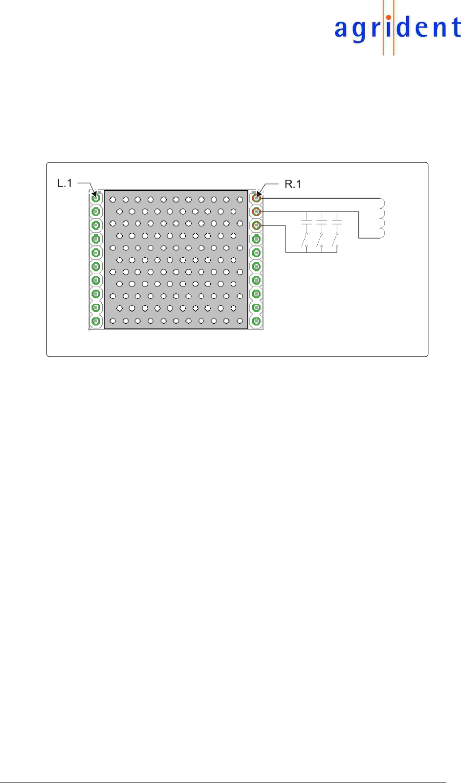
7 Connecting the antenna
The antenna has to be connected between pin 1 and pin 2 of the terminal on the right side.
The ABR200 comes with the on-board resonant circuit capacitors tuned for antennas with an
inductance of 275µH. That means you cannot use antennas with a higher inductance at all. If your
antenna has a smaller inductance than 275µH – maybe because you have an air-coil antenna –
you can add more capacitance between pin 2 and pin 3 as shown in the diagram above. The
capacitors might be soldered to you PCB during production as fixed values or you can set them
using jumpers like shown in this example.
However, tuning the circuit to resonance is always necessary in order to achieve the optimum
reading performance. Please see the antenna tuning manual for further details.
For details concerning the location of antenna and module, please refer to the separate document
“ABR200_AN_Location_Antenna-Module_eng”.
14/07/16 Page 15 of 18
ABR200 Integration Manual
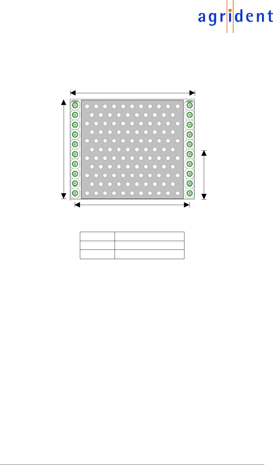
8 Mechanical Dimensions
30mm
32,5mm
26mm
13mm
L.1 R.1
Height
26 mm
Width
32,5 mm
Depth
8 mm
9 Mounting the ABR200
The ABR200 does not need any mounting bolts. It can be soldered to the customers PCB directly.
Since it has two 10-pin connectors, one on the left and the other one on the right side, no
additional fixing is required.

14/07/16 Page 16 of 18
ABR200 Integration Manual
10 International Approvals
FCC and IC digital device limitations
The FCC approval is only valid with the tested antenna “ANT002”. If other antennas should be used, the
complete FCC Part 15 B test procedure has to be repeated!
Any additional antenna may be used with this device, provided that the new antenna is from same type
and has equal or lesser gain than the certified antenna(s). The usage of any new antenna type or higher
gain antenna require either a Class II Permissive Change (add new antennas) by the Grantee (Agrident)
or a complete new authorization under a new FCC ID by the responsible partyfor compliance.
Labeling of end product:
The final end-product must be labeled clearly visible with the following "Contains FCC ID: QG2ABR200"
and "Contains IC: 6252A-ABR200"
If the size of the end-product is larger than 8 x 10 cm, the following FCC Part 15.19 statement shall be
also placed on the device:
This device complies with Part 15 of the FCC Rules.
Operation is subject to the following two conditions:
(1) this device may not cause interference, and
(2) this device must accept any interference, including interference that may cause undesired operation
of the device.
L'utilisation de ce dispositif est autorisée seulement aux deux conditions suivantes:
(1) il ne doit pas produire de brouillage, et
(2) l'utilisateur du dispositif doit être prêt à accepter tout brouillage radioélectrique reçu, même si ce
brouillage est susceptible de compromettre le fonctionnement du dispositif.
If the size of the end product is too small (smaller than 8 x 10 cm) or it is not practicable to place this
statement on the end-product; this statement shall be placed in a prominent location in the instruction
manual or pamphlet supplied to the user or alternatively shall be placed on the container in which the
device is sold.

14/07/16 Page 17 of 18
ABR200 Integration Manual
User Manual of the end-product:
The end user has to be informed that any changes or modifications not expressly approved by the
manufacturer could void the user’s authority to operate this equipment.
FCC §15.105 Information to the user
(a) For a Class A digital device or peripheral, the instructions furnished the user shall include the
following or similar statement, placed in a prominent location in the text of the manual:
NOTE: This equipment has been tested and found to comply with the limits for a Class A digital device,
pursuant to part 15 of the FCC Rules. These limits are designed to provide reasonable protection against
harmful interference when the equipment is operated in a commercial environment. This equipment
generates, uses, and can radiate radio frequency energy and, if not installed and used in accordance
with the instruction manual, may cause harmful interference to radio communications. Operation of this
equipment in a residential area is likely to cause harmful interference in which case the user will be
required to correct the interference at his own expense.
Canadian Radio Emissions Requirement
This Class A digital apparatus complies with Canadian ICES-003. Cet appareil numérique de la classe
A est conforme à la norme NMB-003 du Canada.
CE MARKING
Hereby, Agrident GmbH declares that this equipment, if used according to the instructions, is in
compliance with the essential requirements and other relevant provisions of the RTTE Directive
1999/5/EC. For use in all countries of the EU.
To obtain a copy, contact Agrident GmbH and request the “Declaration of Conformity” document for
Multi-technology readers.
Agrident GmbH
mail@agrident.com
In case of alteration of the product, not agreed to by us, this declaration will lose its validity.
This symbol indicates proof of conformity to applicable European Economic
Community Council directives and harmonized standards published in the official
journal of the European Communities.

14/07/16 Page 18 of 18
ABR200 Integration Manual
11 Trouble shooting
For any problem please contact us:
Agrident GmbH
Steinklippenstr. 10
30890 Barsinghausen
Germany
Telephone +49 5105 582573-10
FAX +49 5105 582573-17
Mail: support@agrident.com