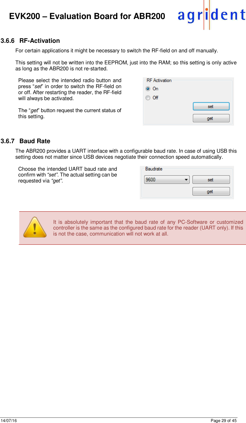
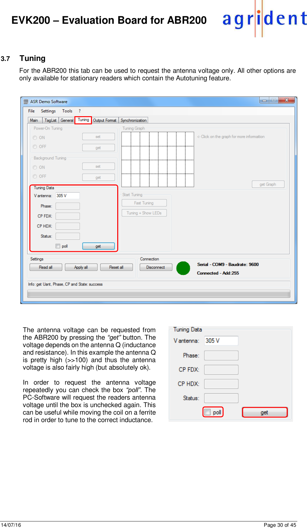
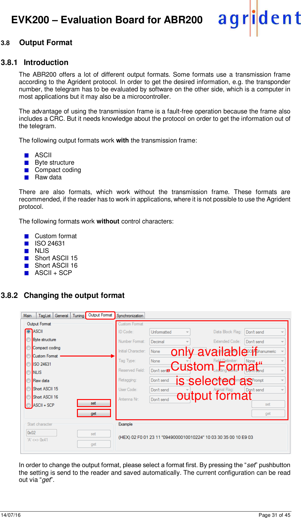
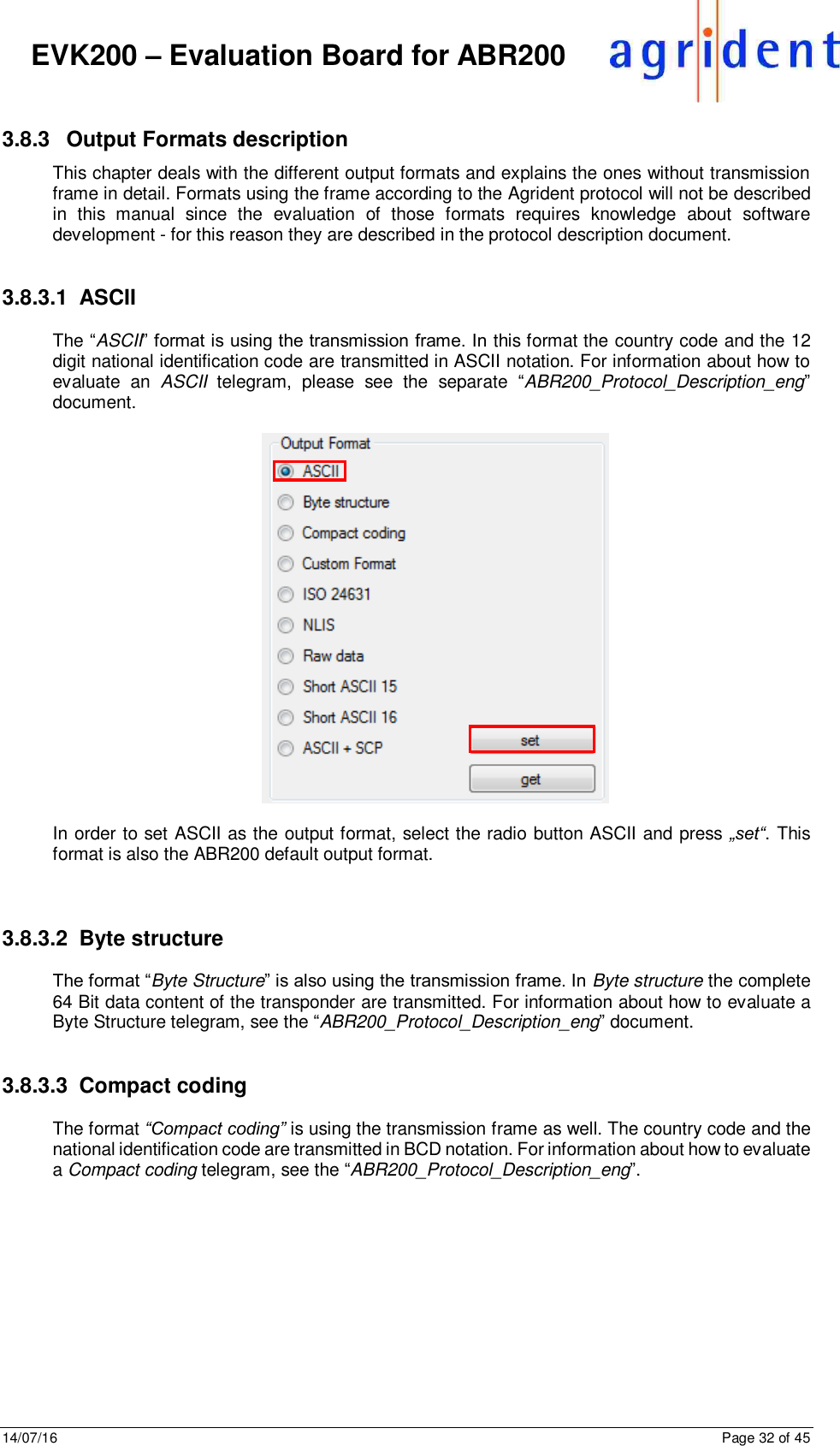
Agrident ABR200 ABR200 OEM RFID Reader Module (134.2kHz) User Manual 1 Headline

Agrident Corporation ABR200 OEM RFID Reader Module (134.2kHz) 1 Headline

Contents

Users Manual 3

  Agrident GmbH, Steinklippenstr. 10, D-30890 Barsinghausen Phone +49 5105 582573-10 - Fax +49 5105 582573-17     EVK200  Evaluation Board for ABR200    A B R 2 0 0   F i r m w a r e   v 1 . 0 0   a n d   h i g h e r  ASR-PC- D e m o   S o f t w a r e   v 1 . 3 9   a n d   h i g h e r    V14/07/16
14/07/16      Page 2 of 45      EVK200 – Evaluation Board for ABR200                                    © Copyright 2016 by Agrident GmbH  TB  All rights reserved. No part of this publication may be reproduced, stored in a retrieval system, or transmitted, in any form or by any means, electronic, mechanical, photocopying, recording or otherwise, without prior written permission of Agrident GmbH.  Agrident GmbH reserves the right to make changes to any and all parts of this documentation without obligation to notify any person or entity of such changes.  July 2016  Agrident GmbH Steinklippenstr. 10 30890 Barsinghausen Germany Phone +49 (0) 51 05 582573-10 Fax     +49 (0) 51 05 582573-17 E-Mail: mail@agrident.com www.agrident.com
14/07/16      Page 3 of 45      EVK200 – Evaluation Board for ABR200 Content  1 Introduction .......................................................................................................... 5 2 The different connectors and jumpers ................................................................. 6 2.1 Jumpers for power supply selection ............................................................. 7 2.1.1 Using 5V from the step-down converter ................................................ 8 2.1.2 Using USB for power supply ................................................................. 8 2.1.3 Using the 3.3V LDO for power supplying the ABR200 .......................... 9 2.1.4 Power supply using the battery connector............................................. 9 2.2 ENABLE jumper ......................................................................................... 10 2.3 Antenna tuning jumpers ............................................................................. 10 2.4 Current jumper ........................................................................................... 10 2.5 Interface connectors ................................................................................... 10 2.5.1 RS232 connector ................................................................................ 10 2.5.2 USB connector .................................................................................... 10 2.6 GPIO connector .......................................................................................... 11 2.7 GPIO LEDs................................................................................................. 11 3 Using the EVK200 with ASR-PC-Demo ............................................................. 12 3.1 Installing the PC-Demo Software ............................................................... 12 3.2 Starting the PC-Demo Software ................................................................. 12 3.3 The Menu Bar............................................................................................. 13 3.3.1 File ...................................................................................................... 13 3.3.2 Settings ............................................................................................... 13 3.3.2.1 Connection ...................................................................................... 13 3.3.2.2 Search connection ........................................................................... 15 3.3.2.3 Log File ............................................................................................ 16 3.3.2.4 Device.............................................................................................. 17 3.3.2.5 Sound .............................................................................................. 18 3.3.3 Tools ................................................................................................... 18 3.3.3.1 Monitor............................................................................................. 18 3.3.3.2 Animal Counter ................................................................................ 19 3.3.3.3 Auto Diagnosis ................................................................................ 21 3.3.3.4 Diagnosis ......................................................................................... 22 3.3.3.5 HDX Spectrum ................................................................................. 22 3.3.3.6 Advanced Tag Read/Write functions ............................................... 22 3.3.4 Help ..................................................................................................... 22 3.3.4.1 Info................................................................................................... 22 3.3.4.2 Update ABR200 ............................................................................... 22
14/07/16      Page 4 of 45      EVK200 – Evaluation Board for ABR200 3.4 The Main-Window of the PC-Demo Software ............................................. 23 3.4.1 Received Tag ...................................................................................... 23 3.4.2 Settings ............................................................................................... 24 3.4.3 Connection .......................................................................................... 24 3.4.4 The “Info” area .................................................................................... 24 3.5 TagList ....................................................................................................... 25 3.6 General Settings ......................................................................................... 26 3.6.1 Serial Number and Firmware Version ................................................. 26 3.6.2 Transponder Types ............................................................................. 27 3.6.3 Operating Mode .................................................................................. 27 3.6.3.1 Delaytime ......................................................................................... 27 3.6.4 Device Address ................................................................................... 28 3.6.5 Timing ................................................................................................. 28 3.6.6 RF-Activation ....................................................................................... 29 3.6.7 Baud Rate ........................................................................................... 29 3.7 Tuning ........................................................................................................ 30 3.8 Output Format ............................................................................................ 31 3.8.1 Introduction ......................................................................................... 31 3.8.2 Changing the output format ................................................................. 31 3.8.3 Output Formats description ................................................................. 32 3.8.3.1 ASCII ............................................................................................... 32 3.8.3.2 Byte structure .................................................................................. 32 3.8.3.3 Compact coding ............................................................................... 32 3.8.3.4 Custom format ................................................................................. 33 3.8.3.5 ISO 24631 ....................................................................................... 36 3.8.3.6 NLIS................................................................................................. 36 3.8.3.7 Raw data ......................................................................................... 37 3.8.3.8 Short ASCII 15 ................................................................................. 37 3.8.3.9 Short ASCII 16 ................................................................................. 37 3.8.3.10 ASCII + SCP .................................................................................... 37 3.9 Synchronization .......................................................................................... 38 3.9.1 Sync. Mode ......................................................................................... 39 3.9.2 Wireless Sync. Level ........................................................................... 40 4 Safety and care ................................................................................................. 44 5 Warranty ............................................................................................................ 44 6 CE MARKING .................................................................................................... 45 7 Trouble shooting ................................................................................................ 45
14/07/16      Page 5 of 45      EVK200 – Evaluation Board for ABR200  1  Introduction In order to make the ABR200 implementation easier for new customers, Agrident provides an Evaluation Kit for this module. This Kit contains:    EVK200 – Evaluation Board for ABR200 OEM reader module    ABR200 – OEM reader module with female connector strips    100mm Ferrite Antenna    12 Volt wall wart with several AC adapters for use in most countries of the world    RS232 cable    USB cable   The following picture shows the EVK200 Evaluation Board with an ABR200 connected:       In order to make the software development easier, Agrident also provides PC-Demo-Software, which was originally developed for Agrident Stationary Readers (ASRs), but also works with the ABR200. Features which are only supported by ASRs, but not by the ABR200, are greyed out and thus not available.  The  PC-Demo-Software  and  the  according  reader  settings,  will  be  explained  later  in  this document.   For technical details about the ABR200 itself, please refer to the ABR200 integration manual.
14/07/16      Page 6 of 45      EVK200 – Evaluation Board for ABR200  2  The different connectors and jumpers The EVK200 has a lot of different connectors for supplying the board with power, for connecting the antenna, interfaces and GPIOs, if required. In addition, there are several jumpers for selecting the input voltage source, for enabling the ABR200s power supply and for adding additional tuning capacitors.          Item Description ST1 DC-Power-Supply, 8V … 24V (provided wall wart has 12V) ST2 USB-Connector (standard B-type) ST4 Battery connector (directly supply ABR200 with 2.2…4.5V DC) ST5 same pinout as ABR200 connector on the left side ST6 same pinout as ABR200 connector on the right side ST7 Connector for GPIOs ST9 Antenna connector ST10 RS232 connector, D-SUB 9-pin, female LEDs GPIO Five LEDs which indicate the current GPIO status S1…S4 Jumpers for selecting the input voltage source for the module E1 Jumper for enabling the module power C0…C3 Jumpers for adding additional capacitance to the antenna resonant circuit     ST1 ST2 ST4 ST10 ST7 ST9 ST5 ST6 S1…S4 E1 C0…C3 LEDs GPIO
14/07/16      Page 7 of 45      EVK200 – Evaluation Board for ABR200  2.1  Jumpers for power supply selection The EVK200 has 4 jumpers (S1 to S4) for selecting different power sources. The table below shows the jumper positions for a particular power supply option.   Jumper  S1  S2  S3  S4  Vin = 5V  down  up  wherever  up  Powered via USB  up  up  wherever  up  Vin = 3,3V (Boost Converter)  wherever  down  down  down  V-BAT (BOOST Converter)  wherever  down  up  down   The following block diagram shows the power supply options on the EVK200 and the functions of the jumpers S1 to S4.    For  supplying  the  reader  module  with  5  volts,  you  may  either  use  the  on-board  step-down converter or 5 volts from USB. If the ABR200s boost converter should be used instead, you can use the 3.3 Volt linear regulator on the EVK200 or an external battery via ST4.
14/07/16      Page 8 of 45      EVK200 – Evaluation Board for ABR200  2.1.1  Using 5V from the step-down converter As shown in the previous diagram, the EVK200 contains a step-down regulator which converts the input voltage (8...24VDC) down to 5VDC. These 5 volts can be used for the ABR200 power supply directly. In this case the ABR200s boost converter is not used.               S1 has to be set down, S2 and S4 up and the position of S3 does not matter.     2.1.2  Using USB for power supply If the ABR200 should be supplied with power from USB (V-BUS), the connection of S1 to S4 has to be done as shown below.               S1,  S2  and  S4  have to  be  set  to  the  upper position and the position of S3 does not matter.   Please note that there is a voltage drop of about 80mV between the USB connector and the +5V-IN pin of the ABR200. This is mainly caused by the USB protection components on the EVK200.  Also have in mind that the FDX reading range can decrease in case of using 5 volts from a USB port. The reason is that the USB voltage is allowed to go down a few hundred millivolts if some hundred milliamps are drawn. Please see the “ABR200_Integration_Manual__eng”  document for further details.
14/07/16      Page 9 of 45      EVK200 – Evaluation Board for ABR200   2.1.3  Using the 3.3V LDO for power supplying the ABR200 In order to simulate operation from a battery, the EVK200 contains an on-board linear regulator which converts 5 volts from the step-down regulator to 3.3 volts. The 3.3 volts can be used for power supplying the ABR200. In this case the ABR200s boost converter will be used because the ABR200 needs 5 volts internally. The connection setup for this power supply version is shown below.              S2,  S3  and  S4  have  to  be  set  to  the  lower position and the position of S1 does not matter.     2.1.4  Power supply using the battery connector You  may  also  connect  a  battery  to  the  EVK200  for  power  supplying  EVK200  and  ABR200. Alternatively a DC source with an adjustable voltage can be used.     Please do NOT apply more than 4.5VDC to the ABR200 (measured at BAT-IN), otherwise the ABR200 will get damaged irreversibly.    It should be considered that there is a voltage drop of up to 470mV between the battery connector ST4 and the BAT-IN pin of the ABR200. This voltage drop depends on the input voltage. So when using the EVK200 in this power supply version it is recommended to measure the input voltage between BAT-IN and Ground at the ABR200 pins.              The position of S1 does not matter. S2 and S4 have to be set to the lower and S3 to the upper position.
14/07/16      Page 10 of 45      EVK200 – Evaluation Board for ABR200  2.2  ENABLE jumper The ENABLE jumper needs to be set for any input voltage option – without setting this jumper, the power supply on the ABR200 is not activated. This pin is connected to the supply voltage for the reader on the EVK200, so either to 5.0V or 2.2 to 4.5V.    2.3  Antenna tuning jumpers The antenna builds a series resonant circuit together with the resonant circuit capacitors which are already on the ABR200. If the inductance of the antenna is lower than 275µH, additional capacitance needs to be added in order to tune the circuit to resonance. There are 4 binary staged capacitors on the EVK200, which might be added or removed via the antenna tuning jumpers. For  further  details  about  this  topic  please  see  the  separate  document “ABR200_antenna_tuning_manual_eng”.   2.4  Current jumper This jumper is used for internal purposes only. It will be removed in later versions of the EVK200.   2.5  Interface connectors The EVK200 provides  two interface connectors, a 9-pole D-SUB connector for RS232 and a standard B-type USB connector. Both interfaces can be used simultaneously.    2.5.1  RS232 connector The RS232 connector is a standard female 9-pole D-SUB connector. Together with the provided RS232 cable it can be connected to a RS232 port of a computer. If the computer does not have a ‘real’ RS232 port anymore, you might use an USB-to-Serial converter for testing this interface. In case of RS232 it is important, that the correct baud rate is selected in the PC Software.   2.5.2  USB connector The USB connector is a standard B-type one. It can be connected to any desktop computer by using  the  provided  USB  cable.  Please  install  the  Agrident  USB  driver  for  Windows  before connecting USB in order to allow an easy installation. If Windows fails to install a driver you need to update the driver manually in the device manager. In case of USB the baud rate setting does not matter since both devices automatically negotiate the connection speed.  The ABR200  appears  with  the  ports friendly  name “Agrident ABR200” in  the Windows device manager:    If you are using another operating system (like Linux), you should look for a ‘standard’ USB-CDC-ACM driver.
14/07/16      Page 11 of 45      EVK200 – Evaluation Board for ABR200  2.6  GPIO connector The  ABR200  provides  5  GPIOs.  Concerning  the  functions  of  the  GPIOs  please  refer  to  the “ABR200_Integration_Manual_eng”  document  or  to  the  next  chapter  “GPIO  LEDs”.  At  the moment the configuration of the GPIOs is fixed.  On the ABR200 the GPIOs just have 1KΩ resistors between the processor and the connection pins. Hence the GPIOs cannot be used to drive an LED, for example. If LEDs should be controlled via the GPIOs, it is necessary to provide additional transistors.  The GPIO connector is directly connected to the GPIO pins of the ABR200.   2.7  GPIO LEDs On the EVK200 there are additional transistors and LEDs for indicating the status for each GPIO. The schematic looks as follows:    If the GPIOs should be connected to LEDs for indicating a particular reader status, a schematic similar to the one above should be used on the customers PCB.  The next table shows the currently used configuration of the GPIOs. This will always remain the factory default configuration for the ABR200.  GPIO LED on EVK200 Function Description 1 green Read indicates a successful tag read 2 red RF-On indicates that the RF-field is activated 3 yellow Power indicates that the module power is switched on 4 blue RFU reserved for future use 5 white PWM_Out PWM output for synchronizing external switch-mode regulators; frequency depends on BAT-IN voltage  At the moment, all GPIOs are configured as outputs.
14/07/16      Page 12 of 45      EVK200 – Evaluation Board for ABR200 3  Using the EVK200 with ASR-PC-Demo Although developed for Agrident Stationary Readers, the PC-Software ASR-PC-Demo can also be used for the ABR200 together with the EVK200. The software can be used for requesting or applying the reader configuration, to show or log received transponders, to request the reader status (voltages and diagnostic functions) or to see the serial communication between the PC and the ABR200 (Serial Monitor).   3.1  Installing the PC-Demo Software Please start the setup file and follow the instructions in order to install the PC-Demo Software.  The Agrident PC-Demo Software is written in Visual Studio and thus requires the Microsoft .NET Framework Version 2.0 or higher.   3.2  Starting the PC-Demo Software  After starting the PC-Demo Software, the following main screen appears.    Since the Software was not able to connect to the ABR200, the default reader “ASR550” is shown. In order to show the correct device, the connection settings might need to be changed according to the desired interface and depending on the comports on your computer.
14/07/16      Page 13 of 45      EVK200 – Evaluation Board for ABR200  3.3  The Menu Bar     The menu bar is located in the upper left corner of the main window.  It  consists  of  the  menu  items  “File”,  “Settings”, “Tools” and “?”.  3.3.1  File The Menu “File” contains only one menu item, “Quit”. This item closes the PC-Demo Software. Alternatively you might also close the program using the corresponding button in the upper right corner of the main window:     3.3.2  Settings The file menu “Settings” contains the menu items “Connection”, “Search Connection”, “Log File” “Device” and “Sound”.      3.3.2.1  Connection  If you press “Connection” an additional window opens. Here you have to select the interface type and the corresponding settings.    The option “TCP” is only available for an ASR with Ethernet or Wi-Fi connectivity.
14/07/16      Page 14 of 45      EVK200 – Evaluation Board for ABR200   Please select the correct Port Name and the correct baud rate. The baud rate is configurable between 9600 and 115200 baud. The configured baud rate of the ABR200 has to match with the selected  baud  rate  of  the  PC-Software  in  case  of  using  the  UART  interface  (RS232  on  the EVK200) – otherwise the communication will not work. Per factory default, the readers baud rate is set to 9600.  In case of having the ABR200/EVK200 connected via USB, you should see the correct port with the friendly name “Agrident ABR200”. The port name itself will vary on your system.      Please ensure that the USB-Driver is installed before connecting an ABR200 via USB for the first time. In case of connecting via USB, the configured baud rate does not matter since both devices automatically negotiate the connection speed.   If the connection was established successfully, the orange circle in the main screen will turn into green. In addition you can see the currently selected port, baud rate, and the network address, the PC-Demo Software will use for communicating with the reader.  You should also see the connected reader type now, here “ABR200”:    The  address  “255”  (0xFF)  means  broadcast.  Please  see  the  ABR200  protocol  description  for further details. In case of the ABR200 different addresses should not be necessary since it does not work on bus systems.       Please keep in mind that each comport can only be accessed by one program. If you want to use other software for communicating with the reader, please close ASR PC-Demo before or at least click on “Disconnect” in the main window.
14/07/16      Page 15 of 45      EVK200 – Evaluation Board for ABR200  3.3.2.2  Search connection  You may also let ASR-PC-Demo detect Agrident readers automatically. Therefore please click on “Search connection” in the “Settings” menu. Another window opens:     Press search in order to start the scan. The software will check all available ports with all possible baud rates. After the search was finished, the result is displayed.      In this example PC software found 2 devices. By having a closer look you can see that it is one and the same device. The first entry was found on COM1, which is an RS232 port in this case. The device was found with a baud rate of 9600. The second entry is the same reader but a different port, which is the connected USB port here. As mentioned before, the baud rate does not matter for USB.  Double click on the corresponding entry in order to connect to the device.
14/07/16      Page 16 of 45      EVK200 – Evaluation Board for ABR200   3.3.2.3  Log File  If you press “Log File” in the “Settings” menu, a small window opens:      Here you can decide whether the PC-Demo Software should create a log file containing the read transponder numbers or not. If the option “On” is selected, the program will create a new log file each time you start the software. The option “Off” causes that no log file will be created. If you decide to save a log file, you also have the possibility to ignore double reads in the log.   As soon as you have activated the  radio  button  “On”  and  you  have  pressed  “Apply”,  a  small explorer window opens which allows you to select a file location for the log file.    Select the desired destination folder and confirm by clicking on “OK”. You may also create a new folder from here.  The content of the tag list looks like this:
14/07/16      Page 17 of 45      EVK200 – Evaluation Board for ABR200 1.  Ignore Known Tags  If this box is checked, the PC-Demo Software will ignore all tags which have already been read since the program was started.   2.  Ignore Double Reads  If the reader transmits one and the same ID again and again, it will be written into the log file only once if this checkbox is activated. If a different ID is read meanwhile, the previous ID will be added to the log again next time it is read. So “Double Reads” only refers to ONE transponder number being read repeatedly.   3.  Save tag with timestamp  It is possible to save the time stamp with each transponder number. In this case the timestamp is taken from the PC clock since the reader does not have an internal clock.    3.3.2.4  Device  This  submenu  allows  choosing  the  reader  product  you  are  using.  The  default  setting  is  the ASR550, but other reader models (incl. ABR200) are supported as well. It makes sense to select the device manually if you want to evaluate diagnosis data “offline”, i.e. with no reader connected. Previous reader models save diagnostic data different from the newer ones, like the ABR200.    Just click on the reader model you want to select. The available menu items and the content of the tabs in the main window will change according to the reader model you have selected. Not all models support all functions and commands.  Please have in mind that ASR-PC-Demo will automatically select the correct reader model as soon as a version request has been answered successfully after a new connecting attempt. That means that your previously selected device might not be selected anymore.
14/07/16      Page 18 of 45      EVK200 – Evaluation Board for ABR200   3.3.2.5  Sound  The PC-Software plays a sound via the speakers if a tag has been read and the speakers are switched on. If you don`t want to hear this sound you can deactivate this function here:     3.3.3  Tools  The  section  Tools  contains  the  submenus  “Monitor”,  “Animal  Counter”,  “Auto  Diagnosis” “Diagnosis”, “HDX Spectrum”, “FDX-ADV Tag Read/Write” and “HDX-ADV Tag Read/Write”.       3.3.3.1  Monitor  The Monitor window shows the complete serial communication between the reader and the PC. This is very useful for software developers in order to verify their own software with the commands the Agrident PC-Demo Software is sending and receiving.    For further details please refer to “ABR200_Protocol_Description_eng”.
14/07/16      Page 19 of 45      EVK200 – Evaluation Board for ABR200  3.3.3.2  Animal Counter  The Animal Counter works similar to the already mentioned log file with the option “Ignore Known Tags” activated. Nevertheless there are some differences.   When you click on this menu item, a “Save As” dialog will open first.    Please choose a folder where you want to save the file containing the read transponders to. The file will be saved as a text file with the default name “Animal Counter” followed by date and time. You might also change this default name, of course.  If  you  press  “Cancel”,  the  Animal  Counter  is  started  anyway  but  no  file  will  be  saved.  This information is also displayed in the Animal Counter window.      If  you  decided  to  save  a  file,  the  selected  path  will  be  displayed.  When  you  are  reading transponders now, the counter is increased as soon as a new, unknown, tag has been read. In addition they will be written into the corresponding text file.
14/07/16      Page 20 of 45      EVK200 – Evaluation Board for ABR200      You may also insert a “new Group” separator. As a result the Animal Counter will be reset to “0” and transponders which were already read in previous groups will be counted again. New Files may also be created from here.  When you open the Animal Counter file with a text editor, like notepad, the file should look similar to this example:    Within the particular groups you can see the EID first and then the counted value within the current group.
14/07/16      Page 21 of 45      EVK200 – Evaluation Board for ABR200  3.3.3.3  Auto Diagnosis  Although this function makes more sense for troubleshooting for stationary readers, you may use  it  with  the  ABR200  as  well.  The  Auto-Diagnosis  automatically  requests  all  possible diagnostic data from the reader and stores them to a previously determined folder on your PC. These data can be used for later analysis.   There are generally two possible reasons for a decreased reading performance:  1.  Wrong  antenna  tuning,  maybe  even  in  combination  with  too  much  metal  close  to  the antenna.  2.  Electromagnetical interference – often referred as “noise”.  The Agrident readers provides powerful diagnosis features for evaluating both, antenna status and noise levels. However, since these features might not be that easy to use “manually” for non-technical people, there is a simple way of getting all these data – the Auto Diagnosis. The collected data are intended to be sent to technical staff for further evaluation.   When  you  click  on  “Auto  Diagnosis”  the following window  will appear. Per default, the Demo  Software  will  request  10  of  each samples – FDX and HDX and the HDX RSSI. Since noise is not static, it always makes sense to save more than 1 sample per channel. You can  press  “Start” in order to  continue  or first increase or decrease the number of samples.         After you have pressed “Start”, a “Browse For –Folder” dialog opens. Here you can select a destination  path  for  the  diagnosis  data.  You also have the possibility to create a new folder.     The  Demo  Software  will  now  request  the reader  status  and  the  selected  number  of diagnosis samples. The data will be saved into the folder you have  selected previously. You can now navigate to that folder and send the complete diagnosis data to technical experts. You  may  also  pack  the  files  using  WinZip, WinRar or a similar tool.
14/07/16      Page 22 of 45      EVK200 – Evaluation Board for ABR200  3.3.3.4  Diagnosis  The  “Diagnosis”  menu  item  is  the  manual  way  of  the  above  described  Auto  Diagnosis.  It  is intended  to be used  by more ‘advanced’  users  only  since it requires  a  little  bit of  background knowledge. It can be used for watching, recording and replaying the signals from the readers receivers. It can be a very powerful tool for troubleshooting. Nevertheless it is a quite complex issue and thus it will not be described here any further, but in a separate manual.   3.3.3.5  HDX Spectrum  This function opens a kind of spectrum analyzer screen. The information are sampled from the HDX receiver of the ABR200 and they can help to identify a particular frequencies which appear as noise. In addition you could also have a look at the frequencies transmitted by an HDX tag.   3.3.3.6  Advanced Tag Read/Write functions  The  ABR200  already  supports  advanced  transponders  according  to  ISO14223.  Beside  Anti-Collision for HDX-Advanced this also includes Read- and Write functions. Please refer to the separate manual “ISO14223-AdvancedTagFunctions_Agrident_eng” for details.   3.3.4  Help The “?” menu contains the menu item “Info” and “Update ABR200”.      3.3.4.1  Info  Here you can see the current version of the PC-Demo software. You may also open the Agrident Website from this info box.      3.3.4.2  Update ABR200  From this menu the Firmware Update can be started manually. But ASR-PC-Demo also notifies the user automatically if a newer Firmware than the current one is available after a successful connection.   The updater is started with the currently used comport and baud rate. These settings can also be selected in the updater but the passed parameters from the PC-Demo should be correct.
14/07/16      Page 23 of 45      EVK200 – Evaluation Board for ABR200  3.4  The Main-Window of the PC-Demo Software    After the Demo Software was started and the connection to the reader was successful, you should see a screen similar to the one above. The main screen consists of the sections “Received Tag”, “Settings”, “Connection” and an area for status messages (Info) which also contains a progress bar. Beside that you can see which type of reader is connected to the PC Demo Software – here an ABR200.   3.4.1  Received Tag This section is used for displaying the IDs which have been sent by the reader. Each time a tag number is received, the background color of the text fields turns into green for a short time.    4-digit Country Code as defined per ISO 11784/11785 12-digit National Identification Code as defined per ISO 11784/11785 Transponder Type, if supported by the selected output format (FDX-B or HDX) Indication of whether the read transponder is an animal tag or not, if supported by the selected output format (can be TRUE or FALSE)  In  this  case  the  output  format  was  “Byte  structure”.  This  format  does  not  only  provide  the information if the tag is an animal tag or not, but also the other “Advanced ISO information” like “User  Information”  (also  called  Species  Code),  “Reserved  Zone”,  “Retagging  Counter”  or  the “Data Block Flag”.
14/07/16      Page 24 of 45      EVK200 – Evaluation Board for ABR200 3.4.2  Settings These buttons  are available  within  all  tabs  of the  main window.  “Read all” requests  all  reader settings in one step, independently of the tab which is currently active. “Apply all” is similar but will send all settings to the ABR200. “Reset all” will set the reader back to factory default values.         Please note that there is no additional “Save” command necessary for storing the configuration to the reader’s non-volatile memory like it had to be done for the previous OEM reader module ABR105.    3.4.3  Connection As already mentioned earlier in this manual, the “Connection” area indicates the serial connection status of the reader. There are three possible conditions:     The port is closed. You have to click “Connect” in  order  to open the port. Please make sure that  port  name  and  baud  rate  are  correct, otherwise  please  change  these  settings  via “Connection” in the file menu “Settings”.    The PC-Demo Software opened the port and tries to connect to the reader. If this does not succeed  after  some  seconds,  please  check your port settings again.   The  program  could  connect  to  an  Agrident reader  successfully.  The  complete  reader settings (from all tabs) are requested and filled in into the corresponding fields automatically.    3.4.4  The “Info” area This section is used for displaying status messages. In addition there is a status bar indicating progress of the current operation.    In this example the request for all reader settings (“Read all”) was answered by the reader successfully.     As we can see here, the command could not be sent to the  reader  successfully,  i.e.  there  was  no  response received from the reader.  This works similar for all other “set” or “get” operations.
14/07/16      Page 25 of 45      EVK200 – Evaluation Board for ABR200  3.5  TagList The tab “TagList” can be used to view a list of read transponders. You can see which tag has been read how many times. If supported by the configured output format, you can also see the tag type. The antenna number is only important if a stationary reader with antenna multiplexer is used.    The button “clear” empties the list. In this example some HDX-ADVANCED tags have been read as well. Reading HDX-ADV tags requires to activate this tag type first!      All of the above shown HDX tags are HDX-ADV tags. The reason why two of them are shown as “HDX” is that there was not data collision happening. In this case these tags behave as standard HDX tags.
14/07/16      Page 26 of 45      EVK200 – Evaluation Board for ABR200 3.6  General Settings    The “General” tab provides access to several different reader settings, which are responsible for the common operating characteristics.    3.6.1  Serial Number and Firmware Version  You can request the 6-digit Serial Number of the reader, which corresponds with the ID Label on the printed circuit board. You may  also  request  the  currently  used Firmware version.      The “get” buttons only request these particular settings while “Read all”  will  request  all  reader  settings.  The  “set”  buttons  function accordingly.
14/07/16      Page 27 of 45      EVK200 – Evaluation Board for ABR200  3.6.2  Transponder Types  Since the ABR200 is a reader according to the ISO11784/11785 regulations, it can read FDX-B and HDX transponders. Anyway, if you do not want  to  read  either  of  both technologies, you might deactivate it here. In addition HDX-ADV and EM4002 (H4002) tags can be read if the corresponding boxes are checked.    3.6.3  Operating Mode Unlike the stationary readers, the ABR200 has only one operating mode: “Continuous ID output”. In this operating mode the reader has its RF-field activated permanently and the ID is transmitted via UART and USB automatically and repeatedly. Because there is only this operating mode for the ABR200, the other modes are greyed out.     The repeated transmission of one and the same ID can be controlled via the setting “Delaytime”. Please refer to chapter 3.6.3.1 for details.  If necessary, the RF-field can be switched on or off by commands.   3.6.3.1  Delaytime  The “Delaytime” is the period the reader waits before sending one and the same ID repeatedly. If the ASR decodes a different ID, the Delaytime does not matter. The Delaytime is configurable in milliseconds.  Value Hex Value Decimal Description 00 0 Maximum  Delaytime;  One  and  the  same  ID  will  not  be transmitted again until another transponder was read.  01 50ms Default value; The same ID will be transmitted again after 50ms, if the transponder was read again.  02 100ms The same ID will  be transmitted again  after  100ms, if the transponder was read again.  … … Values in 50ms steps are possible  FE 12700ms Largest possible numeric value  FF 12750ms No Delaytime. The ID will be transmitted repeatedly directly after reading.
14/07/16      Page 28 of 45      EVK200 – Evaluation Board for ABR200  3.6.4  Device Address  Although  it  does  not  really  make  sense  to change the device address for the ABR200 (point-to-point connections only, no bus), it is possible. The default device address is 0x01.    3.6.5  Timing In order to allow the ABR200 to read both transponder technologies – FDX-B and HDX – the reader has to switch on and off the field for certain periods. This is called timing. Per default, the reader uses the variable timing as defined per ISO11784/11785. In this timing the reader decides about length of the field on / field off periods on its own. The results of those decisions depend on the presence of a corresponding transponder.      The following patterns are possible using the variable timing:  FDX tag present? HDX tag present? Field-On time Field-Off time No No 50ms 4ms Yes No 50…100ms 4ms No Yes 50ms 20ms Yes Yes 50…100ms 20ms  A field-on period followed by a field-off period can be called slot or cycle. In the variable timing, every 10th cycle is 50:20 milliseconds fixed. This should allow wireless synchronizing handheld readers to read an HDX tag at least once a second.  However, there might be applications where a fixed timing could be the better choice. Therefore the ABR200 offers 3 different timings with a fixed length for the slots: 50:20, 70:20 or 100:20. Independently of the setting, every 10th cycle will be 50:20 again. If the stationary reader would not do that, no handheld close to it would be able to read an HDX tag at all in case of using 70:20 or 100:20.    Select  the  timing  you  want  to  use  for your  application  and  press  the  “set” button. After a reset to factory defaults, the ABR200 will always use the variable timing again.  The  “get”  button  requests  the  currently configured setting from the reader.
14/07/16      Page 29 of 45      EVK200 – Evaluation Board for ABR200  3.6.6  RF-Activation For certain applications it might be necessary to switch the RF-field on and off manually.   This setting will not be written into the EEPROM, just into the RAM; so this setting is only active as long as the ABR200 is not re-started.  Please select the intended radio button and press “set” in order to switch the RF-field on or off. After restarting the reader, the RF-field will always be activated.  The “get” button request the current status of this setting.    3.6.7  Baud Rate The ABR200 provides a UART interface with a configurable baud rate. In case of using USB this setting does not matter since USB devices negotiate their connection speed automatically.  Choose the intended UART baud rate and confirm with “set”. The actual setting can be requested via “get”.        It  is absolutely important that  the baud  rate  of  any PC-Software  or  customized controller is the same as the configured baud rate for the reader (UART only). If this is not the case, communication will not work at all.
14/07/16      Page 30 of 45      EVK200 – Evaluation Board for ABR200   3.7  Tuning For the ABR200 this tab can be used to request the antenna voltage only. All other options are only available for stationary readers which contain the Autotuning feature.        The  antenna voltage  can  be  requested from the ABR200 by pressing the “get” button. The voltage depends on the antenna Q (inductance and resistance). In this example the antenna Q is  pretty  high  (>>100)  and  thus  the  antenna voltage is also fairly high (but absolutely ok).  In  order  to  request  the  antenna  voltage repeatedly you can check the box “poll”. The PC-Software will request the readers antenna voltage until the box is unchecked again. This can be useful while moving the coil on a ferrite rod in order to tune to the correct inductance.
14/07/16      Page 31 of 45      EVK200 – Evaluation Board for ABR200 3.8  Output Format  3.8.1  Introduction The ABR200 offers a lot of different output formats. Some formats use a  transmission frame according to the Agrident protocol. In order to get the desired information, e.g. the transponder number, the telegram has to be evaluated by software on the other side, which is a computer in most applications but it may also be a microcontroller.  The advantage of using the transmission frame is a fault-free operation because the frame also includes a CRC. But it needs knowledge about the protocol on order to get the information out of the telegram.  The following output formats work with the transmission frame:    ASCII   Byte structure   Compact coding   Raw data  There  are  also  formats,  which  work  without  the  transmission  frame.  These  formats  are recommended, if the reader has to work in applications, where it is not possible to use the Agrident protocol.  The following formats work without control characters:    Custom format   ISO 24631   NLIS   Short ASCII 15   Short ASCII 16   ASCII + SCP   3.8.2  Changing the output format    In order to change the output format, please select a format first. By pressing the “set” pushbutton the setting is send to the reader and saved automatically. The current configuration can be read out via “get”.   only available if „Custom Format“ is selected as output format
14/07/16      Page 32 of 45      EVK200 – Evaluation Board for ABR200  3.8.3  Output Formats description This chapter deals with the different output formats and explains the ones without transmission frame in detail. Formats using the frame according to the Agrident protocol will not be described in  this  manual  since  the  evaluation  of  those  formats  requires  knowledge  about  software development - for this reason they are described in the protocol description document.    3.8.3.1  ASCII  The “ASCII” format is using the transmission frame. In this format the country code and the 12 digit national identification code are transmitted in ASCII notation. For information about how to evaluate  an  ASCII  telegram,  please  see  the  separate  “ABR200_Protocol_Description_eng” document.      In order to set ASCII as the output format, select the radio button ASCII and press „set“. This format is also the ABR200 default output format.    3.8.3.2  Byte structure  The format “Byte Structure” is also using the transmission frame. In Byte structure the complete 64 Bit data content of the transponder are transmitted. For information about how to evaluate a Byte Structure telegram, see the “ABR200_Protocol_Description_eng” document.   3.8.3.3  Compact coding  The format “Compact coding” is using the transmission frame as well. The country code and the national identification code are transmitted in BCD notation. For information about how to evaluate a Compact coding telegram, see the “ABR200_Protocol_Description_eng”.
14/07/16      Page 33 of 45      EVK200 – Evaluation Board for ABR200  3.8.3.4  Custom format  The “Custom format” is like a construction kit, the user can put together the output string according to the requirements of his application. It does not use the transmission frame.  In order to gain access to the Custom Format panel, you have to choose Custom Format as the output format first. For any other output format, the Custom Format selection panel is greyed out.     In the above screen you can see that the default value for “ID Code” is “Unformatted”. In this case the reader transmits the 64 Bit transponder “raw data” in hexadecimal notation. Below the Custom Format configuration box you can see a preview of your selected output format.  If the “ID Code” is set  to “Formatted”, it is possible to select or deselect initial characters and additional information, to choose delimiters or to cut leading zeros. Select your desired Custom Format and press the corresponding “set” button.  The different options and their settings are described below.   ID Code FORMATTED allows the selection and formatting of the individual ID code items UNFORMATTED sends 16 digits of unformatted hexadecimal transponder data   Number Format DECIMAL decimal (0-9) number representation HEXADECIMAL hexadecimal (0-9 and A-F) number representation
14/07/16      Page 34 of 45      EVK200 – Evaluation Board for ABR200  Initial Character  The Initial Character is a single ID code string identifier character, sent as the first identification code character.  # (ALLFLEX STYLE) sends "#" as first ID code string character L (TIRIS LINE MODE) sends "L" as first ID code string character X (TIRIS EXECUTE MODE) sends "X" as the first ID code string character G (TIRIS GATE MODE) sends "G" as first ID code string character Self defined * None no ID code string initial character is sent *…  If  you  choose  “Self  defined”,  any  ASCII  character  can  be  selected.  The  character  can  be entered in hex notation (0x..) or as the number of the designated ASCII character. It is also possible to enter the ASCII character directly. An example:  You want the ASCII character “A” as initial character.  Enter “A” into the corresponding field    ASCII character  or  Enter “0x41” into the corresponding field   Hex value of the ASCII character A    Tag Type ID  Transponder type identification character   ALLFLEX STYLE FDX-B-ISO transponders F HDX-ISO transponders H HDX-Industrial R/O transponders R HDX-Industrial R/W transponders W  TIRIS STYLE FDX-B-ISO transponders A HDX-ISO transponders A HDX-Industrial R/O transponders R HDX-Industrial R/W transponders W  None no tag type identification character is sent   Reserved Field Don´t send does not send the reserved field data Send does send the reserved field data   Retagging Counter Don´t send does not send the retagging counter  Send does send the retagging counter
14/07/16      Page 35 of 45      EVK200 – Evaluation Board for ABR200  User Code Don´t send does not send the user code Send does send the user code  Data Block Flag Don´t send does not send the data block flag Send does send the data block flag  Extended Code  “Extended Code” is the country or manufacturer code.  It consists of 4 digits. Manufacturer codes have decimal values larger or equal to 900, country codes have decimal values lower than 900.  Don´t send does not send the extended code Send does send the extended code  Country Code ISO ALPHANUMERIC If  the  extended  code  is  a  country  code,  it  will  be  sent  as  an alphanumeric  representation,  e.g.  “DEU”  for  Germany.  If  the extended code is a manufacturer code its decimal value will be sent in numeric representation.  NUMERIC   The  decimal value  of  the  extended  code  will  be sent  in  numeric representation, e.g. “276” for Germany.  Field Delimiter  The field delimiter separates identification code items. Between the initial character and the ID-tag type identification character no delimiter is sent!  Tabulator a tabulator separates ID code items Semicolon a semicolon separates ID code items Comma a comma ID code items Space a space separates ID code items None No separation  Leading Zeroes  Example Don’t Send does not send leading zeroes 980 123456 Send   does send leading zeroes 980 000000123456  Command Prompt  Enables/Disables transmission of the command prompt „>" as a trailer of messages. If you work with terminal software like Hyperterminal, it provides a better overview of the communication process.  No prompt disables transmission of the command prompt Send prompt enables transmission of the command prompt  Animal Flag Don´t send does not send the animal flag Send does send the animal flag
14/07/16      Page 36 of 45      EVK200 – Evaluation Board for ABR200  3.8.3.5  ISO 24631  The  “ISO  24631”  format  contains  additional  information,  like  animal  flag,  retagging  counter, species code and so on. The last characters of the telegram will be <CR> (0x0D) <LF> (0x0A).      Transmission of information by a communication link, excluding the time stamp option, as defined per ISO 24631.       The  ISO  24631 format  allows  defining  the  start  character  of  the telegram.  Enter  the  desired character in decimal or hexadecimal notation and press the corresponding “set” pushbutton. The factory default start character is “0x02”.   3.8.3.6  NLIS  If “NLIS” is activated, 16 digits will be transmitted in ASCII notation without frame. The leading zero of the country code is not transmitted. The NLIS format is the same like Short ASCII 15 but with a space as delimiter between country code and ID. The last characters of the telegram will be <CR> (0x0D) <LF> (0x0A).   ID0 ID1 ID2 ID3 ID4 ID5 ID6 ID7 ID8 ID9 ‘9’ ‘8’ ‘4’ ‘ ’ ‘0’ ‘1’ ‘0’ ‘9’ ‘0’ ‘0’ ID10 ID11 ID12 ID13 ID14 ID15 CR LF   ‘3’ ‘1’ ‘6’ ‘3’ ‘5’ ‘8’ 0x0D 0x0A    ID0...ID15  ‘984 010900316358’ CR  0x0D LF  0x0A
14/07/16      Page 37 of 45      EVK200 – Evaluation Board for ABR200  3.8.3.7  Raw data  The format “Raw data” uses the transmission frame. In this format, the complete content of the transponder  (for  FDX-B  including  header  and  control  bits)  is  transmitted.  In  case  of  HDX transponders Byte structure and Raw data output format is similar because HDX tags do not contain additional bits. For information about how to evaluate a Raw data telegram, please see the “ABR200_Protocol_Description_eng”.   3.8.3.8  Short ASCII 15  If “Short ASCII” is activated, 15 digits (3 digits country code + 12 digits ID) will be transmitted in ASCII notation without frame. The leading zero is not transmitted. The last characters of  the telegram are <CR> (0x0D) <LF> (0x0A).    ID0 ID1 ID2 ID3 ID4 ID5 ID6 ID7 ID8 ID9 ‘9’ ‘8’ ‘4’ ‘0’ ‘1’ ‘0’ ‘9’ ‘0’ ‘0’ '3' ID10 ID11 ID12 ID13 ID14 CR LF    ‘1’ ‘6’ ‘3’ ‘5’ ‘8’ 0x0D 0x0A     ID0...ID14  ‘0984010900316358’ CR  0x0D LF  0x0A   3.8.3.9  Short ASCII 16 Short  ASCII16  is  the  same  as  Short  ASCII15  but  the  leading  zero  in  the  country  code  is transmitted. The last characters of the telegram are <CR> (0x0D) <LF> (0x0A).   ID0 ID1 ID2 ID3 ID4 ID5 ID6 ID7 ID8 ID9 ‘0’ ‘9’ ‘8’ ‘4’ ‘0’ ‘1’ ‘0’ ‘9’ ‘0’ ‘0’ ID10 ID11 ID12 ID13 ID14 ID15 CR LF   ‘3’ ‘1’ ‘6’ ‘3’ ‘5’ ‘8’ 0x0D 0x0A    ID0...ID15  ‘0984010900316358’ CR  0x0D LF  0x0A    3.8.3.10  ASCII + SCP  The format “ASCII  +  SCP” does  not  use a transmission frame. Only  the last 10 digits of the national identification code are transmitted.    ID0 ID1 ID2 ID3 ID4 ID5 ID6 ID7 ID8 ID9 ‘0’ ‘9’ ‘0’ ‘0’ ‘3’ ‘1’ ‘6’ ‘3’ ‘5’ ‘8’ CR LF         0x0D 0x0A          ID0...ID9  ‘0900316358’ CR  0x0D LF  0x0A  The last characters of the telegram are <CR> (0x0D) <LF> (0x0A).
14/07/16      Page 38 of 45      EVK200 – Evaluation Board for ABR200  3.9  Synchronization If two or more readers operate in close vicinity to each other, they have to be synchronized.    The example on the  right shows  that the  readers  are  not  synchronized.  If reader 1 tries to read an HDX tag when the field is switched off, it might fail in this  scenario.  The  reason  is  that readers  2  and  3  have  their  fields activated at this time; that means they transmit  on  the  same  frequency  like the HDX trans-ponder – but with much more  power.  If  the  unsynchronized readers are too close to each other (up to  50  meter,  depending  on  antenna size and orientation), they will not be able  to  pick  up  an  HDX  transponder signal – at least not at the maximum possible distance.     The solution for this problem is “Synchronization”. There are particular mechanisms which ensure that the timing of several readers is strictly synchronized.     In  this  example  the  readers  are synchronized. The field on / off cycles are synchronous. There is always one Sync.  Master,  all  other  readers  are Sync. Slaves.   Since  all  readers  have  the  HDX-listening period at the same time, there is  no  more  interference  and  the transponder signal can be picked up.
14/07/16      Page 39 of 45      EVK200 – Evaluation Board for ABR200  Please open the “Synchronization” tab in order to set up the ABR200 for synchronizing with other readers.     Per default, synchronization is disabled. If Wireless Sync. is not activated in the Sync. Mode section, the advanced Wireless Sync. settings are greyed out and thus not available. The options for wired synchronization are also not selectable because the ABR200 is supposed to operate in mobile devices which do not allow to use cables for synchronizing.       There  is  no  particular  Sync.  Master  –  the  readers  decide independently which one is the Master. If the Master reader stops working, another reader will automatically take over the role of the Sync. Master.     3.9.1  Sync. Mode  There are only two different settings possible:  1.  no Sync.  2.  Wireless Sync.
14/07/16      Page 40 of 45      EVK200 – Evaluation Board for ABR200   1.  No Sync. Mode  Using this setting, which is also the factory default value, the ABR200 will not ‘listen’ to any other readers but will independently decide when to activate and deactivate the RF-field. As long as there are no other readers in close proximity, this setting can be used without any problems.         All Agrident portable readers support “Wireless Synchronization”. This  is  necessary  because  you  cannot  use  Sync.  cables  for portable  readers.  In  order  to  allow  the  Wireless  Sync.  for Handheld  devices  working  as  good  as  possible,  it  is  highly recommended to set the  stationary readers to a fixed timing of 50:20ms –  if  there  are  no  other  reasons  which  would  speak against  that.  The  latest  Agrident  stationary  readers  support Wireless Sync. as well as reading FDX tags within 50ms.    2.  Wireless Sync. Mode  In order to use Wireless Sync. you have to activate this option as Sync. Mode setting first. More details about this option will be explained in chapter 3.9.2.    3.9.2  Wireless Sync. Level  How does Wireless Synchonization work?  During the HDX listening period, the ABR200 is able to evaluate the so called RSSI level. RSSI means: Received Signal Strength Indication. You might already know this term from other radio technologies like Wi-Fi. If another reader is activating its RF-field during the HDX listening period of the reader we are currently looking at, the ABR200 will take this ‘rising edge’ in the RSSI as the reason also to activate its own RF-field immediately.   Although the integrated diagnosis function was not explained in detail in this manual, we will have a  look  at  some  RSSI  samples.  If  necessary,  please  refer  to  the “Agrident_Integrated_Diagnosis_Function_Manual_eng” first.
14/07/16      Page 41 of 45      EVK200 – Evaluation Board for ABR200    In a “noise-free” environment, the RSSI should be 500mV or lower like in the screenshot above.    The following sample shows the rising edge in the RSSI, caused by another reader which just activated its field.    What the ABR200 requires in order to make the correct decision is a particular Sync. Level. The level needs to be set higher than the highest peak in the ‘background noise’. So in our example it would be okay to set the Sync. Level to approximately 500mV. You might also set it higher but then you decrease the sensitivity of Wireless Sync. A level of about 2 Volts or higher would make no sense at all since the ‘other’ reader does not exceed the 2 Volts in the ABR200s RSSI.       If  you  want  to  select  a  Sync  level  manually,  your  value  should always be only a bit higher than the maximum background noise. This  ensures  that  the  ABR200  will  also  synchronize  to  readers which  are further apart. The Sync. Level is comparable  with  the “Trigger Level” of an oscilloscope.    At this time the own RF-field is switched off. This is the start of the HDX listening period. Sync. Level needs to be set
14/07/16      Page 42 of 45      EVK200 – Evaluation Board for ABR200   In the next example the ‘other’ reader seems to be further apart because the signal rise in the RSSI is smaller.    If you would select a Sync. Level of 1.3 Volts or even higher in this case, Wireless Sync. would never work because the signal, caused by the other reader, never reaches this level.  Fortunately  the  ABR200  also  offers  an  automatic  Sync.  Level  detection  which  works  really reliable. In this case the reader always evaluates the changes in the background noise and tries to set the lowest possible Sync. Level on its own. For the automatic Sync. level detection the level is also continuously update, which is not possible if the level is chosen manually.    If you do not know exactly what you are doing with the manual configuration,  we highly  recommend  using  the  automatic  Sync. Level detection in order to avoid unnecessary malfunction of the Sync. mechanism.         Use the slide control for selecting a Sync. Level and press “set” in order to send the setting to the reader. You can request the current setting via “get”.   If the slide control is on the left side, Wireless Sync. is off. The slide control on the very right side means Sync. Level auto detection. All values in between are valid voltages for the Sync. level.
14/07/16      Page 43 of 45      EVK200 – Evaluation Board for ABR200     Wireless Sync. can only work with a fixed timing. The ABR200 can either use 50:20ms, 70:20ms or 100:20ms.    The Sync. timing is set via Timing in the General tab as well.  Since the variable timing is not allowed in case of using Wireless Sync., the ABR200 will use a fixed timing of 50:20ms if variable timing is set in combination with Wireless Sync..  So if Wireless Sync. is activated, the settings in the Timing section work as follows:       The ABR200 will use a fixed timing of 50ms field activation and 20ms field off.         The ABR200 will use a fixed timing of 50ms field activation and 20ms field off.        The ABR200 will use a fixed timing of 70ms field  activation  and  20ms  field  off.  The exception  is  every  10th  cycle,  which  is 50:20ms.         The  ABR200  will  use  a  fixed  timing  of 100ms field activation and 20ms field off. The exception is every 10th cycle, which is 50:20ms.
14/07/16      Page 44 of 45      EVK200 – Evaluation Board for ABR200  4  Safety and care The manufacturer accepts no liability for damage resulting from improper use or use not consistent with that described in these operating instructions.    The ABR200/EVK200 contains no parts that can be repaired by the user. For this reason the Reader Electronic may only be repaired by authorized customer service personnel.    In both operation and storage of the reader please  secure to comply with  the environment conditions specified in the technical data.   Any modification to the ABR200/EVK200 will render the warranty null and void.   5  Warranty The manufacturer of the ABR200/EVK200 will provide a warranty of   12 months  from the day the device is shipped and subject to the following conditions:  a.  Without submission of proof of purchase no warranty can be given. b.  In the event that defects are detected the manufacturer is entitled to choose between up to two  attempts  at  repair  or  supplying a  replacement device on  one  occasion. The  warranty period for the repaired item or for a replacement item is 3 months but will always extend to the end of the original warranty period. No further claims can be entertained, especially claims for compensation for consequential losses. This exclusion of liability does not apply to claims made on the basis of the Product Liability Act. c.  Warranty claims cannot be entertained unless the Agrident system was installed properly and used properly and for the purpose intended.  No warranty obligations exist in particular when:  1.  Damage is attributable to improper use of the device, to a incorrect connection or incorrect operator action; 2.  The  device  was  not  cared  for  and  maintained  in  accordance  with  the  manufacturer's recommendations and this is the cause of the damage; 3.  The damage is due to any modification to the device; 4.  The damage is due to force majeure, for example, lightning strike; 5.  The damage is due to wear resulting from overstressing mechanical parts.
14/07/16      Page 45 of 45      EVK200 – Evaluation Board for ABR200  6  CE MARKING Hereby, Agrident BV declares that this equipment, if used according to the instructions, is in compliance with the essential requirements and other relevant provisions of the RTTE Directive 1999/5/EC. For use in all countries of the EU.   To obtain a copy, contact Agrident BV and request the “Declaration of Conformity” document for Multi-technology readers.  Agrident BV  mail@agrident.com  In case of alteration of the product, not agreed to by us, this declaration will lose its validity.  This  symbol  indicates  proof  of  conformity  to  applicable  European  Economic Community Council directives and harmonized standards published in the official journal of the European Communities.                           7  Trouble shooting  For any problem please contact us:  Agrident GmbH Steinklippenstr. 10 30890 Barsinghausen Germany  Telephone   +49 5105 582573-10 FAX  +49 5105 582573-17 e-mail   support@agrident.com

Navigation menu