Airespace WNAP1200B 2.4 GHz 802.11 Access Point User Manual Airespace AP 802 11a Radio Quick Install Guide
Airespace 2.4 GHz 802.11 Access Point Airespace AP 802 11a Radio Quick Install Guide
Contents
- 1. Install Guide
- 2. Users Manual
Install Guide
3/18/03 Copyright © 2003, Airespace, Inc. All Rights Reserved.
Airespace AP 802.11a Radio Card Quick Installation Guide
Airespace AP 802.11a Radio Card Quick Instal-
lation Guide System Release 1.1
Overview
This guide is designed to provide professional installers with the information
needed to install an Airespace AP 802.11a Radio Card in a 1200B Airespace
Access Point to create a 1200AB Airespace Access Point.
WARNING: DO NOT attempt to install the Airespace AP 802.11a
Radio Card if you are not a professional installer certified by Airespace,
Inc. to perform this installation. If you perform this installation without
Airespace, Inc. certification, you will void the FCC certification for the
resulting 1200AB Airespace AP, and will be in violation of FCC regula-
tions. (See FCC Statements for Airespace AP in the Airespace Product
Guide for additional information.)
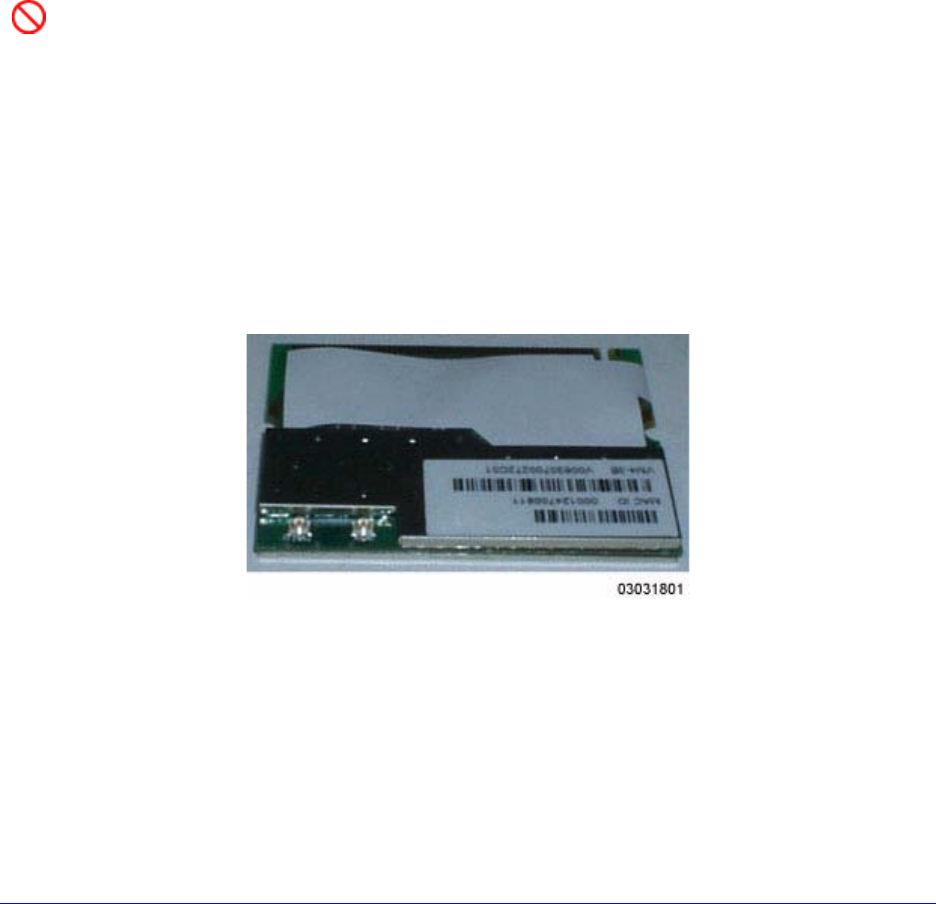
The following figure shows a typical 802.11a Radio Card.
Figure - Typical Airespace AP 802.11a Radio Card
Continue with Step 1: Collecting Required Tools and Materials.

3/18/03 Step 1: Collecting Required Tools and Materials 2
Step 1: Collecting Required Tools and Materials
Step 1: Collecting Required Tools and Materials
•Airespace AP 802.11a Radio Card kit -- includes 802.11a Radio Card
and replacement FCC label.
•Correct Security Torx screwdriver (exact size to be determined).
•1200B Airespace Access Point to be upgraded to a 1200AB Access
Point. See Airespace AP Models for more information.
•A power source for the Airespace AP:
-Either an Airespace AP External Power Converter, or
-A connection from an 802.3af-compliant Power Over Ethernet
device.
•A separate WiFi-approved device (such as Air Magnet) used to detect
and verify 802.11a transmissions.
Continue with Step 2: Setting up an ESD Workspace.

3/18/03 Step 2: Setting up an ESD Workspace 3
Step 2: Setting up an ESD Workspace
Step 2: Setting up an ESD Workspace
You need an Electrostatic Discharge (ESD) workspace to complete this instal-
lation. Because the 802.11a Radio Card is very sensitive to electrostatic
discharge, you can destroy it by not following ESD procedures.
Caution: DO NOT attempt to install the Airespace AP 802.11a Radio
Card if you do not have an ESD workplace, or you may destroy the
802.11a Radio Card.
Continue with Step 3: Opening the Airespace AP Case.
3/18/03 Step 3: Opening the Airespace AP Case 4
Step 3: Opening the Airespace AP Case
Step 3: Opening the Airespace AP Case
•If necessary, remove any brackets and/or mounting bases from the
bottom of the Airespace AP.
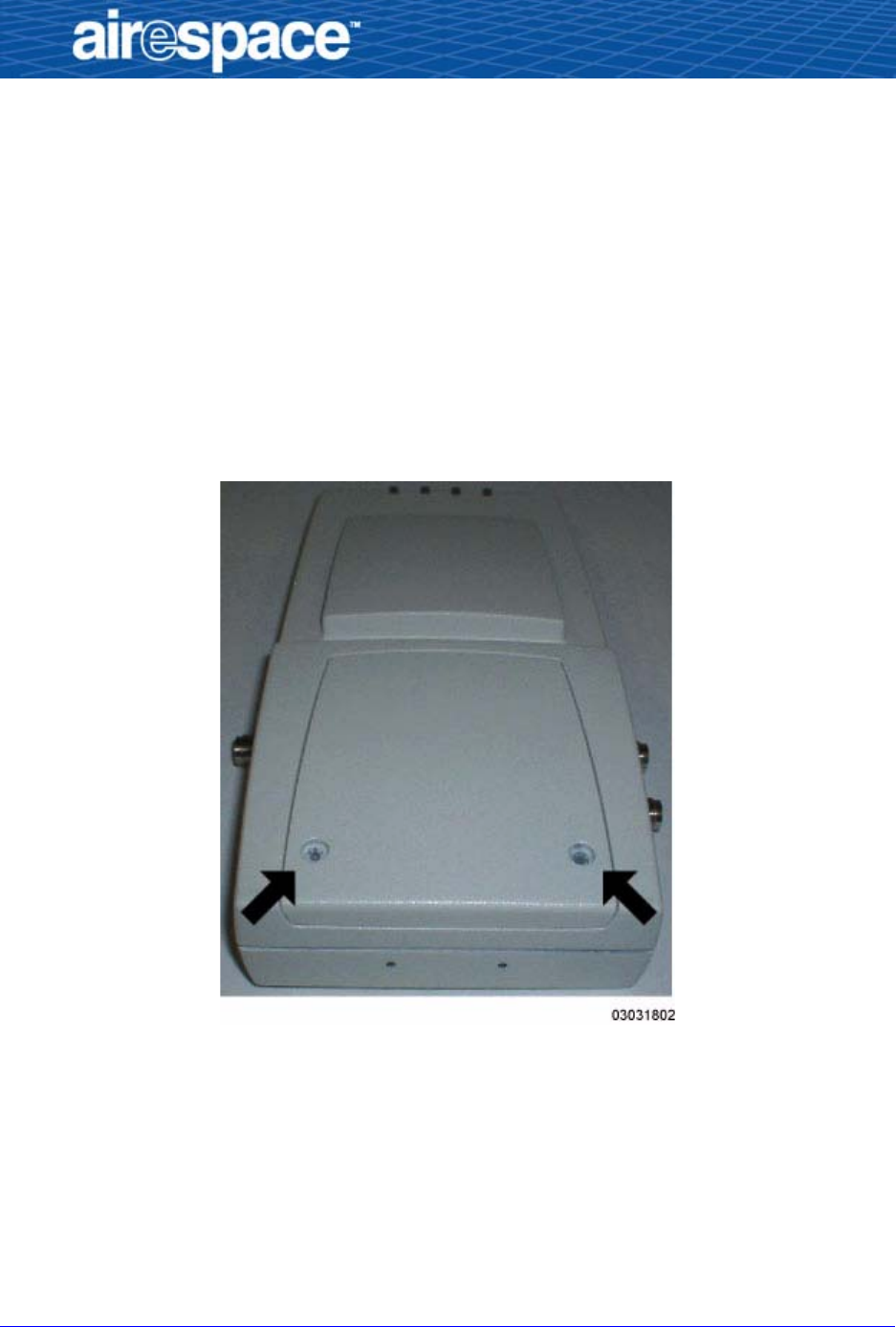
•Use your Security Torx screwdriver to remove the two screws securing
the Airespace AP door.
Save the two screws for later reuse.
Figure - Airespace AP Screw Locations
3/18/03 Step 3: Opening the Airespace AP Case 5
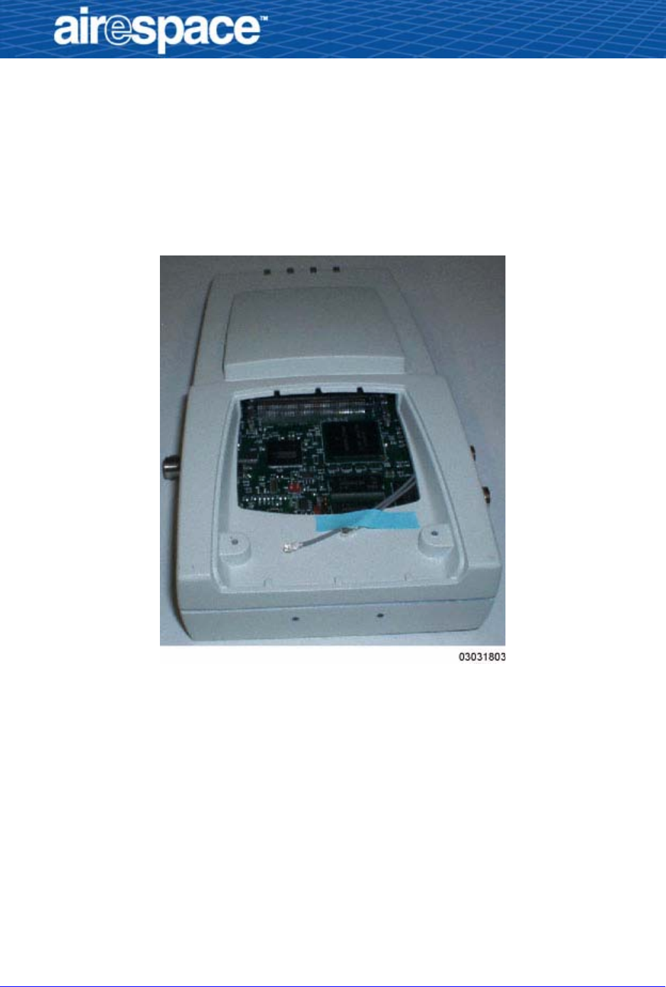
•Remove the Airespace AP door.
Note that the 1200B has two RF cable ends taped to the inside of the
case, one labeled “1” and the other labeled “2”.
•Remove the tape to release the two RF cable ends.
Figure - Airespace AP with Door Removed
Continue with Step 4: Installing the 802.11a Radio Card.
3/18/03 Step 4: Installing the 802.11a Radio Card 6
Step 4: Installing the 802.11a Radio Card
Step 4: Installing the 802.11a Radio Card
•Take a moment to ensure that your ESD workspace is secure: wrist
strap, desktop mat, floormat and/or heel strap properly grounded.
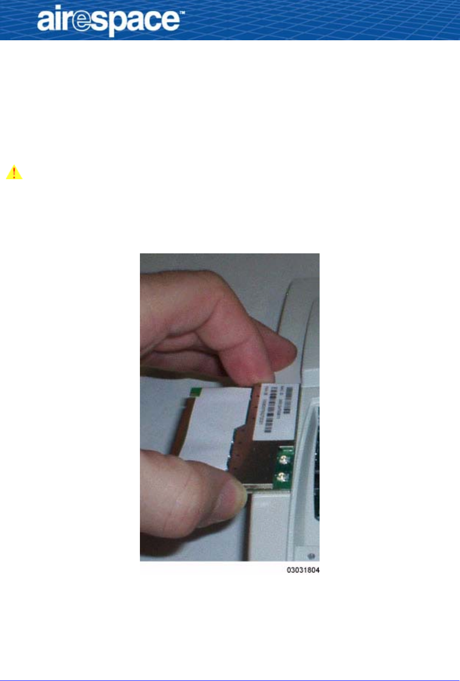
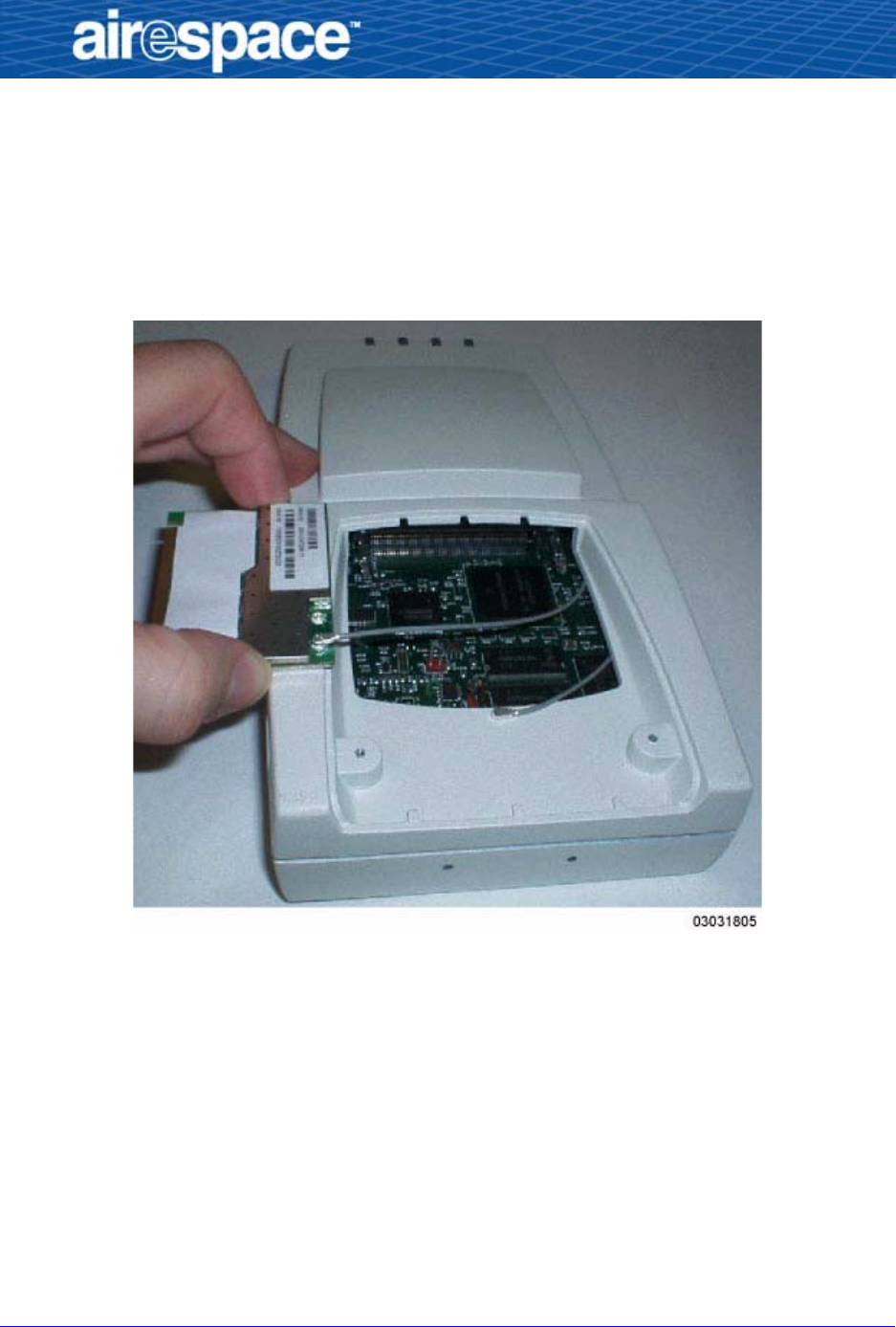
Caution: Even if you are working at an ESD workspace, you can still
damage the 802.11a Radio Card. Make sure you pick up the 802.11a
Radio Card by the edges as shown in the following figure, and do not
touch the connector fingers.
Figure - Holding the 802.11 Radio Card by the Edges
•Remove the 802.11a Radio Card from its kit and position the card on
the edge of the Airespace AP case as shown in the previous figure.
3/18/03 Step 4: Installing the 802.11a Radio Card 7
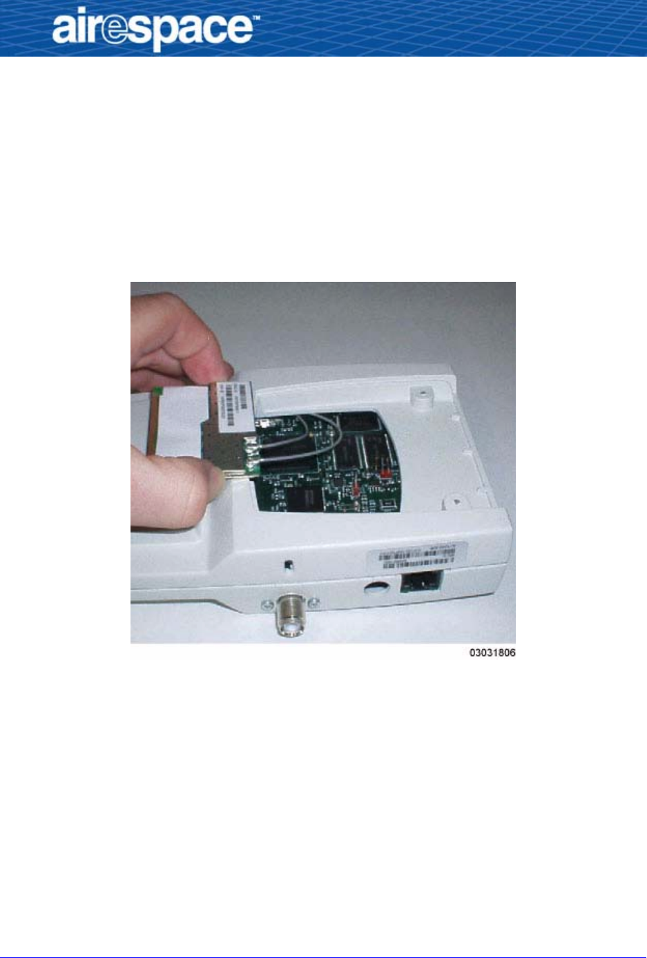
•While holding the 802.11a Radio Card on the edge of the Airespace AP,
gently snap the RF cable labeled “1” onto the RF connector nearest the
corner of the 802.11a Radio Card.
When you are done, the assembly should look as follows:
Figure - 802.11a Radio Card with RF Cable "1" Attached
3/18/03 Step 4: Installing the 802.11a Radio Card 8
•Rotate the AP 802.11a Radio Card and position the card on the middle
of the Airespace AP case as shown in the next figure.
•While holding the 802.11a Radio Card on the middle of the Airespace
AP, gently snap the RF cable labeled “2” onto the RF connector nearest
the center of the 802.11a Radio Card.
•When you are done, the assembly should look as follows:
Figure - 802.11a Radio Card with RF Cables "1" and "2" Attached
3/18/03 Step 4: Installing the 802.11a Radio Card 9
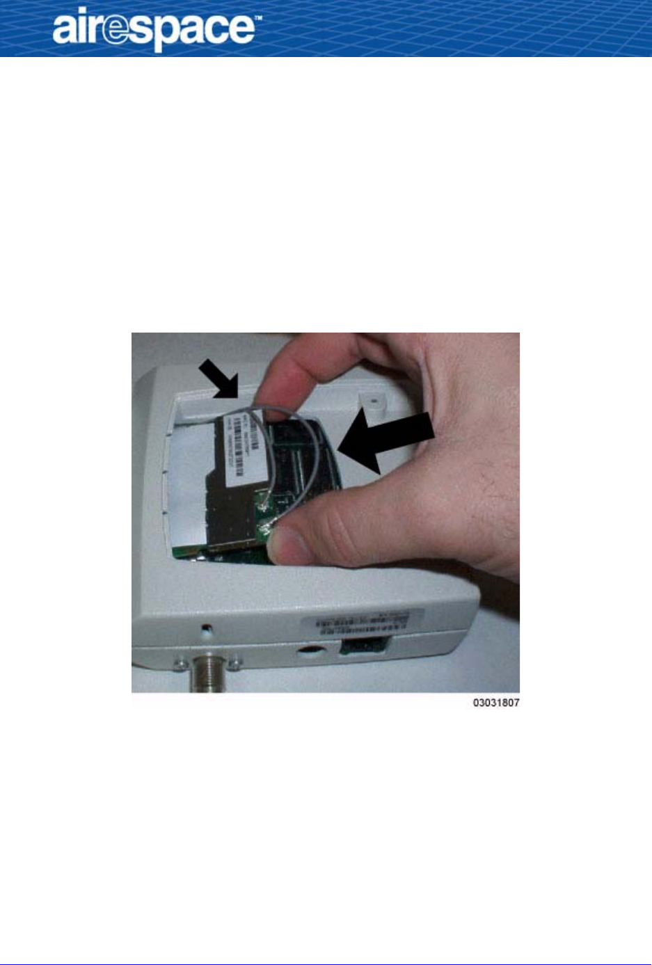
•Carefully rotate the 802.11a Radio Card as shown in the following
figure.
•Make sure the RF cables are not pinched under the 802.11a Radio Card
(small arrow).
•Position the 802.11a Radio Card against its mating connector at a
shallow angle (large arrow).
•Gently press the 802.11a Radio Card all the way into its mating
connector until it bottoms out in the connector (large arrow).
Figure - Positioning the 802.11a Radio Card in the Airespace AP Case
3/18/03 Step 4: Installing the 802.11a Radio Card 10
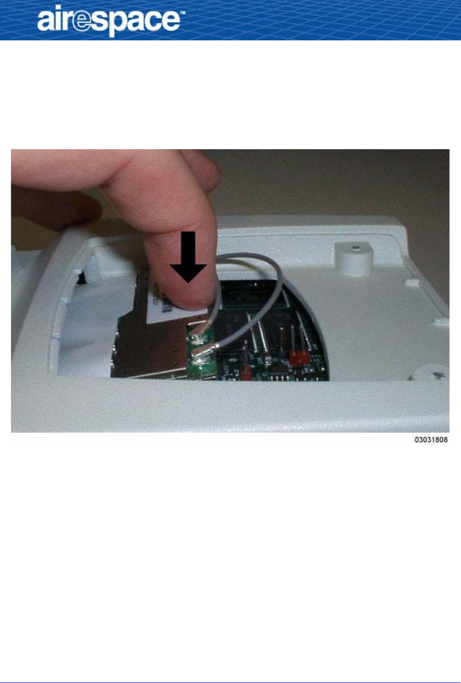
•When you are done, make sure the RF cables are not pinched, and
gently snap the 802.11a Radio Card into its retaining detents as shown
in the next figure.
Figure - Gently Snapping the 802.11a Radio Card into its Retaining Detents

3/18/03 Step 4: Installing the 802.11a Radio Card 11
•When you are done, the 802.11a Radio Card is secured in its retaining
detents as shown in the following figure.
Figure - 802.11a Radio Card Installed in the Airespace AP Case
You have installed the 802.11a Radio Card in the Airspace AP. Continue with
Step 5: Verifying 802.11a Operation.
3/18/03 Step 5: Verifying 802.11a Operation 12
Step 5: Verifying 802.11a Operation
Step 5: Verifying 802.11a Operation
You have added 802.11a functionality to a 1200B Airespace AP. Perform the
following to verify correct 802.11a operation.
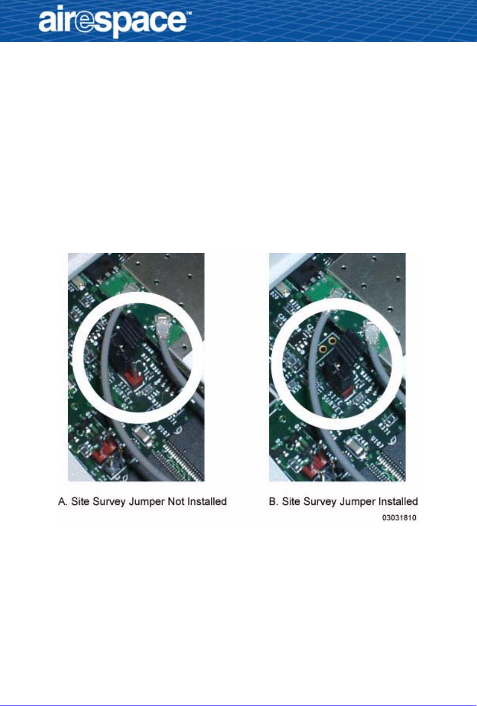
•Enable the Site Survey function by placing the factory-supplied jumper
across both of the Site Survey header pins on the Airespace AP mother-
board as shown in the following figure.
Figure - 802.11a Site Survey Jumper in the Airespace AP
•Put the door back on the Airespace AP case, and use one of the door
screws to temporarily hold the door closed while you apply power to the
Airespace AP.
•Use either an Airespace AP External Power Converter, or a connection
from an 802.3af-compliant Power Over Ethernet device to power up the
Airespace AP.
The red Fault LED should light for about one minute, and then the AP
should begin an up-and-down LED flashing sequence, indicating that
the Airespace AP is receiving power, is not talking to an Airespace

3/18/03 Step 5: Verifying 802.11a Operation 13
Wireless Switch, and that its radios are transmitting their beacon
SSIDs.
•Using your 802.11a WiFi-approved device, verify that you can detect
the SSID “Airespace” and the MAC address from the label in the
802.11a Radio Card kit.
-If you detect the correct SSID and Mac address, the 802.11a
Radio Card is working properly; continue with the next proce-
dure.
-If you cannot detect the correct SSID and Mac address, the
802.11a card is not working properly; contact Airspace Technical
Support at 1-408-635-2000 for assistance.
•When you have verified that the 802.11a Radio Card is working
properly, remove power from the Airespace AP.
•Open the Airespace AP door.
•Move the Site Survey jumper onto either pin for future use.
You have successfully converted the 1200B into a 1200AB. Continue with
Step 6: Closing the Airespace AP Case.

3/18/03 Step 6: Closing the Airespace AP Case 14
Step 6: Closing the Airespace AP Case
Step 6: Closing the Airespace AP Case
•Place the door on the Airespace AP.
•Using your Security Torx screwdriver and the saved screws, secure the
door to the Airespace AP case.
Note: Do not use any other screws to secure the door to Airespace AP.
If you use other screws, you will violate FCC regulations as described
in FCC Statements for Airespace AP.
Continue with Step 6: Updating the Airespace AP FCC Label.

3/18/03 Step 6: Updating the Airespace AP FCC Label 15
Step 6: Updating the Airespace AP FCC Label
Step 6: Updating the Airespace AP FCC Label
Because you have changed a 1200B Airespace AP into a 1200AB Airespace
AP, the FCC certification number has changed. To comply with the FCC regu-
lations described in FCC Statements for Airespace AP, place the correct FCC
label over the existing FCC label.
You have successfully converted the 1200B into a 1200AB Airespace Access
Point.