Airespace WNAP1200B 2.4 GHz 802.11 Access Point User Manual Airespace AP IG 030317
Airespace 2.4 GHz 802.11 Access Point Airespace AP IG 030317
Contents
- 1. Install Guide
- 2. Users Manual
Users Manual
Copyright © 2003 Airespace, Inc. All Rights Reserved. 1
Airspace Access Point (AP)
Installation Guide
Airespace System 1.0: March 17, 2003
Airespace, Inc.
110 Nortech Parkway
San Jose, CA 95134
1-408-635-2000
www.airespace.com
Copyright © 2003 Airespace, Inc. All Rights Reserved.
2
Legal Information
Disclaimer
Airespace™ and Airespace AP™ are trademarks of Airespace, Inc.
All other trademarks, service marks, and product names used in
this document are the property of their respective owners.
U.S.A. Government Restricted Rights
(tbd)
Applicable Laws
(tbd)

Copyright © 2003 Airespace, Inc. All Rights Reserved. 3
FCC Statements
This equipment has been tested and found to comply with the limits for a
Class A digital device, pursuant to Part 15 of the FCC Rules. These limits
are designed to provide reasonable protection against harmful interference
when the equipment is operated in a commercial environment. This
equipment generates, uses, and can radiate radio frequency energy and, if
not installed and used in accordance with the instruction manual, may
cause harmful interference to radio communications. Operation of this
equipment in a residential area is likely to cause harmful interference in
which case the user will be required to correct the interference at his own
expense.
RF Radiation Hazard Warning
To ensure compliance with FCC RF exposure requirements, this
device must be installed in a location such that the antenna of the
device will be greater than 20 cm (8 in.) from all persons. Using
higher gain antennas and types of antennas not covered under the
FCC certification of this product is not allowed.
Note: No 802.11a external antennas are currently certified
or available in this release. Contact Airespace, Inc. for a list of
FCC-approved 802.11b external antennas.
Installers of the radio and end users of the system must adhere to
the installation instructions provided in this manual.
Non-Modification Statement
Use only the supplied internal antenna, or external antennas
supplied by the manufacturer. Unauthorized antennas,
modifications, or attachments could damage the badge and could
violate FCC regulations and void the user’s authority to operate the
equipment.
Copyright © 2003 Airspace, Inc. All Rights Reserved.
4
Table of Contents
Airspace Access Point (AP) Installation Guide 1
Legal Information 2
Disclaimer 2
Trademarks and Service Marks 2
U.S.A. Government Restricted Rights 2
Applicable Laws 2
FCC Statements 3
RF Radiation Hazard Warning 3
Non-Modification Statement 3
Table of Contents 4
About this Guide 5
About the Airespace Access Point 6
About Airespace AP Models and Upgrade Card 9
About the Airespace AP 802.11a Radio Card 10
About Internal and External Airespace AP Antennas 11
About Airespace AP LEDs 12
About Airespace AP Connectors 13
About Airespace AP Physical Security 14
About Power Over Ethernet 15
Installing Airespace APs 16
Planning Airespace AP Locations 17
Mounting Airespace APs 18
Copyright © 2003 Airespace, Inc. All Rights Reserved. 5
About this Guide
The Airespace Access Point (AP) Installation Guide allows installation planners,
network administrators, and installers to work together to install Airespace APs in
a target environment. Refer to the following sections for more information about
the Airespace AP.
Copyright © 2003 Airespace, Inc. All Rights Reserved.
6
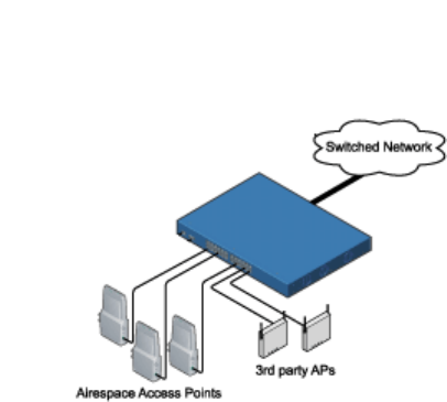
About the Airespace Access Point
The Airespace AP is a part of the innovative Airespace System. When
associated with an Airespace 4000 Switch as shown in the following
figure, the Airespace AP provides advanced 802.11a and/or 802.11b AP
functions in a single sleek enclosure, including unmatched scalability and
security solutions for enterprises and Wireless ISPs. In the Airespace
System, most of the processing power is removed from a traditional AP to
the Airespace Switch.
Airespace Switch and APs

Copyright © 2003 Airspace, Inc. All Rights Reserved. 7
The following figure shows an Airespace AP with the optional ceiling
mount base.
Airespace AP with Ceiling Mount Base
Refer to the following for more information on Airespace APs:
• Airespace AP Models
• Airespace AP 802.11a Radio Cards
• Internal and External Airespace AP Antennas
• About Ethernet Cabling
• Airespace AP LEDs
• Airespace AP Connectors
• Airespace AP Power Requirements
• Airespace AP External Power Converter
• About Power Over Ethernet (PoE)
• Airespace AP Physical Security
• Airespace AP Automatic Software Upgrades
• Airespace AP Specifications
• Installing Airespace APs
Copyright © 2003 Airspace, Inc. All Rights Reserved.
8

Copyright © 2003 Airespace, Inc. All Rights Reserved. 9
About Airespace AP Models and Upgrade
Card
The Airespace AP includes one 802.11a radio (1200A), one
802.11b radio (1200B), or one 802.11a and one 802.11b radio
(1200AB). As an added feature, the 1200B Airespace AP can be
updated by the customer with an 802.11a radio, allowing for
current 802.11b coverage and future 802.11a coverage by the same
Airespace AP. Refer to the Airespace AP 802.11a Radio Card
section for information on the field-installable radio that adds
802.11a capability to an existing 802.11b Airespace AP.
The Airespace AP comes in the following configurations:
• Model 1200A - Airespace AP with one 802.11a radio and
two high-gain internal antennas
• Model 1200B - Airespace AP with one 802.11b radio and
four high-gain internal antennas; can be upgraded to a 1200AB by
adding an 802.11a Radio Card
• Model 1200AB - Airespace AP with one 802.11a and one
802.11b radio and four high-gain internal antennas
The following upgrade card is also available:
• 802.11a Radio Card -Professionalinstallers can add this
card to a 1200B to create a 1200AB Airespace AP
The Airespace AP is shipped with a color-coordinated ceiling
mount base, and projection and flush wall mount brackets. These
brackets and base allow quick mounting to ceiling, wall or pole:
• Ceiling Mounting Kit - Allows you to mount the Airespace
AP on any horizontal surface
• Flush Wall Mount Kit - Allows you to mount the Airespace
AP on a wall with one internal antenna disabled; handy for
installations requiring a directional transmission pattern or an
external antenna.
Note: No 802.11a external antennas are currently certified
or available in this release. Contact Airespace, Inc. for a list of
FCC-approved 802.11b external antennas.
• Projection Wall Mount Kit - Allows you to mount the
Airespace AP on a wall with both (or all four) internal antennas
enabled; handy for installations requiring an omnidirectional
transmission pattern

Copyright © 2003 Airespace, Inc. All Rights Reserved.
10
About the Airespace AP 802.11a Radio Card
The 1200B (802.11b) Airespace AP can be upgraded to a 1200AB
(802.11a and 802.11b) Airespace AP by adding a professionally-
installed 802.11a radio card.
The 802.11a radio supports diversity between the internal antennas
and a factory-supplied external antenna.
Refer to the Airespace AP 802.11a Radio Card Quick Install Guide
for professional installer instructions.
Note: No 802.11a external antennas are currently certified
or available in this release. Contact Airespace, Inc. for a list of
FCC-approved 802.11b external antennas.
Note: The Airespace APs must use the factory-supplied
internal or external antennas to avoid violating FCC regulations
and voiding the user’s authority to operate the equipment.

Copyright © 2003 Airespace, Inc. All Rights Reserved. 11
About Internal and External Airespace AP
Antennas
The 1200A Airespace AP enclosure contains one 802.11a radio
which drives two fully-enclosed high-gain antennas which provide
a large 360-degree coverage area. When equipped with a factory-
supplied external antenna, the 802.11a radio supports receive and
transmit diversity between the internal antennas and the external
antenna.
Note: No 802.11a external antennas are currently certified
or available in this release. Contact Airespace, Inc. for a list of
FCC-approved 802.11b external antennas.
The diversity function provided by Airespace radios can result in
lower multipath fading, fewer packet retransmits, and higher
throughput to and from clients.
Note: The Airespace APs must use the factory-supplied
internal or external antennas to avoid violating FCC regulations
and voiding the user’s authority to operate the equipment.
The 1200AB Airespace AP enclosure contains one 802.11a and
one 802.11b radio and four fully-enclosed high-gain antennas
which provide large 360-degree 802.11a and 802.11b coverage
areas. Note that the 802.11b radio supports receive and transmit
diversity between the internal antennas, while the 802.11a radio
supports diversity between the internal antennas and a factory-
supplied external antenna.
The 1200B Airespace AP enclosure contains one 802.11b radio
and a slot for an 802.11a radio card, and four high-gain antennas,
which provide large 360-degree 802.11b (and future 802.11a)
coverage areas. The 802.11b radio supports receive and transmit
diversity between the internal antennas. Note that the 802.11a
radio supports diversity between the internal antennas and a
factory-supplied external antenna.
Note: No 802.11a external antennas are currently certified
or available in this release. Contact Airespace, Inc. for a list of
FCC-approved 802.11b external antennas.
The Airespace APs have reverse-polarity TNC jacks for
installations requiring factory-supplied external directional or high-
gain antennas. The Airespace AP has one 802.11a external antenna
jack and two 802.11b external antenna jacks, which allow the
Airespace AP radios to provide transmit and receive diversity
using external antennas. This option can create more flexibility in
Airespace AP and antenna placement.

Copyright © 2003 Airspace, Inc. All Rights Reserved.
12
Note: No 802.11a external antennas are currently certified
or available in this release. Contact Airespace, Inc. for a list of
FCC-approved 802.11b external antennas.
Copyright © 2003 Airespace, Inc. All Rights Reserved. 13
About Airespace AP LEDs
Each Airespace AP is equipped with four LEDs across the top of
the case. They can be viewed from nearly any angle. The LEDs
indicate power and fault status, radio slot 1 link activity, and radio
slot 2 link activity.
This LED display thus gives a quick overview of the Airespace AP
status. For more detailed troubleshooting instructions, refer to the
Troubleshooting the Airespace AP section (to be determined).

Copyright © 2003 Airespace, Inc. All Rights Reserved.
14
About Airespace AP Connectors
The Airespace AP has the following external connectors:
• One RJ-45 jack, used for connecting the Airespace AP to
the Airespace Switch.
• One 48 VDC power input jack, used to plug an optional
factory-supplied external power adapter into the Airespace AP.
• Three reverse-polarity TNC antenna jacks, used to plug
optional external antennas into the Airespace AP--two for an
802.11b radio, and one for an 802.11a radio.
Note: No 802.11a external antennas are currently certified
or available in this release. Contact Airespace, Inc. for a list of
FCC-approved 802.11b external antennas.
The Airespace AP communicates with an Airespace Switch using
standard CAT5 (Category 5) or higher 10/100 Mbps unshielded
twisted pair cable with RJ-45 connectors. Plug the CAT5 cable
into the RJ-45 jack on the side of the Airespace AP.
Note that the Airespace AP can receive power over the CAT5
cable from the Airespace Switch or other equipment. Refer to
About Power Over Ethernet for more information about this
option.
The Airespace AP can be powered from an optional factory-
supplied external AC-to-48 VDC power adapter. If you are
powering the Airespace AP using an external adapter, plug the
adapter into the 48 VDC power jack on the side of the Airespace
AP.
The Airespace AP includes two 802.11a and two 802.11b high-
gain internal antennas, which provide omnidirectional coverage.
However, the Airespace AP can also use optional factory-supplied
external high-gain and/or directional antennas; one for an 802.11a
radio and two for an 802.11b radio. When used with external
antennas, each Airespace AP radio supports diversity, if enabled.
When you are using external antennas, plug them into the reverse-
polarity TNC jacks on the side of the Airespace AP.
Note: No 802.11a external antennas are currently certified
or available in this release. Contact Airespace, Inc. for a list of
FCC-approved 802.11b external antennas.
Note: The Airespace APs must use the factory-supplied
internal or external antennas to avoid violating FCC regulations
and voiding the user’s authority to operate the equipment.
Copyright © 2003 Airespace, Inc. All Rights Reserved. 15
About Airespace AP Physical Security
The side of the Airespace AP housing includes a slot for a
Kensington MicroSaver Security Cable. You can use any
MicroSaver Security Cable to ensure that your Airespace AP stays
where you mounted it!
Copyright © 2003 Airespace, Inc. All Rights Reserved.
16
About Power Over Ethernet
Airespace equipment supports 802.3af-compliant Power over Ethernet
(PoE), which can reduce the cost of discrete power supplies, additional
wiring, conduits, outlets, and installer time. PoE also frees installers from
having to mount the Airespace APs near AC outlets, which allows more
flexibility in positioning Airespace APs for maximum coverage. Finally,
systems with fewer wires generally have lower failure rates.
When you are using PoE, the installer runs a single CAT5 cable from each
Airespace AP to the PoE-equipped Airespace Switch or other network
element, or to a PoE power hub. When the PoE equipment determines that
the Airespace AP is a powered device, it sends 48 VDC over unused pairs
in the Ethernet cable to the Airespace AP.
Airespace APs can receive power from the Airespace Switch, or any other
network device conforming to the IEEE 802.3af standard.
When a Airespace Switch is operated in Appliance Mode, it can be
ordered without PoE, as the switching element it is connected through can
be equipped with internal PoE or an external PoE hub. When a Airespace
Switch is operated in Direct Connect Mode, it can be ordered with internal
PoE or an external PoE hub. Contact Airespace for recommended external
PoE hubs.

Copyright © 2003 Airespace, Inc. All Rights Reserved. 17
Installing Airespace APs
Installing Airespace APs is a two-part process. First, you must plan where
the Airespace APs are to be located to provide the desired coverage, and
then you install the Airespace APs in the desired locations. Continue with
the following:
• Planning Airespace AP Locations
• Mounting Airespace APs

Copyright © 2003 Airespace, Inc. All Rights Reserved.
18
Planning Airespace AP Locations
This planning section provides information necessary for the
installer to quickly and easily plan, install, and test Airespace AP
Radio Frequency coverage in an end-user environment.
Before you start the Airespace AP Planning process, please read
the Planning Notes. Once you have read the Planning Notes,
continue with the following steps:
1 Collecting Tools and Materials
2 Preparing Optional Trial Assemblies
3 Surveying the Site
4 Determining Airespace AP Coverage and Locations
5 Positioning Airespace APs
6 Verifying Airespace AP Coverage
7 Where to Go From Here

Copyright © 2003 Airespace, Inc. All Rights Reserved. 19
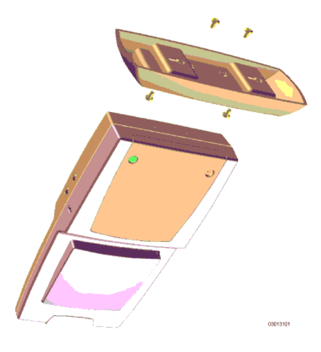
Mounting Airespace APs
After completing the steps in the Planning Airespace AP
Locations section, mount Airespace APs as follows. Refer to the
following figure for installation details.
Note: When mounting Airespace APs, make sure to
maintain a 20 cm (8 in.) separation between the Airespace APs and
any persons to comply with FCC RF exposure regulations. Refer to
the FCC Statements section for more FCC information.
1 Collect the following supplies:
! Screwdrivers, drills, and ladder.
! An assortment of sheet metal and drywall screws and
toggle bolts.
! Airespace AP Vertical Mount Kits, one per Airespace AP
as required.
! Airespace AP Wall Mount Kits, one per Airespace AP as
required.
! CAT5 cables between the Airespace AP locations and the
planned Airespace Switch location.
2 Using the mounting kits supplied with each Airespace AP,
mount the Airespace AP in its final location. The following figure
shows the an Airespace AP and the ceiling mount. (Mounting
details to be determined.)
3 Mark the final mounting locations on the maps or
floorplans, including the "Front" direction, if the Airespace AP is
to be used with diversity disabled.
4 Copy the MAC Address(es) from the bottom of each
Airespace AP onto the maps or floorplans.
5 If the CAT5 cabling that will connect the Airespace APs to
the Airespace Switch is available, plug it into the Airespace AP
now.
Airespace AP and Ceiling Mount Assembly
Copyright © 2003 Airspace, Inc. All Rights Reserved.
20