Airspan Networks AIRSPAN-BSR900 Base Station Radio (BSR) User Manual Part 2A
Airspan Networks Inc Base Station Radio (BSR) Users Manual Part 2A
Contents
- 1. Users Manual Part 1
- 2. Users Manual Part 2A
- 3. Users Manual Part 2B
- 4. Users Manual Part 3
Users Manual Part 2A
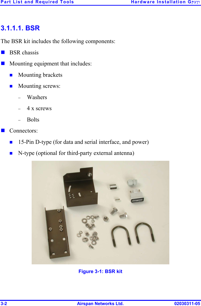
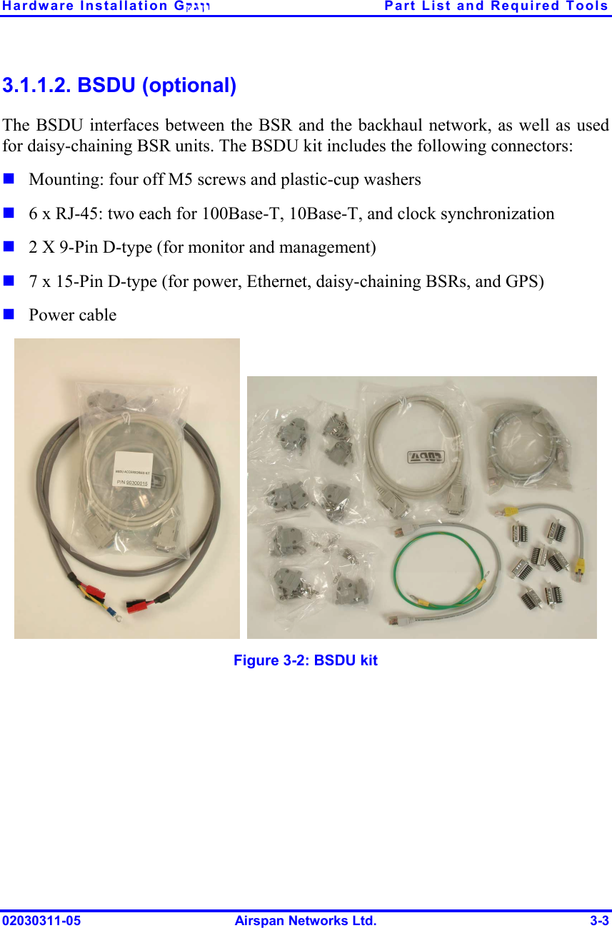
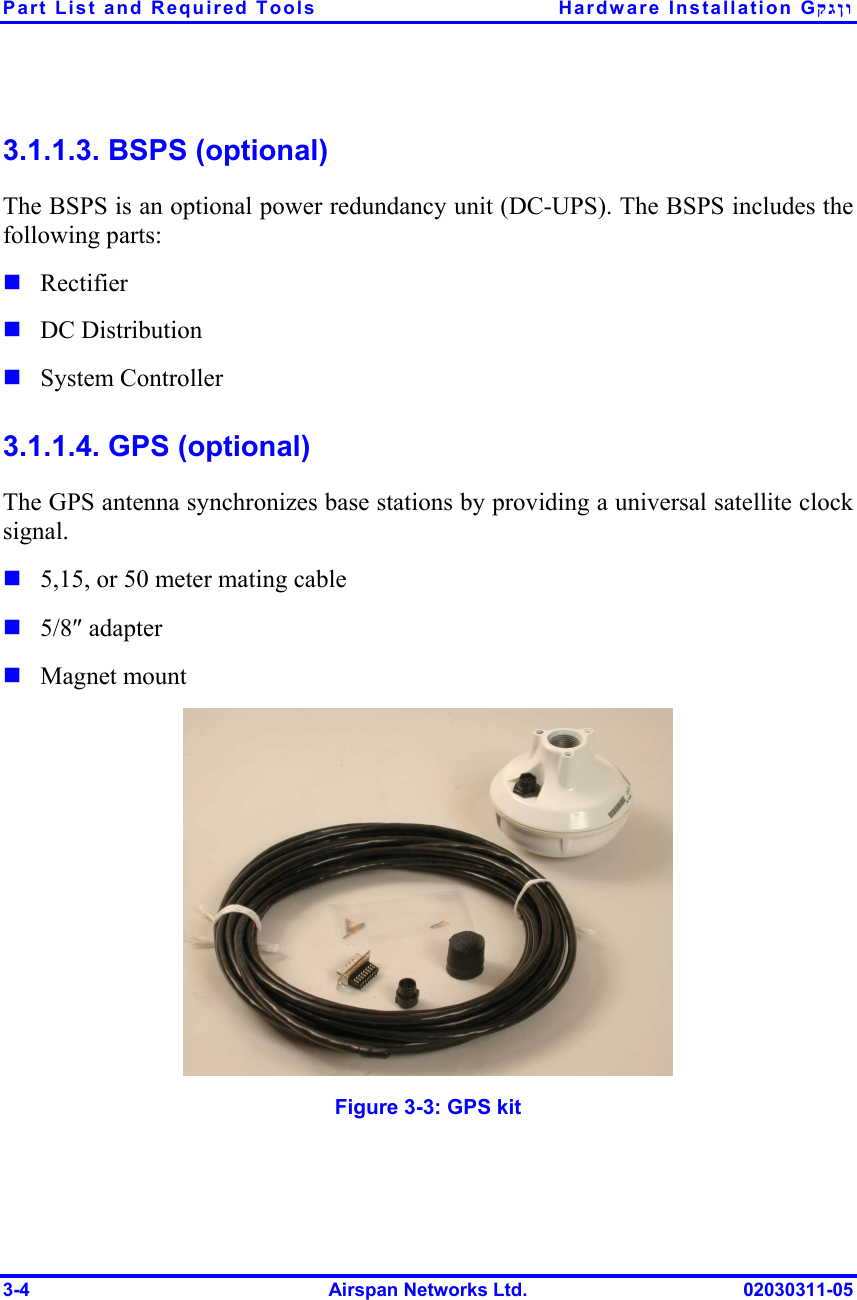
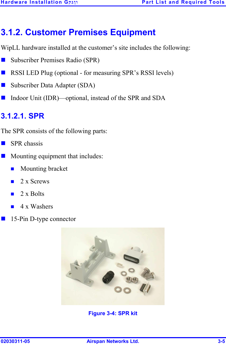
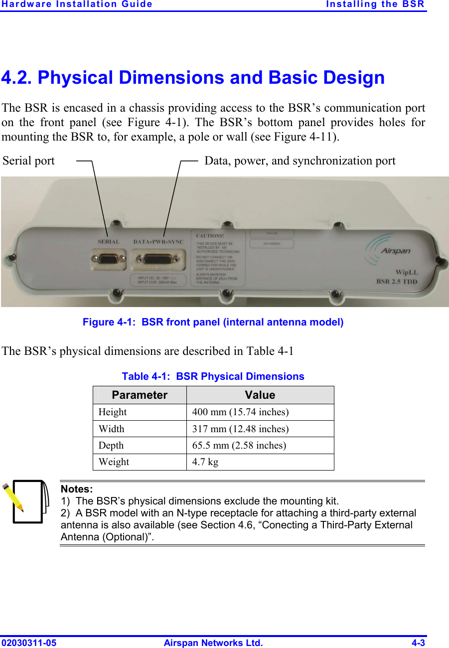
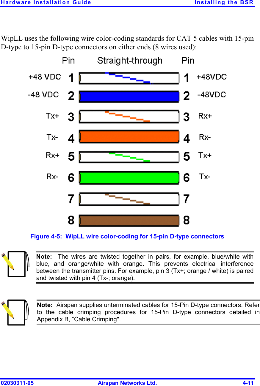
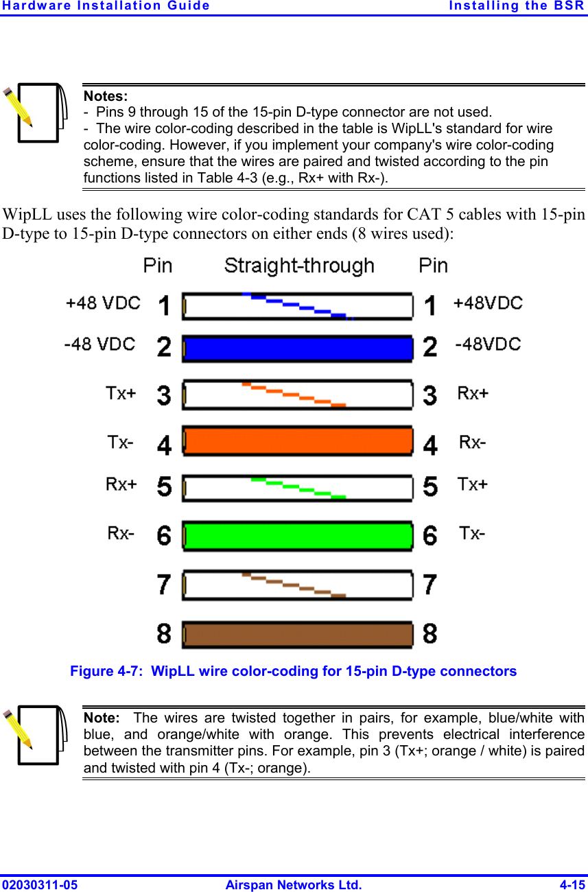
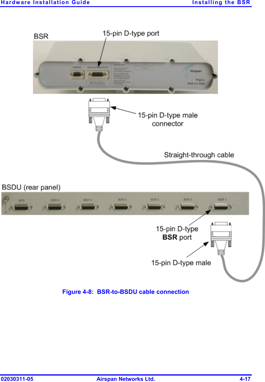
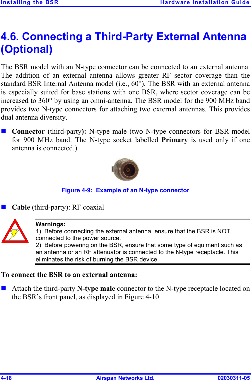
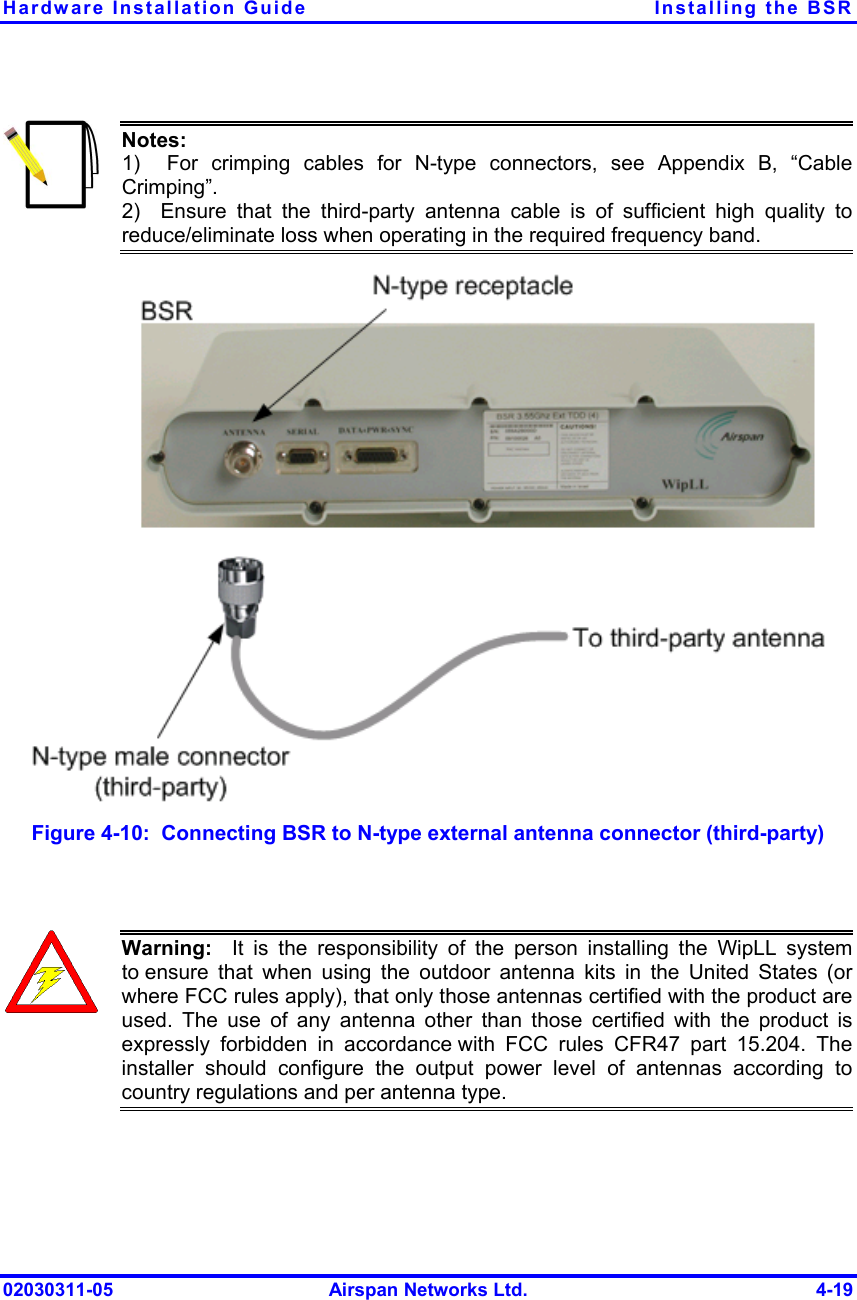
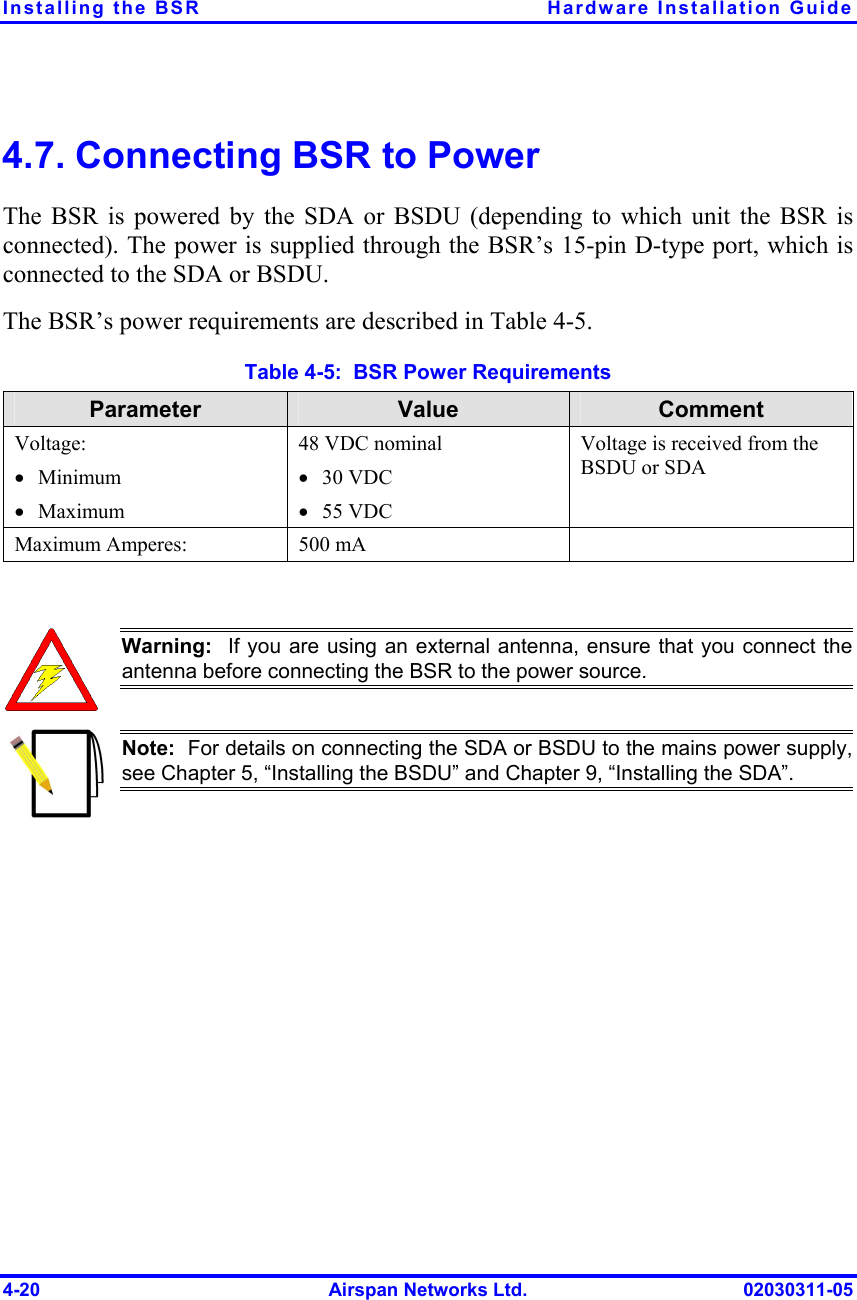
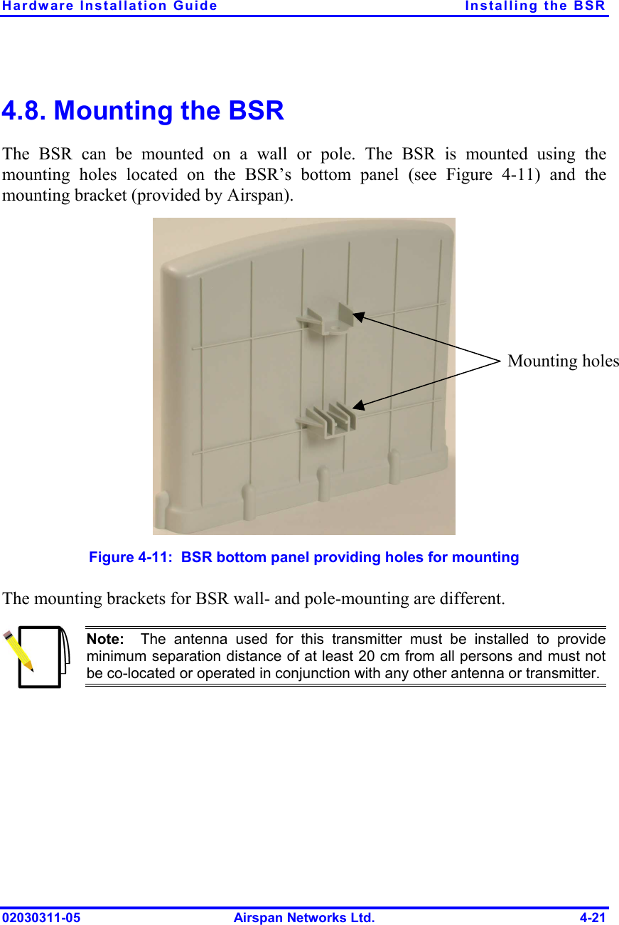
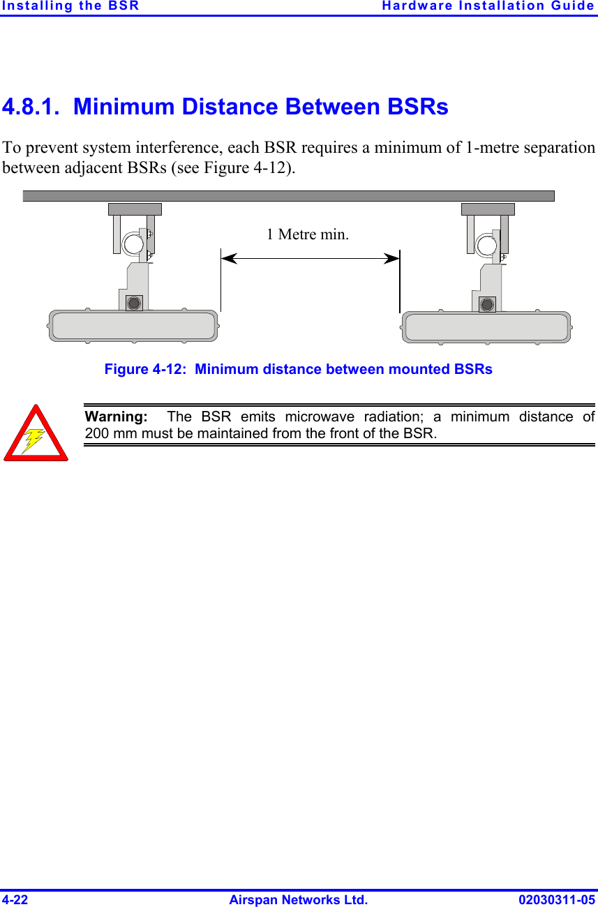
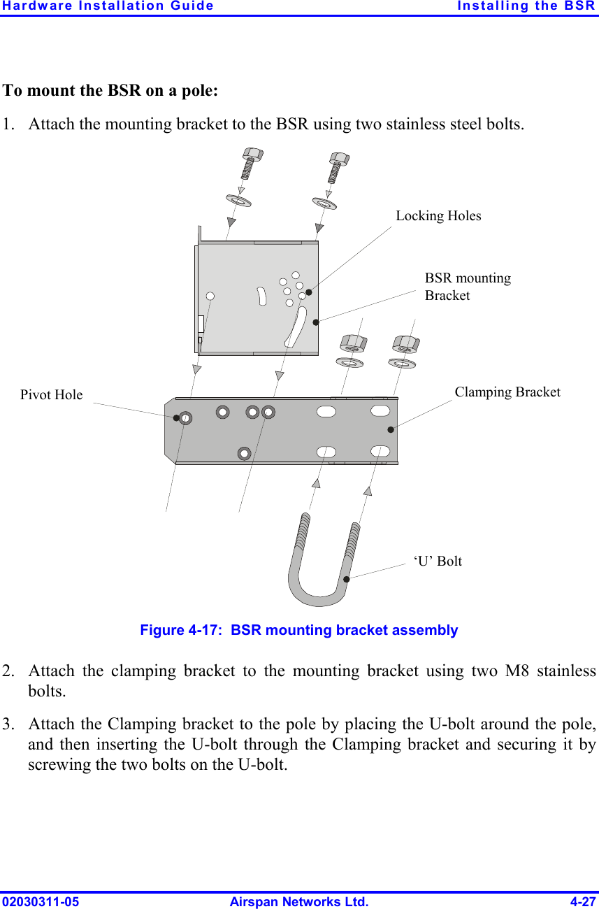
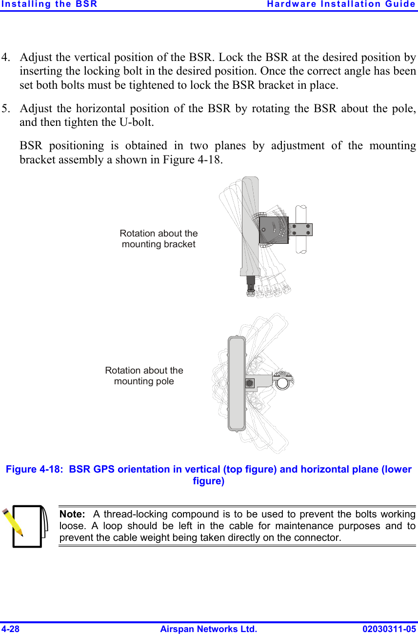
![Installing the BSR Hardware Installation Guide 4-2 Airspan Networks Ltd. 02030311-05 4.1. Overview The BSR is the center of the WipLL system. The BSR provides last-mile wireless connectivity by connecting the provider’s backhaul network to the subscriber’s wireless unit (Subscriber Premises Radio [SPR]). In addition, the BSR is responsible for synchronizing the WipLL network (i.e., synchronizing SPRs/IDRs). For base stations consisting of a single BSR, the BSR is typically powered and connected to the provider’s backhaul network by the WipLL Subscriber Data Adapter (SDA). For base stations consisting of multiple BSRs, the BSRs are powered and connected to the provider’s backhaul by the WipLL Base Station Distribution Unit (BSDU). The BSR is available in three models: ! BSR with a built-in antenna ! BSR with an N-type port for connection to an optional third-party external antenna ! BSR with an two N-type ports for connection to two optional third-party external antennas for dual antenna diversity](https://usermanual.wiki/Airspan-Networks/AIRSPAN-BSR900.Users-Manual-Part-2A/User-Guide-388061-Page-14.png)