Airspan Networks AIRSPAN-BSR900 Base Station Radio (BSR) User Manual Part 3
Airspan Networks Inc Base Station Radio (BSR) Users Manual Part 3
Contents
- 1. Users Manual Part 1
- 2. Users Manual Part 2A
- 3. Users Manual Part 2B
- 4. Users Manual Part 3
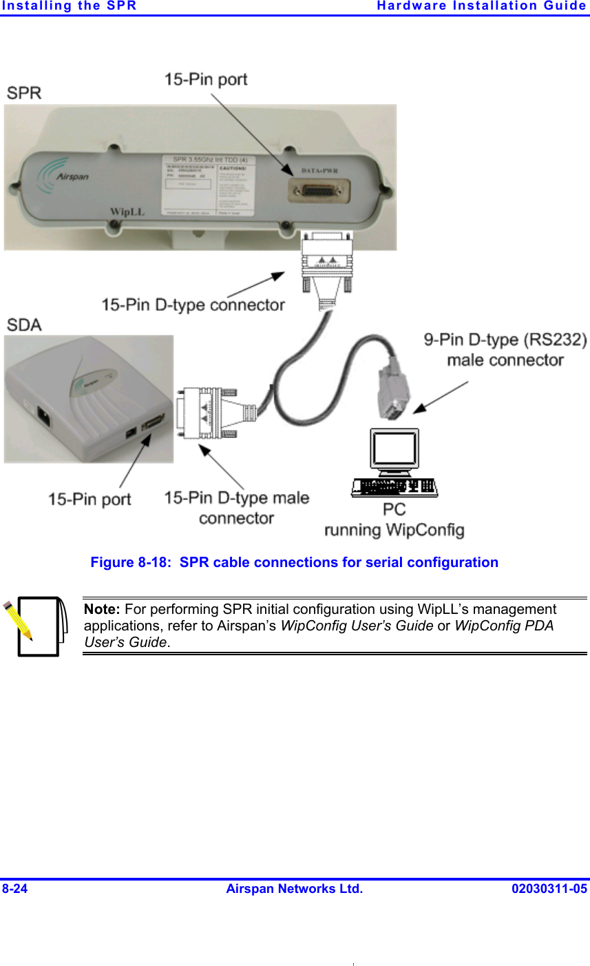
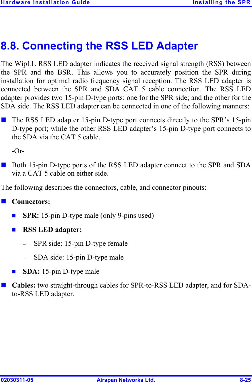
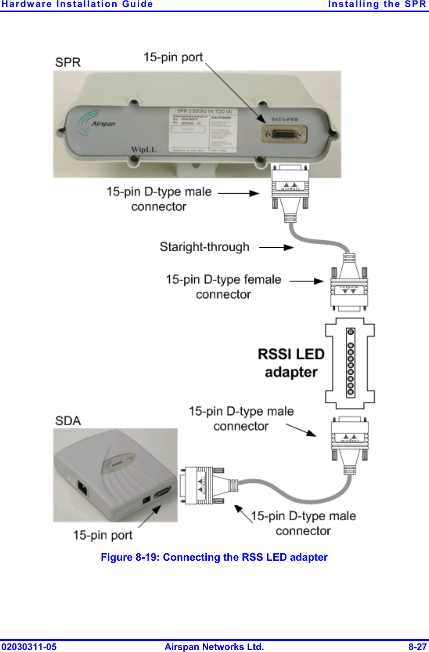
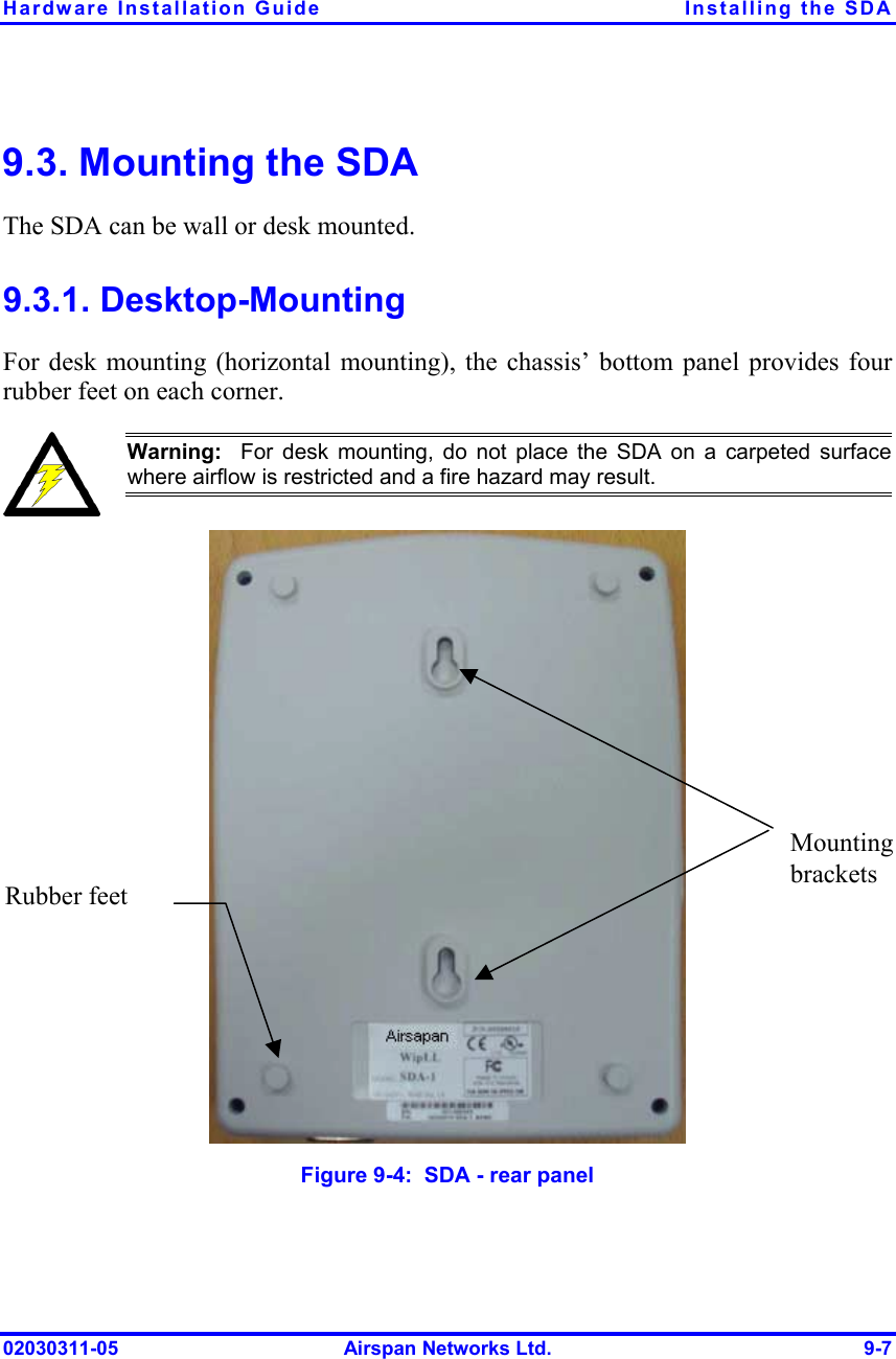
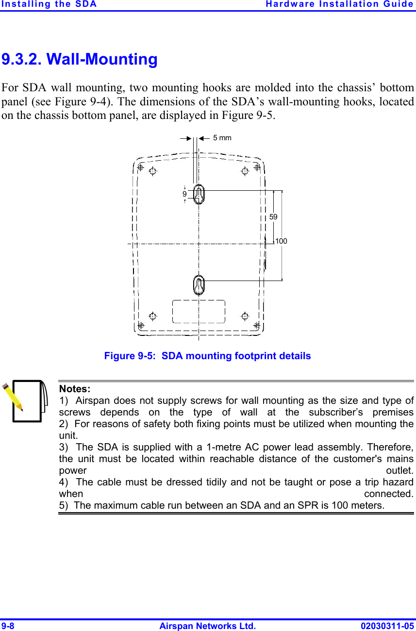
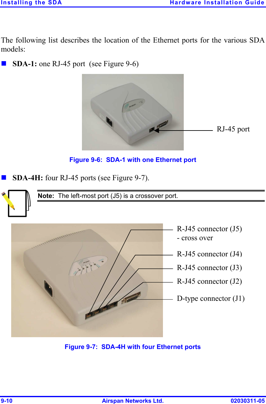
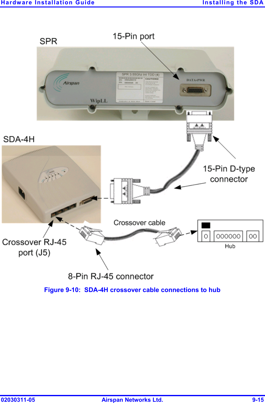
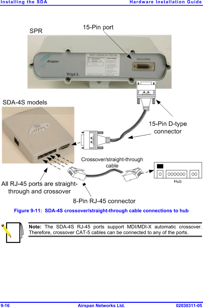
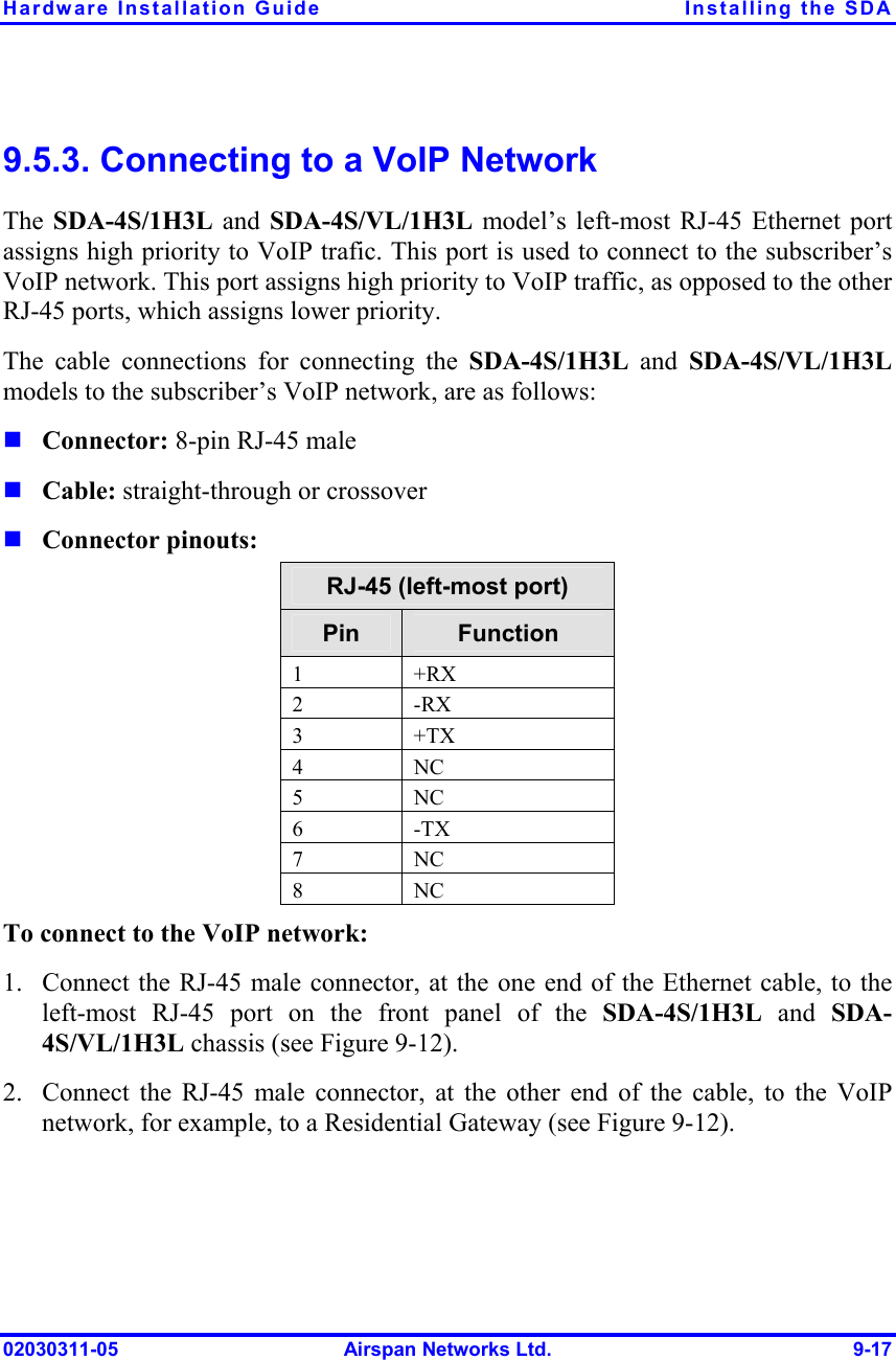
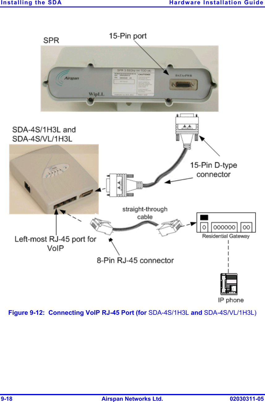
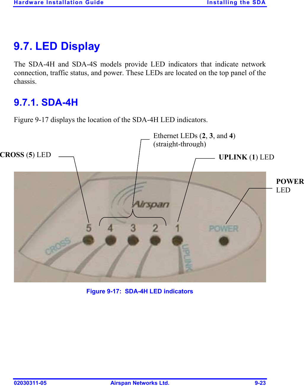
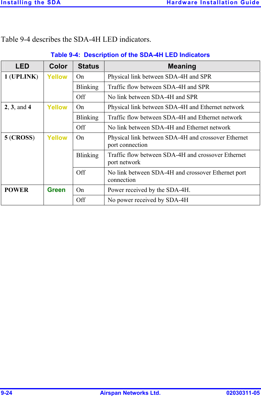
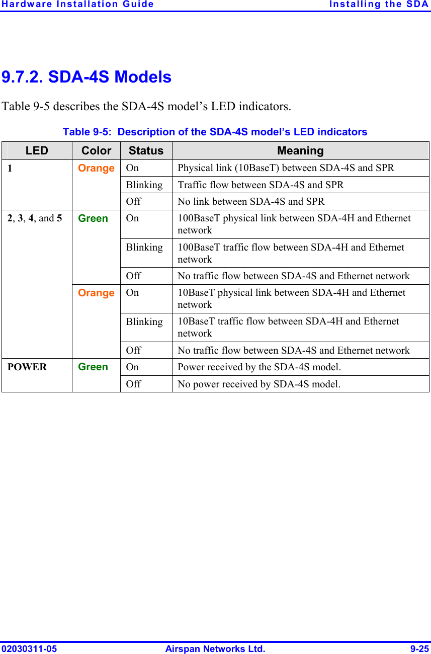
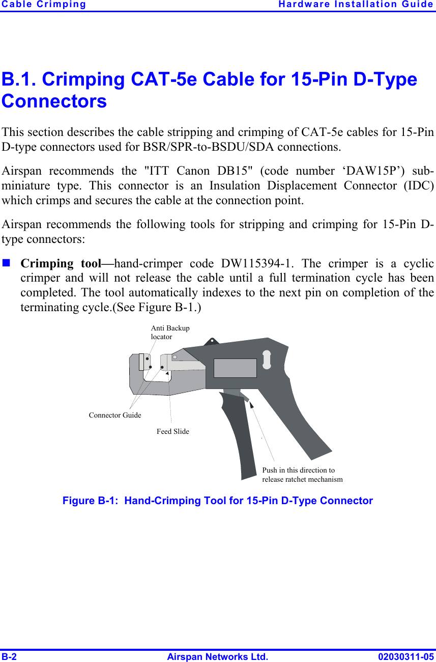
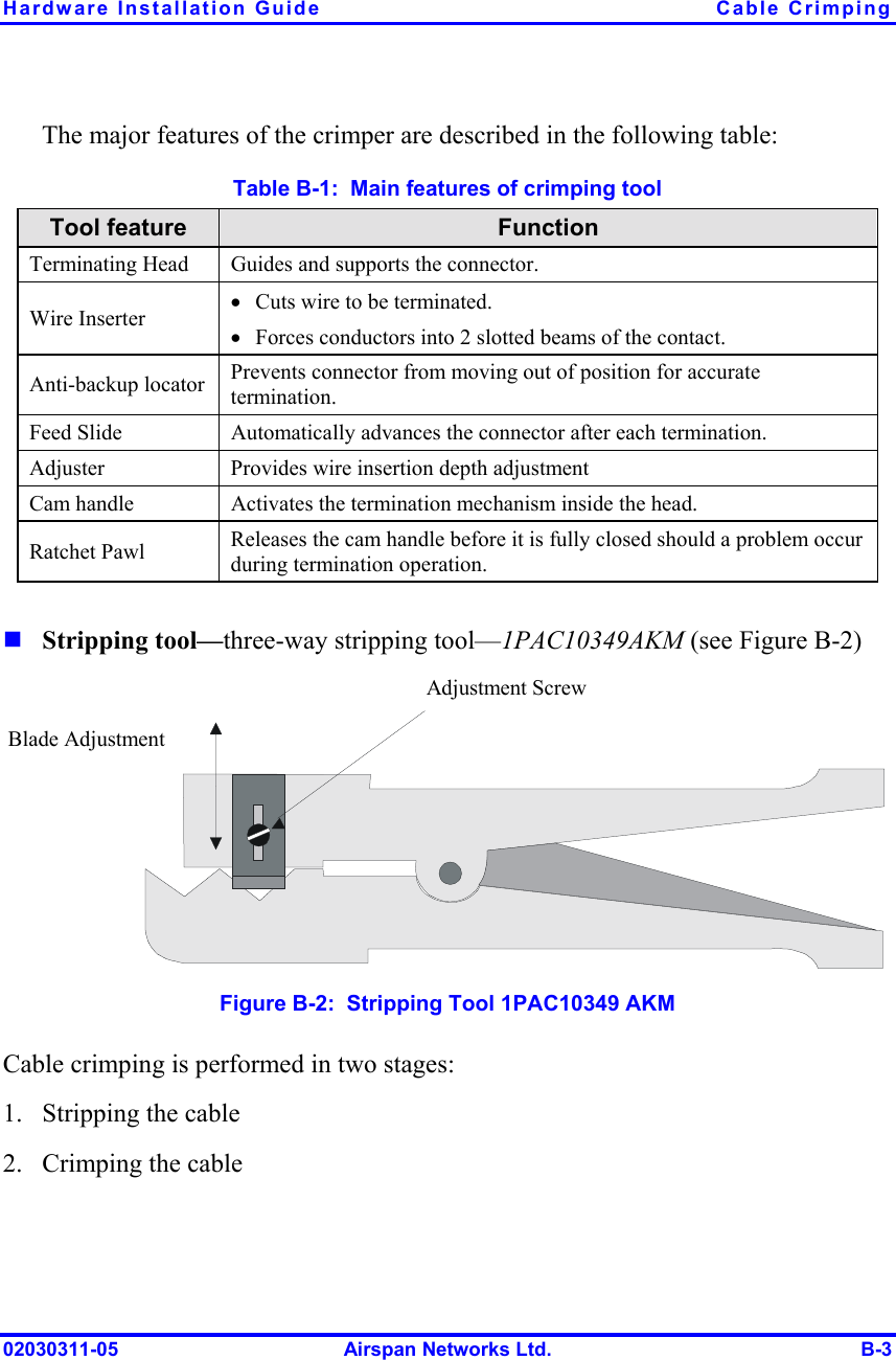
Users Manual Part 3