Airspan Networks AIRSPAN-BSR900 Base Station Radio (BSR) User Manual Part 3
Airspan Networks Inc Base Station Radio (BSR) Users Manual Part 3
Contents
- 1. Users Manual Part 1
- 2. Users Manual Part 2A
- 3. Users Manual Part 2B
- 4. Users Manual Part 3
Users Manual Part 3

Installing the BSPS Hardware Installation Guide
7-28 Airspan Networks Ltd. 02030311-05
Symptom Possible Cause Remedy
between any two
modules).
• Rectifier(s) are not properly
adjusted.
• Re-adjust the voltage of the
problematic rectifier(s).
Battery backup time
is too low
• Battery is too small for the
application.
• Charging voltage is too low
• Weak battery
• Increase battery capacity
• Raise the system output voltage
using the “VOLT ADJ.”
• Replace the battery and check
ambient temperature according to
manufacturer’s instructions

Part II
Part IIPart II
Part II
Installing WipLL Customer
Installing WipLL Customer Installing WipLL Customer
Installing WipLL Customer
Premises Equipment
Premises EquipmentPremises Equipment
Premises Equipment
Part II describes the procedures for installing the WipLL equipment located at the
subscriber’s premises.
Part II includes the following chapters:
! Chapter 8, “Installing the SPR”
! Chapter 9, “Installing the SDA”
! Chapter 10, “Installing the IDR”
This page is intentionally left blank.

02030311-05 Airspan Networks Ltd. 8-1
Installing the SPR
Installing the SPRInstalling the SPR
Installing the SPR
This chapter describes the installation of the WipLL Subscriber Premises Radio
(SPR) at the subscriber's premises.
This chapter includes the following chapters:
! Overview
! Physical Dimensions and Basic Design
! Cable Guidelines
! Mounting the SPR
! Minimum Distance between SPRs
! Wall Mounting
! Pole Mounting
! Connecting an External Third-Party Antenna (Optional)
! Connecting to the SDA
! Connecting to a PC for Serial Configuration
! Connecting the RSS LED Adapter
! Connecting Power
8

Installing the SPR Hardware Installation Guide
8-2 Airspan Networks Ltd. 02030311-05
8.1. Overview
The SPR receives and transmits data from and to the base station. The SPR connects
to the subscriber’s network through the SDA. The SDA is an Ethernet hub/LAN
switch (depending on SDA model) that provides the SPR with DC power, lightening
protection, and Ethernet (10Base-T and/or 100Base-T )connectivity to the
subscriber’s PCs/network (up to four PCs depending on SDA model). The SPR
connects to the SDA by a CAT-5 cable.
The SPR is typically mounted on the subscriber's roof or external wall; the SDA is
installed inside the subscriber's premises.
The SPR is available in the following models:
! SPR with Standard Gain: includes a built-in antenna 15-dBi antenna gain,
covering an area of 23 degrees
! SPR with High-Gain Antenna: includes a built-in antenna with an 18-dBi
antenna gain, covering 15 degrees.
! SPR with External Antenna: includes an N-type connector port for attaching a
third-party external antenna.
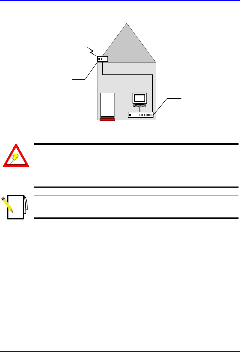
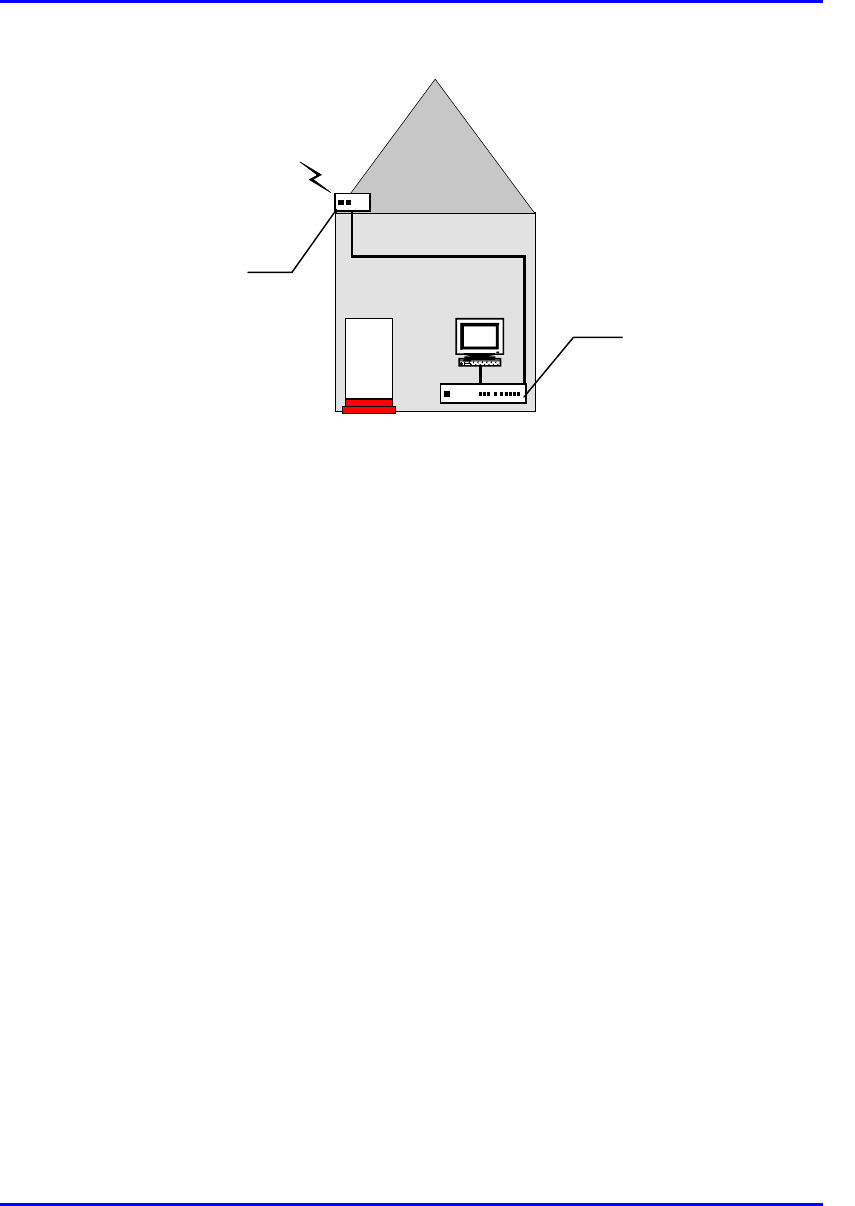
Figure 8-1 displays a typical setup of the SPR and SDA at the subscriber's premises.
Note: The SDA can also be installed at a base station that has only one BSR.
This SDA replaces the need for the BSDU, and provides power and
connectivity to the single BSR.
Hardware Installation Guide Installing the SPR
02030311-05 Airspan Networks Ltd. 8-3
RF link
CAT-5e
PC
Figure 8-1: Typical SPR and SDA location and connections at subscriber's premises
Warning: As the system emits microwave radiation, a minimum distance o
f
200 mm must be maintained from the front of the SPR.
To avoid electrical or fire hazard, connect the SPR to the power supply only
after mounting the SPR and connecting data cables between the SPA and
SDA units.
Note: Usually, the SPR is initialized (i.e., configured with an IP address) at
Airspan's factory. However, if the SPR has not been configured, see Section
8.7, “Connecting to a PC for Serial Configuration”, before mounting the SPR.
Subscriber Data
Adapter (SDA)
located inside
Subscriber Premises
Radio (SPR) located
on the roof

Installing the SPR Hardware Installation Guide
8-4 Airspan Networks Ltd. 02030311-05
Note: The digital portion of the transceiver has been tested and found to
comply with the limits for a Class B digital device, pursuant to part 15 of the
FCC rules. These limits are designed to provide reasonable protection against
harmful interference in a residential installation. This equipment generates,
uses, and can radiate radio frequency energy and, if not installed and used in
accordance with the instructions, may cause harmful interference to radio
communications. However, there is no guarantee that interference will not
occur in a particular installation. If this equipment does cause harmful
interference to radio or television reception, which can be determined by
turning the equipment on and off, the user is encouraged to try correct the
interference by performing one or more of the following measures:
- Reorientate or relocate the receiving antenna
- Increase separation between the equipment and receiver
- Connect the equipment to an outlet on a circuit different from that to which
the receiver is connected
- Consult the dealer or an experienced radio/TV technician for help
Hardware Installation Guide Installing the SPR
02030311-05 Airspan Networks Ltd. 8-5
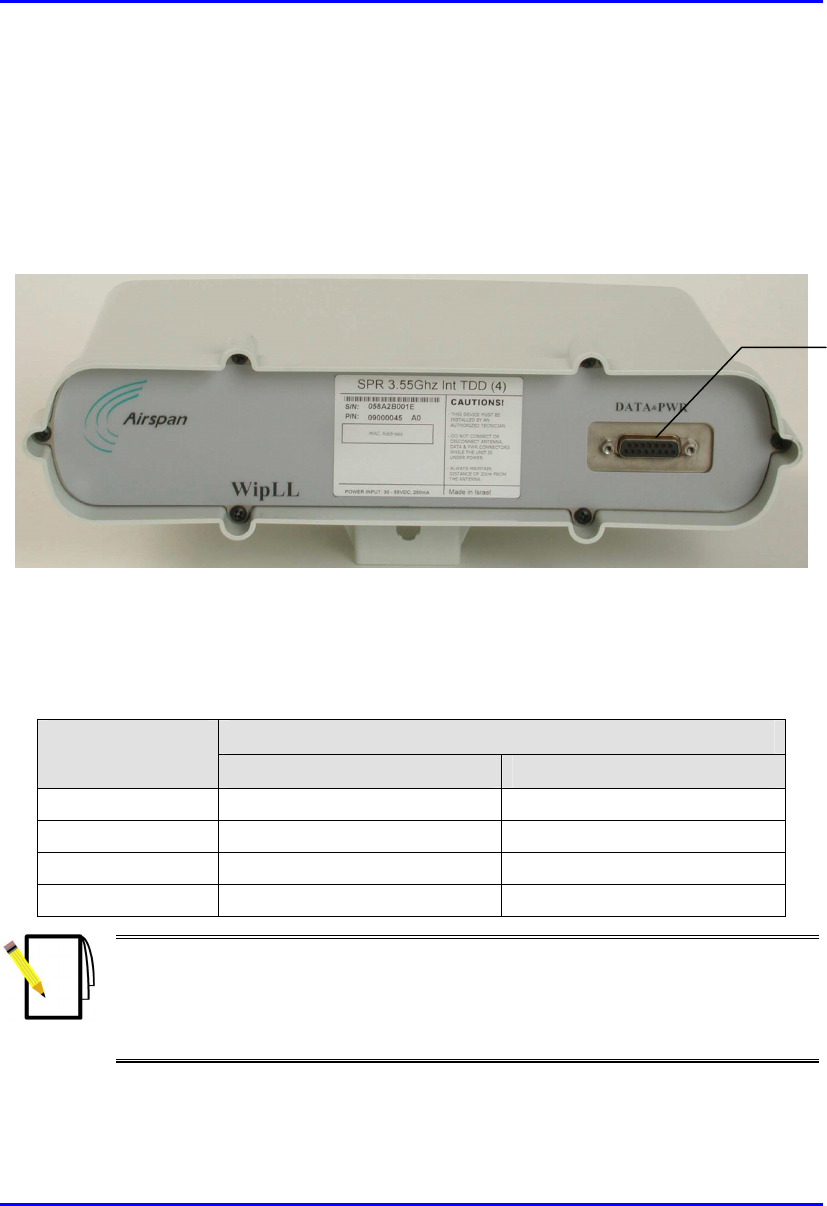
8.2. Physical Dimensions and Basic Design
The SPR is encased in a chassis and provides access to the SPR’s communication
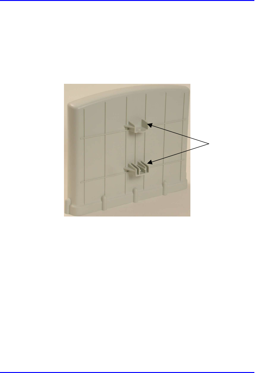
port at the front panel. The SPR’s bottom panel provides holes for mounting the
SPR to, for example, a pole or wall (see Figure 8-3).
Figure 8-2: SPR (with built-in antennal)
The SPR’s physical dimensions are described in Table 8-1
Table 8-1: SPR physical dimensions
SPR model Parameter
Standard Gain Antenna High Gain Antenna
Height 311 mm (12.24 inches) 400 mm (15.74 inches)
Width 224 mm (8.82 inches) 317 mm (12.48 inches)
Depth 65.5 mm (2.58 inches) 65.5 mm (2.58 inches)
Weight 2.5 kg 4.7 kg
Notes:
1) The SPR’s physical dimensions exclude the mounting kit.
2) An SPR model with an N-type receptacle for attaching a third-party external
antenna is also available (see Section 8.5, “Connecting a Third-Party External
Antenna (Optional)”.
15-pin D-type
p
ort

Installing the SPR Hardware Installation Guide
8-6 Airspan Networks Ltd. 02030311-05
8.3. Cable Guidelines
The following lists cable installation guidelines at the subscriber's premises:
! To prevent tripping, a wiring duct is to be provided at the subscriber's premises
to house data cables. Wiring channel type, location, and methods of securing are
to be discussed with the subscriber.
! Cables not housed in wiring channel must be dressed in a manner to avoid a trip
hazard. Avoid trailing wires across passageways.
! External data cables are to be protected in metal conduit that is to be secured to
the building structure in accordance with manufacturers recommendations.
! Outside wiring channels must not be located as to cause a trip hazard (e.g. roof
walkways)
! Observe recommended minimum bend radii when installing copper cables.
Wherever a cable changes direction, ensure that it does so in a smooth curve
with a radius of at least 50 mm in order to prevent damage.
! A maintenance loop is to be left in the cable just before the cable reaches the
SPR to prevent strain on the connector.
! Data cables threaded into holes drilled in walls are to be covered by a waterproof
sheath to prevent water penetration.
! Silicone sealant should be used to plug any holes on both internal and external
wall surfaces once cables are in place.
! All data cables should be labeled with both the source and destination at each
end. Un-used cable ends must also be identified with labels to assist with future
upgrades.
Warning: Cables with exposed ends (i.e., not yet crimped) should be covered
with protective polythene bags during external cable installation processes.
Note: A minimum separation of 200 mm should exist between power and data
cables.
Hardware Installation Guide Installing the SPR
02030311-05 Airspan Networks Ltd. 8-7
8.4. Mounting the SPR
The SPR can be mounted on a wall or pole. The SPR is mounted using the mounting
holes located on the SPR’s bottom panel (see Figure 8-3), and the mounting bracket
(provided). The mounting brackets for wall- and pole-mounting are different from
one another.
Figure 8-3: SPR bottom panel providing holes for mounting
Mounting holes
Installing the SPR Hardware Installation Guide
8-8 Airspan Networks Ltd. 02030311-05
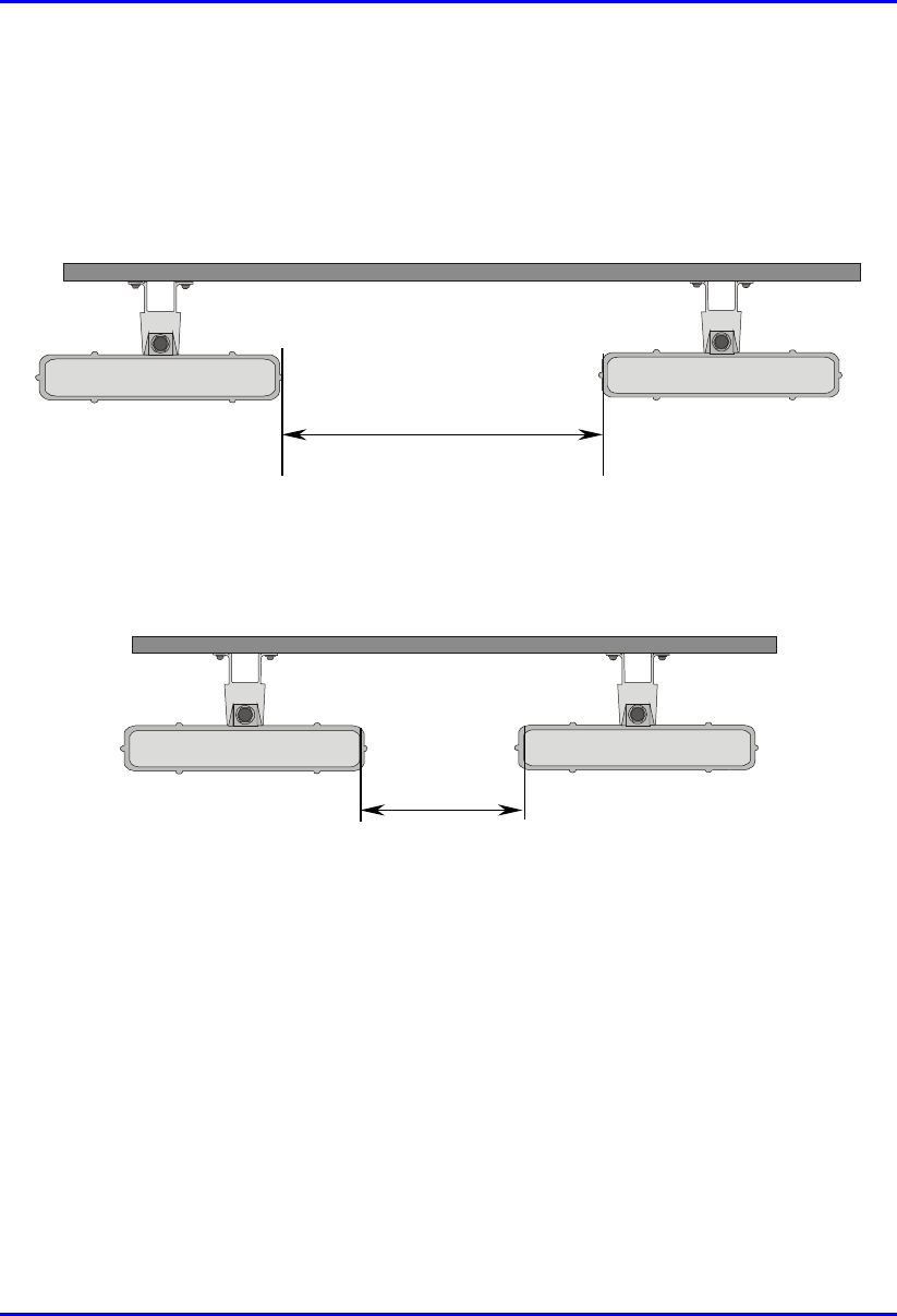
8.4.1. Minimum Distance between SPRs
A minimum of 3-meter separation is required between mounted SPRs and existing
customer radio equipment when not transmitting on the same sector (see Figure 8-4).
3.0 metres
Figure 8-4: SPR separation when not transmitting on the same sector
A 1-meter separation is required between SPRs when on the same sector and
transmitting to the same BSR without requiring shielding (see Figure 8-5).
1.0 metre
Figure 8-5: SPR separation when transmitting on the same sector to the same BSR
Hardware Installation Guide Installing the SPR
02030311-05 Airspan Networks Ltd. 8-9
8.4.2. Wall-Mounting
SPR wall mounting is performed in two chronological stages:
! Attaching the mounting bracket to the SPR’s mounting holes.
! Attaching the mounting bracket (attached to the SPR) to the wall.
To mount the SPR on a wall:
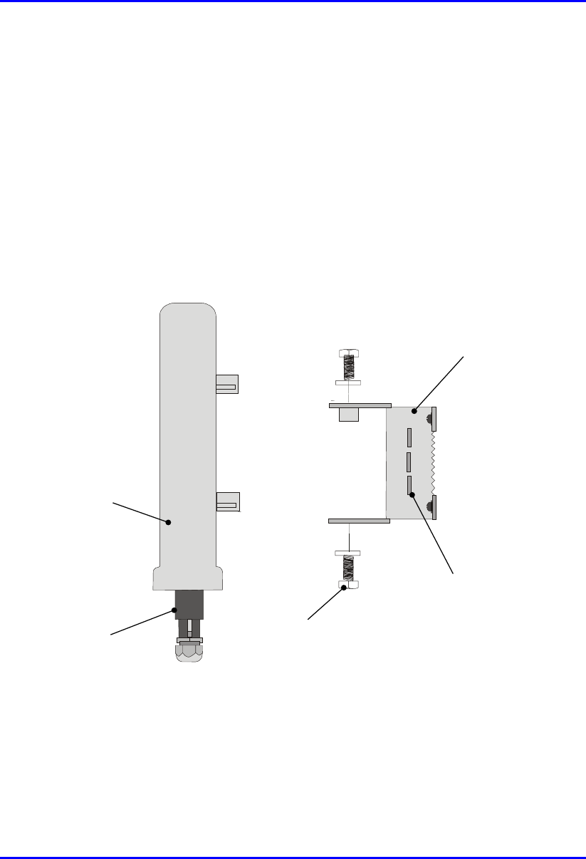
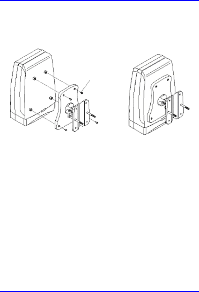
1. Attach the mounting bracket to the SPR using two stainless steel bolts, as shown
in Figure 8-6.
Jubilee clip slots
BSR
BSR Fixing Bolts
BSR Mounting
Bracket
15-pin D-type
connector
Figure 8-6: Attaching the mounting bracket to the SPR
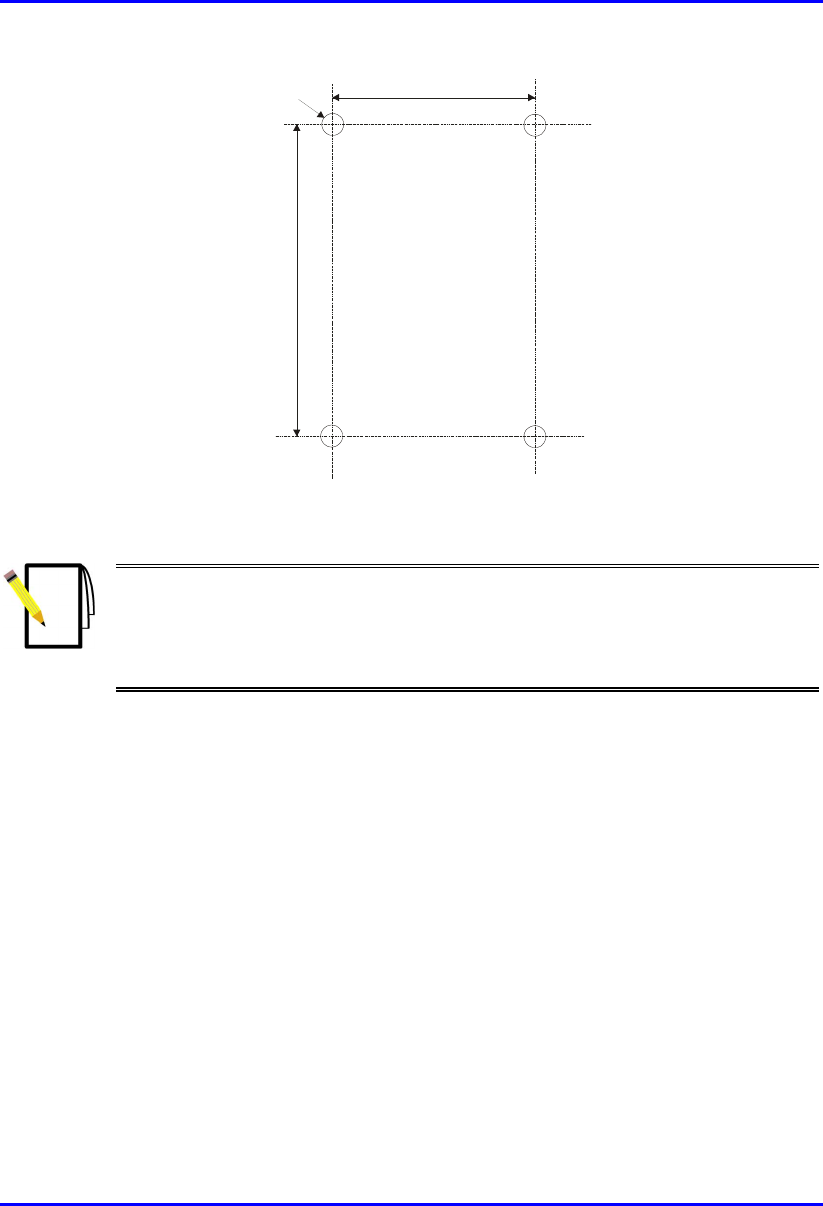
2. Attach the mounting bracket to the wall using four screws. The fixing
dimensions for the mounting bracket is illustrated in Figure 8-7.
Installing the SPR Hardware Installation Guide
8-10 Airspan Networks Ltd. 02030311-05
.
58mm
8mm
99mm
Figure 8-7: SPR mounting bracket dimensions for the four fixing holes
Note: Airspan does not provide screws for attaching the mounting bracket to
the wall. The screw size depends on the structure of the building to which the
bracket is to be attached. When selecting screw sizes, consideration must be
given to the weight of the SPR and load that may be induced in windy
conditions.
Hardware Installation Guide Installing the SPR
02030311-05 Airspan Networks Ltd. 8-11
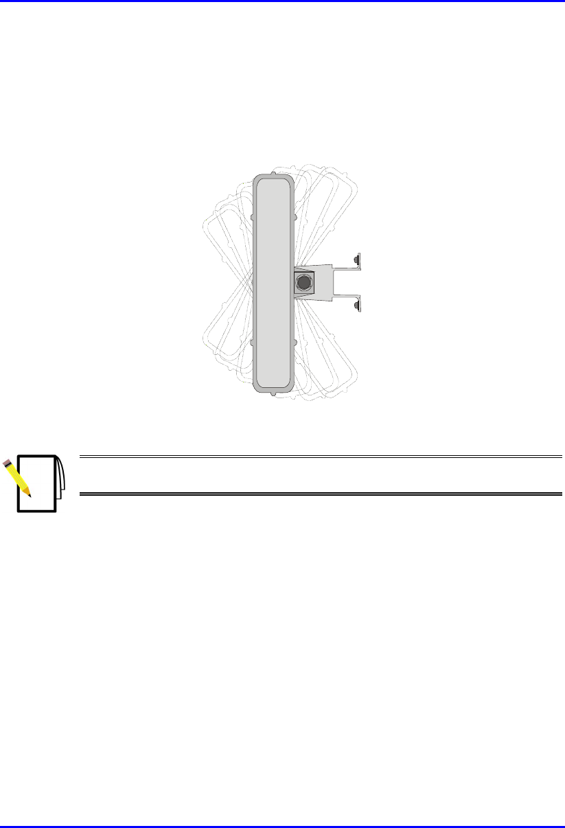
3. Adjust the horizontal positioning of the SPR, and then fasten tight the two
stainless-steel bolts.
Rotation is restricted to the horizontal plane only. The permissible rotation is
shown in Figure 8-8.
Figure 8-8: Horizontal rotation of the SPR
Note: A thread-locking compound is to be used to prevent the bolts working
loose.
Installing the SPR Hardware Installation Guide
8-12 Airspan Networks Ltd. 02030311-05
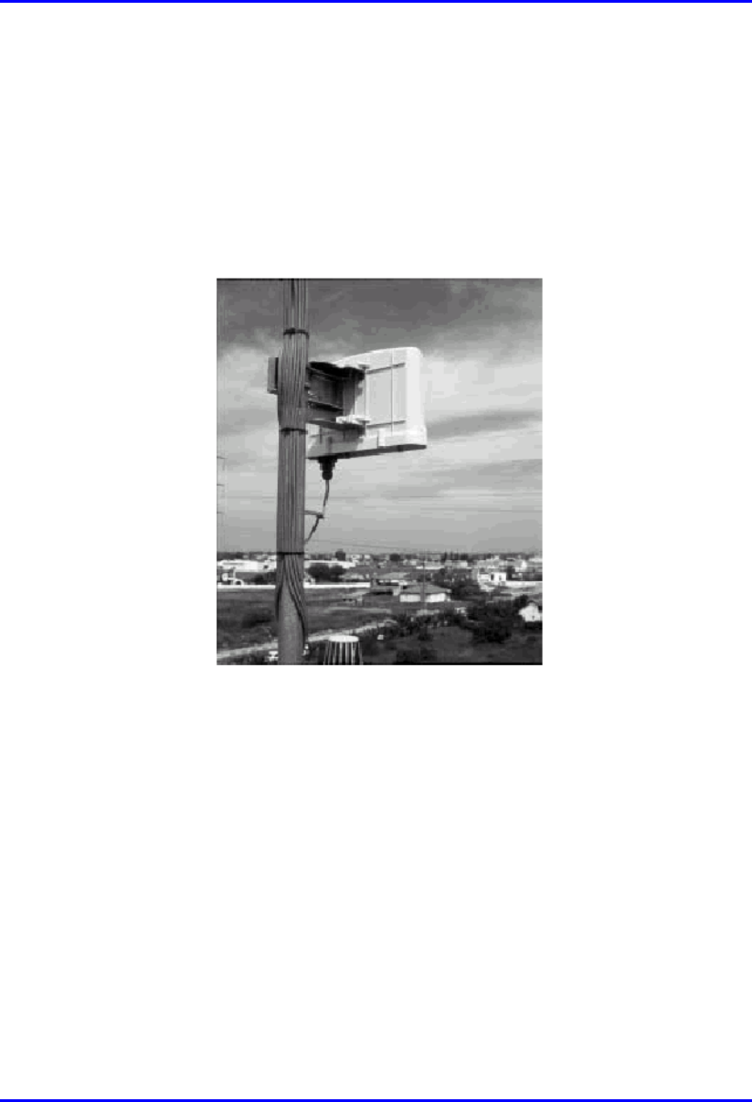
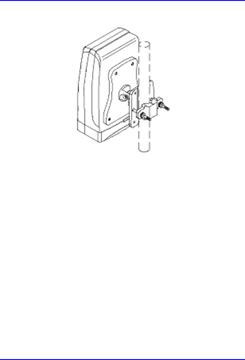
8.4.3. Pole-Mounting
The SPR can be mounted on a pole (see Figure 8-9). Pole mounting allows the SPR
to be adjusted in the horizontal as well as the vertical plane. The pole-mounting
bracket assembly is designed to support the SPR on a round pole of 45 mm in
diameter.
Figure 8-9: Mounted SPR
Hardware Installation Guide Installing the SPR
02030311-05 Airspan Networks Ltd. 8-13
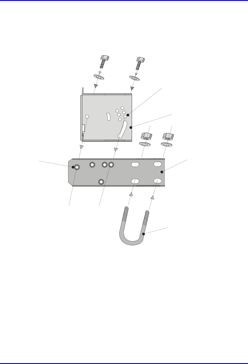
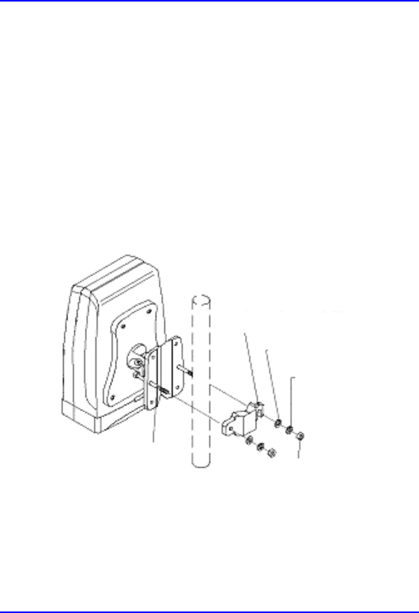
To mount the SPR on a pole:
1. Attach the mounting bracket to the SPR using two stainless steel bolts.
Pivot Hole
‘U’ Bolt
Locking Holes
BSR mounting
Bracket
Clamping Bracket
Figure 8-10: SPR mounting bracket assembly
2. Attach the clamping bracket to the mounting bracket using two M8 stainless
bolts.
3. Attach the Clamping bracket to the pole by placing the U-bolt around the pole,
and then inserting the U-bolt through the Clamping bracket and securing it by
screwing the two bolts on the U-bolt.
Installing the SPR Hardware Installation Guide
8-14 Airspan Networks Ltd. 02030311-05
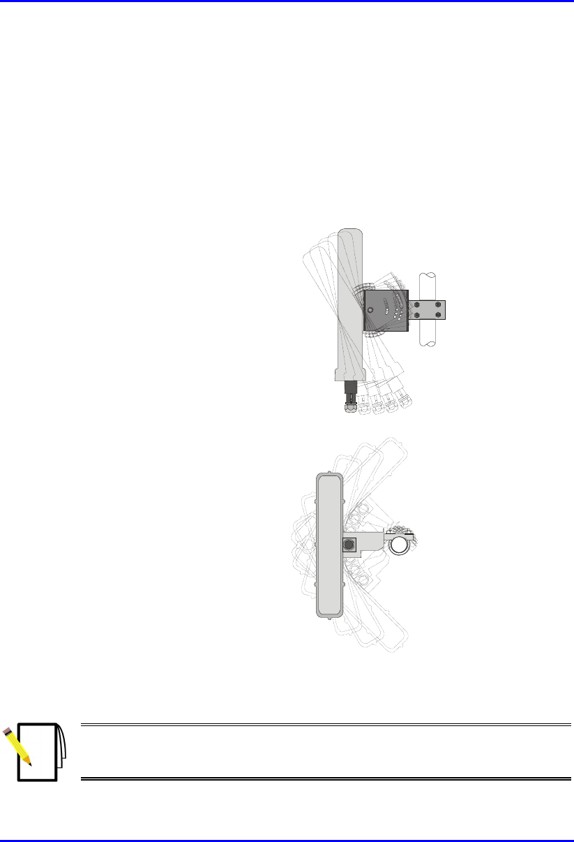
4. Adjust the vertical position of the SPR. Lock the SPR at the desired position by
inserting the locking bolt in the desired position. Once the correct angle has been
set both bolts must be tightened to lock the SPR bracket in place.
5. Adjust the horizontal position of the SPR by rotating the SPR about the pole, and
then tighten the U-bolt.
SPR positioning is obtained in two planes by adjustment of the mounting bracket
assembly a shown in Figure 8-11.
Rotation about the
mounting pole
Rotation about the
mounting bracket
Figure 8-11: SPR GPS orientation in vertical (top figure) and horizontal plane (lower
figure)
Note: A thread-locking compound is to be used to prevent the bolts working
loose. A loop should be left in the cable for maintenance purposes and to
prevent the cable weight being taken directly on the connector.
Hardware Installation Guide Installing the SPR
02030311-05 Airspan Networks Ltd. 8-15
8.5. Connecting a Third-Party External Antenna
(Optional)
The SPR model with an N-type connector can be connected to an external antenna.
The addition of an external antenna allows greater RF sector coverage than the
standard SPR internal antenna models (i.e., 60°).
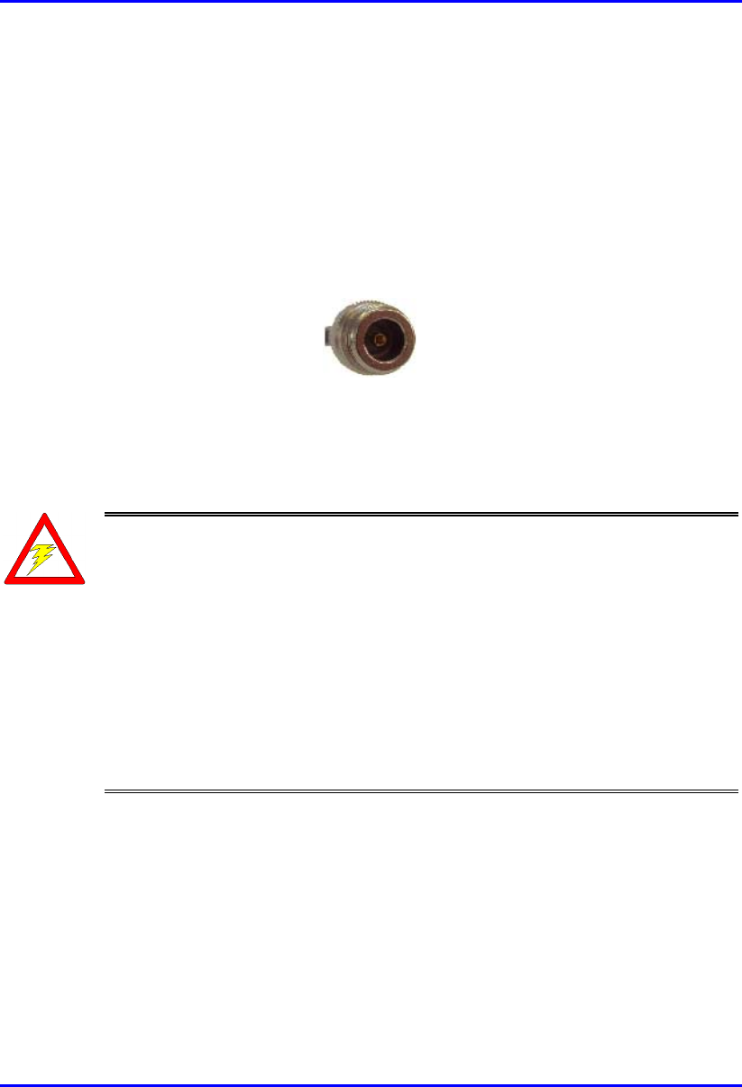
! Connector: N-type male
Figure 8-12: Example of an N-type connector
! Cable: RF coaxial
Warnings:
1) Before connecting the external antenna, ensure that the SPR is NOT
connected to the power source.
2) Before powering on the SPR, ensure that some type of equiment such as
an antenna or an RF attenuator is connected to the N-type receptacle. This
eliminates the risk of burning the SPR device.
3) It is the responsibility of the person installing the WipLL system to ensure
that when using the outdoor antenna kits in the United States (or where FCC
rules apply), that only those antennas certified with the product are used. The
use of any antenna other than those certified with the product is expressly
forbidden in accordance with FCC rules CFR47 part 15.204. The installer
should configure the output power level of antennas according to country
regulations and per antenna type
Installing the SPR Hardware Installation Guide
8-16 Airspan Networks Ltd. 02030311-05
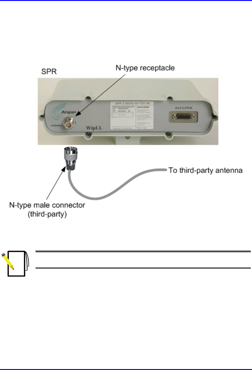
To connect the SPR to an external antenna:
! Attach an N-type male connector of the third-party antenna to the N-type
receptacle located on the SPR’s front panel.
Figure 8-13: SPR model with N-type connector for attaching an external antenna
Note: Airspan supplies unterminated cables for N-type connectors. Refer to
Appendix B, “Cable Crimping" for N-type cable crimping.
Hardware Installation Guide Installing the SPR
02030311-05 Airspan Networks Ltd. 8-17
8.6. Connecting to the SDA
The SPR connects to the subscriber’s PCs/network through the SDA. To connect the
SPR to the SDA, you need to connect the SPR’s 15-Pin D-type port to the SDA’s
15-pin D-type port by a CAT-5e cable.
The SPR-to-SDA cable connection configurations is as follows:
! Connectors:
! SPR: 15-pin D-type male (only 8 pins are used)
! SDA: 15-pin D-type male (only 8 pins are used)
Note: Airspan supplies unterminated CAT-5e cables. Refer to the cable
crimping procedures for 15-Pin D-type connectors detailed in Appendix B,
“Cable Crimping".
! Cable: straight-through 10Base-T Ethernet UTP 4 Pair CAT-5e outdoor type
(24 AWG)
! Connector pinouts:
Table 8-2: SPR-to-SDA CAT 5 cable connector pinouts
SPR SDA 15-pin
D-type
male Pin Function
Wire color Wire
pair Pin Function
1 +48 VDC Blue / white 1 +48 VDC
2 -48 VDC Blue
1
2 -48 VDC
3 Tx+ Orange / white 3 Rx+
4 Tx- Orange
2
4 Rx-
5 Rx+ Green / white 5 Tx+
6 Rx- Green
3
6 Tx-
7 Sync.+ Brown / white 7 Sync.+
8 Sync.- Brown
4
8 Sync.-
Installing the SPR Hardware Installation Guide
8-18 Airspan Networks Ltd. 02030311-05
Notes:
- Pins 9 through 15 of the 15-pin D-type connector are not used.
- The wire color-coding described in the table is WipLL's standard for wire
color-coding. However, if you implement your company's wire color-coding
scheme, ensure that the wires are paired and twisted according to the pin
functions listed in Table 8-2 (e.g., Rx+ with Rx-).
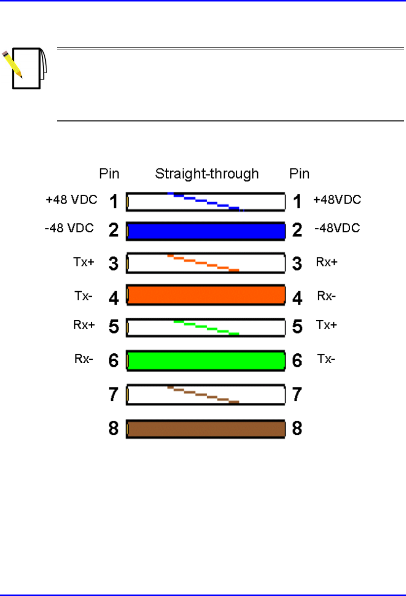
WipLL uses the following wire color-coding standards for CAT 5 cables with 15-pin
D-type to 15-pin D-type connectors on either ends (8 wires used):
Figure 8-14: WipLL wire color-coding for 15-pin D-type connectors
Hardware Installation Guide Installing the SPR
02030311-05 Airspan Networks Ltd. 8-19
Notes:
1) The wires are twisted together in pairs, for example, blue/white with blue,
and orange/white with orange. This prevents electrical interference between
the transmitter pins. For example, pin 3 (Tx+; orange / white) is paired and
twisted with pin 4 (Tx-; orange).
2) The SDA connector pinouts are the same for all SDA models (SDA-1, SDA-
4H, SDA-4S, SDA-4S/VL, SDA-4S/Vltag, SDA-4S/1H3L, and SDA-
4S/VL/1H3L).
Warning: To avoid electrical shock, before connecting the SPR to the SDA,
ensure that the SDA is not connected to the power supply.
To connect the SPR to the SDA:
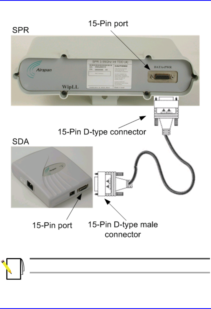
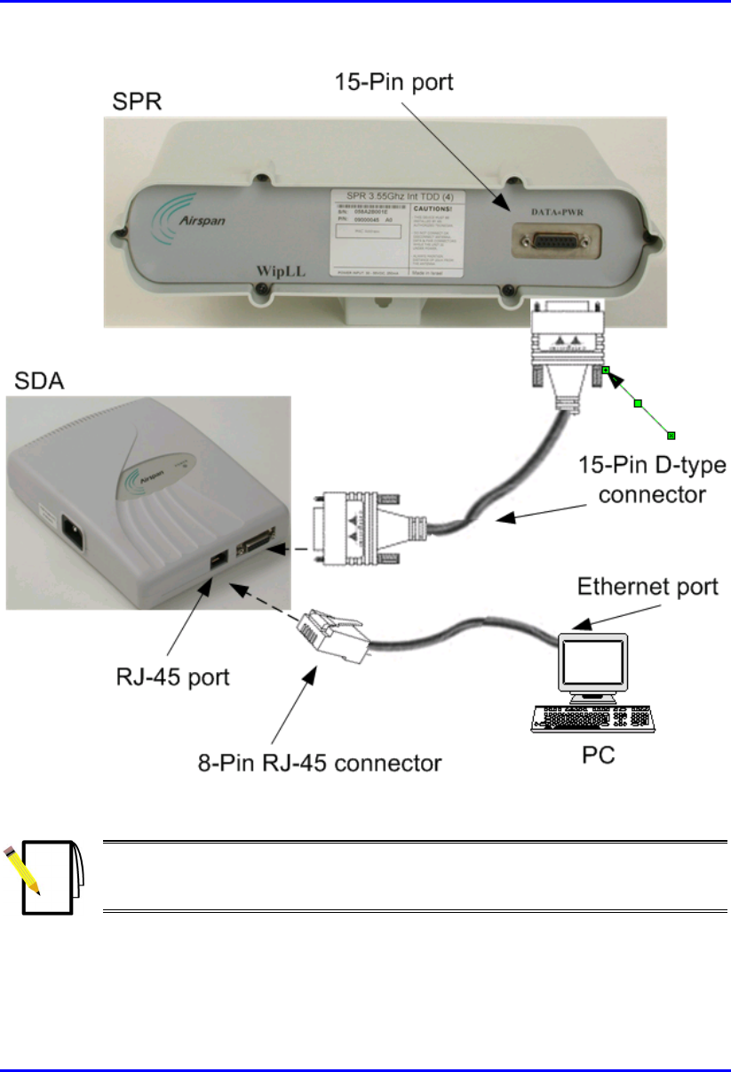
1. Attach the 15-pin D-type connector, at one end of the cable, to the SPR’s 15-pin
D-type port labeled DATA POWER SYNC, as displayed in Figure 8-15.
2. Attach the 15-pin D-type connector, at the other end of the cable, to the SDA’s
15-pin D-type port, as displayed in Figure 8-15.
Installing the SPR Hardware Installation Guide
8-20 Airspan Networks Ltd. 02030311-05
Figure 8-15: SPR-to-SDA cable connections
Note: The maximum cable length permissible between the SPR and SDA is
100 meters.
Hardware Installation Guide Installing the SPR
02030311-05 Airspan Networks Ltd. 8-21
8.7. Connecting to a PC for Serial Configuration
To configure an SPR, you need to connect a PC running the WipLL network
management system (WipConfig) to the SPR. The SPR’s 15-pin D-type port
provides serial interface to a PC for SPR initial configuration. This port uses 9 of its
15 pins for serial interface; the remaining pins are used for interfacing with the SDA
with which the SPR remains connected. To connect the SPR to the management
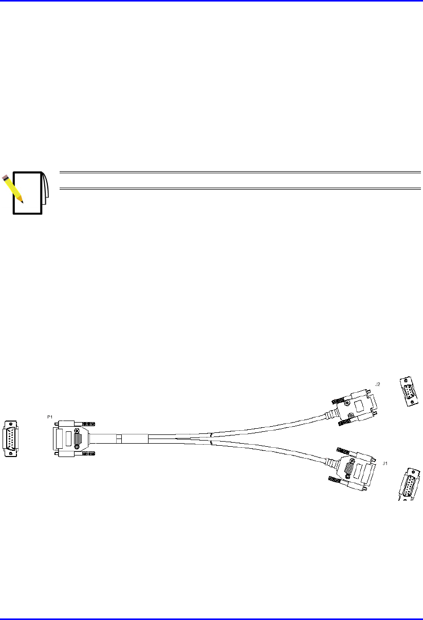
station (i.e., PC) and the SDA, a Y-cable (splitter) is used.
Note: SPR configuration is performed while the SDA is connected to the SPR.
The SPR-to-PC and SDA cable connections for SPR serial configuration are as
follows:
! Connectors:
! SPR: 15-pin D-type male (only 9-pins used)
! PC: 9-pin D-type (RS-232)
! SDA: 15-pin D-type male
! Cable: straight-through Y-cable
Figure 8-16: Y-cable for serial connection
15-pin D-type
male
PC
SDA
15-pin D-type
male
9-pin D-type
female
SPR
Installing the SPR Hardware Installation Guide
8-22 Airspan Networks Ltd. 02030311-05
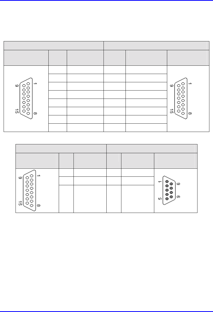
! Connector pinouts:
Table 8-3: Y-cable SPR-to-SDA connector pinouts
SPR SDA
15-pin D-type
male
Pin Function Pin Function 15-pin D-type
male
1 0 VDC 1 +48 VDC
2 +48 VDC 2 -48 VDC
3 Ethernet Tx+ 3 Rx+
4 Ethernet Tx- 4 Rx-
5 Ethernet Rx+ 5 Tx+
6 Ethernet Rx- 6 Tx-
7 Hop Sync+ 7 Sync.+
8 Hop Sync- 8 Sync.-
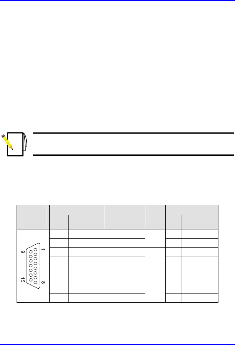
Table 8-4: Y-cable SPR-to-PC connector pinouts
SPR PC
15-pin D-type
male
Pin Function Pin Function 9-pin D-type
female
12 GND 5 GND
14 RS232 Rx 3 Rx
15 RS232 Tx 2 Tx
Hardware Installation Guide Installing the SPR
02030311-05 Airspan Networks Ltd. 8-23
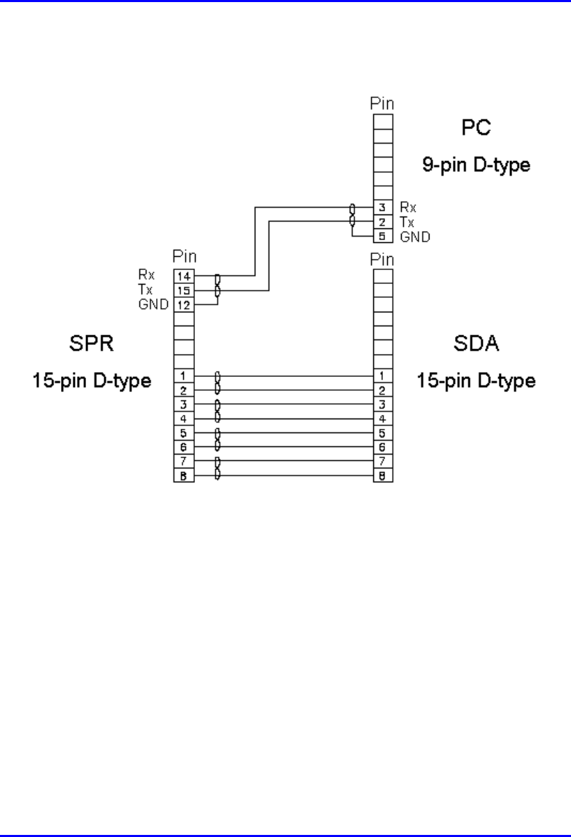
The Y-cable connector pin assignments are displayed shematically in Figure 8-17.
Figure 8-17: Y-cable connector pin assignment
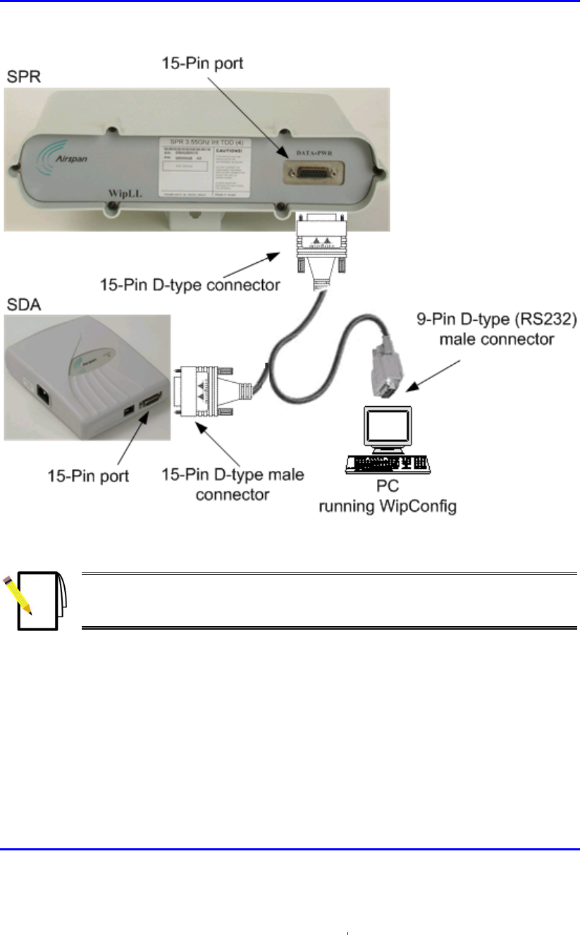
To connect the SPR to a PC for serial configuration:
1. Connect the 15-pin D-type male connector (P1), at the one end of the Y-cable,
to the SPR, as displayed in Figure 8-18.
2. Connect the 15-pin D-type male connector (J1), at the other end of the Y-cable,
to the SDA, as displayed in Figure 8-18.
3. Connect the 9-pin D-type (RS232) connector (J2), at the other end of the Y-
cable, to the PC, as displayed in Figure 8-18.
Installing the SPR Hardware Installation Guide
8-24 Airspan Networks Ltd. 02030311-05
Figure 8-18: SPR cable connections for serial configuration
Note: For performing SPR initial configuration using WipLL’s management
applications, refer to Airspan’s WipConfig User’s Guide or WipConfig PDA
User’s Guide.

Hardware Installation Guide Installing the SPR
02030311-05 Airspan Networks Ltd. 8-25
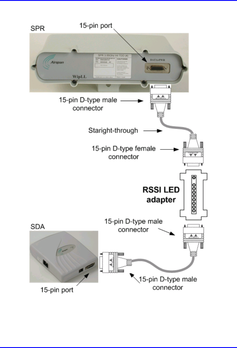
8.8. Connecting the RSS LED Adapter
The WipLL RSS LED adapter indicates the received signal strength (RSS) between
the SPR and the BSR. This allows you to accurately position the SPR during
installation for optimal radio frequency signal reception. The RSS LED adapter is
connected between the SPR and SDA CAT 5 cable connection. The RSS LED
adapter provides two 15-pin D-type ports: one for the SPR side; and the other for the
SDA side. The RSS LED adapter can be connected in one of the following manners:
! The RSS LED adapter 15-pin D-type port connects directly to the SPR’s 15-pin
D-type port; while the other RSS LED adapter’s 15-pin D-type port connects to
the SDA via the CAT 5 cable.
-Or-
! Both 15-pin D-type ports of the RSS LED adapter connect to the SPR and SDA
via a CAT 5 cable on either side.
The following describes the connectors, cable, and connector pinouts:
! Connectors:
! SPR: 15-pin D-type male (only 9-pins used)
! RSS LED adapter:
− SPR side: 15-pin D-type female
− SDA side: 15-pin D-type male
! SDA: 15-pin D-type male
! Cables: two straight-through cables for SPR-to-RSS LED adapter, and for SDA-
to-RSS LED adapter.

Installing the SPR Hardware Installation Guide
8-26 Airspan Networks Ltd. 02030311-05
To connect the RSSI LED adapter:
1. Connect the 15-pin D-type male connector, at one end of the straight-through
cable, to the SPR, as displayed in Figure 8-19.
2. Connect the 15-pin D-type female connector, at the other end of the straight-
through cable, to the RSS LED adapter, as displayed in Figure 8-19.
3. Connect the 15-pin D-type male connector, at one end of the straight-through
cable that originates from the SDA, to the RSS LED adapter, as displayed in
Figure 8-19.
Hardware Installation Guide Installing the SPR
02030311-05 Airspan Networks Ltd. 8-27
Figure 8-19: Connecting the RSS LED adapter
Installing the SPR Hardware Installation Guide
8-28 Airspan Networks Ltd. 02030311-05
Note: You can connect the RSS LED adapter’s 15-pin male port directly to the
SPR’s 15-pin port, instead of using a cable.
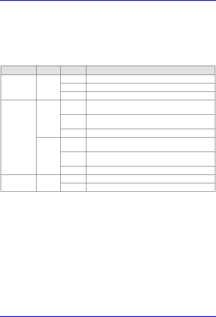
Table 8-5 describes the LEDs on the RSS LED adapter.
Table 8-5: LED description of the RSS LED adapter
LED Color Function Status Description
On The SPR receives power from
the SDA
Off No power is supplied to the
SPR by the SDA
Power Red Power
Blinking Data transmission is occurring
on the Ethernet LAN
LED 1 blinking RSS ≤ -94 dBm
LED 1 is on -93 dBm ≤ RSS ≤ -90 dBm
LEDs 1 and 2 are
on
-89 dBm ≤ RSS ≤ -86 dBm
LEDs 1, 2, and 3
are on
-85 dBm ≤ RSS ≤ -82 dBm
LEDs 1, 2, 3, and 4
are on
-81 dBm ≤ RSS ≤ -78 dBm
LEDs 1, 2, 3, 4,
and 5 are on
-77 dBm ≤ RSS ≤ -74 dBm
LEDs1, 2, 3, 4, 5,
and 6 are on
-73 dBm ≤ RSS ≤ -70 dBm
LEDs 1, 2, 3, 4, 5,
6 and 7 are on
-69 dBm ≤ RSS ≤ -66 dBm
RSS LEDs
(LEDs 0 to 7)
Green Received
Signal
Strength
level
All LEDs are on RSS ≥ -65 dBm
Hardware Installation Guide Installing the SPR
02030311-05 Airspan Networks Ltd. 8-29
8.9. Connecting Power
The SPR receives, through its 15-pin D-type port, its power supply from the SDA.
In turn, the SDA connects to an external power adapter from where it receives
power. The SDA provides 48 VDC nominal power to the SPR (minimum of 30
VDC: maximum of 55 VDC).
Warning: If you are using an external antenna, ensure that you connect the
antenna before connecting the SPR to the power source.
Note: For a description of the procedure for connecting power to the SDA, see
Chapter 9, “Installing the SDA”.

02030311-05 Airspan Networks Ltd. 9-1
Installing the SDA
Installing the SDAInstalling the SDA
Installing the SDA
This chapter describes the installation of the WipLL Subscriber Data Adapter
(SDA) at the subscriber's premises.
This chapter includes the following chapters:
! Overview
! Physical Dimensions and Basic Design
! Mounting the SDA
! Desktop-Mounting
! Wall-Mounting
! Connecting to the SPR
! Connecting to the Subscriber’s Ethernet Network
! Connecting to PCs
! Connecting to a Hub
! Connecting to a VoIP Network
! Connecting AC Power
! LED Display
! SDA-4H
! SDA-4S Models
9

Installing the SDA Hardware Installation Guide
9-2 Airspan Networks Ltd. 02030311-05
9.1. Overview
The SDA is an Ethernet hub/LAN switch that provides the SPR with DC power,
lightening protection, and Ethernet connectivity to the subscriber’s PCs/network.
The SDA connects to the SPR by a CAT-5 cable.
The SDA provides 10/100BaseT connectivity (depending on the SDA model) to the
subscriber’s PCs or network (up to four PCs depending on the SDA model).
The SDA is located inside the subscriber's premises, typically mounted on a wall or
simply placed on a desktop.
The SDA is available in six models:
! SDA-1: This is a hub that provides one 10BaseT interface (RJ-45 port) with the
subscriber’s PC and/or network (via a hub or LAN switch).
! SDA-4H: This is a hub and provides four 10BaseT ports for interfacing with the
subscriber’s PCs/network. In addition, one of the 10BaseT ports provides
crossover configuration for crossover-cable connection for interfacing with, for
example, other hubs.
! SDA-4S models: Integrated LAN switches, providing four 10/100BaseT
interfaces with the subscriber’s PCs/network. The ports of the SDA-4S models
support Auto Negotiation, allowing automatic configuration for the highest
possible speed link: 10BaseT or 100BaseT, and Full Duplex or Half Duplex
mode. In other words, the speed of the connected device (PC) determines the
speed at which packets are transmitted through the specific port. For example, if
the device (i.e, PC) to which the port is connected is running at 100 Mbps, the
port connection will transmit packets at 100 Mbps. If the device (i.e, PC) to
which the port is connected is running at 10 Mbps, the port connection will
transmit packets at 10 Mbps. In addition, the SDA-4S ports support MDI/MDI-
X automatic crossover, allowing connection to straight-through or crossover
CAT-5 cables
! SDA-4S (standard): Standard integrated LAN switch, providing four
10/100BaseT interfaces to the subscriber’s computers.
Hardware Installation Guide Installing the SDA
02030311-05 Airspan Networks Ltd. 9-3
! SDA-4S/VL: Provides VLANs between its ports and the SPR, ensuring
privacy between users of different ports (i.e., multi-tenant VLAN security).
For example, all users connected to Port 1 do not “see” users connected to
Port 2.
! SDA-4S/VLtag: This model is ideal for multi-tenant applications where
traffic engineering and privacy is required. SDA-4S/VLtag assigns the traffic
from each of its four ports with a different VLAN ID. The VLAN IDs are
fixed (since SDA-4S/VLtag is not user configurable). SPR converts the four
VLAN IDs tagged by SDA-4S/VLtag to four VLAN IDs configured via
WipLL’s NMS. The tag conversion is performed by SPR before sending the
traffic to the air and the other way around when coming from the air.
! SDA-4S/1H3L: Provides a high priority port (left-most port) for VoIP
traffic.
! SDA-4S/VL/1H3L: Combines the functionality of the SDA-4S/VL and
SDA-4S/1H3L models (VLAN for each port and a high priority port for
VoIP).
Figure 9-1 displays a typical setup of the SPR and SDA at the subscriber's premises.
Note: The SDA can also be installed at a base station that has only one BSR.
This SDA replaces the need for the BSDU, and provides power and
connectivity to the single BSR.
Installing the SDA Hardware Installation Guide
9-4 Airspan Networks Ltd. 02030311-05
RF link
CAT-5e
PC
Figure 9-1: Typical SPR and SDA location and connections at subscriber's premises
Subscriber Data
Adapter (SDA)
located inside
Subscriber Premises
Radio (SPR) located
on the roof
Hardware Installation Guide Installing the SDA
02030311-05 Airspan Networks Ltd. 9-5
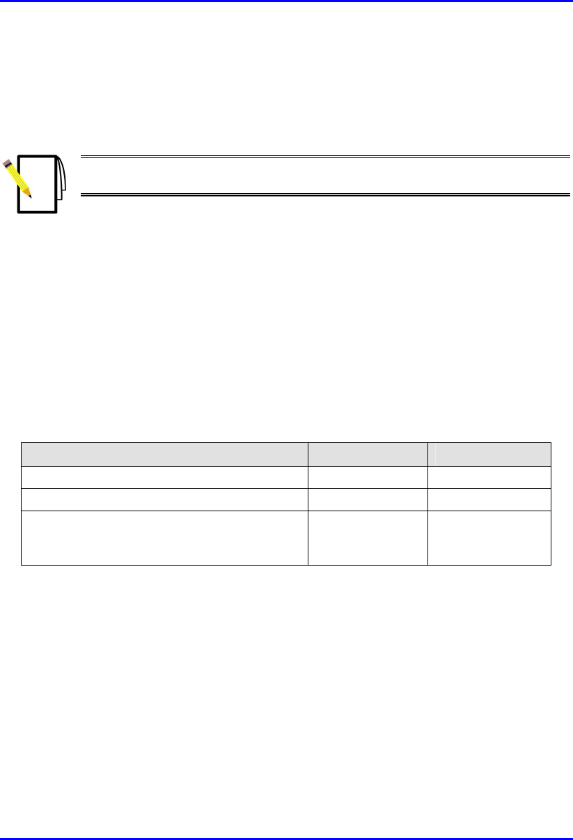
9.2. Physical Dimensions and Basic Design
The SDA is encased in a chassis. The chassis front panel provides access to the
SDA’s communication ports. The left-side of the chassis provides a power connector
port for connection to an external power adapter. The SDA’s bottom panel provides
holes for mounting the SDA on a wall
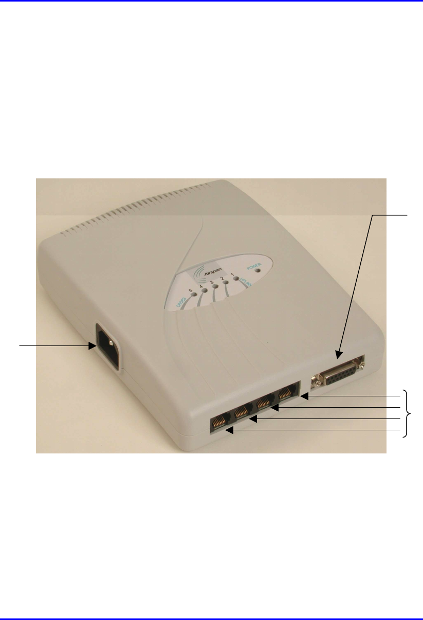
Figure 9-2 displays the SDA-4S models and the SDA-4H.
Figure 9-2: SDA-4S models and SDA-4H (front, side, and top panels)
15-pin D-type
p
ort
10/100BaseT
p
orts
Power
connector port
Installing the SDA Hardware Installation Guide
9-6 Airspan Networks Ltd. 02030311-05
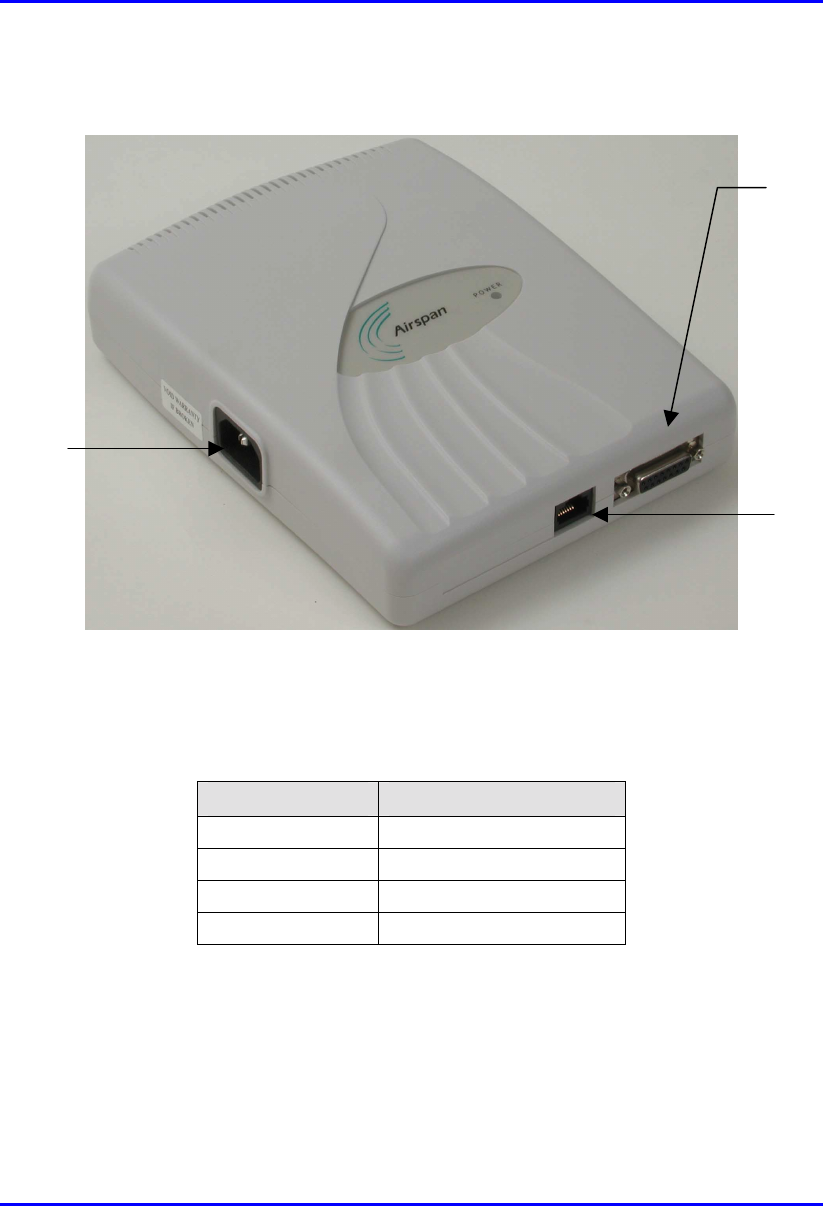
Figure 9-3 displays the SDA-1 model.
Figure 9-3: SDA-1 (front, side, and top panels)
The SDA’s physical dimensions are described in Table 9-1
Table 9-1: SDA physical dimensions
Parameter Value
Height 200 mm (7.87 inches)
Width 150 mm (5.9 inches)
Depth 40 mm (1.57 inches)
Weight 0.53 kg
15-Pin D-type
p
ort
RJ-45 port
(10BaseT)
Power connector
p
ort
Hardware Installation Guide Installing the SDA
02030311-05 Airspan Networks Ltd. 9-7
9.3. Mounting the SDA
The SDA can be wall or desk mounted.
9.3.1. Desktop-Mounting
For desk mounting (horizontal mounting), the chassis’ bottom panel provides four
rubber feet on each corner.
Warning: For desk mounting, do not place the SDA on a carpeted surface
where airflow is restricted and a fire hazard may result.
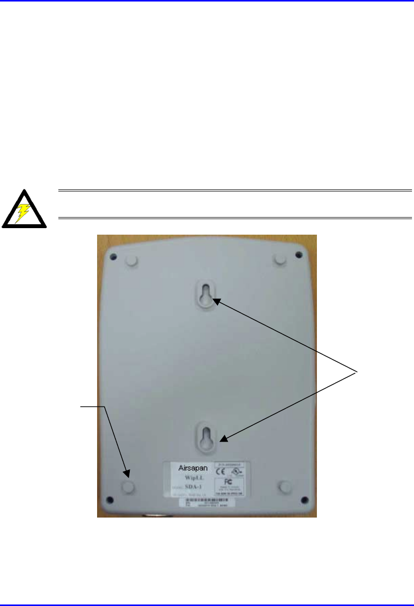
Figure 9-4: SDA - rear panel
Mounting
brackets
Rubber feet
Installing the SDA Hardware Installation Guide
9-8 Airspan Networks Ltd. 02030311-05
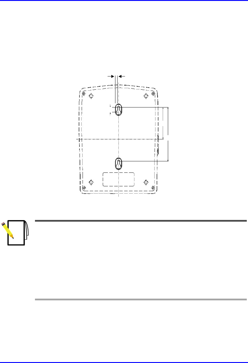
9.3.2. Wall-Mounting
For SDA wall mounting, two mounting hooks are molded into the chassis’ bottom
panel (see Figure 9-4). The dimensions of the SDA’s wall-mounting hooks, located
on the chassis bottom panel, are displayed in Figure 9-5.
5 mm
59
100
9
Figure 9-5: SDA mounting footprint details
Notes:
1) Airspan does not supply screws for wall mounting as the size and type o
f
screws depends on the type of wall at the subscriber’s premises
2) For reasons of safety both fixing points must be utilized when mounting the
unit.
3) The SDA is supplied with a 1-metre AC power lead assembly. Therefore,
the unit must be located within reachable distance of the customer's mains
power outlet.
4) The cable must be dressed tidily and not be taught or pose a trip hazard
when connected.
5) The maximum cable run between an SDA and an SPR is 100 meters.
Hardware Installation Guide Installing the SDA
02030311-05 Airspan Networks Ltd. 9-9
9.4. Connecting to the SPR
The SDA’s 15-pin D-type port connects to the SPR’s 15-pin D-type port by a CAT-
5 cable.
Note: For a detailed description on connecting the SDA to the SPR, see
Chapter 8, “Installing the SPR”.
9.5. Connecting to the Subscriber’s Ethernet
Network
The SDA provides RJ-45 port(s) for Ethernet connectivity to the subscriber’s
PCs/network. The number of Ethernet ports and the speed of the Ethernet connection
depend on the SDA model. Table 9-2 describes the number of ports and
transmission speeds supported by the various SDA models.
Table 9-2: Number of ports and transmission speed of SDA models
SDA Model RJ-45 Ports Speed (Mbps)
SDA-1 1 10
SDA-4H 4 10
SDA-4S models
(SDA-4S; SDA-4S/VL; SDA-4S/Vltag; SDA-
4S/1H3L; SDA-4S/VL/1H3L)
4 10/100
Installing the SDA Hardware Installation Guide
9-10 Airspan Networks Ltd. 02030311-05
The following list describes the location of the Ethernet ports for the various SDA
models:
! SDA-1: one RJ-45 port (see Figure 9-6)
Figure 9-6: SDA-1 with one Ethernet port
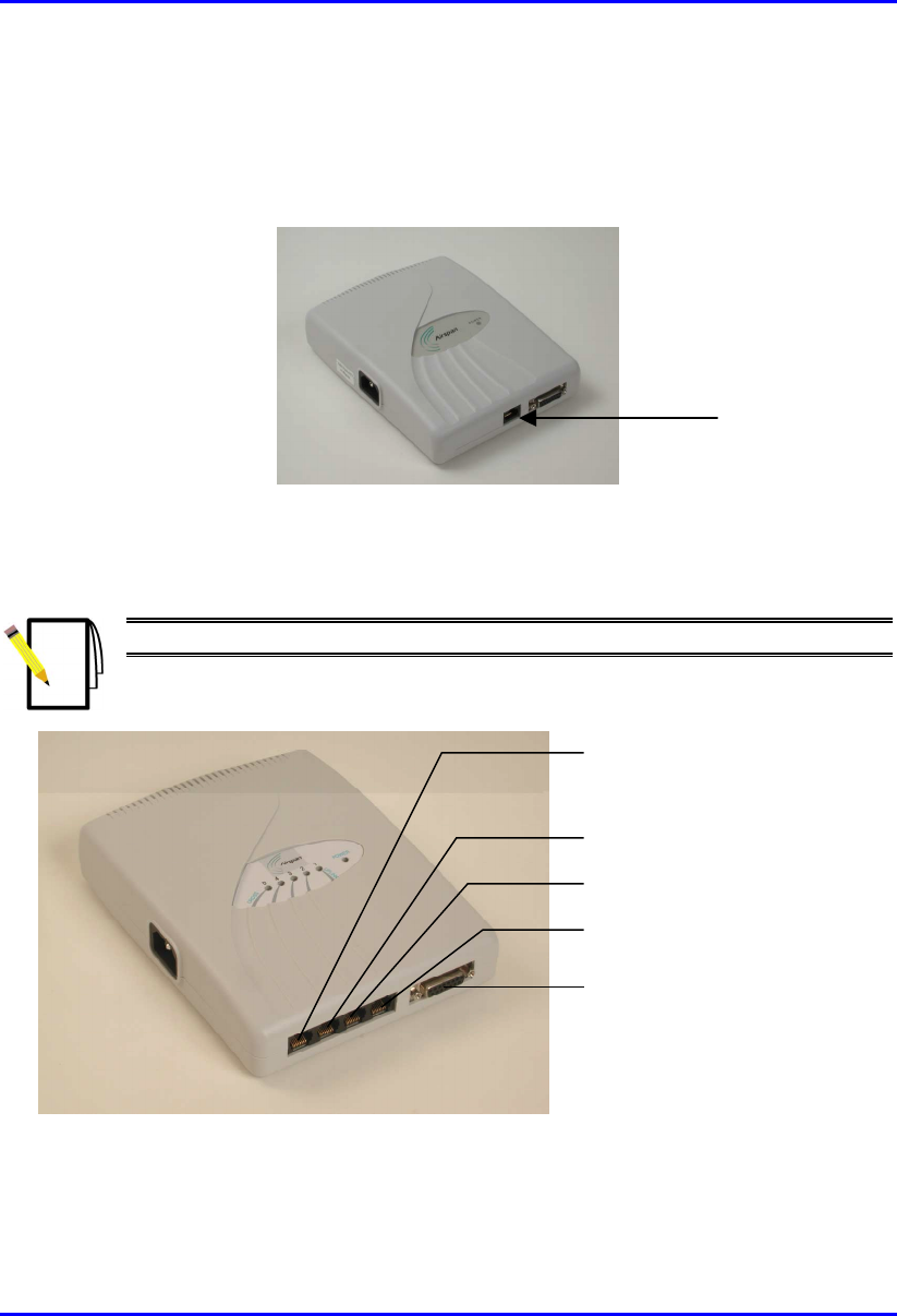
! SDA-4H: four RJ-45 ports (see Figure 9-7).
Note: The left-most port (J5) is a crossover port.
R-J45 connector (J5)
- cross over
R
-J45 connector
(
J4
)
R-J45 connector (J3)
R-J45 connector (J2)
D-type connector (J1)
Figure 9-7: SDA-4H with four Ethernet ports
RJ-45 port
Hardware Installation Guide Installing the SDA
02030311-05 Airspan Networks Ltd. 9-11
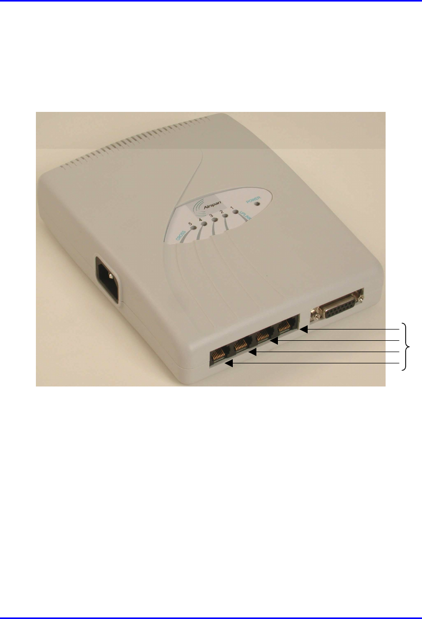
! SDA-4S models (SDA-4S, SDA-4S/VL, SDA-4S/Vltag, SDA-4S/1H3L, and
SDA-4S/VL/1H3L): four 10/100BaseT RJ-45 ports. These ports support 10/100
Mbps autonegotiation, and MDI/MDI-X automatic crossover. This allows you to
connect straight-through or crossover CAT-5 cables to these ports.
Figure 9-8: SDA-4S RJ-45 Ethernet Ports
10/100BaseT
RJ-45 ports
Installing the SDA Hardware Installation Guide
9-12 Airspan Networks Ltd. 02030311-05
9.5.1. Connecting to PCs
The SDA connects to the subscriber’s PC(s) through the SDA’s Ethernet port
(RJ-45).
Note: To avoid electrical or fire hazard, ensure that the data connections to
the SDA is made prior to connecting the power supply.
The SDA-to-subscriber PC cable configurations are as follows:
! Connector: 8-pin RJ-45
! Cable: straight-through Ethernet cable
! Connector Pinouts:
RJ-45:
SDA-1, SDA-4H (J2, J3, J4), SDA-4S
RJ-45 crossover cables:
SDA-4H (J5)
Pin Function Pin Function
1 +RX 1 +Tx
2 -RX 2 -Tx
3 +TX 3 +Rx
4
N
C4
N
C
5
N
C5
N
C
6 -TX 6 -Rx
7
N
C7
N
C
8
N
C8
N
C
To connect the SDA to the subscriber’s PC(s):
1. Connect the 8-pin RJ-45 male connector, at the one end of the Ethernet cable, to
the SDA’s RJ-45 Ethernet port (see Figure 9-9).
2. Connect the
8-pin RJ-45 male connector, at the other end of the Ethernet cable,
to the subscriber’s PC (or device). (See Figure 9-9.)
Hardware Installation Guide Installing the SDA
02030311-05 Airspan Networks Ltd. 9-13
Figure 9-9: SDA-to-PC Cable Connections
Note: The SDA-4S RJ-45 ports support MDI/MDI-X automatic crossover. This
means that straight-through or crossover CAT-5 cables can be connected to
these ports.
Installing the SDA Hardware Installation Guide
9-14 Airspan Networks Ltd. 02030311-05
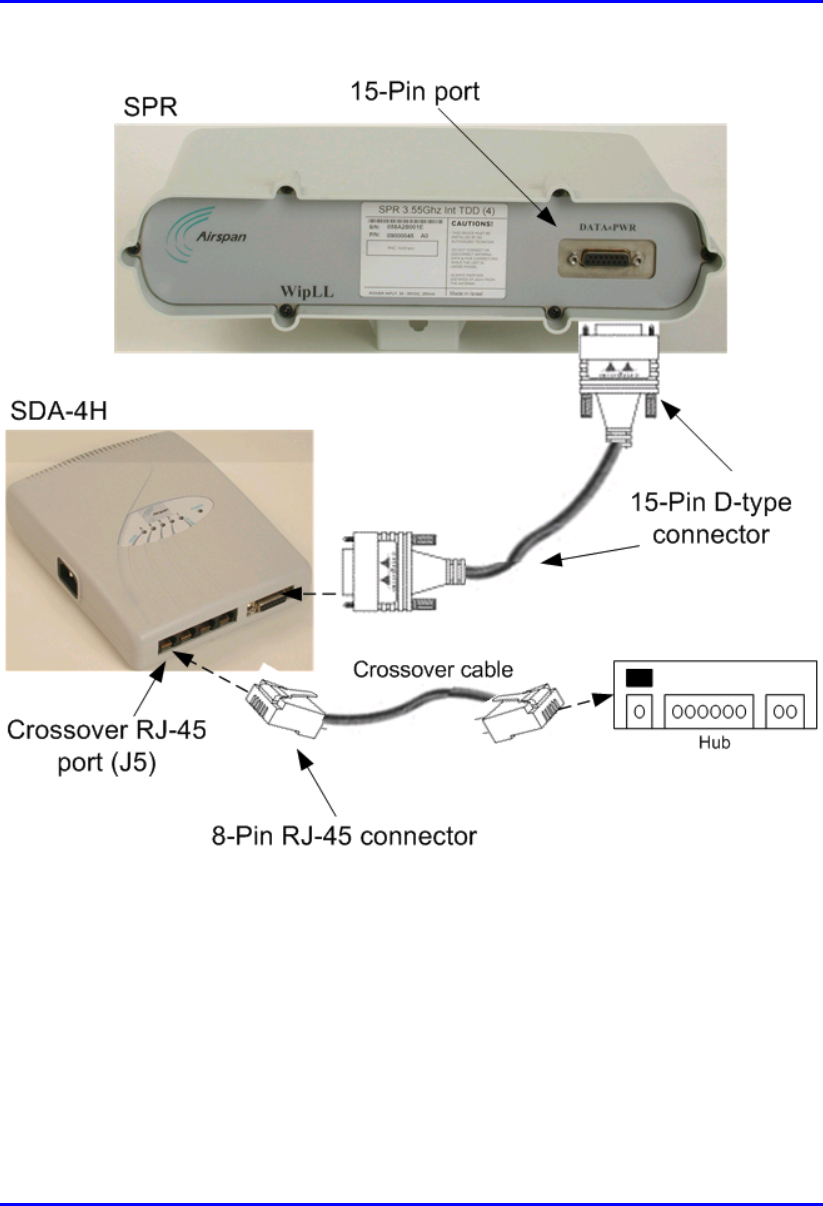
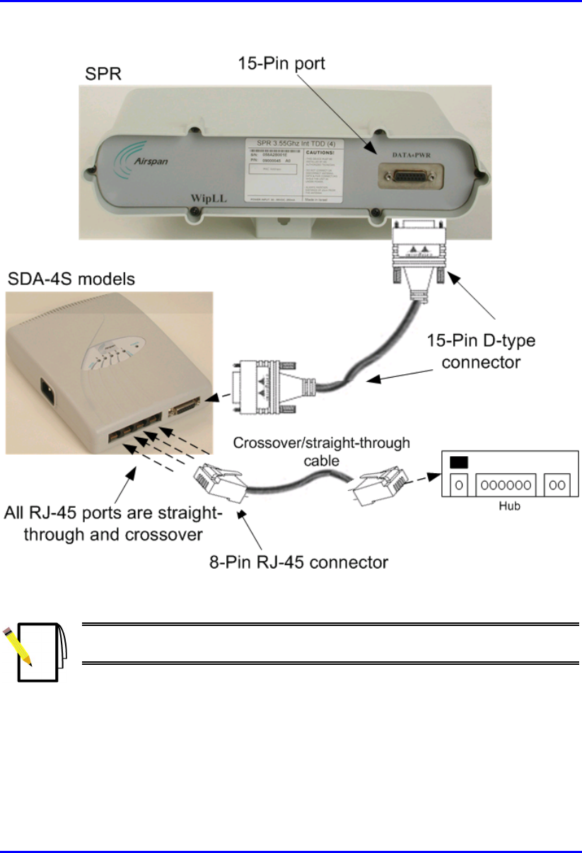
9.5.2. Connecting to a Hub
The SDA-4S models and SDA-4H can be connected to another hub (for example,
for daisy chaining). The ports of the SDA-4S models support MDI/MDI-X
automatic crossover, allowing connection of straight-through or crossover cables.
However, for the SDA-4H model, only the left-most RJ-45 port (J5) is a crossover
port (see Figure 9-7).
The SDA-4S and SDA-4H cable configurations for connectivity to a hub, are as
follows:
! Connector: 8-Pin RJ-45
! Cable:
! SDA-4H: crossover-cable
! SDA-4S models: straight-through or crossover cables (due to MDI/MDI-X
ports)
! Connector pinouts: SDA-4H:
SDA-4H
RJ-45 (J5)
Pin Function
1+TX
2-TX
3+RX
4
N
C
5
N
C
6-RX
7
N
C
8
N
C
To connect SDA-4S or SDA-4H to a hub:
1. Connect the RJ-45 male, at one end of the cable, to the SDA-4H’s left-most RJ-
45 port (J5), or any SDA-4S’s RJ-45 port.
2. Connect the RJ-45 male, at the other end of the cable, to the hub.
Hardware Installation Guide Installing the SDA
02030311-05 Airspan Networks Ltd. 9-15
Figure 9-10: SDA-4H crossover cable connections to hub
Installing the SDA Hardware Installation Guide
9-16 Airspan Networks Ltd. 02030311-05
Figure 9-11: SDA-4S crossover/straight-through cable connections to hub
Note: The SDA-4S RJ-45 ports support MDI/MDI-X automatic crossover.
Therefore, crossover CAT-5 cables can be connected to any of the ports.

Hardware Installation Guide Installing the SDA
02030311-05 Airspan Networks Ltd. 9-17
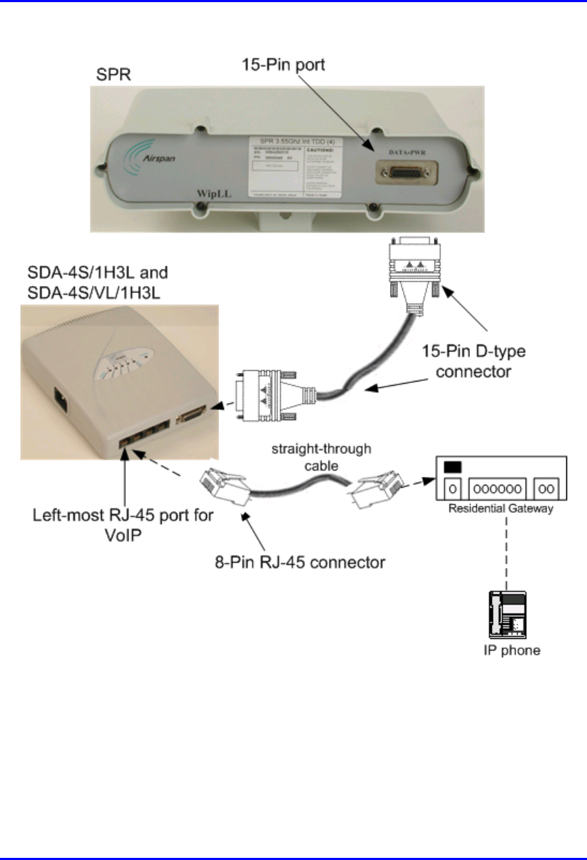
9.5.3. Connecting to a VoIP Network
The SDA-4S/1H3L and SDA-4S/VL/1H3L model’s left-most RJ-45 Ethernet port
assigns high priority to VoIP trafic. This port is used to connect to the subscriber’s
VoIP network. This port assigns high priority to VoIP traffic, as opposed to the other
RJ-45 ports, which assigns lower priority.
The cable connections for connecting the SDA-4S/1H3L and SDA-4S/VL/1H3L
models to the subscriber’s VoIP network, are as follows:
! Connector: 8-pin RJ-45 male
! Cable: straight-through or crossover
! Connector pinouts:
RJ-45 (left-most port)
Pin Function
1 +RX
2 -RX
3 +TX
4
N
C
5
N
C
6 -TX
7
N
C
8
N
C
To connect to the VoIP network:
1. Connect the RJ-45 male connector, at the one end of the Ethernet cable, to the
left-most RJ-45 port on the front panel of the SDA-4S/1H3L and SDA-
4S/VL/1H3L chassis (see Figure 9-12).
2. Connect the RJ-45 male connector, at the other end of the cable, to the VoIP
network, for example, to a Residential Gateway (see Figure 9-12).
Installing the SDA Hardware Installation Guide
9-18 Airspan Networks Ltd. 02030311-05
Figure 9-12: Connecting VoIP RJ-45 Port (for SDA-4S/1H3L and SDA-4S/VL/1H3L)
Hardware Installation Guide Installing the SDA
02030311-05 Airspan Networks Ltd. 9-19
9.6. Connecting AC Power
The SDA receives AC power by connecting to a standard 110–240 VAC wall outlet.
In turn, the SDA provides 48 VDC nominal power to the SPR (minimum of 30
VDC: maximum of 55 VDC).
Table 9-3 lists the SDA power supply specifications.
Table 9-3: SDA Power Supply Specifications
Power parameter Units
Voltages 110-240 VAC
Frequency 50/60 Hz
Amps 0.3-0.7A
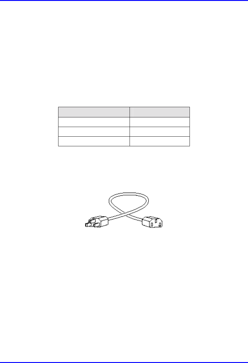
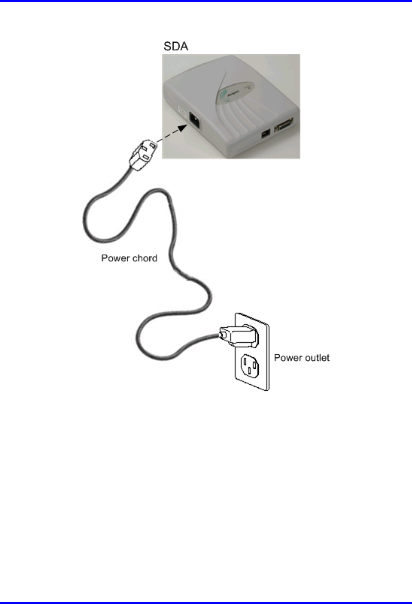
The following lists the cable connection between the SDA and the power outlet:.
! Connector: AC IEC 320 type (female)
Figure 9-13: Power Chord
! Cable: 3-core 0.7mm² type (maximum length is 1.5 m)
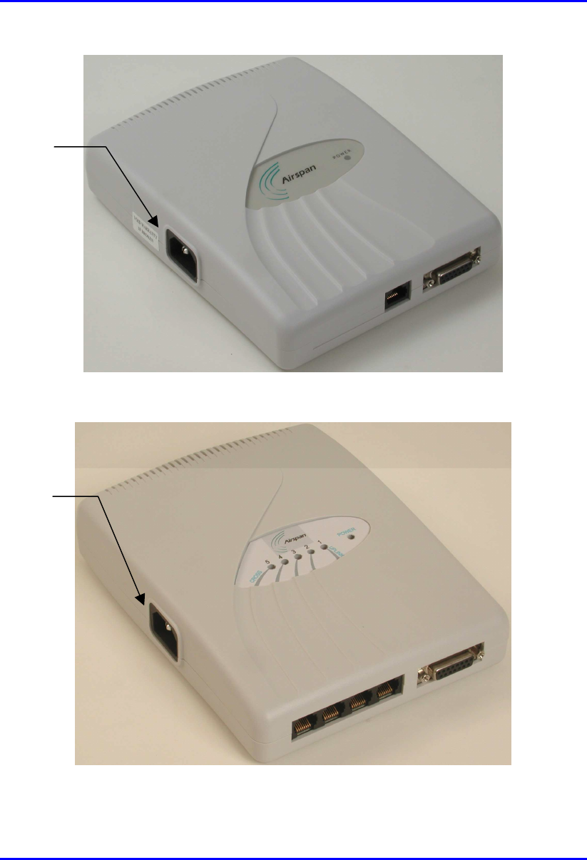
For all SDA models, the power port is located on the left-panel of the chassis, as
displayed in Figure 9-14 for SDA-1, and in Figure 9-15 for SDA-4H and SDA-4S
models.
Installing the SDA Hardware Installation Guide
9-20 Airspan Networks Ltd. 02030311-05
Figure 9-14: Location of SDA-1 power port
Figure 9-15: Location of SDA-4S model’s and SDA-4H power port
Power port
Power port
Hardware Installation Guide Installing the SDA
02030311-05 Airspan Networks Ltd. 9-21
Warning: Ensure that plugs fitted to mains power leads for subscriber
premises equipment are compatible with AC mains sockets. Do not replace
plugs on power leads to suit local requirements without first verifying grounding
practice for the country and equipment in question.
Careful consideration must be given to issues including local wiring
requirements, cable color-coding, safety grounding, and circuit protection
requirements.
Prior to connecting to the power outlet, the following pre-connection inspection
should be performed on power sockets:
! Power socket shall be visually inspected to ensure that no other equipment is
connected to the power outlet.
! No damage to the power outlet.
! No water or dampness on or around the power outlet.
! The power outlet shall be checked using a proprietary plug tester such as a
“Martindale Ze” type. Checks are required to verify the earth loop impedance
value and the presence of phase, neutral, and earth connections.
Note: To avoid electrical or fire hazard, ensure that the data connections to
the SDA is made prior to connecting the SDA to the power supply.
To connect the SDA to AC power supply:
1. Plug the power plug female, at the end of the AC power chord, into the power
plug male located omn the left of the SDA chassis (see Figure 9-16).
2. Plug the power plug male, at the other end of the AC power chord, into the wall
power outlet (110-240 VAC). (See Figure 9-16.)
3. Verify that the power is received by the SDA by checking that the POWER
LED light (green) is on.
Installing the SDA Hardware Installation Guide
9-22 Airspan Networks Ltd. 02030311-05
Figure 9-16: SDA power cable connections
Hardware Installation Guide Installing the SDA
02030311-05 Airspan Networks Ltd. 9-23
9.7. LED Display
The SDA-4H and SDA-4S models provide LED indicators that indicate network
connection, traffic status, and power. These LEDs are located on the top panel of the
chassis.
9.7.1. SDA-4H
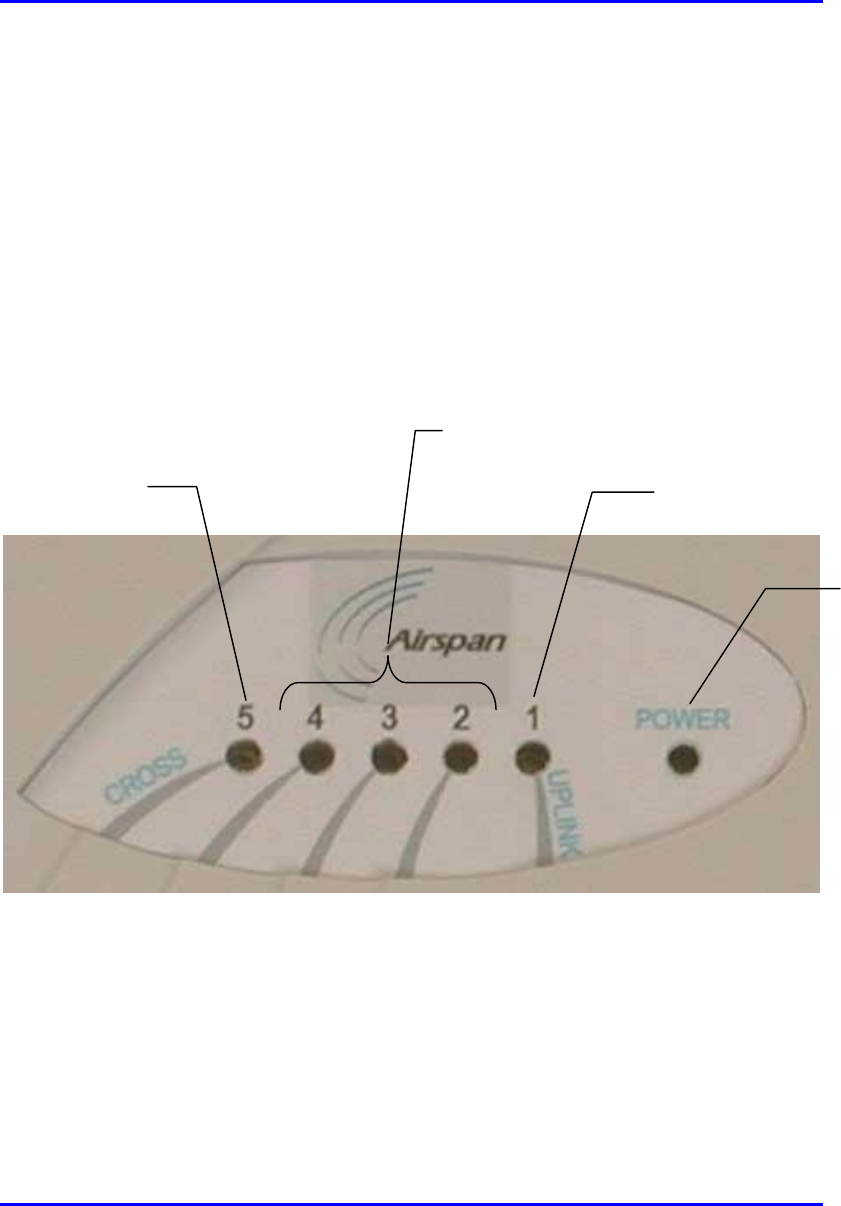
Figure 9-17 displays the location of the SDA-4H LED indicators.
Figure 9-17: SDA-4H LED indicators
UPLINK (1) LED
Ethernet LEDs (2, 3, and 4)
(
strai
g
ht-throu
g
h
)
CROSS (5) LED
POWER
LED
Installing the SDA Hardware Installation Guide
9-24 Airspan Networks Ltd. 02030311-05
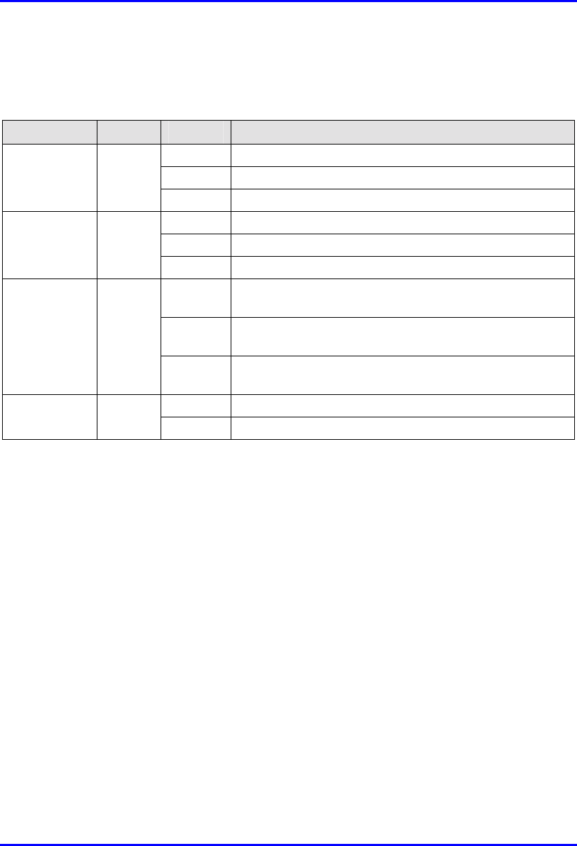
Table 9-4 describes the SDA-4H LED indicators.
Table 9-4: Description of the SDA-4H LED Indicators
LED Color Status Meaning
On Physical link between SDA-4H and SPR
Blinking Traffic flow between SDA-4H and SPR
1 (UPLINK) Yellow
Off No link between SDA-4H and SPR
On Physical link between SDA-4H and Ethernet network
Blinking Traffic flow between SDA-4H and Ethernet network
2, 3, and 4 Yellow
Off No link between SDA-4H and Ethernet network
On Physical link between SDA-4H and crossover Ethernet
port connection
Blinking Traffic flow between SDA-4H and crossover Ethernet
port network
5 (CROSS) Yellow
Off No link between SDA-4H and crossover Ethernet port
connection
On Power received by the SDA-4H.
POWER Green
Off No power received by SDA-4H
Hardware Installation Guide Installing the SDA
02030311-05 Airspan Networks Ltd. 9-25
9.7.2. SDA-4S Models
Table 9-5 describes the SDA-4S model’s LED indicators.
Table 9-5: Description of the SDA-4S model’s LED indicators
LED Color Status Meaning
On Physical link (10BaseT) between SDA-4S and SPR
Blinking Traffic flow between SDA-4S and SPR
1 Orange
Off No link between SDA-4S and SPR
On 100BaseT physical link between SDA-4H and Ethernet
network
Blinking 100BaseT traffic flow between SDA-4H and Ethernet
network
Green
Off No traffic flow between SDA-4S and Ethernet network
On 10BaseT physical link between SDA-4H and Ethernet
network
Blinking 10BaseT traffic flow between SDA-4H and Ethernet
network
2, 3, 4, and 5
Orange
Off No traffic flow between SDA-4S and Ethernet network
On Power received by the SDA-4S model.
POWER Green
Off No power received by SDA-4S model.

02030311-05 Airspan Networks Ltd. 10-1
Installing the IDR
Installing the IDRInstalling the IDR
Installing the IDR
This chapter describes the installation of the WipLL Indoor Data Radio (IDR),
which is installed at the base station.
This chapter includes the following sections:
! Overview
! Physical Dimensions and Basic Design
! Mounting the IDR
! Desk Mounting
! Wall and Pole Mounting
! Connecting a Third-Party External Antenna
! Connecting to an Ethernet Network
! Positioning IDR for Optimum RF Reception
! Connecting to PC for Serial Configuration
! Connecting Power
! Power LEDs
10
Installing the IDR Hardware Installation Guide
10-2 Airspan Networks Ltd. 02030311-05
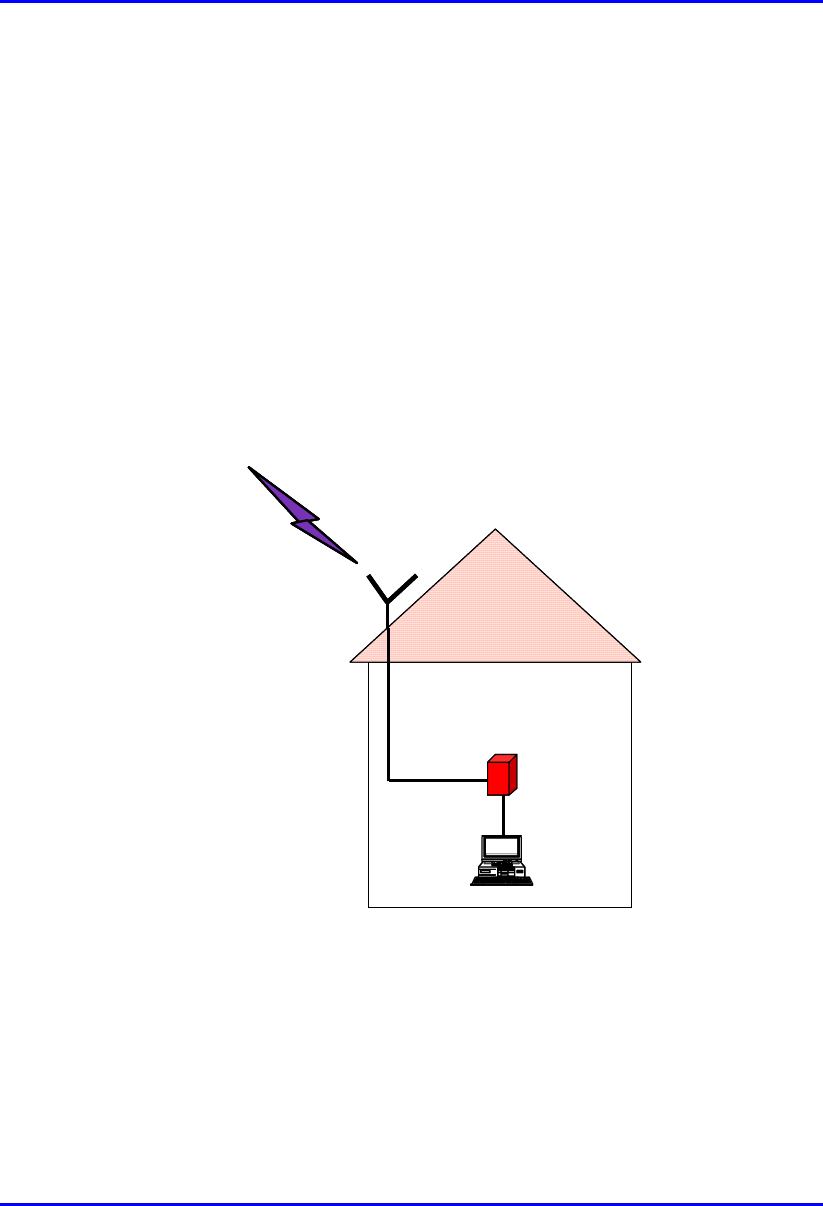
10.1. Overview
The IDR device is an optional WipLL device that combines the functionality of the
SPR and SDA devices. The IDR has a built-in antenna that provides an interface for
transmission with the base station. In addition, the IDR provides an interface for
10Base-T Ethernet with the subscriber's network. However, unlike the SDA, a
separate power supply unit (power adapter) powers the IDR.
The IDR is available in two models:
! IDR with an internal antenna
! IDR with a TNC connector for connecting to a third-party external antenna
RF link
t
o BSR
Optional external
Optional externalOptional external
Optional external
antenna
antennaantenna
antenna
RF cable
IDR
PC
RF link
t
o BSR
Optional external
Optional externalOptional external
Optional external
antenna
antennaantenna
antenna
RF cable
IDR
PC
Figure 10-1: Typical IDR setup at subscriber's premises (showing optional antenna)

Hardware Installation Guide Installing the IDR
02030311-05 Airspan Networks Ltd. 10-3
Warning: To avoid electrical or fire hazard, ensure that all connections to the
IDR are performed prior to connecting the power supply.
Note: The digital portion of the transceiver has been tested and found to
comply with the limits for a Class B digital device, pursuant to part 15 of the
FCC rules. These limits are designed to provide reasonable protection against
harmful interference in a residential installation. This equipment generates,
uses, and can radiate radio frequency energy and, if not installed and used in
accordance with the instructions, may cause harmful interference to radio
communications. However, there is no guarantee that interference will not
occur in a particular installation. If this equipment does cause harmful
interference to radio or television reception, which can be determined by
turning the equipment on and off, the user is encouraged to try correct the
interference by performing one or more of the following measures:
- Reorientate or relocate the receiving antenna
- Increase separation between the equipment and receiver
- Connect the equipment to an outlet on a circuit different from that to which
the receiver is connected
- Consult the dealer or an experienced radio/TV technician for help
Installing the IDR Hardware Installation Guide
10-4 Airspan Networks Ltd. 02030311-05
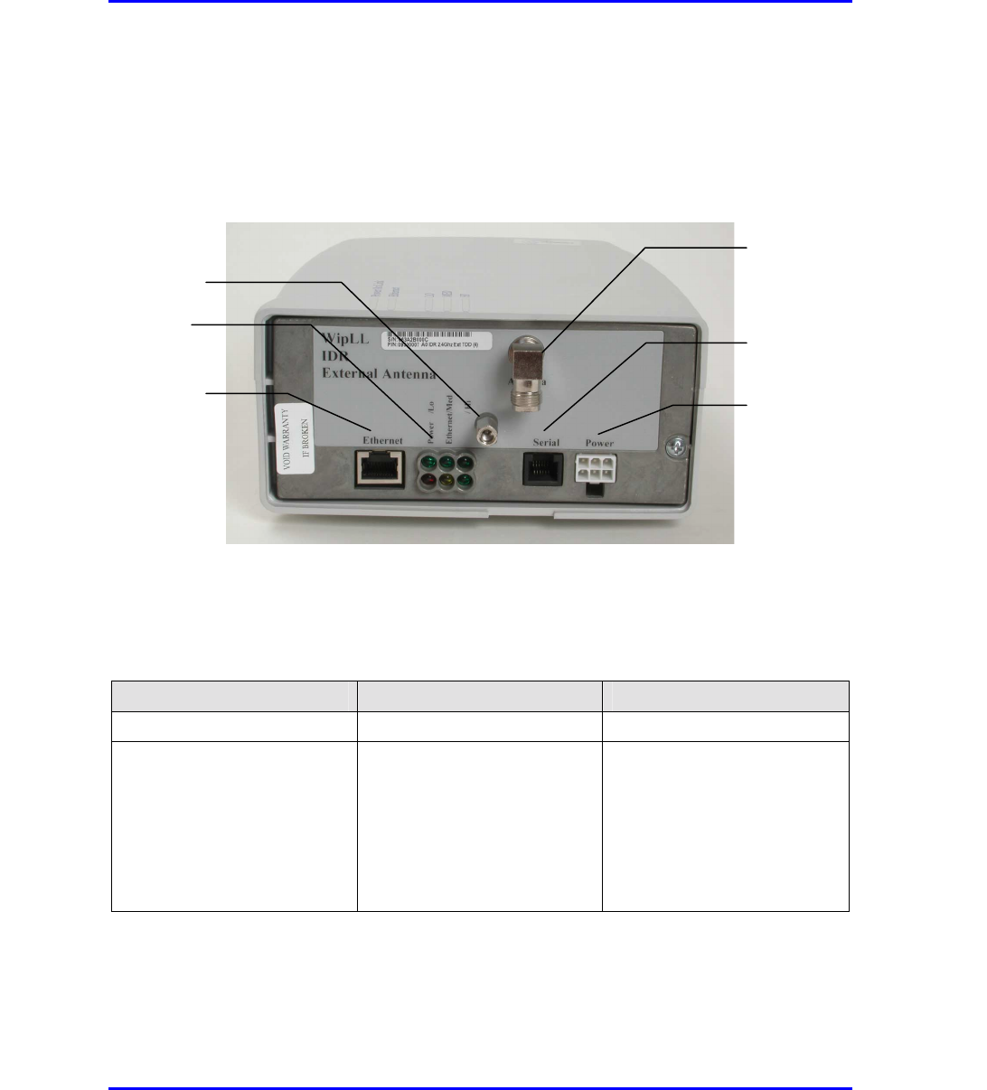
10.2. Physical Dimensions and Basic Design
The IDR is encased in a chassis providing access to the IDR's communication port at
the front panel.
Figure 10-2: IDR front panel with cover removed exposing ports
The IDR's physical dimensions are described in Table 10-1.
Table 10-1: IDR physical dimensions
Parameter Value Comment
Weight 1,43 kg
Dimensions (H x W x D)
• IDR with built-in antenna
• IDR with an external
antenna
• 155 mm (6.1 inches) x 233
mm (9.17 inches) x 74.5
mm (2.93 inches)
• 120.5 mm (4.74 inches) x
61mm (2.4 inches) x 35
mm (1.37 inches)
Note: Dimensions exclude the
external power adapter.
TNC-type connector for
3rd party external antenna
RJ-11 serial port
Molex 6-pin power port
LEDs
RJ-45 10Base-T port
Chassis cover bolt
Hardware Installation Guide Installing the IDR
02030311-05 Airspan Networks Ltd. 10-5
10.3. Mounting the IDR
The IDR may be mounted in the following ways:
! Desk
! Pole
! Wall
Note: Before mounting or attaching any brackets to the IDR, ensure that all
cables are securely attached and that the unit functions correctly in the
proposed location.
10.3.1. Desk Mounting
The IDR may be mounted on a desk in one of the following ways:
! Vertically
! Horizontally
Installing the IDR Hardware Installation Guide
10-6 Airspan Networks Ltd. 02030311-05
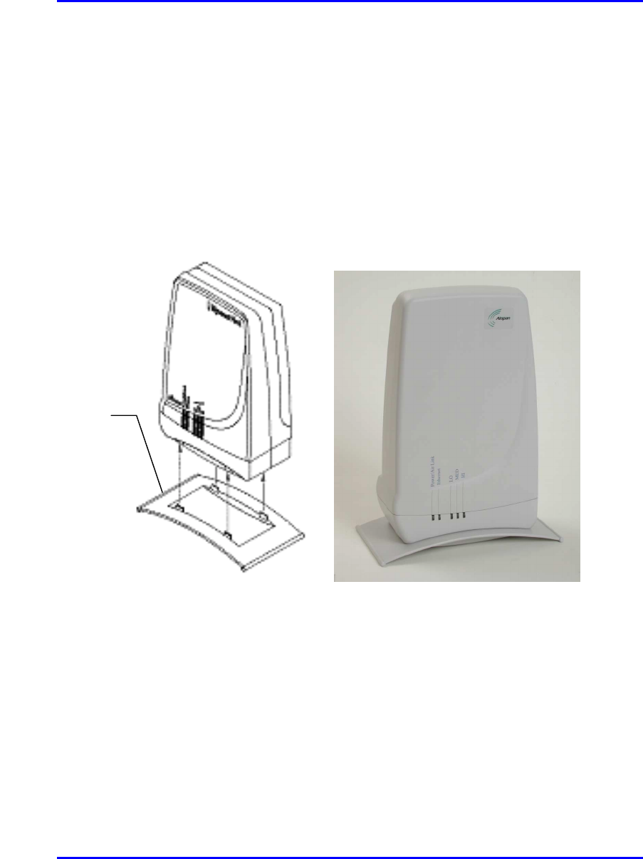
10.3.1.1. Vertical-Desk Mounting
A base plate is provided to mount the unit vertically on the desk, i.e., in standing
position. The base plate is designed to fit in one position only.
To desk mount the IDR in a vertical position:
! Insert the IDR into the base and press firmly until the tabs click into place. See
Figure 10-3.
Figure 10-3: IDR vertical desk mounting
Desk-
mounting
p
late
Hardware Installation Guide Installing the IDR
02030311-05 Airspan Networks Ltd. 10-7
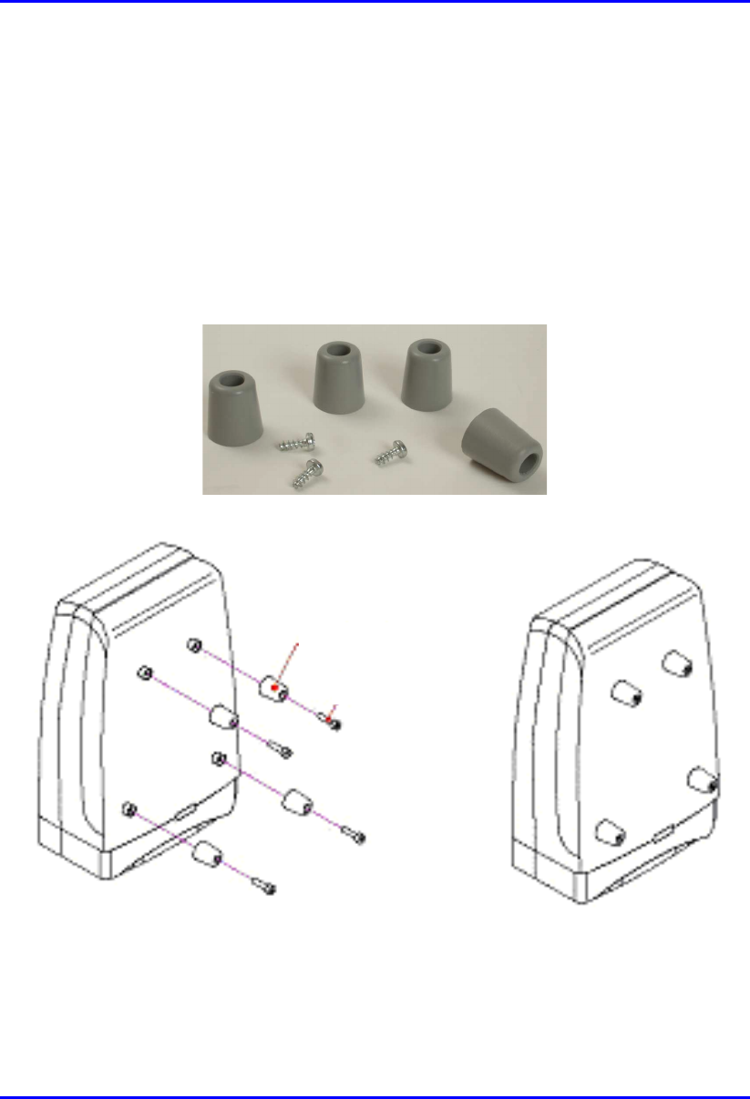
10.3.1.2. Horizontal-Desk Mounting
To position the IDR horizontally on the desk, four rubber pads, supplied with the
unit, must be fitted to avoid damage to mounting surfaces.
mTo desk mount the IDR in a horizontal position:
! Secure the rubber pads to the posts provided on the rear of the IDR using four
self-tapping screws. See Figure 10-4.
Figure 10-4: IDR horizontal desk mounting using supplied rubber pads and tapping
screws
Rubber foot
Screw
Installing the IDR Hardware Installation Guide
10-8 Airspan Networks Ltd. 02030311-05
10.3.2. Wall and Pole Mounting
The IDR may be mounted to a wall or to a 5-cm diameter pole. Wall and pole
mounting both use the same mounting brackets and wall hanger plate.
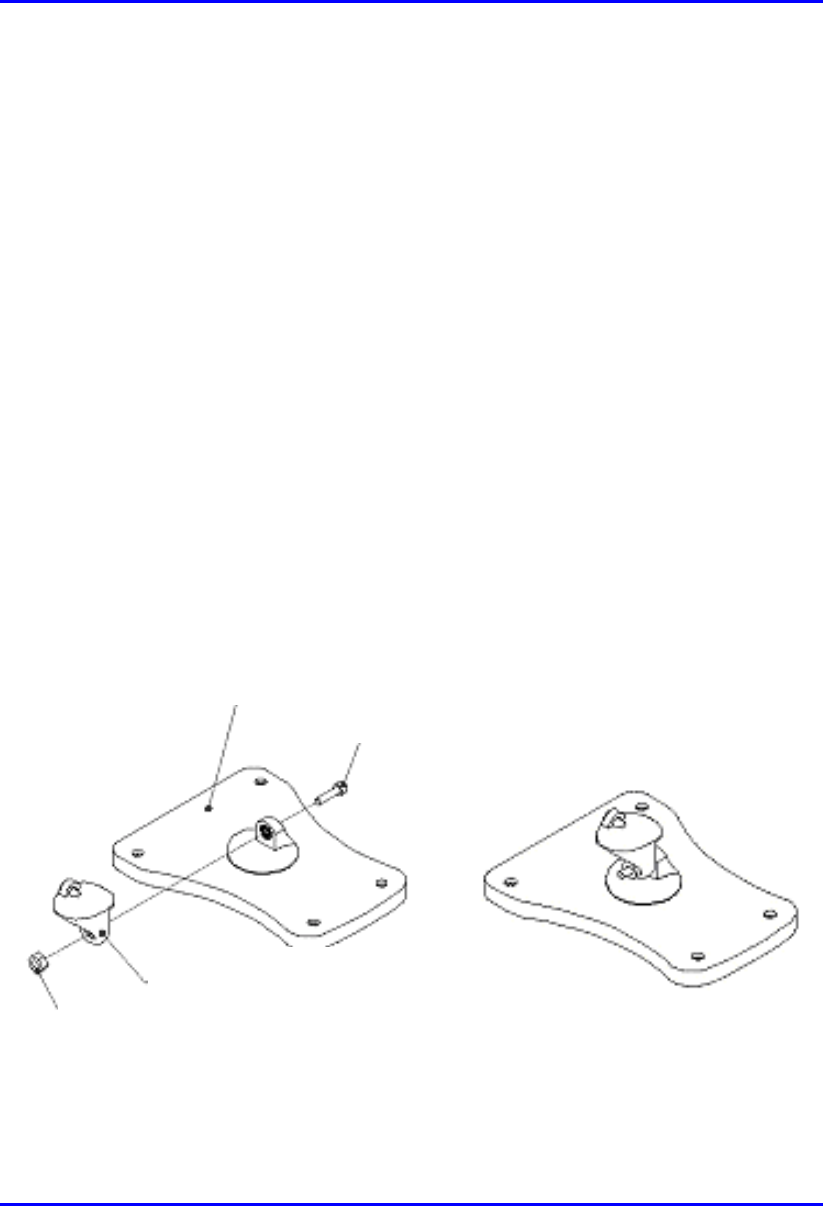
10.3.2.1. Assembling the Bracket and Hanger Plate
The wall hanger plate secures the IDR to a wall or pole. The wall bracket and hanger
plate allows positioning the IDR in the correct orientation. Holes are provided in the
wall hanger plate for both pole and wall mounting options
To assemble the bracket and hanger plate:
1. Insert a 4 mm hex nut into the slot on the tilt arm component
2. Holding the nut in place, attach the tilt arm to the mounting bracket using a 4
mm socket head bolt. Hand tighten the bolt only. See Figure 10-5.
3. Affix the complete mounting assembly to the rear of the IDR using the 4-off
self-tapping screws supplied with the kit.
Figure 10-5: Mounting bracket assembly
Mounting Bracket
Screw
Tilt Arm
N
ut
Hardware Installation Guide Installing the IDR
02030311-05 Airspan Networks Ltd. 10-9
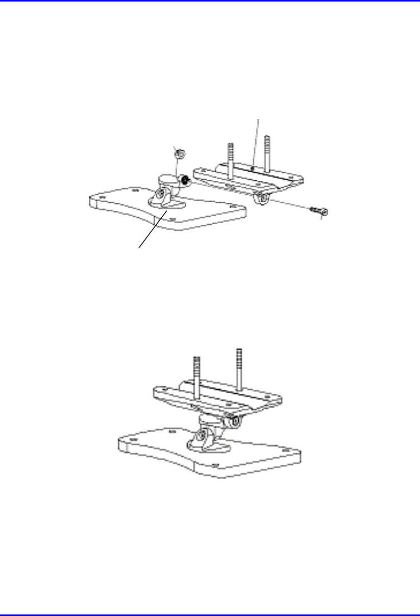
4. Attach the wall bracket assembly to wall hanger using an M4 socket-head bolt
and nut as shown in Figure 10-6. The bolt is only to be hand tightened at this
stage.
Wall Hanger
M-4 nut
Screw
Mounting bracket
assembly
Figure 10-6: Wall hanger fixing method
Figure 10-7: Wall hanger & mounting bracket assembly
Installing the IDR Hardware Installation Guide
10-10 Airspan Networks Ltd. 02030311-05
5. Once assembled, the IDR mounting bracket assembly may be secured to the rear
of the IDR using the 4-off self-tapping screws supplied in the unit fixing kit. See
Figure 10-8.
Figure 10-8: Mounting bracket assembly secured to IDR
Self -
tapping
Screws
Hardware Installation Guide Installing the IDR
02030311-05 Airspan Networks Ltd. 10-11
10.3.2.2. Pole Mounting
Prior to mounting the IDR to a pole the wall mounting bracket assembly must be
fitted as described in the previous section.
To pole mount the IDR:
1. Offer up the IDR assembly to the pole as shown in Figure 10-9.
2. Insert 2-off M10 bolts through the holes in the wall hanger.
3. Slide the clamp-holder into position and secure using washers, spring-washers
and nuts as illustrated in Figure 10-10. Finger-tighten the fasteners.
4. Slide the IDR to the required location on the pole and fully tighten the fasteners.
Figure 10-9: IDR pole mounting components
Clam
p
holde
r
Washe
r
Spring
Washe
r
Hex Nut
Bol
t
Installing the IDR Hardware Installation Guide
10-12 Airspan Networks Ltd. 02030311-05
Figure 10-10: IDR secured to a pole
To set the correct IDR inclination:
1. Loosen the 2-off M4 socket head screws on the mounting bracket tilt-arm
2. Position the IDR at the desired angle.
3. Re-tighten the 2 off socket screws on the tilt arm.

Hardware Installation Guide Installing the IDR
02030311-05 Airspan Networks Ltd. 10-13
10.3.2.3. Wall Mounting
Warning: Prior to drilling holes in a wall ensure that there are no hidden
services such as electricity cables or water pipes. A stop must be used on the
power drill to ensure that bored holes do not exceed 35 mm.
To mount the IDR on a wall:
1. Loosen the 2-off M4 socket head screws on the mounting bracket tilt-arm and
remove the wall hanger.
2. Offer up the wall hanger to the wall and scribe through the mounting hole
locations.
3. Drill holes to suit the type of wall fixing.
4. If required insert anchor plugs suited to the wall material.
5. Affix the wall hanger using 4-off screws suited to the anchor plugs and wall
material.
6. Re-attach the IDR mounting bracket to the wall hanger. Finger tighten the
screws.
7. Position the IDR at the desired inclination.
8. Re-tighten the screws to lock the IDR in position.
Installing the IDR Hardware Installation Guide
10-14 Airspan Networks Ltd. 02030311-05
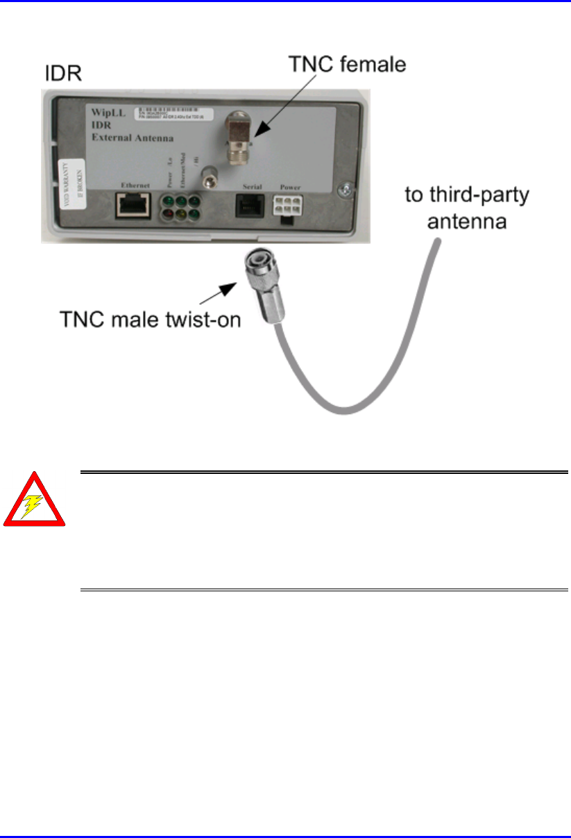
10.4. Connecting a Third-Party External
Antenna
The IDR provides a TNC-type connector for connecting a third-party antenna to the
IDR. This antenna can be placed on the subscriber’s windowsill to provide better RF
signal reception with the BSR.
Note: Airspan supplies unterminated cables for N-type connectors. Therefore,
refer to the cable crimping procedures for N-type connectors detailed in
Appendix B, “Cable Crimping".
! Connector: TNC-type male
Warning: Before connecting the external antenna, ensure that the IDR is NOT
connected to the power source.
Hardware Installation Guide Installing the IDR
02030311-05 Airspan Networks Ltd. 10-15
Figure 10-11: Connecting a third-party antenna
Warning: It is the responsibility of the person installing the WipLL system
to ensure that when using the outdoor antenna kits in the United States (o
r
where FCC rules apply), that only those antennas certified with the product are
used. The use of any antenna other than those certified with the product is
expressly forbidden in accordance with FCC rules CFR47 part 15.204. The
installer should configure the output power level of antennas according to
country regulations and per antenna type.
Installing the IDR Hardware Installation Guide
10-16 Airspan Networks Ltd. 02030311-05
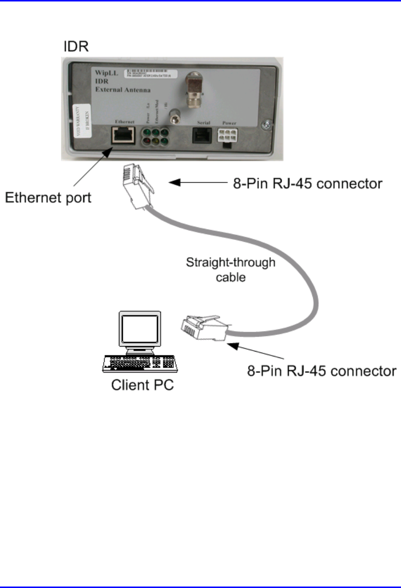
10.5. Connecting to an Ethernet Network
The IDR provides one Ethernet interface for the subscriber’s Ethernet network. This
port is located on the front panel, and labeled Ethernet.
! Connector: 8-Pin RJ-45
! Cable: CAT-5
! Connector pinouts:
Pin Function
1 Rx+
2 Rx-
3 Tx+
4
N
ot Connected
5
N
ot Connected
6 Tx-
7
N
ot connected
8
N
ot connected
To connect IDR to the subscriber’s Ethernet network:
1. Attach the 8-pin RJ-45 connector, at one end of the cable, to the IDR's Ethernet
port, labeled Ethernet (see Figure 10-12).
2. Attach the 8-pin RJ-45 connector, at the other end of the cable, to the PC's LAN
port (see Figure 10-12).
Hardware Installation Guide Installing the IDR
02030311-05 Airspan Networks Ltd. 10-17
Figure 10-12: Connecting IDR to a client PC
Installing the IDR Hardware Installation Guide
10-18 Airspan Networks Ltd. 02030311-05
10.5.1. Ethernet LED Indicator
The IDR provides one LED that indicates an Ethernet connection. This LED is
labeled Ethernet and is located on the IDR’s top panel.
Table 10-2: Description of Ethernet LEDs
LED Color Status Indicates
On Physical link between IDR and Ethernet network
Off No physical link between IDR and Ethernet network
Ethernet Orange
Blinking Data is flowing through the Ethernet port
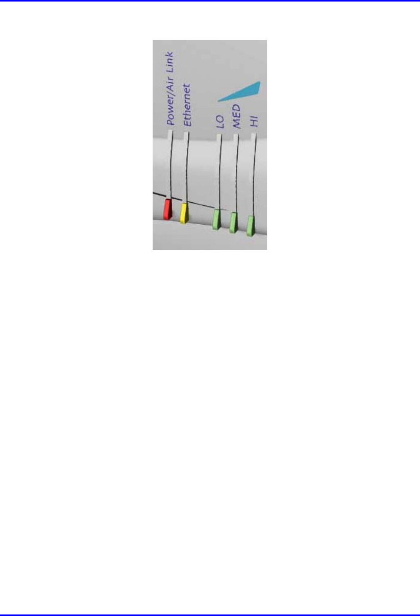
10.6. Positioning IDR for Optimum RF
Reception
Once mounted to a wall, pole, or desk the IDR unit may be positioned to ensure the
best RF signal communication with the BSR. The RF signal strength is indicated by
three LEDs on the IDR chassis. The following table describes the RF signaling
strength indicator LEDs.
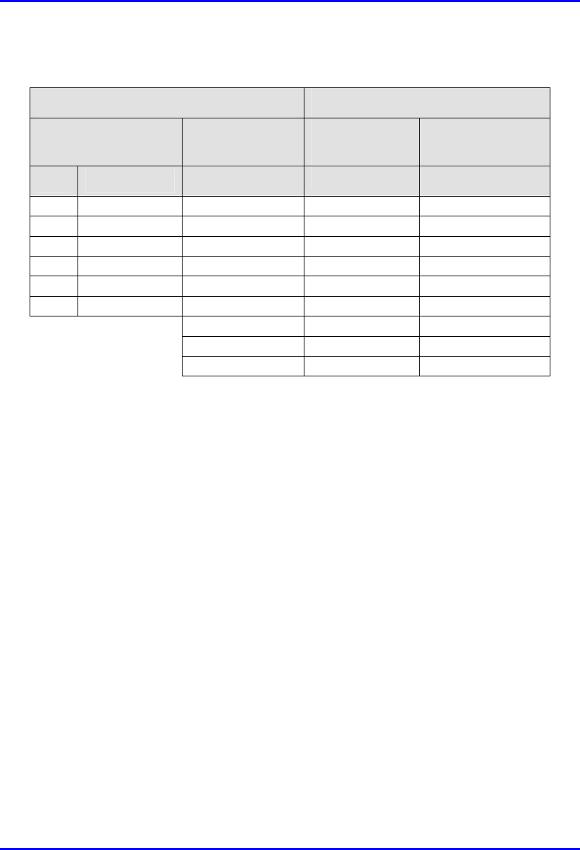
Table 10-3: Description of RF signal strength LEDs
Description LED Color Function Status
Previous
Releases
Release 4.2B
All LEDs On RSSI ≥ -60 dBm RSSI ≥ -60 dBm
Two LEDs On -65 dBm ≤ RSSI ≤
-61 dBm
-70 dBm ≤ RSSI <
-60 dBm
One LED On -70 dBm ≤ RSSI ≤
-66 dBm
-80 dBm ≤ RSSI <
-70 dBm
One LED
Blinking
RSSI ≤ -77 dBm -90 dBm ≤ RSSI <
-80 dBm
RSSI
LEDs:
LO,
MED,
and HI
Green RSSI level
All LEDs Off -76 dBm ≤ RSSI ≤
-71 dBm
RSSI < -90 dBm
Hardware Installation Guide Installing the IDR
02030311-05 Airspan Networks Ltd. 10-19
Figure 10-13: IDR LED indicators
To position the IDR for optimum RF signal:
! Position the IDR until all three RF signaling strength indicator LEDs are lit.
Refer to Section 10.3.2, “Wall and Pole Mounting” page 10-8 for details on
adjusting IDR wall and pole mounting position.
For desk-top mounting, the IDR can be simply relocated to obtain the strongest
signal.

Installing the IDR Hardware Installation Guide
10-20 Airspan Networks Ltd. 02030311-05
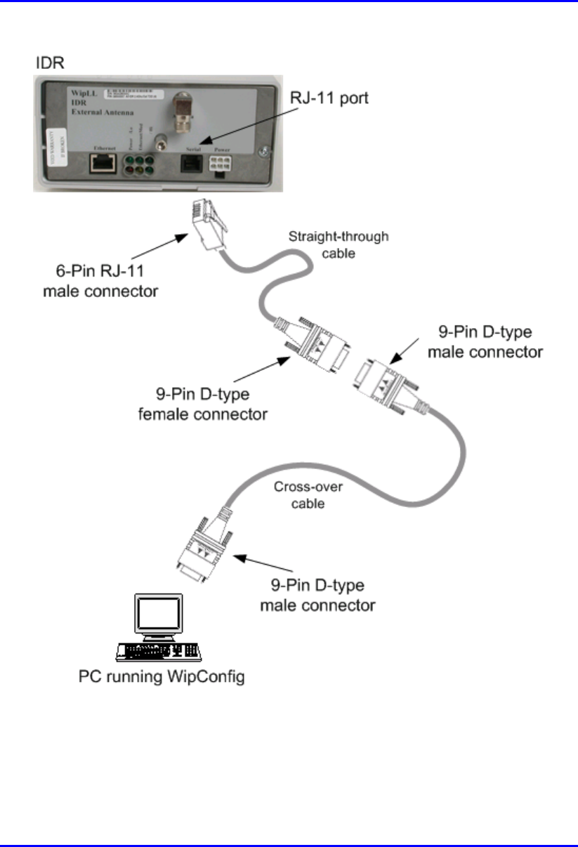
10.7. Connecting to PC for Serial Configuration
To perform IDR initial configuration, you need to connect the IDR’s RJ-11 port to
the serial port of a PC running the WipLL network management application (i.e.,
WipConfig).
The IDR’s RJ-11 port labeled Serial, located on the front panel, connects to the
serial port of a PC via a cable with an RJ-11 connector on the one end, and a 9-Pin
D-type connector on the other (i.e., a direct serial cable connection-DCC).
! Connectors:
! 6-Pin RJ-11 male to 9-pin D-type female adapter
! 9-Pin D-type male to 9-Pin D-type female adapter
! Cable:
! Straight-through cable with 6-Pin RJ-11 male on one end and 9-Pin D-type
female on the other (connects between IDR and crossover cable)
! Crossover cable with 9-Pin D-type male on one end and 9-Pin D-type
female on the other (connects straight-through cable to PC)
Hardware Installation Guide Installing the IDR
02030311-05 Airspan Networks Ltd. 10-21
! Connector pinouts:
Straight-through cable Crossover cable
6-Pin RJ-11 9-Pin D-type
female
9-Pin D-type
male
9-Pin D-type
male
Pin Function Pin Pin Pin
1 Rx 2 4 3
2
N
ot connected - - -
3
N
C - - -
4
N
C - - -
5 GND 5 1 5
6 Tx 3 3 2
- - -
- - -
- - -
To connect the IDR to the WipLL management station (PC):
1. Connect the 6-Pin RJ-11 connector to the IDR’s RJ-11 port (labeled Serial)
located on the IDR’s front panel (see Figure 10-14).
2. Connect the 9-Pin D-type female connector, at the other end of the straight-
through cable, to the 9-Pin D-type male connector of the cross-over cable (see
Figure 10-14).
3. Connect the 9-Pin D-type male connector, at the other end of the cross-over
cable, to the PC’s serial port (see Figure 10-14).
Installing the IDR Hardware Installation Guide
10-22 Airspan Networks Ltd. 02030311-05
Figure 10-14: IDR-to-PC Serial Cable Connections
Hardware Installation Guide Installing the IDR
02030311-05 Airspan Networks Ltd. 10-23
10.8. Connecting Power
The IDR is powered by an external power supply (Triple Output External Adapter).
The IDR connects to the power adapter via the IDR's power port located on the
IDR’s front panel.
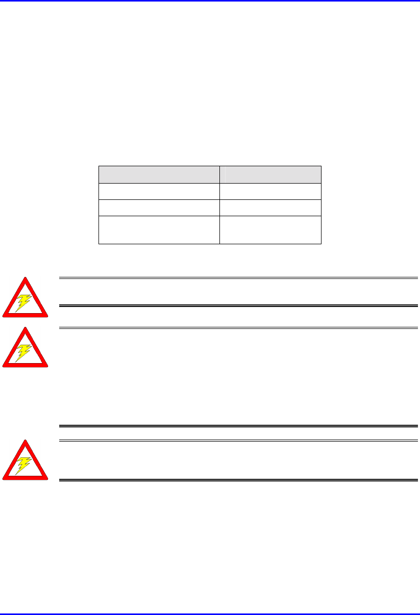
The following table lists the external power supply specifications:
Table 10-4: IDR power supply requirements
Power parameter Units
Voltages 110-240 VAC
Frequency 50 to 60Hz
Maximum power
consumption
Less than 15W
Warning: If you are using an external antenna, ensure that you connect the
antenna before connecting the BSR to the power source.
Warning: Ensure that plugs fitted to mains power leads for subscriber
premises equipment are compatible with AC mains sockets. Do not replace
plugs on power leads to suit local requirements without first verifying earthing
practice for the country and equipment in question.
Careful consideration must be given to issues including local wiring
requirements, cable color-coding, and safety earthing and circuit protection
requirements.
Warning: To avoid electrical or fire hazard, ensure that the data connections
to the IDR are made prior to connecting the power supply.The AC mains must
be capable of supplying at least 230 VAC
Prior to connecting to the power outlet, the following pre-connection inspection
should be performed on power sockets:
! Power socket shall be visually inspected to ensure that no other equipment is
connected to the power outlet.
Installing the IDR Hardware Installation Guide
10-24 Airspan Networks Ltd. 02030311-05
! There is no physical sign of damage to the power outlet.
! There should not be any visible sign of water or dampness on or around the
power outlet.
! The plug and socket assemblies are to be firmly secured.
! The power outlet shall be checked using a proprietary plug tester such as a
‘Martindale Ze’ type. Checks are required to verify the earth loop impedance
value and the presence of phase, neutral and earth connections.
! Connector: 6-Pin power connector
! Cable: 3-core 0.7mm² type
! Connector pinouts:
Pin Function
1 +6.5V
2 +5V
3 3.3V
4 GND
5 Not connected
6 Not connected
To connect the power:
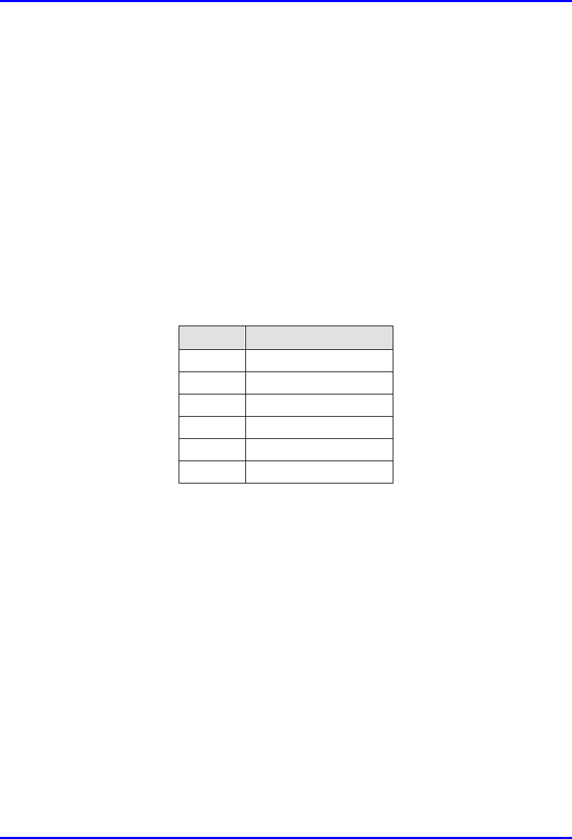
1. Plug the AC power adapter’s 6-pin Molex connector into the IDR’s power port
labeled Power (see Figure 10-15).
2. Plug the AC power plug female, at the one end of the AC power cable, into the
AC power adapter’s socket (see Figure 10-15).
3. Plug the AC power plug male, at the other end of the AC power cable, into the
electrical outlet (see Figure 10-15).
Hardware Installation Guide Installing the IDR
02030311-05 Airspan Networks Ltd. 10-25
Figure 10-15: Connecting power to the IDR
Installing the IDR Hardware Installation Guide
10-26 Airspan Networks Ltd. 02030311-05
10.8.1. Power LEDs
The IDA provides a power LED indicator, labeled Power, which indicates whether a
power supply exists. The Power LED is located on the front panel of the IDR
chassis.
Table 10-5: Description of Power LEDs
LED Color Status Meaning
On The SDA receives power supply
Power Red
Off No power received

02030311-05 Airspan Networks Ltd. A-1
Glossary
GlossaryGlossary
Glossary
AC Alternating Current
BNC Bayonet Neill Concelman (Connector type)
BSDU Base Station Distribution Unit
BSPS Base Station Power System
BSR Base Station Radio
CEP Common Earth Point
DC Direct Current
DCC Direct Serial Cable Connection
GPS Global Positioning Satellite
HSP Hop Synchronisation Process
HSPP Hop Synchronisation Process Pulse
IDR Indoor Data Radio
IP Internet Protocol
LED Light Emitting Diode
mA Milliamperes
MCB Miniature Circuit Breaker
Mbps Mega Bits Per Second
Nm Newton-metres
NMS Network Management System
NOC Network Operations Centre
PSTN Public Switched Telephone Network
RJ Registered Jack (modular connector)
A

Glossary Hardware Installation Guide
A-2 Airspan Networks Ltd. 02030311-05
SDA Subscriber Data Adaptor
SME Small and Medium Enterprises
SOHO Small Office/Home Office
SPR Subscriber Premises Radio
UPS Un-interrupted Power Supply
UPVC Unplasticized Poly-Vinyl Chloride
WAN Wide Area Network
WipLL Wireless internet protocol -Local Loop

02030311-05 Airspan Networks Ltd. B-1
Cable Crimping
Cable CrimpingCable Crimping
Cable Crimping
This chapter describes the procedure for crimping cables for 15-Pin D-type and N-
type connectors that are used in BSR/SPR-to-BSDU/SDA and BSR-to-GPS
connections, respectively. The opposite ends of these cables are un-terminated,
thereby providing length flexibility for connecting these WipLL units.
Crimping procedures are described for the following cable-connector terminations:
! CAT-5e/15-Pin D-type cable/connector terminations for SPR-to-SDA
connections
! Multipair Overall Shielded (22 AWG)/N-type cable/connector terminations
for GPS antenna connections.
! GPS antenna connector
Warning: Correct crimping of network cables is crucial for ensuring service
integrity.
B
Cable Crimping Hardware Installation Guide
B-2 Airspan Networks Ltd. 02030311-05
B.1. Crimping CAT-5e Cable for 15-Pin D-Type
Connectors
This section describes the cable stripping and crimping of CAT-5e cables for 15-Pin
D-type connectors used for BSR/SPR-to-BSDU/SDA connections.
Airspan recommends the "ITT Canon DB15" (code number ‘DAW15P’) sub-
miniature type. This connector is an Insulation Displacement Connector (IDC)
which crimps and secures the cable at the connection point.
Airspan recommends the following tools for stripping and crimping for 15-Pin D-
type connectors:
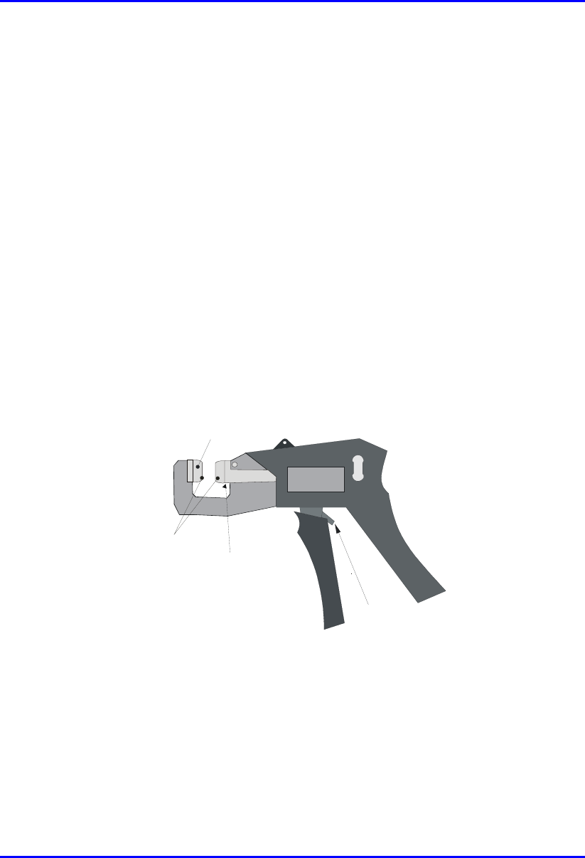
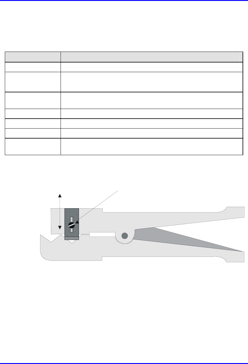
! Crimping tool—hand-crimper code DW115394-1. The crimper is a cyclic
crimper and will not release the cable until a full termination cycle has been
completed. The tool automatically indexes to the next pin on completion of the
terminating cycle.(See Figure B-1.)
Push in this direction to
release ratchet mechanism
Feed Slide
Connector Guide
Anti Backup
locator
Figure B-1: Hand-Crimping Tool for 15-Pin D-Type Connector
Hardware Installation Guide Cable Crimping
02030311-05 Airspan Networks Ltd. B-3
The major features of the crimper are described in the following table:
Table B-1: Main features of crimping tool
Tool feature Function
Terminating Head Guides and supports the connector.
Wire Inserter
• Cuts wire to be terminated.
• Forces conductors into 2 slotted beams of the contact.
Anti-backup locator Prevents connector from moving out of position for accurate
termination.
Feed Slide Automatically advances the connector after each termination.
Adjuster Provides wire insertion depth adjustment
Cam handle Activates the termination mechanism inside the head.
Ratchet Pawl Releases the cam handle before it is fully closed should a problem occur
during termination operation.
! Stripping tool—three-way stripping tool—1PAC10349AKM (see Figure B-2)
Adjustment Screw
Blade Adjustmen
t
Figure B-2: Stripping Tool 1PAC10349 AKM
Cable crimping is performed in two stages:
1. Stripping the cable
2. Crimping the cable

Cable Crimping Hardware Installation Guide
B-4 Airspan Networks Ltd. 02030311-05
B.1.1. Stripping the Cable
Before crimping the cables, you need to strip 50 mm of the cable.
Before using the tool, ensure that the tool is correctly adjusted. Correct adjustment is
obtained when the blade cuts the outer insulation without damage to the insulation of
inner conductors.
To strip the cable:
1. Cut the cable to length using cable shears (Airspan code 1PAC10333AKJ).
2. Strip 50 mm of the sheathing using stripping tool.
3. Insert the cable in the jaws of the cutting tool by squeezing the handles together.
4. Rotate 10 times, release the tool, and remove the cable and insulation.
Hardware Installation Guide Cable Crimping
02030311-05 Airspan Networks Ltd. B-5
5. Use a steel rule (1PAC10042AAV) to verify the stripped dimension.
6. Inspect the cut for evidence of damage, i.e. has the braid been cut? If so cut off
cable and reset tool.
B.1.2. Crimping the Cable
Once you have stripped 50 mm of the cable, you can begin crimping the cable to the
15-Pin D-type connector.
Note: For 15-Pin D-type connector pinouts, see the relevant chapter on the
specific WipLL equipment.
To crimp the cable:
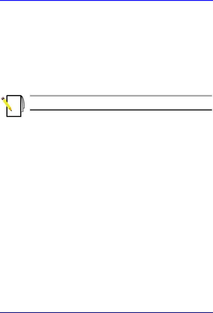
1. Insert the 15-Pin D-type connector into the left slot of the crimper until the
desired connector pin position aligns with the slot.
2. Insert the wire into the left side of the crimper slot until the end enters the hole.
3. Adjust the desired length of the wire.
4. Centre the wire in the slot.
5. Squeeze the crimper handles until the wire inserter bottoms out.
6. Release the crimper handles—the inserter retracts and the connector advances to
the next pin position.
7. Repeat the above until all pin contacts of the row have been terminated.
Cable Crimping Hardware Installation Guide
B-6 Airspan Networks Ltd. 02030311-05
Connector advances in
this direction
Wire Slot
Figure B-3: Crimping tool
8. When finished, remove the connector from the right side of connector slot.
Note: The connector must be inserted into the crimper from the left hand side
only.
Should the connector jam in the terminating position, excessive force must not
be used: the spigot between the tool handles should be used to release the
ratchet mechanism.
The crimper handle will not allow release until a full termination cycle of the
connector has been completed.
B.1.3. Inspecting the Crimped Connector
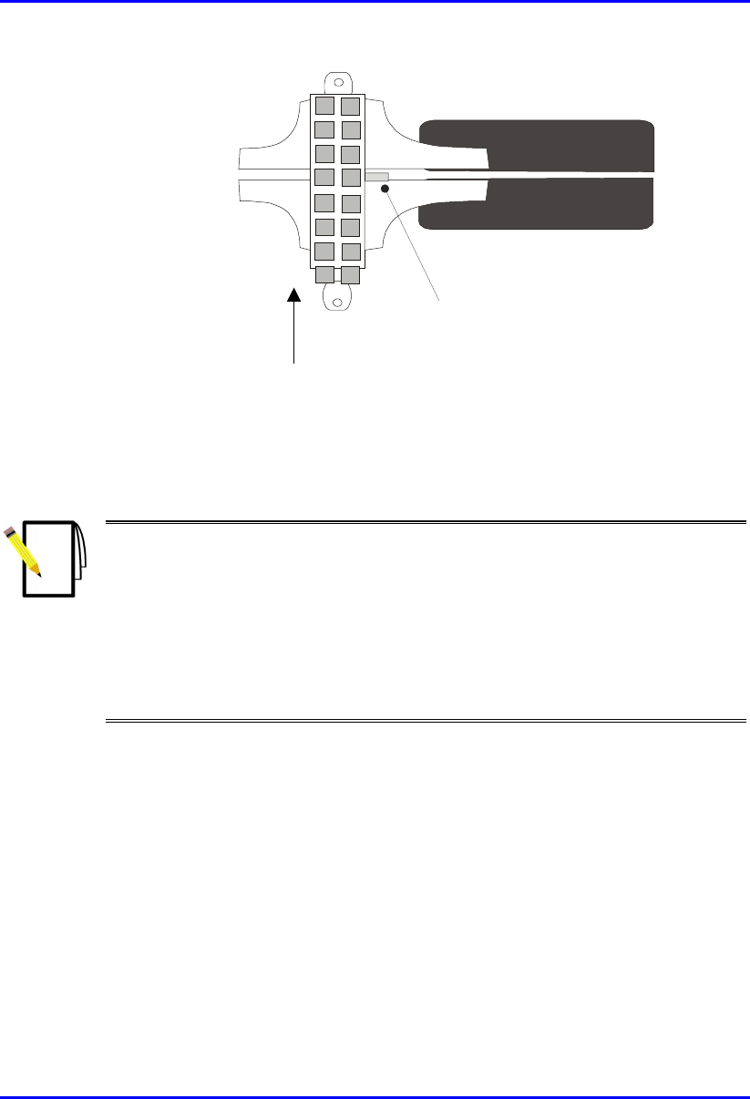
Each crimped connector is to be tested that it has been correctly crimped:
! Ensure that the wire extends beyond the front pin contact slot by a minimum of
0.5 mm
! Ensure that the two legs of the insulation crimp barrel are closed to secure the
insulation of the wire
Hardware Installation Guide Cable Crimping
02030311-05 Airspan Networks Ltd. B-7
Note: The purpose of the barrel is to prevent the wire from being lifted from
the contact. It is not necessary to have the barrel wrapped tightly around the
insulation.
! Ensure that the contact cavity has not been deformed
! Confirm integrity by holding the connector in one hand and pulling lightly on
the cable.
Figure B-4 shows points to be observed during quality inspection.
Correct Termination
Acceptable Termination
Wire was not fully inserted before termination
( or was slightly drawn back during termination)
Incorrect setting of tool
0.5mm Min
Figure B-4: Crimp Connector Inspection
Cable Crimping Hardware Installation Guide
B-8 Airspan Networks Ltd. 02030311-05
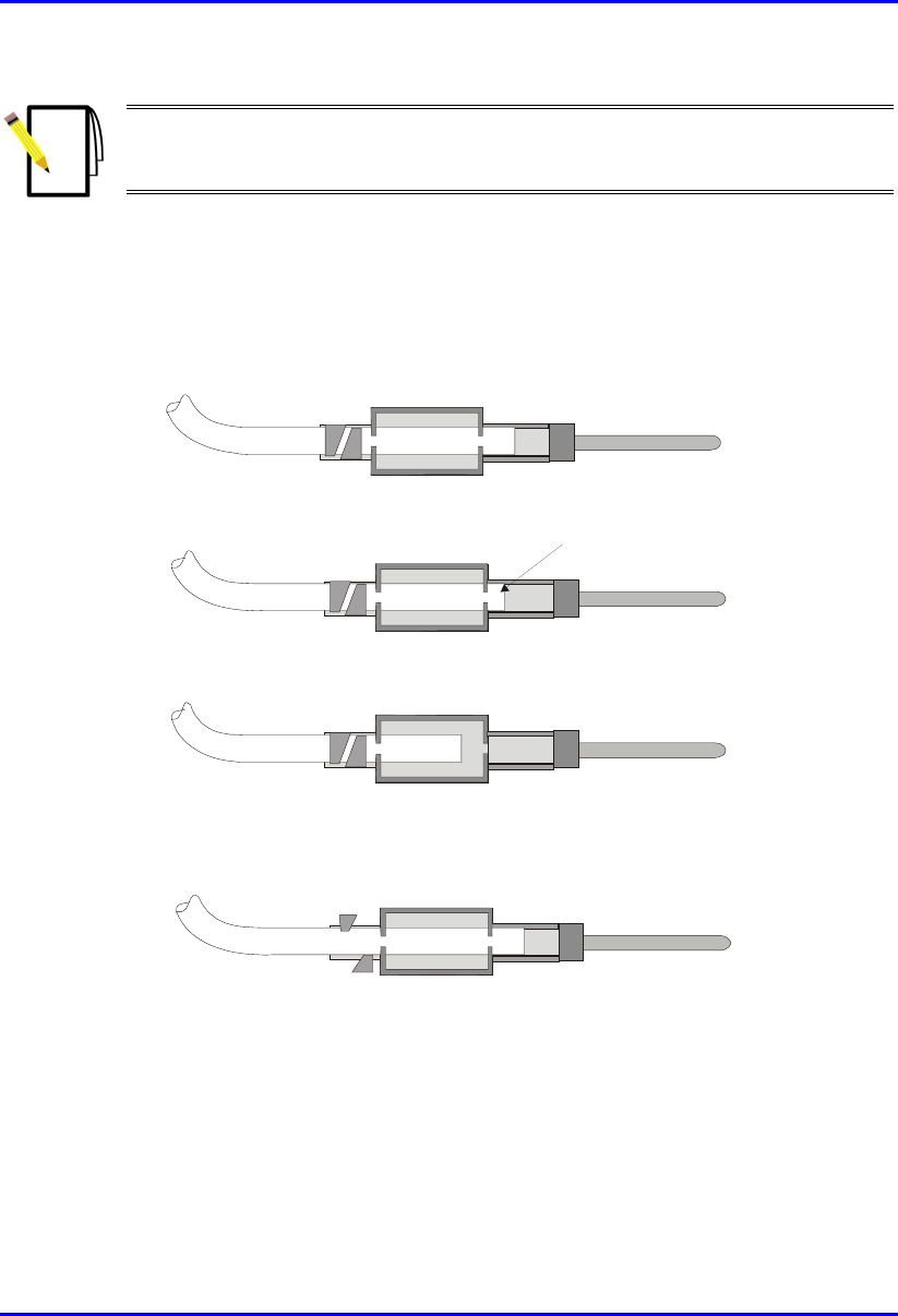
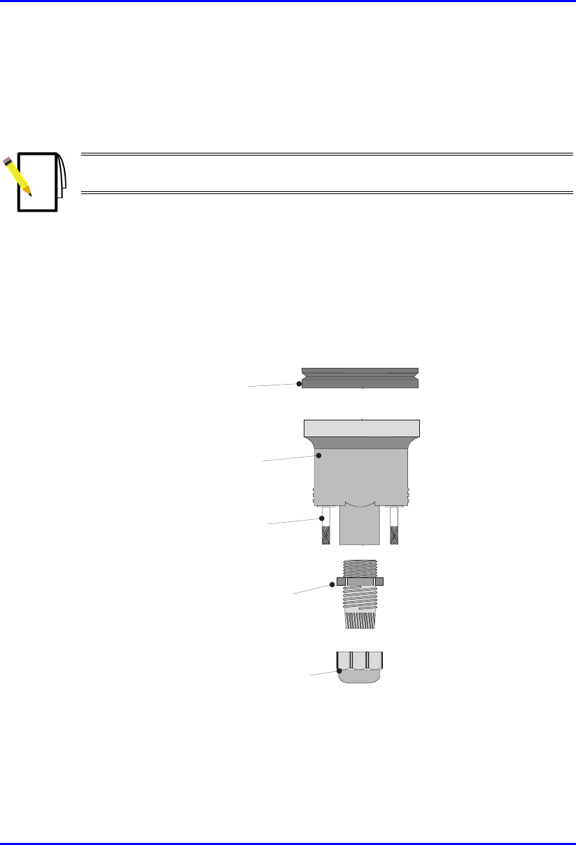
B.1.4. Housing the Connector
For outdoor cable installations, the connector is to be protected in a waterproof
housing assembly as shown in Figure B-5.
Note: The housing, cable seal, and clamping nut are to be slid onto the cable
prior to crimping the connector in place.
To assemble the connector in a waterproof housing:
1. Insert the connector into the waterproof housing ensuring that a "click" is heard.
2. Screw the cable seal into place ensuring that the cable outer sheath is inside the
connector body.
3. Secure the cable in place with the lock nut.
Cable Seal
Clamping Nut
Sealing Ring
Connector Housing
Securing Screws
Figure B-5: Waterproof Connector housing assembly
For indoor cabling applications it is not necessary to use a waterproof housing for
the connector.

Hardware Installation Guide Cable Crimping
02030311-05 Airspan Networks Ltd. B-9
To assemble the un-housed connector:
1. Insert the connector terminal block into the connector body.
2. Secure the cable onto the connector body using the cable clamp. Ensure that the
cable outer sheath is within the connector body.
3. Snap the top section of the connector body into place.
4. Ensure that the connector is secure within the housing by applying a light pull on
the cable.

Cable Crimping Hardware Installation Guide
B-10 Airspan Networks Ltd. 02030311-05
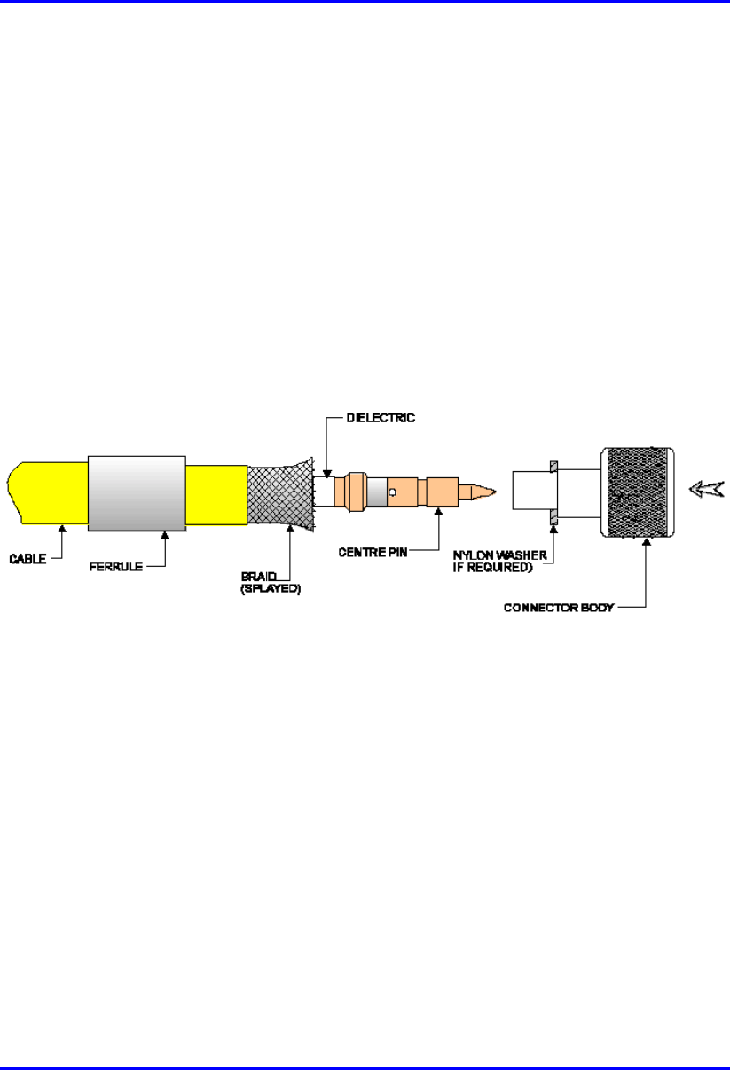
B.2. Crimping N-type Connectors
This section describes the cable stripping and crimping Multipair Overall Shielded
(22 AWG) cables for N-type connectors used for BSR/SPR connections to external
antennas.
Airspan recommends using the following tools for crimping of N-type connectors:
! Crimp tool: Erma 29020 with die set 29207.
! Stripping tool: Maxi Corex, fitted with the 9.0 to 11.5mm cable clamp (blue)
and the 9.5 to 3.2 blade cassette (green).
B.2.1. Stripping the Cable
To strip the cable:
1. The first cut should be set to cut through the outer sheath, braid and dielectric.
Scoring of the centre conductor should not occur.
2. The second cut should be set to cut through the outer sheath and the braid.
Important attention must be paid to the dielectric where it meets the braid. It is
preferable that no cutting of the dielectric takes place, however, because of the
construction of cables and tolerance build up there may be occasion where a
slight cutting of the dielectric is unavoidable. This must be kept to an absolute
minimum. This has been termed the compromise cut and is acceptable practice.
3. The final cut should be set to cut through the outer sheath only. Scoring of the
braid should not occur.
4. All sections of the stripped Ethernet cable should be easily removed if the blade
settings are correct. To adjust the blade settings use the allen key provided and
apply it to the grub screws at the back of the stripping tool. Clockwise will
increase blade depth, anti-clockwise will reduce blade depth.
5. Set stripping tool slide mechanism to 5.
6. Place the cable into the stripping tool with approximately 12 mm protruding
from the end of the tool.

Hardware Installation Guide Cable Crimping
02030311-05 Airspan Networks Ltd. B-11
7. Clamp the tool around the cable and lock in position.
8. Holding the cable in the left hand and stripping tool in the right hand (index
finger through finger hole) rotate tool in a clockwise direction for 10 turns.
9. Move slide mechanism to number 3.
10. Rotate tool in a clockwise direction for 10 turns.
11. Move slide mechanism to number 1.
12. Rotate tool in a clockwise direction for 10 turns.
13. Unlock the tool to remove cable then lock shut. Always keep the stripping tool
locked shut when not in use. Take care when handling the blade insert.
14. Twist off stripped cable sections.
Cable Crimping Hardware Installation Guide
B-12 Airspan Networks Ltd. 02030311-05
B.2.2. Assembling the Connector
Once you have stripped the cable, you can house the cable:
To house the cable:
1. Fit an insulating boot if required, over the cable, cutting enough of the pointed
end to enable the cable to go through the resulting hole with a fairly tight grip.
Push ferrule over the stripped section of cable.
2. Rotate the centre conductor in relation to the cable to splay the braid and any foil
from the dielectric, which will allow the later correct fitting of the connector
body (over the dielectric). See Figure B-6.Take care not to damage the braid.
Figure B-6: Rotating conductor
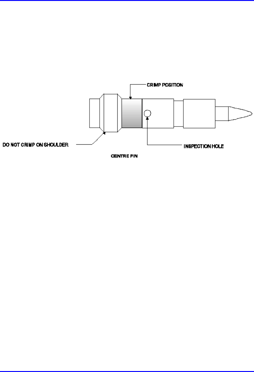
Hardware Installation Guide Cable Crimping
02030311-05 Airspan Networks Ltd. B-13
3. Trim the centre conductor back to 5.5 mm from the end of the dielectric. Use the
cable shears provided and not the side cutters.
4. Fit centre pin on to the centre conductor. The centre conductor should be seen
through the inspection hole (see Figure B-7). Ensure that the shoulder of the pin
is butted up to the cable’s dielectric.
Figure B-7: Fitting center pin onto center conductor
B.2.3. Crimping
To crimp the GPS connector:
1. Using an Erma tool and 29207 die, small aperture, crimp centre pin to centre
conductor. The crimp section should be just be below the inspection hole (see
Figure B-7). Do not crimp the shouldered section as it will cause flashing.
2. Fit the connector body over the centre pin and between the braid and dielectric
(see Figure B-6). Do not trap any of the braid between the dielectric and back
face of the connector body. If the connector is supplied with a nylon washer, fit
this to the rear of the connector before application to the cable.
3. Push the connector body firmly home. The centre pin should align with the end
of the internal diameter of the connector body.
4. Push the ferrule up to the end of the cable, covering the braid. There should be
no braid showing between the end of the ferrule and the connector body.
Rotating the ferrule may rectify this, if not trim the braid slightly to suit.

Cable Crimping Hardware Installation Guide
B-14 Airspan Networks Ltd. 02030311-05
5. Crimp the ferrule using the large aperture of the 29207 die. When offering up the
tool the die should be positioned so as it aligns with the braid and not the outer
sheath of the cable.
6. Connectors with nylon washers, the crimp is to be made with the dies held
firmly against the washers face.
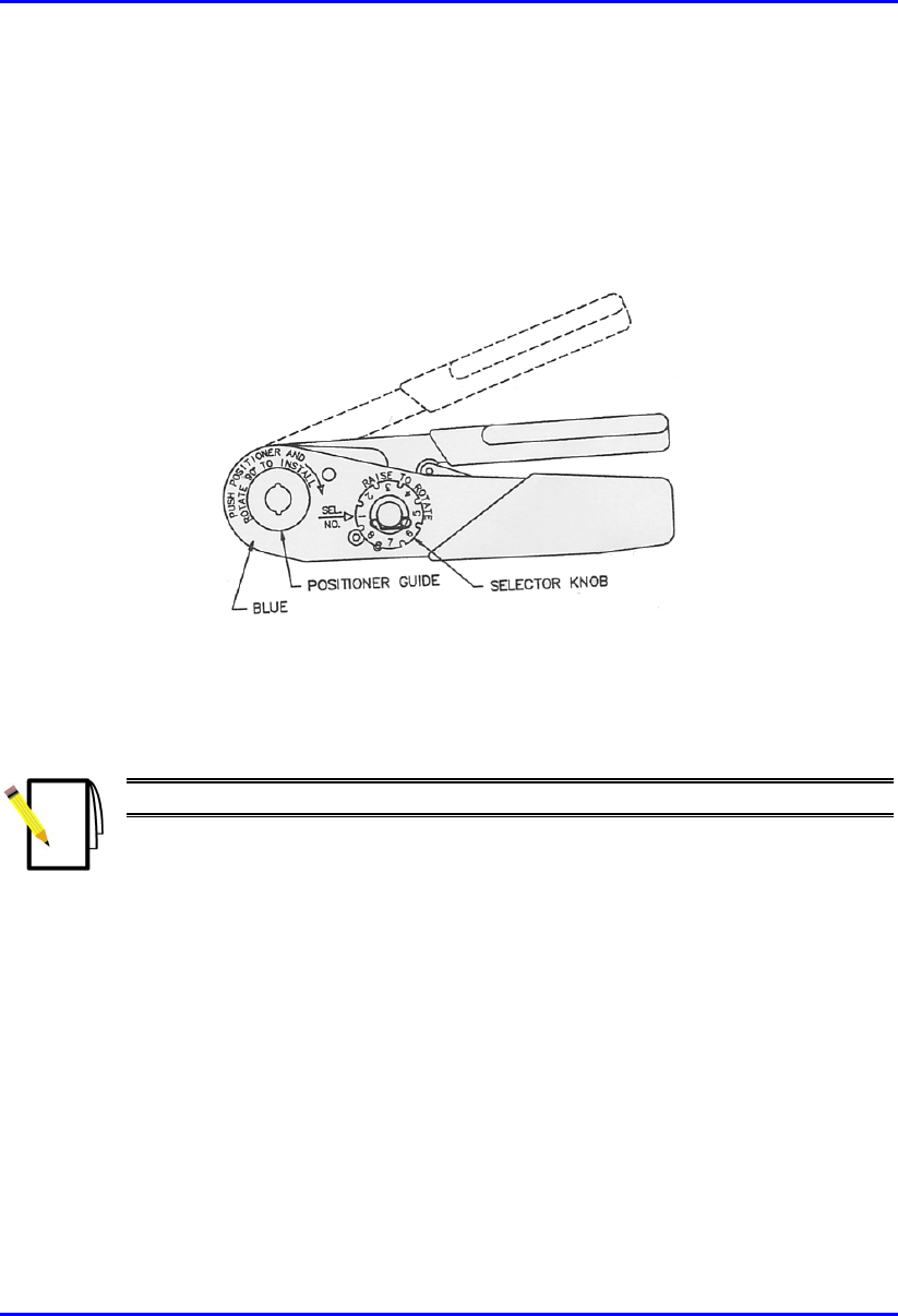
Hardware Installation Guide Cable Crimping
02030311-05 Airspan Networks Ltd. B-15
B.3. Crimping GPS Cable Connectors
Airspan recommends the following tools for crimping for N-type connectors:
! Crimping tool—Daniels AFM8 (M22520/2-01).
Figure B-8: Crimping tool – Daniels AFM8
Once you have housed the stripped cable, you can now crimp the cable to an N-type
connector.
Note: The crimper cannot be opened without completing the cycle.
To crimp the cable:
1. Ensure that the crimper is in the open position.
2. Remove safety clip from positioner guide.
3. Select the Positioner for contact to be crimped.
4. Insert the Positioner into the positioner guide and turn it 90 degrees until bayonet
pins lock.
5. Raise and rotate the Selector knob until the number indicated on data plate for
cable size to be crimped is in line with Sel. No. arrow.

Cable Crimping Hardware Installation Guide
B-16 Airspan Networks Ltd. 02030311-05
6. Insert the contact and prepared cable into the indenter opening from the side
opposite the Positioner.
7. Squeeze crimper handles together until the ratchet releases. The handle will
return to the open position.
8. Remove crimped contact and cable.

02030311-05 Airspan Networks Ltd. C-1
Technical Specifications
Technical SpecificationsTechnical Specifications
Technical Specifications
This appendix lists the technical specifications for the following WipLL units:
! WipLL Base Station equipment:
! Base Station Radio (BSR)
! Point-to-Point Radio (PPR)
! Base Station Distribution Unit (BSDU)
! Base Station Power Supply (BSPS)
! GPS antenna
! WipLL Customer premises equipment:
! Subscriber Premises Radio (SPR)
! Subscriber Data Adapter (SDA)
− SDA-1
− SDA-4H
− SDA-4S models
! Indoor Data Radio (IDR)
C

Technical Specifications Hardware Installation Guide
C-2 Airspan Networks Ltd. 02030311-05
C.1. Base Station WipLL Equipment
The following sub-sections list the specifications of the following WipLL Base
Station equipment:
! Base Station Radio (BSR)
! Point-to-Point Radio (PPR)
! Base Station Distribution Unit (BSDU)
! Base Station Power Supply (BSPS)

Hardware Installation Guide Technical Specifications
02030311-05 Airspan Networks Ltd. C-3
C.1.1. Base Station Radio (BSR)
Table C-1: BSR and MAC Specifications
Parameter Value Comment
Operating frequency range • 2.4 GHz
• 3.x GHz, MMDS, 2.8 GHz
• 5.8 GHz
• 900 MHz
• ISM band
• Licensed band
• Unlicensed band
• Unlicensed band
*Other ranges available for
trial
Spectrum spreading method Frequency hopping Per ETSI EN301 253
Duplex method • Time Division Duplex
(TDD) - 2.4 GHz, 2.8 GHz,
3.x GHz, MMDS, 900
MHz, and 5.8 GHz
• Frequency Division Duplex
(FDD) - 3.x GHz
Transmit bit rates Up to 4 Mbps BER and distance dependent
Channel spacing 1 MHz For 3.5 GHz the channel
spacing can be 1 MHz or 1.75
MHz
Output power from the BSR Up to 27 dBm, configurable at
2.4 GHz
Depending on local
regulations, maximum output
power can be configured at the
factory
Modulation method 8-level CPFSK
Channel access method PPMA / Adaptive TDMA
Protocol efficiency Up to 80% For large data packets
Number of SPR/IDR per BSR Up to 126
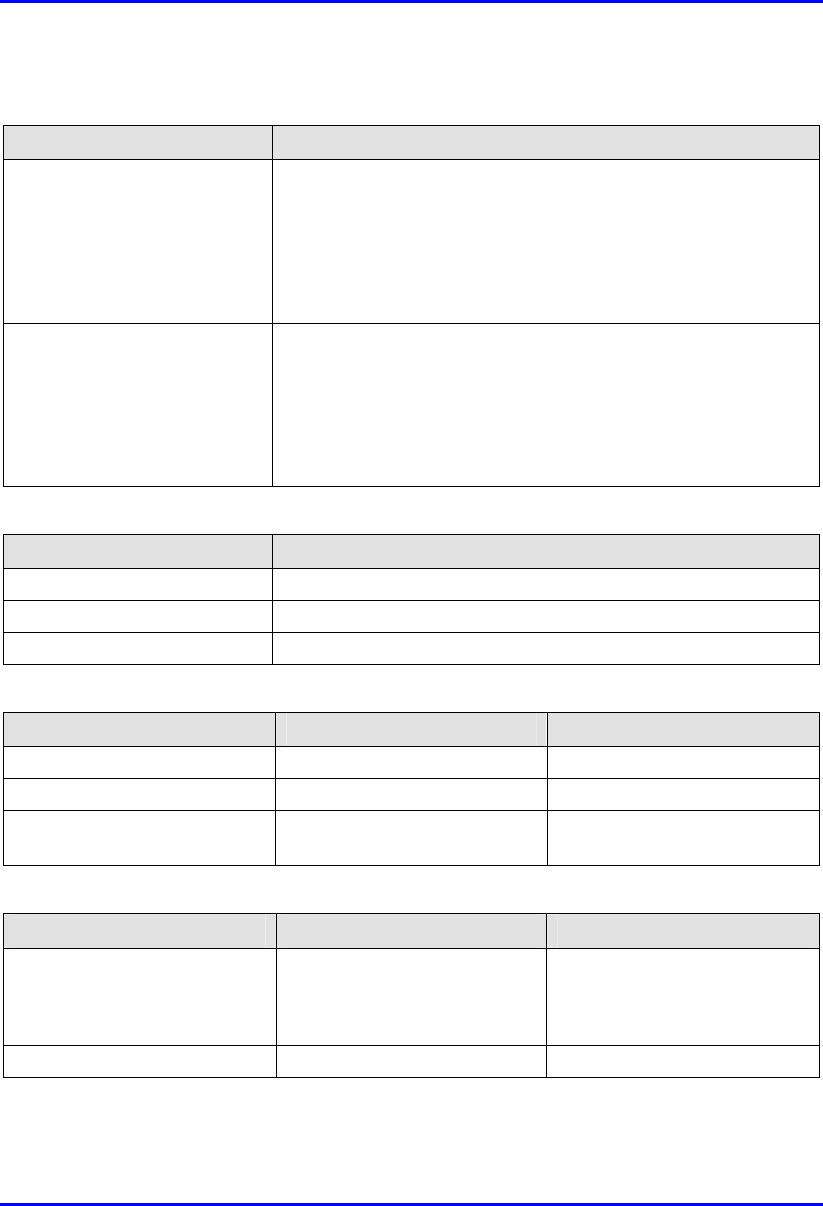
Technical Specifications Hardware Installation Guide
C-4 Airspan Networks Ltd. 02030311-05
Table C-2: BSR EMC and Radio Standards Compliance
Parameter Value
Radio Standards Compliance • ETSI EN 300 328-1
• ETSI EN 301 253
• FCC part 15
• RSS139
• Telec
EMC • ETSI ETS 300 826
• ETSI EN 300 385
• ETSI EN 300 386-2
• ETSI ETS 300 132-2
• FCC part 15
Table C-3: BSR Agency Certification
Parameter Value
Emissions / Immunity EN 300 339 EN 300 386-2 ETS 300 328
Safety EN / IEC 60950
Environmental ETS 300 019-2-x
Table C-4: BSR Network Specifications
Parameter Value Comment
Filtering Rate 10,500 frames/sec At 64 byte packets
Forwarding Rate 1,300 frames/sec At 64 byte packets
Routing table length 200 networks, including
subnets
Table C-5: BSR Power Requirements
Parameter Value Comment
Voltage
• Minimum:
• Maximum:
48 VDC nominal
• 30 VDC
• 55 VDC
Voltage is received from the
BSDU
Maximum Amperes: 500 mA
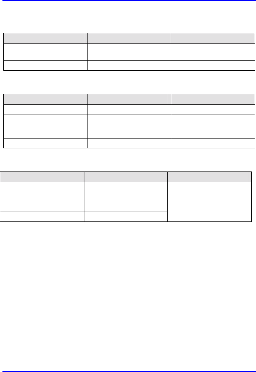
Hardware Installation Guide Technical Specifications
02030311-05 Airspan Networks Ltd. C-5
Table C-6: BSR Environmental Conditions
Parameter Value Comment
Operating temperature of
outdoor units (BSR and SPR)
-30ºC to +60ºC Optional range of -40ºC to
+70ºC
Storage temperature -40ºC to +80ºC
Table C-7: BSR Network Interface
Parameter Value Comment
Ethernet Network UTP EIA/TIA Category 5
Standards Compliance ANSI/IEEE 802.3 and
ISO/IEC 8802-3 10Base-T
compliant
Serial Port RS-232
Table C-8: BSR Physical Dimensions
Parameter Value Comment
Height 400 mm
Width 317 mm
Depth 65.5 mm
Weight 4.7 kg
Excluding mounting kit

Technical Specifications Hardware Installation Guide
C-6 Airspan Networks Ltd. 02030311-05
C.1.2. Point-to-Point Radio (PPR)
Table C-9: PPR Radio Specifications
Parameter Value
Operating frequency bands • 2,400 to 2,500 MHz
• 3,400 to 3,800 MHz
• 5,725 to 5,875 MHz
Duplex method • Time Division Duplex (TDD) for all bands
• Frequency Division Duplex (FDD) for 3.4 to 3.8 GHz
Radio Technology FH-CDMA
Multiple Access Method PPMA
Output power 27 dBm
Antenna type (built-in)
• PPR
• SPR
• 18 dBi / 15 dBi
• 18 dBi / 15 dBi
Sub-Channel Spacing 1 MHz
Modulation Multilevel (2, 4, or 8) CPFSK
Receiver Sensitivity (BER 1E-
6 at 2/4/8 FSK)
-90/ -83/ -75 dBm
Throughput Up to 4 Mbps per PPR-SPR link
Radio Standards Compliance • ETSI EN 300 328-1
• ETSI EN 301 253
• FCC part 15
• RSS139
• Telec
EMC • ETSI ETS 300 826
• ETSI EN 300 385
• ETSI EN 300 386-2
• ETSI ETS 300 132-2
• FCC part 15
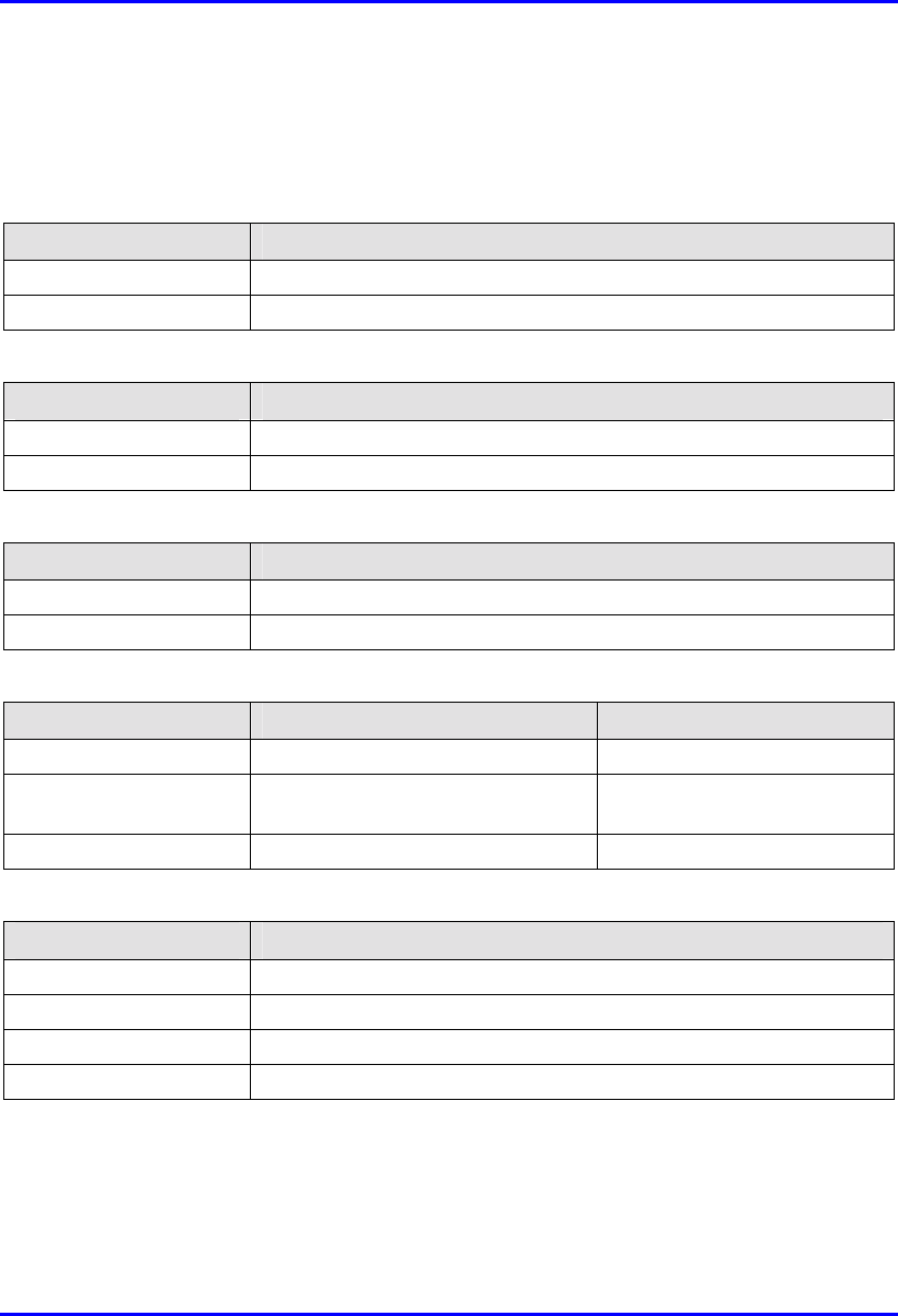
Hardware Installation Guide Technical Specifications
02030311-05 Airspan Networks Ltd. C-7
C.1.3. Base Station Distribution Unit (BSDU)
Table C-10: BSDU Network Specifications
Parameter Value
Filtering Rate 105,000 Frames / sec
Forwarding Rate 62,500 Frames / sec
Table C-11: BSDU Power Requirements
Parameter Value
Voltage 48VDC nominal
Power consumption Maximum 300W (including the feeding of 6 × BSRs)
Table C-12: BSDU Environmental Conditions
Parameter Value
Operating Temperature 0ºC to +50ºC
Storage Temperature -40ºC to +80ºC
Table C-13: BSDU Network Interface
Parameter Value Comment
Ethernet Network 100/10Base-T: UTP EIA/TIA Category 5
Standards Compliance ANSI/IEEE 802.3, ISO/IEC 8802-3
10/100 Base-T compliant
Serial Port RS-232
Table C-14: BSDU Physical Dimensions
Parameter Value
Height 4.32 cm
Width 48.26 cm
Depth 22.86 cm
Weight 2.9 kg
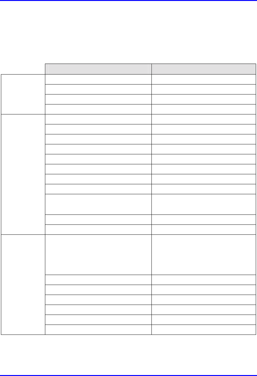
Technical Specifications Hardware Installation Guide
C-8 Airspan Networks Ltd. 02030311-05
C.1.4. Base Station Power Supply (BSPS)
Table C-15: BSPS Rectifier Specifications
Parameter Value
Voltage 90VAC to 270VAC
Current (nominal) 3.2A @ 230V / 4.3A @ 115V
Frequency 47Hz to 63Hz
Input
Power factor (nominal line/load) Greater or equal to 0.993
Voltage (default) 53.5VDC
Regulation (line & load) ±0.4%
Adjustable range 47 to 58 VDC
Current 12A @ 54V
Ripple & noise 50mVp-p
Efficiency (nominal load) 85% @ 230V / 82% @ 115V
Overload current <12A
Over-voltage protection 60 VDC
Over-temperature protection (measured
on case, upper panel corner)
• 80±5°C rectifier stops
• 72±5°C rectifier recovers
Walk-in time < 0.5 sec
Output
Hold-up time 40 ms
Withstand voltage (1 min) • 4230VDC INPUT/OUTPUT
• 2120VDC INPUT/GND
• 1700VDC OUTPUT/GND
Working temperature -10 to 45°C
Storage temperature -50 to 80°C
Dimensions (mm) 235 x 150 x 50 (L x W x H)
Weight 1100g
EMC Refer to system specifications
General
Safety According to: IEC950

Hardware Installation Guide Technical Specifications
02030311-05 Airspan Networks Ltd. C-9
Table C-16: BSPS DC Distribution Specifications
Parameter Value
Voltage 90VAC to 270VAC
Current (at full load)
N =Number of rectifier modules
• N*3.2A @ 230V
• N*4.3A @ 115V
Frequency 47 Hz to 63 Hz
Power factor (at full load) Greater or equal to 0.993
Input
Voltage (programmable) 42 to 60VDC ± 0.5VDC
Default float and boost voltage 54 and 57VDC respectively
Regulation (line, load, sharing) ±1%
Current N*12A (48A max.)
Psophometric noise -52 dBm (over 600 &)
Ripple & noise 50mVp-p
Efficiency (nominal load) 85% @ 230V / 82% @ 115V
Overload current < N*12A
Over-voltage protection 60VDC
Walk-in time < 1 sec
Hold-up time 40 ms
Output current indication 10 LED’s bar-graph
Active current sharing ±10% accuracy at full load
Output
Withstand voltage (1 min) 2120VDC INPUT/GND
Working temperature -10 ¸ 45°C
Storage temperature -50 ¸ 80°C
Dimensions (19” X 3U) Depth is 320mm W/O terminals,
360mm with terminals
Weight 13 kg (main unit + 3 rectifiers)
General
RS232 Communication 9600 bps, no-parity, 1 stop-bit
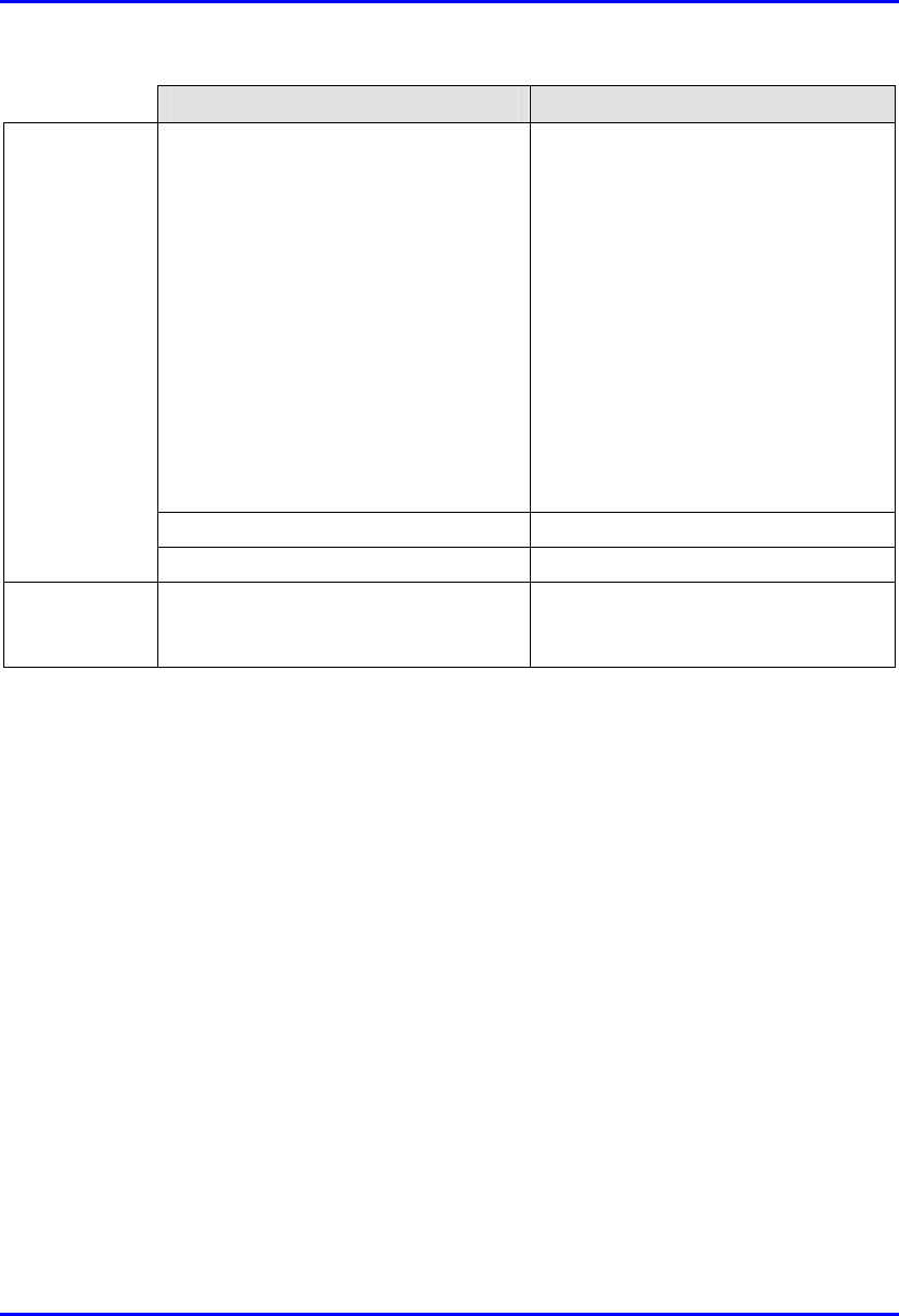
Technical Specifications Hardware Installation Guide
C-10 Airspan Networks Ltd. 02030311-05
Parameter Value
EMC According to:
• EN300-386-2 SUB 7.2.3
• EN55022 class B
• IEC1000-4-2
• IEC1000-4-3
• IEC1000-4-4
• IEC1000-4-5
• IEC1000-4-6
• IEC1000-4-11
• IEC1000-3-2
• IEC1000-3-3
Safety According to: IEC950
Maximum current withstand 2x70A
LVLD
(optional)
Trip voltage level Disconnect default: 43± 0.5 VDC, user
programmable Re-connect: with AC
recovery
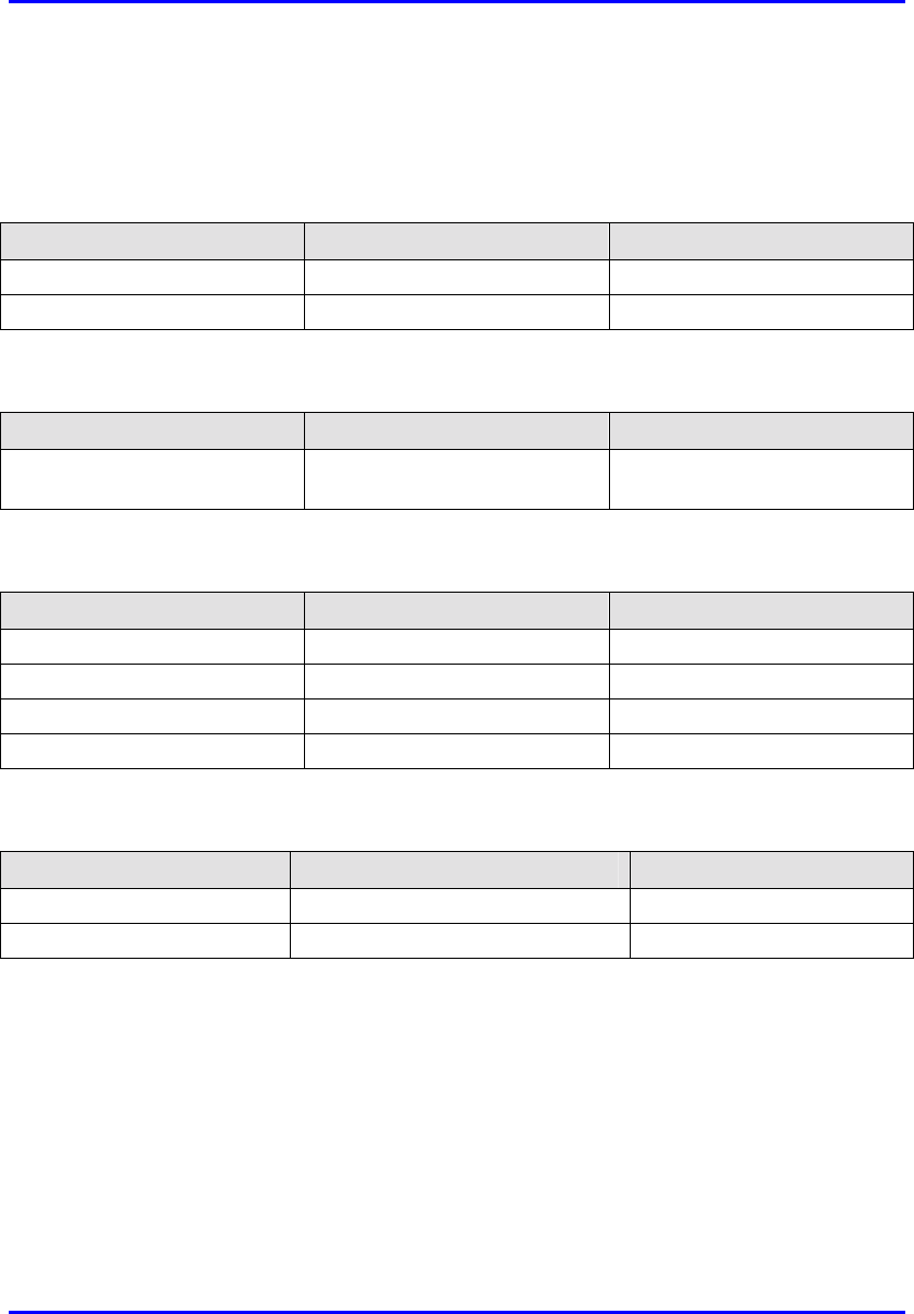
Hardware Installation Guide Technical Specifications
02030311-05 Airspan Networks Ltd. C-11
C.1.5. GPS antenna
Table C-17: SPR Power Requirements
Parameter Value Comment
Voltage Input 36 VDC Supplied by WipLL’s BSDU
Consumption 1.8W
Table C-18: Environmental Considerations
Parameter Value Comment
Operating temperature
-30ºC to +75ºC
Table C-19: GPS General
Parameter Value Comment
Input DGPS (Differential GPS)
Output 1 pulse per second
Standards Compliance MIL-STD 810E
Interface standard RS-422
Table C-20: GPS Dimensions
Parameter Value Comment
Diameter 115 mm
Height 90 mm

Technical Specifications Hardware Installation Guide
C-12 Airspan Networks Ltd. 02030311-05
C.2. Customer Premises WipLL Equipment
The following sub-sections list the specifications of the following WipLL CPE
equipment:
! Subscriber Premises Radio (SPR)
! Subscriber Data Adapter (SDA)
! Indoor Data Radio (IDR)
C.2.1. Subscriber Premises Radio (SPR)
Table C-21: SPR and MAC Specifications
Parameter Value Comment
Operating frequency • 2.4 GHz
• 3.x GHz, 2.8 GHz, MMDS
• 5.8 GHz
• ISM band
• Licensed band
• Unlicensed band
Spectrum spreading method Frequency hopping Per ETSI EN 301 253
Duplexing Method • Time Division Duplex (TDD)
2.4 GHz, 2.8 GHz, MMDS, 3.x
GHz, and 5.8 GHz
• Frequency Division Duplex
(FDD) 3.x GHz
Transmit Bit Rates Up to 4 Mbps BER and distance dependent
Channel spacing 1 MHz
Output power from the radio Up to 27 dBm, configurable at 2.4
GHz
Depending on local
regulations. Maximum
power output can be set at
the factory.
Modulation method 8 level CPFSK
Channel access method PPMA / Adaptive TDMA
Protocol efficiency Up to 80% For large data packets
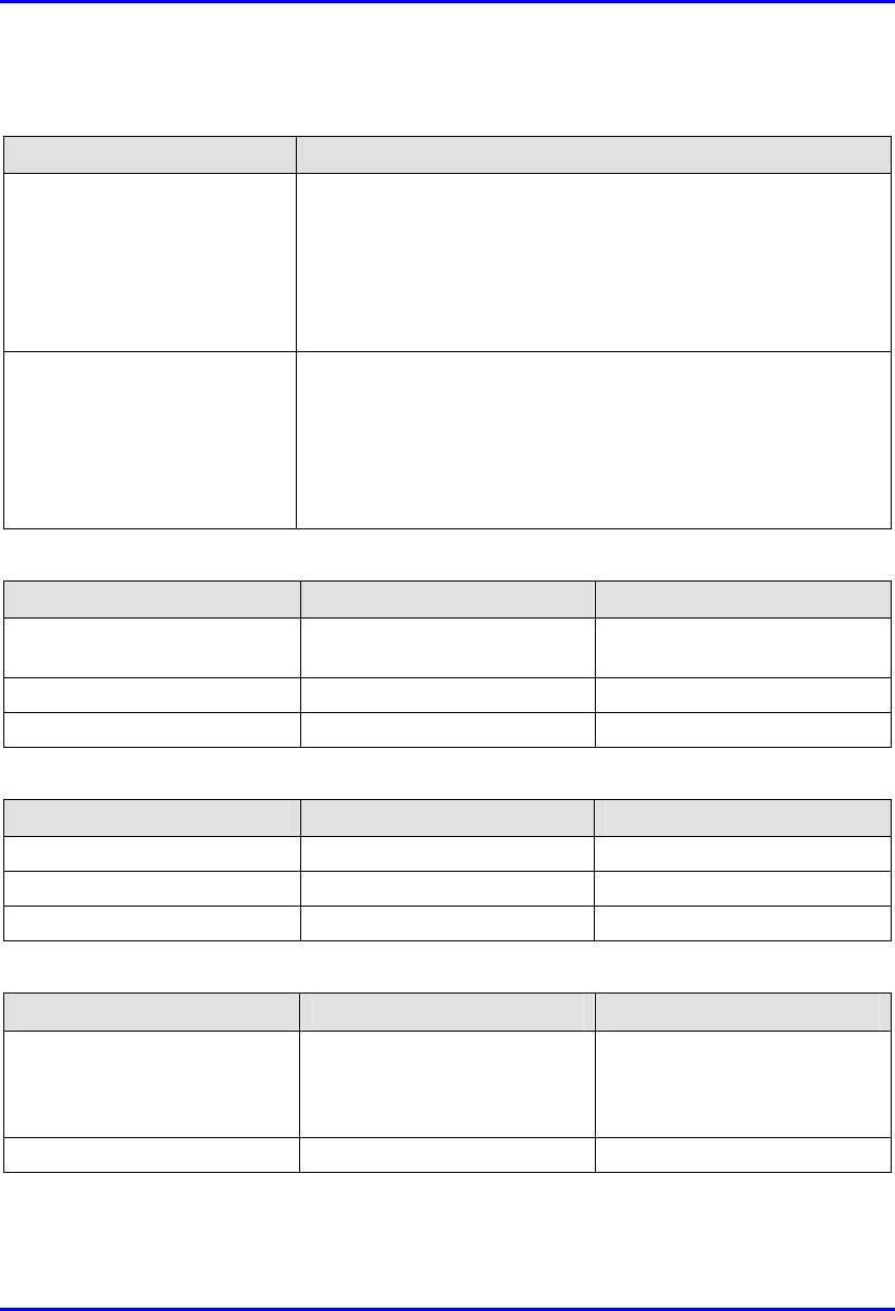
Hardware Installation Guide Technical Specifications
02030311-05 Airspan Networks Ltd. C-13
Table C-22: SPR EMC and Radio Standards Compliance
Parameter Value
Radio Standards Compliance • ETSI EN 300 328-1
• ETSI EN 301 253
• FCC part 15
• RSS139
• Telec
EMC • ETSI ETS 300 826
• ETSI EN 300 385
• ETSI EN 300 386-2
• ETSI ETS 300 132-2
• FCC part 15
Table C-23: SPR Agency Certification
Parameter Value Comment
Emissions / Immunity EN 300 339, EN 300 386-2,
ETS 300 328
Safety EN/IEC 60950
Environmental ETS 300 019-2-x
Table C-24: SPR Network Specifications
Parameter Value Comment
Filtering rate 10,500 frames / sec At 64 bytes
Forwarding rate 1,300 frames / sec At 64 bytes
Routing table length 16
Table C-25: SPR Power Requirements
Parameter Value Comment
• Voltage
• Minimum
• Maximum
• 48 VDC nominal
• 30 VDC
• 55 VDC
Power supplied from the SDA
Consumption Maximum 500 mA
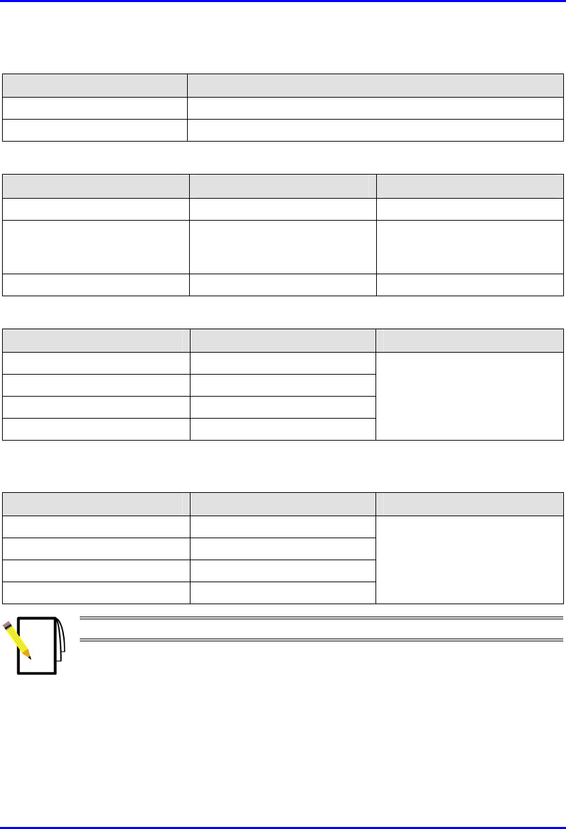
Technical Specifications Hardware Installation Guide
C-14 Airspan Networks Ltd. 02030311-05
Table C-26: Environmental Considerations
Parameter Value
Operating temperature -30ºC to +60ºC
Storage temperature -40ºC to +80ºC
Table C-27: Network Interface
Parameter Value Comment
Ethernet Network UTP EIA / TIA Category 5
Standards Compliance ANSI/IEEE 802.3 and
ISO/IEC 8802-3; 10BaseT
compliant
Serial Port RS-232
Table C-28: SPR Physical Dimensions (w/o High Gain Antenna)
Parameter Value Comment
Height 311 mm (12.24 inches)
Width 244 mm (9.6 inches)
Depth 65.5 mm (2.57 inches)
Weight 2.5 kg
Excluding mounting kit
Table C-29: SPR Physical Dimensions (with High Gain Antenna)
Parameter Value Comment
Height 400 mm (15.74 inches)
Width 317 mm (12.48 inches)
Depth 65.5 mm (2.57 inches)
Weight 4.7 kg
Excluding mounting kit
Note: The SPR cable and connector are the same as the BSR.

Hardware Installation Guide Technical Specifications
02030311-05 Airspan Networks Ltd. C-15
C.2.2. Subscriber Data Adapter (SDA)
C.2.2.1. SDA-1
Table C-30: SDA-1 Physical Dimensions
Parameter Value
Height 200 mm
Width 150 mm
Depth 40 mm
Weight 47 kg
Table C-31: SDA Power Requirements
Parameter Value
Output Voltage
-48VDC nominal
Power supply 110-240 VAC, 50/60Hz,
0.3-0.7A
Table C-32: SDA-1 Environmental Considerations
Parameter Value
Operating temperature
0ºC to +50ºC
Table C-33: SDA-1 Network Interfaces
Parameter Value
Data from SPR/BSR DB15
Ethernet RJ45 socket for a PC interface
Power AC power connector
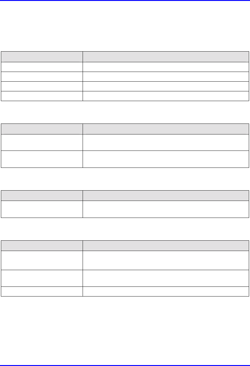
Technical Specifications Hardware Installation Guide
C-16 Airspan Networks Ltd. 02030311-05
C.2.2.2. SDA-4H
Table C-34: SDA-4-H Physical Dimensions
Parameter Value
Height 200mm
Width 150mm
Depth 40mm
Weight 53 kg
Table C-35: SDA-4H Power Requirements
Parameter Value
Output Voltage
-48VDC nominal
Power supply 110-240 VAC, 50/60Hz,
0.3-0.7A
Table C-36: SDA-4H Environmental Considerations
Parameter Value
Operating temperature
0ºC to +50ºC
Table C-37: SDA-4H Network Interfaces
Parameter Value
Data from SPR/BSR DB15
Ethernet Three RJ45 socket for a PC interface; one RJ-45 for cross over
connection
Power AC power connector
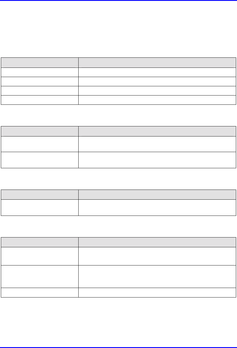
Hardware Installation Guide Technical Specifications
02030311-05 Airspan Networks Ltd. C-17
C.2.2.3. SDA-4S Models
Table C-38: SDA-4S Physical Dimensions
Parameter Value
Height 200 mm (7.87 inches)
Width 150 mm (5.9 inches)
Depth 40 mm (1.57 inches)
Weight 53 kg
Table C-39: SDA-4S Power Requirements
Parameter Value
Output Voltage
-48VDC nominal
Power supply 110-240 VAC, 50/60 Hz,
0.3-0.7A
Table C-40: SDA-4S Environmental Considerations
Parameter Value
Operating temperature
0ºC to +50ºC
Table C-41: SDA-4S Network Interfaces
Parameter Value
Data from SPR/BSR 15-pin D-type
Ethernet Four 8-pin RJ-45 10/100BaseT sockets for PC interface. These
ports support 10/100 Mbps Autosensing (Autonegotiation), and
MDI/MDI-X automatic crossover
Power AC power connector

Technical Specifications Hardware Installation Guide
C-18 Airspan Networks Ltd. 02030311-05
C.2.3. Indoor Data Radio (IDR)
Table C-42: IDR Radio and MAC Specifications
Parameter Value Comment
Operating frequency • 2.4 GHz
• 3.45 GHz
• 3.5 GHz
• 900 MHz
Spectrum spreading method Frequency hopping (Per ETSI ETS 300 328)
ARIB-STD-T66
Duplex Method • Time Division Duplex (TDD)
at 2.4 GHz and 900 MHz
• Frequency Division Duplex
(FDD) at 3.5 GHz and
3.45 GHz
Transmit Bit Rates Up to 4 Mbps Depending on BER
Channel spacing 1 MHz
Output power from the radio Up to 27 dBm, configurable at
2.4 GHz
Depending on local
regulations. Maximum
power output can be set at
the factory.
Channel access method PPMA
Protocol efficiency Up to 80% At BER = 10-5, depending
on the application
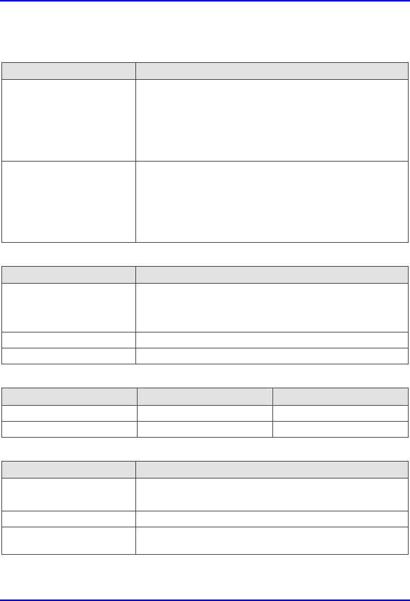
Hardware Installation Guide Technical Specifications
02030311-05 Airspan Networks Ltd. C-19
Table C-43: IDR EMC and Radio Standards Compliance
Parameter Value
Radio Standards Compliance • ETSI EN 300 328-1
• ETSI EN 301 253
• FCC part 15
• RSS139
• Telec
EMC • ETSI ETS 300 826
• ETSI EN 300 385
• ETSI EN 300 386-2
• ETSI ETS 300 132-2
• FCC part 15
Table C-44: IDR Agency Certification
Parameter Value
Emissions / Immunity • VCCI Class A
• ARIB-STD-T66
• ETSI 300 386-2
Safety EN/IEC 60950
Environmental ETS 300 019-2-x
Table C-45: IDR Network Specifications
Parameter Value Comment
Filtering rate 10,500 frames/sec At 64 bytes
Forwarding rate 1,300 frames/sec At 64 bytes
Table C-46: IDR Power Requirements
Parameter Value
External Power Supply
Voltage
• Minimum: 100 VAC
• Maximum: 240VAC
Operating Frequency Range 50 to 60 Hz
Maximum Power
consumption
Less than 15W
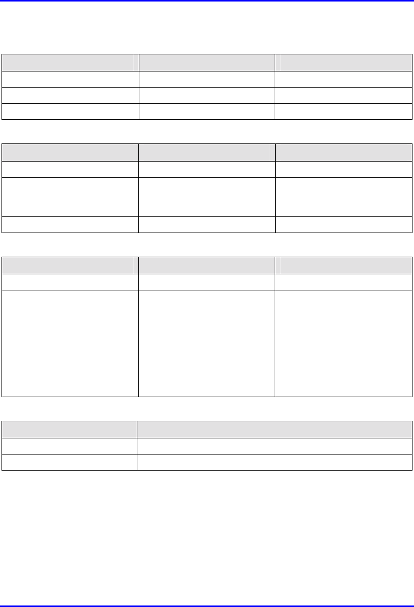
Technical Specifications Hardware Installation Guide
C-20 Airspan Networks Ltd. 02030311-05
Table C-47: IDR Environmental Considerations
Parameter Value Comment
Operating temperature 0-50ºC
Operating Humidity +30Cº 93% Maximum humidity
Storage temperature -40 – 70ºC
Table C-48: IDR Network Interface
Parameter Value Comment
Ethernet Network UTP EIA / TIA Category 5
Standards Compliance ANSI/IEEE 802.3 and
ISO/IEC 8802-3 10Base-T
compliant
Serial Port RJ-11
Table C-49: IDR Physical Dimensions
Parameter Value Comment
Weight 1,430 g
Dimensions (H x W x D)
• 155 mm (6.1 inches) x 233
mm (9.17 inches) x 74.5
mm (2.93 inches)
• 120.5 mm (4.74 inches) x
61mm (2.4 inches) x 35
mm (1.37 inches)
• IDR with built-in antenna
• IDR with an external
antenna
Note: Dimensions exclude the
external power adapter.
Table C-8: IDR Pole Mounting Dimensions
Parameter Value
Minimum pole diameter 35 mm (1.37 inches)
Maximum pole diameter 50 mm (1.97 inches)

02030311-05 Airspan Networks Ltd. D-1
Summary of Connector
Summary of Connector Summary of Connector
Summary of Connector
Pinouts
PinoutsPinouts
Pinouts
This appendix provides a summary of the connector pinouts for the WipLL devices.
D.1. BSR/SPR-to-BSDU/SDA CAT 5 Connector
Pinouts
Table D-1 describes the 15-pin D-type connector pinouts for the CAT 5 cable that
connects the BSR's/SPR's 15-pin D-type port to the BSDU's/SDA's 15-pin D-type
port.
Table D-1: 15-pin D-type to 15-pin D-type connector pinouts
BSR/SPR BSDU/SDA 15-pin
D-type
male Pin Function
Wire color Wire
pair Pin Function
1 +48 VDC Blue / white 1 +48 VDC
2 -48 VDC Blue
1
2 -48 VDC
3 Tx+ Orange / white 3 Rx+
4 Tx- Orange
2
4 Rx-
5 Rx+ Green / white 5 Tx+
6 Rx- Green
3
6 Tx-
7 Sync.+ Brown / white 7 Sync.+
8 Sync.- Brown
4
8 Sync.-
D
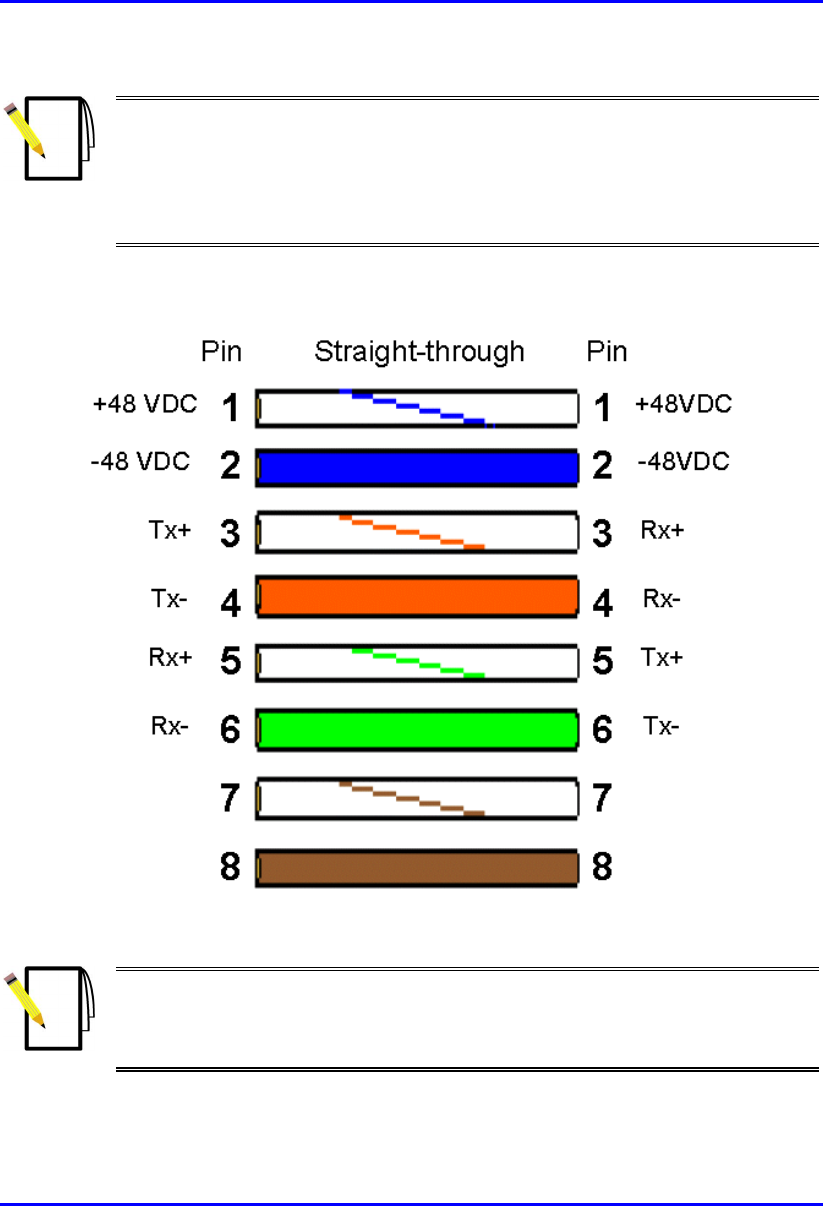
Summary of Connector Pinouts Hardware Installation Guide
D-2 Airspan Networks Ltd. 02030311-05
Notes:
- Pins 9 through 15 of the 15-pin D-type connector are not used.
- The wire color-coding described in the table is WipLL's standard for wire
color-coding. However, if you implement your company's wire color-coding
scheme, ensure that the wires are paired and twisted according to the pin
functions listed in Table D-1 (e.g., Rx+ with Rx-).
WipLL uses the following wire color-coding standards for CAT 5 cables with 15-pin
D-type to 15-pin D-type connectors on either ends (8 wires used):
Figure D-1: WipLL wire color-coding for 15-pin D-type connectors
Note: The wires are twisted together in pairs, for example, blue/white with
blue, and orange/white with orange. This prevents electrical interference
between the transmitter pins. For example, pin 3 (Tx+; orange / white) is paired
and twisted with pin 4 (Tx-; orange).
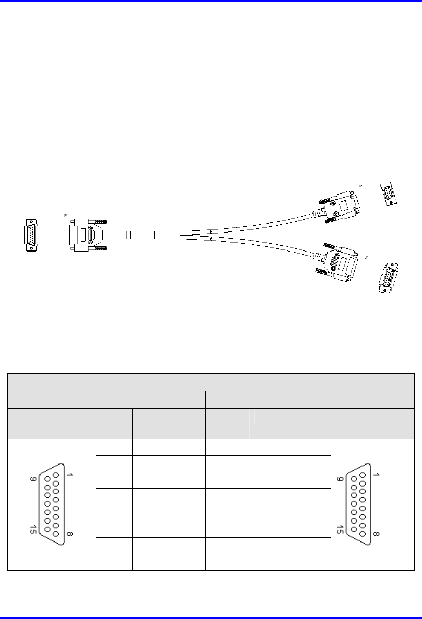
Hardware Installation Guide Summary of Connector Pinouts
02030311-05 Airspan Networks Ltd. D-3
D.2. SPR Serial Connector Pinouts
For BSR and SPR serial connections, a Y-cable is used. The Y-cable connects the
BSR and SPR to the BSDU and SDA, respectively, as well as to the PC running the
WipLL management application.
Figure D-2 displays the Y-cable used to split the BSR/SPR 15-pin D-type port into
two.
Figure D-2: Y-cable for serial connection
Connector pinouts are described in the following tables:
Table D-2: Y-cable SPR-to-SDA connector pinouts
Straight-through Y-cable
SPR SDA
15-pin D-type
male
Pin Function Pin Function 15-pin D-type
male
1 0 VDC 1 +48 VDC
2 +48 VDC 2 -48 VDC
3 Ethernet Tx+ 3 Rx+
4 Ethernet Tx- 4 Rx-
5 Ethernet Rx+ 5 Tx+
6 Ethernet Rx- 6 Tx-
7 Hop Sync+ 7 Sync.+
8 Hop Sync- 8 Sync.-
15-pin D-type
male
PC
SDA
15-pin D-type
male
9-pin D-type
female
SPR
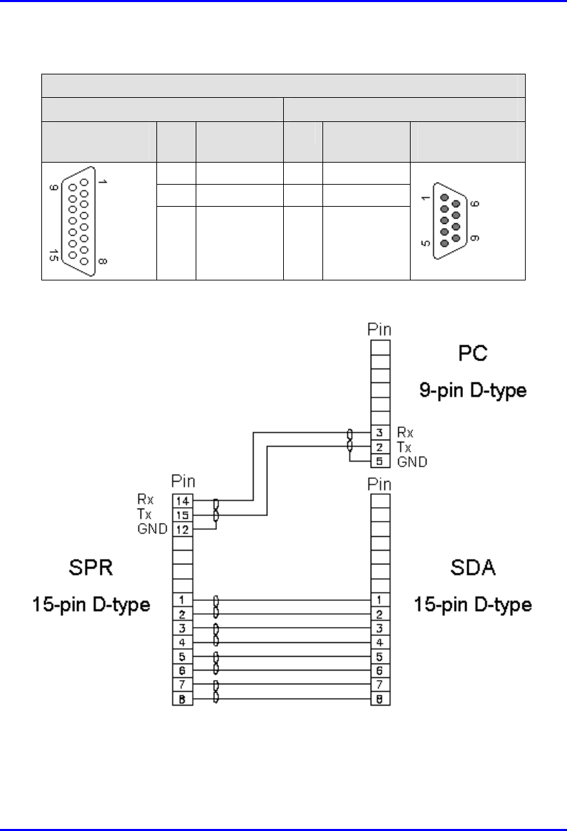
Summary of Connector Pinouts Hardware Installation Guide
D-4 Airspan Networks Ltd. 02030311-05
Table D-3: Y-cable SPR-to-PC connector pinouts
Straight-through Y-cable
SPR PC
15-pin D-type
male
Pin Function Pin Function 9-pin D-type
female
12 GND 5 GND
14 RS232 Rx 3 Rx
15 RS232 Tx 2 Tx
The Y-cable connector pin assignments are displayed shematically in Figure D-3.
Figure D-3: Y-cable connector pin assignment
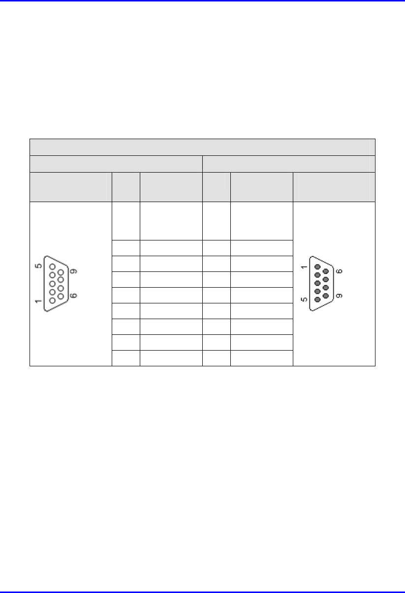
Hardware Installation Guide Summary of Connector Pinouts
02030311-05 Airspan Networks Ltd. D-5
D.3. BSR Serial Connector Pinouts
The BSR provides a serial port for RS-232 serial interface to a PC. This serial
communication connection allows you to perform BSR initial configuration.
Table D-4: BSR-to-PC serial connector pinouts
Crossover serial cable
BSR PC
9-pin D-type
male
Pin Function Pin Function 9-pin D-type
female
1 Not
connected
(NC)
1 NC
2 RS232 Rx 3 Tx
3 RS232 Tx 2 Rx
4 NC 6 NC
5 GND 5 GND
6 NC 4 NC
7 NC 8 NC
8 NC 7 NC
9 NC 9 NC
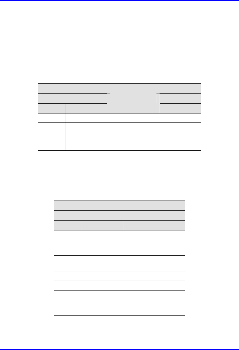
Summary of Connector Pinouts Hardware Installation Guide
D-6 Airspan Networks Ltd. 02030311-05
D.4. BSDU Connector Pinouts
D.4.1. BSDU Daisy Chaining
Table D-5: BSDU daisy chaining connector pinouts
Crossover cable
8-pin RJ-45 8-pin RJ-45
Pin Name
Description
Pin
1 Tx+ Transmit Data+ 3
2 Tx- Transmit Data- 6
3 Rx+ Receive Data+ 1
6 Rx- Receive Data- 2
D.4.2. BSDU Synchronization
! Sync IN
Table D-6: BSDU synchronization (Sync IN) connector pinouts
Straight-through cable
8-pin RJ-45 male
Pin Name Description
1 TD+ Transmit data to GPS
2 TD- Transmit data from
GPS
3 Rx+ Receive Data (hop
synchronization)
4 NC Not connected
5 NC Not connected
6 Rx- Receive Data (hop
synchronization)
7 1PPS+ GPS pulse per second
8 1PPS- GPS pulse per second
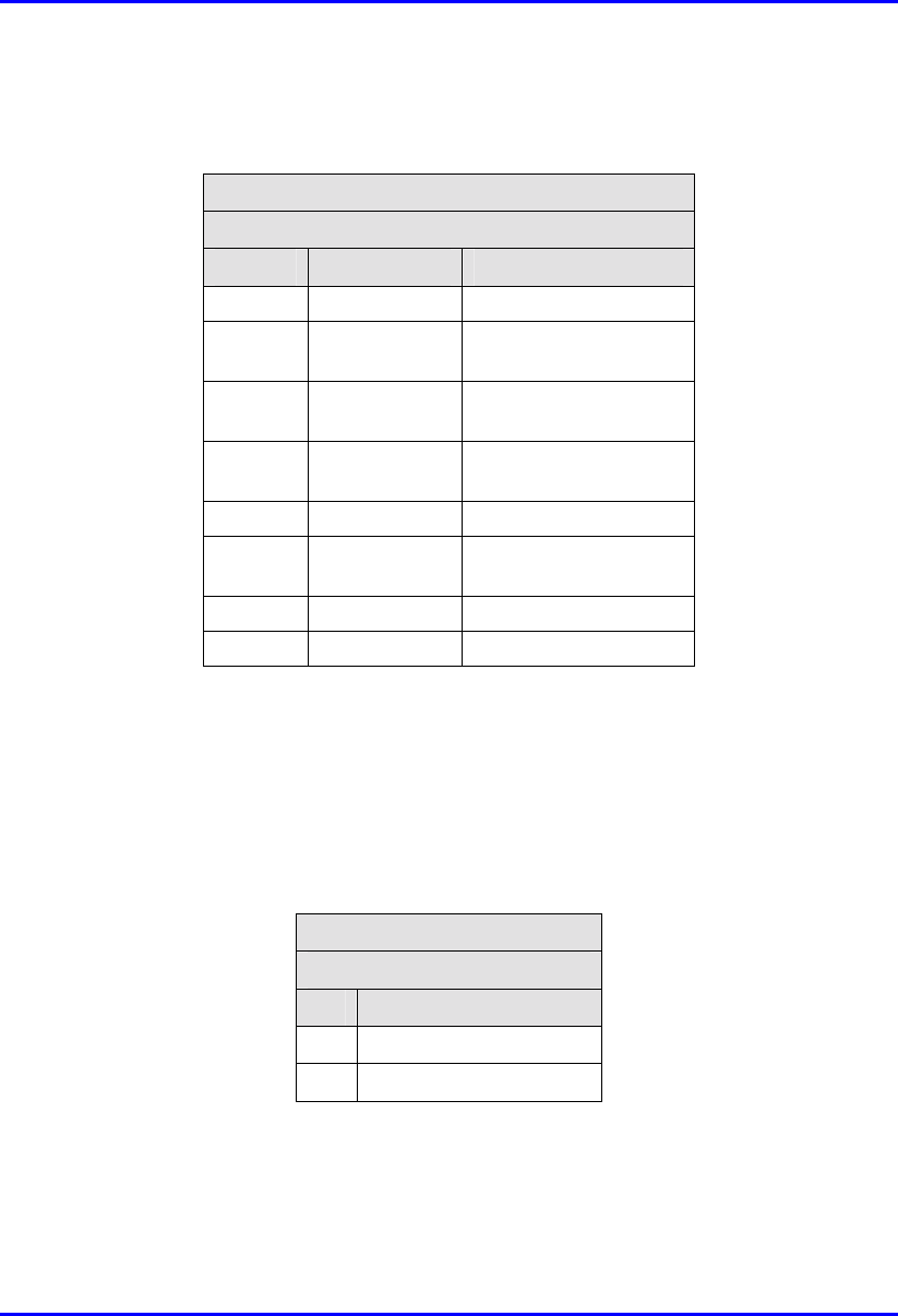
Hardware Installation Guide Summary of Connector Pinouts
02030311-05 Airspan Networks Ltd. D-7
! Sync OUT
Table D-7: BSDU synchronization (Sync OUT) connector pinouts
Straight-through cable
8-pin RJ-45 male
Pin Name Description
1 TD+ Transmit data to GPS
2 TD- Transmit data from
GPS
3 Tx+ Transmit Data (hop
synchronization)
4 RD+ Receive Data (from
GPS)
5 RD- Receive Data (to GPS)
6 Tx- Transmit Data (hop
synchronization)
7 1PPS+ GPS pulse per second
8 1PPS- GPS pulse per second
D.4.3. BSDU Serial Management
The BSDU’s serial management 9-Pin D-type port (labeled Monitor) allows you to
connect the WipLL’s network management system (WipConfig) to BSDU without
assigning BSDU an IP address.
Table D-8: BSDU serial management connector pinouts
Straight-through
9-Pin D-type male
Pin Signal
2 Rx
3 Tx
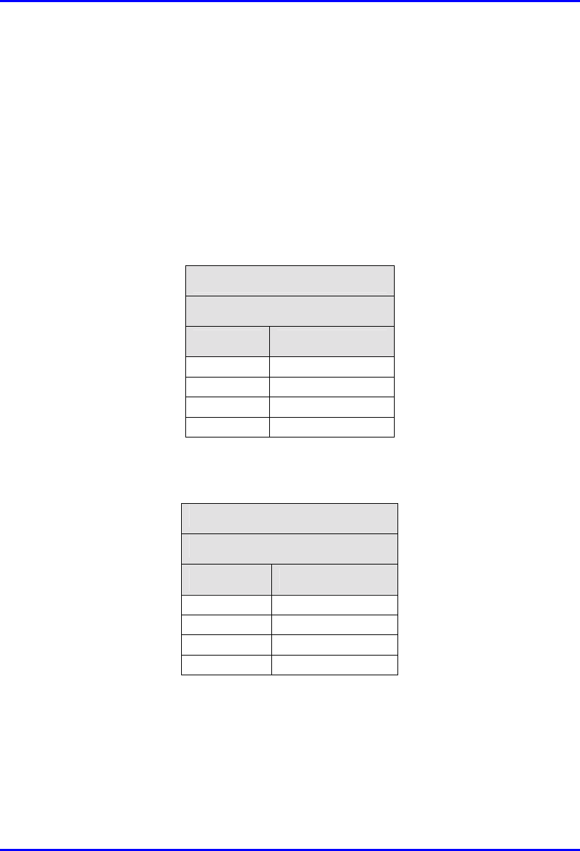
Summary of Connector Pinouts Hardware Installation Guide
D-8 Airspan Networks Ltd. 02030311-05
D.4.4. BSDU PC Network Management
For BSDU network management, you can connect the BSDU’s two 10BaseT ports
(i.e., loop the ports) to one another by a crossover cable, then connect the PC to one
of the BSDU’s 100BaseT ports. If the two BSDU 10BaseT ports are not connected
to one another, then you need to connect the PC to the BSDU’s right-most 10BaseT
port (labeled 10Base-T 2).
! Looping two 10Base-T ports:
Table D-9: BSDU 10Base-T connector pinouts for looping
Crossover cable
8-pin RJ-45 male
Pin Signal
1 +Rx
2 -Rx
3 +Tx
6 -Tx
! 100Base-T port connected to PC
Table D-10: BSDU 100Base-T connector pinouts for management
Straight-through cable
8-pin RJ-45
Pin Function
1 +Tx
2 -Tx
3 +Rx
6 -Rx
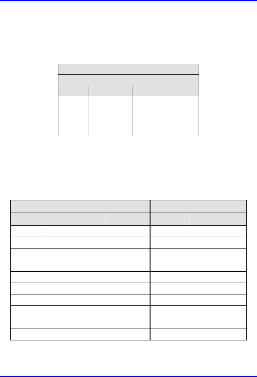
Hardware Installation Guide Summary of Connector Pinouts
02030311-05 Airspan Networks Ltd. D-9
D.4.5. BSDU 100Base-T
Table D-11: BSDU 100Base-T LAN/WAN connector pinouts
Straight-through cable
8-pin RJ-45
Pin Name Description
1 Tx+ Transmit Data+
2 Tx- Transmit Data-
3 Rx+ Receive Data+
6 Rx- Receive Data-
D.5. GPS-to-BSDU Connector Pinouts
The following table lists the connector pinouts for the cable connecting the GPS
antenna to the BSDU.
Table D-12: GPS-to-BSDU connector pinouts
12-pin female (GPS) 15-pin D-type male (BSDU)
Pin Pin name Cable color Pin Lead
1 POWER Red 9
2 RX_DATA_1-
Blue 5 TD+ (after R5)
3 RX_DATA_1+
Black 6 TD-
4 TX_DATA_1-
Yellow 4 RD-
5 TX_DATA_1+
Black 3 RD+ (after R3)
6 RX_DATA_2-
Brown x
7 RX_DATA_2+
Black x
9 GND Black 10
11 1PPS+ Green 8 1PPS-
12 1PPS- Black 7 1PPS+ (After R7)
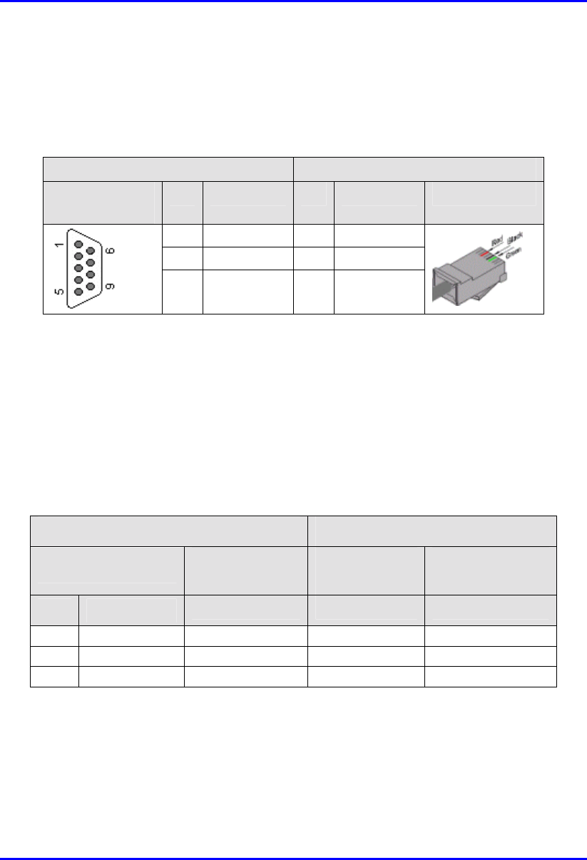
Summary of Connector Pinouts Hardware Installation Guide
D-10 Airspan Networks Ltd. 02030311-05
D.6. Connector Pinouts for BSPS Serial
Management via BSDU
Table D-13: BSPS serial management connector pinouts
BSDU BSPS
9-pin D-type
female
Pin Function Pin Function 8-pin RJ-45
2 Rx 6 Tx
3 Tx 3 Rx
5 GND 5 GND
D.7. IDR Connector Pinouts
D.7.1. Serial Management Connection
Serial connection of the IDR to a PC is performed by connecting the IDR's RJ-11
port to the serial port (9-pin D-type) of the PC.
Table D-14: IDR serial management connector pinouts
Straight-through cable (IDR side) Crossover cable (PC side)
6-Pin RJ-11 male 9-Pin D-type
female
9-Pin D-type
male
9-Pin D-type
female
Pin Function Pin Pin Pin
1 Rx 2 4 3
5 G
N
D 5 1 5
6 Tx 3 3 2
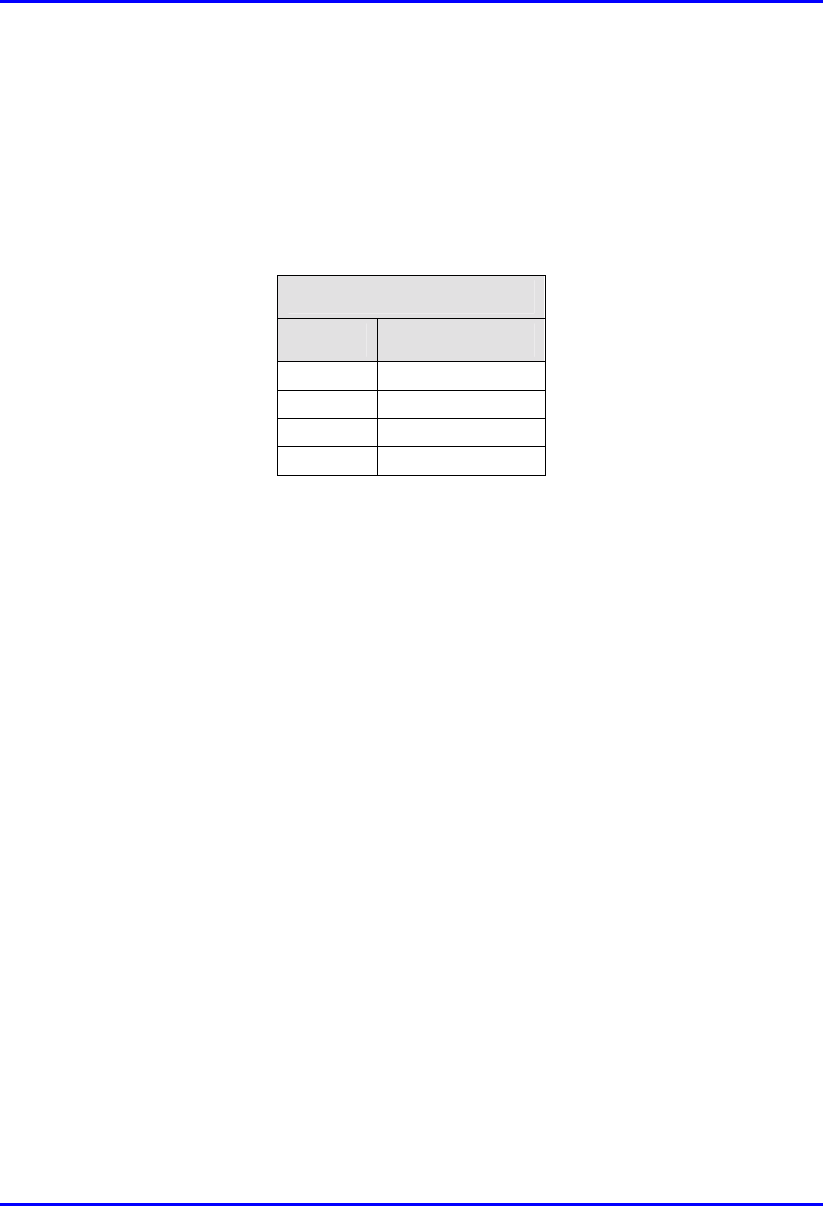
Hardware Installation Guide Summary of Connector Pinouts
02030311-05 Airspan Networks Ltd. D-11
D.7.2. Ethernet LAN Connection
The table below describes the connector pinouts for the Ethernet cable (CAT 5) that
connects the IDR’s Ethernet port to the PC’s LAN port, using an 8-pin RJ-45
connector.
Table D-15: BSPS Ethernet LAN connector pinouts
8-pin RJ-45
Pin Function
1 Rx+
2 Rx-
3 Tx+
6 Tx-
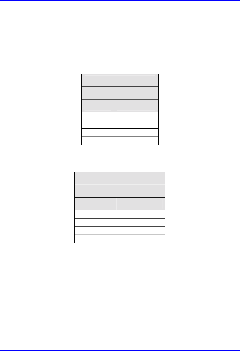
Summary of Connector Pinouts Hardware Installation Guide
D-12 Airspan Networks Ltd. 02030311-05
D.8. SDA Ethernet LAN Connector Pinouts
! For SDA-1, SDA-4H (J2, J3, J4), and SDA-4S models (also for VoIP networks):
Table D-16: SDA Ethernet LAN connector pinouts
Straight-through cable
8-pin RJ-45 male
Pin Function
1 +RX
2 -RX
3 +TX
6 -TX
! For J5 port on the SDA-4H:
Table D-17: SDA Ethernet LAN connector pinouts
Crossover cable
8-pin RJ-45 male
Pin Function
1 +Tx
2 -Tx
3 +Rx
6 -Rx