Airspan Networks AIRSPAN-BSR900 Base Station Radio (BSR) User Manual Part 2B
Airspan Networks Inc Base Station Radio (BSR) Users Manual Part 2B
Contents
- 1. Users Manual Part 1
- 2. Users Manual Part 2A
- 3. Users Manual Part 2B
- 4. Users Manual Part 3
Users Manual Part 2B
Installing the BSDU Hardware Installation Guide
5-10 Airspan Networks Ltd. 02030311-05
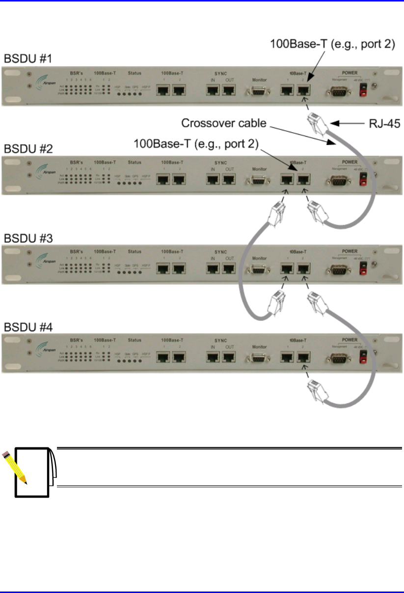
Figure 5-5: Cable connections for BSDU daisy chaining
Note: When daisy-chaining BSDUs, it does not matter which 100Base-T ports
you use to connect two BSDUs. For example, you can connect 100Base-T 1 to
100Base-T 2, or 100Base-T 1 to 100Base-T 1.

Hardware Installation Guide Installing the BSDU
02030311-05 Airspan Networks Ltd. 5-11
5.8. Connecting Sync IN/OUT ports
The BSDU’s front panel provides an in/out synchronization 8-Pin RJ-45 ports for
synchronization between BSDUs at the base station. The SYNC OUT of the master
BSDU is connected to the SYNC IN of a slave BSDU, which then connects its
SYNC OUT to the SYNC IN of another slave BSDU, and so on.
! Connector: 8-Pin RJ-45 (male)
! Cable: straight-through cable
! Connector Pinouts:
! Sync IN
Pin Name Description
1 TD+ Transmit data to GPS
2 TD- Transmit data from
GPS
3 Rx+ Receive Data (hop
synchronization)
4 NC Not connected
5 NC Not connected
6 Rx- Receive Data (hop
synchronization)
7 1PPS+ GPS pulse per second
8 1PPS- GPS pulse per second

Installing the BSDU Hardware Installation Guide
5-12 Airspan Networks Ltd. 02030311-05
! Sync OUT
Pin Name Description
1 TD+ Transmit data to GPS
2 TD- Transmit data from
GPS
3 Tx+ Transmit Data (hop
synchronization)
4 RD+ Receive Data (from
GPS)
5 RD- Receive Data (to GPS)
6 Tx- Transmit Data (hop
synchronization)
7 1PPS+ GPS pulse per second
8 1PPS- GPS pulse per second
Hardware Installation Guide Installing the BSDU
02030311-05 Airspan Networks Ltd. 5-13
5.9. Connecting to BSPS for Power
Management
The BSDU’s front panel provides a 9-Pin DB-type port for serial RS-232 power
management of the BSPS. WipLL’s WipManage manages BSPS by connecting to
the BSDU through the IP network (i.e., from the BSR), and then manages BSPS
through the serial connection between the BSDU and BSPS. The reason for the
serial connection is that the BSPS does not support SNMP-based management,
which is the basis of WipManage.
! Connector: depending on the BSPS model:
! 9-Pin D-type female (BSDU and BSPS)
-Or-
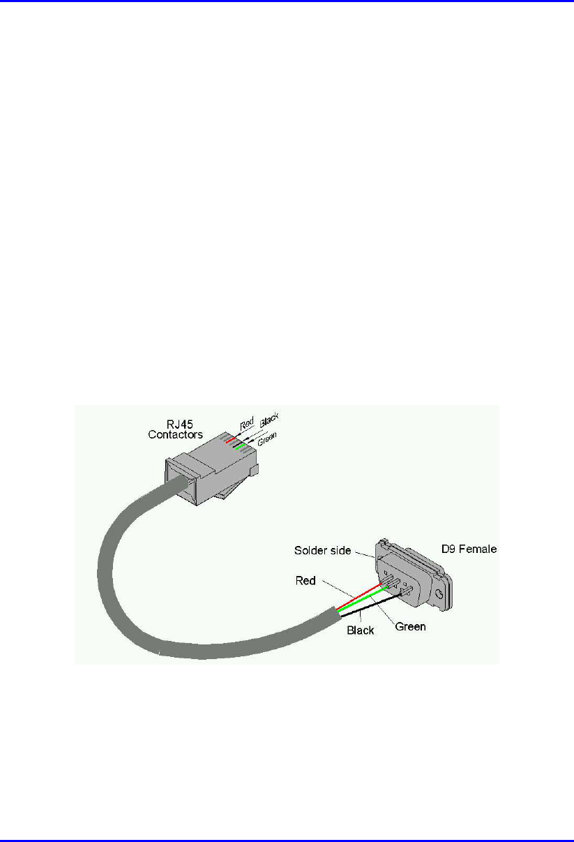
! 9-Pin D-type female (BSDU) to 8-Pin RJ-45 (BSPS) adapter (see Figure 5-6)
Figure 5-6: BSDU-to-BSPS power management connectors (RJ-45 to 9-Pin D-type
cable adapter)
! Cable length: 60 cm

Installing the BSDU Hardware Installation Guide
5-14 Airspan Networks Ltd. 02030311-05
! Connector pinouts:
BSDU BSPS
9-Pin D-type RJ-45
Pin Name Description Pin Name
1 NC Not connected 1 NC
2 Rx Receive Data 2 NC
3 Tx Transmit Data 3 Rx
4 NC Not connected 4 NC
5 GND Ground 5 GND
6 NC Not connected 6 Tx
7 NC Not connected 7 NC
8 NC Not connected 8 NC
9 NC Not connected
To connect the BSDU to the BSPS for BSPS serial power management:
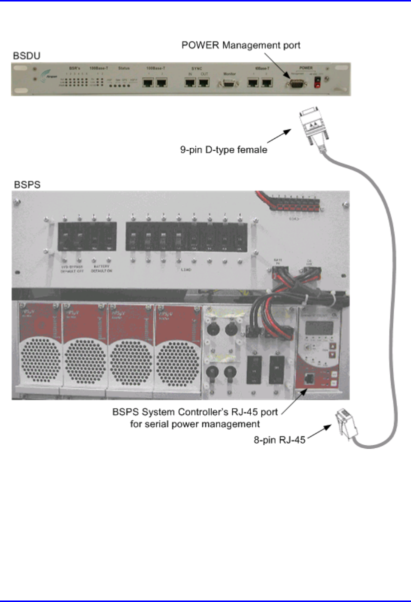
1. Connect the 9-pin D-type female connector, at one end of the cable, to the
BSDU’s 9-pin D-type port labeled POWER Management (see Figure 5-7).
2. Connect the RJ-45 connector, at the other end of the cable, to the BSPS System
Controller’s RJ-45 serial port (see Figure 5-7).
Hardware Installation Guide Installing the BSDU
02030311-05 Airspan Networks Ltd. 5-15
Figure 5-7: BSDU-to-BSPS serial cable connections for BSPS power management

Installing the BSDU Hardware Installation Guide
5-16 Airspan Networks Ltd. 02030311-05
5.10. Connecting to PC for Serial Management
The BSDU’s front panel provides a 9-Pin D-type port for BSDU serial management
(labeled Monitor). Serial management allows you to connect the WipLL’s network
management system (WipConfig) to BSDU without assigning BSDU an IP address.
! Connector: 9-pin D-type male
! Cable: straight-through
! Connector pinouts:
9-Pin D-type Connector
Pin Signal
1 Not connected (NC)
2 Rx
3 Tx
4 NC
5 NC
6 NC
7 NC
8 NC
9 NC
Hardware Installation Guide Installing the BSDU
02030311-05 Airspan Networks Ltd. 5-17
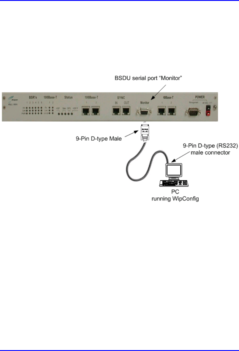
To connect the PC to the BSDU by serial connection (see Figure 5-8):
1. Connect the 9-pin D-type female connector to the PC.
2. Connect the 9-pin D-type male connector, at the other end of the cable, to the
BSDU’s serial port (labeled Monitor).
Figure 5-8: PC-to-BSDU Serial Connections
Installing the BSDU Hardware Installation Guide
5-18 Airspan Networks Ltd. 02030311-05
5.11. Connecting to PC for Network IP
Management
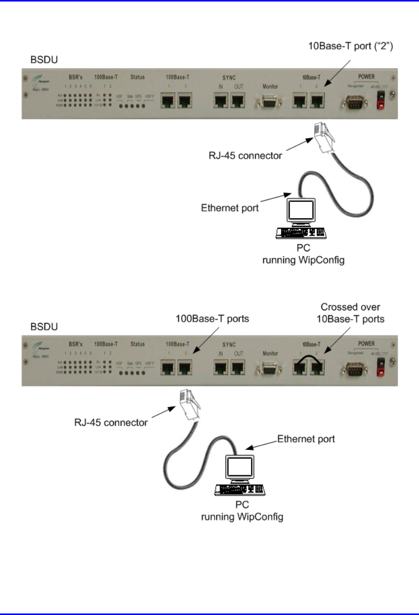
For network (IP) configurations, you can connect the PC to the BSDU’s local port,
or remotely (from anywhere) if you have IP connectivity to the device. For PC-to-
BSDU local network (IP) connections you need to connect the PC to the BSDU’s
10BaseT or 100BaseT port. The BSDU’s front panel provides two 10Base-T ports:
left is labeled 10Base-T 1; right is labeled 10Base-T 2. Port 1 provides PC
management interface to all BSRs connected to the BSDU. Port 2 provides
management interface only to the BSDU. If you connect the BSDU’s two 10BaseT
ports (i.e., loop the ports) to one another by a crossover cable, then you can connect
the PC to one of the BSDU’s 100BaseT ports. If the two BSDU 10BaseT ports are
not connected to one another, then you need to connect the PC to the BSDU’s right-
most 10BaseT port (labeled 10Base-T 2).
Note: For WipLL management, it is recommended to connect Port 1 to Port 2
by a crossover cable, and then connect the management station (PC) to one o
f
the 100Base-T ports. In such a setup, you can provide management to all
daisy-chained BSDUs and their associated BSRs through one 100Base-T port.
! Connector: 8-Pin RJ-45 (male)
! Cables:
! Crossover cable for looping the two 10BaseT ports
! Straight-through for connecting the PC to the 100BaseT port

Hardware Installation Guide Installing the BSDU
02030311-05 Airspan Networks Ltd. 5-19
! Connector pinouts:
RJ-45 (10Base-T) RJ-45 (100Base-T)
Pin Signal Pin Function
1 +Rx 1 +Tx
2 -Rx 2 -Tx
3 +Tx 3 +Rx
4
N
C 4
N
C
5
N
C 5
N
C
6 -Tx 6 -Rx
7
N
C 7
N
C
8
N
C 8
N
C
To connect the PC to the BSDU using a network connection:
1. Connect the RJ-45 connector to the PC’s Ethernet port.
2. Connector the RJ-45 connector, at the other end of cable, to the BSDU’s
10Base-T port labeled 2 (see Figure 5-9);
-Or-
Connect the BSDU’s two 10Base-T ports with the supplied crossover cable, and
then connect the RJ-45 connector to the BSDU’s 1000Base-T port
(see Figure 5-10).
Installing the BSDU Hardware Installation Guide
5-20 Airspan Networks Ltd. 02030311-05
Figure 5-9: PC-to-BSDU Local Network Connection – 10Base-T Port
Figure 5-10: PC-to-BSDU Local Network Connection – 100Base-T Port
Hardware Installation Guide Installing the BSDU
02030311-05 Airspan Networks Ltd. 5-21
Note: If you have multiple BSDUs at a base station (i.e., daisy chained
BSDUs), the connection to any BSDU 100Base-T provides management to all
the BSDUs in the daisy chain.
5.12. Connecting to Power
The BSDU requires a power supply of –48 VDC. If the service provider’s base
station cannot supply AC-to-DC voltage, the BSDU can be powered by an optional
WipLL BSPS unit (see Chapter 7, “Installing the BSPS”) that supplies –48 VDC
power as well as power redundancy. Table 5-2 lists the BSDU's power requirements.
Table 5-2: BSDU power requirements
Parameter Value Comment
Voltage -48 VDC nominal • Minimum -38 VDC
• Maximum -55 VDC
Power consumption Maximum 300W Including the feeding of six
BSRs
Note: Before you can connect the BSDU to a power supply, you need to
ground (earth) the BSDU.
Installing the BSDU Hardware Installation Guide
5-22 Airspan Networks Ltd. 02030311-05
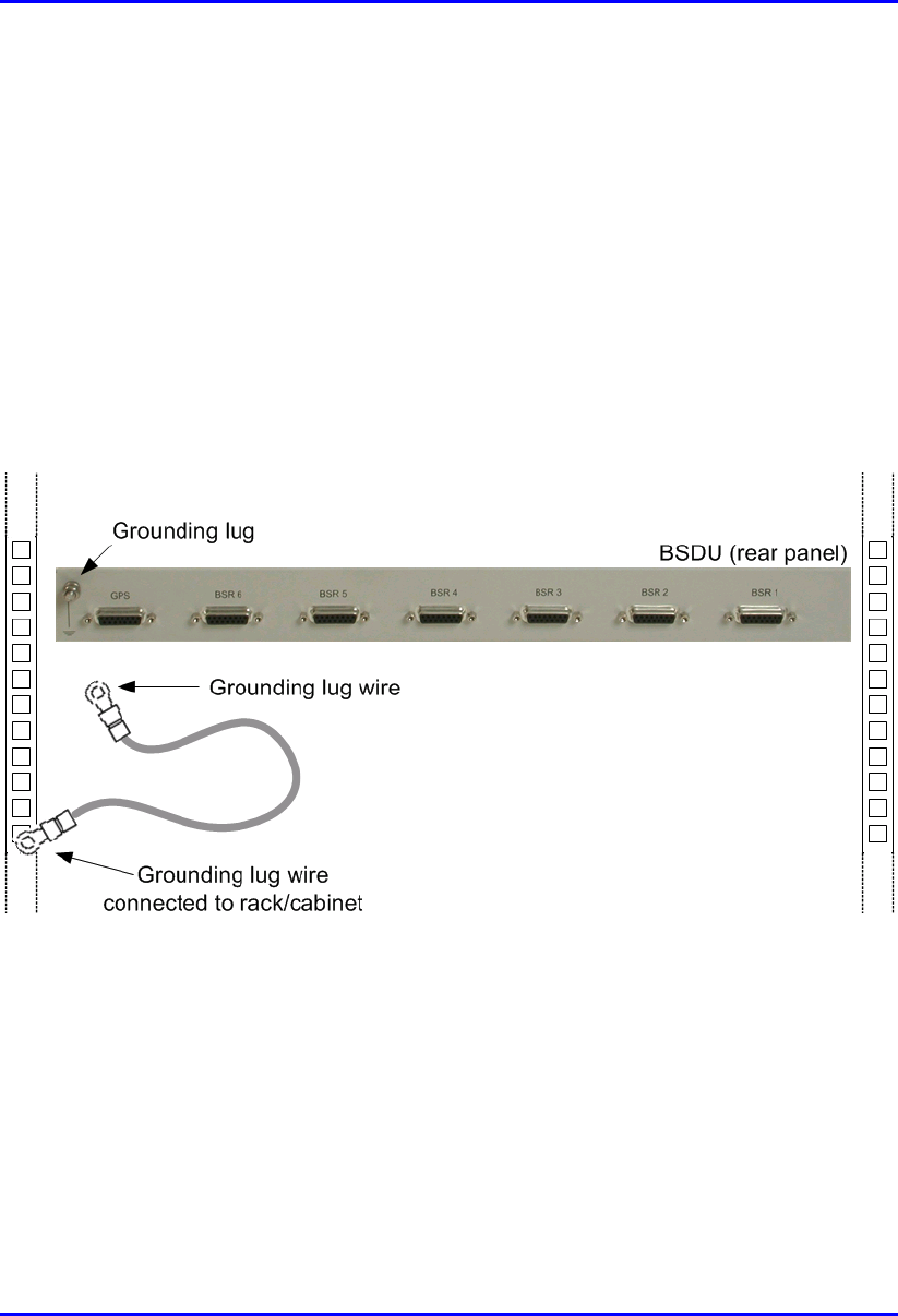
5.12.1. Grounding the BSDU
Before connecting the power supply to the BSDU, you need to ground (earth) the
BSDU.
To ground the BSDU:
1. Connect one end of the grounding lug wire (green/yellow) to the grounding lug
screw located on the rear panel of the BSDU chassis (see Figure 5-11).
2. Connect the other end of the grounding wire to the cabinet rack or any other
customer grounded point at the base station.
Figure 5-11: BSDU grounding connection (BSDU rear panel)
Hardware Installation Guide Installing the BSDU
02030311-05 Airspan Networks Ltd. 5-23
5.12.2. Connecting to Power Supply (BSPS)
The connection between the BSDU and the power supply unit (BSPS) is made via a
two-meter long DC shielded power cable (supplied). The power cable has a power
connector at each end of the cable and a wire for preventing cable disturbances and
radiation. The power cable is connected to the BSDU’s power connector.
The wire color-coding is as follows:
! Red: positive
! Black: negative
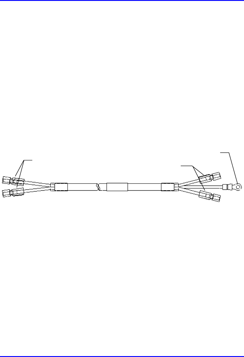
Figure 5-12 displays the power cable with the power connectors on each side and the
grounding lug wire on the side that connects to the BSDU.
Figure 5-12: Power cable (with ground wire) for connecting BSDU to BSPS
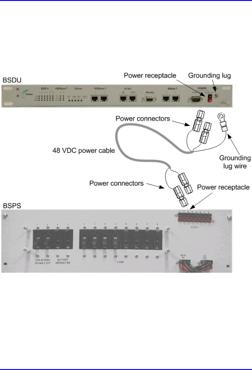
To connect the BSDU to the power supply unit (see Figure 5-13):
1. Connect the cable’s power connectors on the cable side that provides an
additional wire for preventing power radiation, to the BSDU’s power port
labeled POWER -48 VDC. Ensure that the black-colored (i.e., negative) side of
the connector is inserted in the upper part of the power receptacle; and the red-
colored (i.e., positive) side of the connector is inserted in the lower part of the
power receptacle (see Figure 5-13).
2. Connect the grounding lug wire for radiation immunity, to the BSDU’s
grounding lug screw, located alongside the BSDU’s power receptacle (see
Figure).
Grounding lug wire
Power connectors
for BSDU
Power connectors
for BSPS
Installing the BSDU Hardware Installation Guide
5-24 Airspan Networks Ltd. 02030311-05
3. Connect the other end of the power cable to the power source (i.e., to the
customer’s power supply or to the WipLL BSPS). Ensure that the black-colored
(i.e., negative) side of the connector is inserted in the upper part of the power
receptacle; and the red-colored (i.e., positive) side of the connector is inserted in
the lower part of the power receptacle (see Figure 5-13).
Figure 5-13: BSDU-to-BSPS power cable connections
Hardware Installation Guide Installing the BSDU
02030311-05 Airspan Networks Ltd. 5-25
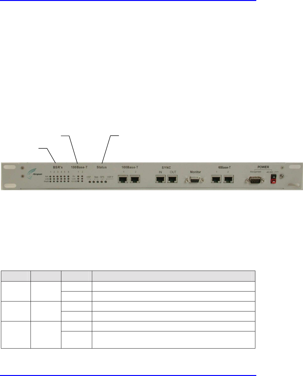
5.13. LED Indicators
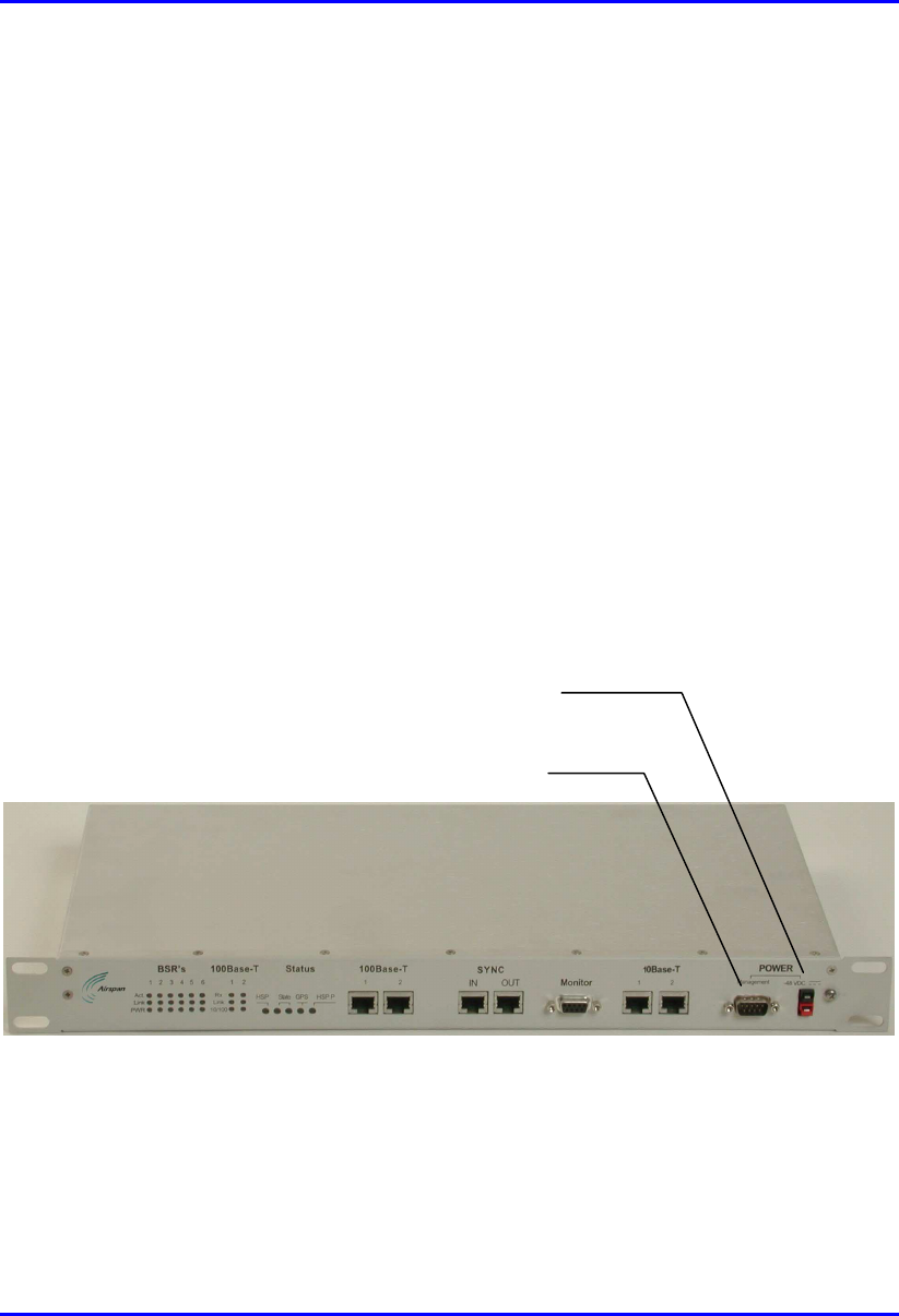
The BSDU provides various LED indicators located on the BSDU’s front panel (see
Figure 5-14). These LEDs are grouped as follows:
! BSR’s LEDs
! 100Base-T LEDs
! Status LEDs
Figure 5-14: BSDU LED indicators
5.13.1. BSR’s LEDs
The BSDU’s BSR’s LED indicators, located on the BSDU’s front panel, includes
three LEDs for each of the six BSR ports. These LEDs are described in Table 5-3.
Table 5-3: BSR’s LED Description
LED Color Status Meaning
On Ethernet activity is detected on the BSR port
Act Yellow
Off No Ethernet activity is detected on the BSR port
On Physical link exists between the BSDU and BSR
Link Yellow
Off No physical link exists between the BSDU and BSR
On Power is supplied to the BSDU’s BSR port
PWR Yellow
Off The BSDU’s BSR port is disabled by software, or port failure
has occurred
BSR’s LEDs
100Base-T LEDs Status LEDs

Installing the BSDU Hardware Installation Guide
5-26 Airspan Networks Ltd. 02030311-05
5.13.2. 100Base-T LEDs
The BSDU’s 100Base-T LED indicators, located on the BSDU’s front panel,
includes three LEDs for each of the two 100Base-T ports. These LEDs are described
in Table 5-4.
Table 5-4: 100Base-T LED Description
LED Color Status Meaning
On Data is received through the 100Base-T port
Rx Yellow
Off No data is received through the 100Base-T port
On Viable physical link between the 100Base-T port and the
external device to which this port connects
Link Yellow
Off No physical link between the 100Base-T port and the external
device to which this port connects
On Power is supplied to the 100Base-T port
10/100 Yellow
Off No power at the 100Base-T port
Hardware Installation Guide Installing the BSDU
02030311-05 Airspan Networks Ltd. 5-27
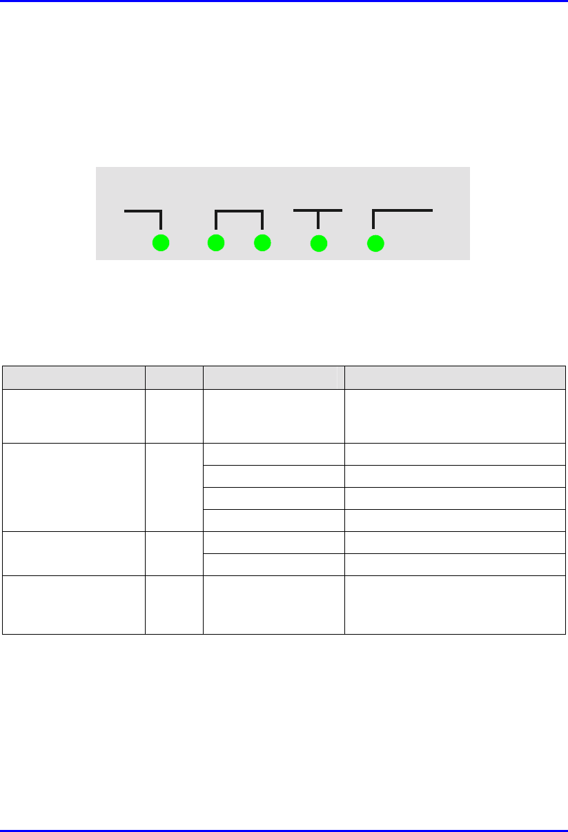
5.13.3. Status LEDs
The BSDU’s Status LED indicators, located on the BSDU’s front panel, are
displayed in Figure 5-15.
HSP State GPS HSP P
Figure 5-15: BSDU Status LEDs
The Status LEDs are described in Table 5-5.
Table 5-5: Status LED Description
LED Color Status Meaning
HSP (Hop
Synchronization
Process)
Green On BSDU synchronization process is
active
Only right LED is on Synchronization process is starting
Both LEDs are on BSDU is the master unit
Only left LED is on BSDU is a slave unit
State (two LEDs) Green
Both LEDs are off BSDU sync pulse lost
On GPS is connected to the BSDU
GPS (Global
Positioning Satellite)
Green
Blinking Receiving a satellite signal
HSP P (Hop
Synchronization
Process Pulse)
Green On Change state for the HSP pulse
02030311-05 Airspan Networks Ltd. 6-1
Installing the GPS
Installing the GPSInstalling the GPS
Installing the GPS
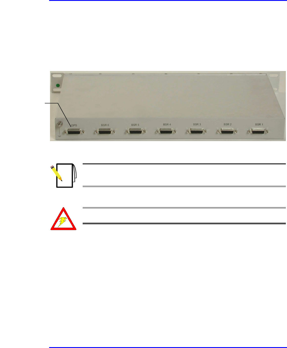
The WipLL system provides BSDU connectivity to GPS antennas for synchronizing
multiple base stations and avoiding radio frequency ghosting effects. The GPS
antenna ensures that the entire WipLL network operates with the same clock, based
on a universal satellite clock signal.
Figure 6-1: GPS antenna for clock synchronization
6

Installing the GPS Hardware Installation Guide
6-2 Airspan Networks Ltd. 02030311-05
6.1. Mounting the GPS
Depending on individual customer requirements and environmental influences there
are several available options for mounting the GPS:
! Pole Mounting:
The GPS may be mounted to a pole similar to that used to mount the BSR (See
Chapter 4, “Installing the BSR”).
! Mounting Plate:
The GPS may be mounted to a wall or roof top structure using a purpose-made
mounting plate supplied with the unit.
! Direct Mounting:
The unit may be mounted directly to a suitable structure that has been provided
with holes suited to the GPS mounting details.
! Magnetic Mounting:
An optional magnetic mounting device is available to allow GPS mounting to a
suitable surface, e.g., vehicle roof or steel building structure. This device is
attached by means of the threaded holes provided in the base of the GPS.
Hardware Installation Guide Installing the GPS
02030311-05 Airspan Networks Ltd. 6-3
6.2. Connecting to the BSDU
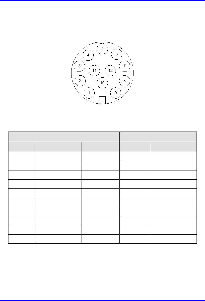
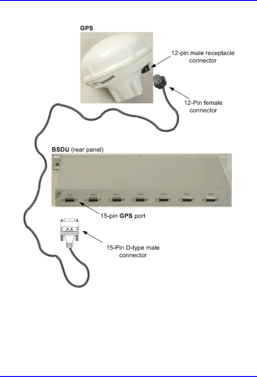
The GPS antenna is connected to the BSDU’s 15-Pin D-type port, labeled GPS (see
Figure 6-2).
Figure 6-2: BSDU rear panel showing GPS port
Note: Airspan supplies un-terminated cables for connecting the GPS to the
BSDU. Refer to Appendix B, “Cable Crimping" for cable crimping procedures
for these connectors.
Warning: To avoid electrical or fire hazard, ensure that the connection to the
GPS is made prior to connecting the BSDU to the power supply.
The following describes the cables and connectors:
! Connector:
! GPS: 12-pin female (Deutsch MMP26C-2212S1)
! BSDU: 15-Pin D-type male
! Cable: Multipair Overall Shielded (22 AWG)
15-Pin D-type
p
ort for GPS
Installing the GPS Hardware Installation Guide
6-4 Airspan Networks Ltd. 02030311-05
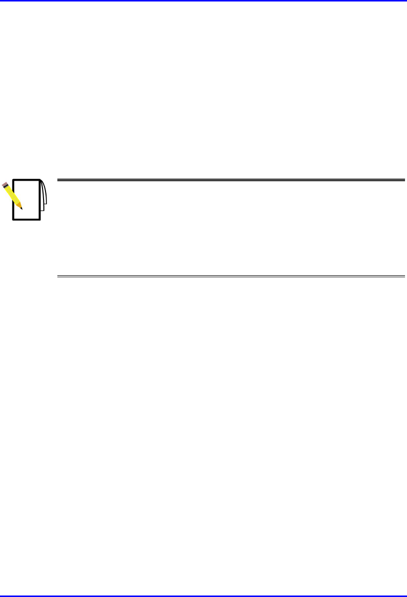
! Connector pinouts: The GPS connector receptacle contains 12 male contacts, as
displayed in Figure 6-3.
Figure 6-3: GPS connector pinouts
The connector pinouts for the GPS and BSDU are described in the following table.
12-pin female (GPS) 15-pin D-type male (BSDU)
Pin Pin name Cable color Pin Lead
1 POWER Red 9
2 RX_DATA_1-
Blue 5 TD+ (after R5)
3 RX_DATA_1+
Black 6 TD-
4 TX_DATA_1-
Yellow 4 RD-
5 TX_DATA_1+
Black 3 RD+ (after R3)
6 RX_DATA_2-
Brown x
7 RX_DATA_2+
Black x
9 GND Black 10
11 1PPS+ Green 8 1PPS-
12 1PPS- Black 7 1PPS+ (After R7)
Hardware Installation Guide Installing the GPS
02030311-05 Airspan Networks Ltd. 6-5
To connect the GPS antenna to the BSDU:
1. Connect the 12-pin female connector, at the one end of the cable, to the 12-pin
receptacle connector located at the underside of the GPS.
2. Connect the 15-pin D-type male connector, at the other end of the cable, to the
15-pin D-type port labeled “GPS” at the rear panel of the BSDU.
Figure 6-4 illustrates the BSDU-to-GPS cable connections.
Note:
- When installing the cable, secure the cable to the mounting pole or bracket
with a cable tie to hold the weight of the cable (cable strain relief).
- A loop should be left in the dressed cable for maintenance purposes and to
prevent the cable weight being taken directly on the connector itself.
- Ensure that the connector is waterproof.
Installing the GPS Hardware Installation Guide
6-6 Airspan Networks Ltd. 02030311-05
Figure 6-4: BSDU-to-GPS cable connections

02030311-05 Airspan Networks Ltd. 7-1
Installing the BSPS
Installing the BSPSInstalling the BSPS
Installing the BSPS
This chapter describes the installation of the WipLL Base Station Power Supply
unit (BSPS), which is installed at the base station.
This chapter includes the following sections:
! Overview
! BSPS Components
! General Site Requirements
! BSPS Cabinet Cabling
! BSPS Installation Summary
! Installing BSPS Batteries
! Rectifiers
! Installing
! Calibrating
! Operating the System Controller
! Connecting BSPS Power to BSDUs
! Connecting the BSPS Management Cables
! BSPS Cabinet Power Requirements
! BSPS Cabinet Grounding
! BSPS Equipment Supplementary Grounding
! BSPS Troubleshooting
7
Installing the BSPS Hardware Installation Guide
7-2 Airspan Networks Ltd. 02030311-05
7.1. Overview
The WipLL Base Station Power Supply unit (BSPS) is an optional WipLL unit that
provides power (and power redundancy) to the BSDU/BSR if no –48 VDC power
supply exists at the base station.
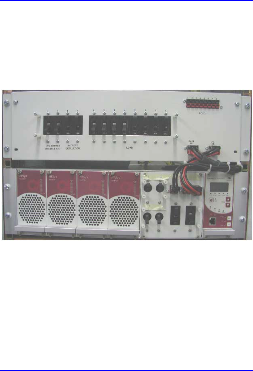
The BSPS front panel is displayed in Figure 7-1.
Figure 7-1: BSPS front panel
The BSPS provides the BSDUs/BSRs with the following:
! Power supply of –48 VDC
! Power redundancy in case of power failure. The BSPS charges a battery bank
that provides this power redundancy during mains failure. Thus, the BSPS acts
as a DC-UPS with a battery connected to it. The size of the battery determines
the backup and charging time. Since the system is current limited, the maximum
battery size is based on that limit.)

Hardware Installation Guide Installing the BSPS
02030311-05 Airspan Networks Ltd. 7-3
! Remote management and monitoring through WipLL’s WipManage or
WipConfig management application.
The BSPS is delivered pre-installed in an Airspan cabinet. The only installation that
is required includes the following:
! Installing the BSPS battery
! Connecting the BSPS temperature sensor to measure battery temperature
! Connecting the BSPS to the BSDU
7.1.1. BSPS Components
The BSPS consists of the following basic components:
! DC Rectifier modules: The Rectifier converts the AC current to DC. The BSPS
can house up to four rectifiers. The rectifiers are “hot plugged” and operate in
parallel. This enables the user to define an “N+1”or “N+2”redundant system.
Each rectifier has its own current sharing system, satisfying a complete sharing
among rectifiers.
! System controller: provides BSPS management control and BSPS operating
information
! Electronic Low Voltage Detector (ELVD): disconnects the battery from the
load, avoiding damage to the battery when over-discharged.
! Battery: provides the BSPS system with back-up power
! Load and battery circuit breakers for DC protection and distribution
! DC Distribution unit: provides circuit breakers for distributing the output
current to multiple BSDUs.
The unit also contains a bypass switch to bypass the LVD.
Note: For power redundancy, at least two rectifiers must be installed.
Installing the BSPS Hardware Installation Guide
7-4 Airspan Networks Ltd. 02030311-05
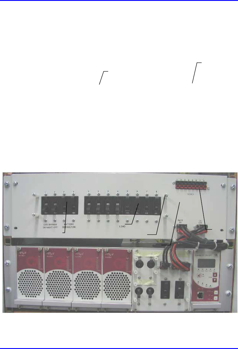
The main power rack is housed in a 19” (inches) front mountable chassis.
Figure 7-2 displays the BSPS main components.
System Controller
Line Breaker
Battery Breaker
Load Breaker
Rectifier module
DC Distribution module
Power ports for connection
to BSDUs
Figure 7-2: BSPS Main Rack front view
Hardware Installation Guide Installing the BSPS
02030311-05 Airspan Networks Ltd. 7-5
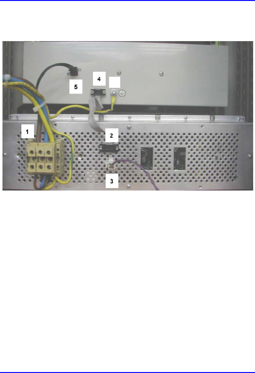
Figure 7-3 displays the rear panel of the main BSPS rack.
6
Figure 7-3: BSPS Main Rack rear view
1. AC connection
2. Comm to DC Distribution
3. Temperature Sensor
4. Comm to power system
5. LVD connection
6. Ground

Installing the BSPS Hardware Installation Guide
7-6 Airspan Networks Ltd. 02030311-05
7.1.2. General Site Requirements
Note: Cable sizes and electrical circuit protection devices discussed in the
following section are typical for 230 Volt AC circuits only. Adjustments are
required for applications other than this.
During AC power installation activities at base station premises the following
general requirements should be adhered to:
! The customer must provide a valid safety certificate for the electrical circuit to
which the equipment is to be connected. If this documentation is not available
checks must be carried out in accordance with local electrical installation test
requirements.
! A qualified electrician must carry out the provision of any additional power
outlets.
! Cables used in the customer premises electrical circuit are to be 3-core 6mm2.
Color-coding for live neutral and earth conductors shall be in accordance with
local electrical regulations.
! The base station premises AC distribution panel must be capable of supplying up
to 240 Volts AC.
! The customer is to allocate and clearly identify fuses in AC distribution panel
that will provide protection for equipment in BSPS cabinet. The circuit is to be
protected by a 32 amp protective device in accordance with local standards.
! The customer shall provide a wall mounted AC power socket adjacent to the
BSPS cabinet. Local territory equipment isolation and earth leakage
requirements are to be met when selecting the plug and socket type.
Alternatively a 32-amp isolator switch may be used for connection to the mains
power supply.
! A common earth point (CEP) shall be designated in the customers’ base station
premises to which the system cabinet earth will be connected.
! A minimum separation distance of 200 mm is to be maintained between AC and
DC signaling cables when they run parallel to each other. However these cables
may cross each other at right angles.

Hardware Installation Guide Installing the BSPS
02030311-05 Airspan Networks Ltd. 7-7
7.1.3. BSPS Cabinet Cabling
This section defines the procedures to be adhered to when installing data cables in
the BSPS cabinet.
Note: A minimum separation of 200 mm should exist between power and data
cables.
! Cable access apertures are located in the top surface of the cabinet. Separate
apertures are provided for power and data cables. All cabling entering and
exiting the BSPS cabinet shall be protected using flexible conduit and gland
systems suited to the cabinet. Power and data cables should exit from the BSPS
cabinet via separate apertures.
! Data cables are to be secured to cable guides provided on the left-hand side of
the cabinet when viewed from the rear. Cables are to be brought together to a
point on the cable guide from where they can be fanned out and fed to the Base
station Distribution Units (BSDU’s).
! Data cables terminating at the front of the BSDU’s should be fed through the
brush gland fitted adjacent to the units and secured to the cable management bar
using tie-wraps.
! When cabling the BSPS cabinet consideration should be given to future growth
and expansion. Allowances in cable forms should be made for the removal of
equipment for maintenance, i.e., BSDU’s, Power racks etc.
! Where cables are installed but not connected to equipment they should be tied
off in such a way as to prevent damage, allow for future growth and
maintenance. Pre-terminated cables should be treated with care and should not
be laid out in vulnerable areas where they may be susceptible to damage.
! Cable crossovers should be kept to a minimum to prevent system interference
and allow easy equipment removal.
! Ensure that the cables are dressed in such a fashion that they are not exposed to
hot exhaust air, sharp edges, doors etc.

Installing the BSPS Hardware Installation Guide
7-8 Airspan Networks Ltd. 02030311-05
! Observe recommended minimum bend radii when installing copper cables.
Wherever a cable changes direction, ensure that it does so in a smooth curve
with a radius of at least 50mm in order to prevent damage.
! Cables shall be secured directly to cabinet cable trays with plastic cable ties.
Secure the data and power cables at regular intervals within the cabinet to the
cable management trays/trunking provided using cable ties. These ties should be
tensioned and cut using the supplied tool 1PAC10370ACK.
! Care is to be taken to ensure that cables providing connection to peripheral
equipment (e.g. PC’s) do not pose a trip hazard.
! WipLL system interface cables providing connection to a network shall be
terminated and presented to a digital distribution frame (DDF) as agreed with the
customer. Dressing of cables at the DDF shall be done to ensure a potential trip
hazard is not created.
! All data cables should be labeled with both the source and destination at each
end. Un-used cable ends must also be identified with labels to assist with future
upgrades.

Hardware Installation Guide Installing the BSPS
02030311-05 Airspan Networks Ltd. 7-9
7.2. BSPS Installation Summary
The following is a summary of the procedural steps for installing the BSPS:
1. Verify that the circuit breakers of the load, battery and line input are
disconnected and the system is not connected to the line.
2. Connect the main unit to the battery and load via the Battery and Load terminals
on the rear panel.
3. Connect (if needed) the Extension and DC Distribution units. Pay special
attention to the polarities of the wires and locations.
4. Insert a rectifier module into the main unit. All compartments are similar and
connected in parallel.
5. Use 16mm2 (5 AWG) wires for the AC terminals. Minimum requirement is
8mm2 (8 AWG)
6. AC source must be current limited (50A) using an external circuit breaker.
7. Plug the AC input cord into the AC source.
8. Turn on the Line circuit breaker, and verify that the system controller is
activated.
9. Insert the other rectifiers, and verify all green LED's on the panels are lit.
10. All parameters such as the output voltage are pre-defined in the factory.
11. Connect the temperature sensors to the appropriate connector at the rear panel of
the main unit. Place the sensors in the battery compartment.
12. Switch on the LOAD and BATTERY circuit breakers. Verify that the BYPASS
breakers are off.
The system is now ready for use.
13. Verify that the FAULT red LED is not lit and the buzzer not active.
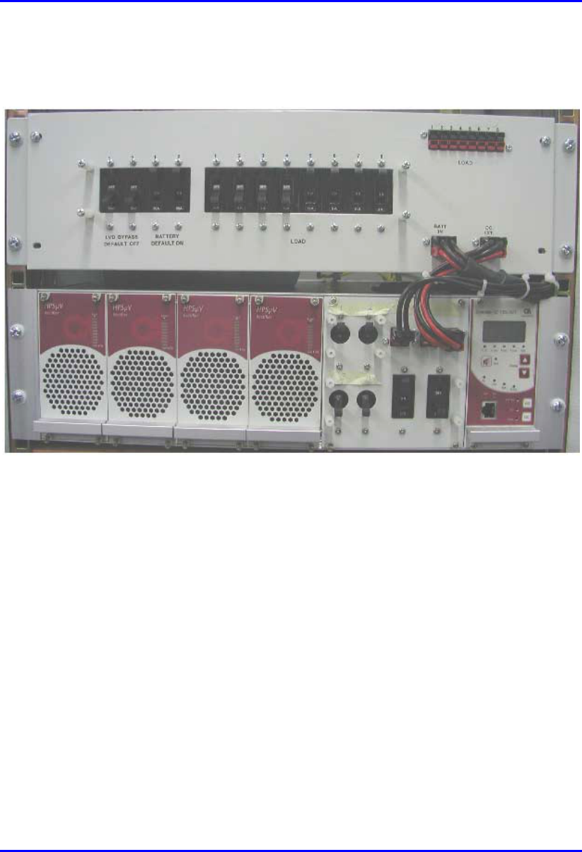
Installing the BSPS Hardware Installation Guide
7-10 Airspan Networks Ltd. 02030311-05
14. Connect a PC to the RJ-45 port at the front panel of the main unit to control the
system (optional).
Figure 7-4: BSPS Main Rack front view
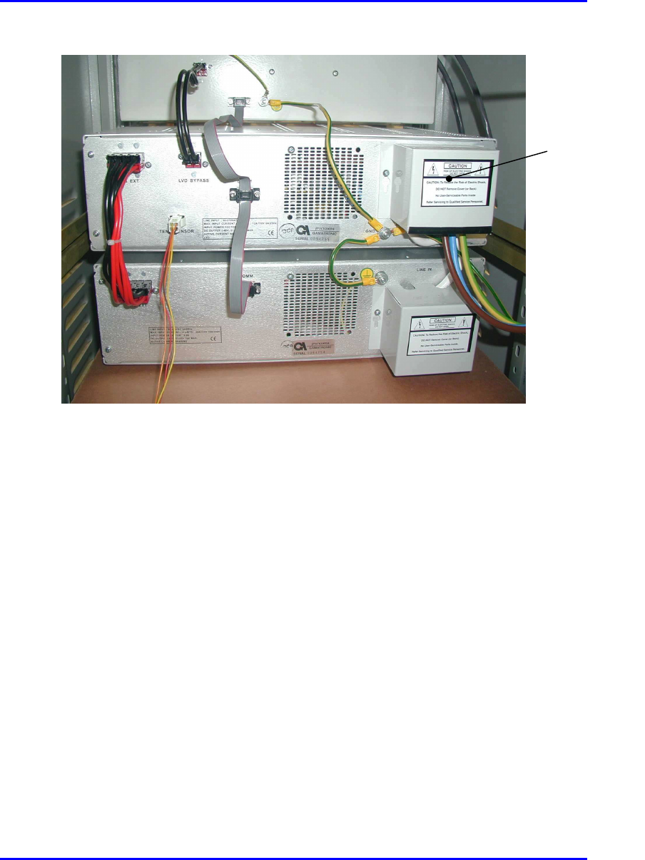
Hardware Installation Guide Installing the BSPS
02030311-05 Airspan Networks Ltd. 7-11
Figure 7-5: Rear BSPS cable connections
Protective
covers

Installing the BSPS Hardware Installation Guide
7-12 Airspan Networks Ltd. 02030311-05
7.3. Installing BSPS Batteries
To provide the BSPS system with back-up power, two battery circuits are provided.
Batteries are located on two shelves fitted in the lower sections of the system
cabinet.
A battery protection tray is to be fitted beneath the BSPS racks to prevent tools from
falling onto batteries below.
Warnings:
1) Final battery connection, at the DC distribution rack, must only be made
once the battery is fully installed.
2) The Airspan insulated torque wrench 1PAC10383 AAD must be used when
attaching battery terminations. The wrench is pre-set to ‘break’ at 5.5 Nm
(Newton-meters).
3) Caution must be observed when fitting and connecting batteries as to
prevent the shorting of connections to the cabinet structure.
Insulated tools and the removal of jewellery are mandatory in all live power
installations.
To install the BSPS battery:
1. Prior to installation use a digital multimeter (DMM) to measure the voltage
output from each monobloc. A reading of 12.3 Volts DC is required from each
monobloc.
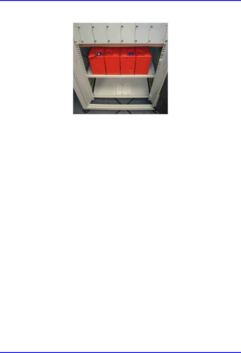
2. Install the monoblocs onto the battery trays as shown in Figure 7-6.
Hardware Installation Guide Installing the BSPS
02030311-05 Airspan Networks Ltd. 7-13
Figure 7-6: Cabinet battery area
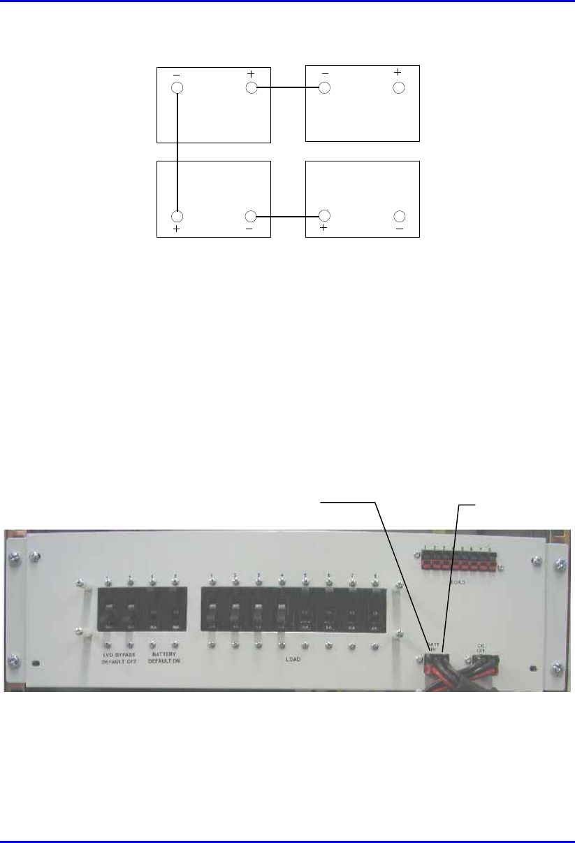
Up to four monoblocs can be housed on each shelf. Connections between the
monoblocs are as illustrated in Figure 7-7.
3. Connect a short battery strap between monoblocs 1 and 2.
4. Using an insulated spanner/wrench tighten the battery terminal nut to the torque
setting recommended by the manufacturer.
5. Using a digital multimeter check across the positive and negative terminals of
the connected monoblocs and ensure that a voltage of 24 VDC is present.
6. Repeat the above steps for the connections between monoblocs 3 and 4.
7. Connect a long battery strap between monoblocs 2 and 3.
8. Using a digital multimeter check across the positive and negative terminals of
monoblocs 1 and 4 and ensure that a voltage of 48 VDC is present.
Installing the BSPS Hardware Installation Guide
7-14 Airspan Networks Ltd. 02030311-05
34
2 1
Figure 7-7: Method of interconnection between monoblocs
9. Protect the terminals of the monoblocs using suitable battery grease.
10. Before connecting the BSPS battery cables to the battery ensure that the battery
isolation circuit breakers are in the OFF position.
11. Connect the red lead of the BSPS battery cables to the positive terminal on
monobloc 4.
12. Connect the black lead of the BSPS battery cable to the negative terminal on
monobloc 1.
Battery 1
connection
Battery 2
connection

Hardware Installation Guide Installing the BSPS
02030311-05 Airspan Networks Ltd. 7-15
13. Check the voltage across the terminals battery input plug DC distribution rack
using a DMM. Ensure that a reading of 48 volts DC is present. If so insert the
plug into the corresponding socket on the front of the DC distribution rack.
14. Repeat the above steps for battery 2 if required.
Note: If any faulty readings were recorded during the process, this would
indicate a damaged monobloc or battery strap. Investigate and replace the
faulty component.
7.4. Rectifiers
The Rectifier module is the heart of the Full-Redundancy 48 VDC BSPS power
system. It converts the input AC to DC current. The Rectifier is a plugged-in module
designed specifically for modular systems. The BSPS can house up to three basic
rectifiers
7.4.1. Installing
The following provides a step-by-step procedure for installing a rectifier.
To install a rectifier in the BSPS system:
1. Remove the blank panel from where you want to install an additional rectifier in
the rectifier shelf.
2. Insert the rectifier into its place with the upper and lower slides.
3. Secure the rectifier in place with 4 screws in the front panel.
4. Verify that the ON LED is lit.
5. If there is a load on the BSPS system, verify, via the Load Bar, that there is
current sharing in the BSPS system by the rectifier.
Installing the BSPS Hardware Installation Guide
7-16 Airspan Networks Ltd. 02030311-05
7.4.2. Calibrating
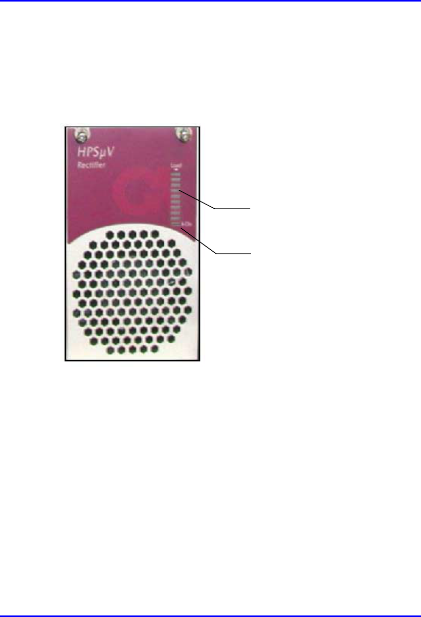
The output current indication is indicated by an LED bar graph shown on the unit
front panel. This bar graph is used to verify current sharing operation between
modules fitted in the rack, and to indicate the percentage of the full load.
On LED indicator
Bar graph
Figure 7-8: Rectifier module front view
The calibration of the Rectifier module is simple and involves a single trimmer-
potentiometer that adjusts the output voltage.

Hardware Installation Guide Installing the BSPS
02030311-05 Airspan Networks Ltd. 7-17
To calibrate the rectifier:
1. Remove the rectifier from the unit.
2. Connect the Share (+) bus to the negative pole (-) of the rectifier.
3. Using a DMM set the output voltage to 53.50 VDC.
4. Check the single rectifier using a female connector (such as the one used in the
units of the system).
Or
5. Perform provisions for the calibration on a dedicated unit.
6. Access the trimmer via the small opening at the back of the cover.
Installing the BSPS Hardware Installation Guide
7-18 Airspan Networks Ltd. 02030311-05
7.5. Operating the System Controller
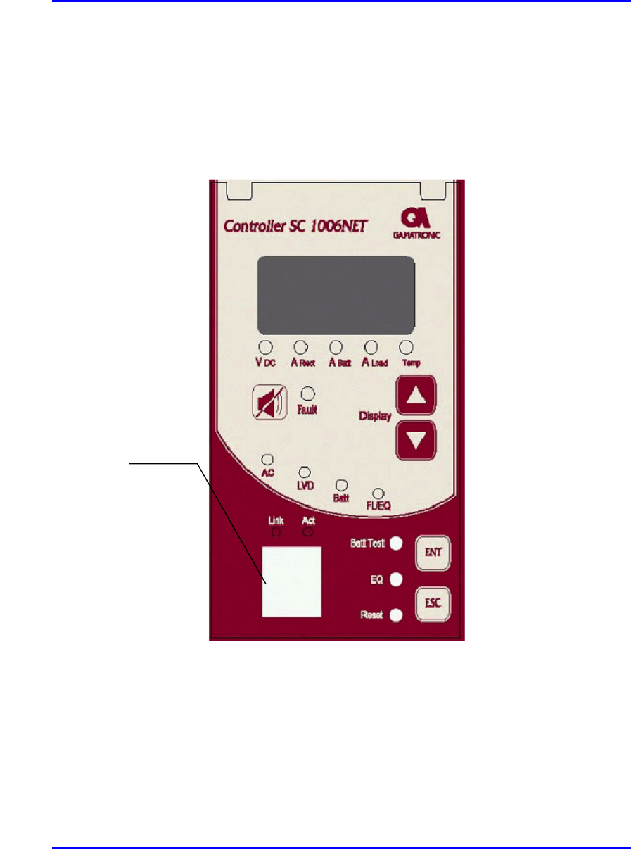
Figure 7-9 shows the features provided on the front panel of the system controller
module.
Figure 7-9: System controller front panel
8-pin RJ-45 port

Hardware Installation Guide Installing the BSPS
02030311-05 Airspan Networks Ltd. 7-19
The function of the LED’s provided on the System controller module can be defined
as follows:
LED Color Meaning
AC Green Input AC voltage is normal
DC Green Output DC voltage is normal
LVD Red State of the Low Voltage Disconnect circuit: red indicates that
the battery is disconnected
BATT Green Battery test has passed
Red continuous General fault alarm
FAULT
Red blinking Faulty rectifier detected
The following lists the buttons and their functions on the System Controller module.
Button Function
BATT TEST This is a manual battery test button. A pencil tip may be used to activate.
ALARM OFF This button silences the module internal buzzer. A pencil tip may be used to
activate.
RESET This button resets the module. A pencil tip may be used to activate.
Installing the BSPS Hardware Installation Guide
7-20 Airspan Networks Ltd. 02030311-05
7.6. Connecting BSPS Power to BSDUs
The BSPS’s DC Distribution unit provides circuit breakers for distributing power
output to BSDUs housed in the WipLL cabinet.
The DC Distribution unit contains a switch that provides an LVD circuit bypass
option. When this switch is activated the battery is no longer protected against deep
discharge and the system controller alarm is then activated.
The distribution rack is provided with front panel and rear panel terminations for
connecting to the BSPS main power rack.
To connect the BSPS DC power supply to the BSDU:
1. Attach the shielded power cable connector (supplied) end that contains the wire
for preventing power radiation, to the BSDU’s power port—labeled POWER -
48 VDC. Ensure that the black-colored (i.e., negative) half of the connector is
positioned at the top and the red-colored (i.e., positive) half at the bottom.
Figure 7-10: BSDU front panel with power port and screw attachment for power
radiation immunity
2. Connect the power cable’s yellow/green lug wire, for radiation immunity, to the
BSDU chassis by using the screw attachment located alongside the power port,
as displayed in Figure 7-10.
Screw for power cable
radiation immunit
y
Power port
Hardware Installation Guide Installing the BSPS
02030311-05 Airspan Networks Ltd. 7-21
3. Connect the other end of the power cable to the DC output port of the BSPS’s
DC Distribution unit (labeled LOAD).
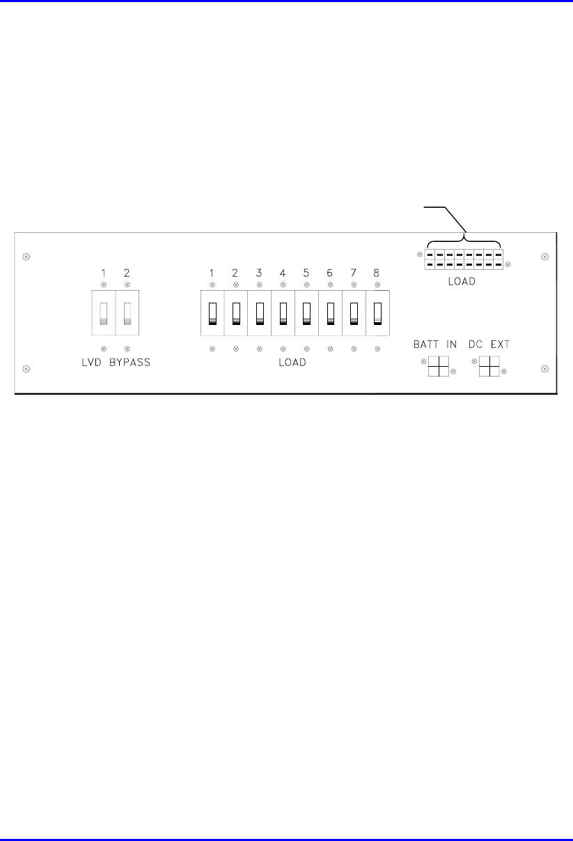
The rack front panel is shown in Figure 7-11.
DC power connections
to BSDUs
Figure 7-11: DC Distribution Rack front view
! LOAD DC—DC connection to BSDUs
! DC EXT—extension rack DC power input connection
! BATT IN—battery input connection
! LVD BYPASS—bypass circuit breakers
! LOAD—load circuit breakers
The rack rear panel is shown in Figure 7-12.

Installing the BSPS Hardware Installation Guide
7-22 Airspan Networks Ltd. 02030311-05
Figure 7-12: DC Distribution Rack rear view
! LVD BYPASS—LVD bypass input connection from main rack
! COMM—Main/Extension Rack Communication port
7.7. Connecting BSPS Management Cables
Connecting the BSPS’s System Controller module to the WipLL BSDU provides the
user with the ability to control the power system operating parameters, retrieving
system data, and status information.
The BSPS System Controller connects to the BSDU(s) via an RJ-45 port located on
the front panel of the controller module. This is connected to BSDU’s 9-Pin D-type
port, labeled POWER Management.
! Connectors:
! BSPS: 8-pin RJ-45 (or for previous BSPS models, a 9-Pin D-type)
! BSDU: 9-pin D-type female
! Connector pinouts:
! BSPS’s 8-Pin RJ-45:
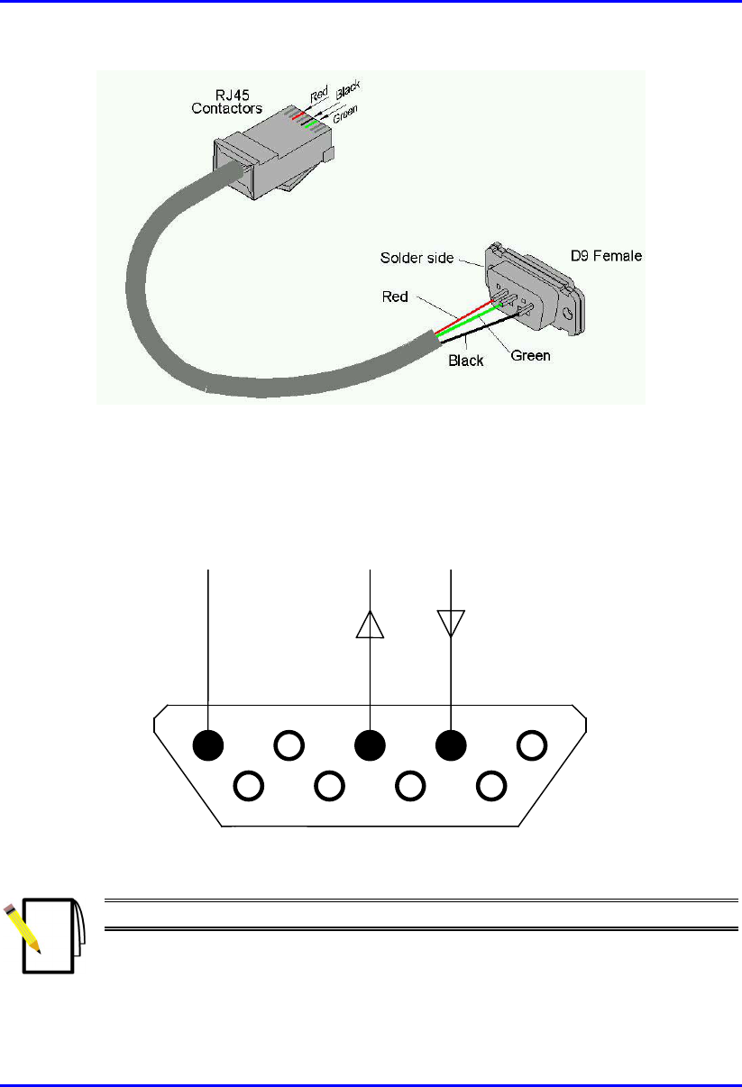
Hardware Installation Guide Installing the BSPS
02030311-05 Airspan Networks Ltd. 7-23
Figure 7-13: BSDU-to-BSPS management connectors via RJ-45 (BSPS) to 9-Pin D-
type (BSDU)
! BSDU’s 9-pin D-type:
1 5
6 9
Rx
Tx
COM
Figure 7-14: BSDU’s 9-pin D-type Connector Pinouts
Note: See Chapter 5, “Installing the BSDU” for detailed connector pinouts.

Installing the BSPS Hardware Installation Guide
7-24 Airspan Networks Ltd. 02030311-05
7.8. BSPS Cabinet Power Requirements
The following section describes the BSPS cabinet mains power requirements.
Warning: The following information assumes a fully populated BSPS cabinet
with main and extension power racks fitted.
Cable sizes and electrical circuit protection devices discussed in the following
section are typical for 230 Volt AC circuits only. Adjustments are required fo
r
other applications.
! Within the BSPS cabinet protected AC mains feeds are required for the main
power rack and two power outlets.
! Both power outlets are to be installed within the cabinet on an independent radial
circuit. Sockets are to be used for the connection of ancillary test/commissioning
equipment only. The type of socket used is dependant on local electrical
requirements.
! Power within the BSPS cabinet is to be distributed from a modular AC consumer
unit fitted with a 100 amp DP isolator. The unit is to be a metal-clad type with
sufficient outputs for services in the cabinet.
! The following tables displays the protective device rating and cable specification
required for each element of the cabinet AC circuit.
Service Fuse Rating Cable Spec
Cabinet power input 32 amp 6 mm2
Main rack input 16 amp 2.5 mm2
Extension rack link N/A 2.5 mm2
Power socket No.1 6 amp 1.5 mm2
Power socket No.2 6 amp 1.5 mm2
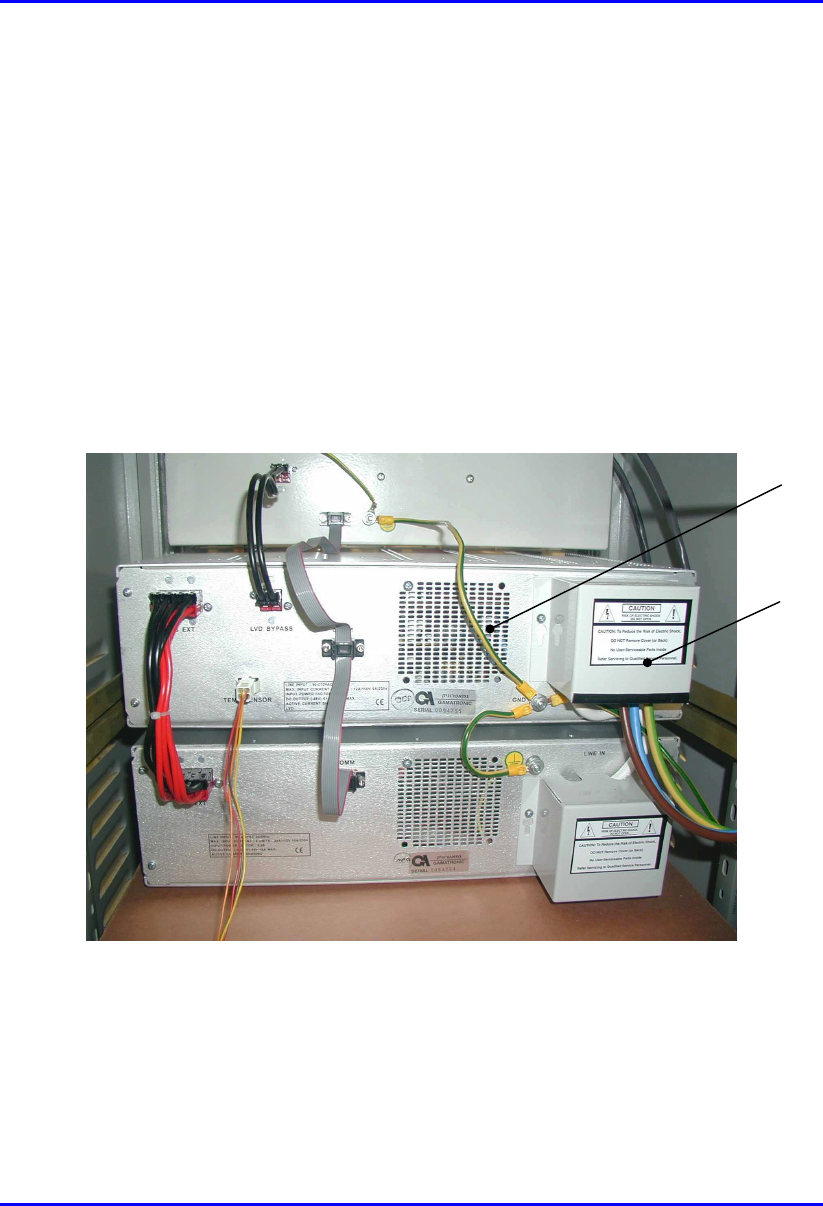
! Provision is made on the rear of the BSPS main power rack for the AC power
connection. A terminal block is provided for the link to the extension power rack
when fitted.
Hardware Installation Guide Installing the BSPS
02030311-05 Airspan Networks Ltd. 7-25
! A terminal block is provided on the rear of the power extension rack for the link
from the main power rack.
! When connecting racks to the AC mains supply loosen the grub screws on the
terminal blocks. Insert the bare copper conductor ensuring correct polarity.
Firmly tighten the screw and gently pull on each cable to ensure the grub screw
has made full contact. Ensure that bare wires are not exposed.
! The plug fitted to the BSPS cabinet power input cable is to be compatible with
the socket provided in the customers’ premises. It must comply with local
regulations for connection of products with earth leakage exceeding 3.5 mA.
! Once AC power connections to the power racks are completed fit protective
covers over the terminal blocks as shown in Figure 7-15.
Figure 7-15: Fitting protective covers over terminal block
! Power cables are to be routed in the cable guide down right-hand side of the
BSPS cabinet (when viewed from the rear).
! Secure cables in position using strategically located cable ties.
Protective
cover
Supplementary
earth
connection

Installing the BSPS Hardware Installation Guide
7-26 Airspan Networks Ltd. 02030311-05
! Power cables external to the BSPS cabinet must be housed in trunking. The
trunking is to be secured to the wall of the equipment room. Type, securing
method and route of trunking is to be in accordance with customers’
requirements.
! A minimum separation distance of 200 mm is to be maintained between AC and
DC/signaling cables when they run parallel to each other. However these cables
may cross each other at right angles.
! Any dust/debris created during the installation of electrical equipment or cables
shall be cleared and correctly disposed of as the installation progresses.
7.8.1. BSPS Cabinet Grounding
Warning: The WipLL BSPS cabinet must be connected to the customers
building common earth point (CEP) earth before connecting AC power supplies
and installing any equipment.
! When the BSPS cabinet has been located an earth cable shall be run from the
building common earth point (CEP) to the primary earth stud of the cabinet.
! Earth cable specification is to be 6mm2. Cable color-coding is to comply with
local regulations.
! Crimp M6 x 6mm2 lug to the end of the cable to be attached to the CEP with
crimp tool ‘BMR 16U3’ (Airspan Code 1PAC10336AED).
! The required length of cable is to be measured back to the cabinet earthing stud
and the excess removed.
! Crimp M6 x 6mm2 lug to the cable end to be attached to the cabinet earth stud
using crimp tool ‘BMR 16U3’ (Airspan Code 1PAC10336AED).
! Attach the earth cable to the CEP using fastenings provided.
! Attach the earth cable to the cabinet primary earth stud using the fastenings
provided.

Hardware Installation Guide Installing the BSPS
02030311-05 Airspan Networks Ltd. 7-27
7.8.2. BSPS Equipment Supplementary Grounding
! Equipment housed in the BSPS cabinet must be supplementary grounded by
connecting a ground lead between each unit ground stud and the cabinet primary
ground stud.
! Cable specification is to be 2.5 mm2. Cable color-coding is to comply with local
regulations.
7.9. BSPS Troubleshooting
The table below indicates methods of solving problems that may arise during the
BSPS installation process.
Table 7-1: BSPS troubleshooting
Symptom Possible Cause Remedy
FAULT LED is
blinking
One or more rectifier modules
are faulty
Replace the faulty rectifier/s
FAULT LED is on
• Any breaker is left open
• Abnormal input or output
voltages
• Over temperature
• LVD is open
• Battery test failed
• Check all breakers
• Check line voltage and load,
rectifiers may be over-loaded
• Check the temperature sensor
• Check the line, general check
• Check the battery breaker, cables
and replace battery if none of this
helps
No backup time
when AC is absent
Battery is not connected
Battery is discharged or power
is low.
Check battery charge, connections
and circuit breaker
Load is not operating Load is not connected • Check load cables.
• Check load circuit breaker.
No current sharing
among rectifiers
(more then 2
segments difference
between any two
• Load is too high.
• Extension rack is not
properly connected to the
main rack.
• Decrease the load or add rectifiers
to the system.
• Check connections.