Airspan Networks AIRSPAN-BSR900 Base Station Radio (BSR) User Manual Part 2A
Airspan Networks Inc Base Station Radio (BSR) Users Manual Part 2A
Contents
- 1. Users Manual Part 1
- 2. Users Manual Part 2A
- 3. Users Manual Part 2B
- 4. Users Manual Part 3
Users Manual Part 2A
02030311-05 Airspan Networks Ltd. 3-1
Part List and Required Tools
Part List and Required ToolsPart List and Required Tools
Part List and Required Tools
This chapter discusse the following:
! Unpacking and veifying contents
! Required tools
3.1. Unpacking and Verifying Contents
Warning: Examine the WipLL shipping container. If you notice any damage,
or missing items, immediately notify the carrier that delivered the unit and
contact the Airspan representative.
The WipLL hardware equipment can be divided into two parts:
! Base station equipment
! CPE equipment
3.1.1. Base Station Equipment
Certain base station equipment is required while others are optional equipment,
depending on the type of configuration and includes the following:
! Base Station Radio (BSR)—required
! Base Station Distribution Unit (BSDU)—optional
! Base Station Power System (BSPS)—optional
! GPS antenna—optional
3
Part List and Required Tools Hardware Installation Gקגןו
3-2 Airspan Networks Ltd. 02030311-05
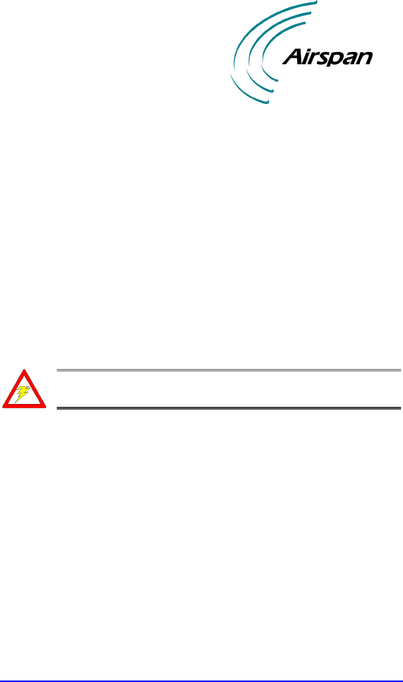
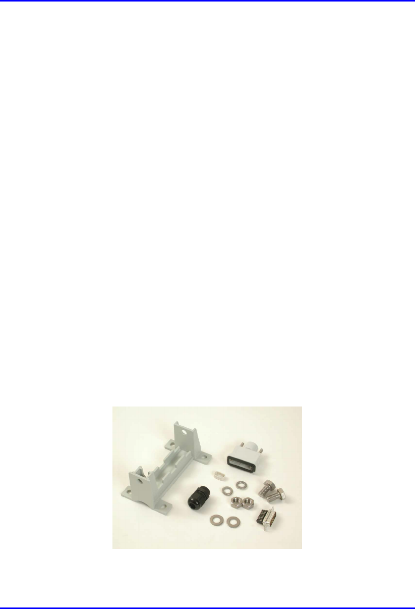
3.1.1.1. BSR
The BSR kit includes the following components:
! BSR chassis
! Mounting equipment that includes:
! Mounting brackets
! Mounting screws:
− Washers
− 4 x screws
− Bolts
! Connectors:
! 15-Pin D-type (for data and serial interface, and power)
! N-type (optional for third-party external antenna)
Figure 3-1: BSR kit
Hardware Installation Gקגןו Part List and Required Tools
02030311-05 Airspan Networks Ltd. 3-3
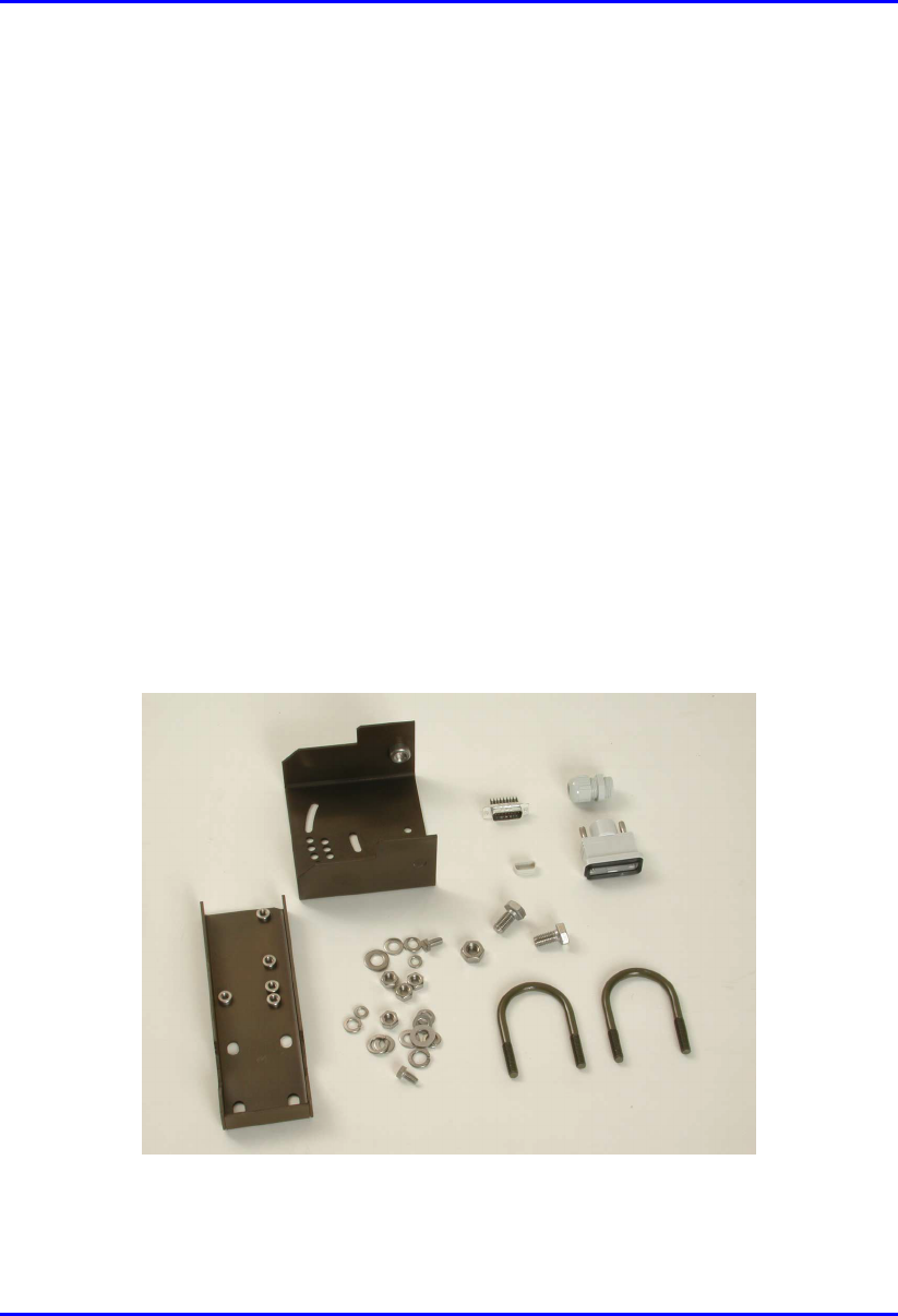
3.1.1.2. BSDU (optional)
The BSDU interfaces between the BSR and the backhaul network, as well as used
for daisy-chaining BSR units. The BSDU kit includes the following connectors:
! Mounting: four off M5 screws and plastic-cup washers
! 6 x RJ-45: two each for 100Base-T, 10Base-T, and clock synchronization
! 2 X 9-Pin D-type (for monitor and management)
! 7 x 15-Pin D-type (for power, Ethernet, daisy-chaining BSRs, and GPS)
! Power cable
Figure 3-2: BSDU kit
Part List and Required Tools Hardware Installation Gקגןו
3-4 Airspan Networks Ltd. 02030311-05
3.1.1.3. BSPS (optional)
The BSPS is an optional power redundancy unit (DC-UPS). The BSPS includes the
following parts:
! Rectifier
! DC Distribution
! System Controller
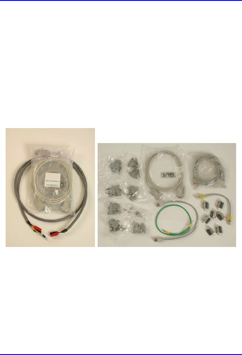
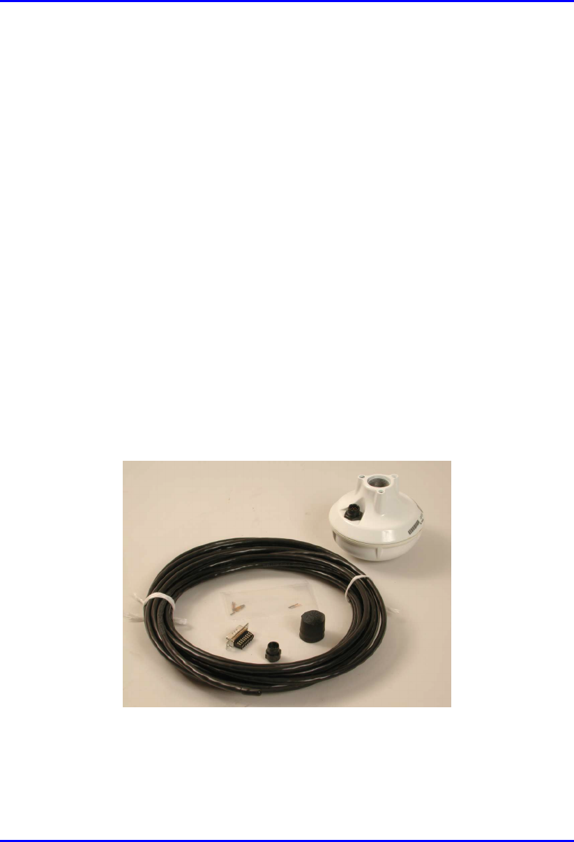
3.1.1.4. GPS (optional)
The GPS antenna synchronizes base stations by providing a universal satellite clock
signal.
! 5,15, or 50 meter mating cable
! 5/8″ adapter
! Magnet mount
Figure 3-3: GPS kit
Hardware Installation Gקגןו Part List and Required Tools
02030311-05 Airspan Networks Ltd. 3-5
3.1.2. Customer Premises Equipment
WipLL hardware installed at the customer’s site includes the following:
! Subscriber Premises Radio (SPR)
! RSSI LED Plug (optional - for measuring SPR’s RSSI levels)
! Subscriber Data Adapter (SDA)
! Indoor Unit (IDR)—optional, instead of the SPR and SDA
3.1.2.1. SPR
The SPR consists of the following parts:
! SPR chassis
! Mounting equipment that includes:
! Mounting bracket
! 2 x Screws
! 2 x Bolts
! 4 x Washers
! 15-Pin D-type connector
Figure 3-4: SPR kit

Part List and Required Tools Hardware Installation Gקגןו
3-6 Airspan Networks Ltd. 02030311-05
3.1.2.2. RSSI LED Plug
The RSSI LED Plug can be connected to the SPR for measuring SPR received signal
strength indication level.
The RSSI LED Plug kit includes the following parts:
! RSSI LED plug providing LED lights and two 15-pin D-type ports
! 1-meter straight-through cable
3.1.2.3. SDA
The SDA is an Ethernet hub that connects to the main power supply and provides
data connection to the SPR. The SDA is available in three main models:
! SDA-1
! SDA-4H
! SDA-4S
Hardware Installation Gקגןו Part List and Required Tools
02030311-05 Airspan Networks Ltd. 3-7
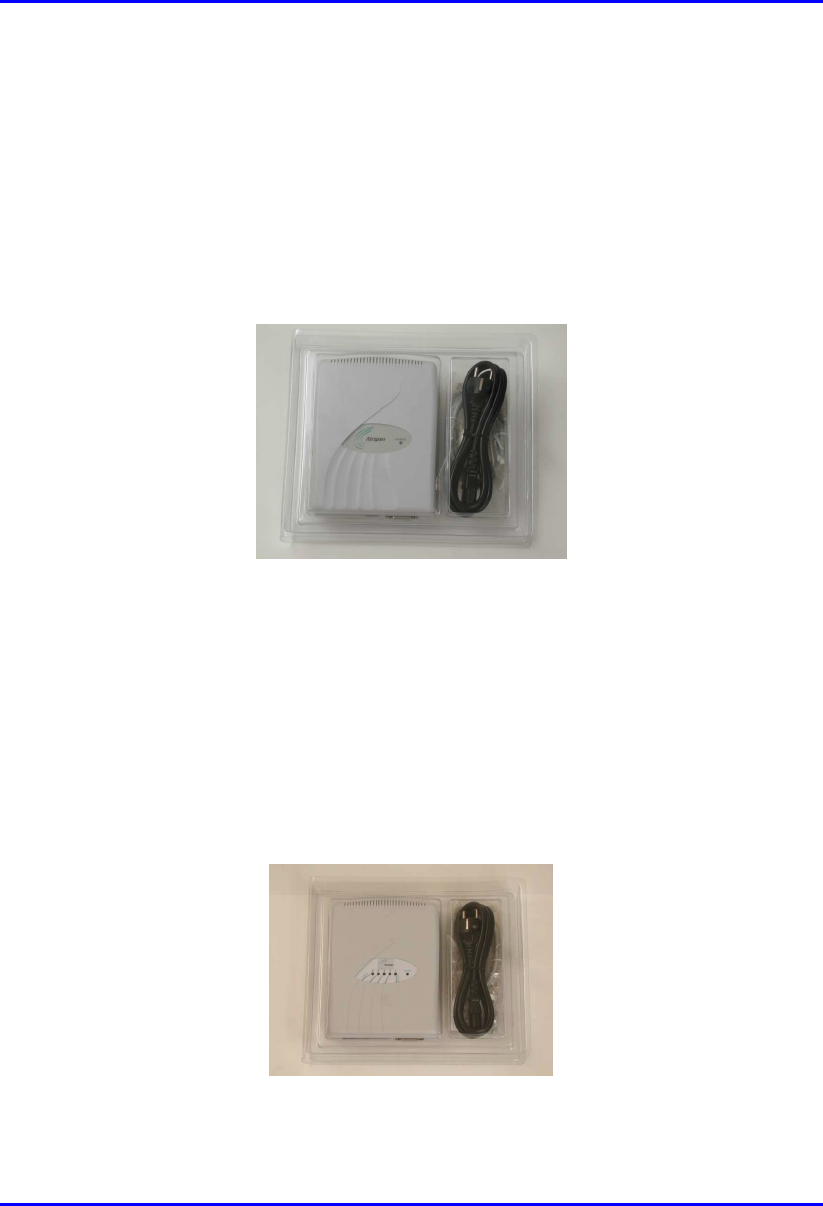
3.1.2.3.1. SDA-1
The SDA-1 provides one 10Base-T connection to a host PC or network. The SDA-1
includes the following parts:
! SDA-1 chassis
! Power cable
Figure 3-5: SDA-1 kit
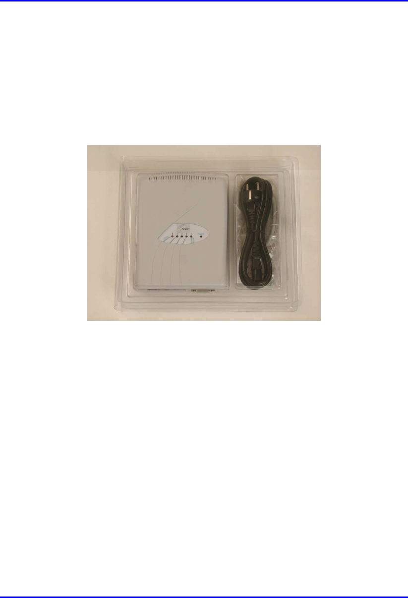
3.1.2.3.2. SDA-4H
The SDA-4H includes four interfaces: three for PC connection; one for daisy-
chaining to another hub or a LAN switch. The SDA-4H includes the following parts:
! SDA-4H chassis
! Power cable
Figure 3-6: SDA-4H kit
Part List and Required Tools Hardware Installation Gקגןו
3-8 Airspan Networks Ltd. 02030311-05
3.1.2.3.3. SDA-4S
The SDA-4S includes four 10/100Base-T interfaces for PC connection. The SDA-4S
kit includes the following parts:
! SDA-4S chassis
! Power cable
Figure 3-7: SDA-4S kit
Hardware Installation Gקגןו Part List and Required Tools
02030311-05 Airspan Networks Ltd. 3-9
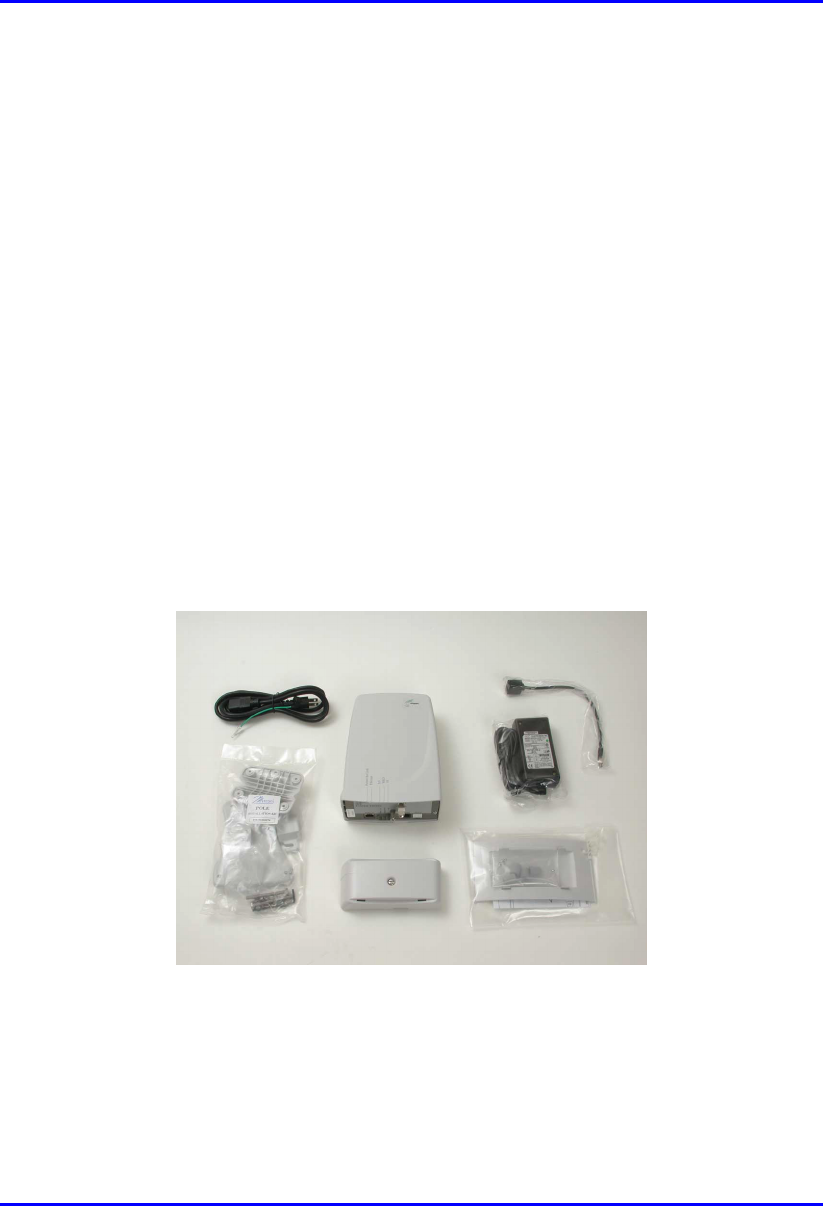
3.1.2.4. IDR kit
The IDR unit is an optional customer premises equioment that replaces the SPR and
SDA. The IDR combines the SPR and SDA in one unit.
The IDR is available in two models: IDR with external antenna; IDR with internal
antenna. These two IDR models have the same parts, except that the IDR with
external antenna model has a connector for attaching a third-party antenna.
The IDR unit includes the following parts:
! Chassis
! Power cable
! Power supply unit
! Ethernet cable
! Mounting stand
Figure 3-8: IDR kit

Part List and Required Tools Hardware Installation Gקגןו
3-10 Airspan Networks Ltd. 02030311-05
3.2. Required Tools
The following tools are required for installing the WipLL system:
! Pin crimper tool for CAT-5e cables for 15-Pin D-type and N-type connectors,
and for GPS connectros
! Cable stripping tool
! Philips screw driver
! Flat-blade screwdriver
! Adjustable wrench
! ESD-prevention wrist strap
! Torque wrench for N-type connectors
! IDR unit:
! Flat blade screwdriver
! Pozidriv screwdriver
! 3 mm A/F Allen key
! 10 mm A/F open ended spanner

Part I
Part IPart I
Part I
Installing WipLL
Installing WipLL Installing WipLL
Installing WipLL
Base Station Equipment
Base Station EquipmentBase Station Equipment
Base Station Equipment
Part I describes the procedures for installing the WipLL base station equipment, and
includes the following chapters:
! Chapter 4, “Installing the BSR”
! Chapter 5, “Installing the BSDU”
! Chapter 6, “Installing the GPS”
! Chapter 7, “Installing the BSPS”
This page is intentionally left balnk.

02030311-05 Airspan Networks Ltd. 4-1
Installing the BSR
Installing the BSRInstalling the BSR
Installing the BSR
This chapter describes the installation of the WipLL Base Station Radio (BSR),
which is installed at the base station.
This chapter includes the following sections:
! Overview
! Physical Dimensions and Basic Design
! Cable Installation Guidelines
! Connecting BSR for Serial Configuration
! Connecting BSR to the Backhaul Network
! Through the SDA
! Through the BSDU
! Conecting a Third-Party External Antenna (Optional)
! Connecting BSR to Power
! Mounting the BSR
! Minimum Distance Between BSRs
! Wall Mounting
! Pole Mounting
4

Installing the BSR Hardware Installation Guide
4-2 Airspan Networks Ltd. 02030311-05
4.1. Overview
The BSR is the center of the WipLL system. The BSR provides last-mile wireless
connectivity by connecting the provider’s backhaul network to the subscriber’s
wireless unit (Subscriber Premises Radio [SPR]). In addition, the BSR is responsible
for synchronizing the WipLL network (i.e., synchronizing SPRs/IDRs).
For base stations consisting of a single BSR, the BSR is typically powered and
connected to the provider’s backhaul network by the WipLL Subscriber Data
Adapter (SDA). For base stations consisting of multiple BSRs, the BSRs are
powered and connected to the provider’s backhaul by the WipLL Base Station
Distribution Unit (BSDU).
The BSR is available in three models:
! BSR with a built-in antenna
! BSR with an N-type port for connection to an optional third-party external
antenna
! BSR with an two N-type ports for connection to two optional third-party external
antennas for dual antenna diversity
Hardware Installation Guide Installing the BSR
02030311-05 Airspan Networks Ltd. 4-3
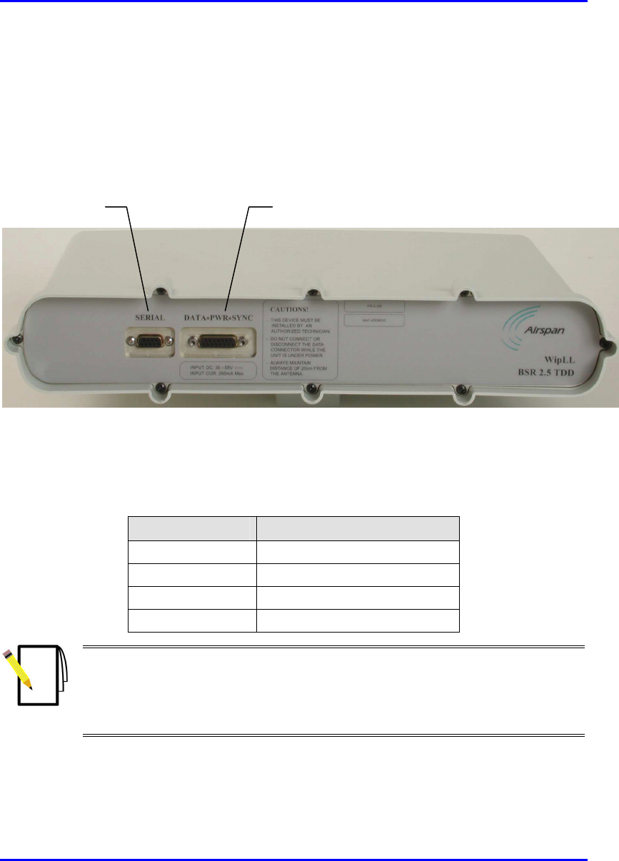
4.2. Physical Dimensions and Basic Design
The BSR is encased in a chassis providing access to the BSR’s communication port
on the front panel (see Figure 4-1). The BSR’s bottom panel provides holes for
mounting the BSR to, for example, a pole or wall (see Figure 4-11).
Figure 4-1: BSR front panel (internal antenna model)
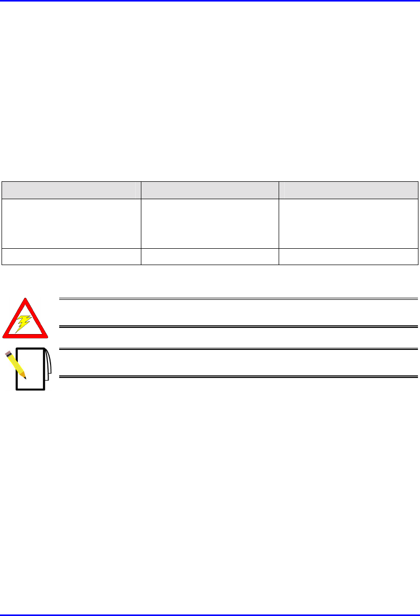
The BSR’s physical dimensions are described in Table 4-1
Table 4-1: BSR Physical Dimensions
Parameter Value
Height 400 mm (15.74 inches)
Width 317 mm (12.48 inches)
Depth 65.5 mm (2.58 inches)
Weight 4.7 kg
Notes:
1) The BSR’s physical dimensions exclude the mounting kit.
2) A BSR model with an N-type receptacle for attaching a third-party external
antenna is also available (see Section 4.6, “Conecting a Third-Party External
Antenna (Optional)”.
Serial port Data, power, and synchronization port
Installing the BSR Hardware Installation Guide
4-4 Airspan Networks Ltd. 02030311-05
4.3. Cable Installation Guidelines
This section defines the procedures to be adhered to when installing data cables at
the base station.
Warning: Pre-terminated cables should be fitted with protective poly bags
during cable installation processes.
Metal cable trays shall be earthed to a central earth point within the customers’
equipment room.
Note: A minimum separation of 200 mm should exist between power and data
cables.
The following points are to be considered:
! When installing network cables, ensure they are not damaged by friction or sharp
edges. Spacing of installation personnel at regular distances during any cable
drawing-in process will avoid contact with potential hazards.
! Data cables providing connection to the customers network shall be run in
suitable conduits. Cable conduits should be secured to the wall in accordance
with manufacturers instructions.
! Cables should be carefully fed through conduits and not pulled by means of any
attached connector.
! Sufficient space should be provided in cable ducts, trunking or trays (where
possible) to allow for future cabling growth.
! External data cables are to be protected in protective conduit, which is to be
secured to the building structure in accordance with manufacturers
recommendations. Trunking must not be located as to provide a trip hazard at the
base station premises (e.g. roof walkways)
! BSR cables are to be dressed tidily to the mounting pole or bracket using
strategically placed cable ties.
Hardware Installation Guide Installing the BSR
02030311-05 Airspan Networks Ltd. 4-5
! Observe recommended minimum bend radii when installing copper cables.
Wherever a cable changes direction, ensure that it does so in a smooth curve
with a radius of at least 50 mm to prevent damage.
! A maintenance loop is to be left in the cable just before the cable reaches the
BSR or GPS to prevent strain on the connector.
! Data cables entering holes drilled in walls are to be dressed to provide a loop that
will prevent water ingress into the building along the cable.
! Silicone sealant should be used to plug any holes on both internal and external
wall surfaces once cables are in place.
! All data cables should be labeled with both the source and destination at each
end.
Note: The maximum cable length between the BSR and terminating equipment
is 100 meters.
Installing the BSR Hardware Installation Guide
4-6 Airspan Networks Ltd. 02030311-05
4.4. Connecting BSR for Serial Configuration
The BSR provides a serial port for RS-232 serial interface to a PC. This serial
communication connection allows you to perform BSR initial configuration.
Notes:
1) For serial configuration, the BSR must remain connected to the BSDU/SDA
(i.e., the BSR’s 15-pin D-type port remains connected to the BSDU’s/SDA’s 15-
pin D-type port).
2) For a detailed explanation on performing BSR initial configuration using
WipLL’s management applications, refer to WipConfig User’s Guide and
WipConfig PDA User’s Guide.
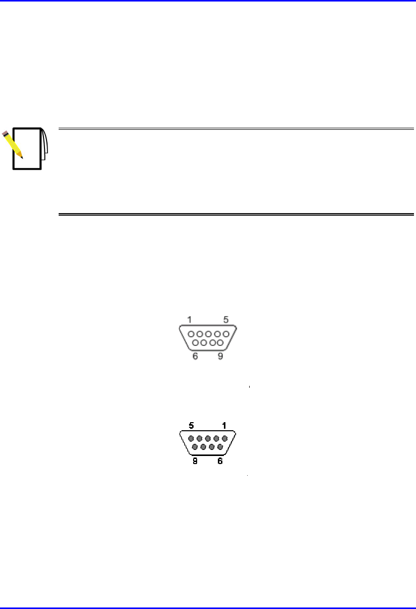
The BSR-to-PC management station serial cable connections include the following
! Cable: Crossover serial cable
! Connectors:
! BSR: 9-pin D-type male
Figure 4-2: 9-pin D-type male connector
! PC: 9-pin D-type female (RS-232)
Figure 4-3: 9-pin D-type female connector
Hardware Installation Guide Installing the BSR
02030311-05 Airspan Networks Ltd. 4-7
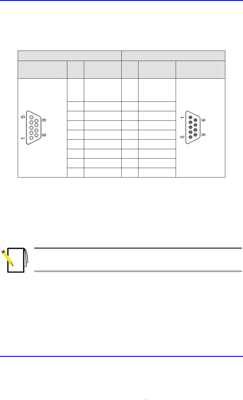
! Connector pinouts:
Table 4-2: BSR-to-PC serial connector pinouts
BSR PC
9-pin D-type
male
Pin Function Pin Function 9-pin D-type
female
1 Not
connected
(NC)
1 NC
2 RS232 Rx 3 Tx
3 RS232 Tx 2 Rx
4 NC 6 NC
5 GND 5 GND
6 NC 4 NC
7 NC 8 NC
8 NC 7 NC
9 NC 9 NC
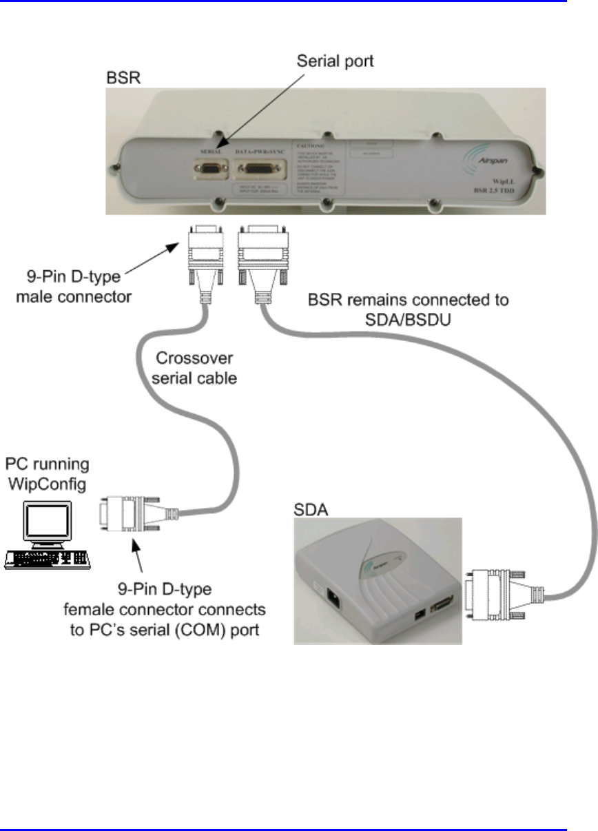
To connect the BSR to the PC and SDA/BSDU for serial configuration:
1. Connect the serial cable’s 9-pin D-type male connector to the BSR’s 9-pin D-
type port labeled SERIAL, as displayed in Figure 4-4.
2. Connect the serial cable’s 9-pin D-type female connector to the PC’s serial port,
as displayed in Figure 4-4.
Note: Ensure that the BSR remains connected to the BSDU/SDA (i.e., the
BSR’s 15-pin D-type port remains connected to the BSDU’s/SDA’s 15-pin D-
type port).
Installing the BSR Hardware Installation Guide
4-8 Airspan Networks Ltd. 02030311-05
Figure 4-4: BSR-to-PC serial connection

Hardware Installation Guide Installing the BSR
02030311-05 Airspan Networks Ltd. 4-9
4.5. Connecting BSR to the Backhaul Network
The BSR connection to the provider’s backhaul network depends on the base
station’s configuration:
! Base station consisting of a single BSR: connection to the backhaul is through
the SDA
! Base station consisting of multiple BSRs: connection to the backhaul is
through the BSDU.
4.5.1. Through the SDA
For a base station consisting of a single BSR, the BSR’s power supply and
connectivity to the backhaul network is provided by the SDA. The SDA is typically
installed at the subscriber’s premises, but in such a scenario, the SDA can also be
used at the base station. For a detailed description of the SDA, see Chapter 9,
“Installing the SDA”.
The BSR-to-SDA cable connection configurations are as follows:
! Connectors:
! BSR: 15-pin D-type male (only 8 pins are used)
! SDA: 15-pin D-type male (only 8 pins are used)
! Cable: straight-through CAT-5
Installing the BSR Hardware Installation Guide
4-10 Airspan Networks Ltd. 02030311-05
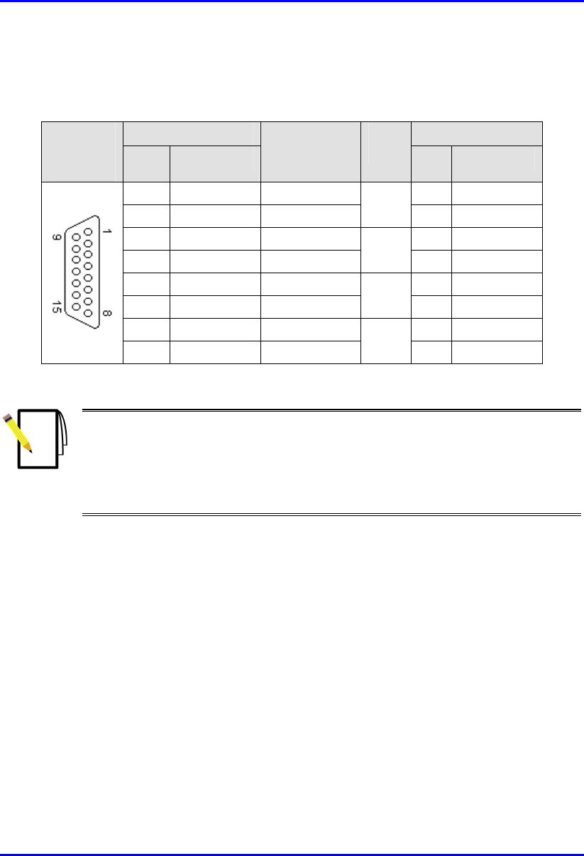
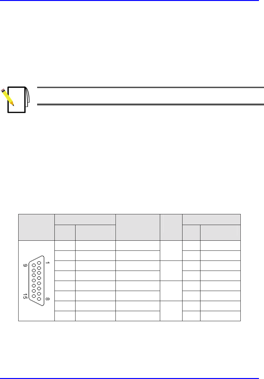
! Connector pinouts:
Table 4-3: BSR-to-SDA 15-pin D-type connector pinouts
BSR SDA 15-pin
D-type
male Pin Function
Wire color Wire
pair Pin Function
1 +48 VDC Blue / white 1 +48 VDC
2 -48 VDC Blue
1
2 -48 VDC
3 Tx+ Orange / white 3 Rx+
4 Tx- Orange
2
4 Rx-
5 Rx+ Green / white 5 Tx+
6 Rx- Green
3
6 Tx-
7 Sync.+ Brown / white 7 Sync.+
8 Sync.- Brown
4
8 Sync.-
Notes:
- Pins 9 through 15 of the 15-pin D-type connector are not used.
- The wire color-coding described in the table is WipLL's standard for wire
color-coding. However, if you implement your company's wire color-coding
scheme, ensure that the wires are paired and twisted according to the pin
functions listed in Table 4-3 (e.g., Rx+ with Rx-).
Hardware Installation Guide Installing the BSR
02030311-05 Airspan Networks Ltd. 4-11
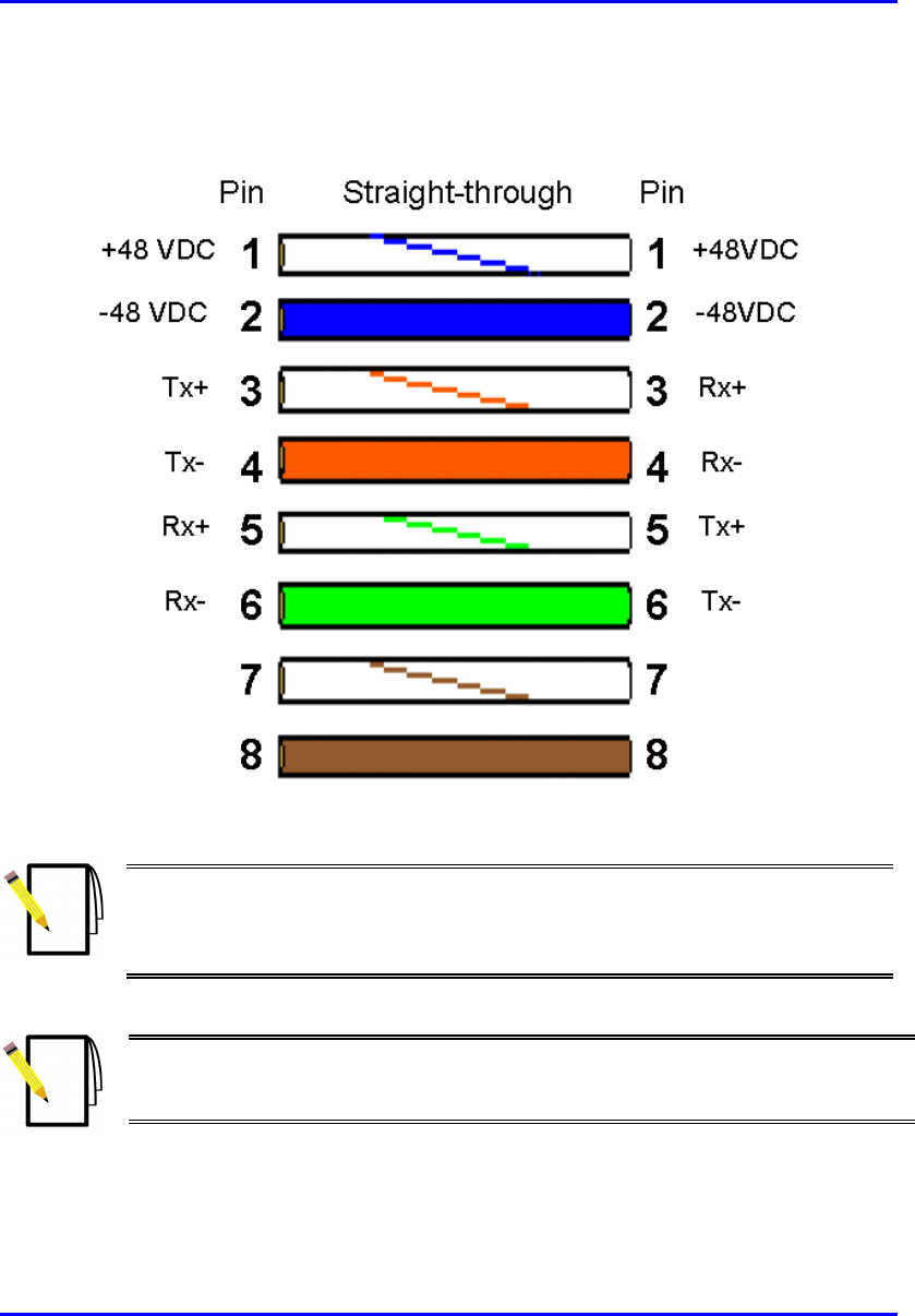
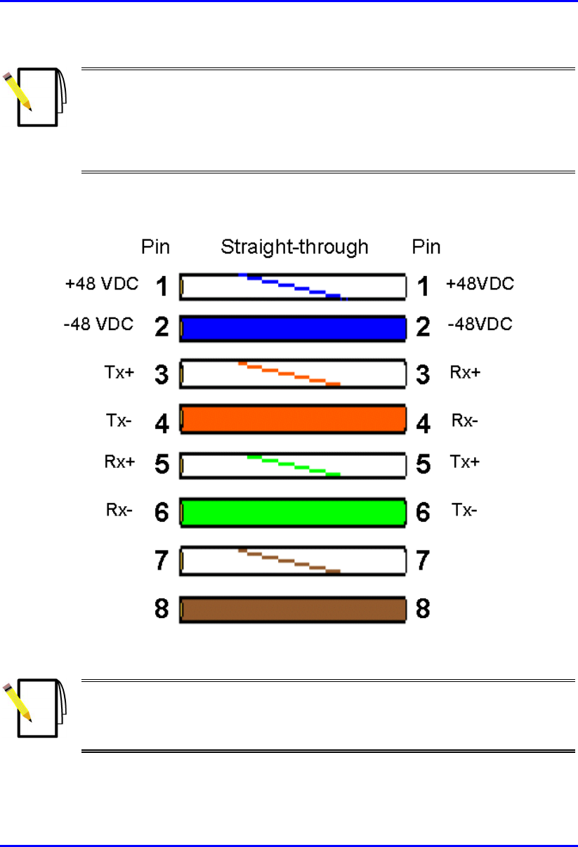
WipLL uses the following wire color-coding standards for CAT 5 cables with 15-pin
D-type to 15-pin D-type connectors on either ends (8 wires used):
Figure 4-5: WipLL wire color-coding for 15-pin D-type connectors
Note: The wires are twisted together in pairs, for example, blue/white with
blue, and orange/white with orange. This prevents electrical interference
between the transmitter pins. For example, pin 3 (Tx+; orange / white) is paired
and twisted with pin 4 (Tx-; orange).
Note: Airspan supplies unterminated cables for 15-Pin D-type connectors. Refe
r
to the cable crimping procedures for 15-Pin D-type connectors detailed in
Appendix B, “Cable Crimping".
Installing the BSR Hardware Installation Guide
4-12 Airspan Networks Ltd. 02030311-05
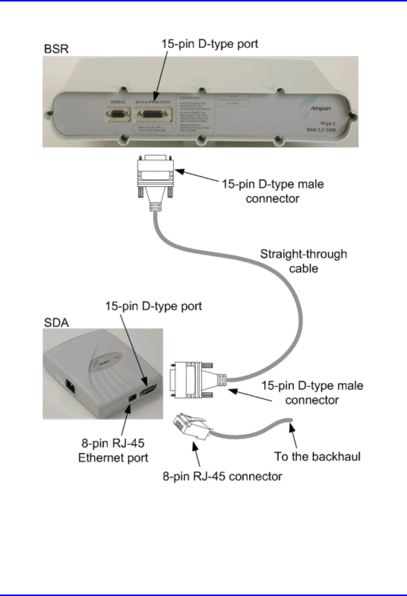
To connect the BSR to the backhaul through the SDA:
1. Attach the 15-pin D-type connector, at one end of the cable, to the BSR’s 15-pin
D-type port labeled DATA POWER SYNC, as displayed in Figure 4-6.
2. Attach the 15-pin D-type connector, at the other end of the cable, to the SDA’s
15-pin D-type port, as displayed in Figure 4-6.
3. Connect the SDA’s RJ-45 Ethernet port to the backhaul.
Note: For a detailed description of the SDA models, see Chapter 9, “Installing
the SDA”.
Hardware Installation Guide Installing the BSR
02030311-05 Airspan Networks Ltd. 4-13
Figure 4-6: Connecting BSR to the backhaul through the SDA
Installing the BSR Hardware Installation Guide
4-14 Airspan Networks Ltd. 02030311-05
4.5.2. Through the BSDU
For base stations consisting of multiple BSRs, the power supply and connectivity to
the backhaul network is provided by the BSDU. The BSR’s 15-pin D-type port is
connected to the BSDU’s rear panel 15-pin D-type port (labeled BSR #).
Note: For a detailed description of the BSDU, see Chapter 5, “Installing the
BSDU”.
The BSR-to-BSDU cable connection configurations is as follows:
! Connector:
! BSR: 15-pin D-type male (only 8 pins are used)
! BSDU: 15-pin D-type male (only 8 pins are used)
! Cable: straight-through 10Base-T Ethernet 4 Pair Cat 5 outdoor type – 24 AWG
! Connector pinouts:
Table 4-4: BSR-to-BSDU 15-pin D-type connector pinouts
BSR BSDU 15-pin
D-type
male Pin Function
Wire color Wire
pair Pin Function
1 +48 VDC Blue / white 1 +48 VDC
2 -48 VDC Blue
1
2 -48 VDC
3 Tx+ Orange / white 3 Rx+
4 Tx- Orange
2
4 Rx-
5 Rx+ Green / white 5 Tx+
6 Rx- Green
3
6 Tx-
7 Sync.+ Brown / white 7 Sync.+
8 Sync.- Brown
4
8 Sync.-
Hardware Installation Guide Installing the BSR
02030311-05 Airspan Networks Ltd. 4-15
Notes:
- Pins 9 through 15 of the 15-pin D-type connector are not used.
- The wire color-coding described in the table is WipLL's standard for wire
color-coding. However, if you implement your company's wire color-coding
scheme, ensure that the wires are paired and twisted according to the pin
functions listed in Table 4-3 (e.g., Rx+ with Rx-).
WipLL uses the following wire color-coding standards for CAT 5 cables with 15-pin
D-type to 15-pin D-type connectors on either ends (8 wires used):
Figure 4-7: WipLL wire color-coding for 15-pin D-type connectors
Note: The wires are twisted together in pairs, for example, blue/white with
blue, and orange/white with orange. This prevents electrical interference
between the transmitter pins. For example, pin 3 (Tx+; orange / white) is paired
and twisted with pin 4 (Tx-; orange).
Installing the BSR Hardware Installation Guide
4-16 Airspan Networks Ltd. 02030311-05
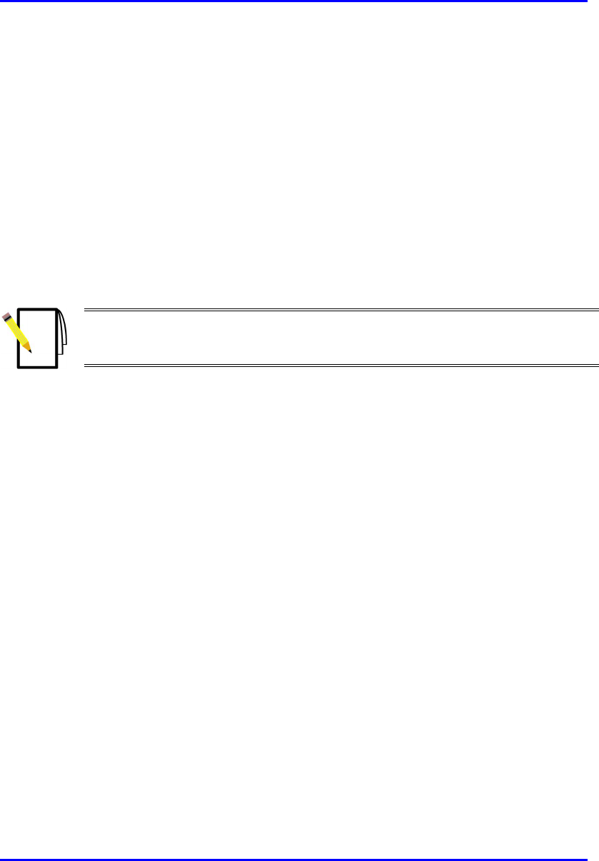
To connect the BSR to the backhaul through the BSDU:
1. Attach the 15-pin D-type connector, at one end of the cable, to the BSR’s 15-pin
D-type port labeled DATA POWER SYNC, as displayed in Figure 4-8.
2. Attach the 15-pin D-type connector, at the other end of the CAT-5 cable, to the
BSDU’s 15-pin D-type port labeled BSR, located at the rear of the BSDU, as
displayed in Figure 4-8.
3. Connect one of the BSDU’s 100Base-T ports, located at the front panel, to the
backhaul (see Chapter 5, “Installing the BSDU” for a detailed description of
connecting the BSDU to the backhaul).
Note: Airspan supplies unterminated cables for 15-Pin D-type connectors. Refe
r
to the cable crimping procedures for 15-Pin D-type connectors detailed in
Appendix B, “Cable Crimping".
Figure 4-8 displays the cable connections between the BSR and BSDU.
Hardware Installation Guide Installing the BSR
02030311-05 Airspan Networks Ltd. 4-17
Figure 4-8: BSR-to-BSDU cable connection
Installing the BSR Hardware Installation Guide
4-18 Airspan Networks Ltd. 02030311-05
4.6. Connecting a Third-Party External Antenna
(Optional)
The BSR model with an N-type connector can be connected to an external antenna.
The addition of an external antenna allows greater RF sector coverage than the
standard BSR Internal Antenna model (i.e., 60°). The BSR with an external antenna
is especially suited for base stations with one BSR, where sector coverage can be
increased to 360° by using an omni-antenna. The BSR model for the 900 MHz band
provides two N-type connectors for attaching two external antennas. This provides
dual antenna diversity.
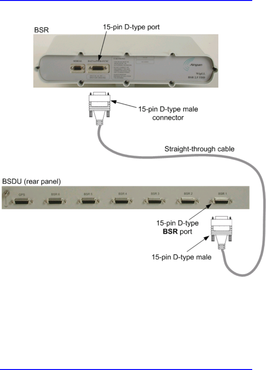
! Connector (third-party): N-type male (two N-type connectors for BSR model
for 900 MHz band. The N-type socket labelled Primary is used only if one
antenna is connected.)
Figure 4-9: Example of an N-type connector
! Cable (third-party): RF coaxial
Warnings:
1) Before connecting the external antenna, ensure that the BSR is NOT
connected to the power source.
2) Before powering on the BSR, ensure that some type of equiment such as
an antenna or an RF attenuator is connected to the N-type receptacle. This
eliminates the risk of burning the BSR device.
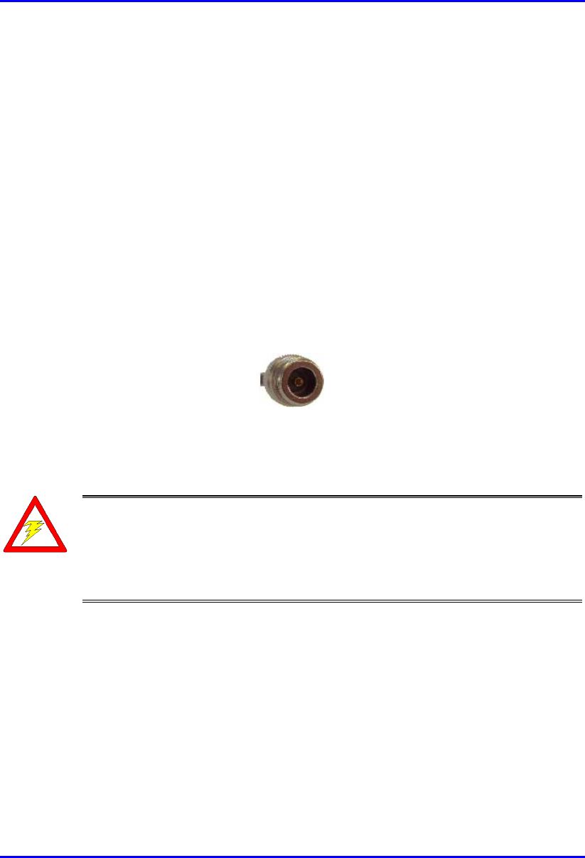
To connect the BSR to an external antenna:
! Attach the third-party N-type male connector to the N-type receptacle located on
the BSR’s front panel, as displayed in Figure 4-10.
Hardware Installation Guide Installing the BSR
02030311-05 Airspan Networks Ltd. 4-19
Notes:
1) For crimping cables for N-type connectors, see Appendix B, “Cable
Crimping”.
2) Ensure that the third-party antenna cable is of sufficient high quality to
reduce/eliminate loss when operating in the required frequency band.
Figure 4-10: Connecting BSR to N-type external antenna connector (third-party)
Warning: It is the responsibility of the person installing the WipLL system
to ensure that when using the outdoor antenna kits in the United States (o
r
where FCC rules apply), that only those antennas certified with the product are
used. The use of any antenna other than those certified with the product is
expressly forbidden in accordance with FCC rules CFR47 part 15.204. The
installer should configure the output power level of antennas according to
country regulations and per antenna type.
Installing the BSR Hardware Installation Guide
4-20 Airspan Networks Ltd. 02030311-05
4.7. Connecting BSR to Power
The BSR is powered by the SDA or BSDU (depending to which unit the BSR is
connected). The power is supplied through the BSR’s 15-pin D-type port, which is
connected to the SDA or BSDU.
The BSR’s power requirements are described in Table 4-5.
Table 4-5: BSR Power Requirements
Parameter Value Comment
Voltage:
• Minimum
• Maximum
48 VDC nominal
• 30 VDC
• 55 VDC
Voltage is received from the
BSDU or SDA
Maximum Amperes: 500 mA
Warning: If you are using an external antenna, ensure that you connect the
antenna before connecting the BSR to the power source.
Note: For details on connecting the SDA or BSDU to the mains power supply,
see Chapter 5, “Installing the BSDU” and Chapter 9, “Installing the SDA”.
Hardware Installation Guide Installing the BSR
02030311-05 Airspan Networks Ltd. 4-21
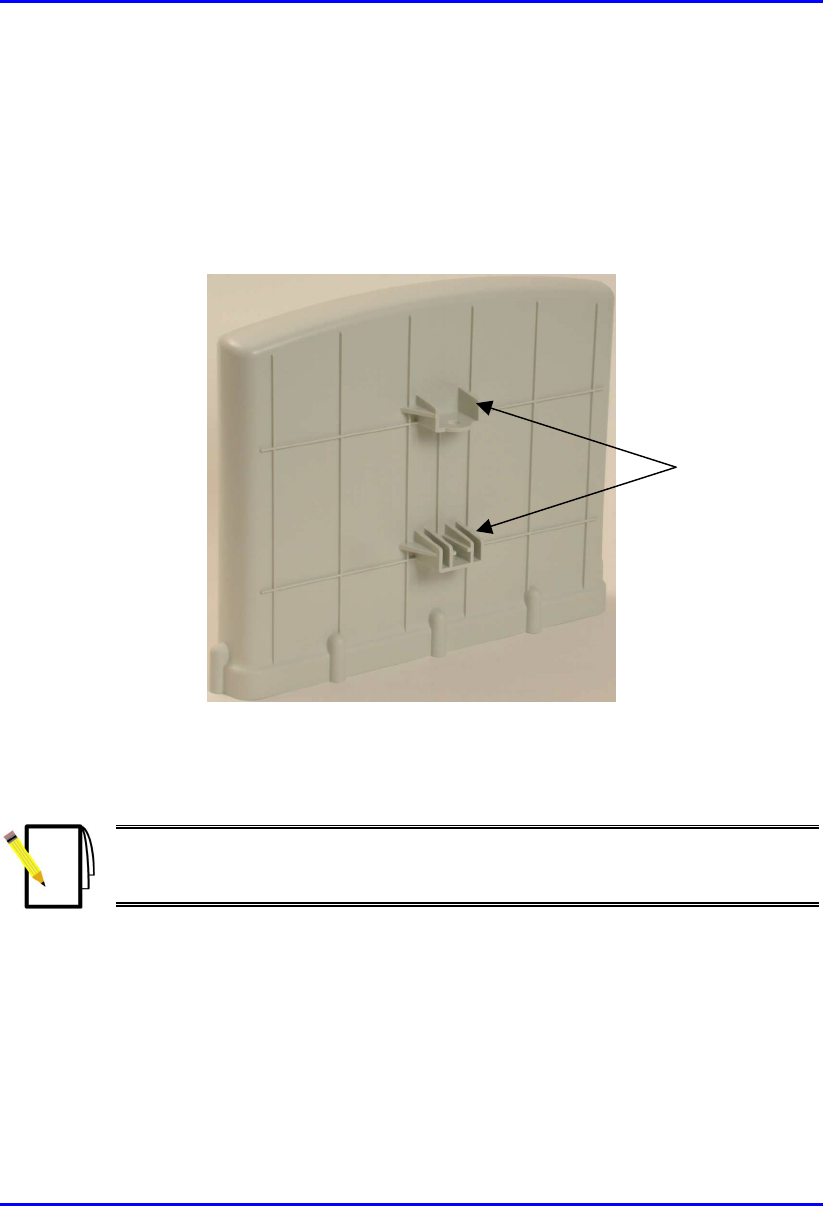
4.8. Mounting the BSR
The BSR can be mounted on a wall or pole. The BSR is mounted using the
mounting holes located on the BSR’s bottom panel (see Figure 4-11) and the
mounting bracket (provided by Airspan).
Figure 4-11: BSR bottom panel providing holes for mounting
The mounting brackets for BSR wall- and pole-mounting are different.
Note: The antenna used for this transmitter must be installed to provide
minimum separation distance of at least 20 cm from all persons and must not
be co-located or operated in conjunction with any other antenna or transmitter.
Mounting holes
Installing the BSR Hardware Installation Guide
4-22 Airspan Networks Ltd. 02030311-05
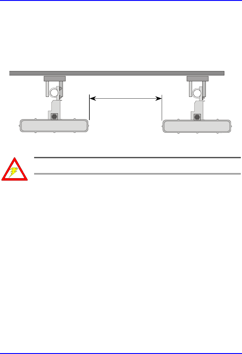
4.8.1. Minimum Distance Between BSRs
To prevent system interference, each BSR requires a minimum of 1-metre separation
between adjacent BSRs (see Figure 4-12).
1 Metre min.
Figure 4-12: Minimum distance between mounted BSRs
Warning: The BSR emits microwave radiation; a minimum distance o
f
200 mm must be maintained from the front of the BSR.
Hardware Installation Guide Installing the BSR
02030311-05 Airspan Networks Ltd. 4-23
4.8.2. Wall Mounting
BSR wall mounting is performed in two chronological stages:
! Attaching the mounting bracket to the BSR’s mounting holes
! Attaching the mounting bracket (attached to the BSR) to the wall
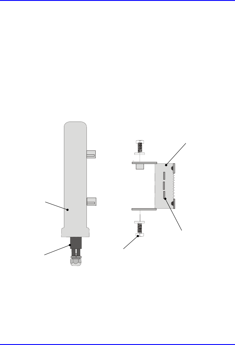
To mount the BSR on a wall:
1. Attach the mounting bracket to the BSR using two stainless steel bolts, as shown
in Figure 4-13.
Jubilee clip slots
BSR
BSR Fixing Bolts
BSR Mounting
Bracket
15-pin D-type
connector
Figure 4-13: Attaching the mounting bracket to the BSR
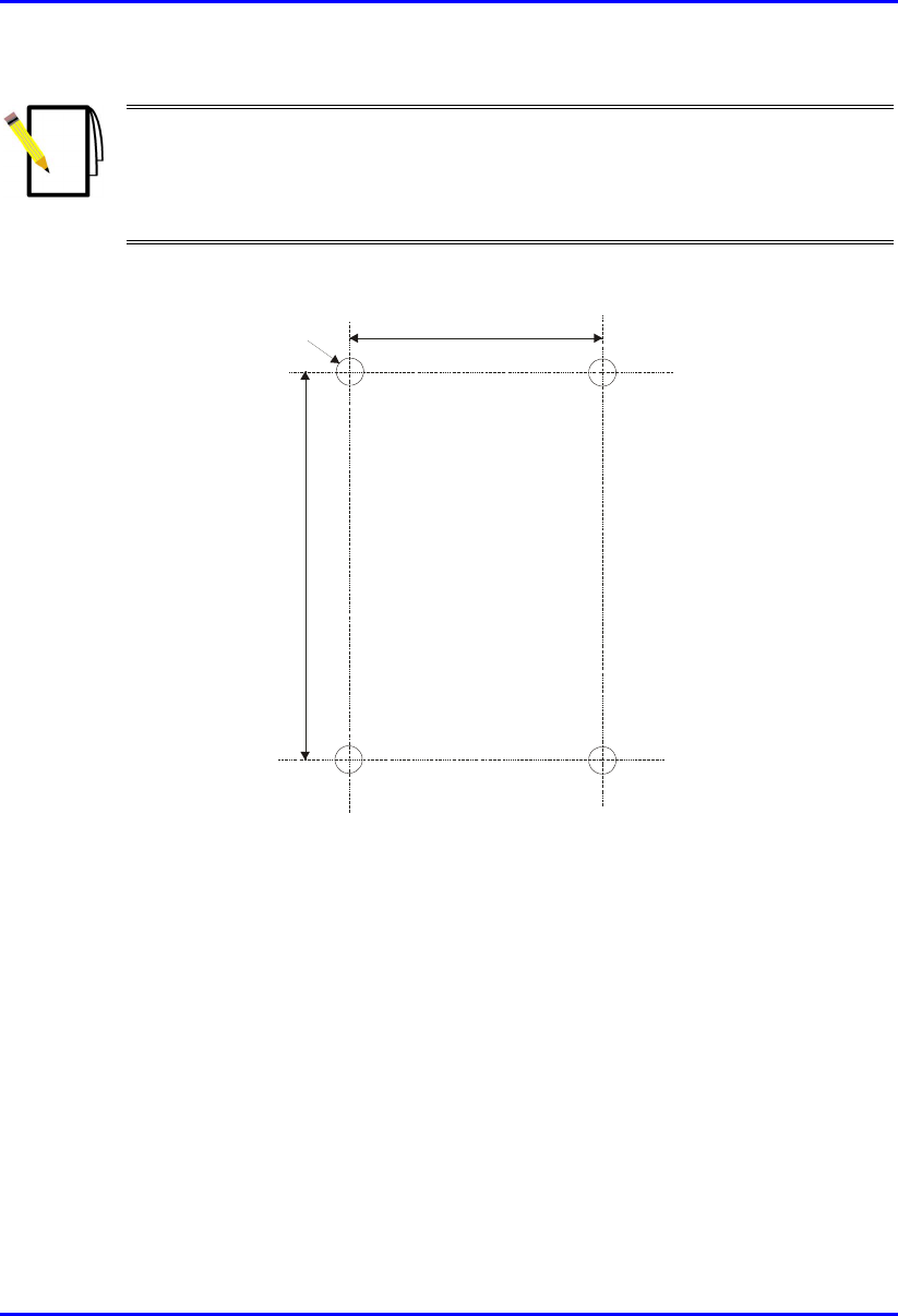
2. Attach the mounting bracket to the wall using four screws. The fixing
dimensions for the mounting bracket is illustrated in Figure 4-14
Installing the BSR Hardware Installation Guide
4-24 Airspan Networks Ltd. 02030311-05
Note: Airspan does not provide screws for attaching the mounting bracket to
the wall. The screw size depends on the structure of the building to which the
bracket is to be attached. When selecting screw sizes, consideration must be
given to the weight of the BSR and load that may be induced in windy
conditions.
.
58mm
8mm
99mm
Figure 4-14: BSR mounting bracket dimensions for the four fixing holes
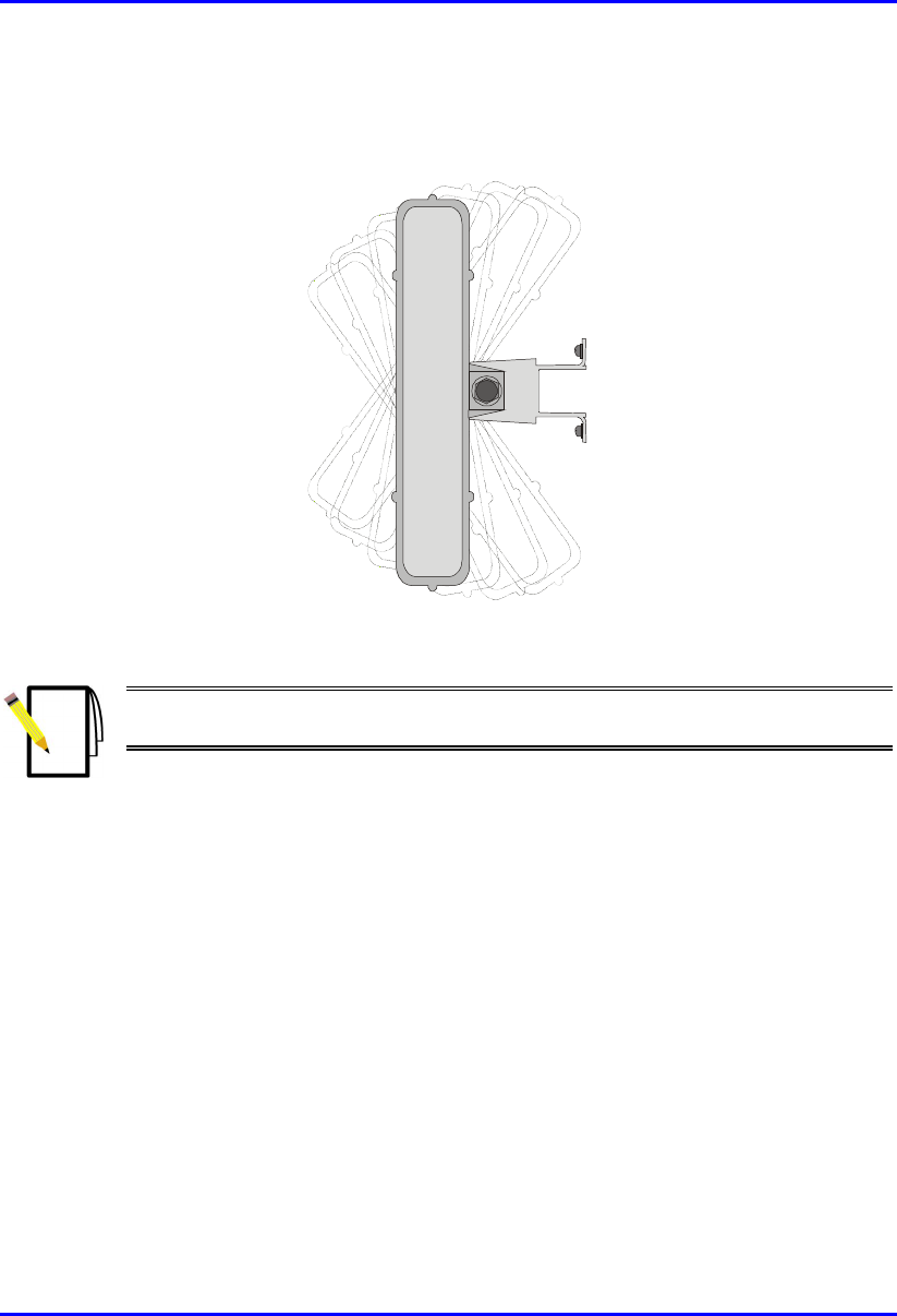
3. Adjust the horizontal positioning of the BSR, and then fasten tight the two
stainless-steel bolts.
Hardware Installation Guide Installing the BSR
02030311-05 Airspan Networks Ltd. 4-25
Rotation is restricted to the horizontal plane only. The permissible rotation is
shown in Figure 4-15.
Figure 4-15: Horizontal rotation of the BSR
Note: A thread-locking compound is to be used to prevent the bolts working
loose.
Installing the BSR Hardware Installation Guide
4-26 Airspan Networks Ltd. 02030311-05
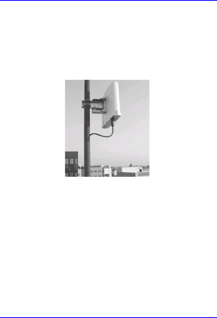
4.8.3. Pole Mounting
The BSR can be mounted on a pole (see Figure 4-16). Pole mounting allows the
BSR to be adjusted in the horizontal as well as the vertical plane. The pole-mounting
bracket assembly is designed to support the BSR on a round pole of 45 mm in
diameter.
Figure 4-16: Mounted BSR
Hardware Installation Guide Installing the BSR
02030311-05 Airspan Networks Ltd. 4-27
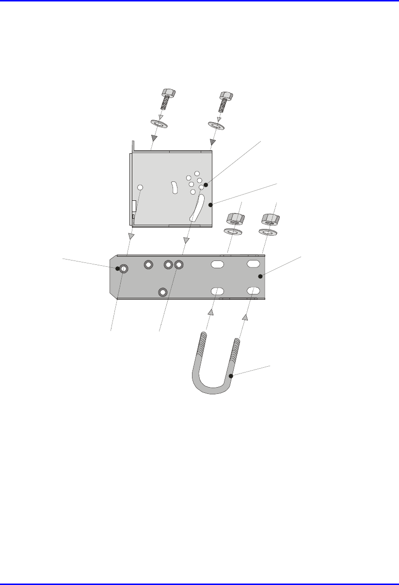
To mount the BSR on a pole:
1. Attach the mounting bracket to the BSR using two stainless steel bolts.
Pivot Hole
‘U’ Bolt
Locking Holes
BSR mounting
Bracket
Clamping Bracket
Figure 4-17: BSR mounting bracket assembly
2. Attach the clamping bracket to the mounting bracket using two M8 stainless
bolts.
3. Attach the Clamping bracket to the pole by placing the U-bolt around the pole,
and then inserting the U-bolt through the Clamping bracket and securing it by
screwing the two bolts on the U-bolt.
Installing the BSR Hardware Installation Guide
4-28 Airspan Networks Ltd. 02030311-05
4. Adjust the vertical position of the BSR. Lock the BSR at the desired position by
inserting the locking bolt in the desired position. Once the correct angle has been
set both bolts must be tightened to lock the BSR bracket in place.
5. Adjust the horizontal position of the BSR by rotating the BSR about the pole,
and then tighten the U-bolt.
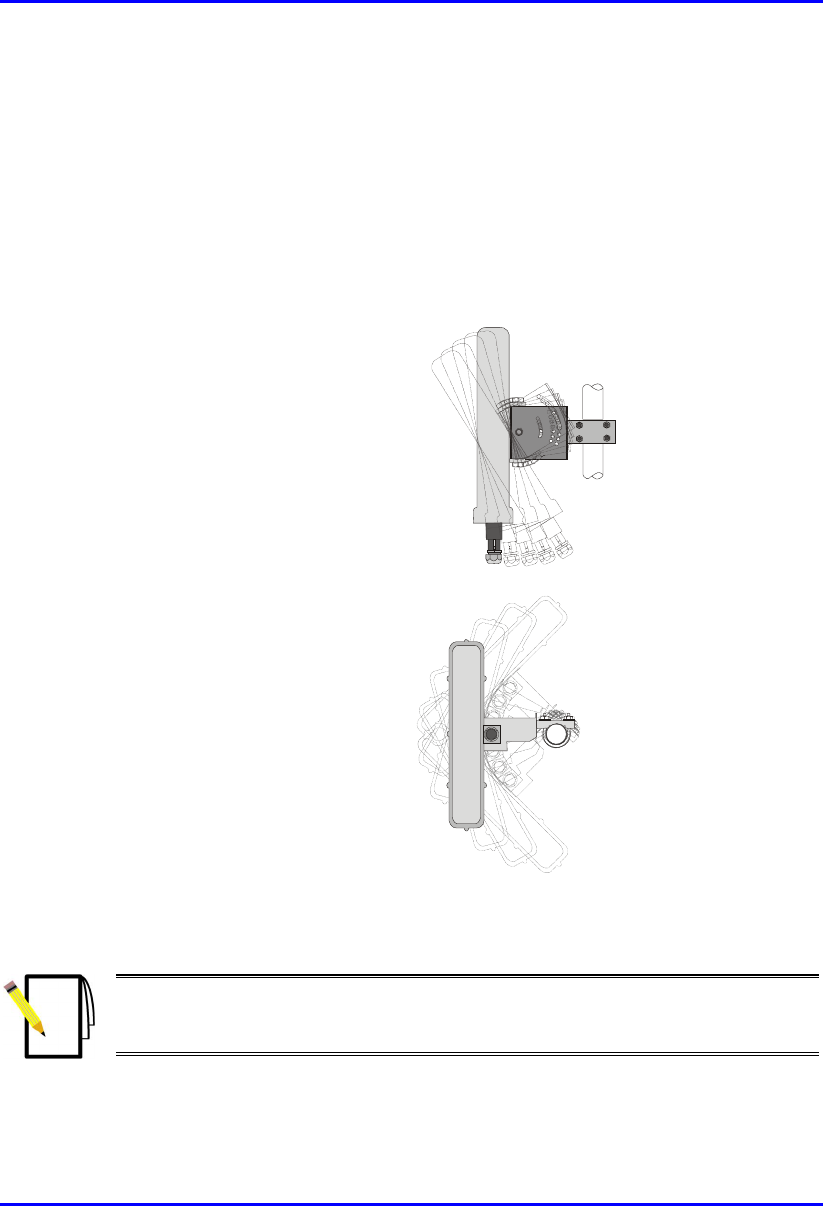
BSR positioning is obtained in two planes by adjustment of the mounting
bracket assembly a shown in Figure 4-18.
Rotation about the
mounting pole
Rotation about the
mounting bracket
Figure 4-18: BSR GPS orientation in vertical (top figure) and horizontal plane (lower
figure)
Note: A thread-locking compound is to be used to prevent the bolts working
loose. A loop should be left in the cable for maintenance purposes and to
prevent the cable weight being taken directly on the connector.

02030311-05 Airspan Networks Ltd. 5-1
Installing the BSDU
Installing the BSDUInstalling the BSDU
Installing the BSDU
This chapter describes the installation of the WipLL Base Station Distribution
Unit (BSDU), which is installed at the base station.
This chapter includes the following sections:
! Overview
! Physical Dimensions and Basic Design
! Rack-Mounting
! Connecting to BSRs
! Connecting to GPS Antenna
! Connecting to 100Base-T Networks
! Daisy-Chaining BSDUs
! Connecting Sync IN/OUT ports
! Connecting to BSPS for Power Management
! Connecting to PC for Serial Management
! Connecting to PC for Network IP Management
! Connecting to Power
! LED Indicators
5
Installing the BSDU Hardware Installation Guide
5-2 Airspan Networks Ltd. 02030311-05
Warning:
To avoid electrical shock and fire hazard ensure that all data and powe
r
connections are made prior to connecting the BSDU to the DC power supply.
When installing the BSDU, it is required that you wear the wrist strap for ESD
prevention.
Note: Airspan supplies unterminated cables for 15-Pin D-type and N-type
connectors. Refer to the cable crimping procedures for these connectors in
Appendix B, “Cable Crimping".
5.1. Overview
The WipLL BSDU is an optional WipLL device that connects multiple BSRs at a
base station. The BSDU is installed in a cabinet at the customer's base station.
The BSDU provides the following functionality:
! Serves up to six BSRs. Up to four BSDUs can be daisy-chained at a single base
station to support up to 24 BSRs.
! Power supply of –48 VDC to BSRs.
! Wide Area Network (WAN) interface to the provider’s backhaul network.
! Frequency-hop synchronization.
Hardware Installation Guide Installing the BSDU
02030311-05 Airspan Networks Ltd. 5-3
5.2. Physical Dimensions and Basic Design
The BSDU is encased in a chassis providing access to the BSDU's communication
ports on the front and rear panels. The BSDU can be mounted in a standard 19" rack
with 1-U vertical space requirement.
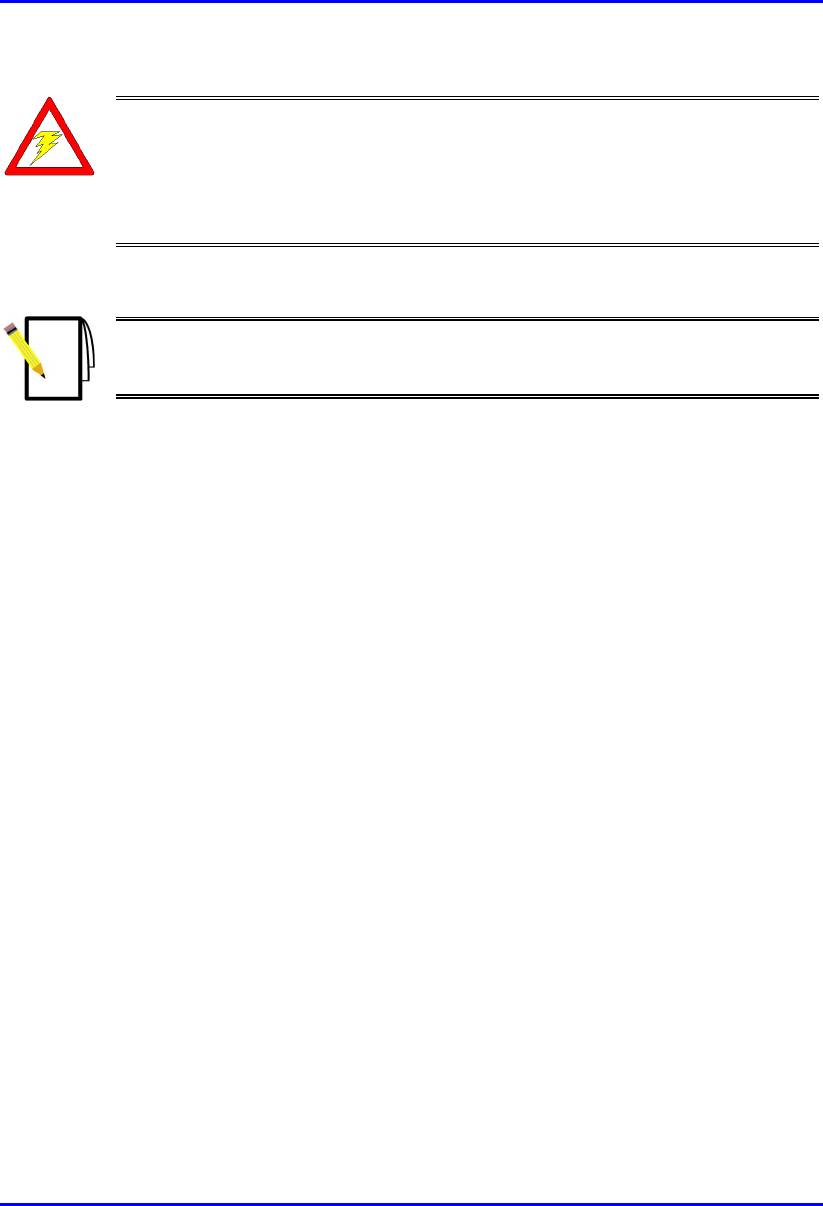
Figure 5-1 displays the BSDU's front panel.
Figure 5-1: BSDU front panel
The BSDU's front panel provides the following ports:
! Two RJ-45 100Base-T ports
! Two RJ-45 10Base-T ports
! One RJ-45 port (input) for synchronization with previous BSDU in ring
! One RJ-45 port (output) for synchronization with next BSDU in ring
! One 9-Pin D-type (female) monitor serial port for WipConfig interface
! One 9-Pin D-type (male) port for management interface with the Base Station
Power System (BSPS)
! DC power input connector –48 VDC
! Various LEDs
BSR’s LEDs
100Base-T LEDs Status LEDs Power receptacle
BSPS power
management port
10Base-T ports
Serial management port
Synchronization ports
100Base-T ports
Installing the BSDU Hardware Installation Guide
5-4 Airspan Networks Ltd. 02030311-05
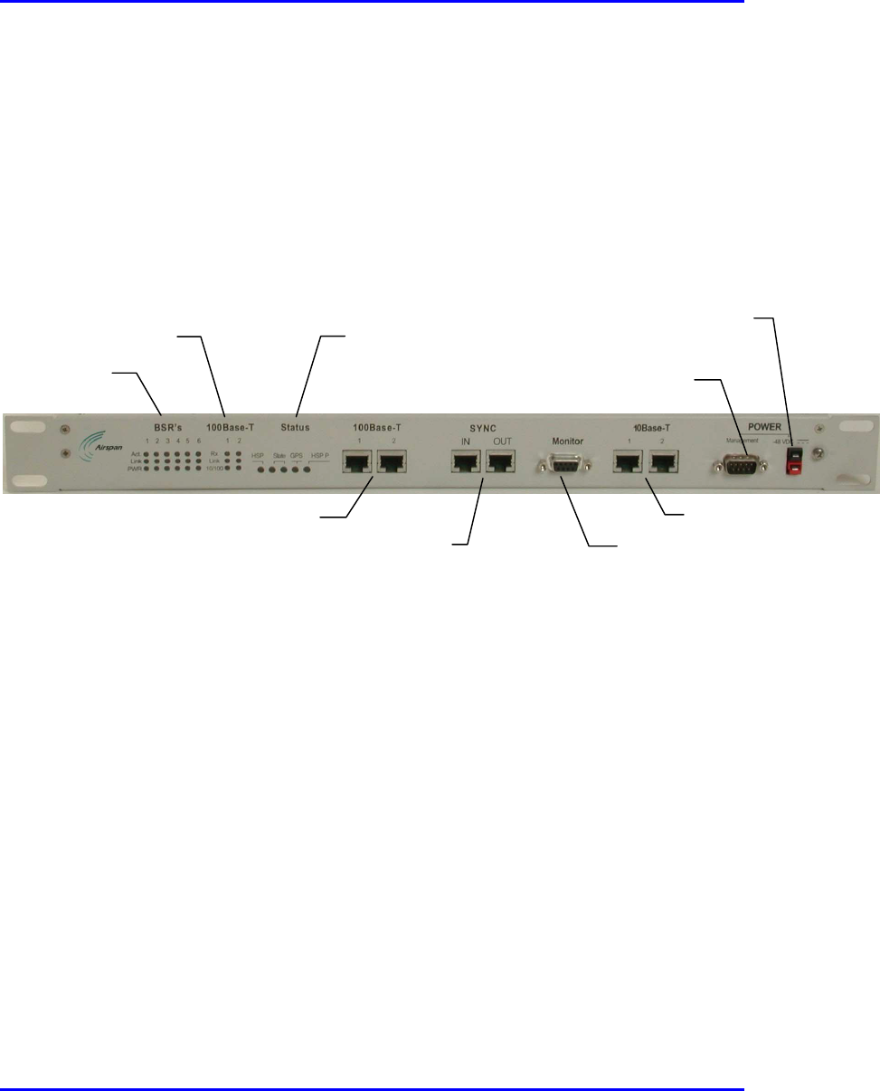
Figure 5-2 displays the BSDU's rear panel.
Earth Stud
GPS port
Six BSR ports
Figure 5-2: BSDU rear panel
The BSDU's rear panel provides the following ports:
! Six 15-Pin D-type connectors which provide DC power, Ethernet connection,
synchronization and serial interface to the BSR (up to six BSRs)
! One 15-Pin D-type connector for the Global Positioning System (GPS) antenna
! One 5-mm diameter grounding lug
The BSDU's physical dimensions are described in Table 5-1.
Table 5-1: BSDU physical dimensions
Parameter Value
Height 43.2 mm (1.7 inches)
Width 482.6 mm (19 inches)
Depth 228.6 mm (9 inches)
Weight 2.9 kg

Hardware Installation Guide Installing the BSDU
02030311-05 Airspan Networks Ltd. 5-5
5.3. Rack-Mounting
The BSDU is a 1U-chassis, which is installed in a standard 19" (inch) cabinet, and is
provided with front-rail mounting brackets. The mounting brackets are part of the
BSDU chassis. Therefore, all that is required for mounting the BSDU is to attach the
BSDU mounting brackets to the cabinet. The BSDU is secured to the cabinet’s
mounting rails using the supplied four M5 mounting screws and plastic cup washers.
To rack-mount the BSDU:
1. Determine which mounting rail holes of the cabinet—left and right side—will be
used for attaching the chassis.
2. Insert four nuts into the holes you specified in Step 1.These nuts are housed in
Tinnerman clips, which allow you to fasten them into the holes. To insert the
Tinnerman clips, hold the clips, squeeze them, and then insert them into the hole.
3. Carefully insert the BSDU into the cabinet, aligning the BSDU’s mounting
brackets with the holes.
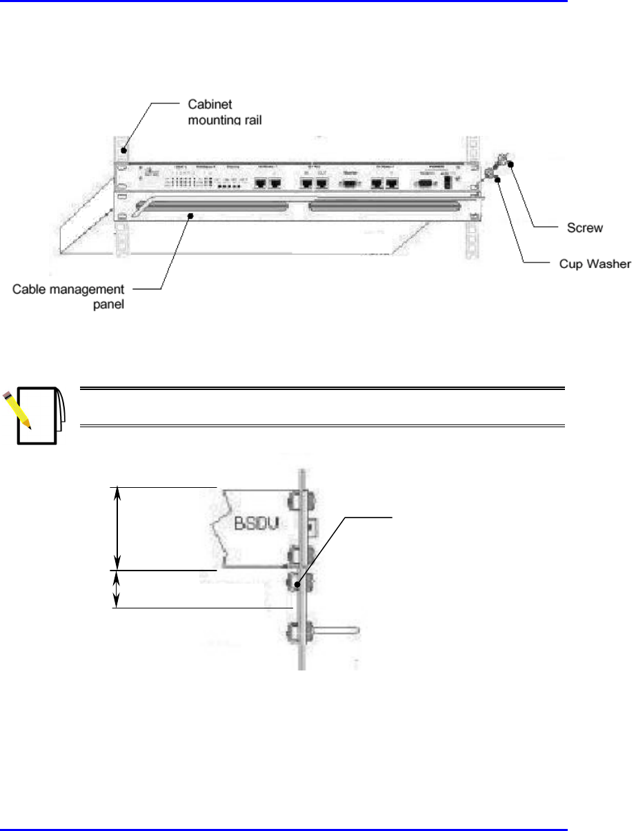
4. Insert the M5-mounting screws, with plastic washers, in the BSDU mounting
bracket screw holes, on each side, as shown Figure 5-3. In this way, the chassis
is supported until you tighten the chassis screws.
Installing the BSDU Hardware Installation Guide
5-6 Airspan Networks Ltd. 02030311-05
5. Tighten the M5 mounting screws to fasten the chassis to the cabinet.
Figure 5-3: BSDU rack mounting
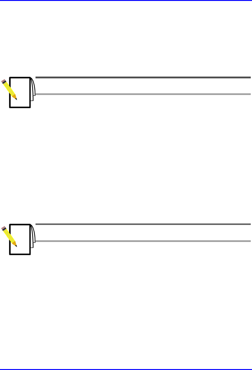
Note: When mounting multiple BSDUs in a cabinet, vertical space—above
and below—is required for threading cables to the rear.
Figure 5-4: BSDU and vertical space for cables
Space for cable
management
1U-chassis
Hardware Installation Guide Installing the BSDU
02030311-05 Airspan Networks Ltd. 5-7
5.4. Connecting to BSRs
The BSDU rear panel provides six 15-Pin D-type connectors for connecting a
maximum of six BSRs. For a detailed description of connecting BSRs to the BSDU,
see Chapter 4, “Installing the BSR”.
Note: A maximum of 4 BSDUs can be installed at a base station, allowing
maximum connection of up to 24 BSRs.
! Connector: 15-Pin D-type (male)
! Connector pinouts: see Chapter 4, “Installing the BSR”.
For a description of the BSDU’s BSR ports LED indicators, see Section 5.13.1,
“BSR’s LED”.
5.5. Connecting to the GPS Antenna
The rear panel of the BSDU provides a 15-Pin D-type connector port, labeled GPS
for connection to the GPS antenna for clock synchronization. The GPS allows
synchronization between base stations.
Note: For a detailed explanation on connecting the GPS to the BSDU port,
see Chapter 6, “Installing the GPS”.

Installing the BSDU Hardware Installation Guide
5-8 Airspan Networks Ltd. 02030311-05
5.6. Connecting to 100Base-T Networks
The BSDU’s front panel provides two RJ-45 ports for connection to 100Base-T
(labeled 100Base-T) ports. The 100Base-T ports are used for connection to the
WipLL management station and the service provider’s backbone (Ethernet).
! Connector: 8-Pin RJ-45 (male)
! Connector pinouts:
Pin Name Description
1 Tx+ Transmit Data+
2 Tx- Transmit Data-
3 Rx+ Receive Data+
4 NC Not connected
5 NC Not connected
6 Rx- Receive Data-
7 NC Not connected
8 NC Not connected

Hardware Installation Guide Installing the BSDU
02030311-05 Airspan Networks Ltd. 5-9
5.7. Daisy-Chaining BSDUs
You can daisy chain up to four BSDUs at each base station. When you daisy chain
BSDUs, you need to connect the 100Base-T ports between BSDUs using a
crossover cable.
! Connector: 8-pin RJ-45
! Cable: RJ-45-to-RJ-45 crossover
! Connector pinouts: The following table describes the pinouts of the RJ-45
connectors on opposite sides of the crossover cable:
RJ-45 (one end) RJ-45 (other end)
Pin Name
Description
Pin
1 Tx+ Transmit Data+ 3
2 Tx- Transmit Data- 6
3 Rx+ Receive Data+ 1
4 NC Not connected 4
5 NC Not connected 5
6 Rx- Receive Data- 2
7 NC Not connected 7
8 NC Not connected 8
To daisy-chain BSDUs:
1. On the first BSDU, connect the RJ-45 connector, on one end of the crossover
cable, to one of the two 100Base-T ports (labeled 100Base-T 1 or 100Base-T 2)
located on the BSDU’s front panel (see Figure 5-5).
2. On the second BSDU, connect the RJ-45 connector, at the other end of the
crossover cable, to one of the BSDU’s 100Base-T ports (labeled 100Base-T 1 or
100Base-T 2) located on the BSDU’s front panel (see Figure 5-5).
3. If there are additional BSDUs, simply continue connecting the BSDUs using the
100Base-T ports (see Figure 5-5).