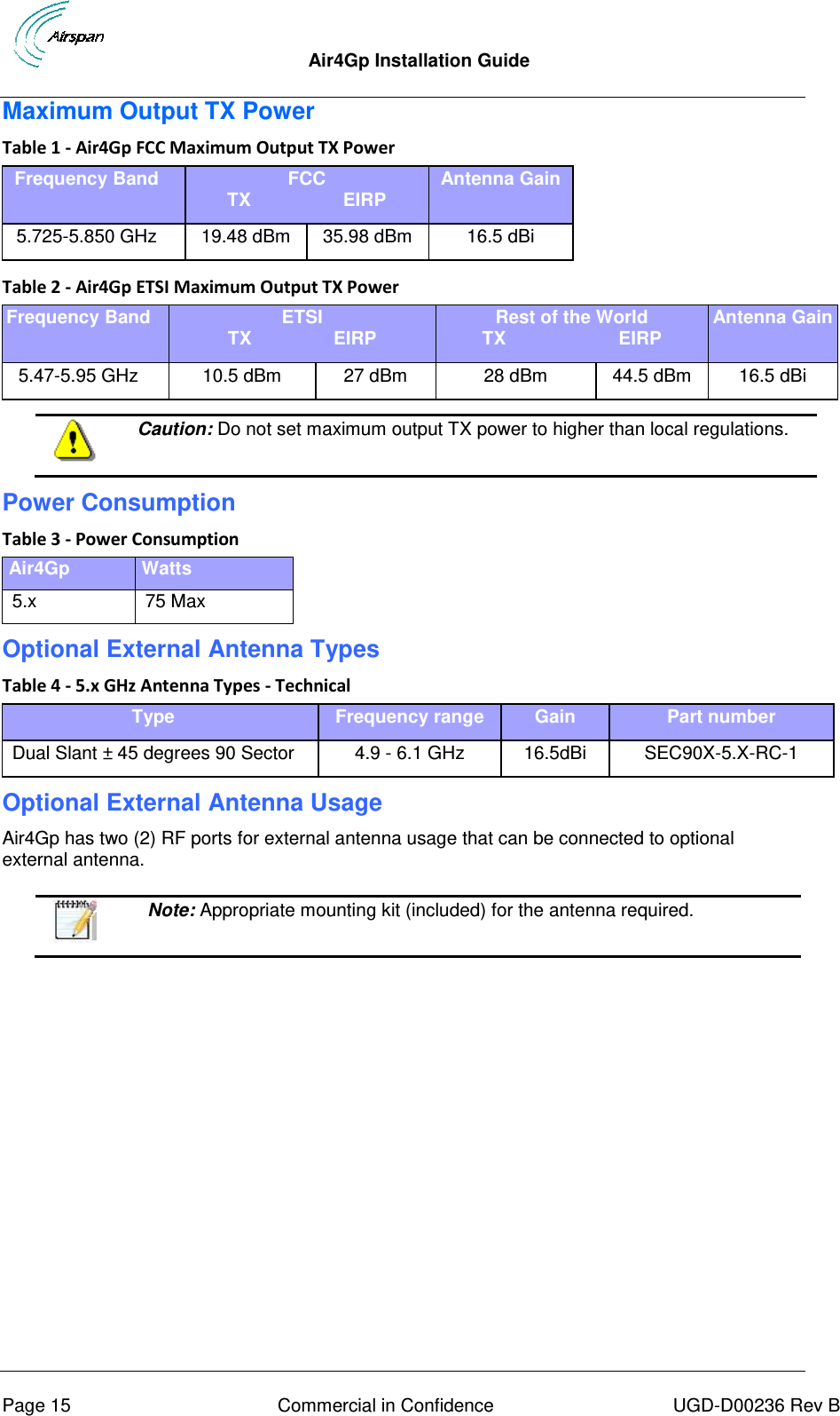
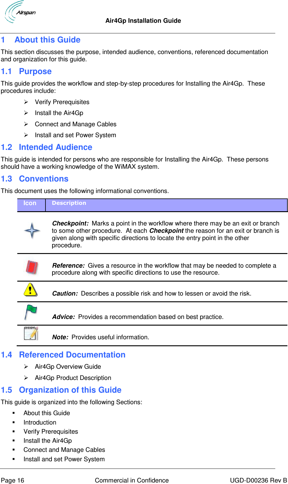
Airspan Networks MMAX5725 WiMAX base station User Manual Air4G Installation Guide
Airspan Networks Inc WiMAX base station Air4G Installation Guide
UserManual.wiki
>
Airspan Networks
>
MMAX5725 User Manual
user manual
Navigation menu
Upload a User Manual
Namespaces
Wiki Guide
HTML
PDF
Info
Views
User Manual
Discussion / Help
Navigation
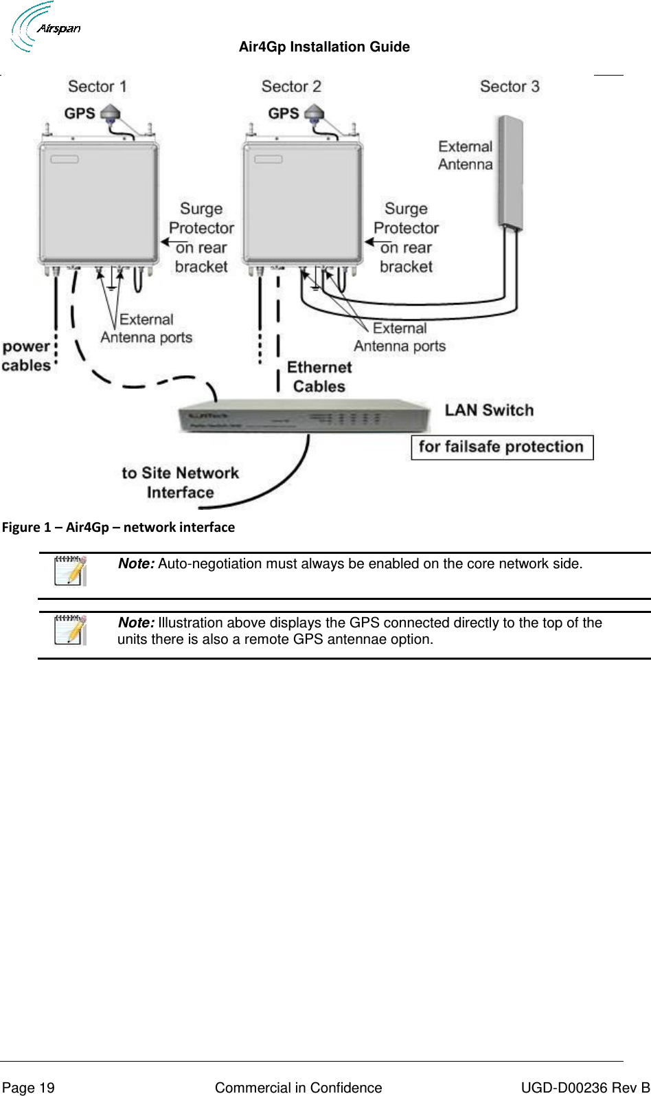
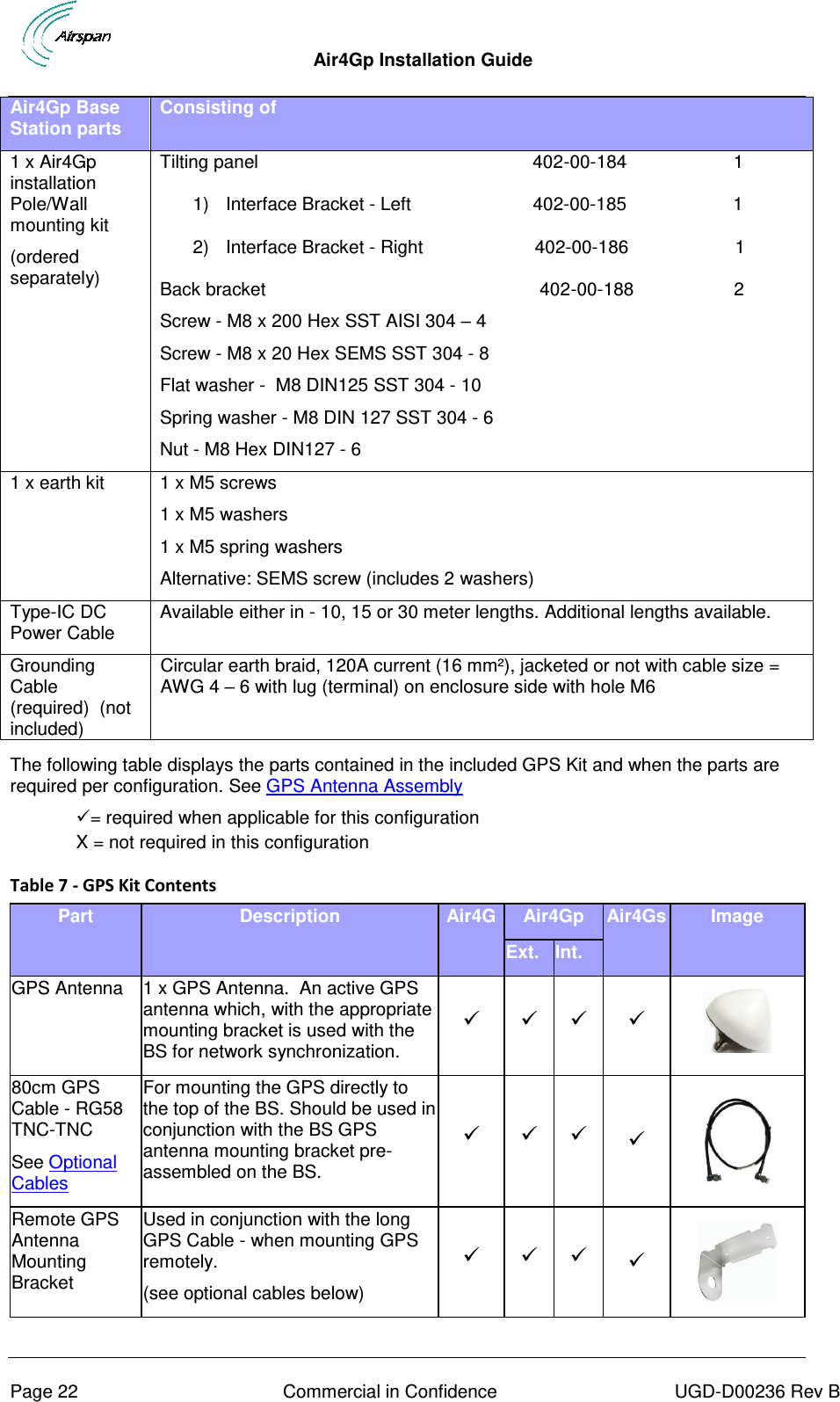
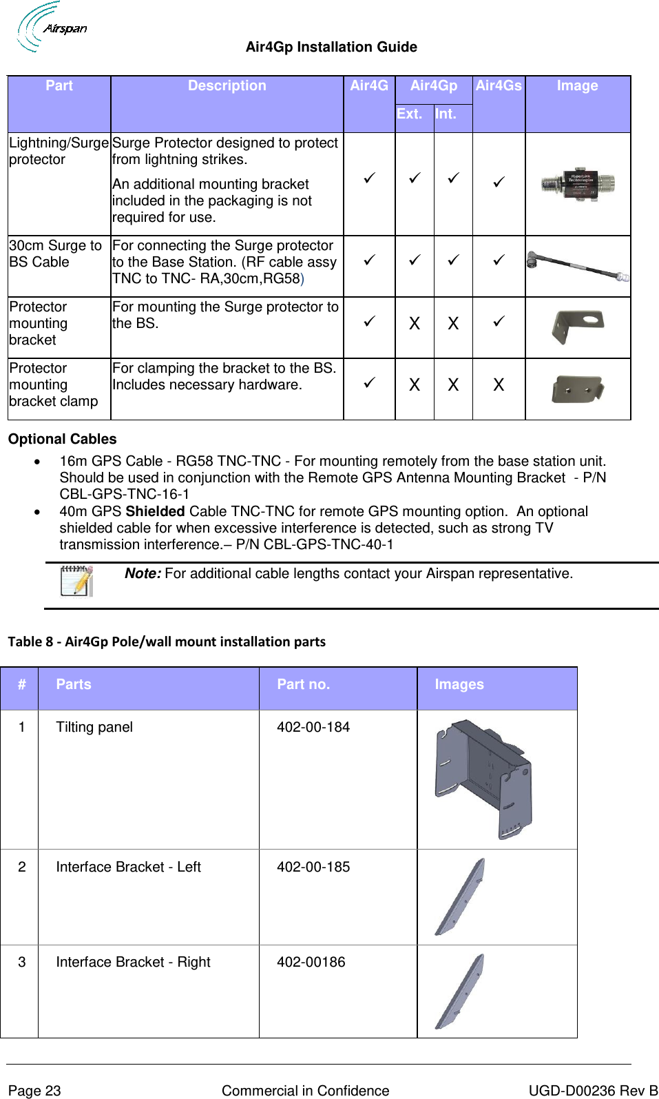
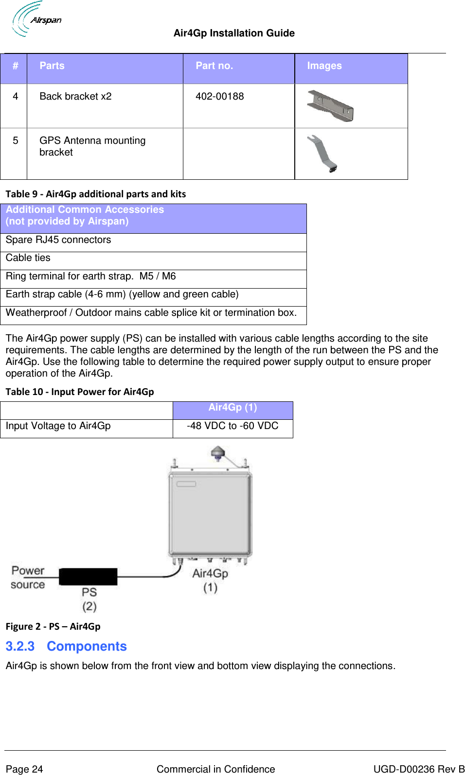
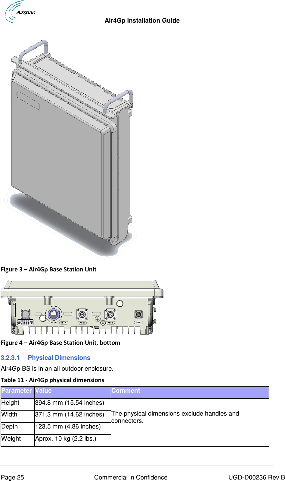
![Air4Gp Installation Guide Page 17 Commercial in Confidence UGD-D00236 Rev B Appendixes [Securing & Connecting the cable, Glossary of Terms, Contact information and Revision history]](https://usermanual.wiki/Airspan-Networks/MMAX5725/User-Guide-1820223-Page-17.png)