Alcatel Lucent Deutschland CMCOB41AC2X6 9764 Compact Metro Cell Outdoor B41 2x6W User Manual Hardware Installation Manual
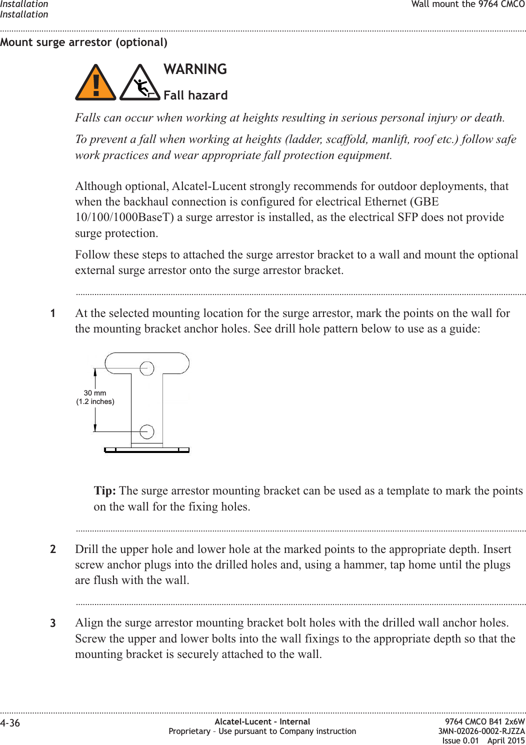
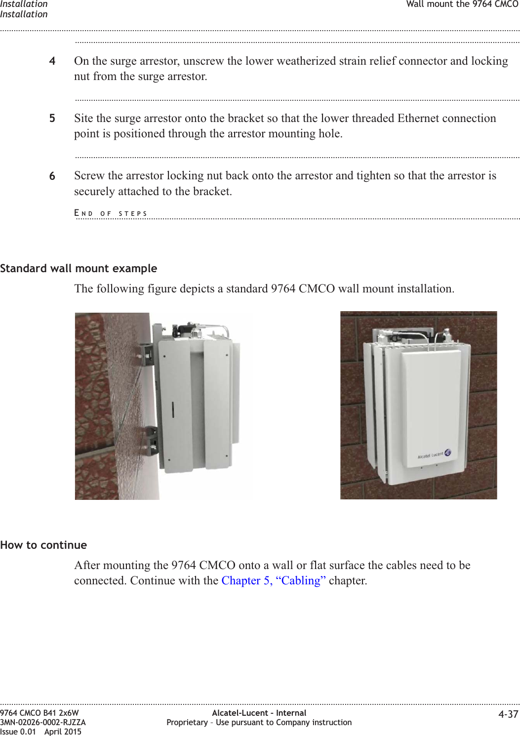
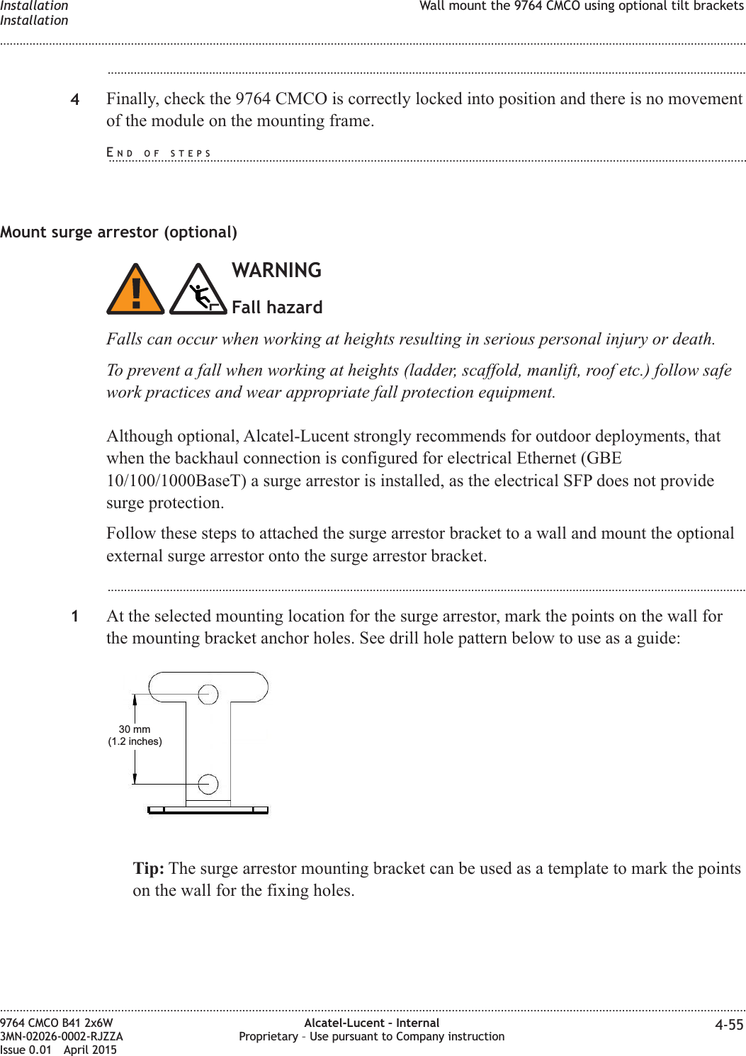
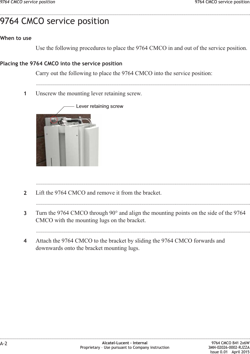
Alcatel-Lucent Deutschland AG 9764 Compact Metro Cell Outdoor B41 2x6W Hardware Installation Manual
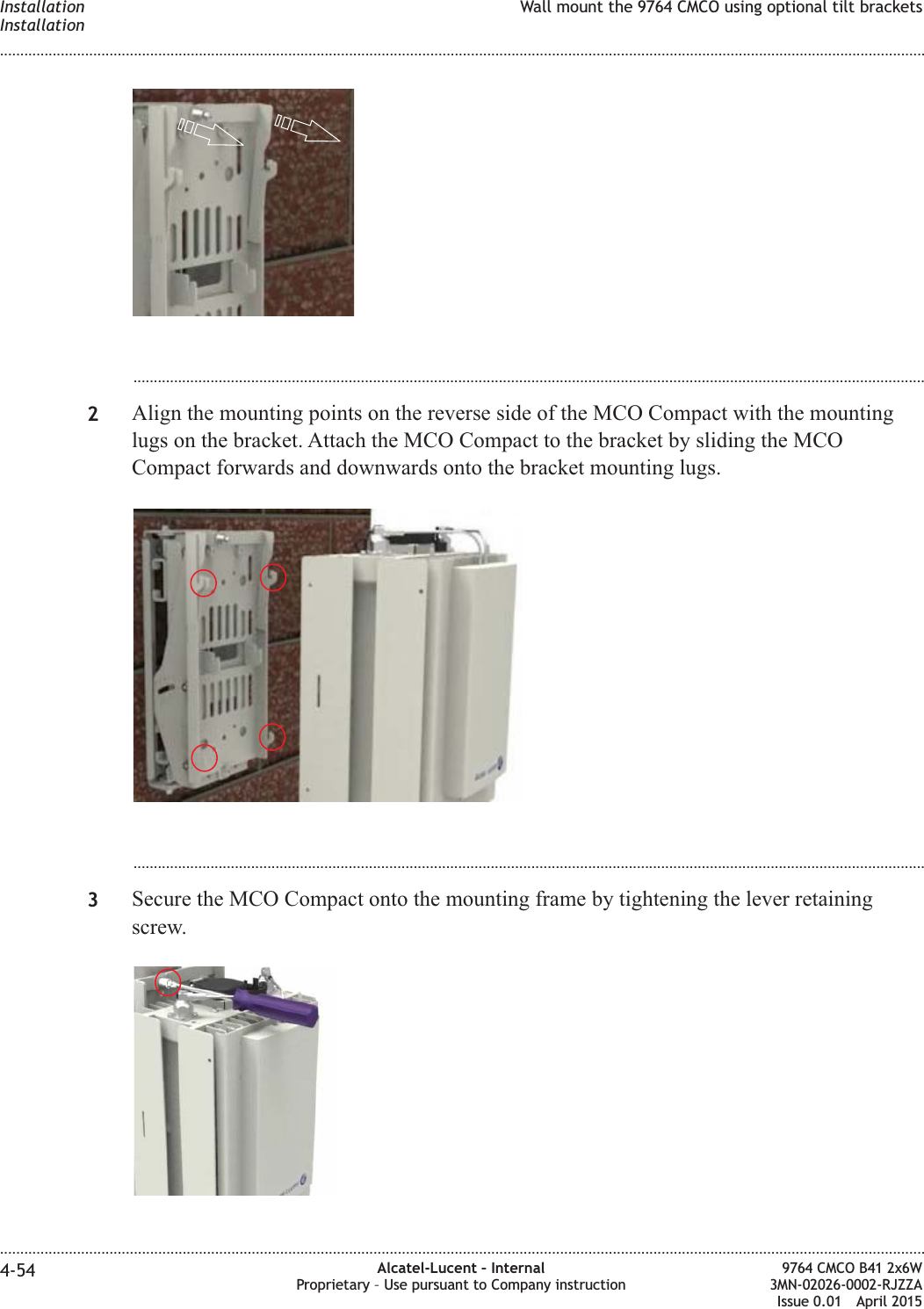
Contents
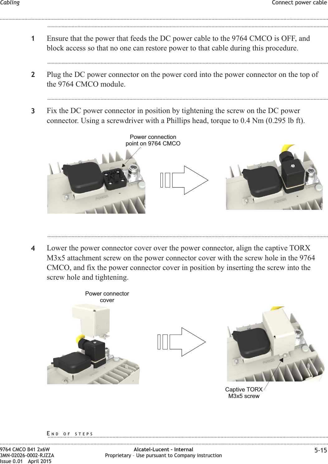
- 1. Hardware Installation Manual
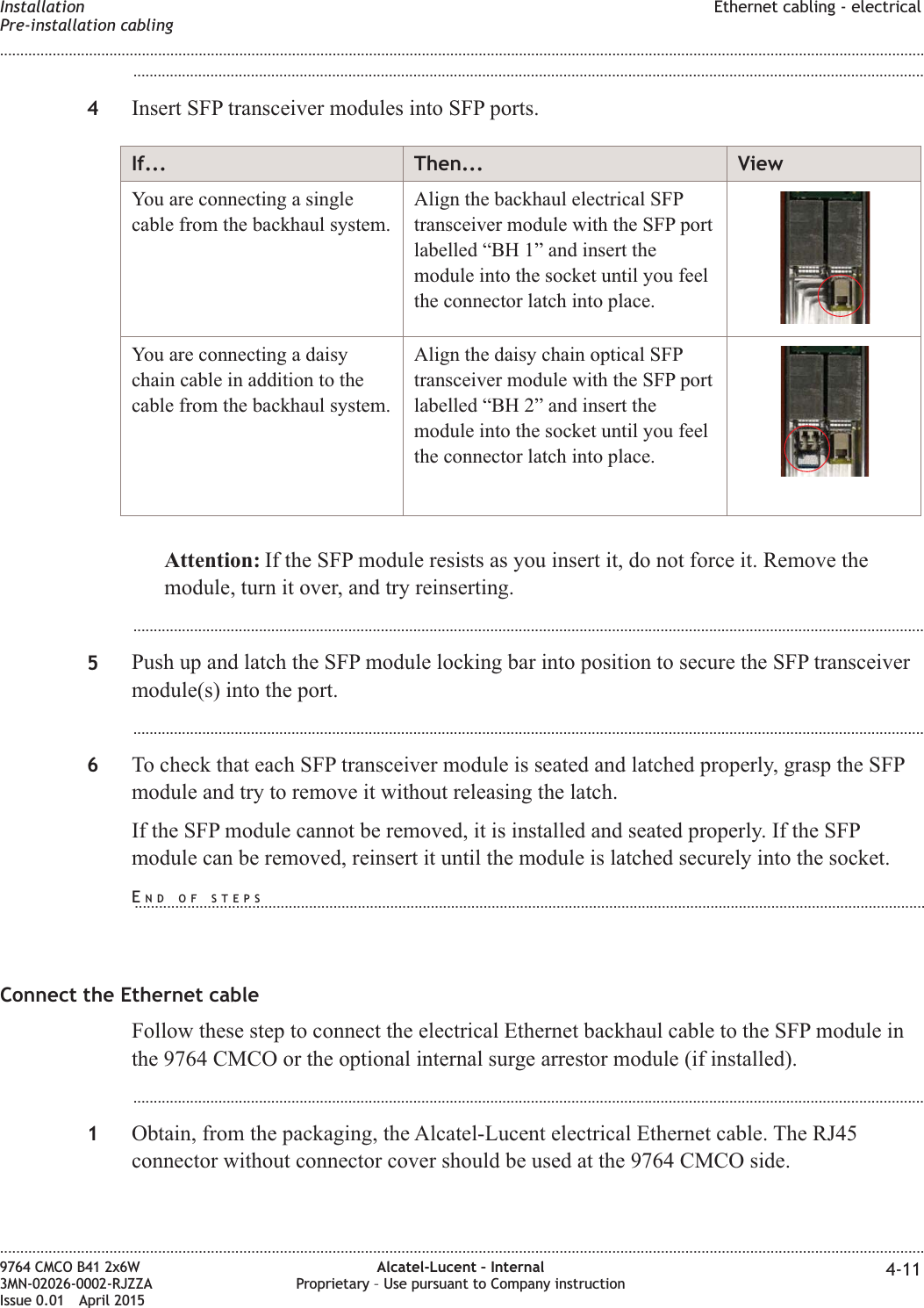
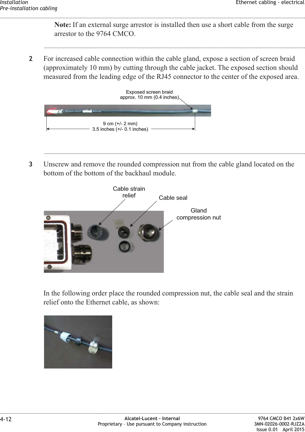
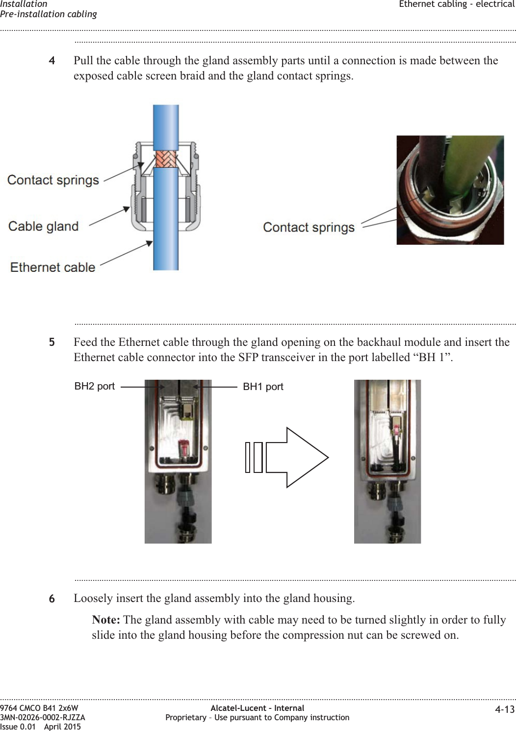
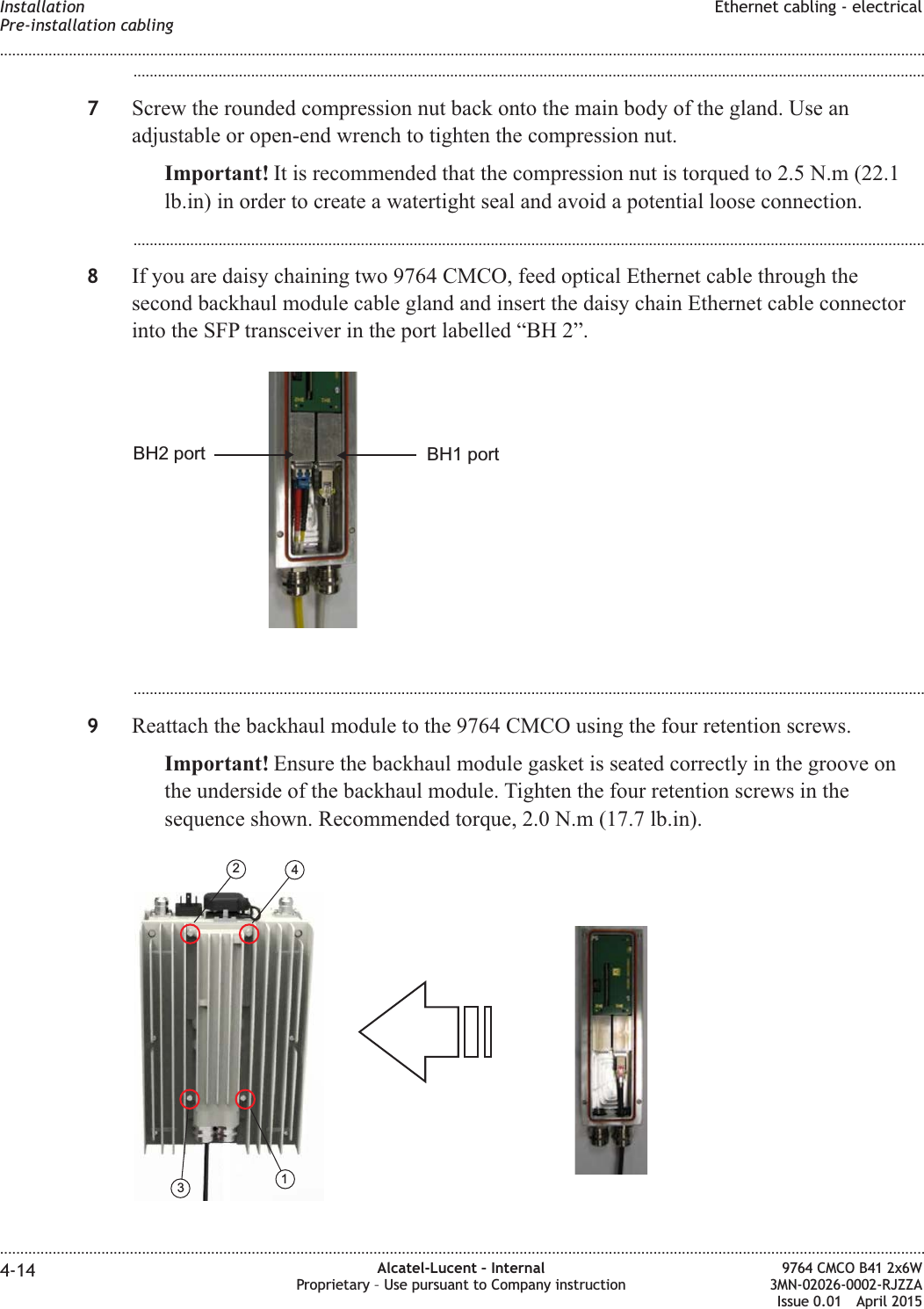
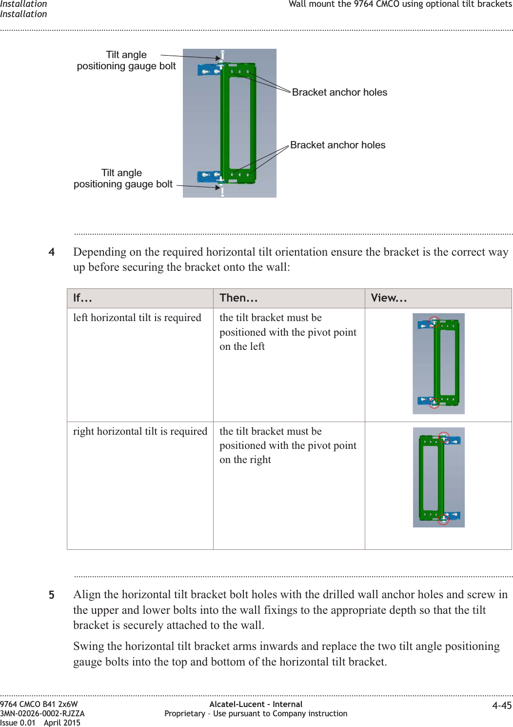
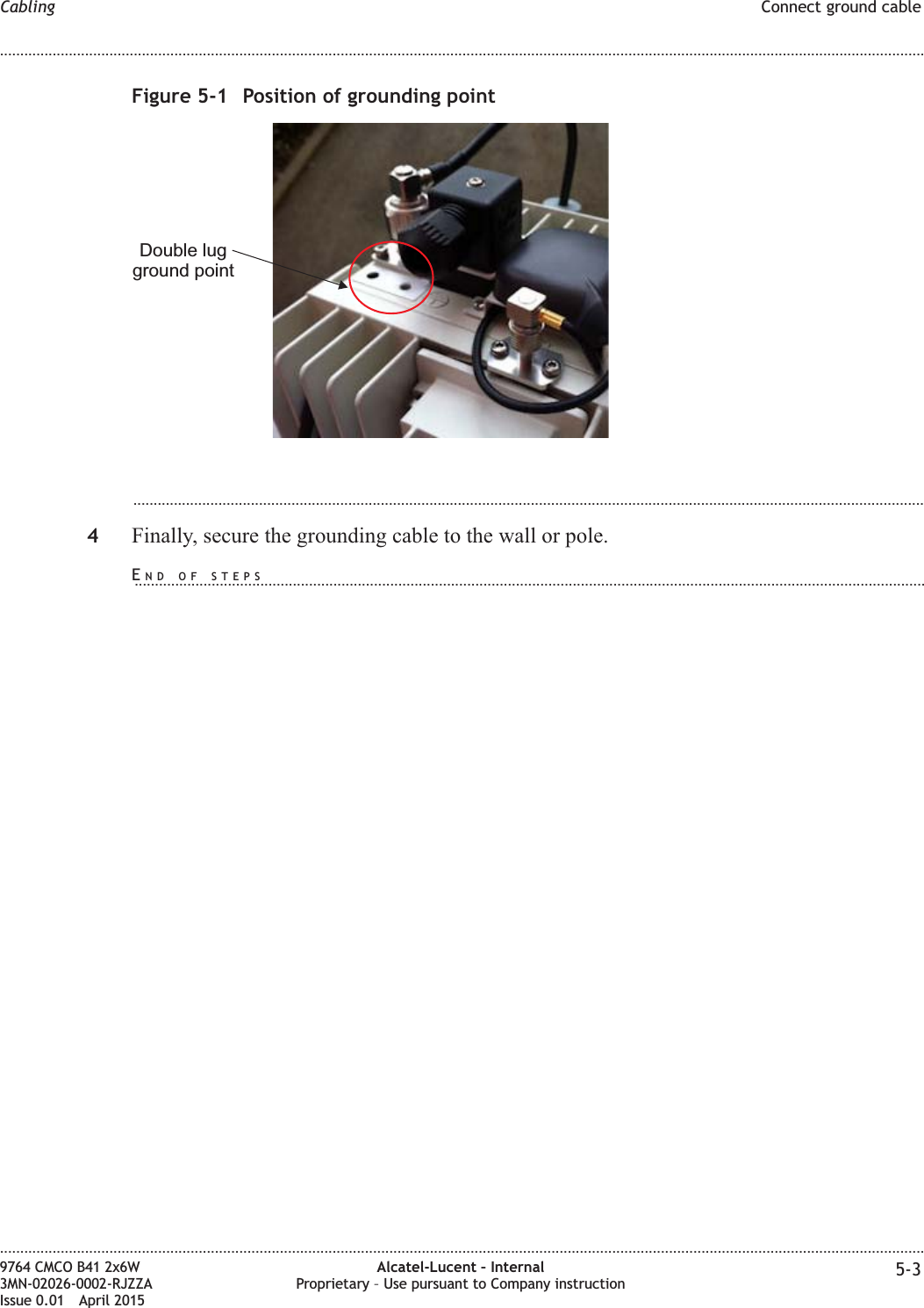
- 2. Site Preparation Manual
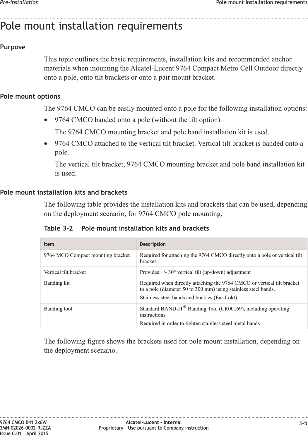
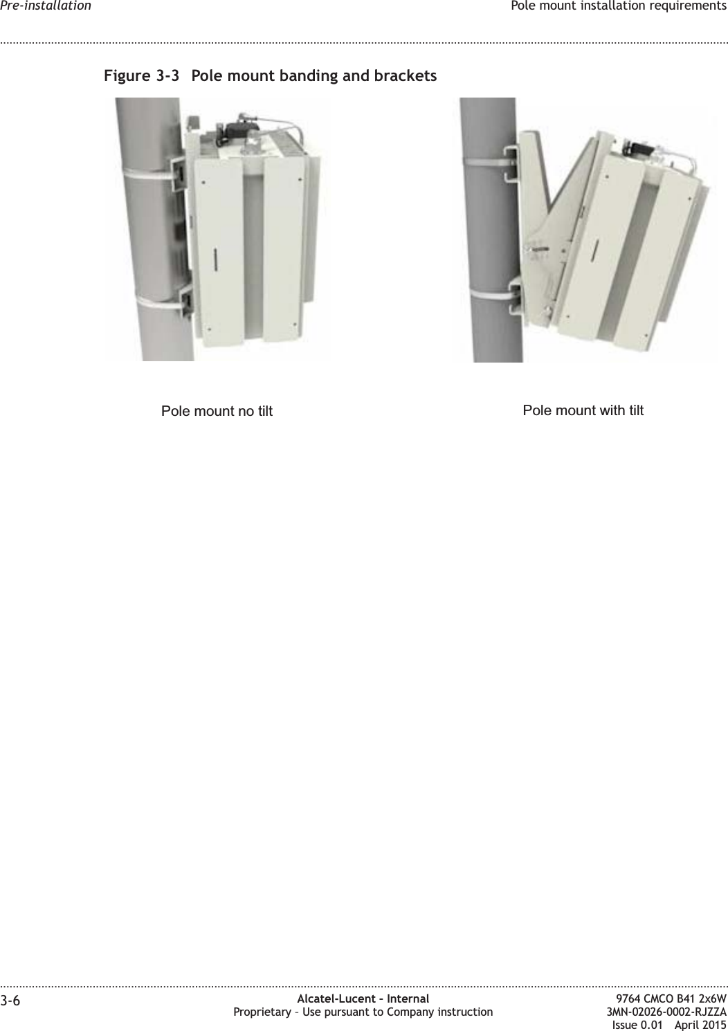
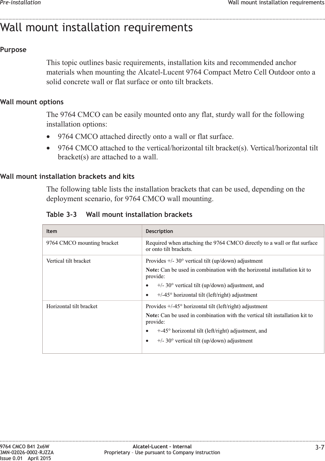
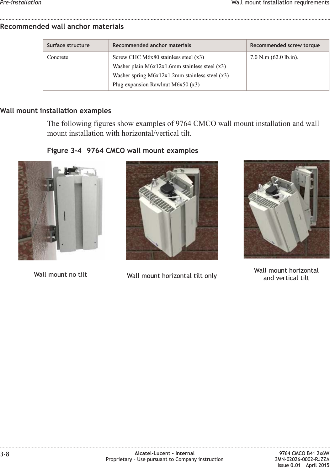
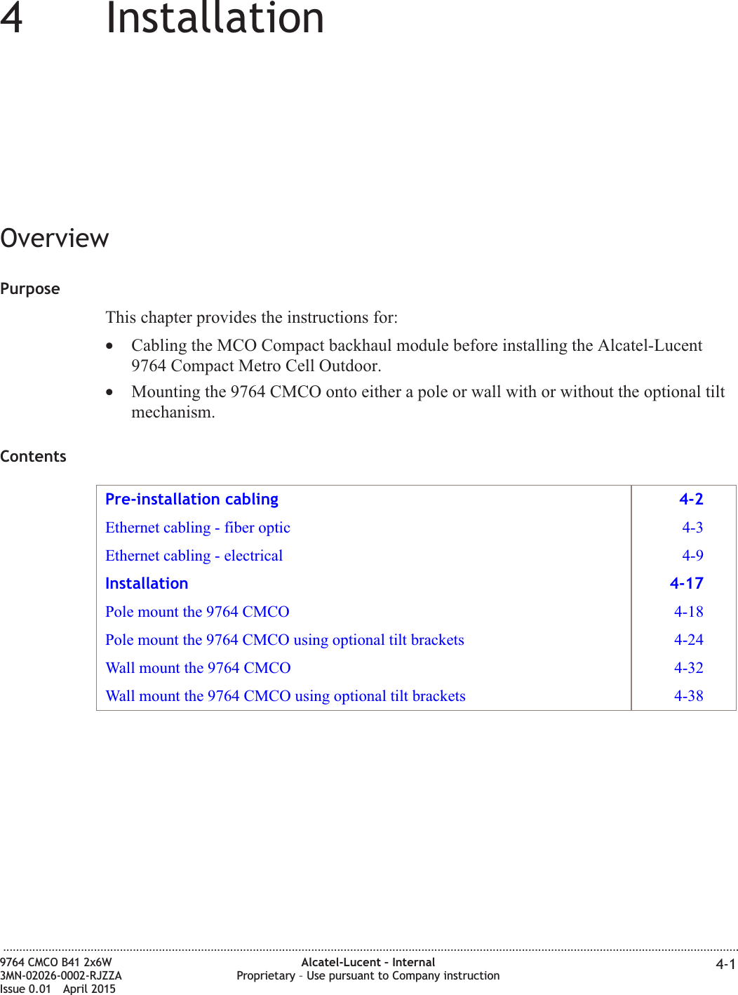
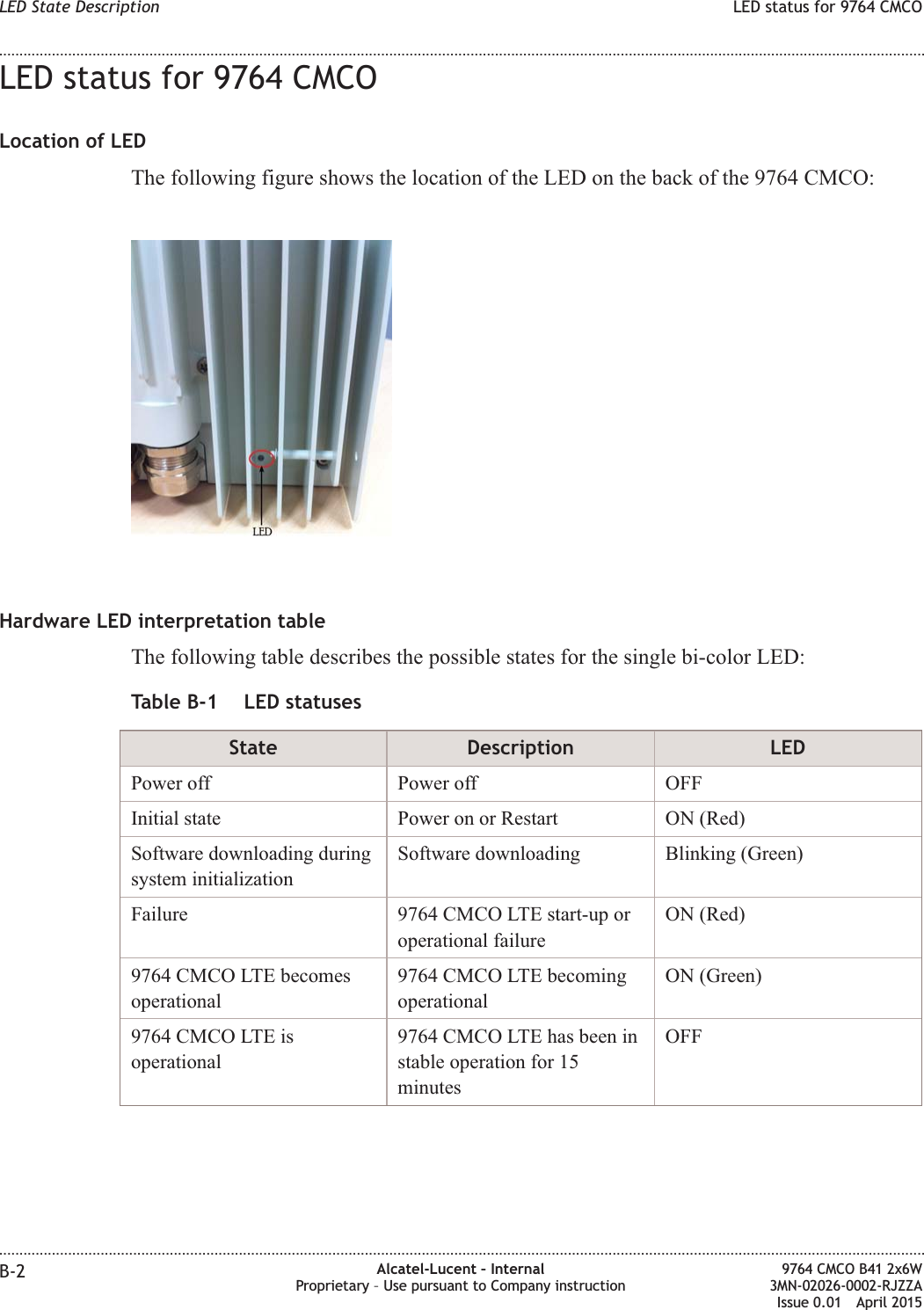
Hardware Installation Manual

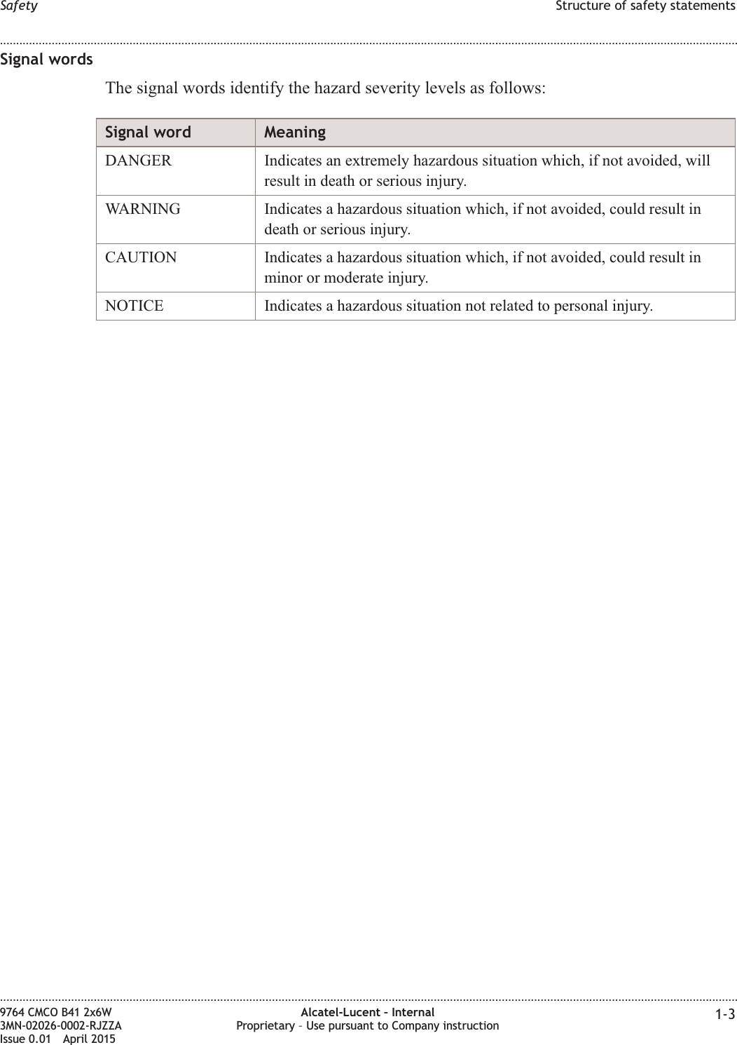
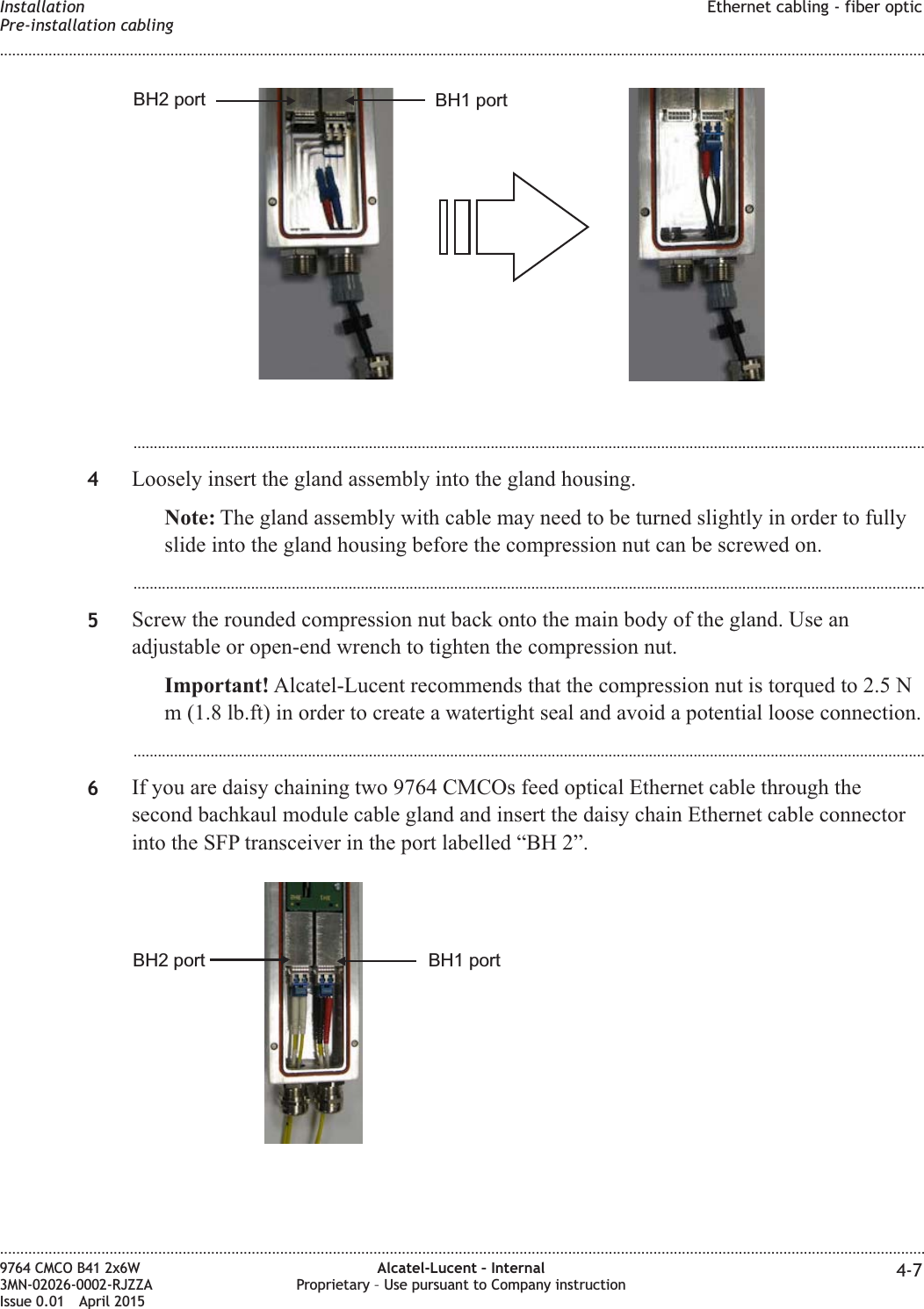
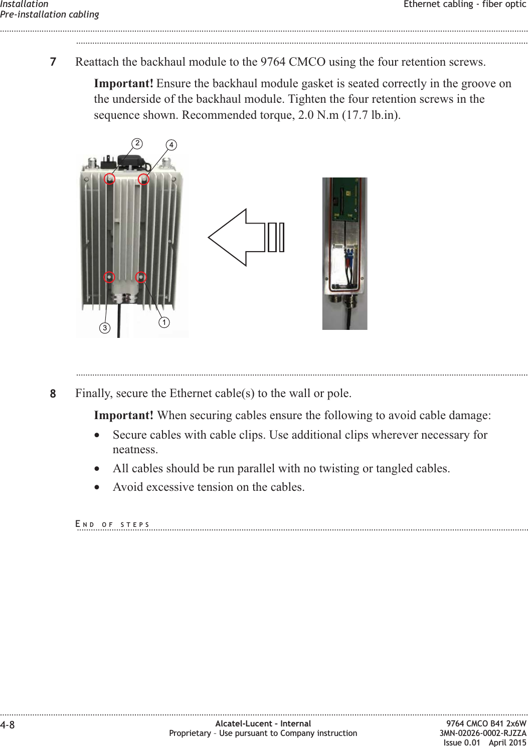
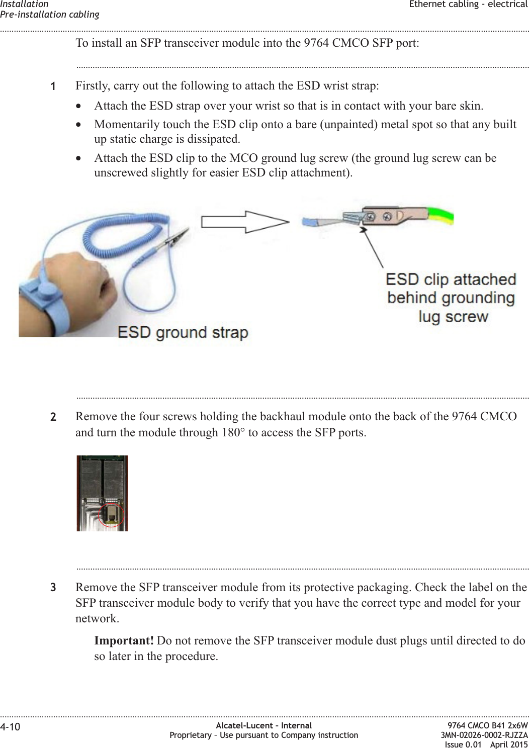
![Structure of safety statementsOverviewThis topic describes the components of safety statements that appear in this document.General structureSafety statements include the following structural elements:Item Structure element Purpose1 Safety alert symbol Indicates the potential for personal injury(optional)2 Safety symbol Indicates hazard type (optional)3 Signal word Indicates the severity of the hazard4 Hazard type Describes the source of the risk of damage orinjury5 Safety message Consequences if protective measures fail6 Avoidance message Protective measures to take to avoid the hazard7 Identifier The reference ID of the safety statement(optional)SAMPLELifting this equipment by yourself can result in injurydue to the size and weight of the equipment.Always use three people or a lifting device to transportand position this equipment. [ABC123]CAUTIONLifting hazardSafety Structure of safety statements........................................................................................................................................................................................................................................................................................................................................................................................................................................................................1-2 Alcatel-Lucent – InternalProprietary – Use pursuant to Company instruction9764 CMCO B41 2x6W3MN-02026-0002-RJZZAIssue 0.01 April 2015PRELIMINARYPRELIMINARY](https://usermanual.wiki/Alcatel-Lucent-Deutschland/CMCOB41AC2X6.Hardware-Installation-Manual/User-Guide-2663918-Page-18.png)
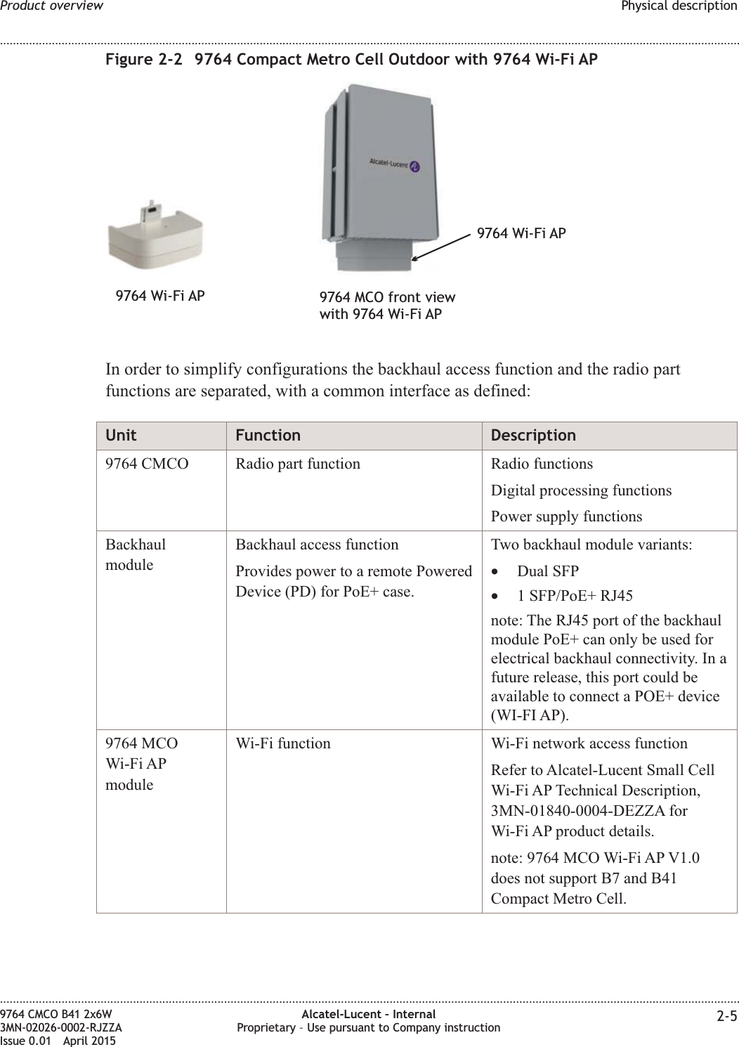
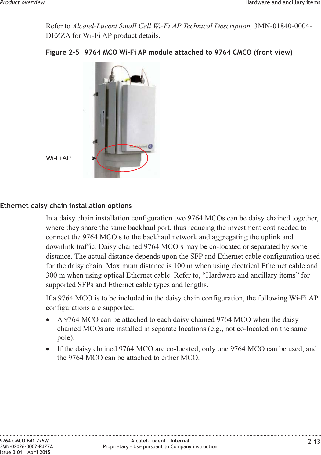
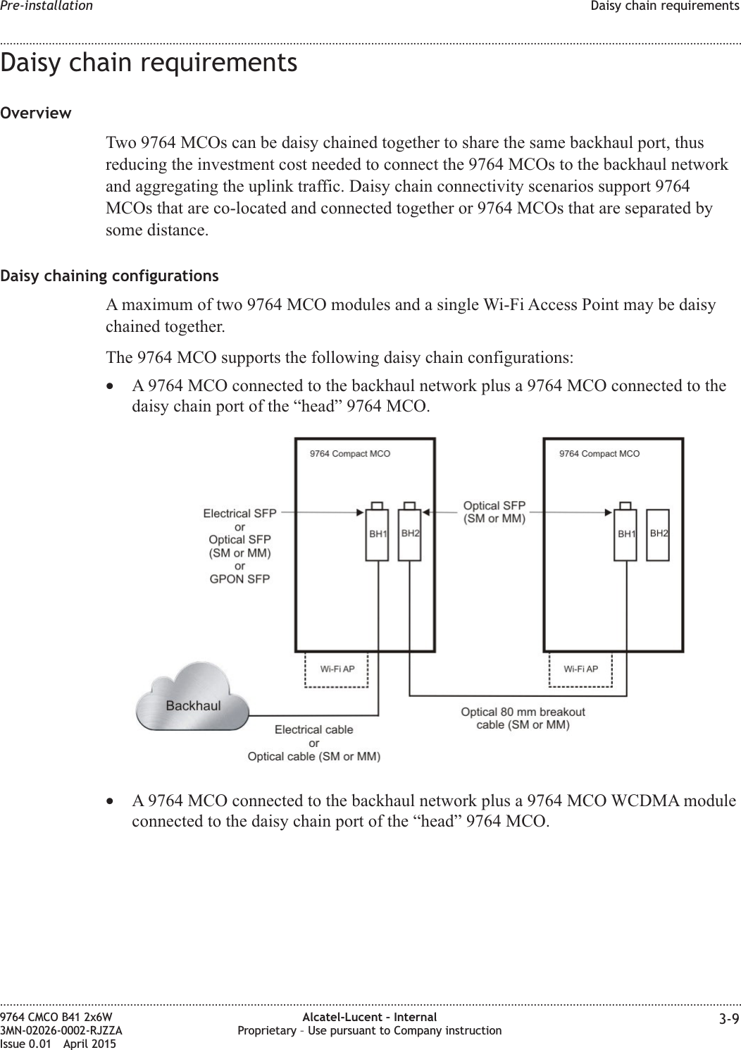
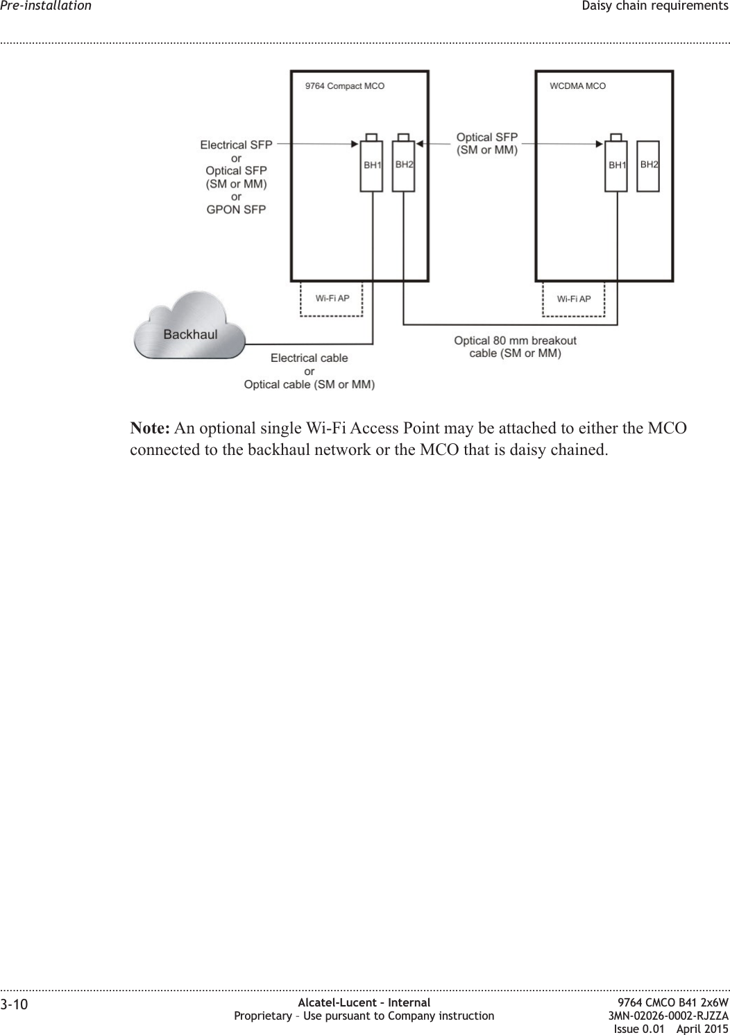
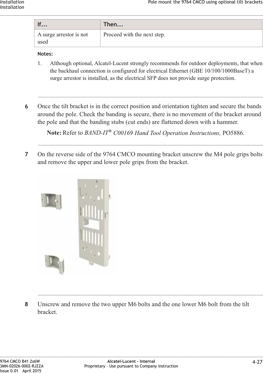
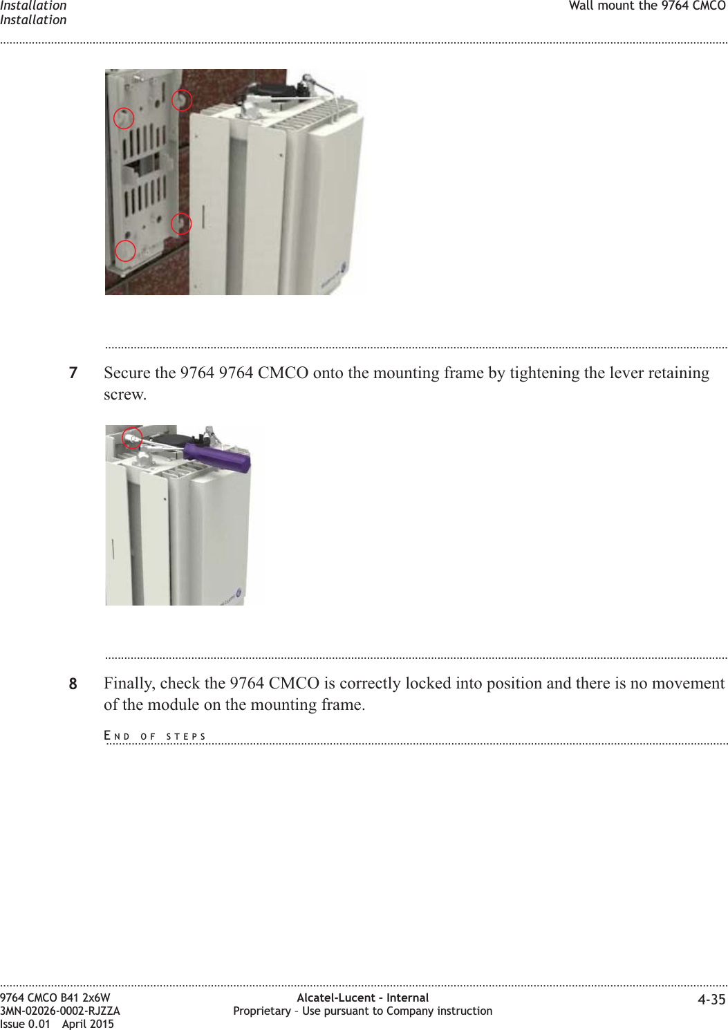

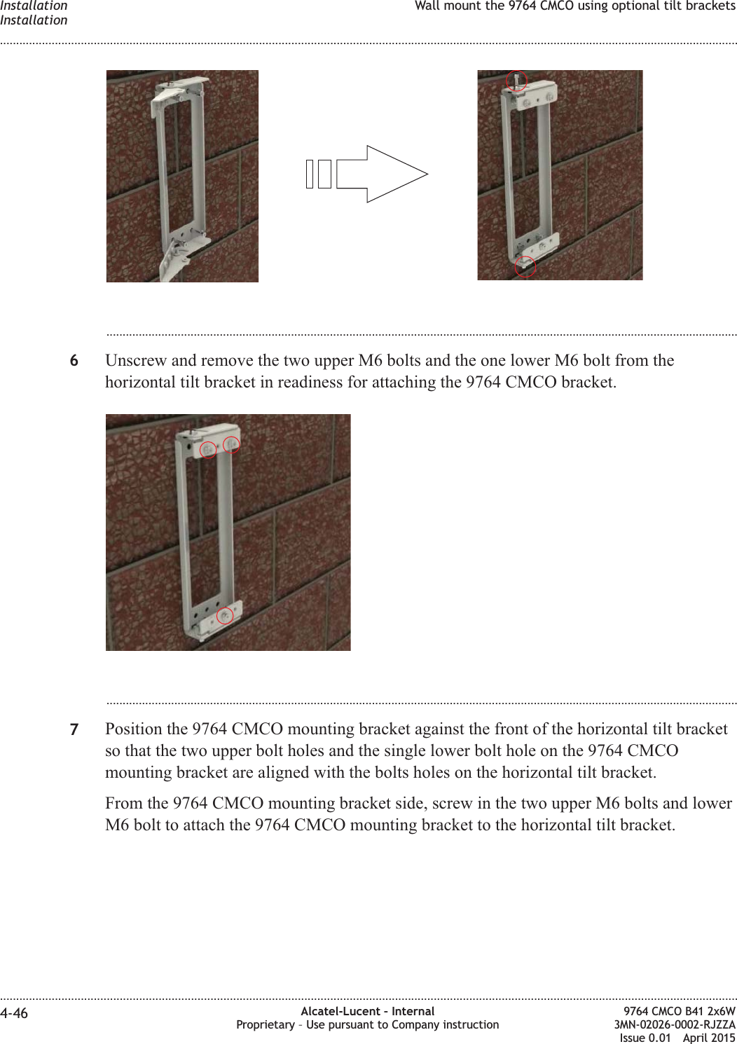


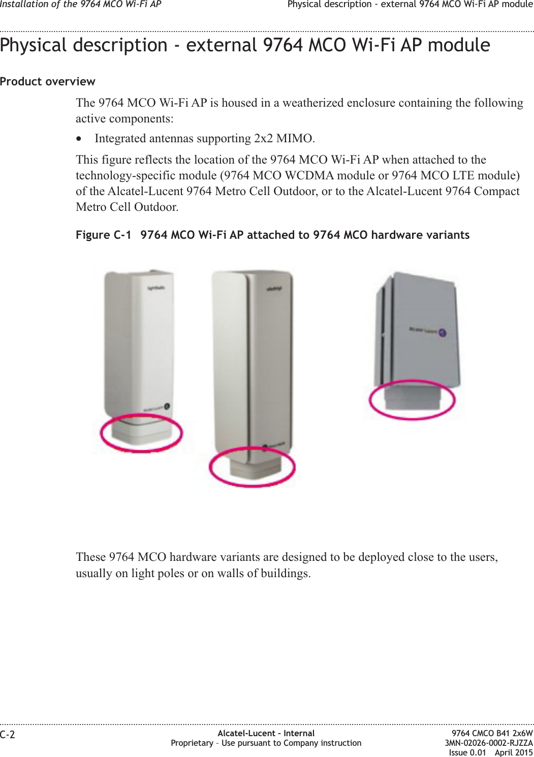
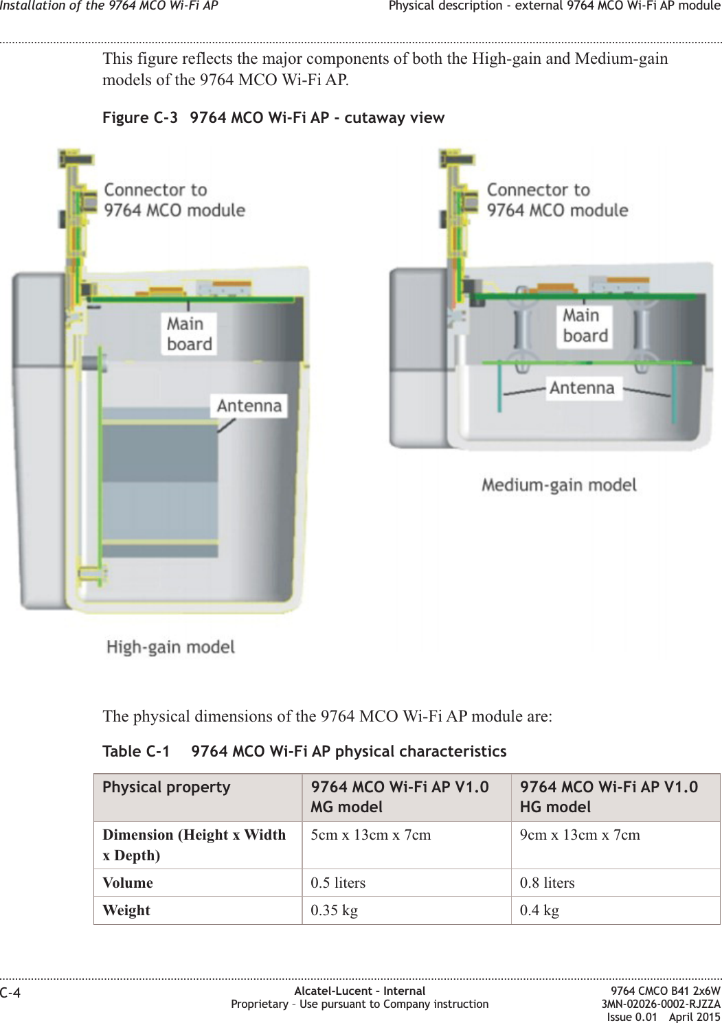
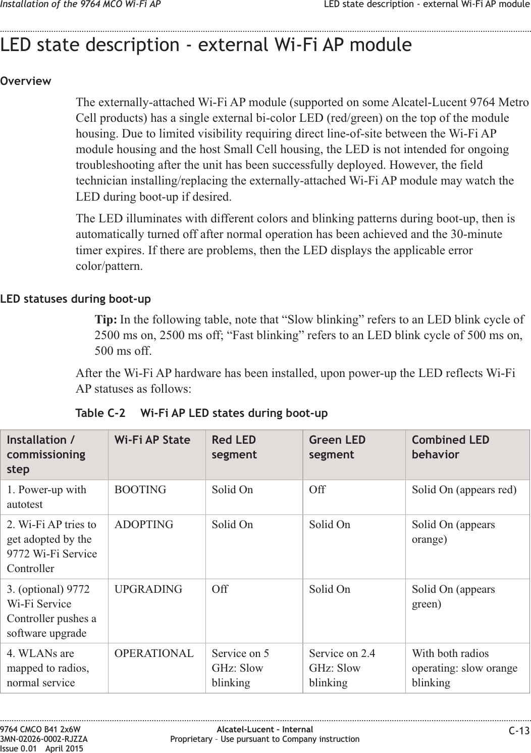
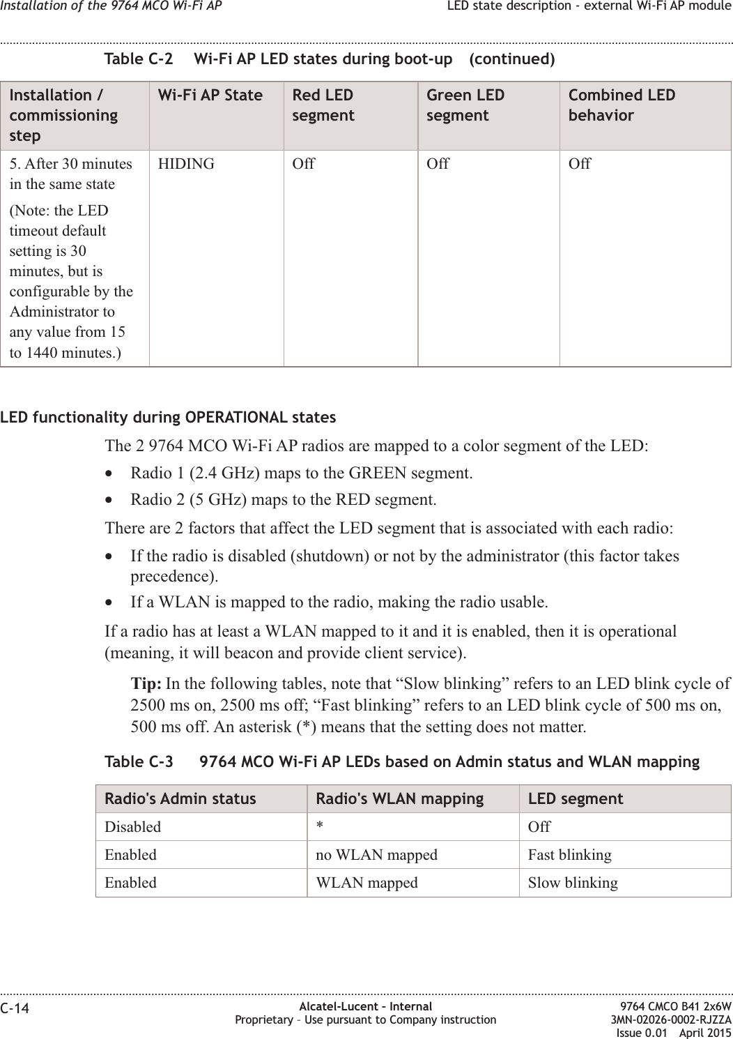
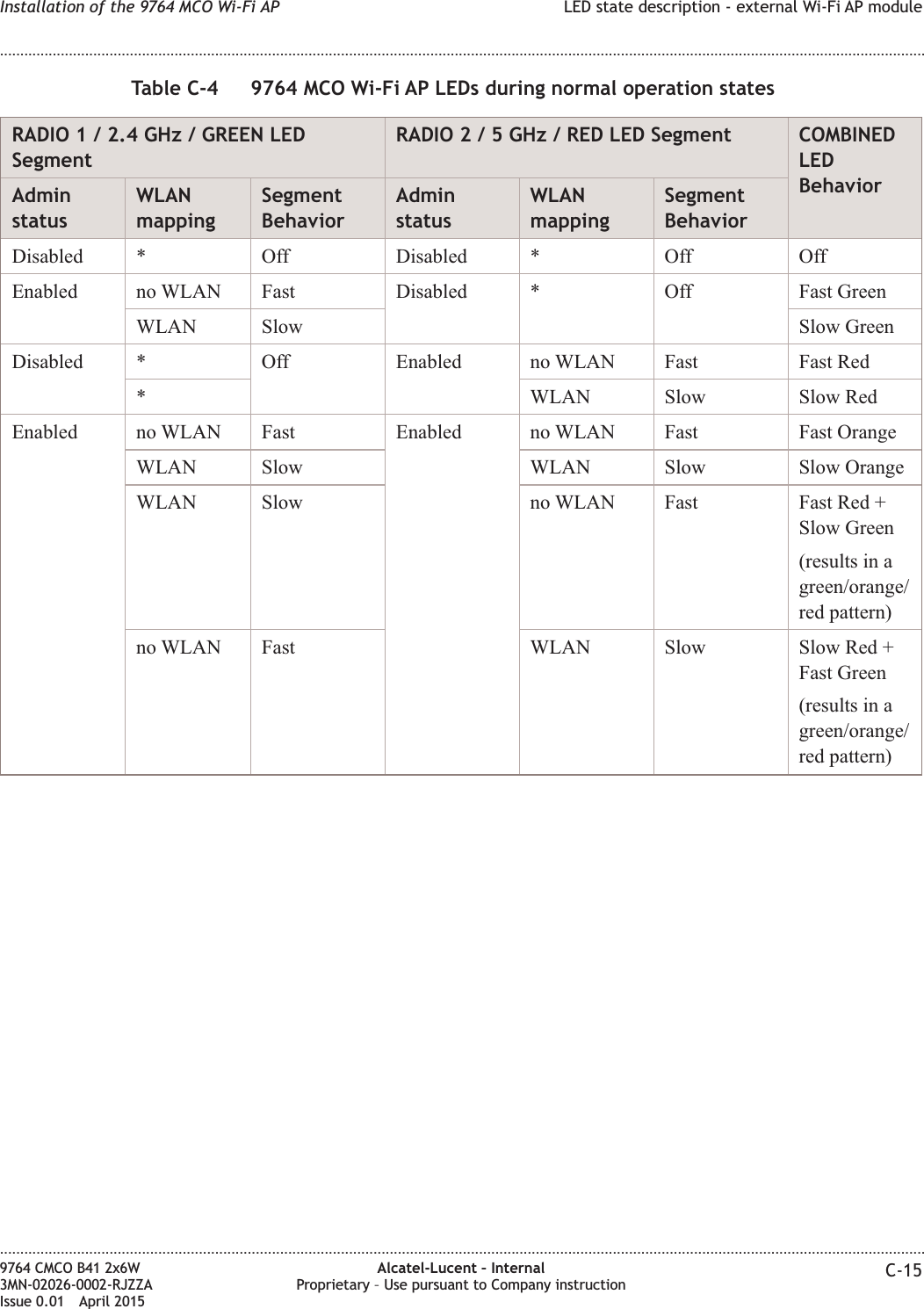
![This figure reflects the available 9764 MCO Wi-Fi AP models (9764 Metro Cell OutdoorWi-Fi AP V1.0 HG [high gain] and 9764 Metro Cell Outdoor Wi-Fi AP V1.0 MG[medium gain]).Figure C-2 9764 MCO Wi-Fi AP - closed housingInstallation of the 9764 MCO Wi-Fi AP Physical description - external 9764 MCO Wi-Fi AP module........................................................................................................................................................................................................................................................................................................................................................................................................................................................................9764 CMCO B41 2x6W3MN-02026-0002-RJZZAIssue 0.01 April 2015Alcatel-Lucent – InternalProprietary – Use pursuant to Company instruction C-3PRELIMINARYPRELIMINARY](https://usermanual.wiki/Alcatel-Lucent-Deutschland/CMCOB41AC2X6.Hardware-Installation-Manual/User-Guide-2663918-Page-141.png)