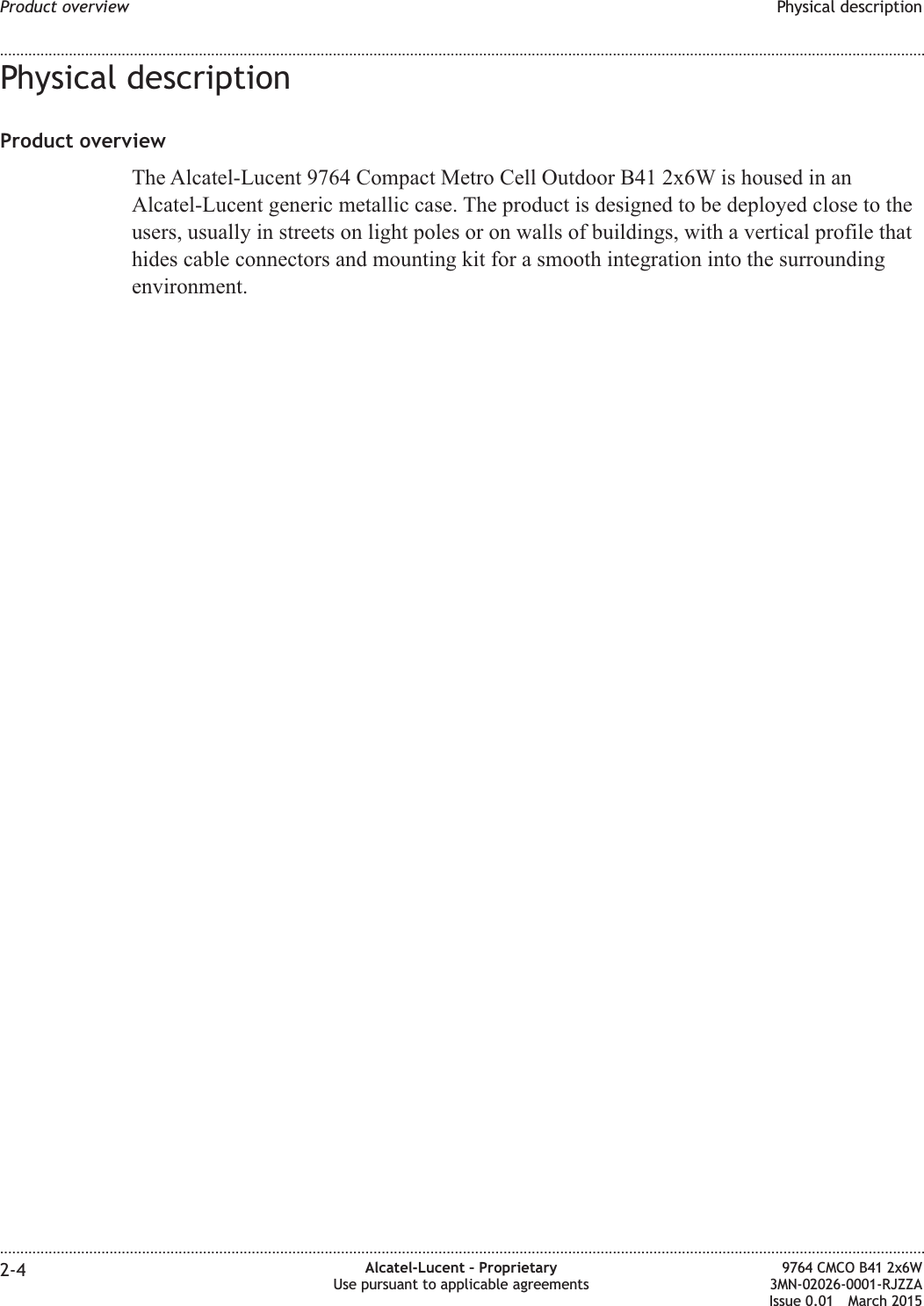
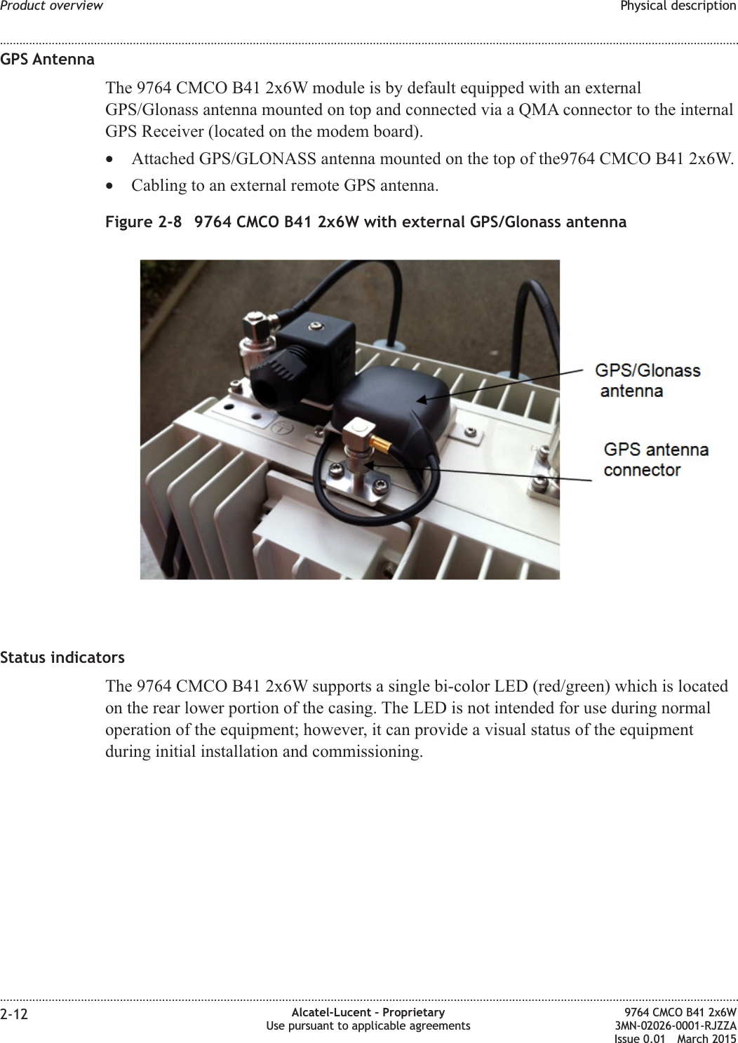
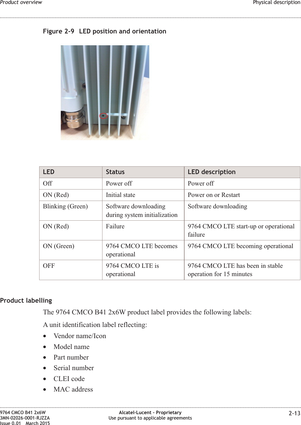
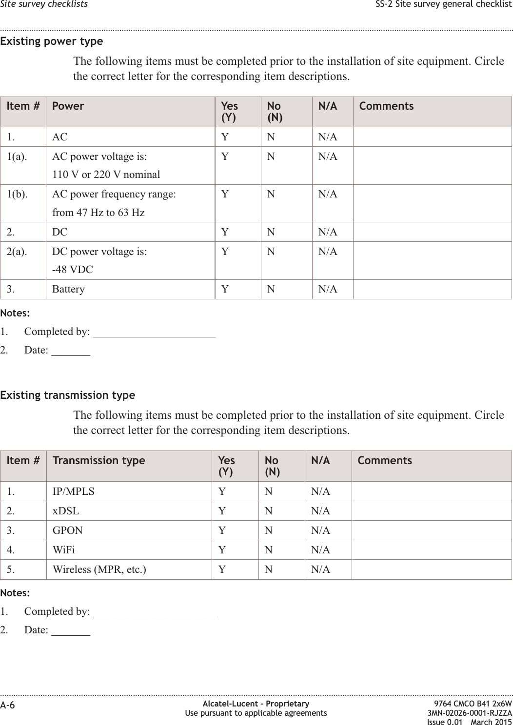
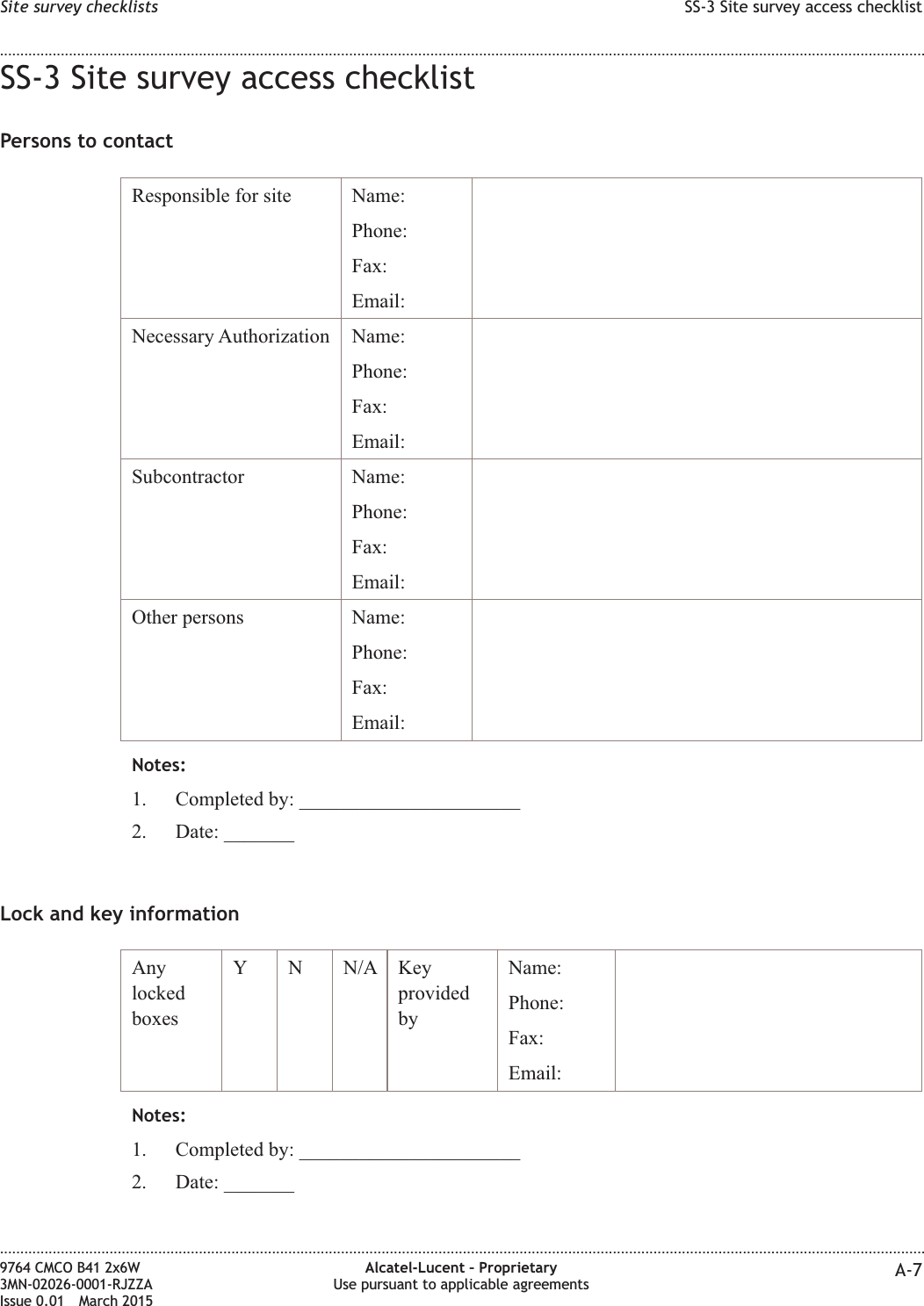
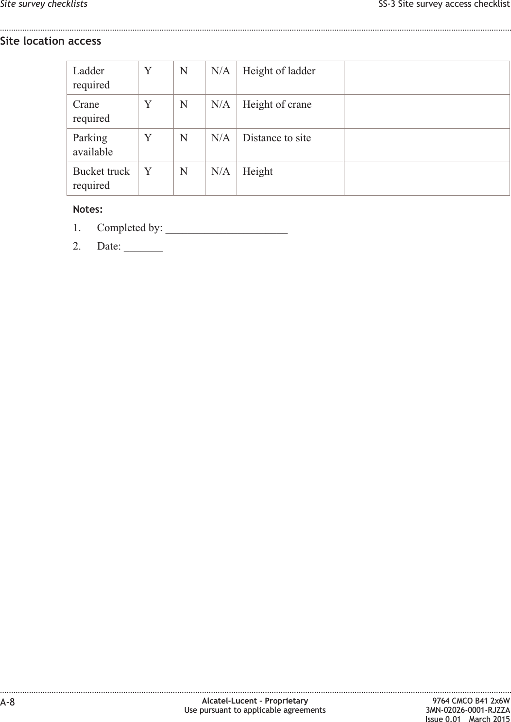
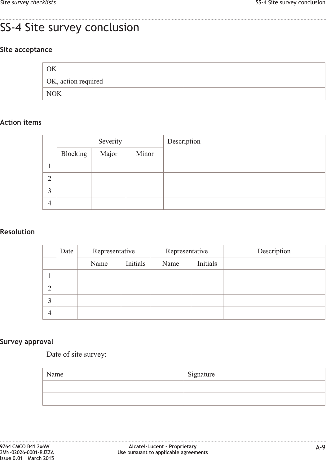
Alcatel Lucent Deutschland CMCOB41AC2X6 9764 Compact Metro Cell Outdoor B41 2x6W User Manual Site Preparation Manual
Alcatel-Lucent Deutschland AG 9764 Compact Metro Cell Outdoor B41 2x6W Site Preparation Manual
Contents
- 1. Hardware Installation Manual
- 2. Site Preparation Manual
Site Preparation Manual


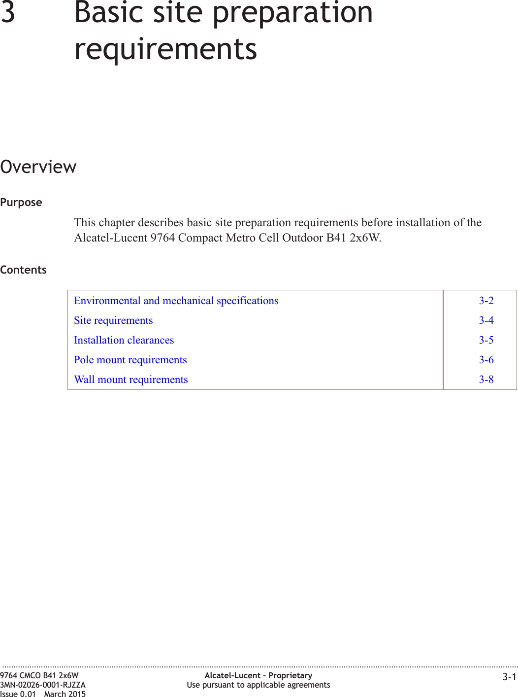
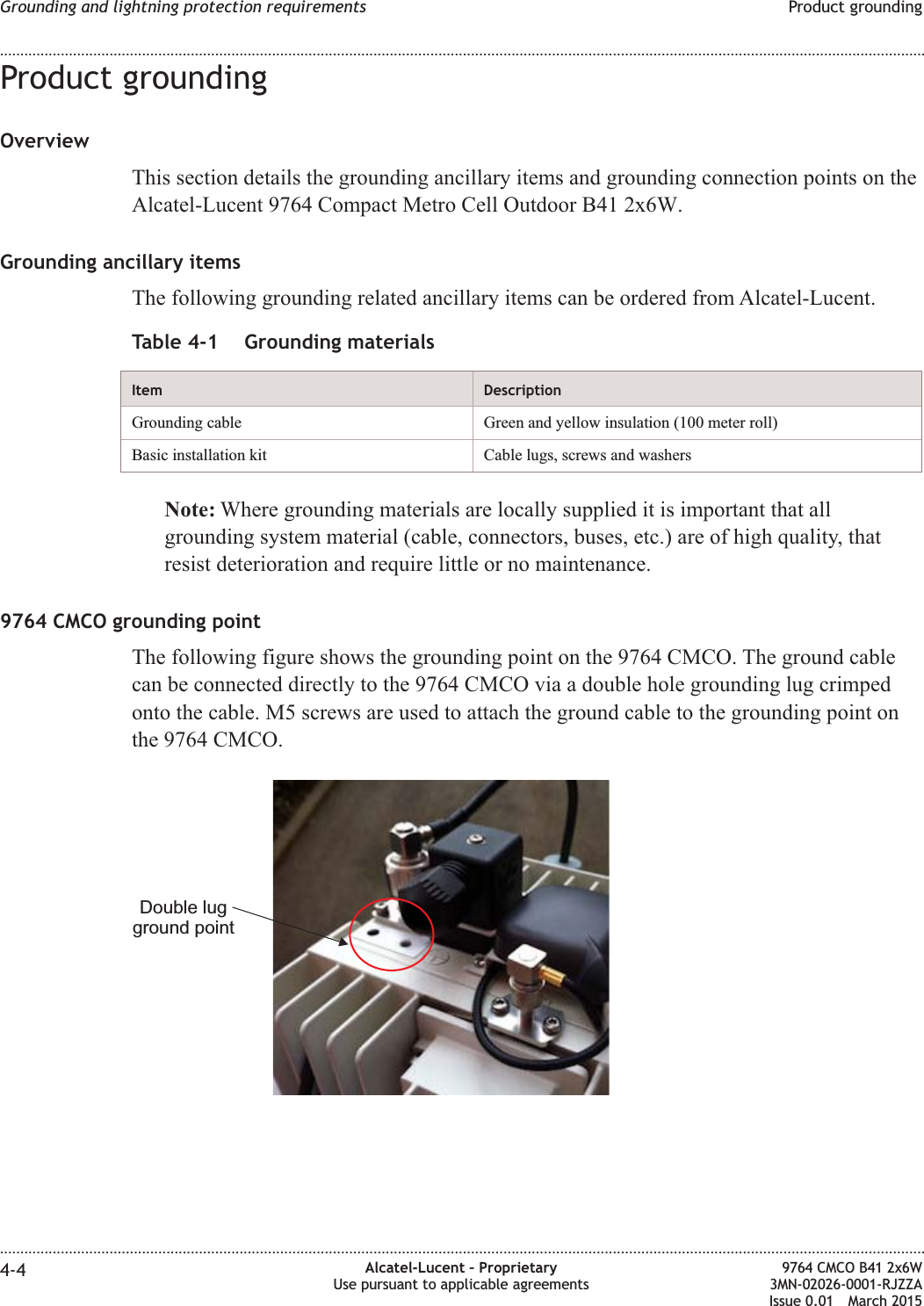
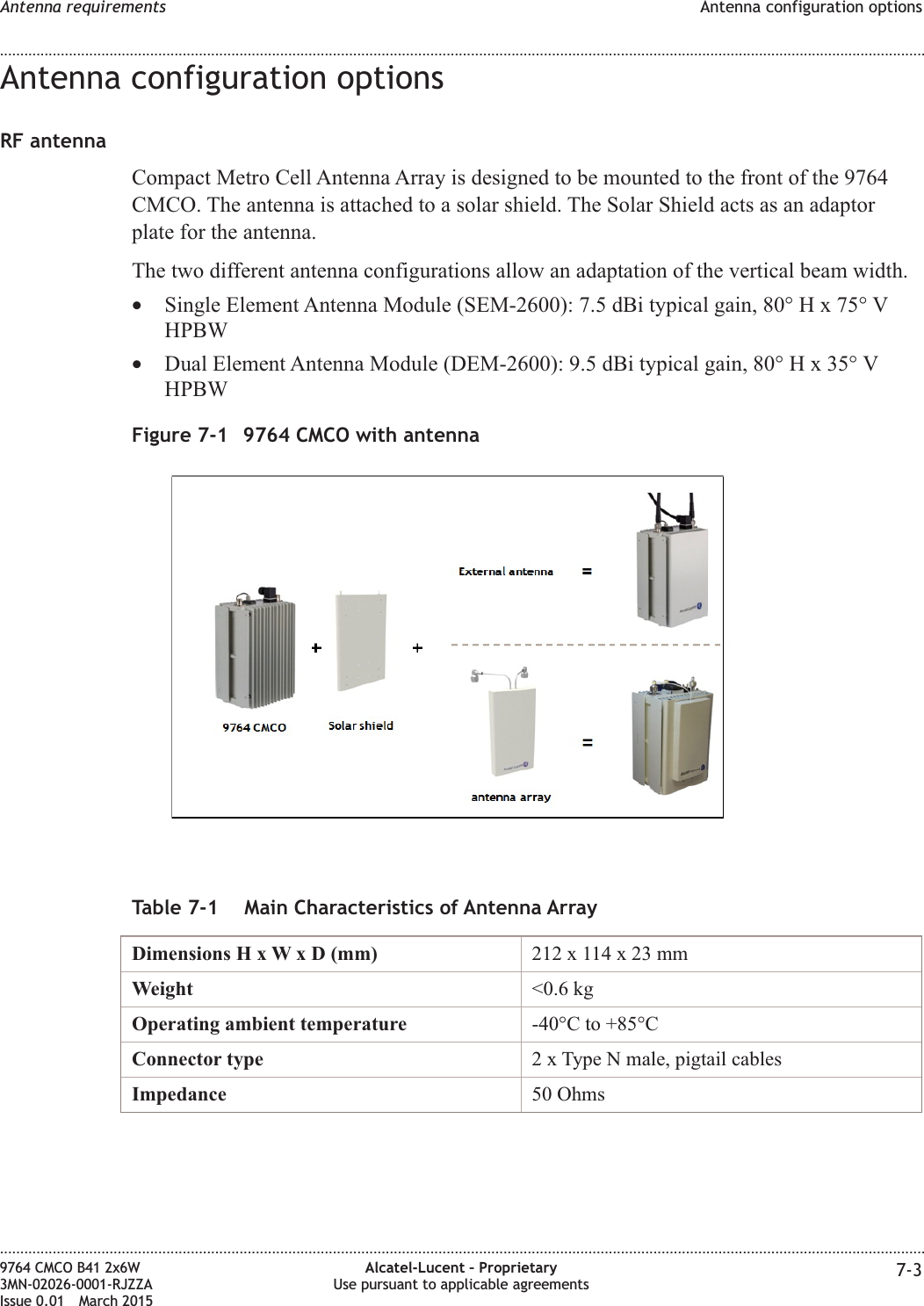
![•Lock Out/Tag Out•Accident/Incident Reporting.Other related training is for:•Integration into the cell site•Operation, Administration, and Maintenance (OA&M).Site preparation checklistsAll site preparation activities, as well as adherence to the guidelines, should be verifiedprior to the installation of the cell site equipment.Various checklists and punchlist sheets have been provided in Appendix A of thisdocument to aid customers and Alcatel-Lucent personnel during a base station siteMethod of Procedure (MOP) walk-through prior to the equipment installation.Utilization of the checklists helps ensure a quality installation and provides a base stationsite history file for later reference. The punchlist sheets are used to track completion ofany outstanding site preparation items, and to aid in the project management ofinstallation resources.Base station configuration sheetsConfiguration sheets are provided in Appendix B of this document to aid the Customer,Equipment Engineering, and Wireless Project Management during the various stages ofproduct deployment. The configuration sheets are used to document the base stationequipment configuration, conditions, and other pertinent information for reference duringproduct deployment, and future additions. The configuration sheets should be completedduring the equipment engineering phase. Reference to this information during MOPwalk-through assists with completion of the site preparation checklists.Document supportFor support in using this or any other Alcatel-Lucent document, contact Alcatel-Lucent atthe following telephone numbers.From United States•If you are using a landline, a cellular phone or VoIP, dial this number: 1-888-582-3688From other countries•If you are using a cellular phone or VoIP, dial this number: +1-630-224-2485•If you are using a landline (phone without a plus [+] character), replace the plus signwith your country's exit code. Dial this number: Exit code for the country of origin:1-630-224-2485. See the country-specific exit codes listed here.These numbers apply for document support only. Please see the section “Technicalsupport” for details about product hardware, software, and technical support.About this document........................................................................................................................................................................................................................................................................................................................................................................................................................................................................9764 CMCO B41 2x6W3MN-02026-0001-RJZZAIssue 0.01 March 2015Alcatel-Lucent – ProprietaryUse pursuant to applicable agreements xvDRAFTDRAFT](https://usermanual.wiki/Alcatel-Lucent-Deutschland/CMCOB41AC2X6.Site-Preparation-Manual/User-Guide-2663919-Page-15.png)
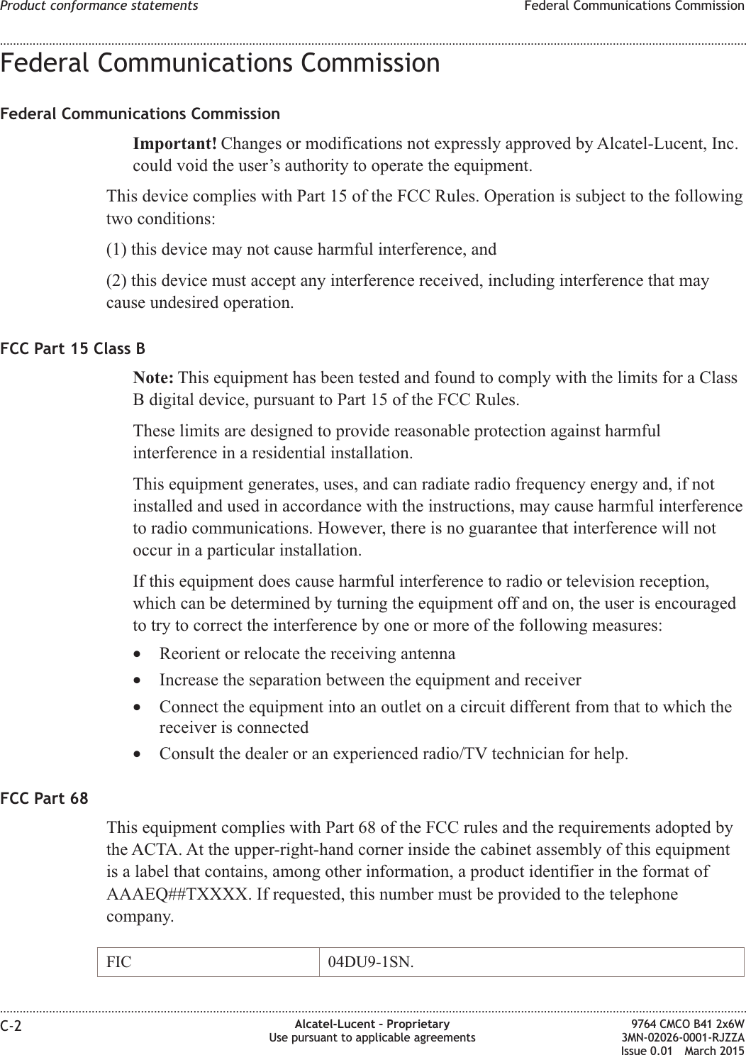
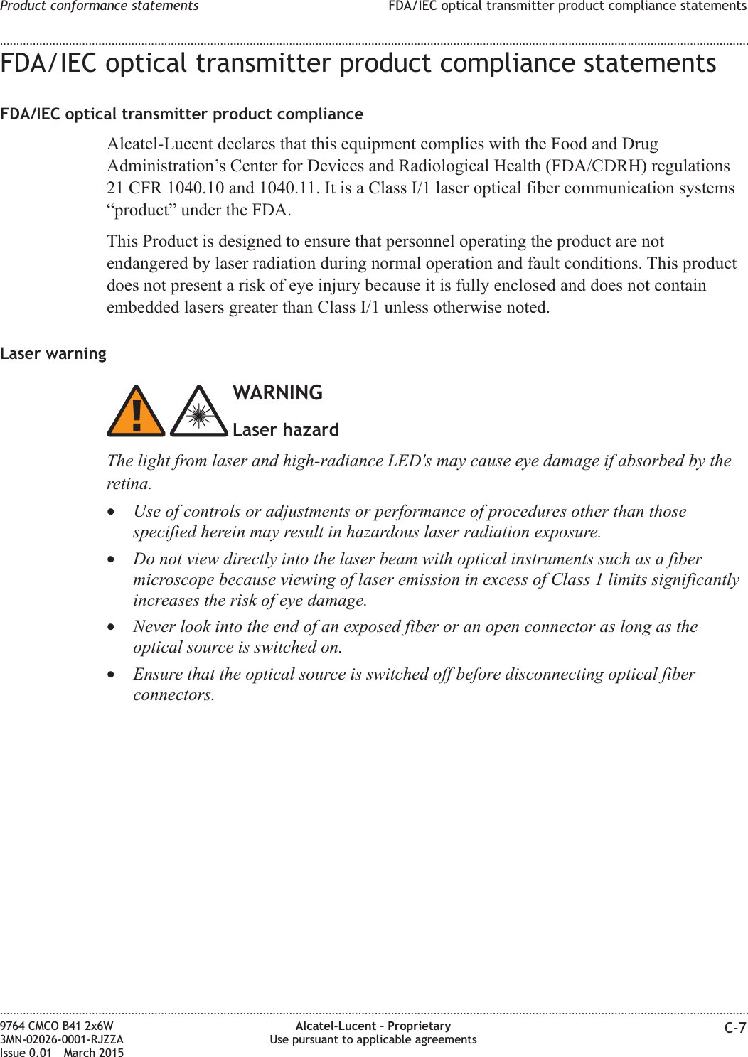
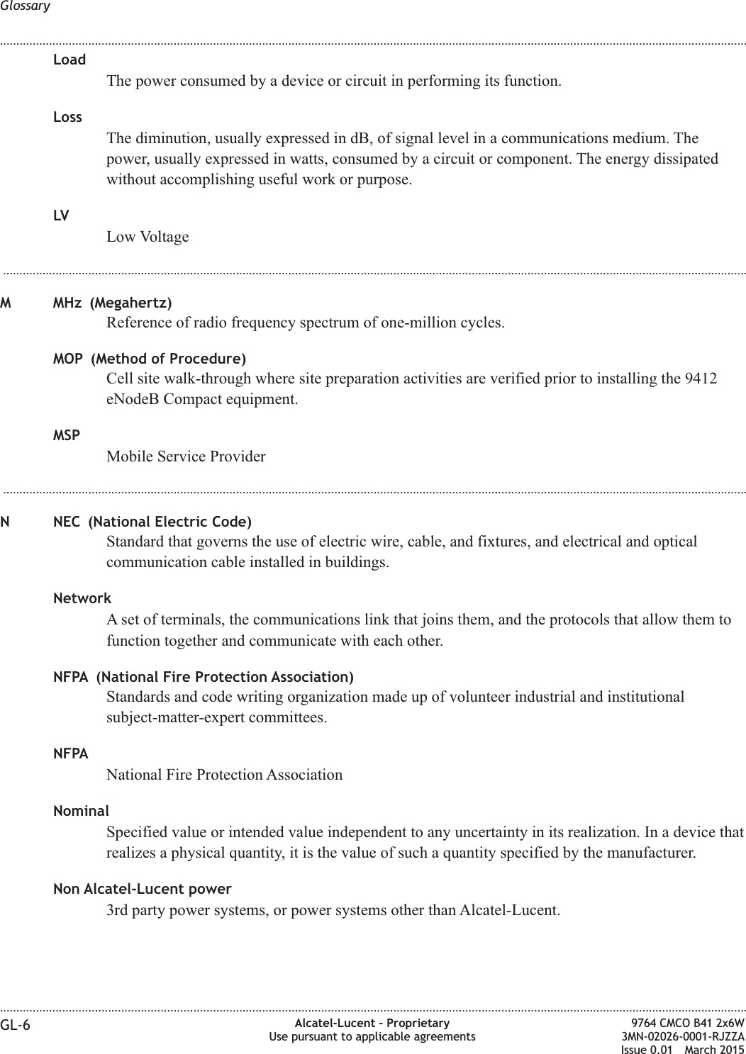
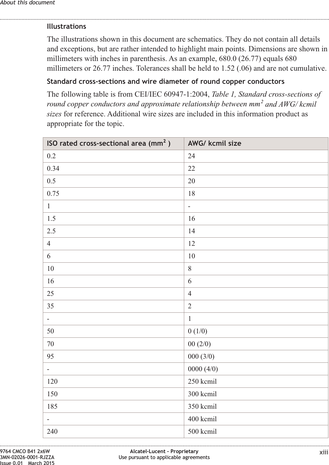
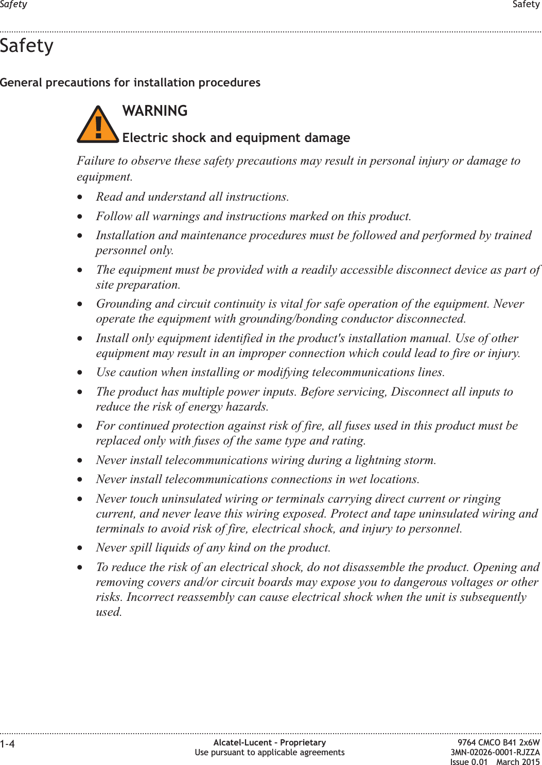
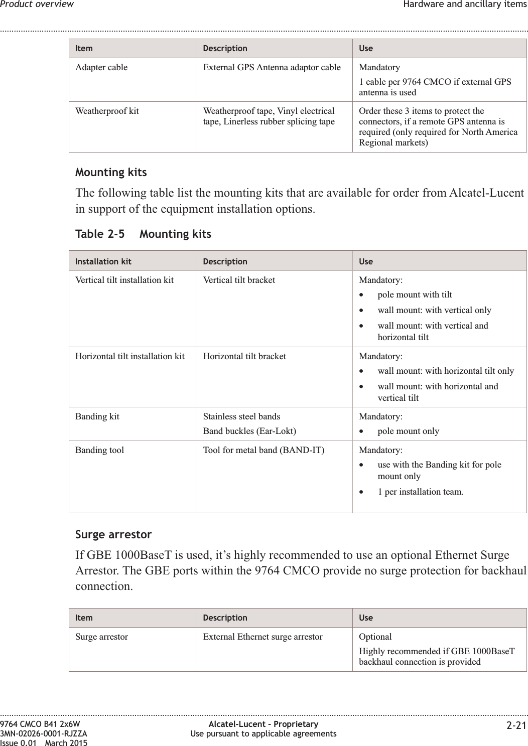
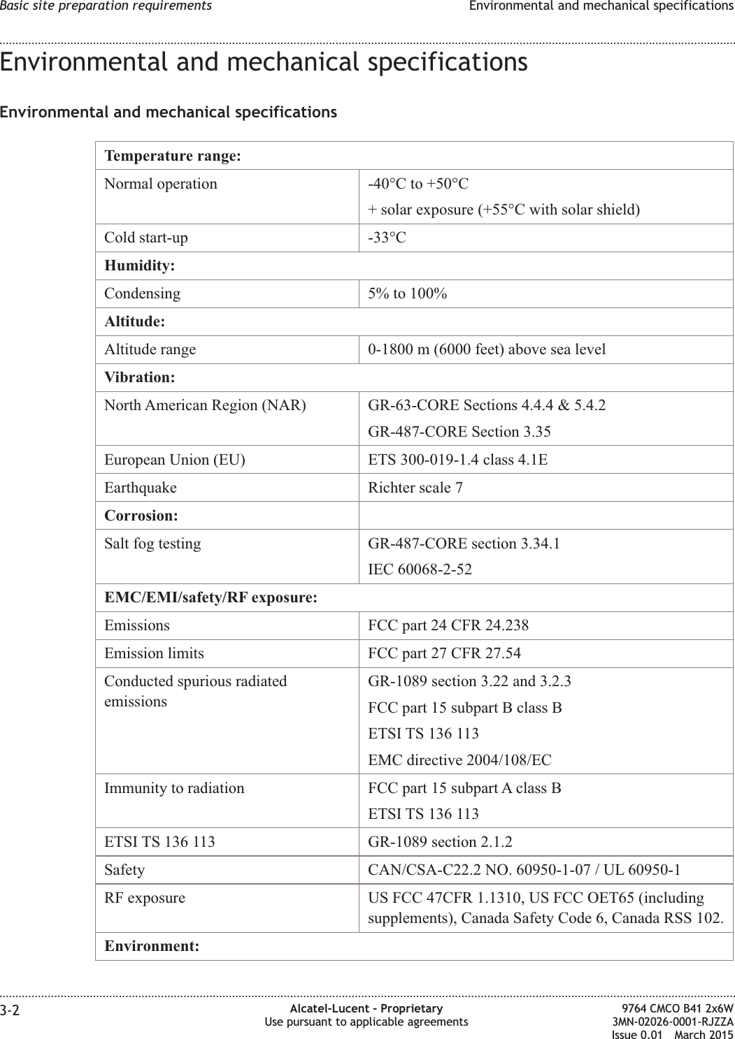
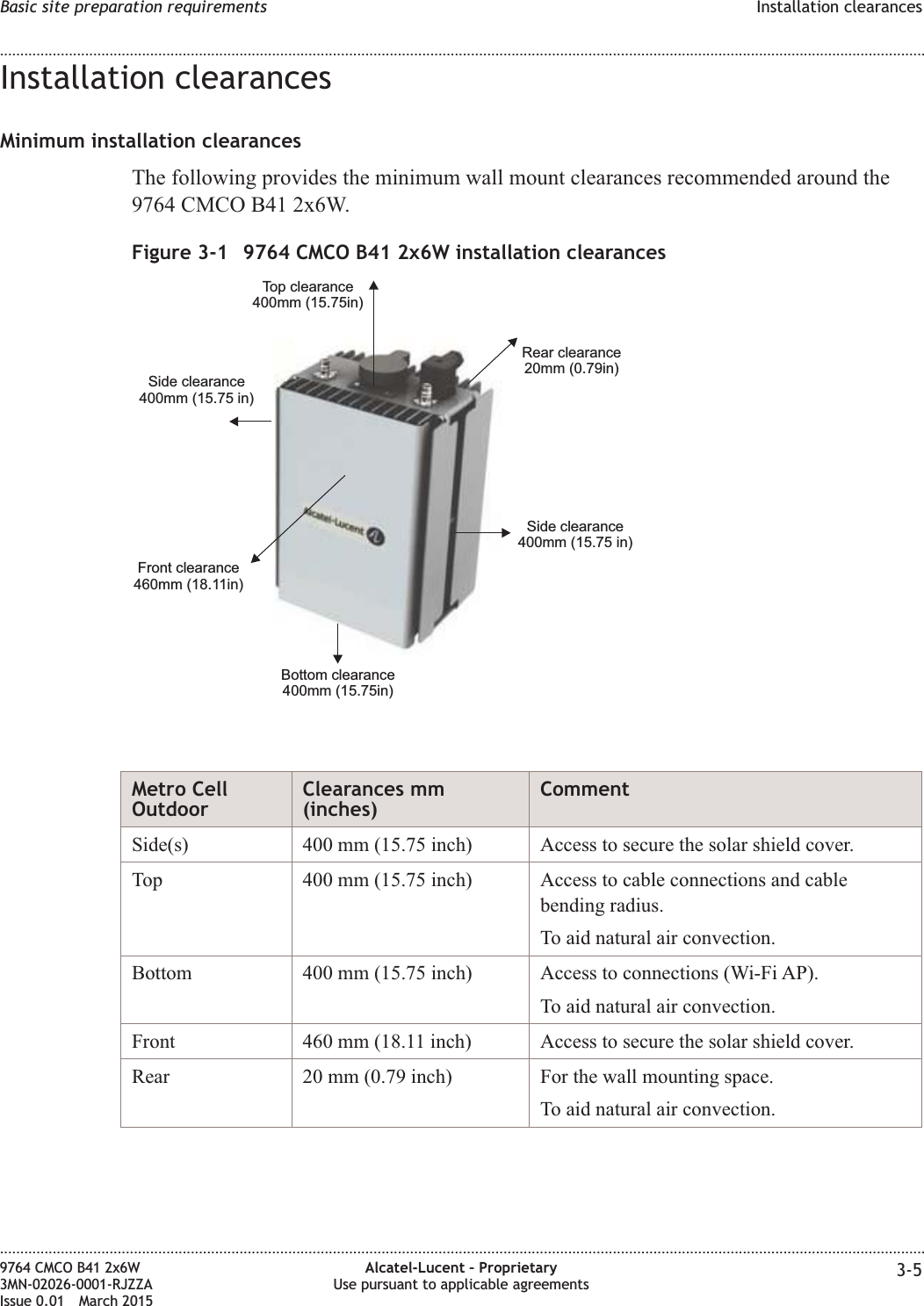
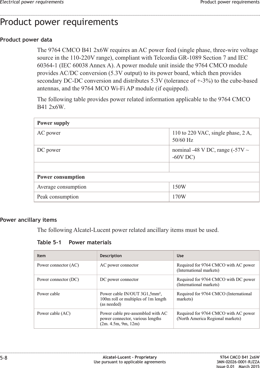
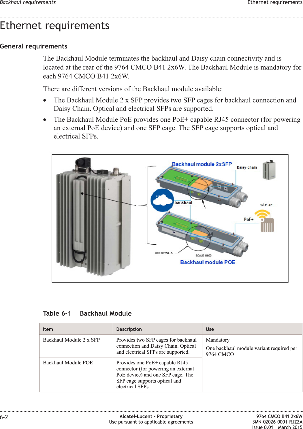
![Structure of safety statementsOverviewThis topic describes the components of safety statements that appear in this document.General structureSafety statements include the following structural elements:Item Structure element Purpose1 Safety alert symbol Indicates the potential for personal injury(optional)2 Safety symbol Indicates hazard type (optional)3 Signal word Indicates the severity of the hazard4 Hazard type Describes the source of the risk of damage orinjury5 Safety message Consequences if protective measures fail6 Avoidance message Protective measures to take to avoid the hazard7 Identifier The reference ID of the safety statement(optional)SAMPLELifting this equipment by yourself can result in injurydue to the size and weight of the equipment.Always use three people or a lifting device to transportand position this equipment. [ABC123]CAUTIONLifting hazardSafety Structure of safety statements........................................................................................................................................................................................................................................................................................................................................................................................................................................................................1-2 Alcatel-Lucent – ProprietaryUse pursuant to applicable agreements9764 CMCO B41 2x6W3MN-02026-0001-RJZZAIssue 0.01 March 2015DRAFTDRAFT](https://usermanual.wiki/Alcatel-Lucent-Deutschland/CMCOB41AC2X6.Site-Preparation-Manual/User-Guide-2663919-Page-18.png)
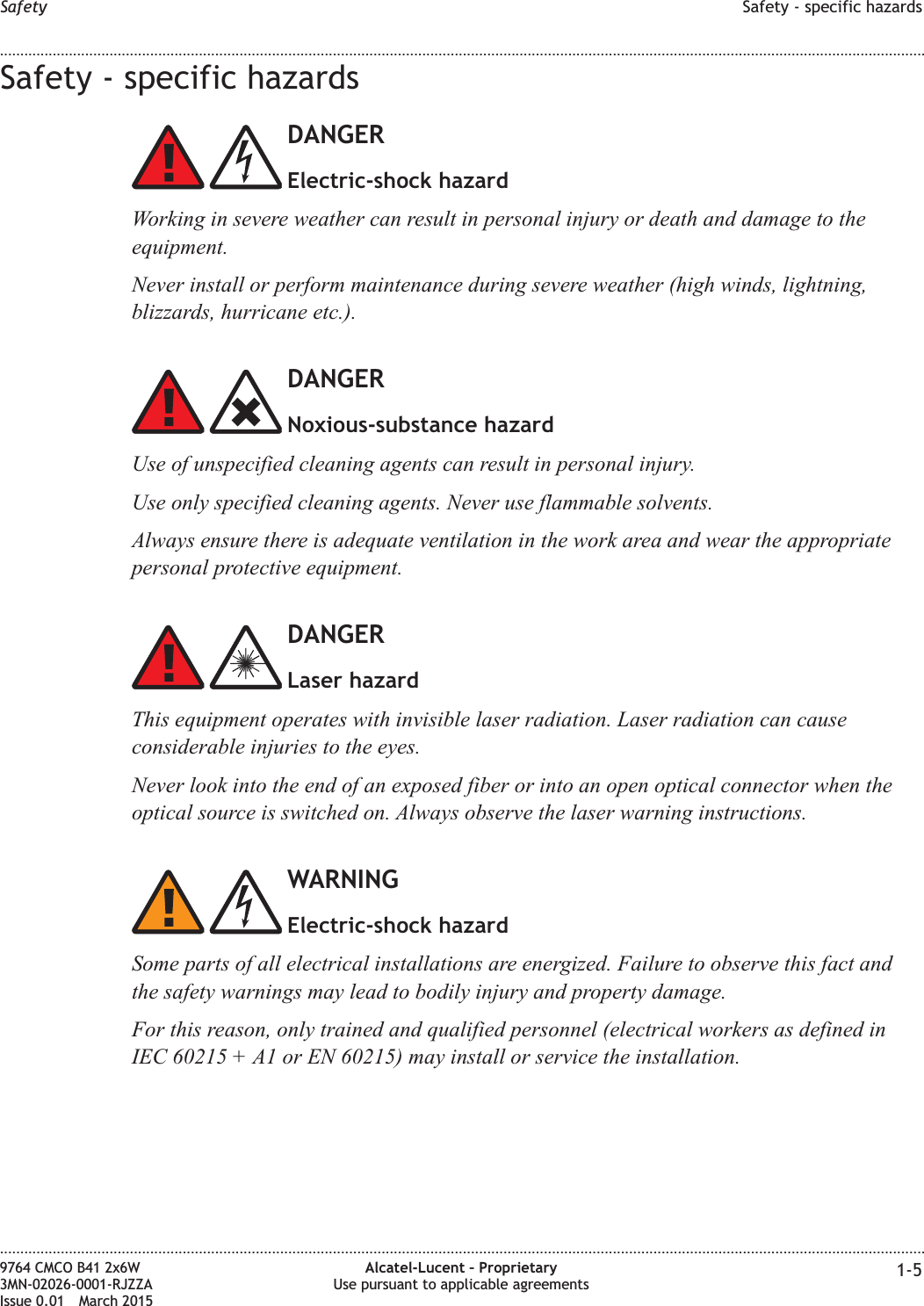
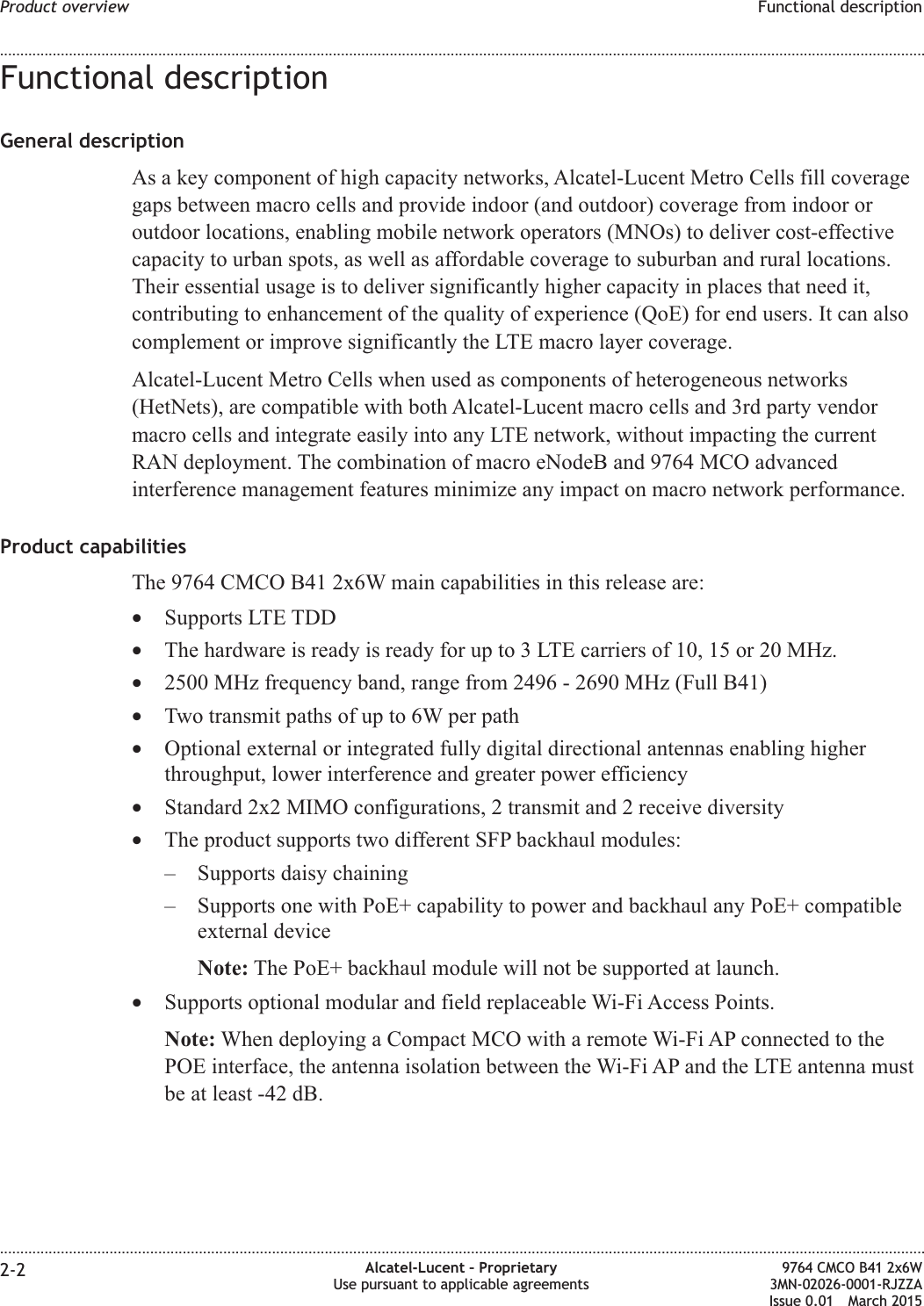
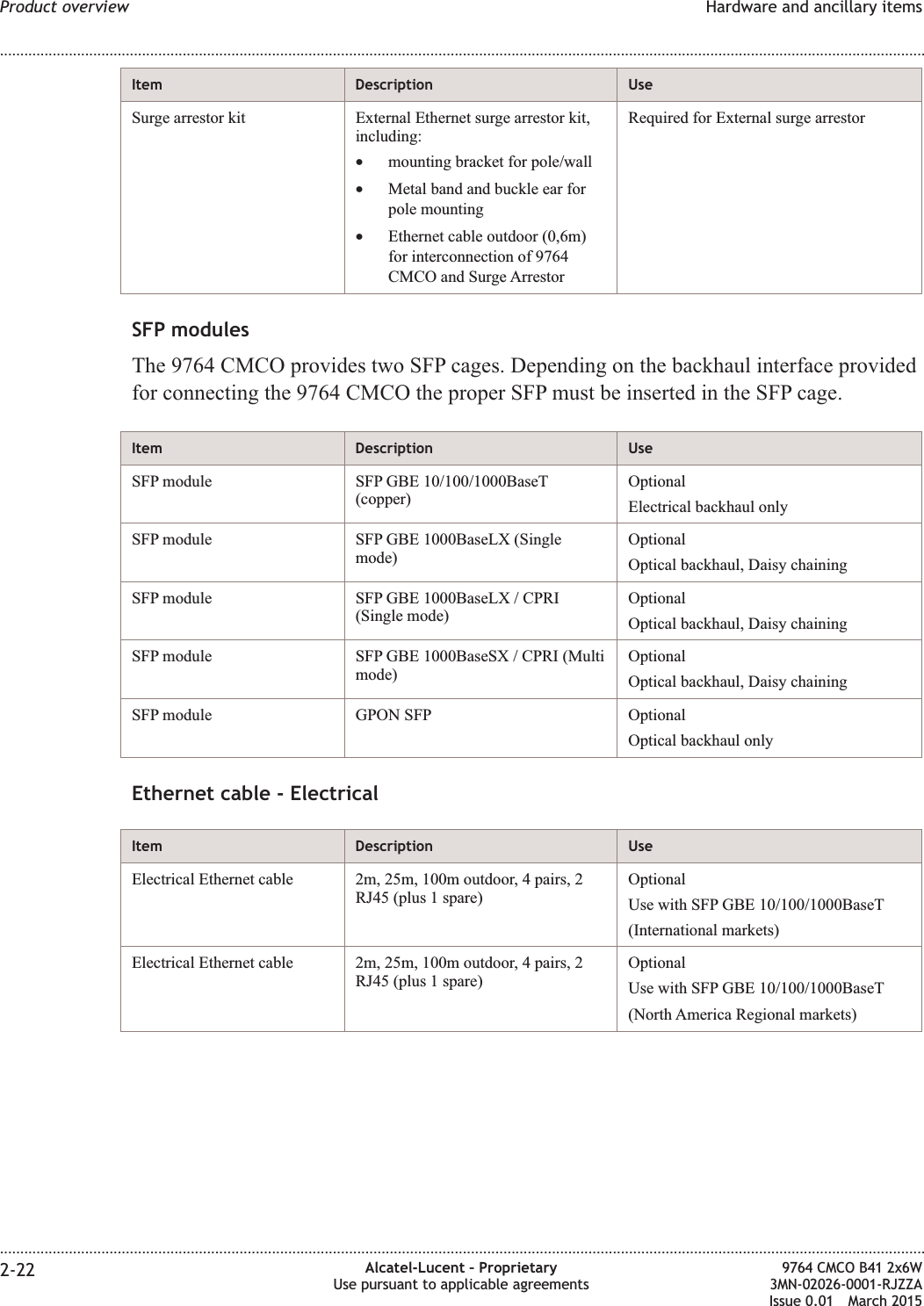
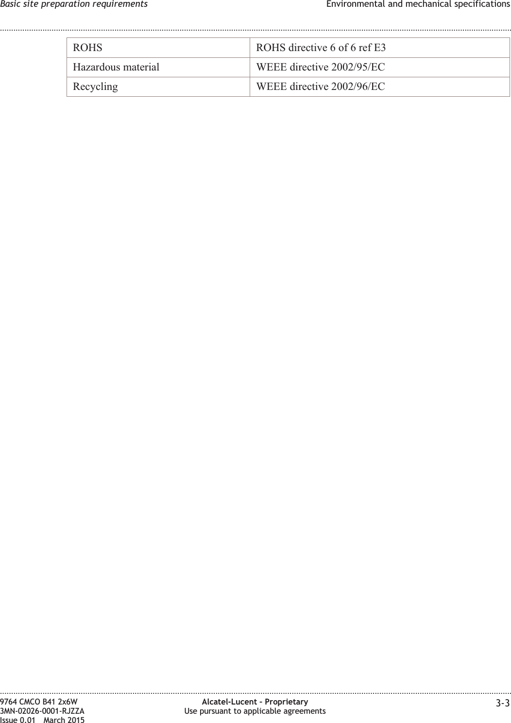
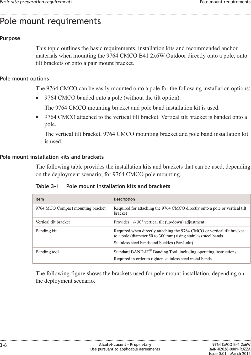

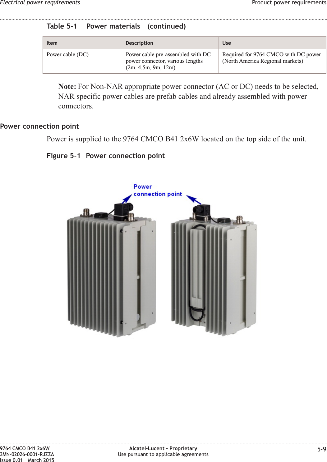

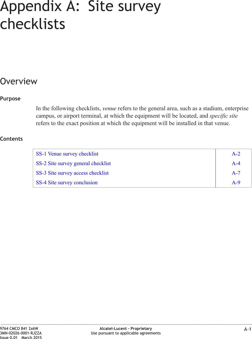

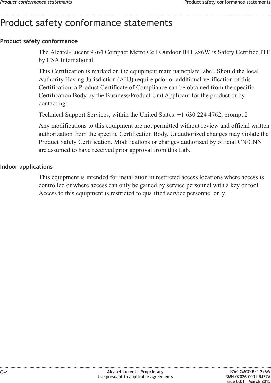
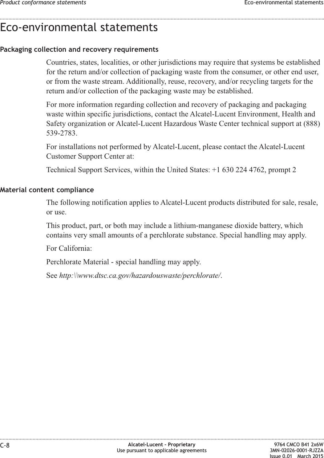
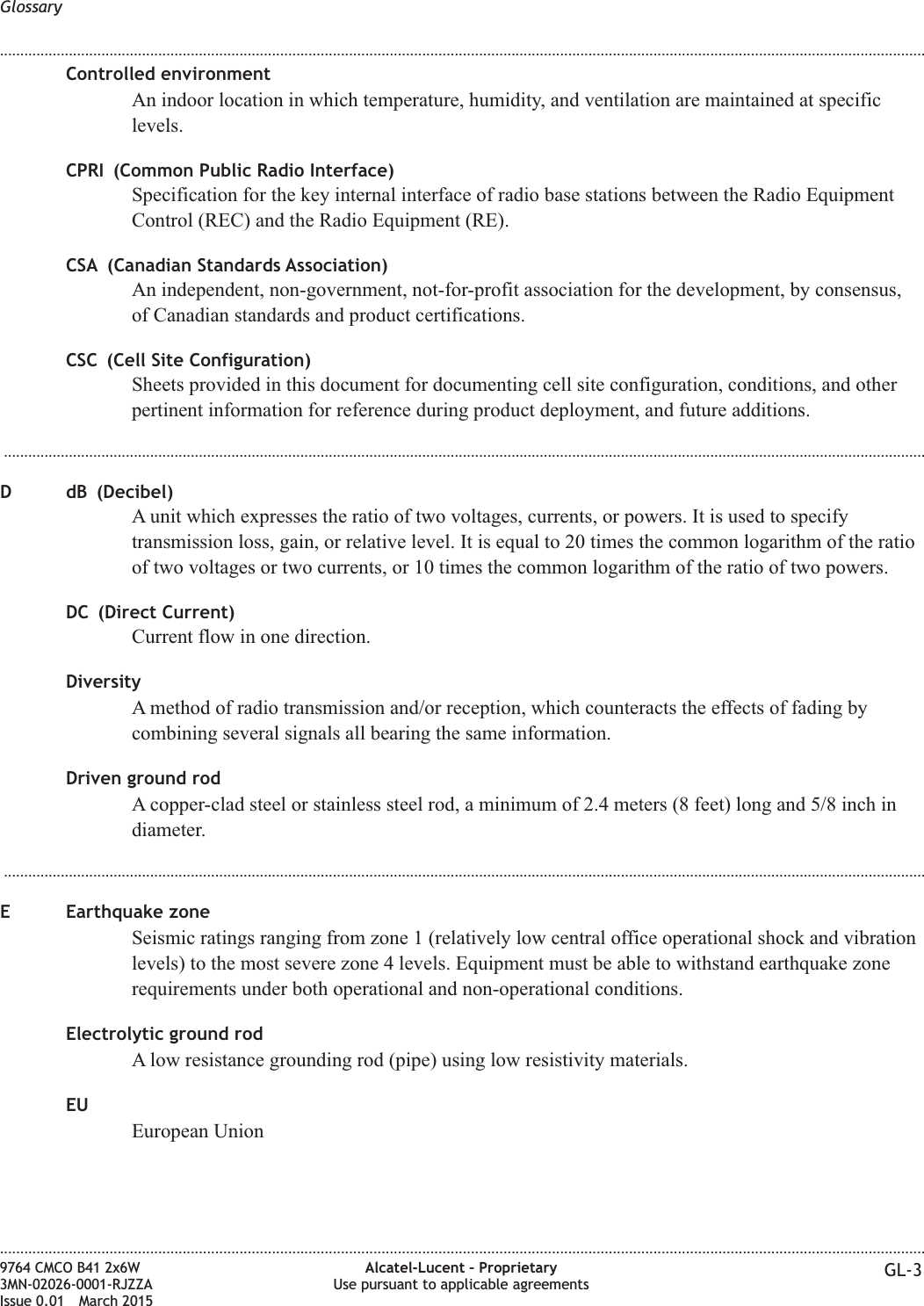
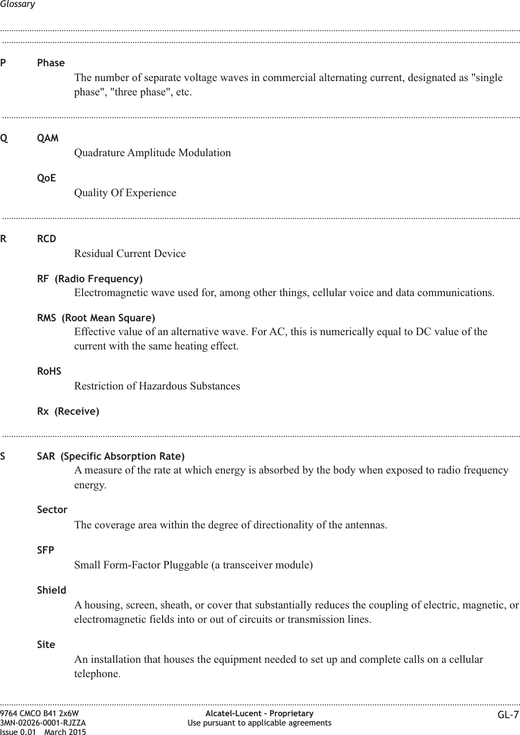
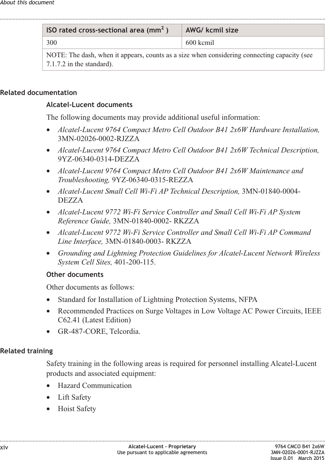
![SP-1 Site preparation general checklistPurposeWhere applicable, the following items must be completed prior to the installation of siteequipment. Circle the correct letter for the corresponding item descriptions.Item#Description Yes(Y)No(N)N/A Comments1. Are site environmental conditions withinequipment specified operating range?Y N N/A2. Has the required space been providedaround equipment [i.e., maintenanceaccess, heat dissipation, safety]?Y N N/A3. Has a Method of Procedure (MOP) beendeveloped with the installationsupervisor?Y N N/A4. Has installer site equipment parametersheet been completed and reviewed withthe installation supervisor?Y N N/A5. Has all equipment been ordered and hasdelivery to site been scheduled?Y N N/A6. Have all necessary arrangements beenmade for access to the site?Y N N/A7. Have all necessary arrangements beenmade to get equipment onto the site(crane, etc.)?Y N N/ANotes:1. Completed by: ______________________2. Date: _______Site preparation checklists SP-1 Site preparation general checklist........................................................................................................................................................................................................................................................................................................................................................................................................................................................................B-2 Alcatel-Lucent – ProprietaryUse pursuant to applicable agreements9764 CMCO B41 2x6W3MN-02026-0001-RJZZAIssue 0.01 March 2015DRAFTDRAFT](https://usermanual.wiki/Alcatel-Lucent-Deutschland/CMCOB41AC2X6.Site-Preparation-Manual/User-Guide-2663919-Page-98.png)