Alcatel Lucent Deutschland CMCOB41AC2X6 9764 Compact Metro Cell Outdoor B41 2x6W User Manual Site Preparation Manual
Alcatel-Lucent Deutschland AG 9764 Compact Metro Cell Outdoor B41 2x6W Site Preparation Manual
Contents
- 1. Hardware Installation Manual
- 2. Site Preparation Manual
Site Preparation Manual

Title page
Alcatel-Lucent 9764
Compact Metro Cell Outdoor B41 2x6W
Site Preparation
3MN-02026-0001-RJZZA
Issue 0.01 | March 2015
Alcatel-Lucent – Proprietary
Use pursuant to applicable agreements
Use pursuant to applicable agreements
D
RAFT
D
RAFT

Legal notice
Legal notice
Alcatel, Lucent, Alcatel-Lucent and the Alcatel-Lucent logo are trademarks of Alcatel-Lucent. All other trademarks are the property of their respective
owners.
The information presented is subject to change without notice. Alcatel-Lucent assumes no responsibility for inaccuracies contained herein.
Copyright © 2015 Alcatel-Lucent. All rights reserved.
Contains proprietary/trade secret information which is the property of Alcatel-Lucent and must not be made available to, or copied or used by anyone outside
Alcatel-Lucent without its written authorization.
Not to be used or disclosed except in accordance with applicable agreements.
Notice
Every effort was made to ensure that the information in this document was complete and accurate at the time of printing. However, information is subjectto
change.
Use pursuant to applicable agreements
Alcatel-Lucent – Proprietary
Use pursuant to applicable agreements
D
RAFT
D
RAFT
Contents
About this document
Purpose ............................................................................................................................................................................................. xixi
What's new ...................................................................................................................................................................................... xixi
Safety information ........................................................................................................................................................................ xixi
Intended audience ......................................................................................................................................................................... xixi
Systems supported ........................................................................................................................................................................ xixi
Conventions used ........................................................................................................................................................................ xiixii
Related documentation ............................................................................................................................................................. xivxiv
Related training ........................................................................................................................................................................... xivxiv
Site preparation checklists ........................................................................................................................................................ xvxv
Base station configuration sheets ........................................................................................................................................... xvxv
Document support ....................................................................................................................................................................... xvxv
Technical support ....................................................................................................................................................................... xvixvi
How to order ................................................................................................................................................................................ xvixvi
How to comment ........................................................................................................................................................................ xvixvi
1Safety
Overview ...................................................................................................................................................................................... 1-11-1
Structure of safety statements ............................................................................................................................................... 1-21-2
Safety ............................................................................................................................................................................................. 1-41-4
Safety - specific hazards ......................................................................................................................................................... 1-51-5
Product safety .......................................................................................................................................................................... 1-101-10
2Product overview
Overview ...................................................................................................................................................................................... 2-12-1
....................................................................................................................................................................................................................................
9764 CMCO B41 2x6W
3MN-02026-0001-RJZZA
Issue 0.01 March 2015
Alcatel-Lucent – Proprietary
Use pursuant to applicable agreements iii
D
RAFT
D
RAFT
Functional description ............................................................................................................................................................. 2-22-2
Physical description ................................................................................................................................................................. 2-42-4
MCO weights and dimensions ........................................................................................................................................... 2-152-15
Supported installation options ........................................................................................................................................... 2-162-16
Hardware and ancillary items ............................................................................................................................................ 2-182-18
3Basic site preparation requirements
Overview ...................................................................................................................................................................................... 3-13-1
Environmental and mechanical specifications ............................................................................................................... 3-23-2
Site requirements ...................................................................................................................................................................... 3-43-4
Installation clearances ............................................................................................................................................................. 3-53-5
Pole mount requirements ....................................................................................................................................................... 3-63-6
Wall mount requirements ....................................................................................................................................................... 3-83-8
4Grounding and lightning protection requirements
Overview ...................................................................................................................................................................................... 4-14-1
Grounding and lightning protection ................................................................................................................................... 4-24-2
Product grounding .................................................................................................................................................................... 4-44-4
5Electrical power requirements
Overview ...................................................................................................................................................................................... 5-15-1
Site power requirements (AC) ............................................................................................................................................. 5-25-2
Site power requirements (DC) ............................................................................................................................................. 5-55-5
Product power requirements ................................................................................................................................................. 5-85-8
6Backhaul requirements
Overview ...................................................................................................................................................................................... 6-16-1
Ethernet requirements ............................................................................................................................................................. 6-26-2
7Antenna requirements
Overview ...................................................................................................................................................................................... 7-17-1
Contents
....................................................................................................................................................................................................................................
....................................................................................................................................................................................................................................
iv Alcatel-Lucent – Proprietary
Use pursuant to applicable agreements
9764 CMCO B41 2x6W
3MN-02026-0001-RJZZA
Issue 0.01 March 2015
D
RAFT
D
RAFT
General antenna cable requirements .................................................................................................................................. 7-27-2
Antenna configuration options ............................................................................................................................................. 7-37-3
ASite survey checklists
Overview ..................................................................................................................................................................................... A-1A-1
SS-1 Venue survey checklist ................................................................................................................................................ A-2A-2
SS-2 Site survey general checklist .................................................................................................................................... A-4A-4
SS-3 Site survey access checklist ...................................................................................................................................... A-7A-7
SS-4 Site survey conclusion ................................................................................................................................................ A-9A-9
BSite preparation checklists
Overview ..................................................................................................................................................................................... B-1B-1
SP-1 Site preparation general checklist ........................................................................................................................... B-2B-2
SP-2 Site preparation power source checklist ............................................................................................................... B-3B-3
SP-3 Site preparation grounding checklist ...................................................................................................................... B-4B-4
SP-4 Site preparation RF antenna checklist ................................................................................................................... B-6B-6
SP-5 Site preparation GPS antenna checklist ................................................................................................................ B-7B-7
Site preparation punch list sheet ......................................................................................................................................... B-9B-9
Site preparation punchlist sheet ........................................................................................................................................ B-10B-10
CProduct conformance statements
Overview ..................................................................................................................................................................................... C-1C-1
Federal Communications Commission ............................................................................................................................ C-2C-2
Product safety conformance statements ........................................................................................................................... C-4C-4
Antenna exposure statements .............................................................................................................................................. C-5C-5
FDA/IEC optical transmitter product compliance statements ................................................................................. C-7C-7
Eco-environmental statements ............................................................................................................................................ C-8C-8
Glossary
Index
Contents
....................................................................................................................................................................................................................................
....................................................................................................................................................................................................................................
9764 CMCO B41 2x6W
3MN-02026-0001-RJZZA
Issue 0.01 March 2015
Alcatel-Lucent – Proprietary
Use pursuant to applicable agreements v
D
RAFT
D
RAFT
Contents
....................................................................................................................................................................................................................................
....................................................................................................................................................................................................................................
vi Alcatel-Lucent – Proprietary
Use pursuant to applicable agreements
9764 CMCO B41 2x6W
3MN-02026-0001-RJZZA
Issue 0.01 March 2015
D
RAFT
D
RAFT
List of tables
1Terminology .................................................................................................................................................................. xiixii
2-1 9764 Compact Metro Cell Outdoor B41 2x6W ........................................................................................... 2-182-18
2-2 Backhaul Module .................................................................................................................................................... 2-182-18
2-3 Basic installation Kit Compact ........................................................................................................................... 2-182-18
2-4 Mounting frame ....................................................................................................................................................... 2-192-19
2-5 Mounting kits ............................................................................................................................................................ 2-212-21
3-1 Pole mount installation kits and brackets ......................................................................................................... 3-63-6
3-2 Wall mount installation brackets .......................................................................................................................... 3-83-8
4-1 Grounding materials ................................................................................................................................................. 4-44-4
5-1 Power materials .......................................................................................................................................................... 5-85-8
6-1 Backhaul Module ....................................................................................................................................................... 6-26-2
6-2 Ethernet cable - Electrical ...................................................................................................................................... 6-36-3
6-3 Ethernet cable - Optical ........................................................................................................................................... 6-36-3
6-4 Ethernet cable - Optical for GPON ..................................................................................................................... 6-46-4
7-1 Main Characteristics of Antenna Array ............................................................................................................. 7-37-3
....................................................................................................................................................................................................................................
9764 CMCO B41 2x6W
3MN-02026-0001-RJZZA
Issue 0.01 March 2015
Alcatel-Lucent – Proprietary
Use pursuant to applicable agreements vii
D
RAFT
D
RAFT
List of tables
....................................................................................................................................................................................................................................
....................................................................................................................................................................................................................................
viii Alcatel-Lucent – Proprietary
Use pursuant to applicable agreements
9764 CMCO B41 2x6W
3MN-02026-0001-RJZZA
Issue 0.01 March 2015
D
RAFT
D
RAFT
List of figures
2-1 Front view .................................................................................................................................................................... 2-52-5
2-2 Front view of a 9764 CMCO B41 2x6W with solar shield and attached antennas ........................... 2-62-6
2-3 Front view of a 9764 CMCO B41 2x6W with a 9764 MCO Wi-Fi AP attached ............................... 2-62-6
2-4 Rear view ...................................................................................................................................................................... 2-72-7
2-5 Top view ....................................................................................................................................................................... 2-82-8
2-6 9764 CMCO B41 2x6W connection interfaces ........................................................................................... 2-102-10
2-7 Solar shield with attached antenna array ........................................................................................................ 2-112-11
2-8 9764 CMCO B41 2x6W with external GPS/Glonass antenna ............................................................... 2-122-12
2-9 LED position and orientation .............................................................................................................................. 2-132-13
2-10 Installation examples ............................................................................................................................................. 2-162-16
2-11 9764 MCO Wi-Fi AP module attached to 9764 CMCO (front view) .................................................. 2-172-17
3-1 9764 CMCO B41 2x6W installation clearances ............................................................................................ 3-53-5
3-2 Pole mount banding and brackets ........................................................................................................................ 3-73-7
3-3 9764 CMCO wall mount examples ..................................................................................................................... 3-93-9
5-1 Power connection point ........................................................................................................................................... 5-95-9
6-1 Ethernet surge arrestor ............................................................................................................................................. 6-46-4
7-1 9764 CMCO with antenna ...................................................................................................................................... 7-37-3
7-2 Default GPS antenna configuration .................................................................................................................... 7-47-4
7-3 Remote GPS antenna configuration .................................................................................................................... 7-57-5
....................................................................................................................................................................................................................................
9764 CMCO B41 2x6W
3MN-02026-0001-RJZZA
Issue 0.01 March 2015
Alcatel-Lucent – Proprietary
Use pursuant to applicable agreements ix
D
RAFT
D
RAFT
List of figures
....................................................................................................................................................................................................................................
....................................................................................................................................................................................................................................
xAlcatel-Lucent – Proprietary
Use pursuant to applicable agreements
9764 CMCO B41 2x6W
3MN-02026-0001-RJZZA
Issue 0.01 March 2015
D
RAFT
D
RAFT

About this documentAbout this document
Purpose
This document covers the basic site preparation guidelines that should be used to plan an
Alcatel-Lucent 9764 Compact Metro Cell Outdoor B41 2x6W. Specific tasks are outlined
that should be completed at the job site before an installation can begin.
What's new
The major changes introduced in this issue of the document are described in the following
paragraphs.
Feature/
enhancement
Description Location
Alcatel-Lucent
9764 Compact
Metro Cell Outdoor
B41 2x6W
Created the first draft for Alcatel-Lucent
9764 Compact Metro Cell Outdoor B41
2x6W.
entire document
Safety information
For your safety, this document contains safety statements. Safety statements are given at
points where risks of damage to personnel, equipment, and operation may exist. Failure to
follow the directions in a safety statement may result in serious consequences.
Intended audience
The audience for this document is Site Preparation personnel relating to the
Alcatel-Lucent 9764 Compact Metro Cell Outdoor B41 2x6W product.
Systems supported
This document applies to the following 9764 CMCO products:
•Alcatel-Lucent 9764 Compact Metro Cell Outdoor B41 2x6W
•Alcatel-Lucent 9764 Metro Cell OutdoorWi-Fi AP (optional equipment)
...................................................................................................................................................................................................................................
9764 CMCO B41 2x6W
3MN-02026-0001-RJZZA
Issue 0.01 March 2015
Alcatel-Lucent – Proprietary
Use pursuant to applicable agreements xi
D
RAFT
D
RAFT

Refer to Alcatel-Lucent Small Cell Wi-Fi AP Technical Description,
3MN-01840-0004-DEZZA for Wi-Fi AP product details.
Conventions used
The following conventions are used in this document:
Vocabulary conventions
The following vocabulary conventions are also used when referring to Alcatel-Lucent
products:
Table 1 Terminology
Term Description/Meaning
9764 MCO Wi-Fi AP Refers to the optional Alcatel-Lucent 9764 Metro Cell Outdoor
Wi-Fi Access Point (AP) module, supporting Wi-Fi network access.
9764 CMCO module Refers to the module that contains the complete base station,
including baseband unit, radio unit and antenna.
9764 CMCO B41 2x6W Refers to the Alcatel-Lucent 9764 Compact Metro Cell Outdoor
V2.2 B41 LTE 2x6W model of the 9764 CMCO.
9764 CMCO The 9764 CMCO consists of the following modules: the 9764
CMCO, and optionally the 9764 MCO Wi-Fi AP.
Naming conventions
In this information product, the Alcatel-Lucent 9764 Compact Metro Cell Outdoor B41
2x6W at times will be referred to 9764 CMCO.
Typographical conventions
The typographical conventions used in this document are described in the following table.
Appearance Description
emphasis Text that is emphasized
document titles Titles of books or other documents
graphical user interface text Text that is displayed in a graphical user
interface
variables
A value or command-line parameter that the
user provides
About this document
....................................................................................................................................................................................................................................
....................................................................................................................................................................................................................................
xii Alcatel-Lucent – Proprietary
Use pursuant to applicable agreements
9764 CMCO B41 2x6W
3MN-02026-0001-RJZZA
Issue 0.01 March 2015
D
RAFT
D
RAFT

Illustrations
The illustrations shown in this document are schematics. They do not contain all details
and exceptions, but are rather intended to highlight main points. Dimensions are shown in
millimeters with inches in parenthesis. As an example, 680.0 (26.77) equals 680
millimeters or 26.77 inches. Tolerances shall be held to 1.52 (.06) and are not cumulative.
Standard cross-sections and wire diameter of round copper conductors
The following table is from CEI/IEC 60947-1:2004, Table 1, Standard cross-sections of
round copper conductors and approximate relationship between mm2and AWG/ kcmil
sizes for reference. Additional wire sizes are included in this information product as
appropriate for the topic.
ISO rated cross-sectional area (mm2) AWG/ kcmil size
0.2 24
0.34 22
0.5 20
0.75 18
1-
1.5 16
2.5 14
412
610
10 8
16 6
25 4
35 2
-1
50 0 (1/0)
70 00 (2/0)
95 000 (3/0)
- 0000 (4/0)
120 250 kcmil
150 300 kcmil
185 350 kcmil
- 400 kcmil
240 500 kcmil
About this document
....................................................................................................................................................................................................................................
....................................................................................................................................................................................................................................
9764 CMCO B41 2x6W
3MN-02026-0001-RJZZA
Issue 0.01 March 2015
Alcatel-Lucent – Proprietary
Use pursuant to applicable agreements xiii
D
RAFT
D
RAFT

ISO rated cross-sectional area (mm2) AWG/ kcmil size
300 600 kcmil
NOTE: The dash, when it appears, counts as a size when considering connecting capacity (see
7.1.7.2 in the standard).
Related documentation
Alcatel-Lucent documents
The following documents may provide additional useful information:
•Alcatel-Lucent 9764 Compact Metro Cell Outdoor B41 2x6W Hardware Installation,
3MN-02026-0002-RJZZA
•Alcatel-Lucent 9764 Compact Metro Cell Outdoor B41 2x6W Technical Description,
9YZ-06340-0314-DEZZA
•Alcatel-Lucent 9764 Compact Metro Cell Outdoor B41 2x6W Maintenance and
Troubleshooting, 9YZ-06340-0315-REZZA
•Alcatel-Lucent Small Cell Wi-Fi AP Technical Description, 3MN-01840-0004-
DEZZA
•Alcatel-Lucent 9772 Wi-Fi Service Controller and Small Cell Wi-Fi AP System
Reference Guide, 3MN-01840-0002- RKZZA
•Alcatel-Lucent 9772 Wi-Fi Service Controller and Small Cell Wi-Fi AP Command
Line Interface, 3MN-01840-0003- RKZZA
•Grounding and Lightning Protection Guidelines for Alcatel-Lucent Network Wireless
System Cell Sites, 401-200-115.
Other documents
Other documents as follows:
•Standard for Installation of Lightning Protection Systems, NFPA
•Recommended Practices on Surge Voltages in Low Voltage AC Power Circuits, IEEE
C62.41 (Latest Edition)
•GR-487-CORE, Telcordia.
Related training
Safety training in the following areas is required for personnel installing Alcatel-Lucent
products and associated equipment:
•Hazard Communication
•Lift Safety
•Hoist Safety
About this document
....................................................................................................................................................................................................................................
....................................................................................................................................................................................................................................
xiv Alcatel-Lucent – Proprietary
Use pursuant to applicable agreements
9764 CMCO B41 2x6W
3MN-02026-0001-RJZZA
Issue 0.01 March 2015
D
RAFT
D
RAFT
•Lock Out/Tag Out
•Accident/Incident Reporting.
Other related training is for:
•Integration into the cell site
•Operation, Administration, and Maintenance (OA&M).
Site preparation checklists
All site preparation activities, as well as adherence to the guidelines, should be verified
prior to the installation of the cell site equipment.
Various checklists and punchlist sheets have been provided in Appendix A of this
document to aid customers and Alcatel-Lucent personnel during a base station site
Method of Procedure (MOP) walk-through prior to the equipment installation.
Utilization of the checklists helps ensure a quality installation and provides a base station
site history file for later reference. The punchlist sheets are used to track completion of
any outstanding site preparation items, and to aid in the project management of
installation resources.
Base station configuration sheets
Configuration sheets are provided in Appendix B of this document to aid the Customer,
Equipment Engineering, and Wireless Project Management during the various stages of
product deployment. The configuration sheets are used to document the base station
equipment configuration, conditions, and other pertinent information for reference during
product deployment, and future additions. The configuration sheets should be completed
during the equipment engineering phase. Reference to this information during MOP
walk-through assists with completion of the site preparation checklists.
Document support
For support in using this or any other Alcatel-Lucent document, contact Alcatel-Lucent at
the following telephone numbers.
From United States
•If you are using a landline, a cellular phone or VoIP, dial this number: 1-888-582-3688
From other countries
•If you are using a cellular phone or VoIP, dial this number: +1-630-224-2485
•If you are using a landline (phone without a plus [+] character), replace the plus sign
with your country's exit code. Dial this number: Exit code for the country of origin:
1-630-224-2485. See the country-specific exit codes listed here.
These numbers apply for document support only. Please see the section “Technical
support” for details about product hardware, software, and technical support.
About this document
....................................................................................................................................................................................................................................
....................................................................................................................................................................................................................................
9764 CMCO B41 2x6W
3MN-02026-0001-RJZZA
Issue 0.01 March 2015
Alcatel-Lucent – Proprietary
Use pursuant to applicable agreements xv
D
RAFT
D
RAFT
Technical support
For technical support, contact your local Alcatel-Lucent customer support team. See the
Alcatel-Lucent Support web site (http://www.alcatel-lucent.com/support/) for contact
information.
How to order
To order Alcatel-Lucent documents, contact your local sales representative or use Online
Customer Support (OLCS) (http://support.alcatel-lucent.com (http://support.alcatel-
lucent.com)) .
How to comment
Note to reviewers: The following "How to comment" text will appear in the final
document when it is published. However, the feedback method described below is for use
only on final documents. Please send your review comments to the author using the
process you were given when you received this draft document.
To comment on this document, go to the Online Comment Form (http://infodoc.alcatel-
lucent.com/comments/) or e-mail your comments to the Comments Hotline
(comments@alcatel-lucent.com).
About this document
....................................................................................................................................................................................................................................
....................................................................................................................................................................................................................................
xvi Alcatel-Lucent – Proprietary
Use pursuant to applicable agreements
9764 CMCO B41 2x6W
3MN-02026-0001-RJZZA
Issue 0.01 March 2015
D
RAFT
D
RAFT

11Safety
Overview
Purpose
This chapter covers safety precautions.
Contents
Structure of safety statements 1-2
Safety 1-4
Safety - specific hazards 1-5
Product safety 1-10
...................................................................................................................................................................................................................................
9764 CMCO B41 2x6W
3MN-02026-0001-RJZZA
Issue 0.01 March 2015
Alcatel-Lucent – Proprietary
Use pursuant to applicable agreements 1-1
D
RAFT
D
RAFT
Structure of safety statements
Overview
This topic describes the components of safety statements that appear in this document.
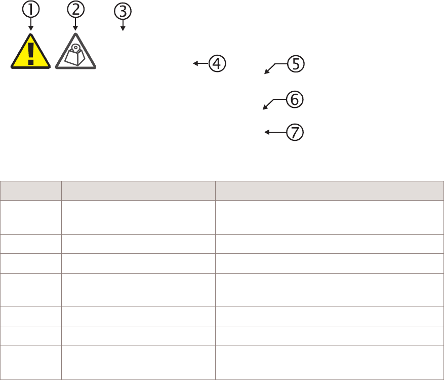
General structure
Safety statements include the following structural elements:
Item Structure element Purpose
1 Safety alert symbol Indicates the potential for personal injury
(optional)
2 Safety symbol Indicates hazard type (optional)
3 Signal word Indicates the severity of the hazard
4 Hazard type Describes the source of the risk of damage or
injury
5 Safety message Consequences if protective measures fail
6 Avoidance message Protective measures to take to avoid the hazard
7 Identifier The reference ID of the safety statement
(optional)
SAMPLE
Lifting this equipment by yourself can result in injury
due to the size and weight of the equipment.
Always use three people or a lifting device to transport
and position this equipment. [ABC123]
CAUTION
Lifting hazard
Safety Structure of safety statements
....................................................................................................................................................................................................................................
....................................................................................................................................................................................................................................
1-2 Alcatel-Lucent – Proprietary
Use pursuant to applicable agreements
9764 CMCO B41 2x6W
3MN-02026-0001-RJZZA
Issue 0.01 March 2015
D
RAFT
D
RAFT

Signal words
The signal words identify the hazard severity levels as follows:
Signal word Meaning
DANGER Indicates an extremely hazardous situation which, if not avoided, will
result in death or serious injury.
WARNING Indicates a hazardous situation which, if not avoided, could result in
death or serious injury.
CAUTION Indicates a hazardous situation which, if not avoided, could result in
minor or moderate injury.
NOTICE Indicates a hazardous situation not related to personal injury.
Safety Structure of safety statements
....................................................................................................................................................................................................................................
....................................................................................................................................................................................................................................
9764 CMCO B41 2x6W
3MN-02026-0001-RJZZA
Issue 0.01 March 2015
Alcatel-Lucent – Proprietary
Use pursuant to applicable agreements 1-3
D
RAFT
D
RAFT

Safety
General precautions for installation procedures
WARNING
Electric shock and equipment damage
Failure to observe these safety precautions may result in personal injury or damage to
equipment.
•Read and understand all instructions.
•Follow all warnings and instructions marked on this product.
•Installation and maintenance procedures must be followed and performed by trained
personnel only.
•The equipment must be provided with a readily accessible disconnect device as part of
site preparation.
•Grounding and circuit continuity is vital for safe operation of the equipment. Never
operate the equipment with grounding/bonding conductor disconnected.
•Install only equipment identified in the product's installation manual. Use of other
equipment may result in an improper connection which could lead to fire or injury.
•Use caution when installing or modifying telecommunications lines.
•The product has multiple power inputs. Before servicing, Disconnect all inputs to
reduce the risk of energy hazards.
•For continued protection against risk of fire, all fuses used in this product must be
replaced only with fuses of the same type and rating.
•Never install telecommunications wiring during a lightning storm.
•Never install telecommunications connections in wet locations.
•Never touch uninsulated wiring or terminals carrying direct current or ringing
current, and never leave this wiring exposed. Protect and tape uninsulated wiring and
terminals to avoid risk of fire, electrical shock, and injury to personnel.
•Never spill liquids of any kind on the product.
•To reduce the risk of an electrical shock, do not disassemble the product. Opening and
removing covers and/or circuit boards may expose you to dangerous voltages or other
risks. Incorrect reassembly can cause electrical shock when the unit is subsequently
used.
Safety Safety
....................................................................................................................................................................................................................................
....................................................................................................................................................................................................................................
1-4 Alcatel-Lucent – Proprietary
Use pursuant to applicable agreements
9764 CMCO B41 2x6W
3MN-02026-0001-RJZZA
Issue 0.01 March 2015
D
RAFT
D
RAFT
Safety - specific hazards
DANGER
Electric-shock hazard
Working in severe weather can result in personal injury or death and damage to the
equipment.
Never install or perform maintenance during severe weather (high winds, lightning,
blizzards, hurricane etc.).
DANGER
Noxious-substance hazard
Use of unspecified cleaning agents can result in personal injury.
Use only specified cleaning agents. Never use flammable solvents.
Always ensure there is adequate ventilation in the work area and wear the appropriate
personal protective equipment.
DANGER
Laser hazard
This equipment operates with invisible laser radiation. Laser radiation can cause
considerable injuries to the eyes.
Never look into the end of an exposed fiber or into an open optical connector when the
optical source is switched on. Always observe the laser warning instructions.
WARNING
Electric-shock hazard
Some parts of all electrical installations are energized. Failure to observe this fact and
the safety warnings may lead to bodily injury and property damage.
For this reason, only trained and qualified personnel (electrical workers as defined in
IEC 60215 + A1 or EN 60215) may install or service the installation.
Safety Safety - specific hazards
....................................................................................................................................................................................................................................
....................................................................................................................................................................................................................................
9764 CMCO B41 2x6W
3MN-02026-0001-RJZZA
Issue 0.01 March 2015
Alcatel-Lucent – Proprietary
Use pursuant to applicable agreements 1-5
D
RAFT
D
RAFT
WARNING
Electric-shock hazard
The power supply lines to the network element are energized. Contact with parts carrying
voltage can cause health problems, possibly including death, even hours after the event.
Open and lockout the load disconnect switch in the distribution box to completely
de-energize the network element.
WARNING
Electric-shock hazard
This product may be connected to an AC main power supply and may contain an internal
battery supply. Disconnecting one power source may not de-energize the system, and can
lead to serious injury.
Disconnect and lock out the AC main power supply, if present, and the internal battery
supply, if present, before servicing the equipment.
WARNING
Laser hazard
The light from laser and high-radiance LED's may cause eye damage if absorbed by the
retina.
Safety Safety - specific hazards
....................................................................................................................................................................................................................................
....................................................................................................................................................................................................................................
1-6 Alcatel-Lucent – Proprietary
Use pursuant to applicable agreements
9764 CMCO B41 2x6W
3MN-02026-0001-RJZZA
Issue 0.01 March 2015
D
RAFT
D
RAFT

NOTICE
ESD hazard
Semiconductor devices can be damaged by electrostatic discharges.
The following rules must be complied with when handling any module containing
semiconductor components:
•Wear conductive or antistatic working clothes (for example, coat made of 100%
cotton).
•Wear the grounded wrist strap.
•Wear shoes with conductive soles on a conductive floor surface or conductive work
mat.
•Leave the modules in their original packaging until ready for use.
•Make sure there is no difference in potential between yourself, the workplace, and the
packaging before removing, unpacking, or packing a module.
•Hold the module only by the grip without touching the connection pins, tracks, or
components.
•Place modules removed from the equipment on a properly grounded approved ESD
work mat.
•Test or handle the module only with grounded tools on grounded equipment.
•Handle defective modules exactly like new ones to avoid causing further damage.
NOTICE
Condensation
Sudden changes in the weather may lead to the formation of condensation on
components. Operating the unit when condensation moisture is present can destroy the
unit.
Units which show signs of condensation must be dried before installation.
CAUTION
Laceration hazard
The equipment and the components within may have sharp edges and burrs and contact
may cause cuts and lacerations.
Beware of sharp edges and burrs, especially when working on areas inside the equipment
difficult to access.
Wear appropriate personal protective equipment.
Safety Safety - specific hazards
....................................................................................................................................................................................................................................
....................................................................................................................................................................................................................................
9764 CMCO B41 2x6W
3MN-02026-0001-RJZZA
Issue 0.01 March 2015
Alcatel-Lucent – Proprietary
Use pursuant to applicable agreements 1-7
D
RAFT
D
RAFT

NOTICE
Tools
Tools left in the working area can cause short circuits during operation which can lead to
the destruction of units.
Make sure after finishing your work that no tools, testing equipment, flashlights, etc.,
have been left in or on the equipment.
NOTICE
Inadequate circulation
Inadequate circulation of cooling air can cause some units to become too warm. This can
lead to operational impairment.
Cover all installation slots for unequipped units with blanking panels.
CAUTION
Hot-surface hazard
Touching a hot heater may cause burns.
Do not touch the heaters.
Before touching the units wait until they have cooled down, wear safety gloves and
clothes.
NOTICE
Corrosive-substance hazard
Cleaning plastic containers and lids with abrasive and aggressive cleaning agents may
cause permanent damage.
Do not use solvents, paraffin, abrasive or aggressive cleaning fluids, abrasive or
aggressive antiseptic agents or abrasive or aggressive materials.
NOTICE
Service-disruption hazard
Cleaning with water or a high-pressure cleaner will damage the components in the
equipment.
The washing down of the equipment with water or a high-pressure cleaner is not
permitted.
Safety Safety - specific hazards
....................................................................................................................................................................................................................................
....................................................................................................................................................................................................................................
1-8 Alcatel-Lucent – Proprietary
Use pursuant to applicable agreements
9764 CMCO B41 2x6W
3MN-02026-0001-RJZZA
Issue 0.01 March 2015
D
RAFT
D
RAFT

CAUTION
Lifting hazard
Lifting this equipment by yourself can result in injury due to the size and weight of the
equipment.
Always use at least three people or a lifting device to move or position this equipment.
Safety Safety - specific hazards
....................................................................................................................................................................................................................................
....................................................................................................................................................................................................................................
9764 CMCO B41 2x6W
3MN-02026-0001-RJZZA
Issue 0.01 March 2015
Alcatel-Lucent – Proprietary
Use pursuant to applicable agreements 1-9
D
RAFT
D
RAFT
Product safety
Equipment safety
Safety information for this equipment can be found on various Caution, Warning, Danger,
information labels or instructions affixed to or included with the product, its internal
assemblies or included within this document. Informational and cautionary labels may
appear near the item they address or may be grouped in a single location on the
equipment. Warnings are typically adjacent to the hazard that is noted on the label. The
instructions, cautions and warnings found on these labels must be understood and
observed by all personnel involved with the equipment installation and maintenance.
Safety Product safety
....................................................................................................................................................................................................................................
....................................................................................................................................................................................................................................
1-10 Alcatel-Lucent – Proprietary
Use pursuant to applicable agreements
9764 CMCO B41 2x6W
3MN-02026-0001-RJZZA
Issue 0.01 March 2015
D
RAFT
D
RAFT

22Product overview
Overview
Purpose
This chapter provides an overview of the Alcatel-Lucent 9764 Compact Metro Cell
Outdoor B41 2x6W.
Contents
Functional description 2-2
Physical description 2-4
MCO weights and dimensions 2-15
Supported installation options 2-16
Hardware and ancillary items 2-18
...................................................................................................................................................................................................................................
9764 CMCO B41 2x6W
3MN-02026-0001-RJZZA
Issue 0.01 March 2015
Alcatel-Lucent – Proprietary
Use pursuant to applicable agreements 2-1
D
RAFT
D
RAFT
Functional description
General description
As a key component of high capacity networks, Alcatel-Lucent Metro Cells fill coverage
gaps between macro cells and provide indoor (and outdoor) coverage from indoor or
outdoor locations, enabling mobile network operators (MNOs) to deliver cost-effective
capacity to urban spots, as well as affordable coverage to suburban and rural locations.
Their essential usage is to deliver significantly higher capacity in places that need it,
contributing to enhancement of the quality of experience (QoE) for end users. It can also
complement or improve significantly the LTE macro layer coverage.
Alcatel-Lucent Metro Cells when used as components of heterogeneous networks
(HetNets), are compatible with both Alcatel-Lucent macro cells and 3rd party vendor
macro cells and integrate easily into any LTE network, without impacting the current
RAN deployment. The combination of macro eNodeB and 9764 MCO advanced
interference management features minimize any impact on macro network performance.
Product capabilities
The 9764 CMCO B41 2x6W main capabilities in this release are:
•Supports LTE TDD
•The hardware is ready is ready for up to 3 LTE carriers of 10, 15 or 20 MHz.
•2500 MHz frequency band, range from 2496 - 2690 MHz (Full B41)
•Two transmit paths of up to 6W per path
•Optional external or integrated fully digital directional antennas enabling higher
throughput, lower interference and greater power efficiency
•Standard 2x2 MIMO configurations, 2 transmit and 2 receive diversity
•The product supports two different SFP backhaul modules:
– Supports daisy chaining
– Supports one with PoE+ capability to power and backhaul any PoE+ compatible
external device
Note: The PoE+ backhaul module will not be supported at launch.
•Supports optional modular and field replaceable Wi-Fi Access Points.
Note: When deploying a Compact MCO with a remote Wi-Fi AP connected to the
POE interface, the antenna isolation between the Wi-Fi AP and the LTE antenna must
be at least -42 dB.
Product overview Functional description
....................................................................................................................................................................................................................................
....................................................................................................................................................................................................................................
2-2 Alcatel-Lucent – Proprietary
Use pursuant to applicable agreements
9764 CMCO B41 2x6W
3MN-02026-0001-RJZZA
Issue 0.01 March 2015
D
RAFT
D
RAFT
Deployment scenario
The 9764 CMCO B41 2x6W can be deployed indoors or outdoors in public places and
can be mounted on walls, lamp posts, poles, or even on the side of a building in a vertical
orientation thanks to the Metro Compact Mounting Frame.
It can also be integrated in urban furniture such as bus shelter and information panels.
Optional tilt mounting brackets allow for the 9764 CMCO B41 2x6W to be adjusted in
vertical and/or horizontal directions at same time
Product overview Functional description
....................................................................................................................................................................................................................................
....................................................................................................................................................................................................................................
9764 CMCO B41 2x6W
3MN-02026-0001-RJZZA
Issue 0.01 March 2015
Alcatel-Lucent – Proprietary
Use pursuant to applicable agreements 2-3
D
RAFT
D
RAFT
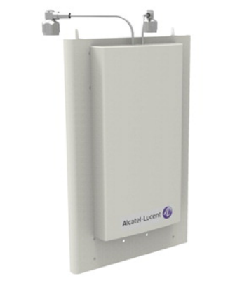
Physical description
Product overview
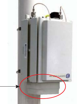
The Alcatel-Lucent 9764 Compact Metro Cell Outdoor B41 2x6W is housed in an
Alcatel-Lucent generic metallic case. The product is designed to be deployed close to the
users, usually in streets on light poles or on walls of buildings, with a vertical profile that
hides cable connectors and mounting kit for a smooth integration into the surrounding
environment.
Product overview Physical description
....................................................................................................................................................................................................................................
....................................................................................................................................................................................................................................
2-4 Alcatel-Lucent – Proprietary
Use pursuant to applicable agreements
9764 CMCO B41 2x6W
3MN-02026-0001-RJZZA
Issue 0.01 March 2015
D
RAFT
D
RAFT
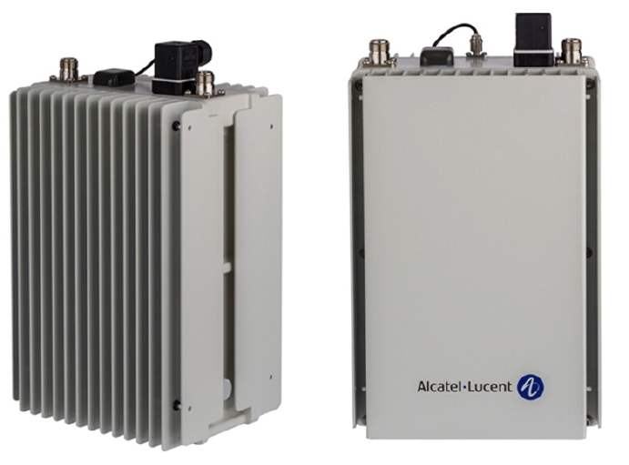
Front view of the 9764 CMCO B41 2x6W
The following figure shows the front view of the 9764 CMCO B41 2x6W with/without
solar shield.
Figure 2-1 Front view
Product overview Physical description
....................................................................................................................................................................................................................................
....................................................................................................................................................................................................................................
9764 CMCO B41 2x6W
3MN-02026-0001-RJZZA
Issue 0.01 March 2015
Alcatel-Lucent – Proprietary
Use pursuant to applicable agreements 2-5
D
RAFT
D
RAFT
The following figure shows the front view of the 9764 CMCO B41 2x6W with solar
shield and attached antennas.
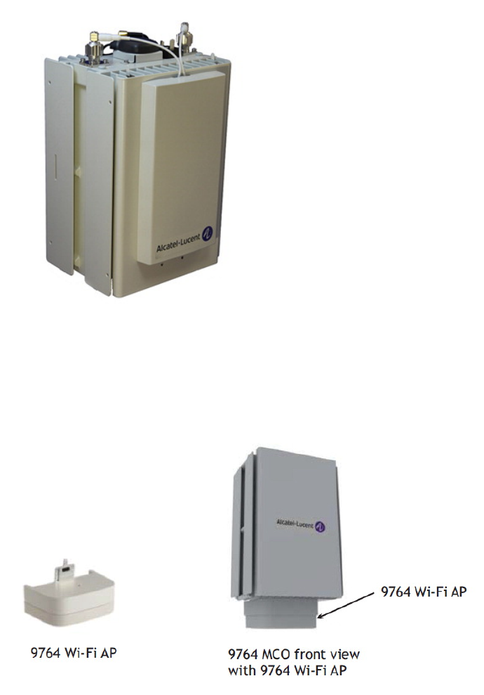
The following figure shows the 9764 CMCO B41 2x6W with 9764 Wi-Fi AP attached.
Figure 2-2 Front view of a 9764 CMCO B41 2x6W with solar shield and attached
antennas
Figure 2-3 Front view of a 9764 CMCO B41 2x6W with a 9764 MCO Wi-Fi AP
attached
Product overview Physical description
....................................................................................................................................................................................................................................
....................................................................................................................................................................................................................................
2-6 Alcatel-Lucent – Proprietary
Use pursuant to applicable agreements
9764 CMCO B41 2x6W
3MN-02026-0001-RJZZA
Issue 0.01 March 2015
D
RAFT
D
RAFT
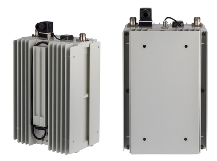
Rear view of the 9764 CMCO B41 2x6W
The following figure shows the rear view of the 9764 CMCO B41 2x6W with/without
wall mount plate.
Figure 2-4 Rear view
Product overview Physical description
....................................................................................................................................................................................................................................
....................................................................................................................................................................................................................................
9764 CMCO B41 2x6W
3MN-02026-0001-RJZZA
Issue 0.01 March 2015
Alcatel-Lucent – Proprietary
Use pursuant to applicable agreements 2-7
D
RAFT
D
RAFT
Top view of the 9764 CMCO B41 2x6W
The following figure shows the top view of the 9764 CMCO B41 2x6W.
Figure 2-5 Top view
Product overview Physical description
....................................................................................................................................................................................................................................
....................................................................................................................................................................................................................................
2-8 Alcatel-Lucent – Proprietary
Use pursuant to applicable agreements
9764 CMCO B41 2x6W
3MN-02026-0001-RJZZA
Issue 0.01 March 2015
D
RAFT
D
RAFT

9764 CMCO B41 2x6W functions
In order to simplify configurations the backhaul access function and the radio part
functions are separated, with a common interface as defined:
Unit Function Description
9764 CMCO
B41 2x6W
Radio part function Radio functions
Digital processing functions
Power supply functions
Backhaul
module
Backhaul access function
Provides power to a remote Powered
Device (PD) for PoE+ case.
Two backhaul module variants:
•Dual SFP
•SFP/PoE+
9764 MCO
Wi-Fi AP
module
Wi-Fi function Wi-Fi network access function
Refer to Alcatel-Lucent Small Cell
Wi-Fi AP Technical Description,
3MN-01840-0004-DEZZA for
Wi-Fi AP product details.
Product overview Physical description
....................................................................................................................................................................................................................................
....................................................................................................................................................................................................................................
9764 CMCO B41 2x6W
3MN-02026-0001-RJZZA
Issue 0.01 March 2015
Alcatel-Lucent – Proprietary
Use pursuant to applicable agreements 2-9
D
RAFT
D
RAFT
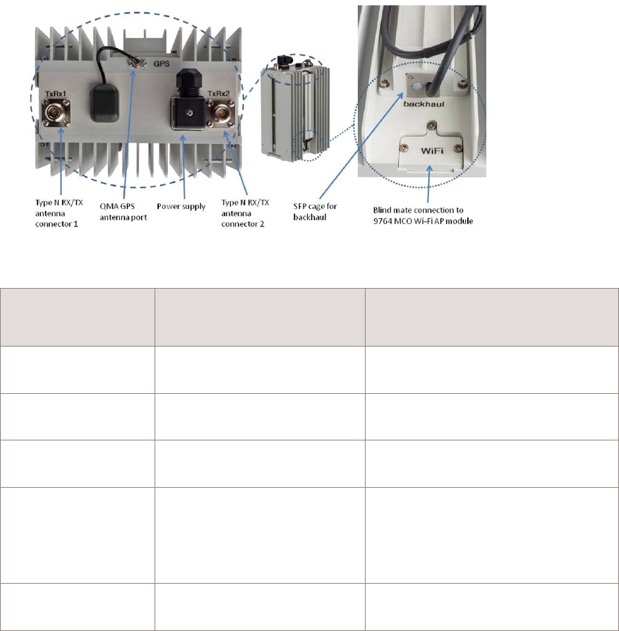
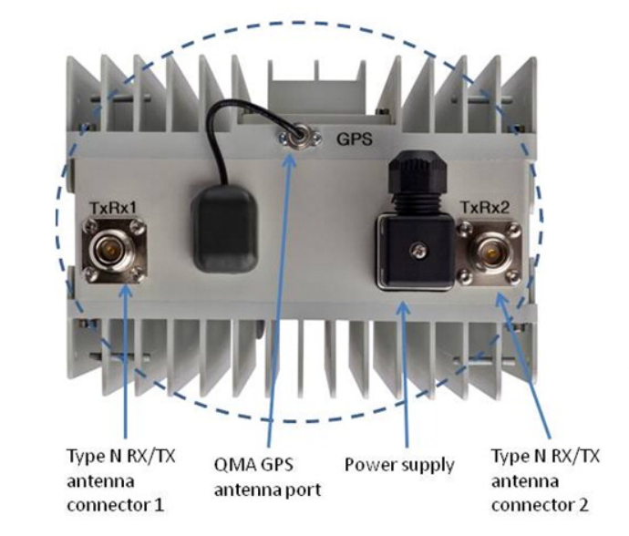
9764 CMCO B41 2x6W connection interfaces
The following figure shows the connection interfaces for the 9764 CMCO B41 2x6W.
Connection
location on 9764
CMCO
Interface Purpose
9764 CMCO B41
2x6W (Middle top)
QMA Connector to external
GPS antenna
Connection to the external GPS
antenna
9764 CMCO B41
2x6W ( Right top)
To the Power supply Connection AC or DC power source.
9764 CMCO B41
2x6W (Left/right top)
Type N antenna connectors RF antenna connectors
9764 CMCO B41
2x6W (bottom center
rear) backhaul
module
SFP to backhaul Backhaul and daisy chaining ports via
a backhaul module, either
•Dual SFP backhaul module
•SFP/PoE+ backhaul module
9764 CMCO (bottom
center rear) 1
To the optional 9764 MCO
Wi-Fi AP
Wi-Fi AP (optional) connector
Notes:
1. The 9764 CMCO B41 2x6W supports the attachment of the optional 9764 MCOWi-Fi AP.
Figure 2-6 9764 CMCO B41 2x6W connection interfaces
Product overview Physical description
....................................................................................................................................................................................................................................
....................................................................................................................................................................................................................................
2-10 Alcatel-Lucent – Proprietary
Use pursuant to applicable agreements
9764 CMCO B41 2x6W
3MN-02026-0001-RJZZA
Issue 0.01 March 2015
D
RAFT
D
RAFT
Power supply
The 9764 CMCO B41 2x6W requires an AC power feed (single phase, three-wire voltage
source in the 110-220V range), compliant with Telcordia GR-1089 Section 7 and IEC
60364-1 (IEC 60038 Annex A).
A power module unit inside the 9764 CMCO module provides AC/DC conversion (5.3V
output) to its power board, which then provides secondary DC-DC conversion and
distributes 5.3V (tolerance of +-3%) to the cube-based antennas, and the 9764 MCO
Wi-Fi AP module (if equipped).
A variant of the 9764 CMCO B41 2x6W supports -48 V DC power (nominal -48 V source
is in the range of -57 to -60 V DC).
RF Antenna
The 9764 CMCO B41 2x6W module supports either optional external antennas or an
optional Antenna Module which will be mounted via solar shield to the front of the
CMCO.
The two different antenna configurations allow an adaptation of the vertical beam width.
•Single Element Antenna Module (SEM-2600): 7.5 dBi typical gain, 80° H x 75° V
HPBW
•Dual Element Antenna Module (DEM-2600): 9.5 dBi typical gain, 80° H x 35° V
HPBW
Figure 2-7 Solar shield with attached antenna array
Product overview Physical description
....................................................................................................................................................................................................................................
....................................................................................................................................................................................................................................
9764 CMCO B41 2x6W
3MN-02026-0001-RJZZA
Issue 0.01 March 2015
Alcatel-Lucent – Proprietary
Use pursuant to applicable agreements 2-11
D
RAFT
D
RAFT
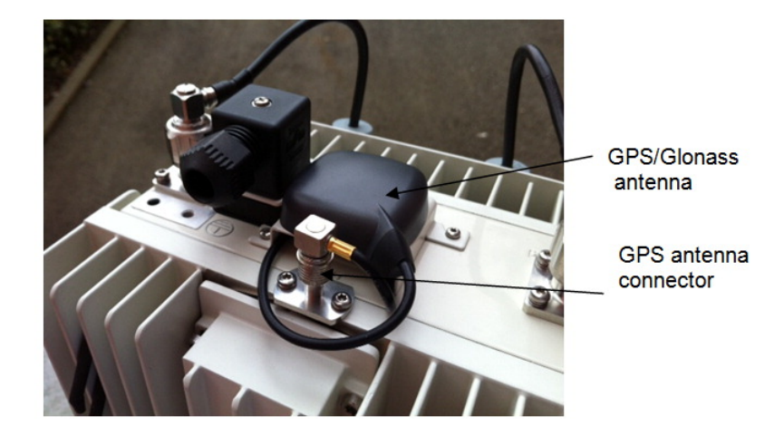
GPS Antenna
The 9764 CMCO B41 2x6W module is by default equipped with an external
GPS/Glonass antenna mounted on top and connected via a QMA connector to the internal
GPS Receiver (located on the modem board).
•Attached GPS/GLONASS antenna mounted on the top of the9764 CMCO B41 2x6W.
•Cabling to an external remote GPS antenna.
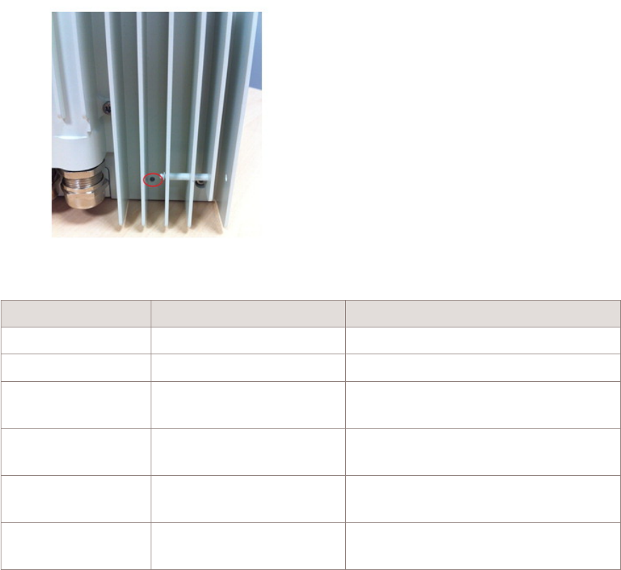
Status indicators
The 9764 CMCO B41 2x6W supports a single bi-color LED (red/green) which is located
on the rear lower portion of the casing. The LED is not intended for use during normal
operation of the equipment; however, it can provide a visual status of the equipment
during initial installation and commissioning.
Figure 2-8 9764 CMCO B41 2x6W with external GPS/Glonass antenna
Product overview Physical description
....................................................................................................................................................................................................................................
....................................................................................................................................................................................................................................
2-12 Alcatel-Lucent – Proprietary
Use pursuant to applicable agreements
9764 CMCO B41 2x6W
3MN-02026-0001-RJZZA
Issue 0.01 March 2015
D
RAFT
D
RAFT
LED Status LED description
Off Power off Power off
ON (Red) Initial state Power on or Restart
Blinking (Green) Software downloading
during system initialization
Software downloading
ON (Red) Failure 9764 CMCO LTE start-up or operational
failure
ON (Green) 9764 CMCO LTE becomes
operational
9764 CMCO LTE becoming operational
OFF 9764 CMCO LTE is
operational
9764 CMCO LTE has been in stable
operation for 15 minutes
Product labelling
The 9764 CMCO B41 2x6W product label provides the following labels:
A unit identification label reflecting:
•Vendor name/Icon
•Model name
•Part number
•Serial number
•CLEI code
•MAC address
Figure 2-9 LED position and orientation
Product overview Physical description
....................................................................................................................................................................................................................................
....................................................................................................................................................................................................................................
9764 CMCO B41 2x6W
3MN-02026-0001-RJZZA
Issue 0.01 March 2015
Alcatel-Lucent – Proprietary
Use pursuant to applicable agreements 2-13
D
RAFT
D
RAFT
•Power input range
•Data matrix barcode for Part number and Serial number
A regulatory label reflecting:
•Vendor name/Icon
•Product name
•Regulatory rules
•Power input
•Enclosure rating
•Applicable regulatory and environmental certification logos
•Manufacturer name
Product overview Physical description
....................................................................................................................................................................................................................................
....................................................................................................................................................................................................................................
2-14 Alcatel-Lucent – Proprietary
Use pursuant to applicable agreements
9764 CMCO B41 2x6W
3MN-02026-0001-RJZZA
Issue 0.01 March 2015
D
RAFT
D
RAFT

MCO weights and dimensions
Weights and dimensions
This topic covers the 9764 CMCO B41 2x6W weights and dimensions.
MRO weights and dimensions
The following table provides weights and dimensions for the 9764 CMCO B41 2x6W
with backhaul module but not including other ancillary items such as the 9764 MCO
Wi-Fi AP or mounting kits:
MRO configuration Weight Volume
(litres)
Overall dimensions (Length x
Width x Depth)
9764 CMCO B41
2x6W
7.3 kg (16.5 lb) 7.5 Liters 265 x 180 x 156.5 mm (10.4 x
7.09 x 6.16 in)
Product overview MCO weights and dimensions
....................................................................................................................................................................................................................................
....................................................................................................................................................................................................................................
9764 CMCO B41 2x6W
3MN-02026-0001-RJZZA
Issue 0.01 March 2015
Alcatel-Lucent – Proprietary
Use pursuant to applicable agreements 2-15
D
RAFT
D
RAFT
Supported installation options
Overview
The following section describes the supported installation options for the Alcatel-Lucent
9764 Compact Metro Cell Outdoor product. These include:
•Standard installation options for all 9764 CMCO products
•Daisy chain installation options where two 9764 CMCO modules are daisy chained
together and share the same backhaul port
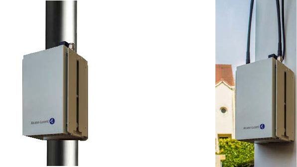
Standard installation options
The 9764 CMCO products are designed to be deployed outdoors and close to the users,
usually on light poles or lamp posts in streets or on building walls, with a vertical profile.
In addition, the 9764 CMCO can be fitted with an optional Alcatel-Lucent 9764 Metro
Cell Outdoor Wi-Fi AP.
Note: When deploying a Compact MCO with a remote Wi-Fi AP connected to the
POE interface, the antenna isolation between the Wi-Fi AP and the LTE antenna must
be at least -42 dB.
Refer to Alcatel-Lucent Small Cell Wi-Fi AP Technical Description, 3MN-01840-0004-
DEZZA for Wi-Fi AP product details.
Figure 2-10 Installation examples
Pole mount installation Wall mount installation
Product overview Supported installation options
....................................................................................................................................................................................................................................
....................................................................................................................................................................................................................................
2-16 Alcatel-Lucent – Proprietary
Use pursuant to applicable agreements
9764 CMCO B41 2x6W
3MN-02026-0001-RJZZA
Issue 0.01 March 2015
D
RAFT
D
RAFT
Urban furniture installation
The Alcatel-Lucent 9764 Compact Metro Cell Outdoor can be installed as part of urban
furniture, for example, bus shelter and information panels, to further improve the quality
of service provided to users in high density areas such as city centers.
Figure 2-11 9764 MCO Wi-Fi AP module attached to 9764 CMCO (front view)
Wi-Fi AP
Product overview Supported installation options
....................................................................................................................................................................................................................................
....................................................................................................................................................................................................................................
9764 CMCO B41 2x6W
3MN-02026-0001-RJZZA
Issue 0.01 March 2015
Alcatel-Lucent – Proprietary
Use pursuant to applicable agreements 2-17
D
RAFT
D
RAFT

Hardware and ancillary items
Overview
The following section lists the Alcatel-Lucent 9764 Compact Metro Cell Outdoor B41
2x6W base hardware equipment, the installation kits and ancillary items that can be
ordered from Alcatel-Lucent.
Box content
The product packaging contains the following content:
Alcatel-Lucent 9764 Compact Metro Cell Outdoor B41 2x6W:
•Backhaul Module (2 x SFP or PoE option)
•The Basic installation Kit Compact
•Mounting kits (Metro Compact Mounting Frame)
Table 2-1 9764 Compact Metro Cell Outdoor B41 2x6W
Item Description Use
9764 CMCO B41 TDD 2x6W
V2 AC
9764 CMCO B41 TDD 2x6W V2,
2500MHz, AC power
Qty: (1) per AC powered 9764 CMCO
B41 2x6W AC Module generic
9764 CMCO B41 TDD 2x6W
V2 DC
9764 CMCO B41 TDD 2x6W V2,
2500MHz, DC power
Qty: (1) per AC powered 9764 CMCO
B41 2x6W DC Module generic
Table 2-2 Backhaul Module
Item Description Use
Backhaul Module 2 x SFP Provides two SFP cages for backhaul
connection and Daisy Chain. Optical
and electrical SFPs are supported.
Mandatory
One backhaul module variant required per
9764 CMCO
Backhaul Module POE Provides one PoE+ capable RJ45
connector (for powering an external
PoE device) and one SFP cage. The
SFP cage supports optical and
electrical SFPs.
Table 2-3 Basic installation Kit Compact
Item Description Use
Basic installation kit for
compact
Basic installation kit for 9764 CMCO Mandatory for each 9764 CMCO
Qty: (1) per kit per 9764 CMCO
Product overview Hardware and ancillary items
....................................................................................................................................................................................................................................
....................................................................................................................................................................................................................................
2-18 Alcatel-Lucent – Proprietary
Use pursuant to applicable agreements
9764 CMCO B41 2x6W
3MN-02026-0001-RJZZA
Issue 0.01 March 2015
D
RAFT
D
RAFT

The following table list the mounting frame that are available for order from
Alcatel-Lucent in support of the equipment installation options.
Table 2-4 Mounting frame
Installation kit Description Use
Mounting Frame for 9764
CMCO
9764 Compact Metro Cell Outdoor
Mounting Frame
Mandatory:
•pole mount with tilt
•wall mount: with vertical only
•wall mount: with vertical and
horizontal tilt
Ancillary items
Ancillary equipment encompasses the orderable items (other than the 9764 CMCO
module) that, when installed together with the 9764 CMCO V2.2 B41 LTE 2x6W,
comprise a 9764 CMCO.
These ancillary items include:
•Solar shield (mandatory if compact antenna array / optional and packed in the same
box as the MCO)
•RF antennas (Metro Compact Antenna Array – needs a mandatory solar shield)
•Pole mounting kit
•External Surge Arrestor Kit (for electrical backhaul configuration)
•SFP modules (optical or electrical)
•Ethernet cables (optical or electrical)
•Power connectors and cables (either AC or DC)
•Metro Basic Installation Kit
•Optional remote located external GPS antenna, cable, and adaptor
•9764 MCO Wi-Fi AP module (attaches to the bottom of the 9764 CMCO V2.2 B41
LTE 2x6W)
Solar shield
The Solar Shield covers the front side of the 9764 CMCO and protect for direct sun load.
It is mandatory unless the 9764 CMCO is installed indoor or protected by any other box.
It acts also as an adapter plate for the CMCO Antenna arrays.
Product overview Hardware and ancillary items
....................................................................................................................................................................................................................................
....................................................................................................................................................................................................................................
9764 CMCO B41 2x6W
3MN-02026-0001-RJZZA
Issue 0.01 March 2015
Alcatel-Lucent – Proprietary
Use pursuant to applicable agreements 2-19
D
RAFT
D
RAFT

The solar shield is attached to the front side of the 9764 CMCO
Item Description Use
Solar shield Solar Shield for Compact MCO Optional
Mutually exclusive with “Antenna Array
mounted on solar shield”
Qty 1 per 9764 CMCO if required
RF antenna
Compact Metro Cell Antenna Array is designed to be mounted to the front of the 9764
CMCO. The antenna is attached to a solar shield. The Solar Shield acts as an adaptor
plate for the antenna.
Item Description Use
SU-MECAA41 (Single
antenna element)
Single antenna Array without solar
shield – 9764 CMCO for B41
Antenna Element without Solar Shield for
remote installation
Qty 1 per 9764 CMCO B41 if required
SU-AADEM26 (Dual antenna
element)
Dual antenna Array mounted on solar
shield – 9764 CMCO for B41
Antenna Element attached to Solar Shield,
for 9764 CMCO B41.
Note: Do not order additional solar shield
in this case
Qty 1 per 9764 CMCO B41 if required
SU-AASEM26 (Single
antenna element)
Single antenna Array mounted on
solar shield – 9764 CMCO for B41
External antenna - GPS
Item Description Use
GPS antenna External GPS Antenna, 1575
MHz*26 dBi
Used if 9764 CMCO is configured for
external GPS antenna and cable loss
<10dBi @ 1575MHz
GPS antenna External GPS Antenna, 1575
MHz*40 dBi
Used if 9764 CMCO is configured for
external GPS antenna and cable loss
>10dBi @ 1575MHz
KS-24577 List 8A: CONN,
RF PROTECTOR, GAS
TUBE, N
Surge suppressor for 26dBi GPS
antenna
Mandatory if a remote GPS antenna 26dBi
is required. (NAR-market)
(North America Regional markets)
KS-24577 List 8A: CONN,
RF PROTECTOR, GAS
TUBE, N
Surge suppressor for 26dBi GPS
antenna
Mandatory if a remote GPS antenna 26dBi
is required.
(International markets)
Jumper cable External GPS Antenna jumper cable
(2m, 5m, 15m)
Mandatory
1 cable per 9764 CMCO if external GPS
antenna is used (International markets)
Jumper cable External GPS Antenna jumper cable
(36ft, 60ft)
Mandatory
1 cable per 9764 CMCO if external GPS
antenna is used (North America Regional
markets)
Product overview Hardware and ancillary items
....................................................................................................................................................................................................................................
....................................................................................................................................................................................................................................
2-20 Alcatel-Lucent – Proprietary
Use pursuant to applicable agreements
9764 CMCO B41 2x6W
3MN-02026-0001-RJZZA
Issue 0.01 March 2015
D
RAFT
D
RAFT

Item Description Use
Adapter cable External GPS Antenna adaptor cable Mandatory
1 cable per 9764 CMCO if external GPS
antenna is used
Weatherproof kit Weatherproof tape, Vinyl electrical
tape, Linerless rubber splicing tape
Order these 3 items to protect the
connectors, if a remote GPS antenna is
required (only required for North America
Regional markets)
Mounting kits
The following table list the mounting kits that are available for order from Alcatel-Lucent
in support of the equipment installation options.
Table 2-5 Mounting kits
Installation kit Description Use
Vertical tilt installation kit Vertical tilt bracket Mandatory:
•pole mount with tilt
•wall mount: with vertical only
•wall mount: with vertical and
horizontal tilt
Horizontal tilt installation kit Horizontal tilt bracket Mandatory:
•wall mount: with horizontal tilt only
•wall mount: with horizontal and
vertical tilt
Banding kit Stainless steel bands
Band buckles (Ear-Lokt)
Mandatory:
•pole mount only
Banding tool Tool for metal band (BAND-IT) Mandatory:
•use with the Banding kit for pole
mount only
•1 per installation team.
Surge arrestor
If GBE 1000BaseT is used, it’s highly recommended to use an optional Ethernet Surge
Arrestor. The GBE ports within the 9764 CMCO provide no surge protection for backhaul
connection.
Item Description Use
Surge arrestor External Ethernet surge arrestor Optional
Highly recommended if GBE 1000BaseT
backhaul connection is provided
Product overview Hardware and ancillary items
....................................................................................................................................................................................................................................
....................................................................................................................................................................................................................................
9764 CMCO B41 2x6W
3MN-02026-0001-RJZZA
Issue 0.01 March 2015
Alcatel-Lucent – Proprietary
Use pursuant to applicable agreements 2-21
D
RAFT
D
RAFT

Item Description Use
Surge arrestor kit External Ethernet surge arrestor kit,
including:
•mounting bracket for pole/wall
•Metal band and buckle ear for
pole mounting
•Ethernet cable outdoor (0,6m)
for interconnection of 9764
CMCO and Surge Arrestor
Required for External surge arrestor
SFP modules
The 9764 CMCO provides two SFP cages. Depending on the backhaul interface provided
for connecting the 9764 CMCO the proper SFP must be inserted in the SFP cage.
Item Description Use
SFP module SFP GBE 10/100/1000BaseT
(copper)
Optional
Electrical backhaul only
SFP module SFP GBE 1000BaseLX (Single
mode)
Optional
Optical backhaul, Daisy chaining
SFP module SFP GBE 1000BaseLX / CPRI
(Single mode)
Optional
Optical backhaul, Daisy chaining
SFP module SFP GBE 1000BaseSX / CPRI (Multi
mode)
Optional
Optical backhaul, Daisy chaining
SFP module GPON SFP Optional
Optical backhaul only
Ethernet cable - Electrical
Item Description Use
Electrical Ethernet cable 2m, 25m, 100m outdoor, 4 pairs, 2
RJ45 (plus 1 spare)
Optional
Use with SFP GBE 10/100/1000BaseT
(International markets)
Electrical Ethernet cable 2m, 25m, 100m outdoor, 4 pairs, 2
RJ45 (plus 1 spare)
Optional
Use with SFP GBE 10/100/1000BaseT
(North America Regional markets)
Product overview Hardware and ancillary items
....................................................................................................................................................................................................................................
....................................................................................................................................................................................................................................
2-22 Alcatel-Lucent – Proprietary
Use pursuant to applicable agreements
9764 CMCO B41 2x6W
3MN-02026-0001-RJZZA
Issue 0.01 March 2015
D
RAFT
D
RAFT

Ethernet cable - Optical
Item Description Use
Fiber Optic cable SMDF LC-LC 2SM 1m Optional
Single mode fiber duplex. 80mm/80mm
Breakout, Outer diameter: 5.5mm
Use for Single Mode link (select cable
length)
Fiber Optic cable SMDF LC-LC 2SM 2.5m
Fiber Optic cable SMDF LC-LC 2SM 5m
Fiber Optic cable SMDF LC-LC 2SM 10m
Fiber Optic cable SMDF LC-LC 2SM 15m
Fiber Optic cable SMDF LC-LC 2SM 30m
Fiber Optic cable SMDF LC-LC 2SM 50m
Fiber Optic cable SMDF LC-LC 2SM 70m
Fiber Optic cable SMDF LC-LC 2SM 85m
Fiber Optic cable SMDF LC-LC 2SM 100m
Fiber Optic cable SMDF LC-LC 2SM 150m
Fiber Optic cable SMDF LC-LC 2SM 200m
Fiber Optic cable SMDF LC-LC 2SM 250m
Fiber Optic cable SMDF LC-LC 2SM 300m
Fiber Optic cable MM LC-LC 2MM 1m Optional
Multi Mode fiber duplex. 80mm/80mm
Breakout, Outer diameter: 5.5mm
Use for Multi Mode link (select cable
length)
Fiber Optic cable MM LC-LC 2MM 2.5m
Fiber Optic cable MM LC-LC 2MM 5m
Fiber Optic cable MM LC-LC 2MM 10m
Fiber Optic cable MM LC-LC 2MM 15m
Fiber Optic cable MM LC-LC 2MM 30m
Fiber Optic cable MM LC-LC 2MM 50m
Fiber Optic cable MM LC-LC 2MM 70m
Fiber Optic cable MM LC-LC 2MM 85m
Fiber Optic cable MM LC-LC 2MM 100m
Fiber Optic cable MM LC-LC 2MM 150m
Fiber Optic cable MM LC-LC 2MM 200m
Fiber Optic cable MM LC-LC 2MM 250m
Fiber Optic cable MM LC-LC 2MM 300m
Product overview Hardware and ancillary items
....................................................................................................................................................................................................................................
....................................................................................................................................................................................................................................
9764 CMCO B41 2x6W
3MN-02026-0001-RJZZA
Issue 0.01 March 2015
Alcatel-Lucent – Proprietary
Use pursuant to applicable agreements 2-23
D
RAFT
D
RAFT

Ethernet cable - Optical for GPON
Item Description Use
Fiber Optic cable SM SC-PC 1SM OFNR-LS BK75 4m Optional
Single mode fiber simlex. 75mm/75mm
Breakout
Rules: required for GPON link
Qty: (1) per GPN link. Select fiber of
length required
Fiber Optic cable SC-PC 1SM OFNR-LS BK75 8m
Fiber Optic cable SM SC-PC 1SM OFNR-LS BK75
12m
Power
Item Description Use
Power connector (AC) AC power connector Required for 9764 CMCO module with
AC power (International markets)
Power connector (DC) DC power connector Required for 9764 CMCO module with
DC power (International markets)
Power cable Power cable IN/OUT 3G1,5mm²,
100m roll or multiples of 1m length
(as needed)
Required for 9764 CMCO module
(International markets)
Power cable (AC) Power cable pre-assembled with AC
power connector, various lengths
(2m. 4.5m, 9m, 12m)
Required for 9764 CMCO module with
AC power (North America Regional
markets)
Power cable (DC) Power cable pre-assembled with DC
power connector, various lengths
(2m. 4.5m, 9m, 12m)
Required for 9764 CMCO module with
DC power (North America Regional
markets)
Note: For Non-NAR appropriate power connector (AC or DC) needs to be selected,
NAR specific power cables are prefab cables and already assembled with power
connectors.
Grounding
Item Description Use
Ground cable Ground cable,Y/G 10mm² in 100m
roll
Required for International markets
Ground cable Ground cable, 8 AWG Required for North America Regional
markets
Product overview Hardware and ancillary items
....................................................................................................................................................................................................................................
....................................................................................................................................................................................................................................
2-24 Alcatel-Lucent – Proprietary
Use pursuant to applicable agreements
9764 CMCO B41 2x6W
3MN-02026-0001-RJZZA
Issue 0.01 March 2015
D
RAFT
D
RAFT

33Basic site preparation
requirements
Overview
Purpose
This chapter describes basic site preparation requirements before installation of the
Alcatel-Lucent 9764 Compact Metro Cell Outdoor B41 2x6W.
Contents
Environmental and mechanical specifications 3-2
Site requirements 3-4
Installation clearances 3-5
Pole mount requirements 3-6
Wall mount requirements 3-8
...................................................................................................................................................................................................................................
9764 CMCO B41 2x6W
3MN-02026-0001-RJZZA
Issue 0.01 March 2015
Alcatel-Lucent – Proprietary
Use pursuant to applicable agreements 3-1
D
RAFT
D
RAFT

Environmental and mechanical specifications
Environmental and mechanical specifications
Temperature range:
Normal operation -40°C to +50°C
+ solar exposure (+55°C with solar shield)
Cold start-up -33°C
Humidity:
Condensing 5% to 100%
Altitude:
Altitude range 0-1800 m (6000 feet) above sea level
Vibration:
North American Region (NAR) GR-63-CORE Sections 4.4.4 & 5.4.2
GR-487-CORE Section 3.35
European Union (EU) ETS 300-019-1.4 class 4.1E
Earthquake Richter scale 7
Corrosion:
Salt fog testing GR-487-CORE section 3.34.1
IEC 60068-2-52
EMC/EMI/safety/RF exposure:
Emissions FCC part 24 CFR 24.238
Emission limits FCC part 27 CFR 27.54
Conducted spurious radiated
emissions
GR-1089 section 3.22 and 3.2.3
FCC part 15 subpart B class B
ETSI TS 136 113
EMC directive 2004/108/EC
Immunity to radiation FCC part 15 subpart A class B
ETSI TS 136 113
ETSI TS 136 113 GR-1089 section 2.1.2
Safety CAN/CSA-C22.2 NO. 60950-1-07 / UL 60950-1
RF exposure US FCC 47CFR 1.1310, US FCC OET65 (including
supplements), Canada Safety Code 6, Canada RSS 102.
Environment:
Basic site preparation requirements Environmental and mechanical specifications
....................................................................................................................................................................................................................................
....................................................................................................................................................................................................................................
3-2 Alcatel-Lucent – Proprietary
Use pursuant to applicable agreements
9764 CMCO B41 2x6W
3MN-02026-0001-RJZZA
Issue 0.01 March 2015
D
RAFT
D
RAFT

ROHS ROHS directive 6 of 6 ref E3
Hazardous material WEEE directive 2002/95/EC
Recycling WEEE directive 2002/96/EC
Basic site preparation requirements Environmental and mechanical specifications
....................................................................................................................................................................................................................................
....................................................................................................................................................................................................................................
9764 CMCO B41 2x6W
3MN-02026-0001-RJZZA
Issue 0.01 March 2015
Alcatel-Lucent – Proprietary
Use pursuant to applicable agreements 3-3
D
RAFT
D
RAFT
Site requirements
Device placement
Before installing the 9764 CMCO B41 2x6W, you should perform a site survey to
determine the optimum use of the equipment and to maximize range, coverage, and
network performance.
The 9764 CMCO B41 2x6W is designed to be mounted on poles or walls in a central
location within the public spaces. Clear or open areas (where structures, trees, or hills do
not obstruct radio signals to and from the equipment) will provide better performance
than closed or filled areas.
General requirements
The following general requirements must be met before the installation of the 9764
CMCO B41 2x6W can begin:
•Adequate clearance must be provided for service access
•Power service must be installed
•Back haul facilities must be installed
•Grounding electrode system must be installed
•The environment must comply with stated environment requirements
•Mounting bracket holes must be drilled
•Where local regulations dictate, cable conduits must be prepared.
Structural requirements
Various building materials and construction methods dictate that equipment must be
fastened to a wall/pole with appropriate mounting hardware. It is the responsibility of the
customer to provide any necessary support material and structures to ensure that the
installation will be in compliance with national building codes and all other applicable
codes.
Basic site preparation requirements Site requirements
....................................................................................................................................................................................................................................
....................................................................................................................................................................................................................................
3-4 Alcatel-Lucent – Proprietary
Use pursuant to applicable agreements
9764 CMCO B41 2x6W
3MN-02026-0001-RJZZA
Issue 0.01 March 2015
D
RAFT
D
RAFT
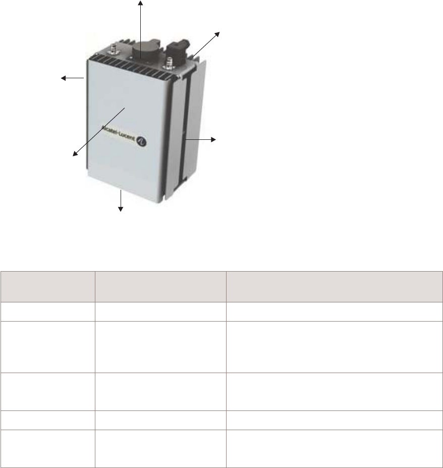
Installation clearances
Minimum installation clearances
The following provides the minimum wall mount clearances recommended around the
9764 CMCO B41 2x6W.
Metro Cell
Outdoor
Clearances mm
(inches)
Comment
Side(s) 400 mm (15.75 inch) Access to secure the solar shield cover.
Top 400 mm (15.75 inch) Access to cable connections and cable
bending radius.
To aid natural air convection.
Bottom 400 mm (15.75 inch) Access to connections (Wi-Fi AP).
To aid natural air convection.
Front 460 mm (18.11 inch) Access to secure the solar shield cover.
Rear 20 mm (0.79 inch) For the wall mounting space.
To aid natural air convection.
Figure 3-1 9764 CMCO B41 2x6W installation clearances
Rear clearance
20mm (0.79in)
Front clearance
460mm (18.11in)
Bottom clearance
400mm (15.75in)
Side clearance
400mm (15.75 in)
Top clearance
400mm (15.75in)
Side clearance
400mm (15.75 in)
Basic site preparation requirements Installation clearances
....................................................................................................................................................................................................................................
....................................................................................................................................................................................................................................
9764 CMCO B41 2x6W
3MN-02026-0001-RJZZA
Issue 0.01 March 2015
Alcatel-Lucent – Proprietary
Use pursuant to applicable agreements 3-5
D
RAFT
D
RAFT

Pole mount requirements
Purpose
This topic outlines the basic requirements, installation kits and recommended anchor
materials when mounting the 9764 CMCO B41 2x6W Outdoor directly onto a pole, onto
tilt brackets or onto a pair mount bracket.
Pole mount options
The 9764 CMCO can be easily mounted onto a pole for the following installation options:
•9764 CMCO banded onto a pole (without the tilt option).
The 9764 CMCO mounting bracket and pole band installation kit is used.
•9764 CMCO attached to the vertical tilt bracket. Vertical tilt bracket is banded onto a
pole.
The vertical tilt bracket, 9764 CMCO mounting bracket and pole band installation kit
is used.
Pole mount installation kits and brackets
The following table provides the installation kits and brackets that can be used, depending
on the deployment scenario, for 9764 CMCO pole mounting.
Table 3-1 Pole mount installation kits and brackets
Item Description
9764 MCO Compact mounting bracket Required for attaching the 9764 CMCO directly onto a pole or vertical tilt
bracket
Vertical tilt bracket Provides +/- 30° vertical tilt (up/down) adjustment
Banding kit Required when directly attaching the 9764 CMCO or vertical tilt bracket
to a pole (diameter 50 to 300 mm) using stainless steel bands.
Stainless steel bands and buckles (Ear-Lokt)
Banding tool Standard BAND-IT®Banding Tool, including operating instructions
Required in order to tighten stainless steel metal bands
The following figure shows the brackets used for pole mount installation, depending on
the deployment scenario.
Basic site preparation requirements Pole mount requirements
....................................................................................................................................................................................................................................
....................................................................................................................................................................................................................................
3-6 Alcatel-Lucent – Proprietary
Use pursuant to applicable agreements
9764 CMCO B41 2x6W
3MN-02026-0001-RJZZA
Issue 0.01 March 2015
D
RAFT
D
RAFT
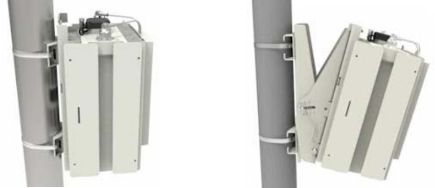
Figure 3-2 Pole mount banding and brackets
Pole mount no tilt Pole mount with tilt
Basic site preparation requirements Pole mount requirements
....................................................................................................................................................................................................................................
....................................................................................................................................................................................................................................
9764 CMCO B41 2x6W
3MN-02026-0001-RJZZA
Issue 0.01 March 2015
Alcatel-Lucent – Proprietary
Use pursuant to applicable agreements 3-7
D
RAFT
D
RAFT

Wall mount requirements
Purpose
This topic outlines the basic requirements when installing the Alcatel-Lucent 9764
Compact Metro Cell Outdoor B41 2x6W onto a solid concrete wall or flat surface.
Wall mount options
The 9764 CMCO can be easily mounted onto any flat, sturdy wall for the following
installation options:
•9764 CMCO attached directly onto a wall or flat surface.
•9764 CMCO attached to the vertical/horizontal tilt bracket(s). Vertical/horizontal tilt
bracket(s) are attached to a wall.
Wall mount installation brackets and kits
The following table lists the installation brackets that can be used, depending on the
deployment scenario, for 9764 CMCO wall mounting.
Table 3-2 Wall mount installation brackets
Item Description
9764 CMCO mounting bracket Required when attaching the 9764 CMCO directly to a wall or flat surface
or onto tilt brackets.
Vertical tilt bracket Provides +/- 30° vertical tilt (up/down) adjustment
Note: Can be used in combination with the horizontal installation kit to
provide:
•+/- 30° vertical tilt (up/down) adjustment, and
•+/-45° horizontal tilt (left/right) adjustment
Horizontal tilt bracket Provides +/-45° horizontal tilt (left/right) adjustment
Note: Can be used in combination with the vertical tilt installation kit to
provide:
•+-45° horizontal tilt (left/right) adjustment, and
•+/- 30° vertical tilt (up/down) adjustment
Wall mount installation examples
The following figures show examples of 9764 CMCO wall mount installation and wall
mount installation with horizontal/vertical tilt.
Basic site preparation requirements Wall mount requirements
....................................................................................................................................................................................................................................
....................................................................................................................................................................................................................................
3-8 Alcatel-Lucent – Proprietary
Use pursuant to applicable agreements
9764 CMCO B41 2x6W
3MN-02026-0001-RJZZA
Issue 0.01 March 2015
D
RAFT
D
RAFT
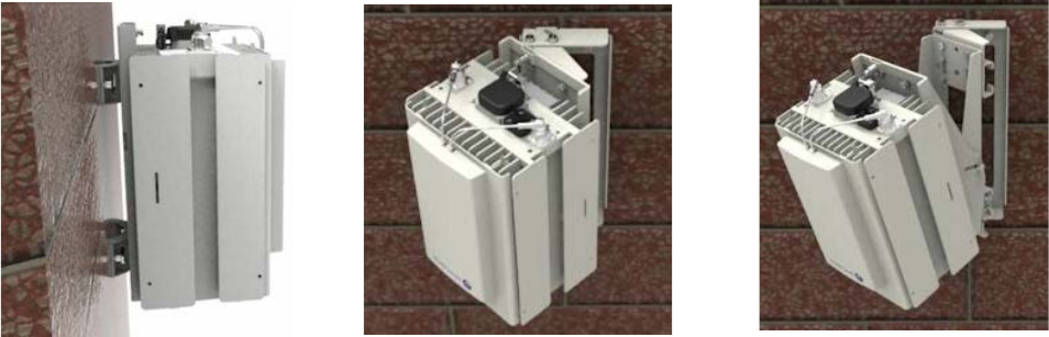
Figure 3-3 9764 CMCO wall mount examples
Wall mount no tilt Wall mount horizontal tilt only Wall mount horizontal
and vertical tilt
Basic site preparation requirements Wall mount requirements
....................................................................................................................................................................................................................................
....................................................................................................................................................................................................................................
9764 CMCO B41 2x6W
3MN-02026-0001-RJZZA
Issue 0.01 March 2015
Alcatel-Lucent – Proprietary
Use pursuant to applicable agreements 3-9
D
RAFT
D
RAFT
Basic site preparation requirements Wall mount requirements
....................................................................................................................................................................................................................................
....................................................................................................................................................................................................................................
3-10 Alcatel-Lucent – Proprietary
Use pursuant to applicable agreements
9764 CMCO B41 2x6W
3MN-02026-0001-RJZZA
Issue 0.01 March 2015
D
RAFT
D
RAFT

44Grounding and lightning
protection requirements
Overview
Purpose
This chapter provides information on grounding and lightning protection requirements
that need to be in place at the site prior to installation of the Alcatel-Lucent 9764
Compact Metro Cell Outdoor B41 2x6W.
Contents
Grounding and lightning protection 4-2
Product grounding 4-4
...................................................................................................................................................................................................................................
9764 CMCO B41 2x6W
3MN-02026-0001-RJZZA
Issue 0.01 March 2015
Alcatel-Lucent – Proprietary
Use pursuant to applicable agreements 4-1
D
RAFT
D
RAFT
Grounding and lightning protection
Overview
The primary goal of an earthing system is to assure personnel safety and protection of
installations against damage. Two important phenomena are lightning and power system
faults. These can cause circulation of large currents, which may create hazardous voltages
in the installation.
•For lightning, the task of the earthing system is to provide a path to the soil for
dangerous currents, while maintaining potential differences between any two points of
an installation as low as possible.
•For power system faults, it provides a safe path for fault currents, while also
maintaining potential differences between any two points of an installation as low as
possible.
Codes and standards
Regulatory grounding codes and standards may differ from region to region and country
to country. The grounding/bonding of the installation site and Alcatel-Lucent 9764 Metro
Cell Outdoor must follow national and/or local regulatory codes and standards in
countries and localities where these exist.
Examples of these regulatory codes and standards are:
•National Electric Code (NFPA 70), USA
•Canadian Electrical Code, Part I (CSA C22.1)
•BS 7671 (UK IEE Wiring Regulations, BS 7671
•VDE 0100, Germany
•International Electrotechnical Commission's international standard, 60364
Grounding requirements
The Alcatel-Lucent 9764 Metro Cell Outdoor can be susceptible to lightning surges due to
its association with elevated installation locations. It is therefore imperative that the
equipment and installation site be properly grounded to a reliable and effective grounding
electrode system such that a low impedance path to earth is provided.
For Alcatel-Lucent 9764 Metro Cell Outdoor installations the following grounding system
types are supported:
•TN
In a TN earthing system, one of the points in the generator or transformer is connected
with earth, usually the star point in a three-phase system. The body of the electrical
device is connected with earth via this earth connection at the transformer.
•TT
Grounding and lightning protection requirements Grounding and lightning protection
....................................................................................................................................................................................................................................
....................................................................................................................................................................................................................................
4-2 Alcatel-Lucent – Proprietary
Use pursuant to applicable agreements
9764 CMCO B41 2x6W
3MN-02026-0001-RJZZA
Issue 0.01 March 2015
D
RAFT
D
RAFT
In a TT earthing system, the protective earth connection of the consumer is provided
by a local connection to earth, independent of any earth connection at the generator.
Important! Where uncertainty exists around the reliability and/or effectiveness of the
main grounding system contact Alcatel-Lucent Technical Support or the appropriate
electrical inspection authority.
In addition the following document can also be used as a general reference for
installation site grounding requirements, Grounding and Lightning Protection
Guidelines for Wireless System Cell Sites, 401-200-115.
Surge protection requirements
Having a good ground alone is not enough to minimize damage due to energy surges.
Commercial power and data facilities are susceptible to lightning surges, switching
transients of power and switching of circuit breakers in the power system under fault
conditions. Therefore power and data facilities must be also be properly protected.
A surge protection device capable of discharging the surge waveforms as defined in IEEE
C62.41 (1991), Recommended Practice on Surge Voltage in Low-Voltage AC Power
Circuits, for Location Category “C3” and “High System Exposure” must be installed in
the power panel board or load center supplying power to the installation site and must be
connected directly to the grounding electrode system. The power panel board or load
center, circuit breakers and surge protector are not supplied with the product. They must
be ordered and installed as part of site preparation by the customer.
It is also strongly recommended that surge protection devices are installed on electrical
data facilities cabling in order to protect against electrical surges that may potentially
cause damage to equipment and the cables if they were not adequately protected.
Grounding and lightning protection requirements Grounding and lightning protection
....................................................................................................................................................................................................................................
....................................................................................................................................................................................................................................
9764 CMCO B41 2x6W
3MN-02026-0001-RJZZA
Issue 0.01 March 2015
Alcatel-Lucent – Proprietary
Use pursuant to applicable agreements 4-3
D
RAFT
D
RAFT
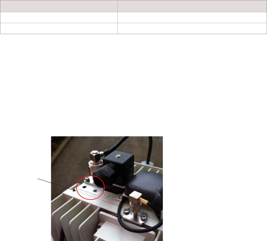
Product grounding
Overview
This section details the grounding ancillary items and grounding connection points on the
Alcatel-Lucent 9764 Compact Metro Cell Outdoor B41 2x6W.
Grounding ancillary items
The following grounding related ancillary items can be ordered from Alcatel-Lucent.
Table 4-1 Grounding materials
Item Description
Grounding cable Green and yellow insulation (100 meter roll)
Basic installation kit Cable lugs, screws and washers
Note: Where grounding materials are locally supplied it is important that all
grounding system material (cable, connectors, buses, etc.) are of high quality, that
resist deterioration and require little or no maintenance.
9764 CMCO grounding point
The following figure shows the grounding point on the 9764 CMCO. The ground cable
can be connected directly to the 9764 CMCO via a double hole grounding lug crimped
onto the cable. M5 screws are used to attach the ground cable to the grounding point on
the 9764 CMCO.
Double lug
ground point
Grounding and lightning protection requirements Product grounding
....................................................................................................................................................................................................................................
....................................................................................................................................................................................................................................
4-4 Alcatel-Lucent – Proprietary
Use pursuant to applicable agreements
9764 CMCO B41 2x6W
3MN-02026-0001-RJZZA
Issue 0.01 March 2015
D
RAFT
D
RAFT

55Electrical power
requirements
Overview
Purpose
This chapter provides guidelines for the installation of electrical power to the
Alcatel-Lucent 9764 Compact Metro Cell Outdoor B41 2x6W.
Contents
Site power requirements (AC) 5-2
Site power requirements (DC) 5-5
Product power requirements 5-8
...................................................................................................................................................................................................................................
9764 CMCO B41 2x6W
3MN-02026-0001-RJZZA
Issue 0.01 March 2015
Alcatel-Lucent – Proprietary
Use pursuant to applicable agreements 5-1
D
RAFT
D
RAFT
Site power requirements (AC)
Purpose
This section describes the power and grounding requirements that must be considered
when planning site facilities for Alcatel-Lucent installed equipment and products.
General requirements
All power and grounding system wiring, short-circuit (over-current) protection and surge
protection devices must be installed by the appropriately licensed personnel. Installation
must be performed in accordance with national and local electrical codes, for example:
•In the United States:
National Electrical Code, NFPA 70
•In Canada:
Canadian Electrical Code, part I, CSA C22.1
•In other countries:
International Electrotechnical Commission (IEC) 60364, parts 1 through 7
In addition, adherence to all additional requirements mandated by the “country of use” is
the customer's responsibility.
The appropriate power supply ground connections and site equipment ground connections
must be in place before commercial AC power service can be connected to the equipment
installed at the site.
Customer AC power supply
The equipment installed on site must be supported with a customer supplied AC power
service. The AC connection point should be easily accessible by the service team and be
marked as the disconnect device of the equipment.
Note:
•The service board (or load center), circuit breakers and surge protectors devices
are not supplied with the product. They must be ordered and installed as part of
site preparation by the customer.
•All wiring (including grounding) and over-current protection must be installed at
the service panel by suitably trained and licensed personnel and in accordance
with the national and local electrical codes.
•An appropriate earth ground connection is required before commercial power
service can be connected to any equipment at the site.
In the United States and Canada, the branch circuit breaker shall be installed in
accordance with the National Electrical Code, or the Canadian Electrical Code, Part I.
Electrical power requirements Site power requirements (AC)
....................................................................................................................................................................................................................................
....................................................................................................................................................................................................................................
5-2 Alcatel-Lucent – Proprietary
Use pursuant to applicable agreements
9764 CMCO B41 2x6W
3MN-02026-0001-RJZZA
Issue 0.01 March 2015
D
RAFT
D
RAFT
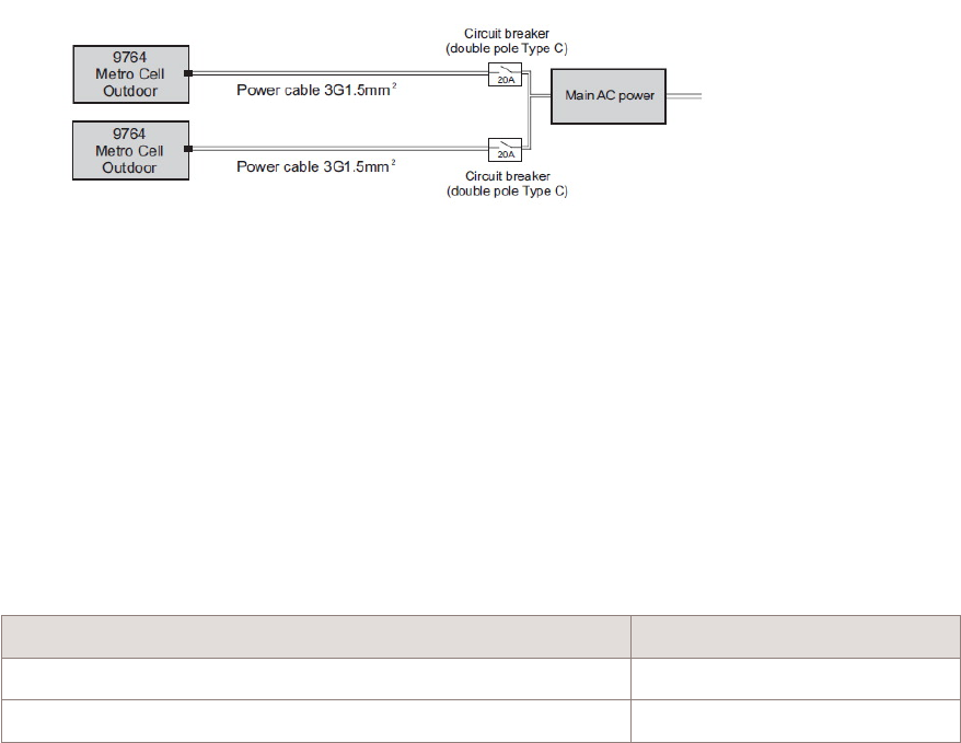
The branch circuit breaker should always be situated upstream of the equipment and must
be a double pole 20A Type C disconnect device.
Line surge protection
A surge protection device is not supplied with the product. It must be ordered and
installed as part of site preparation by the customer.
The equipment can be connected to an AC mains distribution system classified as CAT II
(equipment dedicated for connection to the mains distributed within a building). If the
category of the AC mains is higher than CAT II (III or IV), then upstream surge protection
must be installed by the customer to reduce the voltage range of transients in accordance
with CAT II.
Power source Over-voltage category
Equipment connected to building mains CAT II
Equipment connected directly to low voltage mains CAT III or CAT IV
The installation wiring for all outdoor AC units must be provided with a Listed/Approved
surge protection device. In the United States and Canada the installation must be in
accordance with the National Electrical Code or the Canadian Electrical Code, Part I.
Power junction box
For outdoor installations, in countries where local regulations dictate, a customer-supplied
power junction box, or a mating plug and receptacle, may need to be installed as part of
site preparation. As part of site preparation, the customer must provide the appropriate
junction box and associated fittings.
In the United States and Canada, outdoor cord pendants, if used, shall comply with NEC
Article 400 or Canadian Electrical Code, Part I Rule 4-012
Electrical power requirements Site power requirements (AC)
....................................................................................................................................................................................................................................
....................................................................................................................................................................................................................................
9764 CMCO B41 2x6W
3MN-02026-0001-RJZZA
Issue 0.01 March 2015
Alcatel-Lucent – Proprietary
Use pursuant to applicable agreements 5-3
D
RAFT
D
RAFT
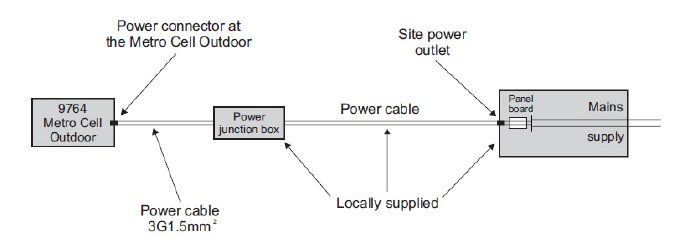
Conduit requirements
For outdoor installations, in countries where local regulations dictate, the power cables
are required to be routed to the equipment within rigid metal conduit (RMC) or
liquid-tight flexible metal (LTFMC) conduit. As part of site preparation, the customer
must provide the metal conduit and associated fittings for cable routes and connecting
conduit to the outdoor equipment.
Alternatively, an allowable outdoor armored cable described in the National Electrical
Code and Canadian Electrical Code, Part I, may be used without a conduit.
Cable types that may be used without a conduit include:
•Type MC cable, such as Hybriflex cable
•Outdoor tray cable Type TC-ER
Electrical power requirements Site power requirements (AC)
....................................................................................................................................................................................................................................
....................................................................................................................................................................................................................................
5-4 Alcatel-Lucent – Proprietary
Use pursuant to applicable agreements
9764 CMCO B41 2x6W
3MN-02026-0001-RJZZA
Issue 0.01 March 2015
D
RAFT
D
RAFT
Site power requirements (DC)
Purpose
This section describes the power and grounding requirements that must be considered
when planning site facilities for Alcatel-Lucent installed equipment and products.
General requirements
All power and grounding system wiring, short-circuit (over-current) protection and surge
protection devices must be installed by the appropriately licensed personnel. Installation
must be performed in accordance with national and local electrical codes, for example:
•In the United States:
United States National Fire Protection Association (NFPA) 70 and United States
National Electrical Code (NEC)
•In Canada:
Canadian Electrical Code, part I, CSA C22.1
•In other countries:
International Electrotechnical Commission (IEC) 60364, parts 1 through 7
In addition, adherence to all additional requirements mandated by the “country of use” is
the customer's responsibility.
The appropriate power supply ground connections and site equipment ground connections
must be in place before commercial AC power service can be connected to the equipment
installed at the site.
Customer DC power supply
The equipment installed on site must be supported with a customer supplied nominal
-48V DC power service. The DC connection point should be easily accessible by the
service team and be marked as the disconnect device of the equipment.
Note:
•The service board (or load center), circuit breakers and surge protectors devices
are not supplied with the product. They must be ordered and installed as part of
site preparation by the customer.
•All wiring (including grounding) and over-current protection must be installed at
the service panel by suitably trained and licensed personnel and in accordance
with the national and local electrical codes.
•An appropriate earth ground connection is required before commercial power
service can be connected to any equipment at the site.
Electrical power requirements Site power requirements (DC)
....................................................................................................................................................................................................................................
....................................................................................................................................................................................................................................
9764 CMCO B41 2x6W
3MN-02026-0001-RJZZA
Issue 0.01 March 2015
Alcatel-Lucent – Proprietary
Use pursuant to applicable agreements 5-5
D
RAFT
D
RAFT
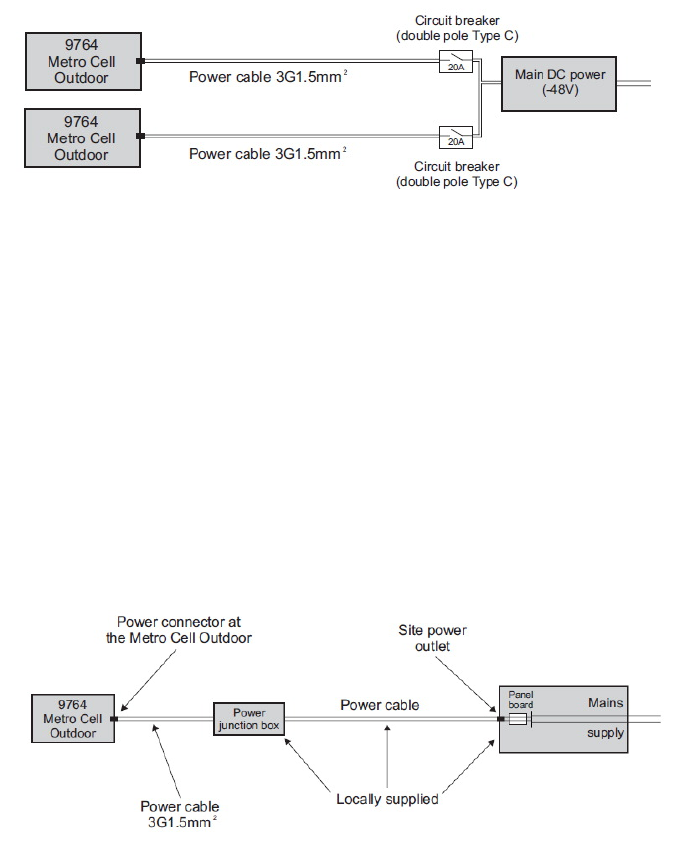
The branch circuit breaker should always be situated upstream of the equipment and must
be a double pole 20A Type C disconnect device.
Line surge protection
A surge protection device is not supplied with the product. It must be ordered and
installed as part of site preparation by the customer.
Power junction box
For outdoor installations, in countries where local regulations dictate, a customer supplied
power junction box may need to be installed as part of site preparation. As part of site
preparation, the customer must provide the appropriate junction box and associated
fittings.
In the United States and Canada, outdoor cord pendants, if used, shall comply with NEC
Article 400 or Canadian Electrical Code, Part I Rule 4-012.
Conduit requirements
For outdoor installations, in countries where local regulations dictate, the power cables
are required to be routed to the equipment within rigid metal conduit (RMC) or
liquid-tight flexible metal (LTFMC) conduit. As part of site preparation, the customer
must provide the metal conduit and associated fittings for cable routes and connecting
conduit to the outdoor equipment.
Electrical power requirements Site power requirements (DC)
....................................................................................................................................................................................................................................
....................................................................................................................................................................................................................................
5-6 Alcatel-Lucent – Proprietary
Use pursuant to applicable agreements
9764 CMCO B41 2x6W
3MN-02026-0001-RJZZA
Issue 0.01 March 2015
D
RAFT
D
RAFT
Alternatively, an allowable outdoor armored cable described in the National Electrical
Code and Canadian Electrical Code, Part I, may be used without a conduit.
Cable types that may be used without a conduit include:
•Type MC cable, such as Hybriflex cable
•Outdoor tray cable Type TC-ER
Electrical power requirements Site power requirements (DC)
....................................................................................................................................................................................................................................
....................................................................................................................................................................................................................................
9764 CMCO B41 2x6W
3MN-02026-0001-RJZZA
Issue 0.01 March 2015
Alcatel-Lucent – Proprietary
Use pursuant to applicable agreements 5-7
D
RAFT
D
RAFT

Product power requirements
Product power data
The 9764 CMCO B41 2x6W requires an AC power feed (single phase, three-wire voltage
source in the 110-220V range), compliant with Telcordia GR-1089 Section 7 and IEC
60364-1 (IEC 60038 Annex A). A power module unit inside the 9764 CMCO module
provides AC/DC conversion (5.3V output) to its power board, which then provides
secondary DC-DC conversion and distributes 5.3V (tolerance of +-3%) to the cube-based
antennas, and the 9764 MCO Wi-Fi AP module (if equipped).
The following table provides power related information applicable to the 9764 CMCO
B41 2x6W.
Power supply
AC power 110 to 220 VAC, single phase, 2 A,
50/60 Hz
DC power nominal -48 V DC, range (-57V ~
-60V DC)
Power consumption
Average consumption 150W
Peak consumption 170W
Power ancillary items
The following Alcatel-Lucent power related ancillary items must be used.
Table 5-1 Power materials
Item Description Use
Power connector (AC) AC power connector Required for 9764 CMCO with AC power
(International markets)
Power connector (DC) DC power connector Required for 9764 CMCO with DC power
(International markets)
Power cable Power cable IN/OUT 3G1,5mm²,
100m roll or multiples of 1m length
(as needed)
Required for 9764 CMCO (International
markets)
Power cable (AC) Power cable pre-assembled with AC
power connector, various lengths
(2m. 4.5m, 9m, 12m)
Required for 9764 CMCO with AC power
(North America Regional markets)
Electrical power requirements Product power requirements
....................................................................................................................................................................................................................................
....................................................................................................................................................................................................................................
5-8 Alcatel-Lucent – Proprietary
Use pursuant to applicable agreements
9764 CMCO B41 2x6W
3MN-02026-0001-RJZZA
Issue 0.01 March 2015
D
RAFT
D
RAFT
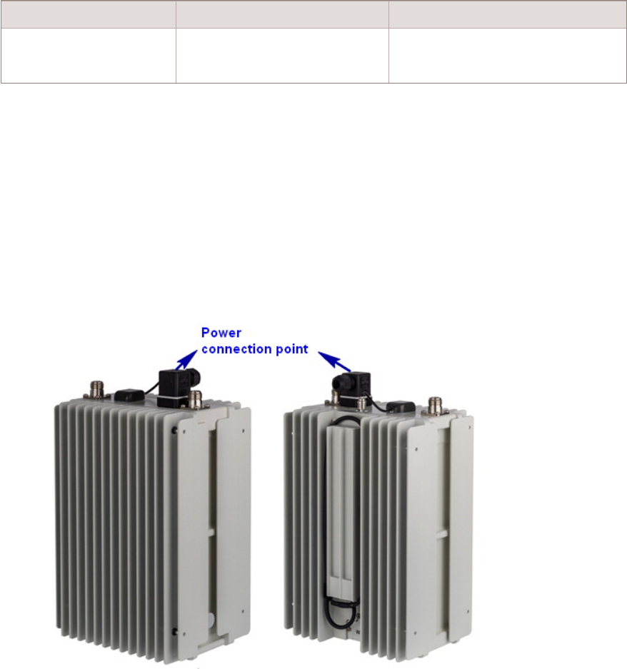
Table 5-1 Power materials (continued)
Item Description Use
Power cable (DC) Power cable pre-assembled with DC
power connector, various lengths
(2m. 4.5m, 9m, 12m)
Required for 9764 CMCO with DC power
(North America Regional markets)
Note: For Non-NAR appropriate power connector (AC or DC) needs to be selected,
NAR specific power cables are prefab cables and already assembled with power
connectors.
Power connection point
Power is supplied to the 9764 CMCO B41 2x6W located on the top side of the unit.
Figure 5-1 Power connection point
Electrical power requirements Product power requirements
....................................................................................................................................................................................................................................
....................................................................................................................................................................................................................................
9764 CMCO B41 2x6W
3MN-02026-0001-RJZZA
Issue 0.01 March 2015
Alcatel-Lucent – Proprietary
Use pursuant to applicable agreements 5-9
D
RAFT
D
RAFT
Electrical power requirements Product power requirements
....................................................................................................................................................................................................................................
....................................................................................................................................................................................................................................
5-10 Alcatel-Lucent – Proprietary
Use pursuant to applicable agreements
9764 CMCO B41 2x6W
3MN-02026-0001-RJZZA
Issue 0.01 March 2015
D
RAFT
D
RAFT

66Backhaul requirements
Overview
Purpose
This chapter provides the backhaul requirements for the Alcatel-Lucent 9764 Compact
Metro Cell Outdoor B41 2x6W.
Contents
Ethernet requirements 6-2
...................................................................................................................................................................................................................................
9764 CMCO B41 2x6W
3MN-02026-0001-RJZZA
Issue 0.01 March 2015
Alcatel-Lucent – Proprietary
Use pursuant to applicable agreements 6-1
D
RAFT
D
RAFT
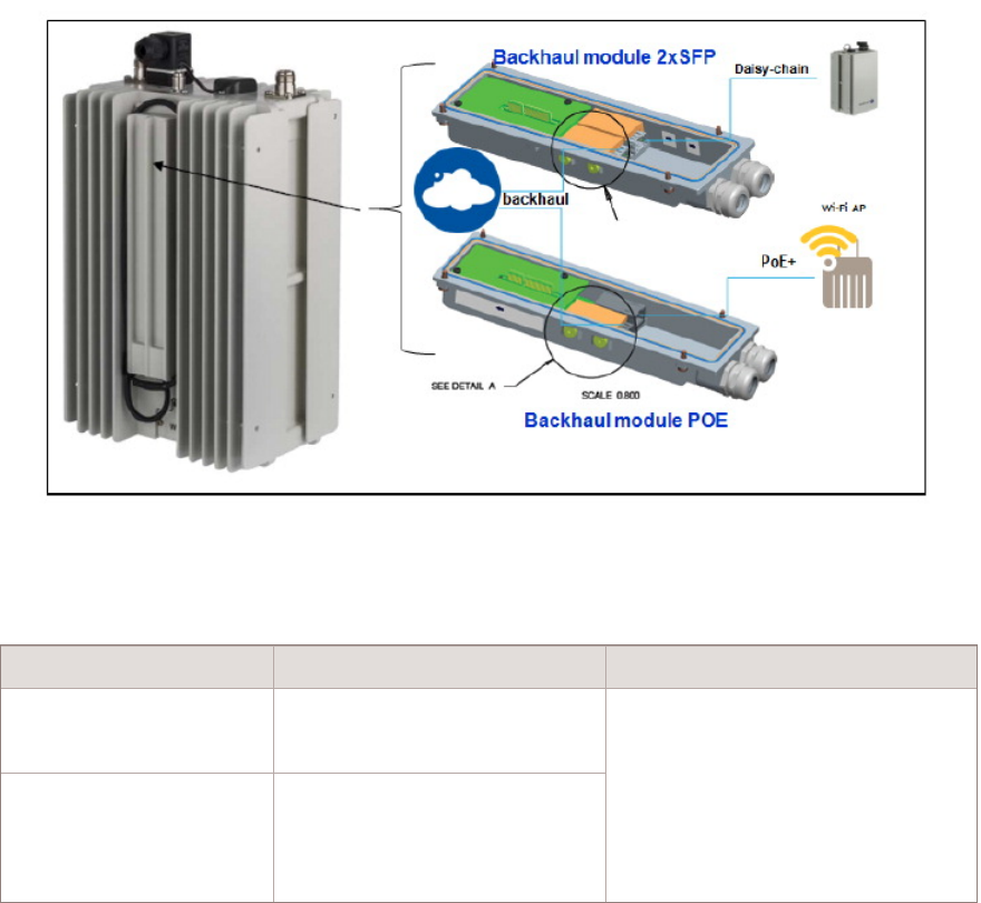
Ethernet requirements
General requirements
The Backhaul Module terminates the backhaul and Daisy chain connectivity and is
located at the rear of the 9764 CMCO B41 2x6W. The Backhaul Module is mandatory for
each 9764 CMCO B41 2x6W.
There are different versions of the Backhaul module available:
•The Backhaul Module 2 x SFP provides two SFP cages for backhaul connection and
Daisy Chain. Optical and electrical SFPs are supported.
•The Backhaul Module PoE provides one PoE+ capable RJ45 connector (for powering
an external PoE device) and one SFP cage. The SFP cage supports optical and
electrical SFPs.
Table 6-1 Backhaul Module
Item Description Use
Backhaul Module 2 x SFP Provides two SFP cages for backhaul
connection and Daisy Chain. Optical
and electrical SFPs are supported.
Mandatory
One backhaul module variant required per
9764 CMCO
Backhaul Module POE Provides one PoE+ capable RJ45
connector (for powering an external
PoE device) and one SFP cage. The
SFP cage supports optical and
electrical SFPs.
Backhaul requirements Ethernet requirements
....................................................................................................................................................................................................................................
....................................................................................................................................................................................................................................
6-2 Alcatel-Lucent – Proprietary
Use pursuant to applicable agreements
9764 CMCO B41 2x6W
3MN-02026-0001-RJZZA
Issue 0.01 March 2015
D
RAFT
D
RAFT

SFP transceivers
The 9764 CMCO provides two SFP cages. Depending on the backhaul interface provided
for connecting the 9764 CMCO the proper SFP must be inserted in the SFP cage.
Item Description Use
SFP module SFP GBE 10/100/1000BaseT
(copper)
Optional
Electrical backhaul only
SFP module SFP GBE 1000BaseLX (Single
mode)
Optional
Optical backhaul, Daisy chaining
SFP module SFP GBE 1000BaseLX / CPRI
(Single mode)
Optional
Optical backhaul, Daisy chaining
SFP module SFP GBE 1000BaseSX / CPRI (Multi
mode)
Optional
Optical backhaul, Daisy chaining
SFP module GPON SFP Optional
Optical backhaul only
Ethernet cabling options
The following tables outline the Ethernet cabling options.
Table 6-2 Ethernet cable - Electrical
Item Description Use
Electrical Ethernet cable 2m, 25m, 100m outdoor, 4 pairs, 2
RJ45 (plus 1 spare)
Optional
Use with SFP GBE 10/100/1000BaseT
(International markets)
Electrical Ethernet cable 2m, 25m, 100m outdoor, 4 pairs, 2
RJ45 (plus 1 spare)
Optional
Use with SFP GBE 10/100/1000BaseT
(North America Regional markets)
Table 6-3 Ethernet cable - Optical
Item Description Use
Fiber Optic cable SMDF LC-LC 2SM 1m, 2.5m, 5m,
10m, 15m, 30m, 50m, 70m, 85m,
100m, 150m, 200m, 250m, 300m
Optional
Single mode fiber duplex. 80mm/80mm
Breakout, Outer diameter: 5.5mm
Use for Single Mode link (select cable
length)
Fiber Optic cable MM LC-LC 2MM 1m, 2.5m, 5m,
10m, 15m, 30m, 50m, 70m, 85m,
100m, 150m, 200m, 250m, 300m
Optional
Multi Mode fiber duplex. 80mm/80mm
Breakout, Outer diameter: 5.5mm
Use for Multi Mode link (select cable
length)
Backhaul requirements Ethernet requirements
....................................................................................................................................................................................................................................
....................................................................................................................................................................................................................................
9764 CMCO B41 2x6W
3MN-02026-0001-RJZZA
Issue 0.01 March 2015
Alcatel-Lucent – Proprietary
Use pursuant to applicable agreements 6-3
D
RAFT
D
RAFT
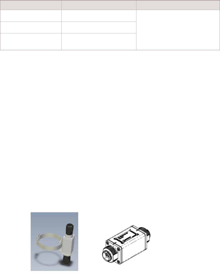
Table 6-4 Ethernet cable - Optical for GPON
Item Description Use
Fiber Optic cable SM SC-PC 1SM OFNR-LS BK75 4m Optional
Single mode fiber simlex. 75mm/75mm
Breakout
Rules: required for GPON link
Qty: (1) per GPN link. Select fiber of
length required
Fiber Optic cable SC-PC 1SM OFNR-LS BK75 8m
Fiber Optic cable SM SC-PC 1SM OFNR-LS BK75
12m
Ethernet surge protection
Where electrical backhaul is used (1000 BaseT) particularly in regions where there is a
high probability of lightning strike, it is highly recommended to use an optional Ethernet
surge arrestor as the GBE ports within the 9764 CMCO provide no surge protection for
the backhaul connection.
A external surge arrestor should be mounted close to the 9764 CMCO. Surge arrestor
characteristics:
•Data rate: Up to 1000 Mb/s
•Typical capacity: 15pF, L-G
•Operating voltage:
– +/- 48V DC (nominal)
– +/- 60V DC (max. continuous)
•Maximum surge:
– 100A, 10/1000μsec CORE-1089
– 3kA, 8/20 μsec IEC 61000-4-5
Figure 6-1 Ethernet surge arrestor
Backhaul requirements Ethernet requirements
....................................................................................................................................................................................................................................
....................................................................................................................................................................................................................................
6-4 Alcatel-Lucent – Proprietary
Use pursuant to applicable agreements
9764 CMCO B41 2x6W
3MN-02026-0001-RJZZA
Issue 0.01 March 2015
D
RAFT
D
RAFT
Conduit requirements
For outdoor installations, in countries where local regulations dictate, Ethernet cables are
required to be routed to the equipment within rigid-steel or liquid-tight flexible metal
conduit. As part of site preparation, the customer must provide the metal conduit and
associated fittings for cable routes and connecting conduit to the outdoor equipment.
Backhaul requirements Ethernet requirements
....................................................................................................................................................................................................................................
....................................................................................................................................................................................................................................
9764 CMCO B41 2x6W
3MN-02026-0001-RJZZA
Issue 0.01 March 2015
Alcatel-Lucent – Proprietary
Use pursuant to applicable agreements 6-5
D
RAFT
D
RAFT
Backhaul requirements Ethernet requirements
....................................................................................................................................................................................................................................
....................................................................................................................................................................................................................................
6-6 Alcatel-Lucent – Proprietary
Use pursuant to applicable agreements
9764 CMCO B41 2x6W
3MN-02026-0001-RJZZA
Issue 0.01 March 2015
D
RAFT
D
RAFT

77Antenna requirements
Overview
Purpose
This chapter provides an overview of the antenna interface requirements for the
Alcatel-Lucent 9764 Compact Metro Cell Outdoor B41 2x6W.
Contents
General antenna cable requirements 7-2
Antenna configuration options 7-3
...................................................................................................................................................................................................................................
9764 CMCO B41 2x6W
3MN-02026-0001-RJZZA
Issue 0.01 March 2015
Alcatel-Lucent – Proprietary
Use pursuant to applicable agreements 7-1
D
RAFT
D
RAFT
General antenna cable requirements
General requirements
The appropriate antenna type, cable length and type, and number of antenna jumper
cables should be available at the site for the start of the installation.
The following are general antenna requirements:
•The appropriate Alcatel-Lucent recommended antenna should be used.
•The appropriate Alcatel-Lucent recommended antenna cables should be used.
•All antenna cable runs must be appropriately supported in accordance with the
connector and cable manufacturer's instructions.
•Grounding of the antenna feeder cable outer shield must be performed in accordance
with the ground kit manufacturer's instructions.
•All antenna cable connectors must be at least IP67 rated (IP67 rating requirement, as
defined by IEC 60529, calls for total protection against dust and protection against
submersion in water).
•Antenna and cable sweeps must be performed prior to the start of the installation.
Note: Two different external GPS antennas are available. The 26 dB gain GPS
antenna should be used when antenna cable loss is less than 10 dB at 1575 MHz. For
antenna cable loss greater than 10 dB at 1575 MHz, the 40 dB gain antenna should be
used.
Antenna installation
Antenna installations shall be performed in accordance with all applicable manufacturer's
recommendations, and national laws and regulations.
To ensure correct antenna installation, all necessary calculations and/or field
measurements shall be evaluated for compliance with applicable national laws or
regulations regarding exposure to electromagnetic fields. The antenna manufacturer or
supplier shall deliver all technical data necessary to perform this compliance evaluation
(e.g., antenna gain pattern, antenna dimensions, etc.). Information on the methodology
and results of the compliance evaluation shall be available for inspection by officials of
the governing authorities.
Important! Do not mount the GPS antenna within 10 feet (3 m) of any transmit
antenna.
Antenna cable grounding
Grounding of the antenna cable outer shield must be performed in accordance with the
ground kit manufacturer's instructions and as outlined in Grounding and Lightning
Protection Guidelines for Wireless System Cell Sites, 401-200-115.
Antenna requirements General antenna cable requirements
....................................................................................................................................................................................................................................
....................................................................................................................................................................................................................................
7-2 Alcatel-Lucent – Proprietary
Use pursuant to applicable agreements
9764 CMCO B41 2x6W
3MN-02026-0001-RJZZA
Issue 0.01 March 2015
D
RAFT
D
RAFT
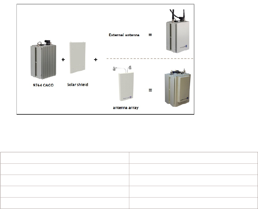
Antenna configuration options
RF antenna
Compact Metro Cell Antenna Array is designed to be mounted to the front of the 9764
CMCO. The antenna is attached to a solar shield. The Solar Shield acts as an adaptor
plate for the antenna.
The two different antenna configurations allow an adaptation of the vertical beam width.
•Single Element Antenna Module (SEM-2600): 7.5 dBi typical gain, 80° H x 75° V
HPBW
•Dual Element Antenna Module (DEM-2600): 9.5 dBi typical gain, 80° H x 35° V
HPBW
Table 7-1 Main Characteristics of Antenna Array
Dimensions H x W x D (mm) 212x114x23mm
Weight <0.6 kg
Operating ambient temperature -40°C to +85°C
Connector type 2 x Type N male, pigtail cables
Impedance 50 Ohms
Figure 7-1 9764 CMCO with antenna
Antenna requirements Antenna configuration options
....................................................................................................................................................................................................................................
....................................................................................................................................................................................................................................
9764 CMCO B41 2x6W
3MN-02026-0001-RJZZA
Issue 0.01 March 2015
Alcatel-Lucent – Proprietary
Use pursuant to applicable agreements 7-3
D
RAFT
D
RAFT
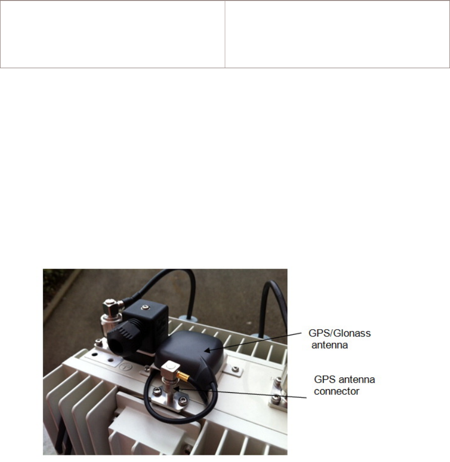
Table 7-1 Main Characteristics of Antenna Array (continued)
Gain for B41 antenna (2490 MHz – 2690
MHz)
Single Element Antenna: 7.5 dBi (typ), 7dBi
(min)
Dual Element Antenna): 9.5 dBi (typ), 9dBi
(min)
Default GPS antenna/Remote GPS antenna
The 9764 CMCO is always delivered with an external GPS/Glonass antenna attached to
the top of the housing for the following antenna configurations:
•Default GPS antenna: This attached GPS/Glonass antenna is connected via a 70cm
long cable to the QMA connector located on the top of the MCO housing.
•Remote GPS antenna: If the GPS antenna shall be located on a different position
than the 9764 CMCO, a remote located GPS antenna can be used.
Figure 7-2 Default GPS antenna configuration
Antenna requirements Antenna configuration options
....................................................................................................................................................................................................................................
....................................................................................................................................................................................................................................
7-4 Alcatel-Lucent – Proprietary
Use pursuant to applicable agreements
9764 CMCO B41 2x6W
3MN-02026-0001-RJZZA
Issue 0.01 March 2015
D
RAFT
D
RAFT
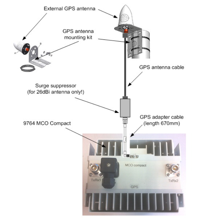
Figure 7-3 Remote GPS antenna configuration
Antenna requirements Antenna configuration options
....................................................................................................................................................................................................................................
....................................................................................................................................................................................................................................
9764 CMCO B41 2x6W
3MN-02026-0001-RJZZA
Issue 0.01 March 2015
Alcatel-Lucent – Proprietary
Use pursuant to applicable agreements 7-5
D
RAFT
D
RAFT
Antenna requirements Antenna configuration options
....................................................................................................................................................................................................................................
....................................................................................................................................................................................................................................
7-6 Alcatel-Lucent – Proprietary
Use pursuant to applicable agreements
9764 CMCO B41 2x6W
3MN-02026-0001-RJZZA
Issue 0.01 March 2015
D
RAFT
D
RAFT

Appendix A: Site survey
checklists
Overview
Purpose
In the following checklists, venue refers to the general area, such as a stadium, enterprise
campus, or airport terminal, at which the equipment will be located, and specific site
refers to the exact position at which the equipment will be installed in that venue.
Contents
SS-1 Venue survey checklist A-2
SS-2 Site survey general checklist A-4
SS-3 Site survey access checklist A-7
SS-4 Site survey conclusion A-9
...................................................................................................................................................................................................................................
9764 CMCO B41 2x6W
3MN-02026-0001-RJZZA
Issue 0.01 March 2015
Alcatel-Lucent – Proprietary
Use pursuant to applicable agreements A-1
D
RAFT
D
RAFT

SS-1 Venue survey checklist
Venue address
Venue
Name
Street address
City, State
Venue details
The following items must be completed prior to the installation of site equipment. Circle
the correct letter for the corresponding item descriptions.
Item
#
Description Yes
(Y)
No
(N)
N/A Comments
1. The altitude of the venue relative to sea
level is between −197 ft and +5900 ft.
Y N N/A
2. Ambient temperatures at the venue are
expected to remain above −40 °F (-40 °C)
and below 131°F (55 °C).
Y N N/A
3. Temperature swings at the venue are
expected to be always less than 86 °F (30
°C).
Y N N/A
4. Humidity at the venue is expected to be
always 5% or greater.
Y N N/A
5. RF spectrum analysis has been performed
in the venue at various times of day on
various days of the week and has shown
no activity that is likely to cause
interference with the transmission or
reception of the Metro Cells.
Y N N/A
6. The power factor of 0.92 meets the
approval of the company that supplies
power to the venue.
Y N N/A
7. Dust at the venue is expected to be below
the limit for a NEMA Type 4 enclosure.
Y N N/A
Site survey checklists SS-1 Venue survey checklist
....................................................................................................................................................................................................................................
....................................................................................................................................................................................................................................
A-2 Alcatel-Lucent – Proprietary
Use pursuant to applicable agreements
9764 CMCO B41 2x6W
3MN-02026-0001-RJZZA
Issue 0.01 March 2015
D
RAFT
D
RAFT

Item
#
Description Yes
(Y)
No
(N)
N/A Comments
8. Corrosive salt fog at the venue is
expected to be below the limit for a
NEMA Type 4 enclosure.
Y N N/A
Notes:
1. Completed by: ______________________
2. Date: _______
Site survey checklists SS-1 Venue survey checklist
....................................................................................................................................................................................................................................
....................................................................................................................................................................................................................................
9764 CMCO B41 2x6W
3MN-02026-0001-RJZZA
Issue 0.01 March 2015
Alcatel-Lucent – Proprietary
Use pursuant to applicable agreements A-3
D
RAFT
D
RAFT

SS-2 Site survey general checklist
Name, address and location
Specific site
Site name:
Site code:
GPS Location:
Latitude:
Longitude:
Altitude:
Elevation:
Accuracy:
Type of site
The following items must be completed prior to the installation of site equipment. Circle
the correct letter for the corresponding item descriptions.
Item # Type of site Yes
(Y)
No
(N)
N/A Height
1. Indoor / stadium Y N N/A
2. Outdoor pole Y N N/A
3. Outdoor building façade Y N N/A
4.` Outdoor short post Y N N/A
Notes:
1. Completed by: ______________________
2. Date: _______
Site environment
The following items must be completed prior to the installation of site equipment. Circle
the correct letter for the corresponding item descriptions.
Site survey checklists SS-2 Site survey general checklist
....................................................................................................................................................................................................................................
....................................................................................................................................................................................................................................
A-4 Alcatel-Lucent – Proprietary
Use pursuant to applicable agreements
9764 CMCO B41 2x6W
3MN-02026-0001-RJZZA
Issue 0.01 March 2015
D
RAFT
D
RAFT

Item # Site environment Yes
(Y)
No
(N)
N/A Comments
1. Wind-driven rain at the specific
site is expected to be beneath the
limit for a NEMAType 4
enclosure.
Y N N/A
2. The minimum distance between
the installed equipment and the
general public conforms with
that specified in the“ Product
safety and RF exposure” section
of the Product Conformance
Appendix
Y N N/A
3. The mounting location is large
enough to accommodate the
Metro Cell with its mounting
bracket(s).
Y N N/A
Notes:
1. Completed by: ______________________
2. Date: _______
Existing equipment type
The following items must be completed prior to the installation of site equipment. Circle
the correct letter for the corresponding item descriptions.
Item # Equipment type Yes
(Y)
No
(N)
N/A Comments
1. Metro Cell Y N N/A
2. 7705 SAR-W Y N N/A
3. Other Y N N/A
Notes:
1. Completed by: ______________________
2. Date: _______
Site survey checklists SS-2 Site survey general checklist
....................................................................................................................................................................................................................................
....................................................................................................................................................................................................................................
9764 CMCO B41 2x6W
3MN-02026-0001-RJZZA
Issue 0.01 March 2015
Alcatel-Lucent – Proprietary
Use pursuant to applicable agreements A-5
D
RAFT
D
RAFT

Existing power type
The following items must be completed prior to the installation of site equipment. Circle
the correct letter for the corresponding item descriptions.
Item # Power Yes
(Y)
No
(N)
N/A Comments
1. AC Y N N/A
1(a). AC power voltage is:
110 V or 220 V nominal
Y N N/A
1(b). AC power frequency range:
from 47 Hz to 63 Hz
Y N N/A
2. DC Y N N/A
2(a). DC power voltage is:
-48 VDC
Y N N/A
3. Battery Y N N/A
Notes:
1. Completed by: ______________________
2. Date: _______
Existing transmission type
The following items must be completed prior to the installation of site equipment. Circle
the correct letter for the corresponding item descriptions.
Item # Transmission type Yes
(Y)
No
(N)
N/A Comments
1. IP/MPLS Y N N/A
2. xDSL Y N N/A
3. GPON Y N N/A
4. WiFi Y N N/A
5. Wireless (MPR, etc.) Y N N/A
Notes:
1. Completed by: ______________________
2. Date: _______
Site survey checklists SS-2 Site survey general checklist
....................................................................................................................................................................................................................................
....................................................................................................................................................................................................................................
A-6 Alcatel-Lucent – Proprietary
Use pursuant to applicable agreements
9764 CMCO B41 2x6W
3MN-02026-0001-RJZZA
Issue 0.01 March 2015
D
RAFT
D
RAFT

SS-3 Site survey access checklist
Persons to contact
Responsible for site Name:
Phone:
Fax:
Email:
Necessary Authorization Name:
Phone:
Fax:
Email:
Subcontractor Name:
Phone:
Fax:
Email:
Other persons Name:
Phone:
Fax:
Email:
Notes:
1. Completed by: ______________________
2. Date: _______
Lock and key information
Any
locked
boxes
Y N N/A Key
provided
by
Name:
Phone:
Fax:
Email:
Notes:
1. Completed by: ______________________
2. Date: _______
Site survey checklists SS-3 Site survey access checklist
....................................................................................................................................................................................................................................
....................................................................................................................................................................................................................................
9764 CMCO B41 2x6W
3MN-02026-0001-RJZZA
Issue 0.01 March 2015
Alcatel-Lucent – Proprietary
Use pursuant to applicable agreements A-7
D
RAFT
D
RAFT

Site location access
Ladder
required
Y N N/A Height of ladder
Crane
required
Y N N/A Height of crane
Parking
available
Y N N/A Distance to site
Bucket truck
required
Y N N/A Height
Notes:
1. Completed by: ______________________
2. Date: _______
Site survey checklists SS-3 Site survey access checklist
....................................................................................................................................................................................................................................
....................................................................................................................................................................................................................................
A-8 Alcatel-Lucent – Proprietary
Use pursuant to applicable agreements
9764 CMCO B41 2x6W
3MN-02026-0001-RJZZA
Issue 0.01 March 2015
D
RAFT
D
RAFT

SS-4 Site survey conclusion
Site acceptance
OK
OK, action required
NOK
Action items
Severity Description
Blocking Major Minor
1
2
3
4
Resolution
Date Representative Representative Description
Name Initials Name Initials
1
2
3
4
Survey approval
Date of site survey:
Name Signature
Site survey checklists SS-4 Site survey conclusion
....................................................................................................................................................................................................................................
....................................................................................................................................................................................................................................
9764 CMCO B41 2x6W
3MN-02026-0001-RJZZA
Issue 0.01 March 2015
Alcatel-Lucent – Proprietary
Use pursuant to applicable agreements A-9
D
RAFT
D
RAFT
Site survey checklists SS-4 Site survey conclusion
....................................................................................................................................................................................................................................
....................................................................................................................................................................................................................................
A-10 Alcatel-Lucent – Proprietary
Use pursuant to applicable agreements
9764 CMCO B41 2x6W
3MN-02026-0001-RJZZA
Issue 0.01 March 2015
D
RAFT
D
RAFT

Appendix B: Site preparation
checklists
Overview
Purpose
This section is for use by authorized personnel to verify completion of cell site
preparation activities prior to installation of Metro Cell equipment.
SP-GEN cell site general information
Complete the following information about the cell site.
•Cell Site Name: ______________________
•Cell Site Address: ______________________
•Cell Site Access Contact Name: ______________________
•Market Name: ______________________
•Cell Site number: ______________________
•Contact Phone number: ______________________.
Contents
SP-1 Site preparation general checklist B-2
SP-2 Site preparation power source checklist B-3
SP-3 Site preparation grounding checklist B-4
SP-4 Site preparation RF antenna checklist B-6
SP-5 Site preparation GPS antenna checklist B-7
Site preparation punch list sheet B-9
Site preparation punchlist sheet B-10
...................................................................................................................................................................................................................................
9764 CMCO B41 2x6W
3MN-02026-0001-RJZZA
Issue 0.01 March 2015
Alcatel-Lucent – Proprietary
Use pursuant to applicable agreements B-1
D
RAFT
D
RAFT

SP-1 Site preparation general checklist
Purpose
Where applicable, the following items must be completed prior to the installation of site
equipment. Circle the correct letter for the corresponding item descriptions.
Item
#
Description Yes
(Y)
No
(N)
N/A Comments
1. Are site environmental conditions within
equipment specified operating range?
Y N N/A
2. Has the required space been provided
around equipment [i.e., maintenance
access, heat dissipation, safety]?
Y N N/A
3. Has a Method of Procedure (MOP) been
developed with the installation
supervisor?
Y N N/A
4. Has installer site equipment parameter
sheet been completed and reviewed with
the installation supervisor?
Y N N/A
5. Has all equipment been ordered and has
delivery to site been scheduled?
Y N N/A
6. Have all necessary arrangements been
made for access to the site?
Y N N/A
7. Have all necessary arrangements been
made to get equipment onto the site
(crane, etc.)?
Y N N/A
Notes:
1. Completed by: ______________________
2. Date: _______
Site preparation checklists SP-1 Site preparation general checklist
....................................................................................................................................................................................................................................
....................................................................................................................................................................................................................................
B-2 Alcatel-Lucent – Proprietary
Use pursuant to applicable agreements
9764 CMCO B41 2x6W
3MN-02026-0001-RJZZA
Issue 0.01 March 2015
D
RAFT
D
RAFT

SP-2 Site preparation power source checklist
Purpose
Where applicable, the following items must be completed prior to the installation of the
site equipment. Circle the correct letter for the corresponding item descriptions.
Item
#
Description Yes
(Y)
No
(N)
N/A Comments
1. Is power service available? Y N N/A
2. Have power service and conduits been
approved by local code?
Y N N/A
3. Is power service equipped with surge
protection at service entry point?
Y N N/A
4. Is the power source appropriate for
equipment being installed?
Y N N/A
5. Does power service have proper circuit
breaker rating(s) and labeling?
Y N N/A
6. Is power circuit breaker(s) available and
labeled for power system?
Y N N/A
7. Is power circuit breaker(s) available and
labeled for listed ancillary equipment?
Y N N/A
A. Y N N/A
B. Y N N/A
C. Y N N/A
8. Do elevated lighting, intrusion lighting,
etc. feeds have proper lightning
protection?
Y N N/A
9. If not supplied with the product, have at
least two AC duplex convenience outlets
been provided within 1.5 meters (5 feet)
of the product?
NOTE: A Ground Fault Circuit Interrupt
(GFCI) type is recommended, and must
be used when required by code.
Y N N/A
10. Is each outlet protected by a UL/CSA
listed, or approved 15 A circuit breaker?
Y N N/A
Site preparation checklists SP-2 Site preparation power source checklist
....................................................................................................................................................................................................................................
....................................................................................................................................................................................................................................
9764 CMCO B41 2x6W
3MN-02026-0001-RJZZA
Issue 0.01 March 2015
Alcatel-Lucent – Proprietary
Use pursuant to applicable agreements B-3
D
RAFT
D
RAFT

SP-3 Site preparation grounding checklist
Purpose
Where applicable, the following items must be completed prior to the installation of the
site equipment. Circle the correct letter for the corresponding description items.
Item
#
Description Yes
(Y)
No
(N)
N/A Comments
1. Is soil resistivity and site resistance test
on file?
Y N N/A
2. Has connection been provided to
grounding electrode system?
If yes, circle all that apply:
A. Via a buried ring ground and driven
rod(s)
B. Via a buried metallic and electrically
continuous water pipe
C. Via driven ground rod(s) and/or
plate(s)
D. Via electrolytic ground rod(s)
E. Via grounded building steel
F. Via grounded grid or radial
Y N N/A
3. Is antenna support structure(s) grounded? Y N N/A
4. Is antenna tower bonded to grounding
electrode system?
Y N N/A
5. Are any guy wires bonded to grounding
electrode system?
Y N N/A
6. Are antenna cable shields grounded at
both ends?
Y N N/A
7. Are all ground connections in compliance
with Alcatel-Lucent requirements
(exothermic weld, compression type with
2-hole lugs; properly secured;
anti-oxidant used on contact surface
area)?
Y N N/A
8. Are all grounding conductors routed as
straight as possible with no loops or sharp
bends?
Y N N/A
9. Is equipment support structure grounded? Y N N/A
Site preparation checklists SP-3 Site preparation grounding checklist
....................................................................................................................................................................................................................................
....................................................................................................................................................................................................................................
B-4 Alcatel-Lucent – Proprietary
Use pursuant to applicable agreements
9764 CMCO B41 2x6W
3MN-02026-0001-RJZZA
Issue 0.01 March 2015
D
RAFT
D
RAFT

Item
#
Description Yes
(Y)
No
(N)
N/A Comments
10. Are metallic conduits bonded at both ends
and 7.62-meters (25-foot) intervals?
Y N N/A
11. Is power supply equipped with a surge
protection device and is the device
properly connected to the ground system?
Y N N/A
12. Are the additional surge protection
devices properly connected to the ground
system?
Y N N/A
13. Is strand cable adequately grounded? Y N N/A
Notes:
1. Completed by: ______________________
2. Date: _______
Site preparation checklists SP-3 Site preparation grounding checklist
....................................................................................................................................................................................................................................
....................................................................................................................................................................................................................................
9764 CMCO B41 2x6W
3MN-02026-0001-RJZZA
Issue 0.01 March 2015
Alcatel-Lucent – Proprietary
Use pursuant to applicable agreements B-5
D
RAFT
D
RAFT

SP-4 Site preparation RF antenna checklist
Purpose
Where applicable, the following items must be completed prior to the installation of the
RF cell site equipment. Circle the correct letter for the corresponding item descriptions.
Item
#
Description Yes
(Y)
No
(N)
N/A Comments
1. Are all antenna cable runs installed? Y N N/A
2. Are all antenna cable runs properly
terminated with the appropriate
connectors on the equipment side?
Y N N/A
3. Are all cable connections torqued to the
appropriate value?
Y N N/A
4. If required, are the optional RF antenna
cables equipped with surge protection
devices?
Y N N/A
5. Are all external cables UV rated? Y N N/A
6. Are antenna cable runs' demarcation
points in proper location?
Y N N/A
7. Are antenna cable runs marked and in
proper sequence per applicable equipment
drawings?
Y N N/A
8. Are appropriate type, length and number
of antenna cable jumpers available?
Y N N/A
9. Are appropriate drip loops provided for
antenna cable runs at turns and
demarcation point?
Y N N/A
10. Have antenna and cable sweeps been
performed?
Y N N/A
11. Are antennas properly installed and
secured?
Y N N/A
Notes:
1. Completed by: ______________________
2. Date: _______
Site preparation checklists SP-4 Site preparation RF antenna checklist
....................................................................................................................................................................................................................................
....................................................................................................................................................................................................................................
B-6 Alcatel-Lucent – Proprietary
Use pursuant to applicable agreements
9764 CMCO B41 2x6W
3MN-02026-0001-RJZZA
Issue 0.01 March 2015
D
RAFT
D
RAFT

SP-5 Site preparation GPS antenna checklist
Purpose
Where applicable, the following items must be completed prior to the installation of the
site equipment. Circle the correct letter for the corresponding item descriptions.
Item
#
Description Yes
(Y)
No
(N)
N/A Comments
1. Is antenna installed with base level within
two degrees?
Y N N/A
2. Is antenna installed with less than 25% of
the sky masked by obstruction?
Y N N/A
3. Is GPS antenna located at least 3.05 m
(10 ft.) vertically and horizontally from
any active transmit antenna?
Y N N/A
4. Are aggregate cable loss, cable VSWR,
total cable length, cable type, GPS
antenna gain, KS list and serial numbers
recorded in the site installation records?
Y N N/A
5. Is proper gain antenna installed for the
total aggregate cable loss and length?
Y N N/A
6. Is measured cable VSWR within its
specified value?
Y N N/A
7. If required, is the GPS antenna cable
properly grounded and equipped with a
proper surge protection device?
Y N N/A
8. Are proper service loops provided near
antenna?
Y N N/A
9. Is proper drip loop provided for the
outdoor antenna jumper cables?
Y N N/A
10. Are cable connections torqued to the
appropriate value?
Y N N/A
12. Are all external cables UV rated? Y N N/A
13. Are antenna bracket, pipes, and antenna
properly secured?
Y N N/A
14. If required, has weatherproof protection
tape been applied to GPS antenna cable
connector joints?
Y N N/A
Site preparation checklists SP-5 Site preparation GPS antenna checklist
....................................................................................................................................................................................................................................
....................................................................................................................................................................................................................................
9764 CMCO B41 2x6W
3MN-02026-0001-RJZZA
Issue 0.01 March 2015
Alcatel-Lucent – Proprietary
Use pursuant to applicable agreements B-7
D
RAFT
D
RAFT

Item
#
Description Yes
(Y)
No
(N)
N/A Comments
15. Was GPS antenna location verified for
line of sight using a GPS test unit or
equivalent?
Y N N/A
16. Is GPS antenna location free of external
interference (i.e., radio stations,
collocated equipment, etc.)?
Y N N/A
Notes:
1. Completed by: ______________________
2. Date: _______
Site preparation checklists SP-5 Site preparation GPS antenna checklist
....................................................................................................................................................................................................................................
....................................................................................................................................................................................................................................
B-8 Alcatel-Lucent – Proprietary
Use pursuant to applicable agreements
9764 CMCO B41 2x6W
3MN-02026-0001-RJZZA
Issue 0.01 March 2015
D
RAFT
D
RAFT

Site preparation punch list sheet
Purpose
The following punch list is used to track any outstanding site preparation items.
Item # Comment/Description Severity (1/2/3) Corrective Action Required
(Y/N) Completed Date
Notes:
1. Equipment installation cannot occur until outage is rectified and will void warranty or potentially cause
personal injury.
2. Equipment installation can occur but issue must be rectified prior to handoff to customer or service turn-up
so that the warranty is not voided.
3. Equipment installation, handoff to customer, or service turn-up can occur but not per Alcatel-Lucent
recommendations.
4. Inspection Checklist Completion Sign-Off (complete below)
5. Was the punchlist continuation sheet on the next page used? Yes or No
6. Inspector's Name: ______________________
7. Inspector's Signature: _____________________ Date: _________
Site preparation checklists Site preparation punch list sheet
....................................................................................................................................................................................................................................
....................................................................................................................................................................................................................................
9764 CMCO B41 2x6W
3MN-02026-0001-RJZZA
Issue 0.01 March 2015
Alcatel-Lucent – Proprietary
Use pursuant to applicable agreements B-9
D
RAFT
D
RAFT

Site preparation punchlist sheet
Purpose
The following punchlist is used to track any outstanding site preparation items.
Item # Comment/Description Severity
(1/2/3)
Corrective Action
Required
(Y/N) Completed
Date
Site preparation checklists Site preparation punchlist sheet
....................................................................................................................................................................................................................................
....................................................................................................................................................................................................................................
B-10 Alcatel-Lucent – Proprietary
Use pursuant to applicable agreements
9764 CMCO B41 2x6W
3MN-02026-0001-RJZZA
Issue 0.01 March 2015
D
RAFT
D
RAFT

Appendix C: Product
conformance statements
Overview
Purpose
This section presents the product conformance statements that apply to the Alcatel-Lucent
Metro Cell Outdoor Access Point equipment when deployed in the United States.
The statements that are required are determined primarily by national or multi-national
regulations. However, in some regions, contract terms determine which statements are
required.
The presence of the statement indicates that the product does comply with that statement
wherever it is required to do so.
Contents
Federal Communications Commission C-2
Product safety conformance statements C-4
Antenna exposure statements C-5
FDA/IEC optical transmitter product compliance statements C-7
Eco-environmental statements C-8
...................................................................................................................................................................................................................................
9764 CMCO B41 2x6W
3MN-02026-0001-RJZZA
Issue 0.01 March 2015
Alcatel-Lucent – Proprietary
Use pursuant to applicable agreements C-1
D
RAFT
D
RAFT

Federal Communications Commission
Federal Communications Commission
Important! Changes or modifications not expressly approved by Alcatel-Lucent, Inc.
could void the user’s authority to operate the equipment.
This device complies with Part 15 of the FCC Rules. Operation is subject to the following
two conditions:
(1) this device may not cause harmful interference, and
(2) this device must accept any interference received, including interference that may
cause undesired operation.
FCC Part 15 Class B
Note: This equipment has been tested and found to comply with the limits for a Class
B digital device, pursuant to Part 15 of the FCC Rules.
These limits are designed to provide reasonable protection against harmful
interference in a residential installation.
This equipment generates, uses, and can radiate radio frequency energy and, if not
installed and used in accordance with the instructions, may cause harmful interference
to radio communications. However, there is no guarantee that interference will not
occur in a particular installation.
If this equipment does cause harmful interference to radio or television reception,
which can be determined by turning the equipment off and on, the user is encouraged
to try to correct the interference by one or more of the following measures:
•Reorient or relocate the receiving antenna
•Increase the separation between the equipment and receiver
•Connect the equipment into an outlet on a circuit different from that to which the
receiver is connected
•Consult the dealer or an experienced radio/TV technician for help.
FCC Part 68
This equipment complies with Part 68 of the FCC rules and the requirements adopted by
the ACTA. At the upper-right-hand corner inside the cabinet assembly of this equipment
is a label that contains, among other information, a product identifier in the format of
AAAEQ##TXXXX. If requested, this number must be provided to the telephone
company.
FIC 04DU9-1SN.
Product conformance statements Federal Communications Commission
....................................................................................................................................................................................................................................
....................................................................................................................................................................................................................................
C-2 Alcatel-Lucent – Proprietary
Use pursuant to applicable agreements
9764 CMCO B41 2x6W
3MN-02026-0001-RJZZA
Issue 0.01 March 2015
D
RAFT
D
RAFT

SOC 6.0N
The T1 network interface on this equipment is hardwired to a punchdown block, which
meets the FCC specifications.
If this equipment causes harm to the telephone network, the telephone company will
notify you in advance that temporary discontinuance of service may be required.
However, if advance notice is not practical, the telephone company will notify the
customer as soon as possible. Also, you will be advised of your right to file a complaint
with the FCC if you believe it is necessary.
The telephone company may make changes in its facilities, equipment, operations, or
procedures that could affect the operation of the equipment. If this happens, the telephone
company will provide advance notice in order for you to make necessary modifications to
maintain uninterrupted service.
FCC regulations prohibit the connection of customer-provided equipment to central office
implemented systems. Connection to party lines is subject to tariffs; users should contact
their state public utility commission, public service commission, or corporation
commission for information.
If the equipment is causing harm to the telephone network, the telephone company may
request that you disconnect the equipment until the problem is resolved.
If trouble is experienced with this equipment repair or warranty information may be
obtained by contacting:
Technical Support Services, within the United States: +1 630 224 4762, prompt 2
RF approval
This equipment complies with Part 2, Subpart J - Equipment Authorization Procedures, of
the FCC Rules.
This device complies with Part 22 – Public Mobile Services, Subpart H – Cellular
Radiotelephone Services.
This equipment complies with Part 24 - Personal Communications Services, Subpart E -
Broadband PCS.
Product conformance statements Federal Communications Commission
....................................................................................................................................................................................................................................
....................................................................................................................................................................................................................................
9764 CMCO B41 2x6W
3MN-02026-0001-RJZZA
Issue 0.01 March 2015
Alcatel-Lucent – Proprietary
Use pursuant to applicable agreements C-3
D
RAFT
D
RAFT
Product safety conformance statements
Product safety conformance
The Alcatel-Lucent 9764 Compact Metro Cell Outdoor B41 2x6W is Safety Certified ITE
by CSA International.
This Certification is marked on the equipment main nameplate label. Should the local
Authority Having Jurisdiction (AHJ) require prior or additional verification of this
Certification, a Product Certificate of Compliance can be obtained from the specific
Certification Body by the Business/Product Unit Applicant for the product or by
contacting:
Technical Support Services, within the United States: +1 630 224 4762, prompt 2
Any modifications to this equipment are not permitted without review and official written
authorization from the specific Certification Body. Unauthorized changes may violate the
Product Safety Certification. Modifications or changes authorized by official CN/CNN
are assumed to have received prior approval from this Lab.
Indoor applications
This equipment is intended for installation in restricted access locations where access is
controlled or where access can only be gained by service personnel with a key or tool.
Access to this equipment is restricted to qualified service personnel only.
Product conformance statements Product safety conformance statements
....................................................................................................................................................................................................................................
....................................................................................................................................................................................................................................
C-4 Alcatel-Lucent – Proprietary
Use pursuant to applicable agreements
9764 CMCO B41 2x6W
3MN-02026-0001-RJZZA
Issue 0.01 March 2015
D
RAFT
D
RAFT
Antenna exposure statements
Antenna exposure
Antenna installations for this equipment shall be performed in accordance with all
applicable manufacturer's recommendations, and national laws and regulations. To ensure
correct antenna installation, the antenna installer shall perform all necessary calculations
and/or field measurements to evaluate compliance with applicable national laws or
regulations regarding exposure to electromagnetic fields. The supplier of radio
equipment, the supplier of antenna equipment and the integrator and builder of the site
must provide sufficient information so that the limits of the exclusion zones can be
determined. Any changes to the antenna or other equipment in the transmit path may
require re-evaluation of the exposures to electromagnetic fields.
Pursuant to 47 CFR Part 1, Subpart I, subject to the provisions of section 1.1307, all
installations must be evaluated for requirements contained in Table 1, “Limits for
maximum permissible exposure,” in section 1.1310.
Guidelines for antenna placements
1. Antennas should be placed more than 20 cm (8 inches) away from possible human RF
exposure.
2. When placing the antennas, please be aware of FCC 47 CFR 1.1307 - 1.1310 and
FCC guidelines for public safety, for example, OET Bulletin No. 56, “Questions and
Answers About the Biological Effects and Potential Hazards of Radio frequency
Electromagnetic Fields” and OET Bulletin 65, “Evaluating Compliance With FCC
Guidelines for Human Exposure to Radiofrequency Electromagnetic Fields”). FCC
requirements mandate maximum power density at location of possible exposure to be
below 0.5 mW/cm2(5 W/m2) at 750 MHz and 1 mW/cm2(10 W/m2) at AWS for
general population/uncontrolled exposure and 2.5 mW/cm2(25 W/m2) at 750 MHz
and 5 mW/cm2(50 W/m2) at AWS for occupational/controlled exposure. Exposure is
averaged over a 30 minute time period for general population and over a 6 minute
time period for occupational/controlled exposure.
Example of a B13 MCO running at 5 W (7 dBW), connected viaa2dBcable loss and
a 3 dBi antenna:
Power density at distance R from antenna is PwD = EIRP(dBW) - 10*log10(4pi*R2)
At 1 m away from the antenna, PwD(1m) = EIRP(7dBw - 2dB + 3dBi) - 11dB =
-3dBw/m2(0.5W/m2)
At 1 ft away from the antenna, PwD(0.305m) = EIRP(8dBW)-0.82dB = 7.18dBW/m2
(5.2W/m2)
Note: Losses of all components between the MCO port and antenna should be
included in EIRP calculations. MCO power in indoor applications may have to be
lowered based on antenna distance to human exposure and total EIRP.
Product conformance statements Antenna exposure statements
....................................................................................................................................................................................................................................
....................................................................................................................................................................................................................................
9764 CMCO B41 2x6W
3MN-02026-0001-RJZZA
Issue 0.01 March 2015
Alcatel-Lucent – Proprietary
Use pursuant to applicable agreements C-5
D
RAFT
D
RAFT
This example indicates that in this particular deployment configuration, US safety limits
for general population are met at a distance slightly over 1 foot for B13 operation.
Product conformance statements Antenna exposure statements
....................................................................................................................................................................................................................................
....................................................................................................................................................................................................................................
C-6 Alcatel-Lucent – Proprietary
Use pursuant to applicable agreements
9764 CMCO B41 2x6W
3MN-02026-0001-RJZZA
Issue 0.01 March 2015
D
RAFT
D
RAFT

FDA/IEC optical transmitter product compliance statements
FDA/IEC optical transmitter product compliance
Alcatel-Lucent declares that this equipment complies with the Food and Drug
Administration’s Center for Devices and Radiological Health (FDA/CDRH) regulations
21 CFR 1040.10 and 1040.11. It is a Class I/1 laser optical fiber communication systems
“product” under the FDA.
This Product is designed to ensure that personnel operating the product are not
endangered by laser radiation during normal operation and fault conditions. This product
does not present a risk of eye injury because it is fully enclosed and does not contain
embedded lasers greater than Class I/1 unless otherwise noted.
Laser warning
WARNING
Laser hazard
The light from laser and high-radiance LED's may cause eye damage if absorbed by the
retina.
•Use of controls or adjustments or performance of procedures other than those
specified herein may result in hazardous laser radiation exposure.
•Do not view directly into the laser beam with optical instruments such as a fiber
microscope because viewing of laser emission in excess of Class 1 limits significantly
increases the risk of eye damage.
•Never look into the end of an exposed fiber or an open connector as long as the
optical source is switched on.
•Ensure that the optical source is switched off before disconnecting optical fiber
connectors.
Product conformance statements FDA/IEC optical transmitter product compliance statements
....................................................................................................................................................................................................................................
....................................................................................................................................................................................................................................
9764 CMCO B41 2x6W
3MN-02026-0001-RJZZA
Issue 0.01 March 2015
Alcatel-Lucent – Proprietary
Use pursuant to applicable agreements C-7
D
RAFT
D
RAFT
Eco-environmental statements
Packaging collection and recovery requirements
Countries, states, localities, or other jurisdictions may require that systems be established
for the return and/or collection of packaging waste from the consumer, or other end user,
or from the waste stream. Additionally, reuse, recovery, and/or recycling targets for the
return and/or collection of the packaging waste may be established.
For more information regarding collection and recovery of packaging and packaging
waste within specific jurisdictions, contact the Alcatel-Lucent Environment, Health and
Safety organization or Alcatel-Lucent Hazardous Waste Center technical support at (888)
539-2783.
For installations not performed by Alcatel-Lucent, please contact the Alcatel-Lucent
Customer Support Center at:
Technical Support Services, within the United States: +1 630 224 4762, prompt 2
Material content compliance
The following notification applies to Alcatel-Lucent products distributed for sale, resale,
or use.
This product, part, or both may include a lithium-manganese dioxide battery, which
contains very small amounts of a perchlorate substance. Special handling may apply.
For California:
Perchlorate Material - special handling may apply.
See http:\\www.dtsc.ca.gov/hazardouswaste/perchlorate/.
Product conformance statements Eco-environmental statements
....................................................................................................................................................................................................................................
....................................................................................................................................................................................................................................
C-8 Alcatel-Lucent – Proprietary
Use pursuant to applicable agreements
9764 CMCO B41 2x6W
3MN-02026-0001-RJZZA
Issue 0.01 March 2015
D
RAFT
D
RAFT
Glossary
...................................................................................................................................................................................................................................
Numerics
3GPP
3rd Generation Partnership Project
...................................................................................................................................................................................................................................
A A (Ampere)
Base SI unit of electrical current.
AC (Alternating Current)
Continuously variable current, rising to a maximum in one direction, falling to zero, then
reversing direction and repeating the cycle in the other direction.
AC convenience outlet
Sites must be equipped with at least two duplex outlets for installation and maintenance
procedures. The outlets are required to power test equipment and installation tools.
Ambient temperature
The temperature of air or other media in a designated area, particularly the area
ANSI (American National Standards Institute)
An organization chartered to accredit standards developed by a wide variety of industry groups,
without influence from any one company or organization. Does not develop standards, but
reviews and implements those developed by other organizations. ANSI is a member of the
International Standards Organization (ISO).
Antenna
An elevated device for radiating or receiving radio waves. It changes electrical currents into
electromagnetic waves, and vice versa.
AP
Access Point
AWG (American Wire Gauge)
American standard for classifying wire diameter.
...................................................................................................................................................................................................................................
B Backup
Facility used to replace an element which has failed.
....................................................................................................................................................................................................................................
9764 CMCO B41 2x6W
3MN-02026-0001-RJZZA
Issue 0.01 March 2015
Alcatel-Lucent – Proprietary
Use pursuant to applicable agreements GL-1
D
RAFT
D
RAFT
Base station
The equipment that provides the air interface that allows mobile terminals to communicate with
the telecommunications network.
BBU
BaseBand Unit
BOCA
Building Officials and Code Administrators
Bonding
Permanent connection of metallic parts to form an electrically conductive path that will assure
electrical continuity and have the capability to safely conduct any current likely to be imposed.
Branch circuit
The circuit conductors between the final overcurrent device protecting the circuit and the
outlet(s).
Breaker, circuit
A cut-out device which breaks a circuit when preset limits of current are exceeded.
Buried ring ground
A buried, bare, tinned, solid copper cable encircling the site building and/or tower foundation.
...................................................................................................................................................................................................................................
C CDRH
Center for Devices and Radiological Health
Cell site
An installation located within a cell that houses the equipment needed to set up and complete calls
on a cellular telephone.
CIC ((Customer Information Center))
Source for locating and obtaining delivery of Alcatel-Lucent customer documents.
Circuit
1. The complete path between two terminals over which one-way or two-way communications
may be provided. 2. An electronic path between two or more points, capable of providing a
number of channels. 3. A number of conductors connected together for the purpose of carrying an
electrical current. 4. An electronic closed-loop path among two or more points used for signal
transfer. 5. A number of electrical components, such as resistors, inductances, capacitors,
transistors, and power sources connected together in one or more closed loops.
CMCO
Compact Metro Cell Outdoor
Configuration
An arrangement of functional units according to their nature, number, and chief characteristics.
Glossary
....................................................................................................................................................................................................................................
....................................................................................................................................................................................................................................
GL-2 Alcatel-Lucent – Proprietary
Use pursuant to applicable agreements
9764 CMCO B41 2x6W
3MN-02026-0001-RJZZA
Issue 0.01 March 2015
D
RAFT
D
RAFT
Controlled environment
An indoor location in which temperature, humidity, and ventilation are maintained at specific
levels.
CPRI (Common Public Radio Interface)
Specification for the key internal interface of radio base stations between the Radio Equipment
Control (REC) and the Radio Equipment (RE).
CSA (Canadian Standards Association)
An independent, non-government, not-for-profit association for the development, by consensus,
of Canadian standards and product certifications.
CSC (Cell Site Configuration)
Sheets provided in this document for documenting cell site configuration, conditions, and other
pertinent information for reference during product deployment, and future additions.
...................................................................................................................................................................................................................................
D dB (Decibel)
A unit which expresses the ratio of two voltages, currents, or powers. It is used to specify
transmission loss, gain, or relative level. It is equal to 20 times the common logarithm of the ratio
of two voltages or two currents, or 10 times the common logarithm of the ratio of two powers.
DC (Direct Current)
Current flow in one direction.
Diversity
A method of radio transmission and/or reception, which counteracts the effects of fading by
combining several signals all bearing the same information.
Driven ground rod
A copper-clad steel or stainless steel rod, a minimum of 2.4 meters (8 feet) long and 5/8 inch in
diameter.
...................................................................................................................................................................................................................................
E Earthquake zone
Seismic ratings ranging from zone 1 (relatively low central office operational shock and vibration
levels) to the most severe zone 4 levels. Equipment must be able to withstand earthquake zone
requirements under both operational and non-operational conditions.
Electrolytic ground rod
A low resistance grounding rod (pipe) using low resistivity materials.
EU
European Union
Glossary
....................................................................................................................................................................................................................................
....................................................................................................................................................................................................................................
9764 CMCO B41 2x6W
3MN-02026-0001-RJZZA
Issue 0.01 March 2015
Alcatel-Lucent – Proprietary
Use pursuant to applicable agreements GL-3
D
RAFT
D
RAFT
Exothermic weld
A method of making electrical connections of copper to copper or copper to steel using high
temperature fusion. The molten copper flows over conductors in a mold, melting and welding
them together.
...................................................................................................................................................................................................................................
F Facility
Any element of physical telephone equipment needed to provide service, such as cables,
switching systems, and microwave radio transmission systems.
FCC (Federal Communications Commission)
A group founded in 1934 to regulate all types of communications in the United States.
FDA
Food and Drug Administration
Frequency
For a periodic wave, such as alternating current, the number of complete cycles per unit of time.
The unit of frequency is cycles per second, or hertz.
Fuse
An overcurrent protective device that has as its critical component a metal wire or strip that will
melt when heated by a prescribed (design) amperage, creating an open in the circuit of which it is
a part, thereby protecting the circuit from an overcurrent condition.
...................................................................................................................................................................................................................................
G Gain
The ratio of output current, voltage, or power to input current, voltage, or power, respectively.
Gain is usually expressed in dB. If the ratio is less than unity, the gain, expressed in dB, will be
negative, in which case there is a loss between input and output.
GBE
GigaBit Ethernet
GFCI (Ground Fault Circuit Interrupter)
A device intended for protection of personnel that functions to de-energize a circuit or portion
thereof within an established period of time when a current to ground exceeds some
predetermined value that is less than that required to operate the overcurrent protective device of
the supply circuit.
GPS (Global Positioning System)
A system of 24 satellites that provides, among other things, extremely accurate timing information
to the cell sites.
Ground
A conducting connection between equipment or an electrical circuit and earth, or conductive body
that is used in place of earth.
Glossary
....................................................................................................................................................................................................................................
....................................................................................................................................................................................................................................
GL-4 Alcatel-Lucent – Proprietary
Use pursuant to applicable agreements
9764 CMCO B41 2x6W
3MN-02026-0001-RJZZA
Issue 0.01 March 2015
D
RAFT
D
RAFT
Ground conductor
A conductor used to connect equipment or a grounded electrical circuit to the grounding electrode
system.
Grounding electrode system
The conductive objects that are intentionally bonded to furnish connection to earth (i.e., buried
ring ground with ground rods, electrically continuous buried metallic water pipe, electrolytic
ground electrode, etc.).
Guy
Steel wire or rope used to hold a pole upright.
...................................................................................................................................................................................................................................
H Heat dissipation
The heat generated by equipment during operation.
HSDPA
High Speed Downlink Packet Access
HSUPA
High Speed Uplink Packet Access
HV
High Voltage
Hz (Hertz)
A unit of frequency of a periodic process equal to one cycle per second.
...................................................................................................................................................................................................................................
I ICNIRP
International Commission for Non-Ionizing Radiation Protection
IEEE
Institute of Electrical and Electronics Engineers
INTR (Intrusion Alarm)
The Intrusion (INTR) alarm indicates a door or access panel to the power system is open.
IT
In an IT earthing system, the electrical distribution system has no connection to earth at all, or it
has only a high impedance connection. In such systems, an insulation monitoring device is used to
monitor the impedance.
...................................................................................................................................................................................................................................
L LAN
Local Area Network
Glossary
....................................................................................................................................................................................................................................
....................................................................................................................................................................................................................................
9764 CMCO B41 2x6W
3MN-02026-0001-RJZZA
Issue 0.01 March 2015
Alcatel-Lucent – Proprietary
Use pursuant to applicable agreements GL-5
D
RAFT
D
RAFT
Load
The power consumed by a device or circuit in performing its function.
Loss
The diminution, usually expressed in dB, of signal level in a communications medium. The
power, usually expressed in watts, consumed by a circuit or component. The energy dissipated
without accomplishing useful work or purpose.
LV
Low Voltage
...................................................................................................................................................................................................................................
M MHz (Megahertz)
Reference of radio frequency spectrum of one-million cycles.
MOP (Method of Procedure)
Cell site walk-through where site preparation activities are verified prior to installing the 9412
eNodeB Compact equipment.
MSP
Mobile Service Provider
...................................................................................................................................................................................................................................
N NEC (National Electric Code)
Standard that governs the use of electric wire, cable, and fixtures, and electrical and optical
communication cable installed in buildings.
Network
A set of terminals, the communications link that joins them, and the protocols that allow them to
function together and communicate with each other.
NFPA (National Fire Protection Association)
Standards and code writing organization made up of volunteer industrial and institutional
subject-matter-expert committees.
NFPA
National Fire Protection Association
Nominal
Specified value or intended value independent to any uncertainty in its realization. In a device that
realizes a physical quantity, it is the value of such a quantity specified by the manufacturer.
Non Alcatel-Lucent power
3rd party power systems, or power systems other than Alcatel-Lucent.
Glossary
....................................................................................................................................................................................................................................
....................................................................................................................................................................................................................................
GL-6 Alcatel-Lucent – Proprietary
Use pursuant to applicable agreements
9764 CMCO B41 2x6W
3MN-02026-0001-RJZZA
Issue 0.01 March 2015
D
RAFT
D
RAFT
...................................................................................................................................................................................................................................
P Phase
The number of separate voltage waves in commercial alternating current, designated as "single
phase", "three phase", etc.
...................................................................................................................................................................................................................................
Q QAM
Quadrature Amplitude Modulation
QoE
Quality Of Experience
...................................................................................................................................................................................................................................
R RCD
Residual Current Device
RF (Radio Frequency)
Electromagnetic wave used for, among other things, cellular voice and data communications.
RMS (Root Mean Square)
Effective value of an alternative wave. For AC, this is numerically equal to DC value of the
current with the same heating effect.
RoHS
Restriction of Hazardous Substances
Rx (Receive)
...................................................................................................................................................................................................................................
S SAR (Specific Absorption Rate)
A measure of the rate at which energy is absorbed by the body when exposed to radio frequency
energy.
Sector
The coverage area within the degree of directionality of the antennas.
SFP
Small Form-Factor Pluggable (a transceiver module)
Shield
A housing, screen, sheath, or cover that substantially reduces the coupling of electric, magnetic, or
electromagnetic fields into or out of circuits or transmission lines.
Site
An installation that houses the equipment needed to set up and complete calls on a cellular
telephone.
Glossary
....................................................................................................................................................................................................................................
....................................................................................................................................................................................................................................
9764 CMCO B41 2x6W
3MN-02026-0001-RJZZA
Issue 0.01 March 2015
Alcatel-Lucent – Proprietary
Use pursuant to applicable agreements GL-7
D
RAFT
D
RAFT
Site preparation
To perform the requirements necessary at the site before installation can begin.
Stranded
Wires twisted together to form a strong flexible cable.
Surge protector
Protective device used to limit surge voltages by discharging or bypassing any unwanted surge
current that may enter a building or equipment.
...................................................................................................................................................................................................................................
TT1
A four-wire voice and data trunking facility that carries 24 duplex channels over 56-kbps time
slots.
TN
In a TN earthing system, one of the points in the generator or transformer is connected with earth,
usually the star point in a three-phase system. The body of the electrical device is connected with
earth via this earth connection at the transformer.
TT
In a TT earthing system, the protective earth connection of the consumer is provided by a local
connection to earth, independent of any earth connection at the generator.
Twisted pair cable
Cable made up of one or more separately insulated twisted-wire pairs, none of which is arranged
with another to form quads.
Tx (Transmit)
...................................................................................................................................................................................................................................
U UBC
Uniform Building Code
UL (Underwriters Laboratories)
Laboratories that test and approve materials and equipment against pre-determined performance
standards.
...................................................................................................................................................................................................................................
V V (Volt)
The derived SI unit of electrical potential difference. It is the difference in potential between two
points of a conducting wire carrying a constant current of 1 ampere when the power dissipated
between these two points is equal to 1 watt.
V AC (Volts Alternating Current)
V DC (Volts Direct Current)
Glossary
....................................................................................................................................................................................................................................
....................................................................................................................................................................................................................................
GL-8 Alcatel-Lucent – Proprietary
Use pursuant to applicable agreements
9764 CMCO B41 2x6W
3MN-02026-0001-RJZZA
Issue 0.01 March 2015
D
RAFT
D
RAFT
V rms (Volts Root Mean Square)
VSWR (Voltage Standing Wave Ratio)
In a transmission line, the ratio of maximum to minimum voltage in a standing wave pattern. The
VSWR is a measure of impedance mismatch between the transmission line and its load. The
higher the VSWR, the greater the mismatch. The minimum VSWR, i.e., that which corresponds to
a perfect impedance match, is unity.
...................................................................................................................................................................................................................................
W W (Watts)
The derived SI unit of power. It is equivalent to 1 joule per second, or 1 volt-ampere.
Walk-through
A critical examination of a design or product undertaken to ensure that it is of adequate quality.
Waveform
The characteristic shape of a periodic wave, determined by the frequencies present and their
amplitudes and relative phases.
WCDMA
Wideband Code Division Multiple Access
WEEE
Waste Electrical and Electronic Equipment
Glossary
....................................................................................................................................................................................................................................
....................................................................................................................................................................................................................................
9764 CMCO B41 2x6W
3MN-02026-0001-RJZZA
Issue 0.01 March 2015
Alcatel-Lucent – Proprietary
Use pursuant to applicable agreements GL-9
D
RAFT
D
RAFT
Glossary
....................................................................................................................................................................................................................................
....................................................................................................................................................................................................................................
GL-10 Alcatel-Lucent – Proprietary
Use pursuant to applicable agreements
9764 CMCO B41 2x6W
3MN-02026-0001-RJZZA
Issue 0.01 March 2015
D
RAFT
D
RAFT
Index
Numerics
9764 CMCO B41 2x6W
Front view, 2-5
functions, 2-9
Rear view, 2-7
top view, 2-8
.............................................................
Aabout this document
how to order, xvi
technical support, xvi
Antenna configuration options
GPS/GLONASS antenna, 7-4
RF antenna, 7-3
Antenna requirements
antenna installation, 7-2
cable grounding, 7-2
cables, 7-2
AWG conversion table, xiii
.............................................................
BBasic site requirements
Installation clearances, 3-5
.............................................................
CCable
requirements on antennas, 7-2
Cell site general information, B-1
Check lists
use of ~, xv
Checklist
general, B-2
GPS antenna, B-7
grounding, B-4
power source, B-3
punch list, B-9,B-10
RF antenna, B-6
checklist
site survey, A-4,A-9
venue, A-2
venue survey, A-2
Compact Metro Cell Outdoor
GPS Antenna, 2-12
power supply, 2-11
product labelling, 2-13
RF antenna, 2-11
Status indicators, 2-12
Connectors
Metro Radio Outdoor, 2-10
Conventions used, xii
.............................................................
DDeployment scenario, 2-3
Dimensions and weights, 2-15
document support, xv
.............................................................
EEthernet cable requirements
Conduit, 6-5
Ethernet cabling options, 6-3
General requirements, 6-2
Optical/electrical transceivers,
6-3
Surge protection, 6-4
.............................................................
FFront view, 2-5
functions, 2-9
.............................................................
GGeneral site requirements, 3-4
glossary, GL-1
GPS Antenna
Metro Radio Outdoor, 2-12
Grounding
antenna cable requirements,
7-2
Grounding - product
9764 CMCO module
grounding point, 4-4
ancillary items, 4-4
....................................................................................................................................................................................................................................
9764 CMCO B41 2x6W
3MN-02026-0001-RJZZA
Issue 0.01 March 2015
Alcatel-Lucent – Proprietary
Use pursuant to applicable agreements IN-1
D
RAFT
D
RAFT
Grounding and lightning
protection
codes and standards, 4-2
grounding requirements, 4-2
surge protection requirements,
4-3
.............................................................
HHardware and ancillary items
9764 CMCO base items, 2-18
Ethernet cable (electrical),
2-22
Ethernet cable (GPON), 2-24
Ethernet cable (optical), 2-23
External antenna - GPS, 2-20
Grounding, 2-24
Mounting kits, 2-21
Power, 2-24
RF antenna, 2-20
SFP modules, 2-22
Solar shield, 2-19
Surge arrestor, 2-21
how to order documents, xvi
.............................................................
IInstallation kits
for pole mount, 3-6
for wall mount, 3-8
Intended audience, xi
.............................................................
MMetro Radio Outdoor
connectors, 2-10
.............................................................
Pphone numbers
for document support, xv
Pole mount
installation kits, 3-6
options, 3-6
Power - product
ancillary items, 5-8
connection point, 5-9
Power requirements
Product power specification,
5-8
Power requirements (AC)
AC power supply, 5-2
Conduit, 5-4
General, 5-2
Line surge protection, 5-3
Power junction box, 5-3
Power requirements (DC)
Conduit, 5-6
DC power supply, 5-5
General, 5-5
Line surge protection, 5-6
Power Junction box, 5-6
Power supply
Compact Metro Cell Outdoor,
2-11
Product capabilities, 2-2
product conformance statements,
C-1
product labelling
Compact Metro Cell Outdoor,
2-13
.............................................................
RRear view, 2-7
Reason for revision, xi
Related documentation
Alcatel-Lucent, xiv
third party, xiv
Related training, xiv
Requirements
general site ~, 3-4
structural ~, 3-4
RF antenna
Metro Radio Outdoor, 2-11
.............................................................
Ssafety information, xvi
Site requirements
device placement, 3-4
general ~, 3-4
Status indicators
Compact Metro Cell Outdoor,
2-12
Supported installation options
Standard, 2-16
Urban furniture, 2-17
Systems supported, xi
.............................................................
Ttechnical support contact
information, xvi
Top view, 2-8
.............................................................
WWall mount
examples, 3-8
installation kits, 3-8
options, 3-8
Weights and dimensions, 2-15
Wire cross-sectional area table,
xiii
Wire size table, xiii
Index
....................................................................................................................................................................................................................................
....................................................................................................................................................................................................................................
IN-2 Alcatel-Lucent – Proprietary
Use pursuant to applicable agreements
9764 CMCO B41 2x6W
3MN-02026-0001-RJZZA
Issue 0.01 March 2015
D
RAFT
D
RAFT