Alcatel Lucent Deutschland CMCOB41AC2X6 9764 Compact Metro Cell Outdoor B41 2x6W User Manual Hardware Installation Manual
Alcatel-Lucent Deutschland AG 9764 Compact Metro Cell Outdoor B41 2x6W Hardware Installation Manual
Contents
- 1. Hardware Installation Manual
- 2. Site Preparation Manual
Hardware Installation Manual

Title page
Alcatel-Lucent 9764
Compact Metro Cell Outdoor B41 2x6W
Hardware Installation
3MN-02026-0002-RJZZA
Issue 0.01 | April 2015
Alcatel-Lucent – Internal
Proprietary – Use pursuant to Company instruction
Proprietary Use pursuant to Company instruction
P
RELIMINARY
P
RELIMINARY

Legal notice
Legal notice
Alcatel, Lucent, Alcatel-Lucent and the Alcatel-Lucent logo are trademarks of Alcatel-Lucent. All other trademarks are the property of their respective
owners.
The information presented is subject to change without notice. Alcatel-Lucent assumes no responsibility for inaccuracies contained herein.
Copyright © 2015 Alcatel-Lucent. All rights reserved.
Contains proprietary/trade secret information which is the property of Alcatel-Lucent and must not be made available to, or copied or used by anyone outside
Alcatel-Lucent without its written authorization.
Notice
Every effort was made to ensure that the information in this document was complete and accurate at the time of printing. However, information is subjectto
change.
Proprietary Use pursuant to Company instruction
Alcatel-Lucent – Internal
Proprietary – Use pursuant to Company instruction
P
RELIMINARY
P
RELIMINARY
Contents
About this document
Purpose ............................................................................................................................................................................................. xixi
What's new ...................................................................................................................................................................................... xixi
Safety information ........................................................................................................................................................................ xixi
Intended audience ......................................................................................................................................................................... xixi
Supported systems ........................................................................................................................................................................ xixi
Safety labels .................................................................................................................................................................................. xiixii
How to use this document ........................................................................................................................................................ xiixii
Conventions used ........................................................................................................................................................................ xiixii
Systems supported ..................................................................................................................................................................... xivxiv
Related documentation ............................................................................................................................................................. xivxiv
Related training ........................................................................................................................................................................... xivxiv
Documentation support ............................................................................................................................................................. xvxv
Technical support ......................................................................................................................................................................... xvxv
How to order .................................................................................................................................................................................. xvxv
How to comment .......................................................................................................................................................................... xvxv
1Safety
Overview ...................................................................................................................................................................................... 1-11-1
Structure of safety statements ............................................................................................................................................... 1-21-2
Safety ........................................................................................................................................................................................... 1-41-4
Safety - specific hazards ......................................................................................................................................................... 1-51-5
Product safety .......................................................................................................................................................................... 1-101-10
....................................................................................................................................................................................................................................
9764 CMCO B41 2x6W
3MN-02026-0002-RJZZA
Issue 0.01 April 2015
Alcatel-Lucent – Internal
Proprietary – Use pursuant to Company instruction iii
P
RELIMINARY
P
RELIMINARY
2Product overview
Overview ...................................................................................................................................................................................... 2-12-1
Functional description ............................................................................................................................................................. 2-22-2
Physical description ................................................................................................................................................................. 2-42-4
9764 CMCO weights and dimensions ............................................................................................................................ 2-112-11
Hardware and ancillary items ............................................................................................................................................ 2-122-12
3Pre-installation
Overview ...................................................................................................................................................................................... 3-13-1
Pre-installation information .................................................................................................................................................. 3-23-2
Installation clearances ............................................................................................................................................................. 3-43-4
Pole mount installation requirements ................................................................................................................................ 3-53-5
Wall mount installation requirements ................................................................................................................................ 3-73-7
Daisy chain requirements ....................................................................................................................................................... 3-93-9
4Installation
Overview ...................................................................................................................................................................................... 4-14-1
Pre-installation cabling
Overview ...................................................................................................................................................................................... 4-24-2
Ethernet cabling - fiber optic ................................................................................................................................................ 4-34-3
Ethernet cabling - electrical .................................................................................................................................................. 4-94-9
Installation
Overview ................................................................................................................................................................................... 4-174-17
Pole mount the 9764 CMCO .............................................................................................................................................. 4-184-18
Pole mount the 9764 CMCO using optional tilt brackets ........................................................................................ 4-244-24
Wall mount the 9764 CMCO ............................................................................................................................................. 4-324-32
Wall mount the 9764 CMCO using optional tilt brackets ....................................................................................... 4-384-38
Contents
....................................................................................................................................................................................................................................
....................................................................................................................................................................................................................................
iv Alcatel-Lucent – Internal
Proprietary – Use pursuant to Company instruction
9764 CMCO B41 2x6W
3MN-02026-0002-RJZZA
Issue 0.01 April 2015
P
RELIMINARY
P
RELIMINARY
5Cabling
Overview ...................................................................................................................................................................................... 5-15-1
Connect ground cable .............................................................................................................................................................. 5-25-2
Connect RF antennas ............................................................................................................................................................... 5-45-4
Connect GPS antenna .............................................................................................................................................................. 5-85-8
Connect power cable ............................................................................................................................................................. 5-125-12
6Post-installation
Overview ...................................................................................................................................................................................... 6-16-1
Final installation activities and checks .............................................................................................................................. 6-26-2
A9764 CMCO service position
Overview ..................................................................................................................................................................................... A-1A-1
9764 CMCO service position .............................................................................................................................................. A-2A-2
BLED State Description
Overview ..................................................................................................................................................................................... B-1B-1
LED status for 9764 CMCO ................................................................................................................................................ B-2B-2
CInstallation of the 9764 MCO Wi-Fi AP
Overview ..................................................................................................................................................................................... C-1C-1
Physical description - external 9764 MCO Wi-Fi AP module ................................................................................. C-2C-2
9764 MCO Wi-Fi AP pre-installation information ...................................................................................................... C-9C-9
Attach 9764 MCO Wi-Fi AP module to 9764 CMCO ............................................................................................. C-10C-10
LED state description - external Wi-Fi AP module ................................................................................................... C-13C-13
DProduct conformance statements
Overview ..................................................................................................................................................................................... D-1D-1
Federal Communications Commission ............................................................................................................................ D-2D-2
Product safety conformance statements .......................................................................................................................... D-4D-4
Antenna exposure statements .............................................................................................................................................. D-5D-5
Contents
....................................................................................................................................................................................................................................
....................................................................................................................................................................................................................................
9764 CMCO B41 2x6W
3MN-02026-0002-RJZZA
Issue 0.01 April 2015
Alcatel-Lucent – Internal
Proprietary – Use pursuant to Company instruction v
P
RELIMINARY
P
RELIMINARY
FDA/IEC optical transmitter product compliance statements ................................................................................. D-7D-7
Eco-environmental statements ............................................................................................................................................ D-8D-8
Glossary
Index
Contents
....................................................................................................................................................................................................................................
....................................................................................................................................................................................................................................
vi Alcatel-Lucent – Internal
Proprietary – Use pursuant to Company instruction
9764 CMCO B41 2x6W
3MN-02026-0002-RJZZA
Issue 0.01 April 2015
P
RELIMINARY
P
RELIMINARY
List of tables
3-1 Recommended wall anchor materials ................................................................................................................ 3-33-3
3-2 Pole mount installation kits and brackets ......................................................................................................... 3-53-5
3-3 Wall mount installation brackets .......................................................................................................................... 3-73-7
B-1 LED statuses ............................................................................................................................................................... B-2B-2
C-1 9764 MCO Wi-Fi AP physical characteristics ............................................................................................... C-4C-4
C-2 Wi-Fi AP LED states during boot-up .............................................................................................................. C-13C-13
C-3 9764 MCO Wi-Fi AP LEDs based on Admin status and WLAN mapping ...................................... C-14C-14
C-4 9764 MCO Wi-Fi AP LEDs during normal operation states .................................................................. C-15C-15
....................................................................................................................................................................................................................................
9764 CMCO B41 2x6W
3MN-02026-0002-RJZZA
Issue 0.01 April 2015
Alcatel-Lucent – Internal
Proprietary – Use pursuant to Company instruction vii
P
RELIMINARY
P
RELIMINARY
List of tables
....................................................................................................................................................................................................................................
....................................................................................................................................................................................................................................
viii Alcatel-Lucent – Internal
Proprietary – Use pursuant to Company instruction
9764 CMCO B41 2x6W
3MN-02026-0002-RJZZA
Issue 0.01 April 2015
P
RELIMINARY
P
RELIMINARY
List of figures
2-1 9764 Compact Metro Cell Outdoor .................................................................................................................... 2-42-4
2-2 9764 Compact Metro Cell Outdoor with 9764 Wi-Fi AP ........................................................................... 2-52-5
2-3 Backhaul module variants ...................................................................................................................................... 2-92-9
2-4 Installation examples ............................................................................................................................................. 2-122-12
2-5 9764 MCO Wi-Fi AP module attached to 9764 CMCO (front view) .................................................. 2-132-13
2-6 9764 MCO daisy chain installation example ................................................................................................ 2-142-14
3-1 Mounting bracket ....................................................................................................................................................... 3-23-2
3-2 9764 CMCO B41 2x6W installation clearances ............................................................................................ 3-43-4
3-3 Pole mount banding and brackets ........................................................................................................................ 3-63-6
3-4 9764 CMCO wall mount examples ..................................................................................................................... 3-83-8
5-1 Position of grounding point ................................................................................................................................... 5-35-3
5-2 External GPS antenna configuration .................................................................................................................. 5-85-8
5-3 External GPS antenna connector ......................................................................................................................... 5-95-9
5-4 Power connection interface ................................................................................................................................. 5-125-12
C-1 9764 MCO Wi-Fi AP attached to 9764 MCO hardware variants ............................................................ C-2C-2
C-2 9764 MCO Wi-Fi AP - closed housing ............................................................................................................. C-3C-3
C-3 9764 MCO Wi-Fi AP - cutaway view ............................................................................................................... C-4C-4
C-4 9764 MCO Wi-Fi AP connection point on 9764 MCO .............................................................................. C-6C-6
C-5 9764 MCO Wi-Fi AP connected to 9764 MCO (cutaway side view) ................................................... C-6C-6
....................................................................................................................................................................................................................................
9764 CMCO B41 2x6W
3MN-02026-0002-RJZZA
Issue 0.01 April 2015
Alcatel-Lucent – Internal
Proprietary – Use pursuant to Company instruction ix
P
RELIMINARY
P
RELIMINARY
List of figures
....................................................................................................................................................................................................................................
....................................................................................................................................................................................................................................
xAlcatel-Lucent – Internal
Proprietary – Use pursuant to Company instruction
9764 CMCO B41 2x6W
3MN-02026-0002-RJZZA
Issue 0.01 April 2015
P
RELIMINARY
P
RELIMINARY

About this documentAbout this document
Purpose
This document provides hardware installation instructions for an Alcatel-Lucent 9764
CMCO B41 2X6W
Procedures are provided for MCO handling, mounting, grounding, powering, and cabling.
What's new
The major changes introduced in this issue of the document are described in the following
paragraphs.
Document changes from the previous software release
Location Reissue Issue
entire document Created the first draft issue 0.01, April 2015
Safety information
For your safety, this document contains safety statements. Safety statements are given at
points where risks of damage to personnel, equipment, and operation may exist. Failure to
follow the directions in a safety statement may result in serious consequences.
Intended audience
This document is intended for customers installing an Alcatel-Lucent 9764 Compact
Metro Cell Outdoor product(MCO) B41 2X6W .
Supported systems
This document assumes that a continuous stream of connected devices already delivers
secure connectivity to the public network from one or more reachable places in the venue.
With this assumption, the scope of the document is only the 9764 Compact Metro Cell
Outdoor product B41 2X6W and what is required to connect it to the network, meet its
power needs, and ensure that it can be placed into reliable service.
...................................................................................................................................................................................................................................
9764 CMCO B41 2x6W
3MN-02026-0002-RJZZA
Issue 0.01 April 2015
Alcatel-Lucent – Internal
Proprietary – Use pursuant to Company instruction xi
P
RELIMINARY
P
RELIMINARY
Safety labels
The safety alert symbol is used on product labels and in this document to alert the user to
important safety instructions.
How to use this document
Start with the first chapter and work through the manual to the end. Once you have done
this, you will have carried out the hardware installation completely and in the proper
sequence.
Prior to installing the MCO, the installer should be familiar with the safety precautions,
warnings, and product conformance statements. Required tools and materials
recommended for installation, and a process checklist, are listed in Chapter
“Pre-installation information” .
Conventions used
In this document, all parts are described as they are shipped. Metric parts are specified in
metric units. Non-metric parts are specified in non-metric units.
Lengths and other measurements are given in metric units, with non-metric units given as
equivalents for use in non-metric markets.
For manufactured parts, the following system of conventions is used:
•Metric sizes of nuts, bolts, flat washers, and lock washers are identified by an
uppercase letter M followed immediately by a size in millimeters (example: M10)
•American fractional sizes of nuts, bolts, anchor bolts, and washers are identified by a
number followed immediately by a double apostrophe (example: 3/8"). In the case of
lengths measured in feet, "2 feet" is used rather than "2'" so that the single apostrophe
is not overlooked.
The illustrations in this document do not contain all details and exceptions, but are rather
intended to highlight main points. Dimensions are usually shown in millimeters, with
inches in parenthesis. As an example, 680.0 (26.77) equals 680 millimeters or 26.77
inches.
Wire gauges are specified in metric units. Equivalent sizes in the American Wire Gauge
(AWG) system are given in the following table.
About this document
....................................................................................................................................................................................................................................
....................................................................................................................................................................................................................................
xii Alcatel-Lucent – Internal
Proprietary – Use pursuant to Company instruction
9764 CMCO B41 2x6W
3MN-02026-0002-RJZZA
Issue 0.01 April 2015
P
RELIMINARY
P
RELIMINARY

Standard cross-sections and wire diameter of round copper conductors
The following table is from CEI/IEC 60947-1:2004, Table 1, Standard cross-sections of
round copper conductors and approximate relationship between mm2and AWG/kcmil
sizes for reference. Additional wire sizes are included in this document as appropriate for
the topic.
ISO rated cross-sectional area (mm2) AWG/kcmil size
0.2 24
0.34 22
0.5 20
0.75 18
1-
1.5 16
2.5 14
412
610
10 8
16 6
25 4
35 2
-1
50 0 (1/0)
70 00 (2/0)
95 000 (3/0)
- 0000 (4/0)
120 250 kcmil
150 300 kcmil
185 350 kcmil
- 400 kcmil
240 500 kcmil
300 600 kcmil
NOTE: The dash, when it appears, counts as a size when considering connecting capacity (see
7.1.7.2 in the standard).
About this document
....................................................................................................................................................................................................................................
....................................................................................................................................................................................................................................
9764 CMCO B41 2x6W
3MN-02026-0002-RJZZA
Issue 0.01 April 2015
Alcatel-Lucent – Internal
Proprietary – Use pursuant to Company instruction xiii
P
RELIMINARY
P
RELIMINARY

Typographical conventions
The typographical conventions used in this document are described in the following table.
Appearance Description
emphasis Text that is emphasized
document titles Titles of books or other documents
graphical user interface text Text that is displayed in a graphical user
interface
variables
A value or command-line parameter that the
user provides
Systems supported
This document applies to the Alcatel-Lucent 9764 CMCO B41 2X6W.
Related documentation
For information on subjects related to the content of this document, refer to the following
documents listed
Alcatel-Lucent documents
The following documents may provide additional useful information:
•Alcatel-Lucent 9764 CMCO B41 2X6W Site Preparation, 3MN-02026-0001-RJZZA
•Alcatel-Lucent 9764 CMCO B41 2X6W Maintenance and Troubleshooting,
9YZ-06340-0315-REZZA
•Alcatel-Lucent 9764 CMCO B41 2X6W Maintenance and Troubleshooting,
9YZ-06340-0314-DEZZA
Other documents
•Standard for Installation of Lightning Protection Systems, NFPA
•Recommended Practices on Surge Voltages in Low Voltage AC Power Circuits, IEEE
C62.41 (Latest Edition)
•GR-487-CORE, Telcordia.
Related training
Safety training in the following areas is required for personnel installing Alcatel-Lucent
products and associated equipment:
•Hazard Communication
•Lift Safety
•Hoist Safety
About this document
....................................................................................................................................................................................................................................
....................................................................................................................................................................................................................................
xiv Alcatel-Lucent – Internal
Proprietary – Use pursuant to Company instruction
9764 CMCO B41 2x6W
3MN-02026-0002-RJZZA
Issue 0.01 April 2015
P
RELIMINARY
P
RELIMINARY
•Lock Out/Tag Out
•Accident/Incident Reporting.
Other related training is for:
•Integration into the cell site
•Operation, Administration, and Maintenance (OA&M)
Documentation support
For support in using this or any other Alcatel-Lucent document, contact Alcatel-Lucent at
one of the following telephone numbers:
•+1-888-582-3688 (for the United States)
•+1-630-224-2485 (for all other countries)
Technical support
For technical support, contact your local Alcatel-Lucent customer support team. See the
Alcatel-Lucent Support web site (http://www.alcatel-lucent.com/support/) for contact
information.
How to order
To order Alcatel-Lucent documents, contact your local sales representative or use Online
Customer Support (OLCS) (http://support.alcatel-lucent.com) .
How to comment
To comment on this document, go to the Online Comment Form (http://infodoc.alcatel-
lucent.com/comments/) or e-mail your comments to the Comments Hotline
(comments@alcatel-lucent.com).
About this document
....................................................................................................................................................................................................................................
....................................................................................................................................................................................................................................
9764 CMCO B41 2x6W
3MN-02026-0002-RJZZA
Issue 0.01 April 2015
Alcatel-Lucent – Internal
Proprietary – Use pursuant to Company instruction xv
P
RELIMINARY
P
RELIMINARY
About this document
....................................................................................................................................................................................................................................
....................................................................................................................................................................................................................................
xvi Alcatel-Lucent – Internal
Proprietary – Use pursuant to Company instruction
9764 CMCO B41 2x6W
3MN-02026-0002-RJZZA
Issue 0.01 April 2015
P
RELIMINARY
P
RELIMINARY

11Safety
Overview
Purpose
This chapter covers safety precautions.
Contents
Structure of safety statements 1-2
Safety 1-4
Safety - specific hazards 1-5
Product safety 1-10
...................................................................................................................................................................................................................................
9764 CMCO B41 2x6W
3MN-02026-0002-RJZZA
Issue 0.01 April 2015
Alcatel-Lucent – Internal
Proprietary – Use pursuant to Company instruction 1-1
P
RELIMINARY
P
RELIMINARY
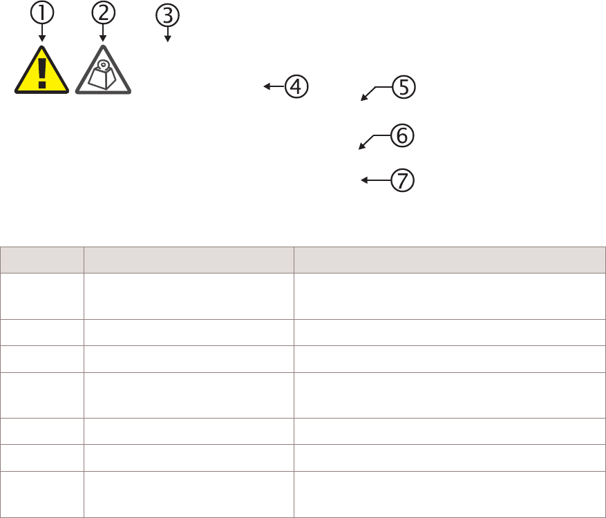
Structure of safety statements
Overview
This topic describes the components of safety statements that appear in this document.
General structure
Safety statements include the following structural elements:
Item Structure element Purpose
1 Safety alert symbol Indicates the potential for personal injury
(optional)
2 Safety symbol Indicates hazard type (optional)
3 Signal word Indicates the severity of the hazard
4 Hazard type Describes the source of the risk of damage or
injury
5 Safety message Consequences if protective measures fail
6 Avoidance message Protective measures to take to avoid the hazard
7 Identifier The reference ID of the safety statement
(optional)
SAMPLE
Lifting this equipment by yourself can result in injury
due to the size and weight of the equipment.
Always use three people or a lifting device to transport
and position this equipment. [ABC123]
CAUTION
Lifting hazard
Safety Structure of safety statements
....................................................................................................................................................................................................................................
....................................................................................................................................................................................................................................
1-2 Alcatel-Lucent – Internal
Proprietary – Use pursuant to Company instruction
9764 CMCO B41 2x6W
3MN-02026-0002-RJZZA
Issue 0.01 April 2015
P
RELIMINARY
P
RELIMINARY

Signal words
The signal words identify the hazard severity levels as follows:
Signal word Meaning
DANGER Indicates an extremely hazardous situation which, if not avoided, will
result in death or serious injury.
WARNING Indicates a hazardous situation which, if not avoided, could result in
death or serious injury.
CAUTION Indicates a hazardous situation which, if not avoided, could result in
minor or moderate injury.
NOTICE Indicates a hazardous situation not related to personal injury.
Safety Structure of safety statements
....................................................................................................................................................................................................................................
....................................................................................................................................................................................................................................
9764 CMCO B41 2x6W
3MN-02026-0002-RJZZA
Issue 0.01 April 2015
Alcatel-Lucent – Internal
Proprietary – Use pursuant to Company instruction 1-3
P
RELIMINARY
P
RELIMINARY

Safety
General precautions for installation procedures
WARNING
Failure to observe these safety precautions may result in personal
injury or damage to equipment.
•Read and understand all instructions.
•Follow all warnings and instructions marked on this product.
•Installation and maintenance procedures must be followed and performed by
trained personnel only.
•The equipment must be provided with a readily accessible disconnect device
as part of site preparation.
•Grounding and circuit continuity is vital for safe operation of the equipment.
Never operate the equipment with grounding/bonding conductor
disconnected.
•Install only equipment identified in the product's installation manual. Use of
other equipment may result in an improper connection which could lead to
fire or injury.
•Use caution when installing or modifying telecommunications lines.
•The product has multiple power inputs. Before servicing, Disconnect all
inputs to reduce the risk of energy hazards.
•For continued protection against risk of fire, all fuses used in this product
must be replaced only with fuses of the same type and rating.
•Never install telecommunications wiring during a lightning storm.
•Never install telecommunications connections in wet locations.
•Never touch uninsulated wiring or terminals carrying direct current or
ringing current, and never leave this wiring exposed. Protect and tape
uninsulated wiring and terminals to avoid risk of fire, electrical shock, and
injury to personnel.
•Never spill liquids of any kind on the product.
•To reduce the risk of an electrical shock, do not disassemble the product.
Opening and removing covers and/or circuit boards may expose you to
dangerous voltages or other risks. Incorrect reassembly can cause electrical
shock when the unit is subsequently used.
Safety Safety
....................................................................................................................................................................................................................................
....................................................................................................................................................................................................................................
1-4 Alcatel-Lucent – Internal
Proprietary – Use pursuant to Company instruction
9764 CMCO B41 2x6W
3MN-02026-0002-RJZZA
Issue 0.01 April 2015
P
RELIMINARY
P
RELIMINARY

Safety - specific hazards
DANGER
Electric-shock hazard
Working in severe weather can result in personal injury or death and damage to the
equipment.
Never install or perform maintenance during severe weather (high winds, lightning,
blizzards, hurricane etc.).
DANGER
Noxious-substance hazard
Use of unspecified cleaning agents can result in personal injury.
Use only specified cleaning agents. Never use flammable solvents.
Always ensure there is adequate ventilation in the work area and wear the appropriate
personal protective equipment.
WARNING
Electric-shock hazard
Some parts of all electrical installations are energized. Failure to observe this fact and
the safety warnings may lead to bodily injury and property damage.
For this reason, only trained and qualified personnel (electrical workers as defined in
IEC 60215 + A1 or EN 60215) may install or service the installation.
WARNING
Electric-shock hazard
The power supply lines to the network element are energized. Contact with parts carrying
voltage can cause health problems, possibly including death, even hours after the event.
Open and lockout the load disconnect switch in the distribution box to completely
de-energize the network element.
Safety Safety - specific hazards
....................................................................................................................................................................................................................................
....................................................................................................................................................................................................................................
9764 CMCO B41 2x6W
3MN-02026-0002-RJZZA
Issue 0.01 April 2015
Alcatel-Lucent – Internal
Proprietary – Use pursuant to Company instruction 1-5
P
RELIMINARY
P
RELIMINARY

WARNING
Electric-shock hazard
This product may be connected to an AC main power supply and may contain an internal
battery supply. Disconnecting one power source may not de-energize the system, and can
lead to serious injury.
Disconnect and lock out the AC main power supply, if present, and the internal battery
supply, if present, before servicing the equipment.
WARNING
Fall hazard
Falls can occur when working at heights resulting in serious personal injury or death.
To prevent a fall when working at heights (ladder, scaffold, manlift, roof, etc.) follow safe
work practices and wear appropriate fall protection equipment.
CAUTION
RF hazard
RF exposure in excess of applicable limits can result adverse health effects.
Metro Cells are designed and installed in order to comply with the international exposure
guidelines laid down by the International Commission on Non-Ionizing Radiation
Protection (ICNIRP) and/or the Institute of Electrical & Electronics Engineers (IEEE)
C95.1. ICNIRP guidelines have been implemented by the European Commission and a
number of other countries. IEEE guidelines have been implemented in North America and
some other countries.
Workers that are required to work in close proximity to the equipment, for example
maintenance personnel, should strictly follow instructions provided by their employer.
Workers equipped with personal medical electronic devices, such as pacemakers and
hearing aids, shall consult the manufacturer's instructions and consult their occupational
health practitioner.
Safety Safety - specific hazards
....................................................................................................................................................................................................................................
....................................................................................................................................................................................................................................
1-6 Alcatel-Lucent – Internal
Proprietary – Use pursuant to Company instruction
9764 CMCO B41 2x6W
3MN-02026-0002-RJZZA
Issue 0.01 April 2015
P
RELIMINARY
P
RELIMINARY

NOTICE
ESD hazard
Semiconductor devices can be damaged by electrostatic discharges.
The following rules must be complied with when handling any module containing
semiconductor components:
•Wear conductive or antistatic working clothes (for example, coat made of 100%
cotton).
•Wear the grounded wrist strap.
•Wear shoes with conductive soles on a conductive floor surface or conductive work
mat.
•Leave the modules in their original packaging until ready for use.
•Make sure there is no difference in potential between yourself, the workplace, and the
packaging before removing, unpacking, or packing a module.
•Hold the module only by the grip without touching the connection pins, tracks, or
components.
•Test or handle the module only with grounded tools on grounded equipment.
•Handle defective modules exactly like new ones to avoid causing further damage.
NOTICE
Condensation
Sudden changes in the weather may lead to the formation of condensation on
components. Operating the unit when condensation moisture is present can destroy the
unit.
Units which show signs of condensation must be dried before installation.
CAUTION
Laceration hazard
The RRH may have sharp edges and burrs and contact may cause cuts and lacerations.
Wear appropriate personal protective equipment.
Safety Safety - specific hazards
....................................................................................................................................................................................................................................
....................................................................................................................................................................................................................................
9764 CMCO B41 2x6W
3MN-02026-0002-RJZZA
Issue 0.01 April 2015
Alcatel-Lucent – Internal
Proprietary – Use pursuant to Company instruction 1-7
P
RELIMINARY
P
RELIMINARY

NOTICE
Tools
Tools left in the working area can cause short circuits during operation which can lead to
the destruction of units.
Make sure after finishing your work that no tools, testing equipment, flashlights, etc.,
have been left in or on the equipment.
NOTICE
Inadequate circulation
Inadequate circulation of cooling air can cause some units to become too warm. This can
lead to operational impairment.
Cover all installation slots for unequipped units with blanking panels.
CAUTION
Hot-surface hazard
The surfaces of the MRO can become hot enough to cause burns on unprotected skin. On
the product label, the universal symbol for Hot Surface (shown here) emphasizes this
hazard.
Before handling the unit, wait until its surfaces have cooled and, where the following
conditions apply, ensure that it is mounted out of the public's reach.
The 9768 MRO B38 shall operate normally with an ambient air temperature as low as
-40ºC and as high as 55ºC under a solar load of up to 1120 mW/m2.
NOTICE
Corrosive-substance hazard
Cleaning plastic containers and lids with abrasive and aggressive cleaning agents may
cause permanent damage.
Do not use solvents, paraffin, abrasive or aggressive cleaning fluids, abrasive or
aggressive antiseptic agents or abrasive or aggressive materials.
Safety Safety - specific hazards
....................................................................................................................................................................................................................................
....................................................................................................................................................................................................................................
1-8 Alcatel-Lucent – Internal
Proprietary – Use pursuant to Company instruction
9764 CMCO B41 2x6W
3MN-02026-0002-RJZZA
Issue 0.01 April 2015
P
RELIMINARY
P
RELIMINARY

NOTICE
Service-disruption hazard
Cleaning with water or a high-pressure cleaner may damage the components in the RRH.
The washing down of the equipment with water or a high-pressure cleaner is not
permitted.
Safety Safety - specific hazards
....................................................................................................................................................................................................................................
....................................................................................................................................................................................................................................
9764 CMCO B41 2x6W
3MN-02026-0002-RJZZA
Issue 0.01 April 2015
Alcatel-Lucent – Internal
Proprietary – Use pursuant to Company instruction 1-9
P
RELIMINARY
P
RELIMINARY
Product safety
Equipment safety
Safety information for this equipment can be found on various Caution, Warning, Danger,
information labels or instructions affixed to or included with the product or included
within this document. Informational and cautionary labels may appear near the item they
address or may be grouped in a single location on the equipment. Warnings are typically
adjacent to the hazard that is noted on the label. The instructions, cautions and warnings
found on these labels must be understood and observed by all personnel involved with the
equipment installation and maintenance.
Safety Product safety
....................................................................................................................................................................................................................................
....................................................................................................................................................................................................................................
1-10 Alcatel-Lucent – Internal
Proprietary – Use pursuant to Company instruction
9764 CMCO B41 2x6W
3MN-02026-0002-RJZZA
Issue 0.01 April 2015
P
RELIMINARY
P
RELIMINARY

22Product overview
Overview
Purpose
This chapter provides an overview of the Alcatel-Lucent 9764 Compact Metro Cell
Outdoor hardware and product functionality.
Contents
Functional description 2-2
Physical description 2-4
9764 CMCO weights and dimensions 2-11
Hardware and ancillary items 2-12
...................................................................................................................................................................................................................................
9764 CMCO B41 2x6W
3MN-02026-0002-RJZZA
Issue 0.01 April 2015
Alcatel-Lucent – Internal
Proprietary – Use pursuant to Company instruction 2-1
P
RELIMINARY
P
RELIMINARY
Functional description
General description
As a key component of high capacity networks, Alcatel-Lucent Metro Cells fill coverage
gaps between macro cells and provide indoor (and outdoor) coverage from indoor or
outdoor locations, enabling mobile network operators (MNOs) to deliver cost-effective
capacity to urban spots, as well as affordable coverage to suburban and rural locations.
Their essential usage is to deliver significantly higher capacity in places that need it,
contributing to enhancement of the quality of experience (QoE) for end users. It can also
complement or improve significantly the LTE macro layer coverage.
Alcatel-Lucent Metro Cells when used as components of heterogeneous networks
(HetNets), are compatible with both Alcatel-Lucent macro cells and 3rd party vendor
macro cells and integrate easily into any LTE network, without impacting the current
RAN deployment. The combination of macro eNodeB and 9764 MCO advanced
interference management features minimize any impact on macro network performance.
Product capabilities
The product capabilities in this release are:
•Supports LTE TDD
•Full B41, 2500 MHz frequency band.
•Optional directional or omnidirectional external antennas or Single or Dual Element
Antenna Module enabling higher throughput, lower interference and greater power
efficiency.
•Standard 2x2 MIMO configurations, 2 transmit and 2 receive diversity.
•The hardware is ready is ready for up to 3 LTE carriers.
•Supports traffic backhauled through the standard IP network. The product supports
two different SFP backhaul modules for different installation use-cases: one for daisy
chaining or one with PoE+ capability to power and backhaul any PoE+ compatible
external device.
•An individual field-replaceable unit (FRU) - as is the optional 9764 MCO Wi-Fi AP
module.
•Connecte to 3GPP EPC through standard S1 interfaces and can be connected to other
base stations using standard X2 interface.
Main characteristics
The MCO is designed as a small, lightweight unit virtually invisible to be used outdoor
and can be integrated in urban furniture or mounted on a lamppost, pole, or wall.
It is secured and plug-and play (allowing initial and on-going self-configuration).
Product overview Functional description
....................................................................................................................................................................................................................................
....................................................................................................................................................................................................................................
2-2 Alcatel-Lucent – Internal
Proprietary – Use pursuant to Company instruction
9764 CMCO B41 2x6W
3MN-02026-0002-RJZZA
Issue 0.01 April 2015
P
RELIMINARY
P
RELIMINARY

The main characteristics are:
Performances Characteristics
Transmit power 2 x 37.8 dBm (2x6W)
Typical antenna gain 7.5 dBi (Single Element Antenna module), 9.5 dBi
(Dual Element Antenna module)
Number of users supported 200 Simultaneous Active Users per carrier, up to 3
carriers
Supported bandwidth Up to 3 carriers of 10, 15 or 20 MHz
Throughput/Data rate speed in Mbps
(20 MHz)
HW capability: 112.45 DL / 9.6 UL L2 Frame
throughput, Frame Configurations 2 Special Sub Frame
7
Deployment scenarios
The 9764 CMCO may be deployed indoors or outdoors in public places and can be
mounted on walls, lamp posts, poles, or even on the side of a building in a vertical
orientation thanks to the Metro Compact Mounting Frame.
It can also be integrated in urban furniture such as bus shelter and information panels.
Optional tilt mounting brackets allow for the 9764 CMCO to be adjusted in vertical
and/or horizontal directions at same time, supporting:
•Up to +/- 30° vertical tilt (up/down) (from a purely mechanical perspective)
(CAVEAT: thermal specifications dictate maximum adjustment of +/- 20° vertical
tilt).
•Up to +/- 45° azimuth (side-to-side) adjustments.
Product overview Functional description
....................................................................................................................................................................................................................................
....................................................................................................................................................................................................................................
9764 CMCO B41 2x6W
3MN-02026-0002-RJZZA
Issue 0.01 April 2015
Alcatel-Lucent – Internal
Proprietary – Use pursuant to Company instruction 2-3
P
RELIMINARY
P
RELIMINARY
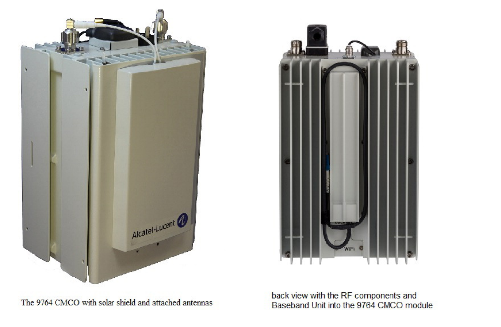
Physical description
Product overview
The Compact Metro Cell Outdoor concept targets to provide a common look and feel as
well as simplified installation and upgrade procedures. It brings new deployment
flexibility with its small dimensions and volume and its modular approach in RF and GPS
antennas, Wi-Fi access point (AP) and backhaul. Alcatel-Lucent’s innovative service
module design separates out.
Figure 2-1 9764 Compact Metro Cell Outdoor
Product overview Physical description
....................................................................................................................................................................................................................................
....................................................................................................................................................................................................................................
2-4 Alcatel-Lucent – Internal
Proprietary – Use pursuant to Company instruction
9764 CMCO B41 2x6W
3MN-02026-0002-RJZZA
Issue 0.01 April 2015
P
RELIMINARY
P
RELIMINARY
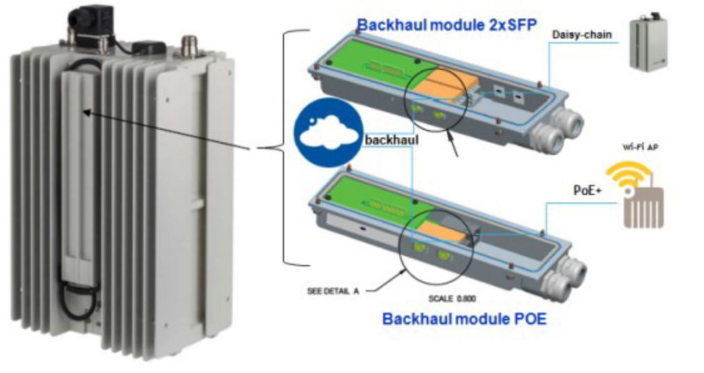
In order to simplify configurations the backhaul access function and the radio part
functions are separated, with a common interface as defined:
Unit Function Description
9764 CMCO Radio part function Radio functions
Digital processing functions
Power supply functions
Backhaul
module
Backhaul access function
Provides power to a remote Powered
Device (PD) for PoE+ case.
Two backhaul module variants:
•Dual SFP
•1 SFP/PoE+ RJ45
note: The RJ45 port of the backhaul
module PoE+ can only be used for
electrical backhaul connectivity. In a
future release, this port could be
available to connect a POE+ device
(WI-FI AP).
9764 MCO
Wi-Fi AP
module
Wi-Fi function Wi-Fi network access function
Refer to Alcatel-Lucent Small Cell
Wi-Fi AP Technical Description,
3MN-01840-0004-DEZZA for
Wi-Fi AP product details.
note: 9764 MCO Wi-Fi AP V1.0
does not support B7 and B41
Compact Metro Cell.
Figure 2-2 9764 Compact Metro Cell Outdoor with 9764 Wi-Fi AP
9764 Wi-Fi AP
9764 Wi-Fi AP 9764 MCO front view
with 9764 Wi-Fi AP
Product overview Physical description
....................................................................................................................................................................................................................................
....................................................................................................................................................................................................................................
9764 CMCO B41 2x6W
3MN-02026-0002-RJZZA
Issue 0.01 April 2015
Alcatel-Lucent – Internal
Proprietary – Use pursuant to Company instruction 2-5
P
RELIMINARY
P
RELIMINARY

Alcatel-Lucent 9764 Compact Metro Cell Outdoor overview
The Alcatel-Lucent 9764 Compact Metro Cell Outdoor is made up of three main units
which are responsible for radio, digital processing and power supply functions.
Unit Function
Modem board Digital part:
•Giga Ethernet switch
•Processors to provide modem and controller functionality
•Internal GPS/GLONASS Receiver for localization
synchronization
•9764 MCOWi-Fi AP interface
Radio Board Radio part:
•LTE Band 41
•Two external RF antenna connectors (Type N)
PSU (Power Supply Unit) Power supply part:
•Internal power module unit provides AC/DC conversion
(5.3 V output) to the Modem board (MEMO).
•The Modem board (MEMO) distributes 5.3 V output and
provides secondary DC-DC conversion to generate all
other (lower) voltages needed within the board.
Notes:
1. The 9764 CMCO is hardware ready for GLONASS satellite synchronization. Software
support for GLONASS synchronization will be added in a future release.
9764 CMCO connection interfaces
The following figure shows the connection interfaces for the 9764 CMCO :
Product overview Physical description
....................................................................................................................................................................................................................................
....................................................................................................................................................................................................................................
2-6 Alcatel-Lucent – Internal
Proprietary – Use pursuant to Company instruction
9764 CMCO B41 2x6W
3MN-02026-0002-RJZZA
Issue 0.01 April 2015
P
RELIMINARY
P
RELIMINARY
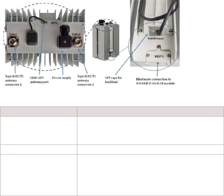
Connection location Description
9764 CMCO (top) Power supply connector
RF antenna connectors
QMA to external GPS antenna
9764 CMCO (bottom)1A blind mate connection to 9764 MCO Wi-Fi AP
9764 CMCO (back) Backhaul and daisy chaining ports via a backhaul module,
either
•Dual SFP backhaul module
•SFP/PoE+ RJ45 backhaul module
Notes:
1. The RJ45 port of the backhaul module PoE+ can only be used for electrical backhaul
connectivity. In a future release, this port could be available to connect a POE+ device
(WI-FI AP).
2. The Alcatel-Lucent 9764 Compact Metro Cell Outdoor can also support the Alcatel-Lucent
9764 MCO Wi-Fi Access Point, with restrictions: 9764 MCO Wi-Fi AP V1.0 does not
support B7 and B41 Compact Metro Cell.
Product overview Physical description
....................................................................................................................................................................................................................................
....................................................................................................................................................................................................................................
9764 CMCO B41 2x6W
3MN-02026-0002-RJZZA
Issue 0.01 April 2015
Alcatel-Lucent – Internal
Proprietary – Use pursuant to Company instruction 2-7
P
RELIMINARY
P
RELIMINARY

Power supply
The 9764 CMCO product is orderable as an option to support either AC or DC power
input.
9764 CMCO Power supply details
AC variant AC power supply that operates from a single phase, three wire voltage
source in the 85 to 270 Volt range. Product rated voltage range is 110 to
240 Volt.
The AC power is surge-protected and conforms to ETSI EN 301-489-1
V1.9.2 section 9.8 and GR-1089-CORE Issue 6 port type 7.
Fully configured and operating at maximum levels, the product
dissipates less than 150 W
DC variant -48 V DC power supply that operates over the voltage range from -40 V
DC to -57 V DC. For first start-up -45 Volts +/- 3 Volts is required.
Fully configured and operating at maximum levels, the product
dissipates less than 150 W
Backhaul interface
The following two backhaul (BH) configurations are supported on the 9764 CMCO:
•Dual SFP, where
– Each SFP can be either GigE (electrical or optical) or GPON
– Can be used for daisy chain configurations, where the SFP in the 2nd BH port
must be optical
•SFP and Power over Ethernet (PoE)+ (IEEE 802.3at), where
– The single SFP can be either GigE (electrical or optical) or GPON
– The PoE+ backhaul module powers a PoE+ capable Powered Device (PD), e.g. a
wireless backhaul. This interface provides up to 25.5 W of power to the remotely
connected PD.
– It can support a daisy chain configurations to other MCOs in the SFP port when
the PoE+ port is used for wireless backhaul.
Note: if the CMCO is the 2nd module of a daisy-chain, the first port SFP is not used
for BH connection but used for daisy-chain and then it supports only GBE or CPRI
optical.
Up to two 9764 CMCOs may be daisy-chained. If two 9764 CMCO are
daisy-chained, the BH module POE+ can be used for “Head-CMCO” only
Note: Backhaul module POE+ is not supported by 9764 CMCO B41 2x6W units.
Product overview Physical description
....................................................................................................................................................................................................................................
....................................................................................................................................................................................................................................
2-8 Alcatel-Lucent – Internal
Proprietary – Use pursuant to Company instruction
9764 CMCO B41 2x6W
3MN-02026-0002-RJZZA
Issue 0.01 April 2015
P
RELIMINARY
P
RELIMINARY
RF antenna
The 9764 CMCO supports two external antenna connectors (Type N) on the top of the
enclosure supporting an antenna module in the following configurations:
•Attached RF antennas mounted on the side of the 9764 CMCO
•Cabling to external remote RF antennas
Note: When deploying a 9764 CMCO with remote LTE antennas and a Wi-Fi AP
module, antenna isolation between the remote external LTE antennas and the Wi-Fi
AP module antennas must be at least -42 dB.
Refer to the RF antennas part of the System architecture topic of the Alcatel-Lucent 9764
Compact Metro Cell Outdoor Technical Description for more RF antenna information.
GPS/GLONASS Antenna
The 9764 CMCO supports an external GPS/GLONASS antenna connector (QMA) on the
top of the enclosure allowing the following GPS/GLONASS antenna configurations:
•Attached GPS/GLONASS antenna mounted on the top of the 9764 CMCO
•Cabling to an external remote GPS antenna
Figure 2-3 Backhaul module variants
Product overview Physical description
....................................................................................................................................................................................................................................
....................................................................................................................................................................................................................................
9764 CMCO B41 2x6W
3MN-02026-0002-RJZZA
Issue 0.01 April 2015
Alcatel-Lucent – Internal
Proprietary – Use pursuant to Company instruction 2-9
P
RELIMINARY
P
RELIMINARY
This attached GPS/Glonass antenna is connected via a 70cm long cable to the QMA
connector located on the top or the MCO housing. In case the 9764 CMCO shall be
mounted up side down the antenna can be relocated to a position visible to the satellites.
Note: The 9764 CMCO is hardware ready for GLONASS satellite synchronization.
Software support for GLONASS synchronization will be added in a future release.
Status indicators
The 9764 CMCO supports a single bi-color LED (red/green) which is located on the rear
lower portion of the casing. The LED is not intended for use during normal operation of
the equipment; however, it can provide a visual status of the equipment during initial
installation and commissioning.
Product labelling
A 9764 CMCO product label provides the following information:
•Model name
•Part number
•Serial number
•MAC address
•Power input range
•CE Approval marking
•Environmental marking (WEEE/RoHS) applicable to the device
Product overview Physical description
....................................................................................................................................................................................................................................
....................................................................................................................................................................................................................................
2-10 Alcatel-Lucent – Internal
Proprietary – Use pursuant to Company instruction
9764 CMCO B41 2x6W
3MN-02026-0002-RJZZA
Issue 0.01 April 2015
P
RELIMINARY
P
RELIMINARY

9764 CMCO weights and dimensions
Weights and dimensions
This topic covers the 9764 CMCO weights and dimensions.
Standard MRO weights and dimensions
The following table provides weights and dimensions for the 9764 CMCO.
9764 CMCO
configuration
Volume
litres
Weight
kg
Sizes (LxWxD)
mm
9764 CMCO <7.5 L 7.3 kg 265 x 180 x 156.5mm
Product overview 9764 CMCO weights and dimensions
....................................................................................................................................................................................................................................
....................................................................................................................................................................................................................................
9764 CMCO B41 2x6W
3MN-02026-0002-RJZZA
Issue 0.01 April 2015
Alcatel-Lucent – Internal
Proprietary – Use pursuant to Company instruction 2-11
P
RELIMINARY
P
RELIMINARY
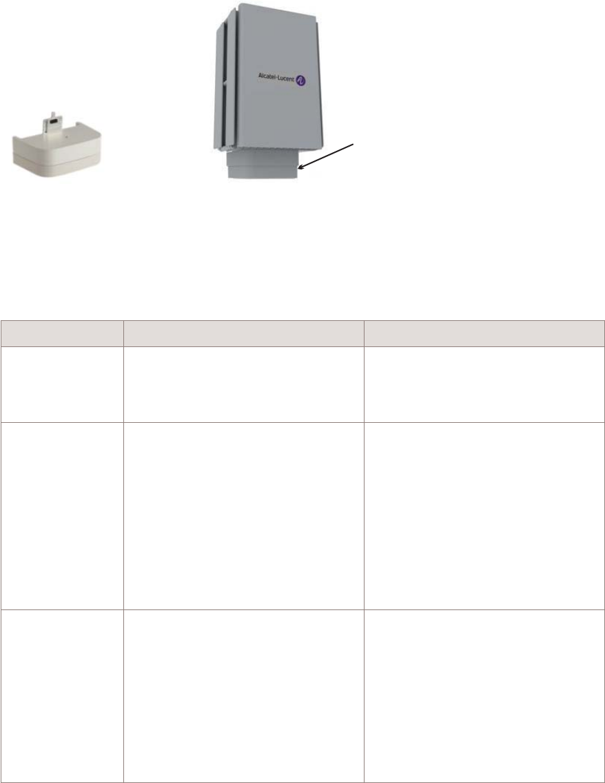
Hardware and ancillary items
Overview
The following section describes the supported installation options for the 9764 CMCO
product. These include:
•Standard installation options for all 9764 CMCO products
•Daisy chain installation options where two 9764 CMCO modules are daisy chained
together and share the same backhaul port
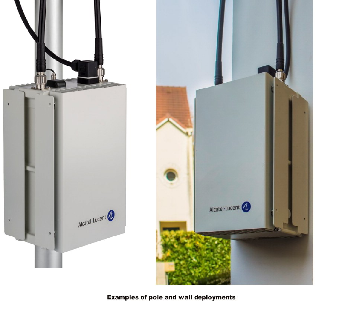
Standard installation options
9764 MCO products are designed to be deployed outdoors and close to the users, usually
on light poles or lamp posts in streets or on building walls, with a vertical profile.
In addition, the 9764 CMCO can be fitted with an optional Alcatel-Lucent 9764 Metro
Cell Outdoor Wi-Fi AP.
Note: 9764 MCO Wi-Fi AP V1.0 does not support B41 Metro Cells.
Figure 2-4 Installation examples
Product overview Hardware and ancillary items
....................................................................................................................................................................................................................................
....................................................................................................................................................................................................................................
2-12 Alcatel-Lucent – Internal
Proprietary – Use pursuant to Company instruction
9764 CMCO B41 2x6W
3MN-02026-0002-RJZZA
Issue 0.01 April 2015
P
RELIMINARY
P
RELIMINARY
Refer to Alcatel-Lucent Small Cell Wi-Fi AP Technical Description, 3MN-01840-0004-
DEZZA for Wi-Fi AP product details.
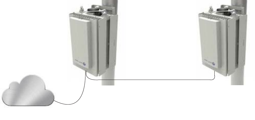
Ethernet daisy chain installation options
In a daisy chain installation configuration two 9764 MCOs can be daisy chained together,
where they share the same backhaul port, thus reducing the investment cost needed to
connect the 9764 MCO s to the backhaul network and aggregating the uplink and
downlink traffic. Daisy chained 9764 MCO s may be co-located or separated by some
distance. The actual distance depends upon the SFP and Ethernet cable configuration used
for the daisy chain. Maximum distance is 100 m when using electrical Ethernet cable and
300 m when using optical Ethernet cable. Refer to, “Hardware and ancillary items” for
supported SFPs and Ethernet cable types and lengths.
If a 9764 MCO is to be included in the daisy chain configuration, the following Wi-Fi AP
configurations are supported:
•A 9764 MCO can be attached to each daisy chained 9764 MCO when the daisy
chained MCOs are installed in separate locations (e.g., not co-located on the same
pole).
•If the daisy chained 9764 MCO are co-located, only one 9764 MCO can be used, and
the 9764 MCO can be attached to either MCO.
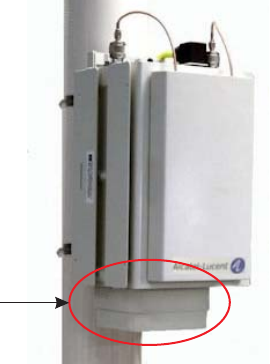
Figure 2-5 9764 MCO Wi-Fi AP module attached to 9764 CMCO (front view)
Wi-Fi AP
Product overview Hardware and ancillary items
....................................................................................................................................................................................................................................
....................................................................................................................................................................................................................................
9764 CMCO B41 2x6W
3MN-02026-0002-RJZZA
Issue 0.01 April 2015
Alcatel-Lucent – Internal
Proprietary – Use pursuant to Company instruction 2-13
P
RELIMINARY
P
RELIMINARY
Street furniture installation
The 9764 MCO can be installed as part of street furniture, for example, bus stops and
advertising boards, to further improve the quality of service provided to users in high
density areas such as city centers.
9764 CMCO base items
The product packaging contains the following base items:
•9764 CMCO (including “attached” GPS/GLONASS antenna)
•9764 CMCO configured backhaul module variant (not attached to the 9764 CMCO )
•9764 CMCO mounting bracket
•9764 CMCO basic installation kit
Note: The 9764 CMCO is hardware ready for GLONASS satellite synchronization.
Software support for GLONASS synchronization will be added in a future release.
9764 MCO Wi-Fi AP base items
The Alcatel-Lucent 9764 Metro Cell Outdoor Wi-Fi AP is an option product. It supports
the Alcatel-Lucent 9764 MCO Wi-Fi Access Point with restrictions:
•9764 MCO Wi-Fi AP V1.0 does not support B7 and B41 Compact Metro Cell.
Figure 2-6 9764 MCO daisy chain installation example
Backhaul
Product overview Hardware and ancillary items
....................................................................................................................................................................................................................................
....................................................................................................................................................................................................................................
2-14 Alcatel-Lucent – Internal
Proprietary – Use pursuant to Company instruction
9764 CMCO B41 2x6W
3MN-02026-0002-RJZZA
Issue 0.01 April 2015
P
RELIMINARY
P
RELIMINARY

Ancillary items
The following tables list the ancillary items that are available for order from
Alcatel-Lucent in support of the defined equipment installation and configuration options.
Installation kits
The following table list the installation kits that are available for order from
Alcatel-Lucent in support of the equipment installation options.
Installation kit Description Use
Vertical tilt installation kit Vertical tilt bracket Mandatory:
•pole mount with tilt
•wall mount: with vertical only
•wall mount: with vertical and
horizontal tilt
Horizontal tilt installation kit Horizontal tilt bracket Mandatory:
•wall mount: with horizontal tilt only
•wall mount: with horizontal and
vertical tilt
Banding kit Stainless steel bands
Band buckles (Ear-Lokt)
Mandatory:
•pole mount only
Banding tool Standard BAND-IT®Banding Tool
(CR00169), including operating
instructions
Mandatory:
•use with the Banding kit for pole
mount only
Power
Item Description Use
Power connector (AC) AC power connector Required for 9764 CMCO module with
AC power (International markets)
Power connector (DC) DC power connector Required for 9764 CMCO module with
DC power (International markets)
Power cable Power cable IN/OUT 3G1,5mm²,
100m roll or multiples of 1m length
(as needed)
Required for 9764 CMCO module
(International markets)
Power cable (AC) Power cable pre-assembled with AC
power connector, various lengths
(2m. 4.5m, 9m, 12m)
Required for 9764 CMCO module with
AC power (North America Regional
markets)
Power cable (DC) Power cable pre-assembled with DC
power connector, various lengths
(2m. 4.5m, 9m, 12m)
Required for 9764 CMCO module with
DC power (North America Regional
markets)
Product overview Hardware and ancillary items
....................................................................................................................................................................................................................................
....................................................................................................................................................................................................................................
9764 CMCO B41 2x6W
3MN-02026-0002-RJZZA
Issue 0.01 April 2015
Alcatel-Lucent – Internal
Proprietary – Use pursuant to Company instruction 2-15
P
RELIMINARY
P
RELIMINARY

Grounding
Item Description Use
Ground cable Ground cable,Y/G 10mm² in 100m
roll
Required for International markets
Ground cable Ground cable, 8 AWG Required for North America Regional
markets
Backhaul modules
Item Description Use
Dual SFP 2 x SFP, where each SFP can be
either GigE (electrical or optical) or
GPON
Mandatory
One backhaul module variant required per
9764 CMCO
SFP/PoE+ SFP and Power over Ethernet (PoE)+,
where the single SFP can be either
GigE (electrical or optical) or GPON
and the PoE+ port powers a PoE+
capable Powered Device (PD)
SFP modules
Item Description Use
SFP module SFP GBE 10/100/1000BaseT
(copper)
Optional
Electrical backhaul only
SFP module SFP GBE 1000BaseLX (Single
mode)
Optional
Optical backhaul, Daisy chaining
SFP module SFP GBE 1000BaseLX / CPRI
(Single mode)
Optional
Optical backhaul, Daisy chaining
SFP module SFP GBE 1000BaseSX / CPRI (Multi
mode)
Optional
Optical backhaul, Daisy chaining
SFP module GPON SFP Optional
Optical backhaul only
RF antenna
Item Description Use
2.6 GHz RF antenna 2.6 GHz (Band 7), 70° x 35° HPBW,
gain 10-11 dBi
Optional
Use for attached RF antenna configuration
1.7 to 2.1 GHz RF antenna 1.7 to 2.1 GHz (Band 3), 70° x 70°
HPBW, gain 7-8 dBi
Optional
Use for attached RF antenna configuration
Product overview Hardware and ancillary items
....................................................................................................................................................................................................................................
....................................................................................................................................................................................................................................
2-16 Alcatel-Lucent – Internal
Proprietary – Use pursuant to Company instruction
9764 CMCO B41 2x6W
3MN-02026-0002-RJZZA
Issue 0.01 April 2015
P
RELIMINARY
P
RELIMINARY

External antenna - GPS
Item Description Use
GPS antenna External GPS Antenna, 1575
MHz*26 dBi
Used if 9764 CMCO is configured for
external GPS antenna and cable loss
<10dBi @ 1575MHz
GPS antenna External GPS Antenna, 1575
MHz*40 dBi
Used if 9764 CMCO is configured for
external GPS antenna and cable loss
>10dBi @ 1575MHz
Jumper cable External GPS Antenna jumper cable
(2m, 5m, 15m)
Mandatory
1 cable per 9764 CMCO if external GPS
antenna is used (International markets)
Jumper cable External GPS Antenna jumper cable
(36ft, 60ft)
Mandatory
1 cable per 9764 CMCO if external GPS
antenna is used (North America Regional
markets)
Adapter cable External GPS Antenna adaptor cable Mandatory
1 cable per 9764 CMCO if external GPS
antenna is used
Surge arrestor
Item Description Use
Surge arrestor External Ethernet surge arrestor Optional
Highly recommended if GBE 1000BaseT
backhaul connection is provided
Surge arrestor kit External Ethernet surge arrestor kit,
including:
•mounting bracket
•pole bands and buckle
•Ethernet cable, 0.6 m (2 ft)
Required for External surge arrestor
Ethernet cable - Electrical
Item Description Use
Electrical Ethernet cable 2m, 25m, 100m outdoor, 4 pairs, 2
RJ45 (plus 1 spare)
Optional
Use with SFP GBE 10/100/1000BaseT
(International markets)
Electrical Ethernet cable 2m, 25m, 100m outdoor, 4 pairs, 2
RJ45 (plus 1 spare)
Optional
Use with SFP GBE 10/100/1000BaseT
(North America Regional markets)
Product overview Hardware and ancillary items
....................................................................................................................................................................................................................................
....................................................................................................................................................................................................................................
9764 CMCO B41 2x6W
3MN-02026-0002-RJZZA
Issue 0.01 April 2015
Alcatel-Lucent – Internal
Proprietary – Use pursuant to Company instruction 2-17
P
RELIMINARY
P
RELIMINARY

Electrical Ethernet cable – Specifications
When selecting Ethernet cables, the following requirements must be taken into account:
Item Description Use
Electrical Ethernet cable Cathegory: CAT5e and CAT6 support
1 Gigabit/s
Shielding types: S/UTP and SF/UTP:
Optional
Use with SFP GBE 10/100/1000BaseT
Ethernet cable - Optical
Item Description Use
Fiber Optic cable SMDF LC-LC 2SM 1m Optional
Single mode fiber duplex. 80mm/80mm
Breakout, Outer diameter: 5.5mm
Use for Single Mode link (select cable
length)
Fiber Optic cable SMDF LC-LC 2SM 2.5m
Fiber Optic cable SMDF LC-LC 2SM 5m
Fiber Optic cable SMDF LC-LC 2SM 15m
Fiber Optic cable SMDF LC-LC 2SM 30m
Fiber Optic cable SMDF LC-LC 2SM 50m
Fiber Optic cable SMDF LC-LC 2SM 70m
Fiber Optic cable SMDF LC-LC 2SM 85m
Fiber Optic cable SMDF LC-LC 2SM 100m
Fiber Optic cable SMDF LC-LC 2SM 150m
Fiber Optic cable SMDF LC-LC 2SM 200m
Fiber Optic cable SMDF LC-LC 2SM 250m
Fiber Optic cable SMDF LC-LC 2SM 300m
Product overview Hardware and ancillary items
....................................................................................................................................................................................................................................
....................................................................................................................................................................................................................................
2-18 Alcatel-Lucent – Internal
Proprietary – Use pursuant to Company instruction
9764 CMCO B41 2x6W
3MN-02026-0002-RJZZA
Issue 0.01 April 2015
P
RELIMINARY
P
RELIMINARY

Item Description Use
Fiber Optic cable MM LC-LC 2MM 1m Optional
Multi Mode fiber duplex. 80mm/80mm
Breakout, Outer diameter: 5.5mm
Use for Multi Mode link (select cable
length)
Fiber Optic cable MM LC-LC 2MM 2.5m
Fiber Optic cable MM LC-LC 2MM 5m
Fiber Optic cable MM LC-LC 2MM 10m
Fiber Optic cable MM LC-LC 2MM 15m
Fiber Optic cable MM LC-LC 2MM 30m
Fiber Optic cable MM LC-LC 2MM 50m
Fiber Optic cable MM LC-LC 2MM 70m
Fiber Optic cable MM LC-LC 2MM 85m
Fiber Optic cable MM LC-LC 2MM 100m
Fiber Optic cable MM LC-LC 2MM 150m
Fiber Optic cable MM LC-LC 2MM 200m
Fiber Optic cable MM LC-LC 2MM 250m
Fiber Optic cable MM LC-LC 2MM 300m
Solar shield
Item Description Use
Solar shield Solar Shield for Compact MCO Optional
Product overview Hardware and ancillary items
....................................................................................................................................................................................................................................
....................................................................................................................................................................................................................................
9764 CMCO B41 2x6W
3MN-02026-0002-RJZZA
Issue 0.01 April 2015
Alcatel-Lucent – Internal
Proprietary – Use pursuant to Company instruction 2-19
P
RELIMINARY
P
RELIMINARY
Product overview Hardware and ancillary items
....................................................................................................................................................................................................................................
....................................................................................................................................................................................................................................
2-20 Alcatel-Lucent – Internal
Proprietary – Use pursuant to Company instruction
9764 CMCO B41 2x6W
3MN-02026-0002-RJZZA
Issue 0.01 April 2015
P
RELIMINARY
P
RELIMINARY

33Pre-installation
Overview
Purpose
This chapter provides pre-installation information (including required tools and materials
and installation clearances) as well as outlining the possible daisy chain deployment
scenarios and requirements for the Alcatel-Lucent 9764 Compact Metro Cell Outdoor
product.
Contents
Pre-installation information 3-2
Installation clearances 3-4
Pole mount installation requirements 3-5
Wall mount installation requirements 3-7
Daisy chain requirements 3-9
...................................................................................................................................................................................................................................
9764 CMCO B41 2x6W
3MN-02026-0002-RJZZA
Issue 0.01 April 2015
Alcatel-Lucent – Internal
Proprietary – Use pursuant to Company instruction 3-1
P
RELIMINARY
P
RELIMINARY
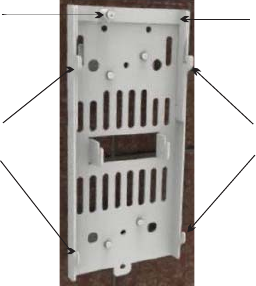
Pre-installation information
Verify site preparation
The following site preparation requirements should be checked and met before the
installation of the equipment can begin. If some of the requirements are not met, the
installer must do so now:
•Ensure equipment is planned to be installed as high as possible to avoid obstructions.
•Consider nearby sources of interference. Also check possibility of future obstructions.
•Ensure adequate clearance is provided for service access.
•Ground, power and backhaul cabling has been routed and is in place.
•Ensure any site specific fixing materials (screws, washers, wall plugs) for pole/wall
mounting the equipment are available.
Product delivery contents
Unpack and examine the product packaging contents. If you notice any damage, or
missing items as listed in the Packing List, immediately notify the carrier that delivered
the unit and contact your Alcatel-Lucent representative.
The product packaging contains the following items:
•The Alcatel-Lucent 9764 Compact Metro Cell Outdoor
Installation materials
In addition to the standard product deliverable ensure the appropriate mounting brackets,
installation kits and ancillary items are available to support the product mounting options.
Figure 3-1 Mounting bracket
Locking screw Hinged plate
Compact MCO
mounting lugs
Compact MCO
mounting lugs
Pre-installation Pre-installation information
....................................................................................................................................................................................................................................
....................................................................................................................................................................................................................................
3-2 Alcatel-Lucent – Internal
Proprietary – Use pursuant to Company instruction
9764 CMCO B41 2x6W
3MN-02026-0002-RJZZA
Issue 0.01 April 2015
P
RELIMINARY
P
RELIMINARY

Table 3-1 Recommended wall anchor materials
Surface structure Recommended anchor materials Recommended screw torque
Wood Screw Hex T M8x70 stainless steel (x4)
Washer plain M8x16x1.6 stainless steel (x4)
7.0 N.m (62.0 lb.in).
Concrete Screw CHC M6x80 stainless steel (x4)
Washer plain M6x12x1.6mm stainless steel (x4)
Washer spring M6x12x1.2mm stainless steel (x4)
Plug expansion Rawlnut M6x50 (x4)
7.0 N.m (62.0 lb.in).
Tools required for installation
The following tools may be used during installation:
•Drill (pneumatic hammer) and assorted drill bits
•Pliers
•Adjustable spanners
•M17 socket wrench
•Screwdrivers (power and/or manual):
– Phillips (flat blade)
– Torx (T-25 and T-40)
•HRS (Hirose) HT206/TM21p-88p crimping tool (for RJ45 cable)
•Data cable tester for shielded RJ45 (optional)
•Measuring tape
•Digital compass (to aid establishing product orientation)
•Marker, to mark wall mounting holes
•Vacuum cleaner or equivalent (required for clearing debris from wall mounting holes)
•Spirit level
•Hammer
•PIB (self-amalgamating) tape and 3M Super 33+ vinyl tape
•Ear protectors and safety goggles/glasses
•Assorted cable ties (various lengths)
•Heavy duty tape
•Adjustable straps
Pre-installation Pre-installation information
....................................................................................................................................................................................................................................
....................................................................................................................................................................................................................................
9764 CMCO B41 2x6W
3MN-02026-0002-RJZZA
Issue 0.01 April 2015
Alcatel-Lucent – Internal
Proprietary – Use pursuant to Company instruction 3-3
P
RELIMINARY
P
RELIMINARY
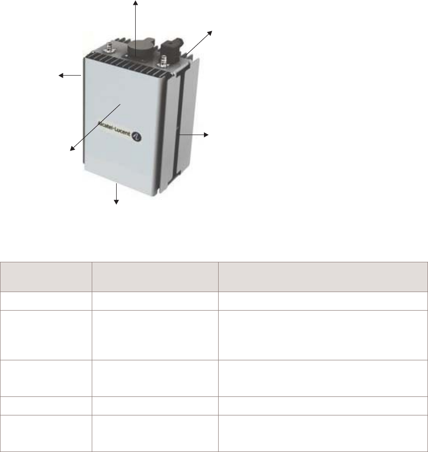
Installation clearances
Minimum installation clearances
The following provides the minimum wall mount clearances recommended around the
9764 CMCO B41 2x6W.
Metro Cell
Outdoor
Clearances mm
(inches)
Comment
Side(s) 400 mm (15.75 inch) Access to secure the solar shield cover.
Top 400 mm (15.75 inch) Access to cable connections and cable
bending radius.
To aid natural air convection.
Bottom 400 mm (15.75 inch) Access to connections (Wi-Fi AP).
To aid natural air convection.
Front 460 mm (18.11 inch) Access to secure the solar shield cover.
Rear 20 mm (0.79 inch) For the wall mounting space.
To aid natural air convection.
Figure 3-2 9764 CMCO B41 2x6W installation clearances
Rear clearance
20mm (0.79in)
Front clearance
460mm (18.11in)
Bottom clearance
400mm (15.75in)
Side clearance
400mm (15.75 in)
Top clearance
400mm (15.75in)
Side clearance
400mm (15.75 in)
Pre-installation Installation clearances
....................................................................................................................................................................................................................................
....................................................................................................................................................................................................................................
3-4 Alcatel-Lucent – Internal
Proprietary – Use pursuant to Company instruction
9764 CMCO B41 2x6W
3MN-02026-0002-RJZZA
Issue 0.01 April 2015
P
RELIMINARY
P
RELIMINARY

Pole mount installation requirements
Purpose
This topic outlines the basic requirements, installation kits and recommended anchor
materials when mounting the Alcatel-Lucent 9764 Compact Metro Cell Outdoor directly
onto a pole, onto tilt brackets or onto a pair mount bracket.
Pole mount options
The 9764 CMCO can be easily mounted onto a pole for the following installation options:
•9764 CMCO banded onto a pole (without the tilt option).
The 9764 CMCO mounting bracket and pole band installation kit is used.
•9764 CMCO attached to the vertical tilt bracket. Vertical tilt bracket is banded onto a
pole.
The vertical tilt bracket, 9764 CMCO mounting bracket and pole band installation kit
is used.
Pole mount installation kits and brackets
The following table provides the installation kits and brackets that can be used, depending
on the deployment scenario, for 9764 CMCO pole mounting.
Table 3-2 Pole mount installation kits and brackets
Item Description
9764 MCO Compact mounting bracket Required for attaching the 9764 CMCO directly onto a pole or vertical tilt
bracket
Vertical tilt bracket Provides +/- 30° vertical tilt (up/down) adjustment
Banding kit Required when directly attaching the 9764 CMCO or vertical tilt bracket
to a pole (diameter 50 to 300 mm) using stainless steel bands.
Stainless steel bands and buckles (Ear-Lokt)
Banding tool Standard BAND-IT®Banding Tool (CR00169), including operating
instructions
Required in order to tighten stainless steel metal bands
The following figure shows the brackets used for pole mount installation, depending on
the deployment scenario.
Pre-installation Pole mount installation requirements
....................................................................................................................................................................................................................................
....................................................................................................................................................................................................................................
9764 CMCO B41 2x6W
3MN-02026-0002-RJZZA
Issue 0.01 April 2015
Alcatel-Lucent – Internal
Proprietary – Use pursuant to Company instruction 3-5
P
RELIMINARY
P
RELIMINARY
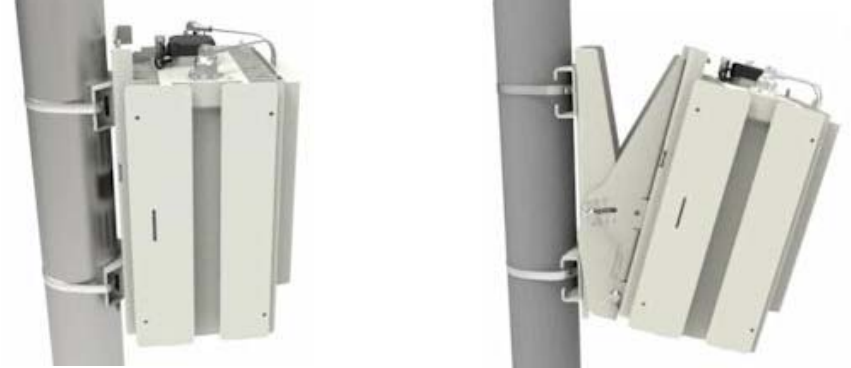
Figure 3-3 Pole mount banding and brackets
Pole mount no tilt Pole mount with tilt
Pre-installation Pole mount installation requirements
....................................................................................................................................................................................................................................
....................................................................................................................................................................................................................................
3-6 Alcatel-Lucent – Internal
Proprietary – Use pursuant to Company instruction
9764 CMCO B41 2x6W
3MN-02026-0002-RJZZA
Issue 0.01 April 2015
P
RELIMINARY
P
RELIMINARY

Wall mount installation requirements
Purpose
This topic outlines basic requirements, installation kits and recommended anchor
materials when mounting the Alcatel-Lucent 9764 Compact Metro Cell Outdoor onto a
solid concrete wall or flat surface or onto tilt brackets.
Wall mount options
The 9764 CMCO can be easily mounted onto any flat, sturdy wall for the following
installation options:
•9764 CMCO attached directly onto a wall or flat surface.
•9764 CMCO attached to the vertical/horizontal tilt bracket(s). Vertical/horizontal tilt
bracket(s) are attached to a wall.
Wall mount installation brackets and kits
The following table lists the installation brackets that can be used, depending on the
deployment scenario, for 9764 CMCO wall mounting.
Table 3-3 Wall mount installation brackets
Item Description
9764 CMCO mounting bracket Required when attaching the 9764 CMCO directly to a wall or flat surface
or onto tilt brackets.
Vertical tilt bracket Provides +/- 30° vertical tilt (up/down) adjustment
Note: Can be used in combination with the horizontal installation kit to
provide:
•+/- 30° vertical tilt (up/down) adjustment, and
•+/-45° horizontal tilt (left/right) adjustment
Horizontal tilt bracket Provides +/-45° horizontal tilt (left/right) adjustment
Note: Can be used in combination with the vertical tilt installation kit to
provide:
•+-45° horizontal tilt (left/right) adjustment, and
•+/- 30° vertical tilt (up/down) adjustment
Pre-installation Wall mount installation requirements
....................................................................................................................................................................................................................................
....................................................................................................................................................................................................................................
9764 CMCO B41 2x6W
3MN-02026-0002-RJZZA
Issue 0.01 April 2015
Alcatel-Lucent – Internal
Proprietary – Use pursuant to Company instruction 3-7
P
RELIMINARY
P
RELIMINARY
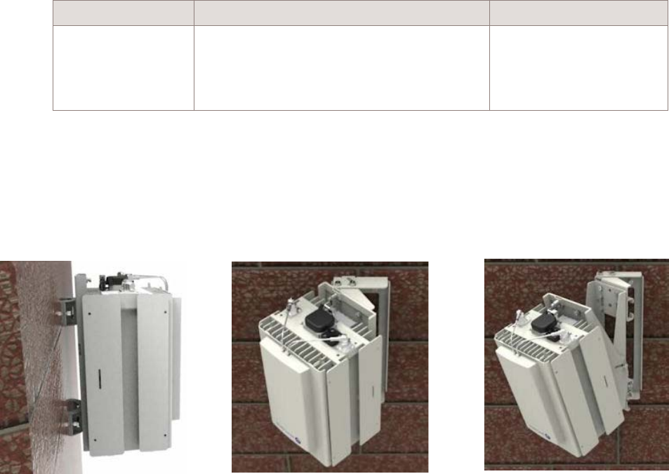
Recommended wall anchor materials
Surface structure Recommended anchor materials Recommended screw torque
Concrete Screw CHC M6x80 stainless steel (x3)
Washer plain M6x12x1.6mm stainless steel (x3)
Washer spring M6x12x1.2mm stainless steel (x3)
Plug expansion Rawlnut M6x50 (x3)
7.0 N.m (62.0 lb.in).
Wall mount installation examples
The following figures show examples of 9764 CMCO wall mount installation and wall
mount installation with horizontal/vertical tilt.
Figure 3-4 9764 CMCO wall mount examples
Wall mount no tilt Wall mount horizontal tilt only Wall mount horizontal
and vertical tilt
Pre-installation Wall mount installation requirements
....................................................................................................................................................................................................................................
....................................................................................................................................................................................................................................
3-8 Alcatel-Lucent – Internal
Proprietary – Use pursuant to Company instruction
9764 CMCO B41 2x6W
3MN-02026-0002-RJZZA
Issue 0.01 April 2015
P
RELIMINARY
P
RELIMINARY
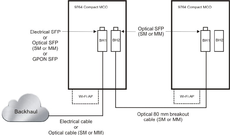
Daisy chain requirements
Overview
Two 9764 MCOs can be daisy chained together to share the same backhaul port, thus
reducing the investment cost needed to connect the 9764 MCOs to the backhaul network
and aggregating the uplink traffic. Daisy chain connectivity scenarios support 9764
MCOs that are co-located and connected together or 9764 MCOs that are separated by
some distance.
Daisy chaining configurations
A maximum of two 9764 MCO modules and a single Wi-Fi Access Point may be daisy
chained together.
The 9764 MCO supports the following daisy chain configurations:
•A 9764 MCO connected to the backhaul network plus a 9764 MCO connected to the
daisy chain port of the “head” 9764 MCO.
•A 9764 MCO connected to the backhaul network plus a 9764 MCO WCDMA module
connected to the daisy chain port of the “head” 9764 MCO.
Pre-installation Daisy chain requirements
....................................................................................................................................................................................................................................
....................................................................................................................................................................................................................................
9764 CMCO B41 2x6W
3MN-02026-0002-RJZZA
Issue 0.01 April 2015
Alcatel-Lucent – Internal
Proprietary – Use pursuant to Company instruction 3-9
P
RELIMINARY
P
RELIMINARY
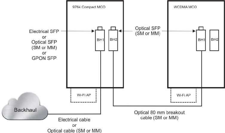
Note: An optional single Wi-Fi Access Point may be attached to either the MCO
connected to the backhaul network or the MCO that is daisy chained.
Pre-installation Daisy chain requirements
....................................................................................................................................................................................................................................
....................................................................................................................................................................................................................................
3-10 Alcatel-Lucent – Internal
Proprietary – Use pursuant to Company instruction
9764 CMCO B41 2x6W
3MN-02026-0002-RJZZA
Issue 0.01 April 2015
P
RELIMINARY
P
RELIMINARY

44Installation
Overview
Purpose
This chapter provides the instructions for:
•Cabling the MCO Compact backhaul module before installing the Alcatel-Lucent
9764 Compact Metro Cell Outdoor.
•Mounting the 9764 CMCO onto either a pole or wall with or without the optional tilt
mechanism.
Contents
Pre-installation cabling 4-2
Ethernet cabling - fiber optic 4-3
Ethernet cabling - electrical 4-9
Installation 4-17
Pole mount the 9764 CMCO 4-18
Pole mount the 9764 CMCO using optional tilt brackets 4-24
Wall mount the 9764 CMCO 4-32
Wall mount the 9764 CMCO using optional tilt brackets 4-38
...................................................................................................................................................................................................................................
9764 CMCO B41 2x6W
3MN-02026-0002-RJZZA
Issue 0.01 April 2015
Alcatel-Lucent – Internal
Proprietary – Use pursuant to Company instruction 4-1
P
RELIMINARY
P
RELIMINARY

Pre-installation cabling
Overview
Purpose
This section provides instructions for routing and connecting the following cables to the
MCO Compact backhaul module, depending on the network configuration, before the
Alcatel-Lucent 9764 Compact Metro Cell Outdoor is mounted onto a surface:
•Fiber optic cable (for optical backhaul), or
•Electrical cable (for electrical backhaul)
If the backhaul module is to be cabled after the Alcatel-Lucent 9764 Compact Metro Cell
Outdoor is mounted onto a surface then, in order to gain access to the backhaul module,
the 9764 CMCO must firstly be placed in the “service position”. Once the cabling is
complete the 9764 CMCO should then be moved back to it's “ normal position” . See,
Appendix A, “9764 CMCO service position”
Contents
Ethernet cabling - fiber optic 4-3
Ethernet cabling - electrical 4-9
Installation
Pre-installation cabling
Overview
....................................................................................................................................................................................................................................
....................................................................................................................................................................................................................................
4-2 Alcatel-Lucent – Internal
Proprietary – Use pursuant to Company instruction
9764 CMCO B41 2x6W
3MN-02026-0002-RJZZA
Issue 0.01 April 2015
P
RELIMINARY
P
RELIMINARY
Ethernet cabling - fiber optic
Purpose
This topic describes the procedures to be followed when connecting the optical Ethernet
cable to the Alcatel-Lucent 9764 Compact Metro Cell Outdoor. The 9764 CMCO may
either be in a single configuration, or daisy chained to a second 9764 CMCO.
Cabling ancillary items
The following backhaul cabling related ancillary items can be ordered from
Alcatel-Lucent:
•SFP transceiver for backhaul (depending on network configuration):
– SFP GBE 1000BaseLX SFP module (SM or MM). See “SFP modules” (p. 2-16)
– GPON SFP transceiver for daisy chaining (for day chain configurations only)
•Fiber optic Ethernet cable with LC connector to optical SFP module. See “Ethernet
cable - Optical” (p. 2-18)
Before you begin
Before you begin the following should be noted:
•Equipment cabling should only be carried out by suitably trained or qualified
personnel and must comply with local and national electrical codes.
•As a prerequisite, backhaul cable has been routed from the backhaul system to the
9764 CMCO.
•One SFP port may be cabled for backhaul to the network while the other SFP port
may be cabled for daisy chaining to another 9764 CMCO.
•If the backhaul module is to be cabled after the 9764 CMCO is mounted onto a
surface then, in order to gain access to the backhaul module, the 9764 CMCO must
firstly be placed in the “service position”. Once the cabling is complete the 9764
CMCO should then be moved back to its “ normal position” . See, Appendix A, “9764
CMCO service position”
Install SFP transceiver module
Before the Ethernet cable can be connected the 9764 CMCO, the SFP port(s) must be
equipped with the appropriate SFP transceiver (either 1000Base-X GigE optical
transceiver or 10/100/1000Base-T electrical transceiver), according to the network
specifications.
Installation
Pre-installation cabling
Ethernet cabling - fiber optic
....................................................................................................................................................................................................................................
....................................................................................................................................................................................................................................
9764 CMCO B41 2x6W
3MN-02026-0002-RJZZA
Issue 0.01 April 2015
Alcatel-Lucent – Internal
Proprietary – Use pursuant to Company instruction 4-3
P
RELIMINARY
P
RELIMINARY
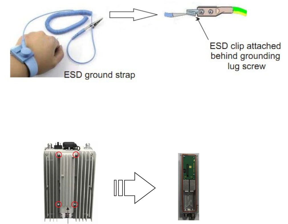
To install an SFP transceiver module into the 9764 CMCO SFP port:
...................................................................................................................................................................................................
1Firstly, carry out the following to attach the ESD wrist strap:
•Attach the ESD strap over your wrist so that is in contact with your bare skin.
•Momentarily touch the ESD clip onto a bare (unpainted) metal spot so that any built
up static charge is dissipated.
•Attach the ESD clip to the MCO ground lug screw (the ground lug screw can be
unscrewed slightly for easier ESD clip attachment).
...................................................................................................................................................................................................
2Remove the four screws holding the backhaul module onto the back of the 9764 CMCO
and turn the module through 180° to access the SFP ports.
Backhaul
module
Installation
Pre-installation cabling
Ethernet cabling - fiber optic
....................................................................................................................................................................................................................................
....................................................................................................................................................................................................................................
4-4 Alcatel-Lucent – Internal
Proprietary – Use pursuant to Company instruction
9764 CMCO B41 2x6W
3MN-02026-0002-RJZZA
Issue 0.01 April 2015
P
RELIMINARY
P
RELIMINARY
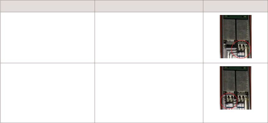
...................................................................................................................................................................................................
3Remove the SFP transceiver module from its protective packaging. Check the label on the
SFP transceiver module body to verify that you have the correct type and model for your
network.
Important! Do not remove the SFP transceiver module dust plugs until directed to do
so later in the procedure.
...................................................................................................................................................................................................
4Insert SFP transceiver modules into SFP ports.
If... Then... View
You are connecting a single
cable from the backhaul system.
Align the backhaul optical SFP
transceiver module with the SFP port
labelled “BH 1” and insert the
module into the socket until you feel
the connector latch into place.
You are connecting a daisy
chain cable in addition to the
cable from the backhaul system.
Align the daisy chain optical SFP
transceiver module with the SFP port
labelled “BH 2” and insert the
module into the socket until you feel
the connector latch into place.
Attention: If the SFP module resists as you insert it, do not force it. Remove the
module, turn it over, and try reinserting.
...................................................................................................................................................................................................
5Push up and latch the SFP module locking bar into position to secure the SFP transceiver
module(s) into the port.
...................................................................................................................................................................................................
6To check that each SFP transceiver module is seated and latched properly, grasp the SFP
module and try to remove it without releasing the latch.
If the SFP module cannot be removed, it is installed and seated properly. If the SFP
module can be removed, reinsert it until the module is latched securely into the socket.
Installation
Pre-installation cabling
Ethernet cabling - fiber optic
....................................................................................................................................................................................................................................
....................................................................................................................................................................................................................................
9764 CMCO B41 2x6W
3MN-02026-0002-RJZZA
Issue 0.01 April 2015
Alcatel-Lucent – Internal
Proprietary – Use pursuant to Company instruction 4-5
P
RELIMINARY
P
RELIMINARY
END OF STEPS
...................................................................................................................................................................................................
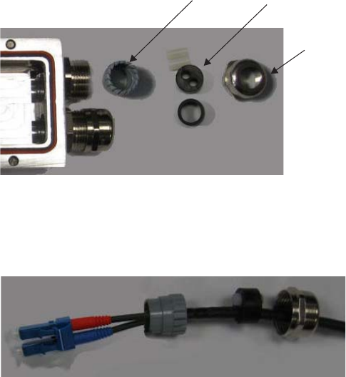
Connect the Ethernet cable
To connect the Ethernet cable(s) to the 9764 CMCO, perform the following steps:
...................................................................................................................................................................................................
1Ensure that the Ethernet cable coming from the backhaul system to the 9764 CMCO is
correctly routed. If daisy chaining to a second 9764 CMCO, ensure that the daisy chain
Ethernet cable is correctly routed to this 9764 CMCO.
...................................................................................................................................................................................................
2Unscrew and remove the rounded compression nut from the cable gland located on the
bottom of the bottom of the backhaul module.
In the following order place the rounded compression nut, the cable seal and the strain
relief onto the Ethernet cable, as shown:
...................................................................................................................................................................................................
3Feed the Ethernet cable through the backhaul module gland opening and replace the cable
clamp onto the optical cable.
Remove dust plugs from the optical cable connectors and the SFP transceiver module and
immediately insert the cable connectors into the SFP transceiver in the port labelled “BH
1”.
Gland
compression nut
Cable seal
Cable strain
relief
Installation
Pre-installation cabling
Ethernet cabling - fiber optic
....................................................................................................................................................................................................................................
....................................................................................................................................................................................................................................
4-6 Alcatel-Lucent – Internal
Proprietary – Use pursuant to Company instruction
9764 CMCO B41 2x6W
3MN-02026-0002-RJZZA
Issue 0.01 April 2015
P
RELIMINARY
P
RELIMINARY
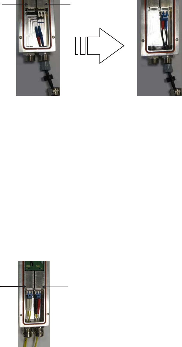
...................................................................................................................................................................................................
4Loosely insert the gland assembly into the gland housing.
Note: The gland assembly with cable may need to be turned slightly in order to fully
slide into the gland housing before the compression nut can be screwed on.
...................................................................................................................................................................................................
5Screw the rounded compression nut back onto the main body of the gland. Use an
adjustable or open-end wrench to tighten the compression nut.
Important! Alcatel-Lucent recommends that the compression nut is torqued to 2.5 N
m (1.8 lb.ft) in order to create a watertight seal and avoid a potential loose connection.
...................................................................................................................................................................................................
6If you are daisy chaining two 9764 CMCOs feed optical Ethernet cable through the
second bachkaul module cable gland and insert the daisy chain Ethernet cable connector
into the SFP transceiver in the port labelled “BH 2”.
BH1 port
BH2 port
BH1 port
BH2 port
Installation
Pre-installation cabling
Ethernet cabling - fiber optic
....................................................................................................................................................................................................................................
....................................................................................................................................................................................................................................
9764 CMCO B41 2x6W
3MN-02026-0002-RJZZA
Issue 0.01 April 2015
Alcatel-Lucent – Internal
Proprietary – Use pursuant to Company instruction 4-7
P
RELIMINARY
P
RELIMINARY
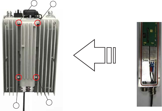
...................................................................................................................................................................................................
7Reattach the backhaul module to the 9764 CMCO using the four retention screws.
Important! Ensure the backhaul module gasket is seated correctly in the groove on
the underside of the backhaul module. Tighten the four retention screws in the
sequence shown. Recommended torque, 2.0 N.m (17.7 lb.in).
...................................................................................................................................................................................................
8Finally, secure the Ethernet cable(s) to the wall or pole.
Important! When securing cables ensure the following to avoid cable damage:
•Secure cables with cable clips. Use additional clips wherever necessary for
neatness.
•All cables should be run parallel with no twisting or tangled cables.
•Avoid excessive tension on the cables.
4
1
3
2
Installation
Pre-installation cabling
Ethernet cabling - fiber optic
....................................................................................................................................................................................................................................
....................................................................................................................................................................................................................................
4-8 Alcatel-Lucent – Internal
Proprietary – Use pursuant to Company instruction
9764 CMCO B41 2x6W
3MN-02026-0002-RJZZA
Issue 0.01 April 2015
P
RELIMINARY
P
RELIMINARY
END OF STEPS
...................................................................................................................................................................................................
Ethernet cabling - electrical
Purpose
This topic describes the procedures to be followed when connecting an electrical Ethernet
cable to the 9764 CMCO. The 9764 CMCO may either be in a single configuration, or
daisy chained to a second 9764 CMCO.
Cabling ancillary items
The following backhaul cabling related ancillary items can be ordered from
Alcatel-Lucent:
•10/100/1000Base-T electrical transceiver. See “SFP modules” (p. 2-16).
•Electrical Ethernet cable with RJ45 connector to electrical SFP module. See “Ethernet
cable - Electrical” (p. 2-17).
Before you begin
Before you begin the following should be noted:
•Equipment cabling should only be carried out by suitably trained or qualified
personnel and must comply with local and national electrical codes.
•As a prerequisite, backhaul cable has been routed from the backhaul system to the
9764 CMCO.
•One SFP port may be cabled for backhaul to the network while the other SFP port
may be cabled for daisy chaining to another 9764 CMCO.
•If the backhaul module is to be cabled after the 9764 CMCO is mounted onto a
surface then, in order to gain access to the backhaul module, the 9764 CMCO must
firstly be placed in the “service position”. Once the cabling is complete the 9764
CMCO should then be moved back to it's “ normal position” . See, Appendix A,
“9764 CMCO service position”
Install SFP transceiver module
Before the Ethernet cable can be connected to the 9764 CMCO, the SFP port(s) must be
equipped with the appropriate SFP transceiver (either 1000Base-X GigE optical
transceiver or 10/100/1000Base-T electrical transceiver), according to the network
specifications.
Installation
Pre-installation cabling
Ethernet cabling - electrical
....................................................................................................................................................................................................................................
....................................................................................................................................................................................................................................
9764 CMCO B41 2x6W
3MN-02026-0002-RJZZA
Issue 0.01 April 2015
Alcatel-Lucent – Internal
Proprietary – Use pursuant to Company instruction 4-9
P
RELIMINARY
P
RELIMINARY
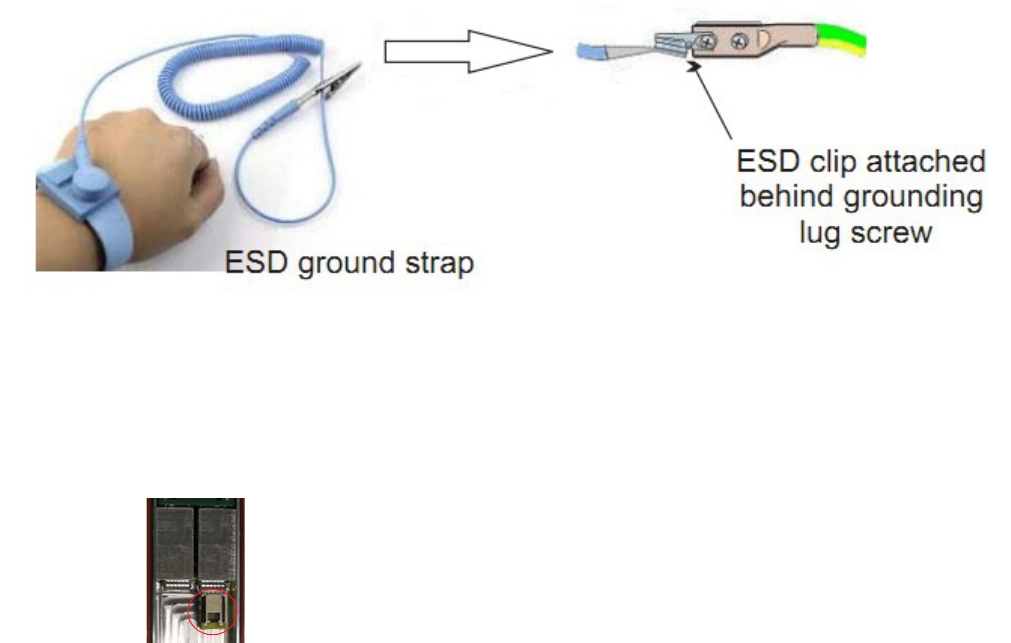
To install an SFP transceiver module into the 9764 CMCO SFP port:
...................................................................................................................................................................................................
1Firstly, carry out the following to attach the ESD wrist strap:
•Attach the ESD strap over your wrist so that is in contact with your bare skin.
•Momentarily touch the ESD clip onto a bare (unpainted) metal spot so that any built
up static charge is dissipated.
•Attach the ESD clip to the MCO ground lug screw (the ground lug screw can be
unscrewed slightly for easier ESD clip attachment).
...................................................................................................................................................................................................
2Remove the four screws holding the backhaul module onto the back of the 9764 CMCO
and turn the module through 180° to access the SFP ports.
...................................................................................................................................................................................................
3Remove the SFP transceiver module from its protective packaging. Check the label on the
SFP transceiver module body to verify that you have the correct type and model for your
network.
Important! Do not remove the SFP transceiver module dust plugs until directed to do
so later in the procedure.
Installation
Pre-installation cabling
Ethernet cabling - electrical
....................................................................................................................................................................................................................................
....................................................................................................................................................................................................................................
4-10 Alcatel-Lucent – Internal
Proprietary – Use pursuant to Company instruction
9764 CMCO B41 2x6W
3MN-02026-0002-RJZZA
Issue 0.01 April 2015
P
RELIMINARY
P
RELIMINARY
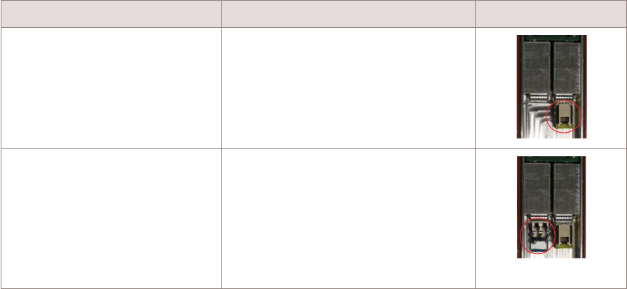
...................................................................................................................................................................................................
4Insert SFP transceiver modules into SFP ports.
If... Then... View
You are connecting a single
cable from the backhaul system.
Align the backhaul electrical SFP
transceiver module with the SFP port
labelled “BH 1” and insert the
module into the socket until you feel
the connector latch into place.
You are connecting a daisy
chain cable in addition to the
cable from the backhaul system.
Align the daisy chain optical SFP
transceiver module with the SFP port
labelled “BH 2” and insert the
module into the socket until you feel
the connector latch into place.
Attention: If the SFP module resists as you insert it, do not force it. Remove the
module, turn it over, and try reinserting.
...................................................................................................................................................................................................
5Push up and latch the SFP module locking bar into position to secure the SFP transceiver
module(s) into the port.
...................................................................................................................................................................................................
6To check that each SFP transceiver module is seated and latched properly, grasp the SFP
module and try to remove it without releasing the latch.
If the SFP module cannot be removed, it is installed and seated properly. If the SFP
module can be removed, reinsert it until the module is latched securely into the socket.
Connect the Ethernet cable
Follow these step to connect the electrical Ethernet backhaul cable to the SFP module in
the 9764 CMCO or the optional internal surge arrestor module (if installed).
...................................................................................................................................................................................................
1Obtain, from the packaging, the Alcatel-Lucent electrical Ethernet cable. The RJ45
connector without connector cover should be used at the 9764 CMCO side.
Installation
Pre-installation cabling
Ethernet cabling - electrical
....................................................................................................................................................................................................................................
....................................................................................................................................................................................................................................
9764 CMCO B41 2x6W
3MN-02026-0002-RJZZA
Issue 0.01 April 2015
Alcatel-Lucent – Internal
Proprietary – Use pursuant to Company instruction 4-11
P
RELIMINARY
P
RELIMINARY
END OF STEPS
...................................................................................................................................................................................................
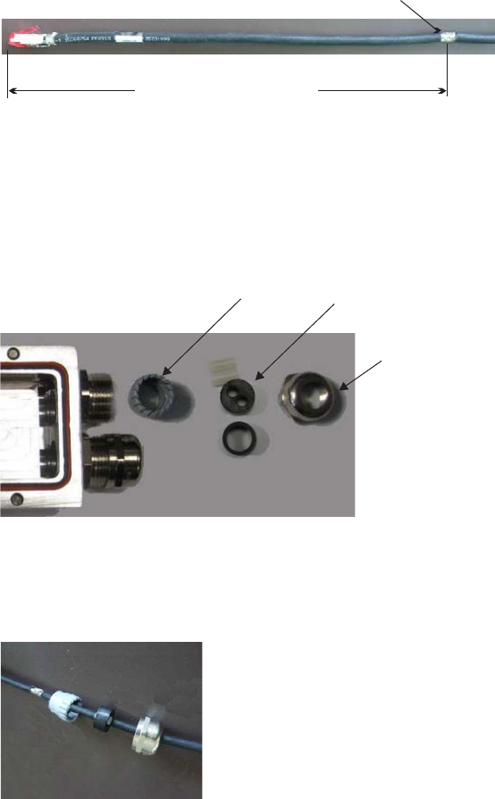
Note: If an external surge arrestor is installed then use a short cable from the surge
arrestor to the 9764 CMCO.
...................................................................................................................................................................................................
2For increased cable connection within the cable gland, expose a section of screen braid
(approximately 10 mm) by cutting through the cable jacket. The exposed section should
measured from the leading edge of the RJ45 connector to the center of the exposed area.
...................................................................................................................................................................................................
3Unscrew and remove the rounded compression nut from the cable gland located on the
bottom of the bottom of the backhaul module.
In the following order place the rounded compression nut, the cable seal and the strain
relief onto the Ethernet cable, as shown:
92
3.5 1
cm (+/- mm)
inches (+/- 0. inches)
Exposed screen braid
approx. 10 mm (0.4 inches)
Gland
compression nut
Cable seal
Cable strain
relief
Installation
Pre-installation cabling
Ethernet cabling - electrical
....................................................................................................................................................................................................................................
....................................................................................................................................................................................................................................
4-12 Alcatel-Lucent – Internal
Proprietary – Use pursuant to Company instruction
9764 CMCO B41 2x6W
3MN-02026-0002-RJZZA
Issue 0.01 April 2015
P
RELIMINARY
P
RELIMINARY
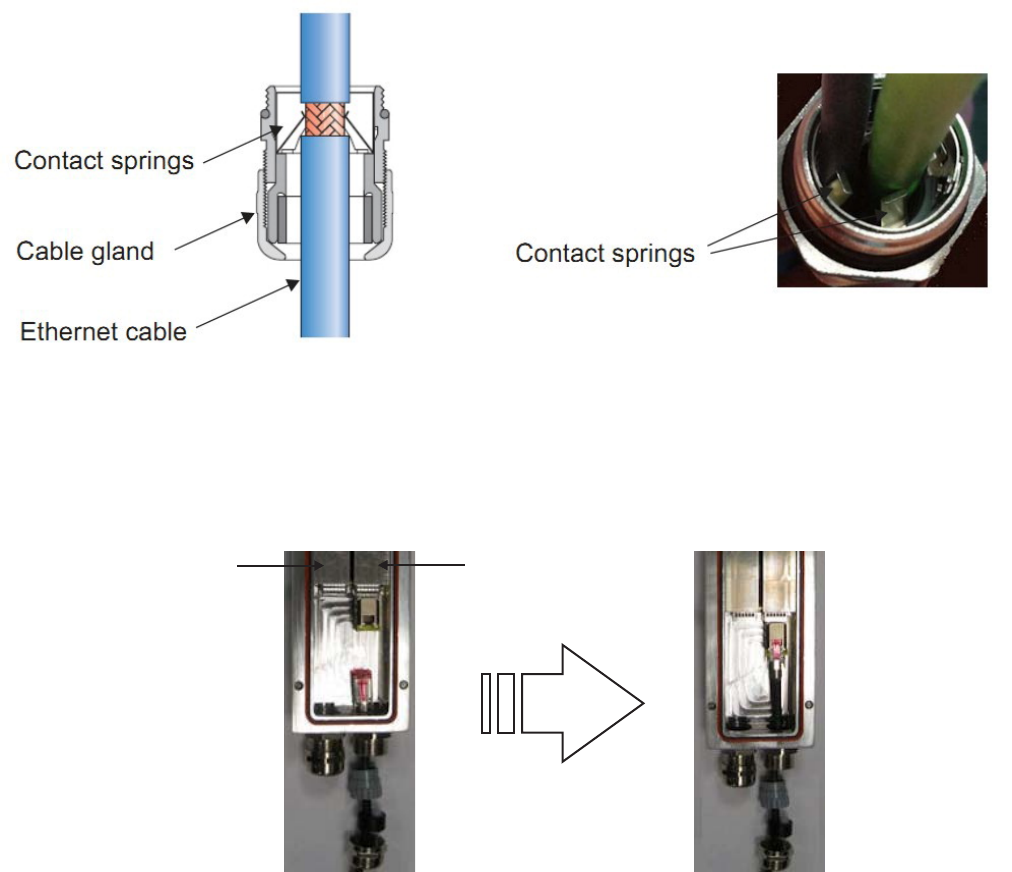
...................................................................................................................................................................................................
4Pull the cable through the gland assembly parts until a connection is made between the
exposed cable screen braid and the gland contact springs.
...................................................................................................................................................................................................
5Feed the Ethernet cable through the gland opening on the backhaul module and insert the
Ethernet cable connector into the SFP transceiver in the port labelled “BH 1”.
...................................................................................................................................................................................................
6Loosely insert the gland assembly into the gland housing.
Note: The gland assembly with cable may need to be turned slightly in order to fully
slide into the gland housing before the compression nut can be screwed on.
BH1 port
BH2 port
Installation
Pre-installation cabling
Ethernet cabling - electrical
....................................................................................................................................................................................................................................
....................................................................................................................................................................................................................................
9764 CMCO B41 2x6W
3MN-02026-0002-RJZZA
Issue 0.01 April 2015
Alcatel-Lucent – Internal
Proprietary – Use pursuant to Company instruction 4-13
P
RELIMINARY
P
RELIMINARY
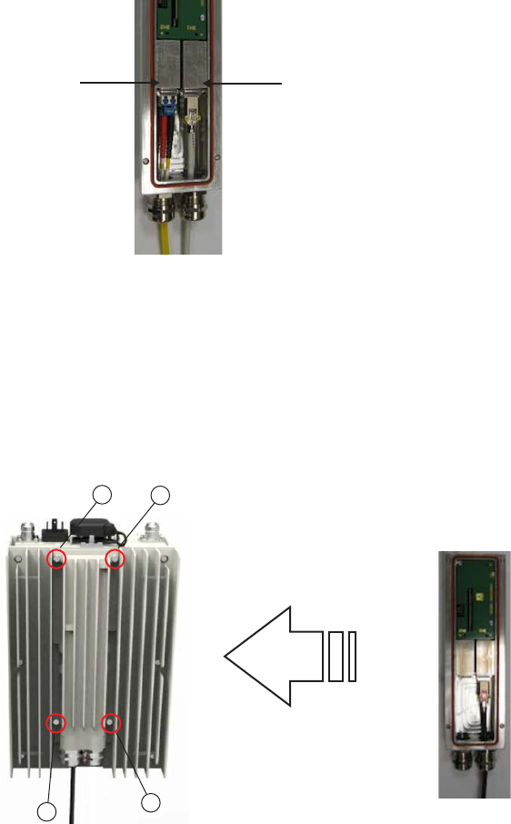
...................................................................................................................................................................................................
7Screw the rounded compression nut back onto the main body of the gland. Use an
adjustable or open-end wrench to tighten the compression nut.
Important! It is recommended that the compression nut is torqued to 2.5 N.m (22.1
lb.in) in order to create a watertight seal and avoid a potential loose connection.
...................................................................................................................................................................................................
8If you are daisy chaining two 9764 CMCO, feed optical Ethernet cable through the
second backhaul module cable gland and insert the daisy chain Ethernet cable connector
into the SFP transceiver in the port labelled “BH 2”.
...................................................................................................................................................................................................
9Reattach the backhaul module to the 9764 CMCO using the four retention screws.
Important! Ensure the backhaul module gasket is seated correctly in the groove on
the underside of the backhaul module. Tighten the four retention screws in the
sequence shown. Recommended torque, 2.0 N.m (17.7 lb.in).
BH1 port
BH2 port
4
1
3
2
Installation
Pre-installation cabling
Ethernet cabling - electrical
....................................................................................................................................................................................................................................
....................................................................................................................................................................................................................................
4-14 Alcatel-Lucent – Internal
Proprietary – Use pursuant to Company instruction
9764 CMCO B41 2x6W
3MN-02026-0002-RJZZA
Issue 0.01 April 2015
P
RELIMINARY
P
RELIMINARY
...................................................................................................................................................................................................
10 Finally, secure the Ethernet cable to the wall or pole.
Important! When securing cables ensure the following to avoid cable damage:
•Secure cables with tie wraps. Use additional tie wraps wherever necessary for
neatness
•All cables should be run parallel with no twisting or tangled cables
•Avoid excessive tension on the cable.
Cable the optional external surge arrestor
Follow these steps to connect the Ethernet cables to the external surge arrestor.
...................................................................................................................................................................................................
1On the surge arrestor, unscrew the lower weatherized strain relief connector and locking
nut from the surge arrestor.
...................................................................................................................................................................................................
2Carefully feed the end of Ethernet cable coming from the Customer Network Interface
Device through the unscrewed lower strain relief connector.
...................................................................................................................................................................................................
3Plug the Ethernet cable RJ45 connector into the lower connector on the arrestor. Screw
the weatherized strain relief connector back onto the arrestor and tighten.
...................................................................................................................................................................................................
4At the top of the arrestor, unscrew the upper weatherized strain relief connector from the
surge arrestor.
...................................................................................................................................................................................................
5Carefully feed the end of Ethernet cable coming from the 9764 CMCO through the upper
strain relief connector.
...................................................................................................................................................................................................
6Plug the Ethernet cable RJ45 connector into the upper connector on the arrestor. Screw
the weatherized strain relief connector back onto the arrestor and tighten.
...................................................................................................................................................................................................
7Finally, secure the Ethernet cable to the wall/pole.
Installation
Pre-installation cabling
Ethernet cabling - electrical
....................................................................................................................................................................................................................................
....................................................................................................................................................................................................................................
9764 CMCO B41 2x6W
3MN-02026-0002-RJZZA
Issue 0.01 April 2015
Alcatel-Lucent – Internal
Proprietary – Use pursuant to Company instruction 4-15
P
RELIMINARY
P
RELIMINARY
END OF STEPS
...................................................................................................................................................................................................
Important! When securing cables ensure the following to avoid cable damage:
•Secure cables with tie wraps. Use additional tie wraps wherever necessary for
neatness.
•All cables should be run parallel with no twisting or tangled cables.
•Avoid excessive tension on the cable.
Installation
Pre-installation cabling
Ethernet cabling - electrical
....................................................................................................................................................................................................................................
....................................................................................................................................................................................................................................
4-16 Alcatel-Lucent – Internal
Proprietary – Use pursuant to Company instruction
9764 CMCO B41 2x6W
3MN-02026-0002-RJZZA
Issue 0.01 April 2015
P
RELIMINARY
P
RELIMINARY
END OF STEPS
...................................................................................................................................................................................................

Installation
Overview
Purpose
This section provides the installation instructions for mounting the 9764 CMCO onto
either a pole or wall with or without the optional tilt mechanism.
Contents
Pole mount the 9764 CMCO 4-18
Pole mount the 9764 CMCO using optional tilt brackets 4-24
Wall mount the 9764 CMCO 4-32
Wall mount the 9764 CMCO using optional tilt brackets 4-38
Installation
Installation
Overview
....................................................................................................................................................................................................................................
....................................................................................................................................................................................................................................
9764 CMCO B41 2x6W
3MN-02026-0002-RJZZA
Issue 0.01 April 2015
Alcatel-Lucent – Internal
Proprietary – Use pursuant to Company instruction 4-17
P
RELIMINARY
P
RELIMINARY
Pole mount the 9764 CMCO
Purpose
This topic describes the procedures to be followed when installing the 9764 CMCO onto
a pole using pole bands.
Prerequisites
A site survey has been conducted and a location for the device has been selected that is
both central to the public space and elevated in order to maximize coverage. Before
installation begins you should ensure the following are in place:
•Ensure adequate clearance is provided for service access.
•Ground cable has been routed and the site grounding system is in place.
•Backhaul cable has been routed and is in place.
•Any site specific fixing materials are available (for example, bolts, washers and wall
plug materials).
Attention: The 9764 CMCO must be mounted with the appropriate mounting
hardware suitable for the various supporting structures, building materials and
construction methods. Following a site survey, it is the responsibility of the customer
to ensure that:
•The installation support structure is adequate and compliant with ICC IBC (2012):
International Building Code, and all other national and local codes.
•The appropriate mounting hardware and any necessary recommended supporting
anchor fixings are used.
Mounting requirements and materials
The 9764 CMCO can be easily mounted onto a wooden or metal pole. Refer to the
following for the installation kits, anchor materials and tools for the installation type:
•For pole mount refer to, “Pole mount installation requirements” (p. 3-5).
•For a list of standard tools that may be required to support the installation, see “Tools
required for installation” (p. 3-3).
Before you begin
Record the 9764 CMCO 18 digit serial number before mounting onto a pole.
Installation
Installation
Pole mount the 9764 CMCO
....................................................................................................................................................................................................................................
....................................................................................................................................................................................................................................
4-18 Alcatel-Lucent – Internal
Proprietary – Use pursuant to Company instruction
9764 CMCO B41 2x6W
3MN-02026-0002-RJZZA
Issue 0.01 April 2015
P
RELIMINARY
P
RELIMINARY
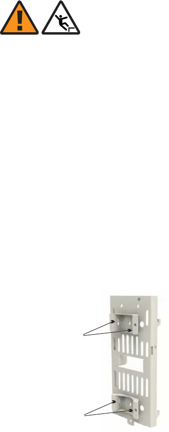
Pole mount the 9764 CMCO
WARNING
Fall hazard
Falls can occur when working at heights resulting in serious personal injury or death.
To prevent a fall when working at heights (ladder, scaffold, manlift, roof etc.) follow safe
work practices and wear appropriate fall protection equipment.
Perform the following procedure to pole mount the 9764 CMCO using standard pole
bands.
...................................................................................................................................................................................................
1Refer to the equipment orientation plan and, at the selected installation point on the pole,
mark the upper and lower position of the pole bands. Using digital compass determine the
planned left/right orientation of the 9764 CMCO mounting bracket around the pole and
mark the center line of the left/right orientation on the pole.
...................................................................................................................................................................................................
2Using the supplied stainless steel pole bands insert and thread the open band ends into the
upper and lower slots on the reverse side of the mounting bracket.
...................................................................................................................................................................................................
3At the marked installation point on the pole place the bands around the pole at the
determined height. Carry out any required adjustment of the mounting bracket around the
pole so that it is pointing in the desired direction.
Upper banding slots
Lower banding slots
Installation
Installation
Pole mount the 9764 CMCO
....................................................................................................................................................................................................................................
....................................................................................................................................................................................................................................
9764 CMCO B41 2x6W
3MN-02026-0002-RJZZA
Issue 0.01 April 2015
Alcatel-Lucent – Internal
Proprietary – Use pursuant to Company instruction 4-19
P
RELIMINARY
P
RELIMINARY
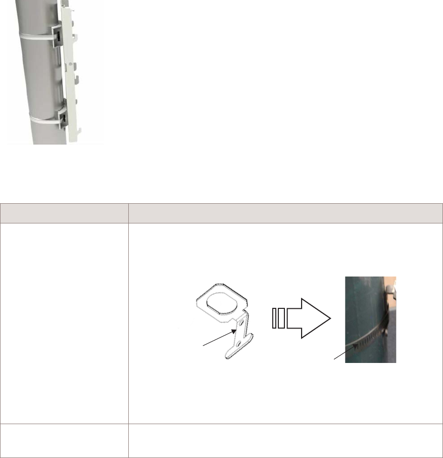
...................................................................................................................................................................................................
4
If... Then...
A surge arrestor1is to be
mounted on the pole
Obtain the surge arrestor bracket from the surge arrestor kit and
position the bracket lug behind either the upper or lower pole band.
Surge arrestor
bracket
Banding lug Pole band
Once the surge arrestor bracket is in the desired position, proceed
with the next step.
A surge arrestor is not
used
Proceed with the next step.
Notes:
1. Although optional, Alcatel-Lucent strongly recommends for outdoor deployments, that when
the backhaul connection is configured for electrical Ethernet (GBE 10/100/1000BaseT) a
surge arrestor is installed, as the electrical SFP does not provide surge protection.
...................................................................................................................................................................................................
5Once the mounting bracket is in the correct position and orientation tighten and secure the
bands around the pole. Check the banding is secure, there is no movement of the bracket
around the pole and that the banding stubs (cut ends) are flattened down with a hammer.
Note: Refer to BAND-IT®C00169 Hand Tool Operation Instructions, PO5886.
Installation
Installation
Pole mount the 9764 CMCO
....................................................................................................................................................................................................................................
....................................................................................................................................................................................................................................
4-20 Alcatel-Lucent – Internal
Proprietary – Use pursuant to Company instruction
9764 CMCO B41 2x6W
3MN-02026-0002-RJZZA
Issue 0.01 April 2015
P
RELIMINARY
P
RELIMINARY

...................................................................................................................................................................................................
6To attach the 9764 CMCO to the mounting bracket open the mounting frame lever by
pulling the lever outwards.
...................................................................................................................................................................................................
7Align the mounting points on the reverse side of the 9764 CMCO with the mounting lugs
on the bracket. Attach the 9764 CMCO to the bracket by sliding the 9764 CMCO
forwards and downwards onto the bracket mounting lugs.
...................................................................................................................................................................................................
8Secure the 9764 CMCO onto the mounting frame by tightening the lever retaining screw.
Installation
Installation
Pole mount the 9764 CMCO
....................................................................................................................................................................................................................................
....................................................................................................................................................................................................................................
9764 CMCO B41 2x6W
3MN-02026-0002-RJZZA
Issue 0.01 April 2015
Alcatel-Lucent – Internal
Proprietary – Use pursuant to Company instruction 4-21
P
RELIMINARY
P
RELIMINARY
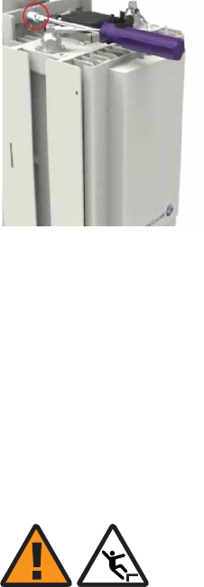
...................................................................................................................................................................................................
9Finally, check the 9764 CMCO is correctly locked into position and there is no movement
of the module on the mounting frame.
Mount surge arrestor (optional)
WARNING
Fall hazard
Falls can occur when working at heights resulting in serious personal injury or death.
To prevent a fall when working at heights (ladder, scaffold, manlift, roof etc.) follow safe
work practices and wear appropriate fall protection equipment.
Although optional, Alcatel-Lucent strongly recommends for outdoor deployments, that
when the backhaul connection is configured for electrical Ethernet (GBE
10/100/1000BaseT) a surge arrestor is installed, as the electrical SFP does not provide
surge protection.
Follow these steps to mount the optional external surge arrestor onto the surge arrestor
bracket where the surge arrestor bracket has already been banded to a pole.
...................................................................................................................................................................................................
1On the surge arrestor, unscrew the lower weatherized strain relief connector and locking
nut from the surge arrestor.
...................................................................................................................................................................................................
2Site the surge arrestor onto the bracket so that the lower threaded Ethernet connection
point is positioned through the arrestor mounting hole.
Installation
Installation
Pole mount the 9764 CMCO
....................................................................................................................................................................................................................................
....................................................................................................................................................................................................................................
4-22 Alcatel-Lucent – Internal
Proprietary – Use pursuant to Company instruction
9764 CMCO B41 2x6W
3MN-02026-0002-RJZZA
Issue 0.01 April 2015
P
RELIMINARY
P
RELIMINARY
END OF STEPS
...................................................................................................................................................................................................
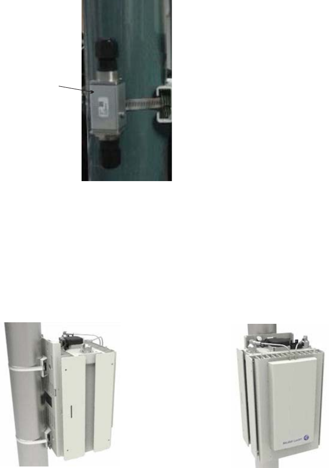
...................................................................................................................................................................................................
3Screw the arrestor locking nut back onto the arrestor and tighten so that the arrestor is
securely attached to the bracket.
Standard pole mount example
The following figure depicts a 9764 CMCO standard pole mount using pole bands.
How to continue
After mounting the 9764 CMCO onto a pole the cables need to be connected. Continue
with the Chapter 5, “Cabling” chapter.
External
surge arrestor
Installation
Installation
Pole mount the 9764 CMCO
....................................................................................................................................................................................................................................
....................................................................................................................................................................................................................................
9764 CMCO B41 2x6W
3MN-02026-0002-RJZZA
Issue 0.01 April 2015
Alcatel-Lucent – Internal
Proprietary – Use pursuant to Company instruction 4-23
P
RELIMINARY
P
RELIMINARY
END OF STEPS
...................................................................................................................................................................................................
Pole mount the 9764 CMCO using optional tilt brackets
Purpose
This topic describes the procedures to be followed when installing the 9764 CMCO onto
a pole using optional tilt brackets.
Prerequisites
A site survey has been conducted and a location for the device has been selected that is
both central to the public space and elevated in order to maximize coverage. Before
installation begins you should ensure the following are in place:
•Ensure adequate clearance is provided for service access.
•Ground cable has been routed and the site grounding system is in place.
•Backhaul cable has been routed and is in place.
•Any site specific fixing materials are available (for example, bolts, washers and wall
plug materials).
Attention: The 9764 CMCO must be mounted with the appropriate mounting
hardware suitable for the various supporting structures, building materials and
construction methods. Following a site survey, it is the responsibility of the customer
to ensure that:
•The installation support structure is adequate and compliant with ICC IBC (2012):
International Building Code, and all other national and local codes.
•The appropriate mounting hardware and any necessary recommended supporting
anchor fixings are used.
Mounting requirements and materials
The 9764 CMCO can be easily mounted onto a wooden or metal pole. Refer to the
following for the installation kits, anchor materials and tools for the installation type:
•For pole mount, refer to “Pole mount installation requirements” (p. 3-5).
•For a list of standard tools that may be required to support the installation, see “Tools
required for installation” (p. 3-3).
Before you begin
Record the 9764 CMCO 18 digit serial number before mounting onto a pole.
Installation
Installation
Pole mount the 9764 CMCO using optional tilt brackets
....................................................................................................................................................................................................................................
....................................................................................................................................................................................................................................
4-24 Alcatel-Lucent – Internal
Proprietary – Use pursuant to Company instruction
9764 CMCO B41 2x6W
3MN-02026-0002-RJZZA
Issue 0.01 April 2015
P
RELIMINARY
P
RELIMINARY
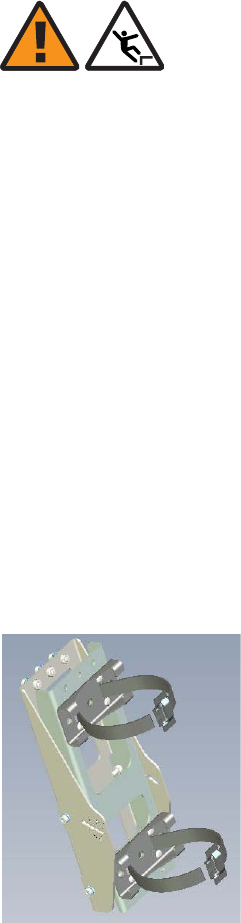
Attach pole brackets onto a pole
WARNING
Fall hazard
Falls can occur when working at heights resulting in serious personal injury or death.
To prevent a fall when working at heights (ladder, scaffold, manlift, roof etc.) follow safe
work practices and wear appropriate fall protection equipment.
Perform the following procedure attach the tilt bracket onto a pole.
...................................................................................................................................................................................................
1Refer to the equipment orientation plan and, at the selected installation point on the pole,
mark the upper and lower position of the pole bands. Using digital compass determine the
planned horizontal (left/right) orientation of the 9764 CMCO around the pole and mark
the center line of the left/right orientation on the pole.
...................................................................................................................................................................................................
2Using the supplied stainless steel pole bands insert and thread the open end of one band
into the upper two slots on the tilt bracket.
Taking the other steel band insert and thread the open end into the lower two slots on the
tilt bracket.
Installation
Installation
Pole mount the 9764 CMCO using optional tilt brackets
....................................................................................................................................................................................................................................
....................................................................................................................................................................................................................................
9764 CMCO B41 2x6W
3MN-02026-0002-RJZZA
Issue 0.01 April 2015
Alcatel-Lucent – Internal
Proprietary – Use pursuant to Company instruction 4-25
P
RELIMINARY
P
RELIMINARY
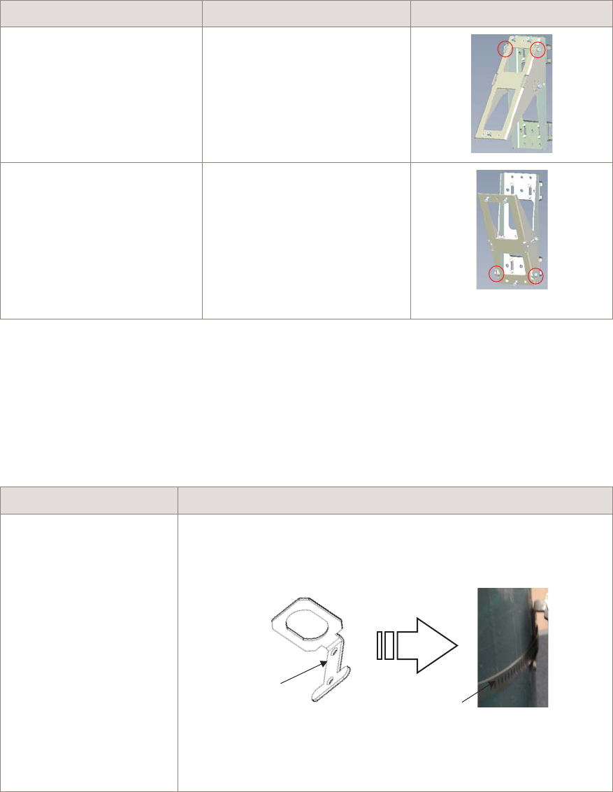
...................................................................................................................................................................................................
3Depending on the required vertical tilt orientation ensure the bracket is positioned the
correct way up before placing on the pole:
If... Then... View...
upward vertical tilt is
required
the tilt bracket must be
positioned with the pivot point
at the top
downward vertical tilt is
required
the tilt bracket must be
positioned with the pivot point
at the bottom
...................................................................................................................................................................................................
4At the marked installation point on the pole wrap the upper and lower pole bands around
the pole at the determined height. Carry out any required adjustment of the tilt bracket
around the pole so that it is pointing in the desired direction.
...................................................................................................................................................................................................
5
If... Then...
A surge arrestor1is to be
mounted on the pole
Obtain the surge arrestor bracket from the surge arrestor kit and
position the bracket lug behind either the upper or lower pole band.
Surge arrestor
bracket
Banding lug Pole band
Once the surge arrestor bracket is in the desired position, proceed
with the next step.
Installation
Installation
Pole mount the 9764 CMCO using optional tilt brackets
....................................................................................................................................................................................................................................
....................................................................................................................................................................................................................................
4-26 Alcatel-Lucent – Internal
Proprietary – Use pursuant to Company instruction
9764 CMCO B41 2x6W
3MN-02026-0002-RJZZA
Issue 0.01 April 2015
P
RELIMINARY
P
RELIMINARY
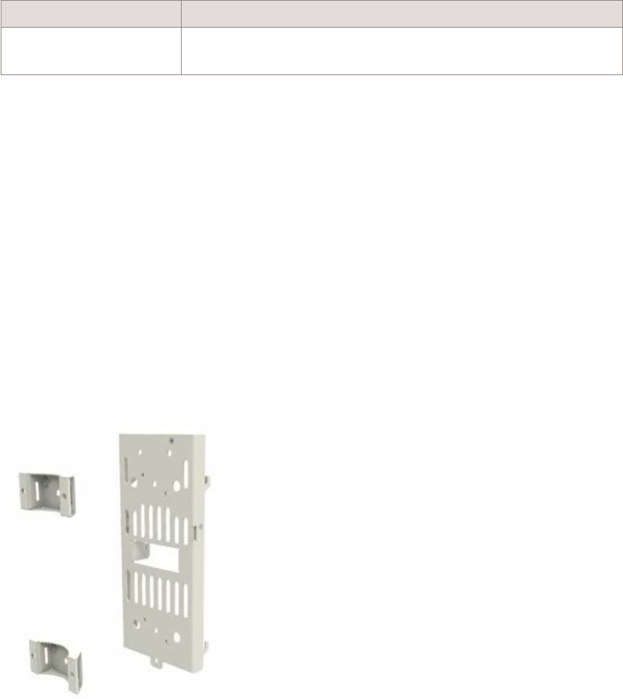
If... Then...
A surge arrestor is not
used
Proceed with the next step.
Notes:
1. Although optional, Alcatel-Lucent strongly recommends for outdoor deployments, that when
the backhaul connection is configured for electrical Ethernet (GBE 10/100/1000BaseT) a
surge arrestor is installed, as the electrical SFP does not provide surge protection.
...................................................................................................................................................................................................
6Once the tilt bracket is in the correct position and orientation tighten and secure the bands
around the pole. Check the banding is secure, there is no movement of the bracket around
the pole and that the banding stubs (cut ends) are flattened down with a hammer.
Note: Refer to BAND-IT®C00169 Hand Tool Operation Instructions, PO5886.
...................................................................................................................................................................................................
7On the reverse side of the 9764 CMCO mounting bracket unscrew the M4 pole grips bolts
and remove the upper and lower pole grips from the bracket.
...................................................................................................................................................................................................
8Unscrew and remove the two upper M6 bolts and the one lower M6 bolt from the tilt
bracket.
Installation
Installation
Pole mount the 9764 CMCO using optional tilt brackets
....................................................................................................................................................................................................................................
....................................................................................................................................................................................................................................
9764 CMCO B41 2x6W
3MN-02026-0002-RJZZA
Issue 0.01 April 2015
Alcatel-Lucent – Internal
Proprietary – Use pursuant to Company instruction 4-27
P
RELIMINARY
P
RELIMINARY
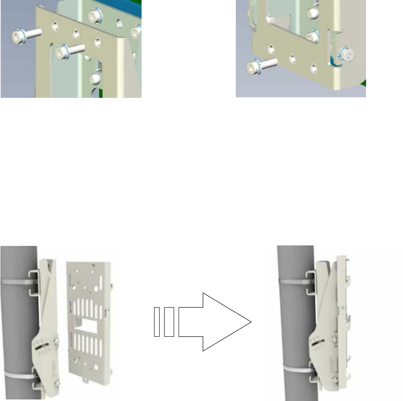
...................................................................................................................................................................................................
9Position the 9764 CMCO mounting bracket against the front of the tilt bracket so that the
two upper bolt holes and the single lower bolt hole on the 9764 CMCO mounting bracket
are aligned with the bolts holes on the tilt bracket. From the 9764 CMCO mounting
bracket side, screw in the two upper M6 bolts and lower M6 bolt to attach the brackets.
...................................................................................................................................................................................................
10 To attach the 9764 CMCO to the mounting bracket open the mounting frame lever by
pulling the lever outwards.
Upper M6 bolts (x2) Lower M6 bolt (x1)
Installation
Installation
Pole mount the 9764 CMCO using optional tilt brackets
....................................................................................................................................................................................................................................
....................................................................................................................................................................................................................................
4-28 Alcatel-Lucent – Internal
Proprietary – Use pursuant to Company instruction
9764 CMCO B41 2x6W
3MN-02026-0002-RJZZA
Issue 0.01 April 2015
P
RELIMINARY
P
RELIMINARY
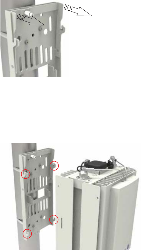
...................................................................................................................................................................................................
11 Align the mounting points on the reverse side of the 9764 CMCO with the mounting lugs
on the bracket. Attach the 9764 CMCO to the bracket by sliding the 9764 CMCO
forwards and downwards onto the bracket mounting lugs.
...................................................................................................................................................................................................
12 Secure the 9764 9764 CMCO onto the mounting frame by tightening the lever retaining
screw.
Installation
Installation
Pole mount the 9764 CMCO using optional tilt brackets
....................................................................................................................................................................................................................................
....................................................................................................................................................................................................................................
9764 CMCO B41 2x6W
3MN-02026-0002-RJZZA
Issue 0.01 April 2015
Alcatel-Lucent – Internal
Proprietary – Use pursuant to Company instruction 4-29
P
RELIMINARY
P
RELIMINARY

...................................................................................................................................................................................................
13 Finally, check the 9764 CMCO is correctly locked into position and there is no movement
of the module on the mounting frame.
Mount surge arrestor (optional)
WARNING
Fall hazard
Falls can occur when working at heights resulting in serious personal injury or death.
To prevent a fall when working at heights (ladder, scaffold, manlift, roof etc.) follow safe
work practices and wear appropriate fall protection equipment.
Although optional, Alcatel-Lucent strongly recommends for outdoor deployments, that
when the backhaul connection is configured for electrical Ethernet (GBE
10/100/1000BaseT) a surge arrestor is installed, as the electrical SFP does not provide
surge protection.
Follow these steps to mount the optional external surge arrestor onto the surge arrestor
bracket where the surge arrestor bracket has already been banded to a pole.
...................................................................................................................................................................................................
1On the surge arrestor, unscrew the lower weatherized strain relief connector and locking
nut from the surge arrestor.
...................................................................................................................................................................................................
2Site the surge arrestor onto the bracket so that the lower threaded Ethernet connection
point is positioned through the arrestor mounting hole.
Installation
Installation
Pole mount the 9764 CMCO using optional tilt brackets
....................................................................................................................................................................................................................................
....................................................................................................................................................................................................................................
4-30 Alcatel-Lucent – Internal
Proprietary – Use pursuant to Company instruction
9764 CMCO B41 2x6W
3MN-02026-0002-RJZZA
Issue 0.01 April 2015
P
RELIMINARY
P
RELIMINARY
END OF STEPS
...................................................................................................................................................................................................
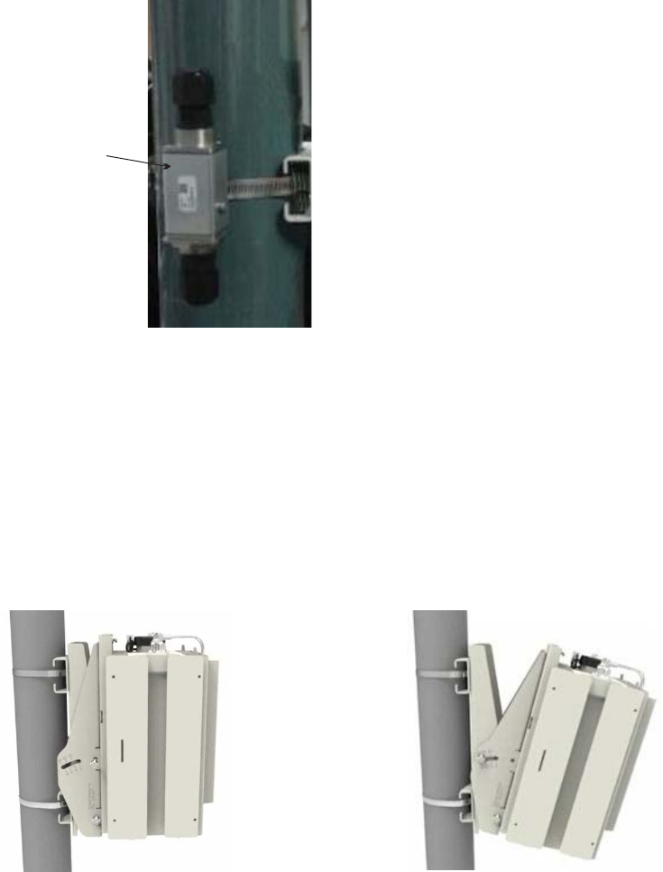
...................................................................................................................................................................................................
3Screw the arrestor locking nut back onto the arrestor and tighten so that the arrestor is
securely attached to the bracket.
Pole mount with tilt example
The following figure depicts a pole mounted 9764 CMCO with tilt installation using pole
bands.
How to continue
After mounting the 9764 CMCO onto a pole the cables need to be connected. Continue
with the Chapter 5, “Cabling” chapter.
External
surge arrestor
Installation
Installation
Pole mount the 9764 CMCO using optional tilt brackets
....................................................................................................................................................................................................................................
....................................................................................................................................................................................................................................
9764 CMCO B41 2x6W
3MN-02026-0002-RJZZA
Issue 0.01 April 2015
Alcatel-Lucent – Internal
Proprietary – Use pursuant to Company instruction 4-31
P
RELIMINARY
P
RELIMINARY
END OF STEPS
...................................................................................................................................................................................................
Wall mount the 9764 CMCO
Purpose
This topic describes the procedures to be followed when installing the 9764 CMCO onto
a wall or solid flat surface
Prerequisites
A site survey has been conducted and a location for the device has been selected that is
both central to the public space and elevated in order to maximize coverage. Before
installation begins you should ensure the following are in place:
•Ensure adequate clearance is provided for service access.
•Ground cable has been routed and the site grounding system is in place.
•Backhaul cable has been routed and is in place.
•Any site specific fixing materials are available (for example, bolts, washers and wall
plug materials).
Attention: The 9764 CMCO must be mounted with the appropriate mounting
hardware suitable for the various supporting structures, building materials and
construction methods. Following a site survey, it is the responsibility of the customer
to ensure that:
•The installation support structure is adequate and compliant with ICC IBC (2012):
International Building Code, and all other national and local codes.
•The appropriate mounting hardware and any necessary recommended supporting
anchor fixings are used.
Mounting requirements and materials
The 9764 CMCO can be easily mounted onto solid concrete or wooden flat surface. Refer
to the following for the installation kits, anchor materials and tools for the installation
type:
•For wall mount, refer to “Wall mount installation requirements” (p. 3-7).
•For a list of standard tools that may be required to support the installation, see “Tools
required for installation” (p. 3-3).
Before you begin
Record the 9764 CMCO 18 digit serial number before mounting onto a wall or flat
surface.
Installation
Installation
Wall mount the 9764 CMCO
....................................................................................................................................................................................................................................
....................................................................................................................................................................................................................................
4-32 Alcatel-Lucent – Internal
Proprietary – Use pursuant to Company instruction
9764 CMCO B41 2x6W
3MN-02026-0002-RJZZA
Issue 0.01 April 2015
P
RELIMINARY
P
RELIMINARY
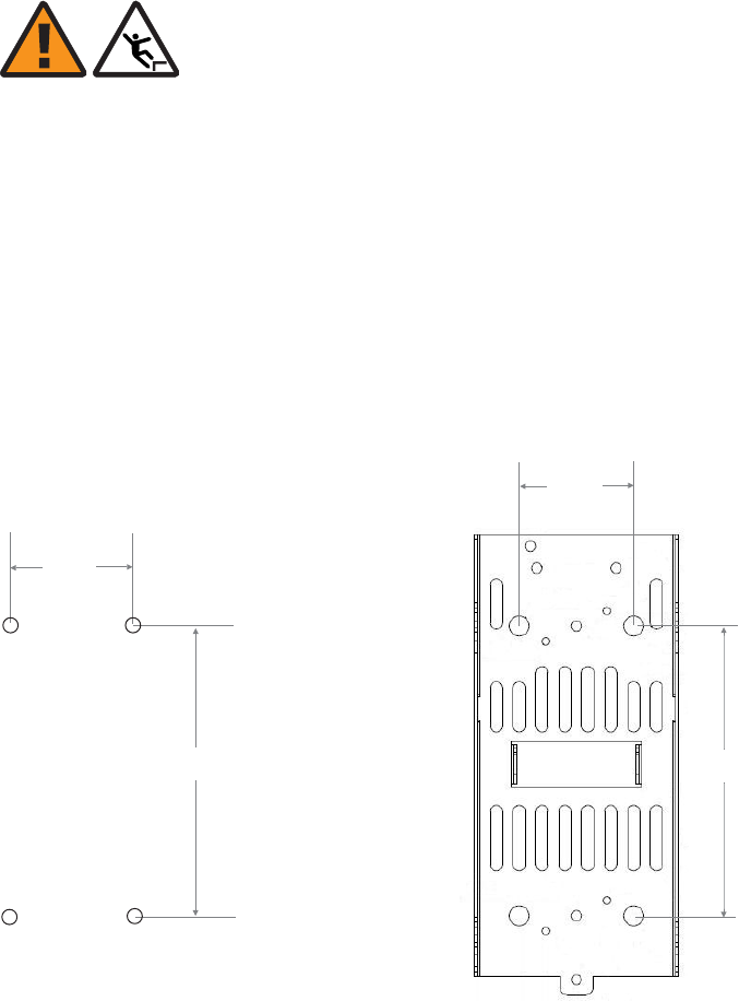
Attach the mounting bracket
WARNING
Fall hazard
Falls can occur when working at heights resulting in serious personal injury or death.
To prevent a fall when working at heights (ladder, scaffold, manlift, roof etc.) follow safe
work practices and wear appropriate fall protection equipment.
Perform the following procedure to attach the 9764 CMCO mounting bracket directly
onto a wall or flat surface.
...................................................................................................................................................................................................
1At the selected installation location, mark the points on the wall for the mounting bracket
anchor holes. See drill hole pattern below to use as a guide:
Tip: The 9764 CMCO mounting bracket can also be used as a template to mark the
points on the wall for the fixing holes.
...................................................................................................................................................................................................
2Check the horizontal marked position of the holes with a spirit level.
75 mm
3.0 inches
190 mm
7.5 inches
75 mm
3.0 inches
190 mm
7.5 inches
Installation
Installation
Wall mount the 9764 CMCO
....................................................................................................................................................................................................................................
....................................................................................................................................................................................................................................
9764 CMCO B41 2x6W
3MN-02026-0002-RJZZA
Issue 0.01 April 2015
Alcatel-Lucent – Internal
Proprietary – Use pursuant to Company instruction 4-33
P
RELIMINARY
P
RELIMINARY
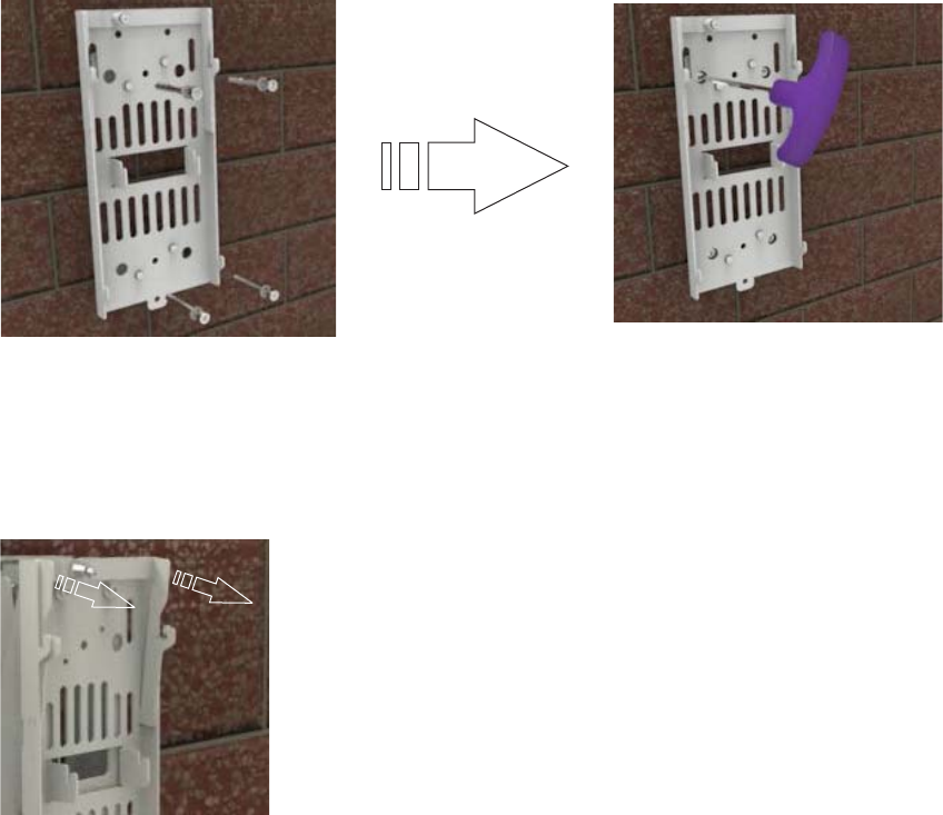
...................................................................................................................................................................................................
3Drill two upper holes and two lower holes at the marked points to the appropriate depth.
Insert screw anchor plugs into the drilled holes and, using a hammer, tap home until the
plugs are flush with the wall.
...................................................................................................................................................................................................
4Align the mounting bracket bolt holes with the drilled wall anchor holes. Screw in the
upper and lower bolts into the wall fixings to the appropriate depth so that the mounting
bracket is securely attached to the wall.
...................................................................................................................................................................................................
5To attach the 9764 CMCO to the mounting bracket open the mounting frame lever by
pulling the lever outwards.
...................................................................................................................................................................................................
6Align the mounting points on the reverse side of the 9764 CMCO with the mounting lugs
on the bracket. Attach the 9764 CMCO to the bracket by sliding the 9764 CMCO
forwards and downwards onto the bracket mounting lugs.
Installation
Installation
Wall mount the 9764 CMCO
....................................................................................................................................................................................................................................
....................................................................................................................................................................................................................................
4-34 Alcatel-Lucent – Internal
Proprietary – Use pursuant to Company instruction
9764 CMCO B41 2x6W
3MN-02026-0002-RJZZA
Issue 0.01 April 2015
P
RELIMINARY
P
RELIMINARY
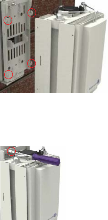
...................................................................................................................................................................................................
7Secure the 9764 9764 CMCO onto the mounting frame by tightening the lever retaining
screw.
...................................................................................................................................................................................................
8Finally, check the 9764 CMCO is correctly locked into position and there is no movement
of the module on the mounting frame.
Installation
Installation
Wall mount the 9764 CMCO
....................................................................................................................................................................................................................................
....................................................................................................................................................................................................................................
9764 CMCO B41 2x6W
3MN-02026-0002-RJZZA
Issue 0.01 April 2015
Alcatel-Lucent – Internal
Proprietary – Use pursuant to Company instruction 4-35
P
RELIMINARY
P
RELIMINARY
END OF STEPS
...................................................................................................................................................................................................
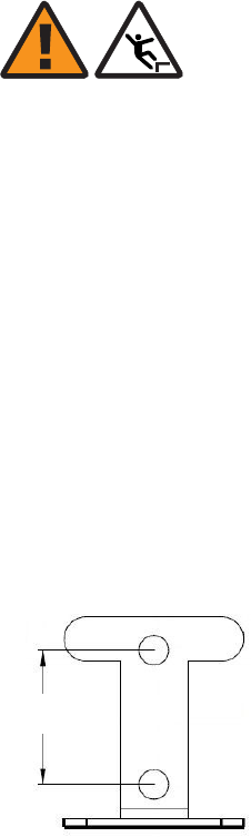
Mount surge arrestor (optional)
WARNING
Fall hazard
Falls can occur when working at heights resulting in serious personal injury or death.
To prevent a fall when working at heights (ladder, scaffold, manlift, roof etc.) follow safe
work practices and wear appropriate fall protection equipment.
Although optional, Alcatel-Lucent strongly recommends for outdoor deployments, that
when the backhaul connection is configured for electrical Ethernet (GBE
10/100/1000BaseT) a surge arrestor is installed, as the electrical SFP does not provide
surge protection.
Follow these steps to attached the surge arrestor bracket to a wall and mount the optional
external surge arrestor onto the surge arrestor bracket.
...................................................................................................................................................................................................
1At the selected mounting location for the surge arrestor, mark the points on the wall for
the mounting bracket anchor holes. See drill hole pattern below to use as a guide:
Tip: The surge arrestor mounting bracket can be used as a template to mark the points
on the wall for the fixing holes.
...................................................................................................................................................................................................
2Drill the upper hole and lower hole at the marked points to the appropriate depth. Insert
screw anchor plugs into the drilled holes and, using a hammer, tap home until the plugs
are flush with the wall.
...................................................................................................................................................................................................
3Align the surge arrestor mounting bracket bolt holes with the drilled wall anchor holes.
Screw the upper and lower bolts into the wall fixings to the appropriate depth so that the
mounting bracket is securely attached to the wall.
30 mm
(1.2 inches)
Installation
Installation
Wall mount the 9764 CMCO
....................................................................................................................................................................................................................................
....................................................................................................................................................................................................................................
4-36 Alcatel-Lucent – Internal
Proprietary – Use pursuant to Company instruction
9764 CMCO B41 2x6W
3MN-02026-0002-RJZZA
Issue 0.01 April 2015
P
RELIMINARY
P
RELIMINARY
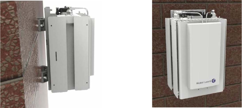
...................................................................................................................................................................................................
4On the surge arrestor, unscrew the lower weatherized strain relief connector and locking
nut from the surge arrestor.
...................................................................................................................................................................................................
5Site the surge arrestor onto the bracket so that the lower threaded Ethernet connection
point is positioned through the arrestor mounting hole.
...................................................................................................................................................................................................
6Screw the arrestor locking nut back onto the arrestor and tighten so that the arrestor is
securely attached to the bracket.
Standard wall mount example
The following figure depicts a standard 9764 CMCO wall mount installation.
How to continue
After mounting the 9764 CMCO onto a wall or flat surface the cables need to be
connected. Continue with the Chapter 5, “Cabling” chapter.
Installation
Installation
Wall mount the 9764 CMCO
....................................................................................................................................................................................................................................
....................................................................................................................................................................................................................................
9764 CMCO B41 2x6W
3MN-02026-0002-RJZZA
Issue 0.01 April 2015
Alcatel-Lucent – Internal
Proprietary – Use pursuant to Company instruction 4-37
P
RELIMINARY
P
RELIMINARY
END OF STEPS
...................................................................................................................................................................................................
Wall mount the 9764 CMCO using optional tilt brackets
Purpose
This topic describes the procedures to be followed when the 9764 CMCO is required to
be mounted onto a wall or solid flat surface using tilt brackets (vertical, horizontal or
combined horizontal/vertical).
Prerequisites
A site survey has been conducted and a location for the device has been selected that is
both central to the public space and elevated in order to maximize coverage. Before
installation begins you should ensure the following are in place:
•Ensure adequate clearance is provided for service access.
•Ground cable has been routed and the site grounding system is in place.
•Backhaul cable has been routed and is in place.
•Any site specific fixing materials are available (for example, bolts, washers and wall
plug materials).
Attention: The 9764 CMCO must be mounted with the appropriate mounting
hardware suitable for the various supporting structures, building materials and
construction methods. Following a site survey, it is the responsibility of the customer
to ensure that:
•The installation support structure is adequate and compliant with ICC IBC (2012):
International Building Code, and all other national and local codes.
•The appropriate mounting hardware and any necessary supporting anchor fixings
are used.
Mounting requirements and materials
The 9764 CMCO can be easily mounted onto solid concrete or wooden flat surface. Refer
to the following for the installation kits, anchor materials and tools for the installation
type:
•For wall mount, refer to “Wall mount installation requirements” (p. 3-7).
•For a list of standard tools that may be required to support the installation, see “Tools
required for installation” (p. 3-3).
Before you begin
Record the 9764 CMCO 18 digit serial number before mounting onto a wall.
Installation
Installation
Wall mount the 9764 CMCO using optional tilt brackets
....................................................................................................................................................................................................................................
....................................................................................................................................................................................................................................
4-38 Alcatel-Lucent – Internal
Proprietary – Use pursuant to Company instruction
9764 CMCO B41 2x6W
3MN-02026-0002-RJZZA
Issue 0.01 April 2015
P
RELIMINARY
P
RELIMINARY
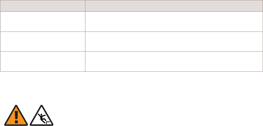
Tilt configurations
Carry out one of the following procedures depending on the required tilt installation
configuration:
If.. Then..
Mounting for vertical tilt
only
Carry out the procedure, “Mount the vertical tilt and 9764
CMCO brackets” (p. 4-39)
Mounting for horizontal tilt
only
Carry out the procedure, “Mount combined horizontal/vertical
tilt and 9764 CMCO brackets” (p. 4-47)
Mounting for combined
horizontal and vertical tilt
Carry out the procedure, “Mount combined horizontal/vertical
tilt and 9764 CMCO brackets” (p. 4-47)
Mount the vertical tilt and 9764 CMCO brackets
WARNING
Fall hazard
Falls can occur when working at heights resulting in serious personal injury or death.
To prevent a fall when working at heights (ladder, scaffold, manlift, roof etc.) follow safe
work practices and wear appropriate fall protection equipment.
Perform the following procedure to mount a vertical tilt bracket onto a flat surface or wall
and then attach the 9764 CMCO bracket.
...................................................................................................................................................................................................
1At the selected installation location, mark the points on the wall for the tilt bracket anchor
holes. See drill hole pattern below to use as a guide:
Installation
Installation
Wall mount the 9764 CMCO using optional tilt brackets
....................................................................................................................................................................................................................................
....................................................................................................................................................................................................................................
9764 CMCO B41 2x6W
3MN-02026-0002-RJZZA
Issue 0.01 April 2015
Alcatel-Lucent – Internal
Proprietary – Use pursuant to Company instruction 4-39
P
RELIMINARY
P
RELIMINARY
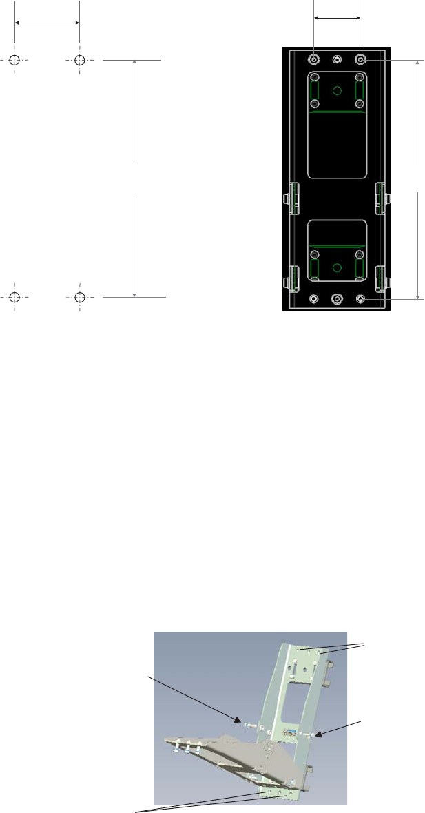
Note: If the vertical tilt bracket is available it can be placed against the wall and be
used as a template to mark the points on the wall for the bracket anchor holes.
Check the horizontal marked position of the holes with a level.
...................................................................................................................................................................................................
2Drill two upper holes and two lower holes at the marked points to the appropriate depth.
Insert screw anchor plugs into the drilled holes and, using a hammer, tap home until the
plugs are flush with the wall.
...................................................................................................................................................................................................
3Remove the two tilt angle positioning gauge bolts on either side of the vertical tilt bracket
and allow the front part of the bracket to pivot away allowing easier access to the bracket
anchor holes.
52 mm
2.0 inches
270 mm
10.6 inches
2.0 inches
10.6 inches
52 mm
270 mm
Tilt angle positioning
gauge bolt
Tilt angle positioning
gauge bolt
Bracket anchor holes
Bracket anchor holes
Installation
Installation
Wall mount the 9764 CMCO using optional tilt brackets
....................................................................................................................................................................................................................................
....................................................................................................................................................................................................................................
4-40 Alcatel-Lucent – Internal
Proprietary – Use pursuant to Company instruction
9764 CMCO B41 2x6W
3MN-02026-0002-RJZZA
Issue 0.01 April 2015
P
RELIMINARY
P
RELIMINARY
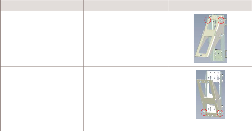
...................................................................................................................................................................................................
4Depending on the required vertical tilt orientation ensure the bracket is positioned the
correct way up before placing on the wall:
If... Then... View...
upward vertical tilt is
required
the tilt bracket must be
positioned with the pivot point
at the top
downward vertical tilt is
required
the tilt bracket must be
positioned with the pivot point
at the bottom
...................................................................................................................................................................................................
5Align the vertical tilt bracket bolt holes with the drilled wall anchor holes. Screw in the
upper and lower bolts into the wall fixings to the appropriate depth so that the tilt bracket
is securely attached to the wall.
Recommended screw torque; 7.0 N.m (62.0 lb.in).
...................................................................................................................................................................................................
6Unscrew and remove the two upper and one lower M6 bolts from the vertical tilt bracket
in readiness for attaching the 9764 CMCO bracket.
Installation
Installation
Wall mount the 9764 CMCO using optional tilt brackets
....................................................................................................................................................................................................................................
....................................................................................................................................................................................................................................
9764 CMCO B41 2x6W
3MN-02026-0002-RJZZA
Issue 0.01 April 2015
Alcatel-Lucent – Internal
Proprietary – Use pursuant to Company instruction 4-41
P
RELIMINARY
P
RELIMINARY

...................................................................................................................................................................................................
7Next, on the reverse side of the 9764 CMCO mounting bracket unscrew the M4 pole grips
bolts and remove the upper and lower pole grips from the bracket.
...................................................................................................................................................................................................
8Position the 9764 CMCO mounting bracket against the front of the tilt bracket so that the
two upper bolt holes and the single lower bolt hole on the 9764 CMCO mounting bracket
are aligned with the bolts holes on the tilt bracket.
From the 9764 CMCO mounting bracket side, screw in the two upper M6 bolts and lower
M6 bolt to attach the 9764 CMCO mounting bracket to the vertical tilt bracket.
Installation
Installation
Wall mount the 9764 CMCO using optional tilt brackets
....................................................................................................................................................................................................................................
....................................................................................................................................................................................................................................
4-42 Alcatel-Lucent – Internal
Proprietary – Use pursuant to Company instruction
9764 CMCO B41 2x6W
3MN-02026-0002-RJZZA
Issue 0.01 April 2015
P
RELIMINARY
P
RELIMINARY
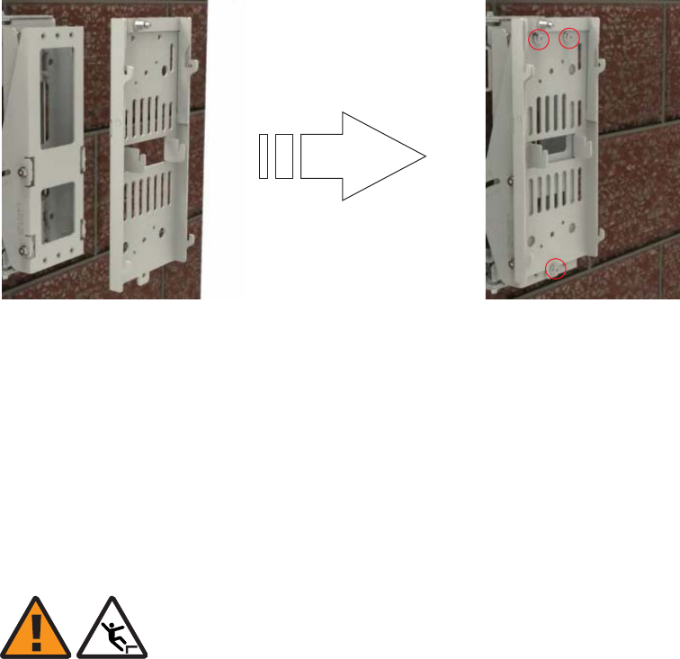
...................................................................................................................................................................................................
9Once the brackets are mounted the 9764 CMCO can be attached. Continue with “Attach
9764 CMCO to the mounting bracket” (p. 4-53).
Mount the horizontal tilt and 9764 CMCO brackets
WARNING
Fall hazard
Falls can occur when working at heights resulting in serious personal injury or death.
To prevent a fall when working at heights (ladder, scaffold, manlift, roof etc.) follow safe
work practices and wear appropriate fall protection equipment.
Perform the following procedure to mount a horizontal tilt bracket onto a flat surface or
wall and then attach the 9764 CMCO bracket.
...................................................................................................................................................................................................
1At the selected installation location, mark the points on the wall for the bracket anchor
holes. See drill hole pattern below to use as a guide:
Installation
Installation
Wall mount the 9764 CMCO using optional tilt brackets
....................................................................................................................................................................................................................................
....................................................................................................................................................................................................................................
9764 CMCO B41 2x6W
3MN-02026-0002-RJZZA
Issue 0.01 April 2015
Alcatel-Lucent – Internal
Proprietary – Use pursuant to Company instruction 4-43
P
RELIMINARY
P
RELIMINARY
END OF STEPS
...................................................................................................................................................................................................

Note: If the horizontal tilt bracket is available it can be placed against the wall and be
used as a template to mark the points on the wall for the bracket anchor holes.
Check the horizontal marked position of the holes with a level.
...................................................................................................................................................................................................
2Drill two upper holes and two lower holes at the marked points to the appropriate depth.
Insert screw anchor plugs into the drilled holes and, using a hammer, tap home until the
plugs are flush with the wall.
...................................................................................................................................................................................................
3Remove the two tilt angle positioning gauge bolts from the top and bottom of the
horizontal tilt bracket and swing the horizontal tilt bracket arms outwards allowing easier
access to the bracket anchor holes.
52 mm
2.0 inches
270 mm
10.6 inches
2.0 inches
10.6 inches
52 mm
270 mm
Installation
Installation
Wall mount the 9764 CMCO using optional tilt brackets
....................................................................................................................................................................................................................................
....................................................................................................................................................................................................................................
4-44 Alcatel-Lucent – Internal
Proprietary – Use pursuant to Company instruction
9764 CMCO B41 2x6W
3MN-02026-0002-RJZZA
Issue 0.01 April 2015
P
RELIMINARY
P
RELIMINARY

...................................................................................................................................................................................................
4Depending on the required horizontal tilt orientation ensure the bracket is the correct way
up before securing the bracket onto the wall:
If... Then... View...
left horizontal tilt is required the tilt bracket must be
positioned with the pivot point
on the left
right horizontal tilt is required the tilt bracket must be
positioned with the pivot point
on the right
...................................................................................................................................................................................................
5Align the horizontal tilt bracket bolt holes with the drilled wall anchor holes and screw in
the upper and lower bolts into the wall fixings to the appropriate depth so that the tilt
bracket is securely attached to the wall.
Swing the horizontal tilt bracket arms inwards and replace the two tilt angle positioning
gauge bolts into the top and bottom of the horizontal tilt bracket.
Tilt angle
positioning gauge bolt
Tilt angle
positioning gauge bolt
Bracket anchor holes
Bracket anchor holes
Installation
Installation
Wall mount the 9764 CMCO using optional tilt brackets
....................................................................................................................................................................................................................................
....................................................................................................................................................................................................................................
9764 CMCO B41 2x6W
3MN-02026-0002-RJZZA
Issue 0.01 April 2015
Alcatel-Lucent – Internal
Proprietary – Use pursuant to Company instruction 4-45
P
RELIMINARY
P
RELIMINARY
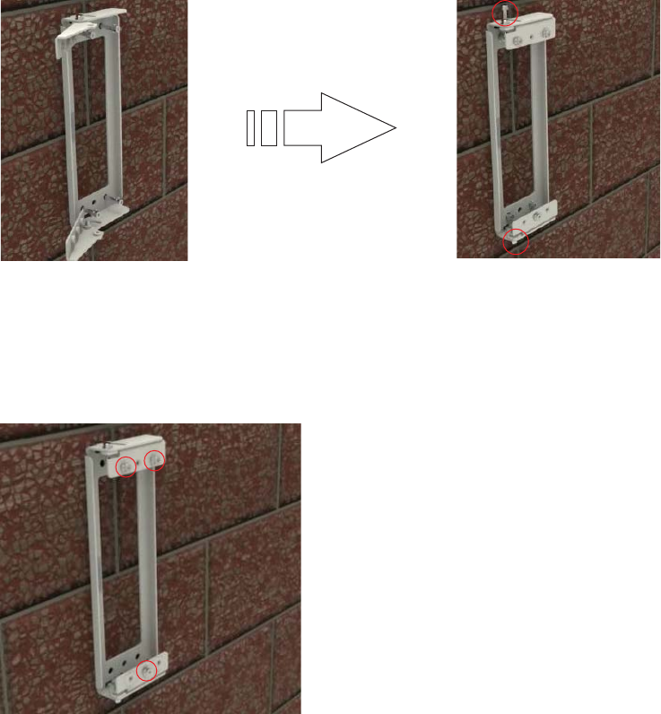
...................................................................................................................................................................................................
6Unscrew and remove the two upper M6 bolts and the one lower M6 bolt from the
horizontal tilt bracket in readiness for attaching the 9764 CMCO bracket.
...................................................................................................................................................................................................
7Position the 9764 CMCO mounting bracket against the front of the horizontal tilt bracket
so that the two upper bolt holes and the single lower bolt hole on the 9764 CMCO
mounting bracket are aligned with the bolts holes on the horizontal tilt bracket.
From the 9764 CMCO mounting bracket side, screw in the two upper M6 bolts and lower
M6 bolt to attach the 9764 CMCO mounting bracket to the horizontal tilt bracket.
Installation
Installation
Wall mount the 9764 CMCO using optional tilt brackets
....................................................................................................................................................................................................................................
....................................................................................................................................................................................................................................
4-46 Alcatel-Lucent – Internal
Proprietary – Use pursuant to Company instruction
9764 CMCO B41 2x6W
3MN-02026-0002-RJZZA
Issue 0.01 April 2015
P
RELIMINARY
P
RELIMINARY
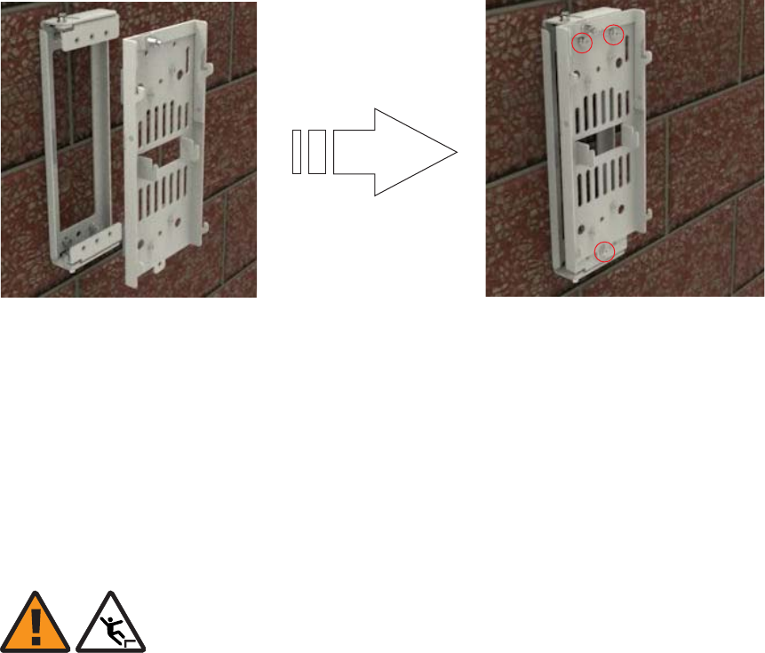
...................................................................................................................................................................................................
8Once the brackets are mounted the 9764 CMCO can be attached. Continue with “Attach
9764 CMCO to the mounting bracket” (p. 4-53).
Mount combined horizontal/vertical tilt and 9764 CMCO brackets
WARNING
Fall hazard
Falls can occur when working at heights resulting in serious personal injury or death.
To prevent a fall when working at heights (ladder, scaffold, manlift, roof etc.) follow safe
work practices and wear appropriate fall protection equipment.
Perform the following procedure to mount combined horizontal/vertical tilt brackets onto
a flat surface or wall and then attach the 9764 CMCO bracket.
...................................................................................................................................................................................................
1At the selected installation location, mark the points on the wall for the bracket anchor
holes. See drill hole pattern below to use as a guide:
Installation
Installation
Wall mount the 9764 CMCO using optional tilt brackets
....................................................................................................................................................................................................................................
....................................................................................................................................................................................................................................
9764 CMCO B41 2x6W
3MN-02026-0002-RJZZA
Issue 0.01 April 2015
Alcatel-Lucent – Internal
Proprietary – Use pursuant to Company instruction 4-47
P
RELIMINARY
P
RELIMINARY
END OF STEPS
...................................................................................................................................................................................................
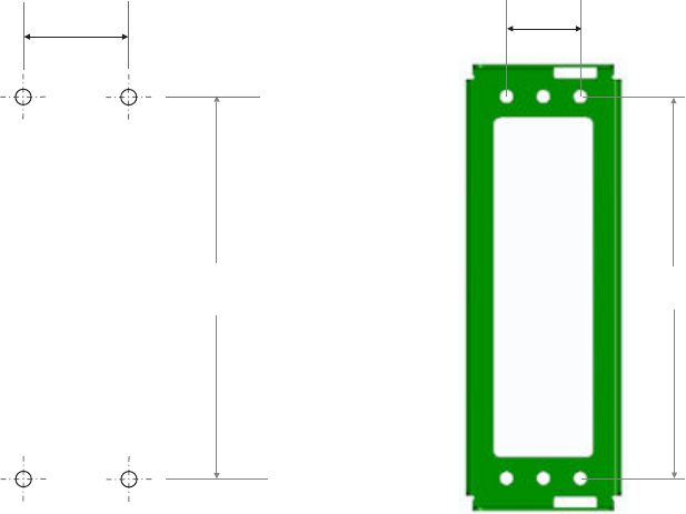
Note: If the horizontal tilt bracket is available it can be placed against the wall and be
used as a template to mark the points on the wall for the bracket anchor holes.
Check the horizontal marked position of the holes with a level.
...................................................................................................................................................................................................
2Drill two upper holes and two lower holes at the marked points to the appropriate depth.
Insert screw anchor plugs into the drilled holes and, using a hammer, tap home until the
plugs are flush with the wall.
...................................................................................................................................................................................................
3Remove the two tilt angle positioning gauge bolts from the top and bottom of the
horizontal tilt bracket and swing the horizontal tilt bracket arms outwards allowing easier
access to the bracket anchor holes.
52 mm
2.0 inches
270 mm
10.6 inches
2.0 inches
10.6 inches
52 mm
270 mm
Installation
Installation
Wall mount the 9764 CMCO using optional tilt brackets
....................................................................................................................................................................................................................................
....................................................................................................................................................................................................................................
4-48 Alcatel-Lucent – Internal
Proprietary – Use pursuant to Company instruction
9764 CMCO B41 2x6W
3MN-02026-0002-RJZZA
Issue 0.01 April 2015
P
RELIMINARY
P
RELIMINARY
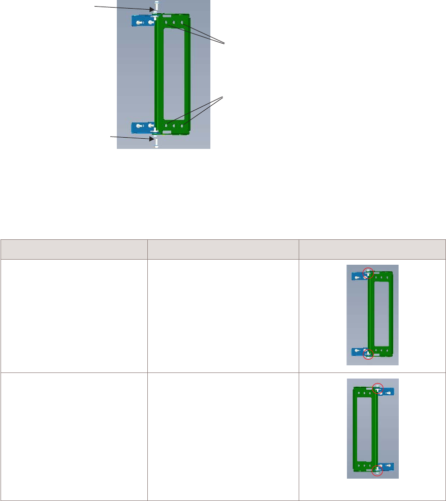
...................................................................................................................................................................................................
4Depending on the required horizontal tilt orientation ensure the bracket is the correct way
up before securing the bracket onto the wall:
If... Then... View...
left horizontal tilt is required the tilt bracket must be
positioned with the pivot point
on the left
right horizontal tilt is required the tilt bracket must be
positioned with the pivot point
on the right
...................................................................................................................................................................................................
5Align the horizontal tilt bracket bolt holes with the drilled wall anchor holes and crew in
the upper and lower bolts into the wall fixings to the appropriate depth so that the bracket
is securely attached to the wall.
Swing the horizontal tilt bracket arms inwards and replace the two tilt angle positioning
gauge bolts into the top and bottom of the horizontal tilt bracket.
Tilt angle
positioning gauge bolt
Tilt angle
positioning gauge bolt
Bracket anchor holes
Bracket anchor holes
Installation
Installation
Wall mount the 9764 CMCO using optional tilt brackets
....................................................................................................................................................................................................................................
....................................................................................................................................................................................................................................
9764 CMCO B41 2x6W
3MN-02026-0002-RJZZA
Issue 0.01 April 2015
Alcatel-Lucent – Internal
Proprietary – Use pursuant to Company instruction 4-49
P
RELIMINARY
P
RELIMINARY
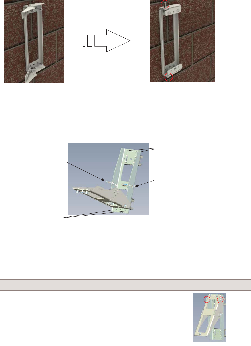
...................................................................................................................................................................................................
6Remove the two tilt angle positioning gauge bolts on either side of the vertical tilt bracket
and allow the front part of the bracket to pivot away allowing easier access to the bracket
anchor holes.
...................................................................................................................................................................................................
7Align the attachment holes on the vertical tilt bracket with the attachments holes on the
horizontal tilt bracket. Depending on the required vertical tilt orientation ensure the
bracket is positioned the correct way up before attaching to the horizontal tilt bracket.
If... Then... View...
upward vertical tilt is
required
the tilt bracket must be
positioned with the pivot point
at the top
Tilt angle positioning
gauge bolt
Tilt angle positioning
gauge bolt
Bracket anchor holes
Bracket anchor holes
Installation
Installation
Wall mount the 9764 CMCO using optional tilt brackets
....................................................................................................................................................................................................................................
....................................................................................................................................................................................................................................
4-50 Alcatel-Lucent – Internal
Proprietary – Use pursuant to Company instruction
9764 CMCO B41 2x6W
3MN-02026-0002-RJZZA
Issue 0.01 April 2015
P
RELIMINARY
P
RELIMINARY
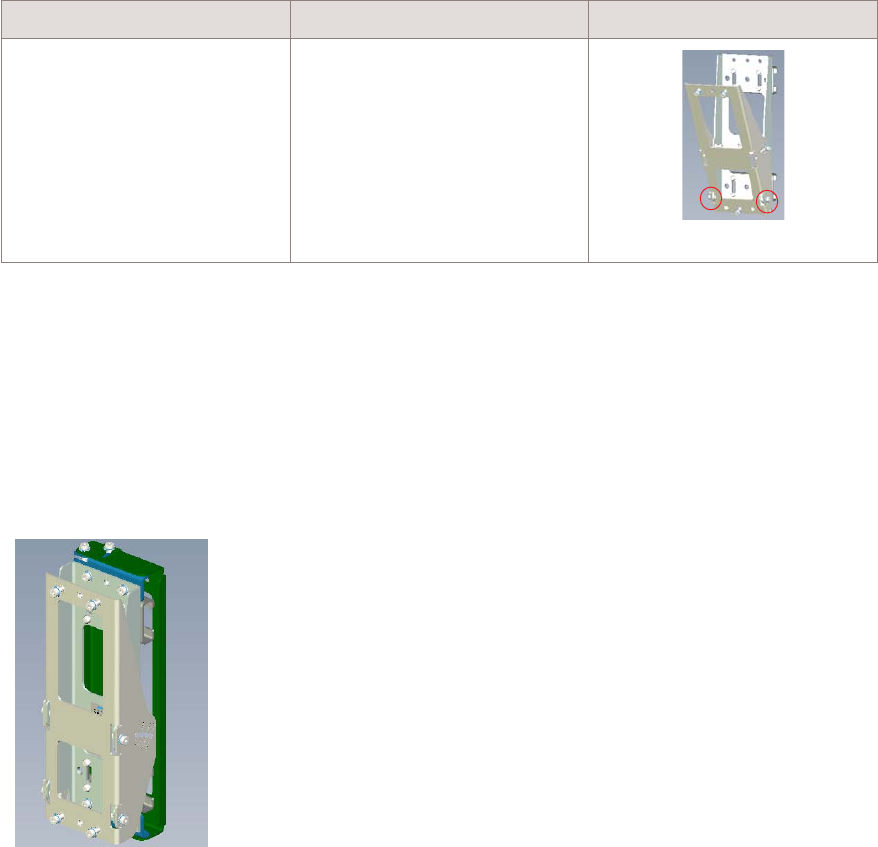
If... Then... View...
downward vertical tilt is
required
the tilt bracket must be
positioned with the pivot point
at the bottom
...................................................................................................................................................................................................
8Insert the two upper and two lower bolts through the attachment holes on the vertical tilt
bracket and through the attachment holes on the horizontal tilt bracket.
For each bolt, screw on the retaining nut. Using a 10 mm ratchet wrench, tighten the two
upper and two lower M6 retaining bolts so that the brackets are securely attached.
Recommended screw torque; 7.0 N.m (62.0 lb.in).
...................................................................................................................................................................................................
9Unscrew and remove the two upper and one lower M6 bolts from the vertical tilt bracket
in readiness for attaching the 9764 CMCO bracket.
Installation
Installation
Wall mount the 9764 CMCO using optional tilt brackets
....................................................................................................................................................................................................................................
....................................................................................................................................................................................................................................
9764 CMCO B41 2x6W
3MN-02026-0002-RJZZA
Issue 0.01 April 2015
Alcatel-Lucent – Internal
Proprietary – Use pursuant to Company instruction 4-51
P
RELIMINARY
P
RELIMINARY
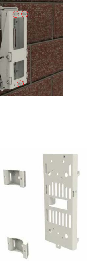
...................................................................................................................................................................................................
10 Next, on the reverse side of the 9764 CMCO mounting bracket unscrew the M4 pole grips
bolts and remove the upper and lower pole grips from the bracket.
...................................................................................................................................................................................................
11 Position the 9764 CMCO mounting bracket against the front of the tilt bracket so that the
two upper bolt holes and the single lower bolt hole on the 9764 CMCO mounting bracket
are aligned with the bolts holes on the tilt bracket.
From the 9764 CMCO mounting bracket side, screw in the two upper and one lower M6
bolts to attach the 9764 CMCO mounting bracket to the vertical tilt bracket.
Installation
Installation
Wall mount the 9764 CMCO using optional tilt brackets
....................................................................................................................................................................................................................................
....................................................................................................................................................................................................................................
4-52 Alcatel-Lucent – Internal
Proprietary – Use pursuant to Company instruction
9764 CMCO B41 2x6W
3MN-02026-0002-RJZZA
Issue 0.01 April 2015
P
RELIMINARY
P
RELIMINARY

...................................................................................................................................................................................................
12 Once the brackets are mounted the 9764 CMCO can be attached. Continue with “Attach
9764 CMCO to the mounting bracket” (p. 4-53).
Attach 9764 CMCO to the mounting bracket
WARNING
Fall hazard
Falls can occur when working at heights resulting in serious personal injury or death.
To prevent a fall when working at heights (ladder, scaffold, manlift, roof etc.) follow safe
work practices and wear appropriate fall protection equipment.
Perform the following procedure to attach the 9764 CMCO to the mounting bracket.
...................................................................................................................................................................................................
1Open the mounting frame lever by pulling the lever outwards.
Installation
Installation
Wall mount the 9764 CMCO using optional tilt brackets
....................................................................................................................................................................................................................................
....................................................................................................................................................................................................................................
9764 CMCO B41 2x6W
3MN-02026-0002-RJZZA
Issue 0.01 April 2015
Alcatel-Lucent – Internal
Proprietary – Use pursuant to Company instruction 4-53
P
RELIMINARY
P
RELIMINARY
END OF STEPS
...................................................................................................................................................................................................
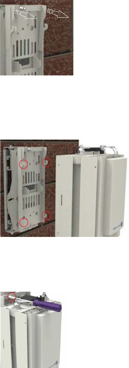
...................................................................................................................................................................................................
2Align the mounting points on the reverse side of the MCO Compact with the mounting
lugs on the bracket. Attach the MCO Compact to the bracket by sliding the MCO
Compact forwards and downwards onto the bracket mounting lugs.
...................................................................................................................................................................................................
3Secure the MCO Compact onto the mounting frame by tightening the lever retaining
screw.
Installation
Installation
Wall mount the 9764 CMCO using optional tilt brackets
....................................................................................................................................................................................................................................
....................................................................................................................................................................................................................................
4-54 Alcatel-Lucent – Internal
Proprietary – Use pursuant to Company instruction
9764 CMCO B41 2x6W
3MN-02026-0002-RJZZA
Issue 0.01 April 2015
P
RELIMINARY
P
RELIMINARY
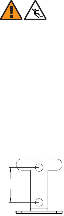
...................................................................................................................................................................................................
4Finally, check the 9764 CMCO is correctly locked into position and there is no movement
of the module on the mounting frame.
Mount surge arrestor (optional)
WARNING
Fall hazard
Falls can occur when working at heights resulting in serious personal injury or death.
To prevent a fall when working at heights (ladder, scaffold, manlift, roof etc.) follow safe
work practices and wear appropriate fall protection equipment.
Although optional, Alcatel-Lucent strongly recommends for outdoor deployments, that
when the backhaul connection is configured for electrical Ethernet (GBE
10/100/1000BaseT) a surge arrestor is installed, as the electrical SFP does not provide
surge protection.
Follow these steps to attached the surge arrestor bracket to a wall and mount the optional
external surge arrestor onto the surge arrestor bracket.
...................................................................................................................................................................................................
1At the selected mounting location for the surge arrestor, mark the points on the wall for
the mounting bracket anchor holes. See drill hole pattern below to use as a guide:
Tip: The surge arrestor mounting bracket can be used as a template to mark the points
on the wall for the fixing holes.
30 mm
(1.2 inches)
Installation
Installation
Wall mount the 9764 CMCO using optional tilt brackets
....................................................................................................................................................................................................................................
....................................................................................................................................................................................................................................
9764 CMCO B41 2x6W
3MN-02026-0002-RJZZA
Issue 0.01 April 2015
Alcatel-Lucent – Internal
Proprietary – Use pursuant to Company instruction 4-55
P
RELIMINARY
P
RELIMINARY
END OF STEPS
...................................................................................................................................................................................................
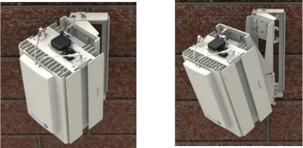
...................................................................................................................................................................................................
2Drill the upper hole and lower hole at the marked points to the appropriate depth. Insert
screw anchor plugs into the drilled holes and, using a hammer, tap home until the plugs
are flush with the wall.
...................................................................................................................................................................................................
3Align the surge arrestor mounting bracket bolt holes with the drilled wall anchor holes.
Screw the upper and lower bolts into the wall fixings to the appropriate depth so that the
mounting bracket is securely attached to the wall.
...................................................................................................................................................................................................
4On the surge arrestor, unscrew the lower weatherized strain relief connector and locking
nut from the surge arrestor.
...................................................................................................................................................................................................
5Site the surge arrestor onto the bracket so that the lower threaded Ethernet connection
point is positioned through the arrestor mounting hole.
...................................................................................................................................................................................................
6Screw the arrestor locking nut back onto the arrestor and tighten so that the arrestor is
securely attached to the bracket.
Wall mount with horizontal/vertical tilt example
The following figure depicts a 9764 CMCO wall mount installation with
horizontal/vertical tilt.
Wall mount horizontal tilt only Wall mount horizontal
and vertical tilt
Installation
Installation
Wall mount the 9764 CMCO using optional tilt brackets
....................................................................................................................................................................................................................................
....................................................................................................................................................................................................................................
4-56 Alcatel-Lucent – Internal
Proprietary – Use pursuant to Company instruction
9764 CMCO B41 2x6W
3MN-02026-0002-RJZZA
Issue 0.01 April 2015
P
RELIMINARY
P
RELIMINARY
END OF STEPS
...................................................................................................................................................................................................
How to continue
After mounting the 9764 CMCO onto a wall the cables need to be connected. Continue
with the Chapter 5, “Cabling” chapter.
Installation
Installation
Wall mount the 9764 CMCO using optional tilt brackets
....................................................................................................................................................................................................................................
....................................................................................................................................................................................................................................
9764 CMCO B41 2x6W
3MN-02026-0002-RJZZA
Issue 0.01 April 2015
Alcatel-Lucent – Internal
Proprietary – Use pursuant to Company instruction 4-57
P
RELIMINARY
P
RELIMINARY
Installation Wall mount the 9764 CMCO using optional tilt brackets
....................................................................................................................................................................................................................................
....................................................................................................................................................................................................................................
4-58 Alcatel-Lucent – Internal
Proprietary – Use pursuant to Company instruction
9764 CMCO B41 2x6W
3MN-02026-0002-RJZZA
Issue 0.01 April 2015
P
RELIMINARY
P
RELIMINARY

55Cabling
Overview
Purpose
This chapter provides instructions for routing and connecting the following cables to the
9764 CMCO:
•Ground cable
•External RF antenna cable
•External GPS antenna cable
•Power cable
Contents
Connect ground cable 5-2
Connect RF antennas 5-4
Connect GPS antenna 5-8
Connect power cable 5-12
...................................................................................................................................................................................................................................
9764 CMCO B41 2x6W
3MN-02026-0002-RJZZA
Issue 0.01 April 2015
Alcatel-Lucent – Internal
Proprietary – Use pursuant to Company instruction 5-1
P
RELIMINARY
P
RELIMINARY
Connect ground cable
Purpose
Follow this procedure to connect the ground cable to the 9764 CMCO.
Before you begin
Ensure the following:
•All site preparation activities for cabling have been completed.
•All installation procedures for the 9764 CMCO have been completed.
Steps
Note: The 9764 CMCO must be grounded with a 16 mm2ground cable (Type
NYY-1x16 mm2or similar) to a grounding system.
The grounding cable is not included in the delivery and must be locally supplied.
To attach the ground cable perform the following steps:
...................................................................................................................................................................................................
1Route the ground cable from the ground system to the 9764 CMCO.
...................................................................................................................................................................................................
2At the 9764 CMCO, cut the cable to a proper length, strip the cable end and crimp a
2-hole ground lug, with holes suitable for M6 screws, on the end of the cable.
Clean the contact surface area and use antioxidant to avoid oxidation.
...................................................................................................................................................................................................
3Connect the ground lug to the grounding point on the 9764 CMCO using the supplied M6
screws, lock washers, and flat washers. Use antioxidant at the grounding pads.
Cabling Connect ground cable
....................................................................................................................................................................................................................................
....................................................................................................................................................................................................................................
5-2 Alcatel-Lucent – Internal
Proprietary – Use pursuant to Company instruction
9764 CMCO B41 2x6W
3MN-02026-0002-RJZZA
Issue 0.01 April 2015
P
RELIMINARY
P
RELIMINARY

...................................................................................................................................................................................................
4Finally, secure the grounding cable to the wall or pole.
Figure 5-1 Position of grounding point
Double lug
ground point
Cabling Connect ground cable
....................................................................................................................................................................................................................................
....................................................................................................................................................................................................................................
9764 CMCO B41 2x6W
3MN-02026-0002-RJZZA
Issue 0.01 April 2015
Alcatel-Lucent – Internal
Proprietary – Use pursuant to Company instruction 5-3
P
RELIMINARY
P
RELIMINARY
END OF STEPS
...................................................................................................................................................................................................

Connect RF antennas
Purpose
Two RF antenna connectors are located externally on the top of the 9764 CMCO, giving
the service provider the option of either connecting an attached RF antenna or connecting
to two externally cabled RF antennas.
Use this procedure to connect RF antenna cables to the 9764 CMCO.
Note: Alcatel-Lucent supplies the attached RF antenna attached to a solar shield.
Alcatel-Lucent does not supply external RF antennas for the 9764 CMCO.
Before you begin
Ensure that the following tools are available:
•Adjustable (crescent) wrenches
•Torque ratchet (socket wrench)
•Items such as crimping tools that are appropriate for attaching a new cable connector
to the RF antenna cable
•Protective eye wear
Safety statements
WARNING
Fall hazard
Falls can occur when working at heights resulting in serious personal injury or death.
To prevent a fall when working at heights (ladder, scaffold, manlift, roof etc.) follow safe
work practices and wear appropriate fall protection equipment.
These admonishments apply throughout this procedure. Refer to the Safety statements
chapter for general safety information.
Connect attached RF antennas
Use this procedure to attach and connect the attached RF antenna.
...................................................................................................................................................................................................
1If a solar shield (without an RF antenna attached) is already attached to the 9764 CMCO,
then remove the solar shield from the 9764 CMCO by pressing the two levers (1 in the
figure below) and sliding the solar shield (2 in the figure) upwards. No tools are required
to do this.
Cabling Connect RF antennas
....................................................................................................................................................................................................................................
....................................................................................................................................................................................................................................
5-4 Alcatel-Lucent – Internal
Proprietary – Use pursuant to Company instruction
9764 CMCO B41 2x6W
3MN-02026-0002-RJZZA
Issue 0.01 April 2015
P
RELIMINARY
P
RELIMINARY
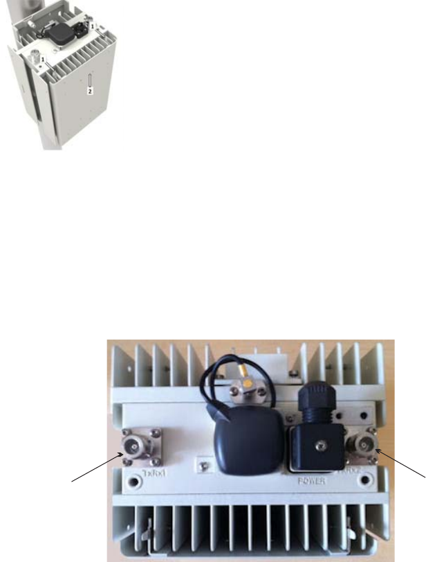
...................................................................................................................................................................................................
2Attach the solar shield (to which the RF antenna is fixed) to the 9764 CMCO by placing it
on the front of the 9764 CMCO and sliding it downwards until a click is heard.
...................................................................................................................................................................................................
3Locate the N-type RF antenna connectors on the top of the 9764 CMCO.
...................................................................................................................................................................................................
4Connect each antenna cable by pushing the antenna cable connector onto the N-type
connector on the top of 9764 CMCO and firmly tighten the connectors by hand.
RF antenna
connector
(N-type)
RF antenna
connector
(N-type)
9764 Compact MCO (top view)
Cabling Connect RF antennas
....................................................................................................................................................................................................................................
....................................................................................................................................................................................................................................
9764 CMCO B41 2x6W
3MN-02026-0002-RJZZA
Issue 0.01 April 2015
Alcatel-Lucent – Internal
Proprietary – Use pursuant to Company instruction 5-5
P
RELIMINARY
P
RELIMINARY
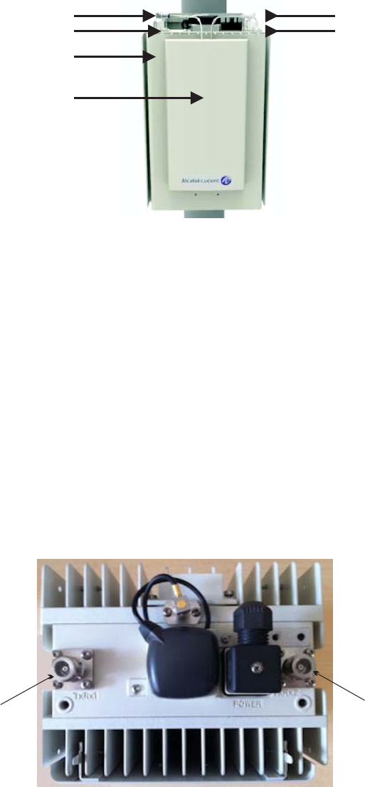
Connect external RF antennas
Use this procedure to connect external RF antennas.
...................................................................................................................................................................................................
1Refer to the RF antenna mounting instructions included with the RF antenna kit for the
steps to mount the antennas.
...................................................................................................................................................................................................
2Locate the N-type RF antenna connectors on the top of the 9764 CMCO.
RF antenna connector
Solar shield
RF antenna
RF antenna connector
Lever Lever
RF antenna
connector
(N-type)
RF antenna
connector
(N-type)
9764 Compact MCO (top view)
Cabling Connect RF antennas
....................................................................................................................................................................................................................................
....................................................................................................................................................................................................................................
5-6 Alcatel-Lucent – Internal
Proprietary – Use pursuant to Company instruction
9764 CMCO B41 2x6W
3MN-02026-0002-RJZZA
Issue 0.01 April 2015
P
RELIMINARY
P
RELIMINARY
END OF STEPS
...................................................................................................................................................................................................
...................................................................................................................................................................................................
3Connect each RF adapter cable by pushing the adapter cable connector onto the 9764
CMCO N-type connector until it clicks into place.
Cabling Connect RF antennas
....................................................................................................................................................................................................................................
....................................................................................................................................................................................................................................
9764 CMCO B41 2x6W
3MN-02026-0002-RJZZA
Issue 0.01 April 2015
Alcatel-Lucent – Internal
Proprietary – Use pursuant to Company instruction 5-7
P
RELIMINARY
P
RELIMINARY
END OF STEPS
...................................................................................................................................................................................................
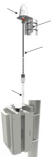
Connect GPS antenna
Purpose
Use this procedure to connect an external (remote) GPS antenna cable to the 9764
CMCO.
Integrated GPS antenna
The 9764 CMCO is supplied with an integrated GPS antenna attached to the top of the
MCO, and connected to the QMA connector on the top of the MCO. The integrated GPS
antenna is a part of the 9764 CMCO and must not be removed, even if you are intend to
connect an external GPS antenna.
External GPS antenna
The following figure shows the external GPS antenna and its mounting kit:
Figure 5-2 External GPS antenna configuration
GPS adaptor cable
9764 Compact MCO
GPS antenna cable
GPS antenna
mounting kit
External GPS antenna
Cabling Connect GPS antenna
....................................................................................................................................................................................................................................
....................................................................................................................................................................................................................................
5-8 Alcatel-Lucent – Internal
Proprietary – Use pursuant to Company instruction
9764 CMCO B41 2x6W
3MN-02026-0002-RJZZA
Issue 0.01 April 2015
P
RELIMINARY
P
RELIMINARY
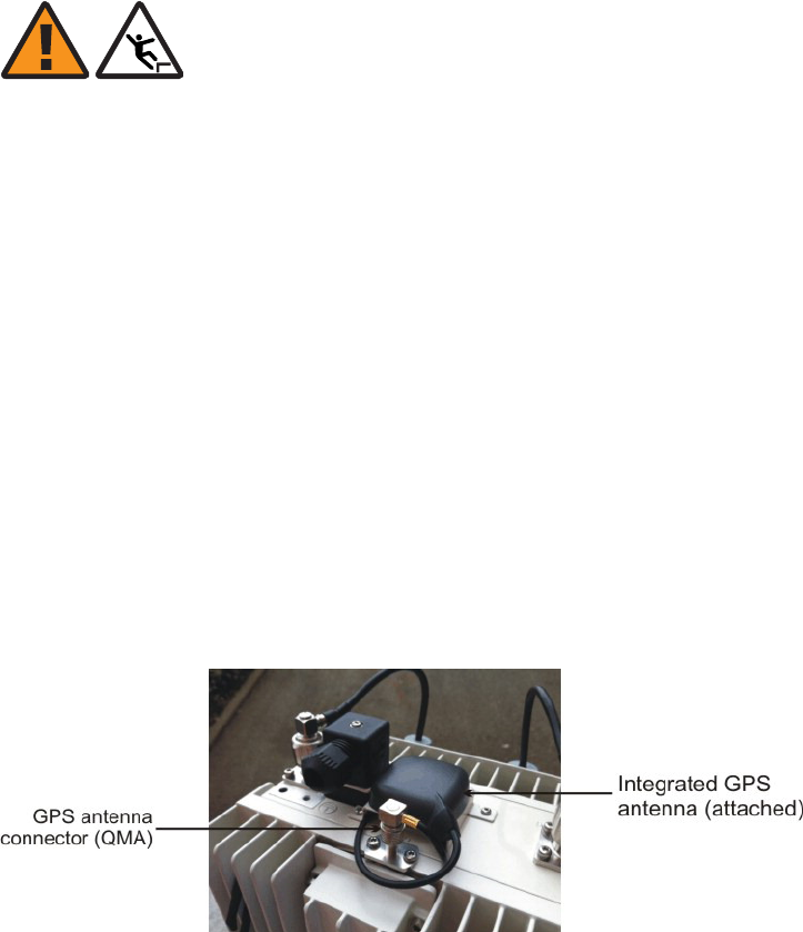
Before you begin
Ensure that the following tools are available:
•Adjustable (crescent) wrenches
•Torque ratchet (socket wrench)
•Items such as crimping tools that are appropriate for attaching a new cable connector
to the GPS cable
•Protective eye wear
Important! Do not mount the GPS antenna within 10 feet (3 m) of any transmit
antenna.
Safety statements
WARNING
Fall hazard
Falls can occur when working at heights resulting in serious personal injury or death.
To prevent a fall when working at heights (ladder, scaffold, manlift, roof etc.) follow safe
work practices and wear appropriate fall protection equipment.
These admonishments apply throughout this procedure. Refer to the Safety statements
chapter for general safety information.
Connect external GPS antenna
...................................................................................................................................................................................................
1Refer to the GPS antenna mounting instructions included with the GPS antenna kit for the
steps to mount the antenna.
...................................................................................................................................................................................................
2Locate the GPS antenna connector on the top of the 9764 CMCO.
Figure 5-3 External GPS antenna connector
Cabling Connect GPS antenna
....................................................................................................................................................................................................................................
....................................................................................................................................................................................................................................
9764 CMCO B41 2x6W
3MN-02026-0002-RJZZA
Issue 0.01 April 2015
Alcatel-Lucent – Internal
Proprietary – Use pursuant to Company instruction 5-9
P
RELIMINARY
P
RELIMINARY
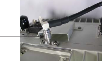
...................................................................................................................................................................................................
3Disconnect the integrated GPS antenna cable from the GPS antenna connector on the top
of the MCO.
...................................................................................................................................................................................................
4Connect the GPS adapter cable by pushing the adapter cable connector onto the 9764
CMCO QMA-type GPS antenna connector until it clicks into place.
...................................................................................................................................................................................................
5Apply weatherizing tape at the point indicated by the red arrows shown in the following
figure:
Cable connector
MCO QMA connector
Cabling Connect GPS antenna
....................................................................................................................................................................................................................................
....................................................................................................................................................................................................................................
5-10 Alcatel-Lucent – Internal
Proprietary – Use pursuant to Company instruction
9764 CMCO B41 2x6W
3MN-02026-0002-RJZZA
Issue 0.01 April 2015
P
RELIMINARY
P
RELIMINARY
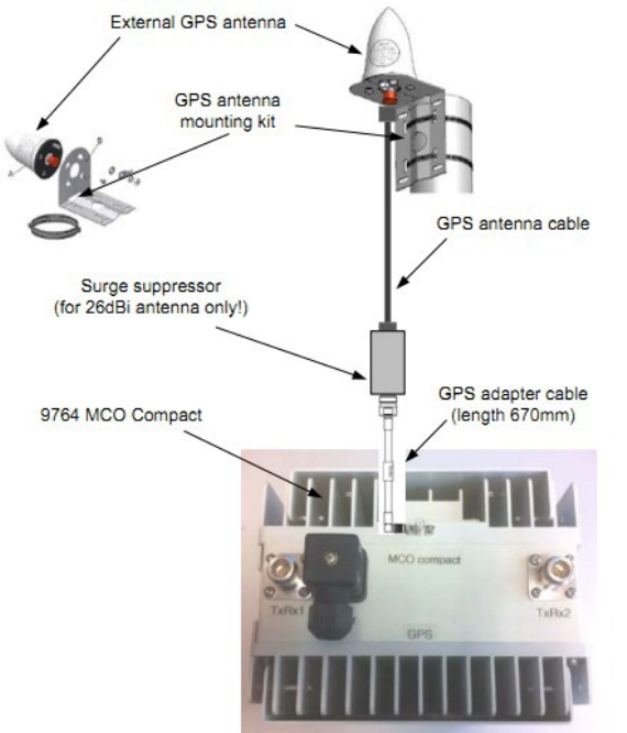
First, apply Linerless rubber splicing tape, then apply vinyl electrical tape over the
Linerless rubber splicing tape.
Cabling Connect GPS antenna
....................................................................................................................................................................................................................................
....................................................................................................................................................................................................................................
9764 CMCO B41 2x6W
3MN-02026-0002-RJZZA
Issue 0.01 April 2015
Alcatel-Lucent – Internal
Proprietary – Use pursuant to Company instruction 5-11
P
RELIMINARY
P
RELIMINARY
END OF STEPS
...................................................................................................................................................................................................
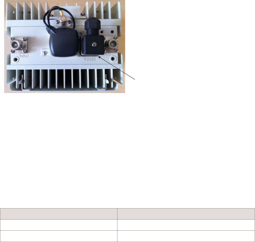
Connect power cable
Purpose
This topic describes the procedures to be followed when connecting the power cable to
the 9764 CMCO.
Connections
The following figure shows the power connection interface of the 9764 CMCO:
Power cable
The 9764 CMCO is equipped with a Standard IEC60320 C16 power socket. The
Alcatel-Lucent supplied power cable and connector should be used with this equipment.
Before you begin
Depending on whether your 9764 CMCO requires AC or DC power, select the
appropriate procedure from the following table:
If... Then follow this procedure
your MCO requires AC power “Connect AC power cord” (p. 5-13)
your MCO requires DC power “Connect DC power cord” (p. 5-14)
Figure 5-4 Power connection interface
Power connector
(connector attached)
9764 Compact MCO (top view)
Cabling Connect power cable
....................................................................................................................................................................................................................................
....................................................................................................................................................................................................................................
5-12 Alcatel-Lucent – Internal
Proprietary – Use pursuant to Company instruction
9764 CMCO B41 2x6W
3MN-02026-0002-RJZZA
Issue 0.01 April 2015
P
RELIMINARY
P
RELIMINARY
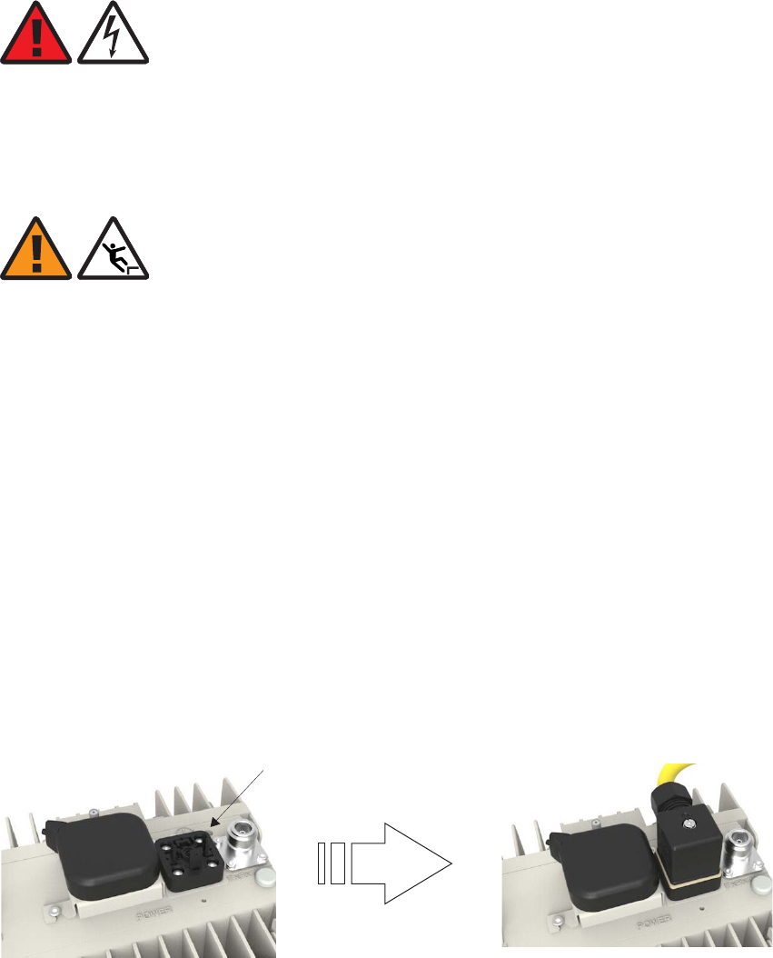
In the United States and Canada, outdoor cords, whether installed as cord pendants or
with mating plug/receptacles, shall comply with NEC Article 400 or Canadian Electrical
Code, Part I Rule 4-012.
Connect AC power cord
DANGER
Electric-shock hazard
Since the 9764 CMCO operates on 120-220 V AC, the risk of serious injury or death from
electrocution exists throughout this procedure.
Follow the first step of this procedure carefully and completely.
WARNING
Fall hazard
Falls can occur when working at heights resulting in serious personal injury or death.
To prevent a fall when working at heights (ladder, scaffold, manlift, roof etc.) follow safe
work practices and wear appropriate fall protection equipment.
...................................................................................................................................................................................................
1Ensure that the power that feeds the AC power cable to the 9764 CMCO is OFF, and
block access so that no one can restore power to that cable during this procedure.
...................................................................................................................................................................................................
2Plug the AC power connector on the power cord into the power connector on the top of
the 9764 CMCO module.
...................................................................................................................................................................................................
3Fix the AC power connector in position by tightening the screw on the AC power
connector. Using a screwdriver with a Phillips head, torque to 0.4 Nm (0.295 lb ft).
Power connection
point on 9764 CMCO
Cabling Connect power cable
....................................................................................................................................................................................................................................
....................................................................................................................................................................................................................................
9764 CMCO B41 2x6W
3MN-02026-0002-RJZZA
Issue 0.01 April 2015
Alcatel-Lucent – Internal
Proprietary – Use pursuant to Company instruction 5-13
P
RELIMINARY
P
RELIMINARY
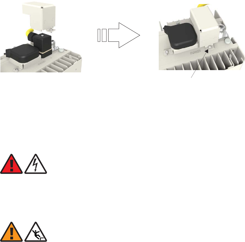
...................................................................................................................................................................................................
4Lower the power connector cover over the power connector, align the captive TORX
M3x5 attachment screw on the power connector cover with the screw hole in the 9764
CMCO, and fix the power connector cover in position by inserting the screw into the
screw hole and tightening.
Connect DC power cord
DANGER
Electric-shock hazard
Since the 9764 CMCO operates on DC power, the risk of serious injury or death from
electrocution exists throughout this procedure.
Follow the first step of this procedure carefully and completely.
WARNING
Fall hazard
Falls can occur when working at heights resulting in serious personal injury or death.
To prevent a fall when working at heights (ladder, scaffold, manlift, roof etc.) follow safe
work practices and wear appropriate fall protection equipment.
Captive TORX
M3x5 screw
Power connector
cover
Cabling Connect power cable
....................................................................................................................................................................................................................................
....................................................................................................................................................................................................................................
5-14 Alcatel-Lucent – Internal
Proprietary – Use pursuant to Company instruction
9764 CMCO B41 2x6W
3MN-02026-0002-RJZZA
Issue 0.01 April 2015
P
RELIMINARY
P
RELIMINARY
END OF STEPS
...................................................................................................................................................................................................
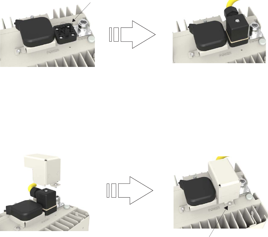
...................................................................................................................................................................................................
1Ensure that the power that feeds the DC power cable to the 9764 CMCO is OFF, and
block access so that no one can restore power to that cable during this procedure.
...................................................................................................................................................................................................
2Plug the DC power connector on the power cord into the power connector on the top of
the 9764 CMCO module.
...................................................................................................................................................................................................
3Fix the DC power connector in position by tightening the screw on the DC power
connector. Using a screwdriver with a Phillips head, torque to 0.4 Nm (0.295 lb ft).
...................................................................................................................................................................................................
4Lower the power connector cover over the power connector, align the captive TORX
M3x5 attachment screw on the power connector cover with the screw hole in the 9764
CMCO, and fix the power connector cover in position by inserting the screw into the
screw hole and tightening.
Power connection
point on 9764 CMCO
Captive TORX
M3x5 screw
Power connector
cover
Cabling Connect power cable
....................................................................................................................................................................................................................................
....................................................................................................................................................................................................................................
9764 CMCO B41 2x6W
3MN-02026-0002-RJZZA
Issue 0.01 April 2015
Alcatel-Lucent – Internal
Proprietary – Use pursuant to Company instruction 5-15
P
RELIMINARY
P
RELIMINARY
END OF STEPS
...................................................................................................................................................................................................
Cabling Connect power cable
....................................................................................................................................................................................................................................
....................................................................................................................................................................................................................................
5-16 Alcatel-Lucent – Internal
Proprietary – Use pursuant to Company instruction
9764 CMCO B41 2x6W
3MN-02026-0002-RJZZA
Issue 0.01 April 2015
P
RELIMINARY
P
RELIMINARY

66Post-installation
Overview
Purpose
This chapter provides post-installation information and activities that should be carried
out after the Alcatel-Lucent 9764 Compact Metro Cell Outdoor has been installed.
Contents
Final installation activities and checks 6-2
...................................................................................................................................................................................................................................
9764 CMCO B41 2x6W
3MN-02026-0002-RJZZA
Issue 0.01 April 2015
Alcatel-Lucent – Internal
Proprietary – Use pursuant to Company instruction 6-1
P
RELIMINARY
P
RELIMINARY
Final installation activities and checks
Overview
This topic describes the final Alcatel-Lucent 9764 Compact Metro Cell Outdoor
installation activities and checks to be carried out.
Final installation checks
Before leaving the installation site, check the following:
...................................................................................................................................................................................................
1Check the overall installation. Verify that mounted equipment is secure and that no
unintentional mechanical alteration has occurred to either the equipment itself or the
installation infrastructure.
...................................................................................................................................................................................................
2Ensure all the exterior connections are secure.
...................................................................................................................................................................................................
3Ensure all cables are secured along their routes.
...................................................................................................................................................................................................
4Finally, inspect the site for loose tools, materials, and parts. Remove all such loose tools,
materials, and parts.
Post-installation Final installation activities and checks
....................................................................................................................................................................................................................................
....................................................................................................................................................................................................................................
6-2 Alcatel-Lucent – Internal
Proprietary – Use pursuant to Company instruction
9764 CMCO B41 2x6W
3MN-02026-0002-RJZZA
Issue 0.01 April 2015
P
RELIMINARY
P
RELIMINARY
END OF STEPS
...................................................................................................................................................................................................

Appendix A: 9764 CMCO service
position
Overview
Purpose
This appendix provides instructions on how to place the 9764 CMCO into the service
position, allowing access to the backhaul module.
Contents
9764 CMCO service position A-2
...................................................................................................................................................................................................................................
9764 CMCO B41 2x6W
3MN-02026-0002-RJZZA
Issue 0.01 April 2015
Alcatel-Lucent – Internal
Proprietary – Use pursuant to Company instruction A-1
P
RELIMINARY
P
RELIMINARY
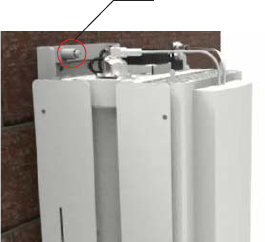
9764 CMCO service position
When to use
Use the following procedures to place the 9764 CMCO in and out of the service position.
Placing the 9764 CMCO into the service position
Carry out the following to place the 9764 CMCO into the service position:
...................................................................................................................................................................................................
1Unscrew the mounting lever retaining screw.
...................................................................................................................................................................................................
2Lift the 9764 CMCO and remove it from the bracket.
...................................................................................................................................................................................................
3Turn the 9764 CMCO through 90° and align the mounting points on the side of the 9764
CMCO with the mounting lugs on the bracket.
...................................................................................................................................................................................................
4Attach the 9764 CMCO to the bracket by sliding the 9764 CMCO forwards and
downwards onto the bracket mounting lugs.
Lever retaining screw
9764 CMCO service position 9764 CMCO service position
....................................................................................................................................................................................................................................
....................................................................................................................................................................................................................................
A-2 Alcatel-Lucent – Internal
Proprietary – Use pursuant to Company instruction
9764 CMCO B41 2x6W
3MN-02026-0002-RJZZA
Issue 0.01 April 2015
P
RELIMINARY
P
RELIMINARY
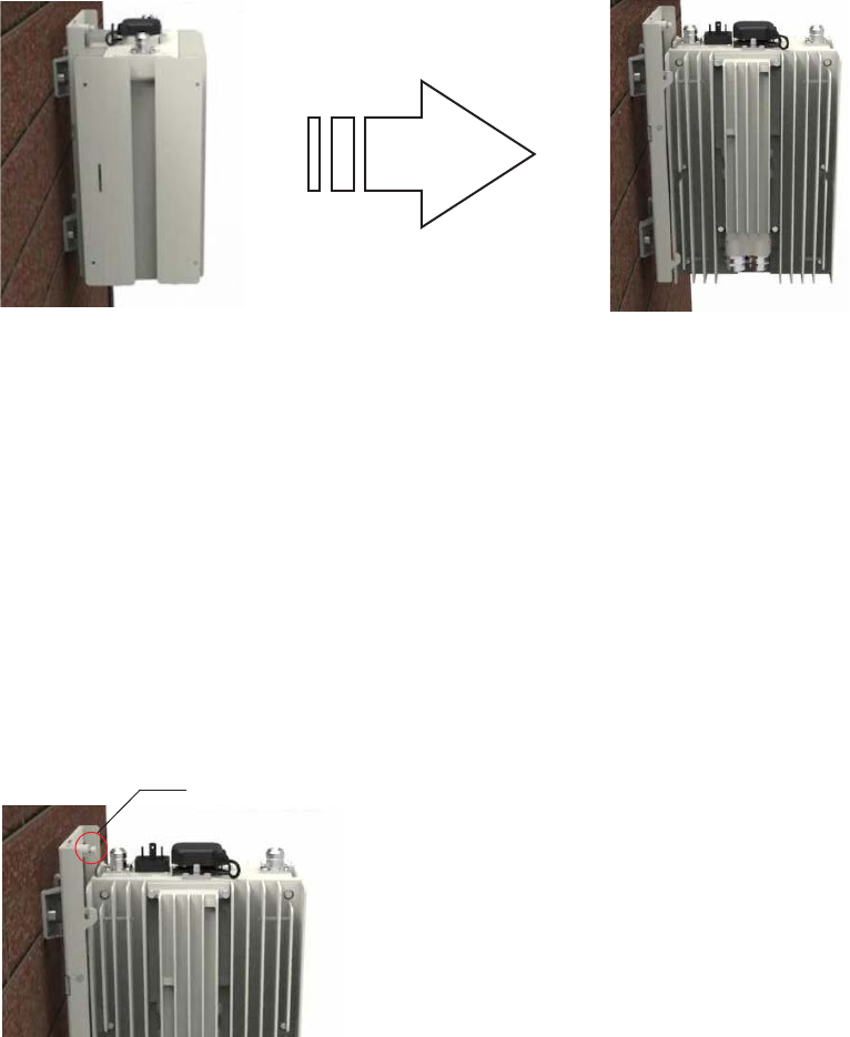
...................................................................................................................................................................................................
5Secure the 9764 CMCO onto the mounting frame by tightening the lever retaining screw.
Placing the 9764 CMCO into the normal position
Carry out the following to place the 9764 CMCO into the normal position:
...................................................................................................................................................................................................
1Unscrew the mounting lever retaining screw.
...................................................................................................................................................................................................
2Lift the 9764 CMCO and remove it from the bracket.
...................................................................................................................................................................................................
3Turn the 9764 CMCO through 90° and align the mounting points on the back of the 9764
CMCO with the mounting lugs on the bracket.
Lever retaining screw
9764 CMCO service position 9764 CMCO service position
....................................................................................................................................................................................................................................
....................................................................................................................................................................................................................................
9764 CMCO B41 2x6W
3MN-02026-0002-RJZZA
Issue 0.01 April 2015
Alcatel-Lucent – Internal
Proprietary – Use pursuant to Company instruction A-3
P
RELIMINARY
P
RELIMINARY
END OF STEPS
...................................................................................................................................................................................................
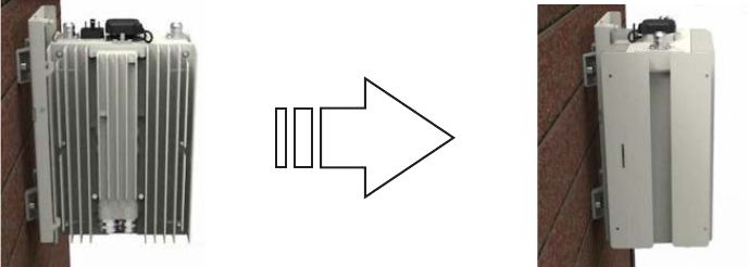
...................................................................................................................................................................................................
4Attach the 9764 CMCO to the bracket by sliding the 9764 CMCO forwards and
downwards onto the bracket mounting lugs.
...................................................................................................................................................................................................
5Secure the 9764 CMCO onto the mounting frame by tightening the lever retaining screw.
9764 CMCO service position 9764 CMCO service position
....................................................................................................................................................................................................................................
....................................................................................................................................................................................................................................
A-4 Alcatel-Lucent – Internal
Proprietary – Use pursuant to Company instruction
9764 CMCO B41 2x6W
3MN-02026-0002-RJZZA
Issue 0.01 April 2015
P
RELIMINARY
P
RELIMINARY
END OF STEPS
...................................................................................................................................................................................................

Appendix B: LED State
Description
Overview
Purpose
This chapter describes the LED status and descriptions for 9764 CMCO.
Contents
LED status for 9764 CMCO B-2
...................................................................................................................................................................................................................................
9764 CMCO B41 2x6W
3MN-02026-0002-RJZZA
Issue 0.01 April 2015
Alcatel-Lucent – Internal
Proprietary – Use pursuant to Company instruction B-1
P
RELIMINARY
P
RELIMINARY
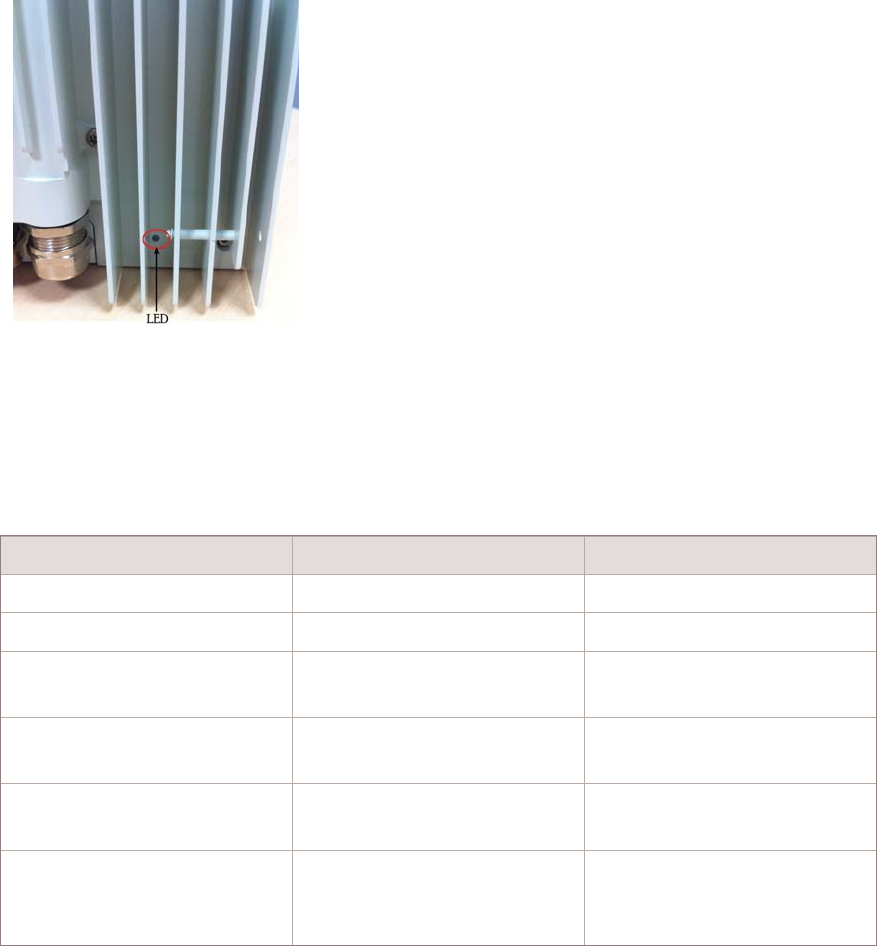
LED status for 9764 CMCO
Location of LED
The following figure shows the location of the LED on the back of the 9764 CMCO:
Hardware LED interpretation table
The following table describes the possible states for the single bi-color LED:
Table B-1 LED statuses
State Description LED
Power off Power off OFF
Initial state Power on or Restart ON (Red)
Software downloading during
system initialization
Software downloading Blinking (Green)
Failure 9764 CMCO LTE start-up or
operational failure
ON (Red)
9764 CMCO LTE becomes
operational
9764 CMCO LTE becoming
operational
ON (Green)
9764 CMCO LTE is
operational
9764 CMCO LTE has been in
stable operation for 15
minutes
OFF
LED State Description LED status for 9764 CMCO
....................................................................................................................................................................................................................................
....................................................................................................................................................................................................................................
B-2 Alcatel-Lucent – Internal
Proprietary – Use pursuant to Company instruction
9764 CMCO B41 2x6W
3MN-02026-0002-RJZZA
Issue 0.01 April 2015
P
RELIMINARY
P
RELIMINARY

Appendix C: Installation of the
9764 MCO Wi-Fi AP
Overview
Purpose
This appendix provides instructions for attaching the 9764 MCO Wi-Fi AP to the 9764
MCO.
The 9764 MCO Wi-Fi AP is optional. If you do not have a 9764 MCO, then do not
perform the procedures in this appendix.
9764 MCO Wi-Fi AP V1.0 does not support B41 Compact Metro Cells.
Contents
Physical description - external 9764 MCO Wi-Fi AP module C-2
9764 MCO Wi-Fi AP pre-installation information C-9
Attach 9764 MCO Wi-Fi AP module to 9764 CMCO C-10
LED state description - external Wi-Fi AP module C-13
...................................................................................................................................................................................................................................
9764 CMCO B41 2x6W
3MN-02026-0002-RJZZA
Issue 0.01 April 2015
Alcatel-Lucent – Internal
Proprietary – Use pursuant to Company instruction C-1
P
RELIMINARY
P
RELIMINARY
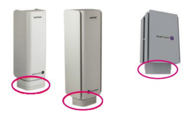
Physical description - external 9764 MCO Wi-Fi AP module
Product overview
The 9764 MCO Wi-Fi AP is housed in a weatherized enclosure containing the following
active components:
•Integrated antennas supporting 2x2 MIMO.
This figure reflects the location of the 9764 MCO Wi-Fi AP when attached to the
technology-specific module (9764 MCO WCDMA module or 9764 MCO LTE module)
of the Alcatel-Lucent 9764 Metro Cell Outdoor, or to the Alcatel-Lucent 9764 Compact
Metro Cell Outdoor.
These 9764 MCO hardware variants are designed to be deployed close to the users,
usually on light poles or on walls of buildings.
Figure C-1 9764 MCO Wi-Fi AP attached to 9764 MCO hardware variants
Installation of the 9764 MCO Wi-Fi AP Physical description - external 9764 MCO Wi-Fi AP module
....................................................................................................................................................................................................................................
....................................................................................................................................................................................................................................
C-2 Alcatel-Lucent – Internal
Proprietary – Use pursuant to Company instruction
9764 CMCO B41 2x6W
3MN-02026-0002-RJZZA
Issue 0.01 April 2015
P
RELIMINARY
P
RELIMINARY
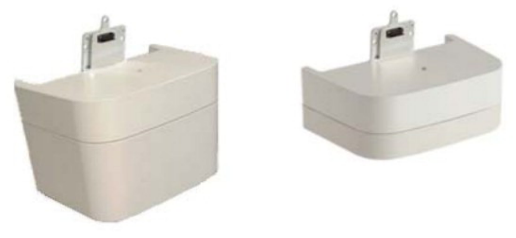
This figure reflects the available 9764 MCO Wi-Fi AP models (9764 Metro Cell Outdoor
Wi-Fi AP V1.0 HG [high gain] and 9764 Metro Cell Outdoor Wi-Fi AP V1.0 MG
[medium gain]).
Figure C-2 9764 MCO Wi-Fi AP - closed housing
Installation of the 9764 MCO Wi-Fi AP Physical description - external 9764 MCO Wi-Fi AP module
....................................................................................................................................................................................................................................
....................................................................................................................................................................................................................................
9764 CMCO B41 2x6W
3MN-02026-0002-RJZZA
Issue 0.01 April 2015
Alcatel-Lucent – Internal
Proprietary – Use pursuant to Company instruction C-3
P
RELIMINARY
P
RELIMINARY
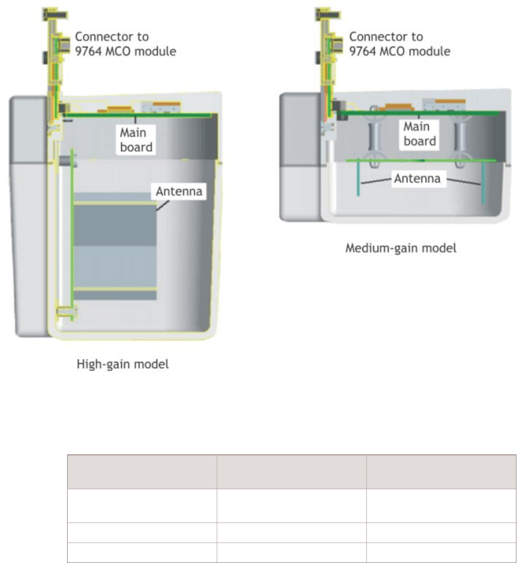
This figure reflects the major components of both the High-gain and Medium-gain
models of the 9764 MCO Wi-Fi AP.
The physical dimensions of the 9764 MCO Wi-Fi AP module are:
Table C-1 9764 MCO Wi-Fi AP physical characteristics
Physical property 9764 MCO Wi-Fi AP V1.0
MG model
9764 MCO Wi-Fi AP V1.0
HG model
Dimension (Height x Width
x Depth)
5cm x 13cm x 7cm 9cm x 13cm x 7cm
Volume 0.5 liters 0.8 liters
Weight 0.35 kg 0.4 kg
Figure C-3 9764 MCO Wi-Fi AP - cutaway view
Installation of the 9764 MCO Wi-Fi AP Physical description - external 9764 MCO Wi-Fi AP module
....................................................................................................................................................................................................................................
....................................................................................................................................................................................................................................
C-4 Alcatel-Lucent – Internal
Proprietary – Use pursuant to Company instruction
9764 CMCO B41 2x6W
3MN-02026-0002-RJZZA
Issue 0.01 April 2015
P
RELIMINARY
P
RELIMINARY
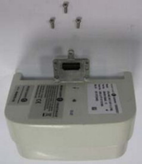
Product base items and configurations
The 9764 MCO Wi-Fi AP module is a single, field-replaceable, unit that may be mounted
to many Alcatel-Lucent 9764 Metro Cell Outdoor variants.
Available models include:
•9764 Metro Cell Outdoor Wi-Fi AP V1.0 HG (contains High-gain integrated
antennas)
•9764 Metro Cell Outdoor Wi-Fi AP V1.0 MG (contains Medium-gain integrated
antennas)
The unit is shipped with three M3 10mm Torx screws used to secure the 9764 MCO
Wi-Fi AP module to the 9764 MCO module.
Connection interfaces
The 9764 MCO Wi-Fi AP module has a single interface connector that plugs into the back
bottom of the technology-specific module (9764 MCO WCDMA module or 9764 MCO
LTE module) of the Alcatel-Lucent 9764 Metro Cell Outdoor or the Alcatel-Lucent 9764
Compact Metro Cell Outdoor, carrying both power and all communication between the
two components.
Installation of the 9764 MCO Wi-Fi AP Physical description - external 9764 MCO Wi-Fi AP module
....................................................................................................................................................................................................................................
....................................................................................................................................................................................................................................
9764 CMCO B41 2x6W
3MN-02026-0002-RJZZA
Issue 0.01 April 2015
Alcatel-Lucent – Internal
Proprietary – Use pursuant to Company instruction C-5
P
RELIMINARY
P
RELIMINARY
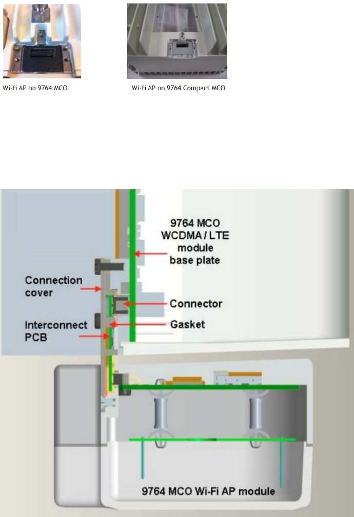
This figure reflects the connection point on the back bottom of the supported 9764 MCO
hardware variants.
This figure provides a cutaway side view of the 9764 MCO Wi-Fi AP module when
connected to a 9764 MCO hardware variant.
Figure C-4 9764 MCO Wi-Fi AP connection point on 9764 MCO
Figure C-5 9764 MCO Wi-Fi AP connected to 9764 MCO (cutaway side view)
Installation of the 9764 MCO Wi-Fi AP Physical description - external 9764 MCO Wi-Fi AP module
....................................................................................................................................................................................................................................
....................................................................................................................................................................................................................................
C-6 Alcatel-Lucent – Internal
Proprietary – Use pursuant to Company instruction
9764 CMCO B41 2x6W
3MN-02026-0002-RJZZA
Issue 0.01 April 2015
P
RELIMINARY
P
RELIMINARY
Antennas
The 9764 MCO Wi-Fi AP supports two integrated antennas optimized for 2x2 MIMO
with up to two spatial streams.
Two hardware models are available:
•9764 MCO Wi-Fi AP V1.0 MG with Medium-gain integrated antennas.
•9764 MCO Wi-Fi AP V1.0 HG with High-gain integrated antennas.
Co-location and interference
For Metro Cells with a fixed integrated antenna and an attached Wi-Fi AP module,
antenna interference is mitigated due to antenna isolation achieved by the hardware
design.
For 9764 Compact Metro Cells using external LTE antennas and an attached Wi-Fi AP
module, antenna interference is mitigated when antenna isolation between the Wi-Fi AP
and the LTE antennas is at least -42 dB.
Status indicators
There is an external single bi-color LED (red/green) on the upper side of the 9764 MCO
Wi-Fi AP housing (pointing up towards the 9764 MCO LTE/WCDMA module radome).
Although external, this LED is not easily visible and is not used for post-installation
troubleshooting. During initial cell power-up, however, the installation technician may
observe the LED changes as the unit goes through its booting sequences. Once the cell is
in normal operation for 30 minutes, the LED will turn off automatically.
Refer to “LED state description - external Wi-Fi AP module” (p. C-13) for details.
The 9764 MCO Wi-Fi AP is monitored/managed remotely at the Alcatel-Lucent 9772
Wi-Fi Service Controller.
Product labeling
To the top of the 9764 MCO Wi-Fi AP will be affixed three labels:
1. A product label reflecting:
•Vendor name/Icon
•Customer ID
•Model name
•Part number
•Lock / Unlock mode icon
Note: The “Unlock” icon applies only to units designated as R&D lab mode.
•Serial number
•MAC address
Installation of the 9764 MCO Wi-Fi AP Physical description - external 9764 MCO Wi-Fi AP module
....................................................................................................................................................................................................................................
....................................................................................................................................................................................................................................
9764 CMCO B41 2x6W
3MN-02026-0002-RJZZA
Issue 0.01 April 2015
Alcatel-Lucent – Internal
Proprietary – Use pursuant to Company instruction C-7
P
RELIMINARY
P
RELIMINARY
•CLEI code (U.S. only)
•Data matrix barcode (2D MicroPDF Symbol) for Part number, Serial number,
MAC address, and CLEI code (CLEI code is for U.S. only)
2. A regulatory label reflecting:
•Vendor name/Icon
•Product name
•Regulatory rules
•Power input
•Enclosure rating
•Applicable regulatory and environmental certification logos (for example, CE and
WEEE recycling logos)
•Manufacturer name
3. (NAR only) An FCC label reflecting:
•Vendor name/Icon
•FCC ID
Installation of the 9764 MCO Wi-Fi AP Physical description - external 9764 MCO Wi-Fi AP module
....................................................................................................................................................................................................................................
....................................................................................................................................................................................................................................
C-8 Alcatel-Lucent – Internal
Proprietary – Use pursuant to Company instruction
9764 CMCO B41 2x6W
3MN-02026-0002-RJZZA
Issue 0.01 April 2015
P
RELIMINARY
P
RELIMINARY
9764 MCO Wi-Fi AP pre-installation information
Product delivery contents
The following items are supplied with the 9764 MCO Wi-Fi AP:
•The 9764 MCO Wi-Fi AP module
•Three M3 10mm Torx screws (to secure the 9764 MCO Wi-Fi AP module to the 9764
MCO module).
Variable parts and ancillary items
In addition to the standard delivered parts, the following variable and ancillary items are
available:
•There are no ancillary parts for the 9764 MCO Wi-Fi AP.
Installation tools required
The following tools may be used during installation:
•Snips
•Screwdrivers (power and/or manual):
– Phillips (flat blade)
– Torx (T10)
Installation of the 9764 MCO Wi-Fi AP 9764 MCO Wi-Fi AP pre-installation information
....................................................................................................................................................................................................................................
....................................................................................................................................................................................................................................
9764 CMCO B41 2x6W
3MN-02026-0002-RJZZA
Issue 0.01 April 2015
Alcatel-Lucent – Internal
Proprietary – Use pursuant to Company instruction C-9
P
RELIMINARY
P
RELIMINARY
Attach 9764 MCO Wi-Fi AP module to 9764 CMCO
Purpose
This topic describes the procedures to attach the 9764 MCO Wi-Fi AP module to the
Alcatel-Lucent 9764 Compact Metro Cell Outdoor.
Prerequisites
Before installation begins, ensure the following:
•T10 Torx screwdriver (power and/or manual) is available.
•Internet service is available.
Attach 9764 MCO Wi-Fi AP module to 9764 CMCO
Perform the following steps to attach the 9764 MCO Wi-Fi AP module to 9764 CMCO:
...................................................................................................................................................................................................
1Remove the 9764 MCO Wi-Fi AP module from its packaging.
...................................................................................................................................................................................................
2Using a T10 Torx screwdriver, remove the cover over the Wi-Fi AP connector on the
lower back of the 9764 CMCO by unscrewing the three screws.
Important! Ensure that the appropriate gasket surrounding the connector is in place
on the 9764 CMCO.
Note: Retain the cover and the three (3) cover screws. Should the need arise to
remove but not replace the 9764 MCO Wi-Fi AP module in the future, the dummy
cover and its screws must be reattached to the 9764 CMCO.
...................................................................................................................................................................................................
3Push the 9764 MCO Wi-Fi AP module onto the Wi-Fi AP connector.
...................................................................................................................................................................................................
4Using a T10 Torx screwdriver and the three M3 10mm Torx screws shipped with the 9764
MCO Wi-Fi AP module, screw the attachment plate to the 9764 CMCO and to the back of
the 9764 MCO Wi-Fi AP module, and tighten all screws.
Torque screws to 0.6 Nm (0.443 lb ft).
Installation of the 9764 MCO Wi-Fi AP Attach 9764 MCO Wi-Fi AP module to 9764 CMCO
....................................................................................................................................................................................................................................
....................................................................................................................................................................................................................................
C-10 Alcatel-Lucent – Internal
Proprietary – Use pursuant to Company instruction
9764 CMCO B41 2x6W
3MN-02026-0002-RJZZA
Issue 0.01 April 2015
P
RELIMINARY
P
RELIMINARY
END OF STEPS
...................................................................................................................................................................................................

9764 MCO Wi-Fi AP integration overview
Integration refers to the entire process from hardware installation to “normal operation”.
9764 MCO Wi-Fi AP integration proceeds as follows:
1. Hardware is installed.
The 9764 MCO Wi-Fi AP module is physically installed on the 9764 CMCO , and the
9764 CMCO is installed and all cabling completed.
2. Power is applied to the 9764 CMCO (and by default, to the 9764 MCO Wi-Fi AP
module).
3. The switch on the 9764 CMCO contains a default configuration that connects the
9764 MCO Wi-Fi AP port to the backhaul port (there are no 9764 MCO Wi-Fi AP
OAM parameters to be configured prior to initial power-up).
The switch will forward Wi-Fi packages as soon as the 9764 CMCO software has
booted and as soon as the 9764 MCO Wi-Fi AP software is running.
4. A connection between 9764 MCO Wi-Fi AP and Alcatel-Lucent 9772 Wi-Fi Service
Controller (9772 Wi-Fi SC) is automatically established.
5. The 9764 MCO Wi-Fi AP downloads the latest software version from the appropriate
file server (if applicable).
6. The 9764 MCO Wi-Fi AP is provisioned and configured via the 9772 Wi-Fi SC.
A 30-minute timer is started after the configuration is sent successfully from the 9772
Wi-Fi SC. During this 30 minutes, the LED on top of the 9764 MCO Wi-Fi AP
module illuminates and is visible through the narrow gap between the bottom of the
9764 MCO and the top of the 9764 MCO Wi-Fi AP module.
For information on the 9772 Wi-Fi SC, refer to the documents listed in the following
table:
Refer to this document At this location For more information on
Alcatel-Lucent 9772 Wi-Fi
Service Controller V1.0 L
Hardware Installation,
3MN-01840-0001- RJZZA
(http://support.alcatel-
lucent.com)
Instructions for installing the
9772 WiSC-L hardware and
accessing its management
interfaces.
Alcatel-Lucent 9764 and
9772 Metro Cell Outdoor
Wi-Fi AP and Wi-Fi Service
Controller, Release WA5.5,
System Reference Guide,
3MN-01840-0002-RKZZA
(http://support.alcatel-
lucent.com)
Instructions for accessing
and using the web-based
graphic user interface (GUI)
to manage/administer the
9772 Wi-Fi Service
Controller and 9764 MCO
Wi-Fi Access Point
Installation of the 9764 MCO Wi-Fi AP Attach 9764 MCO Wi-Fi AP module to 9764 CMCO
....................................................................................................................................................................................................................................
....................................................................................................................................................................................................................................
9764 CMCO B41 2x6W
3MN-02026-0002-RJZZA
Issue 0.01 April 2015
Alcatel-Lucent – Internal
Proprietary – Use pursuant to Company instruction C-11
P
RELIMINARY
P
RELIMINARY

Refer to this document At this location For more information on
Alcatel-Lucent 9764 and
9772, Metro Cell Outdoor
Wi-Fi AP and Wi-Fi Service
Controller, Release WA 5.5,
CLI Reference Guide,
3MN-01840-0003-RKZZA
(http://support.alcatel-
lucent.com)
Instructions for accessing
and using command line
interface (CLI) to
manage/administer the 9772
Wi-Fi Service Controller
and 9764 MCO Wi-Fi
Access Point.
7. The field technician may choose to observe the LED colors and blinking patterns to
ensure error-free boot-up and normal operation. Refer to “LED state description -
external Wi-Fi AP module” (p. C-13) for details.
- If normal operation is achieved, then the LED is automatically turned off when the
30-minute timer expires.
- If there are problems, then the LED displays the applicable error color/pattern. Refer
to “LED state description - external Wi-Fi AP module” (p. C-13) for details.
8. The field technician will make the first test call – provided all necessary core network
elements (NEs) are configured properly (for example, WLAN GW, AAA, etc.).
Installation of the 9764 MCO Wi-Fi AP Attach 9764 MCO Wi-Fi AP module to 9764 CMCO
....................................................................................................................................................................................................................................
....................................................................................................................................................................................................................................
C-12 Alcatel-Lucent – Internal
Proprietary – Use pursuant to Company instruction
9764 CMCO B41 2x6W
3MN-02026-0002-RJZZA
Issue 0.01 April 2015
P
RELIMINARY
P
RELIMINARY

LED state description - external Wi-Fi AP module
Overview
The externally-attached Wi-Fi AP module (supported on some Alcatel-Lucent 9764 Metro
Cell products) has a single external bi-color LED (red/green) on the top of the module
housing. Due to limited visibility requiring direct line-of-site between the Wi-Fi AP
module housing and the host Small Cell housing, the LED is not intended for ongoing
troubleshooting after the unit has been successfully deployed. However, the field
technician installing/replacing the externally-attached Wi-Fi AP module may watch the
LED during boot-up if desired.
The LED illuminates with different colors and blinking patterns during boot-up, then is
automatically turned off after normal operation has been achieved and the 30-minute
timer expires. If there are problems, then the LED displays the applicable error
color/pattern.
LED statuses during boot-up
Tip: In the following table, note that “Slow blinking” refers to an LED blink cycle of
2500 ms on, 2500 ms off; “Fast blinking” refers to an LED blink cycle of 500 ms on,
500 ms off.
After the Wi-Fi AP hardware has been installed, upon power-up the LED reflects Wi-Fi
AP statuses as follows:
Table C-2 Wi-Fi AP LED states during boot-up
Installation /
commissioning
step
Wi-Fi AP State Red LED
segment
Green LED
segment
Combined LED
behavior
1. Power-up with
autotest
BOOTING Solid On Off Solid On (appears red)
2. Wi-Fi AP tries to
get adopted by the
9772 Wi-Fi Service
Controller
ADOPTING Solid On Solid On Solid On (appears
orange)
3. (optional) 9772
Wi-Fi Service
Controller pushes a
software upgrade
UPGRADING Off Solid On Solid On (appears
green)
4. WLANs are
mapped to radios,
normal service
OPERATIONAL Service on 5
GHz: Slow
blinking
Service on 2.4
GHz: Slow
blinking
With both radios
operating: slow orange
blinking
Installation of the 9764 MCO Wi-Fi AP LED state description - external Wi-Fi AP module
....................................................................................................................................................................................................................................
....................................................................................................................................................................................................................................
9764 CMCO B41 2x6W
3MN-02026-0002-RJZZA
Issue 0.01 April 2015
Alcatel-Lucent – Internal
Proprietary – Use pursuant to Company instruction C-13
P
RELIMINARY
P
RELIMINARY

Table C-2 Wi-Fi AP LED states during boot-up (continued)
Installation /
commissioning
step
Wi-Fi AP State Red LED
segment
Green LED
segment
Combined LED
behavior
5. After 30 minutes
in the same state
(Note: the LED
timeout default
setting is 30
minutes, but is
configurable by the
Administrator to
any value from 15
to 1440 minutes.)
HIDING Off Off Off
LED functionality during OPERATIONAL states
The 2 9764 MCO Wi-Fi AP radios are mapped to a color segment of the LED:
•Radio 1 (2.4 GHz) maps to the GREEN segment.
•Radio 2 (5 GHz) maps to the RED segment.
There are 2 factors that affect the LED segment that is associated with each radio:
•If the radio is disabled (shutdown) or not by the administrator (this factor takes
precedence).
•If a WLAN is mapped to the radio, making the radio usable.
If a radio has at least a WLAN mapped to it and it is enabled, then it is operational
(meaning, it will beacon and provide client service).
Tip: In the following tables, note that “Slow blinking” refers to an LED blink cycle of
2500 ms on, 2500 ms off; “Fast blinking” refers to an LED blink cycle of 500 ms on,
500 ms off. An asterisk (*) means that the setting does not matter.
Table C-3 9764 MCO Wi-Fi AP LEDs based on Admin status and WLAN mapping
Radio's Admin status Radio's WLAN mapping LED segment
Disabled * Off
Enabled no WLAN mapped Fast blinking
Enabled WLAN mapped Slow blinking
Installation of the 9764 MCO Wi-Fi AP LED state description - external Wi-Fi AP module
....................................................................................................................................................................................................................................
....................................................................................................................................................................................................................................
C-14 Alcatel-Lucent – Internal
Proprietary – Use pursuant to Company instruction
9764 CMCO B41 2x6W
3MN-02026-0002-RJZZA
Issue 0.01 April 2015
P
RELIMINARY
P
RELIMINARY

Table C-4 9764 MCO Wi-Fi AP LEDs during normal operation states
RADIO 1 / 2.4 GHz / GREEN LED
Segment
RADIO2/5GHz/REDLEDSegment COMBINED
LED
Behavior
Admin
status
WLAN
mapping
Segment
Behavior
Admin
status
WLAN
mapping
Segment
Behavior
Disabled * Off Disabled * Off Off
Enabled no WLAN Fast Disabled * Off Fast Green
WLAN Slow Slow Green
Disabled * Off Enabled no WLAN Fast Fast Red
* WLAN Slow Slow Red
Enabled no WLAN Fast Enabled no WLAN Fast Fast Orange
WLAN Slow WLAN Slow Slow Orange
WLAN Slow no WLAN Fast Fast Red +
Slow Green
(results in a
green/orange/
red pattern)
no WLAN Fast WLAN Slow Slow Red +
Fast Green
(results in a
green/orange/
red pattern)
Installation of the 9764 MCO Wi-Fi AP LED state description - external Wi-Fi AP module
....................................................................................................................................................................................................................................
....................................................................................................................................................................................................................................
9764 CMCO B41 2x6W
3MN-02026-0002-RJZZA
Issue 0.01 April 2015
Alcatel-Lucent – Internal
Proprietary – Use pursuant to Company instruction C-15
P
RELIMINARY
P
RELIMINARY
Installation of the 9764 MCO Wi-Fi AP LED state description - external Wi-Fi AP module
....................................................................................................................................................................................................................................
....................................................................................................................................................................................................................................
C-16 Alcatel-Lucent – Internal
Proprietary – Use pursuant to Company instruction
9764 CMCO B41 2x6W
3MN-02026-0002-RJZZA
Issue 0.01 April 2015
P
RELIMINARY
P
RELIMINARY

Appendix D: Product
conformance statements
Overview
Purpose
This section presents the product conformance statements that apply to the Alcatel-Lucent
Metro Cell Outdoor Access Point equipment when deployed in the United States.
The statements that are required are determined primarily by national or multi-national
regulations. However, in some regions, contract terms determine which statements are
required.
The presence of the statement indicates that the product does comply with that statement
wherever it is required to do so.
Contents
Federal Communications Commission D-2
Product safety conformance statements D-4
Antenna exposure statements D-5
FDA/IEC optical transmitter product compliance statements D-7
Eco-environmental statements D-8
...................................................................................................................................................................................................................................
9764 CMCO B41 2x6W
3MN-02026-0002-RJZZA
Issue 0.01 April 2015
Alcatel-Lucent – Internal
Proprietary – Use pursuant to Company instruction D-1
P
RELIMINARY
P
RELIMINARY

Federal Communications Commission
Federal Communications Commission
Important! Changes or modifications not expressly approved by Alcatel-Lucent, Inc.
could void the user’s authority to operate the equipment.
This device complies with Part 15 of the FCC Rules. Operation is subject to the following
two conditions:
(1) this device may not cause harmful interference, and
(2) this device must accept any interference received, including interference that may
cause undesired operation.
FCC Part 15 Class B
Note: This equipment has been tested and found to comply with the limits for a Class
B digital device, pursuant to Part 15 of the FCC Rules.
These limits are designed to provide reasonable protection against harmful
interference in a residential installation.
This equipment generates, uses, and can radiate radio frequency energy and, if not
installed and used in accordance with the instructions, may cause harmful interference
to radio communications. However, there is no guarantee that interference will not
occur in a particular installation.
If this equipment does cause harmful interference to radio or television reception,
which can be determined by turning the equipment off and on, the user is encouraged
to try to correct the interference by one or more of the following measures:
•Reorient or relocate the receiving antenna
•Increase the separation between the equipment and receiver
•Connect the equipment into an outlet on a circuit different from that to which the
receiver is connected
•Consult the dealer or an experienced radio/TV technician for help.
FCC Part 68
This equipment complies with Part 68 of the FCC rules and the requirements adopted by
the ACTA. At the upper-right-hand corner inside the cabinet assembly of this equipment
is a label that contains, among other information, a product identifier in the format of
AAAEQ##TXXXX. If requested, this number must be provided to the telephone
company.
FIC 04DU9-1SN.
Product conformance statements Federal Communications Commission
....................................................................................................................................................................................................................................
....................................................................................................................................................................................................................................
D-2 Alcatel-Lucent – Internal
Proprietary – Use pursuant to Company instruction
9764 CMCO B41 2x6W
3MN-02026-0002-RJZZA
Issue 0.01 April 2015
P
RELIMINARY
P
RELIMINARY

SOC 6.0N
The T1 network interface on this equipment is hardwired to a punchdown block, which
meets the FCC specifications.
If this equipment causes harm to the telephone network, the telephone company will
notify you in advance that temporary discontinuance of service may be required.
However, if advance notice is not practical, the telephone company will notify the
customer as soon as possible. Also, you will be advised of your right to file a complaint
with the FCC if you believe it is necessary.
The telephone company may make changes in its facilities, equipment, operations, or
procedures that could affect the operation of the equipment. If this happens, the telephone
company will provide advance notice in order for you to make necessary modifications to
maintain uninterrupted service.
FCC regulations prohibit the connection of customer-provided equipment to central office
implemented systems. Connection to party lines is subject to tariffs; users should contact
their state public utility commission, public service commission, or corporation
commission for information.
If the equipment is causing harm to the telephone network, the telephone company may
request that you disconnect the equipment until the problem is resolved.
If trouble is experienced with this equipment repair or warranty information may be
obtained by contacting:
Technical Support Services, within the United States: +1 630 224 4762, prompt 2
RF approval
This equipment complies with Part 2, Subpart J - Equipment Authorization Procedures, of
the FCC Rules.
This device complies with Part 22 – Public Mobile Services, Subpart H – Cellular
Radiotelephone Services.
This equipment complies with Part 24 - Personal Communications Services, Subpart E -
Broadband PCS.
Product conformance statements Federal Communications Commission
....................................................................................................................................................................................................................................
....................................................................................................................................................................................................................................
9764 CMCO B41 2x6W
3MN-02026-0002-RJZZA
Issue 0.01 April 2015
Alcatel-Lucent – Internal
Proprietary – Use pursuant to Company instruction D-3
P
RELIMINARY
P
RELIMINARY
Product safety conformance statements
Product safety conformance
The Alcatel-Lucent 9764 Compact Metro Cell Outdoor B41 2x6W is Safety Certified ITE
by CSA International.
This Certification is marked on the equipment main nameplate label. Should the local
Authority Having Jurisdiction (AHJ) require prior or additional verification of this
Certification, a Product Certificate of Compliance can be obtained from the specific
Certification Body by the Business/Product Unit Applicant for the product or by
contacting:
Technical Support Services, within the United States: +1 630 224 4762, prompt 2
Any modifications to this equipment are not permitted without review and official written
authorization from the specific Certification Body. Unauthorized changes may violate the
Product Safety Certification. Modifications or changes authorized by official CN/CNN
are assumed to have received prior approval from this Lab.
Indoor applications
This equipment is intended for installation in restricted access locations where access is
controlled or where access can only be gained by service personnel with a key or tool.
Access to this equipment is restricted to qualified service personnel only.
Product conformance statements Product safety conformance statements
....................................................................................................................................................................................................................................
....................................................................................................................................................................................................................................
D-4 Alcatel-Lucent – Internal
Proprietary – Use pursuant to Company instruction
9764 CMCO B41 2x6W
3MN-02026-0002-RJZZA
Issue 0.01 April 2015
P
RELIMINARY
P
RELIMINARY
Antenna exposure statements
Antenna exposure
Antenna installations for this equipment shall be performed in accordance with all
applicable manufacturer's recommendations, and national laws and regulations. To ensure
correct antenna installation, the antenna installer shall perform all necessary calculations
and/or field measurements to evaluate compliance with applicable national laws or
regulations regarding exposure to electromagnetic fields. The supplier of radio
equipment, the supplier of antenna equipment and the integrator and builder of the site
must provide sufficient information so that the limits of the exclusion zones can be
determined. Any changes to the antenna or other equipment in the transmit path may
require re-evaluation of the exposures to electromagnetic fields.
Pursuant to 47 CFR Part 1, Subpart I, subject to the provisions of section 1.1307, all
installations must be evaluated for requirements contained in Table 1, “Limits for
maximum permissible exposure,” in section 1.1310.
Guidelines for antenna placements
1. Antennas should be placed more than 20 cm (8 inches) away from possible human RF
exposure.
2. When placing the antennas, please be aware of FCC 47 CFR 1.1307 - 1.1310 and
FCC guidelines for public safety, for example, OET Bulletin No. 56, “Questions and
Answers About the Biological Effects and Potential Hazards of Radio frequency
Electromagnetic Fields” and OET Bulletin 65, “Evaluating Compliance With FCC
Guidelines for Human Exposure to Radiofrequency Electromagnetic Fields”). FCC
requirements mandate maximum power density at location of possible exposure to be
below 0.5 mW/cm2(5 W/m2) at 750 MHz and 1 mW/cm2(10 W/m2) at AWS for
general population/uncontrolled exposure and 2.5 mW/cm2(25 W/m2) at 750 MHz
and 5 mW/cm2(50 W/m2) at AWS for occupational/controlled exposure. Exposure is
averaged over a 30 minute time period for general population and over a 6 minute
time period for occupational/controlled exposure.
Example of a B13 MCO running at 5 W (7 dBW), connected viaa2dBcable loss and
a 3 dBi antenna:
Power density at distance R from antenna is PwD = EIRP(dBW) - 10*log10(4pi*R2)
At 1 m away from the antenna, PwD(1m) = EIRP(7dBw - 2dB + 3dBi) - 11dB =
-3dBw/m2(0.5W/m2)
At 1 ft away from the antenna, PwD(0.305m) = EIRP(8dBW)-0.82dB = 7.18dBW/m2
(5.2W/m2)
Note: Losses of all components between the MCO port and antenna should be
included in EIRP calculations. MCO power in indoor applications may have to be
lowered based on antenna distance to human exposure and total EIRP.
Product conformance statements Antenna exposure statements
....................................................................................................................................................................................................................................
....................................................................................................................................................................................................................................
9764 CMCO B41 2x6W
3MN-02026-0002-RJZZA
Issue 0.01 April 2015
Alcatel-Lucent – Internal
Proprietary – Use pursuant to Company instruction D-5
P
RELIMINARY
P
RELIMINARY
This example indicates that in this particular deployment configuration, US safety limits
for general population are met at a distance slightly over 1 foot for B13 operation.
Product conformance statements Antenna exposure statements
....................................................................................................................................................................................................................................
....................................................................................................................................................................................................................................
D-6 Alcatel-Lucent – Internal
Proprietary – Use pursuant to Company instruction
9764 CMCO B41 2x6W
3MN-02026-0002-RJZZA
Issue 0.01 April 2015
P
RELIMINARY
P
RELIMINARY

FDA/IEC optical transmitter product compliance statements
FDA/IEC optical transmitter product compliance
Alcatel-Lucent declares that this equipment complies with the Food and Drug
Administration’s Center for Devices and Radiological Health (FDA/CDRH) regulations
21 CFR 1040.10 and 1040.11. It is a Class I/1 laser optical fiber communication systems
“product” under the FDA.
This Product is designed to ensure that personnel operating the product are not
endangered by laser radiation during normal operation and fault conditions. This product
does not present a risk of eye injury because it is fully enclosed and does not contain
embedded lasers greater than Class I/1 unless otherwise noted.
Laser warning
WARNING
Laser hazard
The light from laser and high-radiance LED's may cause eye damage if absorbed by the
retina.
•Use of controls or adjustments or performance of procedures other than those
specified herein may result in hazardous laser radiation exposure.
•Do not view directly into the laser beam with optical instruments such as a fiber
microscope because viewing of laser emission in excess of Class 1 limits significantly
increases the risk of eye damage.
•Never look into the end of an exposed fiber or an open connector as long as the
optical source is switched on.
•Ensure that the optical source is switched off before disconnecting optical fiber
connectors.
Product conformance statements FDA/IEC optical transmitter product compliance statements
....................................................................................................................................................................................................................................
....................................................................................................................................................................................................................................
9764 CMCO B41 2x6W
3MN-02026-0002-RJZZA
Issue 0.01 April 2015
Alcatel-Lucent – Internal
Proprietary – Use pursuant to Company instruction D-7
P
RELIMINARY
P
RELIMINARY
Eco-environmental statements
Packaging collection and recovery requirements
Countries, states, localities, or other jurisdictions may require that systems be established
for the return and/or collection of packaging waste from the consumer, or other end user,
or from the waste stream. Additionally, reuse, recovery, and/or recycling targets for the
return and/or collection of the packaging waste may be established.
For more information regarding collection and recovery of packaging and packaging
waste within specific jurisdictions, contact the Alcatel-Lucent Environment, Health and
Safety organization or Alcatel-Lucent Hazardous Waste Center technical support at (888)
539-2783.
For installations not performed by Alcatel-Lucent, please contact the Alcatel-Lucent
Customer Support Center at:
Technical Support Services, within the United States: +1 630 224 4762, prompt 2
Material content compliance
The following notification applies to Alcatel-Lucent products distributed for sale, resale,
or use.
This product, part, or both may include a lithium-manganese dioxide battery, which
contains very small amounts of a perchlorate substance. Special handling may apply.
For California:
Perchlorate Material - special handling may apply.
See http:\\www.dtsc.ca.gov/hazardouswaste/perchlorate/.
Product conformance statements Eco-environmental statements
....................................................................................................................................................................................................................................
....................................................................................................................................................................................................................................
D-8 Alcatel-Lucent – Internal
Proprietary – Use pursuant to Company instruction
9764 CMCO B41 2x6W
3MN-02026-0002-RJZZA
Issue 0.01 April 2015
P
RELIMINARY
P
RELIMINARY
Glossary
...................................................................................................................................................................................................................................
Numerics
3G
Third Generation
3GPP
3rd Generation Partnership Project
...................................................................................................................................................................................................................................
A A (Ampere)
Base SI unit of electrical current.
A-GPS
Assisted Global Positioning System
AC (Alternating Current)
Continuously variable current, rising to a maximum in one direction, falling to zero, then
reversing direction and repeating the cycle in the other direction.
AC convenience outlet
Sites must be equipped with at least two duplex outlets for installation and maintenance
procedures. The outlets are required to power test equipment and installation tools.
ACF (AC Fail)
The AC Fail (ACF) alarm indicates that AC input to one or more rectifiers in the power plant is
absent or outside of the operating range of the equipment
Ambient temperature
The temperature of air or other media in a designated area, particularly the area
ANR
Automatic Neighbor Relation
ANSI (American National Standards Institute)
An organization chartered to accredit standards developed by a wide variety of industry groups,
without influence from any one company or organization. Does not develop standards, but
reviews and implements those developed by other organizations. ANSI is a member of the
International Standards Organization (ISO).
....................................................................................................................................................................................................................................
9764 CMCO B41 2x6W
3MN-02026-0002-RJZZA
Issue 0.01 April 2015
Alcatel-Lucent – Internal
Proprietary – Use pursuant to Company instruction GL-1
P
RELIMINARY
P
RELIMINARY
Antenna
An elevated device for radiating or receiving radio waves. It changes electrical currents into
electromagnetic waves, and vice versa.
AP (Application Processor)
Network element located at the MSC which provides the radio control logic for managing calls.
The AP is a general purpose computer that can host a number of RCS virtual machines.
AWG (American Wire Gauge)
American standard for classifying wire diameter.
...................................................................................................................................................................................................................................
B Backup
Facility used to replace an element which has failed.
Base station
The equipment that provides the air interface that allows mobile terminals to communicate with
the telecommunications network.
Bonding
Permanent connection of metallic parts to form an electrically conductive path that will assure
electrical continuity and have the capability to safely conduct any current likely to be imposed.
Branch circuit
The circuit conductors between the final overcurrent device protecting the circuit and the
outlet(s).
Breaker, circuit
A cut-out device which breaks a circuit when preset limits of current are exceeded.
Buried cable
A communication cable manufactured or produced for the purpose of burial in direct contact with
the earth.
Buried ring ground
A buried, bare, tinned, solid copper cable encircling the site building and/or tower foundation.
Bus bar
One or more conductors that serves as a common connection for a group of related devices.
Busy hour
The uninterrupted period of 60 minutes for which the average intensity of traffic is at maximum.
...................................................................................................................................................................................................................................
C Cable run
Referring to cable routing.
Glossary
....................................................................................................................................................................................................................................
....................................................................................................................................................................................................................................
GL-2 Alcatel-Lucent – Internal
Proprietary – Use pursuant to Company instruction
9764 CMCO B41 2x6W
3MN-02026-0002-RJZZA
Issue 0.01 April 2015
P
RELIMINARY
P
RELIMINARY
Cable sweep
(See Sweep)
CDRH
Center for Devices and Radiological Health
CE
Conformité Européene
A CE Marking on a product is a manufacturer's declaration that the product complies with the
essential requirements of the relevant European health, safety and environmental protection
legislation.
Cell site
An installation located within a cell that houses the equipment needed to set up and complete calls
on a cellular telephone.
CFR
Code of Federal Regulations
Circuit
1. The complete path between two terminals over which one-way or two-way communications
may be provided. 2. An electronic path between two or more points, capable of providing a
number of channels. 3. A number of conductors connected together for the purpose of carrying an
electrical current. 4. An electronic closed-loop path among two or more points used for signal
transfer. 5. A number of electrical components, such as resistors, inductances, capacitors,
transistors, and power sources connected together in one or more closed loops.
CMAS
Commercial Mobile Alert System
CMS
Certificate Management System
Coaxial cable
A cable with one or more coaxial pairs under one outer sheath. The cable consists of a center
conductor surrounded by an insulating material and a concentric outer conductor.
Configuration
An arrangement of functional units according to their nature, number, and chief characteristics.
Controlled environment
An indoor location in which temperature, humidity, and ventilation are maintained at specific
levels.
CPRI
Common Public Radio Interface
CSA (Canadian Standards Association)
Glossary
....................................................................................................................................................................................................................................
....................................................................................................................................................................................................................................
9764 CMCO B41 2x6W
3MN-02026-0002-RJZZA
Issue 0.01 April 2015
Alcatel-Lucent – Internal
Proprietary – Use pursuant to Company instruction GL-3
P
RELIMINARY
P
RELIMINARY
An independent, non-government, not-for-profit association for the development, by consensus,
of Canadian standards and product certifications.
CSC (Cell Site Configuration)
Sheets provided in this document for documenting cell site configuration, conditions, and other
pertinent information for reference during product deployment, and future additions.
...................................................................................................................................................................................................................................
D d2U
digital 2U-height box.
dBi (decibels (dB) relative to isotropic)
Decibels relative to an isotropic antenna gain at radio frequencies.
Antenna gain is usually defined as the ratio of the power produced by the antenna from a far-field
source on the antenna's beam axis to the power produced by a hypothetical lossless isotropic
antenna, which is equally sensitive to signals from all directions. Usually this ratio is expressed in
decibels, and these units are referred to as "decibels-isotropic" (dBi).
DC (Direct Current)
Current flow in one direction.
DHCP
Dynamic Host Configuration Protocol
Diversity
A method of radio transmission and/or reception, which counteracts the effects of fading by
combining several signals all bearing the same information.
DL
downlink
DNS
Domain Name System
DoS
denial of service
Down conductor
A vertical conductor of low impedance that connects the cell site grounding electrode system to
the grounding electrode system.
Driven ground rod
A copper-clad steel or stainless steel rod, a minimum of 2.4 meters (8 feet) long and 5/8 inch in
diameter.
DRX
discontinuous reception
Glossary
....................................................................................................................................................................................................................................
....................................................................................................................................................................................................................................
GL-4 Alcatel-Lucent – Internal
Proprietary – Use pursuant to Company instruction
9764 CMCO B41 2x6W
3MN-02026-0002-RJZZA
Issue 0.01 April 2015
P
RELIMINARY
P
RELIMINARY
...................................................................................................................................................................................................................................
EE1
A four-wire voice and data trunking facility that carries 30 duplex channels in 64-kbps time slices.
E1 facilities are commonly used in countries outside of North America.
Earthquake zone
Seismic ratings ranging from zone 1 (relatively low central office operational shock and vibration
levels) to the most severe zone 4 levels. Equipment must be able to withstand earthquake zone
requirements under both operational and non-operational conditions.
ECID
enhanced cell ID
EIRP
effective isotropic radiated power
Electrolytic ground electrode (rods)
A low resistance grounding rod (pipe) using low resistivity materials.
EMS
Element Management System
ESD
Electrostatic Discharge
EU
European Union
Exothermic weld
A method of making electrical connections of copper to copper or copper to steel using high
temperature fusion. The molten copper flows over conductors in a mold, melting and welding
them together.
...................................................................................................................................................................................................................................
F FA (Fuse Alarm)
The fuse alarm (FA) indicates that the power system battery and load protection fuse opens.
Facility
Any element of physical telephone equipment needed to provide service, such as cables,
switching systems, and microwave radio transmission systems.
FCC (Federal Communications Commission)
A group founded in 1934 to regulate all types of communications in the United States.
Float
To operate a power load on a main-driven rectifier in parallel with a low impedance storage
battery, which is kept fully charged by the rectifier and is itself only called upon to provide power
Glossary
....................................................................................................................................................................................................................................
....................................................................................................................................................................................................................................
9764 CMCO B41 2x6W
3MN-02026-0002-RJZZA
Issue 0.01 April 2015
Alcatel-Lucent – Internal
Proprietary – Use pursuant to Company instruction GL-5
P
RELIMINARY
P
RELIMINARY
during temporary and short-duration peaks for which the rectifier output is insufficient.
FQDN
fully qualified domain name
Frequency
For a periodic wave, such as alternating current, the number of complete cycles per unit of time.
The unit of frequency is cycles per second, or hertz.
FRU
field replaceable unit
Fuse
An overcurrent protective device that has as its critical component a metal wire or strip that will
melt when heated by a prescribed (design) amperage, creating an open in the circuit of which it is
a part, thereby protecting the circuit from an overcurrent condition.
...................................................................................................................................................................................................................................
GGA
general availability
Gain
The ratio of output current, voltage, or power to input current, voltage, or power, respectively.
Gain is usually expressed in dB. If the ratio is less than unity, the gain, expressed in dB, will be
negative, in which case there is a loss between input and output.
Garmin 45XLS
A handheld GPS receiver that can be used to verify GPS reception at a cell site. It has a removable
antenna and provides +5 VDC on the center pin of the RF connection to power external active
antennas. If poor GPS reception is suspected, the Garmin 45XLS can be used to verify that the
GPS antenna and cable system is working acceptably. It will also verify that the GPS antenna
location is acceptable.
GE (Gig-E)
gigabit ethernet
GFCI (Ground Fault Circuit Interrupter)
A device intended for protection of personnel that functions to de-energize a circuit or portion
thereof within an established period of time when a current to ground exceeds some
predetermined value that is less than that required to operate the overcurrent protective device of
the supply circuit.
GPON
Gigabit Passive Optical Network
GPS (Global Positioning System)
A system of 24 satellites that provides, among other things, extremely accurate timing information
to the cell sites.
Glossary
....................................................................................................................................................................................................................................
....................................................................................................................................................................................................................................
GL-6 Alcatel-Lucent – Internal
Proprietary – Use pursuant to Company instruction
9764 CMCO B41 2x6W
3MN-02026-0002-RJZZA
Issue 0.01 April 2015
P
RELIMINARY
P
RELIMINARY
Ground
A conducting connection between equipment or an electrical circuit and earth, or conductive body
that is used in place of earth.
Grounding conductor
A conductor used to connect equipment or a grounded electrical circuit to the grounding electrode
system.
Grounding electrode system
The conductive objects that are intentionally bonded to furnish connection to earth (i.e., buried
ring ground with ground rods, electrically continuous buried metallic water pipe, electrolytic
ground electrode, etc.).
GUI
graphical user interface
Guy
Steel wire or rope used to hold a pole upright.
...................................................................................................................................................................................................................................
H Handoff
A automatic transfer of a cellular telephone call from one cell to another, maintaining call quality
as the mobile user moves through the coverage area.
Heat dissipation
The heat generated by cabinets during operation.
HPBW
half-power beamwidth
HTTP
Hypertext Transfer Protocol
HVAC (Heating, Ventilation, Air Conditioning)
Hz (hertz)
A unit of frequency of a periodic process equal to one cycle per second.
...................................................................................................................................................................................................................................
I IEEE
Institute of Electrical and Electronics Engineers
Indoor site
Installation site in a controlled environment, allowing the use of indoor cabinets.
INTR (Intrusion Alarm)
The Intrusion (INTR) alarm indicates a door or access panel to the power system is open.
Glossary
....................................................................................................................................................................................................................................
....................................................................................................................................................................................................................................
9764 CMCO B41 2x6W
3MN-02026-0002-RJZZA
Issue 0.01 April 2015
Alcatel-Lucent – Internal
Proprietary – Use pursuant to Company instruction GL-7
P
RELIMINARY
P
RELIMINARY
IP
internet protocol
IPsec
internet protocol security
IRC
interference rejection combining
...................................................................................................................................................................................................................................
L LED
light emitting diode
Load
The power consumed by a device or circuit in performing its function.
Loss
The diminution, usually expressed in dB, of signal level in a communications medium. The
power, usually expressed in watts, consumed by a circuit or component. The energy dissipated
without accomplishing useful work or purpose.
LTE
Long Term Evolution
...................................................................................................................................................................................................................................
M MAC (address)
media access control address
A MAC address is a hardware identification number that uniquely identifies each device on a
network.
MAC (protocol)
Medium Access Control Protocol
The media access control (MAC) data communication protocol is a sublayer of the data link layer.
MAC protocol provides addressing and channel access control mechanisms that make it possible
for several terminals or network nodes to communicate within a multiple access network that
incorporates a shared medium, e.g. Ethernet.
MCI
Metro Cell Indoor
MFBI
multiple frequency band indicators
MGB (Main Ground Bus)
A copper bus bar used to provide the electrical interfaces for connection of the isolated ground
plane to the integrated ground system.
Glossary
....................................................................................................................................................................................................................................
....................................................................................................................................................................................................................................
GL-8 Alcatel-Lucent – Internal
Proprietary – Use pursuant to Company instruction
9764 CMCO B41 2x6W
3MN-02026-0002-RJZZA
Issue 0.01 April 2015
P
RELIMINARY
P
RELIMINARY
MHz (Megahertz)
Reference of radio frequency spectrum of one-million cycles.
MIMO
multiple input, multiple output
An antenna technology for wireless communications in which multiple antennas are used at both
the source (transmitter) and the destination (receiver).
MOP (Method of Procedure)
Cell site walk-through where site preparation activities are verified prior to installing the 9412
eNodeB Compact equipment.
MSC (Mobile Switching Center)
In an automatic cellular mobile system, the interface between the radio system and the public
switched telephone network. The MSC performs all signaling functions that are necessary to
establish calls to and from mobile stations.
MSP
mobile service provider
mW
milliWatt
...................................................................................................................................................................................................................................
N NEC (National Electric Code)
Standard that governs the use of electric wire, cable, and fixtures, and electrical and optical
communication cable installed in buildings.
Network
A set of terminals, the communications link that joins them, and the protocols that allow them to
function together and communicate with each other.
NFPA (National Fire Protection Association)
Standards and code writing organization made up of volunteer industrial and institutional
subject-matter-expert committees.
NIU (Network Interface Unit)
A device that performs interface functions, such as code conversion, protocol conversion, and
buffering, required for communications to and from a network. The device is used primarily
within a local area network to allow a number of independent devices, with varying protocols, to
communicate with each other. An NIU converts each device protocol into a common transmission
protocol. The transmission protocol may be chosen to accommodate directly a number of the
devices used within the network without the need for protocol conversion for those devices by the
NIU.
Nominal
Specified value or intended value independent to any uncertainty in its realization. In a device that
realizes a physical quantity, it is the value of such a quantity specified by the manufacturer.
Glossary
....................................................................................................................................................................................................................................
....................................................................................................................................................................................................................................
9764 CMCO B41 2x6W
3MN-02026-0002-RJZZA
Issue 0.01 April 2015
Alcatel-Lucent – Internal
Proprietary – Use pursuant to Company instruction GL-9
P
RELIMINARY
P
RELIMINARY
Non-Alcatel-Lucent power
3rd party power systems, or power systems other than Alcatel-Lucent.
...................................................................................................................................................................................................................................
O OA&M
operations, administration, and maintenance
OLCS
Online Customer Support
OOT
out of time alignment
OSP
Outside Plant
OSS
Operation Support System
OTDOA
observed time difference of arrival
...................................................................................................................................................................................................................................
P Pair cable
Cable made up of one or more separately insulated wire pairs, none of which is arranged with
another quads.
PCI
physical cell ID
PDU
Power Distribution Unit
Phase
The number of separate voltage waves in commercial alternating current, designated as "single
phase", "three phase", etc.
Pigtail
A short length of electrical conductor permanently affixed to a component, used to connect the
component to another.
PMJ
Conditions that impacts service of the power system and/or requires immediate attention are
classified as major alarms and designated as Power Major (PMJ) alarms.
Glossary
....................................................................................................................................................................................................................................
....................................................................................................................................................................................................................................
GL-10 Alcatel-Lucent – Internal
Proprietary – Use pursuant to Company instruction
9764 CMCO B41 2x6W
3MN-02026-0002-RJZZA
Issue 0.01 April 2015
P
RELIMINARY
P
RELIMINARY
PMN
Conditions requiring service, but having no immediate impact on the power system output are
classified as minor alarms and designated as Power Minor (PMN) alarms.
PnP
plug and play
PVC (Polyvinyl Chloride)
A thermoplastic made of polymers, which is tough, nonflammable, and water resistant and is used
as an insulation.
...................................................................................................................................................................................................................................
Q QoE
Quality Of Experience
QoS
quality of service
...................................................................................................................................................................................................................................
R RAN
Radio Access Network
Receive-only
Pertaining to a device or a mode of operation capable of receiving messages, but not transmitting
messages.
RF (Radio Frequency)
Electromagnetic wave used for, among other things, cellular voice and data communications.
RMS (Root Mean Square)
Effective value of an alternative wave. For AC, this is numerically equal to DC value of the
current with the same heating effect.
RoHS
Restriction of Hazardous Substances
Rx (RX)
Receive
...................................................................................................................................................................................................................................
S Sector
The coverage area within the degree of directionality of the antennas.
SeGW
Security Gateway
Glossary
....................................................................................................................................................................................................................................
....................................................................................................................................................................................................................................
9764 CMCO B41 2x6W
3MN-02026-0002-RJZZA
Issue 0.01 April 2015
Alcatel-Lucent – Internal
Proprietary – Use pursuant to Company instruction GL-11
P
RELIMINARY
P
RELIMINARY
Service provider
Customer who purchases switching and Site equipment from system vendors, which, in turn, is
provided to end-user subscribers through resellers and distribution channels.
SFP (Small Form-Factor Pluggable)
A compact, hot-pluggable transceiver that interfaces a network device motherboard to a
fiber-optic or copper networking cable to support telecommunication and data communications.
Shield
A housing, screen, sheath, or cover that substantially reduces the coupling of electric, magnetic, or
electromagnetic fields into or out of circuits or transmission lines.
Short-term
No more than 96 consecutive hours or 15 days per year.
Single-phase
A circuit in which there is only one sinusoidal voltage variation.
Site
An installation that houses the equipment needed to set up and complete calls on a cellular
telephone.
Site preparation
To perform the requirements necessary at the site before installation can begin.
SON
Self-Organizing Network
Stranded
Wires twisted together to form a strong flexible cable.
Surge protector
Protective device used to limit surge voltages by discharging or bypassing any unwanted surge
current that may enter a building or equipment.
Sweep
To vary the frequency of a signal over a whole band as a means of checking the response of
equipment under test.
...................................................................................................................................................................................................................................
TT1
A four-wire voice and data trunking facility that carries 24 duplex channels over 56-kbps time
slots.
THHN (Thermoplastic high-heat resistant nylon-coated)
Glossary
....................................................................................................................................................................................................................................
....................................................................................................................................................................................................................................
GL-12 Alcatel-Lucent – Internal
Proprietary – Use pursuant to Company instruction
9764 CMCO B41 2x6W
3MN-02026-0002-RJZZA
Issue 0.01 April 2015
P
RELIMINARY
P
RELIMINARY
Three-phase
An alternating current supply with three sinusoidal voltages differing in phase by 120°.
THWN (Thermoplastic heat and water resistant nylon-coated)
TRDU (Transmit Receive Duplex Unit)
Twisted pair cable
Cable made up of one or more separately insulated twisted-wire pairs, none of which is arranged
with another to form quads.
Tx (TX)
Transmit
TYP (Typical)
...................................................................................................................................................................................................................................
U UBC
Uniform Building Code
UL
uplink
UL® (Underwriters Laboratories)
Laboratories that test and approve materials and equipment against predetermined performance
standards.
UV (Ultraviolet)
The portion of the electromagnetic spectrum in which the longest wavelength is just below the
visible spectrum, extending from approximately 4 nm to approximately 400 nm. Some authorities
place the lower limit of uv at values between 1 and 40 nm, 1 nm being the upper wavelength limit
of x-rays. The 400-nm limit is the lowest visible wavelength, i.e., the highest visible frequency,
violet.
...................................................................................................................................................................................................................................
V V (Volt)
The derived SI unit of electrical potential difference. It is the difference in potential between two
points of a conducting wire carrying a constant current of 1 ampere when the power dissipated
between these two points is equal to 1 watt.
Vac (Volts Alternating Current)
VDC (Volts Direct Current)
VoLTE
Voice over LTE
Glossary
....................................................................................................................................................................................................................................
....................................................................................................................................................................................................................................
9764 CMCO B41 2x6W
3MN-02026-0002-RJZZA
Issue 0.01 April 2015
Alcatel-Lucent – Internal
Proprietary – Use pursuant to Company instruction GL-13
P
RELIMINARY
P
RELIMINARY
VPN
Virtual Private Network
Vrms (Volts Root Mean Square)
VSWR (Voltage Standing Wave Ratio)
In a transmission line, the ratio of maximum to minimum voltage in a standing wave pattern. The
VSWR is a measure of impedance mismatch between the transmission line and its load. The
higher the VSWR, the greater the mismatch. The minimum VSWR, i.e., that which corresponds to
a perfect impedance match, is unity.
...................................................................................................................................................................................................................................
W W (watts)
The derived SI unit of power. It is equivalent to 1 joule per second, or 1 volt-ampere.
Walk-through
A critical examination of a design or product undertaken to ensure that it is of adequate quality.
Waveform
The characteristic shape of a periodic wave, determined by the frequencies present and their
amplitudes and relative phases.
WCDMA
Wideband Code Division Multiple Access
WEEE
Waste Electrical and Electronic Equipment
WMM (9471 WMM)
The Alcatel-Lucent 9471 Wireless Mobility Manager (WMM) is the Serving GPRS Support Node
and Mobility Management Entity (SGSN/MME) in the converged wireless packet core network. It
performs mobility and session management signaling and packet data switching for GSM,
WCDMA and LTE access networks.
WPS
Wireless Provisioning System
Glossary
....................................................................................................................................................................................................................................
....................................................................................................................................................................................................................................
GL-14 Alcatel-Lucent – Internal
Proprietary – Use pursuant to Company instruction
9764 CMCO B41 2x6W
3MN-02026-0002-RJZZA
Issue 0.01 April 2015
P
RELIMINARY
P
RELIMINARY
Index
Numerics
9764 CMCO
grounding, 5-2
Standard pole mount, 4-19
.............................................................
Aabout this document
document support, xv
glossary, GL-1
how to order, xv
technical support, xv
additional optional items
Wi-Fi AP, C-9
Antenna
GPS/GLONASS antenna, 2-9
RF antenna, 2-9
AWG conversion table, xiii
.............................................................
BBackhaul, 2-8
Basic site requirements
Installation clearances, 3-4
.............................................................
Ccabling, 5-12
Cabling
Ethernet, 4-3,4-6,4-9,4-11
cabling
ground, 5-2
Cabling
RF antenna (external), 5-4
SFP transceiver module, 4-3,
4-9
Connect electrical Ethernet cable,
4-6,4-11
Connect GPS antenna, 5-8
Connect optical Ethernet cable,
4-6,4-11
Connectors
Metro Radio Module, 2-6
Conventions used, xii
.............................................................
DDaisy chaining, 4-3,4-3,4-6,4-9,
4-9,4-11
configuration options, 3-9
Device placement, 3-2
Dimensions and weights, 2-11
document support contact
information, xv
.............................................................
FFinal installation activities and
checks, 6-2
.............................................................
Gglossary, GL-1
grounding
9764 CMCO, 5-2
.............................................................
HHardware and ancillary items
9764 CMCO base items, 2-14
9764 MCO Wi-Fi AP, 2-14
Backhaul modules, 2-16
Electrical Ethernet cable –
Specifications, 2-18
Ethernet cable (electrical),
2-17
Ethernet cable (optical), 2-18
External antenna - GPS, 2-17
Grounding, 2-16
Installation kits, 2-15
Power, 2-15
RF antenna, 2-16
SFP modules, 2-16
Solar shield, 2-19
Surge arrestor, 2-17
how to order documents, xv
.............................................................
IInstallation kits
for pole mount, 3-5
for wall mount, 3-7
Installation materials, 3-2
....................................................................................................................................................................................................................................
9764 CMCO B41 2x6W
3MN-02026-0002-RJZZA
Issue 0.01 April 2015
Alcatel-Lucent – Internal
Proprietary – Use pursuant to Company instruction IN-1
P
RELIMINARY
P
RELIMINARY
Intended audience, xi
.............................................................
LLED state description, B-1
LED status
external Wi-Fi AP module,
C-13
.............................................................
MMain characteristics, 2-2
MCO
Standard wall mount, 4-33
Metro Cell Module
status indicators, 2-10
Metro Cell Outdoor
Backhaul, 2-8
GPS antenna, 2-9
product labelling, 2-10
RF antenna, 2-9
Metro Dock cabling
mount the surge arrestor, 4-15
Metro Dock Indoor
tools, 3-3
Metro Radio Module
connectors, 2-6
Metro Radio Outdoor
physical description, 2-4
power supply, 2-8
.............................................................
PPhysical description
external 9764 MCO Wi-Fi AP
module, C-2
Metro Radio Outdoor, 2-4
Physical description (external
Wi-Fi AP module)
Antennas, C-7
Connection interfaces, C-5
Product base items and
configurations, C-5
Product labeling, C-7
Product overview, C-2
Status indicators, C-7
Pole mount
installation kits, 3-5
options, 3-5
Power cord, connect, 5-13,5-14
Power supply
Metro Radio Outdoor, 2-8
Pre-installation, 3-2
pre-installation
Wi-Fi AP, C-9
Product capabilities, 2-2
product conformance statements,
D-1
Product delivery contents, 3-2
product delivery contents
Wi-Fi AP, C-9
product labeling, C-7
product labelling, 2-10
.............................................................
RReason for revision, xi
Related documentation
Alcatel-Lucent, xiv
third party, xiv
Related training, xiv
.............................................................
Ssafety information, xv
SFP transceiver module, 4-3,4-9
Standard pole mount, 4-19
Standard wall mount, 4-33
status indicators, 2-10
Supported installation options
Daisy chain, 2-13
Standard, 2-12
Street furniture, 2-14
Systems supported, xiv
.............................................................
Ttechnical support contact
information, xv
Tools, 3-3
tools
Wi-Fi AP, C-9
.............................................................
WWall mount, 4-38
examples, 3-8
installation kits, 3-7
options, 3-7
Weights and dimensions, 2-11
Wi-Fi AP, C-1
additional optional items, C-9
attach to MCO, C-10
installation, C-10
pre-installation, C-9
product delivery contents, C-9
tools, C-9
Wire cross-sectional area table,
xiii
Wire size table, xiii
with optional tilt brackets, 4-38
Index
....................................................................................................................................................................................................................................
....................................................................................................................................................................................................................................
IN-2 Alcatel-Lucent – Internal
Proprietary – Use pursuant to Company instruction
9764 CMCO B41 2x6W
3MN-02026-0002-RJZZA
Issue 0.01 April 2015
P
RELIMINARY
P
RELIMINARY