Alien Technology B2450R01 Frequency Hopping Tag Identification Reader User Manual 299798
Alien Technology Corporation Frequency Hopping Tag Identification Reader 299798
Contents
- 1. Quick Installation Guide
- 2. Quick Reference Guide
- 3. User Guide Part 1
- 4. User Guide Part 2
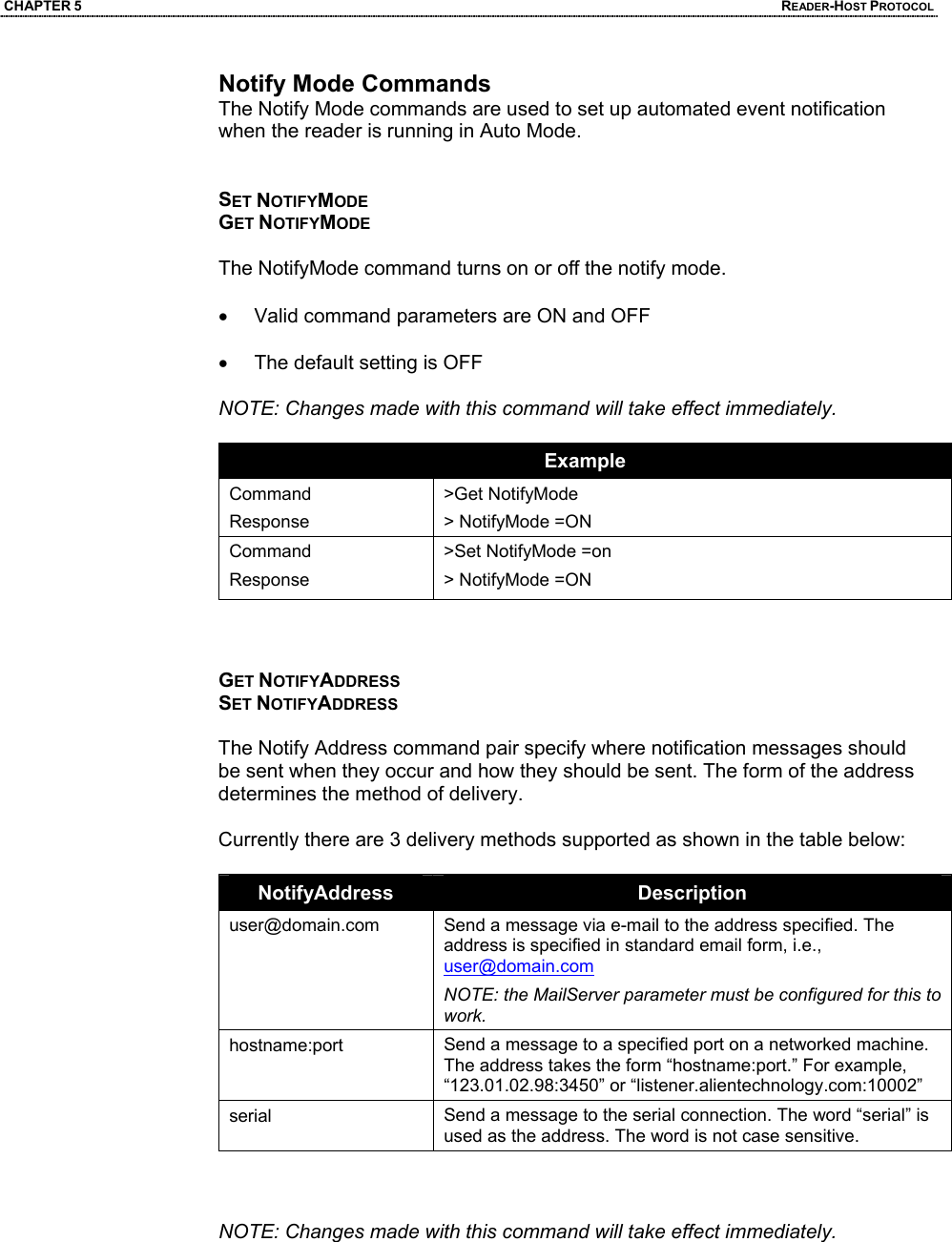
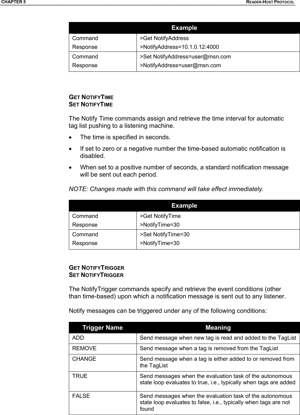
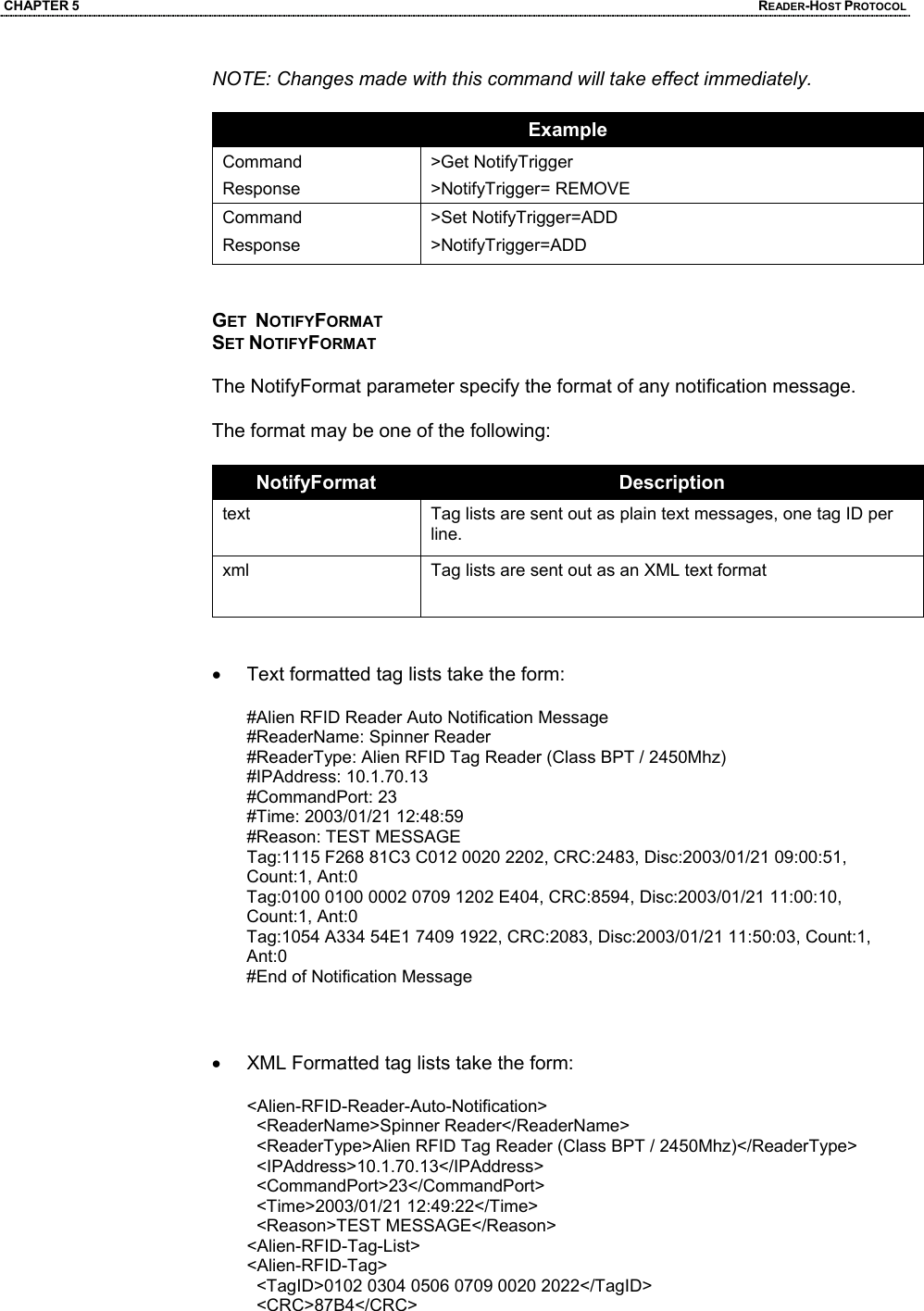
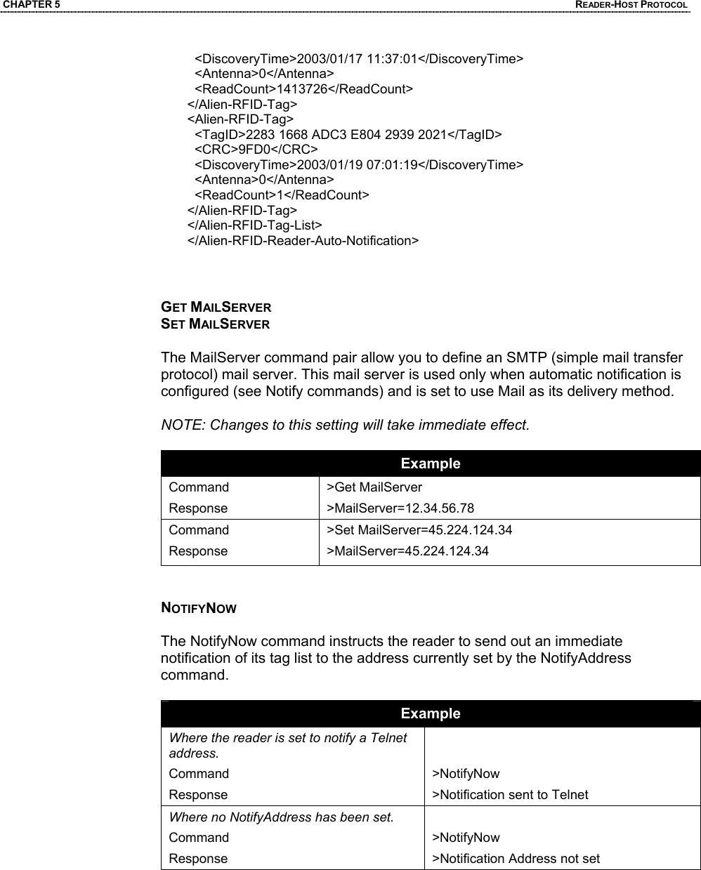
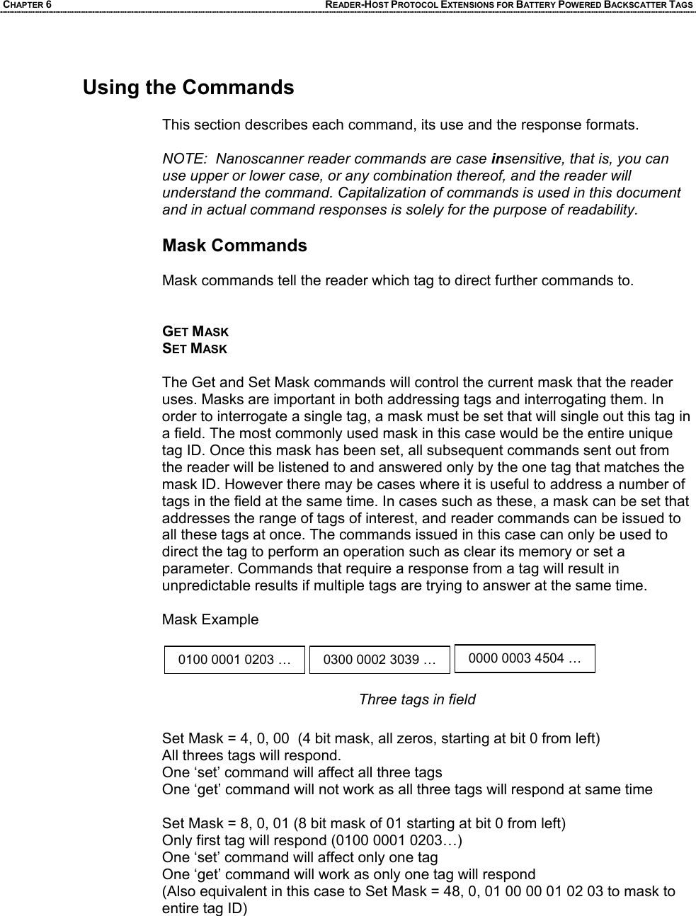
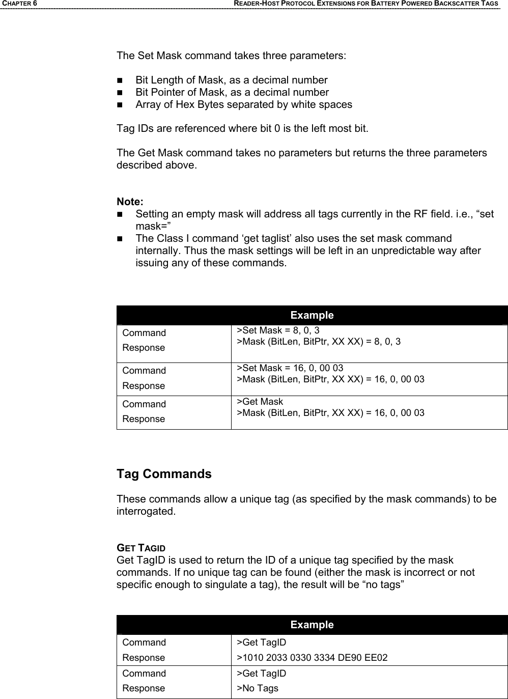
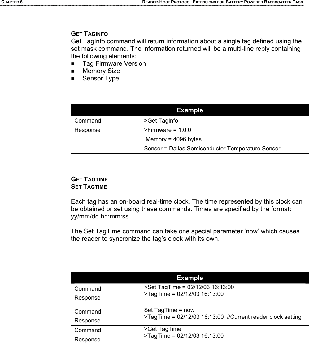
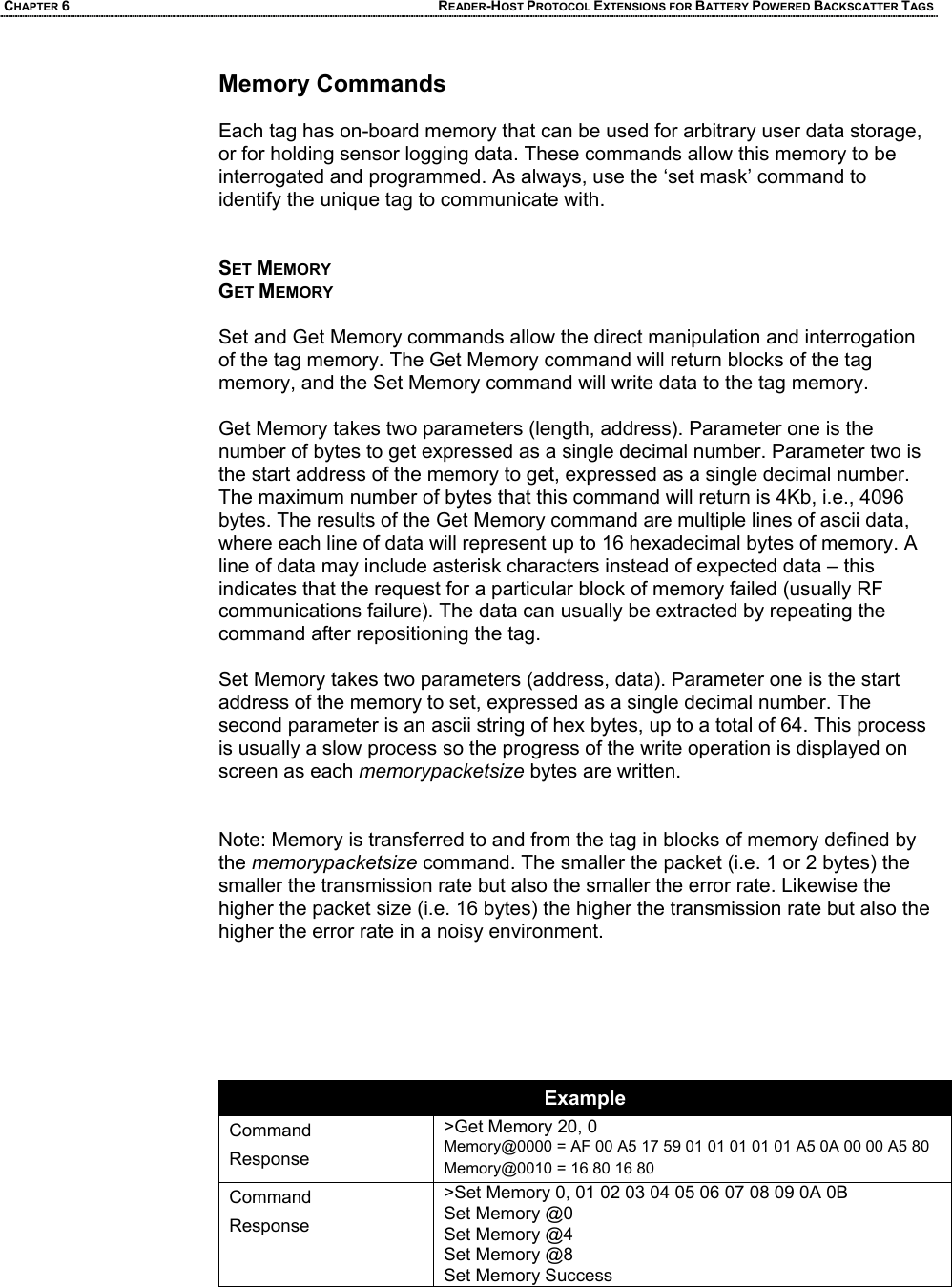
User Guide Part 2