Alien Technology B2450R01 Frequency Hopping Tag Identification Reader User Manual 299798
Alien Technology Corporation Frequency Hopping Tag Identification Reader 299798
Contents
- 1. Quick Installation Guide
- 2. Quick Reference Guide
- 3. User Guide Part 1
- 4. User Guide Part 2
User Guide Part 2

CHAPTER 5 READER-HOST PROTOCOL
Time Commands – Text Based
The time at which tags are read by a reader is particularly important for many
applications. For this reason, the reader has three time commands to ensure that
the onboard real-time clock is always set accurately.
GET TIME
SET TIME
These commands allow the current time to be assigned to or retrieved from the
reader.
• Times used by this command are always specified in local time, as defined
by the TimeZone command.
• Times are always specified by the format YYYY/MM/DD hh:mm:ss.
NOTE: Changes made with this command will take effect immediately.
Example
Command
Response
>Get Time
>Time = 2002/6/3 9:23:01
>Set Time = 2002/6/3 19:23:01
>Time = 2002/6/3 19:23:01
GET TIMEZONE
SET TIMEZONE
These commands allow the current time zone to be assigned to or retrieved from
the reader. The time zone specifies the number of hours that must be added to or
subtracted from UTC (Coordinated Universal Time; also known as GMT or Zulu)
to determine a local time reference.
For example, to convert from UTC to Pacific Standard Time, set the TimeZone to
–8. To convert from UTC to Pacific Daylight Time, set the TimeZone to –7.
• The default setting for this command is -7 hours (Pacific Daylight Time)
because PDT is UTC time minus 7 hours.
• For more information about time zones, servers and UTC, refer to the
Website listed under the Get/Set TimeServer command.
The TimeZone parameter is only useful if the TimeServer is used to automatically
set the system clock. In this case, the TimeServer always retrieves the time in
UTC format and will need to be offset to reflect local time using this parameter.
NOTE: Changes made with this command will take effect immediately.
2450MHz
Battery

CHAPTER 5 READER-HOST PROTOCOL
Example
Command
Response
>Get TimeZone
>TimeZone = -8
>Set TimeZone = 3
>TimeZone = 3
GET TIMESERVER
SET TIMESERVER
The reader uses the Internet to accurately set its internal clock every time it is
rebooted. The protocol it uses is called the Daytime Protocol (RFC-867) which
typically returns the time in UTC format.
In order to use this feature, a TimeServer must be specified. This is the network
address of a machine that is constantly running the Daytime Protocol. In the US
there are a number of machines owned and operated by the Government
explicitly providing the time and date to Internet users.
• By default the reader is configured to connect to one of these machines on
boot-up to get the current time.
• For a more in-depth description of this server, and a list of other publicly
accessible Daytime Protocol Servers, see:
http://www.boulder.nist.gov/timefreq/service/its.htm
• The default setting for this command is 132.163.4.101, a primary NIST
network time server. Some alternative time servers are:
time-a.nist.gov / 129.6.15.28
time-b.nist.gov / 129.6.15.29
time.nist.gov / 192.43.244.18
NOTE: After making changes with this command, you must reboot the reader to
implement the changes.
Example
Command
Response
>Get TimeServer
>TimeServer = 129.6.15.28
>Set TimeServer = 129.6.15.28
>TimeServer = 129.6.15.28
The TimeServer is only used once when the reader is booted up. A message in
the boot sequence (sent out to the serial console) indicates success or failure of
this option.
For example, a successful boot sequence will report the following messages to
the serial console:
Booting Alien RFID Reader
Boot> Boot Level 1 (Console Communication) : Success
Boot> Boot Level 2 (Reader Communication) : Success
Boot> Boot Level 3 (Tag Manager) : Memory for 1000 Tags
CHAPTER 5 READER-HOST PROTOCOL
Boot> Boot Level 4 (System Settings) : Success
Boot> Boot Level 5 (Network) : Success - IP Address is 10.1.60.4
Boot> Boot Level 6 (Telnet Interface) : Success - Port 23 Ready
Boot> Boot Level 7 (Web Interface) : Success
Boot> Boot Level 8 (Network Time Service) : Success - Time Set to
2002/08/23 16:50:24
Boot> Ready
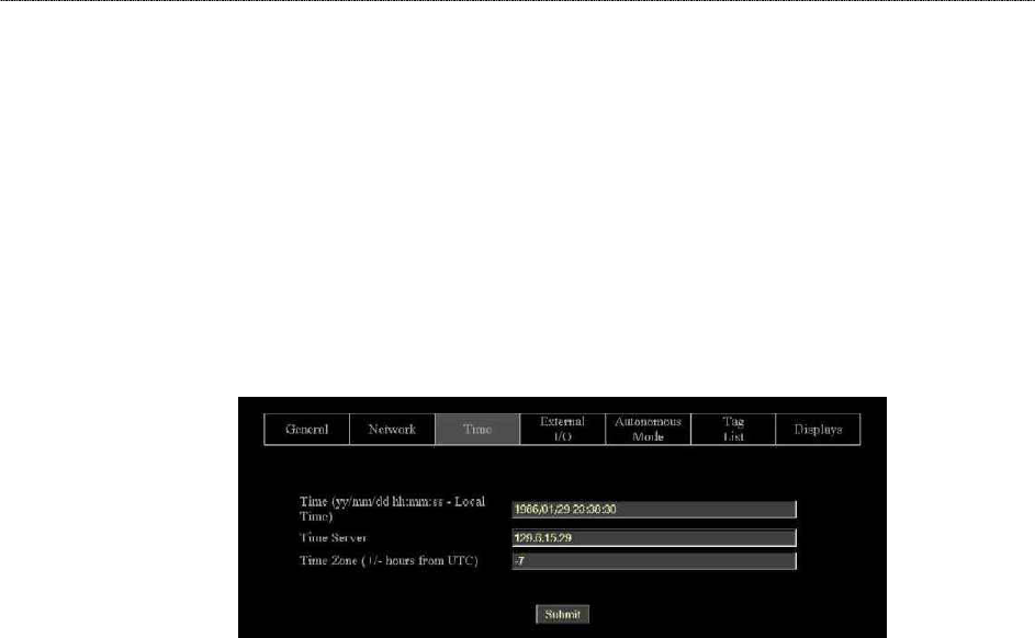
Time Commands – Web Based
Time commands are issued via the Web page to set up and access reader time
parameters.
COMMANDS/OPERATIONS VIA WEB TIME TAB
Command equivalents found on the Web-based “Time” tab are:
• Get | Set Time
• Get | Set TimeZone
• Get | Set TimeServer
Web view Time
tab covers all
Get and Set
time
commands.

CHAPTER 5 READER-HOST PROTOCOL
External I/O Commands
These commands allow you to configure and retrieve current data regarding the
reader’s external output functions.
SET EXTERNALOUTPUT
GET EXTERNALOUTPUT
The reader controls four external output pins, which can subsequently be used to
control external devices such a doors/gates, security lights. etc. Please refer to
Chapter 1, Specifications section in this document for pinout diagrams.
With this command you can set the external output pin values. The command
takes a single parameter that represents the bit mask settings of the external
pins.
• Bit 0 represents the state of pin 0, and Bit 1 represents the state of pin 1, Bit
2 is state of pin 2 and Bit 3 is state of pin 3.
For example, to set pin 1 to high and pin 0 on low, use the bit mask of
10binary which translates to 2decimal
NOTE: Changes made with this command will take effect immediately.
Example
Command
Response
>Set ExternalOuput = 2
>ExternalOutput = 2
Command
Response
>Get ExternalOuput
>ExternalOutput = 2
GET EXTERNALINPUT
The reader also monitors four external input pins, which can subsequently be
controlled by external proximity detectors and other input devices such as
“magic-eyes” and magnetic switches. This command allows these external input
pin values to be obtained.Please refer to Chapter 1, Specifications section in this
document for pinout diagrams.
• The command returns a single byte result that represents the bit mask
settings of the external pins. Bit 0 represents the state of pin 0, and Bit 1
represents the state of pin 1, Bit 2 is state of pin 2 and Bit 3 is state of pin 3.
NOTE: Changes made with this command will take effect immediately.
Example
Command
Response
>Get ExternalInput
>ExternalInput = 2 (i.e., binary 10)
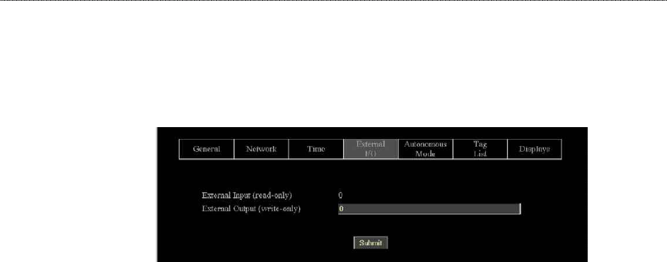
CHAPTER 5 READER-HOST PROTOCOL
External I/O Commands – Web Based
Time commands are issued via the Web page to set up and access external
input and output parameters.
COMMANDS/OPERATIONS ON WEB EXTERNAL I/O TAB
Command equivalents found on the Web-based “External I/O” tab are:
• Get | Set ExternalOutput
• Get ExternalInput
Web view I/O
tab covers all
Get and Set
External I/O
commands.

CHAPTER 5 READER-HOST PROTOCOL
Tag List Commands – Command Line
Tag list commands allow you to retrieve immediate listings of tags that have been
read and saved by the reader, and to assign and retrieve tag list functional
parameters.
NOTE: Web versions of these operations are shown in the next section.
GET TAGLIST (N)
You can retrieve the reader’s stored tag list either a single time (Get TagList) or
multiple times (Get TagList n).
• The maximum number of tags that can be stored in the tag list is 1000.
Using the Get TagList to retrieve the stored list only once:
• If the reader is currently in interactive mode, the reader will immediately
perform a full tag search (read and report) and display its current internal tag
list. The reply will be a multi-line command with each line listing an active tag.
If the tag list is empty, the message “(No Tags)” will be returned.
• If the reader is in Autonomous mode, the reader will display its current
internal tag list only.
Using the Get TagList with an optional integer ‘n’ instructs the command to be
repeated ‘n’ times before a combined result is returned.
The format of the data returned by this command is specified using the Set
TagListFormat command, described below.
Example
Command
Response
Get TagList
Tag: 0002 0030 A233 0400 0000 1023, CRC: B340, Disc:
2002/03/23 15:36:33, Count: 4, Ant: 0
Tag: 8080 AAAB ECF0 0000 125E 0102, CRC: 3021, Disc:
2002/03/22 12:26:01, Count: 3, Ant: 1
Command
Response
Get TagList
(No Tags)
SET TAGLISTFORMAT
GET TAGLISTFORMAT
The Get and Set TagListFormat commands specify the formatting of tag lists.
The command itself takes a text string as its argument, and can be one of the
following:
The format may be one of the following:

CHAPTER 5 READER-HOST PROTOCOL
TagListFormat Description
text
Tag lists displayed as plain text messages, one tag ID per line.
xml Tag lists are displayed in XML text format
• Text formatted tag lists take the following from:
Tag:1115 F268 81C3 C012 0000 1E45, CRC:2483, Disc:2003/01/21 09:00:51,
Count:1, Ant:0
Tag:0100 0100 0002 0709 0303 5752, CRC:8594, Disc:2003/01/21 11:00:10,
Count:1, Ant:0
Tag:1054 A334 54E1 7409 A434 8972, CRC:2083, Disc:2003/01/21 11:50:03,
Count:1, Ant:0
• XML Formatted tag lists take the form:
<Alien-RFID-Tag-List>
<Alien-RFID-Tag>
<TagID>0102 0304 0506 0709 0020 2020</TagID>
<CRC>87B4</CRC>
<DiscoveryTime>2003/01/17 11:37:01</DiscoveryTime>
<Antenna>0</Antenna>
<ReadCount>1413726</ReadCount>
</Alien-RFID-Tag>
<Alien-RFID-Tag>
<TagID>2283 1668 ADC3 E804 3403 3030</TagID>
<CRC>9FD0</CRC>
<DiscoveryTime>2003/01/19 07:01:19</DiscoveryTime>
<Antenna>0</Antenna>
<ReadCount>1</ReadCount>
</Alien-RFID-Tag>
</Alien-RFID-Tag-List>
In all cases the following information is reported per tag:
• TagID: The 96 bit tag ID.
• CRC: The checksum built into the tag that guarantees that the tagID was
read correctly.
• Disc: The time the tag was first read by the reader in the current session.
• Count: The number of times the tag has been read in the current session.
• Ant: The antenna port number that the tag was LAST seen at.
Example
Command
Response
Set TagListFormat = XML
TagListFormat = XML
Command
Response
Get TagListFormat
TagListFormat = Text
NOTE: Changes made with this command will take effect immediately.

CHAPTER 5 READER-HOST PROTOCOL
SET ACQUIREMODE
GET ACQUIREMODE
Whenever the reader is called upon to read a tag it does so using the current
AcquireMode. Currently the allowable modes are as follows:
AcquireMode Description
Inventory
Perform full inventory of multiple tags.
Global Scroll Perform fast search for single tag.
The default setting is Inventory
• Inventory Mode
The Inventory acquire mode performs a full anti-collision search on tags in
the reader’s field of view. This method will locate and distinguish multiple
tags infront of the reader at the same time.
• Global Scroll Mode
The Global Scroll acquire mode instructs the reader to read a single tag
repeatedly. This is a very fast tag reading method which is most effective
when only one tag at a time is expected to be within reader range, as in
conveyor belt applications. Under such circumstances, the performance for
single tag reading is considerably faster than repeatedly doing a full tag
search using the Inventory mode.
NOTE: If multiple tags are in range of the reader when this mode is used, the
reader will either select one of the tags (usually the “strongest’” or “loudest”)
to read and report, or will read none of the tags.
NOTE: Changes made with this command will take effect immediately.
CLEAR TAGLIST
The Clear TagList command instructs the reader to immediately clear its internal
tag list.
Example
Command
Response
>Clear TagList
>Tag List has been reset!
NOTE: Changes made with this command will take effect immediately.

CHAPTER 5 READER-HOST PROTOCOL
GET PERSISTTIME
SET PERSISTTIME
The PersistTime specifies the length of time a tag’s data will remain in the
reader’s internal list of active tags.
• Persist times are specified in seconds.
• The default setting is 10 seconds.
• Setting the persist time to a positive number (1-n) will establish a persist time
of the desired number of seconds
• A zero persist time (0) will guarantee that tags are not stored in the tag list.
However issuing a get taglist command in interactive mode will return any
tags immediately found even though they won’t be stored in the taglist.
• Setting the persist time to –1 will cause the history to build indefinitely until a
get taglist command is issued; at this point the tag list is returned, and then
immediately cleared.
The maximum number of tags that can be stored in the tag list is 1000. Once this
tag limit is reached, error messages will be reported to the serial console, and no
new tags will be added to the list until room is available.
NOTE: Changes made with this command will take effect immediately.
Example
Command
Response
>Get PersistTime
>PersistTime=10
Command
Response
>Set PersistTime=300
>PersistTime=10
CHAPTER 5 READER-HOST PROTOCOL
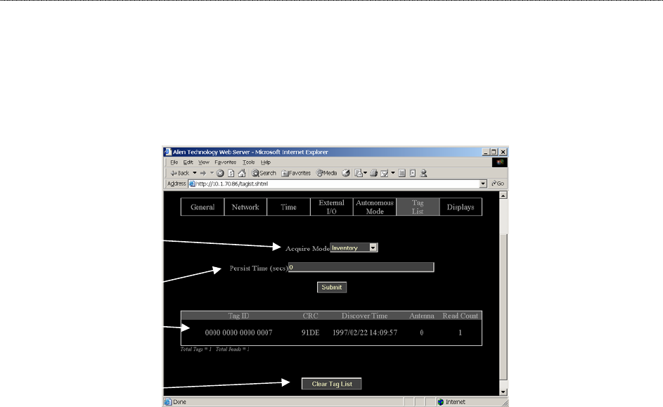
Tag List Commands – Web Based
Tag List commands are issued via the Web page to set up and access tag
information.
COMMANDS/OPERATIONS ON WEB TAG LIST TAB
NOTE : Every time the Tag List page is loaded / refreshed, it is the equivalent of
issuing a Get Taglist command to the reader. The results are displayed on the
page.
Command equivalents found on the Web-based “Tag List” tab are:
• Get | Set AcquireMode
• Get | Set PersistTime
• Get TagList(n)
Includes tag ID, crc, discover time, reading antenna and read count.
• Clear Taglist
Tag List displays:
• Tag ID
• CRC
• Discover time
• Reading
Antenna
• Read count
Allows you to:
Get and Set
Acquire
Mode…
Get and Set
Persist Time...
Display
TagList...
and
Clear TagList.

CHAPTER 5 READER-HOST PROTOCOL
Autonomous Mode Commands
Autonomous mode is a multi-stage configuration and operation mode that
enables hands-free monitoring of tags.
• The first stage requires you to issue a series of configuration commands to
the reader. These commands detail how and when to read tags, and then
when tags are found, who to tell.
• Once configured, the reader can be left to operate on its own.
For a detailed description of the Automonous mode system please refer to
Chaprer 4 of this guide.
SET AUTOMODE
GET AUTOMODE
The AutoMode command turns on or off the automode.
• Valid command parameters are ON and OFF
• The default setting is OFF
NOTE: Changes made with this command will take effect immediately.
Example
Command
Response
>Get AutoMode
>AutoMode=ON
Command
Response
>Set AutoMode=on
>AutoMode=ON
SET AUTOWAITOUTPUT
GET AUTOWAITOUTPUT
The AutoWaitOutput specifies the output pin settings to effect while in the wait
state of autonomous mode. The parameter is a bit mask for the four external
output pins, where a ‘1’ sets a pin to high, and a ‘0’ sets a pin to low. Pin 1 is
specified by bit one in the mask, and Pin 0 is specified by bit zero in the mask
etc…
NOTE: Changes made with this command will take effect immediately.
Example
Command
Response
>Get AutoWaitOutput
> AutoWaitOutput =0
Command
Response
>Set AutoWaitOutput =3 //Turn pins 0 and 1 to high
> AutoWaitOutput =3

CHAPTER 5 READER-HOST PROTOCOL
SET AUTOSTARTTRIGGER
GET AUTOSTARTTRIGGER
The AutoStartTrigger specifies the external input pins to monitor to cause the
automode to jump from wait state to work state. Triggers can either be a pin
going from low to high (rising edge) to high to low (falling edge). For each type of
change, an integer bit mask must be provided to specify the pins to listen for
changes on.
The command takes two parameters, a rising edge bit mask and a falling edge
bit mask.
NOTE: Changes made with this command will take effect immediately.
Example
Command
Response
>Get AutoStartTrigger
> AutoStartTrigger(rising, falling)= 0, 0
Command
Response
>Set AutoStartTrigger =3, 0 //Listen for rising edges on pins 0
and 1
> AutoStartTrigger (rising, falling)= 3, 0
SET AUTOWORKOUTPUT
GET AUTOWORKOUTPUT
The AutoWorkOutput specifies the output pin settings to effect while in the work
state of autonomous mode. The parameter is a bit mask for the four external
output pins, where a ‘1’ sets a pin to high, and a ‘0’ sets a pin to low. Pin 1 is
specified by bit one in the mask, and Pin 0 is specified by bit zero in the mask
etc…
NOTE: Changes made with this command will take effect immediately.
Example
Command
Response
>Get AutoWorkOutput
> AutoWorkOutput =0
Command
Response
>Set AutoWorkOutput =3 //Turn pins 0 and 1 to high
> AutoWorkOutput =3
SET AUTOACTION
GET AUTOACTION
The AutoAction command specifies the action to perform when running in the
work mode of auto mode. This can be one of the following options:
AutoAction Description
Acquire
Perform an acquire action, as specified by the AcquireMode
options.

CHAPTER 5 READER-HOST PROTOCOL
• The default setting is Acquire
NOTE: Changes made with this command will take effect immediately.
Example
Command
Response
>Get AutoAction
> AutoAction = Acquire
Command
Response
>Set AutoAction =Acquire
> AutoAction = Acquire
SET AUTOSTOPTRIGGER
GET AUTOSTOPTRIGGER
The AutoStopTrigger specifies the external input pins to monitor to cause the
automode to jump from work state to evaluate state. Triggers can either be a pin
going from low to high (rising edge) to high to low (falling edge). For each type of
change, an integer bit mask must be provided to specify the pins to listen for
changes on.
The command takes two parameters, a rising edge bit mask and a falling edge
bit mask.
NOTE: Changes made with this command will take effect immediately.
Example
Command
Response
>Get AutoStopTrigger
> AutoStopTrigger(rising, falling)= 0, 0
Command
Response
>Set AutoStopTrigger =3, 0 //Listen for rising edges on pins 0
and 1
> AutoStopTrigger (rising, falling)= 3, 0
SET AUTOSTOPTIMER
GET AUTOSTOPTIMER
The AutoStopTimer offers an alternative way to jump from work state to evaluate
state. This is a time based jump, that will happen after the timer period specified
by this command expires. The parameter is a single time period, specified in
milliseconds.
NOTE: Changes made with this command will take effect immediately.

CHAPTER 5 READER-HOST PROTOCOL
Example
Command
Response
>Get AutoStopTimer
> AutoStopTrimer (ms) = 0
Command
Response
>Set AutoStopTimer =1000 //Acquire for 1sec then evaluate
> AutoStopTimer (ms)= 1000
SET AUTOTRUEOUTPUT
GET AUTOTRUEOUTPUT
The AutoTrueOutput specifies the output pin settings to effect if the evaluate
mode of autonomous mode evaluates to true. The parameter is a bit mask for the
four external output pins, where a ‘1’ sets a pin to high, and a ‘0’ sets a pin to
low. Pin 1 is specified by bit one in the mask, and Pin 0 is specified by bit zero in
the mask etc…
NOTE: Changes made with this command will take effect immediately.
Example
Command
Response
>Get AutoTrueOutput
> AutoTrueOutput =0
Command
Response
>Set AutoTrueOutput =3 //Turn pins 0 and 1 to high
> AutoTrueOutput =3
SET AUTOTRUEPAUSE
GET AUTOTRUEPAUSE
The AutoTruePause specifies a millisecond pause to effect if the autonomous
evaluation mode evaluates to true. This pause will occur after the
AutoTrueOutput command has been processed.
NOTE: Changes made with this command will take effect immediately.
Example
Command
Response
>Get AutoTruePause
> AutoTruePause (ms)=0
Command
Response
>Set AutoTruePause =500 //Pause for half a sec.
> AutoTruePause = 500
SET AUTOFALSEOUTPUT
GET AUTOFALSEOUTPUT
The AutoFalseOutput specifies the output pin settings to effect if the evaluate
mode of autonomous mode evaluates to false. The parameter is a bit mask for
the four external output pins, where a ‘1’ sets a pin to high, and a ‘0’ sets a pin to

CHAPTER 5 READER-HOST PROTOCOL
low. Pin 1 is specified by bit one in the mask, and Pin 0 is specified by bit zero in
the mask etc…
NOTE: Changes made with this command will take effect immediately.
Example
Command
Response
>Get AutoFalseOutput
> AutoFalseOutput =0
Command
Response
>Set AutoFalseOutput =3 //Turn pins 0 and 1 to high
> AutoFalseOutput =3
SET AUTOFALSEPAUSE
GET AUTOFALSEPAUSE
The AutoFalsePause specifies a millisecond pause to effect if the autonomous
evaluation mode evaluates to false. This pause will occur after the
AutoFalseOutput command has been processed.
NOTE: Changes made with this command will take effect immediately.
Example
Command
Response
>Get AutoFalsePause
> AutoFalsePause (ms)=0
Command
Response
>Set AutoFalsePause =500 //Pause for half a sec.
> AutoFalsePause = 500
AUTOMODERESET
The AutoModeReset command will reset all auto mode parameters to their
default values, including setting the auto mode to off.
NOTE: Changes made with this command will take effect immediately.
Example
Command
Response
>AutoModeReset
> All AutoMode settings have been reset !
CHAPTER 5 READER-HOST PROTOCOL
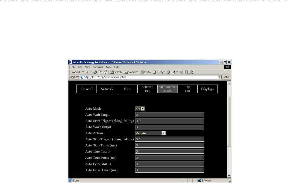
Autonomous Mode Commands – Web Based
Autonomous Mode commands are issued via the Web page to set up and access
autonomous mode parameters.
COMMANDS/OPERATIONS ON WEB AUTONOMOUS MODE TAB
Command equivalents found on the Web-based “Autonomous Mode” tab are:
• Get | Set AutoMode
• Get | Set AutoWaitOutput
• Get | Set AutoStartTrigger
• Get | Set AutoWorkOutput
• Get | Set AutoAction
• Get | Set AutoStopTrigger
• Get | Set AutoStopTimer
• Get | Set AutoTrueOutput
• Get | Set AutoTruePause
• Get | Set AutoFalseOutput
• Get | Set AutoFalsePause
Web view
Autonomous Mode
tab covers all Get
and Set
autonomous mode
commands.

CHAPTER 5 READER-HOST PROTOCOL
Notify Mode Commands
The Notify Mode commands are used to set up automated event notification
when the reader is running in Auto Mode.
SET NOTIFYMODE
GET NOTIFYMODE
The NotifyMode command turns on or off the notify mode.
• Valid command parameters are ON and OFF
• The default setting is OFF
NOTE: Changes made with this command will take effect immediately.
Example
Command
Response
>Get NotifyMode
> NotifyMode =ON
Command
Response
>Set NotifyMode =on
> NotifyMode =ON
GET NOTIFYADDRESS
SET NOTIFYADDRESS
The Notify Address command pair specify where notification messages should
be sent when they occur and how they should be sent. The form of the address
determines the method of delivery.
Currently there are 3 delivery methods supported as shown in the table below:
NotifyAddress Description
user@domain.com
Send a message via e-mail to the address specified. The
address is specified in standard email form, i.e.,
user@domain.com
NOTE: the MailServer parameter must be configured for this to
work.
hostname:port Send a message to a specified port on a networked machine.
The address takes the form “hostname:port.” For example,
“123.01.02.98:3450” or “listener.alientechnology.com:10002”
serial Send a message to the serial connection. The word “serial” is
used as the address. The word is not case sensitive.
NOTE: Changes made with this command will take effect immediately.

CHAPTER 5 READER-HOST PROTOCOL
Example
Command
Response
>Get NotifyAddress
>NotifyAddress=10.1.0.12:4000
Command
Response
>Set NotifyAddress=user@msn.com
>NotifyAddress=user@msn.com
GET NOTIFYTIME
SET NOTIFYTIME
The Notify Time commands assign and retrieve the time interval for automatic
tag list pushing to a listening machine.
• The time is specified in seconds.
• If set to zero or a negative number the time-based automatic notification is
disabled.
• When set to a positive number of seconds, a standard notification message
will be sent out each period.
NOTE: Changes made with this command will take effect immediately.
Example
Command
Response
>Get NotifyTime
>NotifyTime=30
Command
Response
>Set NotifyTime=30
>NotifyTime=30
GET NOTIFYTRIGGER
SET NOTIFYTRIGGER
The NotifyTrigger commands specify and retrieve the event conditions (other
than time-based) upon which a notification message is sent out to any listener.
Notify messages can be triggered under any of the following conditions:
Trigger Name Meaning
ADD Send message when new tag is read and added to the TagList
REMOVE Send message when a tag is removed from the TagList
CHANGE Send message when a tag is either added to or removed from
the TagList
TRUE Send messages when the evaluation task of the autonomous
state loop evaluates to true, i.e., typically when tags are added
FALSE Send messages when the evaluation task of the autonomous
state loop evaluates to false, i.e., typically when tags are not
found

CHAPTER 5 READER-HOST PROTOCOL
NOTE: Changes made with this command will take effect immediately.
Example
Command
Response
>Get NotifyTrigger
>NotifyTrigger= REMOVE
Command
Response
>Set NotifyTrigger=ADD
>NotifyTrigger=ADD
GET NOTIFYFORMAT
SET NOTIFYFORMAT
The NotifyFormat parameter specify the format of any notification message.
The format may be one of the following:
NotifyFormat Description
text
Tag lists are sent out as plain text messages, one tag ID per
line.
xml Tag lists are sent out as an XML text format
• Text formatted tag lists take the form:
#Alien RFID Reader Auto Notification Message
#ReaderName: Spinner Reader
#ReaderType: Alien RFID Tag Reader (Class BPT / 2450Mhz)
#IPAddress: 10.1.70.13
#CommandPort: 23
#Time: 2003/01/21 12:48:59
#Reason: TEST MESSAGE
Tag:1115 F268 81C3 C012 0020 2202, CRC:2483, Disc:2003/01/21 09:00:51,
Count:1, Ant:0
Tag:0100 0100 0002 0709 1202 E404, CRC:8594, Disc:2003/01/21 11:00:10,
Count:1, Ant:0
Tag:1054 A334 54E1 7409 1922, CRC:2083, Disc:2003/01/21 11:50:03, Count:1,
Ant:0
#End of Notification Message
• XML Formatted tag lists take the form:
<Alien-RFID-Reader-Auto-Notification>
<ReaderName>Spinner Reader</ReaderName>
<ReaderType>Alien RFID Tag Reader (Class BPT / 2450Mhz)</ReaderType>
<IPAddress>10.1.70.13</IPAddress>
<CommandPort>23</CommandPort>
<Time>2003/01/21 12:49:22</Time>
<Reason>TEST MESSAGE</Reason>
<Alien-RFID-Tag-List>
<Alien-RFID-Tag>
<TagID>0102 0304 0506 0709 0020 2022</TagID>
<CRC>87B4</CRC>

CHAPTER 5 READER-HOST PROTOCOL
<DiscoveryTime>2003/01/17 11:37:01</DiscoveryTime>
<Antenna>0</Antenna>
<ReadCount>1413726</ReadCount>
</Alien-RFID-Tag>
<Alien-RFID-Tag>
<TagID>2283 1668 ADC3 E804 2939 2021</TagID>
<CRC>9FD0</CRC>
<DiscoveryTime>2003/01/19 07:01:19</DiscoveryTime>
<Antenna>0</Antenna>
<ReadCount>1</ReadCount>
</Alien-RFID-Tag>
</Alien-RFID-Tag-List>
</Alien-RFID-Reader-Auto-Notification>
GET MAILSERVER
SET MAILSERVER
The MailServer command pair allow you to define an SMTP (simple mail transfer
protocol) mail server. This mail server is used only when automatic notification is
configured (see Notify commands) and is set to use Mail as its delivery method.
NOTE: Changes to this setting will take immediate effect.
Example
Command
Response
>Get MailServer
>MailServer=12.34.56.78
Command
Response
>Set MailServer=45.224.124.34
>MailServer=45.224.124.34
NOTIFYNOW
The NotifyNow command instructs the reader to send out an immediate
notification of its tag list to the address currently set by the NotifyAddress
command.
Example
Where the reader is set to notify a Telnet
address.
Command
Response
>NotifyNow
>Notification sent to Telnet
Where no NotifyAddress has been set.
Command
Response
>NotifyNow
>Notification Address not set
CHAPTER 5 READER-HOST PROTOCOL
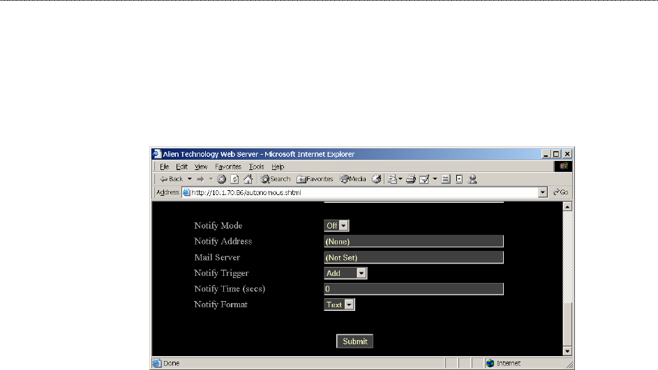
Notify Mode Commands – Web Based
Notify Mode commands are issued via the Web page to set up and access notify
mode parameters. The commands are accessed at the bottom of the
Autonomous Web Page section.
COMMANDS/OPERATIONS ON WEB AUTONOMOUS MODE TAB
Command equivalents found on the Web-based “Autonomous Mode” tab are:
• Get | Set NotifyMode
• Get | Set NotifyAddress
• Get | Set MailServer
• Get | Set NotifyTrigger
• Get | Set NotifyTime
• Get | Set NotifyFormat
Web view Notify
Mode tab covers all
Get and Set notify
mode commands.
This web page is
located at the
bottom of the
Autonomous Mode
web page.

CHAPTER 6 READER-HOST PROTOCOL EXTENSIONS FOR BATTERY POWERED BACKSCATTER TAGS
CHAPTER 6
ReaderÙHost Protocol Extensions for Battery
Powered Backscatter Tags
The Reader <–> Host protocol detailed in Chapter 5 is a text-based
communications protocol for configuring and operating the entire family of Alien
Nanoscanner RFID readers. This chapter details extensions to this standard
protocol that directly address the extended functionality of the Battery Powered
Backscatter tags running at 2450Mhz.
Introduction
The Battery Powered Backscatter readers fully support the Class I protocol as
described in chapter 5 of this document. In addition to the basic Class I
command set, these readers also support extra commands especially designed
to address the enhanced functionality of the Battery Powered Backscatter tags.
These extra commands fall into one of five categories:
Masks
All commands aimed at Battery Powered Backscatter tags require the setting of a
mask, which directs the commands only at the tags who’s ID matches the mask.
This mechanism allows commands to be sent to one specific tag, a selective
group of tags or the whole field of tags.
Tags
The tag commands are used to explicitly communicate with a tag, to either
interrogate its features and functionality, or its ID.
Memory
The Battery Powered Backscatter tags support a read-write on-board memory
typically in the range of 4K bytes to 16K bytes. The memory commands
described in this document allow the tag memory to be read and written in
discrete blocks via RF communication.
Sensors
The Battery Powered Backscatter tags can optionally support the use of on-
board sensors such as temperature or vibration sensors. The sensor commands
can be used to interrogate and control the use of these on-board devices.
Logging
If a tag is equipped with one or more sensors, they can be instructed to
autonomously log data to tag memory even in the absence of an RF field. The
logging commands are the interface to this functionality.

CHAPTER 6 READER-HOST PROTOCOL EXTENSIONS FOR BATTERY POWERED BACKSCATTER TAGS
Command Summaries
Command List
Mask Commands
• Get | Set Mask
Tag Commands
• Get TagID
• Get TagInfo
• Get | Set TagTime
Memory Commands
• Get | Set Memory
• Get | Set MemoryPacketSize
• Clear Memory
Sensor Commands
• Get SensorValue
Logging Commands
• Get | Set LoggingMode
• Get | Set LoggingInterval

CHAPTER 6 READER-HOST PROTOCOL EXTENSIONS FOR BATTERY POWERED BACKSCATTER TAGS
Command List with Functions
MASK COMMANDS
Command Description
Get Mask
Set Mask
Get and Set the current mask as an array of bytes
TAG COMMANDS
Command Description
Get TagID Get the ID of a tag
Get TagInfo Get information about a tag
Get TagTime
Set TagTime
Get and Set the time and date on the tag’s built in
clock
MEMORY COMMANDS
Command Description
Get Memory
Set Memory
Get and Set data from the tag memory
Get MemoryPacketSize
Set MemoryPacketSize
Get and Set the size of the memory packets used in
get and set memory commands
Clear Memory Clear the tag memory
SENSOR COMMANDS
Command Description
Get SensorValue
Get the current value from a tag’s sensor
LOGGING COMMANDS
Command Description
Get LoggingMode
Set LoggingMode
Get and Set the automatic logging mode
Get LoggingInterval
Set LoggingInterval
Set and Get the interval between automatic log
recording events

CHAPTER 6 READER-HOST PROTOCOL EXTENSIONS FOR BATTERY POWERED BACKSCATTER TAGS
Using the Commands
This section describes each command, its use and the response formats.
NOTE: Nanoscanner reader commands are case insensitive, that is, you can
use upper or lower case, or any combination thereof, and the reader will
understand the command. Capitalization of commands is used in this document
and in actual command responses is solely for the purpose of readability.
Mask Commands
Mask commands tell the reader which tag to direct further commands to.
GET MASK
SET MASK
The Get and Set Mask commands will control the current mask that the reader
uses. Masks are important in both addressing tags and interrogating them. In
order to interrogate a single tag, a mask must be set that will single out this tag in
a field. The most commonly used mask in this case would be the entire unique
tag ID. Once this mask has been set, all subsequent commands sent out from
the reader will be listened to and answered only by the one tag that matches the
mask ID. However there may be cases where it is useful to address a number of
tags in the field at the same time. In cases such as these, a mask can be set that
addresses the range of tags of interest, and reader commands can be issued to
all these tags at once. The commands issued in this case can only be used to
direct the tag to perform an operation such as clear its memory or set a
parameter. Commands that require a response from a tag will result in
unpredictable results if multiple tags are trying to answer at the same time.
Mask Example
Set Mask = 4, 0, 00 (4 bit mask, all zeros, starting at bit 0 from left)
All threes tags will respond.
One ‘set’ command will affect all three tags
One ‘get’ command will not work as all three tags will respond at same time
Set Mask = 8, 0, 01 (8 bit mask of 01 starting at bit 0 from left)
Only first tag will respond (0100 0001 0203…)
One ‘set’ command will affect only one tag
One ‘get’ command will work as only one tag will respond
(Also equivalent in this case to Set Mask = 48, 0, 01 00 00 01 02 03 to mask to
entire tag ID)
0100 0001 0203 … 0300 0002 3039 … 0000 0003 4504 …
Three tags in field

CHAPTER 6 READER-HOST PROTOCOL EXTENSIONS FOR BATTERY POWERED BACKSCATTER TAGS
The Set Mask command takes three parameters:
Bit Length of Mask, as a decimal number
Bit Pointer of Mask, as a decimal number
Array of Hex Bytes separated by white spaces
Tag IDs are referenced where bit 0 is the left most bit.
The Get Mask command takes no parameters but returns the three parameters
described above.
Note:
Setting an empty mask will address all tags currently in the RF field. i.e., “set
mask=”
The Class I command ‘get taglist’ also uses the set mask command
internally. Thus the mask settings will be left in an unpredictable way after
issuing any of these commands.
Example
Command
Response
>Set Mask = 8, 0, 3
>Mask (BitLen, BitPtr, XX XX) = 8, 0, 3
Command
Response
>Set Mask = 16, 0, 00 03
>Mask (BitLen, BitPtr, XX XX) = 16, 0, 00 03
Command
Response
>Get Mask
>Mask (BitLen, BitPtr, XX XX) = 16, 0, 00 03
Tag Commands
These commands allow a unique tag (as specified by the mask commands) to be
interrogated.
GET TAGID
Get TagID is used to return the ID of a unique tag specified by the mask
commands. If no unique tag can be found (either the mask is incorrect or not
specific enough to singulate a tag), the result will be “no tags”
Example
Command
Response
>Get TagID
>1010 2033 0330 3334 DE90 EE02
Command
Response
>Get TagID
>No Tags

CHAPTER 6 READER-HOST PROTOCOL EXTENSIONS FOR BATTERY POWERED BACKSCATTER TAGS
GET TAGINFO
Get TagInfo command will return information about a single tag defined using the
set mask command. The information returned will be a multi-line reply containing
the following elements:
Tag Firmware Version
Memory Size
Sensor Type
Example
Command
Response
>Get TagInfo
>Firmware = 1.0.0
Memory = 4096 bytes
Sensor = Dallas Semiconductor Temperature Sensor
GET TAGTIME
SET TAGTIME
Each tag has an on-board real-time clock. The time represented by this clock can
be obtained or set using these commands. Times are specified by the format:
yy/mm/dd hh:mm:ss
The Set TagTime command can take one special parameter ‘now’ which causes
the reader to syncronize the tag’s clock with its own.
Example
Command
Response
>Set TagTime = 02/12/03 16:13:00
>TagTime = 02/12/03 16:13:00
Command
Response
Set TagTime = now
>TagTime = 02/12/03 16:13:00 //Current reader clock setting
Command
Response
>Get TagTime
>TagTime = 02/12/03 16:13:00

CHAPTER 6 READER-HOST PROTOCOL EXTENSIONS FOR BATTERY POWERED BACKSCATTER TAGS
Memory Commands
Each tag has on-board memory that can be used for arbitrary user data storage,
or for holding sensor logging data. These commands allow this memory to be
interrogated and programmed. As always, use the ‘set mask’ command to
identify the unique tag to communicate with.
SET MEMORY
GET MEMORY
Set and Get Memory commands allow the direct manipulation and interrogation
of the tag memory. The Get Memory command will return blocks of the tag
memory, and the Set Memory command will write data to the tag memory.
Get Memory takes two parameters (length, address). Parameter one is the
number of bytes to get expressed as a single decimal number. Parameter two is
the start address of the memory to get, expressed as a single decimal number.
The maximum number of bytes that this command will return is 4Kb, i.e., 4096
bytes. The results of the Get Memory command are multiple lines of ascii data,
where each line of data will represent up to 16 hexadecimal bytes of memory. A
line of data may include asterisk characters instead of expected data – this
indicates that the request for a particular block of memory failed (usually RF
communications failure). The data can usually be extracted by repeating the
command after repositioning the tag.
Set Memory takes two parameters (address, data). Parameter one is the start
address of the memory to set, expressed as a single decimal number. The
second parameter is an ascii string of hex bytes, up to a total of 64. This process
is usually a slow process so the progress of the write operation is displayed on
screen as each memorypacketsize bytes are written.
Note: Memory is transferred to and from the tag in blocks of memory defined by
the memorypacketsize command. The smaller the packet (i.e. 1 or 2 bytes) the
smaller the transmission rate but also the smaller the error rate. Likewise the
higher the packet size (i.e. 16 bytes) the higher the transmission rate but also the
higher the error rate in a noisy environment.
Example
Command
Response
>Get Memory 20, 0
Memory@0000 = AF 00 A5 17 59 01 01 01 01 01 A5 0A 00 00 A5 80
Memory@0010 = 16 80 16 80
Command
Response
>Set Memory 0, 01 02 03 04 05 06 07 08 09 0A 0B
Set Memory @0
Set Memory @4
Set Memory @8
Set Memory Success

CHAPTER 6 READER-HOST PROTOCOL EXTENSIONS FOR BATTERY POWERED BACKSCATTER TAGS
SET MEMORYPACKETSIZE
GET MEMORYPACKETSIZE
Set and Get MemoryPacketSize commands determine the number of bytes to
use in each memory related transmission packet to and from the tag.
The smaller the packet (i.e. 1 or 2 bytes) the smaller the transmission rate but
also the smaller the error rate. Likewise the higher the packet size (i.e. 16 bytes)
the higher the transmission rate but also the higher the error rate in a noisy
environment.
The default setting for this value is 16 bytes. The allowable range is 1 to 16
bytes.
Example
Command
Response
>Set MemoryPacketSize =4
MemoryPacketSize=4
Command
Response
>Get MemoryPacketSize
MemoryPacketSize=16
CLEAR MEMORY
Clear memory will completely erase the memory of a tag.
Example
Command
Response
>Clear Memory
Memory has been Cleared !

CHAPTER 6 READER-HOST PROTOCOL EXTENSIONS FOR BATTERY POWERED BACKSCATTER TAGS
Sensor Commands
The sensor commands deal exclusively with a tag’s onboard sensor.
GET SENSORVALUE
Get SensorValue will return the sensor’s current value. If the sensor was already
switched off, this command will start the sensor before returning a value, which
may take up to 1 second. Sensors will automatically be switched off two seconds
after this command has been completed in order to preserve the battery life of
the tag.
Typically the tag has no knowledge of the type of sensor attached to it.
Consequently this command simply returns the raw number as returned by the
sensor. No attempt is made to process this number into a humanly
understandable form.
Example
Command
Response
>Get SensorValue
>SensorValue = 4539
Logging Commands
These commands control the automatic logging of sensor data into the tags
memory. Once set up, a tag can be removed from an RF field and still have
sensor data logged periodically to memory. Bringing the tag back into an RF field
will allow the memory to be retrieved and examined.
GET LOGGINGMODE
SET LOGGINGMODE
The automatic, time based logging of sensor data to a tag memory is controlled
by setting the logging mode on the tag.
Setting a logging mode to OFF will turn off all automatic logging.
Setting a logging mode to ON will turn on the automatic logging as defined by the
logging interval command. Turning on the logging mode like this will not erase
the tag’s memory; it will simply cause logged data to be appended to the current
memory store. (Use the clear memory command to erase the memory before
logging).
Example
Command
Response
>Get LoggingMode
>LoggingMode =Off
Command
Response
>Set LoggingMode = On
>LoggingMode =On

CHAPTER 6 READER-HOST PROTOCOL EXTENSIONS FOR BATTERY POWERED BACKSCATTER TAGS
GET LOGGINGINTERVAL
SET LOGGINGINTERVAL
When automatic logging is active, the tag will retrieve a value from the sensor
and store it in tag memory on a periodic basis until the memory is full. At this
point logging will cease. The periodicity of this logging is controlled by the logging
interval parameter. This parameter is defined in terms of hours:mins:secs and
defines the period between sensor logs.
The minimum allowable logging interval is 1 minute.
Note that the tag will sleep while not in use, and then will wake up to take a
sensor reading and then sleep again. This mode of operation ensures a long
battery life.
The logging interval command takes three parameters, each separated by a
colon, in the form hh:mm:ss.
Example
Command
Response
>Get LoggingInterval
>LoggingInterval = 00:01:00
Command
Response
>Set LoggingInterval = 03:21:00
>LoggingInterval = 03:21:00
CHAPTER 7 WEB BASED APPLICATION EXAMPLES
CHAPTER 7
Web Based Application Examples
As part of the standard functionality of the Nanoscanner reader, the built-in web
server is able to serve up a simple web based application example.
This application example can be found under the last tab on the Web pages,
named “Applications.” Under this tab is a simple Applet running two applications
that use reader commands. These provide an interactive environment for reading
tags in the field.
NOTE: The Java Applets are all Java 1.1 compliant applets and will work in
standard Netscape and Internet Explorer browsers.
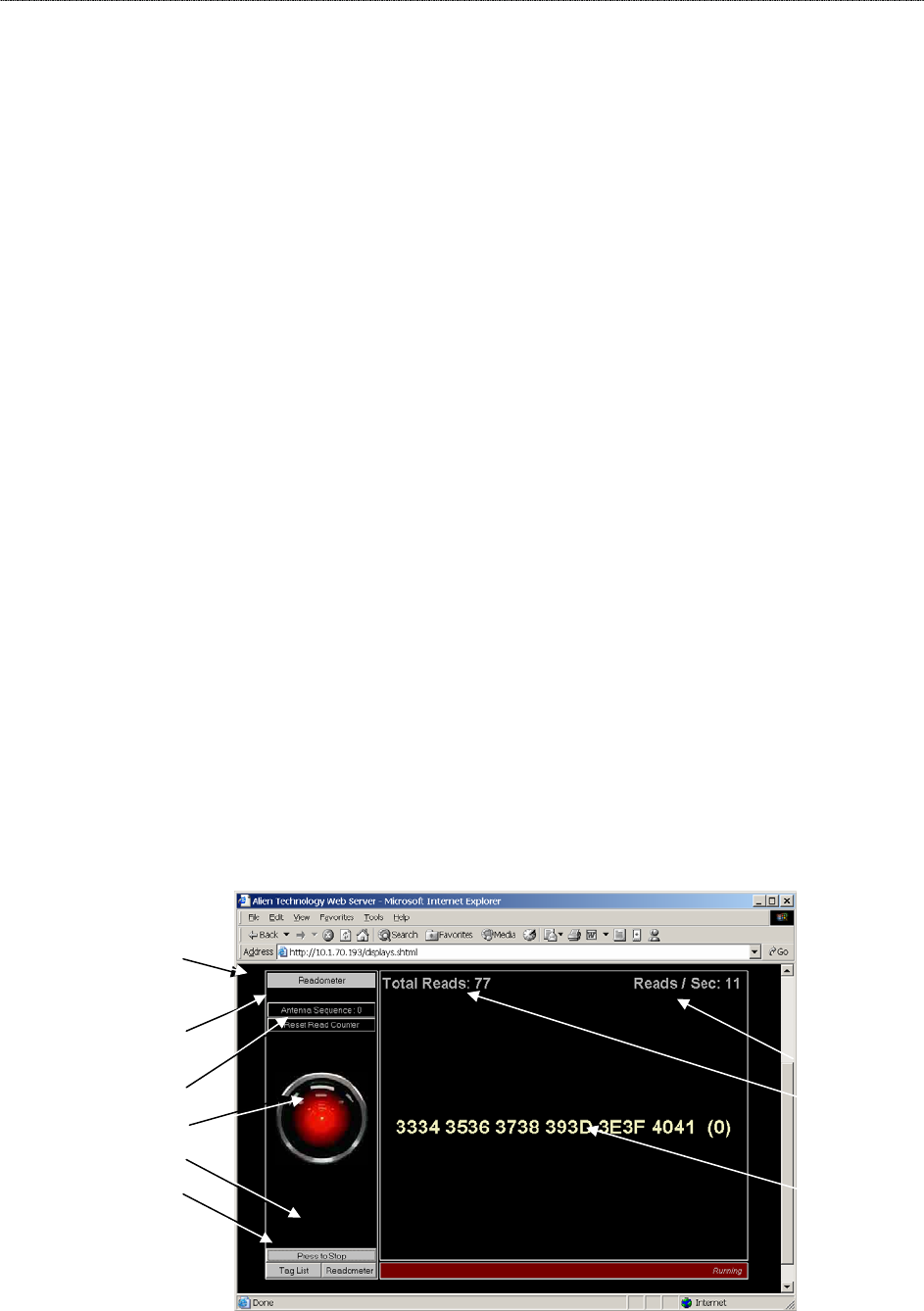
Readometer
The “readometer” graphically displays a single tag and antenna information in
real time.
This screen allows the user to:
• View a single tag (as returned by the Get TagList / Set AcquireMode= Global
Scroll command) and the reading antenna
• View a cumulative and dynamic number of reads since starting or resetting
this value
• View a dynamic Reads per Second value for the current tag
• Change the antenna sequence (see “General Commands”)
• Reset the Total Reads counter
• Stop/start the tag reading operation
• Switch to a different display mode
Reads / second
Total cumulative
reads (since
reset)
Current tag ID
and reading
antenna (in
parentheses)
Readometer
mode is active
Antenna
Sequence
selector/display
Click to reset
total reads
Click either to
stop/start tag
reads
Click to select an
alternative read
mode
CHAPTER 7 WEB BASED APPLICATION EXAMPLES
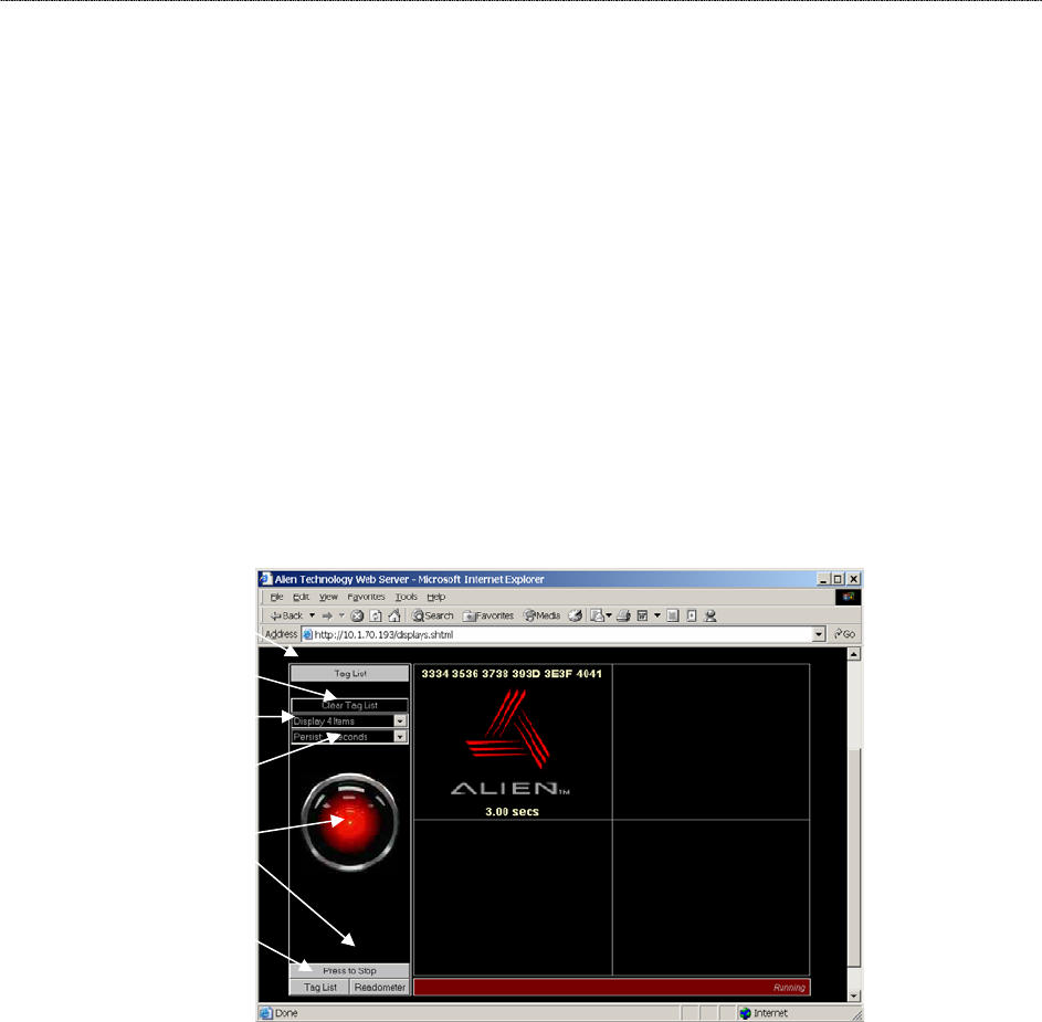
Tag List
The Tag List applet provides a graphical view of the reader’s current tag list.
This screen allows the user to:
• View tags that have been read and acquired by the reader most recently
(typically using get tagList / set acquireMode = Inventory)
• View the Persist Time countdown for each tag after it is read
• Clear the tag list manually
• Change the number of cells in the display grid via pulldown menu
• Change the Persist Time via pulldown menu
• Start/stop tag reading
• Switch to a different tag display mode.
Displays data for
all tags currently
and recently read,
including...
• Tag ID...
• Product icon
(optional)...
and
• Persist Time
countdown.
Current display
mode
Clear Tag List
Display (n)
Items
Persist (n)
Seconds
Start/Stop
reading
Switch display
mode

CHAPTER 7 WEB BASED APPLICATION EXAMPLES
Optimize Reader Settings
On each of the Tag List and Readometer screens is a small checkbox option
entitled ‘Optimize Reader Settings’, which by default is checked (a tick mark is
present).
When checked this tells the applet to optimize the reader settings the next time
one of the two applications is started (i.e., the HAL eye turns to red). The
following optimization settings are made to the reader depending on the
application that is started:
Readometer Settings
When the Readometer is started with the optimize option checked, the following
commands are issued to the reader to put it into an optimized state for
readometer readings.
• Set persisttime = 0
• Set TagListFormat = Text
• AutoModeReset
• Set AcquireMode = Global Scroll
When running, the readometer performs repeated bursts of ‘get taglist 25’
followed by a 200 ms pause. The timing results displayed on the screen are
calculated based on each ‘get taglist 25’ command. Thus for optimal timings,
Global Scroll is used for the Acquire Mode.
The auto mode is reset, and left off; the readometer screen always works in
foreground mode.
When the optimize option is turned off, only one command is issued to the reader
when readometer is started:
• Set TagListFormat = Text
Tag List Settings
When the Tag List is started with the optimize option checked, the following
commands are issued to the reader to put it into an optimized state for tag list
readings.
• Set persisttime = -1
• Set TagListFormat = Text
• AutoModeReset
• Set AcquireMode = Inventory
When running, the tag list switches on auto mode, forcing the reader into
autonomous acquisitions as fast as it can. The optimized acquisition mode is
Inventory and the persist time is –1, telling the reader to build up a tag list until
next interrogated. While the reader is building its tag list, the applet periodically

CHAPTER 7 WEB BASED APPLICATION EXAMPLES
(~every 250ms) issues a ‘get taglist’ command, forcing the full tag list to be
returned and the reader to reset its internal tag list.
When the optimize option is turned off, only one command is issued to the reader
when tag list is started:
• Set TagListFormat = Text
Advanced Tag List Options
By turning off the optimization check box and running tag list, the reader can be
set up manually to perform different actions:
RUNNING TAG LIST USING GLOBAL SCROLL AS THE ACQUIRE MODE
In some instances it is desirable to set the acquire mode to Global Scroll. By
default, with the tag list optimize checkbox on, the tag list will set the reader into
Inventory mode. However with the optimize checkbox off, the following manual
settings can be made:
• Set AcquireMode = Global Scroll
The next time the tag list is started, it will run using the new settings.
RUNNING TAG LIST IN DUTY CYCLE MODE
In some instances it is desirable to run the reader in duty cycle mode, where
instead of reading tags without a break, a timed pause is inserted into the read-
cycle. By default, with the optimize checkbox on, the Tag List will set the reader
into full time acquire mode. However with the optimize checkbox off, the following
manual settings can be made:
• Set AutoStopTimer = 500
• Set AutoTruePause = 200
• Set AutoFalsePause = 200
The next time the Tag List is started, it will run using the new settings, forcing it
into a cylce of reading tags for 500ms, followed by a 200ms pause regardless of
whether tags were found or not. For further details on these commands and other
autonomous mode options, please refer to the autonomous mode overview in
this document.