Allied Telesis K K AP500 Cloud-Managed Enterprise-class Wireless Access Point with IEEE802.11a/b/g/n/ac Dual Radio User Manual 0208
Allied Telesis K.K. Cloud-Managed Enterprise-class Wireless Access Point with IEEE802.11a/b/g/n/ac Dual Radio Users Manual 0208
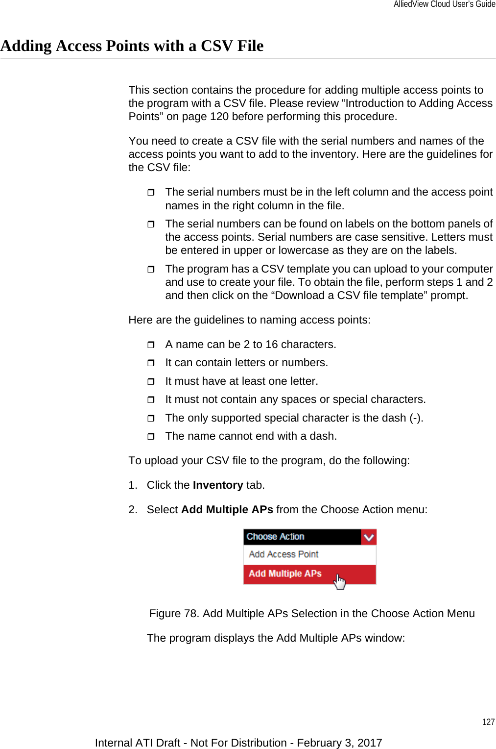
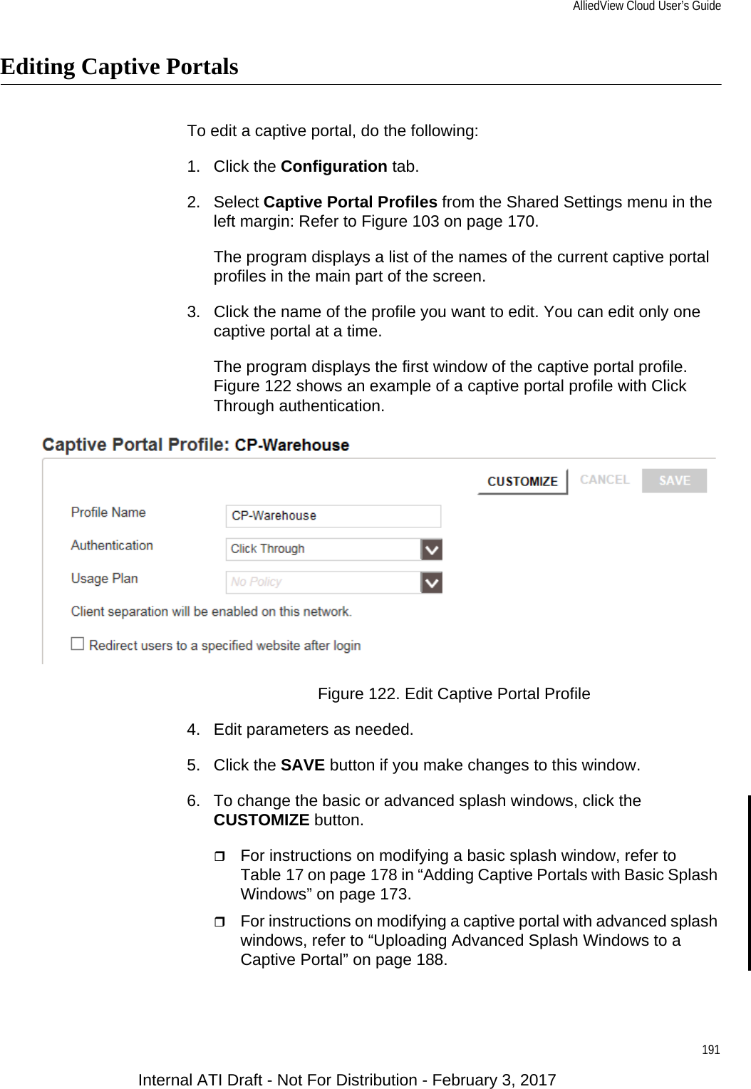
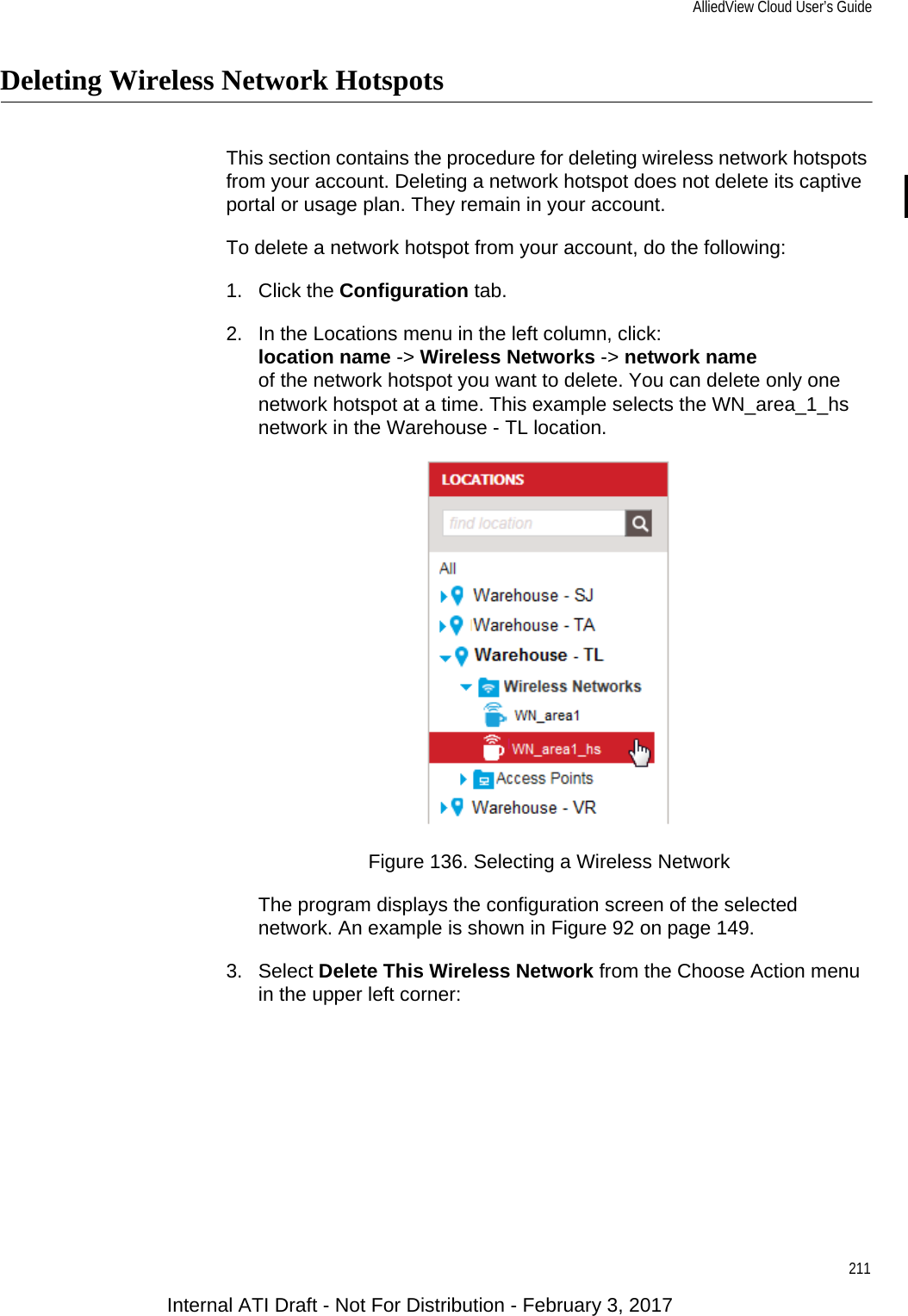
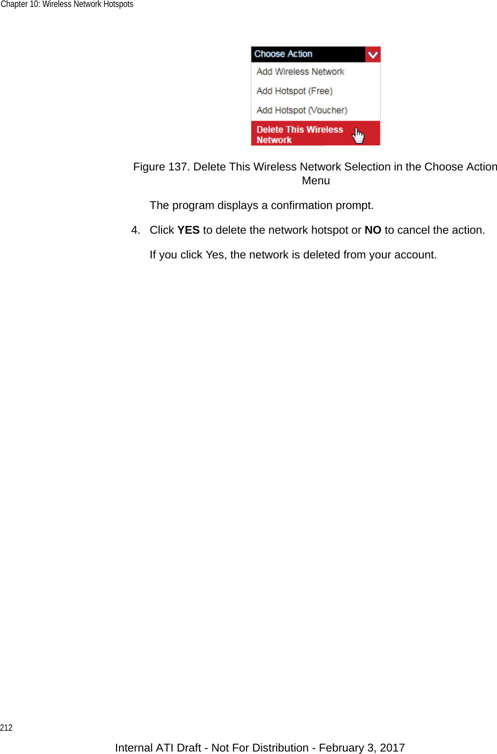
Contents
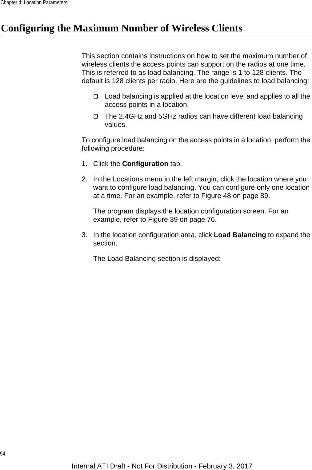
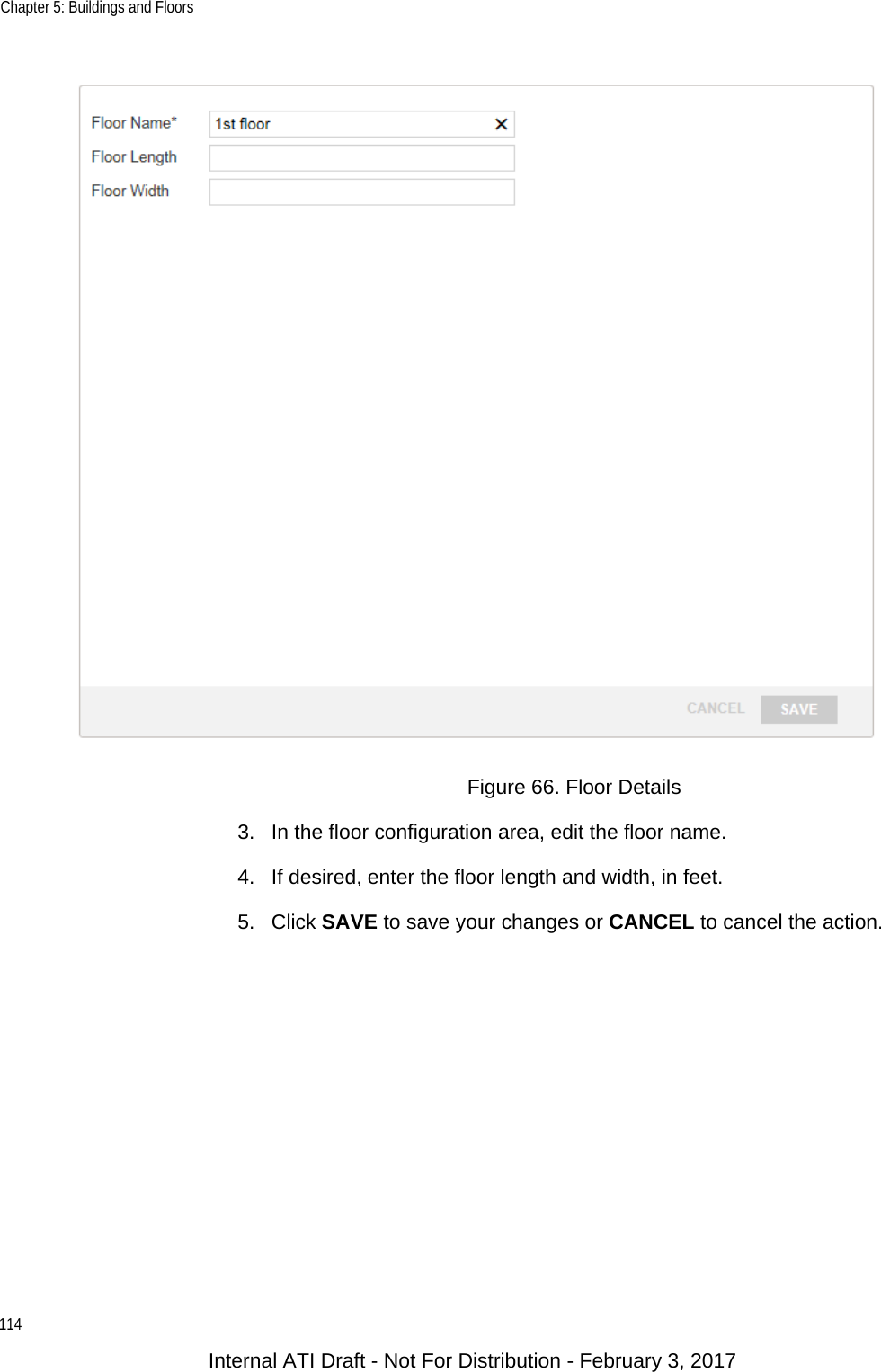
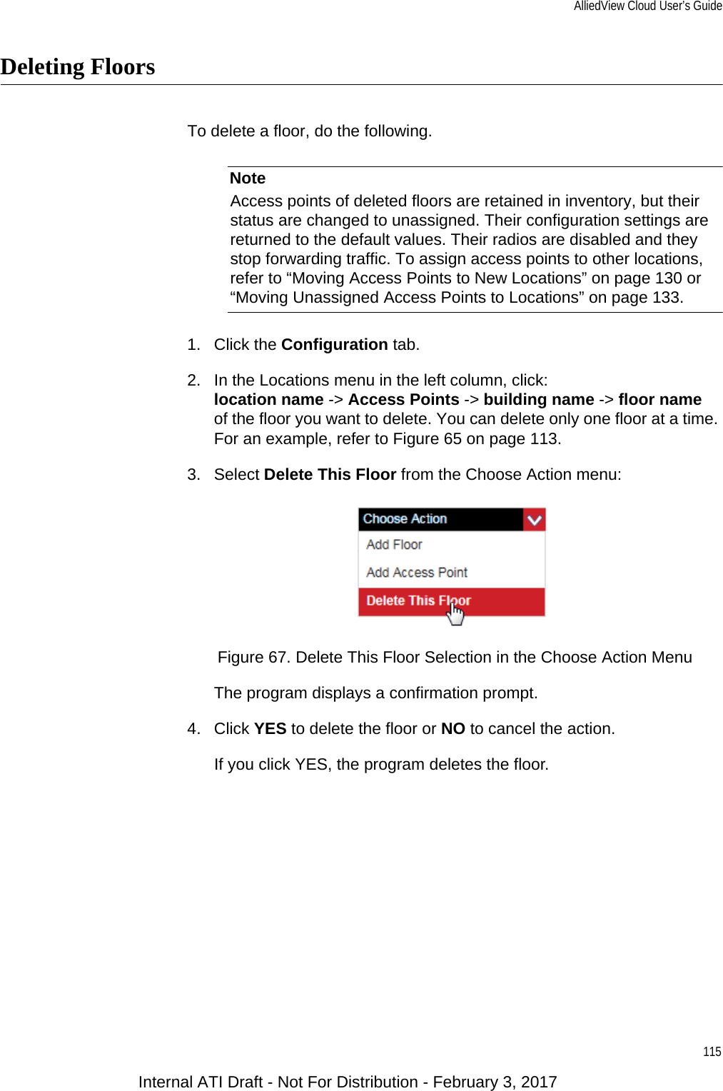
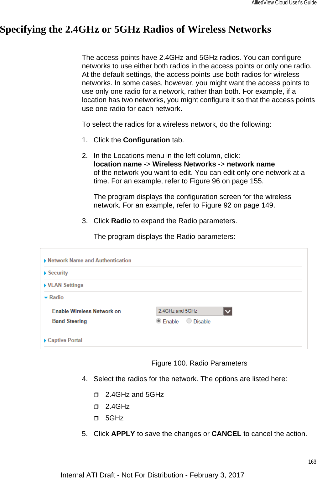
- 1. Users Manual
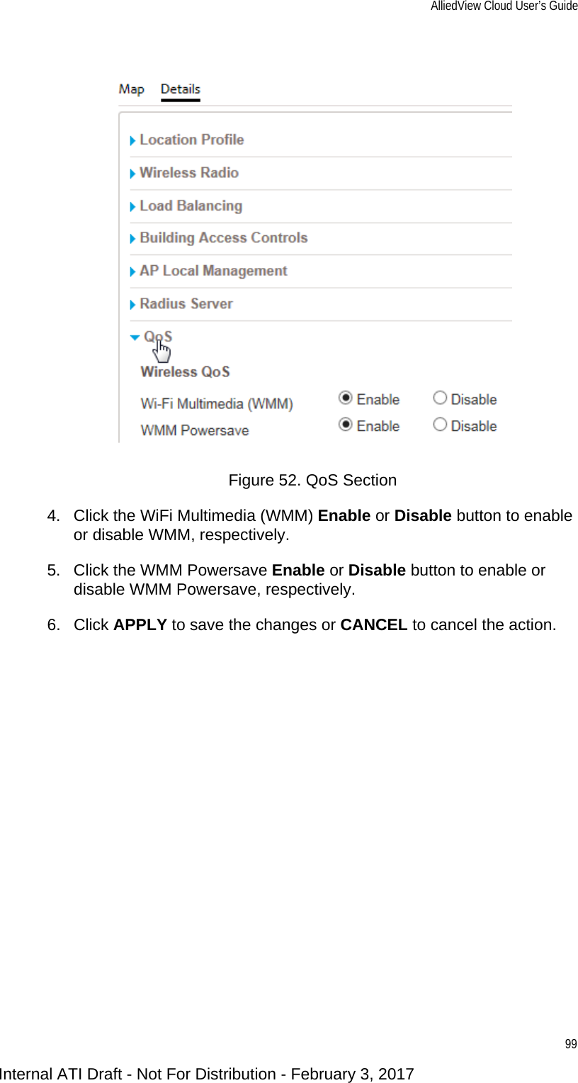
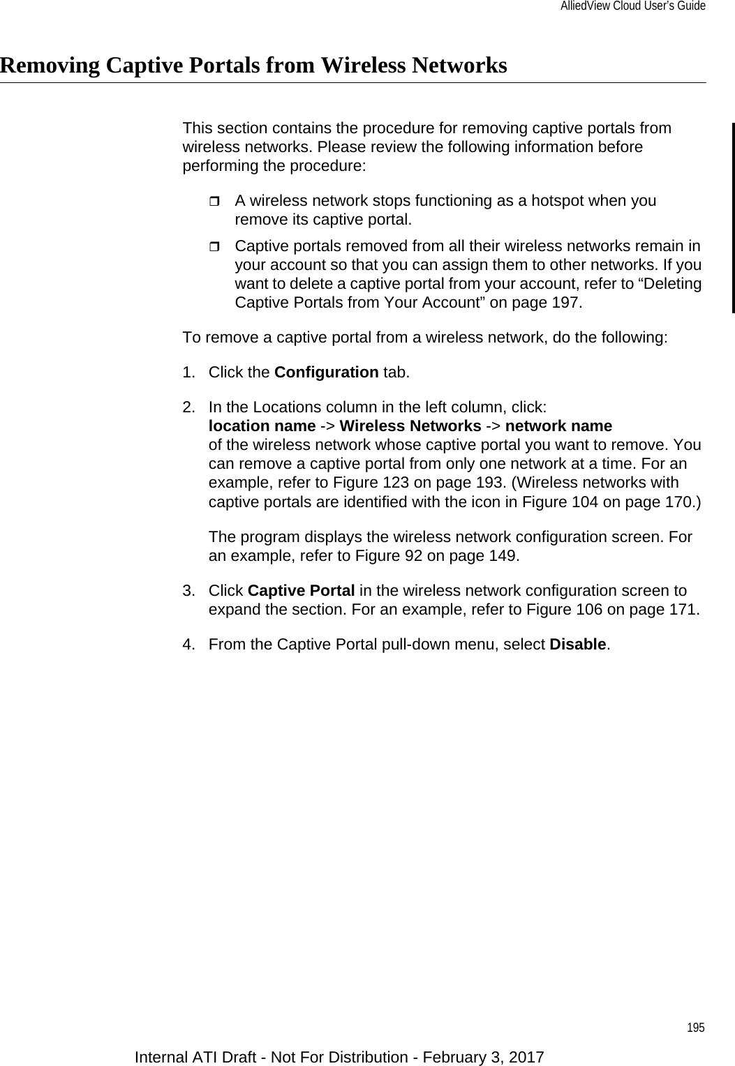
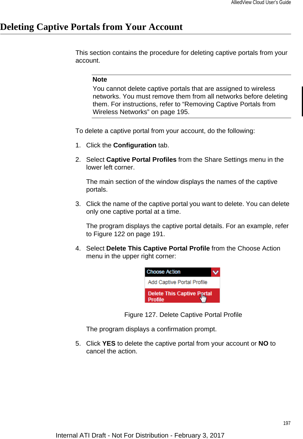
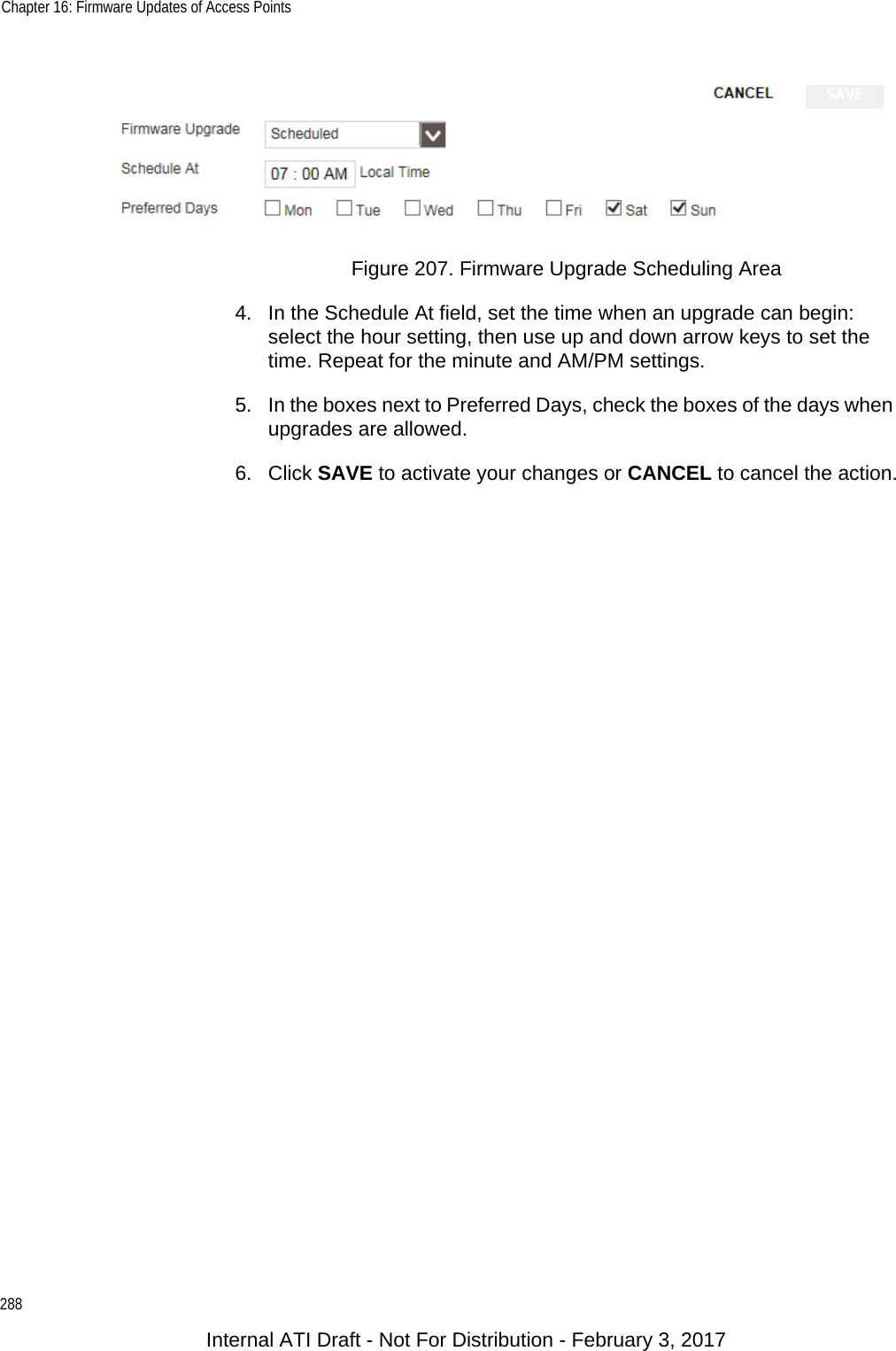
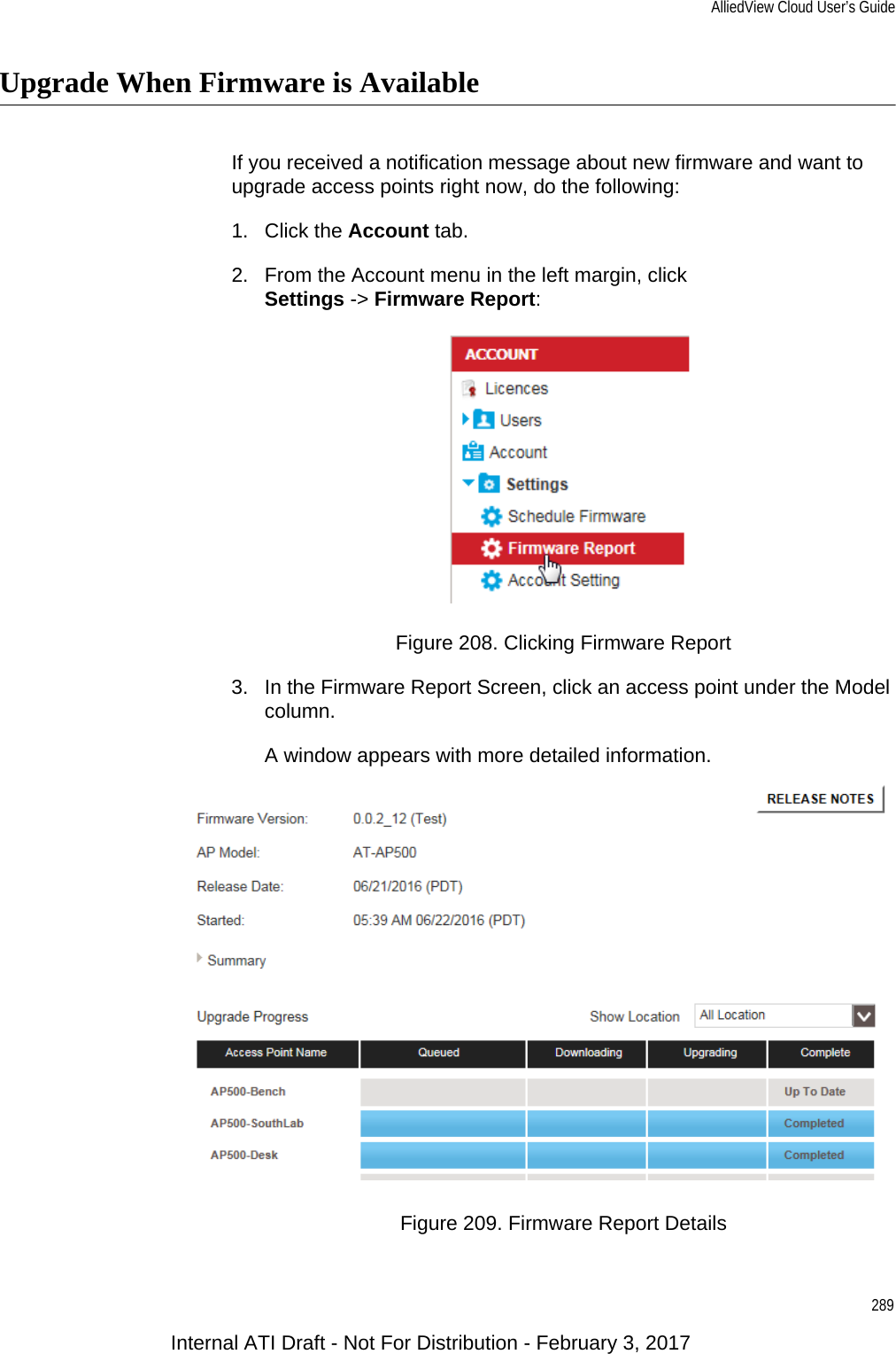
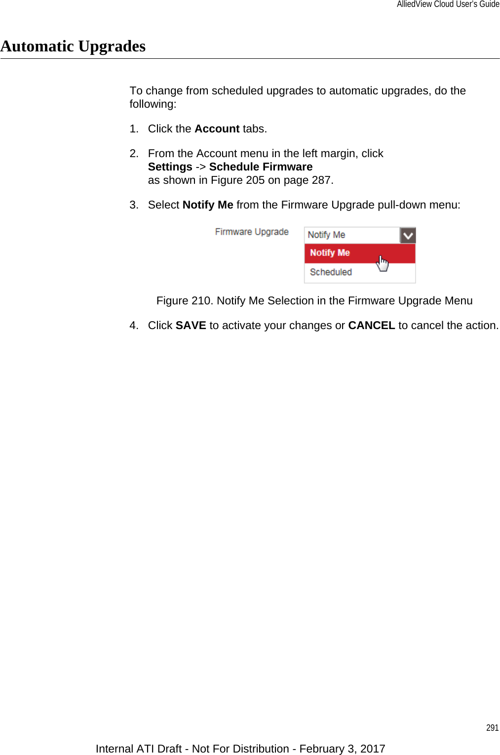
- 2. Users Manual_revised0119
- 3. Users Manual_0208
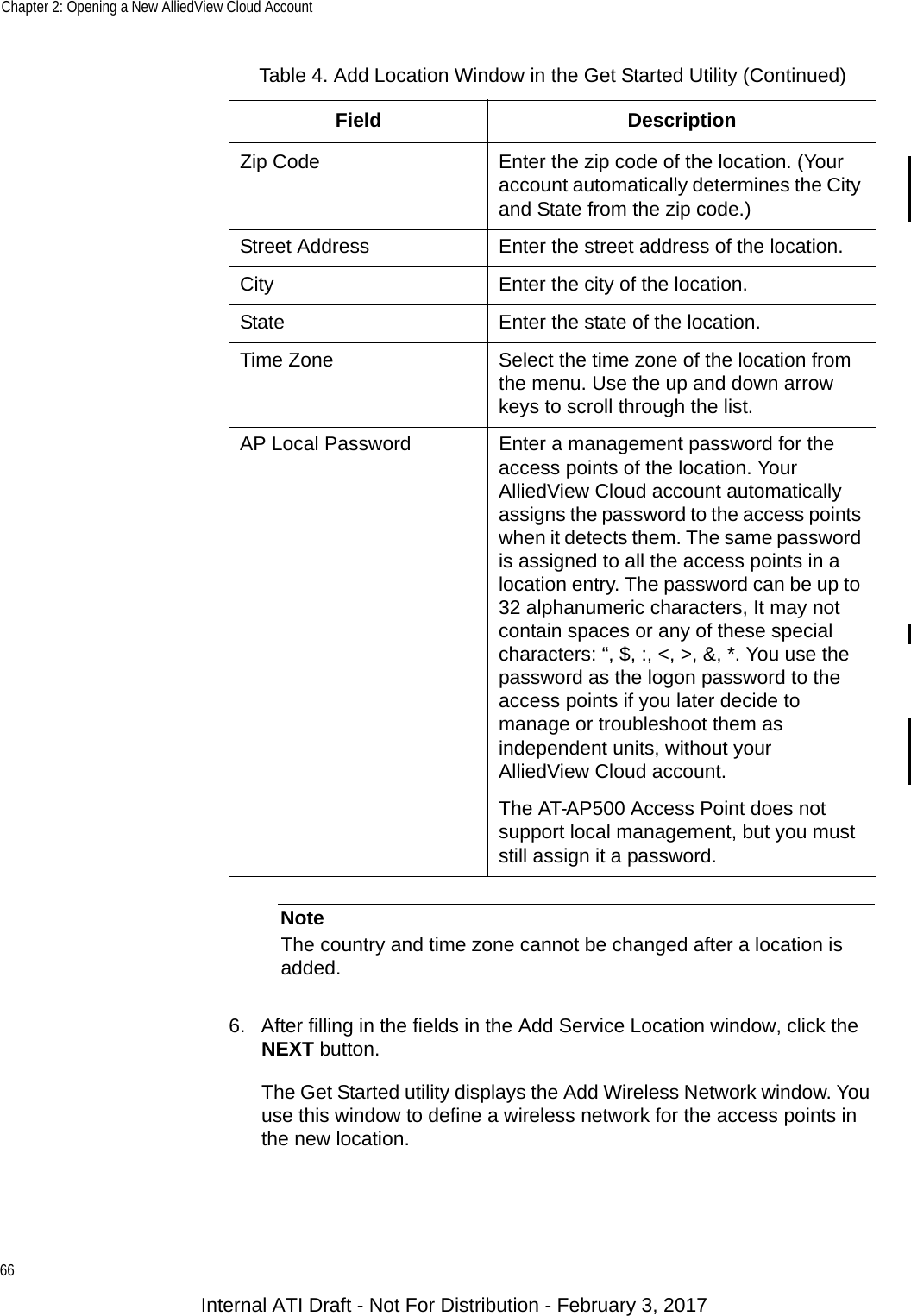
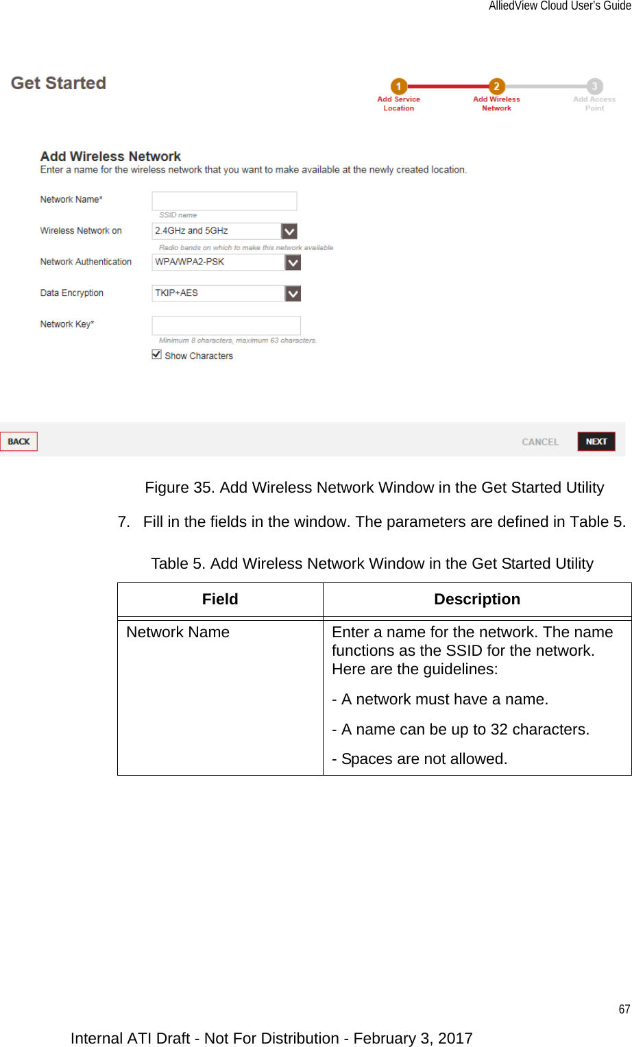
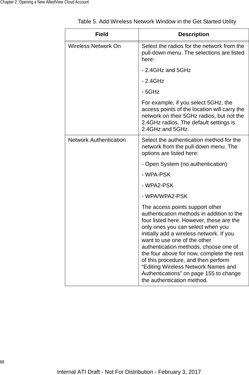
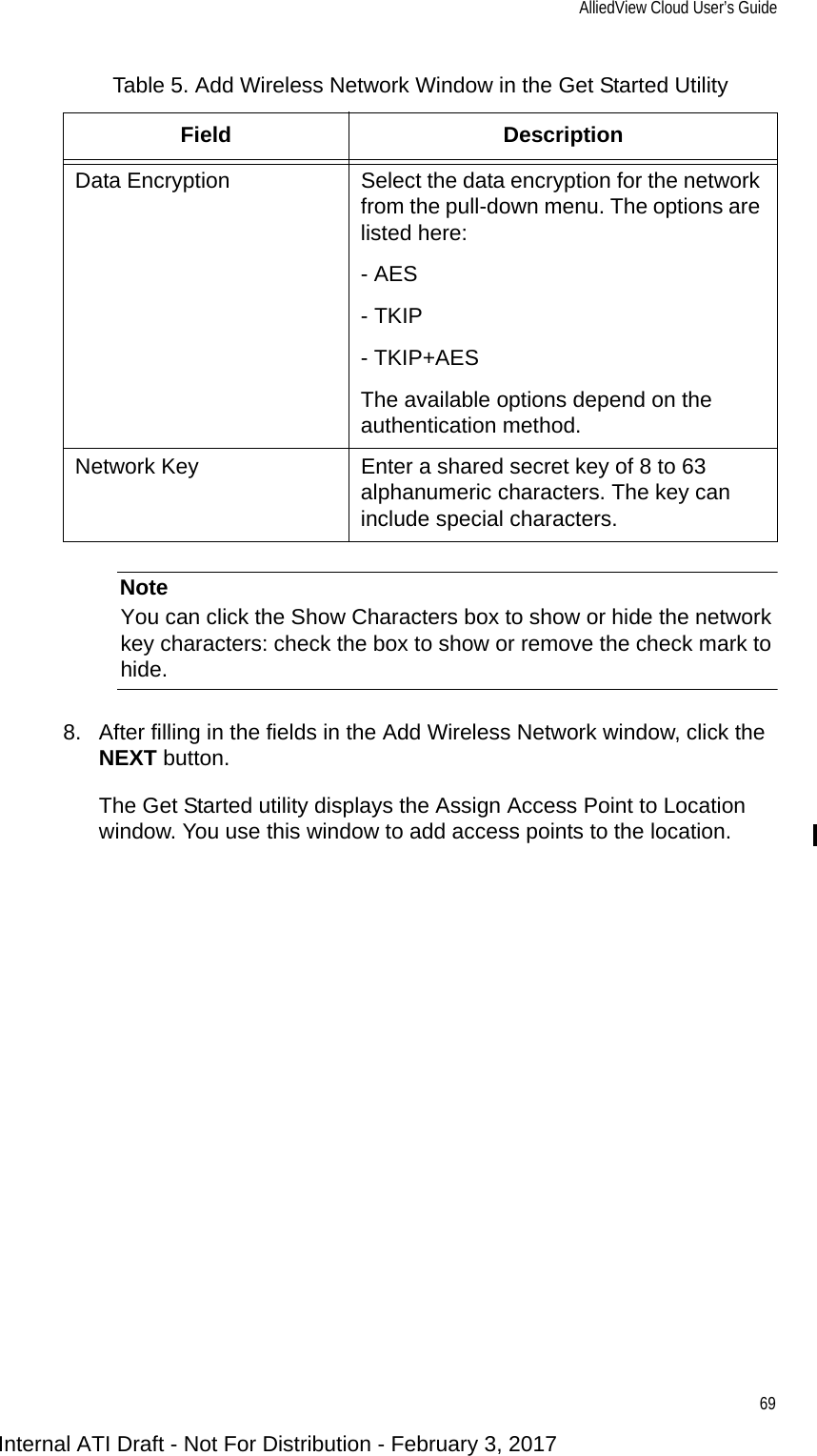
Users Manual_0208