Alvarion Technologies BMAX-BA23 Base station BreezeMax 2300 User Manual Manual Filter page
Alvarion Technologies Ltd. Base station BreezeMax 2300 Manual Filter page
Contents
- 1. User Manual
- 2. Manual Filter page
Manual Filter page
Installation Instructions for Operating in the FCC WCS C and D bands TDD
- 1 -
P/N 215656 May 2010
This document describes how to install and use the FL1500, required for compliance with FCC regulations for the
2.3 GHz WCS bands C and D.
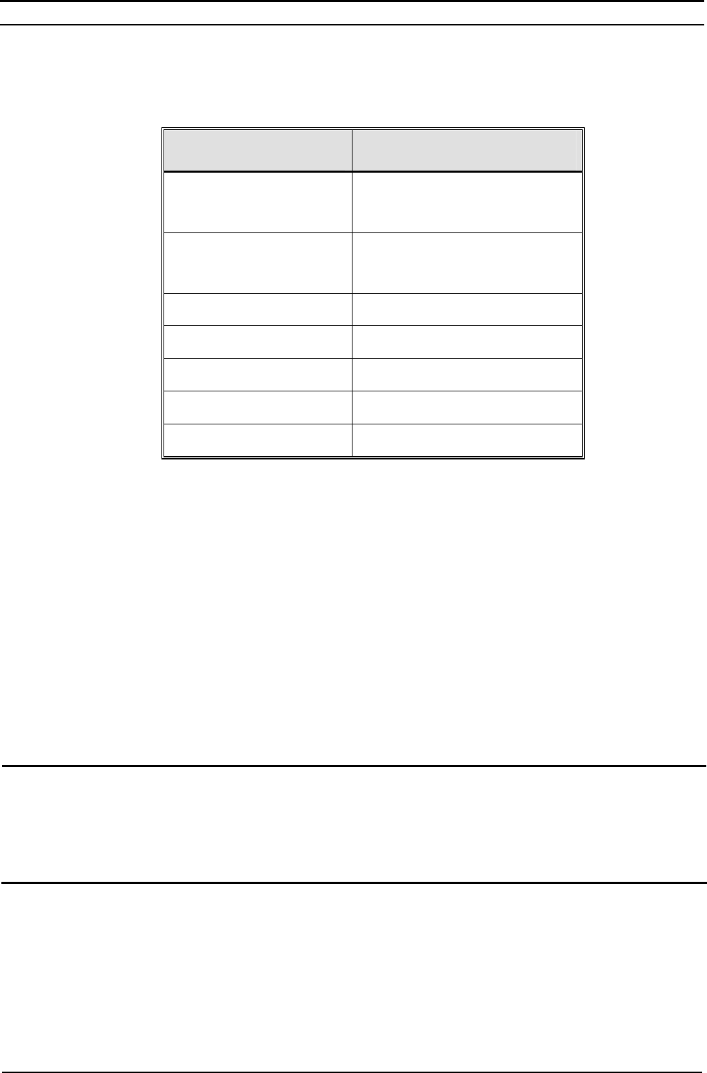
FL1500 Specification
Item Specifications
Frequency Range 2315MHz ~ 2318.5MHz
2346.5MHz ~ 2350MHz
Central Frequency Fc1 = 2316.75MHz
Fc2 = 2348.25MHz
Insertion Loss 2.7dB Max
Connectors N-Type, Female
Dimensions 148 x 106 x 85 mm
Operating Temperature -40°C to +70°C
Operating Humidity RH 20% ~ 98%, Waterproof IP67
Package Content
• FL1500 Filter
Additional Items Required for Installation (available for ordering)
• Mounting Kit MD5088 (two metal bands)
• Two RF cables from the list below for connecting the Filter to the ODU and antenna:
o 0.5m - P/N 835308
o 1m – P/N 835307
o 1.5m – P/N 723218
Installation Guidelines
WARNING: ONLY experienced installation professionals who are familiar with local building and safety codes and,
wherever applicable, are licensed by the appropriate government regulatory authorities should install outdoor
units and antennas. Failure to do so may void the product warranty and may expose the end user or Service
Provider to legal and financial liabilities. The manufacturer and its resellers or distributors are not liable for
injury, damage or regulation violations associated with the installation of outdoor units or antennas.
• Filters must be installed at the Base Station site and at all CPE sites, between the antenna RF port of the 2.3
GHz ODU and the antenna.
• The Filter should be installed between the ODU and the antenna, taking into account the lengths of the
connecting cables.
Installation Instructions for Operating in the FCC WCS C and D bands TDD
- 2 -
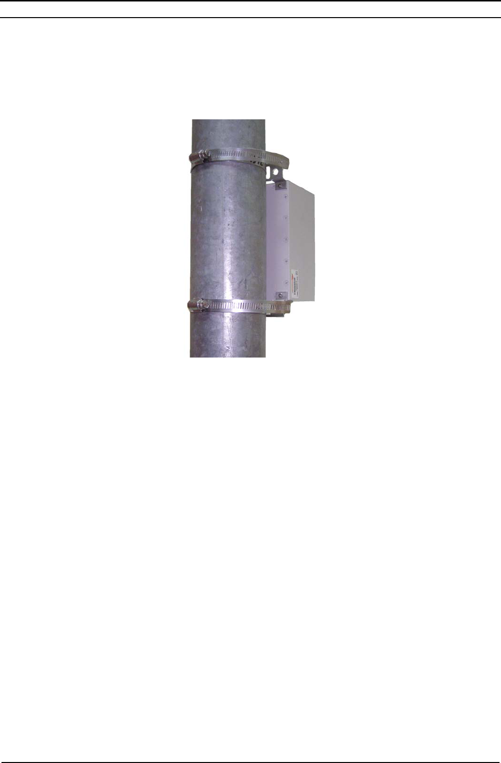
Installing the Filter
1. Attach the Filter to the pole using the two metal bands, as shown below. The Filter must be installed with the
RF connectors facing downward.
2. Connect the ANT RF port of the ODU to the INPUT connector of the Filter.
3. Connect the OUTPUT connector of the Filter to the antenna.
Operation
When configuring the Frequency and Bandwidth parameters, the following rules must be followed:
1. The frequency must be either 2316.75 or 2348.25 MHz.
2. The Bandwidth must be 3.5 MHz
P/N 215656 May 2010