Alvarion Technologies BMAX-OR-25 BreezeMax 4Motion Broadband Wireless System User Manual 4Motion System Manual
Alvarion Technologies Ltd. BreezeMax 4Motion Broadband Wireless System 4Motion System Manual
Contents
- 1. Manual 1
- 2. Manual 2
- 3. Manual 3
- 4. Manual 4
- 5. Manual
Manual 1

4Motion®
System Manual
Release 2.5
March 2009

Document History
4Motion ii System Manual
Document History
Topic Description Date Issued
Preliminary Release for Early Field
Trials
New System Manual January 2008
Preliminary Release for Beta May 2008
Release for GA July 2008
SDR
Section 1.3.3
Removed August 2008
Template Changed September 2008
Power Feeder
Section 1.3.8
Supported in release 2.5 December 2008
7 MHz Channel Bandwidth
Table 1-4, relevant sections in
Chapter 4.
Supported in release 2.5 December 2008
Installing 4x2 ODU
Section 2.1.4
Updated (including new installation options) December 2008
Installation recommendation
Section 2.3.9.1
Recommendation on installing AUs in a
3-sector configuration
December 2008
Trap Manager
Section 3.1.6
Modified instructions for initial configuration December 2008
Operation and Administration Using
the CLI
Chapter 4
Updated to reflect NPU SW Version 2_5_1_8 December 2008

Legal Rights
4Motion iii System Manual
Legal Rights
© Copyright 2008 Alvarion Ltd. All rights reserved.
The material contained herein is proprietary, privileged, and confidential and
owned by Alvarion or its third party licensors. No disclosure thereof shall be made
to third parties without the express written permission of Alvarion Ltd.
Alvarion Ltd. reserves the right to alter the equipment specifications and
descriptions in this publication without prior notice. No part of this publication
shall be deemed to be part of any contract or warranty unless specifically
incorporated by reference into such contract or warranty.
Trade Names
Alvarion®, BreezeCOM®, WALKair®, WALKnet®, BreezeNET®, BreezeACCESS®,
BreezeLINK®, BreezeMAX®, BreezeLITE®, BreezePHONE®, 4Motion®,
BreezeCONFIG™, AlvariSTAR™, AlvariCRAFT™, MGW™, eMGW™ and/or other
products and/or services referenced here in are either registered trademarks,
trademarks or service marks of Alvarion Ltd.
All other names are or may be the trademarks of their respective owners.
“WiMAX Forum” is a registered trademark of the WiMAX Forum. “WiMAX,” the
WiMAX Forum logo, “WiMAX Forum Certified,” and the WiMAX Forum Certified
logo are trademarks of the WiMAX Forum.
Statement of Conditions
The information contained in this manual is subject to change without notice.
Alvarion Ltd. shall not be liable for errors contained herein or for incidental or
consequential damages in connection with the furnishing, performance, or use of
this manual or equipment supplied with it.
Warranties and Disclaimers
All Alvarion Ltd. ("Alvarion") products purchased from Alvarion or through any of
Alvarion's authorized resellers are subject to the following warranty and product
liability terms and conditions.
Exclusive Warranty
(a) Alvarion warrants that the Product hardware it supplies and the tangible
media on which any software is installed, under normal use and conditions, will
be free from significant defects in materials and workmanship for a period of
fourteen (14) months from the date of shipment of a given Product to Purchaser
(the "Warranty Period"). Alvarion will, at its sole option and as Purchaser's sole

Legal Rights
4Motion iv System Manual
remedy, repair or replace any defective Product in accordance with Alvarion'
standard R&R procedure.
(b) With respect to the Firmware, Alvarion warrants the correct functionality
according to the attached documentation, for a period of fourteen (14) month from
invoice date (the "Warranty Period")". During the Warranty Period, Alvarion may
release to its Customers firmware updates, which include additional performance
improvements and/or bug fixes, upon availability (the "Warranty"). Bug fixes,
temporary patches and/or workarounds may be supplied as Firmware updates.
Additional hardware, if required, to install or use Firmware updates must be
purchased by the Customer. Alvarion will be obligated to support solely the two (2)
most recent Software major releases.
ALVARION SHALL NOT BE LIABLE UNDER THIS WARRANTY IF ITS TESTING
AND EXAMINATION DISCLOSE THAT THE ALLEGED DEFECT IN THE PRODUCT
DOES NOT EXIST OR WAS CAUSED BY PURCHASER'S OR ANY THIRD
PERSON'S MISUSE, NEGLIGENCE, IMPROPER INSTALLATION OR IMPROPER
TESTING, UNAUTHORIZED ATTEMPTS TO REPAIR, OR ANY OTHER CAUSE
BEYOND THE RANGE OF THE INTENDED USE, OR BY ACCIDENT, FIRE,
LIGHTNING OR OTHER HAZARD.
Disclaimer
(a) The Software is sold on an "AS IS" basis. Alvarion, its affiliates or its licensors
MAKE NO WARRANTIES, WHATSOEVER, WHETHER EXPRESS OR IMPLIED,
WITH RESPECT TO THE SOFTWARE AND THE ACCOMPANYING
DOCUMENTATION. ALVARION SPECIFICALLY DISCLAIMS ALL IMPLIED
WARRANTIES OF MERCHANTABILITY AND FITNESS FOR A PARTICULAR
PURPOSE AND NON-INFRINGEMENT WITH RESPECT TO THE SOFTWARE.
UNITS OF PRODUCT (INCLUDING ALL THE SOFTWARE) DELIVERED TO
PURCHASER HEREUNDER ARE NOT FAULT-TOLERANT AND ARE NOT
DESIGNED, MANUFACTURED OR INTENDED FOR USE OR RESALE IN
APPLICATIONS WHERE THE FAILURE, MALFUNCTION OR INACCURACY OF
PRODUCTS CARRIES A RISK OF DEATH OR BODILY INJURY OR SEVERE
PHYSICAL OR ENVIRONMENTAL DAMAGE ("HIGH RISK ACTIVITIES"). HIGH
RISK ACTIVITIES MAY INCLUDE, BUT ARE NOT LIMITED TO, USE AS PART OF
ON-LINE CONTROL SYSTEMS IN HAZARDOUS ENVIRONMENTS REQUIRING
FAIL-SAFE PERFORMANCE, SUCH AS IN THE OPERATION OF NUCLEAR
FACILITIES, AIRCRAFT NAVIGATION OR COMMUNICATION SYSTEMS, AIR
TRAFFIC CONTROL, LIFE SUPPORT MACHINES, WEAPONS SYSTEMS OR
OTHER APPLICATIONS REPRESENTING A SIMILAR DEGREE OF POTENTIAL
HAZARD. ALVARION SPECIFICALLY DISCLAIMS ANY EXPRESS OR IMPLIED
WARRANTY OF FITNESS FOR HIGH RISK ACTIVITIES.

Legal Rights
4Motion v System Manual
(b) PURCHASER'S SOLE REMEDY FOR BREACH OF THE EXPRESS
WARRANTIES ABOVE SHALL BE REPLACEMENT OR REFUND OF THE
PURCHASE PRICE AS SPECIFIED ABOVE, AT ALVARION'S OPTION. TO THE
FULLEST EXTENT ALLOWED BY LAW, THE WARRANTIES AND REMEDIES SET
FORTH IN THIS AGREEMENT ARE EXCLUSIVE AND IN LIEU OF ALL OTHER
WARRANTIES OR CONDITIONS, EXPRESS OR IMPLIED, EITHER IN FACT OR BY
OPERATION OF LAW, STATUTORY OR OTHERWISE, INCLUDING BUT NOT
LIMITED TO WARRANTIES, TERMS OR CONDITIONS OF MERCHANTABILITY,
FITNESS FOR A PARTICULAR PURPOSE, SATISFACTORY QUALITY,
CORRESPONDENCE WITH DESCRIPTION, NON-INFRINGEMENT, AND
ACCURACY OF INFORMATION GENERATED. ALL OF WHICH ARE EXPRESSLY
DISCLAIMED. ALVARION' WARRANTIES HEREIN RUN ONLY TO PURCHASER,
AND ARE NOT EXTENDED TO ANY THIRD PARTIES. ALVARION NEITHER
ASSUMES NOR AUTHORIZES ANY OTHER PERSON TO ASSUME FOR IT ANY
OTHER LIABILITY IN CONNECTION WITH THE SALE, INSTALLATION,
MAINTENANCE OR USE OF ITS PRODUCTS.
Limitation of Liability
(a) ALVARION SHALL NOT BE LIABLE TO THE PURCHASER OR TO ANY THIRD
PARTY, FOR ANY LOSS OF PROFITS, LOSS OF USE, INTERRUPTION OF
BUSINESS OR FOR ANY INDIRECT, SPECIAL, INCIDENTAL, PUNITIVE OR
CONSEQUENTIAL DAMAGES OF ANY KIND, WHETHER ARISING UNDER
BREACH OF CONTRACT, TORT (INCLUDING NEGLIGENCE), STRICT LIABILITY
OR OTHERWISE AND WHETHER BASED ON THIS AGREEMENT OR
OTHERWISE, EVEN IF ADVISED OF THE POSSIBILITY OF SUCH DAMAGES.
(b) TO THE EXTENT PERMITTED BY APPLICABLE LAW, IN NO EVENT SHALL
THE LIABILITY FOR DAMAGES HEREUNDER OF ALVARION OR ITS EMPLOYEES
OR AGENTS EXCEED THE PURCHASE PRICE PAID FOR THE PRODUCT BY
PURCHASER, NOR SHALL THE AGGREGATE LIABILITY FOR DAMAGES TO ALL
PARTIES REGARDING ANY PRODUCT EXCEED THE PURCHASE PRICE PAID
FOR THAT PRODUCT BY THAT PARTY (EXCEPT IN THE CASE OF A BREACH OF
A PARTY'S CONFIDENTIALITY OBLIGATIONS).
Radio Frequency Interference Statement
The Base Transceiver Station (BTS) equipment has been tested and found to
comply with the limits for a class A digital device, pursuant to ETSI EN 301 489-1
rules and Part 15 of the FCC Rules. These limits are designed to provide
reasonable protection against harmful interference when the equipment is
operated in commercial, business and industrial environments. This equipment
generates, uses, and can radiate radio frequency energy and, if not installed and
used in accordance with the instruction manual, may cause harmful interference
to radio communications. Operation of this equipment in a residential area is

Legal Rights
4Motion vi System Manual
likely to cause harmful interference in which case the user will be required to
correct the interference at the user's own expense.
FCC Radiation Hazard Warning
To comply with FCC RF exposure requirements in Section 1.1307 and 2.1091 of
FCC Rules, the antenna used for this transmitter must be fixed-mounted on
outdoor permanent structures with a separation distance of at least 2 meter from
all persons.
R&TTE Compliance Statement
This equipment complies with the appropriate essential requirements of Article 3
of the R&TTE Directive 1999/5/EC.
Safety Considerations - General
For the following safety considerations, "Instrument" means the BreezeMAX units'
components and their cables.
Grounding
BTS chassis, Power Feeders and Outdoor Units are required to be bonded to
protective grounding using the bonding stud or screw provided with each unit.
Safety Considerations - DC Powered Equipment (BTS & Power Feeder)
Restricted Access Area: The DC powered equipment should only be installed in a
Restricted Access Area.
Installation Codes: The equipment must be installed according to the latest
edition of the country national electrical codes. For North America, equipment
must be installed in accordance with the US National Electrical Code and the
Canadian Electrical Code.
Overcurrent Protection: A readily accessible Listed branch circuit overcurrent
protective device, rated 60A for the BTS or 20A for the Power Feeder, must be
incorporated in the building wiring.
CAUTION: This equipment is designed to permit connection between the earthed
conductor of the DC supply circuit and the grounding conductor at the
equipment. See installation instructions.
CAUTION ATTENTION
Risk of electric shock and energy
hazard.Disconnecting one Power Interface Unit
(PIU) disconnects only one PIU module. To
isolate the BTS completely, disconnect both
PIUs
Risque de décharge électrique et
d'electrocution. La déconnection d'un seul
module d'alimentation (PIU) n'isole pas
complètement la Station de Base. Pour cela, il
faut impérativement débrancher les deux
modules d'alimentation (PIU).

Legal Rights
4Motion vii System Manual
The equipment must be connected directly to the DC Supply System
grounding electrode conductor.
All equipment in the immediate vicinity must be grounded in the same way,
and not be grounded elsewhere.
The DC supply system is to be local, i.e. within the same premises as the
equipment.
There shall be no disconnect device between the grounded circuit conductor of
the DC source (return) and the point of connection of the grounding electrode
conductor.
Lithium Battery
The battery on the NPU card is not intended for replacement.
Caution
To avoid electrical shock, do not perform any servicing unless you are qualified to
do so.
Line Voltage
Before connecting this instrument to the power line, make sure that the voltage of
the power source matches the requirements of the instrument.
Radio
The instrument transmits radio energy during normal operation. To avoid possible
harmful exposure to this energy, do not stand or work for extended periods of time
in front of its antenna. The long-term characteristics or the possible physiological
effects of radio frequency electromagnetic fields have not been yet fully
investigated.
Outdoor Units and Antennas Installation and Grounding
Ensure that outdoor units, antennas and supporting structures are properly
installed to eliminate any physical hazard to either people or property. Make sure
that the installation of the outdoor unit, antenna and cables is performed in
accordance with all relevant national and local building and safety codes. Even
where grounding is not mandatory according to applicable regulation and national
codes, it is highly recommended to ensure that the outdoor unit and the antenna
mast (when using external antenna) are grounded and suitable lightning
protection devices are used so as to provide protection against voltage surges and
static charges. In any event, Alvarion is not liable for any injury, damage or

Legal Rights
4Motion viii System Manual
regulation violations associated with or caused by installation, grounding or
lightning protection.
Disposal of Electronic and Electrical Waste
Disposal of Electronic and Electrical Waste
Pursuant to the WEEE EU Directive electronic and electrical waste must not be disposed of with
unsorted waste. Please contact your local recycling authority for disposal of this product.

Important Notice
4Motion ix System Manual
Important Notice
This user manual is delivered subject to the following conditions and restrictions:
This manual contains proprietary information belonging to Alvarion Ltd. Such
information is supplied solely for the purpose of assisting properly authorized
users of the respective Alvarion products.
No part of its contents may be used for any other purpose, disclosed to any
person or firm or reproduced by any means, electronic and mechanical,
without the express prior written permission of Alvarion Ltd.
The text and graphics are for the purpose of illustration and reference only.
The specifications on which they are based are subject to change without
notice.
The software described in this document is furnished under a license. The
software may be used or copied only in accordance with the terms of that
license.
Information in this document is subject to change without notice. Corporate
and individual names and data used in examples herein are fictitious unless
otherwise noted.
Alvarion Ltd. reserves the right to alter the equipment specifications and
descriptions in this publication without prior notice. No part of this
publication shall be deemed to be part of any contract or warranty unless
specifically incorporated by reference into such contract or warranty.
The information contained herein is merely descriptive in nature, and does not
constitute an offer for the sale of the product described herein.
Any changes or modifications of equipment, including opening of the
equipment not expressly approved by Alvarion Ltd. will void equipment
warranty and any repair thereafter shall be charged for. It could also void the
user's authority to operate the equipment.
Some of the equipment provided by Alvarion and specified in this manual, is
manufactured and warranted by third parties. All such equipment must be
installed and handled in full compliance with the instructions provided by such
manufacturers as attached to this manual or provided thereafter by Alvarion or
the manufacturers. Non-compliance with such instructions may result in serious

Important Notice
4Motion x System Manual
damage and/or bodily harm and/or void the user's authority to operate the
equipment and/or revoke the warranty provided by such manufacturer.

About This Manual
4Motion xi System Manual
About This Manual
This manual describes the 4Motion solution, and details how to install, operate
and manage the BTS system components.
This manual is intended for technicians responsible for installing, setting and
operating the 4Motion BTS equipment, and for system administrators responsible
for managing the system.
This manual contains the following chapters and appendices:
Chapter 1 - System description: Describes the 4Motion BTS and its
components.
Chapter 2 - Installation: Describes how to install the BTS components.
Chapter 3 - Commissioning: Describes how to configure basic parameters
and validate units' operation.
Chapter 4 - Operation and Administration Using the CLI: Describes how to
use the Command Line Interface (CLI) for configuring parameters, checking
system status and monitoring performance.
Appendix A - Antenna Configurations: Describes the proposed antenna
configurations that support the different available diversity scenarios.
Appendix B - Software Upgrade: Describes how to load new software files
using TFTP, and how to switch to a new software version in 4Motion units.
Glossary: A listing of commonly used terms.

Contents
4Motion xii System Manual
Contents
Chapter 1 - System Description
1.1 About WiMAX................................................................................................................3
1.2 4Motion Solution ..........................................................................................................4
1.2.1 4Motion Solution Highlights.................................................................................4
1.2.2 WiMAX Network Reference Model......................................................................6
1.3 The Base Transceiver Station...................................................................................13
1.3.1 The BreezeMAX Shelf.......................................................................................13
1.3.2 NPU...................................................................................................................15
1.3.3 AU .....................................................................................................................17
1.3.4 PIU ....................................................................................................................19
1.3.5 PSU...................................................................................................................19
1.3.6 AVU...................................................................................................................19
1.3.7 ODU ..................................................................................................................20
1.3.8 Power Feeder....................................................................................................21
1.3.9 Antenna.............................................................................................................21
1.3.10 GPS...................................................................................................................22
1.4 Element Management Systems.................................................................................23
1.4.1 AlvariSTAR™....................................................................................................23
1.5 Specifications.............................................................................................................25
1.5.1 Modem & Radio ................................................................................................25
1.5.2 Sensitivity..........................................................................................................25
1.5.3 ODUs ................................................................................................................26
1.5.4 AU - ODU Communication................................................................................31

Contents
4Motion xiii System Manual
1.5.5 Data Communication (Ethernet Interfaces).......................................................31
1.5.6 Configuration and Management........................................................................32
1.5.7 Standards Compliance, General .......................................................................33
1.5.8 Environmental ...................................................................................................33
1.5.9 Mechanical and Electrical .................................................................................34
1.5.10 Antennas...........................................................................................................37
Chapter 2 - Installation
2.1 Installing the ODU ......................................................................................................43
2.1.1 Guidelines for Positioning the ODU ..................................................................43
2.1.2 IF Cables...........................................................................................................43
2.1.3 Installing the 1x1 ODU ......................................................................................45
2.1.4 Installing the 4x2 ODU ......................................................................................49
2.1.5 Connecting the Cables......................................................................................67
2.2 Installing the Antennas..............................................................................................69
2.2.1 Guidelines for Positioning the Antennas ...........................................................69
2.2.2 Antenna Installation Requirements ...................................................................69
2.2.3 Recommended Installation Procedure..............................................................70
2.3 Installing the Base Transceiver Station (BTS) Equipment.....................................72
2.3.1 BTS Installation Requirements..........................................................................72
2.3.2 BTS Chassis Slot Assignments.........................................................................73
2.3.3 Power Requirements.........................................................................................74
2.3.4 HOT SWAP Support .........................................................................................76
2.3.5 Power Interface Unit (PIU) ................................................................................76
2.3.6 Power Supply Unit (PSU)..................................................................................79
2.3.7 Access Unit Module (AU)..................................................................................81
2.3.8 Network Processing Unit (NPU)........................................................................83

Contents
4Motion xiv System Manual
2.3.9 Connecting the BTS Chassis and Modules.......................................................86
2.3.10 Replacing BTS Components.............................................................................88
2.4 Installing the ODU Power Feeder..............................................................................91
2.4.1 Installation Requirements..................................................................................91
2.4.2 The ODU Power Feeder ...................................................................................92
2.4.3 Installing the ODU Power Feeder .....................................................................93
2.5 Installing the Outdoor GPS Receiver .......................................................................95
2.6 Connecting the GPS Cables......................................................................................96
Chapter 3 - Commissioning
3.1 Initial NPU Configuration...........................................................................................99
3.1.1 Introduction .......................................................................................................99
3.1.2 NPU Local Connectivity ....................................................................................99
3.1.3 Site Connectivity ...............................................................................................99
3.1.4 ACL Definition .................................................................................................101
3.1.5 Static Route Definition.....................................................................................101
3.1.6 SNMP Manager Definition...............................................................................102
3.1.7 Mapping the AU Software Version..................................................................102
3.1.8 Site ID Definition .............................................................................................102
3.1.9 Saving the Configuration.................................................................................102
3.2 Completing the Site Configuration Using AlvariSTAR .........................................103
3.2.1 Introduction .....................................................................................................103
3.2.2 Site Configuration............................................................................................104
3.2.3 Connectivity Configuration (optional) ..............................................................104
3.2.4 Equipment Configuration.................................................................................104
3.2.5 ASNGW Configuration ....................................................................................106
3.2.6 BS Configuration.............................................................................................108

Contents
4Motion xv System Manual
3.2.7 Site Sector Configuration ................................................................................110
3.2.8 Apply All Changes...........................................................................................111
Chapter 4 - Operation and Administration Using the CLI
4.1 Using the Command Line Interface for 4Motion System Management...............114
4.1.1 Accessing the CLI ...........................................................................................115
4.1.2 Command Modes............................................................................................117
4.1.3 Interpreting the Command Syntax ..................................................................118
4.1.4 Using the CLI ..................................................................................................120
4.1.5 Managing Users and Privileges ......................................................................122
4.2 Shutting Down/Resetting the System ....................................................................132
4.2.1 Shutting Down the System..............................................................................132
4.2.2 Managing System Reset.................................................................................133
4.3 NPU Configuration ...................................................................................................135
4.3.1 Managing the IP Connectivity Mode ...............................................................136
4.3.2 Configuring Physical and IP Interfaces ...........................................................139
4.3.3 Managing the NPU Boot Mode .......................................................................169
4.3.4 Managing the 4Motion Configuration File .......................................................172
4.3.5 Batch-processing of CLI Commands ..............................................................180
4.3.6 Configuring the CPU .......................................................................................181
4.3.7 Configuring QoS Marking Rules......................................................................196
4.3.8 Configuring Static Routes ...............................................................................211
4.3.9 Configuring ACLs............................................................................................215
4.3.10 Configuring the ASN-GW Functionality...........................................................246
4.3.11 Configuring Logging........................................................................................395
4.3.12 Configuring Performance Data Collection.......................................................411
4.3.13 Configuring the SNMP/Trap Manager.............................................................421

Contents
4Motion xvi System Manual
4.3.14 Configuring the 4Motion Shelf.........................................................................429
4.4 Managing MS in ASN-GW........................................................................................463
4.4.1 Manual MS De-registration .............................................................................463
4.4.2 Displaying MS Information ..............................................................................464
4.5 Managing AUs ..........................................................................................................465
4.5.1 Enabling the AU Configuration Mode\Creating an AU Object.........................465
4.5.2 Configuring AU Parameters ............................................................................466
4.5.3 Restoring Default Values for AU Configuration Parameters ...........................471
4.5.4 Terminating the AU Configuration Mode.........................................................474
4.5.5 Deleting an AU Object.....................................................................................475
4.5.6 Displaying Configuration and Status Information for AU Parameters .............475
4.6 Managing ODUs........................................................................................................483
4.6.1 Configuring ODUs...........................................................................................483
4.6.2 Configuring ODU Ports ...................................................................................497
4.7 Managing Antennas .................................................................................................505
4.7.1 Enabling the Antenna Configuration Mode\Creating an Antenna ...................505
4.7.2 Configuring Antenna Parameters....................................................................507
4.7.3 Restoring Default Values for Antenna Parameters .........................................509
4.7.4 Terminating the Antenna Configuration Mode ................................................510
4.7.5 Deleting an Antenna........................................................................................511
4.7.6 Displaying Configuration Information for Antennas.........................................511
4.8 Managing BSs...........................................................................................................514
4.8.1 Enabling the BS Configuration Mode\Creating a BS Object ...........................518
4.8.2 Deleting a BS ..................................................................................................519
4.8.3 Managing BS General Parameters .................................................................520
4.8.4 Managing BS Services....................................................................................523

Contents
4Motion xvii System Manual
4.8.5 Managing Service Mapping Rules ..................................................................529
4.8.6 Managing Power Control Levels and Policies.................................................548
4.8.7 Managing BS Feedback Allocation Parameters..............................................580
4.8.8 Managing Neighbor Advertisement Parameters .............................................584
4.8.9 Managing Triggers Parameters.......................................................................587
4.8.10 Managing Trigger Setup Parameters..............................................................591
4.8.11 Managing Scan Negotiation Parameters ........................................................595
4.8.12 Managing Handover Negotiation at SBS Parameters.....................................599
4.8.13 Managing Handover Negotiation at TBS Parameters.....................................602
4.8.14 Managing Neighbor BSs .................................................................................606
4.8.15 Managing UCD Parameters ............................................................................629
4.8.16 Managing DCD Parameters ............................................................................633
4.8.17 Managing the RF Frequency Parameter.........................................................637
4.8.18 Managing the Baseband Bandwidth Parameter..............................................640
4.8.19 Managing Airframe Structure Parameters.......................................................642
4.8.20 Managing Rate Adaptation Parameters..........................................................683
4.8.21 Managing BS Bearer Interface Parameters ....................................................692
4.8.22 Managing Authentication Relay Parameters...................................................695
4.8.23 Managing Handover Control Parameters........................................................700
4.8.24 Managing Bearer Traffic QoS Marking Rules .................................................704
4.8.25 Managing Control Traffic QoS Marking Rules.................................................712
4.8.26 Managing BS Management Alarm Thresholds Parameters............................721
4.8.27 Managing ID-IP Mapping Parameters.............................................................724
4.8.28 Managing Ranging Parameters ......................................................................728
4.8.29 Managing Alarm Threshold Parameters .........................................................750
4.8.30 Displaying Status Information for HARQ Maximum Retransmissions Parameter.

Contents
4Motion xviii System Manual
754
4.8.31 Managing BS Reserved Parameters...............................................................756
4.8.32 Managing the BS Keep-Alive Functionality.....................................................760
4.9 Managing Sectors ....................................................................................................764
4.9.1 Configuring Sector Parameters.......................................................................764
4.9.2 Configuring Sector Association Entries...........................................................773
4.10Monitoring Performance of Hardware and Software Components.....................778
4.10.1 Monitoring Hardware Components .................................................................778
4.10.2 Monitoring Software Components...................................................................784
4.10.3 Displaying Statistics for Physical and IP Interfaces ........................................815
4.10.4 Displaying System Files ..................................................................................819
4.11Troubleshooting ......................................................................................................821
4.11.1 Configuring Tracing.........................................................................................821
4.11.2 Configuring Port Monitoring ............................................................................829
A.1 Introduction ..............................................................................................................838
A.2 Antenna Configurations ..........................................................................................839
A.2.1 Second Order Diversity Configurations...........................................................839
A.2.2 Fourth Order Diversity Configurations.............................................................839
A.2.3 Beam-Forming/MIMO Configurations .............................................................839
A.3 Antenna Down-Tilt Guidelines ................................................................................842
B.1 Before You Start.......................................................................................................845
B.2 Upgrading the NPU ..................................................................................................846
B.2.1 Executing the Upgrade Procedure..................................................................846
B.2.2 Displaying the Operational, Shadow, and Running Versions..........................850
B.2.3 Displaying the TFTP Configuration Information ..............................................851

Contents
4Motion xix System Manual
B.2.4 Displaying the Download Status Information ..................................................851
B.3 Upgrading the AU.....................................................................................................853
B.3.1 Procedure for Upgrading the AU.....................................................................853
B.3.2 Displaying the Shadow, Running, and Operational Versions..........................860
B.3.3 Displaying the Download Status Information ..................................................861
B.3.4 Displaying the AU-to-Image Mapping .............................................................862
B.3.5 Deleting the AU-to-Image Mapping.................................................................863
B.3.6 Deleting AU Images from the NPU Flash........................................................864
B.3.7 Displaying Images Residing in the AU Flash ..................................................865
Glossary................................................................................................910

1
Chapter
System Description

Chapter 1 - System Description
4Motion 2 System Manual
In This Chapter:
“About WiMAX” on page 3
“4Motion Solution” on page 4
“The Base Transceiver Station” on page 13
“Element Management Systems” on page 23
“Specifications” on page 25

Chapter 1 - System Description About WiMAX
4Motion 3 System Manual
1.1 About WiMAX
Emanating from the broadband world and using all-IP architecture, mobile
WiMAX is the leading technology for implementing personal broadband services.
With huge market potential and affordable deployment costs, mobile WiMAX is on
the verge of a major breakthrough. No other technology offers a full set of
chargeable and differentiated voice, data, and premium video services in a variety
of wireless fashions - fixed, portable and mobile - that increase revenue and
reduce subscriber churn.
WiMAX technology is the solution for many types of high-bandwidth applications
at the same time across long distances and will enable service carriers to converge
the all-IP-based network for triple-play services data, voice, and video.
WiMAX with its QoS support, longer reach, and high data capacity is positioned
for fixed broadband access applications in rural areas, particularly when distance
is too large for DSL and cable, as well as in urban/suburban areas of developing
countries. Among applications for residential are high speed Internet, Voice Over
IP telephony and streaming video/online gaming with additional applications for
enterprise such as Video conferencing, Video surveillance and secured Virtual
Private Network (with need for high security). WiMAX technology allows covering
applications with media content requesting more bandwidth.
WiMAX allows portable and mobile access applications, with incorporation in
notebook computers and PDAs, allowing for urban areas and cities to become
“metro zones” for portable and mobile outdoor broadband wireless access. As
such WiMAX is the natural complement to 3G networks by offering higher
bandwidth and to Wi-Fi networks by offering broadband connectivity in larger
areas.
The WiMAX Forum is an organization of leading operators and communications
component and equipment companies. The WiMAX Forum’s charter is to promote
and certify the compatibility and interoperability of broadband wireless access
equipment that conforms to the Institute for Electrical and Electronics Engineers
(IEEE) 802.16 and ETSI HiperMAN standards. The ultimate goal of the WiMAX
Forum is to accelerate the introduction of cost-effective broadband wireless access
services into the marketplace. Standards-based, interoperable solutions enable
economies of scale that, in turn, drive price and performance levels unachievable
by proprietary approaches, making WiMAX Forum Certified products.

Chapter 1 - System Description 4Motion Solution
4Motion 4 System Manual
1.2 4Motion Solution
1.2.1 4Motion Solution Highlights
Leveraging its extensive experience in Broadband Wireless Access (BWA) systems,
leading technology and current favorable economics for broadband and mobile
services, Alvarion's 4Motion mobile WiMAX solution represents the next evolution
in communications.
With 4Motion, Alvarion offers a diversified range of products and services for all
operators. Integrating the most advanced and adaptive radio management and
control technologies, 4Motion optimizes usage of the operator's spectrum and
network resources. At the same time, the solution supports the most stringent
quality of service (QoS) requirements for next-generation applications such as
video and gaming.
As a mobile solution, 4Motion network can be efficiently integrated with existing
networks, including 3G, DSL, satellite, and cable, to provide multiple service
applications.
4Motion enables operators and their customers to address the following consumer
and enterprise market segments:
“Best effort" fixed broadband access (DSL equivalent)
Portable broadband access
"Personal broadband" (handheld) access
Mobile broadband (including full handover and roaming support)
4Motion supports the following services:
IP-based and Ethernet-based services (e.g. VoIP, video streaming, gaming)
QoS and application-based prioritization and de-prioritization
4Motion is designed as an end-to-end solution based on the following elements:
BTS (Base Transceiver Station) equipment with an optional localized access
service network gateway (ASN-GW)
Chapter 1 - System Description 4Motion Solution
4Motion 5 System Manual
Optional centralized, fully integrated ASN-GW, which may be offered as a part
of an end-to-end solution that includes third-party partners' equipment
AAA servers provided by either Alvarion or its leading WiMAX partners
AlvariSTARTM Element management system supporting NMS and OSS
systems
Customer premises equipment and handsets
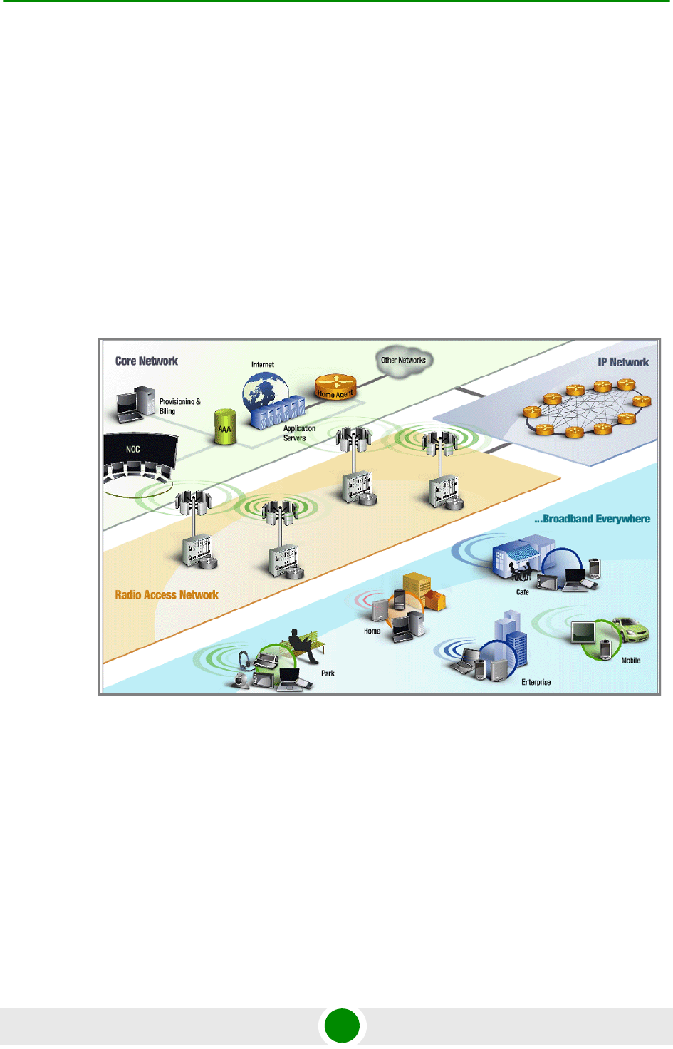
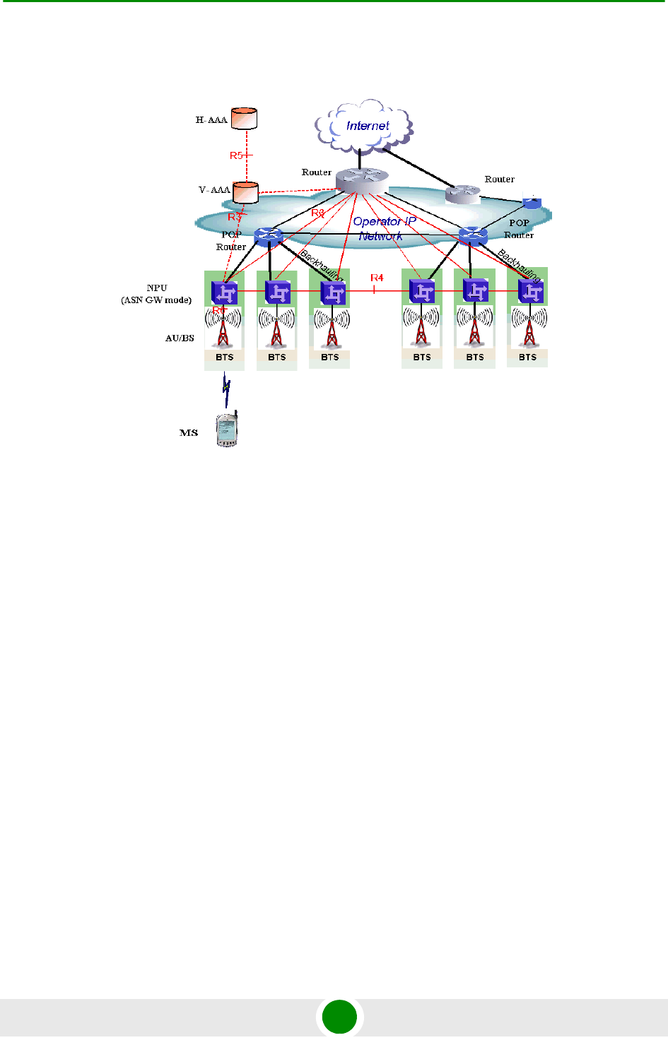
Figure 1-1 illustrates the entire service provider environment and 4Motion
solution elements within the radio access network, core network and subscriber
environment.
Alvarion believes that compliance with standard-driven open architecture protects
the infrastructure investment, and opens the system to a variety of fully
interoperable end-user devices. As such, 4Motion is designed with open
architecture and interfaces according to the WiMAX Forum networking working
group (NWG) profile C, which supports openness and enables flat as well as
hierarchical topologies. In addition, by keeping the radio resource management
functionality in the Base Transceiver Station only, Profile C delivers a faster,
optimized handover mechanism.
Figure 1-1: 4Motion Solution Elements
Chapter 1 - System Description 4Motion Solution
4Motion 6 System Manual
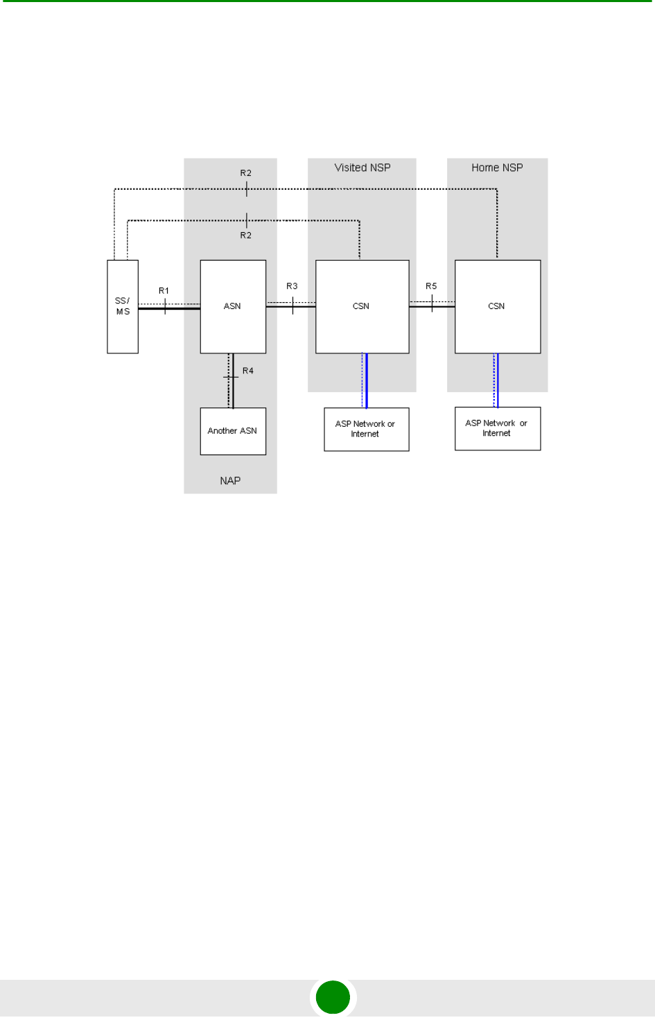
1.2.2 WiMAX Network Reference Model
Figure 1-2 and Figure 1-3 show the basic mobile WiMAX network architecture,
with a single ASN-GW and with multiple ASN-GWs, as defined by the WiMAX
Forum NWG.
Figure 1-2: Mobile WiMAX Network Reference Model
Chapter 1 - System Description 4Motion Solution
4Motion 7 System Manual
The various components and entities involved in the networking architecture are:
1.2.2.1 Access Service Network (ASN)
An ASN is defined as a complete set of network functions needed to provide radio
access to a WiMAX subscriber. The ASN provides the following mandatory
functions:
WiMAX Layer-2 (L2) connectivity with WiMAX mobile station (MS)
Transfer of AAA messages to the WiMAX subscriber's home network service
provider (H-NSP) for authentication, authorization and session accounting for
subscriber sessions
Network discovery and selection of the WiMAX subscriber's preferred NSP
Relay functionality for establishing Layer-3 (L3) connectivity with a WiMAX MS
(i.e. IP address allocation)
Radio resource management
ASN-CSN tunneling
ASN anchored mobility
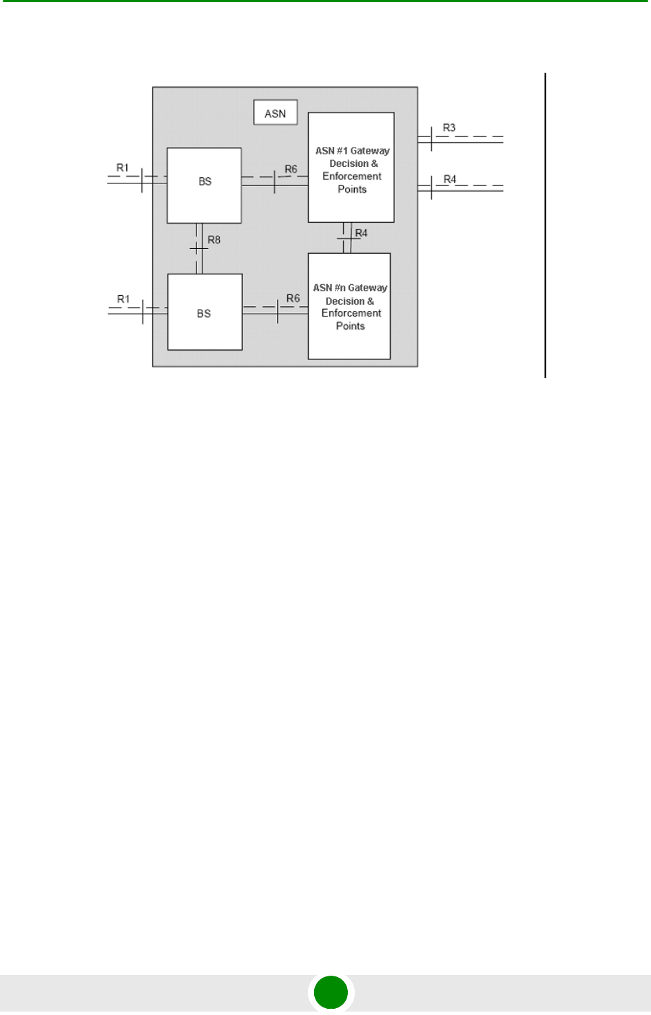
Figure 1-3: ASN Reference Model containing Multiple ASN-GWs

Chapter 1 - System Description 4Motion Solution
4Motion 8 System Manual
An ASN is comprised of network elements such as one or more base transceiver
stations and one or more ASN gateways. An ASN may be shared by more than one
connectivity service network (CSN).
1.2.2.2 Connectivity Service Network (CSN)
A CSN is defined as a set of network functions that provide IP connectivity
services to WiMAX subscribers. A CSN may offer the following functions:
MS IP address and endpoint parameter allocation for user sessions
Internet access
AAA proxy or server
Policy and admission control based on user subscription profiles
ASN-CSN tunneling support
WiMAX subscriber billing and inter-operator settlement
WiMAX services such as location-based services, connectivity for peer-to-peer
services, provisioning, authorization and/or connectivity to IP multimedia
services, and facilities to support lawful intercept services such as those
compliant with Communications Assistance Law Enforcement Act (CALEA)
procedures
A CSN is comprised of network elements such as routers, proxy/servers, user
databases, and inter-working gateway devices.
1.2.2.3 Network Access Provider (NAP)
An NAP is a business entity that provides WiMAX radio access infrastructure to
one or more WiMAX network service providers (NSPs). A NAP implements this
infrastructure using one or more ASNs.
1.2.2.4 Network Service Provider (NSP)
An NSP is a business entity that provides IP connectivity and WiMAX services to
WiMAX subscribers compliant with the established service level agreement. The
NSP concept is an extension of the Internet service provider (ISP) concept,
providing network services beyond Internet access. To provide these services, an
NSP establishes contractual agreements with one or more NAPs. An NSP may also
establish roaming agreements with other NSPs and contractual agreements with

Chapter 1 - System Description 4Motion Solution
4Motion 9 System Manual
third-party application providers (e.g. ASP, ISP) for the delivery of WiMAX services
to subscribers. From a WiMAX subscriber standpoint, an NSP may be classified as
a home or visited NSP.
1.2.2.5 Base Station (BS)
The WiMAX BS is an entity that implements the WiMAX MAC and PHY in
compliance with the IEEE 802.16e standard. A BS operates on one frequency
assignment, and incorporates scheduler functions for uplink and downlink
resources.
The basic functionality of the BS includes:
IEEE 802.16e OFDMA PHY/MAC entity
R6 and R8 functionality according to NWG definitions
Extensible Authentication Protocol (EAP) relay
Control message authentication
User traffic authentication and encryption
Handover management
QoS service flow management entity
1.2.2.6 ASN Gateway (ASN-GW)
The ASN-GW is a network entity that acts as a gateway between the ASN and
CSN. The ASN functions hosted in an ASN-GW may be viewed as consisting of two
groups - the decision point (DP) and enforcement point (EP). The EP includes
bearer plane functions, and the DP includes non-bearer plane functions.
The basic DP functionality of the ASN-GW includes:
Implementation of EAP Authenticator and AAA client
Termination of RADIUS protocol against the selected CSN AAA server (home or
visited AAA server) for MS authentication and per-MS policy profile retrieval
Storage of the MS policy profile
Generation of authentication key material
Chapter 1 - System Description 4Motion Solution
4Motion 10 System Manual
QoS service flow authorization entity
AAA accounting client
The basic EP functionality of the ASN-GW includes:
Classification of downlink data into generic routing encapsulation (GRE)
tunnels
Packet header suppression functionality
DHCP functionality
Handover functionality
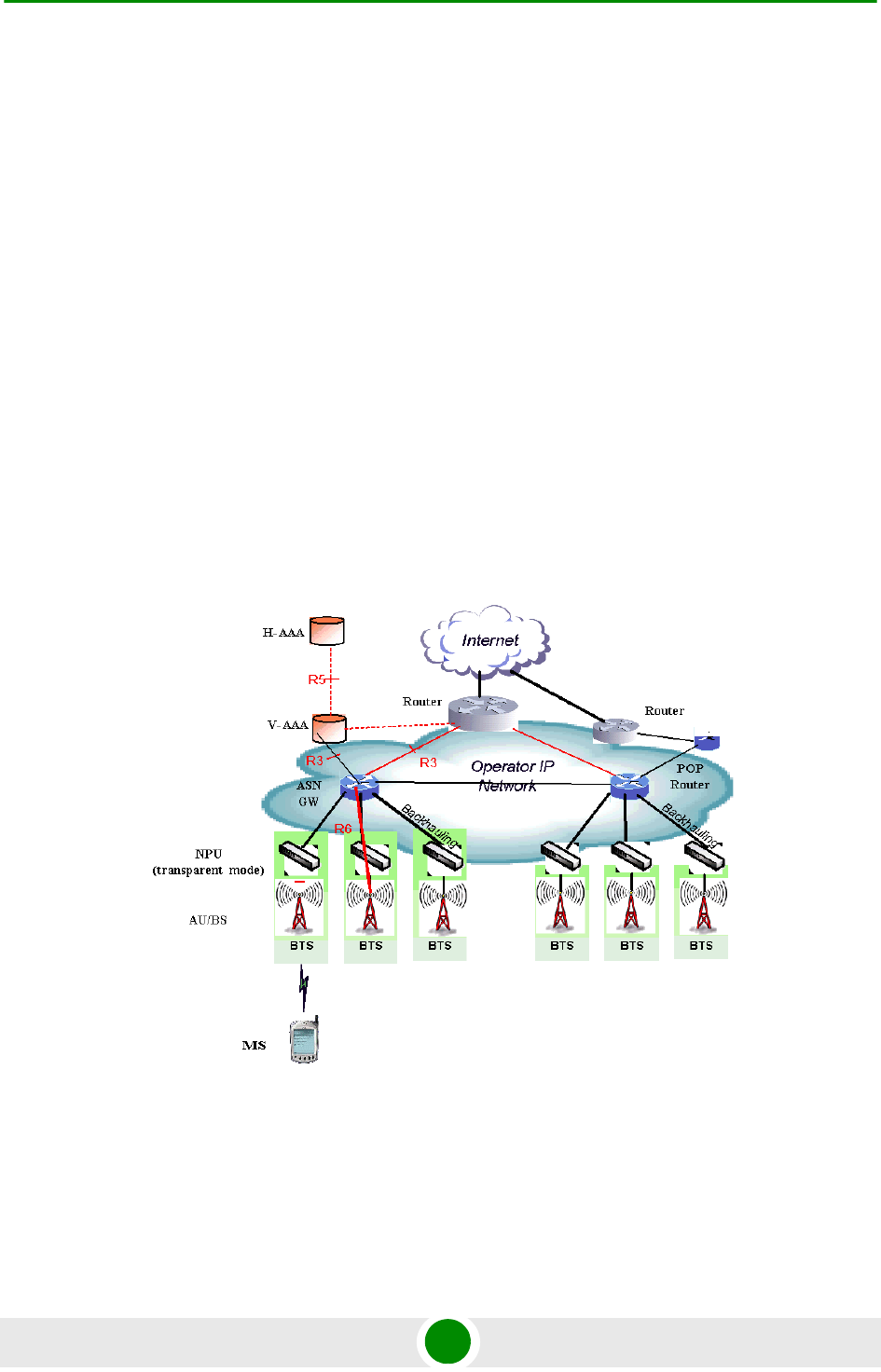
The WIMAX Forum NWG has adopted two different approaches for ASN
architecture - centralized and distributed: In the centralized approach there is at
least one central ASN-GW, and the BTS NPU operates in transparent mode, as
shown in Figure 1-4.
Figure 1-4: Centralized Network Reference Model
Chapter 1 - System Description 4Motion Solution
4Motion 11 System Manual
In the distributed approach, the BTS NPU operates in ASN-GW mode, as shown in
Figure 1-5.
Alvarion believes in providing operators with the flexibility to select the mobile
WiMAX network topology that best suits their needs and existing network
architecture. Therefore, 4Motion is designed to support both distributed and
centralized topology approaches according to WiMAX Forum NWG profile C.
1.2.2.7 Reference Points
Reference point R1 consists of the protocols and procedures between the MS
and ASN as per the air-interface (PHY and MAC) specifications (IEEE 802.16e).
Reference point R2 consists of protocols and procedures between the MS and
CSN associated with authentication, services authorization and IP host
configuration management. This reference point is logical in that it does not
reflect a direct protocol interface between the MS and CSN. The authentication
part of reference point R2 runs between the MS and CSN operated by the
home NSP, however, the ASN and CSN operated by the visited NSP may
partially process the aforementioned procedures and mechanisms. Reference
point R2 might support IP host configuration management running between
the MS and CSN (operated by either the home NSP or visited NSP).
Figure 1-5: Distributed Network Reference Model

Chapter 1 - System Description 4Motion Solution
4Motion 12 System Manual
Reference point R3 consists of the set of control plane protocols between the
ASN and CSN to support AAA, policy enforcement and mobility management
capabilities. It also encompasses the bearer plane methods (e.g. tunneling) to
transfer user data between the ASN and CSN.
Reference point R4 consists of the set of control and bearer plane protocols
originating/terminating in various functional entities of an ASN that
coordinate MS mobility between ASNs and ASN-GWs. R4 is the only
interoperable reference point between similar or heterogeneous ASNs.
Reference point R5 consists of the set of control plane and bearer plane
protocols for internetworking between the CSN operated by the home NSP and
that operated by a visited NSP.
Reference point R6 consists of the set of control and bearer plane protocols
for communication between the BS and ASN-GW. The bearer plane consists of
an intra-ASN data path between the BS and ASN gateway. The control plane
includes protocols for data path establishment, modification and release
control in accordance with the MS mobility events.
Reference point R8 consists of the set of control plane message flows and
optional bearer plane data flows between the base stations to ensure a fast
and seamless handover. The bearer plane consists of protocols that allow data
transfer between base stations involved in the handover of a certain MS.
It is important to note that all reference points are logical and do not necessarily
imply a physical or even direct connection. For instance, the R4 reference point
between ASN-GWs might be implemented across the NAP internal transport IP
network, in which case R4 traffic might traverse several routers from the source to
the destination ASN-GW.

Chapter 1 - System Description The Base Transceiver Station
4Motion 13 System Manual
1.3 The Base Transceiver Station
The 4Motion solution features a multi-carrier, high-power Base Transceiver
Station (BTS). Designed for high availability and redundancy, it utilizes a central
networking and management architecture, and a range of diversity schemes.
The BTS main features include:
R1 support - 802.16e interface handling (e.g. PHY, MAC, CS, Scheduler, ARQ)
and processes such as handover, power control and network entry
R6 support - communication with ASN-GW
EAP proxy in ASN-GW mode
Handover triggering for mobility tunnel establishment - R6 (GRE tunnel)
Local QoS PEP for traffic via air interface (or SFM) and admission control
Hand-Over (HO) control function
Radio resource management agent
Key generation (TEK, KEK) and traffic encryption
The 4Motion Base Transceiver Station includes the modular BreezeMAX shelf,
Outdoor Radio Units, GPS Receiver and other components.
1.3.1 The BreezeMAX Shelf
The BreezeMAX shelf is an indoor -48 VDC powered 8U cPCI PICMG 2.x standard
shelf prepared for installation in a 19" or 21" (ETSI) rack. This chassis has a total
of nine double-Euro (6U high) slots and six single-Euro (3U high) slots. All the
Chapter 1 - System Description The Base Transceiver Station
4Motion 14 System Manual
modules are hot swappable, and high availability can be provided through
multiple redundancy schemes.
The shelf modules are:
The six single-Euro slots are intended for one or two redundant Power Interface
Units (PIUs) and up to four redundant Power Supply Units (PSUs). One of the
double Euro slots is dedicated to the NPU module, with interfaces for network
backhaul, in-band and out-of-band (OOB) management connections. Another
double-Euro slot is reserved for an optional redundant NPU (the shelf is HW-ready
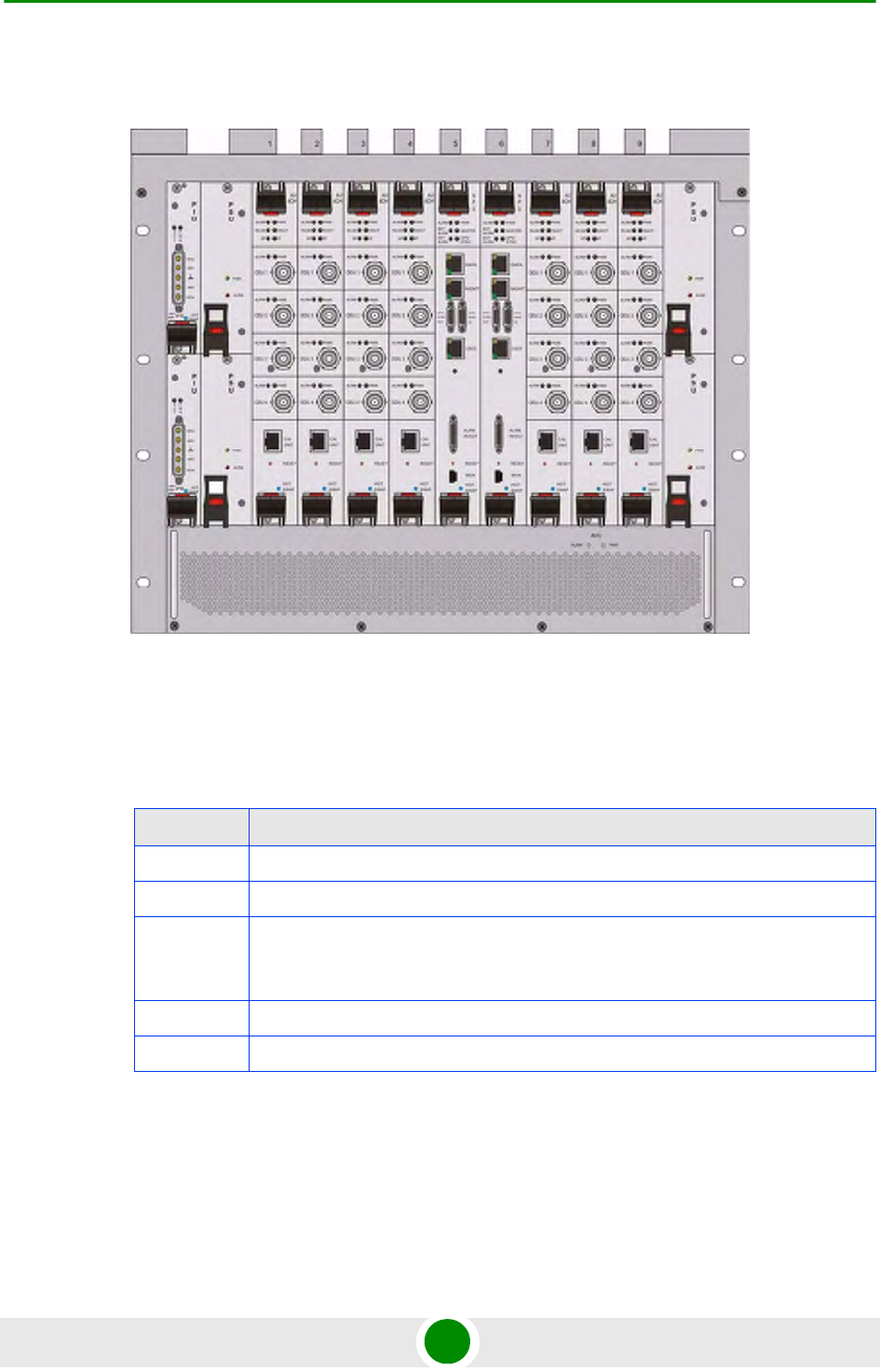
Figure 1-6: BreezeMAX Shelf (with all modules installed)
Table 1-1: BreezeMAX Shelf Modules
Module Description
PIU 3U high power interface unit, 1+1 redundancy, -48VDC, protection, filters
PSU 3U high power supply unit, up to 3+1 redundancy
NPU 6U high network processing unit with optional ASN-GW functionality, hardware
ready for 1+1 redundancy, 1000/100 Base-T main network interface, 1000/100
Base-T cascade interface and 100/10 Base-T out-of-band management interface
AU 6U high access unit, 4-channel, 802.16e MAC-modem-baseband IF card
AVU 2U high air ventilation unit, 9+1 redundancy fans with alarm control

Chapter 1 - System Description The Base Transceiver Station
4Motion 15 System Manual
for NPU redundancy). The remaining seven double-Euro slots are dedicated for
Access Unit (AU) modules, thereby enabling various network topologies and future
redundancy configurations. In addition, the shelf contains an Air Ventilation Unit
(AVU).
1.3.2 NPU
The Network Processing Unit is the controller of the Base Transceiver Station.
Serving as the central processing unit that manages the BTS components, the
NPU aggregates traffic to/from the AU modules, and transfers it to/from the IP
backbone through a dedicated Gigabit/Fast Ethernet interface. In addition, the
NPU can be operated in ASN-GW mode, in which case it also implements ASN-GW
functionality.
When operating in ASN-GW mode, the NPU implements the R3 reference point
toward the CSN, R4 reference point toward other ASN-GWs, and R6 reference
point toward AU/BSs. The R8 reference point traffic is transparently relayed
between AU/BSs (intra- or inter-BTS).
When operating in transparent mode, the NPU transparently relays R6 and R8
reference-point traffic between AU/BSs (intra- or inter-BTS).
The BreezeMAX shelf is hardware-ready for 1+1 NPU card redundancy.
The NPU main functions, when operating in transparent mode, are:
Aggregate backbone Ethernet connectivity for user and control traffic
Aggregate backbone Ethernet connectivity for management traffic (in-band or
out-of-band)
Connection to a cascaded shelf (future feature)
L2 switch forwarding capabilities
Internal and external traffic VLAN encapsulation
QoS marking
Overall operation, control and shelf management, including AU diagnostics
and control, PSU monitoring, AVU management and redundancy support
Local and remote extensive management support via CLI (Telnet, SSH) and
SNMP, including software download, fault and performance management

Chapter 1 - System Description The Base Transceiver Station
4Motion 16 System Manual
Alarm management, including external alarm inputs and activation of external
devices
Synchronization, including GPS receiver interface, clock and IF reference
generation and distribution to the shelf modules, and holdover handling
Security functionalities such as rate limiting and access control lists
When operating in ASN-GW mode, the following additional ASN-GW functions are
supported:
EAP authenticator
RADIUS AAA client
AAA accounting client
MS policy profile storage
QoS service flow authorization
Classification of downlink data into service flows
Packet header suppression functionality
Multiple service provider support (multihost) for improved security and
wholesale model
DHCP functionality - internal server, DHCP proxy, DHCP relay (with Option 82
support)
Handover functionality
GRE encapsulation/decapsulation
IP-in-IP encapsulation/decapsulation
Transparent VLAN (single tag) and QinQ (dual tag) encapsulation
Fragmentation/reassembly
R4/R6/R3 interfaces implementation

Chapter 1 - System Description The Base Transceiver Station
4Motion 17 System Manual
Keep-alive signaling towards the BS for enhanced service availability.
When several shelves are collocated, the NPU cascade interface can be used for
shelf interconnection. In this architecture, the NPU that is directly connected to
the backhaul implements a layer-2 connection toward the NPUs in the cascaded
shelves. Bearer, control and management traffic is sent over the cascade
connection. Synchronization and GPS backup power are sent toward the NPUs in
the cascaded shelves through the GPS/SYNC ports.
GPS synchronization cascading will be implemented in a future release.
1.3.3 AU
The Access Unit module performs the WiMAX/IEEE 802.16e BS function
according to the NWG Profile C definitions via digital signal processors (DSPs) and
field-programmable gate array (FPGA) technology. The AU module is designed to
support high-traffic throughput and enable diversity, MIMO and AAS, thereby
extending capacity and range.
The AU implements the following functionality:
802.16e multi-channel OFDMA PHY
Up to four-channel support (Tx/Rx)
Diversity and future AAS
Flexible channel bandwidth - up to 20 MHz
Flexible FFT size - up to 2048 points
Wide variety of reuse patterns
Advanced channel coding (CTC)
HARQ
Rate adaptation
High-performance CDMA detector
IF interface to RF ODU
MAC-PHY interface

Chapter 1 - System Description The Base Transceiver Station
4Motion 18 System Manual
Link management (network entry, basic capabilities negotiation,
authentication and registration, connection management)
Fragmentation/ reassembly
QoS PEP for air interface traffic
QoS DSCP marking
Scheduling - connections quota computation for all data delivery types
Frame/burst building
Power save
Handover management
Power control
R1/R6/R8 functionality
Data path mapping between R6 (GRE) and 802.16e interfaces
Traffic authentication and encryption
Authentication relay
Security key receiver
Context client/server
ID to IP address resolution for ASN entities
IP and Ethernet convergence sublayers
Keep-alive signaling towards the ASN-GW for enhanced service availability.
The AU design is based on Alvarion's programmable, off-the-shelf, cutting-edge
components, in order to provide a future-proof solution with excellent cost and
performance.
The AU card interfaces with the NPU card for R6/R8 functionality, as well as
control, synchronization and management between the NPU and AU.

Chapter 1 - System Description The Base Transceiver Station
4Motion 19 System Manual
The AU implements four receive and transmit channels, each of them is HW-ready
for up to 20 MHz bandwidth.
1.3.4 PIU
The single-Euro Power Interface Unit module serves as the interface between the
DC power source and both the PSU modules and external ODU radio transceivers.
The PIU filters and stabilizes the input power, and protects the system from power
problems such as over-voltage, surge pulses, reverse polarity connection, and
short circuits. It filters high-frequency interference (radiated emissions) and
low-frequency interference (conducted emissions) at the external power source.
Each shelf contains two slots for optional 1+1 PIU redundancy. One PIU is
sufficient to support a fully populated shelf, and two modules provide redundant
power feeding (i.e. from two input sources), while avoiding current flow between
the two input sources.
1.3.5 PSU
The single-Euro Power Supply Unit module is a -48 VDC power supply unit that
generates low-voltage DC output to comply with PICMG 2.x standard
requirements. Each shelf can contain up to four PSU modules supporting N+1
redundancy configuration scheme.
Table 1-2 displays the number of PSU modules (excluding redundant units)
required for various Base Station configurations without NPU redundancy (one
NPU):
1.3.6 AVU
The 2U-high AVU includes a 1U-high integral chamber for inlet airflow and a
1U-high fan tray with an internal alarm module. To support high availability, the
fan tray includes 10 brushless fans (9 fans are sufficient for cooling a fully-loaded
shelf). Fan failure is indicated by both the front panel LEDs and a trap sent to the
management system. To further support high availability, the chassis may
operate without the hot-swappable fan tray for up to 10 minutes until the AVU is
replaced.
Table 1-2: PSU Requirements, Configurations with one NPU (excluding PSU
redundancy)
Number of AUs Minimum Required Number of PSUs
1 - 4 2
5 - 6 3

Chapter 1 - System Description The Base Transceiver Station
4Motion 20 System Manual
1.3.7 ODU
The outdoor unit (ODU) is a high-power, multi-carrier radio unit that connects to
one or more external antennas. It is designed to provide high system gain and
interference robustness utilizing high transmit power and low noise figure. It is
HW-ready for supporting a bandwidth of up to 20 MHz, enabling future options
such as increased capacity through the use of a multiplexer or wider frequency
channels.
The following ODU port configurations will be available:
1x1(1Rx by 1 Tx): One receive port, one transmit port
2x1 (2Rx by 1Tx): Two receive ports, one transmit port
4x2 (4Rx by 2Tx): Four receive ports, two transmit ports
In the current release only 1x1 and 4x2 ODUs are available.
The wide range of ODU types will enable efficient utilization of various second and
fourth order transmit and receive diversity schemes.
The following table provides details on the currently available ODUs following the
WiMAX Forum’s definitions:

Chapter 1 - System Description The Base Transceiver Station
4Motion 21 System Manual
1.3.8 Power Feeder
The PIU can support a maximum current of 58 A (@-40.5 VDC). In certain
installations with a relatively high number of ODUs this current may not be
sufficient to power the shelf and all the ODUs. In such installations the ODU
Power Feeder is used as an additional power source providing power (-48 VDC) to
ODUs. It transfers transparently all signals between the AU and the ODU, while
injecting DC power received from an external source. Each ODU Power Feeder
unit can serve up to four ODUs. Up to three ODU Power Feeder units can be
installed in a 1U high Power Feeder panel.
1.3.9 Antenna
In the 4Motion architecture, the antenna is approached as an independent
element. This provides the operator with the flexibility to select the antennas
source according to its supplier policy. To ensure the availability of antennas that
complement the 4Motion solution, Alvarion works closely with several antenna
suppliers to ensure availability of antennas that comply with its requirements.
In cases where the operator prefers other antenna vendors, Alvarion can provide a
recommended antenna specification based on the required antennas types.
For more information on recommended antenna configurations and required
antennas refer to “Antenna Configurations” on page 836.
Table 1-3: ODU Types
Band (GHz) ODU Frequency Range
(MHz) ODU Port
Configuration ODU Bandwidth
(MHz) ODU Max Tx
Power (dBm)
2.3 2300-2360 1Rx by 1Tx Up to 10 36
2.5 2496-2602 (band A) 1Rx by 1Tx Up to 10 36
2590-2690 (band B) 1Rx by 1Tx Up to 10 36
2496-2602 (band A) 4Rx by 2Tx Up to 20 38
2590-2690 (band B) 4Rx by 2Tx Up to 20 38
3.x 3400-3455 1Rx by 1Tx Up to 14 34
3445-3500 1Rx by 1Tx Up to 14 34
3500-3555 1Rx by 1Tx Up to 14 34
3545-3600 1Rx by 1Tx Up to 14 34
3400-3600 4Rx by 2Tx Up to 20 37

Chapter 1 - System Description The Base Transceiver Station
4Motion 22 System Manual
1.3.10 GPS
GPS is used to synchronize the air link frames of Intra-site and Inter-site located
Base Transceiver Stations to ensure that in all Base Stations the air frame will
start at the same time, and that all Base Stations will switch from transmit
(downlink) to receive (uplink) at the same time. This synchronization is necessary
to prevent Intra-site and Inter-site interference and Base stations saturation
(assuming that all Base Stations are operating with the same frame size and with
the same DL/UL ratio).
In order for the system to be synchronized, the GPS have to first acquire at least 4
satellites. After that the GPS reception can be reduced to 1 satellite.If no satellite
is received the BTS will go to holdover state where internal clock is provided to
synchronize the BTS.
1.3.10.1 Outdoor GPS Receiver
The all-outdoor GPS Receiver is a pole mountable GPS receiver and antenna in a
single environmentally protected enclosure. The GPS Receiver is powered by a 12
VDC power source, supplied to it by the NPU. The RS-422 interface allows
installation at distances up to 100m.

Chapter 1 - System Description Element Management Systems
4Motion 23 System Manual
1.4 Element Management Systems
The end-to-end IP-based architecture of the system enables full management of
all components, using standard management tools. An SNMP agent in the NPU
implements proprietary MIBs for remote setting of operational modes and
parameters of the Base Transceiver Station equipment. Security features
incorporated in the equipment restrict the access for management purposes.
Alvarion offers the following management tool:
1.4.1 AlvariSTAR™
AlvariSTAR is a comprehensive carrier-class Element Management System (EMS)
for Alvarion’s Broadband Wireless Access systems. AlvariSTAR is designed for
today's most advanced Network Operation Centers (NOCs), providing the network
Operation, Administration and Maintenance (OA&M) staff and managers with all
the network surveillance, monitoring and configuration and service provisioning
capabilities required to effectively manage the network while keeping the
resources and expenses at a minimum.
AlvariSTAR offers the network's OA&M staff with a unified, scalable and
distributable management system. Utilizing distributed client-server architecture,
the user is provided with a robust, scalable and fully redundant management
system in which all single points of failure can be avoided.
AlvariSTAR provides the following management functionality:
Device Discovery
Device Inventory
Topology
Fault Management
Configuration Management
Service Management
Data Collection
Performance Monitoring

Chapter 1 - System Description Element Management Systems
4Motion 24 System Manual
Device embedded software upgrade
Security Management
Error Forwarding to other Network Management Systems.

Chapter 1 - System Description Specifications
4Motion 25 System Manual
1.5 Specifications
1.5.1 Modem & Radio
1.5.2 Sensitivity
Table 1-4: General Modem & Radio Specifications
Item Description
Operation Mode TDD
Channel Bandwidth 5 MHz
7 MHz
10 MHz
Central Frequency Resolution 0.125 MHz (actual configurable frequencies depend on the
local radio regulations and allocated spectrum)
Modulation OFDM modulation, 1024/512 FFT points;
QPSK, QAM16, QAM64
Access Method OFDMA
FEC Convolutional Turbo Coding: 1/2, 2/3, 3/4, 5/6
Table 1-5: Sensitivity, AWGN @ PER=1%
Modulation
& Coding Sensitivity (dBm),
5 MHz Bandwidth Sensitivity (dBm),
7 MHz Bandwidth Sensitivity (dBm),
10 MHz Bandwidth
QPSK 1/2 -97.3 -95.8 -94.2
QPSK 3/4 -94.9 -93.4 -91.8
16QAM 1/2 -92.2 -90.7 -89.1
16QAM 3/4 -88.3 -86.8 -85.2
64QAM1/2 -86.8 -85.3 -83.7
64QAM2/3 -83.0 -81.5 -79.9
64QAM3/4 -82.2 -80.7 -79.1
64QAM5/6 -81.0 -79.5 -77.9

Chapter 1 - System Description Specifications
4Motion 26 System Manual
1.5.3 ODUs
1.5.3.1 2.3 GHz Band
Table 1-6: 1x1 ODU-HP-2.3 Specifications
Item Description
Frequency Band 2300-2360 MHz
Ports Configuration 1x1 (1Rx, 1Tx)
Bandwidth Support Up to 10 MHz, 5 & 10 MHz SAW filters
Maximum Tx Power ) 36 dBm
Tx Power Control Range 6 dB, in 1 dB steps
Tx Power Accuracy +/- 1 dB
Maximum Input Power @ antenna port -60 dBm before saturation, -8 dBm before damage
Noise Figure 4.6 dB typical, 6.0 dB maximum
Dimension 329 x 157 x 169 mm
Weight 6.1 Kg
Connectors ANT: N-Type jack, 50 Ohm, lightning protected
IF: TNC jack, 50 Ohm, lightning protected
Power Source -40.5 to -60 VDC over the IF cable
Power Consunption Transmit - 89W maximum, 75W typical
Receive - 15W maximum, 9W typical

Chapter 1 - System Description Specifications
4Motion 27 System Manual
1.5.3.2 2.5 GHz Band
Table 1-7: 2.5 GHz Band 1x1 ODUs Specifications
Item Description
Frequency Band ODU-HP-2.5A: 2496-2602 MHz (Band A)
ODU-HP-2.5B: 2590-2690 MHz (Band B)
Ports Configuration 1x1 (1Rx, 1Tx)
Bandwidth Support Up to 10 MHz
Maximum Tx Power ) 36 dBm
Tx Power Control Range 6 dB, in 1 dB steps
Tx Power Accuracy +/- 1 dB
Maximum Input Power @
antenna port
-60 dBm before saturation, -8 dBm before damage
Noise Figure 4.6 dB typical, 6.0 dB maximum
Dimension 329 x 157 x 209 mm
Weight 6.1 Kg
Connectors ANT: N-Type jack, 50 Ohm, lightning protected
IF: TNC jack, 50 Ohm, lightning protected
Power Source -40.5 to -60 VDC over the IF cable
Power Consunption Transmit - 89W maximum, 75W typical
Receive - 15W maximum, 9W typical

Chapter 1 - System Description Specifications
4Motion 28 System Manual
Table 1-8: 2.5 GHz Band 4x2 ODUs Specifications
Item Description
Frequency Band ODU-2496-2602-000N-38-4x2-N-0: 2496-2602 MHz (Band A)
ODU-2590-2690-000N-38-4x2-N-0: 2590-2690 MHz (Band B)
ODU-2483-2493-000N-38-4x2-N-0: 2483.5-2493.5 MHz
ODU-2596-2690-000N-38-4x2-N-0: 2596-2690 MHz
Ports Configuration 4x2 (4Rx, 2Tx)
Bandwidth Support Up to 20 MHz
Maximum Tx Power ) ODU-2483-2493: 37 dBm
Other ODUs: 38 dBm
Tx Power Control Range 10 dB, in 1 dB steps
Tx Power Accuracy +/- 1 dB
Maximum Input Power @
antenna port
-60 dBm before saturation, -8 dBm before damage
Noise Figure 4.5 dB typical, 5.5 dB maximum
Dimension 420 x 340 x 270 mm
Weight 15 Kg
Connectors ANT: 4 x N-Type jack, 50 Ohm, lightning protected
IF: 4 x TNC jack, 50 Ohm, lightning protected
Power Source -40.5 to -60 VDC over the IF cable
Power Consunption Transmit - 284W maximuml
Receive - 70W maximum

Chapter 1 - System Description Specifications
4Motion 29 System Manual
1.5.3.3 3.x GHz Band
Table 1-9: 3.x GHz Band 1x1 ODUs Specifications
Item Description
Frequency Band ODU-HP-TDD-3.4a: 3400-3455 MHz
ODU-HP-TDD-3.4b: 3445-3500 MHz
ODU-HP-TDD-3.5a: 3500-3555 MHz
ODU-HP-TDD-3.5b: 3545-3600 MHz
Ports Configuration 1x1 (1Rx, 1Tx)
Bandwidth Support Up to 14 MHz
Maximum Tx Power 34 dBm
Tx Power Control Range 10 dB, in 1 dB steps
Tx Power Accuracy +/- 1 dB
Maximum Input Power @
antenna port
-60 dBm before saturation, -8 dBm before damage
Noise Figure 4.5 dB typical, 5.5 dB maximum
Dimension 329 x 157 x 169 mm
Weight 6.1 Kg
Connectors ANT: N-Type jack, 50 Ohm, lightning protected
IF: TNC jack, 50 Ohm, lightning protected
Power Source -40.5 to -60 VDC over the IF cable
Power Consunption Transmit - 90W maximum, 62W typical
Receive - 20W maximum, 14W typical

Chapter 1 - System Description Specifications
4Motion 30 System Manual
Table 1-10: 3.x GHz Band 4x2 ODUs Specifications
Item Description
Frequency Band ODU-3400-3600-000N-37-4x2-N-0: 3400-3600 MHz
Ports Configuration 4x2 (4Rx, 2Tx)
Bandwidth Support Up to 20 MHz
Maximum Tx Power ) 37 dBm
Tx Power Control Range 10 dB, in 1 dB steps
Tx Power Accuracy +/- 1 dB
Maximum Input Power @
antenna port
-60 dBm before saturation, -8 dBm before damage
Noise Figure 4.5 dB typical, 5.5 dB maximum
Dimension 420 x 340 x 270 mm
Weight 15 Kg
Connectors ANT: 4 x N-Type jack, 50 Ohm, lightning protected
IF: 4 x TNC jack, 50 Ohm, lightning protected
Power Source -40.5 to -60 VDC over the IF cable
Power Consunption Transmit - 216W maximuml
Receive - 24W maximum

Chapter 1 - System Description Specifications
4Motion 31 System Manual
1.5.4 AU - ODU Communication
1.5.5 Data Communication (Ethernet Interfaces)
Table 1-11: AU - ODU Communication
Item Description
IF Frequency Tx: 240 MHz
Rx: 140 MHz
Ref Synchronization Frequency 64 MHz
Bi-Directional Control Frequency 14 MHz
IF cable Impedance 50 Ohm
Maximum IF cable Attenuation 10 dB @ 240 MHz
7.5 dB @ 140 MHz
8 dB @ 64 MHz
Minimum IF cable Shielding Effectiveness 90 dB in the 10-300 MHz band
Maximum IF cable Return Loss 20 dB in the 10-300 MHz band
Maximum IF cable DC Resistance 1x1 ODUs, 2.x GHz 4x2 ODUs: 1.5 Ohm
3.x GHz 4x2 ODUs: 1 Ohm
Table 1-12: Data Communication (Ethernet Interfaces)
Item Description
Standard Compliance IEEE 802.3 CSMA/CD
Speed NPU Data Port 100/1000 Mbps, Full Duplex with Auto Negotiation
NPU Management Port 10/100 Mbps, Half/Full Duplex with Auto Negotiation
NPU Cascade Port 100/1000 Mbps, Full Duplex with Auto Negotiation
AU Calibration Port 10/100 Mbps, Half/Full Duplex with Auto Negotiation

Chapter 1 - System Description Specifications
4Motion 32 System Manual
1.5.6 Configuration and Management
Table 1-13: Configuration and Management
Item Description
Out Of Band (OOB) Management Telnet via Management port
SSH via Management port
SNMP via Management port
Telnet via Cascade port
SSH via Cascade port
SNMP via Cascade port
Monitor port (serial interface)
In Band (IB) Management via Data Port SNMP
Telnet
SSH
SNMP Agents SNMP ver 2 client
MIB II (RFC 1213), Private MIBs
Software Upgrade Using TFTP
Configuration Upload/Download Using TFTP

Chapter 1 - System Description Specifications
4Motion 33 System Manual
1.5.7 Standards Compliance, General
1.5.8 Environmental
Table 1-14: Standards Compliance, General
Type Standard
EMC ETSI EN 301 489-1/4
Safety EN60950-1 (CE)
UL 60950-1 US/C (TUV)
Environmental ETS 300 019:
Part 2-1 T 1.2 & part 2-2 T 2.3 for indoor & outdoor
Part 2-3 T 3.2 for indoor
Part 2-4 T 4.1E for outdoor
Radio ETSI EN 302 326
FCC part 15, part 27
Table 1-15: Environmental Specifications
Type Unit Details
Operating
Temperature
Outdoor units ODUs: -40°C to 55°C
Outdoor GPS Receiver: -40°C to 85°C
Indoor equipment 0°C to 40°C
Operating
Humidity
Outdoor units 8%-100%, weather protected
Indoor equipment 5%-95% non condensing

Chapter 1 - System Description Specifications
4Motion 34 System Manual
1.5.9 Mechanical and Electrical
1U = 44.45 mm (1.75”).
1HP = 5.08 mm (0.2”)
1.5.9.1 BreezeMAX Shelf
1.5.9.2 AVU
1.5.9.3 PIU
Table 1-16: BreezeMAX Shelf, Mechanical & Electrical Specifications
Item Description
Dimensions 8U ETSI type shelf, 8U x 43.2 x 24 cm
Weight 6.9 Kg (excluding AVU)
Table 1-17: AVU, Mechanical & Electrical Specifications
Item Description
Dimensions 2U x 84HP x 16 cm
Weight 1.5 Kg
Power Condumption 40W maximum, 23W typical
Table 1-18: PIU, Mechanical & Electrical Specifications
Item Description
Dimensions 3U x 5HP x 16 cm
Weight 0.45 Kg
Power Source -40.5 to -60 VDC
Power Dissipation 35W maximum (active PIU)
Maximum Supplied Current 58A
-48V Connector 5 pin/40A D-Type plug

Chapter 1 - System Description Specifications
4Motion 35 System Manual
1.5.9.4 PSU
1.5.9.5 NPU
1.5.9.6 AU
Table 1-19: PSU, Mechanical & Electrical Specifications
Item Description
Dimensions 3U x 5HP x 16 cm
Weight 0.7 Kg
Power Output 300W maximum output power
Efficiency: 80% minimum
Table 1-20: NPU, Mechanical & Electrical Specifications
Item Description
Dimensions 6U x 7HP x 16 cm
Weight 0.7 Kg
Power Consumption 68W maximum, 61W typical
Connectors DATA 100/1000Base-T (RJ-45) with 2 embedded LEDs
MGMT 10/100Base-T (RJ-45) with 2 embedded LEDs
GPS/SYNC IN 15-pin micro D-Type jack
GPS/SYNC OUT 15-pin micro D-Type jack
CSCD 100/1000Base-T (RJ-45) with 2 embedded LEDs
ALRM IN/OUT 25-pin micro D-Type jack
MON 3-pin low profile jack
Table 1-21: AU, Mechanical & Electrical Specifications
Item Description
Dimensions 6U x 7HP x 16 cm
Weight 0.6 Kg
Power Consumption 74W maximum, 66W typical
Connectors ODU1 - ODU4 4 x TNC jack, lightning protected
CAL UNIT 10/100Base-T (RJ-45) with 2 embedded LEDs

Chapter 1 - System Description Specifications
4Motion 36 System Manual
1.5.9.7 GPS Receiver
1.5.9.8 ODU Power Feeder
Table 1-22: GPS Receiver, Mechanical & Electrical Specifications
Item Description
Dimensions Tubular enclosure, 15.5 D x 12.7 H cm
Weight 0.363 Kg
Power Source 12 VDC from the NPU
Power Consumption 6W maximum
Connector 12-pin round plug
Table 1-23: ODU Power Feeder, Mechanical & Electrical Specifications
Item Description
Dimensions 15.7 x 14.6 x 3.17 cm
Weight 0.6 Kg
Power Source -40.5 to -60 VDC
Power Dissipation 2W per channel
Connectors ODU 1 - ODU 4 4 x TNC jack, lightning protected
IDU 1 - IDU 4 4 x TNC jack, lightning protected
Power 3 pin/20A D-Type plug

Chapter 1 - System Description Specifications
4Motion 37 System Manual
1.5.10 Antennas
1.5.10.1 2.x GHz Antennas
Table 1-24: BS-RET-DP-ANT 2.3-2.7 Specifications
Item Description
Frequency Band (MHz) 2300-2700
Number of Elements 2
Polarization Linear, +/-45°
Gain (dB) 17.3 @ 2.4 GHz
18 @ 2.6 GHz
Azimuth Beamwidth (degrees) 65
Elevation Beamwidth (degrees) 6.5
Elevation Side Lobe Level (dB) <-18
Maximum Power (W) 250
Cross-polarization Discrimination (dB) >15
Front-to-Back Ratio (dB) >30
Electrical Downtilt Range (degrees) 0-10
Remote Electrical Downtilt Support Internal motor, AISG version 2 compliant
Isolation Between Ports (dB) >30
Return Loss (dB) >15
RF Interface Impedance (Ohm) 50
RF Connectors 2 x N-Type jack
RET Connector 8-pin IEC 60130-9
Dimensions (mm) 1060 x 126 x 69
Weight (Kg) 6
Wind Load (Kg) 0.24 @ 160 km/h
Maximum Wind Velocity (km/h) 200

Chapter 1 - System Description Specifications
4Motion 38 System Manual
Table 1-25: BS-RET-DDP-ANT 2.3-2.7 Specifications
Item Description
Frequency Band (MHz) 2300-2700
Number of Elements 4
Polarization Linear, 2 x +/-45°
Gain (dB) 17.3 @ 2.4 GHz
18 @ 2.6 GHz
Azimuth Beamwidth (degrees) 65
Elevation Beamwidth (degrees) 6.5
Elevation Side Lobe Level (dB) <-18
Maximum Power (W) 250
Cross-polarization Discrimination (dB) >15
Front-to-Back Ratio (dB) >30
Electrical Downtilt Range (degrees) 0-10
Remote Electrical Downtilt Support Internal motor, AISG version 2 compliant
Isolation Between Ports (dB) >30
Return Loss (dB) >15
RF Interface Impedance (Ohm) 50
RF Connectors 4 x N-Type jack
RET Connector 8-pin IEC 60130-9
Dimensions (mm) 1070 x 300 x 110
Weight (Kg) 13
Wind Load (Kg) 0.48 @ 160 km/h
Maximum Wind Velocity (km/h) 200

Chapter 1 - System Description Specifications
4Motion 39 System Manual
1.5.10.2 3.5 GHz Antennas
Table 1-26: BS-RET-DP-ANT 3.3-3.8 Specifications
Item Description
Frequency Band (MHz) 3300-3800
Number of Elements 2
Polarization Linear, +/-45°
Gain (dB) 18
Azimuth Beamwidth (degrees) 65
Elevation Beamwidth (degrees) 6.5
Elevation Side Lobe Level (dB) <-18
Maximum Power (W) 200
Cross-polarization Discrimination (dB) >15
Front-to-Back Ratio (dB) >30
Electrical Downtilt Range (degrees) 0-10
Remote Electrical Downtilt Support Internal motor, AISG version 2 compliant
Isolation Between Ports (dB) >30
Return Loss (dB) >15
RF Interface Impedance (Ohm) 50
RF Connectors 2 x N-Type jack
RET Connector 8-pin IEC 60130-9
Dimensions (mm) 760 x 126 x 69
Weight (Kg) 4.5
Wind Load (Kg) 0.17@ 160 km/h
Maximum Wind Velocity (km/h) 200

Chapter 1 - System Description Specifications
4Motion 40 System Manual
Table 1-27: BS-RET-DDP-ANT 3.3-3.8 Specifications
Item Description
Frequency Band (MHz) 3300-3800
Number of Elements 4
Polarization Linear, 2 x +/-45°
Gain (dB) 18
Azimuth Beamwidth (degrees) 65
Elevation Beamwidth (degrees) 6.5
Elevation Side Lobe Level (dB) <-18
Maximum Power (W) 200
Cross-polarization Discrimination (dB) >15
Front-to-Back Ratio (dB) >30
Electrical Downtilt Range (degrees) 0-10
Remote Electrical Downtilt Support Internal motor, AISG version 2 compliant
Isolation Between Ports (dB) >30
Return Loss (dB) >15
RF Interface Impedance (Ohm) 50
RF Connectors 4 x N-Type jack
RET Connector 8-pin IEC 60130-9
Dimensions (mm) 750 x 300 x 110
Weight (Kg) 10.5
Wind Load (Kg) 0.34 @ 160 km/h
Maximum Wind Velocity (km/h) 200

2
Chapter
Installation

Chapter 2 - Installation
4Motion 42 System Manual
In This Chapter:
“Installing the ODU” on page 43.
“Installing the Antennas” on page 69
“Installing the Base Transceiver Station (BTS) Equipment” on page 72
“Installing the ODU Power Feeder” on page 91
“Installing the Outdoor GPS Receiver” on page 95
“Connecting the GPS Cables” on page 96

Chapter 2 - Installation Installing the ODU
4Motion 43 System Manual
2.1 Installing the ODU
The following sections describe how to install the ODU, including pole mounting
the ODU and connecting the cables.
2.1.1 Guidelines for Positioning the ODU
This section provides key guidelines for selecting the optimal installation locations
for the ODU See also Section 2.2.1 for guidelines on installing the antennas.
Select the optimal locations for the equipment using the following guidelines:
The ODU is pole mounted. Its location should enable easy access to the unit
for installation and testing.
When mounting several ODUs on a pole, make sure that at least one side of
the pole is clear, to enable easy access to all the ODUs.
The ODU should be installed as close as possible to the antenna.
2.1.2 IF Cables
ODUs are connected to the AU (or to the ODU Power Feeder) via IF cables carrying
both signals and power. The maximum permitted attenuation of the IF cable at
applicable frequencies, its screening effectiveness and its maximum permitted DC
resistance (the sum of the DC resistance of the inner and outer conductors) are
provided in the following table.
CAUTION
ONLY experienced installation professionals who are familiar with local building and safety codes
and, wherever applicable, are licensed by the appropriate government regulatory authorities should
install outdoor units and antennas.
Failure to do so may void the BreezeMAX product warranty and may expose the end user or
Service Provider to legal and financial liabilities. Alvarion and its resellers or distributors are not
liable for injury, damage or regulation violations associated with the installation of Outdoor Units or
antennas.

Chapter 2 - Installation Installing the ODU
4Motion 44 System Manual
Use only double shielded cables. Avoid using a single shielded cable even if it
complies with these requirements. The following table provides details on
maximum length for some popular double shielded cables.
Table 2-1: IF Cables Requirements
Item Description
Screening Effectiveness 90 dB minimum in the 10-300 MHz band.
IF cable Impedance 50 Ohm
Maximum IF cable Attenuation 10 dB @ 240 MHz
7.5 dB @ 140 MHz
8 dB @ 64 MHz
Maximum IF cable DC Resistance 1x1 ODUs, 2.x GHz 4x2 ODUs: 1.5 Ohm
3.x GHz 4x2 ODUs: 1 Ohm
Maximum IF cable Return Loss 20 dB in the 10-300 MHz band
Table 2-2: Maximum IF Cable Length (Double Shielded Cables)
Cable Maximum Length for 1x1
ODUs and 2.x GHz 4x2 ODUs Maximum Length for 3.x GHz
4x2 ODUs
LMR-195 30 meters 20
LMR-240 60 meters 40
LMR-400 150 meters 100

Chapter 2 - Installation Installing the ODU
4Motion 45 System Manual
2.1.3 Installing the 1x1 ODU
2.1.3.1 1x1 ODU (ODU-HP) Installation Requirements
2.1.3.1.1 ODU Packing List
ODU
Pole mounting kit
2.1.3.1.2 Additional Installation Requirements
The following items are also required to install the ODU:
IF cable with two TNC connectors* (see Section 2.1.3 for details on IF cable
types and length).
Antenna* and RF cable* for connecting the antenna to the ODU.
Grounding cable with an appropriate termination.
Installation tools and materials, including appropriate means (e.g. a 1" to 4"
pole) for installing the ODU and antenna.
2.1.3.2 Pole Mounting the ODU
The ODU can be mounted on a 1" to 4" pole using one of the following options:
Special clamps and threaded rods are supplied with each unit. There are two
pairs of threaded holes on the back of the unit, enabling to use the clamps for
mounting the unit on diverse pole diameters.
The protrusions with grooves on the top backsides of the unit, and the
protrusion on the bottom backside, enable the use of 9/16" wide metal bands
(not included with the package) to secure the unit to a pole.
NOTE
Items marked with an asterisk (*) are available from Alvarion.
NOTE
Install the unit with the bottom panel, which includes the LEDs, facing downward.
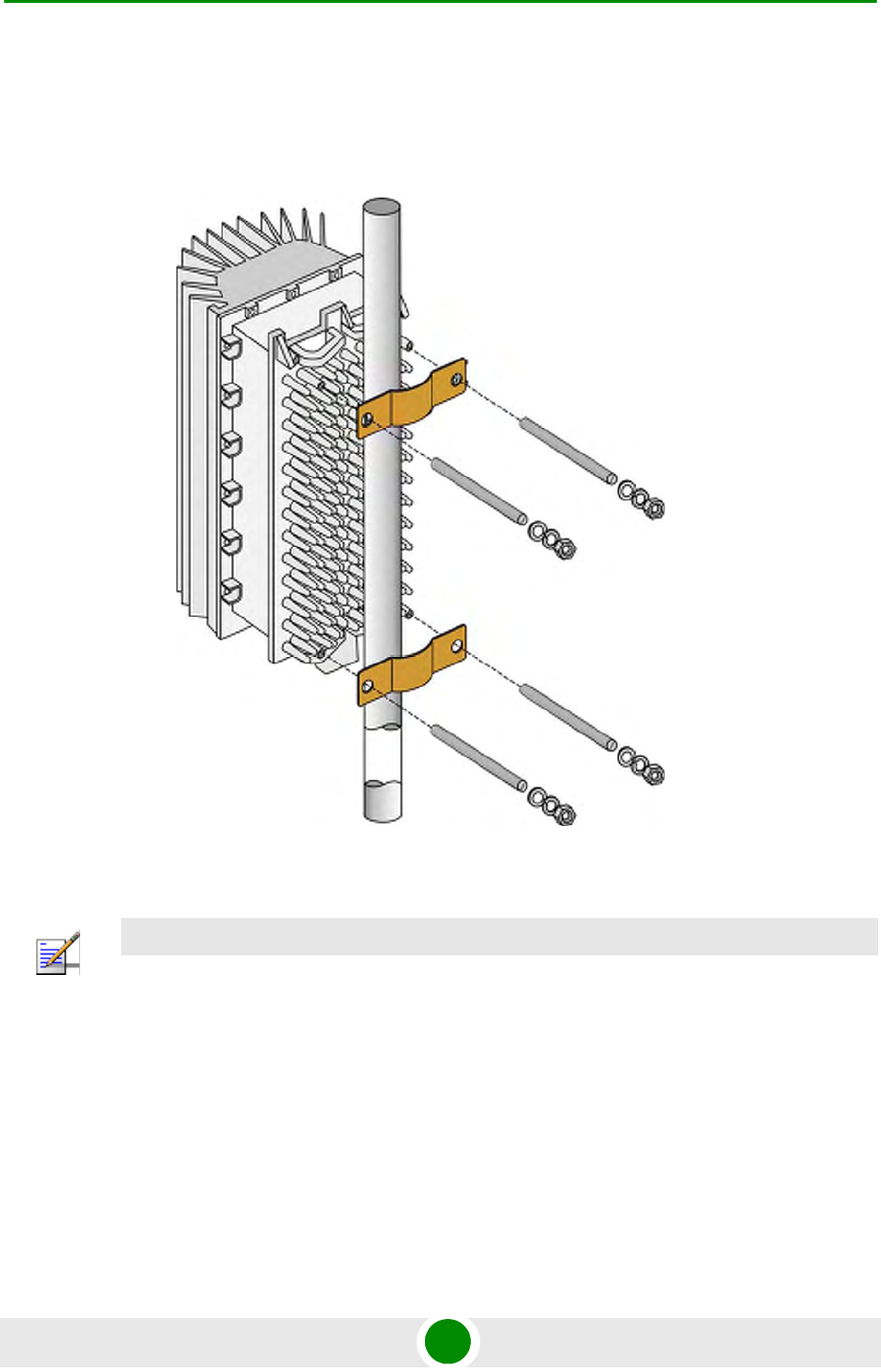
Chapter 2 - Installation Installing the ODU
4Motion 46 System Manual
2.1.3.2.1 Pole Mounting the ODU Using Clamps
Figure 2-1 illustrates the method of mounting a ODU on a pole, using the clamps
and threaded rods.
Figure 2-1: ODU Pole Installation Using Special Clamps
NOTE
There is a groove on one end of the threaded rod. Insert the threaded rods with the grooves
pointing outward, as these grooves enable you to use a screwdriver to fasten the rods to the unit.
I
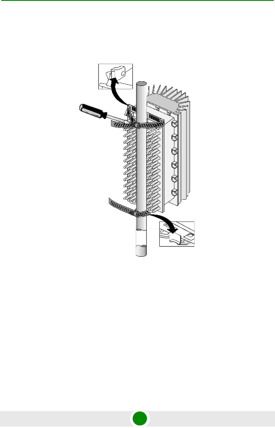
Chapter 2 - Installation Installing the ODU
4Motion 47 System Manual
2.1.3.2.2 Pole Mounting the ODU Using Metal Bands
Figure 2-2 illustrates the method of mounting a ODU on a pole, using metal
bands.
Figure 2-2: ODU Pole Installation Using Metal Band
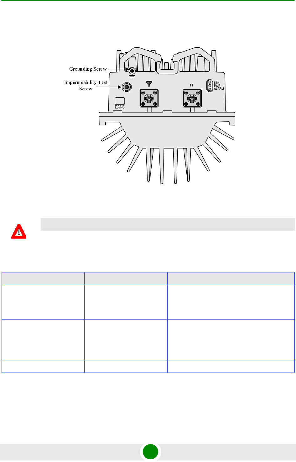
Chapter 2 - Installation Installing the ODU
4Motion 48 System Manual
2.1.3.3 1x1 ODU Connectors and LEDs
Figure 2-3: Bottom Panel of the 1x1 ODU
CAUTION
Do not open the impermeability test screw - you may impair the sealing of the unit against moisture
and humidity.
Table 2-3: 1x1 ODU LEDs
Name Description Functionality
PWR Power indication Off - Power failure
Green - Power to ODU is OK, internal 3.3
VDC power supply is OK.
ALARM AU-ODU communication and
synthesizer status indication
Off - AU-ODU communication is OK,
synthesizer is locked.
Red - AU-ODU communication failure or
synthesizer is not locked
ETH Not Used

Chapter 2 - Installation Installing the ODU
4Motion 49 System Manual
2.1.4 Installing the 4x2 ODU
2.1.4.1 AU-ODU Package Contents
ODU (weight 15.5 kg +/- 1.5 kg)
Carriage for ODU (weight 6 kg)
Four M10X30 screws
Pole Mounting Kit for one ODU: (weight ~6 kg)
»Two M10 clamps for 1.5”-6” poles
»Four M10x265 threaded rods
»Eight M10 nuts
»One M6X12 grounding screw
»Eight M10 spring washers
»Eight M10 flat washers
2.1.4.2 Sun Guard Package Content
4x2 ODU Sun Guard
Four M6X16 screws
Table 2-4: 1x1 ODU Connectors
Name Connector Functionality
IF TNC jack Connection to the AU/ODU Power Feeder
ANT N-Type jack, 50 Ohm Connection to an external antenna
(GND) Grounding screw Connection to ground (earth)
IMPORTANT
The weight of each ODU is 15.5 kg (+/- 1 kg) and the weight of the Pole Mounting
Kit is approximately 6 kg. Be sure to plan the installation accordingly. It is
recommended to use a harness to lift the units.
Install the AU-ODUs using the supplied kit only.

Chapter 2 - Installation Installing the ODU
4Motion 50 System Manual
2.1.4.3 Pole Mounting Kit for Two ODUs Package Content (Optional)
Four M10x265 threaded rods
Eight M10 nuts
One M6X12 grounding screw
Eight M10 spring washers
Eight M10 Flat Washers
Total weight: ~6 kg
2.1.4.4 L-shape Mast Mounting Kit for Two ODUs (Optional)
Two mounting brackets with adapter for L-shape mast 60-100mm
Two mounting brackets for L-shape mast 60-100mm
Eight M12 spring washers
12 M12 flat washers
Four M12 anchoring bolts (rods), SAE1045 L=140
12 M12 hex nuts x 1.75 DIN 934
Total weight: ~18 kg
2.1.4.5 Pole Mounting Kit for Three ODUs (Optional)
Six mounting brackets for 6"-8" or 10”-14” poles
Two mounting brackets for 6"-8" or 10”-14” poles
Eight M12 anchoring bolts, SAE1045 L=140 (for 14" pole use L=160)
16 M12 spring washers
24 M12 flat washers
16 hex nuts M12 X 1.75 DIN 934

Chapter 2 - Installation Installing the ODU
4Motion 51 System Manual
Eight hex nuts M12 X 1.75 DIN 439
Total weight: 60 kg
2.1.4.6 Additional Installation Requirements
The following items are also required to install the AU-ODU:
four IF cables with two TNC connectors* on either side (see Section 2.1.3 for
details on IF cable types and length).
Antenna(s)* and four RF cables* for connecting the antenna(s) to the ODU
Grounding cable with an appropriate termination
Installation tools and materials, including appropriate means (e.g. a 1.5" to 6"
pole, a harness) for installing the ODU and antenna
2.1.4.7 4x2 ODU Installation Guidelines
The ODU can be mounted on a 1.5" to 6" pole depending on the pole
construction.
To install two ODUs it is recommended to use the optional Mounting Kit for
two ODUs available from Alvarion. The installation of more than two ODUs can
be carried out in one of the following ways:
»Position the third ODU directly beneath one of the two ODUs, with a
distance of 30 cm between the top and bottom carriage to allow easy
routing of the cables.
»Position the third ODU at an angle below the two ODUs. No minimum
distance is required.
IMPORTANT
When planning the installation, be sure to consider the weight of the ODUs and
mounting kits. It is recommended to use a harness to lift the units.
Install the ODUs using the supplied kit only.
NOTE
Items marked with an asterisk (*) are available from Alvarion.
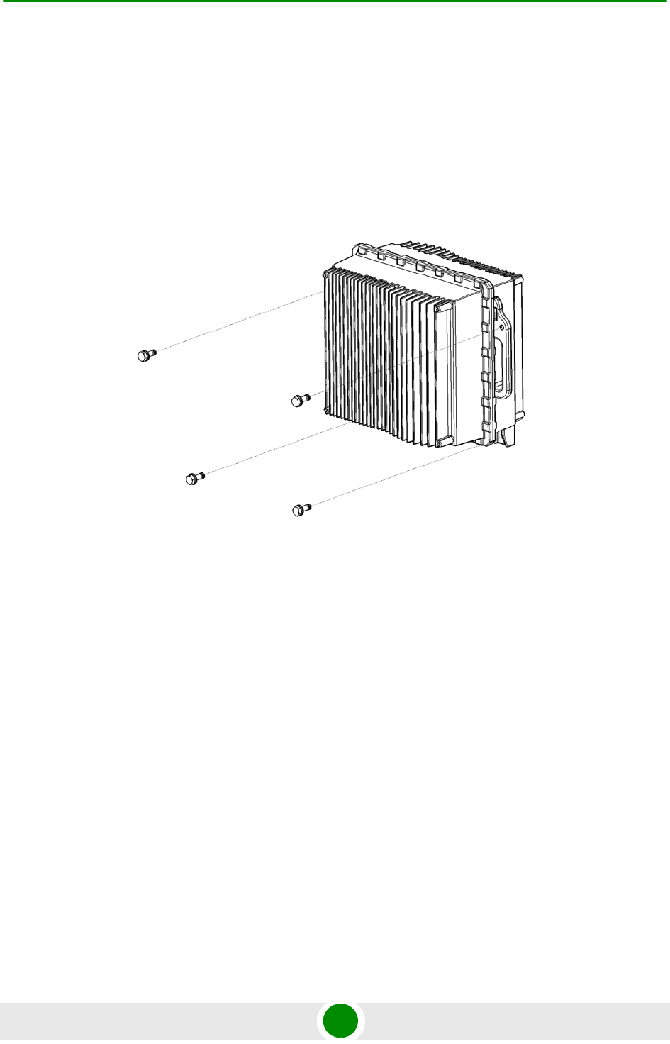
Chapter 2 - Installation Installing the ODU
4Motion 52 System Manual
Sun guard requirements: For 3.5 GHz 4x2 ODU, installing a Sun guard is
mandatory.
2.1.4.8 Pole Mounting One ODU
1Open the packaging and remove the ODU and screws.
2Insert the four M10X30 screws into the designated holes (Figure 2-4).
3Position the carriage on the pole at the desired location.
4Thread the four M10x265 threaded rods through the carriage and the rear
clamps (Figure 2-5).
5 Tighten on both sides using the supplied washers, spring washers and nuts.
Figure 2-4: Preparing the 4x2 ODU for Installation
ODU
M10x30 screws
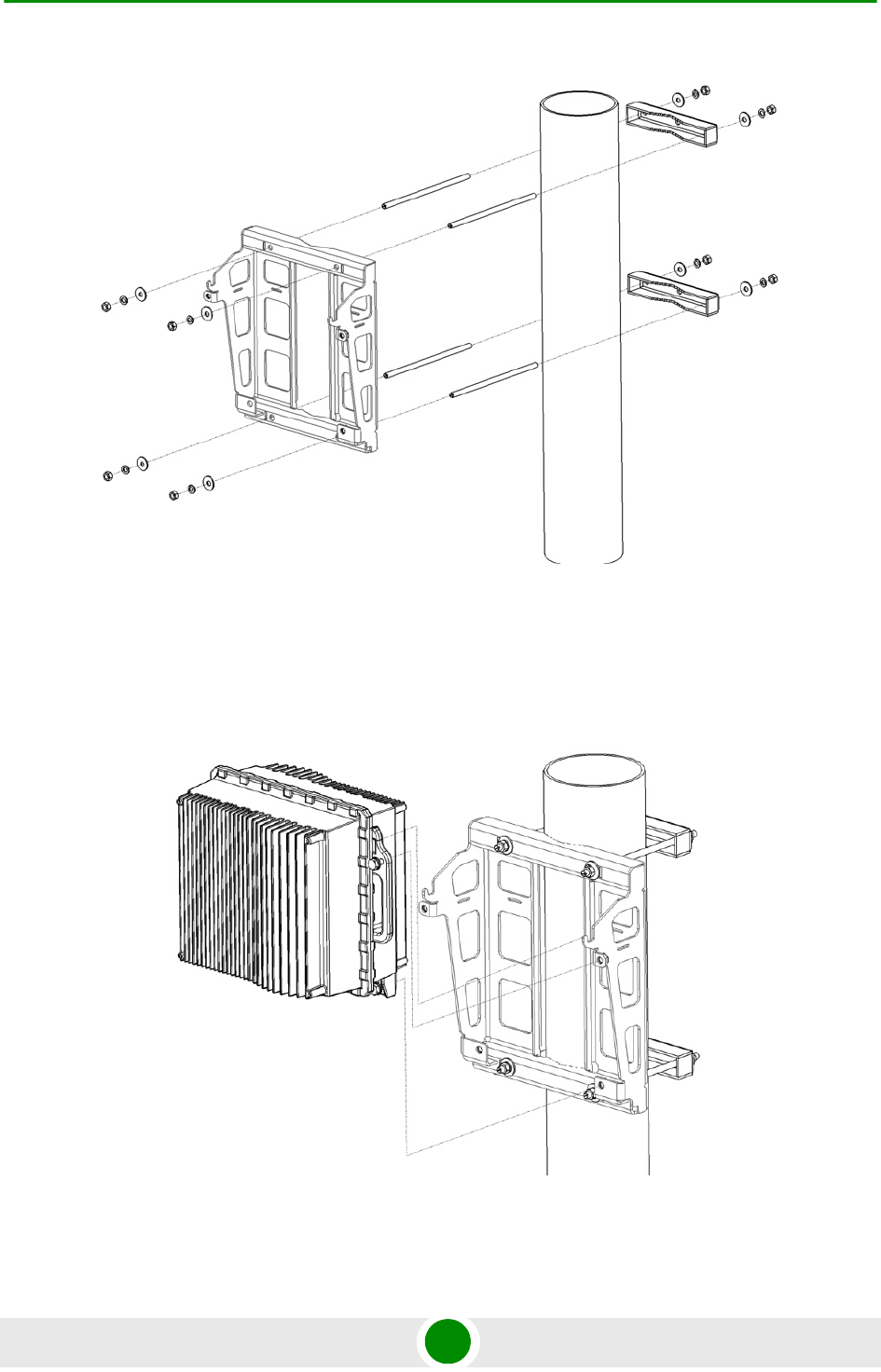
Chapter 2 - Installation Installing the ODU
4Motion 53 System Manual
6Hang the ODU on the carriage and tighten the four M10x30 screws (Figure 2-6
and Figure 2-7).
Figure 2-5: Mounting the Single 4x2 ODU Carriage on a Pole
Figure 2-6: Mounting the 4x2 ODU
M10x265 Threaded Rods
M10 Clamps
M10 nuts, washers, spring washers
Carriage for 4x2 ODU
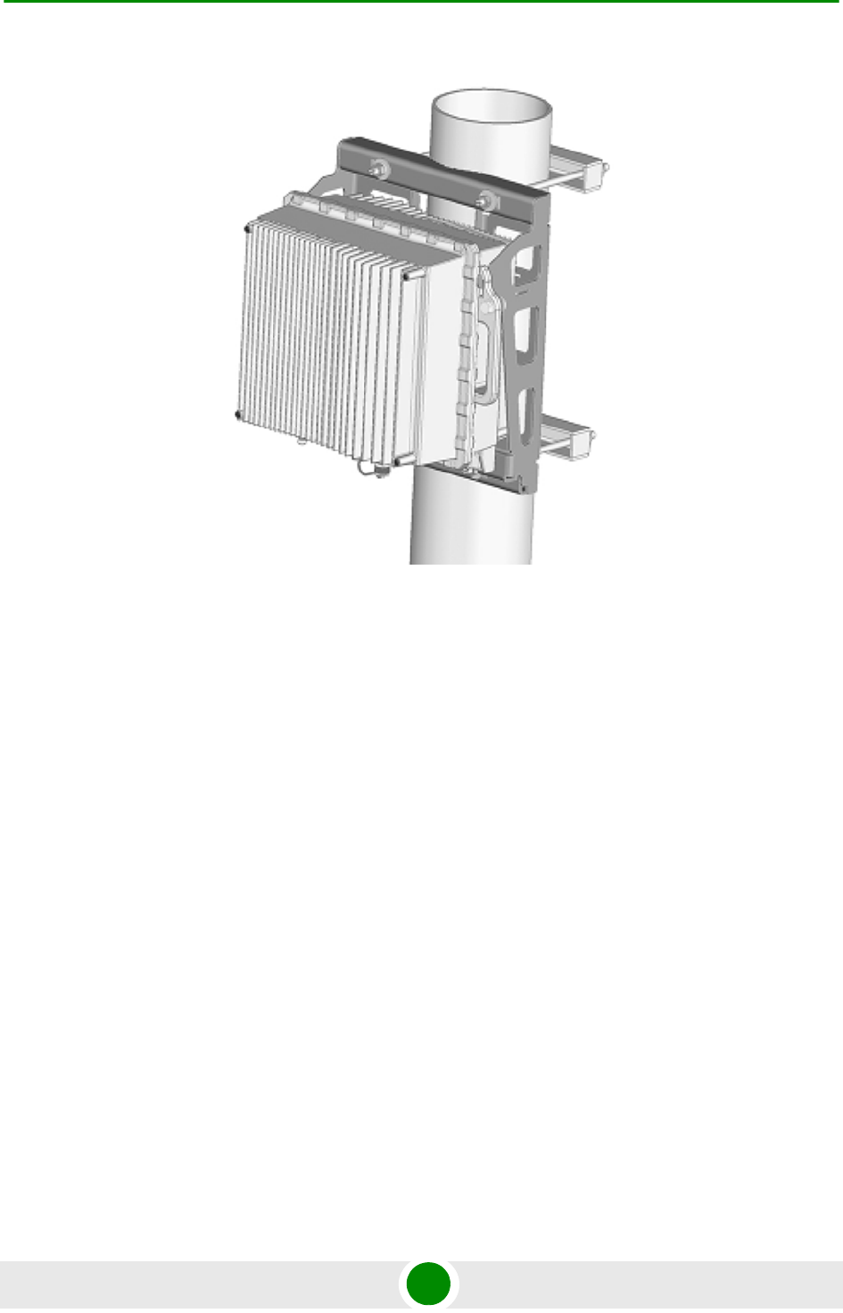
Chapter 2 - Installation Installing the ODU
4Motion 54 System Manual
2.1.4.9 Pole Mounting Two ODUs
1Prepare the two ODUs for installation as shown in Figure 2-4.
2Position both carriages at the desired location on the pole.
3Thread the 4 M10x265 threaded rods through one carriage and tighten using
the supplied washers, spring washers and nuts. Lean the carriage vertically on
the pole and thread the rods through the second carriage (Figure 2-8).
4Tighten using the washers, spring washers and nuts.
Figure 2-7: 4x2 ODU Mounted on Pole
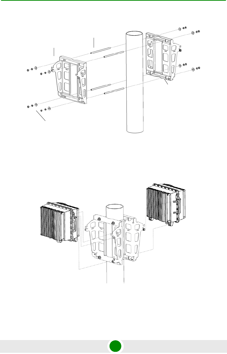
Chapter 2 - Installation Installing the ODU
4Motion 55 System Manual
5Hang the ODUs on the carriages and tighten the M10x30 screws (Figure 2-9
and Figure 2-10).
Figure 2-8: Mounting Two Carriages on the Pole
Figure 2-9: Mounting the two ODUs
Carriage for 4x2 ODU
M10 nuts, washers, spring washers
Carriage for ODU-HP
M10x265 Threaded Rods
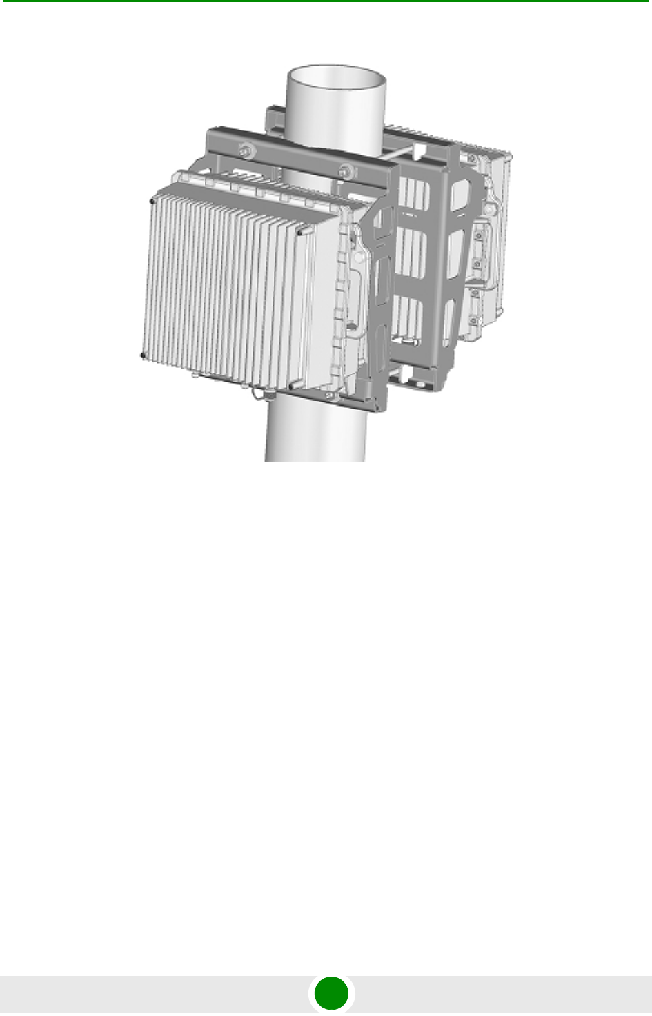
Chapter 2 - Installation Installing the ODU
4Motion 56 System Manual
2.1.4.10 Pole Mounting Three 4x2 ODUs
1Prepare the three ODUs for installation as shown in Figure 2-4.
2Assemble the mounting brackets at the desired location on the pole as shown
in Figure 2-11.
Figure 2-10: Two ODUs Mounted on the Pole
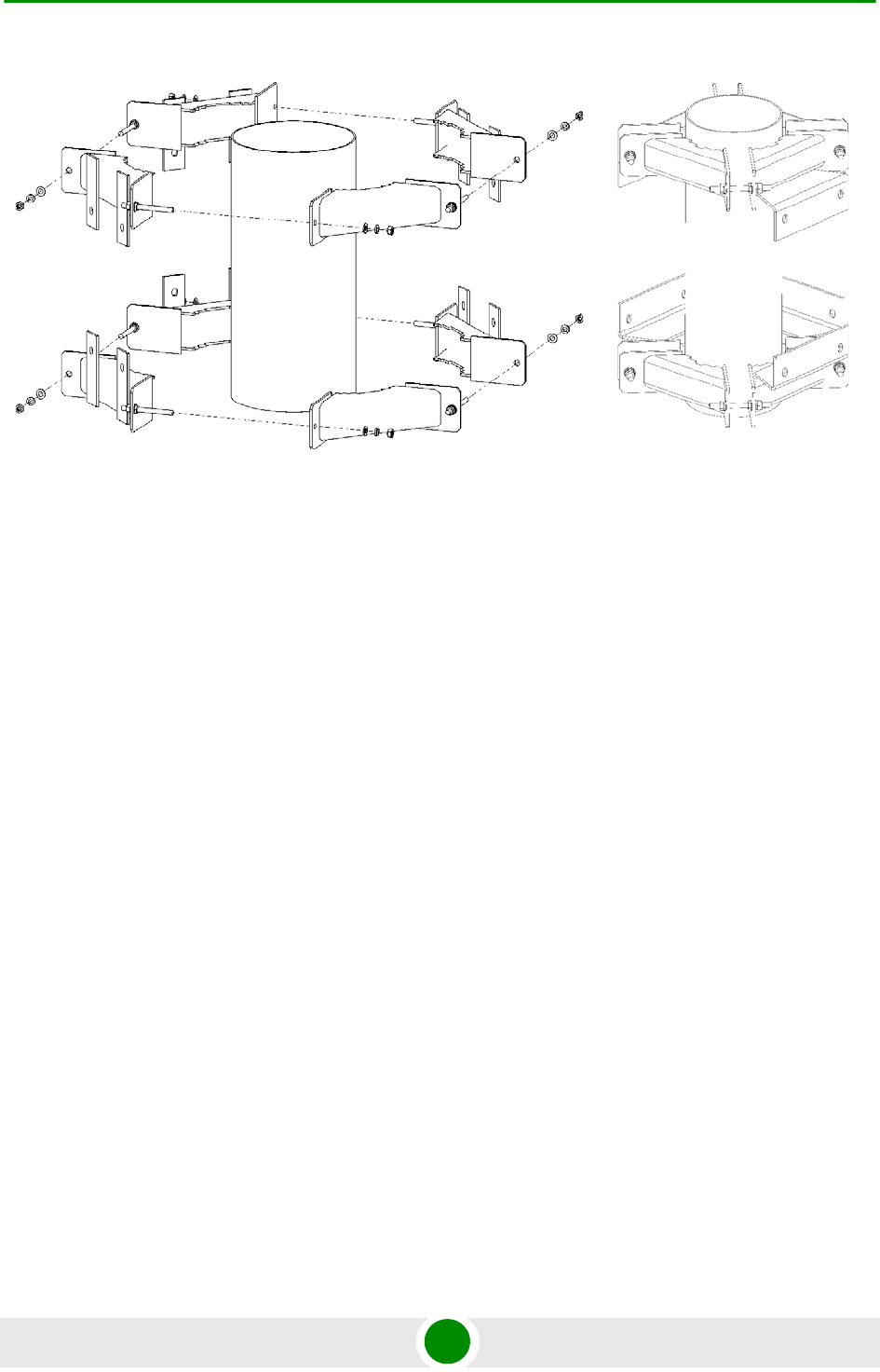
Chapter 2 - Installation Installing the ODU
4Motion 57 System Manual
3Attach the carriage to the bracket and tighten using the supplied washers,
spring washers and nuts (Figure 2-12). Repeat for the other carriages.
4Hang the ODUs on the carriages and tighten the M10x30 screws (Figure 2-9
and Figure 2-14).
Figure 2-11: Assembling the Mounting Brackets
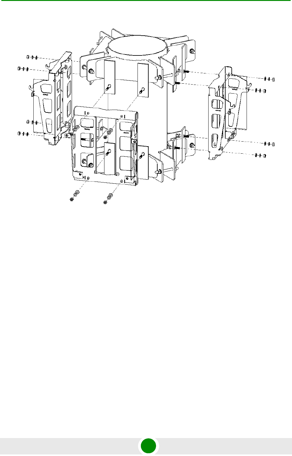
Chapter 2 - Installation Installing the ODU
4Motion 58 System Manual
Figure 2-12: Mounting Three Carriages on the Pole
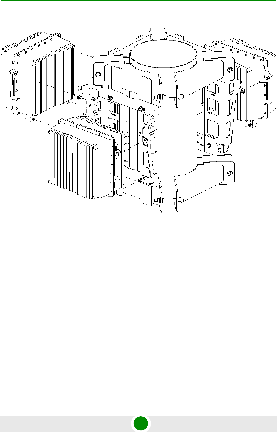
Chapter 2 - Installation Installing the ODU
4Motion 59 System Manual
Figure 2-13: Mounting the Three 4x2 ODUs
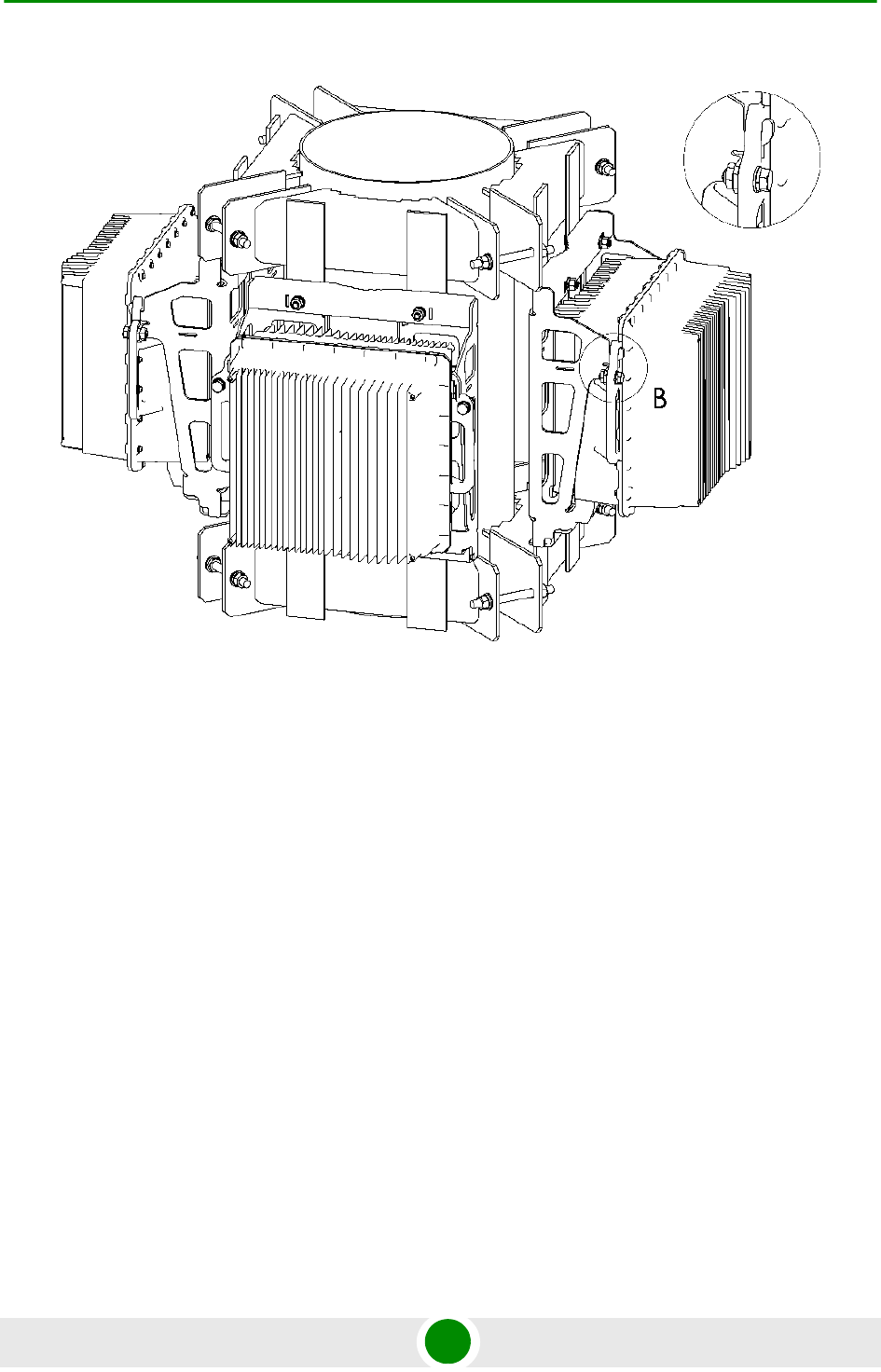
Chapter 2 - Installation Installing the ODU
4Motion 60 System Manual
2.1.4.11 L-shape Mast Mounting - Two 4x2 ODUs
1Prepare the two ODUs for installation as shown in Figure 2-4.
2Assemble the mounting brackets at the desired location on the L-shape mast
as shown in Figure 2-15. Tighten using the supplied washers, spring washers
and nuts.
Figure 2-14: Three 4x2 ODUs Mounted on the Pole
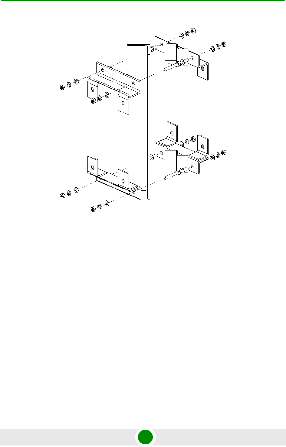
Chapter 2 - Installation Installing the ODU
4Motion 61 System Manual
3Thread the four M10x265 threaded rods through one carriage and bracket,
and tighten using the supplied washers, spring washers and nuts. Repeat for
the second carriage (Figure 2-16).
Figure 2-15: Assembling the Mounting Brackets
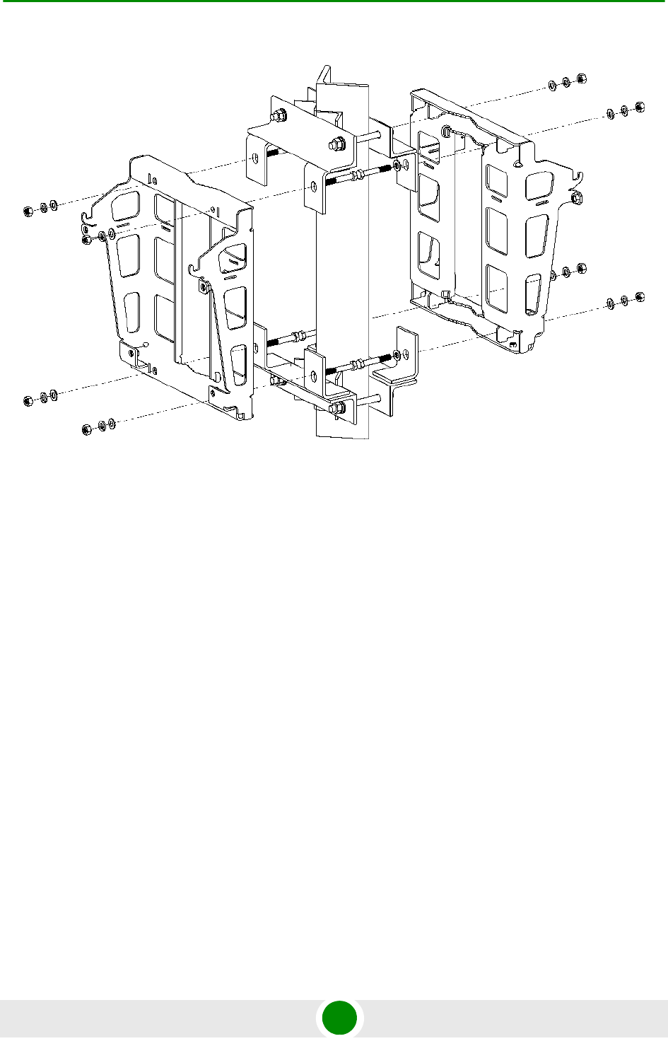
Chapter 2 - Installation Installing the ODU
4Motion 62 System Manual
4Tighten using the washers, spring washers and nuts.
5Hang the ODUs on the carriages and tighten the M10x30 screws (Figure 2-17
and Figure 2-18).
Figure 2-16: Mounting the Carriages on the L-shape Mast
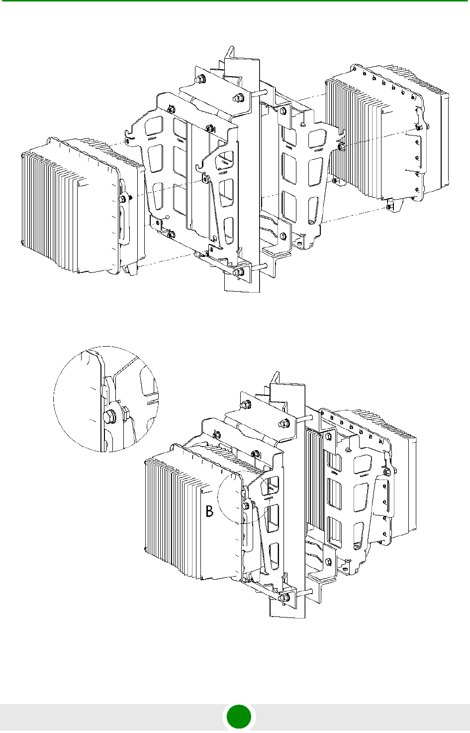
Chapter 2 - Installation Installing the ODU
4Motion 63 System Manual
Figure 2-17: Mounting the ODUs on the Carriages
Figure 2-18: Two 4x2 ODUs Mounted on the L-shape Mast
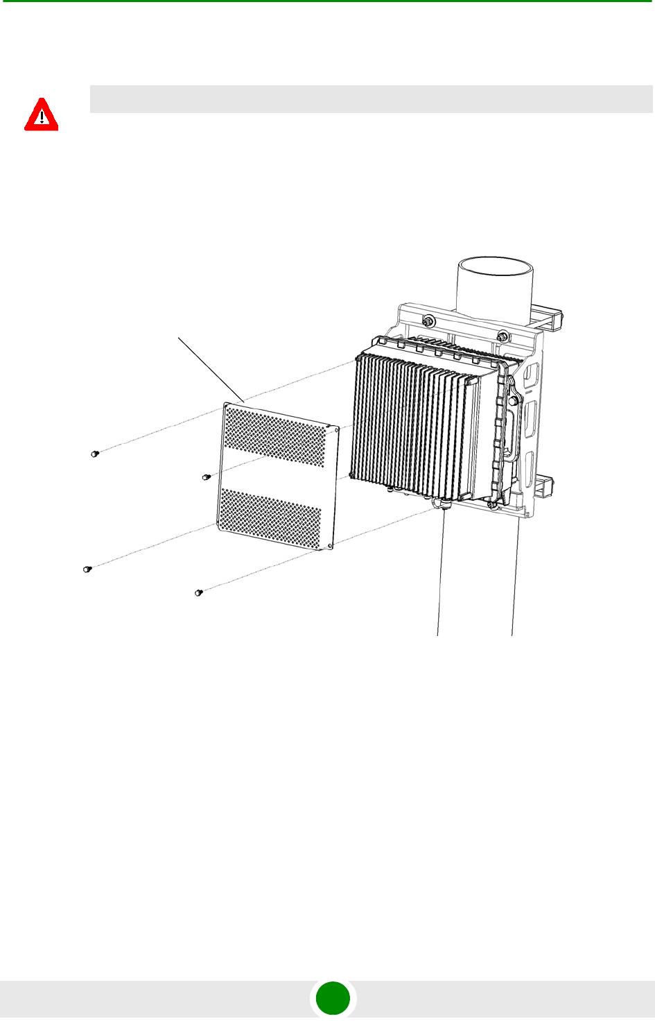
Chapter 2 - Installation Installing the ODU
4Motion 64 System Manual
2.1.4.12 Mounting the Sun Guard
1Attach the Sun Guard to the front of the ODU using the four M6x16 screws
supplied with the Sun Guard.
CAUTION
To avoid damage to the Sun Guard, assemble it after the ODUs are mounted on the pole.
Figure 2-19: Attaching the Sun Guard to the 4x2 ODU
Sun Guard
M6x16 screws
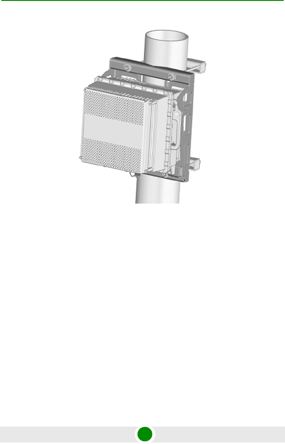
Chapter 2 - Installation Installing the ODU
4Motion 65 System Manual
Figure 2-20: 4x2 ODU with Sun Guard
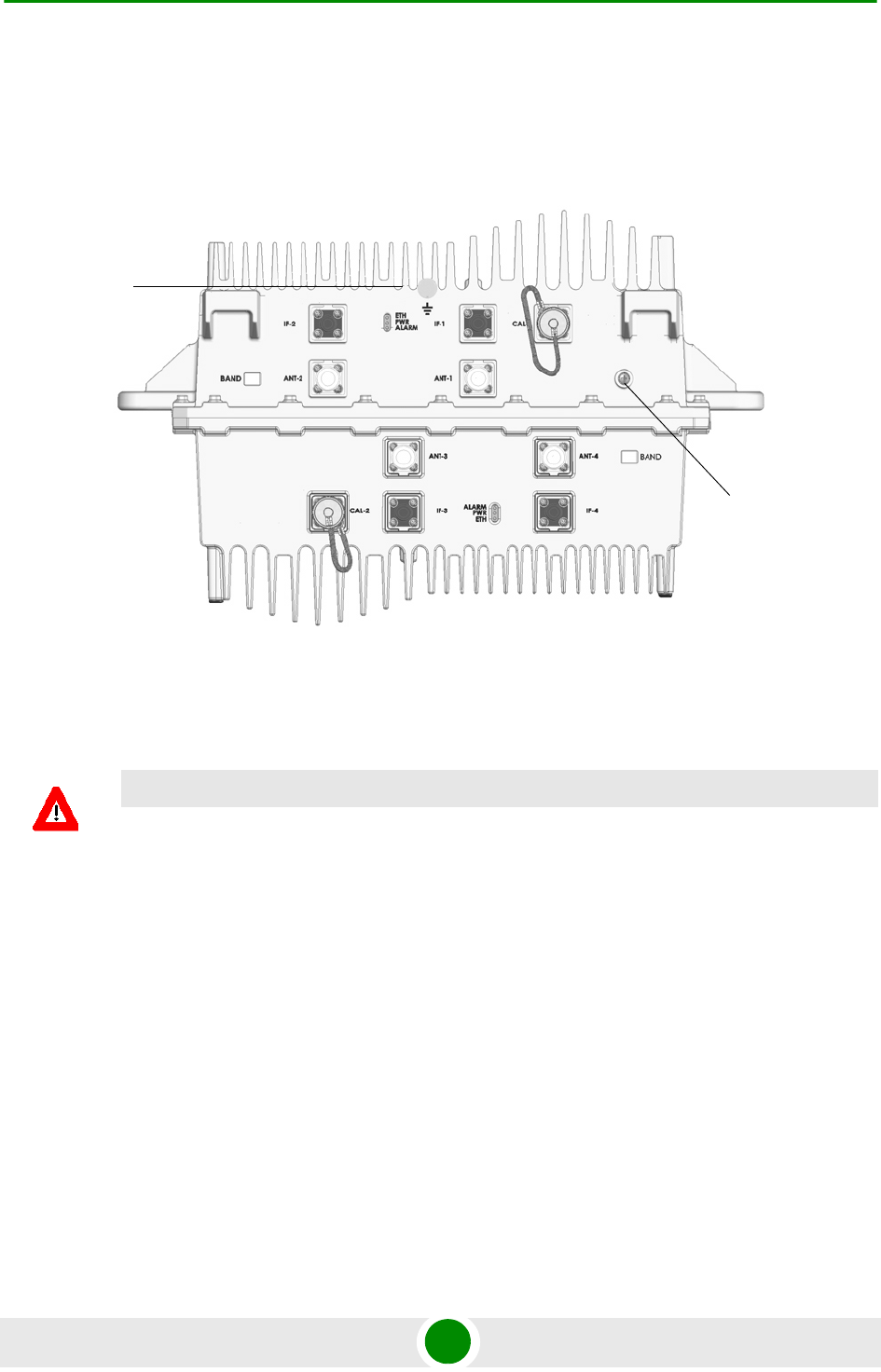
Chapter 2 - Installation Installing the ODU
4Motion 66 System Manual
2.1.4.13 4x2 ODU Connectors and LEDs
Figure 2-21: Bottom Panel of 4x2 ODU
CAUTION
Do not open the impermeability test screw - you may impair the sealing of the unit against moisture
and humidity.
Grounding Screw
Impermeability
Test Screw
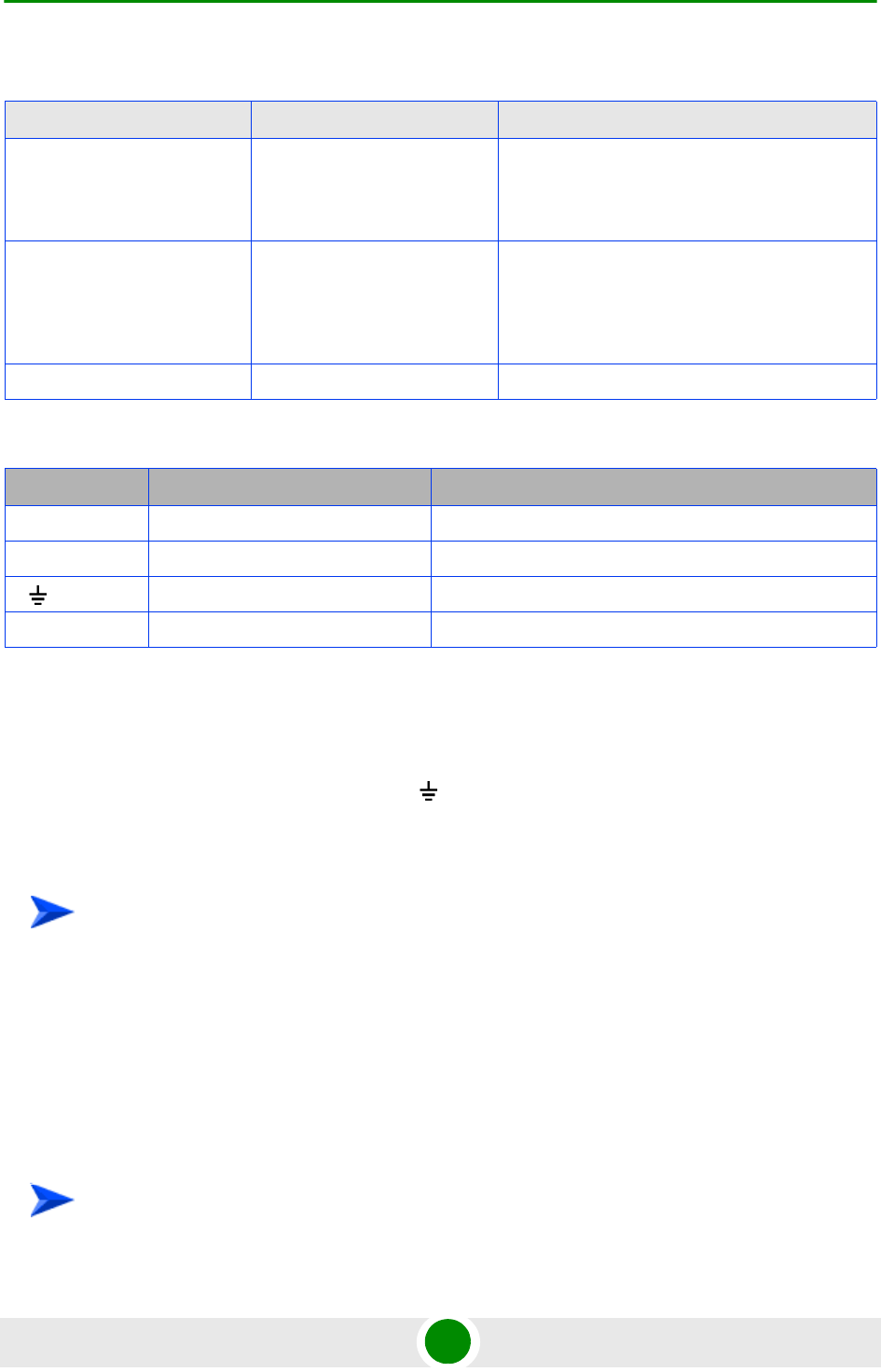
Chapter 2 - Installation Installing the ODU
4Motion 67 System Manual
2.1.5 Connecting the Cables
2.1.5.1 Connecting the Grounding Cable
The Grounding screw (marked ) is located on the bottom panel of the outdoor
unit.
1Connect one end of a grounding cable to the grounding screw and tighten the
grounding screw firmly.
2Connect the other end of the grounding cable to a good ground (earth)
connection.
2.1.5.2 Connecting the Antenna Cable
Table 2-5: 4x1 ODU LEDs
Name Description Functionality
PWR Power indication Off - Power failure
Green - Power to ODU is OK, internal 3.3
VDC power supply is OK.
ALARM AU-ODU communication and
synthesizer status indication
Off - AU-ODU communication is OK,
synthesizer is locked.
Red - AU-ODU communication failure or
synthesizer is not locked
ETH Wireless Link Traffic Green when there is traffic on the wireless link
Table 2-6: 4x1 ODU Connectors
Name Connector Functionality
IF-1 to IF-4 4 x TNC jack Connection to the AU/ODU Power Feeder
ANT-1 to ANT-4 4 x N-Type jack, 50 Ohm Connection to an external antenna
(GND) Grounding screw Connection to ground (earth)
CAL-1, CAL-1 Not used in current release
To connect the grounding cable:
To connect the RF cable:

Chapter 2 - Installation Installing the ODU
4Motion 68 System Manual
1Connect one end of the coaxial RF cable to the RF (ANT) connector located on
the bottom panel of the unit.
2Connect the other end of the RF cable to the antenna.
3The RF connectors should be properly sealed to protect against rain and
moisture.
2.1.5.3 Connecting the IF Cable
1Connect one end of the coaxial IF cable to the IF connector located on the
bottom panel of the unit.
2Verify that the length of the IF cable is sufficient to reach the AU/Power
Feeder. See IF cable length limitation in Section 2.1.2.
3The IF cable connector should be properly sealed to protect against rain and
moisture.
4Route the cable to the location selected for the indoor equipment.
To connect the IF cable:

Chapter 2 - Installation Installing the Antennas
4Motion 69 System Manual
2.2 Installing the Antennas
This section provides general guidelines on installation of antennas and necessary
accessories provided by Alvarion.
2.2.1 Guidelines for Positioning the Antennas
This section provides key guidelines for selecting the optimal installation locations
for the antennas.
Select the optimal locations for the equipment using the following guidelines:
The antennas are pole or wall mounted. Their location should enable easy
access to the unit for installation and testing.
The higher the placement of the antenna, the better the achievable link
quality.
The antenna should be installed so as to provide coverage to the intended
service area.
The antenna should be installed as close as possible to the ODU.
2.2.2 Antenna Installation Requirements
The following equipment is required to complete installation of the antennas,
including all equipment required for controlling the electronic downtilt of the
antennas (RET):
CAUTION
ONLY experienced installation professionals who are familiar with local building and safety codes
and, wherever applicable, are licensed by the appropriate government regulatory authorities should
install outdoor units and antennas.
Failure to do so may void the BreezeMAX product warranty and may expose the end user or
Service Provider to legal and financial liabilities. Alvarion and its resellers or distributors are not
liable for injury, damage or regulation violations associated with the installation of Outdoor Units or
antennas.
NOTE
The recommended minimum distance between any two antennas in neighboring sectors is 0.5
meters.

Chapter 2 - Installation Installing the Antennas
4Motion 70 System Manual
Antennas, including mounting kit (fixed and adjustable downtilt).
Remote Cable Outdoor Termination Unit (3 Way AISG Breakout Box): One for
up to 3 antennas, 2 for 4 to 6 antennas.
Long AISG Remote Cable (available in length of 60 or 80 meter).
Remote Cable Termination Panel.
Short AISG Remote Cables (available in length of 2, 3 or 5 meter according to
the distance of the Remote Cable Outdoor Termination Unit from the
antennas): One for each antenna. An additional cable is required if two Remote
Cable Outdoor Termination Units are used.
Remote Downtilt Control Kit.
RF cables for connecting the antenna to the ODU(s).
2.2.3 Recommended Installation Procedure
2.2.3.1 Pre-Installation
1Connect the AISG Antenna Controller to each antenna to verify that it
functions properly. Check the address of each antenna and note it together
with its planned location (azymuth) for future reference. Note that an XX
antenna (4 ports antenna) has two bands, each with its own RET adjustment.
For details on using the AISG Antenna Controller refer to the documentation
supplied with it. Return the electronic downtilt to 0 degrees to ensure that the
indicator will not be damaged during installation.
2Prepare the short AISG Remote Cables and connect them to the Remote Cable
Outdoor Termination Unit(s). If two Remote Cable Outdoor Termination Units
should be installed, prepare and connect also the cable interconnecting the
two units. Refer to the instruction supplied with the unit. Connect the
antennas and use the AISG Antenna Controller to verify proper operation.
Disconnect the antennas and Controller (and interconnecting cable if used).
2.2.3.2 Installation
1Install the Remote Cable Termination Panel in a 19” rack. Its placement
should enable easy connection of the AISG Antenna Controller.

Chapter 2 - Installation Installing the Antennas
4Motion 71 System Manual
2Install the antennas according to the planned azymuth. It is recommended to
use the Adjustable Downtilt Kit and set it at 0 degrees downtilt. Refer to the
installation instructions supplied with the antennas.
3Install the Remote Cable Outdoor Termination Unit(s) according to the
instructions supplied with the unit. The placement of the unit(s) should enable
connection of all the AISG Remote Cables to the antennas. Connect all the
cables to the antennas. If needed, connect the two units using the
pre-prepared cable.
4Connect the long AISG Remote Cable to the Remote Cable Outdoor
Termination Unit and route it to the location of the Remote Cable Termination
Panel. Connect it to the Panel according to the instructions supplied with the
Panel.
5Connect the AISG Antenna Controller to the Remote Cable Termination Panel
and set to downtilt of each antenna to the desired angle. For recommendation
on typical downtilt required in various scenarios refer to “Antenna Down-Tilt
Guidelines” on page 842.

Chapter 2 - Installation Installing the Base Transceiver Station (BTS) Equipment
4Motion 72 System Manual
2.3 Installing the Base Transceiver Station
(BTS) Equipment
2.3.1 BTS Installation Requirements
2.3.1.1 Packing List
BTS Chassis:
»Base Transceiver Station Chassis
»AVU Air Ventilation Unit (installed)
»Cables Tray kit
PIU (1 or 2 per chassis) High-Power Interface Unit(s). A suitable DC power
cable is supplied with each PIU.
PSU (up to 4 per chassis) Power Supply Unit(s)
NPU Network Processing Unit and Monitor cable
AU-4CH Access Unit Indoor Unit(s) as required for specific configuration
2.3.1.2 Additional Installation Requirements
The following items are also required to install the BTS:
Ethernet cable (straight) for connecting the NPU to a Hub/Switch.
A grounding cable with appropriate terminations for connecting the chassis to
the rack or another ground (earth) connection.
For installation in a 21" ETSI rack: Two 21" ETSI rack adapters
A portable PC for configuring parameters using the Monitor cable (supplied
with the NPU)
NOTE
The maximum length of the Ethernet cable is 100m when operating at 100 Mbps and 70m when
operating at 1 Gbps.
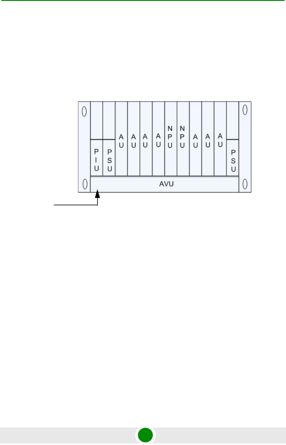
Chapter 2 - Installation Installing the Base Transceiver Station (BTS) Equipment
4Motion 73 System Manual
Other installation tools and materials
2.3.2 BTS Chassis Slot Assignments
The BTS chassis comprises 6 3U high slots and 9 6U high slots, as shown in
Figure 2-22.
The Cable Tray (the installation kit is supplied with the chassis) should be
installed on the top of the chassis front to enable convenient routing of cables
connecting to power source(s), outdoor unit(s) and other equipment.
To enable power source and/or Power Interface Unit 1+1 redundancy, two PIU
modules can be installed in the designated slots. If a single PIU module is used, it
can be inserted into either one of the two designated slots.
The number of installed PSU modules depends on the specific configuration
(number of AUs) and NPU redundancy scheme (refer to Table 2-10). If less than 4
PSU modules are used, they can be installed in any of the designated slots.
The NPU should be installed in slot number 5 (slot numbers are marked on the
Cable Guide). Slot 6 is reserved for a future redundant NPU.
Slots 1-4 and 7-9 can hold up to seven AU modules (only six AUs can be active).
Unused slots should remain covered until required.
Figure 2-22: BTS Chassis Slot Assignments
Air
Ventillation
Unit

Chapter 2 - Installation Installing the Base Transceiver Station (BTS) Equipment
4Motion 74 System Manual
2.3.3 Power Requirements
2.3.3.1 General Power Requirements
Use the following table to calculate worst-case power source requirements for the
BTS equipment:
Table 2-7: Power Requirements, BTS Equipment
Unit Details
Power Source -40.5 to -60 VDC
PIU Power Consumption: 35W maximum (active PIU)
Maximum Supplied Current: 58 A
PSU 300W max output power
Efficiency: 80% minimum
NPU 68W maximum, excluding GPS Receiver (6W maximum)
AU-4CH 74W maximum
1x1 ODU-2.x GHz Tx (DL): 89W maximum
Rx (UL): 15W maximum
1x1 ODU-3.5 GHz Tx (DL): 90W maximum
Rx (UL): 20W maximum
4x2 ODU 2.x GHz
(constructed of two independent
2x1 units)
For each 2x1 unit:
Tx (DL): 142W maximum
Rx (UL): 35W maximum
4x2 ODU 3.5 GHz
(constructed of two independent
2x1 units)
For each 2x1 unit:
Tx (DL): 108W maximum
Rx (UL): 12W maximu
AVU 40W maximum, 23W typical
Outdoor GPS Receiver 6W maximum
NOTE
The PSU(s) do not supply power to the ODUs that are powered directly from the PIU via the
backplane and the AU cards. The PIU can support up to a maximum of 20 1x1 ODUs. Additional
ODUs should be powered from ODU Power Feeders (not applicable for current release).

Chapter 2 - Installation Installing the Base Transceiver Station (BTS) Equipment
4Motion 75 System Manual
2.3.3.2 Power Calculation Example
Configuration: A 2.x GHz BTS with 3 AU cards and 4 1x1 ODUs connected to each
AU. Uplink-Downlink split (allocation ratio) of 12-34.
Maximum power consumption that should be supplied by PSUs:
NPU: 68W
3 AUs: 3*74=222W
AVU: 40W
GPS Receiver: 6w
Total maximum power supplied by PSUs: 336W
Total maximum power required excluding ODUs: 336/0.8 (PSUs Efficiency) + 35
(PIU) = 455W
When calculating the power requirements associated with the ODUs, we should
distinguish between the peak power consumption (maximum current during Tx)
and the average power consumption (taking into account Tx/Rx split ratio) that
affect the requirements from a backup power source.
For a 2.x GHz system, the peak power consumption of 12 ODUs under worst
conditions is 12*89 = 1068W. Thus, the maximum peak power of the system is
455 + 1068 = 1523W (37.6A @ -40.5 VDC).
The maximum average power consumption of each ODU, assuming UL-DL
(Rx/Tx) ratio of 12-34 is (15*12+89*34)/46 = 70W. Thus, the maximum average
power required for the whole system is 455 + 70*12 = 1295W (32A @ -40.5 VDC).
2.3.3.3 Power Feeders Requirements
According to required configuration, each AU can be connected to one, two, or
four 1x1 ODUs. It may also be connected to either one or two 2x1 ODUs: A 4x2
ODU is treated and functions as two independent 2x1 ODUs. The two 2x1 ODUs
that form a 4x2 ODU are powered via the TX/Rx Ports (Ports 1 and 3).
Once an ODU Feeder is installed, all 4 channels should be used.
Power Feeders are required in the following configurations:
Table 2-8: Power Feeder Requirements
Configuration Number of Power Feeders
5 AUs, each AU connected to four 1x1 ODUs 1

Chapter 2 - Installation Installing the Base Transceiver Station (BTS) Equipment
4Motion 76 System Manual
2.3.4 HOT SWAP Support
The NPU, AU, and PIU modules includes a blue HOT SWAP LED and a
micro-switch in the injector/ejector handle to support hot-swap control. After
releasing the ejector's button, the HOT SWAP LED should turn on, indicating that
power to/from the back-panel is disconnected and the module can be removed
safely.
2.3.5 Power Interface Unit (PIU)
The single Euro PIU module serves as the interface between the BTS site's DC
power source and the BTS Chassis Power Supply Units and external ODUs, which
receive power via the IDUs.
The PIU filters and stabilizes the BTS input power and protects the system from
power problems such as over voltage, surge pulses, reverse polarity connection
and short circuits. It also filters high frequency interference (radiated emissions)
and low frequency interference (conducted emissions) to the external power
source. Each BTS chassis contains two slots for an optional 1+1 PIU redundancy.
One PIU is sufficient to support a fully populated chassis. Two PIU modules
provide redundant power feeding (two input sources) while avoiding current flow
between the two input sources.
6 AUs, each AU connected to four 1x1 ODUs 2
6 AUs, each AU connected to two 2x1 2.5 GHz ODUs 1
Table 2-8: Power Feeder Requirements
Configuration Number of Power Feeders
Chapter 2 - Installation Installing the Base Transceiver Station (BTS) Equipment
4Motion 77 System Manual
Figure 2-23: PIU Module Front Panel
CAUTION
When replacing a PIU, disconnect power from the PIU module before inserting/ejecting it to/from
the chassis. After disconnecting from power, disconnect the power cable to avoid irreversible
damage due to potential excessively high transient current. Connect power to the PIU only after it is
fully inserted into the chassis.
Table 2-9: PIU LEDs
PWR and
MASTER/ACT LEDs PIU Status
PWR MASTER/
ACT
Off Off Chassis is not connected to power
Red Off Power input is out of range or PIU card is damaged. Chassis is powered by the
redundant PIU

Chapter 2 - Installation Installing the Base Transceiver Station (BTS) Equipment
4Motion 78 System Manual
2.3.5.1 Preparing a Power Cable for the PIU
A 2.5m DC power cable is supplied with each chassis. Additional DC cables can
be ordered from Alvarion. If necessary, use the following instruction to prepare a
DC cable.
1For a cable length up to 2.5m use a cable with 4 x 10AWG (or thicker) wires for
the power plus and an additional 10AWG (or thicker) ground wire. For a longer
cable (up to 10m), use a cable with 4 x 8AWG (or thicker) wires for the power
plus and an additional 10AWG (or thicker) ground wire.
2The matching power connector to be used is D-SUB 5W5S Female with power
pins 40A.
3Connect the cable to the power connector as follows:
»Pin 1 (RTN): Red (10/8 AWG min wire)
»Pin 2 (-48V): Black (10/8 AWG min wire)
»Pin 3 ( ): Ground (shield), Green/Yellow (10AWG min wire)
»Pin 4 (-48V): Black (10/8 AWG min wire)
»Pin 5 (RTN): Red (10/8 AWG min wire)
4Attach suitable terminal rings to the side that connects to the power source.
Red Green Power input is out of range or PIU card is damaged. Chassis is powered by the PIU
Green Off Power to PIU is OK. PIU is in redundant mode and the chassis is powered from the
other PIU
Green Green Power to PIU is OK. The chassis is powered from the PIU.
HOT SWAP LED Off: Power from the module to the chassis is not disconnected, the PIU is not ready for
removal
Blue: Power from the module to the chassis can be disconnected and the PIU can be
safely removed
To prepare the power cable:
Table 2-9: PIU LEDs
PWR and
MASTER/ACT LEDs PIU Status
Chapter 2 - Installation Installing the Base Transceiver Station (BTS) Equipment
4Motion 79 System Manual
2.3.6 Power Supply Unit (PSU)
The single Euro PSU module is a 48 VDC power supply unit. Each BTS chassis
can contain up to four PSU modules providing N+1 redundancy configurations.
The following table displays the number of PSU modules (excluding redundant
units) required for various BTS configurations:
CAUTION
It is strongly recommended to always use the power cables available from Alvarion.
Due to the high current that should be supported by the cable, good workmanship is esstential in
preparing it.
Table 2-10: PSU Requirements, Configurations with one NPU (excluding PSU redundancy)
Number of AUs Minimum Required Number of PSUs
1 - 4 2
5 - 6 3
NOTE
The PSU(s) do not supply power to the ODUs. ODUsare powered directly from the power source
via the PIU and the back plane.
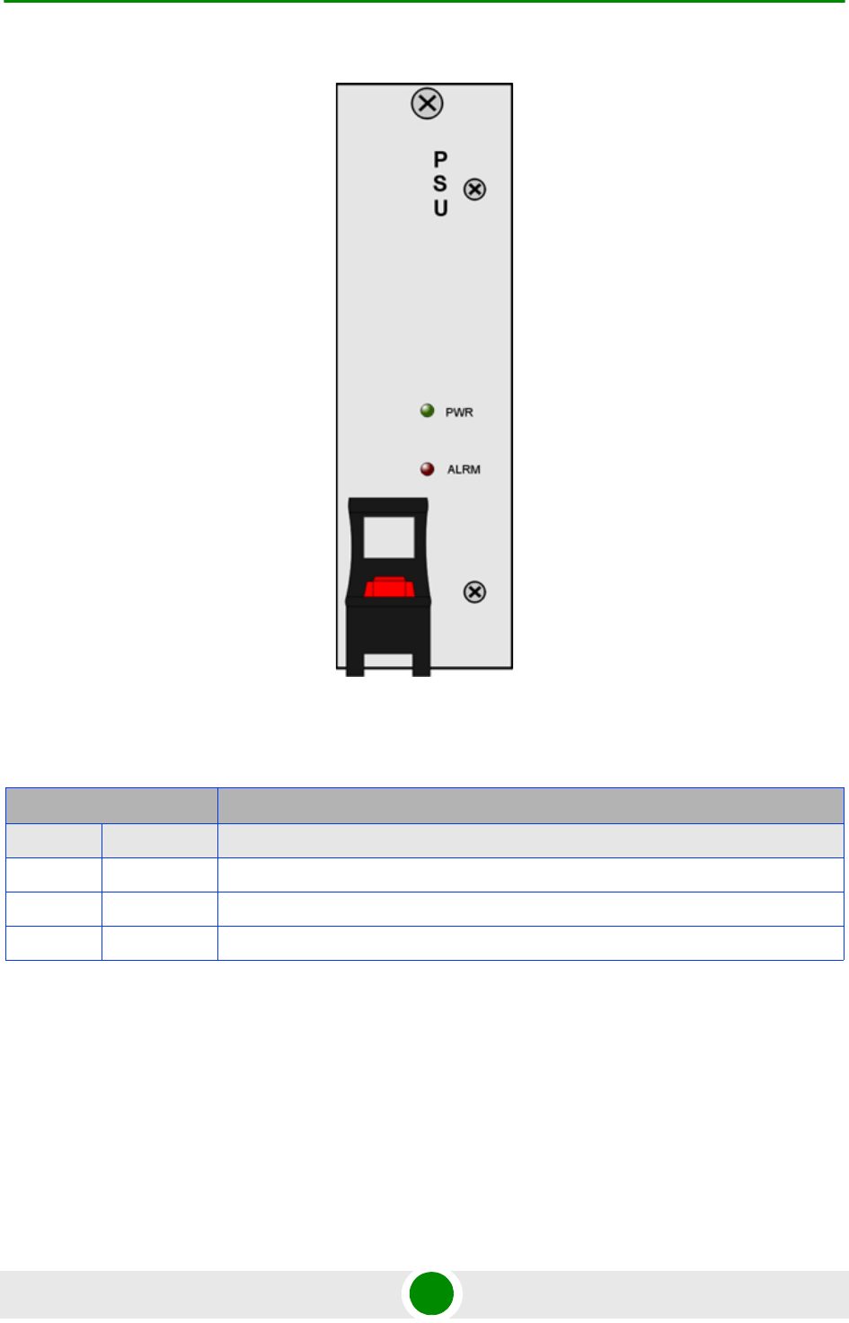
Chapter 2 - Installation Installing the Base Transceiver Station (BTS) Equipment
4Motion 80 System Manual
Figure 2-24: PSU Module Front Panel
Table 2-11: PSU LEDs
LED Status Description
PWR ALRM
Off Off No power or fatal damage
Off Red Power input is out of range or PSU is damaged or PSU is inhibited by NPU
Green Off Power is OK and PSU operates properly
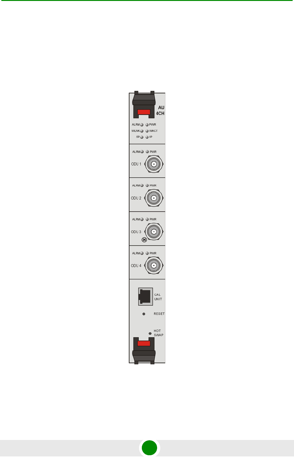
Chapter 2 - Installation Installing the Base Transceiver Station (BTS) Equipment
4Motion 81 System Manual
2.3.7 Access Unit Module (AU)
The double Euro Access Unit IDU module contains the wireless MAC and modem
that enable the establishment of wireless network connection and bandwidth
management. Each AU includes four PHY channels that can be connected to
ODUs.
Figure 2-25: AU Module Front Panel

Chapter 2 - Installation Installing the Base Transceiver Station (BTS) Equipment
4Motion 82 System Manual
Table 2-12: AU LEDs
Name Description Function
PWR Power indication Off - AU is not powered
Red - AU power supply failure (low power)
Green - AU power is OK
ALRM Alarm indication Off - AU is OK
Red - AU failure
WLINK Wireless link status indication Off - No MS is associated
Green - At least one MS is associated
WACT Transmission indication Off - No transmission
Green - Transmission OK
SP Spare Not Used
IP IP activity indication Off - No IP activity
Green (blinking) - IP activity
ODU1 - ODU4 PWR AU to ODU Power Indication Off - No AU to ODU power output
Red - AU to ODU power output failure
Green - AU to ODU power output OK
ODU1 -ODU4 ALRM AU to ODU communication
status
Off - AU-ODU communication OK
Red - AU-ODU communication failure
HOT SWAP AU readiness for hot swap
removal
Off: Power to the module is not disconnected, the
AU is not ready for removal
Blue: Power to the module can be disconnected
and the AU can be safely removed.
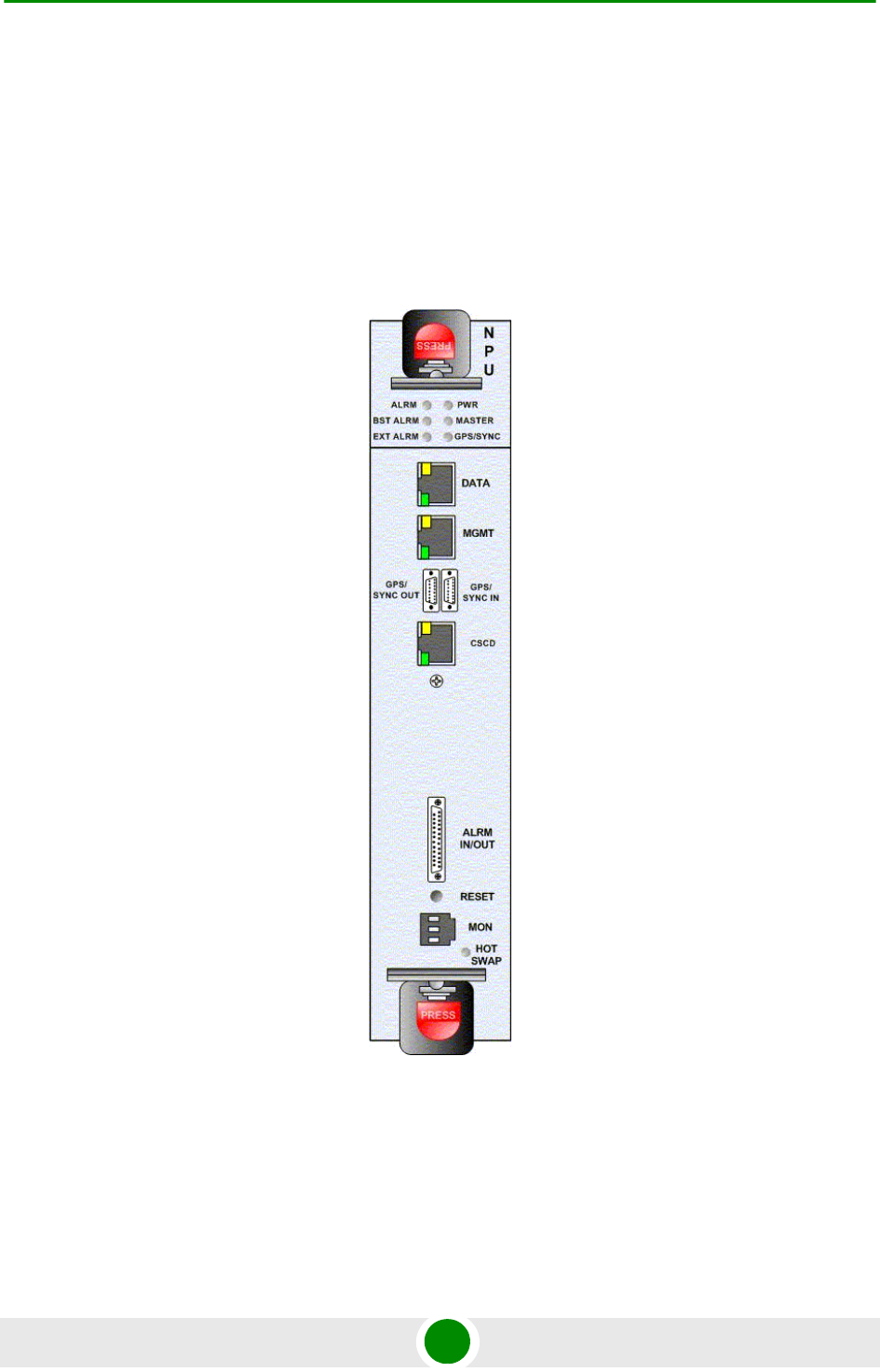
Chapter 2 - Installation Installing the Base Transceiver Station (BTS) Equipment
4Motion 83 System Manual
2.3.8 Network Processing Unit (NPU)
The NPU module serves as the central processing unit that manages the BTS's
components and the SUs served by it. It also aggregates the traffic from the AU
modules and transfers it to the IP backbone through a dedicated Gigabit/Fast
Ethernet interface. In addition, the NPU can be operated in ASN-GW mode, in
which case it also implements ASN-GW functionality.
Figure 2-26: NPU Module Front Panel

Chapter 2 - Installation Installing the Base Transceiver Station (BTS) Equipment
4Motion 84 System Manual
Table 2-13: NPU LEDS
Name Description Function
MGMT Port Activity
LED
MGMT Port Activity LED When blinking yellow indicates Ethernet activity at the
management port
MGMT Port Integrity
LED
MGMT Port Integrity LED When lit green indicates Ethernet physical layer is OK
DATA Port Activity
LED
DATA Port Activity LED When blinking yellow indicates Ethernet activity at the
data port
MGMT Port Integrity
LED
MGMT Port Integrity LED When lit green indicates Ethernet physical layer is OK
EXT ALRM External alarm indication Off - No alarm
Red - Alarm received via the ALRM IN connector
BST ALRM Cell site component
failure indication
Off - All 4Motion modules are OK
Red - Failure in one (or more) 4Motion modules
Blinking - During powering up of NPU
ALRM NPU card failure
indication
Off - NPU is OK
Red - NPU failure
Blinking - During powering up of NPU
PWR Power indication Off - NPU is not powered
Red - NPU power failure
Green - NPU power is OK
Master Master indication Lits when NPU is primary
GPS/SYNC GPS/IF clock
syncronization function
indication
Off - NPU clock is not synchronized to external source
Green - NPU clock is synchronized to external source

Chapter 2 - Installation Installing the Base Transceiver Station (BTS) Equipment
4Motion 85 System Manual
Hot Swap NPU readiness NPU card insertion status indicator
Off: Card is inserted correctly into the chassis
Blue: Card insertion is in progress or is not inserted
successfully
NPU card ejection status indicator
Off: Power to the module is not disconnected, the NPU is
not ready for removal
Blue: Power to the module can be disconnected and the
NPU can be safely removed.
Table 2-14: NPU Connectors
Name Description Function
Data RJ-45 connector Used to connect the NPU to the backbone
Cable connection to a hub/switch/router: Straight
MGMT RL-45 connector Connection to out-of-band management
Cable connection to a PC: Crossed
Cable connection to a hub/switch/router: Straight
GP/SYNC IN GPS/SYNC IN connector Enables connection to a GPS Receiver
GP/SYNC OUT GPS/SYNC OUT
connector
Supply of synchronization signals to another unit (for
future use)
ALRM IN/OUT ALARM IN/OUT
connector
Connection to external alarms
Cascade RJ-45 with two embedded
LEDs
Connection to cascade shelf
Cable connection to local management traffic
Cable connection to cascade shelf: Crossed
MON MON connector 3-pin low profile connector used for accessing the NPU
through the serial command line interface
RESET RESET Button Used to perform hardware rest to the NPU
Table 2-13: NPU LEDS
Name Description Function

Chapter 2 - Installation Installing the Base Transceiver Station (BTS) Equipment
4Motion 86 System Manual
2.3.9 Connecting the BTS Chassis and Modules
The indoor equipment should be installed as close as possible to the location
where the IF cable(s) enters the building. The location of the indoor equipment
should take into account its connection to the power source(s) and to the BTS
networking equipment.
2.3.9.1 Introduction
The BTS modules include special handles for high-force insertion/extraction of
modules. Each of the 6U high modules (NPU, AU) includes two such handles,
whereas each of the 3U high-modules (PIU, PSU) includes a single handle at the
bottom of the front panel.
The bottom injector/ejector handle of the NPU and AU modules includes a
micro-switch to support hot-swap control. Second generation PIU modules also
support hot-swap, as indicated by the HOT SWAP blue LED.
1 Attach the Cable Guide to the top panel of the chassis using the screws and
washers supplied with the Cable Guide.
2Install the chassis in a 19" cabinet. For installation in a 21" cabinet, attach
suitable ETSI rack adapters to the chassis. To provide a sufficient space for
the Cable Guide and to allow air flow for preventing over-heating, leave a free
space of at least 1U between the upper covers of the chassis and other units in
the cabinet.
3Connect one end of a grounding cable to the ground terminal located on the
rear panel of the chassis and firmly tighten the grounding screw. Connect the
opposite end of the grounding cable to a ground connection or to the cabinet, if
applicable.
4Carefully insert the modules into the relevant slots. Secure the modules in
their alloted locations.
5Place blank covers over all unused slots.
To connect the BTS chassis and modules:
NOTE
In a 3-sector configuration, it is recommended to install the AUs in slots 3, 4 and 8 (from thermal
point of view).
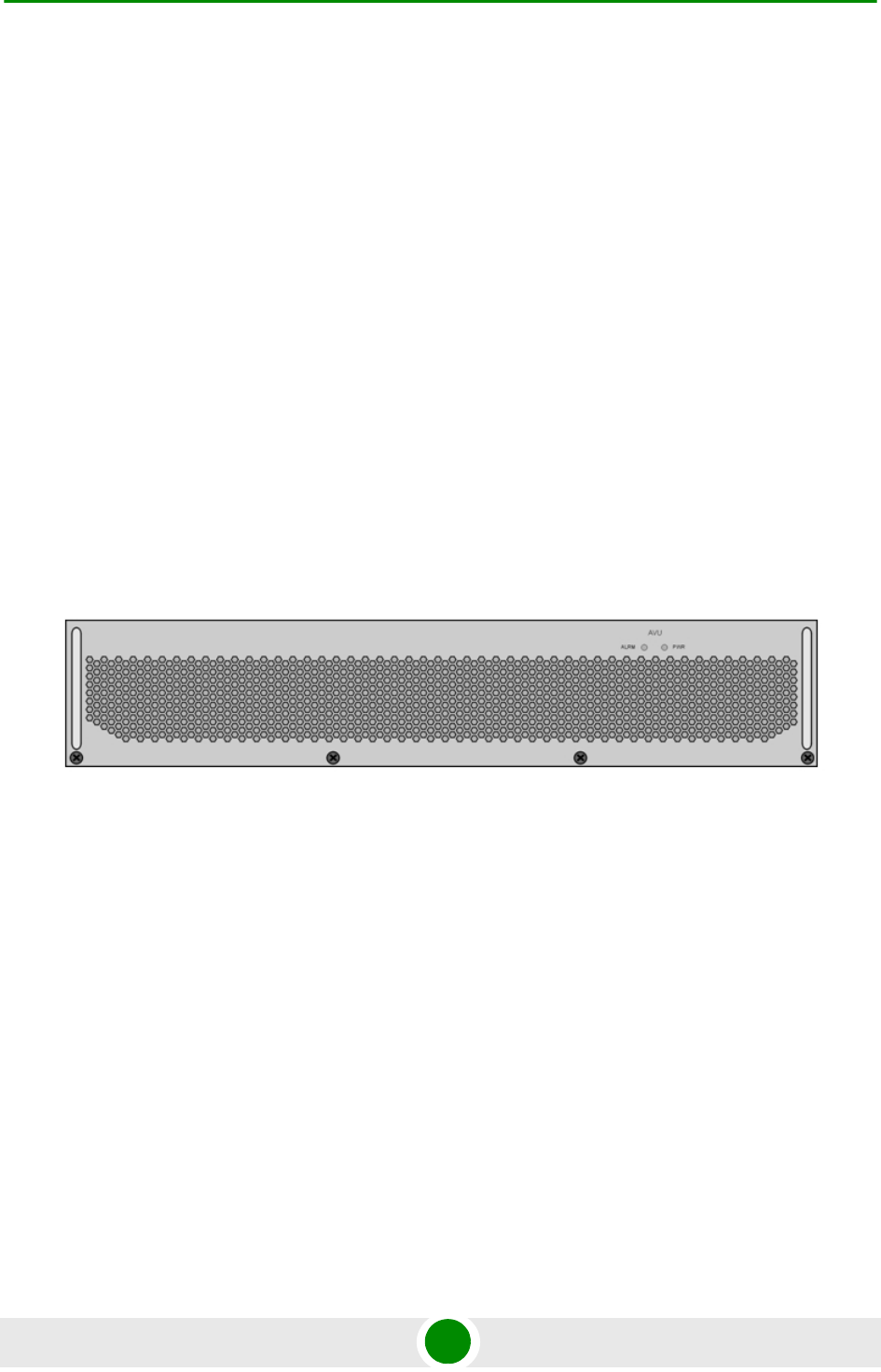
Chapter 2 - Installation Installing the Base Transceiver Station (BTS) Equipment
4Motion 87 System Manual
6Connect the DATA port of the NPU to the backbone data equipment (use a
straight Ethernet cable to connect to a hub/switch/router). The maximum
length of the Ethernet cable is 100m when operating at 100 Mbps and 70m
when operating at 1 Gbps.
7If the MGMT port is used for remote management, connect it to the
appropriate data equipment (use a straight Ethernet cable to connect to a
hub/switch/router). The maximum length of the Ethernet cable is 100m.
8Connect the DC power cable to the power jack of the PIU module. If a
redundant PIU is installed, connect a DC power cable also to the second PIU
module. Connect the power cord(s) to the -48 VDC power source(s), as follows.
»Black wire to the 48 VDC contact of the power source.
»Red wire to the + (Return) contact.
»Ground wire to the ground.
2.3.9.2 Air Ventilation Unit (AVU)
The 2U high, 84 HP wide AVU includes a 1U high integral chamber for inlet
airflow and a 1U high fan tray with an internal alarm module. To support a high
availability BTS, the fan tray includes 10 brush-less fans, where 9 fans are
sufficient for cooling a fully loaded chassis. To further support high availability,
the chassis can operate with the hot-swappable fan tray extracted from it for a
period of time sufficient for replacing it (up to 10 minutes).
Figure 2-27: AVU Drawer Front Panel

Chapter 2 - Installation Installing the Base Transceiver Station (BTS) Equipment
4Motion 88 System Manual
If the red ALRM LED is on while the PWR LED is green, it indicates a failure of at
least one fan. Although the BTS chassis may continue operating with one failed
fan, it is recommended to replace the AVU as soon as possible.
2.3.10 Replacing BTS Components
2.3.10.1 Replacing an AVU
Release the four screws securing the AVU to the chassis.
Using the handle take out the faulty chassis.
Insert a new AVU drawer and tighten the screws.
2.3.10.2 Replacing an NPU
To minimize downtime and facilitate fast and easy NPU replacement, it is
recommended to maintain an updated copy of the NPU configuration. Refer to
Section 4.3.4 for details on preparing and uploading a backup file of the NPU
configuration.
1Release the screws located on the top and bottom of the NPU's front panel.
2Press the red button of both handles until they are unlocked.
3Wait until the blue HOT SWAP LED turns on, indicating that the module has
been disconnected and can be removed.
4Press the upper handle up and the lower handle down until the module is
unlocked. Firmly hold both handles and take the module out of the chassis.
5Disconnect all IF cables connecting the AUs to the ODUs. This is necessary as
the initial configuration of the new NPU is most probably inappropriate.
Table 2-15: AVU LEDs
LED Status Description
PWR ALRM
Off Off No 5V power input
Red Red 12V power failed
Green Red One or more fans have failed
Green Off AVU operates properly
To replace an AVU drawer:

Chapter 2 - Installation Installing the Base Transceiver Station (BTS) Equipment
4Motion 89 System Manual
6Firmly push the new NPU module into its intended slot (slot 5).
7Press the upper handle up and the lower handle down simultaneously until
you hear the locking click and the red buttons are released. The blue HOT
SWAP LED will briefly turn on, indicating that the module is being powered
up.
8Secure the module in place by tightening the screws located on the top and
bottom of the front panel.
9Download the backup file using a DOS based TFTP. Use the command: tftp i
<NPU port IP address> put <file name>. The default IP address of the MGMT
port is 10.0.0.1.
10 Use the monitor program to configure the IP parameters (IP address, Subnet
Mask, Default Gateway Address) of the MGMT port. These parameters are not
affected by the loaded file.
11 Reset the system.
12 Reconnect the IF cables.
2.3.10.3 Replacing an AU
1Disconnect all IF cables connecting the AUs to ODUs.
2Release the screws at the top and the bottom of the AU's front panel.
3Press the red button of both handles until they are unlocked.
4Wait until the blue HOT SWAP LED turns on, indicating that the module has
been disconnected and can be removed.
5Press the upper handle up and the lower handle down until the module is
unlocked. Firmly hold both handles and take the module out of the chassis.
6Firmly push the new AU module into its intended slot.
7Press the upper handle up and the lower handle down simultaneously until
you hear the locking click and the red buttons are released. The blue HOT
SWAP LED will briefly turn on, indicating that the module is being powered
up.
8Secure the module in place by tightening the screws located on the top and
bottom of the front panel.
9Reconnect the IF cables. Make sure that each ODU is connected to the
appropriate port on the AU.

Chapter 2 - Installation Installing the Base Transceiver Station (BTS) Equipment
4Motion 90 System Manual
10 Wait until the AU reboot process is completed. This might take few minutes.
11 Reset the AU. (To perform the reset go to the main menu of the AU, select 2 -
Unit Control, than select 1 - Reset and confirm the reset. Alternatively, you can
press the reset button on the front panel of the AU).
12 Go to the AU main menu and check that the SW version and all parameters
are as required.
13 Check that the AU operates properly, and the SUs to which service is offered
are connected to the AU.
2.3.10.4 Replacing a PIU
1Release the screws located on the top and bottom of the PIU's front panel.
2Press the handle’s red button until the handle is unlocked.
3Wait until the blue HOT SWAP LED turns on, indicating that the module has
been disconnected and can be removed.
4Disconnect the power cable from the PIU
5Press the handle up until the module is unlocked. Firmly hold the handle and
take the module out of the chassis.
6Firmly push the new PIU module into its intended slot.
7Press the handle down until you hear the locking click and the red buttons are
released.
8Secure the module in place by tightening the screws located on the top and
bottom of the front panel.
9Connect power to the PIU only after it is fully inserted into the chassis.

Chapter 2 - Installation Installing the ODU Power Feeder
4Motion 91 System Manual
2.4 Installing the ODU Power Feeder
2.4.1 Installation Requirements
2.4.1.1 Packing List
A 19” panel can hold up to three ODU Power Feeder modules.
ODU Power Feeder module, including a DC power cable, four 0.5 meter IF
cables and four screws.
2.4.1.2 Additional Installation Requirements
A grounding cable with appropriate terminations for connecting the unit's
ground terminal to the rack or to a ground connection.
Other installation tools and materials
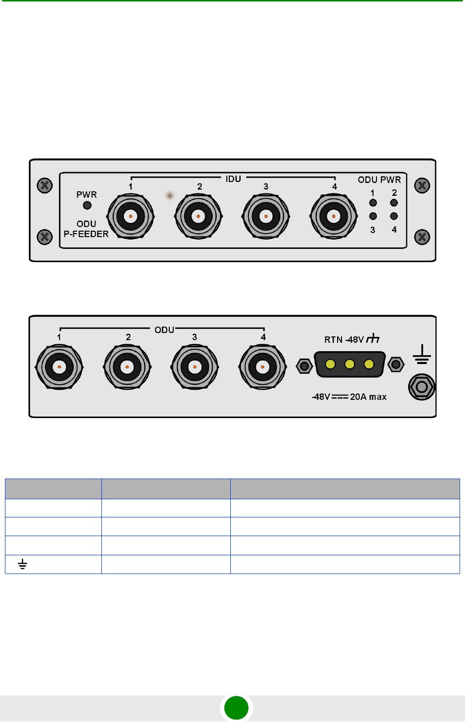
Chapter 2 - Installation Installing the ODU Power Feeder
4Motion 92 System Manual
2.4.2 The ODU Power Feeder
The ODU Power Feeder is used to provide power (-48 VDC) to the ODUs. It
transfers all signals transparently between the AU and the ODU, while injecting
DC power received from an external source. Each ODU Power Feeder unit can
serve up to four ODUs. Up to three ODU Power Feeder units can be installed in a
1U Feeder panel.
Figure 2-28: ODU Power Feeder Front Panel
Figure 2-29: ODU Power Feeder Rear Panel
Table 2-16: ODU Power Feeder Connectors
Name Connector Functional
IDU 1 - 4 4 x TNC jacks Connection to ODU connectors of AUs
ODU 1 - 4 4 x TNC jacks Connections to IF connectors of ODU units
-48V 3-pin D-Type power jack Connection to DC power source
(GND) Grounding Screw Connection to ground (earth)

Chapter 2 - Installation Installing the ODU Power Feeder
4Motion 93 System Manual
2.4.2.1 Preparing a Power Cable
A 2.5m DC power cable is supplied with each ODU Power Feeder module.
Additional DC cables can be ordered from Alvarion. If necessary, use the following
instruction to prepare a DC cable.
1Use a cable capable of supporting a current of at least 10A. Use a cable with
2 x 10AWG (or thicker) wires for the power plus an additional 10AWG to
20AWG ground wire.
2The matching power connector to be used is Amphenol D-type power P/N
177TWA/3W3/SP3Y with high power socket contacts P/N 17DM53744-1.
3Connect the cable to the power connector as follows:
»Pin 1 (RTN): Red (10 AWG min wire)
»Pin 2 (-48V): Black (10 AWG min wire)
»Pin 3 ( ): Ground (shield) (10AWG-20AWG wire)
4Attach suitable terminal rings to the side that connects to the power source.
2.4.3 Installing the ODU Power Feeder
The ODU Power Feeder should be installed as close as possible to the location
where the IF cable(s) enters the building. The location of the ODU Power Feeder
should take into consideration its connection to the power source and to the BTS
equipment.
Table 2-17: ODU Power Feeder LEDs
Name Description Functionality
PWR Input power indication Off - ODU Power Feeder is not powered
Green - ODU Power Feeder power is OK
ODU PWR 1 - 4 Output power indications Off - ODU is not connected
Red - Power output problem (short or overload)
Green - ODU is connected and powered
To prepare the power cable:

Chapter 2 - Installation Installing the ODU Power Feeder
4Motion 94 System Manual
1The panel is supplied with blank covers. Release the nuts on the rear side of
the panels to remove the blank cover(s) you want to replace with ODU Power
Feeder module(s). Attach the ODU Power Feeder module(s) to the panel using
the four screws supplied with each module.
2Place the panel with the ODU Power Feeder module(s) on a shelf/desk or
install it in a 19" cabinet, next to the BTS equipment.
3Connect one end of a grounding cable to the grounding screw located on the
rear panel of each ODU Power Feeder module and firmly tighten the grounding
screw. Connect the other end of the grounding cable(s) to a ground (earth)
connection or to the cabinet, if applicable.
4Connect the IDU connector(s) to the appropriate ODU connector(s) of the AU(s)
using the short (0.5 meter) IF cables supplied with the module.
5Connect the power cord to the ODU Power Feeder’s DC socket, located on the
rear panel. Connect the other end of the power cord to the -48 VDC power
source.
6Connect the IF cable(s) to the appropriate ODU connector(s).The other end is
already connected connected to the ODU(s). To avoid transmissions at
undesired frequencies, verify that the frequency and bandwidth parameters
are properly configured before connecting the IF cables.
To install the ODU Power Feeder:

Chapter 2 - Installation Installing the Outdoor GPS Receiver
4Motion 95 System Manual
2.5 Installing the Outdoor GPS Receiver
Perform the following steps to install the Outdoor GPS Receiver
1Place the bracket on a flat surface and thread the supplied pipe through the
bracket hole and into the GPS antenna. Hand-tighten until snug. Do not
over-tighten or use a tool. Make sure that the connector (male) is on the open
side of the bracket.
2Assemble the surge protection cable onto the bracket using the supplied
screws, washers, and spring washers (2x1032). Apply torque 2.1 [N*m] (19.2
[lbs*in]). Make sure that the female connector faces the antenna.
3Use a 1032 screw, washer, and spring washer to connect the surge protector’s
grounding cable to the bracket. Apply torque 2.1 [N*m] (19.2 [lbs*in]).
4Connect the surge protector cable (female connector) to the GPS antenna
connector (male). Use the groove on the cable connector (indicatd by an arrow)
as a guide. It aligns with the tenon in the connector on the GPS side. Turn the
locking ring on the cable connector clockwise to secure the connection. Do not
over-tighten.
5Use the supplied clamps to assemble the GPS and bracket on a pole. Use the
M8 nuts, washers, and spring washers to lock the clamps to the bracket.
Apply torque 9 [N*m] (80 [lbs*in]).

Chapter 2 - Installation Connecting the GPS Cables
4Motion 96 System Manual
2.6 Connecting the GPS Cables
The Outdoor GPS Receiver is connected to the GPS/SYNC IN connector. Before
connecting the cable, make sure that the length of the cable is sufficient to reach
the NPU.
1Connect the 12-pin round connector (female) of the Cat. 5E Ethernet cable to
the male connector of the surge protector. Use the groove on the cable
connector (indicated by an arrow) as a guide. It aligns with the tenon in the
connector on the surge protector side. Turn the locking ring on the cable
connector clockwise to secure the connection. Do not over-tighten.
2Fix the cable onto the pole using a cable strip. Route the cable to the location
selected for the indoor equipment.
3Crimp the other end of the Cat. 5E Ethernet cable with an RJ-45 connector
and connect it to the indoor GPS adapter cable. Connect the other end of the
indoor GPS adapter cable to GPS/SYNC IN connector.
To connect the Ethernet cable: