Alvarion Technologies BMAX-OR-25 BreezeMax 4Motion Broadband Wireless System User Manual 4Motion System Manual
Alvarion Technologies Ltd. BreezeMax 4Motion Broadband Wireless System 4Motion System Manual
Contents
- 1. Manual 1
- 2. Manual 2
- 3. Manual 3
- 4. Manual 4
- 5. Manual
Manual 4

Chapter 4 - Operation and Administration Using the CLI Managing BSs
4Motion 682 System Manual
4.8.19.5.12 Displaying Configuration Information for All Airframe Parameters
To display configuration for all Airframe parameters, run the following command:
npu# show airframe-all bs [<(1 to 16777215 StepSize 1)>]
Specify the BS ID if you want to display configuration for a particular BS. For
example, to display all Airframe parameters of BS 66503, run the following
command:
npu# show airframe-all bs 66053
Do not specify the BS ID if you want to view configuration information for all
existing BSs. To display information for all BSs, run the following command:
npu# show airframe-all bs
Syntax
Description Parameter Description Presence Default
Value
Possible
Values
<(1 to 16777215
StepSize 1)>
The BS ID
Specify a value for this
parameter if you want to
display the Airframe Dynamic
Permutation parameters of a
specific BS. Do not specify a
value for this parameter if you
want to display the Airframe
Dynamic Permutation
parameters of all BSs.
Optional N/A 1-16777215
Display
Format
(for each
existing
Neighbour
BS in each
of the
existing BSs
if requested
for all)
BSIDLSB :<value>
DownlinkPermutationBase :<value>
UplinkPermutationBase :<value>
Command
Modes
Global command mode

Chapter 4 - Operation and Administration Using the CLI Managing BSs
4Motion 683 System Manual
4.8.20 Managing Rate Adaptation Parameters
After enabling the BS configuration mode, you can execute the following tasks:
Configure one or more of the Rate Adaptation parameters (refer to
Section 4.8.20.1).
Restore the default values of some or all of the Rate Adaptation parameters
(refer to Section 4.8.20.2).
You can display configuration information for the Rate Adaptation parameters of a
selected or all existing BSs (refer to Section 4.8.20.3).
4.8.20.1 Configuring Rate Adaptation Parameters
From the BS configuration mode, run the following command:
Command
Syntax
npu# show airframe-all bs [<(1 to 16777215 StepSize 1)> ]
Privilege
Level
10
Syntax
Description Parameter Description Presence Default
Value
Possible
Values
<(1 to 16777215
StepSize 1)>
The BS ID
Specify a value for this
parameter if you want to
display all Airframe
parameters of a specific BS.
Do not specify a value for this
parameter if you want to
display all Airframe
parameters of all BSs.
Optional N/A 1-16777215
Command
Modes
Global command mode
To configure the Rate Adaptation parameters:

Chapter 4 - Operation and Administration Using the CLI Managing BSs
4Motion 684 System Manual
npu(config-bs-66053)# rateadapt-general [dl-basicrate
{ctcQpskOneOverTwoTimesSix | ctcQpskOneOverTwoTimesFour |
ctcQpskOneOverTwoTimesTwo | ctcQpskOneOverTwo | ctcQpskThreeOverFour |
ctcQamSixteenOneOverTwo | ctcQamSixteenThreeOverFour |
ctcQamSixtyFourOneOverTwo | ctcQamSixtyFourTwoOverThree |
ctcQamSixtyFourThreeOverFour | ctcQamSixtyFourFiveOverSix}] [ul-basicrate
{ctcQpskOneOverTwoTimesSix | ctcQpskOneOverTwoTimesFour |
ctcQpskOneOverTwoTimesTwo | ctcQpskOneOverTwo | ctcQpskThreeOverFour
|ctcQamSixteenOneOverTwo | ctcQamSixteenThreeOverFour |
ctcQamSixtyFourOneOverTwo | ctcQamSixtyFourTwoOverThree |
ctcQamSixtyFourThreeOverFour | ctcQamSixtyFourFiveOverSix}]
[mincinr-qpsk-1by2-rep6 <(-20 to 30 StepSize 0.1)>] [mincinr-qpsk-1by2-rep4
<(-20 to 30 StepSize 0.1)>] [mincinr-qpsk-1by2-rep2 <(-20 to 30 StepSize 0.1)>]
[mincinr-qpsk-1by2 <(-20 to 30 StepSize 1)>] [mincinr-qpsk-3by4 <(-20 to 30
StepSize 1)>] [mincinr-qam16-1by2 <(-20 to 30 StepSize 0.1)>]
[mincinr-qam16-3by4 <(-20 to 30 StepSize 0.1)>] [mincinr-qam64-1by2 <(-20 to
30 StepSize 0.1)>] [mincinr-qam64-2by3 <(-20 to 30 StepSize 0.1)>]
[mincinr-qam64-3by4 <(-20 to 30 StepSize 0.1)>] [mincinr-qam64-5by6 <(-20 to
30 StepSize 0.1)>]
Command
Syntax
npu(config-bs-66053)# [dl-basicrate {ctcQpskOneOverTwoTimesSix |
ctcQpskOneOverTwoTimesFour | ctcQpskOneOverTwoTimesTwo |
ctcQpskOneOverTwo | ctcQpskThreeOverFour | ctcQamSixteenOneOverTwo
| ctcQamSixteenThreeOverFour | ctcQamSixtyFourOneOverTwo |
ctcQamSixtyFourTwoOverThree | ctcQamSixtyFourThreeOverFour |
ctcQamSixtyFourFiveOverSix} ] [ul-basicrate
{ctcQpskOneOverTwoTimesSix | ctcQpskOneOverTwoTimesFour |
ctcQpskOneOverTwoTimesTwo | ctcQpskOneOverTwo |
ctcQpskThreeOverFour |ctcQamSixteenOneOverTwo |
ctcQamSixteenThreeOverFour | ctcQamSixtyFourOneOverTwo |
ctcQamSixtyFourTwoOverThree | ctcQamSixtyFourThreeOverFour |
ctcQamSixtyFourFiveOverSix} ] [mincinr-qpsk-1by2-rep6 <(-20 to 30
StepSize 0.1)> ] [mincinr-qpsk-1by2-rep4 <(-20 to 30 StepSize
0.1)> ] [mincinr-qpsk-1by2-rep2 <(-20 to 30 StepSize 0.1)> ]
[mincinr-qpsk-1by2 <(-20 to 30 StepSize 1)> ] [mincinr-qpsk-3by4
<(-20 to 30 StepSize 1)> ] [mincinr-qam16-1by2 <(-20 to 30
StepSize 0.1)> ] [mincinr-qam16-3by4 <(-20 to 30 StepSize 0.1)> ]
[mincinr-qam64-1by2 <(-20 to 30 StepSize 0.1)> ]
[mincinr-qam64-2by3 <(-20 to 30 StepSize 0.1)> ]
[mincinr-qam64-3by4 <(-20 to 30 StepSize 0.1)> ]
[mincinr-qam64-5by6 <(-20 to 30 StepSize 0.1)> ]

Chapter 4 - Operation and Administration Using the CLI Managing BSs
4Motion 685 System Manual
Privilege
Level
10
Syntax
Description Parameter Description Presence Default
Value Possible Values
dl-basicrate
{ctcQpskOneOverTwo
TimesSix |
ctcQpskOneOverTwo
TimesFour |
ctcQpskOneOverTwo
TimesTwo |
ctcQpskOneOverTwo
|
ctcQpskThreeOverFo
ur |
ctcQamSixteenOneO
verTwo |
ctcQamSixteenThree
OverFour |
ctcQamSixtyFourOne
OverTwo |
ctcQamSixtyFourTwo
OverThree |
ctcQamSixtyFourThre
eOverFour |
ctcQamSixtyFourFive
OverSix}
The downlink basic
rate
Optional ctcQpskO
neOverTw
oTimesSix
ctcQpskOneOverTw
oTimesSix
ctcQpskOneOverTw
oTimesFour
ctcQpskOneOverTw
oTimesTwo
ctcQpskOneOverTw
o
ctcQpskThreeOverF
our
ctcQamSixteenOne
OverTwo
ctcQamSixteenThree
OverFour
ctcQamSixtyFourOn
eOverTwo
ctcQamSixtyFourTw
oOverThree
ctcQamSixtyFourThr
eeOverFour
ctcQamSixtyFourFiv
eOverSix

Chapter 4 - Operation and Administration Using the CLI Managing BSs
4Motion 686 System Manual
ul-basicrate
{ctcQpskOneOverTwo
TimesSix |
ctcQpskOneOverTwo
TimesFour |
ctcQpskOneOverTwo
TimesTwo |
ctcQpskOneOverTwo
|
ctcQpskThreeOverFo
ur |
ctcQamSixteenOneO
verTwo |
ctcQamSixteenThree
OverFour |
ctcQamSixtyFourOne
OverTwo |
ctcQamSixtyFourTwo
OverThree |
ctcQamSixtyFourThre
eOverFour |
ctcQamSixtyFourFive
OverSix}
The uplink basic
rate
Optional ctcQpskO
neOverTw
o
ctcQpskOneOverTw
oTimesSix
ctcQpskOneOverTw
oTimesFour
ctcQpskOneOverTw
oTimesTwo
ctcQpskOneOverTw
o
ctcQpskThreeOverF
our
ctcQamSixteenOne
OverTwo
ctcQamSixteenThree
OverFour
ctcQamSixtyFourOn
eOverTwo
ctcQamSixtyFourTw
oOverThree
ctcQamSixtyFourThr
eeOverFour
ctcQamSixtyFourFiv
eOverSix
mincinr-qpsk-1by2-re
p6 <(-20 to 30
StepSize 0.1)>
The minimal CINR
in dB Required to
allow QPSK 1/2
Repetition 6 Uplink
transmissions.
Cannot be higher
than
mincinr-qpsk-1by2-
rep4
Optional -20 -20 to 30 in steps of 0.1

Chapter 4 - Operation and Administration Using the CLI Managing BSs
4Motion 687 System Manual
mincinr-qpsk-1by2-re
p4 <(-20 to 30
StepSize 0.1)>
The minimal CINR
in dB Required to
allow QPSK 1/2
Repetition 4 Uplink
transmissions.
Must be in the
range from
mincinr-qpsk-1by2-
rep6 to
mincinr-qpsk-1by2-
rep2
Optional -20 -20 to 30 in steps of 0.1
mincinr-qpsk-1by2-re
p2 <(-20 to 30
StepSize 0.1)>
The minimal CINR
in dB Required to
allow QPSK 1/2
Repetition 2 Uplink
transmissions.
Must be in the
range from
mincinr-qpsk-1by2-
rep4 to
mincinr-qpsk-1by2
Optional -20 -20 to 30 in steps of 0.1
mincinr-qpsk-1by2
<(-20 to 30 StepSize
0.1)>
The minimal CINR
in dB Required to
allow QPSK 1/2
Uplink
transmissions.
Must be in the
range from
mincinr-qpsk-1by2-
rep2 to
mincinr-qpsk-3by4
Optional -20 -20 to 30 in steps of 0.1
mincinr-qpsk-3by4
<(-20 to 30 StepSize
0.1)>
The minimal CINR
in dB Required to
allow QPSK 3/4
Uplink
transmissions.
Must be in the
range from
mincinr-qpsk-1by2
to
mincinr-qam16-1by
2
Optional -20 -20 to 30 in steps of 0.1

Chapter 4 - Operation and Administration Using the CLI Managing BSs
4Motion 688 System Manual
mincinr-qam16-1by2
<(-20 to 30 StepSize
0.1)>
The minimal CINR
in dB Required to
allow 16QAM 1/2
Uplink
transmissions.
Must be in the
range from
mincinr-qpsk-3by4
to
mincinr-qam16-3by
4
Optional -20 -20 to 30 in steps of 0.1
mincinr-qam16-3by4
<(-20 to 50 StepSize
1)>
The minimal CINR
in dB Required to
allow 16QAM 3/4
Uplink
transmissions.
Must be in the
range from
mincinr-qam16-1by
2 to
mincinr-qam64-1by
2
Optional -20 -20 to 30 in steps of 0.1
mincinr-qam64-1by2
<(-20 to 30 StepSize
0.1)>
The minimal CINR
in dB Required to
allow 64QAM 1/2
Uplink
transmissions.
Must be in the
range from
mincinr-qam16-3by
4 to
mincinr-qam64-2by
3
Optional -20 -20 to 30 in steps of 0.1
mincinr-qam64-2by3
<(-20 to 30 StepSize
0.1)>
The minimal CINR
in dB Required to
allow 64QAM 2/3
Uplink
transmissions.
Must be in the
range from
mincinr-qam64-1by
2 to
mincinr-qam64-3by
4
Optional -20 -20 to 30 in steps of 0.1

Chapter 4 - Operation and Administration Using the CLI Managing BSs
4Motion 689 System Manual
4.8.20.2 Restoring the Default Values of Rate Adaptation Parametes
To restore the default values of some or all of the Rate Adaptation parameters, run
the following command:
npu(config-bs-66053)# no rateadapt-general [dl-basicrate] [ul-basicrate]
[mincinr-qpsk-1by2-rep6] [mincinr-qpsk-1by2-rep4] [mincinr-qpsk-1by2-rep2 >]
[mincinr-qpsk-1by2] [mincinr-qpsk-3by4] [mincinr-qam16-1by2]
[mincinr-qam16-3by4] [mincinr-qam64-1by2] [mincinr-qam64-2by3]
[mincinr-qam64-3by4] [mincinr-qam64-5by6]
You can restore only some parameters to their default values by specifying only
those parameters. For example, to restore only the ul-basicrate parameter to the
default value, run the following command:
npu(config-bs-66053)# no rateadapt-general ul-basicrate
mincinr-qam64-3by4
<(-20 to 30 StepSize
0.1)>
The minimal CINR
in dB Required to
allow 64QAM 3/4
Uplink
transmissions.
Must be in the
range from
mincinr-qam64-2by
3 to
mincinr-qam64-5by
6
Optional -20 -20 to 30 in steps of 0.1
mincinr-qam64-5by6
<(-20 to 30 StepSize
0.1)>
The minimal CINR
in dB Required to
allow 64QAM 5/6
Uplink
transmissions.
Cannot be lower
than
mincinr-qam64-3by
4
Optional -20 -20 to 30 in steps of 0.1
Command
Modes
bs configuration mode
IMPORTANT
When creating a new BS, at least one of the Rate Adaptation parameters must be configured
explicitly (even if configured to the default value).

Chapter 4 - Operation and Administration Using the CLI Managing BSs
4Motion 690 System Manual
This parameter will be restored to its default value, while the other parameters
will remain unchanged.
To restore all Rate Adaptation parameters to their default value, run the following
command:
npu(config-bs-66053)# no rateadapt-general
4.8.20.3 Displaying Configuration for Rate Adaptation Parameters
To display configuration information of Rate Adaptation parameters, run the
following command:
npu# show rateadapt-general bs [<(1 to 16777215 StepSize 1)
Specify the BS ID if you want to display information for a particular BS. For
example, to display the Rate Adaptation parameters of BS 66053, run the
following command:
npu# show rateadapt-general bs 66053
Do not specify this parameter if you want to view information for all existing BSs.
To display information for all BSs, run the following command:
npu# show rateadapt-general bs
NOTE
Refer to Section 4.8.20.1 for a description and default values of these parameters.
Command
Syntax
npu(config-bs-66053)# rateadapt-general [dl-basicrate ] [ul-basicrate
] [mincinr-qpsk-1by2-rep6 ] [mincinr-qpsk-1by2-rep4 ]
[mincinr-qpsk-1by2-rep2 > ] [mincinr-qpsk-1by2 ]
[mincinr-qpsk-3by4 ] [mincinr-qam16-1by2 ] [mincinr-qam16-3by4 ]
[mincinr-qam64-1by2 ] [mincinr-qam64-2by3 ] [mincinr-qam64-3by4 ]
[mincinr-qam64-5by6 ]
Privilege
Level
10
Command
Modes
bs configuration mode

Chapter 4 - Operation and Administration Using the CLI Managing BSs
4Motion 691 System Manual
Command
Syntax
npu# show rateadapt-general bs [<(1 to 16777215 StepSize 1)
Privilege
Level
1
Syntax
Description Parameter Description Presence Default
Value
Possible
Values
<(1 to 16777215
StepSize 1)>
The BS ID
Specify a value for this
parameter if you want to
display Rate Adaptation
parameters of a specific BS.
Do not specify a value for this
parameter if you want to
display Rate Adaptation
parameters of all BSs.
Optional N/A 1-16777215
Display
Format
(for each
existing BS
if requested
for all BSs)
BSIDLSB :<value>
DownlinkBasicRate :<value>
UplinkBasicRate :<value>
MinCinrQpskCtc1/2Rep6 :<value>
MinCINRQpskCtc1/2Rep4 :<value>
MinCINRQpskCtc1/2Rep2 :<value>
MinCINRQpskCtc1/2 :<value>
MinCINRQpskCtc3/4 :<value>
MinCINRQam16Ctc1/2 :<value>
MinCINRQam16Ctc3/4 :<value>
MinCINRQam64Ctc1/2 :<value>
MinCINRQam64Ctc2/3 :<value>
MinCINRQam64Ctc3/4 :<value>
MinCINRQam64Ctc5/6 :<value>

Chapter 4 - Operation and Administration Using the CLI Managing BSs
4Motion 692 System Manual
4.8.21 Managing BS Bearer Interface Parameters
After enabling the BS configuration mode, you can execute the following tasks:
Configure one or more of the Bearer Interface parameters (refer to
Section 4.8.21.1).
Restore the default values of some or all of the Bearer Interface parameters
(refer to Section 4.8.21.2).
You can display configuration information for the Bearer Interface parameters of a
selected or all existing BSs (refer to Section 4.8.21.3).
4.8.21.1 Configuring Bearer Interface Parameters
From the BS configuration mode, run the following command:
npu(config-bs-66053)# bearer [ip-address <ip address>] [ip-subnetmask <ip
address>] [dflt-gw <ip address>] [mtu-size <(1500 to 9000 StepSize 1)>]
[linkusage-hardthrshld <(0 to100 StepSize 1)>]
Command
Modes
Global command mode
To configure the Bearer Interface Parameters:
Command
Syntax
npu(config-bs-66053)# bearer [ip-address <ip address> ]
[ip-subnetmask <ip address> ] [dflt-gw <ip address> ] [mtu-size
<(1500 to 9000 StepSize 1)> ] [linkusage-hardthrshld <(0 to100
StepSize 1)> ]
Privilege
Level
10
Syntax
Description Parameter Description Presence Defaul
t Value Possible
Values
[ip-address <ip address>
]
The IP address of the
bearer interface of the
BS
Mandatory
when creating a
new BSl
N/A IP address

Chapter 4 - Operation and Administration Using the CLI Managing BSs
4Motion 693 System Manual
4.8.21.2 Restoring the Default Values of Bearer Interface Parametes
To restore the default values of some or all of the Bearer Interface parameters, run
the following command:
npu(config-bs-66053)# no bearer [mtu-size] [linkusage-hardthrshld]
You can restore only one parameter to the default values by specifying only that
parameters. For example, to restore only the mtu-size parameter to the default
value, run the following command:
npu(config-bs-66053)# no bearer mtu-size
This parameter will be restored to its default value, while the other parameter will
remain unchanged.
To restore all Bearer Interface parameters to their default value, run the following
command:
npu(config-bs-66053)# no bearer
[ip-subnetmask <ip
address> ]
The IP subnet mask of
the bearer interface of
the BS
Mandatory
when creating a
new BSl
N/A Subnet mask
[dflt-gw <ip address> ] The IP address of the
default gateway of the
bearer interface of the
BS
Mandatory
when creating a
new BSl
N/A IP address
[mtu-size <(1500 to 9000
StepSize 1)> ]
MTU size (in bytes) of
the bearer interface of
the BS
Optional 1500 1500 - 9000
[linkusage-hardthrshld
<(0 to 100 StepSize 1)> ]
The BS backplane
usage hard limit
threshold, in
percecents. An alarm if
sent if either uplink or
downlink backplane
link usage exceeds the
threshold.
Optional 80 0 - 100
Command
Modes
bs configuration mode
IMPORTANT
When creating a new BS, the Bearer Interface mandatory parameters must be configured.

Chapter 4 - Operation and Administration Using the CLI Managing BSs
4Motion 694 System Manual
4.8.21.3 Displaying Configuration Information for Bearer Interface
Parameters
To display configuration information of Bearer Interface parameters, run the
following command:
npu# show bearer bs [<(1 to 16777215 StepSize 1)
Specify the BS ID if you want to display information for a particular BS. For
example, to display the Bearer Interface parameters of BS 66053, run the
following command:
npu# show bearer bs 66053
Do not specify this parameter if you want to view information for all existing BSs.
To display information for all BSs, run the following command:
npu# show bearer bs
NOTE
Refer to Section 4.8.21.1 for a description and default values of these parameters.
Command
Syntax
npu(config-bs-66053)# no bearer [mtu-size ] [linkusage-hardthrshld ]
Privilege
Level
10
Command
Modes
bs configuration mode
Command
Syntax
npu# show bearer bs [<(1 to 16777215 StepSize 1)
Privilege
Level
1

Chapter 4 - Operation and Administration Using the CLI Managing BSs
4Motion 695 System Manual
4.8.22 Managing Authentication Relay Parameters
After enabling the BS configuration mode, you can execute the following tasks:
Configure one or more of the Authentication parameters (refer to
Section 4.8.22.1).
Restore the default values of some or all of the Authentication non-mandatory
parameters (refer to Section 4.8.22.2).
You can display configuration information for the Authentication parameters of a
selected or all existing BSs (refer to Section 4.8.22.3).
Syntax
Description Parameter Description Presence Default
Value
Possible
Values
<(1 to 16777215
StepSize 1)>
The BS ID
Specify a value for this
parameter if you want to
display Bearer Interface
parameters of a specific BS.
Do not specify a value for this
parameter if you want to
display Bearer Interface
parameters of all BSs.
Optional N/A 1-16777215
Display
Format
(for each
existing BS
if requested
for all BSs)
BSIDLSB :<value>
IPAddress :<value>
IPsubnetMask :<value>
DefaultGateway :<value>
MTUSize :<value>
LinkUsageHardThreshold(%) :<value>
Command
Modes
Global command mode

Chapter 4 - Operation and Administration Using the CLI Managing BSs
4Motion 696 System Manual
4.8.22.1 Configuring Authentication Parameters
From the BS configuration mode, run the following command:
npu(config-bs-66053)# auth-general [dflt-auth-ip-address <ip address>]
[suspendedeapprocthrshld <(0 to 10000 StepSize 1)>] [activemsthrshld <(0 to
1024 StepSize 1)>] [maxeaproundsthrshld <(0 to 100 StepSize 1)>]
[nonauth-macctrlratethrshld <(0 to 120000 StepSize 1)>]
[nonauth-pduratethrshld <(0 to 120000 StepSize 1)>]
To configure the Authentication parameters:
Command
Syntax
npu(config-bs-66053)# auth-general [dflt-auth-ip-address <ip address>
] [suspendedeapprocthrshld <(0 to 10000 StepSize 1)> ]
[activemsthrshld <(0 to 1024 StepSize 1)> ] [maxeaproundsthrshld
<(0 to 100 StepSize 1)> ] [nonauth-macctrlratethrshld <(0 to
120000 StepSize 1)> ] [nonauth-pduratethrshld <(0 to 120000
StepSize 1)> ]
Privilege
Level
10
Syntax
Description Parameter Description Presence Default
Value Possible
Values
[dflt-auth-ip-address
<ip address> ]
Identifier (IP address) of
“default” authenticator
ASN GW.
Mandatory
when
creating a
new BS.
N/A IPv4 address
[suspendedeapprocth
rshld <(0 to 10000
StepSize 1)> ]
Suspended EAP
authentification process
threshold. It is used to set
an alarm.
Optional 0 0 to 10000

Chapter 4 - Operation and Administration Using the CLI Managing BSs
4Motion 697 System Manual
[activemsthrshld <(0
to 1024 StepSize 1)> ]
Threshold for the number
of MSs in active operation
state (not Idle) served by
the BS. Exceeding this
threshold will set the
alarm “Excessive MS
number”.
A value of 0 means that
the alarm is disabled.
Optional 0 0 to 1024
[maxeaproundsthrshl
d <(0 to 100 StepSize
1)> ]
Threshold for the number
of EAP rounds in one
direction in the same EAP
session. When exceeding
this threshold; alarm is
set. May be used to
protect the system from
hazard EAP sessions with
extreme number of
messaging round trips. A
value of "0" means the
alarm is disabled.
A value of 0 means that
the alarm is disabled.
Optional 0 0 to 100
[nonauth-macctrlratet
hrshld <(0 to 120000
StepSize 1)> ]
Threshold for alarm for
exceeding non-authentic
MAC control rate, in Kbps
A value of 0 means that
the alarm is disabled.
Optional 0 0 to 120000
[nonauth-pduratethrsh
ld <(0 to 120000
StepSize 1)> ]
Threshold for alarm for
exceeding non-authentic
PDU rate (in Kbps).
A value of 0 means that
the alarm is disabled.
Optional 0 0 to 120000
Command
Modes
bs configuration mode
IMPORTANT
When creating a new BS, the Authentication dflt-auth-ip-address mandatory parameter must be
configured.

Chapter 4 - Operation and Administration Using the CLI Managing BSs
4Motion 698 System Manual
4.8.22.2 Restoring the Default Values of Authentication Parametes
To restore the default values of some or all of the Authentication parameters, run
the following command:
npu(config-bs-66053)# no auth-general [suspendedeapprocthrshld]
[activemsthrshld] [maxeaproundsthrshld] [nonauth-macctrlratethrshld]
[nonauth-pduratethrshld]
You can restore only some parameters to their default values by specifying only
those parameters. For example, to restore only the activemsthrshld and
maxeaproundsthrshld parameters to the default values, run the following
command:
npu(config-bs-66053)# no auth-general activemsthrshld
maxeaproundsthrshld
These parameters will be restored to their default values, while the other
parameters will remain unchanged.
To restore all Authentication parameters to their default value, run the following
command:
npu(config-bs-66053)# no auth-general
4.8.22.3 Displaying Configuration Information for Authentication
Parameters
To display configuration information of Authentication parameters, run the
following command:
NOTE
Refer to Section 4.8.22.1 for a description and default values of these parameters.
Command
Syntax
npu(config-bs-66053)# no auth-general [suspendedeapprocthrshld ]
[activemsthrshld ] [maxeaproundsthrshld ]
[nonauth-macctrlratethrshld ] [nonauth-pduratethrshld ]
Privilege
Level
10
Command
Modes
bs configuration mode

Chapter 4 - Operation and Administration Using the CLI Managing BSs
4Motion 699 System Manual
npu# show auth-general bs [<(1 to 16777215 StepSize 1)
Specify the BS ID if you want to display information for a particular BS. For
example, to display the Authentication parameters of BS 66053, run the following
command:
npu# show auth-general bs 66053
Do not specify this parameter if you want to view information for all existing BSs.
To display information for all BSs, run the following command:
npu# show auth-general bs
Command
Syntax
npu# show auth-general bs [<(1 to 16777215 StepSize 1)
Privilege
Level
1
Syntax
Description Parameter Description Presence Default
Value
Possible
Values
<(1 to 16777215
StepSize 1)>
The BS ID
Specify a value for this
parameter if you want to
display Authentication
parameters of a specific BS.
Do not specify a value for this
parameter if you want to
display Authentication
parameters of all BSs.
Optional N/A 1-16777215
Display
Format
(for each
existing BS
if requested
for all BSs)
BSIDLSB :<value>
Command
Modes
Global command mode

Chapter 4 - Operation and Administration Using the CLI Managing BSs
4Motion 700 System Manual
4.8.23 Managing Handover Control Parameters
After enabling the BS configuration mode, you can execute the following tasks:
Configure one or more of the Handover Control parameters (refer to
Section 4.8.23.1).
Restore the default values of some or all of the Handover Control parameters
(refer to Section 4.8.23.2).
You can display configuration information for the Handover Control parameters of
a selected or all existing BSs (refer to Section 4.8.23.3).
4.8.23.1 Configuring Handover Control Parameters
From the BS configuration mode, run the following command:
npu(config-bs-66053)# hoctrl [enable-teksharing <hex-string>] [rtxtimer <(0 to
255 StepSize 1)>]
To configure the Handover Control parameters:
Command
Syntax
npu(config-bs-66053)# hoctrl [enable-teksharing <hex-string>]
[rtxtimer <(0 to 255 StepSize 1)> ]
Privilege
Level
10
Syntax
Description Parameter Description Presence Default
Value Possible
Values

Chapter 4 - Operation and Administration Using the CLI Managing BSs
4Motion 701 System Manual
enable-teksharing
<hex-string>
2 hexadecimal digits that
can be represented as 8
bits iIdentifying re-entry
process management
messages that may be
omitted during the current
HO attempt. The omission
is due to the availability of
MS service and
operational context
information and the MS
service and operational
status post-HO
completion.
Currently only bit 2 can be
modified: A value of “ff”
(bit 2 = 1) means that
PKM TEK creation phase
is omitted (TEK Sharing is
enabled). A value of “cf
(bit 2 = 0) means that the
message is not omitted
(TEK Sharing is disabled).
Optional ff ff
fb
rtxtimer <(0 to 255
StepSize 1)>
MS Handover
Retransmission Timer:
After an MS transmits
MOB_MSHO-REQ to
initiate a handover
process it shall start MS
Handover Retransmission
Timer and shall not
transmit another
MOB_MSHO-REQ until
the expiration of the MS
Handover Retransmission
Timer.
Optional 10 0 - 255
Command
Modes
bs configuration mode
IMPORTANT
When creating a new BS, at least one of the Handover Control parameters must be configured
explicitly (even if configured to the default value).

Chapter 4 - Operation and Administration Using the CLI Managing BSs
4Motion 702 System Manual
4.8.23.2 Restoring the Default Values of Handover Control
Parametes
To restore the default values of some or all of the Handover Control parameters,
run the following command:
npu(config-bs-66053)# no hoctrl [enable-teksharing] [rtxtimer]
You can restore only one parameter to the default values by specifying only that
parameter. For example, to restore only the rtxtimer parameter to the default
value, run the following command:
npu(config-bs-66053)# no hoctrl rtxtimer
This parameter will be restored to its default value, while the other parameter will
remain unchanged.
To restore all Handover Control parameters to their default value, run the
following command:
npu(config-bs-66053)# no hoctrl
4.8.23.3 Displaying Configuration and Status Information for
Handover Control Parameters
To display configuration and status information of Handover Control parameters,
run the following command:
npu# show hoctrl bs [<(1 to 16777215 StepSize 1)
NOTE
Refer to Section 4.8.23.1 for a description and default values of these parameters.
Command
Syntax
npu(config-bs-66053)# no hoctrl [enable-teksharing ] [rtxtimer ]
Privilege
Level
10
Command
Modes
bs configuration mode

Chapter 4 - Operation and Administration Using the CLI Managing BSs
4Motion 703 System Manual
Specify the BS ID if you want to display information for a particular BS. For
example, to display the Handover Control parameters of BS 66053, run the
following command:
npu# show hoctrl bs 66053
Do not specify this parameter if you want to view information for all existing BSs.
To display information for all BSs, run the following command:
npu# show hoctrl bs
Command
Syntax
npu# show hoctrl bs [<(1 to 16777215 StepSize 1)
Privilege
Level
1
Syntax
Description Parameter Description Presence Default
Value
Possible
Values
<(1 to 16777215
StepSize 1)>
The BS ID
Specify a value for this
parameter if you want to
display Handover Control
parameters of a specific BS.
Do not specify a value for this
parameter if you want to
display Handover Control
parameters of all BSs.
Optional N/A 1-16777215
Display
Format
(for each
existing BS
if requested
for all BSs)
BSIDLSB :<value>
EnableTEKSharing :<value>
MSHandoverRetransmissionTimer(frames) :<value>
SchedulingServiceSupport :<value>
Command
Modes
Global command mode

Chapter 4 - Operation and Administration Using the CLI Managing BSs
4Motion 704 System Manual
In addition to the configurable parameters, the following status parameter is also
displayed:
4.8.24 Managing Bearer Traffic QoS Marking Rules
Up to 16383 Bearer Traffic QoS Marking Rules may be defined.
1Enable the BS Bearer Traffic QoS Marking Rule configuration mode for the
selected Bearer Traffic QoS Marking Rule (refer to Section 4.8.24.1)
2You can now execute any of the following tasks:
»Configure the parameters of the Bearer Traffic QoS Marking Rule (refer to
Section 4.8.24.2)
»Restore the default values of Bearer Traffic QoS Marking Rule
non-mandatory parameters (refer to Section 4.8.24.3)
» Terminate the Bearer Traffic QoS Marking Rule configuration mode (refer
to Section 4.8.24.4)
In addition, you can, at any time, display configuration information for Bearer
Traffic QoS Marking Rules (refer to Section 4.8.24.6) or delete an existing Bearer
Traffic QoS Marking Rule (refer to Section 4.8.24.5).
Parameter Description Possible Values
SchedulingServiceSupport Scheduling Service Support. A string of
two hexadecimal digits that can be
presented as 8 bits where bits 5-7 are
always 0. Bits 0-4 indicate whether
specific services are supported, where a
value of 1 means that the service is
supported: UGS (0), RT-PS(1),
NRT-PS(2), BE(3), ERT-PS(4).
This parameter is available for populating
the srvcsupport parameter in the relevant
Neighbour BS General parameters
tables.
A string of two
hexadecimal
digits.
To configure a Bearer Traffic QoS Marking Rule:

Chapter 4 - Operation and Administration Using the CLI Managing BSs
4Motion 705 System Manual
4.8.24.1 Enabling the Bearer Traffic QoS Marking Rule Configuration
Mode\Creating a Bearer Traffic QoS Marking Rule
To configure the parameters of a Bearer Traffic QoS Marking Rule, first enable the
BS Bearer Traffic QoS Marking Rule configuration mode for the specific Bearer
Traffic QoS Marking Rule. Run the following command to enable the BS Bearer
Traffic QoS Marking Rule configuration mode. You can also use this command to
create a new Bearer Traffic QoS Marking Rule.
Note that for a new Bearer Traffic QoS Marking Rule this command only defines
the Bearer Traffic QoS Marking Rule number, and that the Bearer Traffic QoS
Marking Rule is not fully created until completing configuration of all mandatory
parameters and executing the apply command (must be executed before exiting
the Bearer Traffic QoS Marking Rule configuration mode). Also when updating an
existing Bearer Traffic QoS Marking Rule, the apply command must be executed
prior to termination the Bearer Traffic QoS Marking Rule configuration mode.
npu(config-bs-66053)# bearertrafficqos <(1 to 16383 StepSize 1)>
For example, to define a new Bearer Traffic QoS Marking Rule number 1, or to
enable the configuration mode for Bearer Traffic QoS Marking Rule 1, run the
following command:
npu(config-bs-66053)# bearertrafficqos 1
If you use this command to create a new Bearer Traffic QoS Marking Rule, the
configuration mode for this Bearer Traffic QoS Marking Rule is automatically
enabled, after which you can execute any of the following tasks:
Configure one or more of the parameters of the Bearer Traffic QoS Marking
Rule (refer to Section 4.8.24.2)
Restore the default values of Bearer Traffic QoS Marking Rule non-mandatory
parameters (refer to Section 4.8.24.3)
After executing the above tasks, you can terminate the Bearer Traffic QoS Marking
Rule configuration mode (refer to Section 4.8.24.4) and return to the BS
configuration mode.
Note that for properly completing the configuration of a Bearer Traffic QoS
Marking Rule the apply command must be executed prior to exiting the Bearer
Traffic QoS Marking Rule configuration mode.

Chapter 4 - Operation and Administration Using the CLI Managing BSs
4Motion 706 System Manual
For example, to define Bearer Traffic QoS Marking Rule 1 for BS 66053, run the
following command:
npu(config-bs-66053)# bearertrafficqos 1
4.8.24.2 Configuring Bearer Traffic QoS Marking Rule Parameters
To configure the Bearer Traffic QoS Marking Rule parameters, run the following
command:
npu(config-bs-66053-bearertrafficqos-1)# mrkngrule [rule-status {Enable |
Disable}] [rule-name <string (32)>] [srvcflow-datadeliverytype {uGS | bE | eRTVR
| any}] [srvcflow-trafficpriority <(0 to 7 StepSize 1) | (255 to 255 StepSize 1)>]
[srvcflow-mediaflowtype <string (32)>] [enable-srvcflow-mediaflowtype {TRUE |
FALSE}] [outerdscp <(0 to 63 StepSize 1)>] [bp8021p <(0 to 7 StepSize 1)>]
Command
Syntax
npu(config-bs-66053)# bearertrafficqos <(1 to 16383 StepSize 1)>
Privilege
Level
10
Syntax
Description Parameter Description Presence Default
Value Possible
Values
bearertraffi
cqos <(1 to
16383
StepSize 1)>
The Bearer Traffic QoS
Marking Rule number
Mandatory 1 - 16383
Command
Modes
BS configuration mode
NOTE
The following examples are for BS Bearer Traffic QoS Marking Rule configuration mode for
bs-66053, bearer traffic qos marking rule (bearertrafficqos)-1.
IMPORTANT
When creating a new Bearer Traffic QoS Marking Rule Rule, the mandatory parameters must be
configured.

Chapter 4 - Operation and Administration Using the CLI Managing BSs
4Motion 707 System Manual
Command
Syntax
npu(config-bs-66053-bearertrafficqos-1)# mrkngrule [rule-status {Enable
| Disable} ] [rule-name <string (32)> ] [srvcflow-datadeliverytype
{uGS | bE | eRTVR | any} ] [srvcflow-trafficpriority <(0 to 7
StepSize 1) | (255 to 255 StepSize 1)> ] [srvcflow-mediaflowtype
<string (32)> ] [enable-srvcflow-mediaflowtype {TRUE | FALSE} ]
[outerdscp <(0 to 63 StepSize 1)> ] [bp8021p <(0 to 7 StepSize 1)>
]
Privilege
Level
10
Syntax
Description Parameter Description Presence Default
Value Possible
Values
rule-status {Enable |
Disable}
The Bearer Traffic QoS
Marking Rule status
Optional Enable Enable
Disable
rule-name <string
(32)>
The Bearer Traffic QoS
Marking Rule name
(descriptor).
Optional null A string of up
to 32
characters
srvcflow-datadelivery
type {uGS | bE |
eRTVR | any}
Service Flow Type of data
delivery services.
Optional any uGS
bE
eRTVR
any
srvcflow-trafficpriority
<(0 to 7 StepSize 1) |
(255 to 255 StepSize
1)>
Service Flow Traffic Priority. A
value of 255 means "ANY"
Optional 255 0-7 or 255
srvcflow-mediaflowty
pe <string (32)>
One of key entries into the
traffic marking rules table.
Media Flow Type should be
defined in ASN-GW or AAA
server.
Only relevant if
enable-srvcflow-mediaflowtyp
e (see below) is TRUE.
Mandatory
when
creating a
new rule (if
relevant)
N/A A string of up
to 32
characters

Chapter 4 - Operation and Administration Using the CLI Managing BSs
4Motion 708 System Manual
4.8.24.3 Restoring Default Values for Bearer Traffic QoS Marking
Rule Configuration Parameters
After enabling the Bearer Traffic QoS Marking Rule configuration mode you can
restore the default values for non-mandatory parameters.
To restore some or all of the Bearer Traffic QoS Marking Rule non-mandatory
parameters to their default values, run the following command:
npu(config-bs-66053-bearertrafficqos-1)# no mrkngrule [rule-status]
[rule-name] [srvcflow-datadeliverytype [srvcflow-trafficpriority] [outerdscp]
[bp8021p]
You can restore only one or several parameters to the default values by specifying
only those parameters. For example, to restore only the outerdscp to the default
value, run the following command:
npu(config-bs-66053-bearertrafficqos-1)# no mrkngrule outerdscp
The parameter will be restored to its default value, while the other parameters will
remain unchanged.
To restore all Bearer Traffic QoS Marking Rule non-mandatory parameters to their
default value, run the following command:
npu(config-bs-66053-bearertrafficqos-1)# no mrkngrule
enable-srvcflow-med
iaflowtype {TRUE |
FALSE}
If TRUE, the
srvcflow-mediaflowtype (see
above) will be considered.
when looking for a match. If
FALSE it will not be
considered.
Mandatory
when
creating a
new rule
TRUE
FALSE
outerdscp <(0 to 63
StepSize 1)>
DSCP value to be used for
marking of outer IP header
(IP/GRE).
Optional 0 0 - 63
bp8021p <(0 to 7
StepSize 1)>
802.1p priority to be used for
marking of traffic
Optional 0 0 - 7
Command
Modes
bs bearer traffic qos marking rule configuration mode
NOTE
Refer to Section 4.8.24.2 for a description and default values of these parameters.

Chapter 4 - Operation and Administration Using the CLI Managing BSs
4Motion 709 System Manual
4.8.24.4 Terminating the Bearer Traffic QoS Marking Rule
Configuration Mode
Run the following command to terminate the Bearer Traffic QoS Marking Rule
configuration mode:
npu(config-bs-66053-bearertrafficqos-1)# exit
4.8.24.5 Deleting a Bearer Traffic QoS Marking Rule
Run the following command from the BS configuration mode to delete a Bearer
Traffic QoS Marking Rule:
npu(config-bs 66053)# no bearertrafficqos <(1 to 16383 StepSize 1)>
Command
Syntax
npu(config-bs-66053-bearertrafficqos-1)# no mrkngrule [rule-status ]
[rule-name ] [srvcflow-datadeliverytype [srvcflow-trafficpriority
] [outerdscp ] [bp8021p ]
Privilege
Level
10
Command
Modes
bs bearer traffic qos marking rule configuration mode
IMPORTANT
Do not forget to execute the apply command before terminating the BS Bearer Traffic QoS Marking
Rule configuration mode:
npu(config-bs-66053-bearertrafficqos-1)# apply
Command
Syntax
npu(config-bs-66053-bearertrafficqos-1)# exit
Privilege
Level
10
Command
Modes
bs bearer traffic qos marking rule configuration mode

Chapter 4 - Operation and Administration Using the CLI Managing BSs
4Motion 710 System Manual
4.8.24.6 Displaying Configuration Information for Bearer Traffic QoS
Marking Rules
To display configuration for the parameters of a specific or all Bearer Traffic QoS
Marking Rules, run the following command:
npu# show bearertrafficqos bs [<(1 to 16777215 StepSize 1)> number <(1 to
16383 StepSize 1)>]
Specify the BS ID and Bearer Traffic QoS Marking Rule number if you want to
display configuration for a particular Bearer Traffic QoS Marking Rule. For
example, to display the parameters of Bearer Traffic QoS Marking Rule 1 in BS
66053, run the following command:
npu# show bearertrafficqos bs 66053 number 1
Do not specify these parameters if you want to view configuration information for
all existing Bearer Traffic QoS Marking Rules. To display information for all Bearer
Traffic QoS Marking Rules, run the following command:
npu# show bearertrafficqos bs
Command
Syntax
npu(config-bs 66053)# no bearertrafficqos <(1 to 16383 StepSize 1)>
Privilege
Level
10
Syntax
Description Parameter Description Presence Default
Value
Possible
Values
<(1 to 16383
StepSize 1)>
The Bearer Traffic QoS
Marking Rule number
Mandatory N/A 1-16383
Command
Modes
bs configuration mode
Command
Syntax
npu# show bearertrafficqos bs [<(1 to 16777215 StepSize 1)> number <(1 to 16383 StepSize 1)> ]

Chapter 4 - Operation and Administration Using the CLI Managing BSs
4Motion 711 System Manual
Privilege
Level
1
Syntax
Description Parameter Description Presence Default
Value
Possible
Values
<(1 to 16777215
StepSize 1)>
The BS ID
Specify a value for this
parameter if you want to
display the parameters of a
specific Bearer Traffic QoS
Marking Rule. Do not specify
a value for this parameter if
you want to display the
parameters of all Bearer
Traffic QoS Marking Rules.
Optional N/A 1-16777215
number <(1 to
16383 StepSize
1)> ]
The Bearer Traffic QoS
Marking Rule number. To be
used only if you want to
display the parameters of a
specific Bearer Traffic QoS
Marking Rule.
Optional N/A 1-16383
Display
Format
(for each
existing
Service
Mapping
Rule if
requested
for all
Service
Mapping
Rules)
BSIDLSB :<value>
RuleNumber :<value>
RuleStatus :<value>
RuleName :<value>
ServiceFlowMediaFlowType :<value>
ServiceFlowTrafficPriority(255meansany) :<value>
ServiceFlowMediaFlowType :<value>
EnableServiceFlowMediaFlowType :<value>
OuterDSCP :<value>
802.1pPriority :<value>
Command
Modes
Global command mode

Chapter 4 - Operation and Administration Using the CLI Managing BSs
4Motion 712 System Manual
4.8.25 Managing Control Traffic QoS Marking Rules
1Enable the Control Traffic QoS Marking Rules configuration mode (refer to
Section 4.8.25.1)
2You can now execute any of the following tasks:
»Configure one or more of the Control Traffic QoS Marking Rules
parameters tables (refer to Section 4.8.25.2)
»Restore the default values of parameters in one or more of the Control
Traffic QoS Marking Rules parameters tables (refer to Section 4.8.25.3)
» Terminate the Control Traffic QoS Marking Rules configuration mode
(refer to Section 4.8.25.4)
In addition, you can, at any time, display configuration information for each of the
parameters tables (refer to Section 4.8.25.5).
4.8.25.1 Enabling the Control Traffic QoS Marking Rules
Configuration Mode
To configure the Control Traffic QoS Marking Rules parameters, first enable the
Control Traffic QoS Marking Rules configuration mode. Run the following
command to enable the Control Traffic QoS Marking Rules configuration mode.
Note that for properly completing the configuration the apply command must be
executed prior to exiting the Control Traffic QoS Marking Rules configuration
mode.
npu(config-bs-66053)# ctrltrafficqos
The configuration mode for the Control Traffic QoS Marking Rules is enabled,
after which you can execute any of the following tasks:
Configure one or more of the Control Traffic QoS Marking Rules parameters
tables (refer to Section 4.8.25.2)
Restore the default values of parameters in one or more of the parameters
tables (refer to Section 4.8.25.3)
To configure the Control Traffic QoS Marking Rules:

Chapter 4 - Operation and Administration Using the CLI Managing BSs
4Motion 713 System Manual
After executing the above tasks, you can terminate the Control Traffic QoS
Marking Rules configuration mode (refer to Section 4.8.25.4) and return to the BS
configuration mode.
Note that for properly completing the Control Traffic QoS Marking Rules
configuration the apply command must be executed prior to exiting the Control
Traffic QoS Marking Rules configuration mode.
4.8.25.2 Configuring Control Traffic QoS Marking Rules Parameters
After enabling the Control Traffic QoS Marking Rules configuration mode you can
configure the following parameters tables:
Internal Management (refer to Section 4.8.25.2.1)
Intra ASN (refer to Section 4.8.25.2.2)
4.8.25.2.1 Configuring Internal Management Traffic QoS Marking Rules
Parameters
To configure the Internal Management Traffic QoS Marking Rules, run the
following command:
npu(config-bs-66053-ctrltrafficqos)# intmngmnt [dscp <(0 to 63 StepSize 1)>]
[inter8021p <(0 to 7 StepSize 1)>]
Command
Syntax
npu(config-bs-66053)# ctrltrafficqos
Privilege
Level
10
Command
Modes
bs configuration mode
IMPORTANT
After completing the Control Traffic QoS Marking Rules configuration,do not forget to execute the
apply command before exiting the Control Traffic QoS Marking Rules configuration mode:
npu(config-bs-66053-ctrltrafficqos)# apply
IMPORTANT
When creating a new BS, at least one of the Internal Management Traffic QoS Marking Rules
parameters must be configured explicitly (even if configured to the default value).

Chapter 4 - Operation and Administration Using the CLI Managing BSs
4Motion 714 System Manual
4.8.25.2.2 Configuring the Intra ASN Traffic QoS Marking Rules
To configure the Intra ASN Traffic QoS Marking Rules parameters, run the
following command:
npu(config-bs-66053-ctrltrafficqos)# intraasn [dscp <(0 to 63 StepSize 1)>]
[intra8021p <(0 to 7 StepSize 1)>]
Command
Syntax
npu(config-bs-66053-ctrltrafficqos)# intmngmnt [dscp <(0 to 63
StepSize 1)> ] [inter8021p <(0 to 7 StepSize 1)> ]
Privilege
Level
10
Syntax
Description Parameter Description Presence Default
Value Possible
Values
dscp <(0 to 63
StepSize 1)>
DSCP priority value to be
used for marking of internal
management traffic
Optional 0 0 - 63
inter8021p <(0 to 7
StepSize 1)>
802.1p priority value to be
used for marking of internal
management traffic
Optional 0 0 - 7
Command
Modes
bs control traffic qos marking rules (ctrltrafficqos) configuration mode
IMPORTANT
When creating a new BS, at least one of the Intra ASN Traffic QoS Marking Rules parameters must
be configured explicitly (even if configured to the default value).
Command
Syntax
npu(config-bs-66053-ctrltrafficqos)# intraasn [dscp <(0 to 63 StepSize
1)> ] [intra8021p <(0 to 7 StepSize 1)> ]
Privilege
Level
10

Chapter 4 - Operation and Administration Using the CLI Managing BSs
4Motion 715 System Manual
4.8.25.3 Restoring Default Values for Control Traffic QoS Marking
Rules Configuration Parameters
After enabling the Control Traffic QoS Marking Rules configuration mode you can
restore the default values for parameters in the following parameters tables:
Internal Management (refer to Section 4.8.25.3.1)
Intra ASN (refer to Section 4.8.25.3.2)
4.8.25.3.1 Restoring the Default Values of Internal Management Traffic QoS
Marking Rules Parameters
To restore one or all of the Internal Management Traffic QoS Marking Rules
parameters to their default values, run the following command:
npu(config-bs-66053-ctrltrafficqos)# no intmngmnt [dscp] [inter8021p]
You can restore only one parameter to its default values by specifying only that
parameter. For example, to restore only dscp to the default value, run the
following command:
npu(config-bs-66053-ctrltrafficqos)# no intmngmnt dscp
The parameter will be restored to its default value, while the other parameter will
remain unchanged.
To restore all Internal Management Traffic QoS Marking Rules parameters to their
default value, run the following command:
npu(config-bs-66053-ctrltrafficqos)# no intmngmnt
Syntax
Description Parameter Description Presence Default
Value Possible
Values
dscp <(0 to 63
StepSize 1)>
DSCP priority value to be
used for marking of
intra-ASN (R8/R6) traffic
Optional 0 0 - 63
intra8021p <(0 to
7 StepSize 1)>
802.1p priority value to be
used for marking of
intra-ASN (R8/R6) traffic
Optional 0 0 - 7
Command
Modes
bs control traffic qos marking rules (ctrltrafficqos) configuration mode

Chapter 4 - Operation and Administration Using the CLI Managing BSs
4Motion 716 System Manual
4.8.25.3.2 Restoring the Default Values of Intra ASN Traffic QoS Marking Rules
Parameters
To restore one or all of the Intra ASN Traffic QoS Marking Rules parameters to
their default values, run the following command:
npu(config-bs-66053-ctrltrafficqos)# no intraasn [dscp] [intra8021p]
You can restore only one parameter to its default values by specifying only that
parameter. For example, to restore only dscp to the default value, run the
following command:
npu(config-bs-66053-ctrltrafficqos)# no intraasn dscp
The parameter will be restored to its default value, while the other parameter will
remain unchanged.
To restore all Intra ASN Traffic QoS Marking Rules parameters to their default
value, run the following command:
npu(config-bs-66053-ctrltrafficqos)# no intraasn
NOTE
Refer to Section 4.8.25.2.1 for a description and default values of these parameters.
Command
Syntax
npu(config-bs-66053-ctrltrafficqos)# no intmngmnt [dscp ]
[inter8021p ]
Privilege
Level
10
Command
Modes
bs control traffic qos marking rules (ctrltrafficqos) configuration mode
NOTE
Refer to Section 4.8.25.2.2 for a description and default values of these parameters.
Command
Syntax
npu(config-bs-66053-ctrltrafficqos)# no intraasn [dscp ]
[intra8021p ]
Privilege
Level
10

Chapter 4 - Operation and Administration Using the CLI Managing BSs
4Motion 717 System Manual
4.8.25.4 Terminating the Control Traffic QoS Marking Rules
Configuration Mode
Run the following command to terminate the Control Traffic QoS Marking Rules
configuration mode:
npu(config-bs-66053-ctrltrafficqos)# exit
4.8.25.5 Displaying Configuration Information for Control Traffic QoS
Marking Rules Parameters
You can display the current configuration information for the following
parameters tables:
Internal Management (refer to Section 4.8.25.5.1)
Intra ASN (refer to Section 4.8.25.5.2)
All (refer to Section 4.8.25.5.3)
4.8.25.5.1 Displaying Configuration Information for Internal Management Traffic
QoS Marking Rules Parameters
To display configuration for the Internal Management Traffic QoS Marking Rules
parameters, run the following command:
npu# show ctrltrafficqos-intmngmnt bs [<(1 to 16777215 StepSize 1)
Command
Modes
bs control traffic qos marking rules (ctrltrafficqos) configuration mode
IMPORTANT
Do not forget to execute the apply command before terminating the Control Traffic QoS Marking
Rules configuration mode: npu(config-bs-66053-ctrltrafficqos)# apply
Command
Syntax
npu(config-bs-66053-ctrltrafficqos)# exit
Privilege
Level
10
Command
Modes
bs control traffic qos marking rules (ctrltrafficqos) configuration mode

Chapter 4 - Operation and Administration Using the CLI Managing BSs
4Motion 718 System Manual
Specify the BS ID if you want to display configuration for a particular BS. For
example, to display the Internal Management Traffic QoS Marking Rules
parameters of BS 66053, run the following command:
npu# show ctrltrafficqos-intmngmnt bs 66053
Do not specify this parameter if you want to view configuration information for all
existing BSs. To display information for all BSs, run the following command:
npu# show ctrltrafficqos-intmngmnt bs
Command
Syntax
npu# show ctrltrafficqos-intmngmnt bs [<(1 to 16777215 StepSize 1)
Privilege
Level
1
Syntax
Description Parameter Description Presence Default
Value
Possible
Values
<(1 to 16777215
StepSize 1)>
The BS ID
Specify a value for this
parameter if you want to
display the Internal
Management Traffic QoS
Marking Rules parameters of
a specific BS. Do not specify
a value for this parameter if
you want to display the
Internal Management Traffic
QoS Marking Rules
parameters of all BSs.
Optional N/A 1-16777215
Display
Format
(for each
existing BS
if requested
for all BSs)
BSIDLSB :<value>
InternalManagementDSCP :<value>
InternalManagement802.1pPriority :<value>

Chapter 4 - Operation and Administration Using the CLI Managing BSs
4Motion 719 System Manual
4.8.25.5.2 Displaying Configuration Information for Intra ASN Traffic QoS
Marking Rules Parameters
To display configuration for the Intra ASN Traffic QoS Marking Rules parameters,
run the following command:
npu# show ctrltrafficqos-intraasn bs [<(1 to 16777215 StepSize 1)
Specify the BS ID if you want to display configuration for a particular BS. For
example, to display the Intra ASN Traffic QoS Marking Rules parameters of BS
66053, run the following command:
npu# show ctrltrafficqos-intraasn bs 66053
Do not specify this parameter if you want to view configuration information for all
existing BSs. To display information for all BSs, run the following command:
npu# show ctrltrafficqos-intraasn bs
Command
Modes
Global command mode
Command
Syntax
npu# show ctrltrafficqos-intraasn bs [<(1 to 16777215 StepSize 1)
Privilege
Level
1
Syntax
Description Parameter Description Presence Default
Value
Possible
Values
<(1 to 16777215
StepSize 1)>
The BS ID
Specify a value for this
parameter if you want to
display the Intra ASN Traffic
QoS Marking Rules
parameters of a specific BS.
Do not specify a value for this
parameter if you want to
display the Intra ASN Traffic
QoS Marking Rules
parameters of all BSs.
Optional N/A 1-16777215

Chapter 4 - Operation and Administration Using the CLI Managing BSs
4Motion 720 System Manual
4.8.25.5.3 Displaying Configuration Information for All Control Traffic QoS
Marking Rules Parameters
To display configuration for all Control Traffic QoS Marking Rules parameters,
run the following command:
npu# show ctrltrafficqos-all bs [<(1 to 16777215 StepSize 1)
Specify the BS ID if you want to display configuration for a particular BS. For
example, to display all Control Traffic QoS Marking Rules parameters of BS
66053, run the following command:
npu# show ctrltrafficqos-all bs 66053
Do not specify this parameter if you want to view configuration information for all
existing BSs. To display information for all BSs, run the following command:
npu# show ctrltrafficqos-all bs
Display
Format
(for each
existing BS
if requested
for all BSs)
BSIDLSB :<value>
IntraASNDSCP :<value>
IntraASN802.1pPriority :<value>
Command
Modes
Global command mode
Command
Syntax
npu# show ctrltrafficqos-all bs [<(1 to 16777215 StepSize 1)
Privilege
Level
1

Chapter 4 - Operation and Administration Using the CLI Managing BSs
4Motion 721 System Manual
4.8.26 Managing BS Management Alarm Thresholds
Parameters
The Management Alarm Thresholds parameters enable configuring the alarm
thresholds for control messages traffic. If the retransmission rate or the drop rate
of control messages exceeds the applicable configurable threshold, an alarm will
be generated.
After enabling the BS configuration mode, you can execute the following tasks:
Configure one or more of the Management Alarm Threshold parameters (refer
to Section 4.8.26.1).
Restore the default values of some or all of the Management Alarm Threshold
parameters (refer to Section 4.8.26.2).
Syntax
Description Parameter Description Presence Default
Value
Possible
Values
<(1 to 16777215
StepSize 1)>
The BS ID
Specify a value for this
parameter if you want to
display all Control Traffic QoS
Marking Rules parameters of
a specific BS. Do not specify
a value for this parameter if
you want to display all Control
Traffic QoS Marking Rules
parameters of all BSs.
Optional N/A 1-16777215
Display
Format
(for each
existing BS
if requested
for all BSs)
BSIDLSB :<value>
IntraASNDSCP :<value>
IntraASN802.1pPriority :<value>
InternalManagementDSCP :<value>
InternalManagement802.1pPriority :<value>
Command
Modes
Global command mode

Chapter 4 - Operation and Administration Using the CLI Managing BSs
4Motion 722 System Manual
You can display configuration for the Management Alarm Threshold parameters of
a selected or all existing BSs (refer to Section 4.8.26.3).
4.8.26.1 Configuring Management Alarm Thresholds Parameters
From the BS configuration mode, run the following command:
npu(config-bs-66053)# mngmnt-alrmthrshld [retransmit-rate <(0 to 100
StepSize 1)>] [drop-rate <(0 to 100 StepSize 1)>]
4.8.26.2 Restoring the Default Values of Management Alarm
Thresholds Parametes
To restore the default values of some or all of the Management Alarm Thresholds
parameters, run the following command:
To configure the Management Alarm Thresholds parameters:
Command
Syntax
npu(config-bs-66053)# mngmnt-alrmthrshld [retransmit-rate <(0 to
100 StepSize 1)> ] [drop-rate <(0 to 100 StepSize 1)> ]
Privilege
Level
10
Syntax
Description Parameter Description Presence Default
Value Possible
Values
retransmit-rate <(0 to
100 StepSize 1)>
Alarm Threshold for
retransmission rate of
control messages (in %).
Optional 30 0-100
drop-rate <(0 to 100
StepSize 1)>
Alarm Threshold for dropn
rate of control messages
(in %).
Optional 10 0-100
Command
Modes
bs configuration mode
IMPORTANT
When creating a new BS, at least one of the Management Alarm Thresholds parameters must be
configured explicitly (even if configured to the default value).

Chapter 4 - Operation and Administration Using the CLI Managing BSs
4Motion 723 System Manual
npu(config-bs-66053)# no mngmnt-alrmthrshld [retransmit-rate] [drop-rate]
You can restore only one parameter to the default value by specifying only that
parameter. For example, to restore only the drop-rate parameter to the default
value, run the following command:
npu(config-bs-66053)# no mngmnt-alrmthrshld drop-rate
This parameter will be restored to its default value, while the other parameter will
remain unchanged.
To restore all Management Alarm Thresholds parameters to their default value,
run the following command:
npu(config-bs-66053)# no mngmnt-alrmthrshld
4.8.26.3 Displaying Configuration Information for Management
Alarm Thresholds Parameters
To display configuration information of Management Alarm Thresholds
parameters, run the following command:
npu# show mngmnt-alrmthrshld bs [<(1 to 16777215 StepSize 1)
Specify the BS ID if you want to display information for a particular BS. For
example, to display the Management Alarm Thresholds parameters of BS 66053,
run the following command:
npu# show mngmnt-alrmthrshld bs 66053
Do not specify this parameter if you want to view information for all existing BSs.
To display information for all BSs, run the following command:
NOTE
Refer to Section 4.8.26.1 for a description and default values of these parameters.
Command
Syntax
npu(config-bs-66053)# no mngmnt-alrmthrshld [retransmit-rate ]
[drop-rate ]
Privilege
Level
10
Command
Modes
bs configuration mode

Chapter 4 - Operation and Administration Using the CLI Managing BSs
4Motion 724 System Manual
npu# show mngmnt-alrmthrshld bs
4.8.27 Managing ID-IP Mapping Parameters
After enabling the BS configuration mode, you can execute the following tasks:
Configure one or more ID-IP Mapping entry (refer to Section 4.8.27.1).
Delete one or more ID-IP Mapping entries (refer to Section 4.8.27.2).
Command
Syntax
npu# show mngmnt-alrmthrshld bs [<(1 to 16777215 StepSize 1)
Privilege
Level
1
Syntax
Description Parameter Description Presence Default
Value
Possible
Values
<(1 to 16777215
StepSize 1)>
The BS ID
Specify a value for this
parameter if you want to
display Management Alarm
Thresholds parameters of a
specific BS. Do not specify a
value for this parameter if you
want to display Management
Alarm Thresholds parameters
of all BSs.
Optional N/A 1-16777215
Display
Format
(for each
existing BS
if requested
for all BSs)
BSIDLSB :<value>
ControlMessagesRetransmissionRateThreshold(%) :<value>
ControlMessagesDropRateThreshold(%) :<value>
Command
Modes
Global command mode

Chapter 4 - Operation and Administration Using the CLI Managing BSs
4Motion 725 System Manual
You can display configuration information for the ID-IP Mapping of a selected or
all existing BSs (refer to Section 4.8.27.3).
4.8.27.1 Configuring ID-IP Mapping Entries
From the BS configuration mode, run the following command:
npu(config-bs-66053)# idip <(1 to 16777215 StepSize 1)> [nw-node-ip <ip
address>]
4.8.27.2 Deleting an ID-IP Mapping Entry
Run the following command from the BS configuration mode to delete an ID-IP
Mapping entry:
npu(config-bs 66053)# no idip <(1 to 16777215 StepSize 1)>
To configure ID-IP Mapping entries:
Command
Syntax
npu(config-bs-66053)# idip <(1 to 16777215 StepSize 1)> [nw-node-ip
<ip address> ]
Privilege
Level
10
Syntax
Description Parameter Description Presence Default
Value Possible
Values
<(1 to 16777215
StepSize 1)>
The Next Hop (Network
Node) BS ID
Mandatory N/A 1 - 16777215
nw-node-ip <ip
address>
The Next Hop (Network
Node) BS IP Address
Mandatory N/A IP address
Command
Modes
bs configuration mode
IMPORTANT
When creating a new BS, at least one ID-IP Mapping entry must be configured.

Chapter 4 - Operation and Administration Using the CLI Managing BSs
4Motion 726 System Manual
4.8.27.3 Displaying Configuration Information for ID-IP Mapping
Entries
To display configuration information of ID-IP Mapping entries, run the following
command:
npu# show idip bs [<(1 to 16777215 StepSize 1)> nw-node-id <(1 to 16777215
StepSize 1)>]
Specify the BS ID and Next Hop (Network Node) BS ID (nw-node-id) if you want to
display information for a particular ID-IP Mapping entry. For example, to display
the ID-IP Mapping of BS 66053 and Network Node 66055, run the following
command:
npu# show idip bs 66053 nw-node-id 66055
Do not specify these parameters if you want to view information of ID-IP Mapping
entries in all existing BSs. To display information for all BSs, run the following
command:
npu# show idip bs
Command
Syntax
npu(config-bs 66053)# no idip <(1 to 16777215 StepSize 1)>
Privilege
Level
10
Syntax
Description Parameter Description Presence Default
Value
Possible
Values
<(1 to 16777215
StepSize 1)>
The Next Hop (Network
Node) BS ID
Mandatory N/A 1 - 16777215
Command
Modes
bs configuration mode
Command
Syntax
npu# show idip bs [<(1 to 16777215 StepSize 1)> nw-node-id <(1 to 16777215 StepSize 1)> ]

Chapter 4 - Operation and Administration Using the CLI Managing BSs
4Motion 727 System Manual
Privilege
Level
1
Syntax
Description Parameter Description Presence Default
Value
Possible
Values
<(1 to 16777215
StepSize 1)>
The BS ID
Specify a value for this
parameter if you want to
displayspecific ID-IP Mapping
entry in a specific BS. Do not
specify a value for this
parameter if you want to
display all ID-IP Mapping
entries of all BSs.
Optional N/A 1-16777215
nw-node-id <(1 to
16777215
StepSize 1)>
The Next Hop (Network
Node) BS ID.
Specify a value for this
parameter if you want to
display a specific ID-IP
Mapping entry in a specific
BS. Do not specify a value for
this parameter if you want to
display all ID-IP Mapping
entries of all BSs.
Optional N/A 1-16777215
Display
Format
(for each
entry if
requested
for all)
BSIDLSB :<value>
NetworkNodeID :<value>
NetworkNodeIPAddress :<value>
Command
Modes
Global command mode

Chapter 4 - Operation and Administration Using the CLI Managing BSs
4Motion 728 System Manual
4.8.28 Managing Ranging Parameters
1Enable the Ranging configuration mode (refer to Section 4.8.28.1)
2You can now execute any of the following tasks:
»Configure one or more of the Ranging parameters tables (refer to
Section 4.8.28.2)
»Restore the default values of parameters in one or more of the Ranging
parameters tables (refer to Section 4.8.28.3)
» Terminate the Ranging configuration mode (refer to Section 4.8.28.4)
In addition, you can, at any time, display configuration information for each of the
parameters tables (refer to Section 4.8.28.5).
4.8.28.1 Enabling the Ranging Configuration Mode
To configure the Ranging parameters, first enable the Ranging configuration
mode. Run the following command to enable the Ranging configuration mode.
Note that for properly completing the configuration the apply command must be
executed prior to exiting the Ranging configuration mode.
npu(config-bs-66053)# ranging
The Ranging configuration mode is enabled, after which you can execute any of
the following tasks:
Configure one or more of the Ranging parameters tables (refer to
Section 4.8.28.2)
Restore the default values of parameters in one or more of the parameters
tables (refer to Section 4.8.28.3)
After executing the above tasks, you can terminate the Ranging configuration
mode (refer to Section 4.8.28.4) and return to the BS configuration mode.
Note that for properly completing the Ranging configuration the apply command
must be executed prior to exiting the Ranging configuration mode.
To configure the Ranging parameters:

Chapter 4 - Operation and Administration Using the CLI Managing BSs
4Motion 729 System Manual
4.8.28.2 Configuring Ranging Parameters
After enabling the Ranging configuration mode you can configure the following
parameters tables:
General (refer to Section 4.8.28.2.1)
Bandwidth Request (refer to Section 4.8.28.2.2)
Handover Ranging (refer to Section 4.8.28.2.3)
Initial Ranging (refer to Section 4.8.28.2.4)
Periodic Ranging (refer to Section 4.8.28.2.5)
Timing Correction (refer to Section 4.8.28.2.6)
4.8.28.2.1 Configuring Ranging General Parameters
To configure the Ranging General parameters, run the following command:
npu(config-bs-66053-ranging)# general [start-of-rng-codes <(0 to 255 StepSize
1)>] [contbased-rsrvtimeout <(0 to 255 StepSize 1)>] [max-cellradius {one | two |
four | eight | fifteen | twentyThree | thirty}]
Command
Syntax
npu(config-bs-66053)# ranging
Privilege
Level
10
Command
Modes
bs configuration mode
IMPORTANT
After completing the Ranging configuration,do not forget to execute the apply command before
exiting the Ranging configuration mode:
npu(config-bs-66053-ranging)# apply
IMPORTANT
When creating a new BS, at least one of the Ranging General parameters must be configured
explicitly (even if configured to the default value).

Chapter 4 - Operation and Administration Using the CLI Managing BSs
4Motion 730 System Manual
Command
Syntax
npu(config-bs-66053-ranging)# general [start-of-rng-codes <(0 to 255
StepSize 1)> ] [contbased-rsrvtimeout <(0 to 255 StepSize 1)> ]
[max-cellradius {one | two | four | eight | fifteen | twentyThree
| thirty} ]
Privilege
Level
10
Syntax
Description Parameter Description Presence Default
Value Possible
Values
start-of-rng-codes
<(0 to 255
StepSize 1)>
Start of Ranging Codes: The
starting number S of the
group of codes used for this
uplink
Note that the sum of initial
ranging codes, periodic
ranging codes, bandwidth
request codes, handover
ranging codes and start of
ranging codes should be
equal to or less than 256.
Optional 0 0 - 255
contbased-rsrvtime
out <(0 to 255
StepSize 1)>
Contention-Based
Reservation Timeout (in
frames). The number of
UL-MAPs to receive before
contention-based reservation
is attempted again for the
same connection.
Optional 5 0 - 255
max-cellradius
{one | two | four |
eight | fifteen |
twentyThree |
thirty}
The Maximum Cell Radius (in
km)
Optional two one
two
four
eight
fifteen
twentyThree
thirty

Chapter 4 - Operation and Administration Using the CLI Managing BSs
4Motion 731 System Manual
4.8.28.2.2 Configuring Ranging Bandwidth Request Parameters
To configure the Ranging Bandwidth Request parameters, run the following
command:
npu(config-bs-66053-ranging)# bwreq [codes <(0 to 255 StepSize 1)>]
[init-backoff-window-size <(0 to 15 StepSize 1)>] [final-backoff-window-size <(0 to
15 StepSize 1)>]
Command
Modes
bs ranging configuration mode
IMPORTANT
When creating a new BS, at least one of the Ranging Bandwidth Request parameters must be
configured explicitly (even if configured to the default value).
Command
Syntax
npu(config-bs-66053-ranging)# bwreq [codes <(0 to 255 StepSize 1)> ]
[init-backoff-window-size <(0 to 15 StepSize 1)> ]
[final-backoff-window-size <(0 to 15 StepSize 1)> ]
Privilege
Level
10
Syntax
Description Parameter Description Presence Default
Value Possible
Values
codes <(0 to 255
StepSize 1)>
Number of Bandwidth Request
Codes.
Note that the sum of initial
ranging codes, periodic ranging
codes, bandwidth request
codes, handover ranging codes
and start of ranging codes
should be equal to or less than
256.
Optional 14 0 - 255
init-backoff-window
-size <(0 to 15
StepSize 1)>
Initial backoff window size for
contention BW requests;
expressed as a power of 2.
Optional 0 0 - 15

Chapter 4 - Operation and Administration Using the CLI Managing BSs
4Motion 732 System Manual
4.8.28.2.3 Configuring Handover Ranging Parameters
To configure the Handover Ranging parameters, run the following command:
npu(config-bs-66053-ranging)# horng [codes <(0 to 255 StepSize 1)>]
[init-backoff-window-size <(0 to 15 StepSize 1)>] [final-backoff-window-size <(0 to
15 StepSize 1)>]
final-backoff-windo
w-size <(0 to 15
StepSize 1)>
Final backoff window size for
contention BW requests;
expressed as a power of 2.
Cannot higher than or equal to
bwreq init-backoff-window-size.
Optional 4 0 - 15
Command
Modes
bs ranging configuration mode
IMPORTANT
When creating a new BS, at least one of the Handover Ranging parameters must be configured
explicitly (even if configured to the default value).
Command
Syntax
npu(config-bs-66053-ranging)# horng [codes <(0 to 255 StepSize 1)> ]
[init-backoff-window-size <(0 to 15 StepSize 1)> ]
[final-backoff-window-size <(0 to 15 StepSize 1)> ]
Privilege
Level
10
Syntax
Description Parameter Description Presence Default
Value Possible
Values
codes <(0 to 255
StepSize 1)>
Number of Handover Ranging
CDMA Codes.
Note that the sum of initial
ranging codes, periodic ranging
codes, bandwidth request
codes, handover ranging codes
and start of ranging codes
should be equal to or less than
256.
Optional 14 0 - 255

Chapter 4 - Operation and Administration Using the CLI Managing BSs
4Motion 733 System Manual
4.8.28.2.4 Configuring Initial Ranging Parameters
To configure the Initial Ranging parameters, run the following command:
npu(config-bs-66053-ranging)# initrng [codes <(0 to 255 StepSize 1)>]
[init-backoff-window-size <(0 to 15 StepSize 1)>] [final-backoff-window-size <(0 to
15 StepSize 1)>]
init-backoff-window
-size <(0 to 15
StepSize 1)>
Initial backoff window size for
handover ranging contention ;
expressed as a power of 2.
Optional 0 0 - 15
final-backoff-windo
w-size <(0 to 15
StepSize 1)>
Final backoff window size for
handover ranging contention;
expressed as a power of 2.
Cannot higher than or equal to
horng init-backoff-window-size.
Optional 4 0 - 15
Command
Modes
bs ranging configuration mode
IMPORTANT
When creating a new BS, at least one of the Initial Ranging parameters must be configured
explicitly (even if configured to the default value).
Command
Syntax
npu(config-bs-66053-ranging)# initrng [codes <(0 to 255 StepSize 1)> ]
[init-backoff-window-size <(0 to 15 StepSize 1)> ]
[final-backoff-window-size <(0 to 15 StepSize 1)> ]
Privilege
Level
10
Syntax
Description Parameter Description Presence Default
Value Possible
Values

Chapter 4 - Operation and Administration Using the CLI Managing BSs
4Motion 734 System Manual
4.8.28.2.5 Configuring Periodic Ranging Parameters
To configure the Periodic Ranging parameters, run the following command:
npu(config-bs-66053-ranging)# periodicrng [codes <(0 to 255 StepSize 1)>]
[init-backoff-window-size <(0 to 15 StepSize 1)>] [final-backoff-window-size <(0 to
15 StepSize 1)>]
codes <(0 to 255
StepSize 1)>
Number of Initial Ranging
CDMA Codes.
Note that the sum of initial
ranging codes, periodic ranging
codes, bandwidth request
codes, handover ranging codes
and start of ranging codes
should be equal to or less than
256.
Optional 14 0 - 255
init-backoff-window
-size <(0 to 15
StepSize 1)>
Initial backoff window size for
initial ranging contention ;
expressed as a power of 2.
Optional 0 0 - 15
final-backoff-windo
w-size <(0 to 15
StepSize 1)>
Final backoff window size for
initial ranging contention;
expressed as a power of 2.
Cannot higher than or equal to
initrng init-backoff-window-size.
Optional 4 0 - 15
Command
Modes
bs ranging configuration mode
IMPORTANT
When creating a new BS, at least one of the Periodic Ranging parameters must be configured
explicitly (even if configured to the default value).
Command
Syntax
npu(config-bs-66053-ranging)# periodicrng [codes <(0 to 255 StepSize
1)> ] [init-backoff-window-size <(0 to 15 StepSize 1)> ]
[final-backoff-window-size <(0 to 15 StepSize 1)> ]
Privilege
Level
10

Chapter 4 - Operation and Administration Using the CLI Managing BSs
4Motion 735 System Manual
4.8.28.2.6 Configuring Ranging Timing Correction Parameters
To configure the Timing Correction parameters, run the following command:
npu(config-bs-66053-ranging)# timingcorrection [thrshld-correction <(0 to 250
StepSize 0.1)>] [thrshld-rngstatus <(0 to 250 StepSize 0.1)>]
Syntax
Description Parameter Description Presence Default
Value Possible
Values
codes <(0 to 255
StepSize 1)>
Number of Periodic Ranging CDMA
Codes.
Note that the sum of initial ranging
codes, periodic ranging codes,
bandwidth request codes, handover
ranging codes and start of ranging
codes should be equal to or less
than 256.
Optional 0 0 - 255
init-backoff-window
-size <(0 to 15
StepSize 1)>
Initial backoff window size for
periodic ranging contention ;
expressed as a power of 2.
Optional 0 0 - 15
final-backoff-windo
w-size <(0 to 15
StepSize 1)>
Final backoff window size for
periodic ranging contention;
expressed as a power of 2.
Cannot higher than or equal to
periodicrng init-backoff-window-size.
Optional 4 0 - 15
Command
Modes
bs ranging configuration mode
IMPORTANT
When creating a new BS, at least one of the Timing Correction parameters must be configured
explicitly (even if configured to the default value).
Command
Syntax
npu(config-bs-66053-ranging)# timingcorrection [thrshld-correction <(0
to 250 StepSize 0.1)> ] [thrshld-rngstatus <(0 to 250 StepSize
0.1)> ]
Privilege
Level
10

Chapter 4 - Operation and Administration Using the CLI Managing BSs
4Motion 736 System Manual
4.8.28.3 Restoring Default Values for Ranging Configuration
Parameters
After enabling the Ranging configuration mode you can restore the default values
for parameters in the following parameters tables:
General (refer to Section 4.8.28.3.1)
Bandwidth Request (refer to Section 4.8.28.3.2)
Handover Ranging (refer to Section 4.8.28.3.3)
Initial Ranging (refer to Section 4.8.28.3.4)
Periodic Ranging (refer to Section 4.8.28.3.5)
Timing Correction (refer to Section 4.8.28.3.6)
4.8.28.3.1 Restoring the Default Values of Ranging General Parameters
To restore one or all of the Ranging General parameters to their default values,
run the following command:
npu(config-bs-66053-ranging)# no general [start-of-rng-codes]
[contbased-rsrvtimeout] [max-cellradius]
You can restore only some parameters to their default values by specifying only
those parameters. For example, to restore only max-cellradius to the default
value, run the following command:
Syntax
Description Parameter Description Presence Default
Value Possible
Values
thrshld-correction
<(0 to 250
StepSize 0.1)>
Timing correction range threshold (in
microseconds) below which
corrections aren't made.
Optional 1 0 - 250 in
steps of
0.1
thrshld-rngstatus
<(0 to 250
StepSize 0.1)>
Timing correction range threshold (in
microseconds) below which the
ranging status is success and above
which the ranging status is continue
Optional 10 0 - 250 in
steps of
0.1
Command
Modes
bs ranging configuration mode

Chapter 4 - Operation and Administration Using the CLI Managing BSs
4Motion 737 System Manual
npu(config-bs-66053-ranging)# no general max-cellradius
The parameter will be restored to its default value, while the other parameters will
remain unchanged.
To restore all Ranging General parameters to their default value, run the following
command:
npu(config-bs-66053-ranging)# no general
4.8.28.3.2 Restoring the Default Values of Ranging Bandwidth Request
Parameters
To restore one or all of the Ranging Bandwidth Request parameters to their
default values, run the following command:
npu(config-bs-66053-ranging)# no bwreq [codes] [init-backoff-window-size]
[final-backoff-window-size]
You can restore only some parameters to their default values by specifying only
those parameters. For example, to restore only the codes parameter to the default
value, run the following command:
npu(config-bs-66053-ranging)# no bwreq codes
The parameter will be restored to its default value, while the other parameters will
remain unchanged.
To restore all Ranging Bandwidth Request parameters to their default value, run
the following command:
npu(config-bs-66053-ranging)# no bwreq
NOTE
Refer to Section 4.8.28.2.1 for a description and default values of these parameters.
Command
Syntax
npu(config-bs-66053-ranging)# no general [start-of-rng-codes ]
[contbased-rsrvtimeout ] [max-cellradius ]
Privilege
Level
10
Command
Modes
bs ranging configuration mode

Chapter 4 - Operation and Administration Using the CLI Managing BSs
4Motion 738 System Manual
4.8.28.3.3 Restoring the Default Values of Handover Ranging Parameters
To restore one or all of the Handover Ranging parameters to their default values,
run the following command:
npu(config-bs-66053-ranging)# no horng [codes] [init-backoff-window-size]
[final-backoff-window-size]
You can restore only some parameters to their default values by specifying only
those parameters. For example, to restore only the codes parameter to the default
value, run the following command:
npu(config-bs-66053-ranging)# no horng codes
The parameter will be restored to its default value, while the other parameters will
remain unchanged.
To restore all Handover Ranging parameters to their default value, run the
following command:
npu(config-bs-66053-ranging)# no horng
NOTE
Refer to Section 4.8.28.2.2 for a description and default values of these parameters.
Command
Syntax
npu(config-bs-66053-ranging)# no bwreq [codes ]
[init-backoff-window-size ] [final-backoff-window-size ]
Privilege
Level
10
Command
Modes
bs ranging configuration mode
NOTE
Refer to Section 4.8.28.2.3 for a description and default values of these parameters.
Command
Syntax
npu(config-bs-66053-ranging)# no horng [codes ]
[init-backoff-window-size ] [final-backoff-window-size ]

Chapter 4 - Operation and Administration Using the CLI Managing BSs
4Motion 739 System Manual
4.8.28.3.4 Restoring the Default Values of Initial Ranging Parameters
To restore one or all of the Initial Ranging parameters to their default values, run
the following command:
npu(config-bs-66053-ranging)# no initrng [codes] [init-backoff-window-size]
[final-backoff-window-size]
You can restore only some parameters to their default values by specifying only
those parameters. For example, to restore only the codes parameter to the default
value, run the following command:
npu(config-bs-66053-ranging)# no initrng codes
The parameter will be restored to its default value, while the other parameters will
remain unchanged.
To restore all Initial Ranging parameters to their default value, run the following
command:
npu(config-bs-66053-ranging)# no initrng
4.8.28.3.5 Restoring the Default Values of Periodic Ranging Parameters
To restore one or all of the Periodic Ranging parameters to their default values,
run the following command:
Privilege
Level
10
Command
Modes
bs ranging configuration mode
NOTE
Refer to Section 4.8.28.2.4 for a description and default values of these parameters.
Command
Syntax
npu(config-bs-66053-ranging)# no initrng [codes ]
[init-backoff-window-size ] [final-backoff-window-size ]
Privilege
Level
10
Command
Modes
bs ranging configuration mode

Chapter 4 - Operation and Administration Using the CLI Managing BSs
4Motion 740 System Manual
npu(config-bs-66053-ranging)# no periodicrng [codes]
[init-backoff-window-size] [final-backoff-window-size]
You can restore only some parameters to their default values by specifying only
those parameters. For example, to restore only the codes parameter to the default
value, run the following command:
npu(config-bs-66053-ranging)# no periodicrng codes
The parameter will be restored to its default value, while the other parameters will
remain unchanged.
To restore all Periodic Ranging parameters to their default value, run the following
command:
npu(config-bs-66053-ranging)# no periodicrng
4.8.28.3.6 Restoring the Default Values of Ranging Timing Correction
Parameters
To restore one or all of the Ranging Timing Correction parameters to their default
values, run the following command:
npu(config-bs-1-ranging)# no timingcorrection [thrshld-correction]
[thrshld-rngstatus]
You can restore only one parameter to the default values by specifying only that
parameters. For example, to restore only the thrshld-correction parameter to the
default value, run the following command:
npu(config-bs-66053-ranging)# no timingcorrection thrshld-correction
NOTE
Refer to Section 4.8.28.2.5 for a description and default values of these parameters.
Command
Syntax
npu(config-bs-66053-ranging)# no periodicrng [codes ]
[init-backoff-window-size ] [final-backoff-window-size ]
Privilege
Level
10
Command
Modes
bs ranging configuration mode

Chapter 4 - Operation and Administration Using the CLI Managing BSs
4Motion 741 System Manual
The parameter will be restored to its default value, while the other parameter will
remain unchanged.
To restore all Ranging Timing Correction parameters to their default value, run
the following command:
npu(config-bs-66053-ranging)# no timingcorrection
4.8.28.4 Terminating the Ranging Configuration Mode
Run the following command to terminate the Ranging configuration mode:
npu(config-bs-66053-ranging)# exit
NOTE
Refer to Section 4.8.28.2.6 for a description and default values of these parameters.
Command
Syntax
npu(config-bs-1-ranging)# no timingcorrection [thrshld-correction ]
[thrshld-rngstatus ]
Privilege
Level
10
Command
Modes
bs ranging configuration mode
IMPORTANT
Do not forget to execute the apply command before terminating the CRanging configuration mode:
npu(config-bs-66053-ranging)# apply
Command
Syntax
npu(config-bs-66053-ranging)# exit
Privilege
Level
10
Command
Modes
bs ranging configuration mode

Chapter 4 - Operation and Administration Using the CLI Managing BSs
4Motion 742 System Manual
4.8.28.5 Displaying Configuration Information for Ranging
Parameters
You can display the current configuration information for the following
parameters tables:
General (refer to Section 4.8.28.5.1)
Bandwidth Request (refer to Section 4.8.28.5.2)
Handover Ranging (refer to Section 4.8.28.5.3)
Initial Ranging (refer to Section 4.8.28.5.4)
Periodic Ranging (refer to Section 4.8.28.5.5)
Timing Correction (refer to Section 4.8.28.5.6)
All (refer to Section 4.8.28.5.7)
4.8.28.5.1 Displaying Configuration Information for Ranging General Parameters
To display configuration for the Ranging General parameters, run the following
command:
npu# show ranging-general bs [<(1 to 16777215 StepSize 1)
Specify the BS ID if you want to display configuration for a particular BS. For
example, to display the Ranging General parameters of BS 66053, run the
following command:
npu# show ranging-general bs 66053
Do not specify this parameter if you want to view configuration information for all
existing BSs. To display information for all BSs, run the following command:
npu# show ranging-general bs
Command
Syntax
npu# show ranging-general bs [<(1 to 16777215 StepSize 1)
Privilege
Level
1

Chapter 4 - Operation and Administration Using the CLI Managing BSs
4Motion 743 System Manual
4.8.28.5.2 Displaying Configuration Information for Ranging Bandwidth Request
Parameters
To display configuration for the Ranging Bandwidth Request parameters, run the
following command:
npu# show ranging-bwreq bs [<(1 to 16777215 StepSize 1)
Specify the BS ID if you want to display configuration for a particular BS. For
example, to display the Ranging Bandwidth Request parameters of BS 66053, run
the following command:
npu# show ranging-bwreq bs 66053
Do not specify this parameter if you want to view configuration information for all
existing BSs. To display information for all BSs, run the following command:
npu# show ranging-bwreq bs
Syntax
Description Parameter Description Presence Default
Value
Possible
Values
<(1 to 16777215
StepSize 1)>
The BS ID
Specify a value for this
parameter if you want to
display the Ranging General
parameters of a specific BS.
Do not specify a value for this
parameter if you want to
display the Ranging General
parameters of all BSs.
Optional N/A 1-16777215
Display
Format
(for each
existing BS
if requested
for all BSs)
BSIDLSB :<value>
StartofRangingCodes :<value>
Contention-BasedReservationTimeout(frames) :<value>
MaximumCellRadius(km) :<value>
Command
Modes
Global command mode

Chapter 4 - Operation and Administration Using the CLI Managing BSs
4Motion 744 System Manual
4.8.28.5.3 Displaying Configuration Information for Handover Ranging
Parameters
To display configuration for the Handover Ranging parameters, run the following
command:
npu# show ranging-horng bs [<(1 to 16777215 StepSize 1)
Specify the BS ID if you want to display configuration for a particular BS. For
example, to display the Handover Ranging parameters of BS 66053, run the
following command:
Command
Syntax
npu# show ranging-bwreq bs [<(1 to 16777215 StepSize 1)
Privilege
Level
1
Syntax
Description Parameter Description Presence Default
Value
Possible
Values
<(1 to 16777215
StepSize 1)>
The BS ID
Specify a value for this
parameter if you want to
display the Ranging
Bandwidth Request
parameters of a specific BS.
Do not specify a value for this
parameter if you want to
display the Ranging
Bandwidth Request
parameters of all BSs.
Optional N/A 1-16777215
Display
Format
(for each
existing BS
if requested
for all BSs)
BSIDLSB :<value>
NumberofBandwidthRequestCodes :<value>
InitialBackoffWindowSizeforBandwidthRequest :<value>
FinalBackoffWindowSizeforBandwidthRequest :<value>
Command
Modes
Global command mode

Chapter 4 - Operation and Administration Using the CLI Managing BSs
4Motion 745 System Manual
npu# show ranging-horng bs 66053
Do not specify this parameter if you want to view configuration information for all
existing BSs. To display information for all BSs, run the following command:
npu# show ranging-horng bs
4.8.28.5.4 Displaying Configuration Information for Initial Ranging Parameters
To display configuration for the Initial Ranging parameters, run the following
command:
Command
Syntax
npu# show ranging-horng bs [<(1 to 16777215 StepSize 1)
Privilege
Level
1
Syntax
Description Parameter Description Presence Default
Value
Possible
Values
<(1 to 16777215
StepSize 1)>
The BS ID
Specify a value for this
parameter if you want to
display the Handover
Ranging parameters of a
specific BS. Do not specify a
value for this parameter if you
want to display the Handover
Ranging parameters of all
BSs.
Optional N/A 1-16777215
Display
Format
(for each
existing BS
if requested
for all BSs)
BSIDLSB :<value>
NumberofHandoverRangingCodes :<value>
InitialBackoffWindowSizeforHandoverRanging :<value>
FinalBackoffWindowSizeforHandoverRanging :<value>
Command
Modes
Global command mode

Chapter 4 - Operation and Administration Using the CLI Managing BSs
4Motion 746 System Manual
npu# show ranging-initrng bs [<(1 to 16777215 StepSize 1)
Specify the BS ID if you want to display configuration for a particular BS. For
example, to display the Initial Ranging parameters of BS 66053, run the following
command:
npu# show ranging-initrng bs 66053
Do not specify this parameter if you want to view configuration information for all
existing BSs. To display information for all BSs, run the following command:
npu# show ranging-initrng bs
Command
Syntax
npu# show ranging-initrng bs [<(1 to 16777215 StepSize 1)
Privilege
Level
1
Syntax
Description Parameter Description Presence Default
Value
Possible
Values
<(1 to 16777215
StepSize 1)>
The BS ID
Specify a value for this
parameter if you want to
display the Initial Ranging
parameters of a specific BS.
Do not specify a value for this
parameter if you want to
display the Initial Ranging
parameters of all BSs.
Optional N/A 1-16777215
Display
Format
(for each
existing BS
if requested
for all BSs)
BSIDLSB :<value>
NumberofInitialRangingCodes :<value>
InitialBackoffWindowSizeforInitialRanging :<value>
FinalBackoffWindowSizeforInitialRanging :<value>
Command
Modes
Global command mode

Chapter 4 - Operation and Administration Using the CLI Managing BSs
4Motion 747 System Manual
4.8.28.5.5 Displaying Configuration Information for Periodic Ranging Parameters
To display configuration for the Periodic Ranging parameters, run the following
command:
npu# show ranging-periodicrng bs [<(1 to 16777215 StepSize 1)
Specify the BS ID if you want to display configuration for a particular BS. For
example, to display the Periodic Ranging parameters of BS 66053, run the
following command:
npu# show ranging-periodicrng bs 66053
Do not specify this parameter if you want to view configuration information for all
existing BSs. To display information for all BSs, run the following command:
npu# show ranging-periodicrng bs
Command
Syntax
npu# show ranging-periodicrng bs [<(1 to 16777215 StepSize 1)
Privilege
Level
1
Syntax
Description Parameter Description Presence Default
Value
Possible
Values
<(1 to 16777215
StepSize 1)>
The BS ID
Specify a value for this
parameter if you want to
display the Periodic Ranging
parameters of a specific BS.
Do not specify a value for this
parameter if you want to
display the Periodic Ranging
parameters of all BSs.
Optional N/A 1-16777215
Display
Format
(for each
existing BS
if requested
for all BSs)
BSIDLSB :<value>
NumberofPeriodicRangingCodes :<value>
InitialBackoffWindowSizeforPeriodicRanging :<value>
FinalBackoffWindowSizeforPeriodicRanging :<value>

Chapter 4 - Operation and Administration Using the CLI Managing BSs
4Motion 748 System Manual
4.8.28.5.6 Displaying Configuration Information for Ranging Timing Correction
Parameters
To display configuration for the Ranging Timing Correction parameters, run the
following command:
npu# show ranging-timingcorrection bs [<(1 to 16777215 StepSize 1)
Specify the BS ID if you want to display configuration for a particular BS. For
example, to display the Ranging Timing Correction parameters of BS 66053, run
the following command:
npu# show ranging-timingcorrection bs 66053
Do not specify this parameter if you want to view configuration information for all
existing BSs. To display information for all BSs, run the following command:
npu# show ranging-timingcorrection bs
Command
Modes
Global command mode
Command
Syntax
npu# show ranging-timingcorrection bs [<(1 to 16777215 StepSize 1)
Privilege
Level
1
Syntax
Description Parameter Description Presence Default
Value
Possible
Values
<(1 to 16777215
StepSize 1)>
The BS ID
Specify a value for this
parameter if you want to
display the Ranging Timing
Correction parameters of a
specific BS. Do not specify a
value for this parameter if you
want to display the Ranging
Timing Correction parameters
of all BSs.
Optional N/A 1-16777215

Chapter 4 - Operation and Administration Using the CLI Managing BSs
4Motion 749 System Manual
4.8.28.5.7 Displaying Configuration Information for All Ranging Parameters
To display configuration for all Ranging parameters, run the following command:
npu# show ranging-all bs [<(1 to 16777215 StepSize 1)
Specify the BS ID if you want to display configuration for a particular BS. For
example, to display all Ranging parameters of BS 66053, run the following
command:
npu# show ranging-all bs 66053
Do not specify this parameter if you want to view configuration information for all
existing BSs. To display information for all BSs, run the following command:
npu# show ranging-all bs
Display
Format
(for each
existing BS
if requested
for all BSs)
BSIDLSB :<value>
ThresholdforRangingTimingCorrections(microseconds):<value>
ThresholdforRangingStatus(microseconds) :<value>
Command
Modes
Global command mode
Command
Syntax
npu# show ranging-all bs [<(1 to 16777215 StepSize 1)
Privilege
Level
10

Chapter 4 - Operation and Administration Using the CLI Managing BSs
4Motion 750 System Manual
4.8.29 Managing Alarm Threshold Parameters
After enabling the BS configuration mode, you can execute the following tasks:
Configure one or more of the Alarm Threshold parameters (refer to
Section 4.8.29.1).
Restore the default values of some or all of the Alarm Threshold parameters
(refer to Section 4.8.29.2).
You can display configuration and status information for the Alarm Threshold
parameters of a selected or all existing BSs (refer to Section 4.8.29.3).
4.8.29.1 Configuring Alarm Threshold Parameters
From the BS configuration mode, run the following command:
npu(config-bs-66053)# alrm-thrshld [dl-droppedpackets <(1 to 1000 StepSize
1)>] [unalloc-slots <(1 to 100 StepSize 1)>] [dl-retransmissions <(-1 to -1 StepSize
1) | (1 to 10 StepSize 0.1)>] [ul-retransmissions <(-1 to -1 StepSize 1) | (1 to 10
StepSize 0.1)>] [dl-subburstdrop <(0 to 100 StepSize 0.01)>] [ul-subburstdrop <(0
to 100 StepSize 0.01)>] [ul-mednoise <(-130 to 0 StepSize 1)>] [ul-99prcntnoise
<(-130 to 0 StepSize 1)>]
Syntax
Description Parameter Description Presence Default
Value
Possible
Values
<(1 to 16777215
StepSize 1)>
The BS ID
Specify a value for this
parameter if you want to
display all Ranging
parameters of a specific BS.
Do not specify a value for this
parameter if you want to
display all Ranging
parameters of all BSs.
Optional N/A 1-16777215
Command
Modes
Global command mode
To configure the Alarm Threshold parameters:

Chapter 4 - Operation and Administration Using the CLI Managing BSs
4Motion 751 System Manual
Command
Syntax
npu(config-bs-66053)# alrm-thrshld [dl-droppedpackets <(1 to 1000
StepSize 1)> ] [unalloc-slots <(1 to 100 StepSize 1)> ]
[dl-retransmissions <(-1 to -1 StepSize 1) | (1 to 10 StepSize
0.1)> ] [ul-retransmissions <(-1 to -1 StepSize 1) | (1 to 10
StepSize 0.1)> ] [dl-subburstdrop <(0 to 100 StepSize 0.01)> ]
[ul-subburstdrop <(0 to 100 StepSize 0.01)> ] [ul-mednoise <(-130
to 0 StepSize 1)> ] [ul-99prcntnoise <(-130 to 0 StepSize 1)> ]
Privilege
Level
10
Syntax
Description Parameter Description Presence Default
Value Possible
Values
dl-droppedpackets
<(1 to 1000 StepSize
1)>
Downlink Dropped
Packets Ratio. Threshold
for excessive DL dropped
packets ratio - all services
alarm (in promils).
Optional 1000 1 - 1000
unalloc-slots <(1 to
100 StepSize 1)>
Unallocated Slots Ratio.
Alarm threshold for an
excessive ratio of
unallocated slots versus
total number of slots (in
percents), due to lack of
space in map.
Optional 100 1 - 100
dl-retransmissions
<(-1 to -1 StepSize 1) |
(1 to 10 StepSize
0.1)>
Downlink
Retransmissions.
Threshold for excessive
downlink retransmissions
(total transmissions/total
transactions) alarm. A
value of -1 means the
alarm is disabled.
Optional -1 -1 or 1 to 10
in steps of 0.1
ul-retransmissions
<(-1 to -1 StepSize 1) |
(1 to 10 StepSize
0.1)>
Uplink Retransmissions.
Threshold for excessive
uplink retransmissions
(total transmissions/total
transactions) alarm. A
value of -1 means the
alarm is disabled.
Optional -1 -1 or 1 to 10
in steps of 0.1

Chapter 4 - Operation and Administration Using the CLI Managing BSs
4Motion 752 System Manual
4.8.29.2 Restoring the Default Values of Alarm Threshold Parametes
To restore the default values of some or all of the Alarm Threshold parameters,
run the following command:
npu(config-bs-66053)# no alrm-thrshld [dl-droppedpackets] [unalloc-slots]
[dl-retransmissions] [ul-retransmissions] [dl-subburstdrop] [ul-subburstdrop]
[ul-mednoise] [ul-99prcntnoise]
You can restore only some parameters to the default values by specifying only
those parameter. For example, to restore only the dl-droppedpackets parameter to
the default value, run the following command:
npu(config-bs-66053)# no alrm-thrshld dl-droppedpackets
This parameter will be restored to its default value, while the other parameters
will remain unchanged.
dl-subburstdrop <(0 to
100 StepSize 0.01)>
Downlink Sub-Burst Drop
Rate. Threshold for
excessive downlink HARQ
sub-burst drop rate alarm
(in percents).
Optional 100 0 to 100 in
steps of 0.01
ul-subburstdrop <(0 to
100 StepSize 0.01)>
Uplink Sub-Burst Drop
Rate. Threshold for
excessive uplink HARQ
sub-burst drop rate alarm
(in percents).
Optional 100 0 to 100 in
steps of 0.01
ul-mednoise <(-130 to
0 StepSize 1)>
Uplink Median Noise.
Threshold for excessive
uplink median noise alarm
(in dBm).
Optional 0 -130 to 0
ul-99prcntnoise
<(-130 to 0 StepSize
1)>
Uplink 99% Percentile
Noise.Threshold for
excessive UL 99%
percentile noise alarm (in
dBm).
Optional 0 -130 to 0
Command
Modes
bs configuration mode
IMPORTANT
When creating a new BS, at least one of the Alarm Threshold parameters must be configured
explicitly (even if configured to the default value).

Chapter 4 - Operation and Administration Using the CLI Managing BSs
4Motion 753 System Manual
To restore all Alarm Threshold parameters to their default value, run the following
command:
npu(config-bs-66053)# no alrm-thrshld
4.8.29.3 Displaying Configuration Information for Alarm Threshold
Parameters
To display configuration information of Alarm Threshold parameters, run the
following command:
npu# show alrm-thrshld bs [<(1 to 16777215 StepSize 1)
Specify the BS ID if you want to display information for a particular BS. For
example, to display the Alarm Threshold parameters of BS 66053, run the
following command:
npu# show alrm-thrshld bs 66053
Do not specify this parameter if you want to view information for all existing BSs.
To display information for all BSs, run the following command:
npu# show alrm-thrshld bs
NOTE
Refer to Section 4.8.29.1 for a description and default values of these parameters.
Command
Syntax
npu(config-bs-66053)# no alrm-thrshld [dl-droppedpackets ]
[unalloc-slots ] [dl-retransmissions ] [ul-retransmissions ]
[dl-subburstdrop ] [ul-subburstdrop ] [ul-mednoise ]
[ul-99prcntnoise ]
Privilege
Level
10
Command
Modes
bs configuration mode
Command
Syntax
npu# show alrm-thrshld bs [<(1 to 16777215 StepSize 1)

Chapter 4 - Operation and Administration Using the CLI Managing BSs
4Motion 754 System Manual
4.8.30 Displaying Status Information for HARQ
Maximum Retransmissions Parameter
The HARQ Maximum Retransmissions is the maximal number of retransmissions
of an uplink HARQ sub-burst.
To display status information of HARQ Maximum Retransmissions parameter,
run the following command:
Privilege
Level
1
Syntax
Description Parameter Description Presence Default
Value
Possible
Values
<(1 to 16777215
StepSize 1)>
The BS ID
Specify a value for this
parameter if you want to
display Alarm Threshold
parameters of a specific BS.
Do not specify a value for this
parameter if you want to
display Alarm Threshold
parameters of all BSs.
Optional N/A 1-16777215
Display
Format
(for each
existing BS
if requested
for all BSs)
BSIDLSB :<value>
DownlinkDroppedPacketsRatio(promil) :<value>
UnallocatedSlotsRatio :<value>
DownlinkRetransmissions(-1meansdisable) :<value>
UplinkRetransmissions(-1meansdisable) :<value>
DownlinkSub-BurstDropRate(%) :<value>
UplinkSub-BurstDropRate(%) :<value>
UplinkSub-BurstDropRate(%) :<value>
Uplink99%Noise(dBm) :<value>
Command
Modes
Global command mode

Chapter 4 - Operation and Administration Using the CLI Managing BSs
4Motion 755 System Manual
npu# show harq bs [<(1 to 16777215 StepSize 1)
Specify the BS ID if you want to display information for a particular BS. For
example, to display the HARQ Maximum Retransmissions parameter of BS 66053,
run the following command:
npu# show harq bs 66053
Do not specify this parameter if you want to view information for all existing BSs.
To display information for all BSs, run the following command:
npu# show harq bs
Command
Syntax
npu# show harq bs [<(1 to 16777215 StepSize 1)
Privilege
Level
1
Syntax
Description Parameter Description Presence Default
Value
Possible
Values
<(1 to 16777215
StepSize 1)>
The BS ID
Specify a value for this
parameter if you want to
display the HARQ Maximum
Retransmissions parameter
of a specific BS. Do not
specify a value for this
parameter if you want to
display the HARQ Maximum
Retransmissions Pparameter
of all BSs.
Optional N/A 1-16777215
Display
Format
(for each
existing BS
if requested
for all BSs)
BSIDLSB :<value>
MaximumRetransmissions :<value>

Chapter 4 - Operation and Administration Using the CLI Managing BSs
4Motion 756 System Manual
4.8.31 Managing BS Reserved Parameters
After enabling the BS configuration mode, you can execute the following tasks:
Configure one or more of the BS Reserved parameters (refer to
Section 4.8.31.1).
Restore the default values of some or all of the BS Reserved parameters (refer
to Section 4.8.31.2).
You can display configuration information for the BS Reserved parameters of a
selected or all existing BSs (refer to Section 4.8.31.3).
4.8.31.1 Configuring BS Reserved Parameters
As the name implies, the reserved parameters table enables configuring up to 21
parameters that are reserved for possible future use. In the current release none
of the reserved parameters is being used.
To configure the BS reserved parameters, run the following command:
npu(config-bs-66053-1)# bs-reserved [reserved-1 <string (32)> ]
[reserved-2 <string (32)> ] [reserved-3 <string (32)> ] [reserved-4
<string (32)> ] [reserved-5 <string (32)> ] [reserved-6 <string
(32)> ] [reserved-7 <string (32)> ] [reserved-8 <string (32)> ]
[reserved-9 <string (32)> ] [reserved-10 <string (32)> ]
[reserved-11 <string (32)> ] [reserved-12 <string (32)> ]
[reserved-13 <string (32)> ] [reserved-14 <string (32)> ]
[reserved-15 <string (32)> ] [reserved-16 <string (32)> ]
[reserved-17 <string (32)> ] [reserved-18 <string (32)> ]
[reserved-19 <string (32)> ] [reserved-20 <string (32)> ]
[reserved-21 <string (32)> ]
Command
Modes
Global command mode

Chapter 4 - Operation and Administration Using the CLI Managing BSs
4Motion 757 System Manual
4.8.31.2 Restoring the Default Values of BS Reserved Parametes
To restore the default values of some or all of the BS Reserved parameters, run the
following command:
npu(config-bs-66053)# no bs-reserved [reserved-1] [reserved-2] [reserved-3]
[reserved-4] [reserved-5] [reserved-6] [reserved-7] [reserved-8] [reserved-9]
[reserved-10] [reserved-11] [reserved-12] [reserved-13] [reserved-14] [reserved-15]
[reserved-16] [reserved-17] [reserved-18] [reserved-19] [reserved-20] [reserved-21]
Command
Syntax
npu (config-bs-66053)# bs-reserved [reserved-1 <string (32)> ]
[reserved-2 <string (32)> ] [reserved-3 <string (32)> ]
[reserved-4 <string (32)> ] [reserved-5 <string (32)> ]
[reserved-6 <string (32)> ] [reserved-7 <string (32)> ]
[reserved-8 <string (32)> ] [reserved-9 <string (32)> ]
[reserved-10 <string (32)> ] [reserved-11 <string (32)> ]
[reserved-12 <string (32)> ] [reserved-13 <string (32)> ]
[reserved-14 <string (32)> ] [reserved-15 <string (32)> ]
[reserved-16 <string (32)> ] [reserved-17 <string (32)> ]
[reserved-18 <string (32)> ] [reserved-19 <string (32)> ]
[reserved-20 <string (32)> ] [reserved-21 <string (32)> ]
Privilege
Level
10
Syntax
Description Parameter Description Presence Default
Value Possible
Values
[reserved-N <string
(32)>] (N=1-21)
Reserved parameter number
N
Optional null (an
empty
string)
A string of 32
printable
characters.
Command
Modes
bs configuration mode
IMPORTANT
When creating a new BS, at least one of the BS Reserved parameters must be configured explicitly
(even if configured to the default value).

Chapter 4 - Operation and Administration Using the CLI Managing BSs
4Motion 758 System Manual
You can restore only some parameters to the default values by specifying only
those parameter. For example, to restore only the reserved-1 and reserved-2
parameters to the default values, run the following command:
npu(config-bs-66053)# no bs-reserved reserved-1 reserved-2
These parameters will be restored to the default value, while the other parameters
will remain unchanged.
To restore all BS Reserved parameters to their default value, run the following
command:
npu(config-bs-66053)# no bs-reserved
4.8.31.3 Displaying Configuration Information for BS Reserved
Parameters
To display configuration information of BS Reserved parameters, run the following
command:
npu# show bs-reserved bs [<(1 to 16777215 StepSize 1)
Specify the BS ID if you want to display information for a particular BS. For
example, to display the BS Reserved parameters of BS 66053, run the following
command:
npu# show bs-reserved bs 66053
NOTE
Refer to Section 4.8.31.1 for a description and default values of these parameters.
Command
Syntax
npu(config-bs-66053)# no bs-reserved [reserved-1 ] [reserved-2 ]
[reserved-3 ] [reserved-4 ] [reserved-5 ] [reserved-6 ]
[reserved-7 ] [reserved-8 ] [reserved-9 ] [reserved-10 ]
[reserved-11 ] [reserved-12 ] [reserved-13 ] [reserved-14 ]
[reserved-15 ] [reserved-16 ] [reserved-17 ] [reserved-18 ]
[reserved-19 ] [reserved-20 ] [reserved-21 ]
Privilege
Level
10
Command
Modes
bs configuration mode

Chapter 4 - Operation and Administration Using the CLI Managing BSs
4Motion 759 System Manual
Do not specify this parameter if you want to view information for all existing BSs.
To display information for all BSs, run the following command:
npu# show bs-reserved bs
Command
Syntax
npu# show bs-reserved bs [<(1 to 16777215 StepSize 1)
Privilege
Level
1
Syntax
Description Parameter Description Presence Default
Value
Possible
Values
<(1 to 16777215
StepSize 1)>
The BS ID
Specify a value for this
parameter if you want to
display the Reserved
parameters of a specific BS.
Do not specify a value for this
parameter if you want to
display the Reserved
parameters of all BSs.
Optional N/A 1-16777215

Chapter 4 - Operation and Administration Using the CLI Managing BSs
4Motion 760 System Manual
4.8.32 Managing the BS Keep-Alive Functionality
Once an MS enters the network, its context is stored in ASN entities (BS,
ASN-GW). Dynamically, MS context could be transferred/updated (during HO and
re-authentication) to other entities or duplicated to other entities (separation
between anchor functions such as Authenticator, Data Path and Relay Data
Path).
Display
Format
(for each
existing BS
if requested
for all BSs)
BSIDLSB :<value>
ReservedParameter1 :<value>
ReservedParameter2 :<value>
ReservedParameter3 :<value>
ReservedParameter4 :<value>
ReservedParameter5 :<value>
ReservedParameter6 :<value>
ReservedParameter7 :<value>
ReservedParameter8 :<value>
ReservedParameter9 :<value>
ReservedParameter10 :<value>
ReservedParameter11 :<value>
ReservedParameter12 :<value>
ReservedParameter13 :<value>
ReservedParameter14 :<value>
ReservedParameter15 :<value>
ReservedParameter16 :<value>
ReservedParameter17 :<value>
ReservedParameter18 :<value>
ReservedParameter19 :<value>
ReservedParameter20 :<value>
ReservedParameter21 :<value>
Command
Modes
Global command mode

Chapter 4 - Operation and Administration Using the CLI Managing BSs
4Motion 761 System Manual
In certain cases, such as entity reset, other entities are not aware of service
termination of an MS in that entity, and keep maintaining the MS context. This
may result in service failure, excessive consumption of memory resources and
accounting mistakes.
The keep-alive mechanism should be used to clear MS context from all network
entities when it is de-attached from the BS, and de-register MS from the network
when its context becomes unavailable in one of its serving function locations.
When the keep-alive mechanism is enabled the BS periodically polls other
ASN-GW entities-of-interest and waits for their responses. In case of no keep-alive
response, the BS shall make further actions, such as graceful de-registration of
applicable MS(s) and clearing the applicable MS(s) context.
The BS builds a list of ASN-GW-of-Interest, which it must poll. The list is
dynamically updated; when a new MS is attached to the BS, or MS performs CSN
mobility (data-path relocation) and in its context there is an ASN-GW identifier
unknown to this BS, it shall add it to the ASN-GW-of-interest list. When the last
MS(s) with specific ASN-GW identifier exits the network, the BS shall remove the
ASN-GW from the list. The BS shall include in the ASN-GW-of-interest list also
Relay Data-path ASN-GW(s) (UL next hop IP address). This is applicable when
hierarchical data-path establishment takes place during inter-ASN HO.
The BS periodically polls the ASN-GW(s) for keep-alive. The polling mechanism is
independent and unrelated for every ASN-GW-of-interest the BS polls.
The keep-alive mechanism uses configurable retry timer and retries counter.
Upon expiration of the retry timer, the BS resends the BS Keep-Alive request
message. Upon expiration of the retries counter, the BS assumes failure of the
polled ASN-GW and clears the contexts of all MS(s) served by that ASN-GW.
In addition, the BS verifies that for each polled entity that the "Last-Reset-Time"
UTC value of poll N+1 is equal to the value of poll N. If the "Last-Reset-Time" UTC
value of poll N+1 is higher than the value of poll N, this mean that the ASN-GW
went through reset state during the interval between two consecutive polls. In this
case, the BS shall de-register all MS(s) served by that specific ASN-GW and clear
their contexts.
When keep-alive fails, the BS generates an alarm and log the event.
Regardless of the enable/disable status of the keep-alive mechanism in the BS, it
replies to BS_Keep_Alive_Req received from ASN-GWs with BS_Keep_Alive_Rsp.
that includes also its "Last-Reset-Time". It responds only if all its functions
operate properly. In case one of the functions fails, the BS shall not respond to the
keep-alive poll.

Chapter 4 - Operation and Administration Using the CLI Managing BSs
4Motion 762 System Manual
4.8.32.1 Configuring BS Keep-Alive Parameters
To configure one or several keep-alive parameters, run the following command:
npu(config-bs-66053)# asn-ka ([enable <enable|disable>]) [period <integer
(10-1000)>] [rtx-cnt <integer (1-10)>] [rtx-time <integer (100-10000)>]
Command
Syntax
npu(config-bs-66053)# asn-ka ([enable <enable|disable>]) [period <integer
(10-1000)>] [rtx-cnt <integer (1-10)>] [rtx-time <integer (100-10000)>]
Privilege
Level
10
Syntax
Description Parameter Description Presence Default
Value
Possible
Values
[enable
<enable|disa
ble>]
Enable/Disable the BS
keep-alive mechanism.
Optional disable enable
disable
[period
<integer
(10-1000)>]
The period ln seconds
between polling sessions.
period x 1000 (value in
milliseconds) cannot be lower
than (rtx-cnt ) x rtx-time+1).
Optional 60 10-1000
[rtx-cnt
<integer
(1-10)>]
Maximum number of retries if
rtx-time has expired without
getting a response.
Optional 3 1-10
[rtx-timw
<integer
(100-10000)>]
Time in milliseconds to wait
for a response before
initiating another polling
attempt or reaching a
decision that the polled entity
has failed (if the maximum
number of retries set by
rtx-cnt has been reached).
Optional 500 100-10000
Command
Modes
bs configuration mode

Chapter 4 - Operation and Administration Using the CLI Managing BSs
4Motion 763 System Manual
4.8.32.2 Displaying Configuration Information for BS Keep-Alive
Parameters
To display the BS keep-alive parameters, run the following command:
npu# show asn-keep-alive bs [<(1 to 16777215 StepSize 1)
Command
Syntax
npu# show asn-keep-alive bs (<(1 to 16777215 StepSize 1)
Privilege
Level
1
Syntax
Description Parameter Description Presence Default
Value
Possible
Values
<(1 to 16777215
StepSize 1)>
The BS ID
Specify a value for this
parameter if you want to
display the Keep-Alive
parameters of a specific BS.
Do not specify a value for this
parameter if you want to
display the Keep-Alive
parameters of all BSs.
Optional N/A 1-16777215
Display
Format
BSIDLSB Keep Alive Configuration
ASN-KA : <enable/disable>
Period (sec) : <value>
Retransmissions Count : <value>
Retransmission Time : <value>
Command
Modes
Global cpmmand mode

Chapter 4 - Operation and Administration Using the CLI Managing Sectors
4Motion 764 System Manual
4.9 Managing Sectors
Up to 6 Sector objects can be created and configured. The Sector’s configuration
includes the association of all the objects that form a sector, including BS,
AU/AU-Port, ODU/ODU-Port and Antenna/Antenna Port.
This section include:
“Configuring Sector Parameters”, Section 4.9.1
“Configuring Sector Association Entries”, Section 4.9.2
4.9.1 Configuring Sector Parameters
1Enable the Sector Parameters configuration mode for the selected Sector (refer
to Section 4.9.1.1)
2You can now execute any of the following tasks:
»Configure one or more of the parameters tables of the Sector (refer to
Section 4.9.1.2)
»Restore the default values of parameters in one or more of the parameters
tables of the Sector (refer to Section 4.9.1.3)
3Terminate the Sector Parameters configuration mode (refer to Section 4.9.1.4)
In addition, you can, at any time, display configuration information for each of the
parameters tables of the Sector (refer to Section 4.9.1.6) or delete an existing
Sector object (refer to Section 4.9.1.5).
4.9.1.1 Enabling the Sector Parameters Configuration
Mode\Creating a Sector Object
To configure the parameters of a Sector, first enable the Sector Parameters
configuration mode for the specific Sector. Run the following command to enable
the Sector Parameters configuration mode for an existing Sector object:
npu (config)# sector-params <(1 to 6 StepSize 1)>
To configure Sector Parameters:

Chapter 4 - Operation and Administration Using the CLI Managing Sectors
4Motion 765 System Manual
To create a new Sector object, the mandatory heading and width parameters must
be specified. Run the following command to create a new Sector object and enable
the parameters configuration mode for this ODU:
npu (config)# sector-params <(1 to 6 StepSize 1)> [heading <(0 to 359 StepSize
1)> width <(0 to 359 StepSize 1)>]
A new Sector object is created with default values for all parameters except to the
mandatory heading and width parameters.
For example, to create Sector 1 object and enable the parameters configuration
mode for this Sector, where the heading is 180 and width is 90, run the following
command:
npu (config)# sector-params 1 heading 180 width 90
After enabling the Sector Parameters configuration mode for a Sector you can
execute any of the following tasks:
Configure one or more of the parameters tables of the Sector (refer to
Section 4.9.1.2)
Restore the default values of non-mandatory parameters in one or more of the
parameters tables of the Sector (refer to Section 4.9.1.3)
After executing the above tasks, you can terminate the Sector Parameters
configuration mode (refer to Section 4.9.1.4) and return to the global
configuration mode.
IMPORTANT
An error may occur if you provide an invalid value for any of these parameters. Refer the syntax
description for more information about the appropriate values and format for configuring these
parameters.
Command
Syntax
npu (config)# sector-params <(1 to 6 StepSize 1)> [heading <(0 to 359 StepSize 1)> width <(0
to 359 StepSize 1)> ]
Privilege
Level
10

Chapter 4 - Operation and Administration Using the CLI Managing Sectors
4Motion 766 System Manual
4.9.1.2 Configuring Sector Parameters
After enabling the Sector Parameters configuration mode you can configure the
following parameters tables:
Sector Definition (refer to Section 4.9.1.2.1)
Sector Reserved (refer to Section 4.9.1.2.2)
4.9.1.2.1 Configuring Sector Definition Parameters
The Sector Definition table enables configuring the main properties of the Sector.
To configure the Sector Definition parameters, run the following command:
npu(config-sector-params-1)# sector-definition [sector-name <string (32)>]
[heading <(0 to 359 StepSize 1)>] [width <(0 to 359 StepSize 1)>]
Syntax
Description Parameter Description Presence Default
Value Possible Values
<(1 to 6 StepSize 1)> The Sector ID Mandatory N/A 1-6
heading <(0 to 359
StepSize 1)>
The sector heading
(The center angle of
the sector), in
degrees.
Mandatory
when creating
a new Sector
N/A 0 - 359
width <(0 to 359
StepSize 1)>
The planned sector
coverage, in degrees.
Mandatory
when creating
a new Sector
N/A 0 - 359
Command
Modes
Global configuration mode
NOTE
The following examples are for sector-1 parameters configuration mode.
IMPORTANT
An error may occur if you provide an invalid value for any of these parameters. Refer the syntax
description for more information about the appropriate values and format for configuring these
parameters.

Chapter 4 - Operation and Administration Using the CLI Managing Sectors
4Motion 767 System Manual
4.9.1.2.2 Configuring Sector Reserved Parameters
As the name implies, the reserved parameters table enables configuring up to 4
parameters that are reserved for possible future use. In the current release none
of the reserved parameters is being used.
To configure the Sector Reserved parameters, run the following command:
npu(config-sector-params-1)# sector-reserved [reserved-1 <string
(32)>] [reserved-2 <string (32)>] [reserved-3 <string (32)>]
[reserved-4 <string (32)>].
Command
Syntax
npu(config-sector-params-1)# sector-definition [sector-name <string
(32)> ] [heading <(0 to 359 StepSize 1)> ] [width <(0 to 359
StepSize 1)> ]
Privilege
Level
10
Syntax
Description Parameter Description Presence Default
Value Possible Values
sector-name
<string (32)>
The sector name
(description). Must be
unique in the site (shelf).
Optional null (empty
string)
A string of up to 32
characters
heading <(0 to 359
StepSize 1)>
The sector heading (The
center angle of the
sector), in degrees.
The heading of an
associated Sector cannot
be changed.
Optional Configured
previously
0 - 359
width <(0 to 359
StepSize 1)>
The planned sector
coverage, in degrees.
Optional Configured
previously
0 - 359
Command
Modes
sector-params configuration mode
Command
Syntax
npu (config-sector-params-1)# sector-reserved [reserved-1 <string
(32)>] [reserved-2 <string (32)>] [reserved-3 <string (32)>]
[reserved-4 <string (32)>]

Chapter 4 - Operation and Administration Using the CLI Managing Sectors
4Motion 768 System Manual
4.9.1.3 Restoring Default Values for Sector Configuration
Parameters
After enabling the Sector Parameters configuration mode you can restore the
default values for parameters in the following parameters tables:
Sector Definition (refer to Section 4.9.1.3.1)
Sector Reserved (refer to Section 4.9.1.3.2)
4.9.1.3.1 Restoring the Default Values of Sector Definition Parameters
To restore the non-mandatory sector-name parameter to the default value, run
the following command:
npu(config-sector-params-1)# no sector-definition [sector-name]
Since there is only one non-mandatory parameters, you can use any one of the
following two commands to restore the sector-name to its default value:
npu(config-sector-params-1)# no sector-definition
or:
npu(config-sector-params-1)# no sector-definition sector-name
Privilege
Level
10
Syntax
Description Parameter Description Presence Default
Value Possible
Values
[reserved-N <string
(32)>] (N=1-4)
Reserved parameter number N Optional null (an
empty
string)
A string of 32
printable
characters.
Command
Modes
sector-params configuration mode
NOTE
Refer to Section 4.9.1.2.1 for a description and default values of this parameter.

Chapter 4 - Operation and Administration Using the CLI Managing Sectors
4Motion 769 System Manual
4.9.1.3.2 Restoring the Default Values of Sector Reserved Parameters
To restore Sector Reserved parameters to their default value, run the following
command:
npu(config-sector-params-1)# no sector-reserved [reserved-1] [reserved-2]
[reserved-3] [reserved-4]
You can restore only selected parameters to their default value by specifying only
those parameter. For example, to restore only the reserved-1 parameter to its
default values, run the following command:
npu(config-sector-params-1)# no sector-reserved reserved-1
This parameter will be restored to the default value, while the other parameters
will remain unchanged.
To restore all parameters to their default value, run the following command:
npu(config-sector-params-1)# no sector-reserved
Command
Syntax
npu(config-sector-params-1)# no sector-definition [sector-name]
Privilege
Level
10
Command
Modes
sector-params configuration mode
NOTE
Refer to Section 4.9.1.2.2 for a description and default values of these parameters.
Command
Syntax
npu(config-sector-params-1)# no sector-reserved [reserved-1]
[reserved-2] [reserved-3] [reserved-4]
Privilege
Level
10
Command
Modes
sector-params configuration mode

Chapter 4 - Operation and Administration Using the CLI Managing Sectors
4Motion 770 System Manual
4.9.1.4 Terminating the Sector Parameters Configuration Mode
Run the following command to terminate the Sector Parameters configuration
mode:
npu(config-sector-params-1)# exit
4.9.1.5 Deleting a Sector Object
Run the following command to delete a Sector object:
npu(config)# no sector-params <(1 to 6 StepSize 1)>
Command
Syntax
npu(config-sector-params-1)# exit
Privilege
Level
10
Command
Modes
sector-params configuration mode
IMPORTANT
An associated Sector (specified in a Sector Association) cannot be deleted.
Command
Syntax
npu(config)# no sector-params <(1 to 6 StepSize 1)>
Privilege
Level
10
Syntax
Description Parameter Description Presence Default
Value
Possible
Values
<(1 to 6 StepSize 1)> The Sector ID Mandatory N/A 1-6
Command
Modes
Global configuration mode

Chapter 4 - Operation and Administration Using the CLI Managing Sectors
4Motion 771 System Manual
4.9.1.6 Displaying Configuration Information for Sector Parameters
You can display the current configuration and (where applicable) additional status
information for the following parameters tables:
Sector Definition (refer to Section 4.9.1.6.1)
Sector Reserved (refer to Section 4.9.1.6.2)
4.9.1.6.1 Displaying Configuration Information for Sector Definition Parameters
To display configuration information for the Sector Definition parameters of a
specific or all Sector objects, run the following command:
npu# show sector-definition [sector-id <(1 to 6 StepSize 1)>]
Specify the Sector ID (1-6) if you want to display configuration information for a
particular Sector. Do not specify a value for this parameter if you want to view
configuration information for all existing Sector objects.
Command
Syntax
npu# show sector-definition [sector-id <(1 to 6 StepSize 1)> ]
Privilege
Level
1
Syntax
Description Parameter Description Presence Default
Value
Possible
Values
sector-id <(1 to 6
StepSize 1)>
The Sector ID
Specify a value for this
parameter if you want to
display the Sector Definition
parameters of a specific
Sector. Do not specify a value
for this parameter if you want
to display the parameters of
all Sectors.
Optional N/A 1-6

Chapter 4 - Operation and Administration Using the CLI Managing Sectors
4Motion 772 System Manual
4.9.1.6.2 Displaying Configuration Information for Sector Reserved Parameters
To display configuration information for the reserved parameters of a specific or
all Sector objects, run the following command:
npu# show sector-reserved [sector-id <(1 to 6 StepSize 1)>]
Specify the Sector ID (1-6) if you want to display configuration for a particular
Sector. Do not specify a value for this parameter if you want to view configuration
for all existing Sector objects.
Display
Format
(for each
existing
ODU object
if requested
for all
ODUs)
SectorID :<value>
SectorName :<value>
SectorHeading(degrees) :<value>
SectorWidth(degrees) :<value>
Command
Modes
Global command mode
Command
Syntax
npu# show sector-reserved [sector-id <(1 to 6 StepSize 1)> ]
Privilege
Level
1
Syntax
Description Parameter Description Presence Default
Value
Possible
Values
<(1 to 6 StepSize
1)>
The Sector ID.
Specify a value for this
parameter if you want to
display the reserved
parameters of a specific
Sector. Do not specify a value
for this parameter if you want
to display the reserved
parameters of all Sectors.
Optional N/A 1-6

Chapter 4 - Operation and Administration Using the CLI Managing Sectors
4Motion 773 System Manual
4.9.2 Configuring Sector Association Entries
The Sector Association entry defines all the components that together form a
Sector. Because of the unique functionality of Sector Association entries, they can
only be created: An existing Sector Association entry cannot be modified (to
modify an entry, it must first be deleted and then created again with the modified
values). For details on creating a new Sector Association entry, refer to
Section 4.9.2.1.
You can, at any time, display configuration information for each or all of the
Sector Association entries (refer to Section 4.9.2.3) or delete an existing Sector
Association entry (refer to Section 4.9.2.2).
4.9.2.1 Creating a Sector Association Entry
A Sector Association entry is identified by the BS ID, AU Slot ID and AU Port
Number.
To create a new Sector Association entry, all the entry’s parameters must be
specified. Run the following command to create a new Sector Association entry:
npu (config)# sector-assoc <(1 to 16777215 StepSize 1)> <(1 to 4 StepSize 1) | (7
to 9 StepSize 1)> <(1 to 4 StepSize 1)> sector-id <(1 to 6 StepSize 1)> odu-no <(1 to
28 StepSize 1)> antenna-no <(1 to 28 StepSize 1)> odu-port-no <1 to 4 StepSize 1>
antenna-port-no <1 to 8 StepSize 1>
A new Sector Association entry is created with the specified values. For example,
to create a Sector Association entry identified by BS ID 66053, AU Slot No. 2 and
AU Port No. and with association to Sector ID 3, ODU No. 4, Antenna No. 5, ODU
Port No. 1 and Antenna Port No. 1, run the following command:
npu (config)# sector-assoc 66053 2 1 sector-id 3 odu-no 4 antenna-no 5
odu-port-no 1 antenna-port-no 1
Display
Format
(for each
existing
ODU object
if requested
for all
ODUs)
SectorID :<value>
ReservedParameter1 :<value>
ReservedParameter2 :<value>
ReservedParameter3 :<value>
ReservedParameter4 :<value>
Command
Modes
Global command mode

Chapter 4 - Operation and Administration Using the CLI Managing Sectors
4Motion 774 System Manual
Creation of a new Sector Association entry will succeed only if all the following
conditions are met:
The specified BS object exists and is properly configured (see also Section 4.8):
»All mandatory parameters have been configured properly.
Command
Syntax
npu (config)# sector-assoc <(1 to 16777215 StepSize 1)> <(1 to 4 StepSize 1) | (7 to 9
StepSize 1)> <(1 to 4 StepSize 1)> sector-id <(1 to 6 StepSize 1)> odu-no <(1 to 28 StepSize 1)>
antenna-no <(1 to 28 StepSize 1)> odu-port-no <1 to 4 StepSize 1> antenna-port-no <1 to 8
StepSize 1>
Privilege
Level
10
Syntax
Description Parameter Description Presence Default
Value Possible
Values
<(1 to 16777215
StepSize 1)>
BS ID (bs-id-lsb) Mandatory N/A 1-16777215
<(1 to 4 StepSize 1) |
(7 to 9 StepSize 1)>
AU Slot ID Mandatory N/A 1-4, 7-9
<(1 to 4 StepSize 1)> AU Port Number Mandatory N/A 1-4
sector-id <(1 to 6
StepSize 1)>
Sector ID Mandatory N/A 1-6
odu-no <(1 to 28
StepSize 1)>
ODU Number Mandatory N/A 1-28
antenna-no <(1 to 28
StepSize 1)>
Antenna Number Mandatory N/A 1-28
odu-port-no <1 to 4
StepSize 1>
ODU Port Number Mandatory N/A 1-4
antenna-port-no <1 to
8 StepSize 1>
Antenna Port Number Mandatory N/A 1-4
Command
Modes
Global configuration mode

Chapter 4 - Operation and Administration Using the CLI Managing Sectors
4Motion 775 System Manual
»The configured frequency is within the valid range defined by the required
ODU type in the specified ODU object and the bandwidth parameter.
»The Operator ID is the same as Operator ID configured for previously
associated BSs.
»In all tables that includes only non-mandatory parameters at least one
parameter has been configured.
»Wherever needed, the apply command has been executed.
The specified AU object exists (see Section 4.5).
The specified ODU object exists (the mandatory parameters required-type and
txpower for port 1 have been configured). The configured txpower is within the
valid range for the required ODU type (see Section 4.6).
The Antenna object exists (the mandatory heading parameter has been
configured). The specified Antenna Port No. is within the range defined by the
no-of-ports parameter (see Section 4.7).
The Sector object exists (mandatory parameters have been configured). The
defined sector-name is unique in the site (shelf).
An ODU Port (combination of ODU No. and ODU Port No.) cannot appear in
more than one entry.
An AU Port (combination of AU Slot No. and AU Port No.) cannot appear in
more than one entry.
An Antenna Port (combination of Antenna No. and Antenna Port No.) cannot
appear in more than one entry.
A specific Antenna can only be associated with a single Sector.
In the current release, a specific BS can only be associated with a single AU,
and vice versa (If BS 66053 is associated with AU 1, BS 66053 cannot be
associated with another AU, and AU 1 cannot be associated with another BS).
4.9.2.2 Deleting a Sector Association Entry
Run the following command to delete a Sector Association entry:

Chapter 4 - Operation and Administration Using the CLI Managing Sectors
4Motion 776 System Manual
npu (config)# no sector-assoc <(1 to 16777215 StepSize 1)> <(1 to 4 StepSize 1) | (7 to 9
StepSize 1)> <(1 to 4 StepSize 1)>
Note that if all Sector Association entries with a particular BS are deleted
(meaning the BS is no longer in use), this BS should be removed from all relevant
Neighbour BS lists of other BSs.
4.9.2.3 Displaying Configuration Information for Sector Association
Entries
To display configuration information of a specific or all Sector Association entries,
run the following command:
npu# show sector-assoc [bs-id-lsb <(1 to 16777215 StepSize 1)> au-slot-no <(1 to
4StepSize 1) | (7 to 9 StepSize 1)> au-port-no <(1 to 4 StepSize 1)>]
Specify the BS ID (bs-id-lsb), AU Slot No. (au-slot-no) and AU Port number
(au-port-no) if you want to display configuration information for a particular
Sector Association entry. Do not specify values for these parameters if you want to
view configuration information for all existing Sector Association entries.
Command
Syntax
npu (config)# no sector-assoc <(1 to 16777215 StepSize 1)> <(1 to 4 StepSize 1)
| (7 to 9 StepSize 1)> <(1 to 4 StepSize 1)>
Privilege
Level
10
Syntax
Description Parameter Description Presence Default
Value
Possible
Values
<(1 to 16777215
StepSize 1)>
BS ID (bs-id-lsb) Mandatory N/A 1-16777215
<(1 to 4 StepSize 1) | (7
to 9 StepSize 1)>
AU Slot ID Mandatory N/A 1-4, 7-9
<(1 to 4 StepSize 1)> AU Port Number Mandatory N/A 1-4
Command
Modes
Global configuration mode

Chapter 4 - Operation and Administration Using the CLI Managing Sectors
4Motion 777 System Manual
Command
Syntax
npu# show sector-assoc [bs-id-lsb <(1 to 16777215 StepSize 1)> au-slot-no <(1 to 4StepSize
1) | (7 to 9 StepSize 1)> au-port-no <(1 to 4 StepSize 1)> ]
Privilege
Level
1
Syntax
Description Parameter Description Presence Default
Value
Possible
Values
<bs-id-lsb (1 to
16777215
StepSize 1)>
BS ID
Specify only if you want to
display configuration of a
particular Sector Association
entry.
Optional N/A 1-16777215
<(1 to 4 StepSize
1) | (7 to 9
StepSize 1)>
AU Slot ID
Specify only if you want to
display configuration of a
particular Sector Association
entry.
Optional N/A 1-4, 7-9
<(1 to 4 StepSize
1)>
AU Port Number
Specify only if you want to
display configuration of a
particular Sector Association
entry.
Optionaly N/A 1-4
Display
Format
(for each
existing
ODU Port if
requested
for all ODU
Ports)
BSIDLSB :<value>
AUSlotNo. :<value>
AUPortNo. :<value>
SectorID :<value>
ODUNo. :<value>
ODUPortNo. :<value>
AntennaNo. :<value>
AntennaPortNo. :<value>
Command
Modes
Global command mode

Chapter 4 - Operation and Administration Using the CLI Monitoring Performance of Hardware and Software
4Motion 778 System Manual
4.10 Monitoring Performance of Hardware
and Software Components
This section describes the procedures for:
“Monitoring Hardware Components” on page 778
“Monitoring Software Components” on page 784
“Displaying Statistics for Physical and IP Interfaces” on page 815
“Displaying System Files” on page 819
4.10.1 Monitoring Hardware Components
You can use the CLI to monitor performance of the following hardware
components with respect to:
“Displaying the Current Status of Shelf Components” on page 778
“Displaying Utilization of CPU and Memory Resources for the NPU” on
page 779
“Displaying Packets Discarded Via Rate Limiting” on page 780
“Displaying Location Information for the 4Motion Shelf” on page 782
“Displaying the Unique Identifier for the 4Motion Shelf” on page 783
4.10.1.1 Displaying the Current Status of Shelf Components
You can view the current status of the following shelf components:
NPU
PSU
PIU
AVU or (specific fan)

Chapter 4 - Operation and Administration Using the CLI Monitoring Performance of Hardware and Software
4Motion 779 System Manual
To view the current status of all shelf components, run the following command:
npu# show shelf status [{NPU [<slot id>] | PSU [<slot id (1-4)>]
|PIU [<slot id (1-2)>] | AVU | Fan [<fan_num (1-10)>]}]
For example, run the following command to view the status of the PSU, slot# 4:
npu# show shelf status PSU 4
To view the status of all the shelf components, run the following command:
npu# show shelf status
4.10.1.2 Displaying Utilization of CPU and Memory Resources for the
NPU
To display the utilization of CPU and memory resources for the NPU, run the
following command:
npu# show resource usage
After you run this command, the current CPU and memory usage is displayed.
NOTE
Refer Figure 4-1 for more information about the slot IDs assigned to each shelf component.
Command
Syntax
npu# show shelf status [{NPU [<slot id>] | PSU [<slot id (1-4)>] |PIU
[<slot id (1-2)>] | AVU | Fan [<fan_num (1-10)>]}]
Privilege
Level
1
Syntax
Description Parameter Description Presence Default
Value
Possible
Values
[{NPU [<slot
id>] | PSU
[<slot id
(1-4)>] |PIU
[<slot id
(1-2)>] | AVU
| Fan
[<fan_num
(1-10)>]}
Indicates the shelf
components for which you
want to display the current
status. Do not specify any
component to view the status
of all components.
Optional N/A NPU
PSU
PIU
AVU
Fan<(1-10>

Chapter 4 - Operation and Administration Using the CLI Monitoring Performance of Hardware and Software
4Motion 780 System Manual
4.10.1.3 Displaying Packets Discarded Via Rate Limiting
To retrieve the number of packets discarded because of rate limiting for a specific
or all applications (pre-defined, user-defined or all), run the following command:
npu# show rate-limit counters {ftp | telnet | tftp | ssh | icmp |
snmp | R4-R6 | igmp | eap | arp | all-others | <user-defined-app> |
all}
NOTE
For more information about setting thresholds for CPU and memory usage, refer to “Displaying
CPU and Memory Utilization Limits for the NPU” on page 183.
Command
Syntax
npu# show resource usage
Privilege
Level
1
Display
Format
Resource Usage[in %]
CPU <value>
Memory 7<value>
Command
Modes
Global command mode
NOTE
For more information about configuring rate limiting, refer to “Configuring the Rate Limiting
for the NPU” on page 184.
Command
Syntax
npu# show rate-limit counters {ftp | telnet | tftp | ssh | icmp | snmp |
R4-R6 | igmp | eap | arp | all-others | <user-defined-app> | all}
Privilege
Level
1

Chapter 4 - Operation and Administration Using the CLI Monitoring Performance of Hardware and Software
4Motion 781 System Manual
Syntax
Description Parameter Description Presence Default
Value
Possible
Values
{ftp | telnet
| tftp | ssh |
icmp | snmp |
R4-R6 | igmp |
eap | arp |
all-others |
<user-defined-
app> | all}
Indicates the application for
which packets discarded by
rate limiting are to be
displayed.
Optional N/A ftp
telnet
tftp
ssh
icmp
snmp
R4-R6
igmp
eap
arp
all-others:
Refers to all
other
applications
that may
send
packets to
the CPU,
and are not
in the list of
pre-defined
or
user-define
d
applications
.
<user
defined>
all: Refers
to all
applications
that may
attempt to
send
packets to
the CPU.

Chapter 4 - Operation and Administration Using the CLI Monitoring Performance of Hardware and Software
4Motion 782 System Manual
4.10.1.4 Displaying Location Information for the 4Motion Shelf
To display location information for the shelf, run the following command:
npu# show site [{Name |Address | RackLocation | ContactPerson |
AsnName |Region | ProductType |ShelfHwVersion}]
Specify the shelf parameter for which you want to view the related details. For
example, if you want to display information about the rack location, run the
following command:
npu# show site RackLocation
If you want to view information about for all shelf parameters, run the following
command:
npu# show site
Display
Format
RATELIMIT COUNTERS: Pre-defined applications
--------------------------------------------
Application Packets discarded
<Application> <Number of Packets Discarded>
<Application> <Number of Packets Discarded> SSH
<Application> <Number of Packets Discarded> SNMP
RATELIMIT COUNTERS: User-defined applications
---------------------------------------------
Application Packets discarded
<Application> <Number of Packets Discarded>
Command
Modes
Global command mode
Command
Syntax
npu# show site [{Name |Address | RackLocation | ContactPerson | AsnName
|Region | ProductType |ShelfHwVersion}]
Privilege
Level
1

Chapter 4 - Operation and Administration Using the CLI Monitoring Performance of Hardware and Software
4Motion 783 System Manual
4.10.1.5 Displaying the Unique Identifier for the 4Motion Shelf
To display the unique identifier assigned to the 4Motion shelf, run the following
command:
npu# show site identifier
Syntax
Description Parameter Description Presence Default
Value
Possible
Values
[{Name
|Address |
RackLocation |
ContactPerson
|AsnName
|Region |
ProductType
|ShelfHwVersio
n}]
Indicates the shelf parameter
for which informationis to be
displayed. If you do not enter
any value for this parameter,
information for all the shelf
parameters is displayed.
Optional N/A Name
Address
RackLocatio
n
ContactPers
on
AsnName
Region
ProductType
ShelfHwVersi
on
Display
Format
Site:
Name : <Name>
Address : <Address>
Rack Location : <Location>
Contact Person : <Name>
ASN Name : <value>
Region : <value>
Product Type : <value>
Shelf HW Version : <value>
Command
Modes
Global command mode

Chapter 4 - Operation and Administration Using the CLI Monitoring Performance of Hardware and Software
4Motion 784 System Manual
4.10.2 Monitoring Software Components
This section describes the following procedures for monitoring the following
software components:
“Managing Statistics for the IGMP Functionality” on page 785
“Managing statistics for the MIP-FA functionality” on page 786
“Managing Statistics for the PMIP Client Functionality” on page 789
“Managing Statistics for the Authenticator Functionality” on page 791
“Managing Statistics for the Data Path Function” on page 796
“Managing Statistics for the Context Function” on page 801
“Managing Statistics for the MS State Change Functionality” on page 803
“Managing Statistics for RADIUS” on page 806
NOTE
An error may occur if you have not configured a unique identifier for the 4Motion shelf.
Command
Syntax
npu# show site identifier
Privilege
Level
1
Display
Format
Site Id : <Device ID>
Command
Modes
Global command mode
IMPORTANT
The software components listed in this section are available only if you are operating the NPU in the
ASN-GW mode. Skip this section if you are operating the NPU in the transparent mode.

Chapter 4 - Operation and Administration Using the CLI Monitoring Performance of Hardware and Software
4Motion 785 System Manual
“Managing Statistics for the DHCP Server” on page 808
“Managing Statistics for the DHCP Proxy” on page 810
“Managing Statistics for the DHCP Relay” on page 812
“Managing Statistics for the SFA Functionality” on page 814
4.10.2.1 Managing Statistics for the IGMP Functionality
This section describes the commands to be used for:
“Displaying Statistics for the IGMP Functionality” on page 785
“Resetting Statistics for the IGMP Functionality” on page 786
4.10.2.1.1 Displaying Statistics for the IGMP Functionality
You can display statistics counters that provide information about the IGMP
queries received and transmitted. The following table lists the statistics counters
for the IGMP functionality:
Run the following command to display statistics for the IGMP functionality:
npu# show igmp statistics
IMPORTANT
The IGMP functionality is not supported in the current release.
Table 4-31: Statistics Counters for the IGMP Functionality
Statistics Counter Indicates the number of...
igmpQueryRx IGMP queries received by the NPU.
igmpReportRx IGMP reports received by the NPU.
igmpReportTx IGMP reports transmitted by the NPU.
igmpErrQueryRx IGMP erroneous queries received by
the NPU.
igmpErrReportRx IGMP erroneous reports received by
the NPU.
igmpMcastGroups Active IGMP multicast groups.
igmpInvalidEvent invalid events that have occurred
because of receipt of IGMP messages.

Chapter 4 - Operation and Administration Using the CLI Monitoring Performance of Hardware and Software
4Motion 786 System Manual
After you run this command, the statistics for the IGMP functionality are
displayed.
4.10.2.1.2 Resetting Statistics for the IGMP Functionality
Run the following command to reset statistics for the IGMP functionality:
npu# clear igmp statistics
After you run this command, the statistics counter is reset to 0.
4.10.2.2 Managing statistics for the MIP-FA functionality
This section describes the commands to be used for:
Command
Syntax
npu# show igmp statistics
Privilege
Level
1
Display
Format
IGMP Statistics:
igmpQueryRx = <value>
igmpReportRx = <value>
igmpReportTx = <value>
igmpErrQueryRx = <value>
igmpErrReportRx = <value>
igmpMcastGroups = <value>
igmpInvalidEvent = <value>
Command
Modes
Global command mode
NOTE
The privilege level of this command is 15.
IMPORTANT
The MIP-FA functionality is not supported in the current release.

Chapter 4 - Operation and Administration Using the CLI Monitoring Performance of Hardware and Software
4Motion 787 System Manual
“Displaying Statistics for the MIP-FA Functionality” on page 787
“Resetting Statistics for the MIP-FA Functionality” on page 789
4.10.2.2.1 Displaying Statistics for the MIP-FA Functionality
You can display statistics counters that provide information about the requests
and responses, and the number of active and failed IP address allocations by the
MIP-FA functionality. The following table lists the statistics counters for the
MIP-FA functionality:
Table 4-32: Statistics Counters for the MIP-FA Functionality
Statistics Counter Indicates the number of...
mipNumCmipMS MSs for which the NPU is serving as
the FA.
mipRRQRx MIP registration requests received by
the MIP-FA (NPU).
mipRRPRx MIP registration responses received by
the MIP-FA (NPU).
mipRRQTx MIP registration requests transmitted by
the MIP-FA (NPU). This does not
include retransmissions.
mipRRPTx MIP registration responses transmitted
by the MIP-FA (NPU). This does not
include retransmissions.
mipRRQErr Erroneous MIP registration requests
received by the MIP-FA (NPU).
mipRRPErr Erroneous MIP registration responses
received by the MIP-FA (NPU).
mipAgentAdvTx MIP agent advertisements transmitted
by the MIP-FA (NPU). This does not
include retransmissions.
mipAgentSolRx MIP agent solicitation messages
transmitted by the MIP-FA (NPU). This
does not include retransmissions.
mipMsLifetimeExp MSs for which the NPU is serving as
the MIP-FA and the MS lifetime has
expired.
mipIpAllocFailed IP address allocation failures that have
occurred (for MSs for which the NPU is
serving as the MIP-FA).

Chapter 4 - Operation and Administration Using the CLI Monitoring Performance of Hardware and Software
4Motion 788 System Manual
Run the following command to display statistics for the MIP-FA functionality:
npu# show mip-fa statistics
After you run this command, the statistics for the MIP-FA functionality are
displayed.
mipIpDeallocFailed IP address deallocation failures that
have occurred (for MSs for which the
NPU is serving as the MIP-FA).
mipInvalidEvent Invalid events that have occurred
because of receipt of messages by
MIP-FA (NPU).
Command
Syntax
npu# show mip-fa statistics
Privilege
Level
1
Display
Format
MIP-FA Statistics :
mipNumCmipMS = <value>
mipRRQRx = <value>
mipRRPRx = <value>
mipRRQTx = <value>
mipRRPTx = <value>
mipRRQErr = <value>
mipRRPErr = <value>
mipAgentAdvTx = <value>
mipAgentSolRx = <value>
mipMsLifetimeExp = <value>
= <value>
mipIpDeallocFailed = <value>
mipInvalidEvent = <value>
Table 4-32: Statistics Counters for the MIP-FA Functionality
Statistics Counter Indicates the number of...

Chapter 4 - Operation and Administration Using the CLI Monitoring Performance of Hardware and Software
4Motion 789 System Manual
4.10.2.2.2 Resetting Statistics for the MIP-FA Functionality
Run the following command to reset statistics for the MIP-FA functionality
npu# clear mip-fa statistics
After you run this command, the statistics counter is reset to 0.
4.10.2.3 Managing Statistics for the PMIP Client Functionality
This section describes the commands to be used for:
“Displaying Statistics for the PMIP Client Functionality” on page 789
“Resetting Statistics for the PMIP Client Functionality” on page 791
4.10.2.3.1 Displaying Statistics for the PMIP Client Functionality
You can display statistics counters that provide information about the requests
and responses, and the number of active and failed IP address allocations by the
PMIP client functionality. The following table lists the statistics counters for the
PMIP client functionality:
Command
Modes
Global command mode
NOTE
The privilege level of this command is 15.
IMPORTANT
The PMIP client functionality is not supported in the current release.
Table 4-33: Statistics Counters for the PMIP Client Functionality
Statistics Counter Indicates the number of...
mipNumPmipMS MSs for which the NPU is serving as
the PMIP client.
mipRRPRx MIP registration responses received by
the PMIP client (NPU).
mipRRQTx MIP registration requests transmitted by
the PMIP client (NPU). This does not
include retransmissions.

Chapter 4 - Operation and Administration Using the CLI Monitoring Performance of Hardware and Software
4Motion 790 System Manual
Run the following command to display statistics for the PMIP client functionality:
npu# show mip-client statistics
After you run this command, the statistics for the PMIP client functionality are
displayed.
mipRRQRtx MIP registration requests retransmitted
by the PMIP client (NPU).
mipRRPErr Erroneous MIP registration responses
received by the PMIP client (NPU).
mipMsSoftLifetimeExp Number of times the soft lifetime timer
has expired.
mipIpAllocFailed Failed IP address allocations by by the
PMIP client (NPU).
mipIpDeallocFailed Failed IP address deallocations by by
the PMIP client (NPU).
mipFaMigFailed FA migration failures.
mipInvalidEvent Invalid events that occurred because of
receipt of MIP messages by the PMIP
client (NPU).
Command
Syntax
npu# show mip-client statistics
Privilege
Level
1
Table 4-33: Statistics Counters for the PMIP Client Functionality
Statistics Counter Indicates the number of...

Chapter 4 - Operation and Administration Using the CLI Monitoring Performance of Hardware and Software
4Motion 791 System Manual
4.10.2.3.2 Resetting Statistics for the PMIP Client Functionality
Run the following command to reset statistics for the PMIP client functionality:
npu# clear pmip-client statistics
After you run this command, the statistics counter is reset to 0.
4.10.2.4 Managing Statistics for the Authenticator Functionality
This section describes the commands to be used for:
“Displaying Statistics for the Authenticator Functionality” on page 791
“Resetting Statistics for the Authenticator Functionality” on page 796
4.10.2.4.1 Displaying Statistics for the Authenticator Functionality
You can display statistics counters that provide information about the EAP
messages, and successful and failed authentications handled by the
Authenticator functionality. The following table lists the statistics counters for the
Authenticator functionality:
Display
Format
PMIP-Client Statistics :
mipNumPmipMS = <value>
mipRRPRx = <value>
mipRRQTx = <value>
mipRRQRtx = <value>
mipRRPErr = <value>
mipMsSoftLifetimeExp = <value>
mipIpAllocFailed = <value>
mipIpDeallocFailed = <value>
mipFaMigFailed = <value>
mipInvalidEvent = <value>
Command
Modes
Global command mode
NOTE
The privilege level of this command is 15.

Chapter 4 - Operation and Administration Using the CLI Monitoring Performance of Hardware and Software
4Motion 792 System Manual
Table 4-34: Statistics Counters for the Authenticator Functionality
Statistics Counter Indicates the number of...
eapIdReqTx EAP ID requests transmitted by the
Authenticator functionality (NPU). This
does not include the number of
retransmissions.
eapIdReqRtx EAP ID requests retransmitted by the
Authenticator functionality (NPU).
eapIdRspRx EAP ID responses received by the
Authenticator functionality (NPU).
eapIdRspDrop EAP ID responses dropped by the
Authenticator functionality (NPU).
eapTransferTx EAP transfers transmitted by the
Authenticator functionality (NPU). This
does not include the number of
retransmissions.
eapTransferRtx EAP transfers retransmitted by the
Authenticator functionality (NPU).
eapTransferRx EAP transfers received by the
Authenticator functionality (NPU).
eapTransferDrop EAP transfers dropped by the
Authenticator functionality (NPU).
eapStartRx EAP start messages received by the
Authenticator functionality (NPU).
eapStartDrop EAP start messages dropped by the
Authenticator functionality (NPU).
eapCounterIdReqExp Failed EAP ID request retries.
eapCounterTransferExp Failed EAP ID request retries.
eapRndOver EAP transfer rounds that have
exceeded the threshold for the
maximum number of permitted EAP
rounds.
eapAuthSuccess MSs that are successfully
authenticated.
eapAuthFailure MSs for which authentication has failed.
eapAuthAttempts Authentication attempts processed by
the Authenticator functionality (NPU).
eapReauthSuccess Successful reauthentications.
eapReauthFailure Failed MS reauthentications.

Chapter 4 - Operation and Administration Using the CLI Monitoring Performance of Hardware and Software
4Motion 793 System Manual
Run the following command to display statistics for the Authenticator
functionality:
npu# show authenticator statistics
After you run this command, the statistics for the Authenticator functionality are
displayed.
eapReauthAttempts Reauthentication attempts processed
by the Authenticator functionality
(NPU).
eapInvalidNai Invalid NAIs received by the
Authenticator functionality (NPU).
eapInvalidNaiLen Times an NAI with an invalid length is
received by the Authenticator
functionality (NPU) in the EAP
response ID message.
eapInvalidNaiRealm Times an NAI with an invalid realm is
received by the Authenticator
functionality (NPU) in the EAP
response ID message.
eapInvalidNaiPseudoId Times an NAI with an invalid psuedo ID
is received by the Authenticator
functionality in the EAP response ID
message.
eapNaiMismatchAuthMode Times an NAI with an invalid
authentication mode is received by the
Authenticator functionality in an EAP
response ID message.
authUnauthMS Unauthnticated MSs.
arpEapTransferTx EAP transfers transmitted by the
Authenticator functionality (NPU).
arpEapTransferRx EAP transfers received by the
Authenticator functionality (NPU).
arpEapTransferDrop EAP transfers dropped by the
Authenticator functionality (NPU).
arpEapStartRx EAP start messages received by the
Authenticator functionality (NPU).
arpEapStartDrop EAP start messages dropped by the
Authenticator functionality (NPU).
Table 4-34: Statistics Counters for the Authenticator Functionality
Statistics Counter Indicates the number of...

Chapter 4 - Operation and Administration Using the CLI Monitoring Performance of Hardware and Software
4Motion 794 System Manual
Command
Syntax
npu# show authenticator statistics
Privilege
Level
1

Chapter 4 - Operation and Administration Using the CLI Monitoring Performance of Hardware and Software
4Motion 795 System Manual
Display
Format
Authenticator Function Statistics :
eapIdReqTx = <value>
eapIdReqRtx = <value>
eapIdRspRx = <value>
eapIdRspDrop = <value>
eapTransferTx = <value>
eapTransferRtx = <value>
eapTransferRx = <value>
eapTransferDrop = <value>
eapStartRx = <value>
eapStartDrop = <value>
eapCounterIdReqExp = <value>
eapCounterTransferExp = <value>
eapRndOver = <value>
eapAuthSuccess = <value>
eapAuthFailure = <value>
eapAuthAttempts = <value>
eapReauthSuccess = <value>
eapReauthFailure = <value>
eapReauthAttempts = <value>
eapInvalidNai = <value>
eapInvalidNaiLen = <value>
eapInvalidNaiRealm = <value>
eapInvalidNaiPseudoId = <value>
eapNaiMismatchAuthMode = <value>
authUnauthMS = <value>
arpEapTransferTx = <value>
arpEapTransferRx = <value>
arpEapTransferDrop = <value>
arpEapStartRx = <value>
arpEapStartDrop = <value>

Chapter 4 - Operation and Administration Using the CLI Monitoring Performance of Hardware and Software
4Motion 796 System Manual
4.10.2.4.2 Resetting Statistics for the Authenticator Functionality
Run the following command to reset statistics for the Authenticator functionality:
npu# clear authenticator statistics
After you run this command, the statistics counter is reset to 0.
4.10.2.5 Managing Statistics for the Data Path Function
This section describes the commands to be used for:
“Displaying Statistics for the Data Path Function” on page 796
“Resetting Data Path Statistics” on page 801
4.10.2.5.1 Displaying Statistics for the Data Path Function
You can display statistics counters that provide information about the data path
registration, pre-registration and de-registration requests and responses handled
by the data path function. The following table lists the statistics counters for the
data path function:
Command
Modes
Global command mode
NOTE
The privilege level of this command is 15.
Table 4-35: Statistics Counters for the Data Path Function
Statistics Counter Indicates the number of...
dpPathRegReqRx Path registration requests received by
the data path function (NPU).
dpPathRegReqTx Path registration requests transmitted
by the data path function (NPU). This
does not include the number of
retransmissions.
dpPathRegReqRtx Path registration requests retransmitted
by the data path function (NPU).
dpPathRegReqDrop Path registration requests dropped by
the data path function (NPU).
dpPathRegRprtRx Path registration reports received by the
data path function (NPU).

Chapter 4 - Operation and Administration Using the CLI Monitoring Performance of Hardware and Software
4Motion 797 System Manual
dpPathRegRprtTx Path registration reports transmitted by
the data path function (NPU). This
does not include the number of
retransmissions.
dpPathRegRprtRtx Path registration reports retransmitted
by the data path function (NPU).
dpPathRegRprtDrop Path registration reports dropped by the
data path function (NPU).
dpPathRegRprtAckRx Path registration reports for which the
data path function (NPU) has received
an ACK.
dpPathRegRprtAckTx Path registration reports for which the
data path function (NPU) has
trasnmitted an ACK.
dpPathRegRprtAckDrop Path registration reports for which the
data path function (NPU) has dropped
an ACK.
dpPathPreRegReqRx Path pre-registration requests received
by the data path function (NPU).
dpPathPreRegReqTx Path pre-registration requests
transmitted by the data path function
(NPU). This does not include the
number of retransmissions.
dpPathPreRegReqRtx Path pre-registration requests
retransmitted by the data path function
(NPU).
dpPathPreRegReqDrop Path pre-registration requests dropped
by the data path function (NPU).
dpPathPreRegRprtRx Path pre-registration reports received
by the data path function (NPU).
dpPathPreRegRprtTx Path pre-registration reports transmitted
by the data path function (NPU). This
does not include the number of
retransmissions.
dpPathPreRegRprtRtx Path pre-registration reports
retransmitted by the data path function
(NPU).
dpPathPreRegRprtDrop Path pre-registration reports dropped
by the data path function (NPU).
Table 4-35: Statistics Counters for the Data Path Function
Statistics Counter Indicates the number of...

Chapter 4 - Operation and Administration Using the CLI Monitoring Performance of Hardware and Software
4Motion 798 System Manual
dpPathPreRegRprtAckRx Path pre-registration reports for which
the data path function (NPU) has
received an ACK.
dpPathPreRegRprtAckTx Path pre-registration reports for which
the data path function (NPU) has
transmitted an ACK.
dpPathPreRegRprtAckDrop Path pre-registration reports for which
the data path function (NPU) has
dropped an ACK.
dpPathDeregReqRx Path de-registration requests received
by the data path function (NPU).
dpPathDeregReqTx Path de-registration requests
transmitted by the data path function
(NPU). This does not include the
number of retransmissions.
dpPathDeregReqRtx Path de-registration requests
retransmitted by the data path function
(NPU).
dpPathDeregReqDrop Path de-registration requests dropped
by the data path function (NPU).
dpPathDeregRprtRx Path de-registration reports received by
the data path function (NPU).
dpPathDeregRprtTx Path de-registration reports transmitted
by the data path function (NPU). This
does not include the number of
retransmissions.
dpPathDeregRprtRtx Path de-registration reports
retransmitted by the data path function
(NPU).
dpPathDeregRprtDrop Path de-registration reports transmitted
by the data path function (NPU).
dpPathDeregRprtAckRx Path de-registration reports for which
the data path function (NPU) has
received an ACK.
dpPathDeregRprtAckTx Path de-registration reports for which
the data path function (NPU) has
transmitted an ACK.
Table 4-35: Statistics Counters for the Data Path Function
Statistics Counter Indicates the number of...

Chapter 4 - Operation and Administration Using the CLI Monitoring Performance of Hardware and Software
4Motion 799 System Manual
Run the following command to display statistics for the data path function:
npu# show datapath statistics
After you run this command, the statistics for the data path function are
displayed.
dpPathDeregRprtAckDrop Path de-registration reports for which
the data path function (NPU) has
dropped an ACK.
dpActiveSF Active service flows.
dpActiveGRESessions Active GRE sessions.
Command
Syntax
npu# show datapath statistics
Privilege
Level
1
Table 4-35: Statistics Counters for the Data Path Function
Statistics Counter Indicates the number of...

Chapter 4 - Operation and Administration Using the CLI Monitoring Performance of Hardware and Software
4Motion 800 System Manual
Display
Format
Data Path Function Statistics :
dpPathRegReqRx = <value>
dpPathRegReqTx = <value>
dpPathRegReqRtx = <value>
dpPathRegReqDrop = <value>
dpPathRegRprtRx = <value>
dpPathRegRprtTx = <value>
dpPathRegRprtRtx = <value>
dpPathRegRprtDrop = <value>
dpPathRegRprtAckRx = <value>
dpPathRegRprtAckTx = <value>
dpPathRegRprtAckDrop = <value>
dpPathPreRegReqRx = <value>
dpPathPreRegReqTx = <value>
dpPathPreRegReqRtx = <value>
dpPathPreRegReqDrop = <value>
dpPathPreRegRprtRx = <value>
dpPathPreRegRprtTx = <value>
dpPathPreRegRprtRtx = <value>
dpPathPreRegRprtDrop = <value>
dpPathPreRegRprtAckRx = <value>
dpPathPreRegRprtAckTx = <value>
dpPathPreRegRprtAckDrop = <value>
dpPathDeregReqRx = <value>
dpPathDeregReqTx = <value>
dpPathDeregReqRtx = <value>
dpPathDeregReqDrop = <value>
dpPathDeregRprtRx = <value>
dpPathDeregRprtTx = <value>
dpPathDeregRprtRtx = <value>

Chapter 4 - Operation and Administration Using the CLI Monitoring Performance of Hardware and Software
4Motion 801 System Manual
4.10.2.5.2 Resetting Data Path Statistics
Run the following command to reset statistics for the data path functionality:
npu# clear datapath statistics
After you run this command, the statistics counter is reset to 0.
4.10.2.6 Managing Statistics for the Context Function
This section describes the commands to be used for:
“Displaying Statistics for the Context Function” on page 801
“Resetting Statistics for the Context Function” on page 803
4.10.2.6.1 Displaying Statistics for the Context Function
You can display statistics counters that provide information about the requests
and reports transmitted and received by the Context function. The following table
lists the statistics counters for the Context function:
dpPathDeregRprtDrop = <value>
dpPathDeregRprtAckRx = <value>
dpPathDeregRprtAckTx = <value>
dpPathDeregRprtAckDrop = <value>
dpActiveSF = <value>
dpActiveGRESessions = <value>
Command
Modes
Global command mode
NOTE
The privilege level of this command is 15.
Table 4-36: Statistics Counters for the Context Function
Statistics Counter Indicates the number of...
ctxtfnCtxtReqTx Context requests transmitted by the
Context function (NPU). This does not
include retransmissions.

Chapter 4 - Operation and Administration Using the CLI Monitoring Performance of Hardware and Software
4Motion 802 System Manual
Run the following command to display statistics for the context function.
npu# show contextfn statistics
After you run this command, the statistics for the context function are displayed.
ctxtfnCtxtReqRtx Context requests retransmitted by the
Context function (NPU).
ctxtfnCtxtReqRx Context requests received by the
Context function (NPU).
ctxtfnCtxtReqDrop Context requests dropped by the
Context function (NPU).
ctxtfnCtxtRprtTx Context reports transmitted by the
Context function (NPU). This does not
include retransmission.
ctxtfnCtxtRprtRtx Context reports retransmitted by the
Context function (NPU).
ctxtfnCtxtRprtRx Context reports received by the Context
function (NPU).
ctxtfnCtxtRprtDrop Context reports dropped by the Context
function (NPU).
ctxtfnCtxtRprtAckTx Context reports transmitted by the
Context function (NPU).
ctxtfnCtxtRprtAckRx Context report ACK messages received
by the Context function (NPU).
ctxtfnCtxtRprtAckDrop Context report ACK messages dropped
by the Context function (NPU).
ctxtfnPkmv2Failure PKMv2 handshake failures that have
occurred.
Command
Syntax
npu# show contextfn statistics
Privilege
Level
1
Table 4-36: Statistics Counters for the Context Function
Statistics Counter Indicates the number of...

Chapter 4 - Operation and Administration Using the CLI Monitoring Performance of Hardware and Software
4Motion 803 System Manual
4.10.2.6.2 Resetting Statistics for the Context Function
Run the following command to reset statistics for the context function:
npu# clear contextfn statistics
After you run this command, the statistics counter is reset to 0.
4.10.2.7 Managing Statistics for the MS State Change Functionality
This section describes the commands to be used for:
“Displaying Statistics for the MS State Change Functionality” on page 803
“Resetting Statistics for the MS State Change Functionality” on page 806
4.10.2.7.1 Displaying Statistics for the MS State Change Functionality
You can display statistics counters that provide information about the requests
and responses transmitted and received by the MS state change functionality. The
following table lists the statistics counters for the MS state change functionality:
Display
Format
Context Function Statistics :
ctxtfnCtxtReqTx = <value>
ctxtfnCtxtReqRtx = <value>
ctxtfnCtxtReqRx = <value>
ctxtfnCtxtReqDrop = <value>
ctxtfnCtxtRprtTx = <value>
ctxtfnCtxtRprtRtx = <value>
ctxtfnCtxtRprtRx = <value>
ctxtfnCtxtRprtDrop = <value>
ctxtfnCtxtRprtAckTx = <value>
ctxtfnCtxtRprtAckRx = <value>
ctxtfnCtxtRprtAckDrop = <value>
ctxtfnPkmv2Failure = <value>
Command
Modes
Global command mode
NOTE
The privilege level of this command is 15.

Chapter 4 - Operation and Administration Using the CLI Monitoring Performance of Hardware and Software
4Motion 804 System Manual
Table 4-37: Statistics Counters for the MS State Change Functionality
Statistics Counter Indicates the number of...
msscfnMsscReqTx MS state change requests transmitted
by the MS state change functionality
(NPU). This does not include
retransmissions.
msscfnMsscReqRtx MS state change requests
retransmitted by the MS state change
functionality (NPU).
msscfnMsscReqRx MS state change requests received by
the MS state change functionality
(NPU).
msscfnMsscReqDrop MS state change requests dropped by
the MS state change functionality
(NPU).
msscfnMsscRspTx MS state change responses transmitted
by the MS state change functionality
(NPU). This does not include
retransmissions.
msscfnMsscRspRtx MS state change responses
retransmitted by the MS state change
functionality (NPU).
msscfnMsscRspRx MS state change responses received
by the MS state change functionality
(NPU).
msscfnMsscRspDrop MS state change responses dropped by
the MS state change functionality
(NPU).
msscfnMsscRspAckTx MS state change response ACK
messages transmitted by the MS state
change functionality (NPU).
msscfnMsscRspAckRx MS state change response ACK
messages received by the MS state
change functionality (NPU).
msscfnMsscRspAckDrop MS state change response ACK
messages dropped by the MS state
change functionality (NPU).
msscfnMsUnsuppSecCap MS network entry failures because of
unsupported security capabilities.

Chapter 4 - Operation and Administration Using the CLI Monitoring Performance of Hardware and Software
4Motion 805 System Manual
Run the following command to display statistics for the MS state change
functionality.
npu# show msscfn statistics
After you run this command, the statistics for the MS state change functionality
are displayed.
msscfnMsSecCapMismatch MS network entry failures because of
unsupported security capability
mismatch.
Command
Syntax
npu# show msscfn statistics
Privilege
Level
1
Display
Format
MS State Change Function Statistics :
msscfnMsscReqTx = <value>
msscfnMsscReqRtx = <value>
msscfnMsscReqRx = <value>
msscfnMsscReqDrop = <value>
msscfnMsscRspTx = <value>
msscfnMsscRspRtx = <value>
msscfnMsscRspRx = <value>
msscfnMsscRspDrop = <value>
msscfnMsscRspAckTx = <value>
msscfnMsscRspAckRx = <value>
msscfnMsscRspAckDrop = <value>
msscfnMsUnsuppSecCap = <value>
msscfnMsSecCapMismatch = <value>
Command
Modes
Global command mode
Table 4-37: Statistics Counters for the MS State Change Functionality
Statistics Counter Indicates the number of...

Chapter 4 - Operation and Administration Using the CLI Monitoring Performance of Hardware and Software
4Motion 806 System Manual
4.10.2.7.2 Resetting Statistics for the MS State Change Functionality
Run the following command to reset statistics for the MS state change
functionality:
npu# clear msscfn statistics
After you run this command, the statistics counter is reset to 0.
4.10.2.8 Managing Statistics for RADIUS
This section describes the commands to be used for:
“Displaying Statistics for RADIUS” on page 806
“Resetting Statistics for RADIUS” on page 808
4.10.2.8.1 Displaying Statistics for RADIUS
You can display statistics counters that provide information about the access,
postpaid, and prepaid accounting requests and responses processed by the
RADIUS function. The following table lists the statistics counters for the RADIUS
function:
NOTE
The privilege level of this command is 15.
Table 4-38: Statistics Counters for RADIUS
Statistics Counter Indicates the number of...
msscfnMsscReqTx MS state change requests transmitted
by the MS state change functionality
(NPU). This does not include
retransmissions.
msscfnMsscReqRtx MS state change requests
retransmitted by the MS state change
functionality (NPU).
msscfnMsscReqRx MS state change requests received by
the MS state change functionality
(NPU).
msscfnMsscReqDrop MS state change requests dropped by
the MS state change functionality
(NPU).

Chapter 4 - Operation and Administration Using the CLI Monitoring Performance of Hardware and Software
4Motion 807 System Manual
Run the following command to display statistics for RADIUS.
npu# show radius statistics
After you run this command, the statistics for RADIUS are displayed.
msscfnMsscRspTx MS state change responses transmitted
by the MS state change functionality
(NPU). This does not include
retransmissions.
msscfnMsscRspRtx MS state change responses
retransmitted by the MS state change
functionality (NPU).
msscfnMsscRspRx MS state change responses received
by the MS state change functionality
(NPU).
msscfnMsscRspDrop MS state change responses dropped by
the MS state change functionality
(NPU).
msscfnMsscRspAckTx MS state change response ACK
messages transmitted by the MS state
change functionality (NPU).
msscfnMsscRspAckRx MS state change response ACK
messages received by the MS state
change functionality (NPU).
msscfnMsscRspAckDrop MS state change response ACK
messages dropped by the MS state
change functionality (NPU).
msscfnMsUnsuppSecCap MS network entry failures because of
unsupported security capabilities.
msscfnMsSecCapMismatch MS network entry failures because of
unsupported security capability
mismatch.
Command
Syntax
npu# show radius statistics
Privilege
Level
1
Table 4-38: Statistics Counters for RADIUS
Statistics Counter Indicates the number of...

Chapter 4 - Operation and Administration Using the CLI Monitoring Performance of Hardware and Software
4Motion 808 System Manual
4.10.2.8.2 Resetting Statistics for RADIUS
Run the following command to reset RADIUS statistics:
npu# clear radius statistics
After you run this command, the statistics counter is reset to 0.
4.10.2.9 Managing Statistics for the DHCP Server
This section describes the commands to be used for:
“Displaying Statistics for the DHCP Server” on page 809
“Resetting DHCP Server Statistics” on page 810
Display
Format
Radius Statistics :
radAccessReqTx = <value>
radAccessReqRtx = <value>
radAccessChallengeRx = <value>
radAccessAcceptRx = <value>
radAccessRejectRx = <value>
radAccessChallengeDrop = <value>
radAccessAcceptDrop = <value>
radAccessRejectDrop = <value>
radTimerAccessReqExp = <value>
radCounterAccessReqExp = <value>
radInvalidEvent = <value>
radMsProfileChange = <value>
radEapMismatch = <value>
Command
Modes
Global command mode
NOTE
The privilege level of this command is 10.

Chapter 4 - Operation and Administration Using the CLI Monitoring Performance of Hardware and Software
4Motion 809 System Manual
4.10.2.9.1 Displaying Statistics for the DHCP Server
You can display statistics counters that provide information about the requests
and responses processed by the DHCP server. The following table lists the
statistics counters for the DHCP server:
Run the following command to display statistics for the DCHP server.
npu# show dhcp-server statistics
After you run this command, the statistics for the DHCP server are displayed.
Table 4-39: Statistics Counters for DHCP Server
Statistics Counter Indicates the number of...
dhcpDiscoverRx DHCP discover messages received by
the DHCP server (NPU).
dhcpRequestRx DHCP request messages received by
the DHCP server (NPU).
dhcpDiscoverDrop DHCP discover messages dropped by
the DHCP server (NPU).
dhcpRequestDrop DHCP request messages dropped by
the DHCP server (NPU).
dhcpReleaseRx DHCP release messages received by
the DHCP server (NPU).
dhcpReleaseDrop DHCP release messages dropped by
the DHCP server (NPU).
dhcpLeaseTimerExp DHCP lease timer expiries the DHCP
server (NPU).
dhcpInvalidEvent Invalid events that occurred because of
DHCP messages received by the
DHCP server (NPU).
Command
Syntax
npu# show dhcp-server statistics
Privilege
Level
1

Chapter 4 - Operation and Administration Using the CLI Monitoring Performance of Hardware and Software
4Motion 810 System Manual
4.10.2.9.2 Resetting DHCP Server Statistics
Run the following command to reset statistics for the DHCP server:
npu# clear dhcp-server statistics
After you run this command, the statistics counter is reset to 0.
4.10.2.10 Managing Statistics for the DHCP Proxy
This section describes the commands to be used for:
“Displaying Statistics for the DHCP Proxy” on page 810
“Resetting Statistics for the DHCP Proxy” on page 812
4.10.2.10.1 Displaying Statistics for the DHCP Proxy
You can display statistics counters for the DHCP proxy. The following table lists
the statistics counters for the DHCP proxy:
Display
Format
DHCP Server Statistics :
dhcpDiscoverRx = <value>
dhcpDiscoverDrop = <value>
dhcpRequestRx = <value>
dhcpRequestDrop = <value>
dhcpReleaseRx = <value>
dhcpReleaseDrop = <value>
dhcpLeaseTimerExp = <value>
dhcpInvalidEvent = <value>
Command
Modes
Global command mode
NOTE
The privilege level of this command is 10.
Table 4-40: Statistics Counters for the DHCP Proxy
Statistics Counter Indicates the number of...
dhcpDiscoverRx DHCP discover messages received by
the DHCP proxy.

Chapter 4 - Operation and Administration Using the CLI Monitoring Performance of Hardware and Software
4Motion 811 System Manual
Run the following command to display statistics for the DCHP proxy.
npu# show dhcp-proxy statistics
After you run this command, the statistics for the DHCP proxy are displayed.
dhcpDiscoverDrop DHCP discover messages dropped by
the DHCP proxy.
dhcpRequestRx DHCP requests received by the DHCP
proxy.
dhcpRequestDrop DHCP requests dropped by the DHCP
proxy.
dhcpLeaseTimerExp DHCP lease timer expiries handled by
the DHCP proxy.
dhcpInvalidEvent Invalid events that have occurred
because of DHCP messages received
by the DHCP proxy.
Command
Syntax
npu# show dhcp-proxy statistics
Privilege
Level
1
Display
Format
DHCP Proxy Statistics :
dhcpDiscoverRx = <value>
dhcpDiscoverDrop = <value>
dhcpRequestRx = <value>
dhcpRequestDrop = <value>
dhcpReleaseRx = <value>
dhcpReleaseDrop = <value>
dhcpLeaseTimerExp = <value>
dhcpInvalidEvent = <value>
Command
Modes
Global command mode
Table 4-40: Statistics Counters for the DHCP Proxy
Statistics Counter Indicates the number of...

Chapter 4 - Operation and Administration Using the CLI Monitoring Performance of Hardware and Software
4Motion 812 System Manual
4.10.2.10.2 Resetting Statistics for the DHCP Proxy
Run the following command to reset statistics for the DHCP proxy:
npu# clear dhcp-proxy statistics
After you run this command, the statistics counter is reset to 0.
4.10.2.11 Managing Statistics for the DHCP Relay
This section describes the commands to be used for:
“Displaying Statistics for the DHCP Relay” on page 812
“Resetting Statistics for the DHCP Relay” on page 814
4.10.2.11.1 Displaying Statistics for the DHCP Relay
You can display statistics counters for the DHCP relay. The following table lists
the statistics counters for the DHCP relay:
NOTE
The privilege level of this command is 10.
Table 4-41: Statistics Counters for the DHCP Relay
Statistics Counter Indicates the number of...
dhcpDiscoverRx DHCP discover messages received by
the DHCP relay.
dhcpDiscoverDrop DHCP discover messages dropped by
the DHCP relay.
dhcpOfferRx DHCP offer messages received by the
DHCP relay.
dhcpOfferDrop DHCP offer messages dropped by the
DHCP relay.
dhcpRequestRx DHCP requests received by the DHCP
relay.
dhcpRequestDrop DHCP requests dropped by the DHCP
relay.
dhcpAckRx DHCP ACK messages received by the
DHCP relay.
dhcpAckDrop DHCP ACK messages dropped
received by the DHCP relay.

Chapter 4 - Operation and Administration Using the CLI Monitoring Performance of Hardware and Software
4Motion 813 System Manual
Run the following command to display statistics for the DCHP relay.
npu# show dhcp-relay statistics
After you run this command, the statistics for the DHCP relay are displayed.
dhcpNakRx DHCP NACK messages received by
the DHCP relay.
dhcpNakDrop DHCP NACK messages dropped by the
DHCP relay.
dhcpIpAllocFailed Failed IP address allocations handled
by the DHCP relay.
dhcpInvalidEvent Invalid events that occurred because of
messages received by the DHCP relay.
Command
Syntax
npu# show dhcp-relay statistics
Privilege
Level
1
Display
Format
DHCP Relay Statistics :
dhcpDiscoverRx = <value>
dhcpDiscoverDrop = <value>
dhcpOfferRx = <value>
dhcpOfferDrop = <value>
dhcpRequestRx = <value>
dhcpRequestDrop = <value>
dhcpAckRx = <value>
dhcpAckDrop = <value>
dhcpNakRx = <value>
dhcpNakDrop = <value>
dhcpIpAllocFailed = <value>
dhcpInvalidEvent = <value
Table 4-41: Statistics Counters for the DHCP Relay
Statistics Counter Indicates the number of...

Chapter 4 - Operation and Administration Using the CLI Monitoring Performance of Hardware and Software
4Motion 814 System Manual
4.10.2.11.2 Resetting Statistics for the DHCP Relay
Run the following command to reset statistics for the DHCP relay:
npu# clear dhcp-relay statistics
After you run this command, the statistics counter is reset to 0.
4.10.2.12 Managing Statistics for the SFA Functionality
You can display statistics counters for the DHCP relay. This section describes the
commands to be used for:
“Displaying Statistics for the SFA Functionality” on page 814
“Resetting Statistics for the SFA Functionality” on page 815
4.10.2.12.1 Displaying Statistics for the SFA Functionality
The following table lists the statistics counters for the SFA functionality:
Run the following command to display statistics for the SFA functionality.
npu# show sfa statistics
After you run this command, the statistics for the SFA functionality are displayed.
Command
Modes
Global command mode
NOTE
The privilege level of this command is 10.
Table 4-42: Statistics Counters for the SFA Functionality
Statistics Counter Indicates the number of Times...
sfaQosMappingFail QoS mapping has failed.
sfaSfDescMissing Service flow description is missing.
sfaDfltLpApplied Default local profile is applied.
sfaRejMsMissingProf MSs are rejected rejected because of a
missing service profile.
sfaLocalServProfApplied Local service profile is applied.

Chapter 4 - Operation and Administration Using the CLI Monitoring Performance of Hardware and Software
4Motion 815 System Manual
4.10.2.12.2 Resetting Statistics for the SFA Functionality
Run the following command to reset statistics for the SFA functionality:
npu# clear sfa statistics
After you run this command, the statistics counter is reset to 0.
4.10.3 Displaying Statistics for Physical and IP
Interfaces
The following table lists the statistics counters for the physical interfaces:
Command
Syntax
npu# show sfa statistics
Privilege
Level
1
Display
Format
SFA Statistics :
sfaQosMappingFail = <value>
sfaSfDescMissing = <value>
sfaDfltLpApplied = <value>
sfaRejMsMissingProf = <value>
sfaLocalServProfApplied = <value>
Command
Modes
Global command mode
NOTE
The privilege level of this command is 10.
Table 4-43: Statistics Counters for the Physical Interfaces
Statistics Counter Indicates the number of...
rxUnicast Packets Unicast packets received by the AU.
rxMulticast Packets Multicast packets received by the AU.
rxBroadcast Packets Broadcast packets received by the AU.
rxDiscarded Packets Discarded packets received by the AU.

Chapter 4 - Operation and Administration Using the CLI Monitoring Performance of Hardware and Software
4Motion 816 System Manual
The following table lists the statistics counters for the physical and IP interfaces:
Run the following command to display the statistics for physical and IP interfaces:
npu# show interfaces [{[<interface-type> <interface-id>] |
internal-mgmt | external-mgmt | bearer | local-mgmt}] counters
The following table lists parameters to be used with respect to the type of
interface:
rxError Packets Erroneous packets received by the AU.
rxUnknown Packets Unknown packets received by the AU.
txBytes Bytes transmitted by the AU.
txUnicast Packets Unicast packets transmitted by the AU.
txBroadcast Packets Broadcast packets transmitted by the
AU.
txMulticast Packets Multicast packets transmitted by the
AU.
txDiscarded Packets Discarded packets transmitted by the
AU.
txError Packets Erroneous packets transmitted by the
AU.
Table 4-44: Statistics Counters for the IP Interfaces
Statistics Counter Indicates the number of...
rxBytes Bytes received by an IP interface.
rxUnicast Packets Unicast packets received by an IP
interface.
rxDiscarded Packets Discarded packets received by an IP
interface.
rxError Packets Error packets received by an
IPinterface.
txBytes Bytes transmitted by an IP interface.
txUnicast Packets Unicast packets transmitted by an IP
interface.
Table 4-43: Statistics Counters for the Physical Interfaces
Statistics Counter Indicates the number of...

Chapter 4 - Operation and Administration Using the CLI Monitoring Performance of Hardware and Software
4Motion 817 System Manual
Table 4-45: Parameters for Displaying Statistics for All Physical, IP, and Virtual Interfaces
Interface Parameters Example
Physical
Interfaces
Fast Ethernet:
<interface-type
>
<interface-id>
npu# show interfaces fastethernet 0/1 counters
npu# show interfaces fastethernet 0/2 counters
npu# show interfaces fastethernet 0/3 counters
npu# show interfaces fastethernet 0/4 counters
npu# show interfaces fastethernet 0/5 counters
npu# show interfaces fastethernet 0/6 counters
npu# show interfaces fastethernet 0/7 counters
npu# show interfaces fastethernet 0/8 counters
Gigabit Ethernet
<interface-type
>
<interface-id>
npu# show interfaces gigabitethernet 0/9 counters
npu# show interfaces gigabitethernet 0/10 counters
IP
Interfaces
internal-mgmt npu# show interfaces internal-mgmt counters
external-mgmt npu# show interfaces external-mgmt counters
bearer npu# show interfaces bearer counters
local-mgmt npu# show interfaces local-mgmt counters
IMPORTANT
An error may occur if:
The interface type or interface ID you have specified is incorrect. Refer the syntax description for
more information about the appropriate values for configuring these parameters.
The IP interface does not exist for the configured connectivity and boot mode.
Command
Syntax
npu# show interfaces [{[<interface-type> <interface-id>] | internal-mgmt
| external-mgmt | bearer | local-mgmt}] counters
Privilege
Level
1

Chapter 4 - Operation and Administration Using the CLI Monitoring Performance of Hardware and Software
4Motion 818 System Manual
Syntax
Description Parameter Description Presence Default
Value
Possible
Values
[{[<interface-
type>
<interface-id>
] |
internal-mgmt
|
external-mgmt
| bearer |
local-mgmt}]
counters
Indicates the type of interface
(physical or IP) for which
statistics are to be displayed.
Do not specify any value for
this parameter if you want to
display statistics for all
physical and IP interfaces.
Optional N/A Refer
Table 4-45
Display
Format
(Fast
Ethernet/Gi
gabit
Ethernet)
Port = <value>
rxUnicast Packets = <value>
rxMulticast Packets = <value>
rxBroadcast Packets = <value>
rxDiscarded Packets = <value>
rxError Packets = <value>
rxUnknown Packets = <value>
txBytes = <value>
txUnicast Packets = <value>
txBroadcast Packets = <value>
txMulticast Packets = <value>
txDiscarded Packets = <value>
txError Packets = <value>

Chapter 4 - Operation and Administration Using the CLI Monitoring Performance of Hardware and Software
4Motion 819 System Manual
4.10.4 Displaying System Files
The following system files reside in the TFTP boot directory of the NPU:
Performance data files: Contain performance counters for system modules.
(For more information about the modules for which you can configure
collection and storage of performance data, refer Section 4.3.12. These files
are available in the path, /tftpboot/management/performance.
System log: Contain log and trace messages. (For more information about
configuring logging and tracing, refer Section 4.11.1 and Section 4.3.11. These
files are available in the path, /tftpboot/management/system_log.
Active alarms: Contain a list of currently active alarms. These files are residing
in the path, /tftpboot/management/fault.
User history files: Contain information about the commands/tasks executed
by the user. These files are available in the path,
/tftpboot/management/user_log.
To display a list of performance data, system log, active alarms, or user history
files, run the following command:
npu# show saved {Performance | Active-alarm | Log | User-history}
files [recent <1-65535>]
For example, if you want to view the 30 most recently saved log files, residing in
the TFTP boot directory of the NPU, run the following command:
npu# show saved Log files recent 30
Display
Format (IP
Interfaces)
Port = <IP Interface Name>
rxBytes = <value>
rxUnicast Packets = <value>
rxDiscarded Packets = <value>
rxError Packets = <value>
txBytes = <value>
txUnicast Packets = <value>
Command
Modes
Global command mode

Chapter 4 - Operation and Administration Using the CLI Monitoring Performance of Hardware and Software
4Motion 820 System Manual
Command
Syntax
npu# show saved {Performance | Active-alarm | Log | User-history}
files [recent <1-65535>]
Privilege
Level
1
Syntax
Description Parameter Description Presence Default
Value
Possible
Values
Performance|
Active-alarm
|Log|User-hi
story
Indicates the type of system
files that are to be displayed:
Mandatory N/A Performance
Active-alarm
Log
User-history
[recent
<1-65535>]
Indicates the number of files
to be displayed. The most
recently saved files are
displayed.
If you do not specify a value
for this parameter, all the files
of a particular type are
displayed.
Optional N/A 1-65355
Command
Modes
Global command mode

Chapter 4 - Operation and Administration Using the CLI Troubleshooting
4Motion 821 System Manual
4.11 Troubleshooting
4.11.1 Configuring Tracing
The system can generate traces to be used for tracing the execution sequence of a
module and determining the actual cause of an erroneous condition. Traces are
recorded for events that occur with respect to the following system modules:
System startup procedures: Refers to all procedures/events that occur during
system startup.
NPU/AU upgrade procedures: Refers to all the procedures executed while
upgrading the NPU/AU.
Fault management procedures: Refers to internal processes that are executed
for monitoring erroneous conditions or fault conditions.
System performance procedures: Refers to internal processes that are
executed for monitoring system performance.
Shelf management procedures: Refers to internal processes that are executed
for monitoring the health and temperature of all hardware components (other
than the NPU) such as the AU, PIU and PSU.
WiMAX signaling protocols: Refers to all the protocols that implement the
ASN-GW functionality.
User interface: Refers to the command line or remote management interface
used for executing all user-initiated events such as system shut down or reset.
AU Manager: Refers to all internal processes used for fault, configuration, and
performance management for AU.
The system stores a maximum of 1000 trace and log messages, after which the
oldest messages are overwritten. First configure system-level tracing, and then
configure tracing separately for each module. This section describes the
commands to be used for:
“Managing System-level Tracing” on page 822
“Configuring Module-level Tracing” on page 825

Chapter 4 - Operation and Administration Using the CLI Troubleshooting
4Motion 822 System Manual
4.11.1.1 Managing System-level Tracing
System-level tracing refers all the procedures to be executed for managing tracing
for the entire system. To manage system-level tracing:
Enable/disable logging for the entire system and specify the destination (file or
console) where traces are to be maintained.
Make periodic backups of trace files
You can, at any time, view the current destination to where traces are maintained.
After you have enabled/disabled system-level logging and specified the
destination for storing log messages, you can configure logging separately for each
module.
This section describes the commands to be used for:
“Enabling System-level Tracing” on page 822
“Disabling System-level Tracing” on page 823
“Displaying the Current Status of Trace Destinations” on page 824
4.11.1.1.1 Enabling System-level Tracing
You can enable traces for all modules across the system and specify the
destination where traces should be written. The destination can be either a file
stored on the local system or console. To view whether tracing to file or console is
enabled or disabled, refer Section 4.11.1.1.3.
To enable system-level tracing, run the following command:
npu(config)# trace destination {file|console}
The system maintains a maximum of 1000 trace and log messages, after which
the oldest messages are overwritten.
NOTE
By default, system-level tracing to file is disabled. If you enable tracing to file, traces are written to
the same file that contains log messages. This file is not maintained after system reset. It is
recommended that you periodically make a backup of this file on the NPU flash. For details, refer to
Section 4.3.11.1.5.

Chapter 4 - Operation and Administration Using the CLI Troubleshooting
4Motion 823 System Manual
4.11.1.1.2 Disabling System-level Tracing
To disable tracing at the system-level, run the following command:
NOTE
After you have enabled system-level tracing, you can configure the types of traces (brief or detailed)
to be generated for each module. By default, module-level tracing is disabled. To configure tracing
for each module, refer to Section 4.11.1.2.
IMPORTANT
An error may occur if:
Tracing is already enabled for the requested destination (file or console).
An internal error has occurred.
Command
Syntax
npu(config)# trace destination {file|console}
Privilege
Level
10
Syntax
Description Parameter Description Presence Default
Value
Possible
Values
{file|console} Indicates whether tracing to a
file or console is to be
enabled for the entire system.
Mandatory N/A file:
Indicates
that
system-leve
l traces are
to be
written to a
file.
console:
Indicates
that the
system-leve
l traces are
to be
written to a
console.
Command
Modes
Global configuration mode

Chapter 4 - Operation and Administration Using the CLI Troubleshooting
4Motion 824 System Manual
npu(config)# no trace destination {file|console}
4.11.1.1.3 Displaying the Current Status of Trace Destinations
To view the current status of trace destinations, that is, whether the system is
enabled/disabled for tracing to file or console, run the following command:
npu(config)# show trace destination
IMPORTANT
An error may occur if:
Tracing is already disabled for the requested destination (file or console).
An internal error has occurred.
Command
Syntax
npu(config)# no trace destination {file|console}
Privilege
Level
10
Syntax
Description Parameter Description Presence Default
Value
Possible
Values
{file|console} Indicates whether tracing to
file or console is to be
disabled for the entire
system.
Mandatory N/A file:
Indicates
that tracing
to file is to
be
disabled.
console:
Indicates
that tracing
to console
is to be
disabled.
Command
Modes
Global configuration mode

Chapter 4 - Operation and Administration Using the CLI Troubleshooting
4Motion 825 System Manual
4.11.1.2 Configuring Module-level Tracing
After configuring module-level tracing, you can specify whether brief or detailed
traces should be recorded for the following modules:
System startup procedures
NPU/AU upgrade procedures
Fault management procedures
System performance procedures
Shelf Management procedures
WiMAX signaling protocols
User interface
AU Management procedures
You can also disable tracing for a particular module. This section describes the
commands to be used for:
IMPORTANT
This command may not be successfully executed if an internal error occurs while processing the
result.
Command
Syntax
npu(config)# show trace destination
Privilege
Level
1
Display
Format
Tracefile(<file name>) : Enabled/Disabled
Console(<console>) : Enabled/Disabled
Command
Modes
Global command mode

Chapter 4 - Operation and Administration Using the CLI Troubleshooting
4Motion 826 System Manual
“Configuring Trace Levels” on page 826
“Disabling Module-level Tracing” on page 827
“Displaying Trace Levels” on page 828
4.11.1.2.1 Configuring Trace Levels
To specify the trace level (brief or detailed) for each module, run the following
command:
npu(config)# trace level
[{StartupMgr|SWDownload|FaultMgr|PerfMgr|ShelfMgr|SIGASN|UserIF|AU
Mgr}] {Brief|Detailed}
The parameters in this command correspond to the system modules/procedures
listed in the following table:
Specify the module name if you want to configure the trace level separately for this
module. If you do not specify the name of the module, the trace level that you
configure in this command is applied to all modules.
For example, run the following command if you want logs to be created for WiMAX
signaling protocols when the trace level configured to Detailed:
npu(config)# trace level SIGASN Detailed
NOTE
By default, module-level tracing is disabled.
Table 4-46: Modules for which Tracing can be Enabled
Parameter Refers to...
StartupMgr System startup procedures
SWDownload Software upgrade procedures
FaultMgr Fault management procedures
ShelfMgr Shelf management procedures
SIGASN WiMAX signaling protocols
UserIF User-initiated procedures
AUMgr Internal processes used for managing AU
PerfMgr Performance management procedures

Chapter 4 - Operation and Administration Using the CLI Troubleshooting
4Motion 827 System Manual
4.11.1.2.2 Disabling Module-level Tracing
To disable tracing for one or all modules, run the following command:
npu(config)# no trace level
[{StartupMgr|SWDownload|FaultMgr|PerfMgr|ShelfMgr|SIGASN|UserIF|AU
Mgr}]
Specify the module if you want to disable tracing for that module. If you do not
specify the name of the module, tracing is disabled for all modules.
For example, run the following command if you want to disable tracing for WiMAX
signaling protocols:
Command
Syntax
npu(config)# trace level
[{StartupMgr|SWDownload|FaultMgr|PerfMgr|ShelfMgr|SIGASN|UserIF|AUMgr}]
{Brief|Detailed}
Privilege
Level
10
Syntax
Description Parameter Description Presence Default
Value
Possible
Values
[{StartupMgr|S
WDownload|Faul
tMgr|PerfMgr|S
helfMgr|SIGASN
|UserIF|AUMgr}
]
Indicates the name of the
module for which the trace
level is to be configured. If
you do not specify any value
for this parameter, the same
trace level is applied to all
modules. For more
information about these
parameters, refer
Table 4-46.
Optional N/A StartupMgr
SWDownloa
d
FaultMgr
PerfMgr
ShelfMgr
SIGASN
UserIF
AUMgr
{Brief|Detaile
d}
Indicates the trace level to be
applied for a particular or all
modules.
Mandatory N/A Brief
Detailed
Command
Modes
Global configuration mode

Chapter 4 - Operation and Administration Using the CLI Troubleshooting
4Motion 828 System Manual
npu(config)# no trace level SIGASN
4.11.1.2.3 Displaying Trace Levels
To view the trace levels configured for one or more modules, run the following
command:
npu(config)# show trace level
[{StartupMgr|SWDownload|FaultMgr|PerfMgr|ShelfMgr|SIGASN|UserIF|AU
Mgr}]
Specify the module for which you want to view the configured trace level. If you do
not specify the name of the module, the trace levels configured for all modules is
displayed.
Command
Syntax
npu(config)# no trace level
[{StartupMgr|SWDownload|FaultMgr|PerfMgr|ShelfMgr|SIGASN|UserIF|AUMgr}]
Privilege
Level
10
Syntax
Description Parameter Description Presence Default
Value
Possible
Values
[{StartupMgr|S
WDownload|Faul
tMgr|PerfMgr|S
helfMgr|SIGASN
|UserIF|AUMgr}
]
Indicates the name of the
module for which tracing is to
be disabled. If you do not
specify any value for this
parameter, tracing is disabled
for all functionalities. For
more information about these
parameters, refer
Table 4-46.
Optional N/A StartupMgr
SWDownloa
d
FaultMgr
PerfMgr
ShelfMgr
SIGASN
UserIF
AUMgr\
Command
Modes
Global configuration mode

Chapter 4 - Operation and Administration Using the CLI Troubleshooting
4Motion 829 System Manual
4.11.2 Configuring Port Monitoring
The port monitoring feature enables you to mirror all incoming and outgoing
traffic on an interface to another interface. You can configure one interface as the
destination interface to which traffic from multiple interfaces can be mirrored.
This section describes the commands to be executed for enabling/disabling port
monitoring for source and destination interfaces or displaying configuration
information for a particular interface.
To enable port monitoring, you are required to configure:
Command
Syntax
npu(config)# show trace level
[{StartupMgr|SWDownload|FaultMgr|PerfMgr|ShelfMgr|SIGASN|UserIF|AUMgr}]
Privilege
Level
1
Syntax
Description Parameter Description Presence Default
Value
Possible
Values
[{StartupMgr|S
WDownload|Faul
tMgr|PerfMgr|S
helfMgr|SIGASN
|UserIF|AUMgr}
]
Indicates the name of the
module for which you want to
display the configured trace
levels.
If you do not specify any
value for this parameter, the
trace levels for all modules
are displayed. For more
information about these
parameters, refer
Table 4-46.
Optional N/A StartupMgr
SWDownloa
d
FaultMgr
PerfMgr
ShelfMgr
SIGASN
UserIF
AUMgr
Display
Format
Module Name : Trace level
<module name> : <Trace Level>
Command
Modes
Global command mode

Chapter 4 - Operation and Administration Using the CLI Troubleshooting
4Motion 830 System Manual
Source interfaces: Refers to the FastEthernet or GigabitEthernet interface for
which incoming, outgoing or both types of traffic is to be monitored. You can
configure port monitoring for one or more source interfaces.
Destination interface: Refers to the interface where the packets are sent for
analysis.
Direction of the traffic that is to be monitored
The following table lists the interfaces that can be mirrored, and the port numbers
mapping to these interfaces:
This section describes the commands to be used for:
“Enabling the Port Monitoring Session” on page 830
“Disabling a Port Monitoring Session” on page 833
“Displaying Configuration Information for Source and Destination Interfaces”
on page 834
4.11.2.1 Enabling the Port Monitoring Session
The port monitoring session refers to the association of a destination interface
with one or more source interfaces. You can monitor incoming, outgoing or both
types of traffic that is mirrored from the source interface to the destination
interface.
Table 4-47: Interface to Ethernet Port Mapping
Ethernet Port Interface Type Interface ID
AU1 Fast Ethernet 0/1
AU2 Fast Ethernet 0/2
AU3 Fast Ethernet 0/3
AU4 Fast Ethernet 0/4
AU5 Fast Ethernet 0/5
AU6 Fast Ethernet 0/6
AU7 Fast Ethernet 0/7
MGMT Fast Ethernet 0/8
CASCD Gigabit Ethernet 0/9

Chapter 4 - Operation and Administration Using the CLI Troubleshooting
4Motion 831 System Manual
Run the following command to enable port monitoring for a source or destination
interface:
npu(config)# monitor session { destination interface
<interface-type > <interface-id> | source interface
<interface-type> <interface-id> [{ rx | tx | both }] }
For example, to configure the Gigabit Ethernet 0/9 interface as the destination
interface, you can run the following command:
monitor session destination interface gigabitethernet 0/9
You can now run the following commands to mirror incoming traffic for the source
interfaces, Fast Ethernet 0/1 and Fast Ethernet 0/3:
npu(config)# monitor session source interface fastethernet 0/1 rx
npu(config)# monitor session source interface fastethernet 0/3 rx
All incoming and outgoing traffic for the 0/1 and 0/3 interfaces will be mirrored to
the 0/9 interface.
NOTE
For the current release, only one monitor session can be set up. This means that only one
destination can be configured for one or more source interfaces.
IMPORTANT
An error may occur if:
The interface ID of the source or destination port you have specified is invalid. Refer
Table 4-47 for the interface ID corresponding to each interface type.
The port specified as the source interface is already specified as the destination interface for
another port or vice versa.
Command
Syntax
npu(config)# monitor session { destination interface <interface-type >
<interface-id> | source interface <interface-type> <interface-id> [{ rx |
tx | both }] }
Privilege
Level
10

Chapter 4 - Operation and Administration Using the CLI Troubleshooting
4Motion 832 System Manual
Syntax
Description Parameter Description Presence Default
Value
Possible Values
{destination
interface
<interface-typ
e >
<interface-id>
| source
interface
<interface-typ
e>
<interface-id>
}
Indicates whether port
monitoring is to be
enabled for a source
or destination
interface. Specify the
interface type and
interface ID for the
interface to be
configured.
Mandatory N/A Interface type:
fastethernet
gigabitetherne
Interface ID:
0/1 (for Fast Ethernet
AU 1 port)
0/2 (for Fast Ethernet
AU 2 port)
0/3 (for Fast Ethernet
AU 3 port)
0/4 (for Fast Ethernet
AU 4 port)
0/5 (for Fast Ethernet
AU 5 port)
0/6 (for Fast Ethernet
AU 6 port)
0/7 (for Fast Ethernet
AU 7 port)
0/8 (for Fast Ethernet
MGMT port)
0/9 (for Gigabit
Ethernet CSCD port)
{ rx | tx |
both }
Indicates whether the
incoming, outgoing or
both types of traffic is
to be mirrored for the
source interface.
Optional Both rx
tx
both
Command
Modes
Global configuration mode

Chapter 4 - Operation and Administration Using the CLI Troubleshooting
4Motion 833 System Manual
4.11.2.2 Disabling a Port Monitoring Session
You can disable a port monitoring session for a source or destinations interface
for which port monitoring is enabled. Run the following command to disable port
monitoring for a source or destination interface:
npu(config)# no monitor session [{source interface <interface-type>
<interface-id> |destination interface <interface-type > <
interface-id >}]
IMPORTANT
An error may occur if:
The interface ID of the source or destination port you have specified is invalid. Refer
Table 4-47 for the interface ID corresponding to each interface type.
Port monitoring is not enabled for the source or destination interface for which you are trying to
disable port monitoring.
Command
Syntax
npu(config)# no monitor session [{source interface <interface-type>
<interface-id> |destination interface <interface-type > < interface-id
>}]
Privilege
Level
10

Chapter 4 - Operation and Administration Using the CLI Troubleshooting
4Motion 834 System Manual
4.11.2.3 Displaying Configuration Information for Source and
Destination Interfaces
To display configuration information for port monitoring, that is, the source and
destination interfaces for which this feature is enabled, run the following
command:
Syntax
Description Parameter Description Presence Default
Value
Possible Values
[{source
interface
<interface-typ
e>
<interface-id>
|destination
interface
<interface-typ
e > <
interface-id
>}]
Indicates whether port
monitoring is to be
disabled for a source or
destination interface.
Specify the interface
type and interface ID
for the interface to be
configured.
Mandatory N/A Interface type:
fastethernet
gigabitetherne
Interface ID:
0/1 (for Fast
Ethernet)
0/2 (for Fast
Ethernet)
0/3 (for Fast
Ethernet)
0/4 (for Fast
Ethernet)
0/5 (for Fast
Ethernet)
0/6 (for Fast
Ethernet)
0/7 (for Fast
Ethernet)
0/8 (for Fast
Ethernet)
0/9 (for Gigabit
Ethernet)
Command
Modes
Global configuration mode

Chapter 4 - Operation and Administration Using the CLI Troubleshooting
4Motion 835 System Manual
npu# show port-monitoring
Command
Syntax
npu# show port-monitoring
Privilege
Level
1
Display
Format
Port Monitoring: enabled
Monitor Port: Gi0/9
Port Ingress-Monitoring Egress-Monitoring
---- ------------------ ------------
Fa0/1 <status> <status>
Fa0/2 <status> <status>
Fa0/3 <status> <status>
Fa0/4 <status> <status>
Fa0/5 <status> <status>
Fa0/6 <status> <status>
Fa0/7 <status> <status>
Fa0/8 <status> <status>
Gi0/9 <status> <status>
Command
Modes
Global configuration mode

A
Appendix
Antenna Configurations

Appendix A - Antenna Configurations
4Motion 837 System Manual
In this Appendix:
“Introduction” on page 838
“Antenna Configurations” on page 839
“Antenna Down-Tilt Guidelines” on page 842

Appendix A - Antenna Configurations Introduction
4Motion 838 System Manual
A.1 Introduction
The 4Motion Access Units implement four transmit/receive channels and are
hardware-capable of supporting adaptive beam-forming and MIMO Matrix B
technologies in all possible configurations (only MIMO Matrix B, only
beam-forming, both beam-forming and MIMO Matrix B in different zones, and
combined beam-forming and MIMO Matrix B). The operation mode is selected via
software, giving the maximal flexibility to select the appropriate mode for each
scenario and for each user.
The following sections explain the proposed antenna configurations that support
the different available diversity scenarios and are prepared for supporting
beam-forming and MIMO Matrix B techniques that are not available in the current
release.

Appendix A - Antenna Configurations Antenna Configurations
4Motion 839 System Manual
A.2 Antenna Configurations
A.2.1 Second Order Diversity Configurations
For this scenario, it is proposed to use one of the following configurations:
A.2.1.1 Two-Element Wide Slant (/----10λ----\)
This configuration consists of two dual-slant antennas separated by at least 10
wavelengths, when only one antenna element of each is connected, with different
polarizations.
This configuration is ready for upgrade to a four-element wide dual-slant array as
described in section Section A.2.2.1 by connecting the additional two elements.
This configuration is suitable for supporting future MIMO Matrix B techniques.
A.2.1.2 Two-Element Dual-Slant (X)
This configuration consists of a single dual-slant antenna. This configuration is
suitable for supporting future MIMO Matrix B techniques.
A.2.2 Fourth Order Diversity Configurations
For this scenario, the following configuration is proposed:
A.2.2.1 Four-Element Wide Dual-Slant ( X--10λ--X )
This configuration consists of two dual-slant antennas separated by at least 10
wavelengths. This configuration is suitable for supporting future MIMO Matrix B
techniques.
A.2.3 Beam-Forming/MIMO Configurations
This section provides guidelines for future antenna diversity configurations
supporting beam-forming/MIMO Matrix B techniques (not available in current
release).
In the receive direction, it is always recommended to use four receive branches. In
the transmit direction, it is recommended to use two transmit branches for MIMO
Matrix B configurations, and four transmit branches for beam-forming and
beam-forming plus MIMO Matrix B configurations.
A.2.3.1 Four-Element Wide Double Dual-Slant (//--10λ--\\)
This configuration consists of two pairs of dual-slant antennas separated by at
least 10 wavelengths, when only one antenna element of each is connected, with
Appendix A - Antenna Configurations Antenna Configurations
4Motion 840 System Manual
different polarizations in each side. This configuration is suitable for combined
beam-forming plus MIMO Matrix B operation. This configuration also provides
second order diversity.
A.2.3.2 Narrow Double Dual-Slant Array (XX)
A closely spaced dual-slant pair also allows for MIMO Matrix B operation
combined with beam-forming, providing second order diversity as well.
A.2.3.3 Wide Double Dual-Slant Array (X--10λ--X)
A widely spaced dual-slant pair allows for MIMO Matrix B operation combined
with beam-forming, providing at the same time fourth order diversity. The
beam-forming gain in this configuration is lower than in the configurations
previously described.
Figure A-1: Four-Element Wide Double Dual-Slant
Figure A-2: Narrow Double Dual-Slant Array
Figure A-3: Wide Double Dual-Slant Array

Appendix A - Antenna Configurations Antenna Configurations
4Motion 841 System Manual
The 4Motion solution can accommodate a wide spectrum of antenna arrays
besides the ones described above.

Appendix A - Antenna Configurations Antenna Down-Tilt Guidelines
4Motion 842 System Manual
A.3 Antenna Down-Tilt Guidelines
Antennas may support mechanical down tilt (MDT), electrical down tilt (EDT) and
remote electrical tilt (RET). Typical adjustment ranges for MDT and EDT are 0 to
-10 degrees.
As a ground rule it is recommended to minimize the usage of MDT, preferring EDT
instead.
The degree of tilt to be used is highly dependant on sector configuration and
specific environment considerations and conditions. It also depends on network
rollout stage - in the initial stage, when not many sites are deployed in a specific
area, a certain tilt is be applied to maximize the coverage footprint of the existing
sites, and at a later stage, when more sites are built, the degree of tilt per sector
may be increased to control the inter-site interference.
Table A-1 shows typical numbers provided only as a reference for initial site
deployment.
Table A-1: Typical EDT Values
Environment EDT (degrees)
Dense urban 6
Urban 6
Suburban 4
Rural 2

B
Appendix
Software Upgrade

Appendix B - Software Upgrade
4Motion 844 System Manual
In This Appendix:
“Before You Start” on page 845
“Upgrading the NPU” on page 846
“Upgrading the AU” on page 853

Appendix B - Software Upgrade Before You Start
4Motion 845 System Manual
B.1 Before You Start
To load new NPU/AU software files to the unit's flash memory, you are required to
execute a simple loading procedure using a TFTP application.
Before performing the upgrade procedure, ensure that you have the most recent
instructions, and that the correct software files are available on your computer.
The NPU flash stores two software files that can be used for NPU upgrade, and
three software files to be used for AU software upgrade. When you download a
new software file to the NPU flash, the oldest file is overwritten with the newly
downloaded file.
NOTE
To view the current NPU software files, refer to “Displaying the Operational, Shadow, and
Running Versions” on page 850.
To view the current AU software files, refer to “Displaying the Shadow, Running, and
Operational Versions” on page 860. To delete an existing AU file, refer to “Displaying
Images Residing in the AU Flash” on page 865.

Appendix B - Software Upgrade Upgrading the NPU
4Motion 846 System Manual
B.2 Upgrading the NPU
To upgrade the NPU, first configure the TFTP server that you want to use for the
software version download, and then download the image to the NPU flash. You
can then reboot the NPU with the downloaded image. After you have tested and
verified that the NPU is functioning properly with the shadow image, you can
make the shadow image as the operational image.
B.2.1 Executing the Upgrade Procedure
“Step 1: Configuring the TFTP Server”
“Step 2: Triggering Software Download”
“Step 3: Resetting and Booting the NPU Using the Shadow Image”
“Step 4: Making the Shadow Version Operational”
B.2.1.1 Step 1: Configuring the TFTP Server
To initiate the NPU software upgrade procedure, start with configuring the TFTP
server to be used for the software version download.
To configure the TFTP server, run the following command:
npu(config)# software version server <server ip>
NOTE
The operational image is the default image used for rebooting the NPU after system reset. The
shadow image is the downloaded image that you can use to boot up the NPU. However, the next
time the system is reset, it is the operational image that is used to boot up the NPU.
To execute the upgrade procedure:
IMPORTANT
An error may occur if you execute this command when another software download is already in
progress.

Appendix B - Software Upgrade Upgrading the NPU
4Motion 847 System Manual
B.2.1.2 Step 2: Triggering Software Download
After the TFTP server is configured, run the following command to trigger the
download of the shadow image to be used for software upgrade:
npu(config)# load to shadow <shadow image name>
After you execute this command, the shadow image is downloaded to the NPU
flash, and the shadow image that is currently residing in the flash is overwritten.
Command
Syntax
npu(config)# software version server <server ip>
Syntax
Description Parameter Description Presence Default
Value
Possible
Values
<server ip> Denotes the IP address of the
TFTP server to be used for
the software version
download.
Mandatory N/A Valid IP
address
Command
Modes
Global configuration mode
NOTE
After you have configured the TFTP server, you can, at any time, view the TFTP server
configuration information. For more details, refer to “Displaying the TFTP Configuration
Information” on page 851.

Appendix B - Software Upgrade Upgrading the NPU
4Motion 848 System Manual
B.2.1.3 Step 3: Resetting and Booting the NPU Using the Shadow
Image
After the shadow image is downloaded to the NPU flash, run the following
command to reboot the NPU with the downloaded shadow image:
npu(config)# reboot from shadow [<shadow image name>]
IMPORTANT
An error may occur if you execute this command when:
Another software download is already in progress.
The shadow image to be downloaded is already residing in the NPU flash as the shadow or
operational image.
The TFTP server is not configured. For more information about configuring the TFTP server,
refer to “Step 1: Configuring the TFTP Server” on page 846.
The name of the shadow image to be downloaded is incorrect or the format of the file name is
incorrect. Because the file to be downloaded is a compressed file, always be suffix the file
name with .tgz.
The NPU is running with the shadow image.
Command
Syntax
npu(config)# load to shadow <shadow image name>
Syntax
Description Parameter Description Presence Default
Value
Possible
Values
<shadow
image name>
Denotes the name of the
shadow image that is to be
downloaded to the NPU flash.
The name of this file should
always be suffixed with .tgz.
Mandatory N/A <Valid shadow
image
name>.tgz
Command
Modes
Global configuration mode
NOTE
After you have triggered the download procedure, you can at any time, obtain information about the
download status. For more details, refer to “Displaying the Download Status Information”
on page 851.

Appendix B - Software Upgrade Upgrading the NPU
4Motion 849 System Manual
In the above command, you can specify the shadow image name that is to be used
for NPU reboot. If you do not specify a value for the shadow image name
parameter, the shadow image that was last downloaded is used for rebooting the
NPU.
B.2.1.4 Step 4: Making the Shadow Version Operational
After you reset the NPU with the shadow image, and ensure that the NPU is
functioning correctly with the shadow image, you can make the shadow version as
the operational version. The next time you reset the system, the shadow image
that you make operational is used for rebooting the NPU.
To make the shadow version as the operational version, run the following
command.
npu(config)# switchover npu
After you run this command, the operational image is swapped with the shadow
image. The next time you reset the NPU, the system boots up with the swapped
image.
Command
Syntax
npu(config)# reboot from shadow [<shadow image name>]
Syntax
Description Parameter Description Presence Default
Value
Possible
Value
<shadow
image name>
Denotes the name of the
shadow image that is to be
used for rebooting the NPU.
If you do not specify a value
for this parameter, the last
downloaded shadow image is
used for rebooting the NPU.
Optional N/A Valid shadow
image name
Command
Modes
Global configuration mode
IMPORTANT
If you reset the NPU before running this command, the NPU boots up with the image that is
currently the operational image.

Appendix B - Software Upgrade Upgrading the NPU
4Motion 850 System Manual
B.2.2 Displaying the Operational, Shadow, and
Running Versions
You can, at any time (during or after the software download procedure), run the
following command to view the operational, shadow, and running versions of the
NPU software:
npu# show software version npu
IMPORTANT
An error may occur if you run this command when the NPU is not running with the shadow image.
Command
Syntax
npu(config)# switchover npu
Command
Modes
Global configuration mode
NOTE
The operational version is the default software version that is used for rebooting the NPU after
system reset.
The shadow version is the downloaded software version that you can use to boot up the NPU.
However, it is the operational software version that is used to boot up the NPU after the next system
reset.
The running version is the software version (can be either the operational or shadow version) that is
currently running on the system.
Command
Syntax
npu# show software version npu
Display
Format
Mananged Object : NPU
Operational Version : <Operational Version>
Shadow Version : <Shadow Version>
Running Version : <Shadow Version>
Command
Modes
Global command mode

Appendix B - Software Upgrade Upgrading the NPU
4Motion 851 System Manual
B.2.3 Displaying the TFTP Configuration
Information
You can, at any time (during or after the download procedure), run the following
command to view the configuration information about the TFTP server that is
used for the NPU software upgrade:
npu# show software version server
B.2.4 Displaying the Download Status Information
After initiating software download, you can, at any time, view the download
progress for the NPU image. The progress of the image download procedure can be
in any of the following stages:
Downloading
Decompressing
Validating
Copying
Writing to flash
Download complete
IMPORTANT
An error may occur if configuration information is requested for a TFTP server that is not configured.
For more information about configuring the TFTP server to be used for software download, refer to
“Step 1: Configuring the TFTP Server” on page 846.
Command
Syntax
npu# show software version server
Display
Format
Software version server <Server IP Address>
Command
Modes
Global command mode

Appendix B - Software Upgrade Upgrading the NPU
4Motion 852 System Manual
An error may occur while:
Downloading the software image from the TFTP server
Decompressing the downloaded file
Validating the downloaded file
Copying of the software image to the NPU flash
Run the following command to view the download status:
npu# show download status npu
After you run the above command, the TFTP server address, image name and
version, download status, and the number of bytes that have been downloaded,
are displayed.
IMPORTANT
An error may occur if you execute this command when no download procedure is in progress.
Command
Syntax
npu# show download status npu
Display
Format
Mananged Object : NPU
Image Name : <Downloaded Image Name>
Software version server : <IP Address of TFTP Server>
Download Status : <Download Status>
Download Bytes : <Bytes Downloaded>
Command
Modes
Global command mode

Appendix B - Software Upgrade Upgrading the AU
4Motion 853 System Manual
B.3 Upgrading the AU
To upgrade the AU software, first configure the TFTP server that you want to use
for software version download, and then download the image to the NPU flash.
You can store up to three images to be used for AU upgrade. You are required to
create a mapping between the AU slot and the image residing in the NPU flash.
Each time the AU is reset or if you are inserting/re-inserting the AU card in the
AU slot for, the AU boots up using the AU-to-image mapping that you specify.
You can specify separate AU-to-image mappings for each AU slot. In addition, you
are required to create a mapping that is to be used as the default mapping. This
default mapping is used for boot up all AU slots for which a mapping does not
exist. After you have created the mapping, download the mapped image from the
NPU flash to the AU flash (for the AU slot for which the mapping is created). You
can then reboot the AU using the downloaded image.
If the image that you have used to reboot the AU is not the image currently
mapped to this AU slot, the AU-to-image mapping for that AU slot is updated with
this image (provided you have not deleted this image from the NPU flash before
rebooting the AU).
B.3.1 Procedure for Upgrading the AU
“Step 1: Configuring the TFTP Server” on page 854
“Step 2: Downloading the AU Image to the NPU Flash” on page 855
“Step 3: Creating the AU-to-Image Mapping” on page 856
IMPORTANT
Before inserting an AU card, ensure that an AU-to-image mapping exists, which is to be used for
booting the AU. If you insert the AU card when there is no existing mapping, the AU is immediately
shut down. For more information about creating a (default) AU-to-image mapping, refer “Step 3:
Creating the AU-to-Image Mapping” on page 856.
After you create the AU-to-image mapping, execute the following command (for details refer
Section B.3.1.5).
npu(config)# reboot au [<au slot-id>] shadow [<shadow image name>]
After you execute this comamnd, the AU boots up with the mapped image.
To execute the AU upgrade procedure:

Appendix B - Software Upgrade Upgrading the AU
4Motion 854 System Manual
“Step 4: Downloading the Image to the AU Flash” on page 857
“Step 5: Resetting and Rebooting the AU with the Shadow Image” on page 858
B.3.1.1 Step 1: Configuring the TFTP Server
To create an AU-to-image mapping, you need to first configure the TFTP server to
be used for downloading the image to the NPU flash.
Run the following command to configure the TFTP server to be used for software
version download.
npu(config)# software version server <server ip>
IMPORTANT
If you are inserting/re-inserting the AU card, you are required to execute this procedure before
inserting and powering up the AU card. If an error occurs while booting up of the AU, it is reset upto
three times, after which it is completely shut down.
IMPORTANT
The same TFTP server is used for downloading the software image to be used for upgrading the
NPU/AU. For detailed information about the configuring the TFTP server, refer Section B.2.1.1.
IMPORTANT
An error may occur if you execute this command when another software download is already in
progress.
Command
Syntax
npu(config)# software version server <server ip>
Syntax
Description Parameter Description Presence Default
Value
Possible
Values
<server ip> Denotes the IP address of the
TFTP server to be used for
the software version
download.
Mandatory N/A Valid IP
address
Command
Modes
Global configuration mode

Appendix B - Software Upgrade Upgrading the AU
4Motion 855 System Manual
B.3.1.2 Step 2: Downloading the AU Image to the NPU Flash
After the TFTP server is configured, run the following command to download the
AU image (to be used for software upgrade) to the NPU flash:
npu(config)# Download AU image <AU image name>
After you execute this command, the AU image is downloaded to the NPU flash.
IMPORTANT
The NPU flash can store a maximum of three AU images. If you download a new AU image to the
NPU flash, the oldest image (that is not used for any mapping) is overwritten. To delete an AU
image that is used for mapping, you must first delete the AU-to-image mapping. For details, refer to
“Deleting the AU-to-Image Mapping” on page 863. It is recommended that you frequently
delete AU images that are no longer required, from the NPU flash. For details, refer to
“Displaying Images Residing in the AU Flash” on page 865.
IMPORTANT
An error may occur if you execute this command when:
Another software download is already in progress.
The AU image to be downloaded is already residing in the NPU flash.
The TFTP server is not configured. For more information about configuring the TFTP server,
refer to “Step 1: Configuring the TFTP Server” on page 854.
The shadow image name that you have specified does not exist.
All the AU images residing in the NPU flash are mapped to an AU slot. Any image that is
mapped to an AU slot cannot be deleted or overwritten.
Command
Syntax
npu(config)# Download AU image <AU image name>
Syntax
Description Parameter Description Presence Default
Value
Possible
Values
<AU image
name>
Denotes the name of the AU
image that is to be
downloaded from the TFTP
server to the NPU flash.
Mandatory N/A Valid image
name

Appendix B - Software Upgrade Upgrading the AU
4Motion 856 System Manual
B.3.1.3 Step 3: Creating the AU-to-Image Mapping
After you have downloaded the AU image to the NPU flash, you can map this
image to a specific AU slot. You can also use this image to create the default
AU-to-image mapping.
To create an AU slot ID-to-image mapping, run the following command:
npu# map au {<au slot-id|default>} <image name>
Specify the slot ID if you want to map the image to a specific AU slot. Specify
default if you want to use this as the default mapping for all AU cards for which
a mapping does not exist.
Command
Modes
Global configuration mode
IMPORTANT
If you are inserting/re-inserting the AU card, run this command before inserting and powering up the
AU card.
IMPORTANT
Always create a default AU-to-image mapping to be used for booting one or more AU cards, before
inserting/re-inserting the AU card.
An error may occur if you map the AU to an image that is not residing in the AU flash.
Command
Syntax
npu# map au {<au slot-id|default>} <image name>

Appendix B - Software Upgrade Upgrading the AU
4Motion 857 System Manual
B.3.1.4 Step 4: Downloading the Image to the AU Flash
The AU flash can store two AU images: shadow and operational. The operational
image is the image that is currently mapped to the AU slot, and is used for booting
the AU when the AU is reset. The shadow image is the image that is downloaded
from the NPU flash.
After you have created the AU-to-image mapping for a particular AU slot,
download the image from the NPU flash to the AU flash. To download the image to
the AU flash, run the following command.
npu(config)# load to au [<au slot-id>] shadow <shadow image name>
Syntax
Description Parameter Description Presence Default
Value
Possible
Value
<au
slot-id|defaul
t>
Indicates the AU to which the
image is to be mapped.
Mandatory N/A 1, 2, 3, 4, 7,
8, 9 (valid
slot ID)
default: if
you want to
create a
default
AU-to-imag
e mapping
that can be
used by all
AUs for
which a
mapping
does not
exist.
<image name> Denotes the name of the
image to be mapped to the
AU slot.
Mandatory N/A Valid image
name
Command
Modes
Global configuration mode

Appendix B - Software Upgrade Upgrading the AU
4Motion 858 System Manual
B.3.1.5 Step 5: Resetting and Rebooting the AU with the Shadow
Image
After you have downloaded the image to the AU flash, you can run the following
command to reset the system and boot the AU with the shadow image. After you
run the following command, the shadow image is used to boot the AU after it is
reset.
If the AU is successfully rebooted with the shadow image, then this image
becomes the operational image for AU. If an error occurs in booting up the AU
with the shadow image, the AU boots up with the operational image instead.
IMPORTANT
An error may occur if:
The AU image is not present in the NPU flash
You execute this command immediately after inserting the AU card, and it is still registering itself
with the 4Motion system.
An AU image is currently being downloaded to the AU flash.
The AU software image version is incompatible with the AU hardware.
Command
Syntax
npu(config)# load to au [<au slot-id>] shadow <shadow image name>
Syntax
Description Parameter Description Presence Default
Value
Possible
Value
[<au slot-id>] Indicates the slot ID of the AU
to which the image is to be
downloaded from the NPU
flash.
Optional N/A 1, 2, 3, 4, 7, 8,
9 (Valid slot ID)
shadow <shadow
image name>
Denotes the name of the
shadow image to be
downloaded from the NPU to
the AU flash.
Optional N/A Valid image
name
Command
Modes
Global configuration mode

Appendix B - Software Upgrade Upgrading the AU
4Motion 859 System Manual
However, the AU is immediately shut down after it boots up with the operational
image.
npu(config)# reboot au [<au slot-id>] shadow [<shadow image name>]
Specify the image name that you have used for creating the mapping in, “Step 3:
Creating the AU-to-Image Mapping” on page 856. If you define another image
name in this command, the AU-to-image mapping is updated with this image
(provided this image is also residing in the NPU flash). Specify the slot ID if you
want to reboot a specific AU slot with this image. If you want to reboot all the AU
slots with this image, do not specify any slot ID. In addition, the mappings for all
AUs are updated with this image.
After you run this command, the software version that is used to reboot the AU is
the operational version. This version will be used for rebooting after the next AU
reset.
IMPORTANT
An error may occur if:
The AU image is not present in the NPU flash.
You execute this command immediately after inserting the AU card, and it is still registering itself
with the 4Motion system.
The software image version is incompatible with the hardware.
Rebooting the AU with the shadow image has failed. (The AU boots up with the operational
image, and then initiates self-shut down.
IMPORTANT
Do not delete this image from the NPU flash because this image is used to boot up the AU the next
timeit is reset . If you delete this image from the NPU flash, the default AU-to-image mapping will be
used to reboot the AU.
Command
Syntax
npu(config)# reboot au [<au slot-id>] shadow <shadow image name>

Appendix B - Software Upgrade Upgrading the AU
4Motion 860 System Manual
B.3.2 Displaying the Shadow, Running, and
Operational Versions
You can, at any time (during or after the software download procedure), run the
following command to view the shadow, running, and operational versions used
for the AU:
npu# show software version au [<au slot-id>]
Specify the AU slot ID, if you want to view the software version for a specific AU
slot. Do not specify the AU slot ID if you want to view the software versions used
for all AU slots.
Syntax
Description Parameter Description Presence Default
Value
Possible
Value
[<au slot-id>] Denotes the slot ID of the AU
to be rebooted with the image
residing in the AU flash.
If you do not specify a value
for this parameter, the image
is used to reboot all AUs.
Optional N/A 1, 2, 3 4, 7, 8, 9
<shadow
image name>
Denotes the name of the AU
image to be used for
rebooting the AU. If you do
not specify the name of the
shadow image, the AU
reboots with the shadow
image residing in the AU
flash.
Mandatory N/A Valid shadow
image name
Command
Modes
Global configuration mode
NOTE
The operational version is the default software version that is used for rebooting the AU after AU
reset.
The shadow version is the downloaded software version that you can use to boot the AU. However,
the next time the system is reset, it is the operational software version that is used to boot the NPU.
The running version is the software version (is either the operational or shadow version) that is
currently running on the system.

Appendix B - Software Upgrade Upgrading the AU
4Motion 861 System Manual
B.3.3 Displaying the Download Status Information
After initiating software download, you can, at any time, view the download
progress for the AU image to the NPU flash. The progress of image download can
be in any of the following stages:
Downloading
Validating
Copying
Command
Syntax
npu# show software version au [<au slot-id>]
Syntax
Description Parameter Description Presence Default
Value
Possible
Value
[<au slot-id>] Indicates the AU slot ID for
which information about the
shadow, operational, and
running images is to be
displayed.
If you do not specify a value
for this parameter, information
about the shadow,
operational, and running
images for all AUs is
displayed.
Optional N/A 1 , 2 3, 4, 7, 8,
9
Command
Modes
Global configuration mode
Display
Format
Mananged Object : AU
AU Slot-ID : <au slot-d>
Operational Version : <oper_ver>
Shadow Version : <shaow_ver>
Running Version : <running_ver>

Appendix B - Software Upgrade Upgrading the AU
4Motion 862 System Manual
Writing to flash
Download complete
An error may occur while:
Downloading the software image from the TFTP server
Validating the downloaded file
Copying of the software image to the NPU flash
Run the following command to view the download status of the AU image to NPU
flash:
npu# show software download status au
B.3.4 Displaying the AU-to-Image Mapping
You can run the following command to view the AU-to-image mapping for a
particular AU slot:
npu# show au [{<au slot-id|default>}] mapping
IMPORTANT
An error may occur if you execute this command when no download procedure is in progress.
Command
Syntax
npu# show software download status au
Display
Format
Mananged Object : AU
Image Name : <Downloaded Image Name>
Software version server : <Server IP address>
Download Status : <Download Status>
Download Bytes : <Download bytes>
Command
Modes
Global configuration mode

Appendix B - Software Upgrade Upgrading the AU
4Motion 863 System Manual
Specify the AU slot ID to display the AU-to-image mapping for a specific AU slot. If
you want to view the default AU-to-image mapping, specify default. If you do not
specify the slot ID or default, all the AU-to-image mappings are displayed.
B.3.5 Deleting the AU-to-Image Mapping
Run the following command to delete an existing AU-to-image mapping:
npu# delete au <au slot-id> mapping
Specify the AU slot ID for which you want to delete the existing mapping. After you
delete this mapping, the AU boots up using the default AU-to-image mapping after
the next AU reset.
Command
Syntax
npu# show au [{<au slot-id|default>}] mapping
Syntax
Description Parameter Description Presence Default
Value
Possible
Value
<au
slot-id|defaul
t>
Indicates the AU for which the
AU slot to image mapping is
to be displayed.
If you do not specify a value
for this parameter, all the
AU-to-image mappings are
displayed.
Mandatory N/A 1, 2, 3, 4, 7,
8, 9 (Valid
slot ID)
default: if
you want to
display the
default
AU-to-imag
e mapping
Command
Modes
Global configuration mode
Display
Format
AU slot id Software image
<AU slot-id> <Image Name>
Command
Syntax
npu# delete au <au slot-id> mapping

Appendix B - Software Upgrade Upgrading the AU
4Motion 864 System Manual
B.3.6 Deleting AU Images from the NPU Flash
The NPU flash can store a maximum of three AU images. When you download a
new AU image to the NPU flash, the oldest image (that is not mapped to any AU) is
overwritten. It is recommended that you frequently delete AU images that are no
longer required in the NPU flash.
To delete an AU image from the NPU flash, run the following command:
npu# erase au image <au image name>
Syntax
Description Parameter Description Presence Default
Value
Possible
Value
<au slot-id> Denotes the slot ID of the AU
for which the AU slot to image
mapping is to be deleted.
Mandatory N/A Valid slot ID
Command
Modes
Global command mode
NOTE
You cannot delete any image that is already mapped to a particular AU. To delete an image, you are
required to first delete the corresponding mapping, and then delete the image from the NPU flash.
For more information about deleting an AU-to-image mapping, refer to “Deleting the
AU-to-Image Mapping” on page 863.
NOTE
An error may occur if:
The image to be deleted is not residing in the NPU flash
The image is mapped to a particular AU slot.
Command
Syntax
npu# erase au image <au image name>

Appendix B - Software Upgrade Upgrading the AU
4Motion 865 System Manual
B.3.7 Displaying Images Residing in the AU Flash
To display the images residing in the AU flash, run the following command:
npu# show au image repository
Syntax
Description Parameter Description Presence Default
Value
Possible
Value
<au image
name>
Denotes the name of the AU
image that is to be deleted
from the NPU flash.
Mandatory N/A Valid image
name
Command
Modes
Global command mode
Command
Syntax
npu# show au image repository
Command
Modes
Global command mode

C
Appendix
Configuration Example

4Motion® Configuration Via AlvariSTAR™
Quick Start Guide
Software Version 2.5
December 2008
DN1031

4Motion Configuration Using AlvariSTAR Legal Rights
4Motion - DN1031 ii
Date Document Name Document Number
30.12.2008 4Motion Configuration Using
AlvariSTAR
DN1031
Written By: Carmit Partoush
Title: Product Expert NMS
No. of pages: 43
Rev: A
Rev. Date Name Notes
A 30.12.2008 Carmit Partoush
© Copyright 2008 Alvarion Ltd. All rights reserved.
The material contained herein is proprietary, privileged, and confidential and owned by Alvarion or its
third party licensors. No disclosure thereof shall be made to third parties without the express written
permission of Alvarion Ltd.
Alvarion Ltd. reserves the right to alter the equipment specifications and descriptions in this publication
without prior notice. No part of this publication shall be deemed to be part of any contract or warranty
unless specifically incorporated by reference into such contract or warranty.
Alvarion®, BreezeCOM®, WALKair®, WALKnet®, BreezeNET®, BreezeACCESS®, BreezeLINK®,
BreezeMAX®, BreezeLITE®, BreezePHONE®, 4Motion®, BreezeCONFIG™, AlvariSTAR™,
AlvariCRAFT™, MGW™, eMGW™ and/or other products and/or services referenced here in are either
registered trademarks, trademarks or service marks of Alvarion Ltd.
All other names are or may be the trademarks of their respective owners.
Limitation of Liability:
(a) Alvarion shall not be liable to the purchaser or to any third party, for any loss of profits, loss of use,
interruption of business or for any indirect, special, incidental, punitive or consequential damages of any
kind, whether arising under breach of contract, tort (including negligence), strict liability or otherwise and
whether based on this agreement or otherwise, even if advised of the possibility of such damages.
(b) To the extent permitted by applicable law, in no event shall the liability for damages hereunder of
Alvarion or its employees or agents exceed the purchase price paid for the product by purchaser, nor
shall the aggregate liability for damages to all parties regarding any product exceed the purchase price
paid for that product by that party (except in the case of a breach of a party’s confidentiality obligations).

4Motion Configuration Using AlvariSTAR Contents
Contents
1 Scope........................................................................................................1
2 Pre-Configuration Requirements............................................................1
3 4Motion Configuration.............................................................................3
3.1 Configuration Via the CLI......................................................................................... 3
3.1.1 Site ID Configuration............................................................................................ 3
3.1.2 External Management IP Address Configuration ................................................ 3
3.1.3 SNMP Communities............................................................................................. 3
3.1.4 Access List Definition........................................................................................... 4
3.1.4.1 Virtual Interfaces ...........................................................................................................4
3.1.5 Default Route Configuration ................................................................................ 4
3.1.6 Creating the AU-to-Image Mapping..................................................................... 5
3.2 Configuration Via AlvariSTAR ................................................................................. 5
3.2.1 L1\L2 Connectivity ............................................................................................... 5
3.2.1.1 Connectivity Diagram (In-band).....................................................................................6
3.2.2 IP Interfaces Settings........................................................................................... 7
3.2.2.1 Interface Configuration..................................................................................................7
3.2.3 IP Routing ............................................................................................................ 8
3.2.4 Management........................................................................................................ 8
3.2.5 AU ........................................................................................................................ 9
3.2.6 ODU ................................................................................................................... 10
4Motion - DN1031 iii

4Motion Configuration Using AlvariSTAR Contents
4Motion - DN1031 iv
3.2.7 GPS.................................................................................................................... 11
3.2.8 Antenna.............................................................................................................. 12
3.2.9 AAA Configuration ............................................................................................. 13
3.2.10 Service Group.................................................................................................... 14
3.2.10.1 Service Interface .....................................................................................................14
3.2.10.2 Service Group .........................................................................................................15
3.2.11 QoS Marking Rules............................................................................................ 18
3.2.12 SFA .................................................................................................................... 19
3.2.13 Service Profile.................................................................................................... 20
3.2.14 BS ...................................................................................................................... 23
3.2.14.1 BS Radio Configuration...........................................................................................23
3.2.14.2 Connectivity.............................................................................................................30
3.2.15 Site Sector ......................................................................................................... 32
3.3 Apply All Changes .................................................................................................. 33
Annex A. CPEs Support..........................................................................34
A.1. Service Interface.................................................................................................. 34
A.2. service Group ...................................................................................................... 34
A.3. SFA- Classification Rules................................................................................... 35
A.4. Service.................................................................................................................. 36
Annex B. Uploading the Vendor Configuration File .............................38

4Motion Configuration Using AlvariSTAR Scope
1 Scope
The purpose of this document is to guide you through the elementary
configuration steps that must be carried out to manage a 4Motion release
2.5 site via the AlvariSTAR EMS system and to establish a first link with the
BTS.
Please note: this document describes a specific configuration with specific
IP addresses and specific values. The purpose of this example is to
demonstrate site configuration with air link and CPE management support.
The CPE Management configuration refers to Star-ACS supporting CPEs
with TR69 only. The CPE described in this example is BreezeMAX PRO CPE
and BreezeMAX Si CPE with the Rosedale 2 chipset supporting TR69.
Please use the following configuration description as a reference only and
change all parameters values, IP addresses, operator and BS IDs according
to the required parameters in the field.
Configuration description:
The configuration described in this document is as follows:
One site with one AU, one ODU, one Antenna, one BS, one Site Sector
VLAN Service Type is used in this example. For a description of IP-in-IP
Service Type, see Annex A.
Radio configuration: band 2.5 GHz with 10 MHz bandwidth and central
frequency 2600.
Software supported
This document supports 4Motion Release 2.5 with the following internal
versions:
NPU: 2_5_12_2
AU: 2_5_0_32
AlvariSTAR infrastructure 4.0.0.87 with 4Motion Device Driver 2.5.1.57.
2 Pre-Configuration Requirements
The following must be configured before using AlvariSTAR.
1. Access the CLI from local terminal
To access the CLI via the MON connector, use the following parameter
values:
Table 1: CLI Parameters
4Motion - DN1031 1

4Motion Configuration Using AlvariSTAR Pre-Configuration Requirements
Parameter Value
Bit per second 115200
Data bits 8
Parity None
Stop bits 1
Flow control Xon/Xoff
NOTE
The default login ID and password are:
Login ID: root
Password: admin123
2. Show Software Versions
Before you start ensure that you have the correct software files available
on the NPU card.
¾ Show NPU versions
npu# show software version npu
¾ Show au versions
npu# sh au image repository
3. Make the shadow version operational.
This operation is performed only when that correct NPU version is
located at the NPU's shadow
npu(config)# switchover npu
On the AU:
npu(config)# load to au [<au slot-id>] shadow <shadow image name>
4. Clear the current NPU configuration
Before you start, it is recommended to clean any existing configuration.
NOTE
All existing configuration will be deleted, including AU mapping and SW versions.
npu# restore-factory-default
The restore-factory-default command automatically performs NPU reset.
4Motion - DN1031 2

4Motion Configuration Using AlvariSTAR 4Motion Configuration
5. If you performed Software Upgrade, you must upload the Vendor
Configuration File. You can do this via AlvariSTAR (see Annex B).
3 4Motion Configuration
3.1 Configuration Via the CLI
The following should be configured via the CLI
3.1.1 Site ID Configuration
Site Identifier is a mandatory parameter and is used as the site's unique ID
on the net.
Valid values – any integer
npu# c t
npu(config)# site identifier 246
npu(config)# exit
npu# wr
Configurations saved successfully
3.1.2 External Management IP Address Configuration
External Management IP address must be configured in order to have
management configuration between the NPU and AlvariSTAR.
npu# c t
npu(config)# interface external-mgnt
npu(config-if)# shutdown
npu(config-if)# ip address 10.0.22.246 255.255.255.0
npu(config-if)# no shutdown
npu(config-if)# exit
npu(config)# exit
npu#
npu# wr
Configurations saved successfully
3.1.3 SNMP Communities
The SNMP communities are essential for managing the device.
4Motion - DN1031 3

4Motion Configuration Using AlvariSTAR 4Motion Configuration
npu# c t
npu(config)# snmp-mgr ReadCommunity public ReadWriteCommunity
private
npu(config)# exit
npu# wr
Configurations saved successfully
3.1.4 Access List Definition
Create a standard Access List (ACL) (number 1) and enable the ACL
configuration mode. This ACL allows unlimited access to the AU. This policy
can be changed later via the AlvariSTAR configuration screens.
npu# c t
npu(config)# ip access-list standard 1
npu(config-std-nacl)# permit any any
npu(config-std-nacl)# exit
npu(config)# exit
npu# wr
Configurations saved successfully
3.1.4.1 Virtual Interfaces
Enable the NPU and AU virtual interfaces configuration mode and attach
the above ACL to the NPU and AU virtual interfaces.
npu# c t
npu(config)# interface all-au
npu(config-acl)# ip access-group 1
npu(config-acl)# exit
npu(config)# exit
npu# wr
Configurations saved successfully
3.1.5 Default Route Configuration
This part is applicable only if the AlvariSTAR server is not on the same
subnet as the External Management interface of the BTS. In this case you
must add a default route or specific route to the AlvariStar server network.
4Motion - DN1031 4

4Motion Configuration Using AlvariSTAR 4Motion Configuration
(10.0.22.29 is an example for the IP address of the default route.)
npu# c t
npu(config)# ip route 0.0.0.0 0.0.0.0 10.0.22.29 (default gateway ip address
next hop)
npu(config)# exit
npu# wr
Configurations saved successfully
3.1.6 Creating the AU-to-Image Mapping
Map AU software version to a specific AU slot. You can also use this image
to create the default AU-to-image mapping.
npu# c t
npu(config)# map au default AU_2_0_9_3 (AU version name)
npu(config)# exit
npu# wr
Configurations saved successfully
IMPORTANT
If you are inserting/re-inserting the AU card, run this command before inserting and powering
up the AU card.
3.2 Configuration Via AlvariSTAR
From this part on, use AlvariSTAR to configure the system.
In each BS Managed Object (MO) window, it is mandatory to Apply the
screen configuration even if you use the default parameters.
3.2.1 L1\L2 Connectivity
Select Connectivity > L1/L2 Connectivity > Site Connectivity from the
navigation tree.
If the system uses in-band mode, Click Apply to accept the default values.
When working in in-band mode, the administrative status of the backhaul
port must always be up, otherwise you will lose connection with BTS.
4Motion - DN1031 5
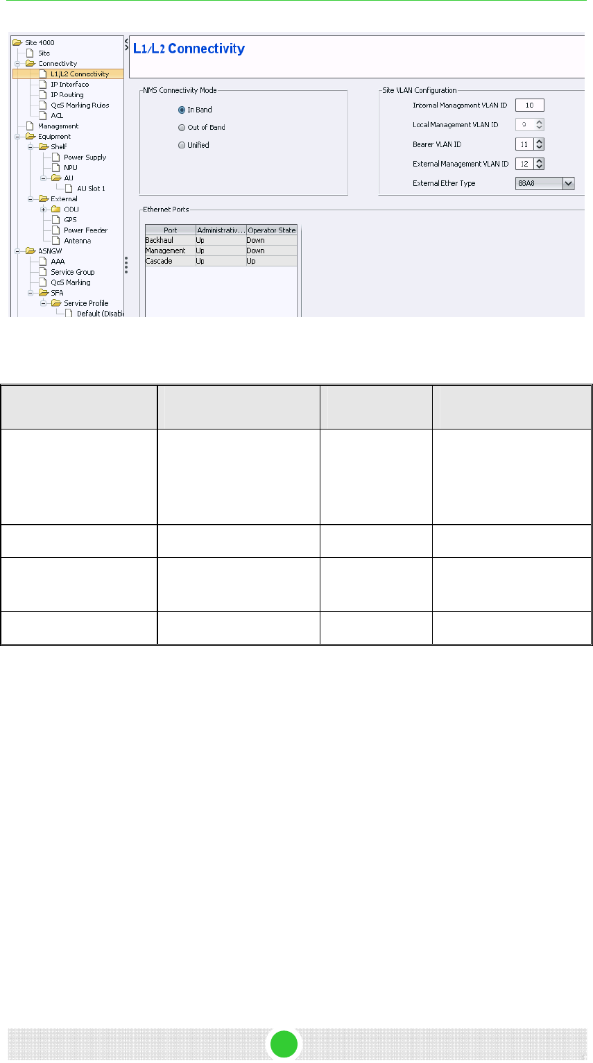
4Motion Configuration Using AlvariSTAR 4Motion Configuration
Figure 1: L1\L2 Connectivity
Table 2: L1\L2 Connectivity
Category Parameter Name Value Notes
NMS connectivity mode In band MGMT and data are
connected through the
same port and separated
by VLAN
Site VLAN configuration Bearer VLAN ID 11 Default VLAN
Site VLAN configuration External management
VLAN ID
12 Default VLAN
Ethernet ports (backhaul) Administrative port state Up
3.2.1.1 Connectivity Diagram (In-band)
The following diagram describes the In-band connectivity mode, where
VLAN is used to differentiate between the bearer and NMS IP domains on
the DATA port. The bearer VLAN is used for the bearer IP domain and the
external-management VLAN is used for NMS IP domain. The MGMT port is
used for Local Management IP interface.
4Motion - DN1031 6
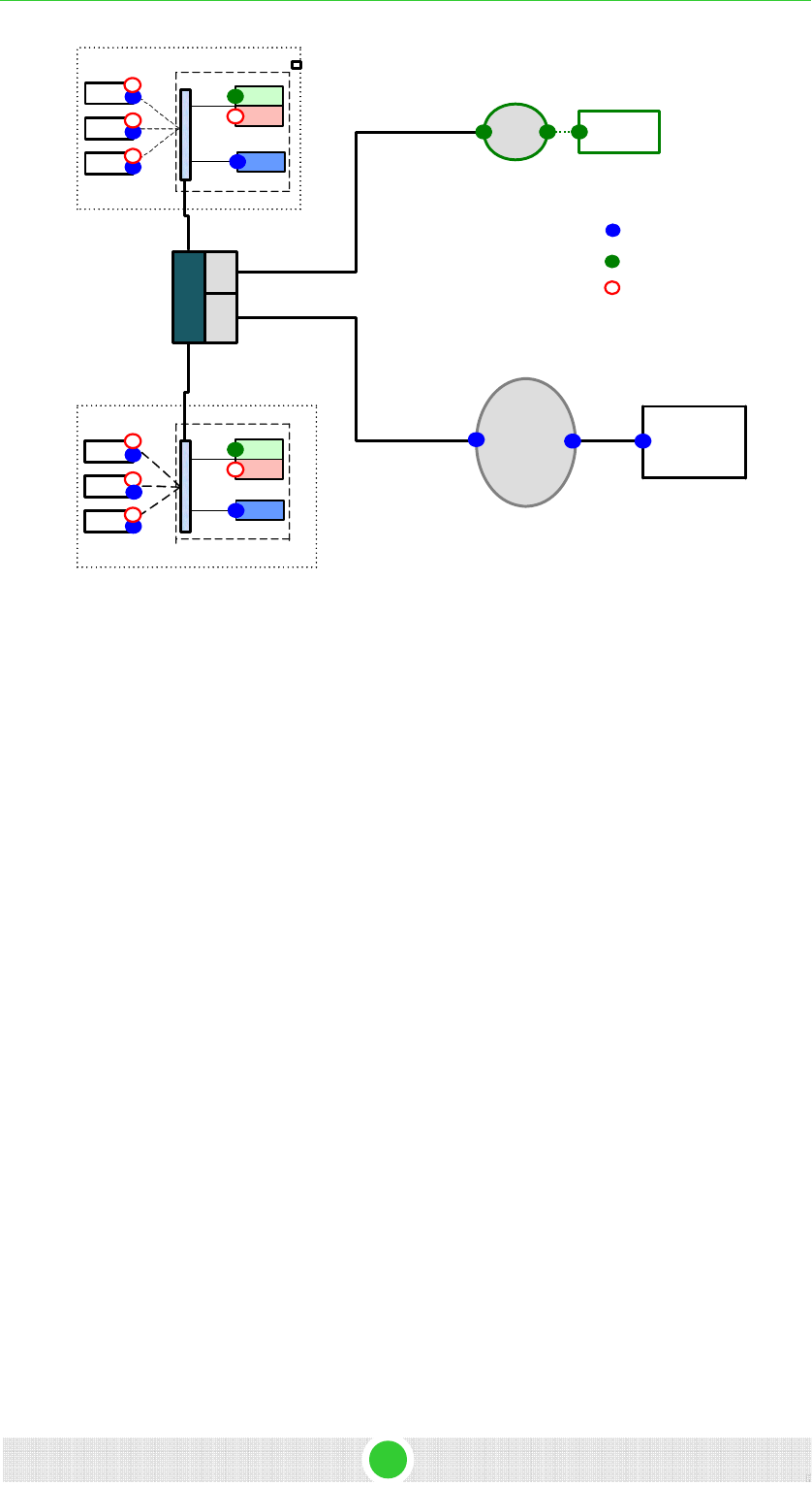
4Motion - DN1031 7
4Motion Configuration Using AlvariSTAR 4Motion Configuration
BS
BS
BS
External
ASN GW
BS
BS
BS
Cell Site 1
CSGw
card
External Layer 2Eth
Switch supporting
VLANs
VLANs
Bearer, NMS
VLANs
VLAN Bearer
VLAN NMS
NMS
IP
Network
NMS
System
NMS Master
Agent
NMS
Module
Agents
NMS
Module
Agents
IP of Backbone NMS
IP of Bearer
IP of Cell Site Internal NMS
CSGw
card
NMS Master
Agent
BS
applications
BS
applications
Bearer, NMS
Cell Site 2
Bearer
(R6/R8/R4)
IP Network
ASNGW
application
ASNGW
application
Figure 2: In-band Connectivity Mode Diagram
3.2.2 IP Interfaces Settings
Select Connectivity > IP Interface from the navigation tree.
The list contains the three available IP interfaces. The external management
interface was already configured in Section 3.1.2.
Bearer IP interface should be properly configured.
3.2.2.1 Interface Configuration
Changing the bearer or the management interfaces depend by the network
setup. To modify the IPs or any other values do the following:
1. Change the administrative status to Down.
2. Click on the Apply button.
3. Change the IP and/or any other value except for VLAN ID.
4. Click on the Apply button.
5. Change the administrative status back to UP.
6. Click on the Apply button to accept the changes.

4Motion Configuration Using AlvariSTAR 4Motion Configuration
Table 3: IP Interfaces
Parameter Name Value
Administrative status Up
IP Address External Management- 192.168.1.1
Bearer- 172.16.0.1
Local Management- 172.31.0.1
IP Subnet Mask 255.255.255.0
MTU size 1500
VLAN ID External Management -Vlan ID- 12
Bearer- Vlan ID -11
Local Management- Vlan ID-9
3.2.3 IP Routing
1. Select Connectivity > IP routing from the navigation tree.
2. The Default Route was already configured from the CLI (see Section
3.1.5)
3. If another route is needed for the specific network setup, configure it
now.
3.2.4 Management
Select Management from the navigation tree.
Add an SNMP Trap Manager as follows:
1. From the SNMP Trap Manager, click on the Add Manager button and
define all parameters as in Table 4.
2. Click on the Apply button to accept the changes.
4Motion - DN1031 8
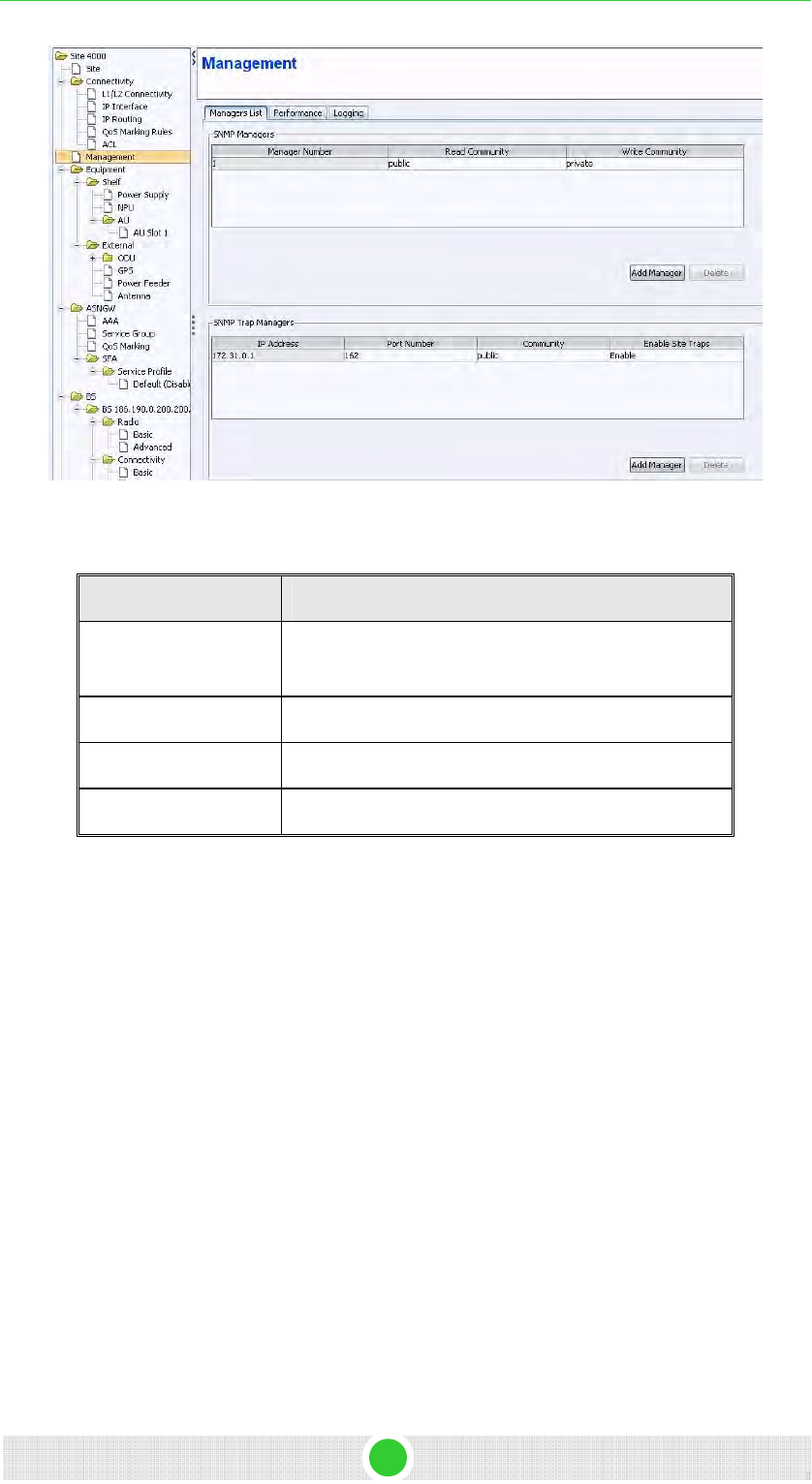
4Motion Configuration Using AlvariSTAR 4Motion Configuration
Figure 3: Management
Table 4: IP Interfaces
Parameter Name Value
IP Address External Management IP address should be
configure
Port Number 162 (default port number)
Community Public
Enable Site Traps Enable
3.2.5 AU
1. Select Equipment > Shelf > AU from the navigation tree.
2. Right-click on the AU icon and click Create.
3. AU number – select a slot number.
4. Follow Table 5 for the AU configuration.
5. Click on the Apply button to accept the changes.
A new AU will be added to the navigation tree according to the slot number
(e.g. AU Slot 1). This new screen allows the AU configuration.
4Motion - DN1031 9
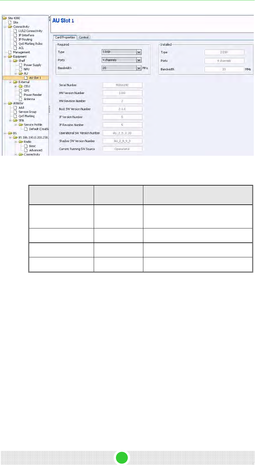
4Motion Configuration Using AlvariSTAR 4Motion Configuration
Figure 4: AU
Table 5: AU Configuration
Parameter name Value Notes
Type 3 DSP Typically used. Note that AU may support
also 4DSP
Ports 4 Channels Default for 4Motion AU cards
Bandwidth 20
AU number According to the physical slot
3.2.6 ODU
1. Select Equipment > External > ODU from the navigation tree.
2. Right-click on the ODU icon and click Create – a new ODU ID will open
(see Figure 5).
3. Select the ODU type According to the ODU installed.
4. Select the ODU number.
5. Click Apply to accept the changes.
4Motion - DN1031 10
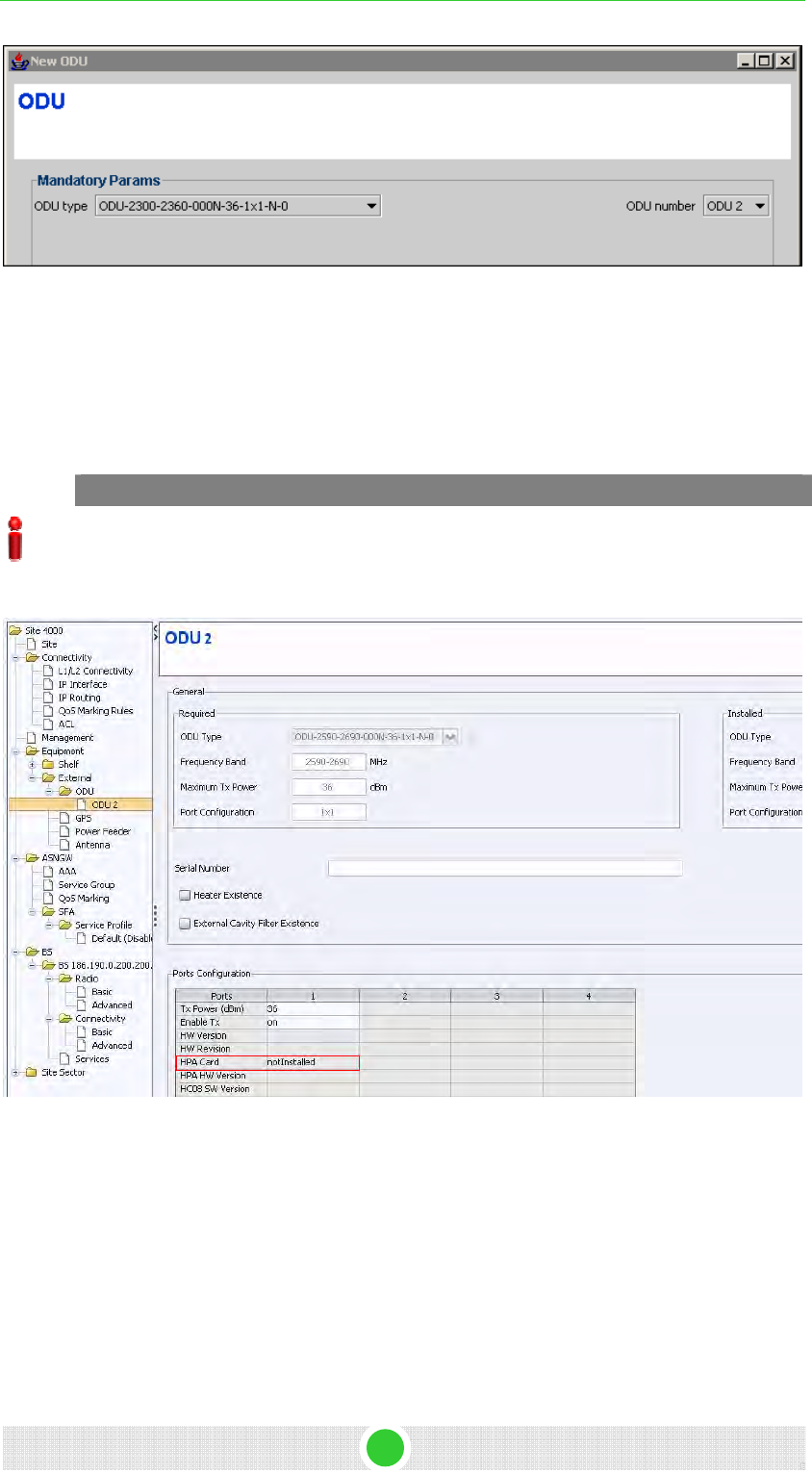
4Motion Configuration Using AlvariSTAR 4Motion Configuration
Figure 5: New ODU
A new ODU is added to the navigation tree according to the ODU
number (e.g. ODU 2). This new screen allows ODU configuration.
6. On the ODU configuration screen, click Apply to accept the default
values.
IMPORTANT
You must click Apply on the ODU configuration screen to complete the ODU creation even if
no change was made to the screen.
To verify that the ODU was added successfully, verify that the HPA Card value is Not Installed
(see Figure 6).
Figure 6: ODU
3.2.7 GPS
1. Select Equipment > External > GPS from the navigation tree.
2. Configure the GPS type according the setup. The available option is
Trimble. If no GPS is used, select None.
3. Click Apply to accept the changes.
4Motion - DN1031 11
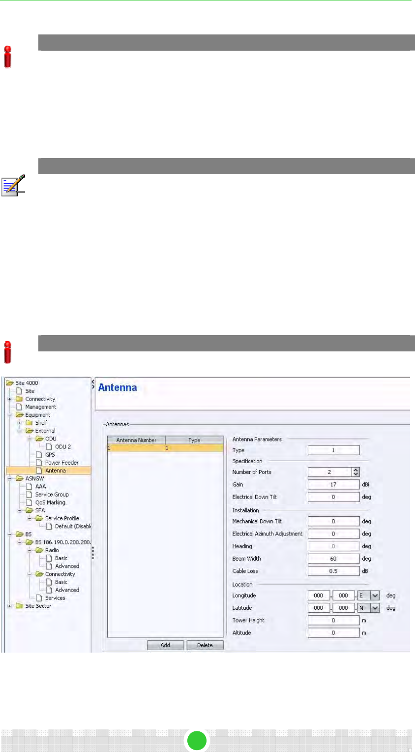
4Motion Configuration Using AlvariSTAR 4Motion Configuration
IMPORTANT
Any change in this screen requires NPU reset. You can restart the NPU after the entire
configuration is complete.
3.2.8 Antenna
This section describes the parameters needed in order to configure the
antennas settings.
NOTE
The default values presented in this document are used only to provide the minimal
requirements for establishing a connection. The numbers serve only as an example and
should be adjusted in order to receive best radio performance.
1. Select Equipment > External > Antenna from the navigation tree.
2. Click ADD to create a new antenna settings.
3. Configure the required parameters described in Figure 7.
4. Repeat the antenna configuration for each of the connected antennas.
5. Click on the Apply button to accept the changes.
IMPORTANT
Port Number and Heading are mandatory parameters.
Figure 7: Antenna
4Motion - DN1031 12
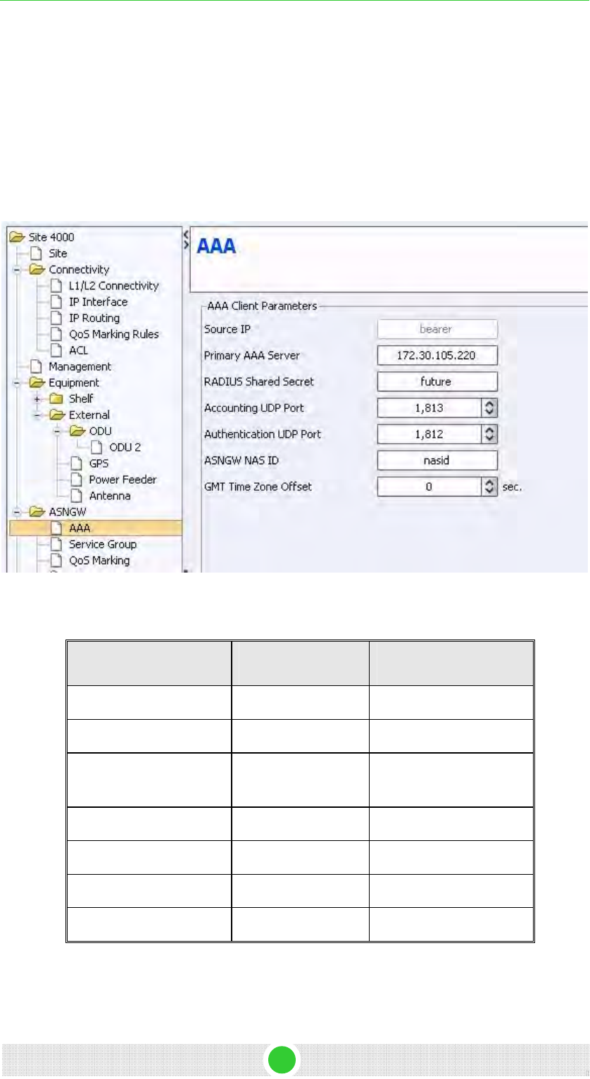
4Motion Configuration Using AlvariSTAR 4Motion Configuration
3.2.9 AAA Configuration
This configuration will create an AAA association for system authentication
and provisioning (the R3 interface).
1. Select ASNGW > AAA from the navigation tree.
2. Configure the parameters as described in Table 6.
3. Click Apply to accept the changes.
Figure 8: AAA
Table 6: AAA Client Parameters
Parameter Name Value Notes
Source IP interface bearer Read only
Primary AAA server 172.30.105.220 AAA server IP address
Radius shared secret future string - Shared secret
between AAA and ASN
Accounting UDP port 1813 Default Port no
Authentication UPD port 1812 Default Port no
ASNGW NAS ID nasid String - NAS ID
GMT time zone offset 0 Number of seconds
4Motion - DN1031 13
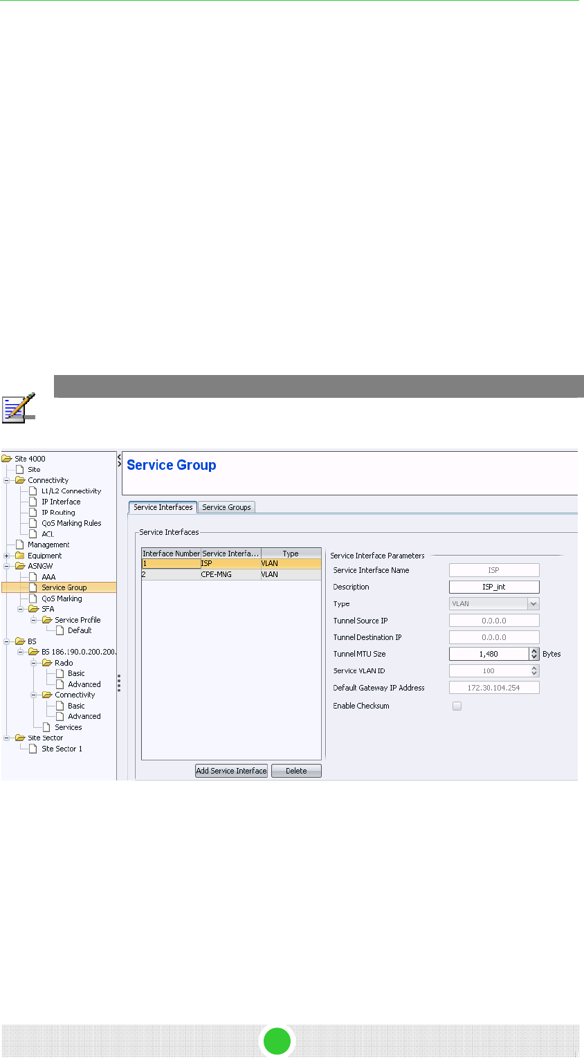
4Motion - DN1031 14
4Motion Configuration Using AlvariSTAR 4Motion Configuration
3.2.10 Service Group
This section describes the configuration of service interfaces and service
groups.
3.2.10.1 Service Interface
1. Select ASNGW > Service Group > Service Interfaces from the navigation
tree.
2. Two service interfaces must be defined: one for Data and one for
management. Add service interfaces; define the service using Figure 9,
Figure 10 and Table 7.
3. Click Apply to accept the changes.
For an example of IP-IP and Service group-IP configuration, refer to Annex
A.
NOTE
All configuration referring to Management is relevant only when working with StarACS.
Figure 9: Service Interfaces - Data
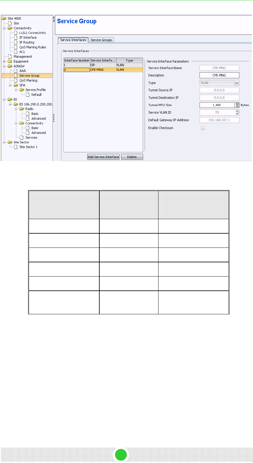
4Motion - DN1031 15
4Motion Configuration Using AlvariSTAR 4Motion Configuration
Figure 10: Service Interfaces - Management
Table 7: Service Interface
Parameter Name Value – for Data Value – for
Management
service interface Name ISP CPE_MNG
Description ISP_int CPE_MNG
type VLAN VLAN
Tunnel MTU size 1480 1480
Service VLAN ID 100 70
Default gateway IP
address
172.30.104.254 192.168.107.1
3.2.10.2 Service Group
1. Select ASNGW > Service Group > Service Groups from the navigation
tree.
2. Create two service groups: one associated with the Data service
interface and the other with the management interface. Add service
groups and follow Figure 11 to Figure 14 and Table 8.
3. Click Apply to accept the changes.
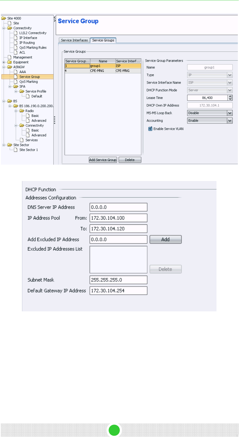
4Motion Configuration Using AlvariSTAR 4Motion Configuration
Figure 11: Service Group Parameters - Data
Figure 12: DHCP Function - Data
4Motion - DN1031 16
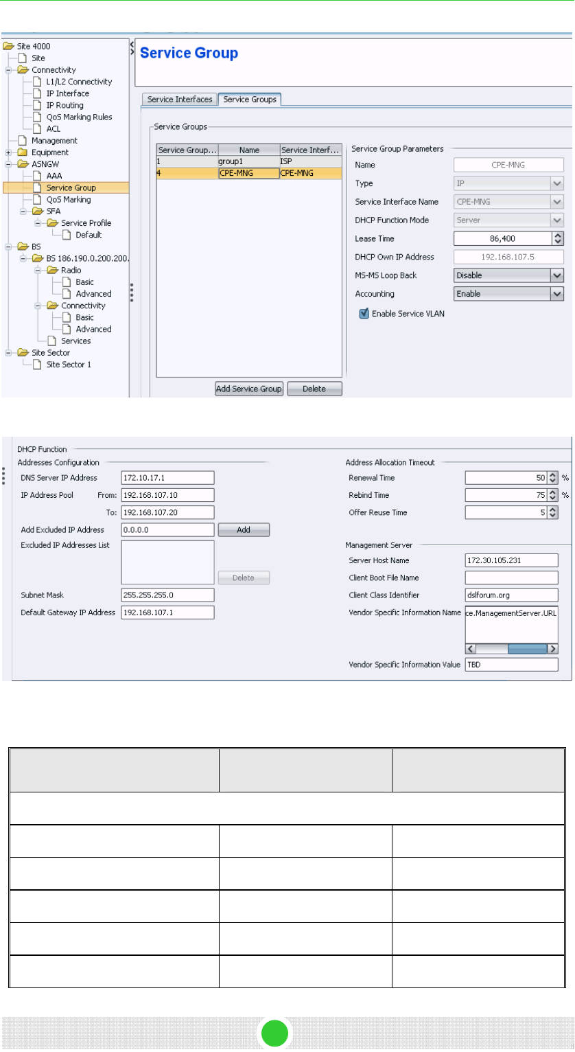
4Motion Configuration Using AlvariSTAR 4Motion Configuration
Figure 13: Service Group Parameters - Management
Figure 14: DHCP Function & Management Server - Management
Table 8: Service Group Parameters
Parameter Name Value – for Data Value – for Management
Service group parameters
Name Group1 CPE-MNG
Type IP IP
Service Interface Name ISP CPE-MNG
DHCP function Mode Server server
Lease Time 86,400 86400
4Motion - DN1031 17

4Motion - DN1031 18
4Motion Configuration Using AlvariSTAR 4Motion Configuration
Parameter Name Value – for Data Value – for Management
DHCP Own IP Address 172.30.104.1 192.168.107.5
Enable server VLAN V V
DHCP Function
DNS Server IP Address 0.0.0.0 172.10.17.1
IP address poll from 172.30.104.100 192.168.107.10
IP address poll to 172.30.104.120 192.168.107.20
Subnet mask 255.255.255.0 255.255.255.0
Default gateway IP address 172.30.104.254 192.168.107.1
Management server
Server host name 172.30.105.231- Star-ACS
IP address
Client class identifier Dslforum.org
Vendor specific information name Fill
NOTE
Dslforum.org is use only for RD2.
3.2.11 QoS Marking Rules
This configuration will create a QoS marking rule for the internal and the
external interfaces. For quick installation you can work with the default
configuration as describe in Figure 15 and Figure 16.
1. Select ASNGW > QoS Marking from the navigation tree.
2. Click Apply.
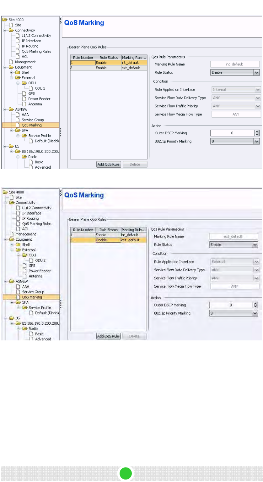
4Motion Configuration Using AlvariSTAR 4Motion Configuration
Figure 15: QoS - Internal Rule
Figure 16: QoS- External Rule
3.2.12 SFA
1. Select SFA from the navigation tree.
2. In the classification rules tab, add two classifications rules: DSCP and
DSCP6. Follow Figure 17 and Figure 18.
3. In the Layer 3 section, Enable IP TOS.
4. Define IP TOS according to Table 9.
4Motion - DN1031 19
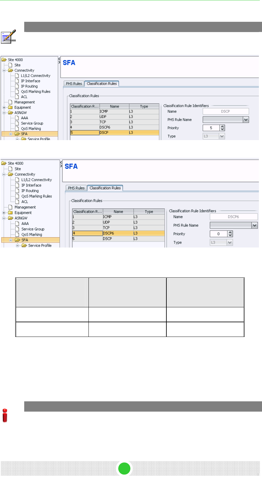
4Motion Configuration Using AlvariSTAR 4Motion Configuration
NOTE
DSCP6 is relevant only when using CPE R2.
Figure 17: SFA - DSCP
Figure 18: SFA – DSCP6
Table 9: TOS Parameters
Classification Rule
Name
TOS Range TOS Mask
DSCP From 0 to 1 63
DSCP6 From 6 to 7 0
3.2.13 Service Profile
1. Select SFA > Service Profile from the navigation tree.
A Default service profile already exists. Use the default profile or create
a new profile.
IMPORTANT
A Default service profile is used only in the Unauthenticated mode. If this mode is not used,
you need to configure a new service profile according to configuration in AAA server.
2. Bind classifier rules with 1 flow according to Table 10.
4Motion - DN1031 20
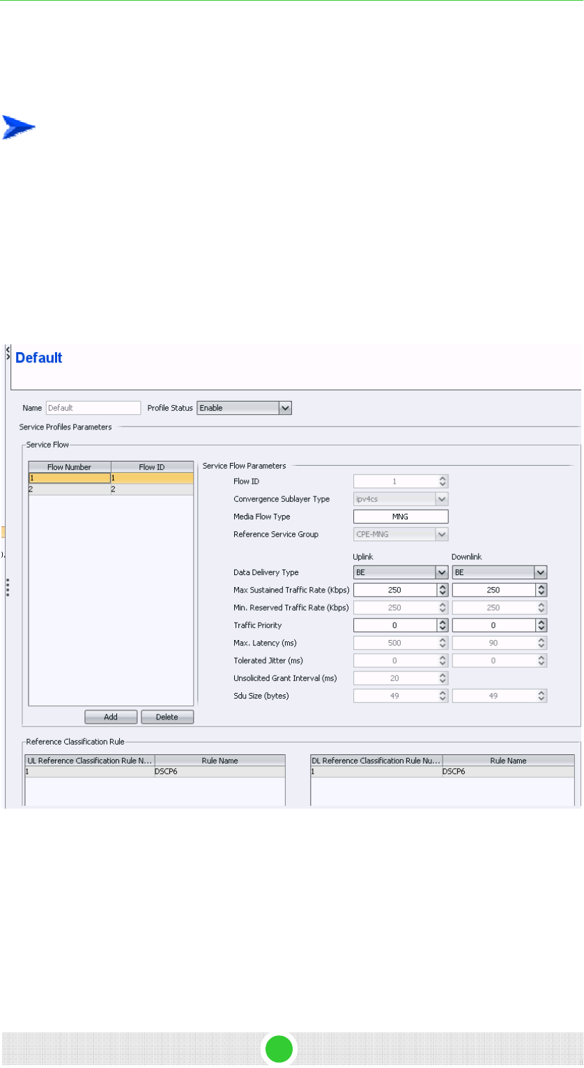
4Motion Configuration Using AlvariSTAR 4Motion Configuration
3. Change the profile status to Enable.
4. Click Apply to accept the changes.
To create a new service profile:
1. Right-click on the service profile icon and click Create.
2. Define service profile name. A new service profile is created.
3. Click Apply to accept the changes.
This newly created Service Profile will be 'empty', without a Service
Flow.
4. Add a new service flow and follow Table 10.
Figure 19: Service Profile – Management
4Motion - DN1031 21
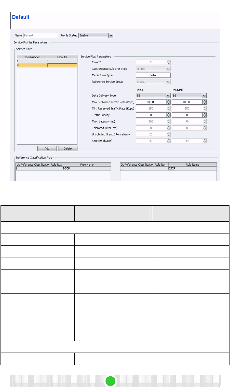
4Motion Configuration Using AlvariSTAR 4Motion Configuration
Figure 20: Service Profile – Data
Table 10: Service Profile
Parameter Name Value – for Data Value – for Management
Service flow parameters
Flow ID 2 1
Media flow type Data MNG
Reference service group Group1 CPE-MNG
Data delivery type Uplink: BE
Downlink: BE
Uplink: BE
Downlink: BE
Max sustained traffic rate (kbps) Uplink: 512
Downlink: 512
Uplink: 250
Downlink: 250
traffic priority Uplink: 0
Downlink: 0
Uplink: 0
Downlink: 0
Reference Classifier Rule
UL DSCP DSCP6
4Motion - DN1031 22
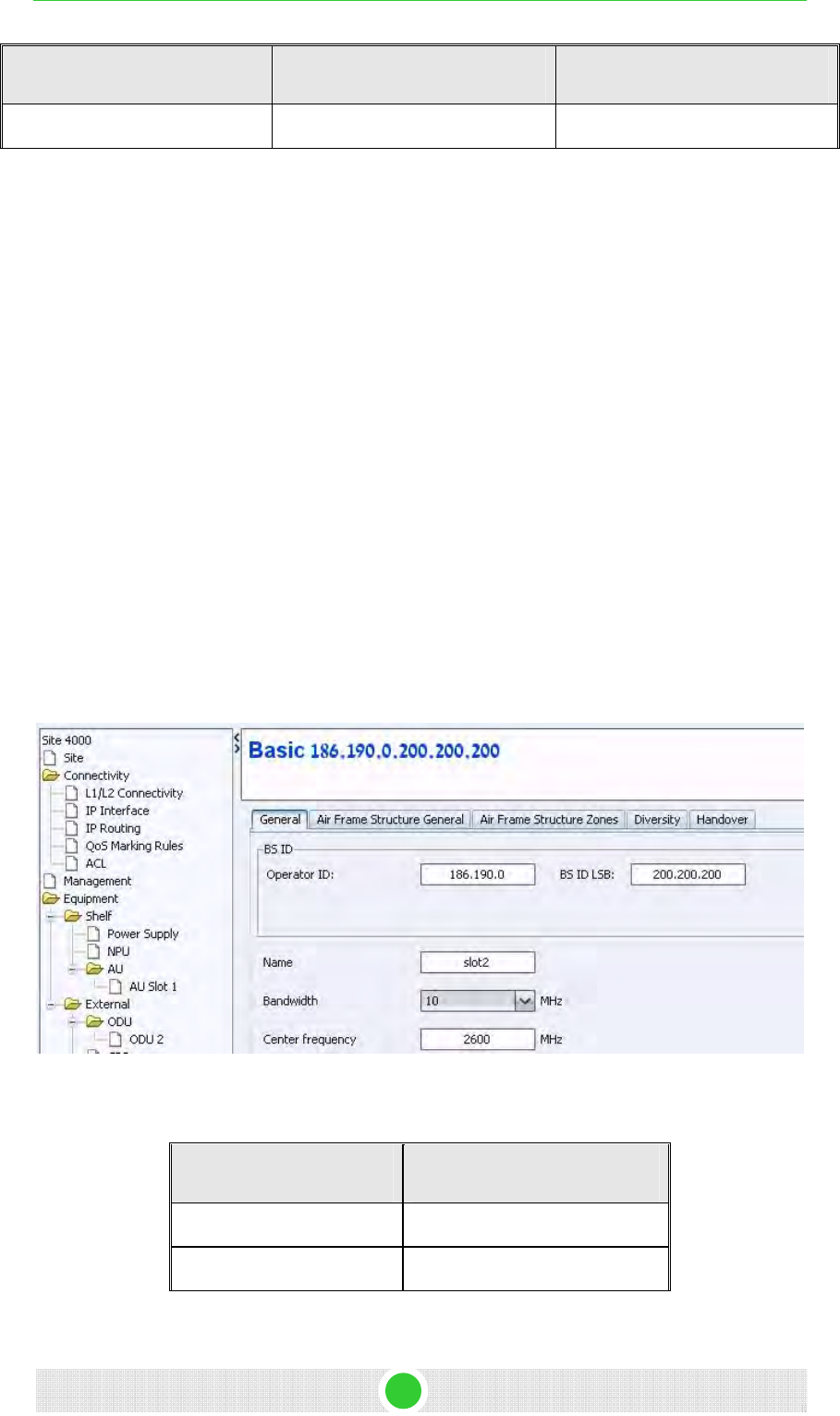
4Motion - DN1031 23
4Motion Configuration Using AlvariSTAR 4Motion Configuration
Parameter Name Value – for Data Value – for Management
DL DSCP DSCP6
3.2.14 BS
1. In the navigation tree, right click on BS and click Create.
2. Define the following:
¾ BS LSB- This value should be unique in the network. For example,
1.2.3 (Driven from the value 01.02.03 (HEX) which is 66051 (DEC)
¾ Operator ID- populated with the last operator ID in the DB. Should
be the same for all BSs of a specific operator.
3. Click Apply to accept the changes.
3.2.14.1 BS Radio Configuration
3.2.14.1.1 Basic
Select BS > BS ID > Radio > Basic from the navigation tree.
3.2.14.1.1.1 General
Configure the parameters according to Table 11.
Figure 21: RC General
Table 11: RC General
Parameter Name Value
Name Slot2
Bandwidth 10 MHz
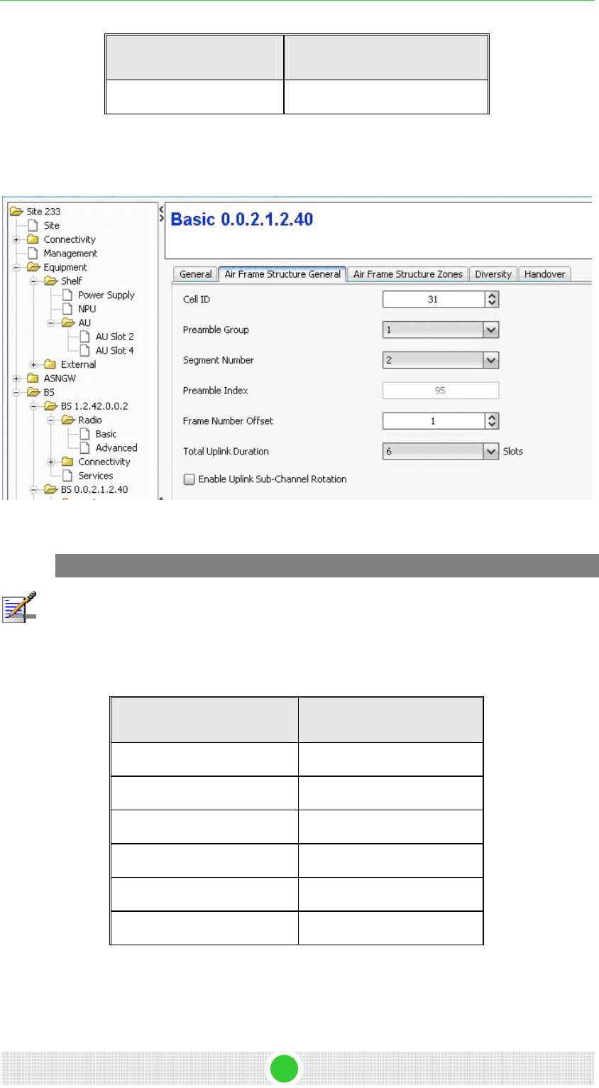
4Motion - DN1031 24
4Motion Configuration Using AlvariSTAR 4Motion Configuration
Parameter Name Value
Central frequency 2600.0
3.2.14.1.1.2 Air Frame Structure General
Configure the parameters according to Table 12.
Figure 22: RC AFSG
NOTE
Preamble Index formula: segment X 32 + Cell ID
Segment- available values: 0-2
Cell ID- available values: 0-31
Please notice that if the value of Preamble Index = 0, It means that this AU is down.
Table 12: RC AFSG
Parameter Name Value
Cell ID 31
Preamble group 1
Segment number 2
Preamble index 2*32+31 = 95
Frame number offset 0
Total uplink duration 6
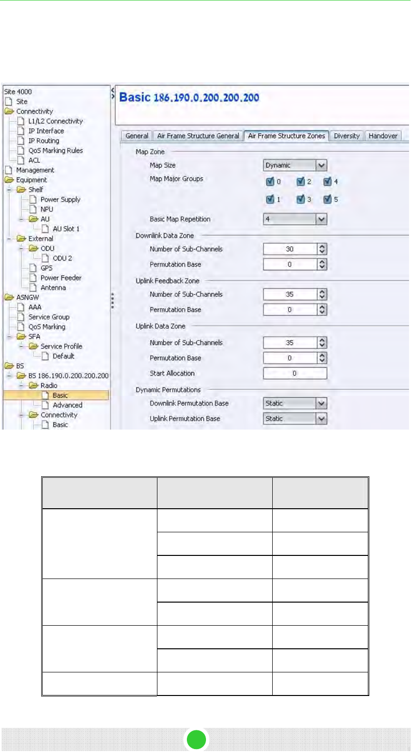
4Motion Configuration Using AlvariSTAR 4Motion Configuration
3.2.14.1.1.3 Air Frame Structure Zone
Configure the parameters from Table 13. The following parameters are for
10 MHz bandwidth.
Figure 23: RC AFSZ
Table 13: RC AFSZ
Category Parameter Name Value
Map size Dynamic
Map major groups mark ALL (0-5)
Map Zone
Basic Map repetition 4
Num of sub channels 30 Downlink data zone
Permutation base 0
Num of sub channels 35 Uplink Feedback zone
Permutation base 0
Uplink Data Zone Num of sub channels 35
4Motion - DN1031 25
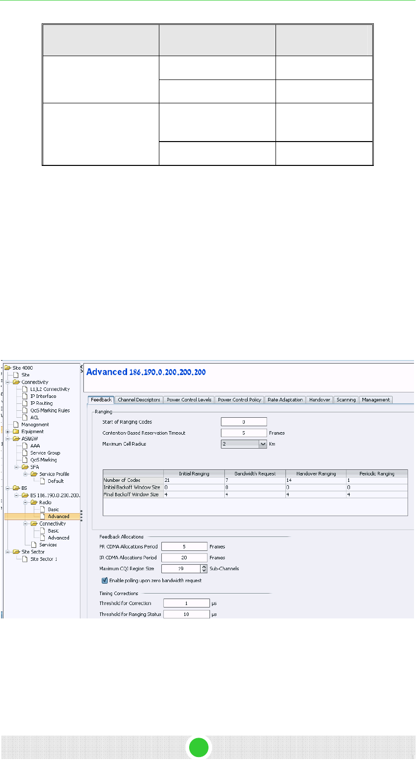
4Motion - DN1031 26
4Motion Configuration Using AlvariSTAR 4Motion Configuration
Category Parameter Name Value
Permutation base 0
Start allocation 0
Downlink Permutation
base
Static Dynamic permutation
Uplink Permutation base Static
3.2.14.1.1.4 Diversity
Use none at this point, it is not mandatory for first link.
3.2.14.1.2 Advanced
1. Select BS > BS ID > Radio > Advance from the navigation tree.
2. Configure the parameters according to the screen captures below.
3. After making all the required changes, click Apply to accept the
changes.
3.2.14.1.2.1 Feedback
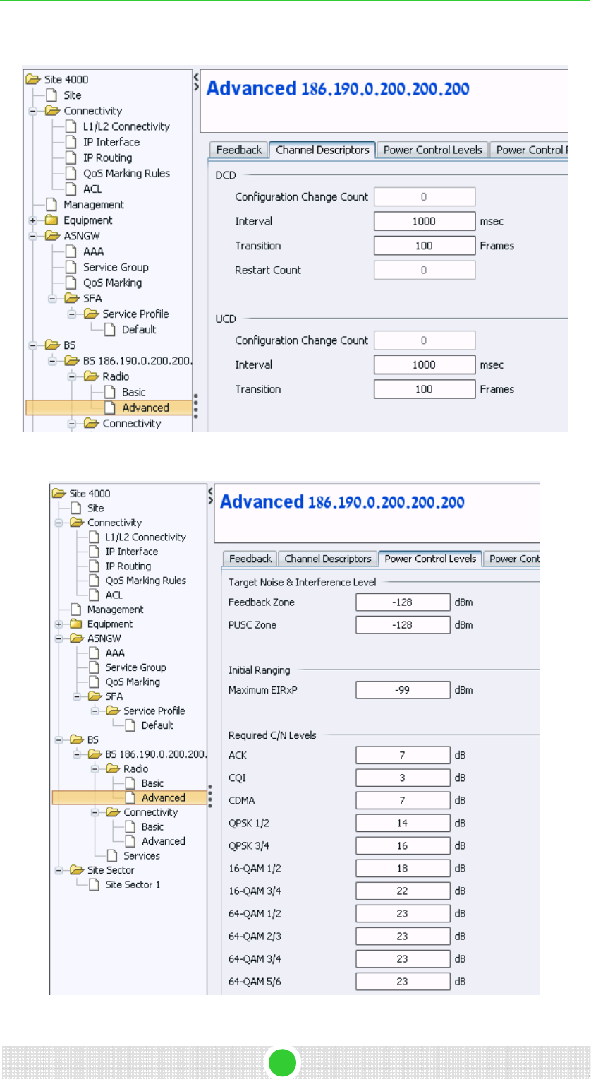
4Motion Configuration Using AlvariSTAR 4Motion Configuration
3.2.14.1.2.2 Channel Description
3.2.14.1.2.3 Power Control Levels
4Motion - DN1031 27
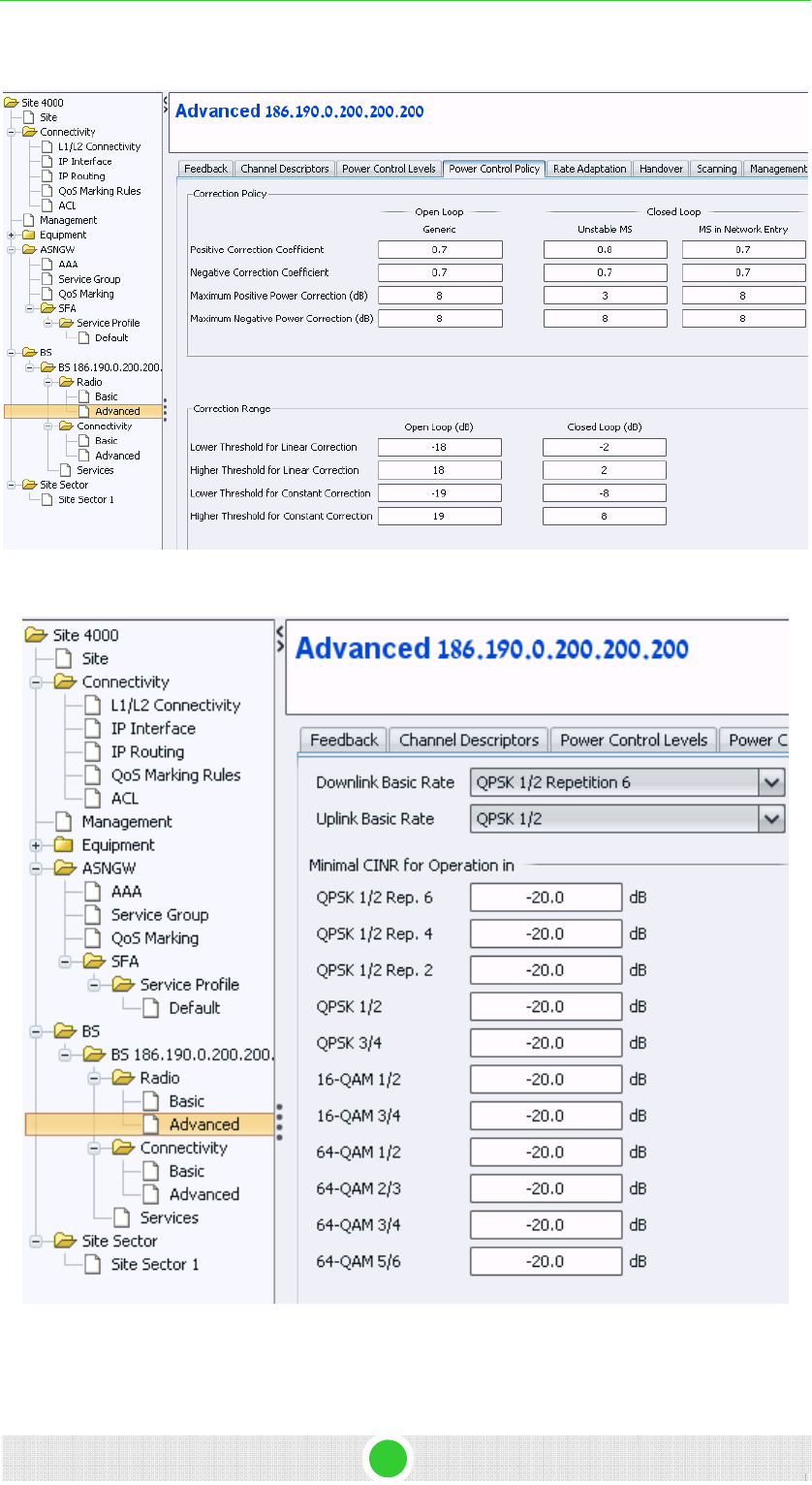
4Motion Configuration Using AlvariSTAR 4Motion Configuration
3.2.14.1.2.4 Power Control Policy
3.2.14.1.2.5 Rate Adaptation
4Motion - DN1031 28
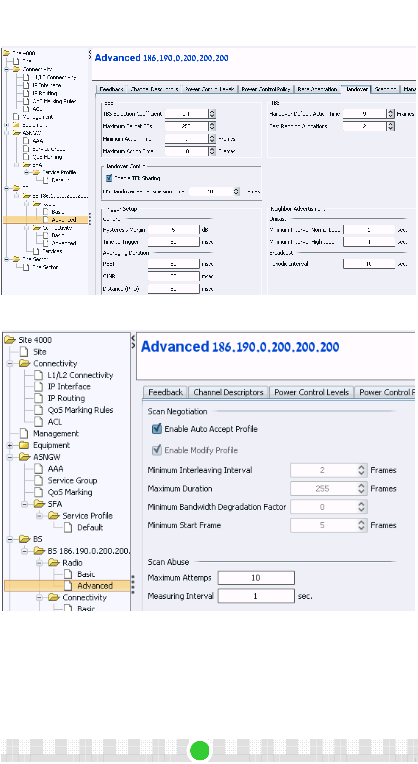
4Motion Configuration Using AlvariSTAR 4Motion Configuration
3.2.14.1.2.6 Handover
3.2.14.1.2.7 Scanning
4Motion - DN1031 29
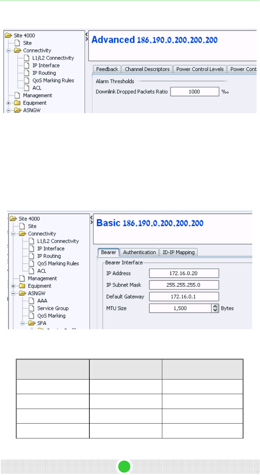
4Motion - DN1031 30
4Motion Configuration Using AlvariSTAR 4Motion Configuration
3.2.14.1.2.8 Management
3.2.14.2 Connectivity
asic 3.2.14.2.1 B
Select BS > BS ID > Connectivity > Basic from the navigation tree.
3.2.14.2.1.1 Bearer
1. Configure the bearer parameters according to Table 14.
2. Click Apply to accept the changes.
Figure 24: Bearer
Table 14: Bearer
Category Parameter Name Value
Bearer Connectivity IP Address 172.16.0.20
Bearer Connectivity IP sub mask 255.255.255.0
Bearer Connectivity Default gateway 172.16.0.1
Bearer Connectivity MTU size 1500
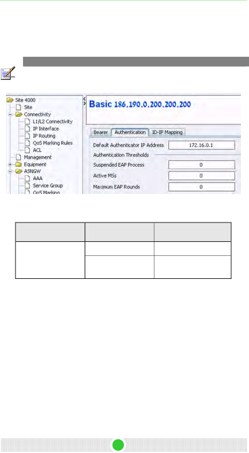
4Motion - DN1031 31
4Motion Configuration Using AlvariSTAR 4Motion Configuration
3.2.14.2.1.2 Authentication
1. Configure the authentication parameters according to Table 18.
2. Click Apply to accept the changes.
NOTE
Active MSs counts the number of connected MSs. Therefore, increase the threshold value,
otherwise an alarm will be generated for exceeded number of MSs as soon as an MS
connects.
Figure 25: Authentication
Table 15: Authentication
Category Parameter Name Value
Default Authenticator IP 172.16.0.1 Default Authenticator IP
Active MSs Number of MSs that will
connect this BS
3.2.14.2.2 Advanced
1. Select BS > BS ID > Connectivity > Advanced from the navigation tree.
2. Define one rule according to Figure 26.
3. Click Apply to accept all changes.
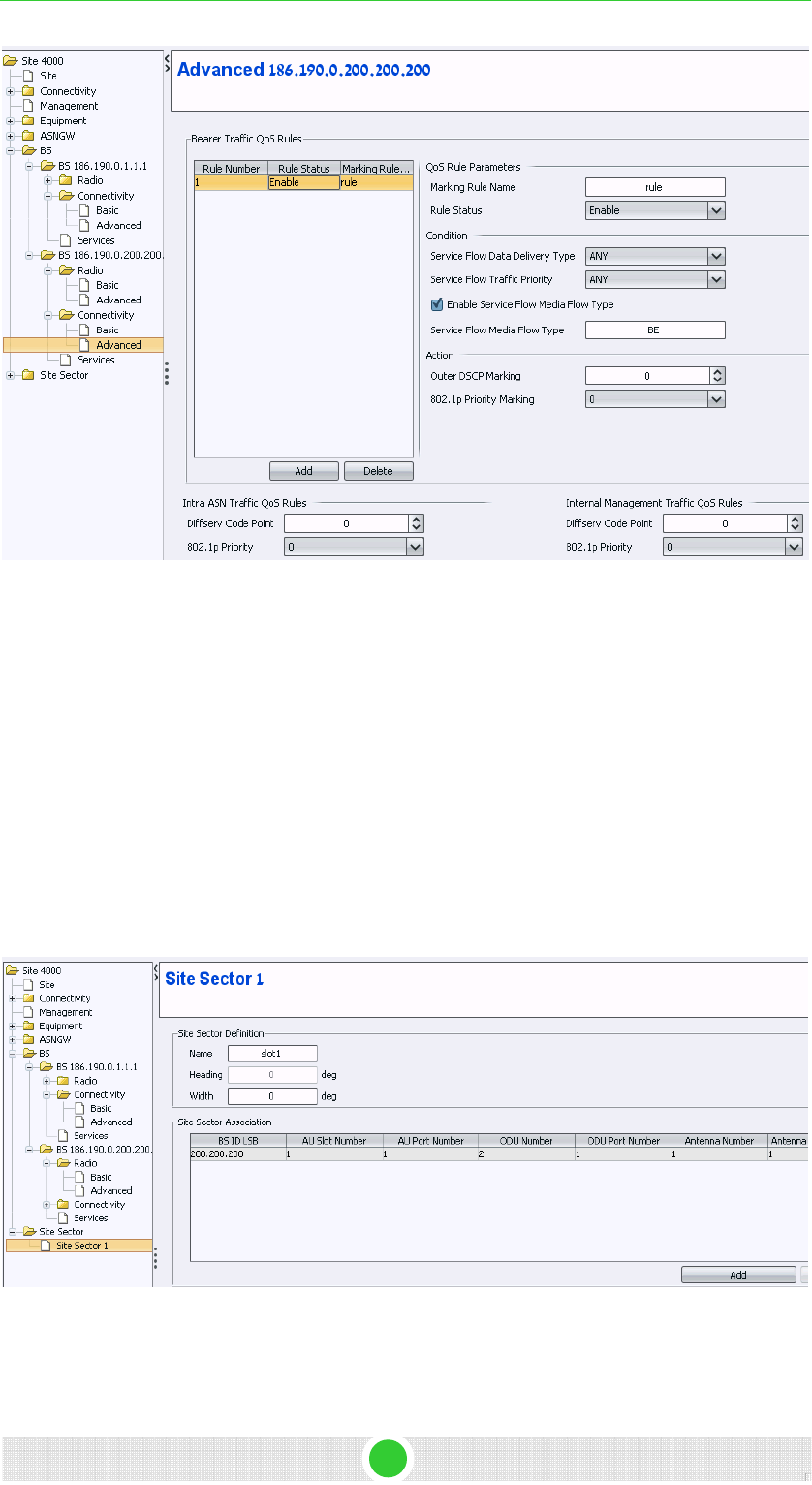
4Motion Configuration Using AlvariSTAR 4Motion Configuration
Figure 26: Connectivity - Advanced
3.2.15 Site Sector
1. In the navigation tree, right-click on Site Sector and create new site
sector.
2. Select the site sector number.
3. Click Apply to accept the change. A new Site Sector is created.
4. In the new site sector window, define the parameters according to
Figure 27.
5. Click Apply to accept the changes.
Figure 27: Site Sector
4Motion - DN1031 32

4Motion Configuration Using AlvariSTAR 4Motion Configuration
3.3 Apply All Changes
For all the changes to take effect, you need to restart the NPU via
AlvariSTAR.
NOTE
The NPU restart must be performed only via AlvariSTAR, otherwise the last changes will not
be saved.
4Motion - DN1031 33
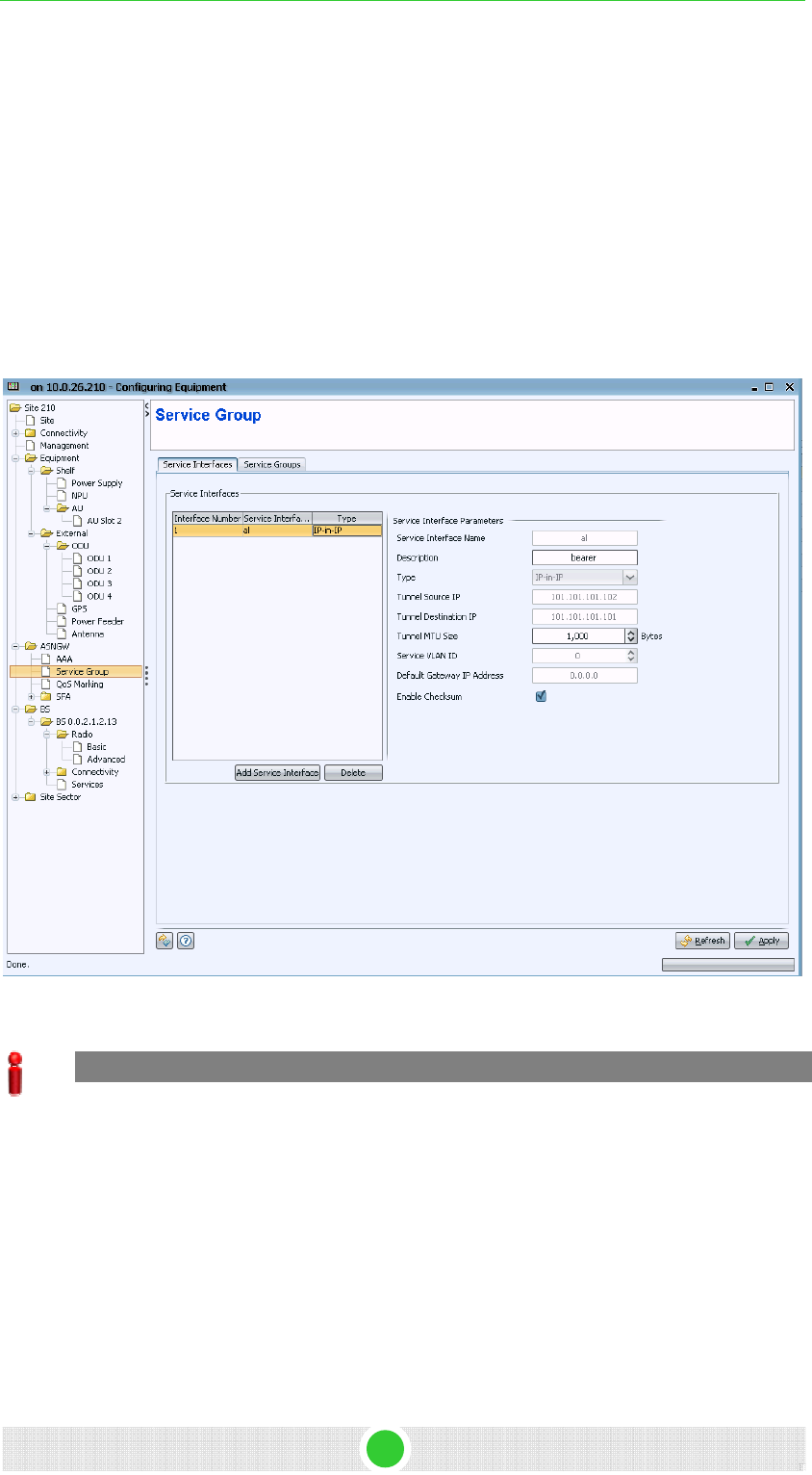
4Motion Configuration Using AlvariSTAR 4Motion Configuration
Annex A. CPEs Support
This example describes the following:
1. configuration of SI, SG, SP, SF for all other CPEs (not R2)
2. Working with IP mode (thus far, VLAN mode was described)
A.1. Service Interface
Service interface configuration
Type IP-in IP is used
A.2. service Group
IMPORTANT
It is important to verify that the 'Vendor Class Identifier' parameter is configured according to
the value of Option 60 located in the DHCP-discover message sent by the CPE.
For WCM and RGW 'Vendor Class Identifier'= MSFT 5.0
4Motion - DN1031 34
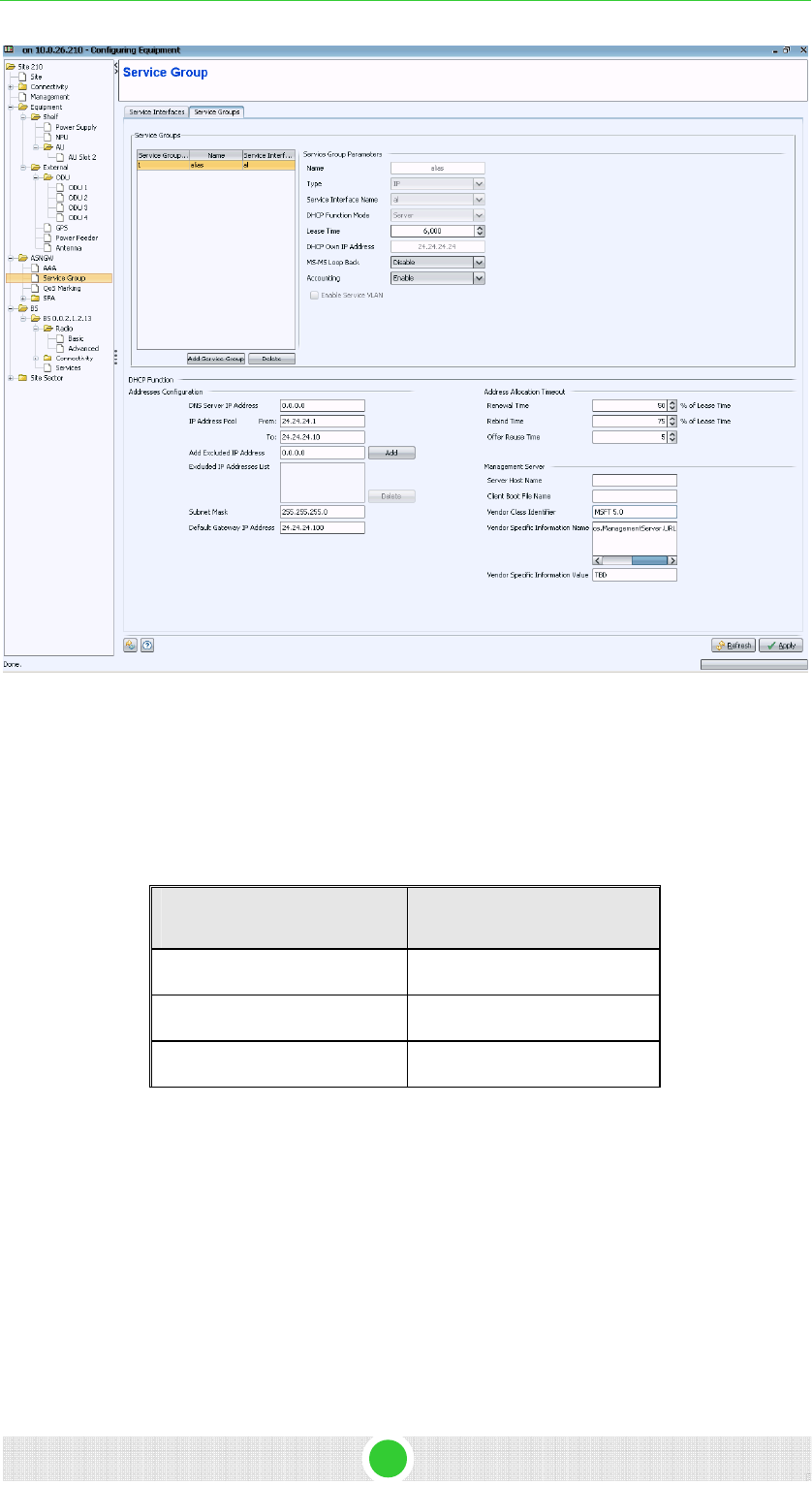
4Motion Configuration Using AlvariSTAR 4Motion Configuration
Figure 28: Service Group
A.3. SFA- Classification Rules
Configure three classifier rules with the IP protocol value as describe in the
following table:
Classifier Name IP Protocol Value
TCP 6
UDP 17
ICMP 1
4Motion - DN1031 35
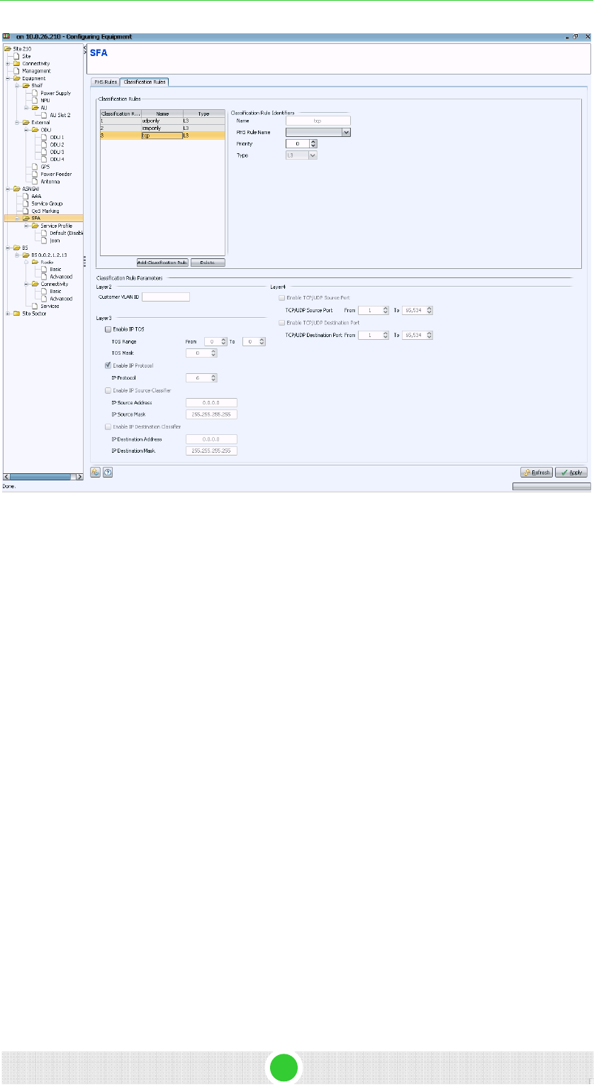
4Motion Configuration Using AlvariSTAR 4Motion Configuration
Figure 29: SFA
A.4. Service
Create a new service profile with the following flow:
1. One service flow with the service group describe in A.2.
2. Define three classifiers for downlink and three for uplink as described in
A.3.
4Motion - DN1031 36
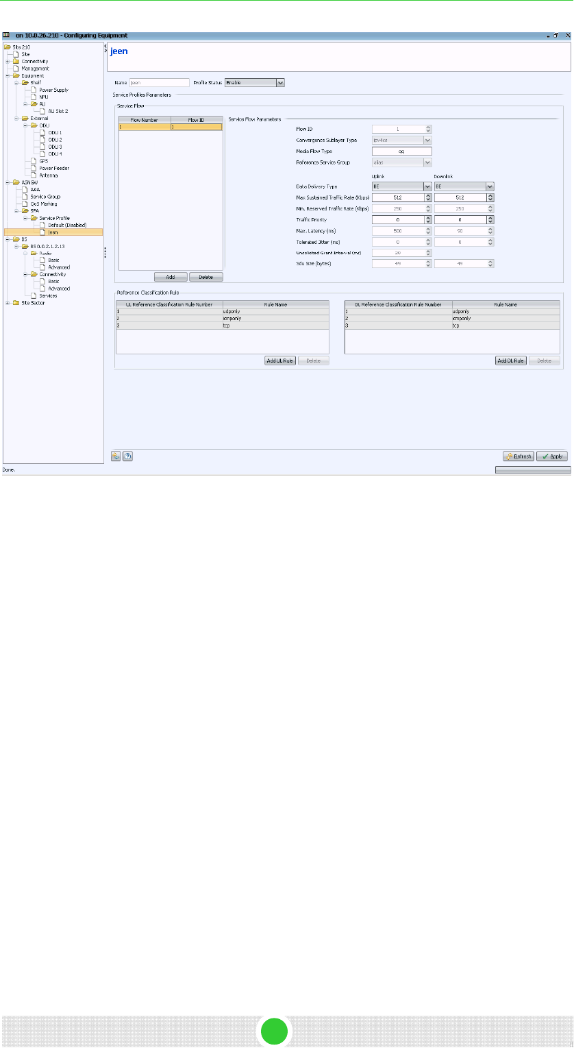
4Motion Configuration Using AlvariSTAR 4Motion Configuration
4Motion - DN1031 37
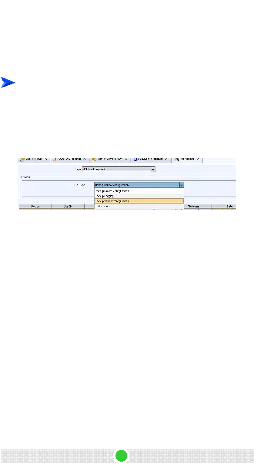
4Motion Configuration Using AlvariSTAR 4Motion Configuration
Annex B. Uploading the Vendor Configuration
File
Uploading vendor configuration file is mandatory after every software
upgrade.
To upload the vendor configuration file:
1. Take the vendor_startup.xml file and generate a .gz file (zip file) from it.
2. From the navigation tree, select File Manager and import
vendor_startup.xml.gz file, by clicking Import > Select File > Import.
3. In the File Manager, select File Type 'Backup Vendor Configuration' and
click on the Retrieve button.
The vendor_startup.xml.gz file will is displayed.
4. Click on the file.
5. Click on the Restore button at the right. The Restore Configuration
window is displayed.
6. In the Restore Configuration window, click on Add.
7. Select your site and click Select.
8. Click on Run. The downloading process begins.
9. When the process completed message is displayed, close the window.
4Motion - DN1031 38
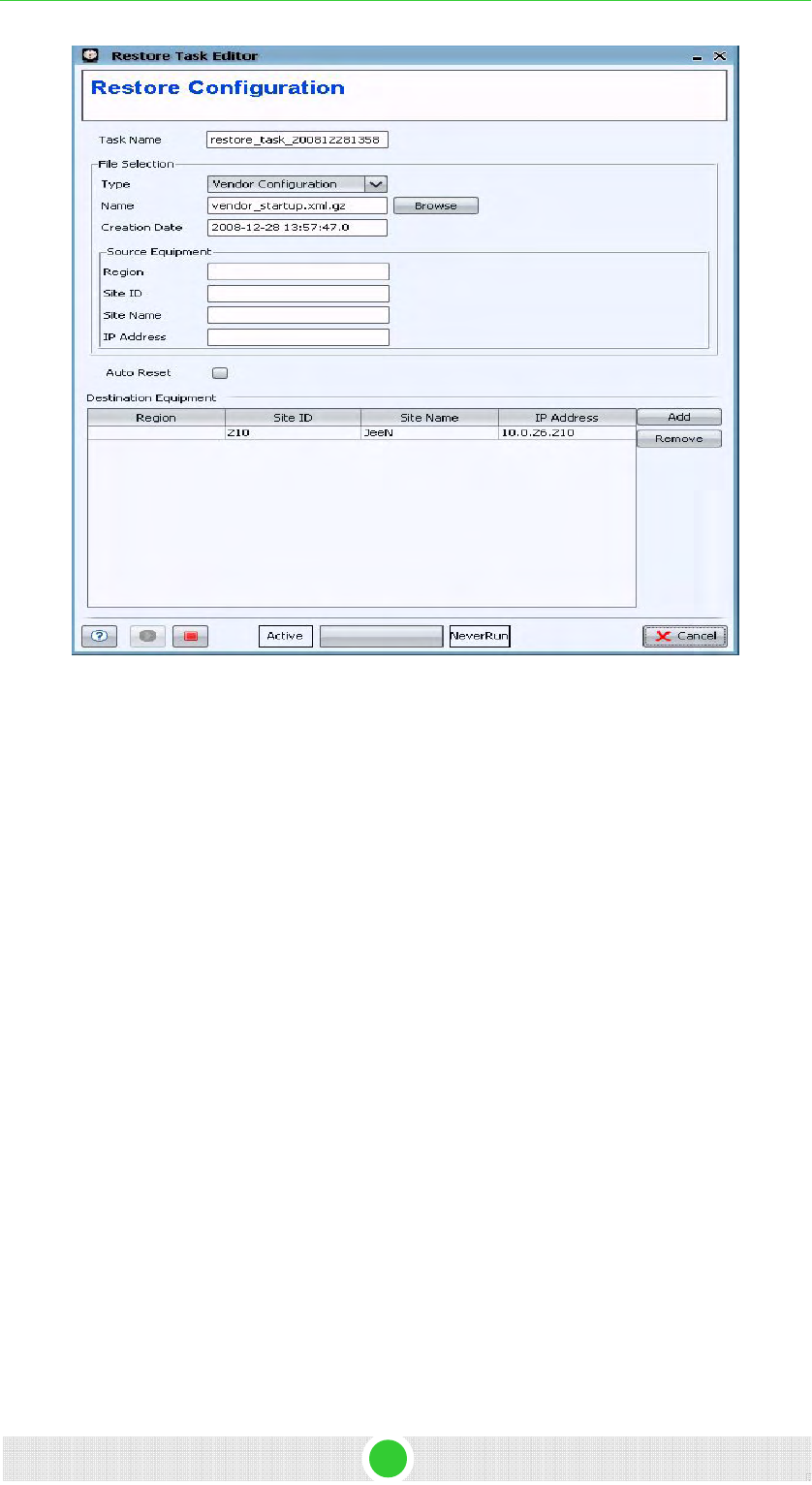
4Motion Configuration Using AlvariSTAR 4Motion Configuration
Figure 30: Restore Configuration
10. Perform NPU reset. The NPU will start up with the configured vendor
parameters (including asnif and csnif).
4Motion - DN1031 39

Glossary

Glossary
4Motion 911 System Manual
10Base-T An Ethernet cabling standard where data is transmitted in baseband spectrum of a
twisted pair cable (i.e. Cat 3 or better, Cat 5 in most networks) with data rate of 10
Mbps. (10 for 10Mbps, Base for baseband, T for twisted pair). 10Base-T
implementation uses star topology.
100Base-T An Ethernet cabling standard where data is transmitted in baseband spectrum of a
twisted pair cable (i.e. Cat 5 or better), with data rate of 100 Mbps. 100Base-T
implementation uses star topology. 100Base-T is also known as Fast Ethernet.
1000Base-T An Ethernet cabling standard where data is transmitted in baseband spectrum of a
twisted pair cable (Cat 5E or better), with data rate of 1000 Mbps. 1000Base-T
implementation uses star topology. 1000Base-T is also known as Gigabit Ethernet.
3G Third generation wireless service, designed to provide high data speeds, always-on
data access, and greater voice capacity..
AAA Authentication, Authorization, and Accounting (pronounced "triple a."). A system (or
several systems) that controls what resources users have access to, and keeps
track of the activity of users over the network.
AAS Adaptive Antenna System, also called Advanced Antenna System, is a technology to
enable the network operators to increase the wireless network capacity. In addition,
adaptive antenna systems offer the potential of increased spectrum efficiency,
extended range of coverage and higher rate of frequency reuse. Adaptive antenna
systems consist of multiple antenna elements at the transmitting and/or receiving
side of the communication link, whose signals are processed adaptively in order to
exploit the spatial dimension of the mobile radio channel. Depending on whether the
processing is performed at the transmitter, receiver, or both ends of the
communication link, the adaptive antenna technique is defined as multiple-input
single-output (MISO), single-input multiple-output (SIMO), or multiple-input
multiple-output (MIMO).
ACL Access Control List. A filtering mechanism used by many access IP routers that
controls which traffic may be received or transmitted on an interface or port.
AISG Antenna Interface Standards Group. The objective of the group is to facilitate the
introduction of base station antennas with remotely adjustable tilt by agreeing open
standards for the associated data transmission system.
ANSI American National Standards Institute. A voluntary organization composed of
corporate, government, and other members that coordinates standards-related
activities, approves U.S. national standards, and develops positions for the United
States in international standards organizations.
ARP Address Resolution Protocol. Internet protocol used to map an IP address to a MAC
address. Defined in RFC 826.
ARQ Automatic Repeat reQuest. A communication technique in which the receiving
device detects errors and requests retransmissions.
ASCII American Standard Code for Information Interchange. A code for representing
English characters as numbers, with each letter assigned a number from 0 to 127.

Glossary
4Motion 912 System Manual
ASN Access Service Network. An ASN is defined as a complete set of network functions
needed to provide radio access to a WiMAX subscriber. An ASN is comprised of
network elements such as one or more Base Stations (BS) and one or more ASN
gateways (ASN-GW). An ASN may be shared by more than one Connectivity
Service Network (CSN).
ASN-GW Access Service Network Gateway. The ASN-GW is a network entity that acts as a
gateway between the ASN and CSN. The ASN functions hosted in an ASN-GW may
be viewed as consisting of two groups - the decision point (DP) that provides control
functionality and enforcement point (EP) that provides bearer transport.
ASP Application Service Provider. A third-party entity that manages and distributes
software-based services and solutions to customers across a wide area network
from a central data center.
AU Access Unit
AVU Air Ventilation Unit
AWG An electronics industry acronym for American Wire Gauge. AWG is a measure of the
thickness of copper, aluminum and other wiring.
AWGN Additive White Gaussian Noise. Also known as WGN. Constant spectral energy at
all frequencies with a probability histogram that follows a Gaussian bell shaped
curve.
BE Best Effort. Service supporting applications with no strict rate or delay requirements.
BS Base Station. The WiMAX BS is an entity that implements the WiMAX MAC and PHY
in compliance with the IEEE 802.16e standard. A BS operates on one frequency
assignment, and incorporates scheduler functions for uplink and downlink resources.
BTS Base Transceiver Station. A wireless network element that provides the radio
interface of the network. The BTS comprises the radio transmission and reception
devices, and also manages the signal processing related to the air interface.
BW Bandwidth
BWA Broadband Wireless Access
CALEA The Communications Assistance for Law Enforcement Act is a United States
wiretapping law passed in 1994. In its own words, the purpose of CALEA is: To
amend title 18, United States Code, to make clear a telecommunications carrier's
duty to cooperate in the interception of communications for Law Enforcement
purposes, and for other purposes. CALEA was intended to preserve the ability of law
enforcement agencies to conduct electronic surveillance by requiring that
telecommunications carriers and manufacturers of telecommunications equipment
modify and design their equipment, facilities, and services to ensure that they have
the necessary surveillance capabilities.

Glossary
4Motion 913 System Manual
CDMA Code Division Multiple Access is a second generation (2G) cellular technology
defined by Qualcomm in IS-95 and IS-2000. A coding scheme, used as a modulation
technique, in which multiple channels are independently coded for transmission over
a single wideband channel. In some communication systems, CDMA is used as an
access method that permits carriers from different stations to use the same
transmission equipment by using a wider bandwidth than the individual carriers. On
reception, each carrier can be distinguished from the others by means of a specific
modulation code, thereby allowing for the reception of signals that were originally
overlapping in frequency and time. Thus, several transmissions can occur
simultaneously within the same bandwidth, with the mutual interference reduced by
the degree of orthogonality of the unique codes used in each transmission.
CE The CE-marking is a European Union regulatory community sign. It symbolizes the
compliance of the product with all essential requirements relating to safety, public
health, consumer protection.
CINR Carrier-to-Interference plus Noise Ratio (expressed in dB)
CIR Committed Information Rate. The rate (in bits per second) at which a network
guarantees to transfer information under normal conditions, averaged over a
minimum increment of time.
CLI Command Line Interface. A user interface that accepts typed commands to instruct
the managed device on the task to perform.
cPCI Compact Peripheral Component Interface. a standard for computer backplane
architecture and peripheral integration, defined and developed by the peripheral
component interconnect (PCI) industrial computers manufacturers group (PICMG).
Designed to provide rugged, high-density systems.
CPU Central Processing Unit.
CQI Channel Quality Information
CS Convergence Sublayer. Particular protocols that are responsible for gathering and
formatting higher layer information so it can be processed by the lower layers.
CSMA/CD Carrier Sense Multiple Access with Collision Detection. Media-access mechanisms
wherein devices ready to transmit data first check the channel for a carrier. If no
carrier is sensed for a specific period of time, a device can transmit. If two devices
transmit at once, a collision occurs and is detected by all colliding devices. This
collision subsequently delays retransmissions from those devices for some random
length of time. Ethernet and IEEE 802.3 use CSMA/CD access.
CSN Connectivity Service Network. A CSN is defined as a set of network functions that
provide IP connectivity services to WiMAX subscribers and all the IP core network
functions. A CSN is comprised of network elements such as routers, proxy/servers,
user databases, and inter-working gateway devices.
CTC Convolutional Turbo Code is a type of turbo codes with some of the convolutional
schemes used. For its high-performance error correction nature, CTC is the iterative
decoding scheme of choice as evidenced by their wide adoption in standards bodies.
DCD Downlink Channel Descriptor.

Glossary
4Motion 914 System Manual
DHCP Dynamic Host Configuration Protocol. A protocol for dynamically assigning IP
addresses from a pre-defined list to nodes on a network. Using DHCP to manage IP
addresses simplifies client configuration and efficiently utilizes IP addresses.
DL Down Link
DSCP Differentiated Service Code Point, AKA DiffServ: An alternate use for the ToS byte in
IP packets. Six bits of this byte are being reallocated for use as the DSCP field
where each DSCP specifies a particular per-hop behavior that is applied to the
packet.
DNS Domain Naming System. A system that stores information about hostnames and
domain names. DNS provides an IP address for each hostname, and lists the e-mail
exchange servers accepting e-mail addresses for each domain.
DoS Denial of Service
DSL Digital Subscriber Line. A technology that exploits unused frequencies on copper
telephone lines to transmit traffic typically at multi-megabit speeds. DSL can allow
voice and high-speed data to be sent simultaneously over the same line. Because
the service is 'always available,' end-users don't need to dial in or wait for call set-up.
EAP Extensible Authentication Protocol, A protocol used between a user station and an
authenticator or authentication server. It acts as a transport for authentication
methods or types. It, in turn may be encapsulated in other protocols, such as 802.1x
and RADIUS. EAP is defined by RFC 2284.
EDT Electrical Down-Tilt
EIRP Equavalent Isotropic Radiated Power. The apparent power transmitted towards the
receiver, if it is assumed that the signal is radiated equally in all directions. The EIRP
is equal to the power (in dBm) at the antenna port, plus the power gained from the
directivity of the antenna (in dBi).
EMC Electro-Magnetic Compatibility. The capability of equipment or systems to be used in
their intended environment within designed efficiency levels without causing or
receiving degradation due to unintentional EMI (Electro Magnetic Interference). EMC
generally encompasses all of the electromagnetic disciplines.
EMS Element Management System. An element management system (EMS) manages
one or more of a specific type of telecommunications network element (NE).
Typically, the EMS manages the functions and capabilities within each NE but does
not manage the traffic between different NEs in the network.
EN Abbreviation for "European Norm".
ERT-VR Extended Real-Time Variable Rate. Service supporting real-time applications with
variable bit rates that require guaranteed data rate, delay and low jitter, such as
voice.
ETS European Telecommunications Standard

Glossary
4Motion 915 System Manual
ETSI European Telecommunications Standards Institute. A non-profit organization
producing voluntary telecommunications standards used throughout Europe, some
of which have been adopted by the EC as the technical base for Directives or
Regulations.
FA Foreign Agent. A mobility agent on the foreign network that can assist the mobile
node in receiving datagrams delivered to the care-of address. (The foreign network
is the network to which the mobile node is attached when it is not attached to its
home network, and on which the care-of-address is reachable from the rest of the
Internet). See also HA (Home Agent).
FCC Federal Communications Commission. A U.S. government agency that supervises,
licenses, and controls electronic and electromagnetic transmission standards.
FEC Forward Error Correction. A method of communicating data that can corrects errors
in transmission on the receiving end. Prior to transmission, the data is put through a
predetermined algorithm that adds extra bits specifically for error correction to any
character or code block. If the transmission is received in error, the correction bits
are used to check and repair the data.
FFT Fast Fourier Transform. An algorithm for converting data from the time domain to the
frequency domain; often used in signal processing.
FTP File Transfer Protocol. A protocol for exchanging files over the Internet. FTP uses the
Internet's TCP/IP protocols to enable data transfer.
GMT Greenwich Mean Time. On January 1, 1972, GMT was replaced as the international
time reference by Coordinated Universal Time (UTC), maintained by an ensemble of
atomic clocks around the world.
GPS Global Positioning System. A system that uses satellites, receivers and software to
allow users to determine their precise geographic position.
GRE General Routing Encapsulation. A method or technique of adding an IP standard
header and trailer to a message that does not follow IP protocols. The encapsulated
message is sent over a public network while received messages are stripped of the
wrapper and processed. This permits non-standard data and totally encrypted
messages to use the Internet. The technology is an important element in Virtual
Private Network (VPN) offerings.
HA Home Agent. A node on the home network (the network at which the mobile node
seems reachable, to the rest of the Internet, by virtue of its assigned IP address) that
effectively causes the mobile node to be reachable at its home address even when
the mobile node is not attached to its home network.
HARQ Hybrid Automatic Repeat reQuest (Hybrid ARQ) is a sheme wherein information
blocks are encoded for partial error correction at receiver and additional, uncorrected
errors are retransmitted.
HO Hand-Over.
HP Abbreviation for "Horizontal Pitch" or standard width measurement which defines the
width for plug-in modules in the 19” construction system. One HP equals 5.08 mm.

Glossary
4Motion 916 System Manual
IANA Internet Assigned Numbers Authority. A regulatory group that maintains all assigned
and registered Internet numbers, such as IP and multicast addresses.
ICMP Internet Control Message Protocol is a protocol designed to allow hosts to send error
and control messages to other network devices. Basically ICMP provides
communication between the Internet Protocol (IP) software on network devices. The
short ICMP messages use IP packets and are usually processed by the IP software,
rather than presented to the user at the application level.
IEC The International Electro-Technical Commission. an international organization that
writes standards for safety for electrical and other equipment. Many IEC standards
were adopted from the German VDE, which was the main historical
standards-writing body in Europe. One goal of the IEC is to harmonize differing
standards between European countries to facilitate free trade. The U.S. Underwriters
Laboratories (UL) and the Canadian CSA are members of the IEC.
IEEE Institute of Electrical and Electronics Engineers. IEEE (pronounced I-triple-E) is an
organization composed of engineers, scientists, and students. The IEEE is best
known for developing standards for the computer and electronics industry. In
particular, the IEEE 802 standards for local-area networks are widely followed.
IEEE 802.16 Also known as WIMAX. A group of broadband wireless communications standards
for metropolitan area networks (MANs) developed by a working group of the IEEE.
IEEE 802.16e 802.16e, also known as 802.16-2005, is an IEEE standard addressing mobility of
wireless broadband (WiMax). IEEE 802.16e is sometimes called Mobile WiMAX,
after the WiMAX forum for interoperability. 802.16e, based on an existing WiMAX
standard 802.16a, adds WiMAX mobility in the 2-to-6 GHz-licensed bands. 802.16e
allows for fixed wireless and mobile Non Line of Sight (NLOS) applications primarily
by enhancing the OFDMA (Orthogonal Frequency Division Multiple Access).
IEEE 802.1p A QoS method - A three-bit value that can be placed inside an 802.1Q frame tag.
IEEE 802.1q The IEEE 802.1q standard defines the operation of VLAN Bridges that permit the
definition, operation and administration of Virtual LAN topologies within a Bridged
LAN infrastructure. The 802.1q specification establishes a standard method for
inserting VLAN membership information into Ethernet frames. A tag field containing
VLAN (and/or 802.1p priority) information can be inserted into an Ethernet frame,
carrying VLAN membership information.
IEEE 802.3 A Local Area Network protocol suite commonly known as Ethernet. Ethernet uses
Carrier Sense Multiple Access bus with Collision Detection CSMA/CD. This method
allows users to share the network cable. However, only one station can use the
cable at a time. A variety of physical medium dependent protocols are supported.
IF Intermediate Frequency. Radio communications systems modulate a carrier
frequency with a baseband signal in order to achieve radio transmission. In many
cases, the carrier is not modulated directly. Instead, a lower IF signal is modulated
and processed. At a later circuit stage, the IF signal is converted up to the
transmission frequency band.

Glossary
4Motion 917 System Manual
IGMP Internet Group Membership Protocol) is protocol used by IP hosts to report their host
group memberships to any immediately neighboring multicast routers.
The use of IP multicasting in TCP/IP networks is defined as a TCP/IP standard in
RFC 1112. In addition to defining address and host extensions for how IP hosts
support multicasting, this RFC also defines the IGMP version 1. Version 2 of IGMP is
defined in RFC 2236. Both versions of IGMP provide a protocol to exchange and
update information about host membership in specific multicast groups.
IP Internet Protocol. The standard that defines how data is transmitted over the
Internet. IP bundles data, including e-mail, faxes, voice calls and messages, and
other types, into "packets", in order to transmit it over public and private networks.
IPv4 Internet Protocol version 4 is still the most commonly used Internet Protocol (IP)
version, initially deployed in 1983. IPv4 addresses are 32-bit numbers often
expressed as 4 octets in "dotted decimal" notation (for example, 192.0.32.67). IPv6
is the newer version of the Internet Protocol (deployment began in 1999) that offers
many improvements over IPv4, such as 128-bit IP addresses, and will eventualy
completely replace IPv4.
ISP Internet Service Provider. A company that provides access to the Internet.
KEK Key Encryption Key. Key that encrypts or decrypts other key for transmission or
storage.
LED Light Emitting Diode.
MAC Media Access Control. The lower of the two sub-layers of the data link layer defined
by the IEEE. The MAC sub-layer handles access to shared media, such as whether
token passing or contention will be used.
MAC Address Standardized data link layer address that is required for every port or device that
connects to a LAN. Other devices in the network use these addresses to locate
specific ports in the network and to create and update routing tables and data
structures. MAC addresses are 6bytes long and are controlled by the IEEE.
MDT Mechanical Down-Tilt
MIB Management Information Base. A database of objects that can be monitored by a
network management system. SNMP uses standardized MIB formats that allow any
SNMP tools to monitor any device defined by a MIB.
MIMO Multiple Input, Multiple Output. A technique for faster wireless communication.
MIMO allows for the use of multiple transmitter and receiver antennas to increase
throughput and range.
MIP Mobile IP. A protocol used to provide IP mobility to IPv4-based nodes, defined in
RFC-2002.
MIR Maximum Information Rate. Specifies the maximum rate of information that can be
available to a user. The MIR is used by the traffic policing mechanism to prevent
users from sending excess traffic to the network.

Glossary
4Motion 918 System Manual
MTU Maximum Transmission Unit. This is the greatest amount of data that can be
transferred in one physical frame on the network. If a packet that has a smaller MTU
than the packet's frame length is sent, fragmentation will occur. For TCP MTU can
range from 68 to 1500 bytes. Larger MTUs provide for lower overhead (fewer
headers).
MS Mobile Station. The equipment used by the end user to access the WiMAX network.
NAI Network Address Identifier. Used to create a new unique subscriber identifier, when
a subscriber enters the network without a user name.
NAP Network Access Provider. A NAP is a business entity that provides WiMAX radio
access infrastructure to one or more Network Service Providers (NSPs). An NAP
implements this infrastructure using one or more ASNs.
NAS Network Access Server. A Network Access Server operates as a client of RADIUS.
The client is responsible for passing user information to designated RADIUS
server(s(, and then acting on the response.
NMS Network Management System. A system responsible for managing at least part of a
network. An NMS is generally a reasonably powerful and well-equipped computer,
such as an engineering workstation. NMSs communicate with agents to help keep
track of network statistics and resources.
NOC Network Operations Center. The physical space from which a typically large
telecommunications network is managed, monitored and supervised.
NPU Network Processing Unit
NRT-VR Non Real Time - Variable Rate. Service supporting non-real-time applications with
variable bit rates that require guaranteed data rate and are delay-tolerant such as file
transfers
NSP Network Service Provider. An NSP is a business entity that provides IP connectivity
and WiMAX services to WiMAX subscribers compliant with the established service
level agreement. The NSP concept is an extension of the Internet service provider
(ISP) concept, providing network services beyond Internet access. To provide these
services, an NSP establishes contractual agreements with one or more NAPs. An
NSP may also establish roaming agreements with other NSPs and contractual
agreements with third-party application providers (e.g. ASP, ISP) for the delivery of
WiMAX services to subscribers. From a WiMAX subscriber standpoint, an NSP may
be classified as a home or visited NSP.
NWG Network Working Group. The WiMAX Forum's Network Working Group (NWG) is
responsible for developing the end-to-end network requirements, architecture, and
protocols for WiMAX, using IEEE 802.16e-2005 as the air interface.
OA&M Operation, Administration & Maintenance. Provides the facilities and the personnel
required to manage a network.
OCXO Oven-Controlled crystal oscillator often used in navigation system clocks, frequency
standards, MTI radars, wireless base stations, telecom timing modules and precision
test equipment.
ODU Outdoor Unit

Glossary
4Motion 919 System Manual
OFDM Orthogonal Frequency Division Multiplexing: A method for multiplexing signals,
which divides the available bandwidth into a series of frequencies known as tones.
Orthogonal tones do not interfere with each other when the peak of one tone
corresponds with the null. The rapid switching, frequency-hopping technique is
intended to allow more robust data service.
OFDMA Orthogonal Frequency Division Multiple Access. It’s a logical extension of OFDM
and a modulation/multiple access technique. OFDMA divides a signal into
sub-channels (i.e. groups of carriers), with each sub-channel (or several
sub-channels) being allocated to a different subscriber.
OOB Out-Of-Band. Out-of-band management is a method wherein management
information exchanged between the network element and its associated
management application is carried on a separate communications path from the
user data that is coming to/from the network element. Conversely, in-band (IB)
management is management data that is carried across the same interface as user
data.
OSPF Open Shortest Path First. A link-state IGP (Interior gateway protocol) that makes
routing decisions based on the shortest-path-first (SPF) algorithm (also referred to
as the Dijkstra algorithm).
OSS Operations Support Systems. A system that processes telecommunications
information supporting various management functions, such as billing, customer
care, network management, inventory control, maintenance, trouble ticket reporting,
surveillance and service provisioning; not considered a network element or part of
the network itself.
PDA Personal Digital Assistant. A handheld computing device.
PDU Protocol Data Unit. The concept of a PDU is used in the OSI reference model. From
the perspective of a protocol layer, a PDU consists of information from the layer
above plus the protocol information appended to the data by that layer. . For
example, a frame is a PDU of the Data Link Layer, and a packet is a PDU of the
Network Layer.
PEP Policy Enforcement Point is an entity in a policy-based system where decisions are
enacted.
PER Packet Error Rate. In a digital transmission, PER is the percentage of packets with
errors divided by the total number of packets that have been transmitted, received or
processed over a given time period.
PHS Payload Header Suppression. PHS is a technique used to mask redundant cell,
frame, or packet header information when one or more of the same type of higher
layer data PDU's are transported as the payload of an 802.16 MAC PDU.
PHY PHYsical Layer. The physical, or lowest, layer of the OSI Network Model. In a
wireless network, the PHY defines parameters such as data rates, modulation
method, signaling parameters, transmitter/receiver synchronization, etc. Within an
actual radio implementation, the PHY corresponds to the radio front end and
baseband signal processing sections.

Glossary
4Motion 920 System Manual
PICMG The PCI Industrial Computers Manufacturer's Group is a consortium of over 450
industrial computer product vendors. PICMG's charter is to develop specifications for
PCI-based systems and boards for use in industrial computing applications. PICMG
2.x series is a specification for PCI-based equipment that combines the power of low
cost PCI silicon and software with the rugged Eurocard packaging.
PIM Protocol Independent Multicast. A protocol-independent multicast routing protocol.
PIM sparse mode routes to multicast groups that might span wide-area and
interdomain internets. PIM dense mode is a flood-and-prune protocol.
PIU Power Interface Unit
PKM Privacy Key Management. The key management protocol used in 802.16 to obtain
the needed authorization to use the media. PKM protocol operates in two phases:
AK (Authorization Key) phase, and TEK (Traffic Encryption Keys). AK represents the
secret key used to obtain TEK in the exchanges between MS and BS in subsequent
phases.
PSU Power Supply Unit
PUSC Partial Usage of Sub-Channels
QAM Quadrature Amplitude Modulation. A technique used in wireless applications to
double the available bandwidth by combining two amplitude-modulated signals. The
two combined signals differ in phase by 90 degrees; this technique doubles the
bandwidth by combining the two signals at the source before transmission,
transmitting digital data at a rate of 4 bits per signal change.
QoS Quality of Service. Measure of performance for a transmission system that reflects
its transmission quality and service availability.
QPSK Quadrature Phase Shift Keying. A data transfer technique used in coaxial cable
networks that sends data using modulating signals. Four different phases represent
data, with each signal's information determined by the signal before it. For example,
if a phase stays the same from one signal to the other, the information has not
changed.
RADIUS Remote Authentication Dial-In User Service, an authentication and accounting
system used by many Internet Service Providers (ISPs). When you connect to the
system you must enter your username and password. This information is passed to
a RADIUS server, which checks that the information is correct, and then authorizes
access to the system.
RET Remote Electrical Tilt
RF Radio frequency. An AC signal of high enough frequency to be used for wireless
communications.
RFC Request For Comments. The name of the result and the process for creating a
standard on the Internet. New standards are proposed and published on the Internet,
as a Request For Comments. The proposal is reviewed by the Internet Engineering
Task Force.
RoHS Restriction of the use of certain Hazardous Substances in electrical and electronic
equipment, reference EC Directive 2002/95/EC of 27 January 2003.

Glossary
4Motion 921 System Manual
RS-232 A serial interface published by the EIA (Electronic Industries Association) for
asynchronous data communication over distances up to a few hundred feet.
Characterized by a single-ended (not differential) physical layer, it uses one signal
wire for transmission, another for reception, and a common wire (ground), plus some
timing and control signals.
RS-422 RS-422 is a serial interface standard in which data is sent in a differential pair (two
wires, or twisted pair cable), which allows greater distances and higher data rates
than non-differential serial schemes such as RS-232.
RSSI Received Signal Strength Indicator. A signal or circuit that indicates the strength of
the incoming (received) signal in a receiver.
R&TTE Radio & Telecommunications Terminal Equipment. The R&TTE Directive 1999/5/EC
governs the marketing and use of R&TTE equipment. With the exception of a few
categories of equipment, the Directive covers all equipment, which uses the radio
frequency spectrum. It also covers all terminal equipment attached to public
telecommunication networks.
RTC Real Time Clock.
RTD Round Trip Delay.
RTP Real Time Protocol. An Internet protocol for transmitting real-time data such as audio
and video. RTP itself does not guarantee real-time delivery of data, but it does
provide mechanisms for the sending and receiving applications to support streaming
data. Typically, RTP runs on top of the UDP protocol, although the specification is
general enough to support other transport protocols.
RT-VR Real Time - Variable Rate. Service supporting real-time applications with variable bit
rates that require guaranteed data rate and delay such as streaming video.
Rx Receive
SBS Serving Base Station
SDU Service Data Unit. A set of data that is sent by a user of services of a given layer,
and is transmitted to a peer service user semantically unchanged. The SDU is the
data that a certain layer will pass to the layer below.
SFA Service Flow Authorization.
SFM The Service Flow Manager (SFM) located in the BS is responsible for the creation,
admission, activation, modification, and deletion of IEEE 802.16e-2005 service
flows. It consists of an Admission Control (AC) function, data path function and the
associated local resource information. AC decides whether a new service flow can
be admitted to the system.

Glossary
4Motion 922 System Manual
SNMP Simple Network Management Protocol. A network management protocol that
provides a means to monitor and control network devices, and to manage
configurations, statistics collection, performance, and security. SNMP works by
sending messages, called protocol data units (PDUs), to different parts of a network.
SNMP-compliant devices, called agents, store data about themselves in
Management Information Bases (MIBs) and return this data to the SNMP
requesters.
SSH Secure Shell is a protocol for secure remote login and other secure network services
over an insecure network.
TBS Target Base Station
TCP Transmission Control Protocol. Connection-oriented transport layer protocol that
provides reliable full-duplex data transmission. TCP is the part of the TCP/IP suite of
protocols that is responsible for forming data connections between nodes that are
reliable, as opposed to IP, which is connectionless and unreliable.
TCXO Temperature-Compensated crystal oscillator often used for frequency control in
tactical radios, telecom timing modules (Stratum 3 Type), wireless systems, and
reference oscillators.
TDD Time Division Duplex is a duplexing technique dividing a radio channel in time to
allow downlink operation during part of the frame period and uplink operation in the
remainder of the frame period.
TEK Traffic Encryption Key - a symmetric key that is used to encrypt/decrypt messages.
TFTP Trivial File Transfer Protocol. Simplified version of FTP that allows files to be
transferred from one computer to another over a network, usually without the use of
client authentication.
ToS Type of service. The method of handling traffic using information extracted from the
fields in the ToS byte to differentiate packet flows.
Tx Transmit
TUV TÜV is a safety-testing laboratory with headquarters in Germany. TÜV can test
products for compliance with IEC or VDE requirements. Products that have the TÜV
insignia have been tested by TÜV for compliance with applicable standards for sale
in the European market.
UAbbreviation for "Unit" or standard height measurement which defines the vertical
height for plug-in modules in the 19” construction system. One U equals 44.5 mm.
UCD Uplink Channel Descriptor.
UDP User Datagram Protocol. Connectionless transport layer protocol in the TCP/IP
protocol stack. UDP is a simple protocol that exchanges datagrams without
acknowledgments or guaranteed delivery, requiring that error processing and
retransmission be handled by other protocols. UDP is defined in RFC 768.
UGS Unsolicited Grant Service. Service supporting real-time applications generating
fixed-rate data such as voice over IP without silence suppression.

Glossary
4Motion 923 System Manual
UL 1. Abbreviation for “Underwriters’ Laboratory”. The UL is an independent
organization which conducts safety tests and product certifications.
2. Up Link
UTC Coordinated Universal Time. The reference for the official time used by all countries
in the world, maintained by an ensemble of atomic clocks around the world, and it is
independent from the time zones. The modern implementation of Greenwich Mean
Time.
VLAN Virtual Local Area Network. A group of devices on one or more LANs that are
configured with the same VLAN ID so that they can communicate as if they were
attached to the same wire, when in fact they are located on a number of different
LAN segments. Used also to create separation between different user groups.
VoIP Voice over Internet Protocol. Provides an advanced digital communications network
that bypasses the traditional public switched telephone system and uses the Internet
to transmit voice communication. VoIP enables people to use the Internet as the
transmission medium for telephone calls by sending voice data in packets using IP
rather than by traditional circuit switched transmissions of the PSTN.
WCS Wireless Communications Service is defined by the Federal Communications
Commission as radio communications that may provide fixed, mobile, radio location,
or satellite communication services to individuals and businesses within their
assigned spectrum block and geographical area. The WCS is in the 2.3 GHz band
from 2,305 to 2,320 MHz and 2,345 to 2,360 MHz..
WEEE Waste Electronic and Electrical Equipment. The purpose of Directive 2002/96/EC on
waste electrical and electronic equipment (WEEE) is, as a first priority, the
prevention of waste electrical and electronic equipment (WEEE), and in addition, the
reuse, recycling and other forms of recovery of such wastes so as to reduce the
disposal of waste. It also seeks to improve the environmental performance of all
operators involved in the life cycle of electrical and electronic equipment, e.g.
producers, distributors and consumers and in particular those operators directly
involved in the treatment of waste electrical and electronic equipment.
Wi-Fi Wi-Fi (short for wireless fidelity and pronounced 'why-fye') is a term for certain types
of wireless local area network that use specifications in the IEEE 802.11 family. The
term Wi-Fi was created by an organization called the Wi-Fi Alliance, which oversees
tests that certify product interoperability.
WiMAX WiMAX is an acronym that stands for Worldwide Interoperability for Microwave
Access. WiMAX is a standards-based technology enabling the delivery of last mile
wireless broadband access as an alternative to cable and DSL. WiMAX provides
fixed, nomadic, portable, and mobile wireless broadband connectivity without the
need for direct line-of-sight to a base station.
XML Extensible Markup Language. Language used for defining a set of markers, called
tags, that define the function and hierarchical relationships of the parts of a
document or data set. It is a flexible way to create common information formats and
share both the format and the data, most commonly on the web. It generally similar
to HTML and helps share information in a consistent way. XML is "extensible"
because, unlike HTML, the markup symbols are unlimited and self-defining.