Alvarion Technologies BMAX-OR-25 BreezeMax 4Motion Broadband Wireless System User Manual 4Motion System Manual
Alvarion Technologies Ltd. BreezeMax 4Motion Broadband Wireless System 4Motion System Manual
Contents
- 1. Manual 1
- 2. Manual 2
- 3. Manual 3
- 4. Manual 4
- 5. Manual
Manual 2

3
Chapter
Commissioning

Chapter 3 - Commissioning
4Motion 98 System Manual
In This Chapter:
“Initial NPU Configuration” on page 99
“Completing the Site Configuration Using AlvariSTAR” on page 103

Chapter 3 - Commissioning Initial NPU Configuration
4Motion 99 System Manual
3.1 Initial NPU Configuration
3.1.1 Introduction
After completing the installation process, as described in the preceding chapter,
some basic NPU parameters must be configured locally using the CLI via the MON
port of the NPU.
Refer to “Using the Command Line Interface for 4Motion System Management” on
page 114 for information on how to access the CLI either via the MON port or via
Telnet and how to use it.
The following sections describe the minimum mandatory configuration actions
required to allow remote configuration of the site and to enable discovery by the
EMS system:
1”NPU Local Connectivity”
2”Site Connectivity”
3”ACL Definition”
4”Static Route Definition”
5”SNMP Manager Definition”
6”Site ID Definition”
For a configuration example, refer to Appendix C.
3.1.2 NPU Local Connectivity
Refer to “Accessing the CLI from a Local Terminal” on page 115 for details on
connecting locally to the NPU.
Clear existing site configuration (must be executed for "used” NPUs). Restore to
factory default and reboot using the following command:
npu# restore-factory-default
The system will reset automatically.
3.1.3 Site Connectivity
3.1.3.1 Connectivity Mode
The connectivity mode determines how traffic is to be routed between the NPU and
the BSs, AAA server and external Management System servers.

Chapter 3 - Commissioning Initial NPU Configuration
4Motion 100 System Manual
The default connectivity mode is In-Band (IB) via the Data port. Alternatively, the
NPU can be managed Out-Of-Band (OOB) via the dedicated Management port.
To view the current and configured connectivity mode, use the command:
npu# show connectivity mode
To change the connectivity mode to Out-Of-Band, use the command:
npu(config)# connectivity mode outband (for details refer to “Configuring the IP
Connectivity Mode” on page 138).
3.1.3.2 VLANs Translation (Outband Connectivity Mode)
When using In-Band connectivity via the Data port, the default VLAN ID for
management packets is 12. The default VLAN ID for data packets is 11. If different
VLAN IDs are used in the backbone, the VLANs should be translated accordingly.
To enable VLAN translation and configure the required VLANs translation, run the
following commands (the examples are for backhaul Data VLAN ID 30 and
Management VLAN ID 31):
1Enable the Data port configuration mode (for details refer to “Enabling the
Interface configuration mode” on page 142):
npu(config)# interface gigabitethernet 0/10
2Enable VLAN translation (for details refer to “Enabling/Disabling VLAN
Translation” on page 150): npu(config-if)# vlan mapping enable
3Translate data VLAN 11 to the backhaul data VLAN 30 (for details refer to
“Creating a VLAN Translation Entry” on page 150):
npu(config-if)# vlan mapping 11 30
4Translate management VLAN 12 to the backhaul management VLAN 31:
npu(config-if)# vlan mapping 12 31
5Exit the interface configuration mode: npu(config-if)# exit
6To view the VLAN mapping parameters, run the command:
npu# show interface gigabitethernet 0/10 vlan mapping
3.1.3.3 External Management Interface
To configure the necessary parameters of the External Management interface used
for connectivity with the EMS system, run the following commands:
1Enable the External Management interface configuration mode (for details
refer to “Enabling the Interface configuration mode” on page 142):
npu(config)# interface external-mgmt

Chapter 3 - Commissioning Initial NPU Configuration
4Motion 101 System Manual
2Disable the interface to allow configuring its parameters:
npu(config-if)# shutdown
3Configure the IP address (x.x.x.x) and subnet mask (y.y.y.y). For details refer
to “Assigning an IP address to an interface” on page 161:
npu(config-if)# ip address x.x.x.x y.y.y.y
4Configure the MTU of the interface to 1500 bytes: npu(config-if)# mtu 1500
5Enable the interface: npu(config-if)# no shutdown
6Exit the interface configuration mode: npu(config-if)# exit
7Exit the configuration mode: npu(config)# exit
3.1.3.4 Save and Apply Changes in Site Connectivity Configuration
1Save the configuration: npu# write (otherwise, after the next time reset you will
lose the configuration changes).
2Reset the system to apply the changes: npu# reset
3.1.4 ACL Definition
For details on ACLs refer to “Configuring ACLs” on page 215.
1Create a standard ACL (number 1) and enable the ACL configuration mode:
npu(config)# "ip access-list standard 1
2For initial configuration, permit traffic from any source address to any
destination address: npu(config-std-nacl)# "permit any any.
3Terminate the ACL configuration mode: npu(config-std-nacl)# exit
4Enable the AUs virtual interface configuration mode:
npu(config)# "interface all-au
5Attach the ACL to the AUs virtual interface:
npu(config-acl)# "ip access-group 1
6Terminate the AUs virtual interface configuration mode: npu(config-acl)# exit
3.1.5 Static Route Definition
Static Route must be configured whenever the EMS server and the NPU are on
different subnets. For more details refer to “Adding a Static Route” on page 212.
Run the following command: npu(config)# "ip route 0.0.0.0 0.0.0.0 x.x.x.x"
(x.x.x.x is the next hop IP address, 0.0.0.0 0.0.0.0 define the IP address and mask

Chapter 3 - Commissioning Initial NPU Configuration
4Motion 102 System Manual
as “any destination”. Depending on your backhaul network, you may define
different IP address and mask to allow only specific destinations).
3.1.6 SNMP Manager Definition
To define the communities to be used by the SNMP manager, run the command:
npu(config)# snmp-mgr ReadCommunity public ReadWriteCommunity private.
For more details refer to “Adding an SNMP Manager” on page 422.
For proper operation of the manager you should configure also the Trap Manager
parameters and enable sending traps to the defined Trap Manager (this can also
be done later via the management system):
1npu(config)# trap-mgr ip-source x.x.x.x port 162 TrapCommunity public
( x.x.x.x is the IP address of the EMS server). For more details refer to
“Adding/Modifying a Trap Manager entry” on page 425
2npu(config)# trap-mgr enable ip-source x.x.x.x
Note that if the management system is behind a NAT router, the NAT Outside IP
address (the IP of the router’s interface connected to the managed device LAN)
must also be defined in the device as a Trap Manager, with traps sending enabled.
In the NAT router, Port Forwarding (NAT Traversal) must be configured for UDP
and TCP ports 161 and 162 from Outside IP (connected to the managed device’s
LAN) to Inside IP (connected to the management system’s LAN).
3.1.7 Mapping the AU Software Version
To define the software version to be used by all AUs run the command:
npu(config)# map au default <image name>, where image name is the required AU
software version (to view the AU software versions available in the NPU run the
command npu# show au image repository).
3.1.8 Site ID Definition
To define the site ID (Site Number): npu(config)# site identifier x
(x is the unique site identifier, a number in the range from 1 to 999999)
For more details refer to “Configuring the Unique Identifier for the 4Motion Shelf”
on page 462.
3.1.9 Saving the Configuration
To save the configuration run the command: npu# write (otherwise, after the next
time reset you will lose the configuration changes).

Chapter 3 - Commissioning Completing the Site Configuration Using AlvariSTAR
4Motion 103 System Manual
3.2 Completing the Site Configuration Using
AlvariSTAR
3.2.1 Introduction
After completion of the initial configuration you should be able to manage the new
Site using AlvariSTAR and continue configuring (at least) all mandatory
parameters to enable the necessary services.
For details on how to use AlvariSTAR for managing 4Motion sites refer to the
AlvariSTAR and 4Motion Device Manager User Manuals.
Verify that the Site is included in the list of devices that can be managed by
AlvariSTAR. It can be added to the list of managed devices either through the
Equipment Manager (by creating a New managed device) or through the Managed
Network window (by inclusion in a range to be discovered and activation of the
Network Scan Task from the Task Manager).
To complete the minimal configuration, open the Site’s Device Manager from the
Equipment Manager and perform the following configuration steps:
1“Site Configuration” on page 104
2“Connectivity Configuration (optional)” on page 104
3“Equipment Configuration” on page 104
4“ASNGW Configuration” on page 106 (only for Distributed ASNGW topology)
5“BS Configuration” on page 108
6“Site Sector Configuration” on page 110
7“Apply All Changes” on page 111
NOTE
The following sections list the minimum actions that must be performed for completing basic
configuration of the Site. Additional parameters may also be configured in order to complete the
entire configuration of the Site.
After configuring the mandatory parameters in each screen, click on the Apply button. Click Apply
even if you did not change any of the screen’s default parameters.
In some of the screens in the following sections there are no mandatory parameters but still you
must click on the Apply button to activate the default values.

Chapter 3 - Commissioning Completing the Site Configuration Using AlvariSTAR
4Motion 104 System Manual
3.2.2 Site Configuration
3.2.2.1 General Tab
ASN Topology - the default is Distributed ASNGW.
If you change it to Centralized ASNGW click Apply for the device to accept the
change.
3.2.3 Connectivity Configuration (optional)
3.2.3.1 IP Interface Screen
Configure the IP address of the Bearer interface:
1Change the Administrative State to Down.
2Click Apply.
3Change the IP and/or any other parameter value, except VLAN ID.
4Click Apply.
5Change the Administrative State to Up.
6Click on Apply to accept the changes.
3.2.3.2 IP Routing Screen
The IP Routing screen is used to define the static routes for traffic originating from
the NPU.
The static route for management traffic was already configured (see “Static Route
Definition” on page 101).
If necessary (depending on your specific backhaul network) you may configure
additional static route(s) for Bearer Traffic and/or Control Traffic. If additional
static routes were defined (or if you made any changes in the already configured
static route), click on the Apply button.
3.2.4 Equipment Configuration
3.2.4.1 AU
AU entities must be created for all installed AUs (you may create an AU entity also
for AUs that are not installed yet).
To create a new AU entity:

Chapter 3 - Commissioning Completing the Site Configuration Using AlvariSTAR
4Motion 105 System Manual
1Right click on the AU lnode in the Navigation Pane and select Create. The New
AU definition window will open. You can also double-click on an empty slot in
the Site Equipment View Page to open the New AU window for the selected
slot.
2In the New AU definition window, define the following:
»AU number (AU Slot)
»Type
»Ports (in current release only 4 Ports AUs are applicable)
»Bandwidth
3Click Apply.
4Repeat the process for all required AU entities.
3.2.4.2 ODU
ODU entities must be created for all installed ODUs (you may create an ODU
entity also for ODUs that are not installed yet).
1Right click on the ODU node in the Navigation Pane and select Create. The
New ODU definition window will open.
2In the New ODU definition window, define the following:
»ODU number
»ODU Type
3Click Apply.
4In the ODU General screen of the applicable ODU, in the Ports Configuration
section, configure the Tx Power for the relevant Tx/Rx port(s) . Click on the
Apply button for the device the accept the configuration.
5Repeat the process for all required ODU entities.
To create a new ODU entity:

Chapter 3 - Commissioning Completing the Site Configuration Using AlvariSTAR
4Motion 106 System Manual
3.2.4.3 Antenna
Antenna entities must be created for all installed and connected antennas (you
may create an Antenna entity also for antennas that are not installed/connected
yet).
1In the Anteena screen, click on the Add New Antenna button.
2In the Antenna Parameters section, define the following:
»Number of Ports
»Heading
3Click Apply.
4Repeat the process for all required Antenna entities.
3.2.4.4 GPS
The default GPS Type is Trimble. If there is no GPS, the value should be changed
to None.
Click Apply for the device to accept the change.
3.2.5 ASNGW Configuration
3.2.5.1 AAA Screen
1Configure the following mandatory parameters:
»Primary AAA Server (IP address)
»RADIUS Shared Secret
»ASNGW NAS ID
2Click Apply for the device to accept the configuration.
To create a new Antenna entity:
NOTE
ASNGW screens are available only for Distributed ASNGW topology (see also “Site
Configuration” on page 104.

Chapter 3 - Commissioning Completing the Site Configuration Using AlvariSTAR
4Motion 107 System Manual
3.2.5.2 Service Screen
3.2.5.2.1 Service Interface Tab
At least one Service Interface for data must be defined. If a dedicated management
station for CPEs is being used, a suitable Service Interface for management must
also be defined.
1Click on the Add Service Interface button and configure the following
mandatory parameters:
»Service Interface Name
»Type
»Tunnel Destination IP (IP-in-IP Service Interface)
»Service VLAN ID (VLAN and QinQ Service Interface)
»Default Gateway IP Address (VLAN Service Interface)
2Click Apply for the device to accept the configuration.
3.2.5.2.2 Service Groups Tab
At least one Service Group associated with a defined Service Interface for data
must be defined. If a dedicated management station for CPEs is being used, a
suitable Service Group associated with the defined Service Interface for
management must also be defined.
1Click on the Add Service Group button and configure at least the following
mandatory parameters:
»Name
»Type
»Service Interface Name
»DHCP Function Mode
»DHCP Own IP Address
»External DHCP Server IP Address (Relay mode)
»IP Address Pool From (Server mode)

Chapter 3 - Commissioning Completing the Site Configuration Using AlvariSTAR
4Motion 108 System Manual
»IP Address Pool To (Server mode)
»Subnet Mask (Server mode)
»DNS Server IP Address (Proxy mode)
2Click Apply for the device to accept the configuration.
3.2.5.3 SFA Screen -Classification Rules Tab
Create the necessary Classification Rule(s) according to the relevant type of traffic,
and click Apply.
3.2.5.4 Service Profiles
At least one Service Profile must be defined and associated with an already
defined Service Group.
1Right-click on the Service Profile node and select Create. The New Service
Profile window is displayed.
2Define the Name of the New Service Profile and click Apply.
3The new Service Profile added to the list of available Service Profiles in the
navigation tree. Select it to continue the configuration process.
4Click Add in the Service Flow area.
5Configure the applicable general parameters of the Service Flow.
6Configure the applicable QoS parameters of Service Flow for UL and DL (for
Data deleivery type=BE it will be Maximum Sustained Traffic Rate and Traffic
Priority)
7Associate this Service Flow with previously created Classification Rule(s).
8Change the Profile Status to Enable
9Click Apply for the device to accept the configuration.
3.2.6 BS Configuration
3.2.6.1 Creating a New BS Entity
1Right click on the BS level entry in the Navigation Pane. The New BS definition
window will open.
To create a new BS entity:

Chapter 3 - Commissioning Completing the Site Configuration Using AlvariSTAR
4Motion 109 System Manual
2In the New BS definition window, define the following:
»BS ID LSB
»Operator ID
3Click Apply.
4Complete the BS configuration as described in the following sections.
3.2.6.2 Radio
3.2.6.2.1 Basic Screen
3.2.6.2.1.1 General Tab
1Configure the following mandatory parameters:
»Name
»Bandwidth
»Center Frequency
2Click Apply for the device to accept the configuration.
3You will be prompted to properly configure some or all of the following
parameters:
aTotal Uplink Duration (Air Frame Structure General Tab)
bMajor Map Groups (Air Frame Structure Zones Tab)
cDownlink Data Zone Number of Sub-Channels (Air Frame Structure Zones
Tab)
dUplink Feedback Zone Number of Sub-Channels (Air Frame Structure
Zones Tab):
◊For a Bandwidth of 7 or 10 MHz, configure this parameter to the default
value of 35.
◊For a Bandwidth of 5 MHz, configure this parameter to the default
value of 17.

Chapter 3 - Commissioning Completing the Site Configuration Using AlvariSTAR
4Motion 110 System Manual
eUplink Data Zone Number of Sub-Channels (Air Frame Structure Zones
Tab):
◊For a Bandwidth of 7 or 10 MHz, configure this parameter to the default
value of 35.
◊For a Bandwidth of 5 MHz, configure this parameter to the default
value of 17.
4Click Apply for the device to accept the configuration.
3.2.6.2.2 Advanced Screen
All the parameters in the Advanced screen should be left with their default values.
However, the Apply button must be clicked once (in any tab) for the device to
accept the default configuration.
3.2.6.3 Connectivity
3.2.6.3.1 Basic Screen - Bearer Tab
1Configure the following mandatory parameters:
»IP Address
»IP Subnet Musk
»Default Gateway
2Click Apply for the device to accept the configuration.
3.2.6.3.2 Basic Screen - Authentication Tab
1Configure the mandatory Default Authenticator IP Address parameter.
2Click Apply for the device to accept the configuration.
3.2.6.3.3 Advanced Screen
All the parameters in the Advanced page should be left with their default values.
However, the Apply button must be clicked for the device to accept the default
configuration.
3.2.7 Site Sector Configuration
1Right click on the Site Sector level entry in the Navigation Pane. The New Site
Sector definition window will open.
To create a new Site Sector entity:

Chapter 3 - Commissioning Completing the Site Configuration Using AlvariSTAR
4Motion 111 System Manual
2In the New Site Sector definition window, define the Site Sector Number
3Click Apply.
4At least one Site Sector Association must be defined for each Site Sector. Click
on the Add Sector Association button and configure all the parameters in the
applicable line of the Sector site Association table:
»BS ID LSB
»AU Slot Number
»AU Port Number
»ODU Number
»ODU Port Number
»Antenna Number
»Antenna Port Number
5Click Apply for the device to accept the configuration.
3.2.8 Apply All Changes
If you changed any of the parameters that are applied only after reset of the NPU
such as ASN Topology or Configured GPS Type (indicated by a pop-up message
after applying the change), you must reset the NPU (in the NPU screen select the
Reset option in the Shutdown Operation parameter). This will cause also
automatic reset of all AUs
To fully apply all the Site Sector configuration changes, reset all the relevant AUs
(in the Control tab of each applicable AU screen select the Reset option in the
Shutdown Operation parameter). It is not necessary to reset each of the AUs if you
reset the NPU.

4
Chapter
Operation and Administration Using
the CLI

Chapter 4 - Operation and Administration Using the CLI
4Motion 113 System Manual
In This Chapter:
“Using the Command Line Interface for 4Motion System Management” on
page 114
“Shutting Down/Resetting the System” on page 132
“NPU Configuration” on page 135
“Managing MS in ASN-GW” on page 463
“Managing AUs” on page 465
“Managing ODUs” on page 483
“Managing Antennas” on page 505
“Managing BSs” on page 514
“Managing Sectors” on page 764
“Monitoring Performance of Hardware and Software Components” on page 778
“Troubleshooting” on page 821

Chapter 4 - Operation and Administration Using the CLI Using the Command Line Interface for 4Motion System
4Motion 114 System Manual
4.1 Using the Command Line Interface for
4Motion System Management
All 4Motion system components are managed via the NPU module. The AU is not
accessed directly: any configuration change or status enquiry is sent to the NPU
that communicates with other system components.
The following system management options are available:
Accessing the Command Line Interface (CLI) locally via the MON port
Using Telnet/Secure Shell (SSH) to access the CLI
The CLI is a configuration and management tool that you can use to configure and
operate the 4Motion system, either locally or remotely, via Telnet/SSH. The
following are some administrative procedures to be executed using the CLI:
Specifying the boot mode to be used at the next system reset
Selecting the connectivity mode
Shutting down/resetting 4Motion
Configuring and operating 4Motion
Monitoring hardware and software components
Executing debug procedures
Executing software upgrade procedures
This section provides information about:
“Accessing the CLI” on page 115
“Command Modes” on page 117
“Interpreting the Command Syntax” on page 118
“Using the CLI” on page 120
Chapter 4 - Operation and Administration Using the CLI Using the Command Line Interface for 4Motion System
4Motion 115 System Manual
“Managing Users and Privileges” on page 122
4.1.1 Accessing the CLI
You can access the CLI, locally, via an ANSI ASCII terminal or PC that is
connected via the DATA port of the NPU. You can also use Telnet/SSH to remotely
access the CLI.
This section describes the procedures for:
“Accessing the CLI from a Local Terminal” on page 115
“Accessing the CLI From a Remote Terminal” on page 116
4.1.1.1 Accessing the CLI from a Local Terminal
1Use the MON cable to connect the MON connector of the NPU to the COM port
of your ASCII ANSI terminal or PC. The COM port connector of the Monitor
cable is a 3-pin to 9-pin D-type plug.
2Run a terminal emulation program, such as HyperTerminal™.
3Set the communication parameters listed in the following table:
4The login prompt is displayed. (Press Enter if the login prompt is not
displayed.) Enter your login ID and password to log in to the CLI.
To access the CLI via the MON connector:
Table 4-1: COM Port Configuration
Parameter Value
Baud rate 115200
Data bits 8
Stop bits 1
Parity None
Flow control Xon/Xoff
Port Connected COM port

Chapter 4 - Operation and Administration Using the CLI Using the Command Line Interface for 4Motion System
4Motion 116 System Manual
After you provide your login information, the following command prompt is
displayed:
npu#
This is the global command mode. For more information about different command
modes, refer to Section 4.1.2.
4.1.1.2 Accessing the CLI From a Remote Terminal
The procedure for accessing the CLI from a remote terminal differs with respect to
the IP connectivity mode. The Ethernet port and IP interface you are required to
configure for enabling remote connectivity is different for each connectivity mode.
For more information about connectivity modes, and Ethernet ports and IP
interface used for operating the 4Motion system, refer “Managing the IP
Connectivity Mode” on page 136.
1Assign an IP address to the external-management interface. For this, execute
the following procedure. (Refer Table 4-8 for more information about the IP
interface to be configured for the connectivity mode you have selected).
aRun the following command to enable the interface connectivity mode for
the external-management interface:
npu(config)# interface external-mgmt
bRun the following command to disable the interface:
NOTE
The default login ID and password are:
Login ID: root
Password: admin123
To access the CLI from a remote terminal, execute the following procedure:
IMPORTANT
The in-band connectivity mode is the default connectivity mode; the DATA port and
external-management VLAN are the default Etherent port and IP interface that are configured for
the in-band connectivity mode. The following procedure can be used for accessing the CLI when
the in-band connectivity mode is selected. This procedure is identical for all other connectivity
modes. However, the Ethernet port, VLAN, and IP interface to be configured will differ for the
out-of-band and unified connectivity modes, as listed in Table 4-8.

Chapter 4 - Operation and Administration Using the CLI Using the Command Line Interface for 4Motion System
4Motion 117 System Manual
npu(config-if)# shutdown
cRun the following command to assign an IP address to this interface:
npu(config-if)# ip address <ip-address> <subnet-mask>
dRun the following command to enable this interface:
npu(config-if)# no shutdown
2Connect the Ethernet cable to the DATA connector on the front panel of the
NPU. (Refer Table 4-8 for more information about the Ethernet port to be used
for the connectivity mode you have selected).
3To enable exchange of packets, create IP-level connectivity between the remote
machine and the external-management interface.
4From the remote terminal, execute the following command to use Telnet/SSH
to access the IP address of the external-management interface:
telnet <ip address of external-management interface>
ssh <ip address of external-management interface>
5At the prompt, enter your login ID and password.
After you provide your login information, the following command prompt is
displayed:
npu#
This is the global command mode. For more information about different command
modes, refer to Section 4.1.2.
4.1.2 Command Modes
The CLI provides a number of command modes, some of which are listed in the
following table for executing different types of commands:
NOTE
The default login ID and password are:
Login ID: root
Password: admin123

Chapter 4 - Operation and Administration Using the CLI Using the Command Line Interface for 4Motion System
4Motion 118 System Manual
The following table lists the commands to be executed for entering/exiting a
particular command mode:
4.1.3 Interpreting the Command Syntax
The following table lists the conventions used in the command syntax for all
4Motion commands:
Table 4-2: CLI Command Modes
Mode Used for... Command Prompt
Global configuration mode Executing all configuration
commands
npu(config)#
Global command mode Executing all other commands
such as show and delete
commands
npu#
Interface configuration mode Executing all commands for
configuring physical and IP
interfaces.
npu(config-if)#
Standard/extended ACL mode Executing commands for
configuring standard and
extended ACLs
npu(config-std-nacl)#
npu(config-ext-nacl)#
Table 4-3: Commands to Enter/Exit a Command Mode
To... Run the Command... The Command Mode is
Now...
Enter the global configuration
mode
npu# config terminal npu(config)#
Enter the interface configuration
mode
npu(config)# interface
{<interface-type>
<interface-id>
|internal-mgmt
|external-mgmt |
bearer | local-mgmt |
npu-host | all-au}
npu(config-if)#
Exit the configuration mode and
enter the global command
mode.
npu(config)# end
npu (config-if)# end
npu#
npu#
Exit the current configuration
mode by one level
npu (config-if)# exit npu(config)#

Chapter 4 - Operation and Administration Using the CLI Using the Command Line Interface for 4Motion System
4Motion 119 System Manual
Table 4-4: Conventions Used in the 4Motion Command Syntax
Convention Description Example
{ } Indicates that the parameters
enclosed in these brackets are
mandatory, and only one of these
parameters should be specified.
npu(config)# limit { cpu | memory}
([softlimit <limit>] [hardlimit
<limit>])
This command is used for specifying the soft
and hard limits for memory and CPU
utilization. The cpu/memory parameters are
enclosed within {} brackets, indicating that
their presence is mandatory, and that only
one of these parameters is required.
( ) Indicates that one or all
parameters enclosed within these
brackets are optional. However,
the presence of at least one
parameter is required to
successfully execute this
command.
npu(config)# limit { cpu | memory}
([softlimit <limit>] [hardlimit
<limit>])
This command is used for specifying the soft
and hard limits for memory and CPU
utilization. The softlimit and hardlimit
parameters are enclosed within () brackets,
indicating that you are required to specify
the value of at least one of these parameters
to successfully execute this command.
[ ] Indicates that the parameter
enclosed within these brackets is
optional.
npu(config)# reboot from shadow
[<shadow image name>]
This command is used to reboot the system
with the shadow image. The shadow image
name parameter is enclosed with the [ ]
brackets, indicating that it is optional. If you
do not specify the value of this parameter,
the system automatically boots up with the
last downloaded shadow image.
< > Indicates that the parameter is
mandatory and requires a
user-defined value (and not a
discrete value).
npu(config)# load to shadow
<shadow image name>
This command is used to load the system
with a particular shadow image. It is
mandatory to specify a value for the shadow
image name parameter; otherwise an error
is raised by the system. The value of this
parameter is not a discrete value; you are
required to specify a value for this
parameter.

Chapter 4 - Operation and Administration Using the CLI Using the Command Line Interface for 4Motion System
4Motion 120 System Manual
4.1.4 Using the CLI
To help you use the CLI, this section provides information about:
“Using Control Characters” on page 120
“Using the CLI Help” on page 121
“Using the History Feature” on page 121
“Using Miscellaneous Commands” on page 122
“Privilege Levels” on page 122
4.1.4.1 Using Control Characters
Control characters refer to special characters that you can use to recall or modify
previously-executed commands. The following table lists the control characters to
be used for executing commands on the CLI:
| Indicates the OR conditional
operator that is used between two
or more parameters. The
presence of this parameter
indicates that only one of the
parameters separated by the I
conditional parameter should be
specified in the command.
npu(config)# group enable
{pmNpuBckhlPort | pmNpuMgmtPort
| pmNpuCascPort | pmAuPort |
pmNpuIntMgmtIf | pmNpuExtMgmtIf
| pmNpuLclMgmtIf | pmNpuBearerIf
| pmSfa | pmDatapathFn |
pmAaaClient | pmAuthenticator |
pmContextFn | pmDhcpProxy |
pmDhcpRelay | pmDhcpServer |
pmMsStateChangeFn}
This command is used to specify the group
for which performance data collection and
storage is to be enabled. The | conditional
operator indicates that only one parameter
should be specified.
NOTE
In this document, all discrete values are specified in boldface, and all user-defined values are not
bold.
Table 4-4: Conventions Used in the 4Motion Command Syntax

Chapter 4 - Operation and Administration Using the CLI Using the Command Line Interface for 4Motion System
4Motion 121 System Manual
4.1.4.2 Using the CLI Help
The CLI provides help that you can access while using the CLI. Execute the
following command to obtain help for a specific command:
help [“<text>”]
Specify the command name as the parameter to view help for this command. For
example, to obtain help for the show resource limits command, run the
following command:
npu# help “show resource limits”
The help for the show resource limits command is displayed.
If you do not provide the command name as the parameter, all commands that
can be executed in the current command mode are displayed.
4.1.4.3 Using the History Feature
The history feature of the CLI maintains a sequential list of all previously executed
commands. The following table lists the commands that you can run to access,
edit or execute a command from the command history list:
Table 4-5: Control Characters for Using the CLI
Press To...
Up/Down arrow keys Scroll the previously executed CLI commands.
Press Enter if you want to select and execute a
particular command.
Right/Left arrow keys Navigate to the right/left of the selected
character in a command.
Home key Navigate to the first character of a command.
End key Navigate to the last character of a command.
Backspace key Delete the characters of a command.
TAB key Prompt the CLI to complete the command for
which you have specified a token command.
Remember that the CLI that is the nearest
match to the token command that you have
specified is displayed.
? key View the list of commands available in the
current mode. If you press ? after a command, a
list of parameters available for that command is
displayed.

Chapter 4 - Operation and Administration Using the CLI Using the Command Line Interface for 4Motion System
4Motion 122 System Manual
4.1.4.4 Using Miscellaneous Commands
The following table lists other miscellaneous commands that you can execute
while using the CLI:
4.1.4.5 Privilege Levels
All commands that can be executed using the CLI are assigned privilege levels
between 0 and 15, where 0 is the lowest, and 15 is the highest. In addition, each
user is assigned a privilege level; the user can access only those commands for
which the privilege level is the same or lower than the user’s privilege level.
The default user, root, is assigned privilege level 15. However, if you are logging in
as root, you can execute certain additional commands for managing users and
enabling passwords for privilege levels. For more information about managing
users and privileges, refer to Section 4.1.5.
4.1.5 Managing Users and Privileges
To enable multi-level access to the CLI, you can create and manage multiple
users, and assign privilege levels for each user. The privilege level determines
whether a user is authorized to execute a particular command. The privilege level
is pre-configured for each command, and can be between 0 and 15, where 0 is the
lowest and 15 is the highest. The user can execute all commands for which the
Table 4-6: Commands for Using the History Feature
Run the command... To...
show history Obtain a list of previously executed commands.
!! Execute the last command displayed in the list of
previously executed commands.
!<n> Execute the nth command in the list of
previously-executed commands.
!<string> Execute the most recent command in the CLI
history that starts with the string entered as the
value for the string parameter.
Table 4-7: Miscellaneous Commands
Enter the command... To...
exit Exit the CLI. After you run this command,
provide your login ID and password to access
the CLI.
clear screen Clear the screen.

Chapter 4 - Operation and Administration Using the CLI Using the Command Line Interface for 4Motion System
4Motion 123 System Manual
privilege level is equal to or lower than the default privilege level assigned to the
user.
You can also configure passwords for each privilege level. Users with lower
privilege levels can enter this password to enable higher privilege levels.
This section describes the commands for:
“Managing Users” on page 123
“Managing Privileges” on page 126
“Enabling/Disabling Higher Privilege Levels” on page 128
“Displaying Active Users” on page 130
“Displaying All Users” on page 130
“Displaying the Privilege Level” on page 131
4.1.5.1 Managing Users
You can add/modify/delete one or more users for accessing the CLI either
through a local or remote terminal.
This section describes the commands for:
“Adding/Modifying Users” on page 124
“Deleting a User” on page 125
IMPORTANT
By default, the privilege level of users logging in with root privileges is 15. However, the root user
can execute some additional commands for adding users and enabling passwords for different
privilege levels.
IMPORTANT
Only users who have logged in as root can add/modify/delete users.

Chapter 4 - Operation and Administration Using the CLI Using the Command Line Interface for 4Motion System
4Motion 124 System Manual
4.1.5.1.1 Adding/Modifying Users
To add/modify a user, and assign a username, password, and privilege level, run
the following command:
npu(config)# username <name> password <password> privilege <0-15>
IMPORTANT
Only users who have logged in as root can execute this task.
IMPORTANT
An error may occur if:
You are not logged in as the root.
The username or password that you have specified is more than 20 characters.
The privilege level that you have specified is not within the range, 0-15.
Command
Syntax
npu(config)# username <name> password <password> privilege <0-15>
Privilege
Level
root
Syntax
Description Parameter Description Presence Default
Value
Possible
Values
username
<name>
Indicates the user name of
the user to be added.
Mandatory N/A String (up to 20
characters and
case-sensitive)
password
<password>
Indicates the password to be
assigned to the user to be
added.
Optional passwor
d
String (up to 20
characters and
case-sensitive)
privilege
<0-15>
Indicates the privilege level to
be assigned to a user. The
user will be permitted to
execute all commands for
which the privilege level is
equal to or lower than the
value of this parameter.
Mandatory N/A 0-15

Chapter 4 - Operation and Administration Using the CLI Using the Command Line Interface for 4Motion System
4Motion 125 System Manual
4.1.5.1.2 Deleting a User
To delete a user, run the following command:
npu(config)# no user <username>
Command
Modes
Global command mode
IMPORTANT
Only users who have logged in as root can execute this task.
IMPORTANT
An error may occur if:
You are not logged in as root user.
The username that you have specified does not exist. Remember that user names are
case-sensitive.
You are trying to delete an active user or the root user.
Command
Syntax
npu(config)# no user <username>
Privilege
Level
root
Syntax
Description Parameter Description Presence Default
Value
Possible
Values
username
<name>
Indicates the username of the
user to be deleted.
Mandatory N/A String (upto 20
characters and
case-sensitive)
Command
Modes
Global command mode

Chapter 4 - Operation and Administration Using the CLI Using the Command Line Interface for 4Motion System
4Motion 126 System Manual
4.1.5.2 Managing Privileges
To enable users to execute commands that require a higher privilege level (than
their currently configured default level), you can configure a password for each
privilege level. Other users can then use the password you have specified to
enable a higher privilege level.
This section describes the commands for:
“Assigning a Password for a Privilege Level” on page 126
“Deleting a Password for a Privilege Level” on page 127
4.1.5.2.1 Assigning a Password for a Privilege Level
To assign a password for a privilege level, run the following command:
npu(config)# enable password [Level <0-15>] <password>
IMPORTANT
Only users who have logged in as root can assign or delete passwords for any privilege level.
IMPORTANT
Only users who have logged in as root can execute this command.
IMPORTANT
After you execute this command, any user can use this password to enable the (higher) privilege
level for which you have configured the password. For more information about using passwords for
enabling higher privilege levels, refer Section 4.1.5.3.
IMPORTANT
An error may occur if:
You are trying to configure a password for a privilege level that is higher than your default
privilege level.
The password that you have specified is more than 20 characters.
The privilege level that you have specified is not within the range, 0-15.
Command
Syntax
npu(config)# enable password [Level <0-15>] <password>

Chapter 4 - Operation and Administration Using the CLI Using the Command Line Interface for 4Motion System
4Motion 127 System Manual
4.1.5.2.2 Deleting a Password for a Privilege Level
To delete a password for a privilege level, run the following command:
npu(config)# no enable password [Level <0-15>]
Privilege
Level
15
Syntax
Description Parameter Description Presence Default
Value
Possible
Values
[Level <0-15>] Indicates the privilege level
for which a password is to be
enabled.
Optional 15 0-15
<password> Denotes the password to be
assigned for the current
privilege level.
Mandatory N/A String (up to 20
characters and
case-sensitive)
Command
Modes
Global configuration mode
IMPORTANT
Only users who have logged in as root can execute this command.
IMPORTANT
An error may occur if:
The privilege level that you have specified is not within the range, 0-15.
You are trying to delete a password for a privilege level that is higher than your default privilege
level.
Command
Syntax
npu(config)# no enable password [Level <0-15>]
Privilege
Level
root
Chapter 4 - Operation and Administration Using the CLI Using the Command Line Interface for 4Motion System
4Motion 128 System Manual
4.1.5.3 Enabling/Disabling Higher Privilege Levels
You can execute commands that require higher privilege levels. If the root user
has configured a password for that level, you can use that password to enable
higher privilege levels.
For example, if your privilege level is 1, you can provide the password configured
for privilege level 10 to execute all commands that require privilege level 10.
This section describes the commands for:
“Enabling a Higher Privilege Level” on page 128
“Returning to the Default Privilege Level” on page 129
4.1.5.3.1 Enabling a Higher Privilege Level
1Log in to the CLI.
2Run the following command to specify the privilege level and password:
npu(config)# enable [Level <0-15>]
3At the password prompt, specify the password configured for the privilege level
that you have specified.
If you specify the correct password, you are logged in to the CLI with the privilege
level that you had specified. You can now execute all commands that require the
current privilege level.
Syntax
Description Parameter Description Presence Default
Value
Possible
Values
[Level <0-15>] Indicates the privilege level
for which a password is to be
disabled.
Optional 10 015
Command
Syntax
Global configuration mode
To enable a higher privilege level:
Chapter 4 - Operation and Administration Using the CLI Using the Command Line Interface for 4Motion System
4Motion 129 System Manual
You can, at any time, return to your default privilege level. For details, refer
Section 4.1.5.3.2.
4.1.5.3.2 Returning to the Default Privilege Level
Run the following command to disable the current privilege level, and return to
your default privilege level:
npu(config)# disable [Level <0-15>]
After you run this command, you automatically return to your default privilege
level. You can display your current privilege level, using the following command:
npu# show privilege
NOTE
You can display your current privilege level, using the following command:
npu# show privilege
NOTE
An error may occur if:
You have specified an incorrect password. Remember that all passwords are case-sensitive.
No password is not configured for the privilege level you are trying to access.
Command
Syntax
npu(config)# enable [Level <0-15>]
Privilege
Level
0
Syntax
Description Parameter Description Presence Default
Value
Possible
Values
[Level <0-15>] Indicates the privilege level
you want to enable.
Mandatory N/A 0-15
Command
Modes
Global configuration mode

Chapter 4 - Operation and Administration Using the CLI Using the Command Line Interface for 4Motion System
4Motion 130 System Manual
4.1.5.4 Displaying Active Users
To display all active users, run the following command:
npu# show users
4.1.5.5 Displaying All Users
To display all users, run the following command:
npu# listuser
Command
Syntax
npu(config)# disable [Level <0-15>]
Privilege
Level
0
Syntax
Description Parameter Description Presence Default
Value
Possible
Values
[Level <0-15>] Indicates the privilege level
you want to disable.
Mandatory N/A 0-15
Command
Modes
Global configuration mode
Command
Syntax
npu# show users
Privilege
Level
1
Display
Format
Line User Peer Address
0 con <user name> <value>
Command
Syntax
Global command mode

Chapter 4 - Operation and Administration Using the CLI Using the Command Line Interface for 4Motion System
4Motion 131 System Manual
4.1.5.6 Displaying the Privilege Level
To display your current privilege level, run the following command:
npu# show privilege
Command
Syntax
npu# listuser
Privilege
Level
1
Display
Format
User Mode
User 1 <value>
User 2 <value>
User 3 <value>
Command
Syntax
Global command mode
Command
Syntax
npu# show privilege
Privilege
Level
1
Display
Format
Current privilege level is <value>
Command
Syntax
Global command mode

Chapter 4 - Operation and Administration Using the CLI Shutting Down/Resetting the System
4Motion 132 System Manual
4.2 Shutting Down/Resetting the System
This section describes the commands for:
“Shutting Down the System” on page 132
“Managing System Reset” on page 133
4.2.1 Shutting Down the System
You can, at any time, use the CLI to shut down the 4Motion system. When you
execute the shutdown command, the system and all its processes are gracefully
shut down. It is also possible that the system may initiate self shutdown if an
internal error has occurred.
To shut down the 4Motion system, run the following command:
npu# npu shutdown
A few seconds after you run this command, the system is shut down.
IMPORTANT
Before shutting down the system, it is recommended that you:
Save the configuration file. The last saved configuration is used for rebooting the system. For
more information about saving the current configuration, refer to Section 4.3.4.1.
Periodically make a backup of log and trace files on the NPU flash if you have configured logs
and traces to be written to file. This file does not store log and trace messages after the system
is reset or shut down. For details, refer to Section 4.3.11.1.5.
NOTECAUTION
The system does not display any warning or request for verification; it immediately shuts down after
you execute this command. To start up the NPU (after shut down), either switch off and then switch
on the -48V power supply, or disconnect and then reconnect the PIU power cable.
Command
Syntax
npu# npu shutdown
Privilege
Level
10

Chapter 4 - Operation and Administration Using the CLI Shutting Down/Resetting the System
4Motion 133 System Manual
4.2.2 Managing System Reset
System reset refers to a complete shutdown and reboot of the 4Motion system.
You can use the CLI to manually reset the system. It is also possible that the
system may be reset because of an internal or external error, or after the NPU is
upgraded.
After the system is reset and boots up, you can use the CLI to retrieve the reason
for the last system reset. For more information about using the CLI to display the
reason for system reset, refer to “Displaying the Reason for the Last System Reset”
on page 134.
4.2.2.1 Resetting the system
To reset the system, run the following command:
npu(config)# reset
A few seconds after you run this command, the 4Motion system is shut down, and
then boots up with the last saved configuration.
Command
Modes
Global command mode
IMPORTANT
Before resetting the system, it is recommended that you:
Save the configuration file. For more information about saving the current configuration, refer to
Section 4.3.4.1.
Periodically make a backup of log and trace files on the NPU flash if you have configured logs
and traces to be written to file. This file does not store log and trace messages after the system
is reset or shut down. For details, refer to Section 4.3.11.1.5.
Command
Syntax
npu(config)# reset
Privilege
Level
10
Command
Modes
Global configuration mode

Chapter 4 - Operation and Administration Using the CLI Shutting Down/Resetting the System
4Motion 134 System Manual
4.2.2.2 Displaying the Reason for the Last System Reset
The 4Motion system may be reset because of any of the following reasons.
NPU upgrade
Health failure (an internal module does not respond to the periodic health
messages sent by the system)
Internal error:
»A system module did not initialize correctly
»The software image to be used for rebooting the system is invalid or
inaccessible.
System initialization failure after last reboot
User-initiated system reset
Generic (unknown error)
To display the reason for the last system reset, run the following command:
npu# show reset reason
After you run this command, the reason for the last system reset is displayed.
Command
Syntax
npu# show reset reason
Privilege
Level
1
Display
Format
Reset reason : <Reason For Last Reset>
Command
Modes
Global command mode

Chapter 4 - Operation and Administration Using the CLI NPU Configuration
4Motion 135 System Manual
4.3 NPU Configuration
After installing, commissioning, and powering up 4Motion, you can use the CLI to
configure 4Motion and make it completely operational in the network.
Configuration information is stored in a configuration file that resides in the NPU
flash. When you power up 4Motion for the first time after installation, the system
boots up using the factory default configuration. You can then use the CLI to
modify these configuration parameters.
This section provides information about the following configuration-specific tasks:
“Managing the IP Connectivity Mode” on page 136
“Configuring Physical and IP Interfaces” on page 139
“Managing the NPU Boot Mode” on page 169
“Managing the 4Motion Configuration File” on page 172
“Batch-processing of CLI Commands” on page 180
“Configuring the CPU” on page 181
“Configuring QoS Marking Rules” on page 196
“Configuring Static Routes” on page 211
“Configuring ACLs” on page 215
“Configuring the ASN-GW Functionality” on page 246
“Configuring Logging” on page 395
“Configuring Performance Data Collection” on page 411
“Configuring the SNMP/Trap Manager” on page 421
NOTE
For more information about accessing the CLI from a local terminal or remotely via Telnet/SSH,
refer to, Section 4.1.1.

Chapter 4 - Operation and Administration Using the CLI NPU Configuration
4Motion 136 System Manual
“Configuring the 4Motion Shelf” on page 429
4.3.1 Managing the IP Connectivity Mode
The following are the various types of traffic originating or terminating from/to the
NPU:
Subscriber data flows
ASN/CSN control messages
Network Management System (NMS) traffic (external management traffic)
Local management traffic
Internal management traffic
4Motion has defined separate IP domains for each traffic type:
Bearer IP domain: Enables connectivity between ASN-GW (NPU), Base Station
(BS), AAA server and the Home Agent (HA) for managing transport for
subscriber data and the ASN/CSN control traffic.
NMS IP domain (external management IP domain): Defines the connectivity
between NMS agent of the NPU and external NMS server.
Local management IP domain: Defines the connectivity between the NMS
agent of NPU and IP-based local craft terminal.
Internal management IP domain: Enables connectivity between the NPU NMS
agent and management agents for the AU cards.
Subscriber IP domain: NPU supports subscriber IP domain through multiple
VLAN service interfaces.
To enable separation of the bearer IP and NMS IP domains, the following
(user-configurable) connectivity modes are defined:
Out-of-band connectivity mode: In this connectivity mode, the bearer and
external NMS IP domains are separated at the Ethernet interface. The DATA
port and bearer VLAN is used for the bearer IP domain, and the MGMT port
and external-management VLAN is used for external NMS connectivity.

Chapter 4 - Operation and Administration Using the CLI NPU Configuration
4Motion 137 System Manual
In-band connectivity mode: In this connectivity mode, the VLAN is used to
differentiate between the bearer and external NMS IP domains on the DATA
port. The bearer VLAN is used for the bearer IP domain and the
external-management VLAN is used for the external NMS IP domain. The
MGMT port is assigned to the local-management VLAN in this connectivity
mode.
Unified connectivity mode: In this connectivity mode, the bearer IP domain
and external NMS IP domain are unified. That is, the same IP address and
VLAN are used to connect to the NMS server, AAA server, HA, and BS. (The
MGMT port is assigned to the local-management VLAN in this connectivity
mode.
For more information about the VLANs that are configured for 4Motion, refer the
section, “Configuring Physical and IP Interfaces” on page 139.
The following table lists the physical interface and VLAN configuration with
respect to the connectivity mode:
IMPORTANT
For all connectivity modes, the CSCD port enabled in VLAN-transparent bridging mode, and is
assigned to local-management VLAN.
IMPORTANT
In addition to the bearer IP domain, local-mangement IP domain, and external-management IP
domain, each NPU has an internal NMS IP domain. The internal NMS IP domain is used for
separating the IP domain for management traffic between the BS and NPU card.
Table 4-8: Ethernet and VLAN-to-Connectivity Mode Configuration
Connectivity
Mode Bearer IP Domain External-Management
IP Domain Local-management IP
Domain
Out-of-band DATA port
Bearer VLAN
MGMT port
External-management
VLAN
CSCD port
Local-management
VLAN
In-band DATA port
Bearer VLAN
DATA port
External-management
VLAN
CSCD and MGMT
ports
Local-management
VLAN

Chapter 4 - Operation and Administration Using the CLI NPU Configuration
4Motion 138 System Manual
This section describes the commands for:
“Configuring the IP Connectivity Mode” on page 138
“Displaying the IP connectivity Mode” on page 139
4.3.1.1 Configuring the IP Connectivity Mode
To configure the IP connectivity mode, run the following command:
npu(config)# connectivity mode {inband | outband | unified}
In-band is the default connectivity mode. You can display the currently configured
connectivity mode. For details, refer Section 4.3.1.2.
Unified DATA port
Bearer VLAN
DATA port
Bearer VLAN
CSCD and MGMT
ports
Local-management
VLAN
IMPORTANT
Reset the system for the change in connectivity mode to take effect.
Command
Syntax
npu(config)# connectivity mode {inband | outband | unified}
Privilege
Level
10
Syntax
Description Parameter Description Presence Default
Value
Possible
Values
{inband |
outband |
unified}
Indicates the connectivity
mode to be configured.
Mandatory inband inband
outband
unified
Table 4-8: Ethernet and VLAN-to-Connectivity Mode Configuration
Connectivity
Mode Bearer IP Domain External-Management
IP Domain Local-management IP
Domain

Chapter 4 - Operation and Administration Using the CLI NPU Configuration
4Motion 139 System Manual
4.3.1.2 Displaying the IP connectivity Mode
To display the IP connectivity mode, run the following command:
npu# show connectivity mode
4.3.2 Configuring Physical and IP Interfaces
The following Ethernet interfaces are provided on the front panel of the NPU for
enabling connectivity with external entities:
DATA port: A Gigabit Ethernet interface that connects the NPU with the
operator network.
CSCD port: A Gigabit Ethernet interface that provides a dedicated Ethernet
connectivity to the local management NMS Server, or supports concatenation
of two or more 4Motion chassis. (Concatenation is not supported in the
current release.)
MGMT port: A Fast Ethernet interface that provides a dedicated Ethernet
interface for external EMS server connectivity. In some configurations the
MGMT port is used for connecting the local NMS server (IP-based craft
terminal).
You can configure the speed, duplex, and MTU for these interfaces.
Command
Modes
Global configuration mode
Command
Syntax
npu# show connectivity mode
Privilege
Level
1
Display
Format
connectivity mode is <value>
Command
Modes
Global command mode

Chapter 4 - Operation and Administration Using the CLI NPU Configuration
4Motion 140 System Manual
The following table lists the default (non-configurable) VLAN ID for each physical
interface:
In addition to these Ethernet interfaces, you can also configure seven Fast
Ethernet interfaces from the NPU towards the AUs. These interfaces are internal
NPU interfaces, and are not accessible to user.
Based on the connectivity mode, 4Motion initializes the following pre-configured
IP interfaces:
Local-management: Used for enabling connectivity with the local NMS server
that is connected via the MGMT port when 4Motion is operating in the in-band
connectivity mode; or via CSCD port when 4Motion is operating in the
out-of-band connectivity mode. The IP address used for the local-management
interface is intended for "back-to-back" connection between NPU and Local
NMS Server.
Internal-management: Used for enabling the NMS connectivity between the AU
and NPU. This interface is used internally by 4Motion and is not reachable
from user-visible ports. The IP address and VLAN identifier used for the
internal-management interface are not user-configurable.
External-management: Used for enabling connectivity with the NMS server
that is connected via the DATA port when 4Motion is operating in the in-band
connectivity mode, or via MGMT port when 4Motion is operating in the
out-of-band connectivity mode.
Bearer: Used for enabling bearer IP domain connectivity. When the Unified
connectivity mode is selected, the NMS server is also connected using bearer
interface.
You can configure the IP address for bearer, external-management and
local-management interfaces. You can also modify the VLAN ID for bearer and
Table 4-9: Default VLAN IDs For Ethernet interfaces
Physical Port Default VLAN ID
MGMT 9
CSCD 9
DATA 11
7 AU Fast Ethernet
interfaces
11

Chapter 4 - Operation and Administration Using the CLI NPU Configuration
4Motion 141 System Manual
external-management interfaces. The following table lists the default VLAN IDs
assigned to pre-configured IP interfaces.
In addition to the physical and IP interfaces, 4Motion defines the following virtual
interfaces. These interfaces are used only for applying Access Control Lists (ACLs)
for filtering traffic destined towards the NPU or AUs.
NPU
All AUs
This section describes the commands for:
“Configuring Physical Interfaces” on page 141
“Managing the External Ether Type” on page 157
“Configuring IP interfaces” on page 158
“Configuring Virtual Interfaces” on page 166
“Displaying Status and Configuration Information for Physical, IP, and Virtual
Interfaces” on page 166
4.3.2.1 Configuring Physical Interfaces
The NPU contains seven AU-facing Fast Ethernet interfaces, and three Ethernet
interfaces on the front panel: one Fast Ethernet interface (MGMT port) and two
Gigabit Ethernet interfaces (DATA and CSCD ports). Each of these interfaces is a
Table 4-10: Default VLAN IDs
Interface Default VLAN ID
Local-management 9
Internal-management 10 (non-configurable)
Bearer 11
External-management 12

Chapter 4 - Operation and Administration Using the CLI NPU Configuration
4Motion 142 System Manual
member of one or more VLANs. The following table lists the physical interfaces,
and their type, port numbers and member VLANs:
1Enable the interface configuration mode (refer Section 4.3.2.3.1).
2You can now enable any of the following tasks:
»Modify the physical properties of an interface (refer Section 4.3.2.1.2).
»Manage VLAN translation (refer Section 4.3.2.1.3).
3Terminate the interface configuration mode (refer Section 4.3.2.3.7).
You can, at any time, display VLAN membership information (refer
Section 4.3.2.1.5), and VLAN translation entries for the DATA port (refer
Section 4.3.2.1.7).
4.3.2.1.1 Enabling the Interface configuration mode
To configure a physical interface, run the following command to enable the
interface configuration mode.
Table 4-11: Ethernet Interfaces - Types, Port Numbers, and Member VLANs
Interface Type Physical Interfaces Port
Number Member VLANs
Fast Ethernet Seven Fast Ethernet
interfaces towards the AU
(internal to the NPU)
0/1-0/7 Bearer
Internal-management
MGMT 0/8 Local-management (in
the in-band or
out-of-band connectivity
modes)
External-management
(only in the out-of-band
connectivity mode)
Gigabit Ethernet CSCD 0/9 Local-management
DATA 0/10 Bearer·
External-management
(only in-band
connectivity mode)
Multiple Service VLAN
To configure a physical interface:

Chapter 4 - Operation and Administration Using the CLI NPU Configuration
4Motion 143 System Manual
npu(config)# interface {<interface-type> <interface-id>
|internal-mgmt |external-mgmt | bearer | local-mgmt | npu-host |
all-au}
After enabling the interface configuration mode, you can:
Modify the physical properties of an interface (refer to Section 4.3.2.1.2)
Manage VLAN translation (refer to Section 4.3.2.1.3)
Table 4-12: Parameters for Configuring the Interface Configuration Mode (Ethernet Interfaces)
Interface Parameter Example
Fast Ethernet <interface-t
ype>
<interface-i
d>
npu(config)# interface au fastethernet 0/1
npu(config)# interface au fastethernet 0/2
npu(config)# interface au fastethernet 0/3
npu(config)# interface au fastethernet 0/4
npu(config)# interface au fastethernet 0/5
npu(config)# interface au fastethernet 0/6
npu(config)# interface au fastethernet 0/7
npu(config)# interface fastethernet 0/8
Gigabit
Ethernet
<interface-t
ype>
<interface-i
d>
npu(config)# interface gigabitethernet 0/9
npu(config)# interface gigabitethernet 0/10
IMPORTANT
To enable the interface configuration mode for physical interfaces, specify values for the
interface-type and interface-id parameters only. The internal-mgmt,
external-mgmt, bearer, local-mgmt parameters are used for enabling the interface
configuration mode for IP interfaces; the npu-host and all-au parameters are used for enabling
the interface configuration mode for virtual interfaces. For more information about configuring IP
interfaces, refer to Section 4.3.2.3; refer to Section 4.3.2.4 for configuring virtual interfaces.
IMPORTANT
An error may occur if the interface type and ID that you have specified is in an invalid format or does
not exist. Refer to the syntax description for more information about the correct format for specifying
the interface type and name.

Chapter 4 - Operation and Administration Using the CLI NPU Configuration
4Motion 144 System Manual
Command
Syntax
npu(config)# interface {<interface-type> <interface-id> |internal-mgmt
|external-mgmt | bearer | local-mgmt | npu-host | all-au}
Privilege
Level
10
Syntax
Description Parameter Description Presence Default
Value
Possible
Values
<interface-typ
e>
Indicates the type of physical
interface (Gigabit Ethernet or
Fast Ethernet) for which the
configuration mode is to be
enabled.
Mandatory N/A au
fastethernet
fastethernet
gigabitethern
et
<interface-id> Indicates the port number of
the physical interface for
which the configuration mode
is to be enabled.
Mandatory N/A AU Fast
Ethernet:
0/1
0/2
0/3
0/4
0/5
0/6
0/7
Fast Ethernet
0/8
Gigabit
Ethernet:
0/9
0/10

Chapter 4 - Operation and Administration Using the CLI NPU Configuration
4Motion 145 System Manual
4.3.2.1.2 Configuring the Properties of the Physical Interface
After you enable the interface configuration mode, you can configure the following
properties for this interface:
Auto-negotiation mode
Duplex (full/half) mode
Port speed
MTU
Before you modify the properties of a physical interface, first shut down the
interface. This section describes the commands to be used for:
“Shutting down the interface” on page 145
“Defining the auto-negotiation mode” on page 146
“Specifying the Duplex Status” on page 147
“Specifying the port speed” on page 147
“Configuring the MTU for physical interfaces” on page 148
4.3.2.1.2.1 Shutting down the interface
Run the following command to shut down this physical interface:
npu(config-if)# shutdown
Run the following command to enable this physical interface:
npu(config-if)# no shutdown
Command
Modes
Global configuration mode
IMPORTANT
Beware from shutting down the interface you use for accessing the device.

Chapter 4 - Operation and Administration Using the CLI NPU Configuration
4Motion 146 System Manual
4.3.2.1.2.2 Defining the auto-negotiation mode
The auto-negotiation feature enables the system to automatically negotiate the
port speed and the duplex (half or full) status with the link partner. If you disable
auto-negotiation, you are required to manually configure the port speed and
duplex status.
Run the following command to enable the auto-negotiation mode:
npu(config-if)# auto-negotiate
Enter the following command if you want to disable the auto-negotiation mode:
npu(config-if)# no auto-negotiate
After you disable auto-negotiation, you can manually configure the port speed and
duplex status. For details, refer to Section 4.3.2.1.2.3 and Section 4.3.2.1.2.4
Command
Syntax
npu(config-if)# shutdown
npu(config-if)# no shutdown
Privilege
Level
10
Command
Modes
Interface configuration mode
IMPORTANT
By default, auto-negotiation is enabled.
IMPORTANT
An error may occur if you run this command when the physical interface is enabled.
Command
Syntax
npu(config-if)# auto-negotiate
npu(config-if)# no auto-negotiate
Privilege
Level
10

Chapter 4 - Operation and Administration Using the CLI NPU Configuration
4Motion 147 System Manual
4.3.2.1.2.3 Specifying the Duplex Status
The duplex status for an interface can be either full-duplex or half duplex. If you
have disabled the auto-negotiation feature, specify whether data transmission
should be half or full duplex.
Run the following command to configure the full duplex mode for this interface:
npu(config-if)# full-duplex
Run the following command to configure the half duplex mode for this interface:
npu(config-if)# half-duplex
4.3.2.1.2.4 Specifying the port speed
If you have disabled the auto-negotiation feature, you can run the following
command configure the port speed to be used for this physical interface.
npu(config-if)# speed {10 | 100 | 1000}
Command
Modes
Interface configuration mode
IMPORTANT
By default, full-duplex is enabled if auto-negotiation is disabled.
IMPORTANT
An error may occur if you run this command when:
The physical interface is enabled.
Auto-negotiation is enabled.
Command
Syntax
npu(config-if)# full-duplex
npu(config-if)# half-duplex
Privilege
Level
10
Command
Modes
Interface configuration mode

Chapter 4 - Operation and Administration Using the CLI NPU Configuration
4Motion 148 System Manual
By default, the port speed for the Fast Ethernet interfaces is 100 Mbps, and for
the Gigabit Ethernet interfaces is 1000 Mbps.
4.3.2.1.2.5 Configuring the MTU for physical interfaces
You can configure the MTU for the physical interface. If the port receives packets
that are larger than the configured MTU, packets are dropped.
Run the following command to configure the MTU of the physical interface:
npu(config-if)# mtu <frame-size(1518-9000)>
IMPORTANT
An error may occur if you run this command when:
The physical interface is enabled.
Auto-negotiation is enabled.
The interface does not support the specified speed.
Command
Syntax
npu(config-if)# speed {10 | 100 | 1000}
Privilege
Level
10
Syntax
Description Parameter Description Presence Default
Value
Possible
Values
{10 | 100 |
1000}
Indicates the speed, in Mbps,
to be configured for this
physical interface.
A value of 1000 is not
applicable for Fast Ethernet
interfaces.
Mandatory N/A 10
100
1000
Command
Modes
Interface configuration mode

Chapter 4 - Operation and Administration Using the CLI NPU Configuration
4Motion 149 System Manual
4.3.2.1.3 Managing VLAN Translation
4Motion supports translation of the VLAN ID for packets received and transmitted
on the DATA port to a configured VLAN ID. Before starting VLAN translation, first
enable VLAN translation, and then create one or more VLAN translation entries.
This section describes the commands for:
“Enabling/Disabling VLAN Translation” on page 150
“Creating a VLAN Translation Entry” on page 150
“Deleting a VLAN Translation Entry” on page 152
IMPORTANT
An error may occur if you run this command when the physical interface is enabled.
Command
Syntax
npu(config-if)# mtu <frame-size(1518-9000)>
Privilege
Level
10
Syntax
Description Parameter Description Presence Default
Value
Possible
Values
<frame-size(15
18-9000)>
Indicates the MTU (in bytes)
to be configured for the
physical interface.
For the Backhaul interface
the range is from 1518 to
9000.
For all other interfaces the
following values are
supported by the hardware:
1518, 1522, 1526, 1536,
1552, 1664, 2048, 9022.
mandatory For the
Backhaul
and AU
interfaces
the default is
1664.
For all other
physical
interfaces
the default is
1522.
1518-9000
for the
Backhaul
interface.
1518, 1522,
1526, 1536,
1552,
1664, 2048,
9022 for all
other
interfaces.
Command
Modes
Interface configuration mode

Chapter 4 - Operation and Administration Using the CLI NPU Configuration
4Motion 150 System Manual
4.3.2.1.3.1 Enabling/Disabling VLAN Translation
By default, VLAN translation is disabled. Run the following command to
enable/disable VLAN translation on the DATA (gigabitethernet 0/10) interface:
npu(config-if)# vlan mapping {enable|disable}
4.3.2.1.3.2 Creating a VLAN Translation Entry
A VLAN translation entry contains a mapping between the original and translated
VLANs. To create a VLAN translation entry, run the following command:
npu(config-if)# vlan mapping <integer(11-4094)> <integer(11-4094)>
Specify the original VLAN ID and the translated VLAN ID.
IMPORTANT
An error may occur when you run this command:
For an interface other than the DATA port (0/10).
Command
Syntax
npu(config-if)# vlan mapping {enable|disable}
Privilege
Level
10
Syntax
Description Parameter Description Presence Default
Value
Possible
Values
{enable|disabl
e}
Indicates whether VLAN
translation should be enabled
or disabled for this interface.
Mandatory disable enable
disable
Command
Modes
Interface configuration mode

Chapter 4 - Operation and Administration Using the CLI NPU Configuration
4Motion 151 System Manual
IMPORTANT
An error may occur if:
The original and translated VLAN ID that you have specified is not within the range, 11-4094.
The translated VLAN ID that you have specified is already a member VLAN for this port.
You are trying to create a VLAN translation entry for a VLAN that is not a member of DATA port.
A VLAN translation mapping already exists for the original VLAN IDs that you have specified.
VLAN translation is disabled.
Command
Syntax
npu(config-if)# vlan mapping <integer(11-4094)> <integer(11-4094)>
Privilege
Level
10
Syntax
Description Parameter Description Presence Default
Value
Possible
Values
<integer(11-40
94)>
The first VLAN ID Indicates
the VLAN ID of the VLAN for
which VLAN translation is
required.
Legitimate values include:
The Bearer VLAN ID
(default 11).
The External
Management VLAN ID
(default 12) - only in
In-Band Connectivity
Mode.
Mandatory N/A 11-4094
<integer(11-40
94)>
Indicates the translated VLAN
ID that is being mapped to the
original VLAN ID.
Mandatory N/A 11-4094
Command
Modes
Interface configuration mode

Chapter 4 - Operation and Administration Using the CLI NPU Configuration
4Motion 152 System Manual
4.3.2.1.3.3 Deleting a VLAN Translation Entry
To delete an existing VLAN translation entry, run the following command:
npu(config-if)# no vlan mapping {all | <integer(11-4094)>
<integer(11-4094)>}
Specify all if you want to delete all the VLAN translation mapping entries. Specify
the VLAN identifiers of the translation entry if you want to delete a specific VLAN
entry.
IMPORTANT
An error may occur if:
The VLAN ID or mapping that you have specified is not within the range, 11-4094 or it does not
exist.
You are trying to delete a VLAN translation entry for a VLAN that is not a member of this
physical interface.
Command
Syntax
npu(config-if)# no vlan mapping {all | <integer(11-4094)>
<integer(11-4094)>}
Privilege
Level
10

Chapter 4 - Operation and Administration Using the CLI NPU Configuration
4Motion 153 System Manual
4.3.2.1.4 Terminating the Interface Configuration Mode
To terminate the interface configuration mode, run the following command:
npu(config-if)# exit
Syntax
Description Parameter Description Presence Default
Value
Possible
Values
{all |
<integer(11-40
94)>
<integer(11-40
94)>}
Indicates the VLAN
translation entry to be
deleted.
Mandatory N/A all:
Indicates
that all
VLAN
translation
entries are
to be
deleted.
<integer(11-4
094)>
<integer(1-
4094)>:
Indicates
the original
and
translated
VLAN IDs
for the
translation
entry to be
deleted.
Command
Modes
Global command mode
Command
Syntax
npu(config-if)# exit
Privilege
Level
10
Command
Modes
Interface configuration mode

Chapter 4 - Operation and Administration Using the CLI NPU Configuration
4Motion 154 System Manual
4.3.2.1.5 Displaying VLAN Membership Information
Run the following command to display Ethernet interfaces that are members of a
particular or all VLAN:
npu# show vlan [id <vlan-id(11-4094)>]
Do not specify the VLAN ID if you want to view membership information for all
VLANs.
4.3.2.1.6 Displaying VLAN Configuration Information for Physical Interfaces
To display the configuration information for a VLAN that is bound to a particular
physical interface, run the following command:
npu# show vlan port config [port <interface-type> <interface-id>]
Command
Syntax
npu# show vlan [id <vlan-id(11-4094)>]
Privilege
Level
1
Syntax
Description Parameter Description Presence Default
Value
Possible
Values
[id
<vlan-id(11-
4094)>]
Indicates the VLAN ID for
which membership
information is to be displayed.
Do not specify any value for
this parameter if you want to
view VLAN membership
information for all VLANs.
Mandatory N/A 11-4096
Display
Format
Vlan Name Ports
---- ---- -----
<VLAN ID <>VLAN Name> <member ports>
<VLAN ID <>VLAN Name> <member ports>
Command
Modes
Global command mode

Chapter 4 - Operation and Administration Using the CLI NPU Configuration
4Motion 155 System Manual
Do not specify the port number and type if you want to display configuration
information for all physical interfaces.
IMPORTANT
An error may occur if you specify an interface type or ID that does not exist.
Command
Syntax
npu# show vlan port config [port <interface-type> <interface-id>]
Privilege
Level
1
Syntax
Description Parameter Description Presence Default
Value
Possible Values
<interface-typ
e>
Indicates the type of physical
interface for which VLAN
membership information is to
be displayed.
Optional N/A fastethernet
gigabitethernet
<interface-id> Indicates the ID of the
physical interface for which
VLAN membership
information is to be displayed.
Optional N/A Fast Ethernet:
0/1
0/2
0/3
0/4
0/5
0/6
0/7
0/8
Gigabit Ethernet:
0/9
0/10

Chapter 4 - Operation and Administration Using the CLI NPU Configuration
4Motion 156 System Manual
4.3.2.1.7 Displaying the VLAN Translation Entries
Run the following command to display VLAN translation entries for a Gigabit
Ethernet interface:
npu# show interface gigabitethernet <interface-id> vlan mapping
Display
Format
Vlan Port configuration table
----------------------------------------
Port <port number>
Port Vlan ID : <value>
Port Acceptable Frame Type : <value>
Port Ingress Filtering : <Enabled/Disabled>
Command
Modes
Global command mode
IMPORTANT
An error may occur if you specify an interface ID that does not exist.
Command
Syntax
npu# show interface gigabitethernet <interface-id> vlan mapping
Privilege
Level
1
Syntax
Description Parameter Description Presence Default
Value
Possible
Values
<interface-id> Indicates the identifier of the
Gigabit Ethernet interface for
which VLAN translation
entries are to be displayed.
In current release VLAN
Mapping is supported only on
the DATA port (interface-id
0/10).
Mandatory N/A 0/10

Chapter 4 - Operation and Administration Using the CLI NPU Configuration
4Motion 157 System Manual
4.3.2.2 Managing the External Ether Type
The External Ether Type parameter defines the EtherType in outer VLAN header of
uplink Q-in-Q traffic. The External Ether Type parameter is not applicable the
device operates in Transparent (Centralized ASN Topology) mode.
This section includes:
“Configuring the External Ether type”
“Displaying the Ether Type”
4.3.2.2.1 Configuring the External Ether type
To configure the Ether Type run the following command:
npu(config)# config npuEtherType {8100 | 88A8 | 9100 | 9200}
Command
Modes
Global command mode
Command
Syntax
npu(config)# config npuEtherType {8100 | 88A8 | 9100 | 9200}
Privilege
Level
10
Syntax
Description Parameter Description Presence Default
Value
Possible
Values
{8100 | 88A8 |
9100 | 9200}
Indicates the type of Ether
Type.
Mandatoryl 88A8 8100
88A8
9100
9200
Command
Modes
Global configuration mode

Chapter 4 - Operation and Administration Using the CLI NPU Configuration
4Motion 158 System Manual
4.3.2.2.2 Displaying the Ether Type
Run the following command to display the current Ether Type value:
npu# show npuetherType
4.3.2.3 Configuring IP interfaces
The following IP interfaces are pre-configured in the system:
Local-management
Internal-management
External-management
Bearer
1Enable the interface configuration mode (refer Section 4.3.2.3.1).
2Shut down the IP interface (if you are modifying configuration information for
this interface) (refer to Section 4.3.2.3.2).
Command
Syntax
npu# show npuetherType
Privilege
Level
1
Display
Format
Ethertype: <value>
Command
Modes
Global command mode
IMPORTANT
You cannot modify the IP address and VLAN identifier for the internal-management interface. You
also cannot modify the VLAN identifier for the local-management.
To configure an IP interface:

Chapter 4 - Operation and Administration Using the CLI NPU Configuration
4Motion 159 System Manual
3You can now:
»Assign an IP address to an interface (refer to Section 4.3.2.3.3).
»Remove an IP address associated with an interface (refer to
Section 4.3.2.3.4).
»Modify the VLAN ID (refer to Section 4.3.2.3.5).
»Modify the MTU (refer to Section 4.3.2.3.6).
4Enable the IP interface (refer to Section 4.3.2.3.2).
5Terminate the interface configuration mode (refer to Section 4.3.2.3.7).
You can, at any time, display configuration information for an IP interface (refer to
Section 4.3.2.3.8).
4.3.2.3.1 Enabling the Interface Configuration Mode
To configure an IP interface, run the following command to enable the interface
configuration mode:
npu(config)# interface {<interface-type> <interface-id>
|internal-mgmt |external-mgmt | bearer | local-mgmt | npu-host |
all-au}
The following table lists the IP interfaces that each parameter represents:
After enabling the interface configuration mode for this interface, you can:
Table 4-13: Parameters for Configuring the Interface Configuration Mode (IP Interfaces
IP Interface Parameter Example
Internal-management internal-mgmt npu(config)# interface internal-mgmt
External-management external-mgmt npu(config)# interface external-mgmt
Bearer bearer npu(config)# interface bearer
Local-management local-mgmt npu(config)# interface local-mgmt
IMPORTANT
To enable the interface configuration mode for IP interfaces, specify values for the for
internal-mgmt, external-mgmt, bearer, local-mgmt only. The interface-type and
interface-id parameters are used for enabling the interface configuration mode for physical
interfaces; the npu-host and all-au parameters are used for enabling the interface configuration
mode for virtual interfaces. For more information about configuring physical interfaces, refer
Section 4.3.2.1; refer Section 4.3.2.4 for configuring virtual interfaces.

Chapter 4 - Operation and Administration Using the CLI NPU Configuration
4Motion 160 System Manual
Assign an IP address to an interface (refer Section 4.3.2.3.3).
Remove an IP address associated with an interface (refer Section 4.3.2.3.4).
Modify the VLAN ID (refer Section 4.3.2.3.5).
Modify the MTU (refer to Section 4.3.2.3.6).
4.3.2.3.2 Shutting down/Enabling an IP Interface
To modify configuration for an IP interface, first shut down the IP interface, using
the following command:
npu(config-if)# shutdown
After you have modified configuration for this interface, run the following
command to enable the interface:
npu(config-if)# no shutdown
Command
Syntax
npu(config)# interface {<interface-type> <interface-id>
|internal-mgmt |external-mgmt | bearer | local-mgmt | npu-host |
all-au}
Privilege
Level
10
Syntax
Description Parameter Description Presence Default
Value
Possible
Values
internal-mgm
t
|external-mg
mt | bearer |
local-mgmt
Indicates the IP interface for
which the configuration mode
is to be enabled.
Mandatory N/A internal-mgm
t
external-mg
mt
bearer
local-mgmt
Command
Modes
Global configuration mode

Chapter 4 - Operation and Administration Using the CLI NPU Configuration
4Motion 161 System Manual
4.3.2.3.3 Assigning an IP address to an interface
Run the following command to assign an IP address and subnet mask for an IP
interface. Shut down this interface before executing this command:
npu(config-if)# ip address <ip-address> <subnet-mask>
For example, run the following command to assign the IP address, 172.10.1.0,
and subnet mask, 255.255.255.0 to the external-management interface:
npu (config-if)# ip address 172.10.1.0 255.255.255.0
Command
Syntax
npu(config-if)# shutdown
npu(config-if)# no shutdown
Privilege
Level
10
Command
Modes
Interface configuration mode
IMPORTANT
You can configure the IP address and subnet mask for only the external-management,
local-management, and bearer interfaces.
IMPORTANT
An error may occur if:
The IP address you have specified is already configured for another interface.
You are trying to assign an IP address for an interface for which IP address configuration is not
permitted. This error is caused only for the internal-management interface (the pre-configured
IP address for this interface is 10.0.0.254).
The IP interface is enabled. Shut down the IP interface before executing this command.
Command
Syntax
npu(config-if)# ip address <ip-address> <subnet-mask>
Privilege
Level
10

Chapter 4 - Operation and Administration Using the CLI NPU Configuration
4Motion 162 System Manual
4.3.2.3.4 Removing an IP Address from an Interface
To remove an IP address from an interface, run the following command. Shut
down this interface before executing this command:
npu(config-if)# no ip address
Syntax
Description Parameter Description Presence Default
Value
Possible
Values
<ip-address> Indicates the IP address to be
assigned to this IP interface.
The defaults are:
External Management:
192.168.1.1
Beare: 172.16.0.1
Local Management:
172.31.0.1
Mandatory Depends
on
interface
type.
Valid IP
address
<subnet-mask> Indicates the subnet mask to
be assigned to this IP
interface.
Mandatory 255.255.
255.0
Valid subnet
mask
Command
Modes
Interface configuration mode
IMPORTANT
An error may occur if you run this command when this IP interface is enabled. Shut down the IP
interface before executing this command
Command
Syntax
npu(config-if)# no ip address
Privilege
Level
10
Command
Modes
Interface configuration mode

Chapter 4 - Operation and Administration Using the CLI NPU Configuration
4Motion 163 System Manual
4.3.2.3.5 Configuring/Modifying the VLAN ID for an IP Interface
Run the following command to modify the VLAN ID for this interface:
npu(config-if)# if_vlan <vlanid(9 | 11-100 | 110-4094)>
IMPORTANT
You can modify the VLAN ID for only the bearer, local-management and external-management
interfaces.
NOTE
Refer Table 4-10 for the default VLAN IDs assigned to the bearer, local-management and
external-management interfaces.
IMPORTANT
An error may occur if:
The VLAN ID you have specified is not within the specified, or is in use by another VLAN. Refer
the syntax description for the VLAN ID range.
The VLAN ID is already used as a translated VLAN or a VLAN translation entry already exists
for this VLAN.
You are trying to run this command for the internal-management interface. You can modify the
VLAN ID for only the external-management, local-management or bearer interfaces.
Command
Syntax
npu(config-if)# if_vlan <vlanid(9 | 11-100 | 110-4094)>
Privilege
Level
10
Syntax
Description Parameter Description Presence Default
Value
Possible
Values
<vlanid(9 |
11-100 |
110-4094)
Indicates the VLAN ID to be
assigned to this interface.
Note: The VLAN IDs, 1-8, 10,
101-109 are reserved.
Mandatory N/A 9
11-100
110-4094

Chapter 4 - Operation and Administration Using the CLI NPU Configuration
4Motion 164 System Manual
4.3.2.3.6 Configuring the MTU for IP Interfaces
You can configure the MTU for the IP interface. Received packets that are larger
than the configured MTU will be dropped.
Run the following command to configure the MTU of the IP interface:
npu(config-if)# mtu <frame-size(68-1500)>
4.3.2.3.7 Terminating the Interface Configuration Mode
To terminate the interface configuration mode, run the following command:
npu(config-if)# exit
Command
Modes
Global command mode
IMPORTANT
An error may occur if you run this command when the interface is enabled.
Command
Syntax
npu(config-if)# mtu <frame-size(68-1500)>
Privilege
Level
10
Syntax
Description Parameter Description Presence Default
Value
Possible
Values
<frame-size(68
-1500)>
Indicates the MTU (in bytes)
to be configured for the IP
interface.
mandatory 1500 68-1500
Command
Modes
Interface configuration mode
Command
Syntax
npu(config-if)# exit

Chapter 4 - Operation and Administration Using the CLI NPU Configuration
4Motion 165 System Manual
4.3.2.3.8 Displaying IP Interface Status and Configuration Information
To display the status and configuration information for an IP interface, run the
following command:
npu# show ip interface [{internal-mgmt | external-mgmt | bearer |
local-mgmt}]
Do not specify the interface if you want to view configuration information for all IP
interfaces.
Privilege
Level
10
Command
Modes
Interface configuration mode
IMPORTANT
An error may occur if the IP interface does not exist for the configured connectivity and boot mode.
Command
Syntax
npu# show ip interface [{internal-mgmt | external-mgmt | bearer |
local-mgmt}]
Privilege
Level
1
Syntax
Description Parameter Description Presence Default
Value
Possible
Values
{internal-mg
mt |
external-mgm
t | bearer |
local-mgmt}
Indicates the interface for
which configuration
information is to be displayed.
Do not specify any value for
this parameter if you want to
view configuration information
for all IP interfaces.
Optional N/A internal-mgm
t
external-mg
mt
bearer
local-mgmt

Chapter 4 - Operation and Administration Using the CLI NPU Configuration
4Motion 166 System Manual
4.3.2.4 Configuring Virtual Interfaces
In addition to physical and IP interfaces, 4Motion defines the following virtual
interfaces. All ACLs configured for filtering traffic destined towards the NPU or
AUs, are attached to either of these interfaces.
NPU-host: Used for configuring ACLs to filter traffic destined towards the NPU.
All-AU: Used for configuring ACLs to filter traffic destined towards the AUs in
the 4Motion shelf.
For more information about attaching ACLs to the NPU or all-AUs, refer the
section, “Attaching/De-attaching ACLs to/from an Interface” on page 241.
4.3.2.5 Displaying Status and Configuration Information for
Physical, IP, and Virtual Interfaces
To display the status and configuration information for physical, IP and/or virtual
interfaces, run the following command:
npu# show interfaces [{[<interface-type> <interface-id>] |
internal-mgmt | external-mgmt | bearer | local-mgmt | npu-host |
all-au}]
To display the configuration information for all interfaces, do not specify a value
for any parameter.
The following table lists parameters to be specified with respect to the type of
interface for which configuration information is to be displayed:
Display
Format
<Interface Name> is <up/down>
Internet Address is <value>
Broadcast Address <value>
Command
Modes
Global command mode
Table 4-14: Parameters for Displaying Configuration Information for Physical, IP, and Virtual
Interfaces
Interface Parameters Example
All Interfaces None npu# show interfaces

Chapter 4 - Operation and Administration Using the CLI NPU Configuration
4Motion 167 System Manual
Physical
Interfaces
Fast Ethernet:
<interface-type>
<interface-id>
npu# show interfaces fastethernet 0/1
npu# show interfaces fastethernet 0/2
npu# show interfaces fastethernet 0/3
npu# show interfaces fastethernet 0/4
npu# show interfaces fastethernet 0/5
npu# show interfaces fastethernet 0/6
npu# show interfaces fastethernet 0/7
npu# show interfaces fastethernet 0/8
Gigabit Ethernet
<interface-type>
<interface-id>
npu# show interfaces gigabitethernet 0/9
npu# show interfaces gigabitethernet 0/10
IP Interfaces internal-mgmt npu# show interfaces internal-mgmt
external-mgmt npu# show interfaces external-mgmt
bearer npu# show interfaces bearer
local-mgmt npu# show interfaces local-mgmt
Virtual
Interfaces
npu-host npu# show interfaces npu-host
all-au npu# show interfaces all-au
IMPORTANT
An error may occur if:
The interface type or ID that you have specified does not exist.
The IP interface does not exist for the configured connectivity and boot mode.
Command
Syntax
npu# show interfaces [{[<interface-type> <interface-id>] | internal-mgmt
| external-mgmt | bearer | local-mgmt | npu-host | all-au}]
Privilege
Level
1
Table 4-14: Parameters for Displaying Configuration Information for Physical, IP, and Virtual
Interfaces
Interface Parameters Example

Chapter 4 - Operation and Administration Using the CLI NPU Configuration
4Motion 168 System Manual
Syntax
Description Parameter Description Presence Default
Value
Possible
Values
[{[<interface-
type>
<interface-id>
] |
internal-mgmt
|
external-mgmt
| bearer |
local-mgmt |
npu-host |
all-au}]
Indicates the type of interface
(physical, IP, or virtual) for
which configuration
information is to be displayed.
Do not specify any value for
this parameter if you want to
display configuration
information for all physical, IP,
and virtual interfaces.
Optional N/A Refer
Table 4-14
Display
Format
(Physical
Interfaces)
<Port Number> <up/down>, line protocol is <up/down> (connected) MTU
<value >bytes,
<Full/half> duplex,
<value> Mbps, Auto-Negotiation
Octets : <value>
Unicast Packets : <value>
Broadcast Packets : <value>
Multicast Packets : <value>
Discarded Packets : <value>
Error Packets : <value>
Unknown Packets : <value>
Octets : <value>
Unicast Packets : <value>
Broadcast Packets : <value>
Multicast Packets : <value>
Discarded Packets : <value>
Error Packets : <value>

Chapter 4 - Operation and Administration Using the CLI NPU Configuration
4Motion 169 System Manual
4.3.3 Managing the NPU Boot Mode
The NPU boot mode refers to the mode of operation to be used for operating the
NPU. You can configure the NPU to be operated in any of the following boot
modes:
ASN-GW mode: In this mode, the NPU implements ASN-GW functionalities,
that is, it implements R3 Reference Point (RP) towards the CSN, R4 reference
point toward other ASN-GWs, and R6 reference point toward AU/BSs. The R8
reference point traffic is transparently relayed between AU/BSs (intra- or
inter-shelf). The ASN-GW mode operates:
»With HA support, that is, the NPU implements Mobile IP services (MIP) Not
supported in the current release.
»Without HA support, that is, the NPU does not implement MIP services
Transparent mode: In this mode, the NPU transparently relays R6 and R8
reference-point traffic between AU/BSs (intra- or inter-shelf).
Display
Format (IP
Interfaces)
<IP Interface Name> <up/down>, MTU <value> bytes,
<value> InBytes,
<value> InUnicast Packets
<value> InDiscarded Packets
<value> InError Packets
<value> OutBytes,
<value> OutUnicast Packets
Display
Format
(Virtual
Interfaces)
<Virtual Interface Name> interface
Acls attached <No. of attached ACLs>
Command
Modes
Global command mode
IMPORTANT
The ASN-GW mode without HA support is the default boot mode that is used when the NPU boots
up for the first time.

Chapter 4 - Operation and Administration Using the CLI NPU Configuration
4Motion 170 System Manual
This section describes the commands to be used for:
“Configuring the Next Boot Mode” on page 170
“Displaying the Current and Next Boot Mode Information” on page 171
4.3.3.1 Configuring the Next Boot Mode
The next boot mode refers to the boot mode that should be used for booting up the
NPU the next time it is shut down or reset. The default boot mode is the ASN-GW
mode without HA support.
The following are the possible boot modes for operating the NPU:
ASN-GW mode without HA support (does not implement MIP services)
Transparent mode
To configure the next boot mode, run the following command:
npu(config)# nextbootmode {asngwStatic | transparent}
NOTE
To view the NPU current and next boot mode, refer to “Displaying the Current and Next Boot
Mode Information” on page 171.
IMPORTANT
It is recommended that you run this command to specify the boot mode to be used after the next
NPU reset. If you do not specify the next boot mode, the NPU boots up using the last configured
boot mode.
Command
Syntax
npu(config)# nextbootmode {asngwStatic | transparent}
Privilege
Level
10

Chapter 4 - Operation and Administration Using the CLI NPU Configuration
4Motion 171 System Manual
4.3.3.2 Displaying the Current and Next Boot Mode Information
To display the current and next boot modes, run the following command:
npu# show bootmode
Syntax
Description Parameter Description Presence Default
Value
Possible
Values
{asngwStatic |
transparent}
Indicates the mode that is to
be used for rebooting the
NPU.
Mandatory asngwSt
atic
asngwStatic:
Indicates
that the
ASN-GW
boot mode
without HA
support.
That is, the
system will
not
implement
MIP
services.
This is the
default
mode of
operation.
transparent:
Indicates
transparent
boot mode.
Command
Modes
Global configuration mode
Command
Syntax
npu# show bootmode
Privilege
Level
1
Display
Format
current bootmode : <Current Boot Mode>
next bootmode : <Configured Next Boot Mode>

Chapter 4 - Operation and Administration Using the CLI NPU Configuration
4Motion 172 System Manual
4.3.4 Managing the 4Motion Configuration File
4Motion configuration parameters are stored in a default configuration file that
resides in the NPU flash. When you start 4Motion for the first time after
installation and commissioning, the system boots up with the factory default
configuration. After the system boots up, you can use the CLI to modify the values
of parameters (for which default values exist), and specify values for the remaining
parameters.
You can also download the configuration file from an external TFTP server, and
use the configuration parameters in this file to boot up the 4Motion system. In
addition, you can batch-process commands.
It is recommended that you make periodic backups of the configuration file. You
can either manually make a backup of this file or configure the system to
automatically make a daily backup. You can, at any time, restore the
configuration specified in the backup file or the factory default configuration.
This section describes the commands for:
“Saving the Current Configuration” on page 173
“Downloading the Configuration File from an External Server” on page 173
“Making a Backup/Restoring the Configuration File” on page 175
Command
Modes
Global command mode
IMPORTANT
You can, at any time, restore factory default configuration parameters. If you have not saved
configuration since the first time the system was started (after installation and commissioning), the
system boots up with the factory default parameters at the next system reset.
IMPORTANT
It is recommended that you periodically save changes to configuration. (The saved configuration is
written to a file that resides in the NPU flash.) If you have modified any configuration parameters at
runtime, it is recommended that you save configuration before resetting/shutting down 4Motion.
Unsaved configuration is lost after system reset or shut down.

Chapter 4 - Operation and Administration Using the CLI NPU Configuration
4Motion 173 System Manual
4.3.4.1 Saving the Current Configuration
When you reset the 4Motion system, it always boots up using the last saved
configuration. If you are starting 4Motion for the first time after installation and
commissioning, it boots up using the factory default configuration. Thereafter,
any changes to configuration (made at runtime using the CLI) should be saved; all
unsaved changes are lost after system reset.
Run the following command to save the current configuration:
npu# write
The next time you reset the system, it boots up with the last saved configuration.
4.3.4.2 Downloading the Configuration File from an External Server
IMPORTANT
You can, at any time, revert to the factory default configuration. For more information about
restoring factory default configuration, refer to Section 4.3.4.3.5. If you do not save
configuration after first time start up of 4Motion, it boots up with the factory default configuration the
next time the system is reset.
IMPORTANT
It is recommended that you save the current configuration before shutting down or resetting the
system. The last saved configuration is used during system startup. Unsaved configuration is lost
after system reset/shutdown. For more information about shutting down/resetting the system, refer
to Section 4.2.
Command
Syntax
npu# write
Privilege
Level
10
Command
Mode
Global command mode
IMPORTANT
Before downloading the configuration file from an external server, you are required to configure the
IP interfaces, internal-management, external-management, bearer, and local-management. For
more information about configuring IP interfaces, refer the section, “Configuring Static
Routes” on page 211.

Chapter 4 - Operation and Administration Using the CLI NPU Configuration
4Motion 174 System Manual
You can download the configuration file from an external server, and use this file
for booting up 4Motion. After downloading this file, reset the system. The system
boots up with the downloaded configuration.
Run the following command to download the configuration file from an external
server:
npu# configfile download tftp://<ip-address>/<filename>
Reset 4Motion after you run this command. The system boots up with the
downloaded configuration. To reset the system, run the following command:
npu(config)# reset
For more information about resetting 4Motion, refer to Section 4.2.2.1.
IMPORTANT
As soon as the system boots up with the downloaded configuration, the downloaded configuration
file is deleted from the NPU flash. The system continues to operate using the downloaded
configuration until the next system reset. After the system is reset, it boots up using the last saved
configuration. To ensure that the downloaded configuration is used to boot up the system after
reset, save the downloaded configuration using the following command:
npu# write
For more information about saving configuration, refer to Section 4.3.4.1.
NOTE
An error may occur if:
The file to be downloaded is not present in the appropriate path on the TFTP server.
The file name that you have provided is in an invalid format. (The file to be downloaded should
be a compressed zip file with the .gz extension.)
Command
Syntax
npu# configfile download tftp://<ip-address>/<filename>
Privilege
Level
10

Chapter 4 - Operation and Administration Using the CLI NPU Configuration
4Motion 175 System Manual
4.3.4.3 Making a Backup/Restoring the Configuration File
You can make a backup of the current system configuration. You can either
manually make a backup or configure the system to automatically make a daily
backup of the current configuration. You can, at any time, restore configuration
from the backup configuration file or revert to the factory default configuration.
This section describes the commands for:
“Making a Manual Backup of the Current Configuration” on page 176
“Displaying the Status of the Manual Backup Procedure” on page 176
“Making Automatic Backups of the Current Configuration” on page 177
“Restoring the Configuration Defined in the Backup Configuration File” on
page 178
“Restoring the Factory Default Configuration” on page 179
Syntax
Description Parameter Description Presence Default
Value
Possible
Values
<ip-address> Indicates the IP address of
the TFTP server.
Mandatory N/A Valid IP
address
<filename> Indicates the name of the
configuration file to be
downloaded using the TFTP
server. The file to be
downloaded should be a
compressed zip file. Always
suffix the file name with .gz.
Mandatory N/A <filename>.gz
Command
Modes
Global command mode
NOTE
The system makes a backup (automatic daily backups or manual backup) of the current
configuration. The backup files are stored in the path, tftpboot\management\configuration. The
naming convention used for the backup configuration files is, YYYYMMDDHHMM.cfg.gz.
You can display the three most recent backup configuration files residing in the NPU flash. For
details, refer to Section 4.3.4.3.6.

Chapter 4 - Operation and Administration Using the CLI NPU Configuration
4Motion 176 System Manual
“Displaying the Currently Stored Backup Configuration Files” on page 179
4.3.4.3.1 Making a Manual Backup of the Current Configuration
To manually make a backup of the current configuration, run the following
command:
npu# manual-backup
You can, at any time, view the status of the manual backup procedure. For
details, refer to Section 4.3.4.3.2.
4.3.4.3.2 Displaying the Status of the Manual Backup Procedure
To display the current status of the manual backup procedure, run the following
command:
npu# show manual-backup-status
IMPORTANT
To enable the system to automatically make a backup of the current configuration, everyday, refer to
Section 4.3.4.3.3.
Command
Syntax
npu# manual-backup
Command
Modes
Global command mode
Command
Syntax
npu# show manual-backup-status
Privilege
Level
1

Chapter 4 - Operation and Administration Using the CLI NPU Configuration
4Motion 177 System Manual
4.3.4.3.3 Making Automatic Backups of the Current Configuration
You can enable the system to automatically make daily backups of the current
configuration at a specific time. (You can also manually make a backup of the
configuration. For details, refer to Section 4.3.4.3.1.)
To enable the system to make automatic backups of the current configuration,
run the following command:
npu(config)# auto-backup-time <hh:mm>
Specify the time in the 24-hour format. The system will automatically make a
backup of the current configuration, everyday, at the time that you have specified.
Display
Format
The Status of the File Backup operation is: <status-value>
Where <status value> may be any of the following:
Generating (1)
Copying (2)
Compressing (3)
Compression Failure (4)
Copying Failed (5)
Completed (6)
Command
Modes
Global command mode
NOTE
By default, the system makes a daily backup of the current configuration, at 00:00 hours.
IMPORTANT
You can restore the configuration from any of the backup configuration files residing in the NPU
flash. For details refer to Section 4.3.4.3.4.
Command
Syntax
npu(config)# auto-backup-time <hh:mm>

Chapter 4 - Operation and Administration Using the CLI NPU Configuration
4Motion 178 System Manual
4.3.4.3.4 Restoring the Configuration Defined in the Backup Configuration File
You can, at any time, restore configuration from the backup configuration file. (To
display a list of currently stored backup files, refer to Section 4.3.4.3.6.) Run the
following command to specify the backup file to be restored:
npu# restore-from-local-backup <local-restore-filename>
Privilege
Level
10
Syntax
Description Parameter Description Presence Default
Value
Possible
Values
<hh:mm> Indicates the time at which
the system should
automatically create a backup
of the current configuration,
everyday.
Mandatory 00:00 HH:MM
(Enter the time
in the 24-hour
format)
Command
Modes
Global configuration mode
IMPORTANT
After executing this command, reset the system to restore configuration from the backup
configuration file. For more information about resetting the system, refer to Section 4.2.2.1.
IMPORTANT
If you have stored the backup file on an external server, you can download the backup file from the
external server, and reset the system to apply the configuration defined in the downloaded file. For
details about downloading the configuration file from an external server, refer Section 4.3.4.2.
Command
Syntax
npu# restore-from-local-backup <filename>
Privilege
Level
10

Chapter 4 - Operation and Administration Using the CLI NPU Configuration
4Motion 179 System Manual
4.3.4.3.5 Restoring the Factory Default Configuration
You can, at any time, run the following command to restore factory default
configuration:
npu# restore-factory-default
4.3.4.3.6 Displaying the Currently Stored Backup Configuration Files
To display a list of backup configuration files that are currently residing on the
NPU flash, run the following command:
npu# show backup-configuration-files
The three most recent backup configuration files are displayed.
Syntax
Description Parameter Description Presence Default
Value
Possible
Values
<filename> Indicates the name of the
backup configuration file to be
used for restoring
configuration.
Mandatory N/A Valid file name
Command
Modes
Global command mode
Command
Syntax
npu# restore-factory-default
Privilege
Level
10
Command
Modes
Global command mode
Command
Syntax
npu# show backup-configuration-files
Privilege
Level
1

Chapter 4 - Operation and Administration Using the CLI NPU Configuration
4Motion 180 System Manual
4.3.5 Batch-processing of CLI Commands
You can use the CLI to batch-process commands to be executed for configuring
and monitoring 4Motion.
1Ensure that the text file comprising the commands to be batch processed is
present on the TFTP server to be used for downloading the batch file.
2Run the following command to download the text file and initiate
batch-processing of commands specified in this file:
npu# batch-run tftp://<ip-address>/<file name>
After you execute this command, the file is downloaded from the TFTP server, and
the commands in the file are executed sequentially. After batch-processing of all
commands in this file is complete, the downloaded file is deleted from the 4Motion
system.
The following is a sample text file that contains a list of commands to be
batch-processed:
Display
Format
1.<file name>.gz
2. <file name>.gz
3. <file name>.gz
Command
Modes
Global command mode
IMPORTANT
Before initiating batch-processing of commands, remember that:
If an error occurs while executing any command, the batch-processing operation is aborted; all
subsequent commands are not executed.
If you want to execute a command that requires system reset, specify the save configuration
and system reset commands at the end of the batch file. (For more details about saving
configuration and resetting the system, refer to “Saving the Current Configuration” on
page 173 and “Resetting the system” on page 133.
To batch-process CLI commands:

Chapter 4 - Operation and Administration Using the CLI NPU Configuration
4Motion 181 System Manual
4.3.6 Configuring the CPU
To ensure optimal utilization of the NPU resources, you are required to configure
the thresholds for the CPU and memory utilization for the NPU. In addition, to
config terminal
nextbootmode asngwStatic
limit cpu softlimit 80 hardlimit 85
bearerqos rule_1 0 3 5 data 1
config outer-dscp 3 vlan-priority 4 qos enable
exit
write
reset
Command
Syntax
npu# batch-run tftp://<ip-address>/<file name>
Privilege
Level
10
Syntax
Description Parameter Description Presence Default
Value
Possible
Values
<ip-address> Indicates the IP address of
the TFTP server to be used
for batch-processing
commands to be used for
configuring and monitoring
4Motion.
Mandatory N/A Valid IP
address
<file name> Indicates the configuration file
to be used for
batch-processing the CLI
commands. Always suffix the
file name with .txt.
Mandatory N/A <filename>.txt
Command
Modes
Global configuration mode

Chapter 4 - Operation and Administration Using the CLI NPU Configuration
4Motion 182 System Manual
protect the from hostile applications, you can limit the type and rate of traffic
destined towards the NPU.
This section describes the commands to be executed for:
“Configuring CPU and Memory Utilization Thresholds for the NPU” on
page 182
“Configuring the Rate Limiting for the NPU” on page 184
4.3.6.1 Configuring CPU and Memory Utilization Thresholds for the
NPU
This section describes the commands for:
“Specifying Thresholds for CPU and Memory Utilization for the NPU” on
page 182
“Displaying CPU and Memory Utilization Limits for the NPU” on page 183
4.3.6.1.1 Specifying Thresholds for CPU and Memory Utilization for the NPU
You can use the CLI to configure the thresholds (soft and hard limits) for CPU and
memory utilization for the NPU. When the soft or hard limit for either CPU or
memory utilization is reached, an alarm is raised.
To configure the thresholds (soft and hard limits) for CPU and memory utilization
for the NPU, run the following command:
npu(config)# limit {cpu | memory} ([softlimit <limit>] [hardlimit
<limit>])
For example, run the following command if you want to configure the soft and
hard limits for CPU utilization to be 78 and 85 percent, respectively.
npu(config)# limit cpu softlimit 80 hardlimit 85
NOTE
To display the current thresholds that are configured for CPU and memory utilization for the NPU,
refer to Section 4.3.6.1.2.
NOTE
An error may occur if the value of the softlimit parameter is higher than the hardlimit
parameter.

Chapter 4 - Operation and Administration Using the CLI NPU Configuration
4Motion 183 System Manual
4.3.6.1.2 Displaying CPU and Memory Utilization Limits for the NPU
To display the configured CPU and memory utilization limits for the NPU, run the
following command:
npu# show resource limits
Command
Syntax
npu(config)# limit {cpu | memory} ([softlimit <integer (1-99>] [hardlimit
<integer (1-99>])
Privilege
Level
10
Syntax
Description Parameter Description Presence Default
Value
Possible
Values
{cpu | memory} Indicates whether the
threshold is to be specified for
CPU or memory utilization.
Mandatory N/A cpu/ memory
[softlimit
<integer
(1-99>]
Indicates the soft limit, as a
percentage, for CPU/memory
utilization. When this limit is
reached, the system raises a
Minor or Major alarm.
Optional 70 (for
CPU and
memory
utilizatio
n)
1-99
[hardlimit
<integer
(1-99>])
Indicates the hard limit, as a
percentage, for CPU/memory
utilization. When this limit is
reached, the system raises a
Critical alarm.
The value of this parameter
should always be greater
than the softlimit
parameter.
Optional 90 (for
CPU and
memory
utilizatio
n)
1-99
Command
Modes
Global configuration mode
NOTE
To configure the CPU and memory utilization limits for the NPU, refer to Section 4.3.6.1.2.

Chapter 4 - Operation and Administration Using the CLI NPU Configuration
4Motion 184 System Manual
4.3.6.2 Configuring the Rate Limiting for the NPU
The rate limiting feature enables you to limit the type of traffic destined towards
the NPU. This feature is used to protect the NPU from hostile applications or
Denial of Service (DoS) attacks because packets that exceed an allowed rate are
dropped and not queued to the NPU.
The following are pre-defined applications for which rate limiting is already
configured:
File Transfer protocol (FTP)
Telnet
Trivial File Transfer Protocol (TFTP)
SSH
Internet Control Protocol Message (ICMP)
Simple Network Management Protocol (SNMP)
R6, R4
Internet Group Management Protocol (IGMP)
Extensible Authentication Protocol (EAP)
Command
Syntax
npu# show resource limits
Privilege
Level
1
Display
Format
Resource softlimit hardlimit
CPU <limit> <limit>
Memory <limit> <limit>
Command
Modes
Global configuration mode

Chapter 4 - Operation and Administration Using the CLI NPU Configuration
4Motion 185 System Manual
Address Resolution Protocol (ARP)
You can, at any time, modify the rate limit parameters for pre-defined
applications. Besides the pre-defined applications, you can also configure rate
limiting for other applications.
You can, at any time, view configuration information for the rate limiting feature.
1Enable the rate limiting configuration mode (refer to Section 4.3.6.2.1)
2You can now execute any of the following tasks:
»Modify default rate limiting configuration for pre-defined applications (refer
to Section 4.3.6.2.2)
»Configure rate limiting for user-defined applications (refer to
Section 4.3.6.2.3)
»Disable rate limiting for specific applications (refer to Section 4.3.6.2.4)
You can, at any time, enable or disable rate limiting (refer to Section 4.3.6.2.5). In
addition, you can also display configuration information for the rate limiting
feature (refer to Section 4.3.6.2.6).
NOTE
Rate limiting for pre-defined applications is only configured for control traffic from FTP, Telnet, and
TFTP applications. You need to configure rate limiting separately for data traffic from FTP, Telnet,
and TFTP. For details, refer to “Configuring Rate Limiting for User-defined
Applications” on page 189.
IMPORTANT
100 Kbps is the default rate limit that is configured for pre-defined and user-defined applications. In
addition, 100 Kbps is the default rate limit that is specified for all other applications that may send
packets to the NPU (but are not in the list of pre-defined or user-defined applications).
If you disable rate limiting for a specific pre-defined or user-defined application, the rate limit that
you have configured for all other applications will be applicable for the application (for which
rate-limiting is disabled.
To configure rate limiting for the NPU:

Chapter 4 - Operation and Administration Using the CLI NPU Configuration
4Motion 186 System Manual
4.3.6.2.1 Enabling the Rate Limiting Configuration Mode
To enable the rate limiting configuration mode, run the following command:
npu(config)# rate-limit config
After you run this command, you can:
Modify default rate limiting configuration parameters for pre-defined
applications (refer to Section 4.3.6.2.2)
Configure rate limiting for user-defined applications (refer to Section 4.3.6.2.3)
Disable rate limiting for specific applications (refer to Section 4.3.6.2.4)
4.3.6.2.2 Modifying Configuration Parameters for Pre-defined Applications
Rate limiting is configured and enabled for the following pre-defined applications:
FTP
Telnet
TFTP
SSH
ICMP
SNMP
NOTE
In addition, you can also display the number of non-conforming packets dropped by the rate limiting
feature. For details, refer to Section 4.10.1.3.
Command
Syntax
npu(config)# rate-limit config
Privilege
Level
10
Command
Modes
Global configuration mode

Chapter 4 - Operation and Administration Using the CLI NPU Configuration
4Motion 187 System Manual
R6, R4
IGMP
EAP
ARP
Run the following command to modify the rate limiting configuration parameters
for a pre-defined application. You can also use this command to configure rate
limiting for all other applications that may send packets to the NPU.
npu(config-ratelmt)# set rate-limit {ftp | telnet | tftp | ssh |
icmp | snmp | R4-R6 | igmp | eap | arp | all-others} [dstport
<port_num>] <rate-Kbps>
For example, run the following command to specify that NPU should listen for FTP
packets on port 1024 a packet rate of 300 Kbps.
npu(config-ratelmt)# set rate-limit ftp dstport 1024 300
NOTE
To configure user-defined applications, refer to Section 4.3.6.2.3.
IMPORTANT
Rate limiting for pre-defined applications is only configured for control traffic from FTP, Telnet, and
TFTP applications. You need to configure rate limiting seaparately for data traffic from FTP, Telnet,
and TFTP applications. For details, refer to “Configuring Rate Limiting for User-defined
Applications” on page 189.
NOTE
By default, the NPU listens for packets from pre-defined applications on standard ports.
Command
Syntax
npu(config-ratelmt)# set rate-limit {ftp | telnet | tftp | ssh | icmp |
snmp | R4-R6 | igmp | eap | arp | all-others} [dstport <port_num>]
<rate-Kbps>
Privilege
Level
10

Chapter 4 - Operation and Administration Using the CLI NPU Configuration
4Motion 188 System Manual
Syntax
Description Parameter Description Presence Default
Value
Possible Values
{ftp | telnet
| tftp | ssh |
icmp | snmp |
R4-R6 | igmp |
eap | arp |
all-others}
Indicates the
application for
which the rate
limiting is to be
configured.
Mandatory N/A ftp
telnet
tftp
ssh
icmp
snmp
R4-R6
igmp
eap
arp
all-others: Refers to all
other applications that
may send packets to
the NPU, and are not
in the list of
pre-defined or
user-defined
applications.
[dstport
<port_num>]
Indicates the
TCP/UDP port
on which the
NPU listens for
packets from a
pre-defined
application.
Optional Standard
ports
1-65535
[rate-Kbps] Indicates the
rate, in Kbps, at
which a
pre-defined
application can
send packets to
the NPU.
Mandatory 100 for all
specific
applications.
1000 for
all-others
1-1000000

Chapter 4 - Operation and Administration Using the CLI NPU Configuration
4Motion 189 System Manual
4.3.6.2.3 Configuring Rate Limiting for User-defined Applications
Besides the pre-defined applications (refer to Section 4.3.6.2.2), you can also
configure other applications that can send packets to the NPU.
Run the following command to configure rate limiting for a user-defined
application.
npu(config-ratelmt)# set rate-limit <user-defined-app> {[srcport
<port_num>] [dstport <port_num>] [protocol <protocol_num>] [srcaddr
<ip_addr>] [dstaddr <ip_addr>] [ethertype <protocol_num>]}
<rate-Kbps>
In the above command, it is recommended that you configure at least one of the
following parameters. The more parameters you configure, the higher the
granularity of the rate limiting definition for that application.
L4 source port
L4 destination port
L3 protocol field
Source IP address
Destination IP address
L2 protocol type field
Command
Modes
Rate limiting configuration mode
NOTE
To display the rate limiting parameters defined for user-defined and other applications, refer to
Section 4.3.6.2.6

Chapter 4 - Operation and Administration Using the CLI NPU Configuration
4Motion 190 System Manual
IMPORTANT
While configuring rate limiting for user-defined applications, remember that:
Configuration for user-defined applications is applied with respect to the sequence in which you
configure these values. It is recommended that you specify the more granular definitions before
the less granular ones. For example, if you are creating a definition that configures the source
port 200 and destination port 500, create this definition before creating a generic configuration
for applications with source port 200. Otherwise, packets with source port 200 and destination
port 500 will be limited according to the rate configured for source port 200.
Packets are classified and identified by the hardware with respect to the depth of the fields that
are configured. Specify the values of the rate limiting parameters for user-defined applications
exactly as these appear in the packet header.
You cannot modify rate limiting definitions for a user-defined application. To modify rate limiting
configuration for a user-defined application, disable and delete that definition, and then create a
new one using the command described in this section. To disable an application definition, refer
to Section 4.3.6.2.4.
L2 protocols cannot be defined with any of the other L4 or L3 fields mentioned above.
The destination IP address that you specify should be the IP address that you have configured
for the external-management, internal-management, bearer, and local-management interface.
IMPORTANT
An error may occur when you run this command and:
The destination port, protocol fields, or Ethernet type that you have configured for the
user-defined application is identical to the destination port of the pre-defined application.
Rate limiting is completely disabled for the NPU.
Command
Syntax
npu(config-ratelmt)# set rate-limit <user-defined-app> {[srcport
<port_num>] [dstport <port_num>] [protocol <protocol_num>] [srcaddr
<ip_addr>] [dstaddr <ip_addr>] [ethertype <protocol_num>]} <rate-Kbps>
Privilege
Level
10
Syntax
Description Parameter Description Presence Default
Value
Possible
Values
<user-defined-
app>
Indicates the name of the
application.
Mandatory N/A String (up to 20
characters)

Chapter 4 - Operation and Administration Using the CLI NPU Configuration
4Motion 191 System Manual
4.3.6.2.4 Disabling and Deleting Rate Limiting Configuration for an Application
To disable and delete rate limiting configuration for an application, run the
following command:
[srcport
<port_num>]
Indicates the L4 source port
of the user-defined
application. specify the value
of this parameter exactly as
this field appears in the
TCP/UDP header.
Optional N/A 1-65535
[dstport
<port_num>]
Indicates the L4 destination
port of the user-defined
application. This parameter
should be specified exactly as
it appears in the TCP/UDP
header.
Optional N/A 1-65535
[protocol
<protocol_num>
]
Indicates the L3 protocol field
of the user-defined
application. This parameter
should be specified exactly as
it appears in the IP header
Optional N/A 0-255
[srcaddr
<ip_addr>]
Indicates the source IP
address of the user-defined
application.
Optional N/A Valid unicast IP
address
[dstaddr
<ip_addr>]
Indicates the pre-configured
destination IP address for the
NPU for which rate limiting for
this user-defined application
is to be configured. Specify
the IP address that is
assigned to the
external-management,
internal-management,
local-management or bearer
interface.
Optional N/A Valid unicast IP
address
[ethertype
<protocol_num>
]
Indicates the Ethernet type
field of the user-defined L2
protocol.
Optional N/A 1536-65535
[rate-Kbps] Indicates the rate, in Kbps, at
which an application can
send packets to the NPU.
Mandatory 100 1-1000000
Command
Modes
Rate limiting configuration mode

Chapter 4 - Operation and Administration Using the CLI NPU Configuration
4Motion 192 System Manual
npu(config-ratelmt)# no rate-limit {ftp | telnet | tftp | ssh |
icmp | snmp | R4-R6 | igmp | <user-defined-app>}
IMPORTANT
While disabling rate limiting for user-defined applications, remember that:
Rate limiting configuration specified for applications categorized as ‘all-others’ is applicable for
all pre-defined/user-defined applications for which you have disabled rate limiting. (However, if
you disable rate-limiting for the entire system, it is disabled completely across pre-defined,
user-defined, and all other applications. For details, refer to Section 4.3.6.2.5.)
After rate limiting is disabled for an application, the application traffic is identical to that of other
applications (applications other than pre-defined and user defined applications.)
You cannot disable rate limiting for EAP and ARP.
An error may occur if you try disabling rate limiting for an application when this feature is already
disabled for the entire system. For details, refer to Section 4.3.6.2.5.
Command
Syntax
npu(config-ratelmt)# no rate-limit {ftp | telnet | tftp | ssh | icmp |
snmp | R4-R6 | igmp | <user-defined-app>}
Privilege
Level
10

Chapter 4 - Operation and Administration Using the CLI NPU Configuration
4Motion 193 System Manual
4.3.6.2.5 Enabling/Disabling the Rate Limiting for the NPU
You can disable or enable the rate limiting feature for the NPU. When this feature
is disabled, rate-limiting for all applications is in the "not-in-service" state. When
you enable this feature, the last saved configuration parameters for all
applications (pre-defined, user-defined, and all others) is used.
By default, this feature is enabled for the NPU.
Syntax
Description Parameter Description Presence Default
Value
Possible Values
{ftp | telnet
| tftp | ssh |
icmp | snmp |
R4-R6 | igmp |
eap | arp |
<user-defined-
app>}
Indicates the
application for
which rate limiting
is to be disabled.
Mandatory N/A ftp
telnet
tftp
ssh
icmp
snmp
R4-R6
igmp
eap
arp
user-defined-app: Refers
to user-defined
applications for which
rate limiting is to be
disabled.
Command
Modes
Rate limiting configuration mode
NOTECAUTION
When you disable rate limiting for the entire system, it is disabled for all applications, pre-defined,
user-defined, and all others, and any application can use 100% of the NPU’s capacity, thereby
making it vulnerable to attack from hostile applications. To disable rate limiting for a specific
user-defined and pre-defined application, refer Section 4.3.6.2.2 and Section 4.3.6.2.3.
Chapter 4 - Operation and Administration Using the CLI NPU Configuration
4Motion 194 System Manual
To enable/disable the rate limiting feature, run the following command:
npu(config)# set cpu rate-limit {enable | disable}
4.3.6.2.6 Displaying the Rate Limiting Configuration Information for an
Application
To display rate limiting parameters that are configured for specific or all
user-defined and pre-defined applications, run the following command:
npu# show rate-limit config {ftp | telnet | tftp | ssh | icmp | snmp
| R4-R6 | igmp | eap | arp | all-others | <user-defined-app> | all}
Command
Syntax
npu(config)# set cpu rate-limit {enable | disable}
Privilege
Level
10
Syntax
Description Parameter Description Presence Default
Value
Possible
Values
{enable |
disable}
Indicates whether this feature
should be enabled or
disabled for the NPU.
Mandatory N/A enable
disable
Command
Modes
Global configuration mode
IMPORTANT
An error may occur if you want to run this command to display configuration information for an
application for which rate limiting is disabled.
Command
Syntax
npu# show rate-limit config {ftp | telnet | tftp | ssh | icmp | snmp |
R4-R6 | igmp | eap | arp | all-others | <user-defined-app> | all}
Privilege
Level
1

Chapter 4 - Operation and Administration Using the CLI NPU Configuration
4Motion 195 System Manual
Syntax
Description Parameter Description Presence Default
Value
Possible
Values
{ftp | telnet
| tftp | ssh |
icmp | snmp |
R4-R6 | igmp |
eap | arp |
<user-defined-
app> | all}
Indicates the application for
which rate limiting is to be
displayed.
Optional N/A ftp
telnet
tftp
ssh
icmp
snmp
R4-R6
igmp
eap
arp
user-defined-
app: Refers
to
user-define
d
applications
for which
rate limiting
is to be
displayed.
all

Chapter 4 - Operation and Administration Using the CLI NPU Configuration
4Motion 196 System Manual
4.3.7 Configuring QoS Marking Rules
QoS marking rules refer to the classification of traffic originating from the NPU
into different flows. You can then apply DiffServ Code Points (DSCP) and/or
802.1p priority bits for appropriate QoS handling of each flow.
The NPU generates the following types of traffic:
R4/R6 control traffic
R3 control traffic such as RADIUS or MIP
Management traffic
To define QoS marking for traffic generated by NPU, you are required to configure:
Class-maps: Define the DSCP and/or VLAN priority bits to be applied for
signaling and management traffic originating from the NPU.
QoS classification rules: Classify packets into flows, based on the IP address of
the host interface, transport protocol, and the source port number of the
application traffic. A class-map can be associated with each flow to define
Display
Format
CPU Rate Limiting Status : Enabled
PRE-DEFINED RATELIMIT CONFIGURATION:
-----------------------------------
Application DestPort Rate(Kbps) Status
<Application> <Port Number> <Configured Rate> <Current Status>
<Application> <Port Number> <Configured Rate> <Current Status>
<Application> <Port Number> <Configured Rate> <Current Status>
USER-DEFINED RATELIMIT CONFIGURATION:
Application Srcport Dstport Proto SrcIPAddr DstIPAddr
L2type Rate
<Application> <Port Number> <Port Number> <Protocol> IP address> <IP
Address> <value> <Configured Rate>
Command
Modes
Global command mode

Chapter 4 - Operation and Administration Using the CLI NPU Configuration
4Motion 197 System Manual
separate DSCP and/or VLAN priority bits for QoS handling of each flow.
Extended ACL 199 is used for configuring QoS classification rules and
associating each rule with a class-map.
1Create one or more class-maps (refer to Section 4.3.7.1)
2Use extended ACL 199 to configure QoS classification rules, and apply the
appropriate class-map for each classifcation rule (refer to Section 4.3.7.2).
3Enable the QoS marking rule to classify packets based on the QoS
classifcation criteria, and apply the apprpriate class-map (refer to
Section 4.3.7.3)
You can, at any time, display configuration information for a particular class-map
(refer to Section 4.3.7.1.6).
4.3.7.1 Managing Class-maps
A class-map refers to the DSCP and/or 802.1p VLAN priority bits to be applied on
host-originating traffic that match the criteria defined by the applicable QoS
classification rules. Each class-map is assigned a class-identifier, which you can
use to reference a class-map (while associating it with the QoS classification rule).
1Enable the QoS class-map configuration mode (refer to Section 4.3.7.1.1)
2You can now:
»Configure the 802.1p VLAN priority and/or DSCP for this class-map (refer
to Section 4.3.7.1.2).
»Delete the 802.1p VLAN priority and/or DSCP for this QoS class-map (refer
to Section 4.3.7.1.3).
»Terminate the QoS class-map configuration mode (refer to
Section 4.3.7.1.4).
IMPORTANT
By default, QoS marking rules are disabled. You are required to enable a QoS marking rule before it
is applied on host originating traffic matching the QoS classification rules.
To configure QoS marking rules:
To configure a class-map:

Chapter 4 - Operation and Administration Using the CLI NPU Configuration
4Motion 198 System Manual
You can, at any time, delete an existing class-map (refer to Section 4.3.7.1.5) or
view the configuration information for an existing class-map (refer to
Section 4.3.7.1.6).
4.3.7.1.1 Enabling the QoS Class-map Configuration Mode/ Creating a New
Class Map
To specify the 802.1p VLAN priority and/or DSCP values for a class-map, first
enable the QoS class-map configuration mode. Run the following command to
enable the QoS class-map configuration mode. You can use this command to
create a new QoS class-map
npu(config)# class-map <class-map-number(1-65535)>
If you run the above command to create a new QoS class-map, the configuration
mode for this QoS class-map is automatically enabled.
By default, class-maps 1-8 are pre-configured. Refer to Table 4-15 for details on
these class-maps and the QoS classification rules to which they are associated.
After you enable the QoS class-map configuration mode, you can:
Configure the 802.1p VLAN priority and/or DSCP for this class-map (refer to
Section 4.3.7.1.2).
Delete the 802.1p VLAN priority and/or DSCP for this QoS class-map (refer to
Section 4.3.7.1.3).
Terminate the QoS class-map configuration mode (refer to Section 4.3.7.1.4).
IMPORTANT
If you want to modify the 802.1p VLAN priority and/or DSCP values for a class-map that is already
associated with a QoS classification rule, first disable the QoS classification rule. For more
information about disabling QoS classification rules, refer to Section 4.3.7.3.
NOTE
The QoS class-map number is used to reference the QoS class-map that you want to associate with
a QoS classification rule, which defines the classification rule to be applied for host-originating
traffic. For more information about creating QoS classification rules, refer Section 4.3.7.2.

Chapter 4 - Operation and Administration Using the CLI NPU Configuration
4Motion 199 System Manual
4.3.7.1.2 Specifying 802.1p VLAN priority and/or DSCP for a Class-map
After enabling the QoS class-map configuration mode, you can configure one or
both of the following values for this QoS class-map:
DSCP value in the IPv4 packet header to indicate a desired service.
802.1p VLAN priority in the VLAN header of the packet.
Run the following command to configure the 802.1p VLAN priority and/or DSCP:
IMPORTANT
An error may occur if:
You specify a class-map number that is not within the range, 1- 65535.
The class-map configuration mode for the class-map you have specified is already enabled.
Command
Syntax
npu(config)# class-map <class-map-number(1-65535)>
Privilege
Level
10
Syntax
Description Parameter Description Presence Default
Value
Possible
Values
<class-map-num
ber(1-65535)>
Indicates the identifier of the
QoS class-map for which the
QoS class-map configuration
mode is to be enabled.
Mandatory N/A 1-65535
Command
Modes
Global configuration mode
IMPORTANT
If you are modifying the 802.1p VLAN priority and/or DSCP for a class-map that is associated with a
QoS classification rule, first disable the QoS classification rules for that ACL. For details, refer to
Section 4.3.7.3.

Chapter 4 - Operation and Administration Using the CLI NPU Configuration
4Motion 200 System Manual
npu(config-cmap)# set {[cos <new-cos(0-7)>] [ip dscp
<new-dscp(0-63)>]}
4.3.7.1.3 Deleting 802.1p and/or DSCP Values from a Class-map
Run the following command to delete the 802.1p VLAN priority and/or DSCP for
this class-map.
npu(config-cmap)# no {[cos <new-cos(0-7)>] [ip dscp
<new-dscp(0-63)>]}
Command
Syntax
npu(config-cmap)# set {[cos <new-cos(0-7)>] [ip dscp <new-dscp(0-63)>]}
Privilege
Level
10
Syntax
Description Parameter Description Presence Default
Value
Possible
Values
[cos
<new-cos(0-7)>
]
Indicates the 802.1p VLAN
priority value to be applied for
this class-map.
Optional N/A 0-7 where 0 is
the lowest and
7 is the highest
[ip dscp
<new-dscp(0-63
)>]
Indicates the DSCP value to
be applied for this class-map.
Optional N/A 0-63
Command
Modes
Class-map configuration mode
IMPORTANT
If you are deleting the 802.1p VLAN priority and/or DSCP for a class-map that is associated with a
QoS classification rule, first disable the QoS classification rules for that ACL. For details, refer to
Section 4.3.7.3.
IMPORTANT
An error may occur if the 802.1p or DSCP that you have specified do not exist for this class-map.
Command
Syntax
npu(config-cmap)# no {[cos <new-cos(0-7)>] [ip dscp <new-dscp(0-63)>]}

Chapter 4 - Operation and Administration Using the CLI NPU Configuration
4Motion 201 System Manual
4.3.7.1.4 Terminating the QoS Class-map Configuration Mode
To terminate the QoS class-map configuration mode, run the following command:
npu(config-cmap)# exit
4.3.7.1.5 Deleting a QoS Class-map
Run the following command to delete an existing QoS class-map:
npu(config)# no class-map <class-map-number(1-65535)>
Privilege
Level
10
Syntax
Description Parameter Description Presence Default
Value
Possible
Values
[cos
<new-cos(0-7)>
]
Indicates the 802.1p VLAN
priority to be deleted for this
class-map.
Optional N/A 0-7
[ip dscp
<new-dscp(0-63
)>]
Indicates the DSCP to be
deleted for this class-map.
Optional N/A 0-63
Command
Modes
QoS class-map configuration mode
Command
Syntax
npu(config-cmap)# exit
Privilege
Level
10
Command
Modes
QoS class-map configuration mode
IMPORTANT
An error may occur if you specify a class-map number that does not exist or is not within the range,
1-65535.

Chapter 4 - Operation and Administration Using the CLI NPU Configuration
4Motion 202 System Manual
4.3.7.1.6 Displaying Configuration Information for a Class-map
Run the following command to view the configuration information for a class-map:
npu# show class-map [<class-map-num(1-65535)>]
Specify the class-map number if you want to view configuration information for a
specific class-map. If you do not specify the class-map number, configuration
information for all class-maps is displayed.
Command
Syntax
npu(config)# no class-map <class-map-number(1-65535)>
Privilege
Level
10
Syntax
Description Parameter Description Presence Default
Value
Possible
Values
<class-map-num
ber(1-65535)>
Indicates the identifier of the
QoS class-map number to be
deleted.
Mandatory N/A 1-65535
Command
Modes
Global configuration mode
IMPORTANT
An error may occur if you specify a class-map number that does not exist or is not within the range,
1-65535.
Command
Syntax
npu# show class-map [<class-map-num(1-65535)>]
Privilege
Level
1

Chapter 4 - Operation and Administration Using the CLI NPU Configuration
4Motion 203 System Manual
4.3.7.2 Managing QoS Classification Rules
QoS classification rules classify packets into flows, based on the following
parameters:
IP address of the host originating the traffic (the IP address assigned to the
bearer, internal-management or external-management interface)
Layer 3 protocol indicating either TCP or UDP
Layer 4-source port for the application that needs to be marked (for example,
FTP, Telnet, SNMP, MIP, or RADIUS)
A class-map can be associated with each flow to define separate DSCP and/or
VLAN priority bits for QoS handling of each flow.
1Enable the ACL configuration mode for ACL 199 (refer to Section 4.3.7.2.1).
Syntax
Description Parameter Description Presence Default
Value
Possible
Values
[<class-map-
num(1-65535)
>]
Indicates the identifier of the
class-map for which
configuration information is to
be displayed. Do not specify a
value for this parameter if you
want to view the configuration
information for all class-maps.
Optional N/A 1-65535
Display
Format (for
each
class-map if
requested
for all
class-maps)
Class map <class map number>
----------------------------------------------
CoS Value : <value>
DSCP Value : <value>
Command
Modes
Global command mode
To configure a QoS classification rule:

Chapter 4 - Operation and Administration Using the CLI NPU Configuration
4Motion 204 System Manual
2You can now:
»Configure one or more QoS classification rules (refer to Section 4.3.7.2.2)
»Delete one or more QoS classification rules (refer to Section 4.3.7.2.3)
»Terminate the ACL configuration mode (refer to Section 4.3.7.2.4)
You can, at any time, enable/disable QoS marking (refer to Section 4.3.7.3) or
view the configuration information for ACL 199 (refer to Section 4.3.7.4).
4.3.7.2.1 Enabling the ACL Configuration Mode for ACL 199
To configure QoS classification rules for host-originating traffic, first enable the
extended ACL 199 configuration mode.
Run the following command to enable the extended ACL configuration mode for
ACL 199.
npu(config)# ip access-list {standard <access-list-number (1-99)> |
extended <access-list-number (100-199)>} [name<string>]
After you enable the ACL 199 configuration mode, you can one or several QoS
classification rules, and associate them with the appropriate class-maps.
IMPORTANT
QoS classification rules can be associated only with ACL 199.
IMPORTANT
QoS classification rules can be added only to extended ACL 199
Command
Syntax
npu(config)# ip access-list {standard <access-list-number (1-99)> |
extended <access-list-number (100-199)>} [name <string>]
Privilege
Level
10

Chapter 4 - Operation and Administration Using the CLI NPU Configuration
4Motion 205 System Manual
4.3.7.2.2 Configuring a QoS Classification Rule
You can configure the QoS classification rules for the ACL with respect the
following parameters:
Source IP address for the host-originating application traffic
Application protocol (TCP or UDP)
L4 source port of the application traffic
QoS class-map identifier
By default, there are 8 pre-configured QoS classification rules associated with the
8 pre-configured QoS class-maps:
Syntax
Description Parameter Description Presence Default
Value
Possible
Values
extended
<access-list-n
umber
(100-199)>
Indicates the identifier of the
extended ACL for which the
ACL configuration mode is to
be enabled. You must specify
199 to enable configuration of
QoS classification rules.
Mandatory N/A 199
[name
<string>]
Indicates the name of the
ACL for which the ACL
configuration mode is to be
enabled.
Note: If you do not specify the
ACL name, the ACL number
is used as the default ACL
name.
Optional N/A String (upto 20
characters)
Command
Modes
Global configuration mode
Table 4-15: Pre-Configured QoS Classification Rules and Class-Maps
IP Interface Type of Traffic Protocol Source
Port Class
Map DSCP 802.1p
Bearer RADIUS UDP 1812 1 7 7

Chapter 4 - Operation and Administration Using the CLI NPU Configuration
4Motion 206 System Manual
After configuring QoS classification rules for this ACL, enable QoS marking for
this ACL. By default, QoS marking is disabled. For details, refer to Section 4.3.7.3.
Run the following command to configure a QoS classification rule for this ACL:
npu(config-ext-nacl)# qos-mark {{host <src-ip-address>} {{tcp |
udp} srcport <short (1-65535)>} qosclassifier <short (1-65535)>}
When you execute this command, a new QoS classification rule is added to the
ACL for which the configuration mode is enabled.
Bearer MobileIP-Agent UDP 434 2 7 7
Bearer WiMAX ASN
Control Plane
Protocol
UDP 2231 3 7 7
Internal-Management OBSAI message
exchange
between NPU
and AU
UDP 10009 4 0 0
Internal-Management Trivial File
Transfer Protocol
UDP 69 5 0 0
External-Management Telnet TCP 23 6 0 0
External-Management SSH Remote
Login Protocol
TCP 22 7 0 0
External-Management SNMP UDP 161 8 0 0
IMPORTANT
An error may occur if:
You have specified a source port that is not within the range, 1-65535.
The host IP address or class-map identifier that you have specified do not exist.
Command
Syntax
npu(config-ext-nacl)# qos-mark {{host <src-ip-address>} {{tcp | udp}
srcport <short (1-65535)>} qosclassifier <short (1-65535)>}
Privilege
Level
10
Table 4-15: Pre-Configured QoS Classification Rules and Class-Maps
IP Interface Type of Traffic Protocol Source
Port Class
Map DSCP 802.1p

Chapter 4 - Operation and Administration Using the CLI NPU Configuration
4Motion 207 System Manual
4.3.7.2.3 Deleting a QoS Classification Rule
To delete a QoS classification rule for an ACL, run the following command:
npu(config-ext-nacl)# no qos-mark {{host <src-ip-address>} {{tcp |
udp} srcport <short (1-65535)>} qosclassifier <short (1-65535)>}
Syntax
Description Parameter Description Presence Default
Value
Possible
Values
{host
<src-ip-addres
s>}
Indicates the IP address of
the host interface that
generates the traffic for which
this classification rule is to be
configured. Specify the IP
address that you have
assigned to the
internal-management,
external-management or
bearer IP interface.
Mandatory N/A Valid IP
address
(assigned to
the
internal-manag
ement,
external-mana
gement or
bearer IP
interface)
{tcp | udp} Indicates the transport
protocol.
Mandatory N/A tcp
udp
srcport <short
(1-65535)>
Indicates the source port
number of the application
traffic for which this QoS
classification rule is to be
applied.
Mandatory N/A 1-65535
qosclassifier
<class-map-num
ber (1-65535)>
Indicates the identifier of the
QoS class-map to be
associated with this
classification rule. For more
information about configuring
class-maps, refer
Section 4.3.7.1.
Mandatory N/A 1-65535
Command
Modes
Extended ACL configuration mode
IMPORTANT
You can delete a QoS classification rule only if the associated ACL is INACTIVE. For more
information, refer Section 4.3.9.3.

Chapter 4 - Operation and Administration Using the CLI NPU Configuration
4Motion 208 System Manual
When you execute this command, the QoS classification rule is deleted from the
ACL.
IMPORTANT
An error may occur if you specify a combination of parameters that do not match any of the existing
QoS classification rules.:
Command
Syntax
npu(config-ext-nacl)# no qos-mark {{host <src-ip-address>} {{tcp | udp}
srcport <short (1-65535)>} qosclassifier <short (1-65535)>}
Privilege
Level
10
Syntax
Description Parameter Description Presence Default
Value
Possible
Values
[host
<src-ip-addres
s>]
Indicates the IP address of
the host interface that
generates the traffic for which
this classification rule is to be
deleted.
Mandatory N/A Valid IP
address
(assigned to
the
internal-manag
ement,
external-mana
gement or
bearer IP
interface)
{tcp | udp} Indicates the transport
protocol.
Mandatory N/A tcp
udp
srcport <short
(1-65535)>
Indicates the source port
number of the application
traffic for which this QoS
classification rule is to be
deleted.
Mandatory N/A 1-65535
qosclassifier
<class-map-num
ber (1-65535)>
Indicates the identifier of the
QoS class-map associated
with the classification rule to
be deleted. For more
information about
class-maps, refer
Section 4.3.7.1.
Mandatory N/A 1-65535

Chapter 4 - Operation and Administration Using the CLI NPU Configuration
4Motion 209 System Manual
4.3.7.2.4 Terminating the ACL Configuration Mode
To terminate the ACL configuration mode, run the following command:
npu(config-ext-nacl) # exit
4.3.7.3 Enabling/Disabling QoS Marking for ACL 199
You can enable/disable the QoS marking for the ACL. The class-map is applied on
traffic matching a QoS classification rule only after you enable the QoS marking
for the ACL).
Run the following command to enable/disable the QoS marking for the specified
ACL:
npu(config)# set qos {enable | disable} 199
Command
Modes
Extended ACL configuration mode
Command
Syntax
npu(config-ext-nacl) # exit
Privilege
Level
10
Command
Modes
Extended ACL configuration mode
NOTE
If you want to modify a QoS class-map, first disable the QoS marking rules for the associated ACL.
By default, QoS marking is disabled for the ACL.
Command
Syntax
npu(config)# set qos {enable | disable} 199
Privilege
Level
10

Chapter 4 - Operation and Administration Using the CLI NPU Configuration
4Motion 210 System Manual
4.3.7.4 Displaying ACL 199 Configuration Information
Run the following command to display the configuration information for ACL 199:
npu# show access-lists [{199 | <access-list-199-name}]
Syntax
Description Parameter Description Presence Default
Value
Possible
Values
{enable |
disable}
Indicates whether QoS
marking should be enabled or
disabled for a specific ACL.
Mandatory disable enable
disable
199 Indicates the identifier of the
ACL for which the QoS
marking is to be activated.
You musr specify 199.
Mandatory N/A 199
Command
Modes
Global configuration mode
IMPORTANT
An error may occur if the ACL name you have specified does not exist.
Command
Syntax
npu# show access-lists [199| <access-list-199-name}]
Privilege
Level
1
Syntax
Description Parameter Description Presence Default
Value
Possible
Values
[199 |
<access-list-1
99-name}]
To view configuration
information for ACL 199,
specify 199 or the name
configured for this ACL.
Mandatory
for viewing
information
for ACL 199.
N/A 199
String; the
name
configured
for ACL
199.

Chapter 4 - Operation and Administration Using the CLI NPU Configuration
4Motion 211 System Manual
4.3.8 Configuring Static Routes
Using the CLI, you can configure the static routes for traffic originating from the
NPU. For each static route, you can configure the destination IP address, address
mask, and the next hop IP address. The following are the types of traffic
originating from the NPU:
R4/R6 control traffic
R3 control traffic such as RADIUS or MIP
NMS traffic
This section describes the commands for:
“Adding a Static Route” on page 212
“Deleting a Static Route” on page 213
Display
Format
(Standard)
Extended IP Access List 199
Access List Name(Alias) : 199
Interface List : NIL
Status : <Active|Inactive>
Admin-Status : <Up|Down>
Filter Protocol Type : <UDP|TCP>
Source IP address : <IP address>
Filter Source Port : <value>
Rule Action : QoS Marking
QoS Classifier ID : <value>
Marking rule status : <ACTIVE|INACTIVE>
...............
Command
Modes
Global command mode

Chapter 4 - Operation and Administration Using the CLI NPU Configuration
4Motion 212 System Manual
“Displaying the IP Routing Table” on page 214
There are four automatically created static route with the IP addresses of the
directly connected Bearer, External Management, Local Management and Internal
Management interfaces (the IP address of the Internal Management interface is set
to 10.0.0.254. Note that availability of certain interfaces depend on the
connectivity mode). These routes cannot be modified or deleted.
In addition, the “Any Destination” entry with Destination 0.0.0.0 and Mask
0.0.0.0 must be created during initial setup and should not be deleted. The Next
Hop IP address of this route must be in the same subnet with the interface used
for remote management.
4.3.8.1 Adding a Static Route
To add a static route, run the following command:
npu(config)# ip route <ip_address> <ip_mask> <ip_nexthop>
For example, run the following command to add an entry for a static route with
the destination IP address, 11.0.0.2, and the address mask, 255.255.255.255,
and next-hop IP address, 192.168.10.1.
npu(config)# ip route 11.0.0.2 255.255.255.255 192.168.10.1
NOTE
Refer to Section 4.3.8.3 to display the IP routing table.
IMPORTANT
An error may occur if:
The IP address, address mask or the next-hop IP address are invalid.
A route with the parameters that you have specified already exists.
The IP address that you have specified is being used for another interface.
The next-hop IP address that you have specified is either unreachable or is down.
Command
Syntax
npu(config)# ip route <ip_address> <ip_mask> <ip_nexthop>

Chapter 4 - Operation and Administration Using the CLI NPU Configuration
4Motion 213 System Manual
4.3.8.2 Deleting a Static Route
To delete a static route, run the following command:
npu(config)# no ip route <ip_address> <ip_mask> <ip_nexthop>
For example, run the following command to delete an entry for a static route with
the destination IP address, 11.0.0.2, and the address mask, 255.255.255.255,
and next-hop IP address, 192.168.10.1.
npu(config)# no ip route 11.0.0.2 255.255.255.255 192.168.10.1
Privilege
Level
10
Syntax
Description Parameter Description Presence Default
Value
Possible
Values
<ip_address> Indicates the destination host
or network IP address, for
which the route is to be
added.
Mandatory N/A Valid IP
address
<ip_mask> Indicates the address mask
for the static route to be
added.
Mandatory N/A Valid address
mask
<ip_nexthop> Indicates the next hop IP
address, for the route to be
added.
Mandatory N/A Valid IP
address
Command
Modes
Global configuration mode
IMPORTANT
An error may occur if a route matching the specified parameters does not exist.
Command
Syntax
npu(config)# no ip route <ip_address> <ip_mask> <ip_nexthop>
Privilege
Level
10

Chapter 4 - Operation and Administration Using the CLI NPU Configuration
4Motion 214 System Manual
4.3.8.3 Displaying the IP Routing Table
To display the IP routing table, run the following command:
npu# show ip route
Syntax
Description Parameter Description Presence Default
Value
Possible
Values
<ip_address> Indicates the destination host
or network IP address, for
which the route is to be
deleted.
Mandatory N/A Valid IP
address
<ip_mask> Indicates the address mask
for the static route to be
deleted.
Mandatory N/A Valid address
mask
<ip_nexthop> Indicates the next hop IP
address, for the route to be
deleted.
Mandatory N/A Valid IP
address
Command
Modes
Global configuration mode
Command
Syntax
npu(config)# show ip route
Privilege
Level
1
Display
Format
<IP address/mask> is directly connected
<IP address/mask> is directly connected
<IP address/mask> is directly connected
<IP address/mask> via <Next-hop IP address>
<IP address/mask> via <Next-hop IP address>
via <Next-hop IP address>
<IP address/mask> via <Next-hop IP address>
<IP address/mask> via <Next-hop IP address>

Chapter 4 - Operation and Administration Using the CLI NPU Configuration
4Motion 215 System Manual
4.3.9 Configuring ACLs
ACLs are applied on traffic received from the DATA, MGMT or CSCD ports, and
destined towards the following virtual interfaces:
AUs
NPU
By default, all traffic destined towards the AUs or NPU is denied. To enable initial
access to the device, the factory default configuration includes a standard ACL
(ACL 1) with a pre-configured rule permitting unrestricted access to the
Local-Management interface. You can use the CLI to configure ACLs for permitting
or denying traffic destined towards the NPU or AUs.
You can create the following types of ACLs:
Standard: Allows you to filter traffic based on the source and destination IP
addresses.
Extended: Allows you to filter traffic based on the source and destination IP
addresses, source and destination ports, and protocol.
You can create the following types of rules for an ACL:
Permit: Indicates that traffic matching the filter criteria is allowed to reach the
NPU or AUs.
Deny: Indicates that traffic matching the filter criteria is dropped, and not
allowed to reach the NPU or AUs.
You can configure multiple rules for each ACL; the priority for these rules is
applied with respect to the sequence in which these rules are configured. After
Command
Modes
Global command mode
IMPORTANT
You can use extended ACL 199 to configure QoS classification rules for classifying traffic originating
from the NPU into different flows. For details, refer “Configuring QoS Marking Rules” on
page 196).

Chapter 4 - Operation and Administration Using the CLI NPU Configuration
4Motion 216 System Manual
you configure an ACL, you can attach the ACL to either the NPU or the AUs or
both NPU and AUs.
All ACLs are either in the ACTIVE or INACTIVE state. The ACTIVE state indicates
that the ACL is attached to one or more interfaces; the INACTIVE state indicates
that the ACL is not attached to any interface.
This section describes the commands for:
“Configuring an ACL in the Standard/Extended Mode” on page 216
“Deleting an ACL” on page 240
“Attaching/De-attaching ACLs to/from an Interface” on page 241
“Displaying ACL Configuration Information” on page 244
4.3.9.1 Configuring an ACL in the Standard/Extended Mode
You can configure an ACL in either of the following modes:
Standard mode: Use this mode if you want to create Permit or Deny rules for
traffic based on source and destination IP addresses. Extended mode: Use this
mode if you want to create Permit or Deny rules with based on source and
destination IP addresses, source and destination ports, protocol.
1Enable the standard or extended ACL configuration mode (refer
Section 4.3.9.1.1).
2After you enter the ACL configuration mode, you can:
»Configure ACLs in the standard mode (refer Section 4.3.9.1.2).
»Configure ACLs in the extended mode (refer Section 4.3.9.1.3).
3Terminate the ACL configuration mode (refer Section 4.3.9.1.4).
IMPORTANT
By default, all ACLs are INACTIVE, and are ACTIVE only after you attach the ACL to an interface to
make ACTIVE.That is, all traffic destined to the NPU or AUs is denied until you configure ACLs for
permitting specific connections.
To configure an ACL:

Chapter 4 - Operation and Administration Using the CLI NPU Configuration
4Motion 217 System Manual
4After you have configured the ACL, you can attach the ACL with the AUs or
NPU refer Section 4.3.9.3.
4.3.9.1.1 Enable the ACL Configuration Mode/Creating an ACL
To configure an ACL, first enable either of the following ACL configuration modes:
Standard
Extended
To apply this ACL to traffic destined towards the AUs or the NPU, you are required
to activate this ACL. (for details refer Section 4.3.9.3).
Run the following command to enable the ACL configuration mode. You can also
use this command to create a new ACL.
npu(config)# ip access-list {standard <access-list-number (1-99)> |
extended <access-list-number (100-199)>}[name<string>]
When you run this command, the ACL configuration mode for the newly-created
ACL is automatically enabled. If the name is not specified when creating a new
ACL, the default name will be the specified ACL number.
For example, run the following command to create ACL 22 in the standard mode:
npu(config)# ip access-list standard 22
Standard ACL 22 will be created with the default name 22.
For example, run the following command to create ACL 111 in the extended mode,
with the name ACL-111:
npu(config)# ip access-list extended 111 ACL-111
After you create an ACL or enable the ACL configuration mode, you can
Configure the ACL in the standard mode (refer Section 4.3.9.1.2)
IMPORTANT
ACL 199 is the default extended ACL that is pre-configured in the system, and is not attached to any
interface, that is, it is INACTIVE. However, ACL 199 is reserved for QoS classification rules. You
cannot configure Permit/Deny rules for ACL 199.
To view the default configuration information for ACL 199, you can run the following command:
npu# show access-lists 199
For details on using ACL 199 refer to Section 4.3.7.

Chapter 4 - Operation and Administration Using the CLI NPU Configuration
4Motion 218 System Manual
Configuring the ACL in the extended mode (refer Section 4.3.9.1.3)
IMPORTANT
An error may occur if:·
You specify an invalid ACL number. The ACL number should be between 1 and 99 in the
standard mode, and between 100 and 199 in the extended mode.
The ACL name you have specified is already used for another ACL or is more than 20
characters.
Command
Syntax
npu(config)# ip access-list {standard <access-list-number (1-99)> |
extended <access-list-number (100-199)>}[name<string>]
Privilege
Level
10
Syntax
Description Parameter Description Presence Default
Value
Possible
Values
standard
<access-list-n
umber (1-99)>
| extended
<access-list-n
umber
(100-199)>
Denotes the number of the
standard or extended ACL
that is to be created or for
which the ACL configuration
mode is to be enabled. If you
are creating a new ACL, the
ACL configuration mode is
automatically enabled when
you execute this command.
Note: ACL 199 is reserved for
QoS classification rules and
cannot be used for creating
Permit/Deny rules.
Mandatory N/A standard
1-99
extended
(100-198)
[name<string>] Indicates the name of the
ACL to be created or for
which the ACL configuration
mode is to be enabled.
Optional ACL
name
String (upto 20
characters)
Command
Modes
Global configuration mode

Chapter 4 - Operation and Administration Using the CLI NPU Configuration
4Motion 219 System Manual
4.3.9.1.2 Configuring ACLs in the Standard Mode
After you have enabled the standard ACL configuration mode, you can create or
delete the Permit/Deny rules for forwarding traffic from/to a particular
source/destination IP address.
To enable initial access to the NPU, the Standard ACL 1 is available by default,
with a Permit rule allowing unrestricted access to the Local Management interface
(Destination IP Address = 172.31.0.1, Source IP Address = Any).
This section describes the commands for:
“Creating a Permit/Deny Rule (Standard Mode)” on page 219
“Deleting a Permit/Deny Rule (Standard Mode)” on page 221
4.3.9.1.2.1 Creating a Permit/Deny Rule (Standard Mode)
Run the following commands to create the Permit/Deny rules for forwarding
traffic from/to a particular source/destination IP address:
npu(config-std-nacl)# permit {any | host <src-ip-address> |
<network-src-ip> <mask>} [{any | host <dest-ip-address> |
<network-dest-ip> <mask>}]
npu(config-std-nacl)# deny {any | host <src-ip-address> |
<network-src-ip> <mask>} [{any | host <dest-ip-address> |
<network-dest-ip> <mask>}]
The following table lists the parameters and their descriptions in these
commands.
IMPORTANT
You cannot create Permit or Deny rules for an ACL that is associated with a Qos marking rule. You
can either associate QoS marking rules or permit/deny rules with an ACL.
IMPORTANT
After you have configured the rules to be applied on an ACL, you can attach the ACL to the NPU or
AUs. The ACL enables filtering of traffic destined to these interfaces. For more information, refer to
Section 4.3.9.3.
IMPORTANT
In the above commands, it is mandatory to specify the source IP address for which the Permit/Deny
rule is to be created. If you do not specify the destination IP address/subnet mask, by default, traffic
to all destination IP addresses configured for the NPU is permitted/denied.

Chapter 4 - Operation and Administration Using the CLI NPU Configuration
4Motion 220 System Manual
Table 4-16: Parameters for Configuring Permit/Deny Rules in the Standard ACL Mode
Parameter Description Example
Source IP any Indicates that incoming traffic
from any source IP address is
permitted or denied.
npu(config-std-nacl)#
permit any
npu(config-std-nacl)# deny
any
host
<src-ip-ad
dress>
Indicates that incoming traffic
from a specific source IP
address is permitted or denied.
npu(config-std-nacl)#
permit host 1.1.1.1
npu(config-std-nacl)# deny
host 1.1.1.1
<network-s
rc-ip>
<mask>
Indicates that incoming traffic is
to be permitted or denied for a
particular subnet.
npu(config-std-nacl)#
permit 1.1.1.0
255.255.255.0
npu(config-std-nacl)# deny
1.1.1.0 255.255.255.0
Destination
IP address
any Indicates that traffic destined to
all NPU IP addresses is
permitted or denied.
npu(config-std-nacl)#
permit host 1.1.1.1 any
npu(config-std-nacl)# deny
host 1.1.1.1 any
host
<src-ip-ad
dress>
Indicates that traffic destined to
a specific destination IP address
is permitted or denied.
npu(config-std-nacl)#
permit any host 1.1.1.1
npu(config-std-nacl)# deny
any host 1.1.1.1
<network-s
rc-ip>
<mask>
Indicates that traffic destined to
a particular subnet is to be
permitted or denied.
npu(config-std-nacl)#
permit any 1.1.1.0
255.255.255.0
npu(config-std-nacl)# deny
any 1.1.1.0 255.255.255.0
Command
Syntax
npu(config-std-nacl)# permit { any | host <src-ip-address> |
<network-src-ip> <mask> } [ { any | host <dest-ip-address> |
<network-dest-ip> <mask> } ]
npu(config-std-nacl)# deny { any | host <src-ip-address> |
<network-src-ip> <mask> } [ { any | host <dest-ip-address> |
<network-dest-ip> <mask> } ]

Chapter 4 - Operation and Administration Using the CLI NPU Configuration
4Motion 221 System Manual
4.3.9.1.2.2 Deleting a Permit/Deny Rule (Standard Mode)
Run the following commands to delete the Permit/Deny rule for incoming traffic
from/to a specific IP address/subnet.
npu(config-std-nacl)# no permit {any | host <src-ip-address> |
<network-src-ip> <mask>} [{any | host <dest-ip-address> |
<network-dest-ip> <mask>}]
npu(config-std-nacl)# no deny {any | host <src-ip-address> |
<network-src-ip> <mask>} [{any | host <dest-ip-address> |
<network-dest-ip> <mask>}]
Syntax
Description Parameter Description Presence Default
Value
Possible
Values
{ any | host
<src-ip-addres
s> |
<network-src-i
p> <mask> }
Indicates the source IP
address/subnet for which
incoming traffic is
permitted/denied.
Mandatory N/A For details,
refer
Table 4-16
[ { any |
host
<dest-ip-addre
ss> |
<network-dest-
ip> <mask> } ]
Indicates the destination IP
address/subnet for which
traffic is permitted/denied
Optional any For details,
refer
Table 4-16
Command
Modes
Standard ACL configuration mode
Command
Syntax
npu(config-std-nacl)# no permit { any | host <src-ip-address> |
<network-src-ip> <mask> } [ { any | host <dest-ip-address> |
<network-dest-ip> <mask> } ]
npu(config-std-nacl)# no deny { any | host <src-ip-address> |
<network-src-ip> <mask> } [ { any | host <dest-ip-address> |
<network-dest-ip> <mask> } ]
Privilege
Level
10

Chapter 4 - Operation and Administration Using the CLI NPU Configuration
4Motion 222 System Manual
4.3.9.1.3 Configuring ACLs in the Extended Mode
After you have enabled the extended ACL configuration mode, you can create
Permit/Deny rules based on source/destination IP address, protocol and
source/destination port numbers.
This section describes the commands to be used for:
“Configuring Permit/Deny Rules from/to a Specific Protocol and
Source/Destination IP Addresses” on page 223
“Configuring Permit/Deny Rules for TCP/UDP Traffic” on page 227
“Configuring Permit/Deny Rules for ICMP Traffic” on page 236
Syntax
Description Parameter Description Presence Default
Value
Possible
Values
{ any | host
<src-ip-addres
s> |
<network-src-i
p> <mask> }
Indicates the source IP
address/subnet for which the
Permit/Deny rule is to be
deleted.
Mandatory N/A For details,
refer
Table 4-16
[ { any |
host
<dest-ip-addre
ss> |
<network-dest-
ip> <mask> } ]
Indicates the destination IP
address/subnet for which the
Permit/Deny rule is to be
deleted.
Optional any For details,
refer
Table 4-16
Command
Modes
Standard ACL configuration mode
IMPORTANT
You cannot create Permit or Deny rules for an ACL that is associated with a Qos marking rule. You
can either associate QoS marking rules or permit/deny rules with an ACL.
IMPORTANT
After you have configured the rules to be applied on an ACL, you can attach the ACL to the NPU or
AUs. The ACL enables filtering of traffic destined to these interfaces. For more information, refer to
Section 4.3.9.3.

Chapter 4 - Operation and Administration Using the CLI NPU Configuration
4Motion 223 System Manual
4.3.9.1.3.1 Configuring Permit/Deny Rules from/to a Specific Protocol and
Source/Destination IP Addresses
After you have created an ACL, you can configure Permit/Deny rules to be applied
for traffic from/to a particular source/destination IP address/subnet, with
respect to a specific protocol.
This section describes the commands to be used for:
“Creating a Permit/Deny Rule for Specific Protocols/IP Addresses (Extended
Mode)” on page 223
“Deleting a Permit/Deny Rule for Specific Protocols/IP Addresses (Extended
Mode)” on page 226
4.3.9.1.3.1.1Creating a Permit/Deny Rule for Specific Protocols/IP Addresses (Extended
Mode)
You can create the Permit or Deny rule for traffic from/to a source/ destination IP
address/subnet with respect to the following protocols:
IP
OSPF
Protocol Independent Multicast (PIM)
Any other protocol
Run the following commands to create the Permit/Deny rule for traffic from and to
a specific IP address/subnet for a particular protocol:
npu(config-ext-nacl)# permit {ip | ospf | pim | <protocol-type
(1-255)>} {any | host <src-ip-address> | <src-ip-address> <mask>}
{any | host <dest-ip-address> | <dest-ip-address> <mask>}
npu(config-ext-nacl)# deny {ip | ospf | pim | <protocol-type
(1-255)>} {any | host <src-ip-address> | <src-ip-address> <mask>}
{any | host <dest-ip-address> | <dest-ip-address> <mask>}
IMPORTANT
You cannot configure Permit or Deny rules for an ACL that is associated with a Qos marking rule.
You can either associate QoS marking rules or permit/deny rules with an ACL.

Chapter 4 - Operation and Administration Using the CLI NPU Configuration
4Motion 224 System Manual
In the above commands, it is mandatory to specify the protocol and source IP
address for which the Permit/Deny rule is to be created. If you do not specify the
destination IP address/subnet mask, by default, traffic to all destination IP
addresses is permitted/denied.
The following table lists the parameters and their descriptions in these
commands:
Table 4-17: Parameters for Configuring Permit/Deny Rules for Traffic from/to Specific IP Addresses
Parameter Description Example
Protocol ip Indicates that the Permit/Deny
rule to be created is to be
applied for the IP-in-IP packets.
npu(config-ext-nacl)#
permit ip any
ospf Indicates that the Permit/Deny
rule to be created is to be
applied to OSPF packets.
npu(config-ext-nacl)#
permit ospf any
pim Indicates that the Permit/Deny
rule to be created is to be
applied to the PIM packets.
npu(config-ext-nacl)#
permit pim any
<protocol-
type
(1-255)>
Indicates that the Permit/Deny
rule to be created is to be
applied to traffic from/to any
protocol (other than IP, OSPF,
PIM). Use standard IANA values
to specify the values of these
protocols
npu(config-ext-nacl)#
permit 11 any
Source IP
address
any Indicates that incoming traffic
from any source IP address is
permitted or denied.
npu(config-std-nacl)#
permit ip any
npu(config-std-nacl)# deny
ip any
host
<src-ip-ad
dress>
Indicates that incoming traffic
from a specific source IP
address is permitted or denied.
npu(config-std-nacl)#
permit ip host 1.1.1.1
npu(config-std-nacl)# deny
ip host 1.1.1.1
<network-s
rc-ip>
<mask>
Indicates that incoming traffic is
to be permitted or denied for a
particular source IP address and
subnet mask.
npu(config-std-nacl)#
permit ip 1.1.1.0
255.255.255.0
npu(config-std-nacl)# deny
ip 1.1.1.0 255.255.255.0

Chapter 4 - Operation and Administration Using the CLI NPU Configuration
4Motion 225 System Manual
Destination
IP address
any Indicates that traffic to any
destination IP address is
permitted or denied. any is the
default destination IP address.
npu(config-std-nacl)#
permit ip host 1.1.1.1 any
npu(config-std-nacl)# deny
ip host 1.1.1.1 any
host
<dst-ip-ad
dress>
Indicates that traffic destined to
a specific destination IP address
is permitted or denied.
npu(config-std-nacl)#
permit ip any host 1.1.1.1
npu(config-std-nacl)# deny
ip any host 1.1.1.1
<network-d
st-ip>
<mask>
Indicates that traffic destined to
a particular subnet is to be
permitted or denied.
npu(config-std-nacl)#
permit ip any 1.1.1.0
255.255.255.0
npu(config-std-nacl)# deny
ip any 1.1.1.0
255.255.255.0
Command
Syntax
npu(config-ext-nacl)# permit { ip | ospf | pim | <protocol-type (1-255)>}
{ any | host <src-ip-address> | <src-ip-address> <mask> } { any | host
<dest-ip-addresq> | <dest-ip-address> <mask> }
npu(config-ext-nacl)# deny { ip | ospf | pim | <protocol-type (1-255)>} {
any | host <src-ip-address> | <src-ip-address> <mask> } { any | host
<dest-ip-addresq> | <dest-ip-address> <mask> }
Privilege
Level
10
Syntax
Description Parameter Description Presence Default
Value
Possible
Values
{ ip | ospf |
pim |
<protocol-type
(1-255)>}
Indicates the type of protocol
for which incoming traffic is
permitted.
Mandatory N/A For details,
refer
Table 4-17
{ any | host
<src-ip-addres
s> |
<src-ip-addres
s> <mask> }
Indicates the source IP
address/subnet for which
incoming traffic is
permitted/denied.
Mandatory N/A For details,
refer
Table 4-17
Table 4-17: Parameters for Configuring Permit/Deny Rules for Traffic from/to Specific IP Addresses
Parameter Description Example

Chapter 4 - Operation and Administration Using the CLI NPU Configuration
4Motion 226 System Manual
4.3.9.1.3.1.2Deleting a Permit/Deny Rule for Specific Protocols/IP Addresses (Extended
Mode)
Run the following commands to delete the Permit/Deny rule for traffic from to a
specific IP address/subnet for a particular protocol:
npu(config-ext-nacl)# no permit {ip | ospf | pim | <protocol-type
(1-255)>} {any | host <src-ip-address> | <src-ip-address> <mask>}
{any | host <dest-ip-address> | <dest-ip-address> <mask>}
npu(config-ext-nacl)# no deny {ip | ospf | pim | <protocol-type
(1-255)>} {any | host <src-ip-address> | <src-ip-address> <mask>}
{any | host <dest-ip-address> | <dest-ip-address> <mask>}
{ any | host
<dest-ip-addre
sq> |
<dest-ip-addre
ss> <mask> }
Indicates the destination IP
address/subnet for which
traffic is permitted/denied
Optional any For details,
refer
Table 4-17
Command
Modes
Extended ACL configuration mode
Command
Syntax
npu(config-ext-nacl)# no permit { ip | ospf | pim | <protocol-type
(1-255)>} { any | host <src-ip-address> | <src-ip-address> <mask> } { any
| host <dest-ip-addresq> | <dest-ip-address> <mask> }
npu(config-ext-nacl)# no deny { ip | ospf | pim | <protocol-type (1-255)>}
{ any | host <src-ip-address> | <src-ip-address> <mask> } { any | host
<dest-ip-addresq> | <dest-ip-address> <mask> }
Privilege
Level
10
Syntax
Description Parameter Description Presence Default
Value
Possible
Values
{ ip | ospf |
pim |
<protocol-type
(1-255)>}
Indicates the type of protocol
for which the Permit/Deny
rule is to be deleted.
Mandatory N/A For details,
refer
Table 4-17

Chapter 4 - Operation and Administration Using the CLI NPU Configuration
4Motion 227 System Manual
4.3.9.1.3.2 Configuring Permit/Deny Rules for TCP/UDP Traffic
After you have created an ACL, you can configure Permit/Deny rules for TCP and
UDP traffic from/to specific source and destination IP address and port.
This section describes the commands to be used for:
“Creating a Permit/Deny Rule for TCP/UDP Traffic (Extended Mode)” on
page 227
“Deleting a Permit/Deny Rule for TCP/UDP Traffic (Extended Mode)” on
page 233
4.3.9.1.3.2.1Creating a Permit/Deny Rule for TCP/UDP Traffic (Extended Mode)
Run the following commands to specify the Permit rule for TCP/UDP traffic
from/to a specific source/destination IP address/port:
npu(config-ext-nacl)# permit tcp {any | host <src-ip-address> |
<src-ip-address> <src-mask>} [{gt <port-number (1-65535)> | lt
<port-number (1-65535)> |eq <port-number (1-65535)> | range
<port-number (1-65535)> <port-number (1-65535)>}] {any | host
<dest-ip-address> | <dest-ip-address> <dest-mask>} {gt <port-number
(1-65535)> | lt <port-number (1-65535)> | eq <port-number
(1-65535)> | range <port-number (1-65535)> <port-number
(1-65535)>}]
{ any | host
<src-ip-addres
s> |
<src-ip-addres
s> <mask> }
Indicates the source IP
address/subnet for which the
Permit/Deny rule is to be
deleted.
Mandatory N/A For details,
refer
Table 4-17
{ any | host
<dest-ip-addre
sq> |
<dest-ip-addre
ss> <mask> }
Indicates the destination IP
address/subnet for which the
Permit/Deny rule is to be
deleted.
Optional any For details,
refer
Table 4-17
Command
Modes
Extended ACL configuration mode
IMPORTANT
You cannot configure Permit or Deny rules for an ACL that is associated with a Qos marking rule.
You can either associate QoS marking rules or permit/deny rules with an ACL.

Chapter 4 - Operation and Administration Using the CLI NPU Configuration
4Motion 228 System Manual
npu(config-ext-nacl)# permit udp {any | host <src-ip-address> |
<src-ip-address> <src-mask>} [{gt <port-number (1-65535)> | lt
<port-number (1-65535)> |eq <port-number (1-65535)> | range
<port-number (1-65535)> <port-number (1-65535)>}] {any | host
<dest-ip-address> | <dest-ip-address> <dest-mask>} {gt <port-number
(1-65535)> | lt <port-number (1-65535)> | eq <port-number
(1-65535)> | range <port-number (1-65535)> <port-number
(1-65535)>}]
Run the following commands to specify the Deny rule for TCP/UDP traffic from/to
a specific source/destination IP address/port:
npu(config-ext-nacl)# deny tcp {any | host <src-ip-address> |
<src-ip-address> <src-mask>} [{gt <port-number (1-65535)> | lt
<port-number (1-65535)> |eq <port-number (1-65535)> | range
<port-number (1-65535)> <port-number (1-65535)>}] {any | host
<dest-ip-address> | <dest-ip-address> <dest-mask>} {gt <port-number
(1-65535)> | lt <port-number (1-65535)> | eq <port-number
(1-65535)> | range <port-number (1-65535)> <port-number
(1-65535)>}]
npu(config-ext-nacl)# deny udp {any | host <src-ip-address> |
<src-ip-address> <src-mask>} [{gt <port-number (1-65535)> | lt
<port-number (1-65535)> |eq <port-number (1-65535)> | range
<port-number (1-65535)> <port-number (1-65535)>}] {any | host
<dest-ip-address> | <dest-ip-address> <dest-mask>} {gt <port-number
(1-65535)> | lt <port-number (1-65535)> | eq <port-number
(1-65535)> | range <port-number (1-65535)> <port-number
(1-65535)>}]
In the above commands, it is mandatory to specify the source and destination IP
address for which the Permit/Deny rule is to be created.
The following table lists the parameters and their descriptions in these
commands:
IMPORTANT
To increase the granularity of the Permit/Deny rule you are creating, specify the source and
destination port numbers for the source and destination IP addresses.

Chapter 4 - Operation and Administration Using the CLI NPU Configuration
4Motion 229 System Manual
Table 4-18: Parameters for Configuring Permit/Deny Rules for TCP/UDP Traffic
Parameter Description Example
Source IP
address
any Indicates that incoming
TCP/UDP traffic from any source
IP address is permitted or
denied.
npu(config-ext-nacl)#
permit tcp any any
npu(config-ext-nacl)# deny
udp any
host
<src-ip-ad
dress>
Indicates that incoming
TCP/UDP traffic from a specific
source IP address is permitted
or denied.
npu(config-ext-nacl)#
permit tcp host 1.1.1.1 any
npu(config-ext-nacl)# deny
udp host 1.1.1.1
<network-s
rc-ip>
<mask>
Indicates that incoming
TCP/UDP traffic is to be
permitted or denied for a
particular subnet.
npu(config-ext-nacl)#
permit tcp 1.1.1.0
255.255.255.0 any
npu(config-ext-nacl)# deny
udp 1.1.1.0 255.255.255.0
Source port [{gt
<port-numb
er
(1-65535)>
Indicates that incoming TCP/
UDP traffic is to be permitted or
denied from the source port for
which the port number is greater
than the value of this parameter.
npu(config-ext-nacl)#
permit tcp 1.1.1.0
255.255.255.0 gt 1111
npu(config-ext-nacl)# deny
udp host 1.1.1.1 gt 1010
[{lt
<port-numb
er
(1-65535)>
Indicates that incoming TCP/
UDP traffic is to be permitted or
denied from the source port for
which the port number is less
than the value of this parameter.
npu(config-ext-nacl)#
permit tcp 1.1.1.0
255.255.255.0 lt 1111
npu(config-ext-nacl)# deny
udp host 1.1.1.1 lt 1010
[{eq
<port-numb
er
(1-65535)>
Indicates that incoming TCP/
UDP traffic is to be permitted or
denied from the source port for
which the port number is equal
to the value of this parameter.
npu(config-ext-nacl)#
permit tcp 1.1.1.0
255.255.255.0 eq 8080
npu(config-ext-nacl)# deny
udp host 1.1.1.1 eq 4040
range
<port-numb
er
(1-65535)>
<port-numb
er
(1-65535)>
}]
Indicates that incoming TCP/
UDP traffic is to be permitted or
denied from the source port for
which the port number is within
the range specified by this
parameter.
npu(config-ext-nacl)#
permit tcp 1.1.1.0
255.255.255.0 range 1010
8080
npu(config-ext-nacl)# deny
udp host 1.1.1.1 range 1010
4040

Chapter 4 - Operation and Administration Using the CLI NPU Configuration
4Motion 230 System Manual
Destination
IP address
any Indicates that TCP/UDP traffic to
all NPU interface IP addresses is
permitted or denied.
npu(config-ext-nacl)#
permit tcp 1.1.1.1 host any
npu(config-ext-nacl)# deny
udp any any
host
<src-ip-ad
dress>
Indicates that TCP/UDP traffic to
a specific NPU interface IP
address is permitted or denied.
npu(config-ext-nacl)#
permit tcp any host 1.1.1.1
host host 1.1.1.1
npu(config-ext-nacl)# deny
udp any host 1.1.1.1
<network-s
rc-ip>
<mask>
Indicates that TCP/UDP traffic is
to be permitted or denied for a
particular NPU interface subnet.
npu(config-ext-nacl)#
permit tcp any host 1.1.1.0
255.255.255.0
npu(config-ext-nacl)# deny
udp any host 1.1.1.0
255.255.255.0
Table 4-18: Parameters for Configuring Permit/Deny Rules for TCP/UDP Traffic
Parameter Description Example

Chapter 4 - Operation and Administration Using the CLI NPU Configuration
4Motion 231 System Manual
Destination
port
[{gt
<port-numb
er
(1-65535)>
Indicates that TCP/ UDPtraffic is
to be permitted or denied to the
NPU interface source port for
which the port number is greater
than the value of this parameter.
npu(config-ext-nacl)#
permit tcp host 1.1.1.1
host any gt 8080
npu(config-ext-nacl)# deny
udp any any
[{lt
<port-numb
er
(1-65535)>
Indicates that TCP/ UDP traffic is
to be permitted or denied to the
NPU interface source port for
which the port number is less
than the value of this parameter.
npu(config-ext-nacl)#
permit tcp host 1.1.1.0
255.255.255.0 any lt 1111
npu(config-ext-nacl)# deny
udp any host 1.1.1.1 lt
1010
[{eq
<port-numb
er
(1-65535)>
Indicates that TCP/ UDP traffic is
to be permitted or denied to the
NPU interface source port for
which the port number is equal
to the value of this parameter.
npu(config-ext-nacl)#
permit tcp any 1.1.1.0
255.255.255.0 eq 8080
npu(config-ext-nacl)# deny
udp any host 1.1.1.1 eq
4040
range
<port-numb
er
(1-65535)>
<port-numb
er
(1-65535)>
}]
Indicates that TCP/ UDP traffic is
to be permitted or denied the
NPU interface source port for
which the port number is within
the range specified by this
parameter.
npu(config-ext-nacl)#
permit tcp host 1.1.1.1
host 1.1.1.0 255.255.255.0
range 1010 8080
npu(config-ext-nacl)# deny
udp host 1.1.1.1 any range
1010 4040
Command
Syntax
npu(config-ext-nacl)# deny tcp {any | host <src-ip-address> |
<src-ip-address> <src-mask> } [{gt <port-number (1-65535)> | lt
<port-number (1-65535)> |eq <port-number (1-65535)> | range <port-number
(1-65535)> <port-number (1-65535)>}] {any | host <dest-ip-address> |
<dest-ip-address> <dest-mask>} {gt <port-number (1-65535)> | lt
<port-number (1-65535)> | eq <port-number (1-65535)> | range
<port-number (1-65535)> <port-number (1-65535)>}]
npu(config-ext-nacl)# deny udp {any | host <src-ip-address> |
<src-ip-address> <src-mask> } [{gt <port-number (1-65535)> | lt
<port-number (1-65535)> |eq <port-number (1-65535)> | range <port-number
(1-65535)> <port-number (1-65535)>}] {any | host <dest-ip-address> |
<dest-ip-address> <dest-mask>} {gt <port-number (1-65535)> | lt
<port-number (1-65535)> | eq <port-number (1-65535)> | range
<port-number (1-65535)> <port-number (1-65535)>}]
Table 4-18: Parameters for Configuring Permit/Deny Rules for TCP/UDP Traffic
Parameter Description Example

Chapter 4 - Operation and Administration Using the CLI NPU Configuration
4Motion 232 System Manual
Privilege
Level
10
Syntax
Description Parameter Description Presence Default
Value
Possible
Values
any | host
<src-ip-addres
s> |
<src-ip-addres
s> <src-mask>
Indicates the source host for
which incoming TCP/UDP
traffic is permitted/denied.
Mandatory N/A For details,
refer
Table 4-18
[{gt
<port-number
(1-65535)>
| lt
<port-number
(1-65535)>
|eq
<port-number
(1-65535)>
| range
<port-number
(1-65535)>
<port-number
(1-65535)>}]
Indicates the source port from
which incoming TCP/UDP
traffic is permitted/denied.
Optional 0-65535 For details,
refer
Table 4-18
any | host
<dest-ip-add
ress> |
<dest-ip-add
ress>
<dest-mask>
Indicates the destination IP
address/subnet for which
TCP/UDP traffic is
permitted/denied.
Mandatory N/A For details,
refer
Table 4-18

Chapter 4 - Operation and Administration Using the CLI NPU Configuration
4Motion 233 System Manual
4.3.9.1.3.2.2Deleting a Permit/Deny Rule for TCP/UDP Traffic (Extended Mode)
Run the following commands to delete a Permit rule for TCP/UDP traffic from/to a
specific IP address/port:
npu(config-ext-nacl)# no permit tcp {any | host <src-ip-address> |
<src-ip-address> <src-mask>} [{gt <port-number (1-65535)> | lt
<port-number (1-65535)> |eq <port-number (1-65535)> | range
<port-number (1-65535)> <port-number (1-65535)>}] {any | host
<dest-ip-address> | <dest-ip-address> <dest-mask>} {gt <port-number
(1-65535)> | lt <port-number (1-65535)> | eq <port-number
(1-65535)> | range <port-number (1-65535)> <port-number
(1-65535)>}]
npu(config-ext-nacl)# no permit udp {any | host <src-ip-address> |
<src-ip-address> <src-mask>} [{gt <port-number (1-65535)> | lt
<port-number (1-65535)> |eq <port-number (1-65535)> | range
<port-number (1-65535)> <port-number (1-65535)>}] {any | host
<dest-ip-address> | <dest-ip-address> <dest-mask>} {gt <port-number
(1-65535)> | lt <port-number (1-65535)> | eq <port-number
(1-65535)> | range <port-number (1-65535)> <port-number
(1-65535)>}]
Run the following commands to delete a Deny rule for TCP/UDP traffic from/to a
specific IP address/port:
{gt
<port-number
(1-65535)>
| lt
<port-number
(1-65535)> |
eq
<port-number
(1-65535)>
| range
<port-number
(1-65535)>
<port-number
(1-65535)>}]
Indicates the destination port
to which TCP/UDP traffic is
permitted/denied.
Optional 0-65535 For details,
refer
Table 4-18
Command
Modes
Extended ACL configuration mode

Chapter 4 - Operation and Administration Using the CLI NPU Configuration
4Motion 234 System Manual
npu(config-ext-nacl)# no deny tcp {any | host <src-ip-address> |
<src-ip-address> <src-mask>} [{gt <port-number (1-65535)> | lt
<port-number (1-65535)> |eq <port-number (1-65535)> | range
<port-number (1-65535)> <port-number (1-65535)>}] {any | host
<dest-ip-address> | <dest-ip-address> <dest-mask>} {gt <port-number
(1-65535)> | lt <port-number (1-65535)> | eq <port-number
(1-65535)> | range <port-number (1-65535)> <port-number
(1-65535)>}]
npu(config-ext-nacl)# no deny udp {any | host <src-ip-address> |
<src-ip-address> <src-mask>} [{gt <port-number (1-65535)> | lt
<port-number (1-65535)> |eq <port-number (1-65535)> | range
<port-number (1-65535)> <port-number (1-65535)>}] {any | host
<dest-ip-address> | <dest-ip-address> <dest-mask>} {gt <port-number
(1-65535)> | lt <port-number (1-65535)> | eq <port-number
(1-65535)> | range <port-number (1-65535)> <port-number
(1-65535)>}]
Command
Syntax (for
Permit
Rule)
npu(config-ext-nacl)# no permit tcp {any | host <src-ip-address> |
<src-ip-address> <src-mask> } [{gt <port-number (1-65535)> | lt
<port-number (1-65535)> |eq <port-number (1-65535)> | range <port-number
(1-65535)> <port-number (1-65535)>}] {any | host <dest-ip-address> |
<dest-ip-address> <dest-mask>} {gt <port-number (1-65535)> | lt
<port-number (1-65535)> | eq <port-number (1-65535)> | range
<port-number (1-65535)> <port-number (1-65535)>}]
npu(config-ext-nacl)# no permit udp {any | host <src-ip-address> |
<src-ip-address> <src-mask> } [{gt <port-number (1-65535)> | lt
<port-number (1-65535)> |eq <port-number (1-65535)> | range <port-number
(1-65535)> <port-number (1-65535)>}] {any | host <dest-ip-address> |
<dest-ip-address> <dest-mask>} {gt <port-number (1-65535)> | lt
<port-number (1-65535)> | eq <port-number (1-65535)> | range
<port-number (1-65535)> <port-number (1-65535)>}]

Chapter 4 - Operation and Administration Using the CLI NPU Configuration
4Motion 235 System Manual
Command
Syntax (for
Deny Rule)
npu(config-ext-nacl)# no deny tcp {any | host <src-ip-address> |
<src-ip-address> <src-mask> } [{gt <port-number (1-65535)> | lt
<port-number (1-65535)> |eq <port-number (1-65535)> | range <port-number
(1-65535)> <port-number (1-65535)>}] {any | host <dest-ip-address> |
<dest-ip-address> <dest-mask>} {gt <port-number (1-65535)> | lt
<port-number (1-65535)> | eq <port-number (1-65535)> | range
<port-number (1-65535)> <deny-number (1-65535)>}]
npu(config-ext-nacl)# no deny udp {any | host <src-ip-address> |
<src-ip-address> <src-mask> } [{gt <port-number (1-65535)> | lt
<port-number (1-65535)> |eq <port-number (1-65535)> | range <port-number
(1-65535)> <port-number (1-65535)>}] {any | host <dest-ip-address> |
<dest-ip-address> <dest-mask>} {gt <port-number (1-65535)> | lt
<port-number (1-65535)> | eq <port-number (1-65535)> | range
<port-number (1-65535)> <port-number (1-65535)>}]
Privilege
Level
10
Syntax
Description Parameter Description Presence Default
Value
Possible
Values
any | host
<src-ip-addres
s> |
<src-ip-addres
s> <src-mask>
Indicates the source host for
which the Permit/Deny rule
for incoming TCP/UDP traffic
is to be deleted.
Mandatory N/A For details,
refer
Table 4-18
[{gt
<port-number
(1-65535)>
| lt
<port-number
(1-65535)>
|eq
<port-number
(1-65535)>
| range
<port-number
(1-65535)>
<port-number
(1-65535)>}]
Indicates the source port for
which the Permit/Deny rule
for incoming TCP/UDP traffic
is to be deleted.
Optional 1-65535 For details,
refer
Table 4-18

Chapter 4 - Operation and Administration Using the CLI NPU Configuration
4Motion 236 System Manual
4.3.9.1.3.3 Configuring Permit/Deny Rules for ICMP Traffic
After you have created an ACL, you can configure Permit/Deny rules for ICMP
traffic from/to specific a source and destination IP address/subnet.
This section describes the commands to be used for:
“Creating a Permit/Deny Rule for ICMP Traffic (Extended Mode)” on page 236
“Deleting a Permit/Deny Rule for ICMP Traffic (Extended Mode)” on page 239
4.3.9.1.3.3.1Creating a Permit/Deny Rule for ICMP Traffic (Extended Mode)
Run the following commands to specify the Permit/Deny rule for ICMP traffic
from/to a specific source/destination IP address/subnet:
any | host
<dest-ip-add
ress> |
<dest-ip-add
ress>
<dest-mask>
Indicates the NPU IP
address/subnet for which the
Permit/Deny rule for
TCP/UDP traffic is to be
deleted.
Mandatory N/A For details,
refer
Table 4-18
[{gt
<port-number
(1-65535)>
| lt
<port-number
(1-65535)>
|eq
<port-number
(1-65535)>
| range
<port-number
(1-65535)>
<port-number
(1-65535)>}]
Indicates the NPU interface
port for which the
Permit/Deny rule for incoming
TCP/UDP traffic is to be
deleted.
Optional 1-65535 For details,
refer
Table 4-18
Command
Modes
Extended ACL configuration mode
IMPORTANT
You cannot configure Permit or Deny rules for an ACL that is associated with a Qos marking rule.
You can either associate QoS marking rules or permit/deny rules with an ACL.

Chapter 4 - Operation and Administration Using the CLI NPU Configuration
4Motion 237 System Manual
npu(config-ext-nacl)# permit icmp {any | host <src-ip-address> |
<src-ip-address> <mask>} {any | host <dest-ip-address> |
<dest-ip-address> <mask>}
npu(config-ext-nacl)# deny icmp {any | host <src-ip-address> |
<src-ip-address> <mask>} {any | host <dest-ip-address> |
<dest-ip-address> <mask>}
In the above commands, it is mandatory to specify the source IP address for which
the Permit/Deny rule is to be created. If you do not specify the destination IP
address/subnet mask, by default, traffic to all destination IP addresses is
permitted/denied.
The following table lists the parameters and their descriptions in these
commands:
Table 4-19: Parameters for Configuring Permit/Deny Rules for ICMP Traffic
Parameter Description Example
Source IP any Indicates that incoming ICMP
traffic from any source IP
address is permitted or denied.
npu(config-ext-nacl)#permit
icmp any
npu(config-ext-nacl)#deny
icmp any
host
<src-ip-ad
dress>
Indicates that incoming ICMP
traffic from a specific source IP
address is permitted or denied.
npu(config-ext-nacl)#permit
icmp host 1.1.1.1
npu(config-ext-nacl)#deny
icmp host 1.1.1.1
<network-s
rc-ip>
<mask>
Indicates that incoming ICMP
traffic is to be permitted or
denied for a particular subnet.
npu(config-ext-nacl)#permit
icmp 1.1.1.0 255.255.255.0
npu(config-ext-nacl)#deny
icmp host 1.1.1.0
255.255.255.0

Chapter 4 - Operation and Administration Using the CLI NPU Configuration
4Motion 238 System Manual
Destination
IP address
any Indicates that ICMP traffic
destined to the NPU interface IP
address is permitted or denied.
npu(config-ext-nacl)#permit
icmp host 1.1.1.1 any
npu(config-std-nacl)# deny
host 1.1.1.1 host any
host
<src-ip-ad
dress>
Indicates that ICMP traffic
destined to the NPU interface
destination IP address is
permitted or denied.
npu(config-std-nacl)#
permit host any host
1.1.1.1
npu(config-ext-nacl)#deny
icmp any host 1.1.1.1
<network-s
rc-ip>
<mask>
Indicates that ICMP traffic to the
NPU interface subnet is to be
permitted or denied.
npu(config-ext-nacl)#permit
icmp host any host 1.1.1.0
255.255.255.0
npu(config-ext-nacl)#deny
icmp host any host 1.1.1.0
255.255.255.0
Command
Syntax
npu(config-ext-nacl)# permit icmp { any | host <src-ip-address> |
<src-ip-address> <mask> } { any | host <dest-ip-address> |
<dest-ip-address> <mask> }
npu(config-ext-nacl)# deny icmp { any | host <src-ip-address> |
<src-ip-address> <mask> } { any | host <dest-ip-address> |
<dest-ip-address> <mask> }
Privilege
Level
10
Syntax
Description Parameter Description Presence Default
Value
Possible
Values
{ any | host
<src-ip-addres
s> |
<src-ip-addres
s> <mask> }
Indicates the source IP
address/subnet for which
incoming ICMP traffic is
permitted/denied.
Mandatory N/A For details
Table 4-19
{ any | host
<dest-ip-addre
ss> |
<dest-ip-addre
ss> <mask> }
Indicates the destination IP
address/subnet for which
ICMP traffic is
permitted/denied.
Optional any For details
Table 4-19
Table 4-19: Parameters for Configuring Permit/Deny Rules for ICMP Traffic
Parameter Description Example

Chapter 4 - Operation and Administration Using the CLI NPU Configuration
4Motion 239 System Manual
4.3.9.1.3.3.2Deleting a Permit/Deny Rule for ICMP Traffic (Extended Mode)
Run the following commands to delete a Permit/Deny rule for ICMP traffic from/to
a specific IP address/subnet:
npu(config-ext-nacl)# no permit icmp {any | host <src-ip-address> |
<src-ip-address> <mask>} {any | host <dest-ip-address> |
<dest-ip-address> <mask>}
npu(config-ext-nacl)# no deny icmp {any | host <src-ip-address> |
<src-ip-address> <mask>} {any | host <dest-ip-address> |
<dest-ip-address> <mask>}
Command
Modes
Global command mode
Command
Syntax
npu(config-ext-nacl)# no permit icmp { any | host <src-ip-address> |
<src-ip-address> <mask> } { any | host <dest-ip-address> |
<dest-ip-address> <mask> }
npu(config-ext-nacl)# no deny icmp { any | host <src-ip-address> |
<src-ip-address> <mask> } { any | host <dest-ip-address> |
<dest-ip-address> <mask> }
Privilege
Level
10
Syntax
Description Parameter Description Presence Default
Value
Possible
Values
{ any | host
<src-ip-addres
s> |
<src-ip-addres
s> <mask> }
Indicates the source IP
address/subnet for which the
Permit/Deny rule for incoming
ICMP traffic is to be deleted.
Mandatory N/A For details
Table 4-19
{ any | host
<dest-ip-addre
ss> |
<dest-ip-addre
ss> <mask> }
Indicates the destination IP
address/subnet for which the
Permit/Deny rule for ICMP
traffic is to be deleted.
Optional any For details
Table 4-19
Command
Modes
Extended ACL configuration mode
Chapter 4 - Operation and Administration Using the CLI NPU Configuration
4Motion 240 System Manual
4.3.9.1.4 Terminating the ACL Configuration Mode
To terminate the standard ACL configuration mode and return to the global
configuration mode, run the following command:
npu(config-std-nacl)# exit
To exit the extended ACL configuration mode and return to the global
configuration mode, run the following command:
npu(config-ext-nacl)# exit
4.3.9.2 Deleting an ACL
1Check if the ACL is attached to the interface. For more information about this
command, refer Section 4.3.9.4.
2Enable the interface configuration mode and de-attach the ACL. For details,
refer Section 4.3.9.3.
3Terminate the interface configuration mode to return to the global
configuration mode (refer Section 4.3.9.3.4).
4Run the following command to delete the ACL:
npu(config)# no ip access-list {standard <access-list-number
(1-99)> | extended <access-list-number (100-199)>}
Command
Syntax
npu(config-std-nacl)# exit
npu(config-ext-nacl) # exit
Privilege
Level
10
Command
Modes
Standard/Extended ACL configuration mode
To delete an ACL:

Chapter 4 - Operation and Administration Using the CLI NPU Configuration
4Motion 241 System Manual
4.3.9.3 Attaching/De-attaching ACLs to/from an Interface
You can attach or de-attach an ACL to/from the following virtual interfaces.
NPU
All the AU interfaces
When an ACL is attached to an interface, it is in the ACTIVE state; it is in the
INACTIVE state when it is de-attached from an interface.
To enable initial access to the NPU, the Standard ACL 1 is available by default,
with a Permit rule allowing unrestricted access to the Local Management interface
(Destination IP Address = 172.31.0.1, Source IP Address = Any). By default this
ACL is attached to both the NPU and AUs.
IMPORTANT
An error may occur if:
The ACL you are trying to delete is INACTIVE.
The ACL number you have specified does not exist.
Command
Syntax
npu(config)# no ip access-list {standard <access-list-number (1-99)> |
extended <access-list-number (100-199)>}
Privilege
Level
10
Syntax
Description Parameter Description Presence Default
Value
Possible
Values
{ standard
<access-list-n
umber (1-99)>
| extended
<access-list-n
umber
(100-199)> }
Indicates the ACL number of
the standard or extended
ACL to be deleted.
Mandatory N/A Standard
(1-99)
Extended
(100-199)
Command
Modes
Global configuration mode

Chapter 4 - Operation and Administration Using the CLI NPU Configuration
4Motion 242 System Manual
1Enable the interface configuration mode (refer Section 4.3.9.3.1).
2You can now execute either of the following tasks:
»Attach an ACL to an interface (refer Section 4.3.9.3.2).
»De-attach an ACL from an interface (refer Section 4.3.9.3.3).
3Terminate the interface configuration mode (refer Section 4.3.9.3.4).
4.3.9.3.1 Enabling the Interface Configuration Mode
ACLs are applied on traffic received from the DATA, MGMT or CSCD ports, and
destined towards the following virtual interfaces:
AUs
NPU
By default, all traffic destined towards the AUs or the NPU is denied. Apply
specific Permit ACLs to allow traffic to reach the AUs or the NPU. Run the
following command to enable the interface configuration mode for the NPU:
npu(config)# interface npu-host
Run the following command to enable the interface configuration mode for all
AUs:
npu(config)# interface all-au
After you have enabled the interface configuration mode, you can:
Attach an ACL to an interface (Section 4.3.9.3.2)
De-attach an ACL from an interface (Section 4.3.9.3.3)
4.3.9.3.2 Attaching an ACL to an interface
After you have enabled the interface configuration mode, run the following
command to attach an ACL with an interface:
npu(config-if)# ip access-group {<access-list-number (1-199)> |
<access-list-name>}
To attach/de-attach an ACL:

Chapter 4 - Operation and Administration Using the CLI NPU Configuration
4Motion 243 System Manual
4.3.9.3.3 Deattaching an ACL from an Interface
Run the following command to de-attach an ACL from an interface:
npu(config-if)# no ip access-group {<access-list-number (1-199)> |
<access-list-name>}
IMPORTANT
An error may occur if:
The ACL number/name that you have specified does not exist or is already attached to this
interface.
You are trying to attach an ACL to an interface (other than the NPU/all AUs).
Command
Syntax
npu(config-if)# ip access-group {<access-list-number (1-199)> |
<access-list-name>}
Privilege
Level
10
Syntax
Description Parameter Description Presence Default
Value
Possible
Values
{<access-list-
number
(1-199)> |
<access-list-n
ame>}
Indicates the number or name
of the ACL to be attached to
this interface.
Mandatory N/A 1-99
String
Command
Modes
Interface configuration mode
IMPORTANT
An error may occur if the ACL number/name that you have specified does not exist or is already
attached to this interface.
Command
Syntax
npu(config-if)# no ip access-group {<access-list-number (1-199)> |
<access-list-name>}

Chapter 4 - Operation and Administration Using the CLI NPU Configuration
4Motion 244 System Manual
4.3.9.3.4 Terminating the Interface Configuration Mode
To exit the interface configuration mode and return to the global configuration
mode, run the following command:
npu(config-if)# exit
4.3.9.4 Displaying ACL Configuration Information
Run the following command to display the configuration information for a specific
ACL:
npu# show access-lists [{<access-list-number (1-199)> |
<access-list-name}]
Privilege
Level
10
Syntax
Description Parameter Description Presence Default
Value
Possible
Values
{<access-list-
number
(1-199)> |
<access-list-n
ame>}
Indicates the number/name of
the ACL to be deattached
from this interface.
Mandatory N/A 1-99
String
Command
Modes
Interface configuration mode
Command
Syntax
npu(config-if)# exit
Privilege
Level
10
Command
Modes
Interface configuration mode
IMPORTANT
An error may occur if the ACL number/name you have specified does not exist.

Chapter 4 - Operation and Administration Using the CLI NPU Configuration
4Motion 245 System Manual
Command
Syntax
npu# show access-lists [{<access-list-number (1-199)> |
<access-list-name}]
Privilege
Level
1
Syntax
Description Parameter Description Presence Default
Value
Possible
Values
[{<access-list
-number
(1-199)> |
<access-list-n
ame}]
Indicates the number or name
of the ACL for which
configuration information is to
be displayed. If you do not
provide the ACL number or
name, configuration
information is displayed for all
ACLs.
Optional N/A 1-199
String
Display
Format
(Standard)
Standard IP Access List <ACL number>
---------------------------------------------------------------------
Access List Name(Alias) :<ACL Name>
Interface List : <Interface Name>, <Interface Name>
Status : <value>
Source IP address : <value>
Source IP address mask : <value>
Destination IP address : <value>
Destination IP address mask : <value>
Rule Action : <value>
Packet Match Count : <value>
Rule Row Status : <value>

Chapter 4 - Operation and Administration Using the CLI NPU Configuration
4Motion 246 System Manual
4.3.10 Configuring the ASN-GW Functionality
The ASN-GW functionality indicates that the NPU executes the following
functions:
Display
Format
(Extended)
Extended IP Access List <ACL Number>
-----------------------------
Access List Name(Alias) : <ACL Name>
Interface List : <Interface>, <Interface>
Status : <value>
Filter Protocol Type : <value>
Source IP address : <value>
Filter Source Port : <value>
Rule Action : <value>
QoS Classifier ID : <value>
Marking rule status : <value>
Command
Modes
Global command mode
IMPORTANT
Execute the procedures described in this section only if you are operating the NPU in the ASN-GW
mode. Skip this section if you are operating the NPU in the Transparent mode.

Chapter 4 - Operation and Administration Using the CLI NPU Configuration
4Motion 247 System Manual
Network Decision Point (NWDP): Includes the following non-bearer plane
functions:
»Implementation of EAP Authenticator and AAA client
»Termination of RADIUS protocol against the selected CSN AAA server
(home or visited AAA server) for MS authentication and per-MS policy
profile retrieval
»Storage of the MS policy profile for as long as the MS is
authenticated/authorized and remains in the ASN controlled by the
specific ASN-GW
»Generation of authentication key material
»QoS service flow authorization entity
»AAA accounting client
Network Enforcement Point (NWEP) functions: Includes the following bearer
plane functions:
»Classification of downlink data into generic routing encapsulation (GRE)
tunnels
»Packet header suppression functionality
»DHCP functionality
»Handover functionality
The ASN-GW functionality is disabled if you are operating the NPU in the
Transparent mode. If you are operating the NPU in the ASN-GW mode, you can
choose to operate the NPU in either of the following modes:
With HA support, that is, MIP services are implemented (not supported in the
current release)
Without HA support, that is, MIP services are not implemented.
IMPORTANT
The ASN-GW mode with HA support is not implemented because MIP services are not supported in
the current release.

Chapter 4 - Operation and Administration Using the CLI NPU Configuration
4Motion 248 System Manual
The following table lists the tasks for configuring the ASN-GW functionality.
Table 4-20: Tasks to be Executed for Configuring the ASN-GW Functionality
Task Required for Operating the
NPU with HA Support Required for Operating the
NPU without HA Support
“Configuring the Next-hop
IP Address-Network ID
Mapping” on page 249
Yes Yes
“Configuring the IGMP
Functionality” on
page 252
Note: This feature is not
supported in the current release.
Yes Yes
“Configuring the
MIP-Foreign Agent
Functionality” on
page 256
Note: This feature is not
supported in the current release.
Yes No
“Configuring the
Proxy-MIP Client
Functionality” on
page 258
Note: This feature is not
supported in the current release.
Yes No
“Configuring the ASN
Interface” on page 261
Yes Yes
“Managing the
Authenticator Function”
on page 263
Yes Yes
“Configuring the Data
Path Function” on
page 268
Yes Yes
“Configuring the Context
Function” on page 272
Yes Yes
“Configuring the MS State
Change Functionality” on
page 275
Yes Yes

Chapter 4 - Operation and Administration Using the CLI NPU Configuration
4Motion 249 System Manual
4.3.10.1 Configuring the Next-hop IP Address-Network ID Mapping
The NPU maintains the mapping of the BS network ID to the next-hop IP address.
The next-hop IP address can be the IP address of an intermediate ASN-GW or the
destination BS. Using this mapping, the NPU resolves the BS-ID to IP address.
This section describes the commands to be used for:
“Configuring the Next-hop IP Address” on page 250
“Displaying the Next-hop IP Address-Network ID Mapping” on page 251
“Displaying the Next-hop IP Address-Network ID Mapping” on page 251
“Configuring the
Connectivity Service
Network Interface” on
page 279
Yes Yes
“Configuring Bearer Plane
QoS Marking Rules” on
page 281
Yes Yes
“Managing Service
Interfaces” on page 290
Yes Yes
“Configuring the AAA
Client Functionality” on
page 301
Yes Yes
“Managing Service
Groups” on page 310
Yes Yes
“Configuring the Service
Flow Authorization
Functionality” on
page 335
Yes
(Configure only DHCP Proxy for
a service group)
Yes
(Configure DHCP server, proxy
or relay for a service group)
“Configuring PHS Rules”
on page 386
Yes Yes
“Managing the ASN-GW
Keep-Alive Functionality”
on page 391
Yes Yes
Table 4-20: Tasks to be Executed for Configuring the ASN-GW Functionality
Task Required for Operating the
NPU with HA Support Required for Operating the
NPU without HA Support

Chapter 4 - Operation and Administration Using the CLI NPU Configuration
4Motion 250 System Manual
4.3.10.1.1 Configuring the Next-hop IP Address
To map the next-hop IP address for a specific network ID, run the following
command:
npu(config)# idip <nw-id> <next-hop-ipaddr>
For example, run the following command to map the MAC address of the BS with
the next-hop IP address:
npu(config)# idip 112233445566 10.0.0.1
4.3.10.1.2 Deleting Next-hop IP Address-Network ID Mappings
To delete a specific or all next-hop IP address-network ID mappings, run the
following command:
npu(config)# no idip [<nw-id>]
NOTE
Refer to Section 4.3.10.2.1 for a list of existing next-hop IP address-network ID mappings.
Command
Syntax
npu(config)# idip <nw-id> <next-hop-ipaddr>
Privilege
Level
10
Syntax
Description Parameter Description Presence Default
Value
Possible
Values
<nw-id> Denotes the BS ID. This
parameter is a MAC address,
and should be specified
without colons.
Mandatory N/A 6-byte ID
<next-hop-ipad
dr>
Denotes the next hop IP
address for a particular BS.
Mandatory N/A Valid IP
Address
Command
Modes
Global configuration mode

Chapter 4 - Operation and Administration Using the CLI NPU Configuration
4Motion 251 System Manual
4.3.10.1.3 Displaying the Next-hop IP Address-Network ID Mapping
To display the next-hop-IP address mapped to a network ID or all network IDs,
run the following command:
npu# show idip [<nw-id>]
Specify the network ID if you want to display a particular the next-hop-IP
address-network ID mapping. Do not specify a value for this parameter if you
want to view all the next-hop-IP address-network ID mappings.
CAUTION
Specify the network ID if you want to delete a specific next-hop IP address-network ID mapping.
Otherwise all the configured mappings are deleted.
Command
Syntax
npu(config)# no idip [<nw-id>]
Privilege
Level
10
Syntax
Description Parameter Description Presence Default
Value
Possible
Values
<nw-id> Denotes the network ID(s) for
which an IDIP context is to be
removed.
Specify this parameter only if
you want to delete a specific
network ID.
If you do not specify a value
for this parameter, all
configured network IDs are
deleted.
Mandatory N/A 6-byte ID
Command
Modes
Global configuration mode
Command
Syntax
npu# show idip [<nw-id>]

Chapter 4 - Operation and Administration Using the CLI NPU Configuration
4Motion 252 System Manual
4.3.10.2 Configuring the IGMP Functionality
The NPU serves as the IGMP proxy server between a group of MSs and the
multicast router. In addition, it serves as a router for all MSs that are connected
to it. It receives periodic IGMP reports for all MSs that are members of a multicast
group. Based on these reports, the NPU maintains a database of members. Each
time there is a change in the membership database, because of a member leaving
or joining the group, the NPU sends a report to the multicast router. The NPU also
Privilege
Level
1
Syntax
Description Parameter Description Presence Default
Value
Possible
Values
[<nw-id>] Denotes the network ID (s) for
which you want to view the
next-hop IP addresses
already mapped to it.
Specify a value for this
parameter if you want to view
the next-hop IP address(es)
defined for a specific network
ID. If you do not specify any
value for this parameter, all
the existing entries for
mappings of network IDs-
next-hop IP addresses are
displayed.
Optional N/A 6-byte ID
Display
Format
nw-id next-hop-ip address
<Network ID 1> <Ip Address>
<Network ID 2> <Ip Address>
Command
Modes
Global command mode
IMPORTANT
The IGMP functionality is not supported in the current release.

Chapter 4 - Operation and Administration Using the CLI NPU Configuration
4Motion 253 System Manual
serves as a host for the multicast router and sends membership reports in
response to membership queries.
This section describes the commands to be used for:
“Configuring IGMP Parameters” on page 253
“Restoring the Default Configuration Parameters for the IGMP Functionality”
on page 254
“Displaying IGMP Configuration Information” on page 255
“Displaying IGMP Membership Information” on page 255
4.3.10.2.1 Configuring IGMP Parameters
To configure the IGMP functionality, run the following command:
npu(config)# igmp [mcastrouter-version <version>] [robustness
<retransmissions>] [unsolicit-report-interval <timeout>]
[query-delaytime <timeout>]
NOTE
You can display configuration information for the IGMP functionality. For details, refer to
Section 4.3.10.2.3.
IMPORTANT
An error may occur if you provide an invalid value for any of these parameters. Refer the syntax
description for more information about the appropriate values and format for configuring these
parameters.
Command
Syntax
npu(config)# igmp [mcastrouter-version <version>] [robustness
<retransmissions>] [unsolicit-report-interval <timeout>] [query-delaytime
<timeout>]
Privilege
Level
15

Chapter 4 - Operation and Administration Using the CLI NPU Configuration
4Motion 254 System Manual
4.3.10.2.2 Restoring the Default Configuration Parameters for the IGMP
Functionality
To restore the default configuration for the IGMP functionality, run the following
command:
npu(config)# no igmp [mcastrouter-version] [robustness]
[unsolicit-report-interval] [query-delaytime]
Syntax
Description Parameter Description Presence Default
Value
Possible
Values
[mcastrouter-v
ersion
<version>]
Denotes the IGMP version of
the multicast router.
Optional IGMPv3 IGMPv2
IGMPv3
[robustness
<retransmissio
ns>]
Determines the number of
retransmissions of the IGMP
reports sent by the NPU.
Optional 2 1 - 2^8
[unsolicit-rep
ort-interval
<timeout>]
Denotes the interval, in
seconds, between successive
retransmissions of unsolicited
IGMP reports sent by the
NPU.
Optional 1 1 - 100
[query-delayti
me <timeout>]
Denotes the interval, in
seconds, between general
queries sent by the multicast
router.
Optional 125 1 - 200
Command
Modes
Global configuration mode
NOTE
Refer to Section 4.3.10.2.1 for a description and default values of these parameters.
Command
Syntax
npu(config)# no igmp [mcastrouter-version] [robustness]
[unsolicit-report-interval] [query-delaytime]
Privilege
Level
15

Chapter 4 - Operation and Administration Using the CLI NPU Configuration
4Motion 255 System Manual
4.3.10.2.3 Displaying IGMP Configuration Information
To display configuration information for the IGMP functionality, run the following
command:
npu# show igmp
4.3.10.2.4 Displaying IGMP Membership Information
To display dynamic multicast group membership information, run the following
command:
npu# show igmp-membership
Command
Modes
Global configuration mode
Command
Syntax
npu(config)# show igmp
Privilege
Level
1
Display
Format
IGMP Configuration:
mcastrouter-version = <value> robustness = <value>
unsolicit-report-interval = <value>
query-delaytime = <value>
Command
Modes
Global command mode
Command
Syntax
npu# show igmp-membership
Command
Syntax
1

Chapter 4 - Operation and Administration Using the CLI NPU Configuration
4Motion 256 System Manual
4.3.10.3 Configuring the MIP-Foreign Agent Functionality
When the MS is MIP-enabled, the NPU serves as the Foreign Agent (FA) for
transferring mobile IP messages between the MS and the HA. As the FA, the NPU
is responsible for registering the MS in the network. It provides security by using
the security associations (MIP keys) between the MS and FA, and FA and HA.
This section describes the commands to be used for:
“Configuring Parameters for the MIP-FA Functionality” on page 256
“Restoring the Default Configuration Parameters for the MIP-FA Functionality”
on page 257
“Displaying Configuration Information for the MIP-FA Functionality” on
page 258
4.3.10.3.1 Configuring Parameters for the MIP-FA Functionality
To configure MIP-FA parameters, run the following command:
npu(config)# mip-fa [allowed-mslifetime <timeout>]
[agent-advertisements <no of agent advertisement>]
[advertisement-interval <timeout>]
Display
Format
IGMP Membership :
GrpMulticast-addr Src-addrlist
<value> <value> <value> ….
Command
Modes
Global configuration mode
IMPORTANT
The MIP-Foreign Agent functionality is not supported in the current release.
NOTE
You can display configuration information for the MIP-FA functionality. For details, refer to
Section 4.3.10.3.3.

Chapter 4 - Operation and Administration Using the CLI NPU Configuration
4Motion 257 System Manual
4.3.10.3.2 Restoring the Default Configuration Parameters for the MIP-FA
Functionality
To restore the default configuration for the MIP-FA functionality, run the following
command:
npu(config)# no mip-fa [allowed-mslifetime] [agent-advertisements]
[advertisement-interval]
Command
Syntax
npu(config)# mip-fa [allowed-mslifetime <timeout>] [agent-advertisements
<no of agent advertisement>] [advertisement-interval <timeout>]
Privilege
Level
15
Syntax
Description Parameter Description Presence Default
Value
Possible
Values
[allowed-mslif
etime
<timeout>]
Denotes the maximum
period, in seconds, for which
the IP address allocated to
the MS is active.
Optional 9000 0-9000
[agent-adverti
sements <no of
agent
advertisement>
]
Denotes the maximum
number of initial agent
advertisements sent to the
MS.
Optional 3 0-5
[advertisement
-interval
<timeout>]
Denotes the interval, in
seconds, between successive
agent advertisements.
Optional 10 5-100
Command
Modes
Global configuration mode
NOTE
Refer to Section 4.3.10.3.1 for a description and default values of these parameters.
Command
Syntax
npu(config)# no mip-fa [allowed-mslifetime] [agent-advertisements]
[advertisement-interval]

Chapter 4 - Operation and Administration Using the CLI NPU Configuration
4Motion 258 System Manual
4.3.10.3.3 Displaying Configuration Information for the MIP-FA Functionality
To display configuration information for the MIP-FA functionality, run the
following command:
npu# show mip-fa
4.3.10.4 Configuring the Proxy-MIP Client Functionality
When the MS is MIP-incapable, the NPU provides the Proxy-MIP (MIP FA) client
functionality, and manages MIP registration between the MS and the HA. This
section describes the commands to be used for:
“Configuring Parameters for the PMIP Client Functionality” on page 259
Privilege
Level
15
Command
Modes
Global configuration mode
Command
Syntax
npu# show mip-fa
Privilege
Level
1
Display
Format
MIP-FA Configuration :
allowed-mslifetime = <value>
agent-advertisements = <value>
advertisement-interval = <value>
Command
Modes
Global command mode
IMPORTANT
The Proxy-MIP client functionality is not supported in the current release.

Chapter 4 - Operation and Administration Using the CLI NPU Configuration
4Motion 259 System Manual
“Restoring the Default Configuration Parameters for the PMIP Client
Functionality” on page 260
“Displaying Configuration Information for the PMIP Client Functionality” on
page 261
4.3.10.4.1 Configuring Parameters for the PMIP Client Functionality
Run the following command to configure the PMIP client functionality to specify
how registration of a MIP-incapable MS should be managed:
npu(config)# mip-client [mslifetime <timeout>] [mslifetime-guard
<percent>] [registration-retries <retransmissions>]
[registration-interval <timeout>]
NOTE
You can display configuration information for the PMIP client functionality. For details, refer to
Section 4.3.10.4.3.
IMPORTANT
An error may occur if you provide an invalid for any of these parameters. Refer the syntax
description for more information about the appropriate values and format for configuring these
parameters.
Command
Syntax
npu(config)# mip-client [mslifetime <timeout>] [mslifetime-guard
<percent>] [registration-retries <retransmissions>]
[registration-interval <timeout>]
Privilege
Level
15
Syntax
Description Parameter Description Presence Default
Value
Possible
Values
[mslifetime
<timeout>]
Denotes the maximum
period, in seconds, for which
the HA will maintain the MIP
binding. This information is
sent in the MIP registration
message. At the end of this
period, the NPU de-registers
the MS.
Optional 9000 0-9000

Chapter 4 - Operation and Administration Using the CLI NPU Configuration
4Motion 260 System Manual
4.3.10.4.2 Restoring the Default Configuration Parameters for the PMIP Client
Functionality
To restore the default configuration for the PMIP client functionality, run the
following command:
npu(config)# no mip-client [mslifetime] [mslifetime-guard]
[registration-retries] [registration-interval]
[mslifetime-gu
ard <percent>]
Denotes the period for which
the PMIP remains active. The
value of this parameter
should be a percentage of the
mslifetime parameter. At
the end of this period, the
PMIP attempts
re-registration.
Optional 65% 0-100
[registration-
retries
<retransmissio
ns>]
Denotes the maximum
number of registration
requests that can be sent by
the NPU.
Optional 3 0-5
[registration-
interval
<timeout>]
Denotes the interval between
successive requests of an
MS, in seconds, within which
the MIP registration response
should be sent by the HA.
Optional 10 5-100
Command
Modes
Global configuration mode
NOTE
Refer to Section 4.3.10.4.1 for a description and default values of these parameters.
Command
Syntax
npu(config)# no mip-client [mslifetime] [mslifetime-guard]
[registration-retries] [registration-interval]
Privilege
Level
15
Command
Modes
Global configuration mode

Chapter 4 - Operation and Administration Using the CLI NPU Configuration
4Motion 261 System Manual
4.3.10.4.3 Displaying Configuration Information for the PMIP Client Functionality
To display PMIP client configuration information, run the following command:
npu# show mip-client
4.3.10.5 Configuring the ASN Interface
The ASN interface is the NPU interface that is exposed towards the BS or another
ASN gateway. You can configure ASN interface-specific information, such as the
IP address to be used for the NPU to communicate with the BS and other ASN
gateways.
This section describes the commands to be used for:
“Assigning a Pre-configured IP Interface” on page 261
“Displaying Configuration Information for the ASN Interface” on page 263
4.3.10.5.1 Assigning a Pre-configured IP Interface
To assign a pre-configured IP interface to the ASN side, that is, the R4/R6
interface, run the following command:
npu(config)# asnif <ip-intf>
Command
Syntax
npu# show mip-client
Privilege
Level
1
Display
Format
PMIP-Client Configuration :
mslifetime = <value>
mslifetime-guard = <value>
registration-retries = <value>
registration-interval = <value>
Command
Modes
Global command mode

Chapter 4 - Operation and Administration Using the CLI NPU Configuration
4Motion 262 System Manual
For the current release, specify bearer as the value of the ip-intf parameter.
However, the IP address should already be configured for the bearer interface. For
details, refer to “Configuring Static Routes” on page 211.
NOTE
You can display configuration information for ASN interface. For details, refer to
Section 4.3.10.5.2.
IMPORTANT
An error may occur if you provide an invalid value for this parameter. Refer the syntax description
for more information about the appropriate values and format for configuring these parameters.
Command
Syntax
npu(config)# asnif <ip-intf>
Privilege
Level
15
Syntax
Description Parameter Description Presence Default
Value
Possible
Values
asnif
<ip-intf>
Denotes the IP interface that
is to be exposed towards the
BS and other ASN gateways.
Ensure that the IP address
for the bearer interface is
configured before executing
this command.
Note: If you are modifying the
ASN interface, save the
current configuration (refer
Section 4.3.4.1) and reset
the NPU (Section 4.2.2.1)
for the change to take effect.
Mandatory N/A bearer (only
the bearer
interface is
supported in
the current
release)
Command
Modes
Global configuration mode

Chapter 4 - Operation and Administration Using the CLI NPU Configuration
4Motion 263 System Manual
4.3.10.5.2 Displaying Configuration Information for the ASN Interface
To display the IP interface (R4/R6) of the ASN interface, run the following
command:
npu# show asnif
4.3.10.6 Managing the Authenticator Function
The Authenticator function of the NPU manages MS authentication for accessing
WiMAX network resources. It also maintains context information for each MS that
has accessed or is trying to access the network. For this, it handles all key
derivations and distribution. In addition, it uses AAA client functions to send
RADIUS messages on the R3 interface.
This section describes the commands to be used for:
“Configuring Parameters for the Authenticator Function” on page 263
“Restoring the Default Configuration Parameters for the Authenticator
Function” on page 266
“Displaying Configuration Information for the Authenticator Function” on
page 267
4.3.10.6.1 Configuring Parameters for the Authenticator Function
To configure the parameters of the Authenticator function, run the following
command:
Command
Syntax
npu# show asnif
Privilege
Level
1
Display
Format
ASN Interface Configuration :
ASN IP Interface = <value>
Command
Modes
Global command mode

Chapter 4 - Operation and Administration Using the CLI NPU Configuration
4Motion 264 System Manual
npu(config)# authenticator [eapidreq-retries <retransmissions>]
[eapidreq-interval <timeout>] [ntwentry-holdtime <timeout>]
[eaptransfer-retries <retransmissions>] [eaptransfer-interval
<timeout>] [reauth-attempts <counter>] [reauthcmplt-holdtime
<timeout>] [eaptransfer-roundtrips <counter>] [pmk-lifetime
<timeout>] [pmk-guardtime <timeout>] [authfailure-holdtime
<timeout>] [max-ntwentry <counter>]
NOTE
You can display configuration information for the Authenticator function. For details, refer to
Section 4.3.10.6.3
IMPORTANT
An error may occur if you provide an invalid value for any of these parameters. Refer the syntax
description for more information about the appropriate values and format for configuring these
parameters.
Command
Syntax
npu(config)# authenticator [eapidreq-retries <retransmissions>]
[eapidreq-interval <timeout>] [ntwentry-holdtime <timeout>]
[eaptransfer-retries <retransmissions>] [eaptransfer-interval <timeout>]
[reauth-attempts <counter>] [reauthcmplt-holdtime <timeout>]
[eaptransfer-roundtrips <counter>] [pmk-lifetime <timeout>]
[pmk-guardtime <timeout>] [authfailure-holdtime <timeout>] [max-ntwentry
<counter>]
Privilege
Level
15
Syntax
Description Parameter Description Presence Default
Value
Possible
Values
[eapidreq-retr
ies
<retransmissio
ns>]
Denotes the number of times
the NPU can retransmit the
EAP ID request until it
receives a EAP ID response.
Optional 3 0-5
[eapidreq-inte
rval
<timeout>]
Denotes the period, in
milliseconds, for which the
NPU should wait for the
response to the request for
the EAP ID.
Optional 500 10-100000

Chapter 4 - Operation and Administration Using the CLI NPU Configuration
4Motion 265 System Manual
[ntwentry-hold
time
<timeout>]
Denotes the period, in
seconds, within which the MS
should be authenticated for
initial entry into the network. If
the MS is not authenticated
within this period, the NPU
terminates the request for
network entry.
Optional 5 0-100
[eaptransfer-r
etries
<retransmissio
ns>]
Denotes the maximum
number of times the MS can
attempt for initial entry to the
network. If the number of EAP
transfers exceeds the value
of this parameter, the NPU
de-registers the MS.
Optional 3 0-5
[eaptransfer-i
nterval
<timeout>]
Denotes the period, in
milliseconds, the NPU waits
for the EAP identity response.
Optional 500 10 - 100000
[reauth-attemp
ts <counter>]
Denotes the maximum
number of times the NPU
may handle a an
MS/network-initiated
re-authentication request.
When the number of
re-authentication attempts
exceeds the value of this
parameter, the MS is
de-registered.
Optional 3 0-10
[reauthcmplt-h
oldtime
<timeout>]
Denotes the period, in
milliseconds, within which,
re-authentication of the MS
should be complete. If the MS
is not authenticated within
this period, the NPU
reinitiates MS authentication.
Optional 5000 10 - 100000
[eaptransfer-r
oundtrips
<counter>]
Denotes the number EAP
roundtrips in one
authentication/re-authenticati
on process.
Optional 4294967
295
0 -
4294967295
[pmk-lifetime
<timeout>]
Denotes the period, in
seconds, for which the MS
authentication key is valid. At
the end of this period, the
NPU de-registers the MS.
Optional 3600 60-86400

Chapter 4 - Operation and Administration Using the CLI NPU Configuration
4Motion 266 System Manual
4.3.10.6.2 Restoring the Default Configuration Parameters for the Authenticator
Function
To restore the default configuration for the Authenticator function, run the
following command:
npu(config)# no authenticator [eapidreq-retries]
[eapidreq-interval] [ntwentry-holdtime] [eaptransfer-retries]
[eaptransfer-interval] [reauth-attempts] [reauthcmplt-holdtime]
[eaptransfer-roundtrips] [pmk-lifetime] [pmk-guardtime]
[authfailure-holdtime] [max-ntwentry]
[pmk-guardtime
<timeout>]
Denotes the duration of the
guard timer for the MS
authentication keys. the NPU
initiates re-authentication for
the MS after the pmk guard
timer has expired. (The value
of this timer is
pmk-lifetime -
pmk-guardtime.)
If the value of this parameter
is 0, the guard timer is not
started.
Optional 0 0-86400
[authfailure-h
oldtime
<timeout>]
Denotes the period, in
seconds, for which the MS
context is retained after
authentication failure.
Optional 0 1-1024
[max-ntwentry
<counter>]
Denotes the maximum
number of times that the NPU
may handle a network entry
request from an MS, after
prior attempts for that MS has
already failed. After the NPU
has handled max-ntwentry
number of attempts and its
value is 0, the MS is assigned
the unauthenticated mode.
Optional 3 0-10
Command
Modes
Global configuration mode

Chapter 4 - Operation and Administration Using the CLI NPU Configuration
4Motion 267 System Manual
4.3.10.6.3 Displaying Configuration Information for the Authenticator Function
To display configuration information for the Authenticator function, run the
following command:
npu# show authenticator
NOTE
Refer to Section 4.3.10.6.1 for a description and default values of these parameters.
Command
Syntax
npu(config)# no authenticator [eapidreq-retries] [eapidreq-interval]
[ntwentry-holdtime] [eaptransfer-retries] [eaptransfer-interval]
[reauth-attempts] [reauthcmplt-holdtime] [eaptransfer-roundtrips]
[pmk-lifetime] [pmk-guardtime] [authfailure-holdtime] [max-ntwentry]
Privilege
Level
15
Command
Modes
Global configuration mode
Command
Syntax
npu# show authenticator
Privilege
Level
1

Chapter 4 - Operation and Administration Using the CLI NPU Configuration
4Motion 268 System Manual
4.3.10.7 Configuring the Data Path Function
The Data Path function controls the creation, maintenance, and deletion of data
paths within the NPU. This section describes the commands to be used for:
“Configuring Parameters for the Data Path Function” on page 268
“Restoring the Default Parameters for the Data Path Function” on page 271
“Displaying Configuration Information for the Data Path Function” on
page 272
4.3.10.7.1 Configuring Parameters for the Data Path Function
To configure the parameters for the data path function, run the following
command:
npu(config)# datapath [initpathregreq-retries <retransmissions>]
[initpathregreq-interval <timeout>] [msderegreq-retries
<retransmissions>] [msderegreq-interval <timeout>]
[pathregreq-retries <retransmissions>] [pathregreq-interval
<timeout>] [pathregrsp-retries <retransmissions>]
Display
Format
Authenticator Function Configuration :
eapidreq-retries = <value>
eapidreq-interval = <value>
ntwentry-holdtime = <value>
eaptransfer-retries = <value>
eaptransfer-interval = <value>
reauth-attempts = <value>
reauthcmplt-holdtime = <value>
eaptransfer-roundtrips = <value>
pmk-lifetime = <value>
pmk-guardtime = <value>
authfailure-holdtime = <value>
max-ntwentry = <value>
Command
Modes
Global command mode

Chapter 4 - Operation and Administration Using the CLI NPU Configuration
4Motion 269 System Manual
[pathregrsp-interval <timeout>] [pathregstart-interval <timeout>]
[mipwaitdhcp-holdtime <timeout>]
NOTE
You can display configuration information for the data path function. For details, refer to
Section 4.3.10.7.3.
IMPORTANT
An error may occur if you provide an invalid value for any of these parameters. Refer the syntax
description for more information about the appropriate values and format for configuring these
parameters.
Command
Syntax
npu(config)# datapath [initpathregreq-retries <retransmissions>]
[initpathregreq-interval <timeout>] [msderegreq-retries
<retransmissions>] [msderegreq-interval <timeout>] [pathregreq-retries
<retransmissions>] [pathregreq-interval <timeout>] [pathregrsp-retries
<retransmissions>] [pathregrsp-interval <timeout>] [pathregstart-interval
<timeout>] [mipwaitdhcp-holdtime <timeout>]
Privilege
Level
15
Syntax
Description Parameter Description Presence Default
Value
Possible
Values
[initpathregre
q-retries
<retransmissio
ns>]
Denotes the maximum
number of initial path
registration request
retransmissions that may be
sent by the NPU. After the
number of retransmissions
has exceeded the value of
this parameter, the MS
de-registration procedure is
initiated.
Optional 3 0-5

Chapter 4 - Operation and Administration Using the CLI NPU Configuration
4Motion 270 System Manual
[initpathregre
q-interval
<timeout>]
Denotes the interval, in
milliseconds, after which the
request for initial path
registration should be
complete. If the initial path
registration request is not
completed within this period,
the NPU may retransmit the
initial path registration
request.
Optional 1 10 - 3000
[msderegreq-re
tries
<retransmissio
ns>]
Denotes the maximum
number of MS deregistration
request retransmissions, after
which the MS is
de-registered.
Optional 3 0-5
[msderegreq-in
terval
<timeout>]
Denotes the MS
deregistration response
timeout, in milliseconds.
Optional 30 5-500
[pathregreq-re
tries
<retransmissio
ns>]
Denotes the maximum
number of times the NPU
may retransmit the path
registration request.
Optional 3 0-5
[pathregreq-in
terval
<timeout>]
Denotes the period, in
milliseconds, with which the
NPU should wait for the path
registration response. If a
response is not received
within this period, the NPU
retransmits the request.
Optional 10 5- 100
[pathregrsp-re
tries
<retransmissio
ns>]
Denotes the maximum
number of times the NPU
may retransmit the path
response.
Optional 3 0-5
[pathregrsp-in
terval
<timeout>]
Denotes the period, in
milliseconds, within which the
NPU should wait for an
acknowledgement for the
registration response. If a
response is not received
within this period, the NPU
retransmits the response.
Optional 10 5- 100

Chapter 4 - Operation and Administration Using the CLI NPU Configuration
4Motion 271 System Manual
4.3.10.7.2 Restoring the Default Parameters for the Data Path Function
To restore the default configuration for the data path function, run the following
command:
npu(config)# no datapath [initpathregreq-retries]
[initpathregreq-interval] [msderegreq-retries]
[msderegreq-interval] [pathregreq-retries] [pathregreq-interval]
[pathregrsp-retries] [pathregrsp-interval] [pathregstart-interval]
[mipwaitdhcp-holdtime]
[pathregstart-
interval
<timeout>]
Indicates the period, in
milliseconds, within which the
path registration procedure is
initiated, after the path
pre-registration procedure is
complete. If the path
registration procedure is not
completed within the period
specified by this parameter,
the MS is de-registered.
Optional 1000 5- 2000
[mipwaitdhcp-h
oldtime
<timeout>]
Denotes the period, in
seconds, for allocating the IP
address, after the path
registration procedure is
complete.
Optional 0 0 - 120
Command
Modes
Global configuration mode
NOTE
Refer to Section 4.3.10.7.1 for a description and default values of these parameters.
Command
Syntax
npu(config)# no datapath [initpathregreq-retries]
[initpathregreq-interval] [msderegreq-retries] [msderegreq-interval]
[pathregreq-retries] [pathregreq-interval] [pathregrsp-retries]
[pathregrsp-interval] [pathregstart-interval] [mipwaitdhcp-holdtime]
Privilege
Level
15

Chapter 4 - Operation and Administration Using the CLI NPU Configuration
4Motion 272 System Manual
4.3.10.7.3 Displaying Configuration Information for the Data Path Function
To display configuration information for the Data Path function, run the following
command:
npu# show datapath
4.3.10.8 Configuring the Context Function
The context function manages the contexts of various authenticated MSs. You can
specify parameters pertaining to context creation and reports. This section
describes the commands to be used for:
“Configuring the Parameters for the Context Function” on page 273
Command
Modes
Global configuration mode
Command
Syntax
npu# show datapath
Privilege
Level
1
Display
Format
Data Path Function Configuration :
initpathregreq-retries = <value>
initpathregreq-interval = <value>
msderegreq-retries = <value>
msderegreq-interval = <value>
pathregreq-retries = <value>
pathregreq-interval = <value>
pathregrsp-retries = <value>
pathregrsp-interval = <value>
pathregstart-interval = <value>
mipwaitdhcp-holdtime <value>
Command
Modes
Global command mode

Chapter 4 - Operation and Administration Using the CLI NPU Configuration
4Motion 273 System Manual
“Restoring the Default Configuration Parameters for the Context Function” on
page 274
“Displaying Configuration Information for the Context Function” on page 275
4.3.10.8.1 Configuring the Parameters for the Context Function
To configure the parameters for the context function, run the following command:
npu(config)# contextfn [contextreq-retries <retransmissions>]
[contextreq-interval <timeout>] [contextrprt-retries
<retransmissions>] [contextrprt-interval <timeout>]
NOTE
You can display configuration information for the context function. For details, refer to
Section 4.3.10.8.3
IMPORTANT
An error may occur if you provide an invalid value for any of these parameters. Refer the syntax
description for more information about the appropriate values and format for configuring these
parameters.
Command
Syntax
npu(config)# contextfn [contextreq-retries <retransmissions>]
[contextreq-interval <timeout>] [contextrprt-retries <retransmissions>]
[contextrprt-interval <timeout>]
Privilege
Level
15
Syntax
Description Parameter Description Presence Default
Value
Possible
Values
[contextreq-re
tries
<retransmissio
ns>]
Denotes the maximum
number of times the NPU will
retransmit a context request.
Optional 3 1-5

Chapter 4 - Operation and Administration Using the CLI NPU Configuration
4Motion 274 System Manual
4.3.10.8.2 Restoring the Default Configuration Parameters for the Context
Function
To restore the default configuration for the context function, run the following
command:
npu(config)# no contextfn [contextreq-retries]
[contextreq-interval] [contextrprt-retries] [contextrprt-interval]
[contextreq-in
terval
<timeout>]
Denotes the period, in
milliseconds, for which the
NPU waits for a response to
the context request. If the
NPU does not receive a
response to this request
within the period specified by
this timer, the NPU
retransmits this request.
Optional 10 5 - 100
[contextrprt-r
etries
<retransmissio
ns>]
Denotes the maximum
number of times, the NPU
retransmits the context report.
Optional 3 0-5
[contextrprt-i
nterval
<timeout>]
Denotes the period, in
milliseconds, for which the
NPU waits for the context
report acknowledgement. At
the end of this period, the
NPU retransmits the context
report.
Optional 3 0-5
Command
Modes
Global configuration mode
NOTE
Refer to Section 4.3.10.8.1 for a description and default values of these parameters.
Command
Syntax
npu(config)# no contextfn [contextreq-retries] [contextreq-interval]
[contextrprt-retries] [contextrprt-interval]
Privilege
Level
15

Chapter 4 - Operation and Administration Using the CLI NPU Configuration
4Motion 275 System Manual
4.3.10.8.3 Displaying Configuration Information for the Context Function
To display configuration information for the context function, run the following
command:
npu# show contextfn
4.3.10.9 Configuring the MS State Change Functionality
The MS state change functionality manages MS states within an MS context. This
section describes the commands to be used for:
“Configuring Parameters for the MS State Change Functionality” on page 276
“Restoring the Default Configuration Parameters for the MS State Change
Functionality” on page 277
“Displaying Configuration Information for the MS State Change Functionality”
on page 278
Command
Modes
Global configuration mode
Command
Syntax
npu# show contextfn
Privilege
Level
1
Display
Format
Context Function Configuration :
contextreq-retries = <value>
contextreq-interval = <value>
contextrprt-retries = <value>
contextrprt-interval = <value>
Command
Modes
Global command mode

Chapter 4 - Operation and Administration Using the CLI NPU Configuration
4Motion 276 System Manual
4.3.10.9.1 Configuring Parameters for the MS State Change Functionality
To configure the parameters for the MS State Change functionality, run the
following command:
npu(config)# msscfn [msscrsp-retries <retransmissions>]
[msscrsp-interval <timeout>] [sbc-holdtime <timeout>] [reg-holdtime
<timeout>] [msscdrctv-retries <retransmissions>]
[msscdrctv-interval <timeout>]
NOTE
You can display configuration information for the MS state change functionality. For details, refer to
Section 4.3.10.9.3.
IMPORTANT
An error may occur if you provide an invalid value for any of these parameters. Refer the syntax
description for more information about the appropriate values and format for configuring these
parameters.
Command
Syntax
npu(config)# msscfn [msscrsp-retries <retransmissions>] [msscrsp-interval
<timeout>] [sbc-holdtime <timeout>] [reg-holdtime <timeout>]
[msscdrctv-retries <retransmissions>] [msscdrctv-interval <timeout>]
Privilege
Level
15
Syntax
Description Parameter Description Presence Default
Value
Possible
Values
[msscrsp-retri
es
<retransmissio
ns>]
Denotes the maximum
number of times, the NPU
retransmits the MS state
change response.
Optional 3 1-5
[msscrsp-inter
val <timeout>]
Denotes the period, in
milliseconds for which the
NPU waits for an
acknowledgement for the MS
state change response. If the
NPU does not receive an
acknowledgement within this
period, it retransmits the MS
state change response.
Optional 10 5- 500

Chapter 4 - Operation and Administration Using the CLI NPU Configuration
4Motion 277 System Manual
4.3.10.9.2 Restoring the Default Configuration Parameters for the MS State
Change Functionality
To restore the default configuration for the MS State Change functionality, run the
following command:
npu(config)# no msscfn [msscrsp-retries] [msscrsp-interval]
[sbc-holdtime] [reg-holdtime] [msscdrctv-retries]
[msscdrctv-interval]
[sbc-holdtime
<timeout>]
Denotes the period, in
milliseconds, within which the
basic capabilities negotiation
procedure should be
completed. At the end of this
period, the NPU starts the
authentication/ registration
procedure for the MS,
depending on accepted
authentication policy.
Optional 5 0-100
[reg-holdtime
<timeout>]
Denotes the interval, in
seconds, for the MS
registration procedure
timeout. After this interval, the
NPU changes the MS state to
the registered state, and
initiates the data path creation
procedure (for authenticated
MSs).
Optional 5 0-100
[msscdrctv-ret
ries
<retransmissio
ns>]
Denotes the maximum
number of times, the NPU
may retransmit the MS state
change directive.
Optional 3 0-5
[msscdrctv-int
erval
<timeout>
Denotes the period, in
milliseconds, for which the
NPU waits for an
acknowledgement for the MS
state change directive. If the
NPU does not receive an
acknowledegment within this
period, it retransmits the state
change directive.
Optional 10 0-500
Command
Modes
Global configuration mode

Chapter 4 - Operation and Administration Using the CLI NPU Configuration
4Motion 278 System Manual
4.3.10.9.3 Displaying Configuration Information for the MS State Change
Functionality
To display configuration information for the MS state change functionality, run
the following command:
npu# show msscfn
NOTE
Refer to Section 4.3.10.9.1 for a description and default values of these parameters.
Command
Syntax
npu(config)# no msscfn [msscrsp-retries] [msscrsp-interval]
[sbc-holdtime] [reg-holdtime] [msscdrctv-retries] [msscdrctv-interval]
Privilege
Level
15
Command
Modes
Global configuration mode
Command
Syntax
npu# show msscfn
Privilege
Level
1
Display
Format
MS State Change Function Configuration :
msscrsp-retries = <value>
msscrsp-interval = <value>
sbc-holdtime = <value>
reg-holdtime = <value>
msscdrctv-retries = <value>
msscdrctv-interval = <value
Command
Modes
Global command mode

Chapter 4 - Operation and Administration Using the CLI NPU Configuration
4Motion 279 System Manual
4.3.10.10 Configuring the Connectivity Service Network Interface
The Connectivity Service Network (CSN) interface provides IP connectivity services
for a set of subscribers. The gateway uses the CSN interface for R3 control traffic
and R3 data traffic towards the core network. You can configure the parameters
for the IP interface to be used as the network interface for R3 control traffic.
This section describes the commands to be used for:
“Configuring Parameters for the CSN Interface” on page 279
“Restoring the Default Configuration Parameters of the CSN Interface” on
page 280
“Displaying Configuration Information for the CSN Interface” on page 281
4.3.10.10.1 Configuring Parameters for the CSN Interface
To configure the CSN parameters, run the following command:
npu(config)# csnif [ip-intf <ip-intf>] [tun-mtu <size>] [tun-chksm]
IMPORTANT
Skip this task. The MIP functionality is not supported in the current release.
NOTE
You can display configuration information for the CSN Interface. For details, refer to
Section 4.3.10.10.3.
IMPORTANT
An error may occur if you provide an invalid value for any of these parameters. Refer the syntax
description for more information about the appropriate values and format for configuring these
parameters.
Command
Syntax
npu(config)# csnif [ip-intf <ip-intf>] [tun-mtu <size>] [tun-chksm]
Privilege
Level
15

Chapter 4 - Operation and Administration Using the CLI NPU Configuration
4Motion 280 System Manual
4.3.10.10.2 Restoring the Default Configuration Parameters of the CSN Interface
To restore the default configuration for the CSN interface, run the following
command. This command can also be used to disable the tunnel-checksum
feature.
npu(config)# no csnif [tun-mtu] [tun-chksm]
Syntax
Description Parameter Description Presence Default
Value
Possible
Values
[ip-intf
<ip-intf>]
Denotes a pre-defined IP
interface to be used as a
network interface for R3
control traffic and R3 data
traffic.
Note: If you are modifying the
CSN interface, save the
current configuration (refer
Section 4.3.4.1) and reset
the NPU (Section 4.2.2.1)
for the change to take effect.
Mandatory N/A bearer
[tun-mtu
<size>]
Denotes the MTU for the
IP-in-IP tunnel (used for R3
data traffic) on this interface.
Optional 1450 1 - 232 -1
[tun-chksm] Indicates that the tunnel
checksum feature is enabled.
If this feature is enabled, the
checksum of the inner header
is to be verified.
Optional By
default,
this
feature
is
disabled.
The
presence/abse
nce of this
parameter
indicates that
the tunnel
checksum
feature is
enabled/disabl
ed.
Command
Modes
Global configuration mode
NOTE
Refer to Section 4.3.10.10.1 for a description and default values of these parameters.

Chapter 4 - Operation and Administration Using the CLI NPU Configuration
4Motion 281 System Manual
4.3.10.10.3 Displaying Configuration Information for the CSN Interface
To display configuration information for the CSN interface, run the following
command:
npu# show csnif
4.3.10.11 Configuring Bearer Plane QoS Marking Rules
The bearer plane consists of tunnels between the ASN and CSN, and the BS and
the NPU. R3 includes the bearer plane methods such as tunneling for enabling
data transfer between the CSN and the ASN. R6 consists of the bearer plane
protocols that implement the intra-ASN data path between the BS and the NPU.
You can define QoS marking rules for the bearer plane, based on parameters such
as traffic priority, and the type of service, media, and interface.
Command
Syntax
npu(config)# no csnif [tun-mtu] [tun-chksm]
Privilege
Level
15
Command
Modes
Global configuration mode
Command
Syntax
npu# show csnif
Privilege
Level
1
Display
Format
CSN Interface Configuration :
ip-intf = <value>
tun-mtu = <value>
tun-chksm = <value>
Command
Modes
Global command mode

Chapter 4 - Operation and Administration Using the CLI NPU Configuration
4Motion 282 System Manual
Up to a maximum of 21 Bearer Plane QoS Marking Rules can be defined.
1Enable the bearer plane QoS marking rules configuration mode (refer to
Section 4.3.10.11.1)
2You can now execute any of the following tasks:
»Configure the output parameters for bearer plane QoS marking rules (refer
to Section 4.3.10.11.2)
»Restore the default parameters for bearer plane QoS marking rules (refer to
Section 4.3.10.11.3)
3Terminate the bearer plane QoS marking rules configuration mode (refer to
Section 4.3.10.11.4)
In addition, you can, at any time, display configuration information (refer to
Section 4.3.10.11.6)or delete an existing bearer plane QoS marking rule (refer to
Section 4.3.10.11.5).
4.3.10.11.1 Enabling the Bearer Plane QoS Marking Rule Configuration
Mode\Creating a Bearer Plane QoS Marking Rule
To configure the parameters for the bearer plane QoS marking rules, first enable
the bearer plane QoS marking rule configuration mode. Run the following
command to enable the bearer plane QoS marking rules configuration mode. You
can also use this command to create and enable the configuration mode for a new
bearer plane QoS marking rule.
npu(config)# bearerqos <qos-alias> [<intf-type((1<R3> - 0<R6> )| 255<ANY>)>
<srvc-type(0<UGS> | 1<RTVR> | 2<NRTVR> | 3<BE> | 4<ERTVR> | 255<ANY>)>
<trfc-priority((0-7)|255)> <media-type> ]
To configure one or more QoS bearer plane marking rules:
NOTE
You can display configuration information for the bearer plane QoS marking rules. For details, refer
to Section 4.3.10.11.6.
IMPORTANT
An error may occur if you provide an invalid value for any of these parameters. Refer the syntax
description for more information about the appropriate values and format for configuring these
parameters.
Chapter 4 - Operation and Administration Using the CLI NPU Configuration
4Motion 283 System Manual
If you use this command to create a new QoS marking rule, the configuration
mode for this rule is automatically enabled, after which you can execute any of the
following tasks:
Configure the output parameters for bearer plane QoS marking rules (refer to
Section 4.3.10.11.2)
Restore the default parameters for bearer plane QoS marking rules (refer to
Section 4.3.10.11.3)
After executing the above tasks, you can terminate the bearer plane QoS marking
rules configuration mode (refer to Section 4.3.10.11.4) and return to the global
configuration mode.
NOTE
The granularity of the QoS definition to be applied to packets transmitted on the bearer plane
depends upon the number of parameters that you specify. If any parameter is to be excluded from
the definition, specify the value 255 for that parameter.
Command
Syntax
npu(config)# bearerqos <qos-alias> [<intf-type((1<R3> - 0<R6>)| 255<ANY>)>
<srvc-type(0<UGS> | 1<RTVR> | 2<NRTVR> | 3<BE> | 4<ERTVR> | 255<ANY>)>
<trfc-priority((0-7)|255)> <media-type>]
Privilege
Level
10
Syntax
Description Parameter Description Presence Default
Value
Possible
Values
<qos-alias> Denotes the QoS alias of the
QoS marking rule for which
you want to enable the bearer
plane QoS marking rules
configuration mode. If you
want to create a new QoS
marking rule, specify a new
alias and define the type of
interface, service, and traffic
priority that is applicable for
that rule.
Mandatory N/A String (1 to 11
characters)

Chapter 4 - Operation and Administration Using the CLI NPU Configuration
4Motion 284 System Manual
<intf-type((1<
R3> - 0<R6>)|
255<ANY>)>
Denotes the type of interface
for which you are defining the
bearer plane QoS rule.
Mandatory
when
creating a
new Bearer
Plane QoS
Rule.
N/A 0: Indicates
the R6
(internal)
interface
1: Indicates
the R3
(external
interface))
255:
Indicates
that the
parameter
should be
ignored for
packets
transmitted
on both
internal and
external
interfaces.
<srvc-type(0<U
GS> | 1<RTVR>
| 2<NRTVR> |
3<BE> |
4<ERTVR> |
255<ANY>)>
Denotes the service type of
the service flow (see
“Specifying Service Flow
Configuration
Parameters” on
page 341) provided as an
input classification parameter
for the bearer plane QoS rule.
This parameter is used to
match the outer-DSCP and
VLAN-priority values for a
service flow
Mandatory
when
creating a
new Bearer
Plane QoS
Rule
N/A 0 (UGS)
1 (RTVR)
2 (NRTVR)
3 (BE)
4 ERTVR
255 (ANY):
Indicates
that the
parameter
should be
ignored for
packets
transmitted
on both
internal and
external
interfaces.

Chapter 4 - Operation and Administration Using the CLI NPU Configuration
4Motion 285 System Manual
4.3.10.11.2 Configuring the Output Parameters for Bearer Plane QoS Marking
Rules
After enabling the bearer plane QoS marking rules configuration mode you can
configure the output parameters that should be applied on packets (that are
created using the parameters specified in Section 4.3.10.11.1). Output parameters
are a combination of the Outer-DSCP and VLAN priority values. These are
populated in the outer DSCP and VLAN priority fields in the IP and Ethernet
headers of these packets.
<trfc-priority
((0-7)|255)>
Denotes the traffic priority of
the service flow (see
“Specifying Service Flow
Configuration
Parameters” on
page 341) provided as an
input classification parameter
for the bearer plane QoS rule.
This parameter is used to
match the outer-DSCP and
VLAN-priority values for a
service flow.
Mandatory
when
creating a
new Bearer
Plane QoS
Rule
N/A 0-7, where
7 is highest
255 (ANY):
Indicates
that the
parameter
should be
ignored for
packets
transmitted
on both
internal and
external
interfaces.
<media-type> Denotes the media type of the
service flow (see
“Specifying Service Flow
Configuration
Parameters” on
page 341) provided as an
input classification parameter
for the bearer plane QoS rule.
This parameter is used to
match the outer-DSCP and
VLAN-priority values for a
service flow.
Mandatory
when
creating a
new Bearer
Plane QoS
Rule
N/A String (1 to
14
characters)
ANY:
Indicates
that the
parameter
should be
ignored for
packets
transmitted
on both
internal and
external
interfaces.
Command
Modes
Global configuration mode

Chapter 4 - Operation and Administration Using the CLI NPU Configuration
4Motion 286 System Manual
Run the following command to configure the output parameters for this bearer
plane QoS marking rule:
npu(config-bqos)# config [ outer-dscp <integer(0-63>] [vlan-priority
<integer(0-7>] [qos enable]
IMPORTANT
Enable the bearer plane QoS marking rule that you are configuring. By default, all bearer plane QoS
marking rules are disabled.
NOTE
You can display configuration information for the bearer plane QoS marking rules. For details, refer
to Section 4.3.10.11.6.
IMPORTANT
An error may occur if you provide an invalid value for any of these parameters. Refer the syntax
description for more information about the appropriate values and format for configuring these
parameters.
Command
Syntax
npu(config-bqos)# config [outer-dscp <integer(0-63>] [vlan-priority
<integer(0-7>] [qos enable]
Privilege
Level
10
Syntax
Description Parameter Description Presence Default
Value
Possible
Values
[outer-dscp
<integer(0-63>
]
Denotes the Differentiated
Service Code Point (DSCP)
value to be used for marking
the packets, if the packet
complies with the marking
rules specified in
Section 4.3.10.11.1.
Optional 0 0-63
[vlan-priority
<integer(0-7>]
Denotes the VLAN priority to
be assigned to the packets if
the packet meets the
requirements of the marking
rules specified in
Section 4.3.10.11.1.
Optional 0 0-7, where
7 is the
highest

Chapter 4 - Operation and Administration Using the CLI NPU Configuration
4Motion 287 System Manual
4.3.10.11.3 Restoring the Default Configuration Parameters for the Bearer Plane
QoS Output Marking Rules
Run the following command to restore the default configuration for this bearer
plane QoS marking rule:
npu(config-bqos)# no {outer-dscp | vlan-priority | qos enable}
When you execute this command, it automatically disables this QoS marking rule.
[qos enable] Indicates whether this QoS
marking rule should be
enabled. The absence of this
flag indicates that this QoS
flag is disabled. By default, a
bearer plane QoS marking
rule is disabled.
If you enable this QoS
marking rule, packets on
bearer plane that were
created using the parameters
in Section 4.3.10.11.1,
the Outer DSCP and VLAN
Priority fields in the IP header
and Ethernet header,
respectively are populated
with the values you specify for
the outer-dscp and
vlan-priority
parameters.
Optional By
default,
the QoS
marking
rule is
disabled.
The
presence/abse
nce of this flag
indicates that
this QoS flag is
enabled/disabl
ed.
Command
Modes
Bearer plane QoS marking rules configuration mode
NOTE
Refer to Section 4.3.10.11.2 for a description and default values of these parameters.
Command
Syntax
npu(config-bqos)# no {outer-dscp | vlan-priority | qos enable}
Privilege
Level
10
Chapter 4 - Operation and Administration Using the CLI NPU Configuration
4Motion 288 System Manual
4.3.10.11.4 Terminating the QoS Marking Rules Configuration Mode
Run the following command to terminate the marking rules configuration mode:
npu(config-bqos)# exit
4.3.10.11.5 Deleting Bearer Plane QoS Marking Rules
Run the following command to delete the a QoS marking rule:
npu(config)# no bearerqos [<qos-alias>]
Command
Modes
Bearer plane QoS marking rules configuration mode
Command
Syntax
npu(config-bqos)# exit
Privilege
Level
10
Command
Modes
Bearer plane QoS marking rules configuration mode
CAUTION
Specify the QoS alias if you want to delete a specific bearer plane qoS marking rule. Otherwise all
the configured bearer plane QoS marking rules are deleted.
Command
Syntax
npu(config)# no bearerqos [<qos-alias>]
Privilege
Level
10

Chapter 4 - Operation and Administration Using the CLI NPU Configuration
4Motion 289 System Manual
4.3.10.11.6 Displaying Configuration Information for the Bearer Plane QoS
Marking Rules
To display configuration information for specific or all bearer plane QoS marking
rules, run the following command:
npu# show bearerqos [<qos-alias>]
Specify the QoS alias if you want to display configuration information for a
particular bearer plane QoS marking rule. Do not specify a value for this
parameter if you want to view configuration information for all bearer plane QoS
marking rules.
Syntax
Description Parameter Description Presence Default
Value
Possible
Values
[<qos-alias>] Denotes the QoS alias of the
bearer QoS marking rule that
you want to delete. Specify a
value for this parameter if you
want to delete a specific
bearer QoS marking rule.
Do not specify a value for this
parameter if you want to
delete all bearer QoS marking
rules.
Optional N/A String
Command
Modes
Global configuration mode
Command
Syntax
npu# show bearerqos [<qos-alias>]
Privilege
Level
1

Chapter 4 - Operation and Administration Using the CLI NPU Configuration
4Motion 290 System Manual
4.3.10.12 Managing Service Interfaces
A Service Interface defines the parameters of the interface used by the NPU on the
network side for services using the applicable Service Interface.
Up to 10 Service Interfaces may be defined.
1Enable the Service Interface configuration mode for the selected Service
Interface (refer to Section 4.3.10.12.1)
Syntax
Description Parameter Description Presence Default
Value
Possible
Values
[<qos-alias>] Denotes the QoS alias of the
bearer QoS marking rule that
you want to display.
Specify a value for this
parameter if you want to
display a specific bearer QoS
marking rule. Do not specify a
value for this parameter if you
want to display all bearer QoS
marking rules.
Optional N/A String
Display
Format
Bearer QoS Configuration :
qos-alias intf-type srvc-type trfc-priority media-type inner-dscp
outer-dscp vlan-priority status
voip <value> <value> <value> <value> <value> <value> enabled
Command
Modes
Global command mode
To configure a Service Interface:

Chapter 4 - Operation and Administration Using the CLI NPU Configuration
4Motion 291 System Manual
2You can now execute any of the following tasks:
»Configure one or more of the parameters of the Service Interface (refer to
Section 4.3.10.12.2)
»Restore the default values of the Service Interface parameters (refer to
Section 4.3.10.12.3)
» Terminate the Service Interface configuration mode (refer to
Section 4.3.10.12.4)
In addition, you can, at any time, display configuration information for one or all
existing Service Interfaces (refer to Section 4.3.10.12.6) or delete an existing
Service Interface (refer to Section 4.3.10.12.5).
4.3.10.12.1 Enabling the Service Interface Configuration Mode\Creating a Service
Interface
To configure the parameters of a Service Interface, first enable the Service
Interface configuration mode for the specific Service Interface. Run the following
command to enable the Service Interface configuration mode. You can also use
this command to create a new Service Interface.
npu(config)# srvc-intf [<string>] [{IP-IP|VLAN|QinQ}]
For example, to define a new IP-IP Service Interface named SI1, run the following
command:
npu(config)# srvc-intf SI1 IP-IP
To enable the configuration mode for an existing Service Interface named SI1, run
the following command:
npu(config)# srvc-intf SI1
If you use this command to create a new Service Interface, the configuration mode
for this Service Interface is automatically enabled.
After enabling the configuration mode for a Service Interface you can execute any
of the following tasks:
Configure one or more of the Service Interface parameters (refer to
Section 4.3.10.12.2)
NOTE
The Bearer IP Interface (refer to “Configuring IP interfaces” on page 158) must be
configured prior to creating IP-IP or VLAN service interfaces.

Chapter 4 - Operation and Administration Using the CLI NPU Configuration
4Motion 292 System Manual
Restore the default values of non-mandatory parameters of the Service
Interface (refer to Section 4.3.10.12.3)
After executing the above tasks, you can terminate the Service Interface
configuration mode (refer to Section 4.3.10.12.4) and return to the global
configuration mode.
4.3.10.12.2 Configuring Service Interface Parameters
This section describes the commands for:
“Configuring Parameter for IP-IP Service Interface”
“Configuring Parameter for VLAN Service Interface”
“Configuring Parameter for QinQ Service Interface”
Command
Syntax
npu(config)# srvc-intf [<string>] [{IP-IP|VLAN|QinQ}]
Privilege
Level
10
Syntax
Description Parameter Description Presence Default
Value Possible
Values
[<string>] The Service Interface alias of
the Service Interface for
which you want to enable the
configuration mode. If you
want to create a new Service
Interface, specify a new alias
and define the type of service
interface (see below).
Mandatory N/A String (1 to 15
characters)
[{IP-IP|VLAN
|QinQ}]
The Service Interface’s type. Optional IP-IP IP-IP
VLAN
QinQ
Command
Modes
Global configuration mode

Chapter 4 - Operation and Administration Using the CLI NPU Configuration
4Motion 293 System Manual
4.3.10.12.2.1 Configuring Parameter for IP-IP Service Interface
After enabling the IP-IP Service Interface configuration mode, run the following
command to configure the IP-IP service interface parameters:
This command shall configure one or more parameters of the IP-IP Service
Interface.
npu(config-srvcif-ipip)# config ([descr <string>] [tun-srcaddr <ip4addr>]
{tun-dstaddr <ipv4addr>} [tun-mtu <size(556-1804)>] [tun-chksm])
Command
Syntax
npu(config-srvcif-ip-ip)# config ([descr <string>] [tun-srcaddr <ip4addr>]
{tun-dstaddr <ipv4addr>} [tun-mtu <size(556-1804)>] [tun-chksm])
Privilege
Level
10
Syntax
Description Parameter Description Presence Default
Value
Possible
Values
config ([descr
<string>]
A description of the Service
Interface.
Optional null String (up to 70
characters)
[tun-srcaddr
<ip4addr>]
The source IP address that
indicates the point of
origination of the tunnel for
the service interface.
Must be the same as the
Bearer IP Address.
Optional 0.0.0.0 Valid IP
Address.

Chapter 4 - Operation and Administration Using the CLI NPU Configuration
4Motion 294 System Manual
4.3.10.12.2.2 Configuring Parameter for VLAN Service Interface
After enabling the VLAN Service Interface configuration mode, run the following
command to configure the VLAN service interface parameters:
This command shall configure one or more parameters of the VLAN Service
Interface.
npu(config-srvcif-vlan)# config ([descr <string>] [ServiceIfVlanId
<integer(1-4094>] [ServiceIfDfltGwIp <ipv4addr>] [tun-mtu
<integer(556-1804)>])
{tun-dstaddr
<ipv4addr>}
The destination IP address
that indicates the point of
termination of the tunnel for
the service interface.
Shall be unique among all the
Host Interfaces IP's (Bearer,
Local-Management,
Internal-Management,
External-Management) and
existing instances of Service
Interface’s Tunnel Destination
IP Address and Default
Gateway IP Address. Shall
not be in the subnet of any
Mgmt interface (ie. Local,
External and Internal).
Optional 0.0.0.0 Valid IP
Address.
[tun-mtu
<size(556-1804
)>]
Denotes the MTU. Optional 1480 556-1804
[tun-chksm] Indicates that end-to-end
checksumming mechanism
on ServiceTunnel Interface is
enabled.
Optional By
default,
this
feature
is
disabled.
The
presence/abse
nce of this flag
indicates that
this feature is
enabled/
disabled.
Command
Modes
IP-IP Service Interface configuration mode
Command
Syntax
npu(config-srvcif-vlan)# config ([descr <string>] [ServiceIfVlanId
<integer(1-4094>] [ServiceIfDfltGwIp <ipv4addr>] [tun-mtu
<integer(556-1804)>])

Chapter 4 - Operation and Administration Using the CLI NPU Configuration
4Motion 295 System Manual
Privilege
Level
10
Syntax
Description Parameter Description Presence Default
Value
Possible
Values
config [descr
<string>]
Aa description of the service
interface.
Optional null String (up to 70
characters)
ServiceIfVlanId
<integer(1-409
4>]
A Service Interface VLAN ID
shall not conflict with other
instances of Service Interface
VLAN ID and VLAN IDs of
Bearer, Local-Management
and External-Management
interaces. Shall also not
conflict with CVID of any
transparent MS.
Optional 0 0-9, 11-4094
[ServiceIfDfltG
wIp
<ipv4addr>]
The IP Address of the Default
Gateway.
Shall be unique among all the
Host Interfaces IP's (Bearer,
Local-Management,
Internal-Management,
External-Management) and
existing instances of Service
Interface’s Tunnel Destination
IP Address and Default
Gateway IP Address.
Should be in the same
subnet.with the IP Address of
the DHCP server/proxy/relay
to be assigned to a service
group using this service
interface. Subnet mask is
taken as default subnet mask
i.e 255.255.255.0.
Optional 0.0.0.0 valid IP
address
[tun-mtu
<integer(556-1
804)>]
The MTU Optional 1480 556-1804
Command
Modes
VLAN Service Interface configuration mode

Chapter 4 - Operation and Administration Using the CLI NPU Configuration
4Motion 296 System Manual
4.3.10.12.2.3 Configuring Parameter for QinQ Service Interface
After enabling the QinQ Service Interface configuration mode, run the following
command to configure the QinQ service interface parameters:
This command shall configure one or more parameters of the QinQ Service
Interface.
npu(config-srvcif-QinQ)# config ([descr <string>] [ServiceIfVlanId
<integer(1-4094>])
4.3.10.12.3 Restoring the Default Configuration Parameters for a Service Interface
This section describes the commands for:
“Restoring the Default Configuration Parameters for an IP-IP Service Interface”
“Restoring the Default Configuration Parameters for a VLAN Service Interface”
Command
Syntax
npu(config-srvcif-QinQ)# config ([descr <string>] [ServiceIfVlanId
<integer(1-4094>]])
Privilege
Level
10
Syntax
Description Parameter Description Presence Default
Value
Possible
Values
config [descr
<string>]
A description of the service
interface.
Optional null String (up to 70
characters)
ServiceIfVlanId
<integer(1-409
4>]
A Service Interface VLAN ID
shall not conflict with other
instances of Service Interface
VLAN ID and VLAN IDs of
Bearer, Local-Management
and External-Management
interaces. Shall also not
conflict with CVID of any
transparent MS.
Optional 0 0-9, 11-4094
Command
Modes
QinQ Service Interface configuration mode

Chapter 4 - Operation and Administration Using the CLI NPU Configuration
4Motion 297 System Manual
4.3.10.12.3.1 Restoring the Default Configuration Parameters for an IP-IP Service Interface
Run the following command to restore the default configuration for IP-IP service
interface tun-mtu and/or tun-chksm parameters:
npu(config-srvcif-ipip)# no [tun-mtu] [tun-chksm]
You can restore only one parameter to its default values by specifying only that
parameter. To restore both parameters to their default value, run the command
npu(config-srvcif-ipip)# no.
4.3.10.12.3.2 Restoring the Default Configuration Parameters for a VLAN Service Interface
Run the following command to restore the default configuration for a VLAN service
interface tun-mtu parameter:
npu(config-srvcif-vlan)# no [tun-mtu]
NOTE
Refer to Section 4.3.10.12.2.1 for a description and default values of these parameters.
Command
Syntax
npu(config-srvcif-ipip)# no [tun-mtu] [tun-chksm]
Privilege
Level
10
Command
Modes
IP-IP Service Interface configuration mode
NOTE
Refer to Section 4.3.10.12.2.2 for a description and default values of this parameter.
Command
Syntax
npu(config-srvcif-vlan)# no [tun-mtu]
Privilege
Level
10
Command
Modes
VLAN Service Interface configuration mode

Chapter 4 - Operation and Administration Using the CLI NPU Configuration
4Motion 298 System Manual
4.3.10.12.4 Terminating a Service Interface Configuration Mode
This section describes the commands for:
“Terminating the IP-IP Service Interface Configuration Mode”
“Terminating the VLAN Service Interface Configuration Mode”
“Terminating the QinQ Service Interface Configuration Mode”
4.3.10.12.4.1 Terminating the IP-IP Service Interface Configuration Mode
Run the following command to terminate the IP-IP service interface configuration
mode:
npu(config-srvcif-ipip)# exit
4.3.10.12.4.2 Terminating the VLAN Service Interface Configuration Mode
Run the following command to terminate the vlan service interface configuration
mode:
npu(config-srvcif-vlan)# exit
Command
Syntax
npu(config-srvcif-ipip)# exit
Privilege
Level
10
Command
Modes
IP-IP Service interface configuration mode
Command
Syntax
npu(config-srvcif-vlan)# exit
Privilege
Level
10
Command
Modes
VLAN Service interface configuration mode

Chapter 4 - Operation and Administration Using the CLI NPU Configuration
4Motion 299 System Manual
4.3.10.12.4.3 Terminating the QinQ Service Interface Configuration Mode
Run the following command to terminate the QinQ service interface configuration
mode:
npu(config-srvcif-QinQ)# exit
4.3.10.12.5 Deleting a Service Interface
You can, at any time, run the following command to delete service interface:
npu(config)# no srvc-intf [<intf-alias>]
Command
Syntax
npu(config-srvcif-QinQ)# exit
Privilege
Level
10
Command
Modes
QinQ Service interface configuration mode
NOTE
A Service Interface cannot be deleted if it is assigned to any Service Group.
A QinQ Service Interface cannot be deleted if it is assigned to a Service Flow (with a VPWS-QinQ
Service Group). For details refer to “Configuring Service Flows” on page 339.
Command
Syntax
npu(config)# no srvc-intf [intf-alias>]
Privilege
Level
10
Syntax
Description Parameter Description Presence Default
Value
Possible
Values
[intf-alias>
]
The alias of the Service
interface which needs to be
deleted
Mandatory N/A String

Chapter 4 - Operation and Administration Using the CLI NPU Configuration
4Motion 300 System Manual
4.3.10.12.6 Displaying Configuration Information for the Service Interface
To display configuration information for one or all service interfaces, run the
following command:
npu# show srvc-intf <intf-alias>
Specify a value for the intf-alias parameter if you want to display configuration
information for a particular service interface. Do not specify a value for this
parameter if you want to view configuration information for all service interfaces.
Command
Modes
Global configuration mode
Command
Syntax
npu# show srvc-intf intf-alias>
Privilege
Level
1
Syntax
Description Parameter Description Presence Default
Value
Possible
Values
<intf-alias> The alias of the service
interface that you want to
display. If you do not specify a
value for this parameter, all
the services interfaces that
are configured, are displayed.
Optional N/A String
Display
Format
IP-IP
Service
Interface
% Asn-gateway Srvc Intf config
Srvcif-Alias <string>
SrvcifDescr <string>
intf-type IP-IP
SrvcifTunSrcIpAddr <IP address>
SrvcifTunDstIpAddr <IP address>
Tunnel-Chksum is <Disable/Enable>
TunIPIPMTU <size>

Chapter 4 - Operation and Administration Using the CLI NPU Configuration
4Motion 301 System Manual
4.3.10.13 Configuring the AAA Client Functionality
The AAA client functionality enables configuration of one RADIUS client. The
RADIUS client encapsulates the messages destined for the AAA server in RADIUS
messages or decapsulates messages sent by the AAA server for the MS.
The RADIUS client can be assigned an independent self address, primary AAA
server address, alternate AAA server address, shared secret, and protocol port.
In addition, you can also configure certain RADIUS parameters such as the NAS
ID and the time zone offset that are applicable for all AAA clients.
This section describes the commands for:
“Managing AAA Client Configuration” on page 301
“Managing Global RADIUS Configuration Parameters” on page 307
4.3.10.13.1 Managing AAA Client Configuration
1Enable the AAA client configuration mode (refer to Section 4.3.10.13.1.1)
Display
Format
VLAN
Service
Interface
% Asn-gateway Srvc Intf config
Srvcif-Alias <string>
SrvcifDescr <string>
intf-type VLAN
SrvcifVlanId <vlan id>
SrvcifDfltGwIpAddr <IP address>
TunIPIPMTU <size>
Display
Format
QinQ
Service
Interface
% Asn-gateway Srvc Intf config
Srvcif-Alias <string>
SrvcifDescr <string>
intf-type QinQ
Q-in-Q SrvcifVlanId <vlan id>
Command
Modes
Global command mode
To configure one or more AAA clients:

Chapter 4 - Operation and Administration Using the CLI NPU Configuration
4Motion 302 System Manual
2You can now execute any of the following tasks:
»Configure the AAA client parameters (refer to Section 4.3.10.13.1.2)
»Restore the default parameters for the AAA client (refer to
Section 4.3.10.13.1.3)
3Terminate the AAA client configuration mode (refer to Section 4.3.10.13.1.4)
In addition, you can, at any time, display configuration information (refer to
Section 4.3.10.13.1.6)or delete an existing AAA client (refer to
Section 4.3.10.13.1.5).
The following example illustrates the (sequence of) commands for enabling the
AAA client configuration mode, configuring the parameters of the AAA client, and
then terminating the AAA client configuration mode:
npu(config)# aaa-client wimax
npu(config-aaa)# config src-intf eth0 primary-serveraddr
172.16.104.61 auth-port 5678
npu(config-aaa)# exit
4.3.10.13.1.1 Enabling the AAA Client Configuration Mode\ Creating a New AAA Client
To configure the AAA client parameters, first enable the AAA client configuration
mode. Run the following command to enable the AAA client configuration mode.
You can also use this command to create a new AAA client configuration mode.
npu(config)# aaa-client <client-alias>
In the current release only one AAA client can be created.
If you use this command to create a new AAA client, the configuration mode for
this AAA client is automatically enabled, after which you can execute any of the
following tasks:
Configure the AAA client parameters (refer to Section 4.3.10.13.1.2)
Restore the default parameters for the AAA client (refer to
Section 4.3.10.13.1.3)
After executing these tasks, you can terminate the AAA client configuration mode
and return to the global configuration mode (refer to Section 4.3.10.13.1.4).

Chapter 4 - Operation and Administration Using the CLI NPU Configuration
4Motion 303 System Manual
4.3.10.13.1.2 Configuring Parameters for the AAA Client
After enabling the AAA client configuration mode, run the following command to
configure the parameters for the AAA client:
npu(config-aaa)# config [src-intf <ip-intf>] [primary-serveraddr
<ipv4addr>] [alternate-serveraddr <ipv4addr>] [rad-sharedsecret
<string>] [auth-port <port>] [acct-port <port>]
Command
Syntax
npu(config)# aaa-client <client-alias>
Privilege
Level
10
Syntax
Description Parameter Description Presence Default
Value
Possible
Values
<client-alias> Denotes the client-alias of the
AAA client for which the
configuration mode is to be
enabled.
If you want to create a new
AAA client, specify the
client-alias for the AAA client
that you want to create.
Mandatory N/A String
Command
Modes
Global configuration mode
NOTE
You can display configuration information for a specific or all AAA clients. For details, refer to
Section 4.3.10.13.1.6.
IMPORTANT
An error may occur if you provide an invalid value for any of these parameters. Refer the syntax
description for more information about the appropriate values and format for configuring these
parameters.

Chapter 4 - Operation and Administration Using the CLI NPU Configuration
4Motion 304 System Manual
Command
Syntax
npu(config-aaa)# config [src-intf <ip-intf>] [primary-serveraddr
<ipv4addr>] [alternate-serveraddr <ipv4addr>] [rad-sharedsecret <string>]
[auth-port <port>] [acct-port <port>]
Privilege
Level
10
Syntax
Description Parameter Description Presence Default
Value
Possible
Values
[src-intf
<ip-intf>]
Indicates the IP address of
the interface providing
RADIUS client functionality.
Must be the IP address of the
Bearer interface.
Note: If you are modifying the
service interface for the AAA
client, save the current
configuration (refer
Section 4.3.4.1) and reset
the NPU (Section 4.2.2.1)
for the change to take effect.
Mandatory N/A IP address of
bearer
interface
[primary-serve
raddr
<ipv4addr>]
Denotes IPv4 address of the
primary AAA server. It is
mandatory to specify a value
for this parameter if you do
not configure an alternate
server.
Optional 0.0.0.0 Valid IP
Address
[alternate-ser
veraddr
<ipv4addr>]
Denotes IPv4 address of the
alternate AAA server.
It is mandatory to specify a
value for this parameter if you
do not configure a primary
server.
Optional N/A Valid IP
Address
[rad-sharedsec
ret <string>]
Denotes the shared secret
between the AAA client and
the AAA server.
Mandatory N/A String (1 to 49
characters)
[auth-port
<port>]
Denotes the Authenticator
port on which the AAA client
listens to and sends RADIUS
authentication messages.
Optional 1812 0-65535

Chapter 4 - Operation and Administration Using the CLI NPU Configuration
4Motion 305 System Manual
4.3.10.13.1.3 Restoring the Default Configuration Parameters for the Authentication Port
Run the following command to restore the default configuration for the
authentication port.
npu(config-aaa)# no [primary-serveraddr] [alternate-serveraddr]
[auth-port] [acct-port <port>]
When you execute this command for restoring the default values, it also deletes
the current values for the primary-server and alternate-server address.
4.3.10.13.1.4 Terminating the AAA Client Configuration Mode
Run the following command to terminate the AAA client configuration mode:
npu(config-aaa)# exit
[acct-port
<port>]
Denotes the accounting port
on which the AAA client
listens to and sends RADIUS
accounting messages.
Optional 1813 0-65535
Command
Modes
AAA client configuration mode
NOTE
Refer to Section 4.3.10.2.1 for a description and default values of these parameters.
Command
Syntax
npu(config-aaa)# no [primary-serveraddr] [alternate-serveraddr]
[auth-port] [acct-port <port>]
Privilege
Level
10
Command
Modes
AAA client configuration mode
Command
Syntax
npu(config-aaa)# exit
Privilege
Level
10
Chapter 4 - Operation and Administration Using the CLI NPU Configuration
4Motion 306 System Manual
4.3.10.13.1.5 Deleting the AAA Client
Run the following command to delete the AAA client:
npu(config)# no aaa-client [<client-alias>]
4.3.10.13.1.6 Displaying Configuration Information for the AAA Client
To display one or all AAA clients, run the following command:
npu# show aaa-client [<client-alias>]
Specify the AAA client alias if you want to display configuration information for a
particular AAA client. Do not specify a value for this parameter if you want to view
configuration information for all AAA clients.
Command
Modes
AAA client configuration mode
CAUTION
Specify the AAA client alias if you want to delete a specific AAA client. Otherwise all the configured
AAA clients are deleted.
In the current release, only one AAA client can be configured.
Command
Syntax
npu(config)# no aaa-client [<client-alias>]
Privilege
Level
10
Syntax
Description Parameter Description Presence Default
Value
Possible
Values
[<client-alias
>]
Denotes the AAA client that is
to be deleted. If you do not
specify a value for this
parameter, all the existing
AAA clients, are deleted.
Optional N/A String
Command
Modes
Global configuration mode

Chapter 4 - Operation and Administration Using the CLI NPU Configuration
4Motion 307 System Manual
4.3.10.13.2 Managing Global RADIUS Configuration Parameters
Global RADIUS configuration parameters for AAA clients determine how AAA
clients should send access requests. This section describes the commands to be
used for:
“Configuring Global RADIUS Parameters” on page 308
“Restoring the Default Global RADIUS Configuration Parameters” on page 309
Command
Syntax
npu# show aaa-client [<client-alias>]
Privilege
Level
1
Syntax
Description Parameter Description Presence Default
Value
Possible
Values
[<client-alias
>]
Denotes the client-alias for
which the associated AAA
client information is to be
displayed.
Specify a value for this
parameter if you want to
display information about a
specific AAA client.
If you want to display
information about all AAA
clients, do not specify any
value for this parameter.
Optional N/A String
Display
Format
AAA Client Configuration :
client-alias src-intf primary-servweraddr alternate-serveraddr
rad-sharedsecret auth-port acct-port
<value> <value> <value> <value> <value> <value>
Command
Modes
Global command mode

Chapter 4 - Operation and Administration Using the CLI NPU Configuration
4Motion 308 System Manual
“Displaying Global RADIUS Configuration Parameters” on page 310
4.3.10.13.2.1 Configuring Global RADIUS Parameters
To configure the global RADIUS configuration parameters to be used for all AAA
clients, run the following command:
npu(config)# radius <[accessreq-retries <retransmissions>]
[accessreq-interval <timeout>] [nasid <nas-identifier>]
[timezone-offset <time-offset(0-86400)>] [mtu <framed mtu
size(1020-2000)>][RadiusAtrbtTypeServiceProfileName
<AtrbtTypeId(1-255)>]>
NOTE
You can display configuration information for global RADIUS parameters. For details, refer to
Section 4.3.10.13.2.3
IMPORTANT
An error may occur if you provide an invalid value for any of these parameters. Refer the syntax
description for more information about the appropriate values and format for configuring these
parameters.
Command
Syntax
npu(config)# radius <[accessreq-retries <retransmissions>]
[accessreq-interval <timeout>] [nasid <nas-identifier>] [timezone-offset
<time-offset(0-86400)>] [mtu <framed mtu size(1020-2000)>]
[RadiusAtrbtTypeServiceProfileName <AtrbtTypeId(1-255)>]>
Privilege
Level
10
Syntax
Description Parameter Description Presence Default
Value
Possible
Values
[accessreq-ret
ries
<retransmissio
ns>]
Denotes the maximum
number of times the AAA
client can resend the access
request.
Optional 3 0-5
[accessreq-int
erval
<timeout>]
Denotes the interval, in
seconds, after which the AAA
client can resend the access
request.
Optional 500 10-100000

Chapter 4 - Operation and Administration Using the CLI NPU Configuration
4Motion 309 System Manual
4.3.10.13.2.2 Restoring the Default Global RADIUS Configuration Parameters
To restore the default global RADIUS configuration used for AAA clients, run the
following command:
npu(config)# no radius [accessreq-retries] [accessreq-interval]
[nasid] [timezone-offset] [mtu]
[nasid
<nas-identifie
r>]
Denotes the unique identifier
of the ASNGW NAS. Sent in
Access Request message
only if configured. Should be
in FQDN format.
Optional null String (up to 64
characters)
[timezone-offs
et
<time-offset(0
-86400)>]
Denotes the time zone offset,
in seconds, from GMT at the
NAS.
Optional 0 0-86400
[mtu <framed
mtu
size(1020-2000
)>]
Denotes the MTU to be used
for the AAA client
functionality.
Optional 2000 1020-2000
[RadiusAtrbtTy
peServiceProfi
leName
<AtrbtTypeId(1
-255)>]
Denotes the RADIUS
attribute in which the
ASN-GW shall expect to get
the service profile name. For
example, configure 11 if AAA
uses Filter ID as the container
of service profile name,
Use only unassigned
freetext-type RADIUS
attributes.
Optional 11 1-255
Command
Modes
Global configuration mode
NOTE
Refer Section 4.3.10.13.2.1 for a description and default values of these parameters.
Command
Syntax
npu(config)# no radius [accessreq-retries] [accessreq-interval] [nasid]
[timezone-offset] [mtu]

Chapter 4 - Operation and Administration Using the CLI NPU Configuration
4Motion 310 System Manual
4.3.10.13.2.3 Displaying Global RADIUS Configuration Parameters
To display global RADIUS configuration parameters used for all AAA clients, run
the following command:
npu# show radius
4.3.10.14 Managing Service Groups
A service group is a group of MSs that are served by the same service provider or
belong to the same service class. You can configure up to 10 service groups, where
each of them is:
Associated with a separate service interface (IP Service Groups only).
Privilege
Level
10
Command
Modes
Global configuration mode
Command
Syntax
npu# show radius
Privilege
Level
1
Display
Format
Radius Configuration :
accessreq-retries = <value>
accessreq-interval = <value>
nasid = <value>
timezone-offset = <value>
mtu = <value>
Command
Modes
Global command mode

Chapter 4 - Operation and Administration Using the CLI NPU Configuration
4Motion 311 System Manual
Configured as any one of the following:
»DHCP server that allocates an IP address to the MS from the local pool (in
the non-HA mode).
»DHCP relay that obtains the IP address using an external DHCP server (in
the non-HA mode).
»DHCP proxy for either of the following boot modes:
◊Non-HA mode: The DHCP proxy assigns the MS, the IP address that
was received from AAA in the MS profile or
◊HA mode: The DHCP proxy assigns the MS, the IP address received in
the MS profile or obtains the IP address from HA using the mobile IP
1Enable the service group configuration mode (refer to Section 4.3.10.14.1)
2You can now execute any of the following tasks:
»Configure the common parameters of a service group (refer to
Section 4.3.10.14.2)
»Enable the service group operation mode and configure the DHCP
server/proxy/relay-specific parameters (refer to Section 4.3.10.14.4.1)
3Terminate the service group configuration mode (refer to Section 4.3.10.14.5)
In addition, you can, at any time, display configuration information (refer to
Section 4.3.10.15.2) or delete an existing service group (refer to
Section 4.3.10.14.6).
4.3.10.14.1 Enabling the Service Group Configuration Mode\ Creating a New
Service Group
To configure the parameters for the service group, first enable the service group
configuration mode. Run the following command to enable the service group
configuration mode or create the service group.
npu(config)# srvc-grp <grp-alias> [ServiceGrpType {IP | VPWS-QinQ |
VPWS-Transparent}]
If you use this command to create a new service group, the configuration mode for
this group is automatically enabled after which you can configure or restore the
default parameters for this service group.
To configure a service group:

Chapter 4 - Operation and Administration Using the CLI NPU Configuration
4Motion 312 System Manual
After enabling the service group configuration mode, you can execute any of the
following tasks:
Configure the common parameters for the service group (refer to
Section 4.3.10.14.2)
Enable the service group operation mode and configure the DHCP
server/proxy/relay-specific parameters (refer to Section 4.3.10.14.4.1)
After executing these tasks, you can terminate the service group configuration
mode (refer to Section 4.3.10.14.5).
NOTE
You can display configuration information for specific or all service groups. For details, refer to
Section 4.3.10.15.2.
Command
Syntax
npu(config)# srvc-grp <grp-alias> [ServiceGrpType {IP | VPWS-QinQ |
VPWS-Transparent}]
Privilege
Level
10
Syntax
Description Parameter Description Presence Default
Value
Possible
Values
<grp-alias> Denotes the group-alias of
the service group for which
the service group
configuration mode is to be
enabled. If you want to create
a new service group, specify
the group alias to be assigned
to the srevice group.
Mandatory N/A String (1 to 15
characters)
[ServiceGrpT
ype {IP |
VPWS-QinQ |
VPWS-Transpa
rent} ]
The Service group’s type. Optional IP IP
VPWS-QinQ
VPWS-Trans
parent

Chapter 4 - Operation and Administration Using the CLI NPU Configuration
4Motion 313 System Manual
4.3.10.14.2 Configuring Common Parameters of a Service Group
After enabling the service group configuration mode, run the following command
to configure common parameters for the service group:
npu(config-srvcgrp)# config {{[srvcif-alias <service interface>]
[waitdhcp-holdtime <timeout>] [dhcp-ownaddr <ipv4addr>]} |
{dhcp-server|dhcp-proxy|dhcp-relay} |{[<ServiceGrpIfAccounting
(enable|disable)>]}|{[<ServiceGrpIfMSLoopBack (enable|disable)>]}}
This commands comprises 4 sub-commands:
1npu(config-srvcgrp)# config {[srvcif-alias <service interface>]
[waitdhcp-holdtime <timeout>] [dhcp-ownaddr <ipv4addr>]}
2npu(config-srvcgrp)# config {dhcp-server|dhcp-proxy|dhcp-relay}
3npu(config-srvcgrp)# config {[<ServiceGrpIfAccounting (enable|disable)>]}
4npu(config-srvcgrp)# config {[<ServiceGrpIfMSLoopBack (enable|disable)>]}
Command
Modes
Global configuration mode
NOTE
This command is applicable for an IP Service Group. In VPWS-QinQ and
VPWS-Transparent Service Groups only the accounting option
(ServiceGrpIfAccounting (enable|disable)) is available.
NOTE
You can display configuration information for the service group. For details, refer to
Section 4.3.10.15.2.
IMPORTANT
An error may occur if you provide an invalid value for any of these parameters. Refer the syntax
description for more information about the appropriate values and format for configuring these
parameters.
Command
Syntax
npu(config-srvcgrp)# config {{[srvcif-alias <service interface>]
[waitdhcp-holdtime <timeout>] [dhcp-ownaddr <ipv4addr>]} |
{dhcp-server|dhcp-proxy|dhcp-relay} |{[<ServiceGrpIfAccounting
(enable|disable)>]}|{[<ServiceGrpIfMSLoopBack (enable|disable)>]}}

Chapter 4 - Operation and Administration Using the CLI NPU Configuration
4Motion 314 System Manual
Privilege
Level
10
Syntax
Description Parameter Description Presence Default
Value
Possible
Values
[srvcif-alias
<service
interface>]
Denotes the pre-defined
service interface alias to be
used as the data path for
traffic towards the core
network.
Note that a Service Interface
alias can be associated only
to a single Service Group.
Mandatory N/A String
[waitdhcp-hold
time
<timeout>]
Denotes the period, in
seconds, for which the NPU
waits for an IP address
allocation trigger (MIP
registration request / DHCP
discover) from the MS.
If you specify the value of this
parameter as 0, no timer is
started and the NPU will wait
infinitely for the IP address
allocation trigger.
Optional 0 0-86400

Chapter 4 - Operation and Administration Using the CLI NPU Configuration
4Motion 315 System Manual
4.3.10.14.3 Enabling/Disabling VLAN Service Interface
Run the following commands to enable/disable the creation of a data-path for a
VLAN Service:
To enable: npu(config-srvcgrp)# config {[serviceVlanEnable]}
To disable: npu(config-srvcgrp)# no serviceVlanEnable
[dhcp-ownaddr
<ipv4addr>]
Denotes the IPv4 address of
the DHCP server/ relay/
proxy.
For a service group using a
VLAN service interface,
should be in same subnet
with the Default Gateway
configured for the service
interface associated with the
service group. Subnet mask
is taken as the default subnet
mask i.e 255.255.255.0.
Note: In DHCP Server mode,
the DHCP server IP address
must be in the same subnet
but outside the range
allocated for users address
pool as provisioned in the
DHCP Server.
Mandatory N/A Valid IP
Address
{dhcp-server
|dhcp-proxy|
dhcp-relay}
Mode of IP address allocation
used for subscribers: DHCP
Server/ Proxy/ Relay.
Mandatory N/A dhcp-server
dhcp-proxy
dhcp-relay
{ServiceGrpIfA
ccounting
{enable|
disable}}
Denotes whether accounting
is enabled or disabled for the
service interface.
Optional Enable Enable
Disable
{ServiceGrpI
fMsLoopBack
{enable|
disable}}
Denotes whether MS
loopback is enabled or
disabled for the service
interface
Optional Disable Enable
Disable
Command
Modes
Service group configuration mode

Chapter 4 - Operation and Administration Using the CLI NPU Configuration
4Motion 316 System Manual
4.3.10.14.4 Configuring the DHCP Server/Proxy/Relay
1Enable the service group operation mode for DHCP server/relay/proxy (refer to
Section 4.3.10.14.4.1)
2You can now execute one of the following tasks according to the selected DHCP
mode:
»Configure the DHCP server (refer to Section 4.3.10.14.4.2)
»Configure the DHCP proxy (refer to Section 4.3.10.14.4.3)
»Configure the DHCP relay (refer to Section 4.3.10.14.4.4)
4.3.10.14.4.1 Enabling the Service Group Operation Mode for DHCP Server//Proxy/Relay
Run the following command enable the DHCP (server/relay/proxy) configuration
mode.
npu(config-srvcgrp)# config {dhcp-server|dhcp-proxy|dhcp-relay}
When you run this command, the DHCP server/proxy/relay configuration mode is
enabled, after which you can execute the following tasks:
Configure the DHCP server (refer to Section 4.3.10.14.4.2)
Configure the DHCP proxy (refer to Section 4.3.10.14.4.3)
Configure the DHCP relay (refer to Section 4.3.10.14.4.4)
Command
Syntax
npu(config-srvcgrp)# config {[serviceVlanEnable]}
npu(config-srvcgrp)# no [<servicevlanEnable>
Privilege
Level
10
Command
Modes
Service group configuration mode
To configure the DHCP server/proxy/relay:
Chapter 4 - Operation and Administration Using the CLI NPU Configuration
4Motion 317 System Manual
4.3.10.14.4.2 Configuring the DHCP Server
After enabling the service group operation mode for the DHCP server, you can
execute any of the following tasks:
“Configuring DHCP Server Parameters” on page 318
“Restoring Configuration Parameters for the DHCP Server” on page 320
“Configuring Exclude IP Addresses for the DHCP Server” on page 321
“Deleting Exclude IP Addresses for the DHCP Server” on page 322
NOTE
You cannot modify the configured DHCP mode. To change the DHCP mode you should first delete
the Service Group and configure it again.
Command
Syntax
npu(config-srvcgrp)# config {dhcp-server|dhcp-proxy|dhcp-relay}
Privilege
Level
10
Syntax
Description Parameter Description Presence Default
Value
Possible
Values
{dhcp-server|d
hcp-proxy|dhcp
-relay}
Indicates whether the service
group operation mode is to be
enabled for the DHCP server,
proxy or relay.
Mandatory N/A dhcp-server
dhcp-proxy
dhcp-relay
Command
Modes
Service group configuration mode
NOTE
Before executing these tasks, ensure that you have enabled the DHCP server configuration mode.
For details, refer to “Enabling the Service Group Operation Mode for DHCP
Server//Proxy/Relay” on page 316.

Chapter 4 - Operation and Administration Using the CLI NPU Configuration
4Motion 318 System Manual
4.3.10.14.4.2.1Configuring DHCP Server Parameters
Run the following command to configure the DHCP server:
npu(config-srvcgrp-dhcpserver)# config ([pool-minaddr <string>]
[pool-maxaddr <string>] [pool-subnet <string>] [dflt-gwaddr
<string>] [lease-interval <integer(24-2147483647)>]
[renew-interval <integer>] [rebind-interval <integer>]
[dnssrvr-addr <string>] [offerreuse-holdtime <integer>] [opt60
<string(30)>] [opt43 {[Name <string(64)>] [Value <string(64)>]}]
[Sname <string(64)>] [File <string(128)>])
NOTE
If DHCP IP pool (pool-minaddr and/or pool-maxaddr) need to be changed, the service group should
be deleted and reconfigured with the new DHCP IP pool.
IMPORTANT
An error may occur if you provide an invalid value for any of these parameters. Refer the syntax
description for more information about the appropriate values and format for configuring these
parameters.
Command
Syntax
npu(config-srvcgrp-dhcpserver)# config ([pool-minaddr <string>]
[pool-maxaddr <string>] [pool-subnet <string>] [dflt-gwaddr
<string>] [lease-interval <integer(24-2147483647)>]
[renew-interval <integer>] [rebind-interval <integer>]
[dnssrvr-addr <string>] [offerreuse-holdtime <integer>] [opt60
<string(30)>] [opt43 {[Name <string(64)>] [Value <string(64)>]}]
[Sname <string(64)>] [File <string(128)>])
Privilege
Level
10
Syntax
Description Parameter Description Presence Default
Value
Possible
Values
[pool-minadd
r <string>]
Denotes the minimum
(lowest) IP address of the
address pool to be used for
address allocation for MSs
from this Service Group.
Optional 0.0.0.0 Valid IP
Address

Chapter 4 - Operation and Administration Using the CLI NPU Configuration
4Motion 319 System Manual
[[pool-maxad
dr <string>]
Denotes the maximum
(highest) IP address of the
address pool configuration.
Optional 255.255.
255.255
Valid IP
Address
[pool-subnet
<string>]
The IP subnet mask to be
provided by local DHCP
Service with IP address for
MSs from this Service Group.
Optional 255.255.
255.255
IP subnet
[dflt-gwaddr
<string>]
IP address of Default
Gateway to be provided by
local DHCP Service with IP
address for MS from this
Service Group.
Optional 0.0.0.0 Valid IP
Address
[lease-inter
val
<integer(24-
2147483647)>
]
Lease time in seconds of IP
address allocated for MS
from this Service Group.
Optional 86400 24-2147483
647
[renew-inter
val
<integer>]
Denotes the period, after
which, the MS can request for
renewal of the lease which
has expired. Specify the value
of this parameter as a
percentage of the
lease-interval parameter
Optional 50 1-100
[rebind-inte
rval
<integer>]
Denotes the rebind interval
maintained as a percentage
of the lease interval. This is
passed to the MS (DHCP
client).
Optional 75 1-99
[dnssrvr-add
r <string>]
IP Address of the first DNS
Server to be provisioned to
MS from this Group.t
Optional 0.0.0.0 Valid IP
Address
[offerreuse-
holdtime
<integer>]
Denotes the Offer Reuse time
in seconds of IP address
offered to MS from this
Service Group.
Optional 5 1-120
[opt60
<string(30)>
]
Configures option 60.
An empty string (null) means
that DHCP Option 60 is
disabled.
Optional <dslforu
m.org>
String (up to 30
characters).
Null (empty
string) disables
Option 60.

Chapter 4 - Operation and Administration Using the CLI NPU Configuration
4Motion 320 System Manual
4.3.10.14.4.2.2Restoring Configuration Parameters for the DHCP Server
Run the following command to restore the default values of one or several DHCP
server parameters. This command can be used to delete the DNS server address
configuration (if specified).
npu(config-srvcgrp-dhcpserver)# no [lease-interval]
[renew-interval] [rebind-interval] [dnssrvr-addr]
[offerreuse-holdtime]
Specify one or several parameters to restore the specified parameters to their
default values. Do not specify any parameter to restore all of these parameters to
their default values.
[opt43
{[Name
<string(64)>
]
Configures option 43 Name Optional Internet
Gateway
Device.
Manage
mentSer
ver.URL
String (up to 64
characters)
[Value
<string(64)>
]
Configures option 43 Value Optional empty
string
String (up to 64
characters)
[Sname
<string(64)>
]
Configures the server host
name. This parameter is sent
in dhcp-offer / dhcp-ack
messages and may be used
by certain CPEs.
Optional empty
string
String (up to 64
characters)
[File
<string(128)
>]
Configures the boot file
name. This parameter is sent
in dhcp-offer / dhcp-ack
messages and may be used
by certain CPEs.
Optional empty
string
String (up to
128 characters)
Command
Modes
Service Group-DCHP server configuration mode
NOTE
Refer to Section 4.3.10.14.4.2.1 for a description and default values of these parameters.
Command
Syntax
npu(config-srvcgrp-dhcpserver)# no [lease-interval] [renew-interval]
[rebind-interval] [dnssrvr-addr] [offerreuse-holdtime]

Chapter 4 - Operation and Administration Using the CLI NPU Configuration
4Motion 321 System Manual
4.3.10.14.4.2.3Configuring Exclude IP Addresses for the DHCP Server
Run the following command to configure exclude IP addresses for the DHCP
server:
npu(config-srvcgrp-dhcpserver)# exclude-addr <no. of Addrs (1-9)>
<ipv4addr> [<ipv4addr>] ….
In each command you may add up to 9 IP addresses to be excluded. The total
number of excluded IP addresses is up to a maximum of 16384.
Privilege
Level
10
Command
Modes
Service group-DHCP server configuration mode
IMPORTANT
An error may occur if you provide an invalid IP address. Refer the syntax description for more
information about the appropriate values and format for configuring this parameters.
Command
Syntax
npu(config-srvcgrp-dhcpserver)# exclude-addr <no. of Addrs (1-9)>
<ipv4addr> [<ipv4addr>] ….
Privilege
Level
10
Syntax
Description Parameter Description Presence Default
Value
Possible
Values
<no. of Addrs
(1-9)>
The number of IP addresses
to be excluded
Mandatory N/A 1-9
<ipv4addr> Denotes the exclude IP
address that will not be
assigned to an MS by the
DHCP server.
The number of IP address
entries must match the value
defined by the no. of Addrs
parameter.
Mandatory N/A Valid IP
address

Chapter 4 - Operation and Administration Using the CLI NPU Configuration
4Motion 322 System Manual
4.3.10.14.4.2.4Deleting Exclude IP Addresses for the DHCP Server
Run the following command to delete one or several excluded IP addresses for the
DHCP server:
npu(config-srvcgrp-dhcpserver)# no exclude-addr <no. of Addrs
(1-9)> <ipv4addr> [<ipv4addr>] …
Run the following command (without specifying the parameters) to delete all
excluded IP addresses for the DHCP server:
npu(config-srvcgrp-dhcpserver)# no exclude-addr
The deleted exclude IP addresses are no longer excluded when the DHCP server
allocates the IP addresses. That is, the server may allocate these IP addresses to
the MS.
Command
Modes
Service group-DCHP server configuration mode
Command
Syntax
npu(config-srvcgrp-dhcpserver)# no exclude-addr no. of Addrs (1-9)>
<ipv4addr> [<ipv4addr>] …
Privilege
Level
10

Chapter 4 - Operation and Administration Using the CLI NPU Configuration
4Motion 323 System Manual
4.3.10.14.4.2.5Terminating the DHCP Server Configuration Mode
Run the following command to terminate the DHCP server configuration mode:
npu(config-srvcgrp-dhcpserver)# exit
Syntax
Description Parameter Description Presence Default
Value
Possible
Values
<no. of Addrs
(1-9)>
The number of excluded IP
addresses to be deleted.
Do not specify any value if
you want to remove all the
exclude IP addresses
specified for that DHCP
server.
Optional N/A 1-9
<ipv4addr> Denotes an IP address that
you want to remove from the
list of exclude IP addresses.
The number of IP address
entries must match the value
defined by the no. of Addrs
parameter.
Do not specify any value if
you want to remove all the
exclude IP addresses
specified for that DHCP
server.
Optional N/A Valid IP
address
Command
Modes
Service group-DHCP server configuration mode
Command
Syntax
npu(config-srvcgrp-dhcpserver)# exit
Privilege
Level
10
Command
Modes
Service group-DHCP server configuration mode

Chapter 4 - Operation and Administration Using the CLI NPU Configuration
4Motion 324 System Manual
4.3.10.14.4.3 Configuring the DHCP Proxy
After enabling the service group operation mode for the DHCP proxy, you can
execute the following tasks:
“Specifying DHCP Proxy Configuration Parameters” on page 324
“Restoring the Default Configuration Parameters for the DHCP Proxy” on
page 327
“Terminating the DHCP Proxy Configuration Mode” on page 327
4.3.10.14.4.3.1Specifying DHCP Proxy Configuration Parameters
Run the following command to configure the DHCP proxy:
npu(config-srvcgrp-dhcpproxy)# config ([offerreuse-holdtime
<integer>] [lease-interval <integer>] [dnssrvr-addr <string>]
[pool-subnet <string>] [dflt-gwaddr <string>] [renew-interval
<integer>] [rebind-interval <integer>] [opt60 <string(30)>] [opt43
{[Name <string(64)>] [Value <string(64)>]}] [Sname <string(64)>]
[File <string(128)>])
IMPORTANT
An error may occur if you provide an invalid value for any of these parameters. Refer the syntax
description for more information about the appropriate values and format for configuring these
parameters.
Command
Syntax
npu(config-srvcgrp-dhcpproxy)# config ([offerreuse-holdtime
<integer>] [lease-interval <integer>] [dnssrvr-addr <string>]
[pool-subnet <string>] [dflt-gwaddr <string>] [renew-interval
<integer>] [rebind-interval <integer>] [opt60 <string(30)>] [opt43
{[Name <string(64)>] [Value <string(64)>]}] [Sname <string(64)>]
[File <string(128)>])
Privilege
Level
10

Chapter 4 - Operation and Administration Using the CLI NPU Configuration
4Motion 325 System Manual
Syntax
Description Parameter Description Presence Default
Value
Possible
Values
[offerreuse-
holdtime
<integer>]
Denotes the duration in
seconds within which the MS
should send a DHCP request
to accept the address sent by
the NPU.
If the MS does not accept the
address within this period, the
MS is deregistered.
Optional 5 0-120
[lease-inter
val
<integer>]
Lease time in seconds of IP
address allocated for MS
from this Service Group.
In the Proxy mode, this value
is used if appropriate
parameter is not received in
RADIUS Access-Accept.
Optional 86400 24 -
4294967295
[dnssrvr-add
r <string>]
IP Address of the first DNS
Server to be provisioned to
MS from this Group.
In the Proxy mode, this value
is used if appropriate
parameter is not received in
RADIUS Access-Accept
Optional 0.0.0.0 Valid IP
Address
[pool-subnet
<string>]
The IP subnet mask to be
provided by local DHCP
Service with IP address for
MSs from this Service Group.
In the Proxy mode, this value
is used if appropriate
parameter is not received in
RADIUS Access-Accept.
Optional 255.255.
255.255
IP subnet
[dflt-gwaddr
<string>]
IP address of Default
Gateway to be provided by
local DHCP Service with IP
address for MS from this
Service Group.
In theProxy mode, this value
is used if appropriate
parameter is not received in
RADIUS Access-Accept.
Optional 0.0.0.0 Valid IP
Address

Chapter 4 - Operation and Administration Using the CLI NPU Configuration
4Motion 326 System Manual
[renew-inter
val
<integer>]
Denotes the period, after
which, the MS can request for
renewal of the lease which
has expired. Specify the value
of this parameter as a
percentage of the
lease-interval
parameter.
This value is used if
appropriate parameter is not
received in RADIUS
Access-Accept.
Optional 50 1-100
[rebind-inte
rval
<integer>]
Denotes the rebind interval
maintained as a percentage
of the lease interval. This is
passed to the MS (DHCP
client).
This value is used if
appropriate parameter is not
received in RADIUS
Access-Accept.
Optional 75 1-99
[opt60
<string(30)>
]
Configures option 60. Optional <dslforu
m.org>
String (up to 30
characters)
[opt43
{[Name
<string(64)>
]
Configures option 43 Name Optional Internet
Gateway
Device.
Manage
mentSer
ver.URL
String (up to 64
characters)
[Value
<string(64)>
]
Configures option 43 Value Optional empty
string
String (up to 64
characters)
[Sname
<string(64)>
]
Configures the proxy host
name. This parameter is sent
in dhcp-offer / dhcp-ack
messages and may be used
by certain CPEs.
Optional empty
string
String (up to 64
characters)
[File
<string(128)
>]
Configures the boot file
name. This parameter is sent
in dhcp-offer / dhcp-ack
messages and may be used
by certain CPEs.
Optional empty
string
String (up to
128 characters)

Chapter 4 - Operation and Administration Using the CLI NPU Configuration
4Motion 327 System Manual
4.3.10.14.4.3.2Restoring the Default Configuration Parameters for the DHCP Proxy
Run the following command to restore the default values of one or several DHCP
proxy parameters. This command can also be used to delete the configured DNS
server address (if specified).
npu(config-srvcgrp-dhcpproxy)# no [offerreuse-holdtime]
[lease-interval] [dnssrvr-addr][renew-interval] [rebind-interval]
Specify one or several parameters to restore the specified parameters to their
default values. Do not specify any parameter to restore all of these parameters to
their default values.
4.3.10.14.4.3.3Terminating the DHCP Proxy Configuration Mode
Run the following command to terminate the DHCP proxy configuration mode:
npu(config-srvcgrp-dhcpproxy)# exit
Command
Modes
Service group-DHCP proxy configuration mode
NOTE
Refer Section 4.3.10.14.4.3.1 for a description and default values of these parameters.
Command
Syntax
npu(config-srvcgrp-dhcpproxy)# no [offerreuse-holdtime] [lease-interval]
[dnssrvr-addr][renew-interval] [rebind-interval]
Privilege
Level
10
Command
Modes
Service group-DHCP proxy configuration mode
Command
Syntax
npu(config-srvcgrp-dhcpproxy)# exit
Privilege
Level
10

Chapter 4 - Operation and Administration Using the CLI NPU Configuration
4Motion 328 System Manual
4.3.10.14.4.4 Configuring the DHCP Relay
After enabling the service group operation mode for the DHCP relay, you can
execute any of the following tasks:
“Configuring the DHCP Relay Parameters” on page 328
“Terminating the DHCP Relay Configuration Mode” on page 332
4.3.10.14.4.4.1Configuring the DHCP Relay Parameters
Run the following command to configure the DHCP server address for the DHCP
relay:
npu(config-srvcgrp-dhcprelay)# config ([server-addr <ipV4Addr>]
[{EnableOpt82|DisableOpt82}])
Command
Modes
Service group-DHCP proxy configuration mode
IMPORTANT
An error may occur if you provide an invalid value for the DHCP server address. Refer the syntax
description for more information about the appropriate values and format for configuring this
parameters.
Command
Syntax
npu(config-srvcgrp-dhcprelay)# config ([server-addr <ipV4Addr>]
[{EnableOpt82|DisableOpt82}])
Privilege
Level
10
Syntax
Description Parameter Description Presence Default
Value
Possible
Values
[server-addr
<ipv4addr>]
Denotes the IP address of the
external DHCP server,
Mandatory N/A Valid IP
Address
[{EnableOpt8
2|DisableOpt
82}]
Denotes whether DHCP
option 82 is enabled or
disabled.
Optional Disable
Opt82
EnableOpt82
DisableOpt8
2

Chapter 4 - Operation and Administration Using the CLI NPU Configuration
4Motion 329 System Manual
4.3.10.14.4.4.2Configuring the DHCP Relay Option 82 Parameters
If Option 82 for the DHCP Relay is enabled, run the following command to
configure suboptions of option 82 of DHCP messages:
npu(config-srvcgrp-dhcprelay-Opt82)# config ([Subopt1value
{Default|MSID|BSID|NASID|NASIP|Full-NAI|Domain|AsciiFrStrng
<string(32)>|BinFrStrng <string(32)>}] [Subopt2value
{Default|MSID|BSID|NASID|NASIP|Full-NAI|Domain|AsciiFrStrng
<string(32)>|BinFrStrng <string(32)>}] [Subopt6value
{Default|MSID|BSID|NASID|NASIP|Full-NAI|Domain|AsciiFrStrng
<string(32)>|BinFrStrng <string(32)>}] [{Subopt7value [service-type]
[vendor-specific] [session-timeout]}] [{EnableUnicast|DisableUnicast}])
Command
Modes
Service group-DHCP relay configuration mode
IMPORTANT
For DhcpRlOpt82SubOpt1BinFrstrng value, enter hex string without spaces.
If Opt82Unicast is enabled then DHCP relay agent appends option 82 to all DHCP messages
(unicast and broadcast).
If Opt82Unicast is disabled (default) then DHCP relay agent appends option 82 only to
broadcast DHCP request messages.
Command
Syntax
npu(config-srvcgrp-dhcprelay-Opt82)# config ([Subopt1value
{Default|MSID|BSID|NASID|NASIP|Full-NAI|Domain|AsciiFrStrng
<string(32)>|BinFrStrng <string(32)>}] [Subopt2value
{Default|MSID|BSID|NASID|NASIP|Full-NAI|Domain|AsciiFrStrng
<string(32)>|BinFrStrng <string(32)>}] [Subopt6value
{Default|MSID|BSID|NASID|NASIP|Full-NAI|Domain|AsciiFrStrng
<string(32)>|BinFrStrng <string(32)>}] [{Subopt7value [service-type]
[vendor-specific] [session-timeout]}] [{EnableUnicast|DisableUnicast}])
Privilege
Level
10

Chapter 4 - Operation and Administration Using the CLI NPU Configuration
4Motion 330 System Manual
Syntax
Description Parameter Description Presence Default
Value
Possible Values
[Subopt1value
{Default|MSID
|BSID|NASID|
NASIP|Full-NA
I|Domain|Asci
iFrStrng
<string(32)>|Bi
nFrStrng
<string(32)>}]
Configures the suboption 1
(Agent Circuit ID) of DHCP
option 82.
For AsciiFrStrng (string
enter up to 32
characters,
For BinFrStrng (string
enter a string of up to
32 hexadecimal digits
(no spaces).
Optional Not Set Default
MSID
BSID
NASID
NASIP
Full-NAI
Domain
AsciiFrStrng
(string32)
BinFrStrng
(string32)
[Subopt2value
{Default|MSID
|BSID|NASID|
NASIP|Full-NA
I|Domain|Asci
iFrStrng
<string(32)>|Bi
nFrStrng
<string(32)>}
Configures the suboption 2
(Agent Remote ID) of DHCP
option 82.
For AsciiFrStrng (string
enter up to 32
characters,
For BinFrStrng (string
enter a string of up to
32 hexadecimal digits
(no spaces).
Optional Not Set Default
MSID
BSID
NASID
NASIP
Full-NAI
Domain
AsciiFrStrng
(string32)
BinFrStrng
(string32)

Chapter 4 - Operation and Administration Using the CLI NPU Configuration
4Motion 331 System Manual
[Subopt6value
{Default|MSID
|BSID|NASID|
NASIP|Full-NA
I|Domain|Asci
iFrStrng
<string(32)>|Bi
nFrStrng
<string(32)>}]
Configures the suboption 6
(Agent Subscriber ID )of
DHCP option 82.
For AsciiFrStrng (string
enter up to 32
characters,
For BinFrStrng (string
enter a string of up to
32 hexadecimal digits
(no spaces).
Optional Not Set Default
MSID
BSID
NASID
NASIP
Full-NAI
Domain
AsciiFrStrng
(string32)
BinFrStrng
(string32)
[{Subopt7value
[service-type]
[vendor-specific
]
[session-timeo
ut]}]
Configures the suboption 7 of
DHCP option 82.
Allows
enabling/disabling the
use of suboption 7 by
specifying it. In
addition, allows
enabling/disabling the
following attributes (by
specifying attributes to
be enabled) if suboption
7 is enabled:
service-type (attribute 6)
vendor-specific (attribute
26)
session-timeout (attribute
27)
Optional
[{EnableUnicas
t|DisableUnica
st}])
Indicates whether the
Unicast parameter is
enabled or disabled.
Optional Disable Enable
Disable
Command
Mode
Service group-DHCP relay-option 82 configuration mode

Chapter 4 - Operation and Administration Using the CLI NPU Configuration
4Motion 332 System Manual
4.3.10.14.4.4.3Removing the DHCP Relay suboption values
Run the following command to remove one, several or all of the Suboption values
configured by the user for DHCP Option 82.
npu(config-srvcgrp-dhcprelay-opt82)# no [Subopt1value] [Subopt2value]
[Subopt6value] [Subopt7value]
4.3.10.14.4.4.4Terminating the DHCP Relay Configuration Mode
Run the following command to terminate the DHCP relay configuration mode for
this service group:
npu(config-srvcgrp-dhcprelay)# exit
Command
Syntax
npu(config-srvcgrp-dhcprelay-opt82)# no [Subopt1value] [Subopt2value]
[Subopt6value] [Subopt7value]
Privilage
Level
10
Syntax
Description Parameter Description Presence Default
Value
Possible
Values
no
[Subopt1value]
[Subopt2value]
[Subopt6value]
[Subopt7value]
Indicates the removal status
of DHCP Option 82
suboptions.
If no suboption is specified,
the values of all suboptions
will be removed.
Optional N/A N/A
Command
Mode
Service group-DHCP relay-Option 82 configuration mode
Command
Syntax
npu(config-srvcgrp-dhcprelay)# exit
Privilege
Level
10
Chapter 4 - Operation and Administration Using the CLI NPU Configuration
4Motion 333 System Manual
4.3.10.14.5 Terminating the Service Group Configuration Mode
Run the following command to terminate the service group configuration mode:
npu(config-srvcgrp)# exit
4.3.10.14.6 Deleting a Service Group
You can, at any time, run the following command to delete a service group:
npu(config)# no srvc-grp <grp-alias>
Command
Modes
Service group-DHCP relay configuration mode
Command
Syntax
npu(config-srvcgrp)# exit
Privilege
Level
10
Command
Modes
Service group configuration mode
NOTE
A Service Group cannot be deleted if it is assigned to a Service Flow. For details refer to
“Configuring Service Flows” on page 339.
Command
Syntax
npu(config)# no srvc-grp <grp-alias>
Privilege
Level
10

Chapter 4 - Operation and Administration Using the CLI NPU Configuration
4Motion 334 System Manual
4.3.10.14.7 Displaying Configuration Information for the Service Group
To display configuration information for one service group or for all service
groups, run the following command:
npu# show srvc-grp [<grp-alias>]
Syntax
Description Parameter Description Presence Default
Value
Possible
Values
<grp-alias> Denotes the group-alias for
which the service group to be
deleted.
Mandatory N/A String
Command
Modes
Global configuration mode
Command
Syntax
npu# show srvc-grp [<grp-alias>]
Privilege
Level
1
Syntax
Description Parameter Description Presence Default
Value
Possible
Values
[<grp-alias>] Denotes the group-alias for
which the service group to be
displayed.
If no grp-alias is specified, the
parameters of all service
groups will be displayed.
Optional N/A String
Display
Format
According to configured DHCP mode and other parameters.

Chapter 4 - Operation and Administration Using the CLI NPU Configuration
4Motion 335 System Manual
4.3.10.15 Configuring the Service Flow Authorization Functionality
The Service Flow Authorization (SFA) functionality handles creation/
maintenance of pre-provisioned service flows for MS. It maps the AAA parameters
(service profile name) received from the AAA server to pre-configured
WiMAX-specific QoS parameters in the NPU. The SFA functionality enables you to
configure multiple service profiles with multiple service flows and classification
rules.
This section describes the commands to be used for:
“Configuring the SFA PHS Functionality” on page 335
“Displaying Configuration Information for the SFA PHS Functionality” on
page 336
“Configuring Service Profiles” on page 336
“Configuring Classification Rules” on page 355
4.3.10.15.1 Configuring the SFA PHS Functionality
To configure the SFA functionality with respect to PHS Rules, run the following
command:
To enable PHS: npu(config)# sfa phs-enable
To disable PHS: npu(config)# no sfa phs-enable
The default configuration is PHS Disable.
NOTE
You can display configuration information for the SFA functionality. For details, refer
Section 4.3.10.15.2.
For details on PHS Rules, refer to “Configuring PHS Rules” on page 386.
Command
Syntax
npu(config)# sfa phs-enable
npu(config)# no sfa phs-enable
Privilege
Level
10

Chapter 4 - Operation and Administration Using the CLI NPU Configuration
4Motion 336 System Manual
4.3.10.15.2 Displaying Configuration Information for the SFA PHS Functionality
To display the current configuration information for the SFA PHS functionality,
run the following command:
npu# show sfa
4.3.10.15.3 Configuring Service Profiles
The NPU allows for guaranteed end-to-end QoS for user traffic across the ASN.
The QoS approach is connection-oriented, whereby user traffic is classified into
"service flows." A service flow is a unidirectional stream of packets, either in the
downlink or uplink direction, associated with a certain set of QoS requirements
such as maximum latency. The QoS requirements for service flows are derived
from "service profiles" defined by the operator. A service profile is a set of
attributes shared by a set of service flows. For instance, an operator might define
a service profile called "Internet Gold" that will include QoS and other definitions
to be applied to service flows associated with users subscribed to the operator's
"Internet Gold" service package.
The factory default configuration includes an ‘empty” (no defined Service Flows)
Service Profile with the name Default. If enabled, it will be used if profile
descriptor is missing in service provisioning or if received profile descriptor is
disabled. Up to 63 additional Service Profiles may be created.
Command
Modes
Global configuration mode
Command
Syntax
npu# show sfa
Privilege
Level
1
Display
Format
SFA Configuration :
PHS <Enable/Disable>
Command
Modes
Global command mode

Chapter 4 - Operation and Administration Using the CLI NPU Configuration
4Motion 337 System Manual
1Enable the service profile configuration mode (refer to Section 4.3.10.15.3.1)
2You can now execute any of the following tasks:
»Configure the parameters for this service profile (refer to
Section 4.3.10.15.3.2)
»Manage service flow configuration for this service profile (refer to
Section 4.3.10.15.3.3)
»Delete service flows (refer to Section 4.3.10.15.3.3.7)
3Terminate the service profile configuration mode (refer to
Section 4.3.10.15.3.4)
You can, at any time, display configuration information (refer to
Section 4.3.10.15.3.5) or delete an existing service profile (refer to
Section 4.3.10.15.3.6).
4.3.10.15.3.1 Enabling the Service Profile Configuration Mode\Creating a New Service
Profile
To configure the parameters for a service profile, first enable the service profile
configuration mode. Run the following command to enable the service profile
configuration mode. You can also use this command to create a new service
profile.
npu(config)# srvc-profile <profile-name>
If you use this command to create a new service profile, the configuration mode
for this rule is automatically enabled, after which you can execute any of the
following tasks:
Configure the parameters for this service profile (refer to Section 4.3.10.15.3.2)
Manage service flow configuration for this service profile (refer to
Section 4.3.10.15.3.3)
Delete service flows (refer to Section 4.3.10.15.3.3.7)
After you have executed these tasks, terminate the service profile configuration
mode (refer to Section 4.3.10.15.3.4) to return to the service group configuration
mode.
To configure one or more service profiles:

Chapter 4 - Operation and Administration Using the CLI NPU Configuration
4Motion 338 System Manual
4.3.10.15.3.2 Enabling/Disabling the Service Profile
After enabling the service profile configuration mode, run the following command
to enable this service profile:
npu(config-srvcprfl)# config profile-enable
A service profile can be enabled only if at least one service flow is configured.
To disable this service profile, run the following command:
npu(config-srvcprfl)# no profile-enable
The default mode is Disabled.
Command
Syntax
npu(config)# srvc-profile <profile-name>
Privilege
Level
10
Syntax
Description Parameter Description Presence Default
Value
Possible
Values
<profile-name> Denotes the name of the
service profile for which the
configuration mode is to be
enabled.
If you are creating a new
service profile, specify the
name of the new service
profile. The configuration
mode is automatically
enabled for the new service
profile.
Mandatory N/A String (1 to 11
characters)
Command
Modes
Global configuration mode
NOTE
You can display configuration information for specific or all service profiles. For details, refer to
Section 4.3.10.15.3.5.
Chapter 4 - Operation and Administration Using the CLI NPU Configuration
4Motion 339 System Manual
4.3.10.15.3.3 Configuring Service Flows
Service flows are unidirectional stream of packets, either in the downlink or
uplink direction, associated with a certain set of QoS requirements such as
maximum latency and minimum rate. Based on certain classification rules,
service flows are transported over the R1 air interface in 802.16e connections,
identified by connection IDs, and identified by GRE keys over the R6 interface in
GRE tunnels. In addition, the ASN-GW can mark outgoing traffic in the R3
interface for further QoS processing within the CSN.
Up to 12 Service Flows can be defined for each Service Profile.
1Enable the service flow configuration mode (refer to Section 4.3.10.15.3.3.1)
2You can now execute any of the following tasks:
»Configure the parameters for this service flow (refer to
Section 4.3.10.15.3.3.2)
»Restore the default parameters for this service flow (refer to
Section 4.3.10.15.3.3.3)
»Configure uplink/downlink classification rule names (refer to
Section 4.3.10.15.3.3.4)
3Terminate the service flow configuration mode (refer to
Section 4.3.10.15.3.3.6)
You can, at any time delete an existing service flow (refer to
Section 4.3.10.15.3.3.7).
Command
Syntax
npu(config-srvcprfl)# config profile enable
npu(config-srvcprfl)# config profile enable
Privilege
Level
10
Command
Modes
Service profile configuration mode
After enabling the service profile configuration mode, execute the following tasks to
configure service flows within this service profile:

Chapter 4 - Operation and Administration Using the CLI NPU Configuration
4Motion 340 System Manual
4.3.10.15.3.3.1Enabling the Service Flow Configuration Mode\ Creating a New Service
Flow
To configure the parameters for a service flow, first enable the service flow
configuration mode. Run the following command to enable the service flow
configuration mode. You can also use this command to create a new service flow.
npu(config-srvcprfl)# flow [<flow-id (1-255)] [ServiceGrpAlias
<srvc-grp-alias>] [ServiceIfAlias <string>]
If you use this command to create a new service flow, the configuration mode for
this service flow is automatically enabled, after which you can execute any of the
following tasks:
Configure the parameters for this service flow (refer to Section 4.3.10.15.3.3.2)
Restore the default parameters for this service flow (refer to
Section 4.3.10.15.3.3.3)
Configure uplink/downlink classification rule names (refer to
Section 4.3.10.15.3.3.4)
After you have executed these tasks, you can terminate the service flow
configuration mode, and return to the service profile configuration mode (refer to
Section 4.3.10.15.3.3.6).
Command
Syntax
npu(config-srvcprfl)#flow [<flow-id (1-255)] [ServiceGrpAlias
<srvc-grp-alias>] [ServiceIfAlias <string>]
Privilege
Level
10

Chapter 4 - Operation and Administration Using the CLI NPU Configuration
4Motion 341 System Manual
4.3.10.15.3.3.2Specifying Service Flow Configuration Parameters
After enabling the service flow configuration mode, run the following command to
configure the parameters for this service flow:
npu(config-srvcprfl-flow)# config ([flow-type <type (1)>] [cs-type
<type (1 | 4)>] [media-type <string>] [uldatadlvry-type
<type(0<UGS> | 1<RTVR> | 2<NRTVR> | 3<BE> | 4<ERTVR> | 255<ANY>)>]
Syntax
Description Parameter Description Presence Default
Value
Possible
Values
flow [<flow-id
(1-255)]
Denotes the flow ID of the
service flow for which the
service flow configuration
mode is to be enabled. If you
are creating a new service
flow, specify the service flow
ID of the new service flow.
The configuration mode is
automatically enabled for the
new service flow.
Mandatory N/A 1-255
[ServiceGrpA
lias
<srvc-grp-al
ias>]
Indicates the Reference
Name for an existing service
group to be used by the
service flow.
VPWS-QinQ and VPWS
Transparent Service Groups
are applicable only for
Service Flows of the Default
Service Profile.
Mandatory
when
creating a
new flow
N/A An existing
Service Group
Alias.
[ServiceIfAl
ias
<string>]
Indicates the Reference
Name for an existing QinQ
service interface.
Applicable only if the
assigned Service Group is of
type VPWS-QinQ (in a
VLANCS Service Flow of the
Default Service Profile).
Mandatory
when
creating a
new flow,
only if the
type of the
specified
ServiceGrpAl
ias is
VPWS-QinQ.
N/A An existing
QinQ Service
Interface.
Command
Modes
Service profile configuration mode

Chapter 4 - Operation and Administration Using the CLI NPU Configuration
4Motion 342 System Manual
[ulqos-maxsustainedrate <value(10000-10000000)>]
[ulqos-trafficpriority <value(0-7)>] [dldatadlvry-type
<type(0<UGS> | 1<RTVR> | 2<NRTVR> | 3<BE> | 4<ERTVR> | 255<ANY>)>]
[dlqos-maxsustainedrate <value(10000-10000000)>]
[dlqos-trafficpriority <value(0-7)>] [ulSfQosMinReservedRate
<integer>] [ulSfQosMaxLatency <integer>] [ulSfQosToleratedJitter
<integer)>] [ulSfQosUnsolicitedGrantInterval <integer(0-65535)>]
[ulSfQosSduSize <integer(0-255)>] [dlSfQosMinReservedRate
<integer>] [dlSfQosMaxLatency <integer>] [dlSfQosToleratedJitter
<integer>] [dlSfQosSduSize <integer(0-255)>])
IMPORTANT
An error may occur if you provide an invalid value for any of these parameters. Refer the syntax
description for more information about the appropriate values and format for configuring these
parameters.
Command
Syntax
npu(config-srvcprfl-flow)# config ([flow-type <type (1)>] [cs-type <type
(1 | 4)>] [media-type <string>] [uldatadlvry-type <type(0<UGS> | 1<RTVR>
| 2<NRTVR> | 3<BE> | 4<ERTVR> | 255<ANY>)>] [ulqos-maxsustainedrate
<value(10000-10000000)>] [ulqos-trafficpriority <value(0-7)>]
[dldatadlvry-type <type(0<UGS> | 1<RTVR> | 2<NRTVR> | 3<BE> | 4<ERTVR> |
255<ANY>)>] [dlqos-maxsustainedrate <value(10000-10000000)>]
[dlqos-trafficpriority <value(0-7)>] [ulSfQosMinReservedRate <integer>]
[ulSfQosMaxLatency <integer>] [ulSfQosToleratedJitter <integer)>]
[ulSfQosUnsolicitedGrantInterval <integer(0-65535)>] [ulSfQosSduSize
<integer(0-255)>] [dlSfQosMinReservedRate <integer>] [dlSfQosMaxLatency
<integer>] [dlSfQosToleratedJitter <integer>] [dlSfQosSduSize
<integer(0-255)>])
Privilege
Level
10
Syntax
Description Parameter Description Presence Default
Value
Possible
Values
[flow-type
<type (1)>]
Denotes the type of flow, that
is, bi-directional (1) or
multicast (2).
multicast (2) is not supported
in current release.
Optional 1 1: Indicates
bi-direction
al

Chapter 4 - Operation and Administration Using the CLI NPU Configuration
4Motion 343 System Manual
[cs-type <type
(1 | 4)>]
Convergence Sublayer Type.
This parameter is applied to
both UL and DL Service
Flows.
Must match the type of
service group referenced by
ServiceGrpAlias during
creation of the flow: IPv4CS
should be selected if the
assigned Service Group is .of
type IP. VLANCS should be
selected if the assigned
Service Group is either
VPWS-Transparent or
VPWS-QinQ.
Optional 1
(IPv4CS)
1: IPv4CS.
4: VLANCS
[media-type
<string>]
Describes the type of media
carried by the service flow.
Optional Null String, up to 32
characters
[uldatadlvry-t
ype
<type(0<UGS> |
1<RTVR> |
2<NRTVR> |
3<BE> |
4<ERTVR> |
255<ANY>)>]
Denotes the data delivery
type for uplink traffic carried
by the service flow.
Optional 3 (BE) 0-4 or 255 for
ANY.
[ulqos-maxsust
ainedrate
<value(10000-1
0000000)>]
Denotes the maximum
sustained traffic rate, in bps,
for uplink traffic carried by the
service flow.
Although available for all
service flows, applicable only
for service flows with the
appropriate uplink data
delivery type (NRTVR,
RTVR, BE, ERTVR, ANY)
Optional 250000 10000-100000
00 bps
[ulqos-traffic
priority
<value(0-7)>]
Denotes the traffic priority to
be applied to the uplink traffic
carried by the service flow.
Optional 0 0-7, where 0 is
lowest and 7 is
highest

Chapter 4 - Operation and Administration Using the CLI NPU Configuration
4Motion 344 System Manual
[dldatadlvry-t
ype
<type(0<UGS> |
1<RTVR> |
2<NRTVR> |
3<BE> |
4<ERTVR> |
255<ANY>)>]
Denotes the data delivery
type for the downlink traffic
carried by the service flow.
Optional 3 (BE) 0-4 or 255 for
ANY.
[dlqos-maxsust
ainedrate
<value(10000-1
0000000)>]
Denotes the maximum
sustained traffic rate, in bps,
for the downlink traffic carried
by the service flow.
Although available for all
service flows, applicable only
for service flows with the
appropriate downlink data
delivery type (NRTVR,
RTVR, BE, ERTVR, ANY)
Optional 250000 10000-100000
00 bps
[dlqos-traffic
priority
<value(0-7)>]
Denotes the traffic priority to
be applied to the downlink
traffic carried by the service
flow.
Optional 0 0-7, where 7 is
highest
[ulSfQosMinRes
ervedRate
<integer>]
tthe minimum rate in bps
reserved for this uplink
service flow.
Although available for all
service flows, applicable only
for service flows with the
appropriate uplink data
delivery type (UGS, NRTVR,
RTVR, ERTVR).
For NRTVER, RTVR and
ERTVR-cannot be higher
than ulqos-maxsustainedrate.
Optional 250000 0- 10000000

Chapter 4 - Operation and Administration Using the CLI NPU Configuration
4Motion 345 System Manual
[ulSfQosMaxLat
ency
<integer>]
The maximum latency in ms
allowed in the uplink.
Although available for all
service flows, applicable only
for service flows with the
appropriate uplink data
delivery type (UGS, RTVR,
ERTVR).
If uplink data delivery type is
ERTVR or UGS,the default
value should be 90ms.
Optional 500 0- 4294967295
[ulSfQosTolera
tedJitter
<integer)>]
the maximum delay variation
(jitter) in milliseconds for this
uplink service flow.
Although available for all
service flows, applicable only
for service flows with the
appropriate uplink data
delivery type (UGS, ERTVR)
Optional 0 0- 4294967295
[ulSfQosUnsoli
citedGrantInte
rval
<integer(0-655
35)>]
The nominal interval in ms
between successive data
grant opportunities for this
uplink service flow.
Although available for all
service flows, applicable only
for service flows with the
appropriate uplink data
delivery type (UGS, RTVR,
ERTVR).
Must be lower than
ulSfQosMaxLatency.
Optional 20 0-65535
[ulSfQosSduSiz
e
<integer(0-255
)>]
Represents the number of
bytes in the fixed size SDU.
This parameter may be used
for a UGS service flow when
the length of IP packets on
the data plane is fixed and
known in advance.
Although available for all
service flows, applicable only
for service flows with the
appropriate uplink data
delivery type (UGS).
Optional 49 0-255

Chapter 4 - Operation and Administration Using the CLI NPU Configuration
4Motion 346 System Manual
[dlSfQosMinRes
ervedRate
<integer>]
tthe minimum rate in bps
reserved for this downlink
service flow.
Although available for all
service flows, applicable only
for service flows with the
appropriate downlink data
delivery type (UGS, NRTVR,
RTVR, ERTVR)
For NRTVER, RTVR and
ERTVR-cannot be higher
than dlqos-maxsustainedrate.
Optional 250000 0- 10000000
[dlSfQosMaxLat
ency
<integer>]
The maximum latency in ms
allowed in the downlink.
Although available for all
service flows, applicable only
for service flows with the
appropriate downlink data
delivery type (UGS, RTVR,
ERTVR).
If uplink data delivery type is
ERTVR or UGS,the default
value should be 90ms.
Optional 500 0- 4294967295
[dlSfQosTolera
tedJitter
<integer)>]
the maximum delay variation
(jitter) in milliseconds for this
downlink service flow.
Although available for all
service flows, applicable only
for service flows with the
appropriate downlink data
delivery type (UGS, ERTVR)
Optional 0 0- 4294967295
[dlSfQosSduSiz
e
<integer(0-255
)>]
Represents the number of
bytes in the fixed size SDU.
This parameter may be used
for a UGS service flow when
the length of IP packets on
the data plane is fixed and
known in advance.
Although available for all
service flows, applicable only
for service flows with the
appropriate downlink data
delivery type (UGS).
Optional 49 0-255

Chapter 4 - Operation and Administration Using the CLI NPU Configuration
4Motion 347 System Manual
4.3.10.15.3.3.3Restoring the Default Service Flow Configuration Parameters
Run the following command to restore the default values of one or several
parameters for this service flow:
npu(config-srvcprfl-flow)# no [cs-type] [media-type]
[uldatadlvry-type] [ulqos-maxsustainedrate]
[ulqos-trafficpriority] [dldatadlvry-type]
[dlqos-maxsustainedrate]
[dlqos-trafficpriority][ulSfQosMinReservedRate]
[ulSfQosMaxLatency] [ulSfQosToleratedJitter]
[ulSfQosUnsolicitedGrantInterval] [ulSfQosSduSize]
[dlSfQosMinReservedRate] [dlSfQosMaxLatency]
[dlSfQosToleratedJitter] [dlSfQosSduSize]
Do not specify ant parameter to restore all parameters to their
default values.
Command
Modes
Service profile-service flow configuration mode
NOTE
Refer to Section 4.3.10.15.3.3.2 for a description and default values of these parameters.
Command
Syntax
npu(config-srvcprfl-flow)# no [cs-type] [media-type]
[uldatadlvry-type] [ulqos-maxsustainedrate]
[ulqos-trafficpriority] [dldatadlvry-type]
[dlqos-maxsustainedrate]
[dlqos-trafficpriority][ulSfQosMinReservedRate]
[ulSfQosMaxLatency] [ulSfQosToleratedJitter]
[ulSfQosUnsolicitedGrantInterval] [ulSfQosSduSize]
[dlSfQosMinReservedRate] [dlSfQosMaxLatency]
[dlSfQosToleratedJitter] [dlSfQosSduSize]
Privilege
Level
10
Command
Modes
Service profile-service flow configuration mode

Chapter 4 - Operation and Administration Using the CLI NPU Configuration
4Motion 348 System Manual
4.3.10.15.3.3.4Configuring Uplink/Downlink Classification Rule Names
After enabling the service flow configuration mode, run the following commands to
configure up to a maximum of 6 uplink and 6 downlink classification rules:
npu(config-srvcprfl-flow)# ulclsf-rulename <num_of_rule_names
(1-6)> <rulename> [<rulename>] [...]
npu(config-srvcprfl-flow)# dlclsf-rulename <num_of_rule_names
(1-6)> <rulename> [<rulename>] [...]
After you have executed these tasks, you can terminate the service flow
configuration mode, and return to the service profile configuration mode
(Section 4.3.10.15.3.3.6). For more information about configuring classification
rules, refer “Configuring Classification Rules” on page 355.
Command
Syntax
npu(config-srvcprfl-flow)# ulclsf-rulename <num_of_rule_names (1-6)>
<rulename> [<rulename>] [...]
npu(config-srvcprfl-flow)# dlclsf-rulename <num_of_rule_names (1-6)>
<rulename> [<rulename>] [...]
Privilege
Level
10
Syntax
Description Parameter Description Presence Default
Value
Possible
Values
<num_of_rule_n
ames (1-6)>
Indicates the number of
uplink/downlink classification
rules to be created
Mandatory N/A 1-6

Chapter 4 - Operation and Administration Using the CLI NPU Configuration
4Motion 349 System Manual
4.3.10.15.3.3.5Deleting Uplink/Downlink Classification Rule Names
After enabling the service flow configuration mode, run the following commands to
delete uplink/downlink classification rules:
npu(config-srvcprfl-flow)# no ulclsf-rulename [<num_of_rulenames
(1-6)> <rulename> [<rulename>] ...]
npu(config-srvcprfl-flow)# no dlclsf-rulename [<num_of_rulenames
(1-6)> <rulename> [<rulename>] ...]
After you have executed these commands, you can terminate the service flow
configuration mode, and return to the service profile configuration mode (refer to
Section 4.3.10.15.3.3.6)
<rulename> Indicates the name of the
uplink/downlink classification
rule to be linked to this
service flow. Use the
classification rule name to
reference the appropriate
classification rule.
For VLANCS service flows
the linked uplink and downlink
classification rules should be
the same. This is because the
VLANCS classificaion rules
define the CVID (Customer
VLAN ID), that should be the
same for uplink and downlink
flows.
The number of rule name
entries must match the
number defined in
num_of_rule_names.
For more information about
creating classification rules,
refer to
Section 4.3.10.15.4.1.
Mandatory N/A Valid
classification
rule name
Command
Modes
Service profile-service flow configuration mode

Chapter 4 - Operation and Administration Using the CLI NPU Configuration
4Motion 350 System Manual
4.3.10.15.3.3.6Terminating the Service Flow Configuration Mode
Run the following command to terminate the service flow configuration mode:
npu(config-srvcprfl-flow)# exit
Command
Syntax
npu(config-srvcprfl-flow)# no ulclsf-rulename [<num_of_rulenames (1-6)>
<rulename> [<rulename>] ...]
npu(config-srvcprfl-flow)# no dlclsf-rulename [<num_of_rulenames (1-6)>
<rulename> [<rulename>] ...]
Privilege
Level
10
Syntax
Description Parameter Description Presence Default
Value
Possible
Values
[<num_of_rulen
ames (1-6)>
Indicates the number of
uplink/downlink classification
rules to be deleted.
Mandatory N/A 1-6
<rulename> Indicates the name of the
uplink/downlink classification
rule to be deleted from to this
service flow. Use the
classification rule name to
reference the appropriate
classification rule.
The number of rule name
entries must match the
number defined in
num_of_rule_names.
Mandatory N/A Valid
classification
rule name
Command
Modes
Service profile-service flow configuration mode
Command
Syntax
npu(config-srvcprfl-flow)# exit

Chapter 4 - Operation and Administration Using the CLI NPU Configuration
4Motion 351 System Manual
4.3.10.15.3.3.7Deleting Service Flows
You can, at any time, run the following command to delete one or all service flows:
npu(config-srvcprfl)# no flow [<flow-id>]
4.3.10.15.3.4 Terminating the Service Profile Configuration Mode
Run the following command to terminate the service profile configuration mode:
Privilege
Level
10
Command
Modes
Service profile-service flow configuration mode
CAUTION
Specify the flow ID if you want to delete a specific service flow. Otherwise all the configured service
flows are deleted.
Command
Syntax
npu(config-srvcprfl)# no flow [<flow-id>]
Privilege
Level
10
Command
Syntax
npu(config-srvcprfl)# no flow [<flow-id>]
Syntax
Description Parameter Description Presence Default
Value
Possible
Values
[<flow-id>] Denotes the flow ID of the
service flow to be deleted.
If you do nort specify a value
for this parameter, all the
service flows are deleted.
Optional N/A 0-232
Command
Modes
Service profile configuration mode

Chapter 4 - Operation and Administration Using the CLI NPU Configuration
4Motion 352 System Manual
npu(config-srvcprfl)# exit
4.3.10.15.3.5 Displaying Configuration Information for Service Profiles
To display all or specific service profiles, run the following command:
npu# show srvc-profile [<profile-name>]
Specify the profile name if you want to display configuration information for a
particular service profile. Do not specify a value for this parameter if you want to
view configuration information for all service profile.
Command
Syntax
npu(config-srvcprfl)# exit
Privilege
Level
10
Command
Modes
Service profile configuration mode
IMPORTANT
An error may occur if you provide an invalid service profile name. Refer the syntax description for
more information about the appropriate values and format for configuring this parameter.
Command
Syntax
npu# show srvc-profile [<profile-name>]
Privilege
Level
1

Chapter 4 - Operation and Administration Using the CLI NPU Configuration
4Motion 353 System Manual
Syntax
Description Parameter Description Presence Default
Value
Possible
Values
[<profile-name
>]
Indicates the name of the
service profile for which
configuration information is to
be displayed.
If you do not specify a value
for this parameter,
configuration information is
displayed for all service
profiles.
Optional N/A String

Chapter 4 - Operation and Administration Using the CLI NPU Configuration
4Motion 354 System Manual
Display
Format
Srvc Profile <value>
status <value>
flow-id <value>
flow-type <value>
srvc-grp <value>
Service-If <value or null>
CS-type <value>
Media-Type <value>
UL-flowDataDeliveryType <value>
UL-flowQosMaxSustainedRate <value>
UL-flowQosTrafficPrority <value>
DL-flowDataDeliveryType <value>
DL-flowQosMaxSustainedRate <value>
DL-flowQosTrafficPrority <value>
UL-MinReservedTrafficRate <value>
UL-MaxLatencey <value>
UL-ToleratedJitter <value>
UL-UnsolicitedGrantInterval <value>
UL-SduSize <value>
DL-MinReservedTrafficRate <value>
DL-MaxLatencey <value>
DL-ToleratedJitter <value>
DL-UnsolicitedGrantInterval <value>
DL-SduSize <value>
UL-Rulenames :<value>, <value>.....
DL-Rulenames :<value>, <value>....
flow-id <value>............
Command
Modes
Global configuration mode
Chapter 4 - Operation and Administration Using the CLI NPU Configuration
4Motion 355 System Manual
4.3.10.15.3.6 Deleting Service Profiles
Run the following command to delete one or all service profiles:
npu(config)# no srvc-profile [<profile-name>]
4.3.10.15.4 Configuring Classification Rules
Classification rules are user-configurable rules that are used to classify packets
transmitted on the bearer plane. You can associate one or more classification
rules with a particular service profile (For details, refer to Section 4.3.10.15.3.3.4).
You can define an L3 classification rule with respect to the following criteria:
IP ToS/DSCP
IP protocol (such as UDP or TCP)
NOTE
The Default Service Profile cannot be deleted.
CAUTION
Specify the profile name if you want to delete a specific service profile. Otherwise all the configured
service profiles (excluding the Default Service Profile) are deleted.
Command
Syntax
npu(config)# no srvc-profile [<profile-name>]
Privilege
Level
10
Syntax
Description Parameter Description Presence Default
Value
Possible
Values
[<profile-name
>]
Denotes the name of the
service profile you want to
delete. Specify this parameter
only if you want to delete a
specific service profile.
Optional N/A String
Command
Modes
Global configuration mode

Chapter 4 - Operation and Administration Using the CLI NPU Configuration
4Motion 356 System Manual
IP source address (an address mask can be used to define a range of addresses
or subnet)
IP destination address (an address mask can be used to define a range of
addresses or subnet)
Source port range
Destination port range
You can define an L2 classification rule based on the Customer VLAN ID (CVID).
Classification rules can be specified for:
Downlink data is classified by the ASN-GW into GRE tunnels, which, in turn,
are mapped into 802.16e connections in the air interface
Uplink data is classified by the MS into 802.16e connections, and with respect
to classification rules defined in the service profile provisioned in the ASN-GW
and downloaded to the MS when establishing a connection.
For instance, you can define an L3 downlink classification rule that will classify
traffic to a certain MS with a DSCP value of 46 into a UGS connection, and all
other traffic to the MS into a best effort connection. In addition, an uplink L3
classification rule can be defined that will classify traffic from this MS with a UDP
destination port higher than 5000 into a UGS connection, and all other traffic
from the MS into a best effort connection.
Up to a maximum of 100 classification rules can be created.
1Enable the L3 classification rules configuration mode (refer to
Section 4.3.10.15.4.1)
To configure one or more L3 classification rules:

Chapter 4 - Operation and Administration Using the CLI NPU Configuration
4Motion 357 System Manual
2You can now execute any of the following tasks:
»Configure the parameters for this classification rule (refer to
Section 4.3.10.15.4.2)
»Restore the default parameters for this classification rule (refer to
Section 4.3.10.15.4.3)
»Manage protocol configuration (refer to Section 4.3.10.15.4.4)
»Manage source address configuration (seeSection 4.3.10.15.4.5)
»Manage destination address configuration (refer to Section 4.3.10.15.4.6)
»Manage source port configuration (refer to Section 4.3.10.15.4.7)
»Manage destination port configuration (refer to Section 4.3.10.15.4.8)
3Terminate the L3 classification rules configuration mode (refer to
Section 4.3.10.15.4.9)
You can, at any time, display configuration information (refer to
Section 4.3.10.15.4.13) or delete an existing classification rule (refer to
Section 4.3.10.15.4.14), protocol lists (refer to Section 4.3.10.15.4.4.5), source
addresses (refer to Section 4.3.10.15.4.5.5), destination addresses (refer to
Section 4.3.10.15.4.6.5), source ports (refer to Section 4.3.10.15.4.7.5), or
destination ports (refer to Section 4.3.10.15.4.8.5) configured for this
classification rule.
1Enable the L2 classification rules configuration mode (refer to
Section 4.3.10.15.4.1)
2You can now execute any of the following tasks:
»Configure the parameters for this classification rule (refer to
Section 4.3.10.15.4.10)
»Clear the configuration of this classification rule (refer to
Section 4.3.10.15.4.11)
»Terminate the L2 classification rules configuration mode (refer to
Section 4.3.10.15.4.12)
To configure one or more L2 classification rules:

Chapter 4 - Operation and Administration Using the CLI NPU Configuration
4Motion 358 System Manual
You can, at any time, display configuration information (refer to
Section 4.3.10.15.4.13) or delete an existing classification rule (refer to
Section 4.3.10.15.4.14).
4.3.10.15.4.1 Enabling the Classification Rule Configuration Mode\ Creating a New
Classification Rule
To configure the parameters for a classification rule, first enable the classification
rule configuration mode. Run the following command to enable the classification
rule configuration mode. You can also use this command to create a new
classification rule.
npu(config)# clsf-rule <rulename> [clsfRuleType {L2 | L3}]
If you use this command to create a new classification rule, the configuration
mode for this rule is automatically enabled.
After enabling the classification rule configuration mode for an L3 rule you can
execute any of the following tasks:
Configure the parameters for this classification rule (refer to
Section 4.3.10.15.4.2).
Restore the default parameters for this classification rule (refer to
Section 4.3.10.15.4.3)
Manage protocol configuration (refer to Section 4.3.10.15.4.4)
Manage source address configuration (refer to Section 4.3.10.15.4.5)
Manage destination address configuration (refer to Section 4.3.10.15.4.6)
Manage source port configuration (refer to Section 4.3.10.15.4.7)
Manage destination port configuration (refer to Section 4.3.10.15.4.8)
After you have executed these tasks, you can terminate the classification rules
configuration mode (refer to Section 4.3.10.15.4.9).
After enabling the classification rule configuration mode for an L2 rule you can
execute any of the following tasks:
Configure the parameters for this classification rule (refer to
Section 4.3.10.15.4.10).

Chapter 4 - Operation and Administration Using the CLI NPU Configuration
4Motion 359 System Manual
Clear the current configuration of this classification rule (refer to
Section 4.3.10.15.4.11)
After you have executed these tasks, you can terminate the classification rules
configuration mode (refer to Section 4.3.10.15.4.12).
4.3.10.15.4.2 Specifying Configuration Parameters for the L3 Classification Rule
After enabling the classification rules configuration mode for an L3 classification
rule, run the following command to configure the parameters for this
classification rule:
npu(config-clsfrule)# config [priority <priority(0-255)>]
[phs-rulename <rulename>] [iptos-low <value(0-63)>] [iptos-high
<value(0-63)>] [iptos-mask <value(0-63)>] [iptos-enable]
Command
Syntax
npu(config)# clsf-rule <rulename> [clsfRuleType {L2 | L3}]
Privilege
Level
10
Syntax
Description Parameter Description Presence Default
Value
Possible
Values
<rulename> Denotes the name of the
classification rule.
Mandatory N/A String (1 to 11
characters)
[clsfRuleTyp
e {L2 | L3}]
The type of classifier: L2 or
L3.
Optional
when
creating a
new rule.
L3 L2
L3
Command
Modes
Global configuration mode
NOTE
You can display configuration information for specific or all classification rules. For details, refer to
Section 4.3.10.15.4.13.

Chapter 4 - Operation and Administration Using the CLI NPU Configuration
4Motion 360 System Manual
Command
Syntax
npu(config-clsfrule)# config [priority <priority(0-255)>] [phs-rulename
<rulename>] [iptos-low <value(0-63)>] [iptos-high <value(0-63)>]
[iptos-mask <value(0-63)>] [iptos-enable]
Privilege
Level
10
Syntax
Description Parameter Description Presence Default
Value
Possible
Values
[priority
<priority(0-25
5)>]
Denotes the priority level to
be assigned to the
classification rule.
Optional 0 0-255
[phs-rulename
<rulename>]
Indicates the Packet Header
Suppression (PHS) rule name
to be associated with the
classification rule. Specify the
PHS rulename if you want to
perform PHS for this flow. For
more information about
configuring PHS rules, refer
Section 4.3.10.16.
Optional None String
An existing
PHS rule
name.
[iptos-low
<value(0-63)>]
Denotes the value of the
lowest IP TOS field to define
the lowest value where the
range can begin.
Optional 0 0-63
[iptos-high
<value(0-63)>]
Denotes the value of highest
IP TOS field to define the
highest value where the
range can end.
Optional 0 0-63
[iptos-mask
<value(0-63)>]
Denotes the mask for IP TOS
value.This mask is applied to
the TOS field received in the
IP header to be matched
within the TOS range
configured.
Optional 0 0-63
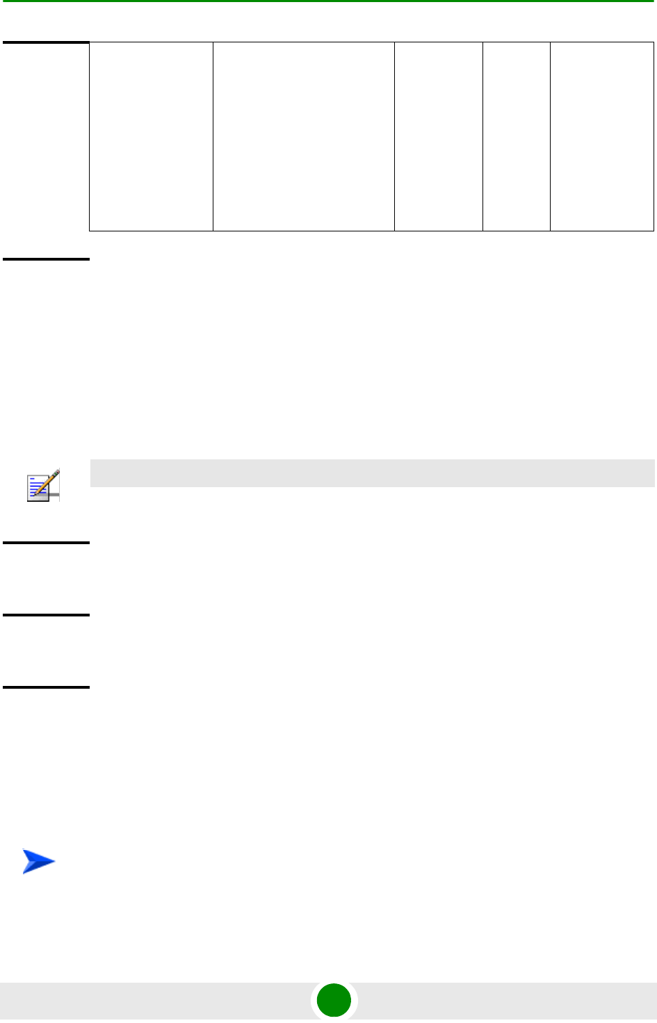
Chapter 4 - Operation and Administration Using the CLI NPU Configuration
4Motion 361 System Manual
4.3.10.15.4.3 Restoring the Default Parameters for the L3 Classification Rule
Run the following command to restore the default configuration for this
classification rule.
npu(config-clsfrule)# no [priority] [iptos-low] [iptos-high]
[iptos-mask] [iptos-enable][phs-rulename]
4.3.10.15.4.4 Managing Protocol Configuration for the L3 Classification Rule
L3 classification rules can classify the packet, based on the value of IP protocol
field. You can configure the value of IP protocol for a given classification rule.
1Enable the IP protocol configuration mode (refer to Section 4.3.10.15.4.4.1)
[iptos-enable] Indicates whether the use of
TOS-based classification is to
be enabled.
Optional By
default,
the use
of
TOS-bas
ed
classifica
tion is
disabled.
The
presence/abse
nce of this flag
indicates that
the use of
TOS-based
classification
should be
enabled/disabl
ed.
Command
Modes
L3 Classification rules configuration mode
NOTE
Refer to Section 4.3.10.15.4.3 for a description and default values of these parameters.
Command
Syntax
npu(config-clsfrule)# no [priority] [iptos-low] [iptos-high]
[iptos-mask] [iptos-enable] [phs-rulename]
Privilege
Level
10
Command
Modes
L3 Classification rules configuration mode
To configure one or more IP protocols:

Chapter 4 - Operation and Administration Using the CLI NPU Configuration
4Motion 362 System Manual
2Enable/disable protocol lists (refer to Section 4.3.10.15.4.4.2 and
Section 4.3.10.15.4.4.3)
3Terminate the protocol configuration mode (refer to Section 4.3.10.15.4.4.4)
In addition, you can, at any time, delete an existing protocol list (refer to
Section 4.3.10.15.4.4.5).
The following example illustrates the (sequence of) commands for enabling the IP
protocol configuration mode, enabling IP protocol 100, and then terminating the
protocol lists configuration mode:
npu(config-clsfrule)# ip-protocol
npu(config-clsfrule-protocol)# protocol-enable 1 100
npu(config-clsfrule-protocol)# exit
4.3.10.15.4.4.1Enabling the IP Protocol Configuration Mode
Run the following command to enable the IP protocol configuration mode.
npu(config-clsfrule)# ip-protocol
You can now enable or disable a protocol list (refer to Section 4.3.10.15.4.4.2 and
Section 4.3.10.15.4.4.3).
4.3.10.15.4.4.2Enabling Protocol Lists
After enabling the protocol configuration mode, run the following command to
enable one or more IP protocol lists:
npu(config-clsfrule-protocol)# protocol-enable <number of
protocols(1-6)> <protocol1> [<protocol2>] [...]
Command
Syntax
npu(config-clsfrule)# ip-protocol
Privilege
Level
10
Command
Modes
L3 Classification rules configuration mode

Chapter 4 - Operation and Administration Using the CLI NPU Configuration
4Motion 363 System Manual
4.3.10.15.4.4.3Disabling Protocol Lists
After enabling the protocol configuration mode, run the following command to
disable one or more IP protocol lists:
npu(config-clsfrule-protocol)# no protocol-enable <number of
protocols(1-6)> <protocol1> [<protocol2>] [...]
Command
Syntax
npu(config-clsfrule-protocol)# protocol-enable <number of protocols(1-6)>
<protocol1> [<protocol2>] [...]
Privilege
Level
10
Syntax
Description Parameter Description Presence Default
Value
Possible
Values
<number of
protocols(1)>
Indicates the number of
protocol lists to be enabled. In
the current release, only one
protocol can be enabled per
classification rule.
Mandatory N/A 1
<protocol1>
[<protocol2>]
[...]
Indicates the IP protocols to
be enabled. In the current
release, only one protocol
can be enabled per
classification rule.
Mandatory N/A 0-255 (Using
standard IANA
protocol
values)
Command
Modes
L3 Classification rules-IP protocol configuration mode
Command
Syntax
npu(config-clsfrule-protocol)# no protocol-enable <number of
protocols(1-6)> <protocol1> [<protocol2>] [...]
Privilege
Level
10

Chapter 4 - Operation and Administration Using the CLI NPU Configuration
4Motion 364 System Manual
4.3.10.15.4.4.4Terminating the Protocol Configuration Mode
Run the following command to terminate the IP protocol configuration mode:
npu(config-clsfrule-protocol)# exit
4.3.10.15.4.4.5Deleting Protocol Lists
You can, at any time, run the following command to delete all protocol lists:
npu(config-clsfrule)# no ip-protocol
Syntax
Description Parameter Description Presence Default
Value
Possible
Values
<number of
protocols(1-6)
>
Indicates the number of
protocol lists to be disabled.
In the current release, only
one protocol can be enabled
per classification rule.
Mandatory N/A 1
<protocol1>
[<protocol2>]
[...]
Indicates the protocols to be
disabled. You are required to
specify at least one protocol
that is to be disabled.
In the current release, the
single previously enabled
protocol should be defined.
Mandatory N/A 0-255
Command
Modes
L3 Classification rules-IP protocol configuration mode
Command
Syntax
npu(config-clsfrule-protocol)# exit
Privilege
Level
10
Command
Modes
L3 Classfication rule-IP protocol configuration mode

Chapter 4 - Operation and Administration Using the CLI NPU Configuration
4Motion 365 System Manual
4.3.10.15.4.5 Managing Source Address Configuration for the L3 Classification Rule
Classification rules can classify the packet, based on the source address of the
packet. You can configure the value of source address for a given classification
rule.
1Enable the source address configuration mode (refer to
Section 4.3.10.15.4.5.1)
2You can now execute any of the following tasks:
»Configure the address mask (refer to Section 4.3.10.15.4.5.2)
»Disable the source address (refer to Section 4.3.10.15.4.5.3)
3Terminate the source address configuration mode (refer to
Section 4.3.10.15.4.5.4)
You can, at any time, delete an existing source address (refer to
Section 4.3.10.15.4.5.5).
The following example illustrates the (sequence of) commands for enabling the
source address configuration mode, configuring the address mask, and then
terminating the source address configuration mode:
npu(config-clsfrule)# srcaddr 10.203.155.20
npu(config-clsfrule-srcaddr)# config addr-enable addr-mask
255.255.0.0
npu(config-clsfrule-srcaddr)# exit
Command
Syntax
npu(config-clsfrule)# no ip-protocol
Privilege
Level
10
Command
Modes
L3 Classfication rule-IP protocol configuration mode
To configure one or more source addresses:

Chapter 4 - Operation and Administration Using the CLI NPU Configuration
4Motion 366 System Manual
4.3.10.15.4.5.1Enabling the Source Address Configuration Mode\ Creating a New
Source Address
To configure the parameters for a source address, first enable the source address
configuration mode. Run the following command to enable the source address
configuration mode. You can also use this command to create a new source
address.
npu(config-clsfrule)# srcaddr <ipv4addr>
If you use this command to specify a new source address, the configuration mode
for the newly created source address is automatically enabled, after which you
can execute any of the following tasks:
Configure the address mask (refer to Section 4.3.10.15.4.5.2)
Disable the source address (refer to Section 4.3.10.15.4.5.3)
After you have executed these tasks, terminate the source address configuration
mode to return to the service classification rule configuration mode (refer to
Section 4.3.10.15.4.5.4).
IMPORTANT
An error may occur if you provide an invalid source IP address. Refer the syntax description for
more information about the appropriate value and format for configuring this parameter.
Command
Syntax
npu(config-clsfrule)# srcaddr <ipv4addr>
Syntax
Description Parameter Description Presence Default
Value
Possible
Values
<ipv4addr> Denotes the IPv4 address of
the source address for which
the configuration mode is to
be enabled. If you want to
create a new source address,
specify the value for the new
source address. The source
address configuration mode
is automatically enabled.
Mandatory N/A Valid IP
Address

Chapter 4 - Operation and Administration Using the CLI NPU Configuration
4Motion 367 System Manual
4.3.10.15.4.5.2Configuring the Address Mask
After enabling the source address configuration mode, run the following command
to configure the address mask for the source address.
npu(config-clsfrule-srcaddr)# config [addr-enable] [addr-mask
<value>]
You can also run this command to enable a source address that is currently
disabled. For details, refer to “Disabling the Source Address” on page 368.
Command
Modes
L3 Classification rules configuration mode
IMPORTANT
An error may occur if you provide an invalid address mask for the source address. Refer the syntax
description for more information about the appropriate value and format for this parameter.
Command
Syntax
npu(config-clsfrule-srcaddr)# config [addr-enable] [addr-mask <value>]
Privilege
Level
10
Syntax
Description Parameter Description Presence Default Value Possible
Values
[addr-enable] Indiactes that the use of
the associated source
address is enabled for
the classification rule
that you are configuring.
If the use of this address
is disabled, the
associated source
address is ignored while
classifying the packet.
Optional By default, the
use of the
associated
source address
is disabled.
The
presence/abse
nce of this flag
indicates that
the use of the
associated
source address
is
enabled/disabl
ed.
[addr-mask
<value>]
Denotes the mask field
that is used to specify a
range of source
addresses.
Optional 255.255.255.25
5
Valid address
mask

Chapter 4 - Operation and Administration Using the CLI NPU Configuration
4Motion 368 System Manual
4.3.10.15.4.5.3Disabling the Source Address
You can run the following command to disable the source address that is
currently enabled:
npu(config-clsfrule-srcaddr)# no addr-enable
4.3.10.15.4.5.4Terminating the Source Address Configuration Mode
Run the following command to terminate the source address configuration mode:
npu(config-clsfrule-srcaddr)# exit
Command
Modes
L3 Classification rules-source address configuration mode
IMPORTANT
To enable this source address, run the following command:
npu(config-clsfrule-srcaddr)# config [addr-enable] [addr-mask <value>]
For details, refer to “Configuring the Address Mask” on page 367.
Command
Syntax
npu(config-clsfrule-srcaddr)# no addr-enable
Privilege
Level
10
Command
Modes
L3 Classification rules-source address configuration mode
Command
Syntax
npu(config-clsfrule-srcaddr)# exit
Privilege
Level
10
Command
Modes
L3 Classfication rule-source address configuration mode

Chapter 4 - Operation and Administration Using the CLI NPU Configuration
4Motion 369 System Manual
4.3.10.15.4.5.5Deleting Source Addresses
You can, at any time, run the following command to delete one or all source
addresses
npu(config-clsfrule)# no srcaddr [<ipv4addr>]
CAUTION
Specify the IP address if you want to delete a specific source address. Otherwise all the configured
source addresses are deleted.
IMPORTANT
An error may occur if you provide an invalid IP address. Refer the syntax description for more
information about the appropriate values and format for configuring this parameter.
Command
Syntax
npu(config-clsfrule)# no srcaddr [<ipv4addr>]
Privilege
Level
10
Syntax
Description Parameter Description Presence Default
Value
Possible
Values
[<ipv4addr>] Denotes the IPv4 address of
the source address that you
want to delete from a
classification rule.
Specify this parameter only if
you want to delete a specific
source address. If you do not
specify a value for this
parameter, all the configured
source addresses of the
classification rule will be
deleted.
Optional N/A Valid IP
Address
Command
Modes
L3 Classification rules configuration mode

Chapter 4 - Operation and Administration Using the CLI NPU Configuration
4Motion 370 System Manual
4.3.10.15.4.6 Managing Destination Address Configuration for the L3 Classification Rule
Classification rules can classify the packet, based on the destination address of
the packet. You can configure the value of destination address for a given
classification rule.
1Enable the destination address configuration mode (refer to
Section 4.3.10.15.4.6.1)
2You can now execute any of the following tasks:
»Configure the address mask (refer to Section 4.3.10.15.4.6.2)
»Disable the destination address (refer to Section 4.3.10.15.4.6.3)
3Terminate the destination address configuration mode (refer to
Section 4.3.10.15.4.6.4)
In addition, you can, at any time, delete an existing destination address (refer to
Section 4.3.10.15.4.6.5).
The following example illustrates the (sequence of) commands for enabling the
source address configuration mode, configuring the address mask, and then
terminating the destination address configuration mode:
npu(config-clsfrule)# dstaddr 10.203.155.22
npu(config-clsfrule-dstaddr)# config addr-enable addr-mask
0.0.255.255
npu(config-clsfrule-srcaddr)# exit
4.3.10.15.4.6.1Enabling the Destination Address Configuration Mode\ Creating a New
Destination Address
To configure the parameters for a destination address, first enable the destination
address configuration mode. Run the following command to enable the
destination address configuration mode. You can also use this command to create
a new destination address.
npu(config-clsfrule)# dstaddr <ipv4addr>
If you use this command to specify a new destination address, the configuration
mode for the newly created destination address is automatically enabled, after
which you can execute any of the following tasks:
To configure one or more destination addresses:

Chapter 4 - Operation and Administration Using the CLI NPU Configuration
4Motion 371 System Manual
Configure the address mask (refer to Section 4.3.10.15.4.6.2)k
Disable the destination address (refer to Section 4.3.10.15.4.6.3)
After you execute these tasks, you can terminate the destination address
configuration mode (refer to Section 4.3.10.15.4.6.4) and return to the
classification rules configuration mode.
4.3.10.15.4.6.2Configuring the Address Mask
Run the following command to configure the address mask for the destination
address.
npu(config-clsfrule-dstaddr)# config [addr-enable] [addr-mask
<value>]
IMPORTANT
An error may occur if you provide an invalid destination IP address. Refer the syntax description for
more information about the appropriate values and format for configuring this parameter.
Command
Syntax
npu(config-clsfrule)# dstaddr <ipv4addr>
Privilege
Level
10
Syntax
Description Parameter Description Presence Default
Value
Possible
Values
<ipv4addr> Denotes the IPv4 address of
the destination address for
which the configuration mode
is to be enabled. If you want
to create a new destination
address, specify the value for
the new destination address.
The destination address
configuration mode is
automatically enabled.
Mandatory N/A Valid IP
Address
Command
Modes
L3 Classification rules configuration mode

Chapter 4 - Operation and Administration Using the CLI NPU Configuration
4Motion 372 System Manual
You can also run this command to enable a destination address that is currently
disabled. For details, refer to “Disabling the Destination Address” on page 372.
4.3.10.15.4.6.3Disabling the Destination Address
Run the following command to disable the destination address that is currently
enabled:
npu(config-clsfrule-dstaddr)# no addr-enable
IMPORTANT
An error may occur if you provide an invalid address mask. Refer the syntax description for more
information about the appropriate values and format for configuring this parameter.
Command
Syntax
npu(config-clsfrule-dstaddr)# config [addr-enable] [addr-mask <value>]
Privilege
Level
10
Syntax
Description Parameter Description Presence Default Value Possible
Values
[addr-enable] Indicates that the use
of the associated
destination address is
enabled for the
classification rule that
you are configuring. If
the use of this address
is disabled, the
associated destination
address is ignored
while classifying the
packet.
Optional By default, the
use of the
associated
destination
address is
disabled.
The
presence/abse
nce of this flag
indicates that
the use of the
associated
destination
address is
enabled/disabl
ed.
[addr-mask
<value>]
Denotes the mask field
that is used to specify a
range of destination
addresses.
Optional 255.255.255.255 Valid address
mask
Command
Modes
L3 Classification rules-destination address configuration mode

Chapter 4 - Operation and Administration Using the CLI NPU Configuration
4Motion 373 System Manual
4.3.10.15.4.6.4Terminating the Destination Address Configuration Mode
Run the following command to terminate the destination address configuration
mode:
npu(config-clsfrule-dstaddr)# exit
4.3.10.15.4.6.5Deleting Destination Addresses
You can, at any time, run the following command to delete one or all destination
addresses
npu(config-clsfrule)# no dstaddr [<ipv4addr>]
Command
Syntax
npu(config-clsfrule-dstaddr)# no addr-enable
Privilege
Level
10
Command
Modes
L3 Classification rules-destination address configuration mode
Command
Syntax
npu(config-clsfrule-dstaddr)# exit
Privilege
Level
10
Command
Modes
L3 Classfication rule-destination address configuration mode
CAUTION
Specify the IP address if you want to delete a specific destination address. Otherwise all the
configured destination addresses are deleted.
IMPORTANT
An error may occur if you provide an invalid IP address. Refer the syntax description for more
information about the appropriate values and format for configuring this parameter.

Chapter 4 - Operation and Administration Using the CLI NPU Configuration
4Motion 374 System Manual
4.3.10.15.4.7 Managing Source Port Configuration for the L3 Classification Rule
Classification can be based on the source port of the packet. You can configure
the value of a source port for a given classification rule.
1Enable the source port configuration mode (refer to Section 4.3.10.15.4.7.1)
2Enable/disable the source port range (refer to
Section 4.3.10.15.4.7.2/Section 4.3.10.15.4.7.3)
3Terminate the source port configuration mode (refer to
Section 4.3.10.15.4.7.4)
In addition, you can, at any time, delete an existing source port configuration
(refer to Section 4.3.10.15.4.7.5).
The following example illustrates the (sequence of) commands for enabling the
source port configuration mode, enabling the source port range, and then
terminating the source port configuration mode:
Command
Syntax
npu(config-clsfrule)# no dstaddr [<ipv4addr>]
Privilege
Level
10
Syntax
Description Parameter Description Presence Default
Value
Possible
Values
[<ipv4addr>] Denotes the IPv4 address of
the destination address that
you want to delete from a
classification rule.
Specify this parameter only if
you want to delete a specific
destination address.
Optional N/A Valid IP
Address
Command
Modes
L3 Classification rules configuration mode
To configure one or more source ports:

Chapter 4 - Operation and Administration Using the CLI NPU Configuration
4Motion 375 System Manual
npu(config-clsfrule)# srcport 20 50
npu(config-clsfrule-srcport)# port-enable
npu(config-clsfrule-srcport)# exit
4.3.10.15.4.7.1Enabling the Source Port Configuration Mode\ Creating a New Source
Port
To configure the parameters for a source port, first enable the source port
configuration mode. Run the following command to enable the source port
configuration mode. You can also use this command to create a new source port.
npu(config-clsfrule)# srcport <start-port> <end-port>
If you use this command to specify a new source port, the configuration mode for
the newly created source port is automatically enabled, after which you can
enable/disable the source port range (refer to
Section 4.3.10.15.4.7.2/Section 4.3.10.15.4.7.3).
You can then terminate the source port configuration mode (refer to
Section 4.3.10.15.4.7.4) and return to the classification rules configuration mode.
IMPORTANT
An error may occur if you provide an invalid value for any of these parameters. Refer the syntax
description for more information about the appropriate values and format for configuring these
parameters.
Command
Syntax
npu(config-clsfrule)# srcport <start-port> <end-port>
Privilege
Level
10
Syntax
Description Parameter Description Presence Default
Value
Possible
Values
<start-port> Denotes the starting value of
port range to be configured.
Mandatory N/A 1-65535
<end-port> Denotes the end value of port
range to be configured.
Mandatory N/A 1-65535

Chapter 4 - Operation and Administration Using the CLI NPU Configuration
4Motion 376 System Manual
4.3.10.15.4.7.2Enabling the Source Port Range
Run the following command to enable the source port range:
npu(config-clsfrule-srcport)# port-enable
You can also run this command to enable a source port range that is currently
disabled. For details, refer to “Disabling the Source Port Range” on page 376.
4.3.10.15.4.7.3Disabling the Source Port Range
Run the following command to disable the source port range that is currently
enabled:
npu(config-clsfrule-srcport)# no port-enable
Command
Modes
L3 Classification rules configuration mode
Command
Syntax
npu(config-clsfrule-srcport)# port-enable
Privilege
Level
10
Command
Modes
L3 Classification rules-source port configuration mode
IMPORTANT
To enable this source port range, run the following command:
npu(config-clsfrule-srcport)# port-enable
For details, refer to “Enabling the Source Port Range” on page 376.
Command
Syntax
npu(config-clsfrule-srcport)# no port-enable
Privilege
Level
10
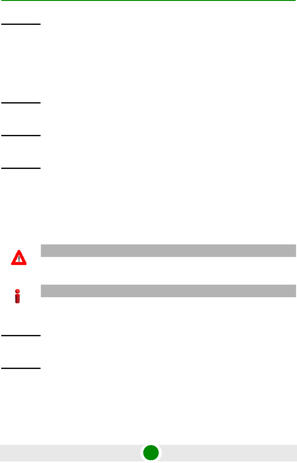
Chapter 4 - Operation and Administration Using the CLI NPU Configuration
4Motion 377 System Manual
4.3.10.15.4.7.4Terminating the Source Port Configuration Mode
Run the following command to terminate the source port configuration mode:
npu(config-clsfrule-srcport)# exit
4.3.10.15.4.7.5Deleting Source Ports
Run the following command to delete one or all source ports
npu(config-clsfrule)# no srcport [<start-port> <end-port>]
Command
Modes
L3 Classification rules-source port configuration mode
Command
Syntax
npu(config-clsfrule-srcport)# exit
Privilege
Level
10
Command
Modes
L3 Classfication rule-source port configuration mode
CAUTION
Specify the start and end port numbers if you want to delete a specific souce port. Otherwise all the
configured source ports are deleted.
IMPORTANT
An error may occur if you provide an invalid value for the start-port and end-port parameters.
Refer the syntax description for more information about the appropriate values and format for
configuring these parameters.
Command
Syntax
npu(config-clsfrule)# no srcport [<start-port> <end-port>]
Privilege
Level
10

Chapter 4 - Operation and Administration Using the CLI NPU Configuration
4Motion 378 System Manual
4.3.10.15.4.8 Managing Destination Port Configuration for the L3 Classification Rule
Classification can be based on the destination port of the packet. You can
configure the value of a destination port for a given classification rule.
1Enable the destination port configuration mode (refer to
Section 4.3.10.15.4.8.1)
2Enable/disable the destination port range (refer to
Section 4.3.10.15.4.8.2/Section 4.3.10.15.4.8.3)
3Terminate the destination port configuration mode (refer to
Section 4.3.10.15.4.8.4)
In addition, you can, at any time, delete an existing destination port configuration
(refer to Section 4.3.10.15.4.8.5).
The following example illustrates the (sequence of) commands for enabling the
destination port configuration mode, enabling the destination port range, and
then terminating the destination port configuration mode:
npu(config-clsfrule)# dstport 50 400
npu(config-clsfrule-dstport)# port-enable
npu(config-clsfrule-dstport)# exit
Syntax
Description Parameter Description Presence Default
Value
Possible
Values
<start-port> Denotes the starting value of
port range to be deleted.
Optional N/A 1-65535
<end-port> Denotes the end value of port
range to be deleted.
Optional N/A 1-65535
Command
Modes
L3 Classification rules configuration mode
To configure one or more destination ports:

Chapter 4 - Operation and Administration Using the CLI NPU Configuration
4Motion 379 System Manual
4.3.10.15.4.8.1Enabling the Destination Port Configuration Mode\ Creating a New
Destination Port
To configure the parameters for a destination port, first enable the destination
port configuration mode. Run the following command to enable the destination
port configuration mode. You can also use this command to create a new
destination port.
npu(config-clsfrule)# dstport <start-port> <end-port>
If you use this command to specify a new destination port, the configuration mode
for the newly created destination port is automatically enabled, after which you
can enable/disable the destination port range (refer to
Section 4.3.10.15.4.8.2/Section 4.3.10.15.4.8.3). After executing these tasks, you
can terminate the destination port configuration mode (refer to
Section 4.3.10.15.4.8.4).
4.3.10.15.4.8.2Enabling the Destination Port Range
You can run the following command to enable the destination port range:
IMPORTANT
An error may occur if you provide an invalid value for the start-port and end-port parameters.
Refer the syntax description for more information about the appropriate values and format for
configuring these parameters.
Command
Syntax
npu(config-clsfrule)# dstport <start-port> <end-port>
Privilege
Level
10
Syntax
Description Parameter Description Presence Default
Value
Possible
Values
<start-port> Denotes the starting value of
port range to be configured.
Mandatory N/A 1-65535
<end-port> Denotes the end value of port
range to be configured.
Mandatory N/A 1-65535
Command
Modes
L3 Classification rules configuration mode

Chapter 4 - Operation and Administration Using the CLI NPU Configuration
4Motion 380 System Manual
npu(config-clsfrule-dstport)# port-enable
You can also run this command to enable a destination port range that is
currently disabled. For details, refer to “Disabling the Destination Port Range” on
page 380.
4.3.10.15.4.8.3Disabling the Destination Port Range
You can run the following command to disable the destination port range that is
currently enabled:
npu(config-clsfrule-dstport)# no port-enable
4.3.10.15.4.8.4Terminating the Destination Port Configuration Mode
Run the following command to terminate the destination port configuration mode:
npu(config-clsfrule-dstport)# exit
Command
Syntax
npu(config-clsfrule-dstport)# port-enable
Privilege
Level
10
Command
Modes
L3 Classification rules-destination port configuration mode
IMPORTANT
To enable this destination port range, run the following command:
npu(config-clsfrule-dstport)# port-enable
For details, refer to “Enabling the Destination Port Range” on page 379.
Command
Syntax
npu(config-clsfrule-srcport)# no port-enable
Privilege
Level
10
Command
Modes
L3 Classification rules-destination port configuration mode
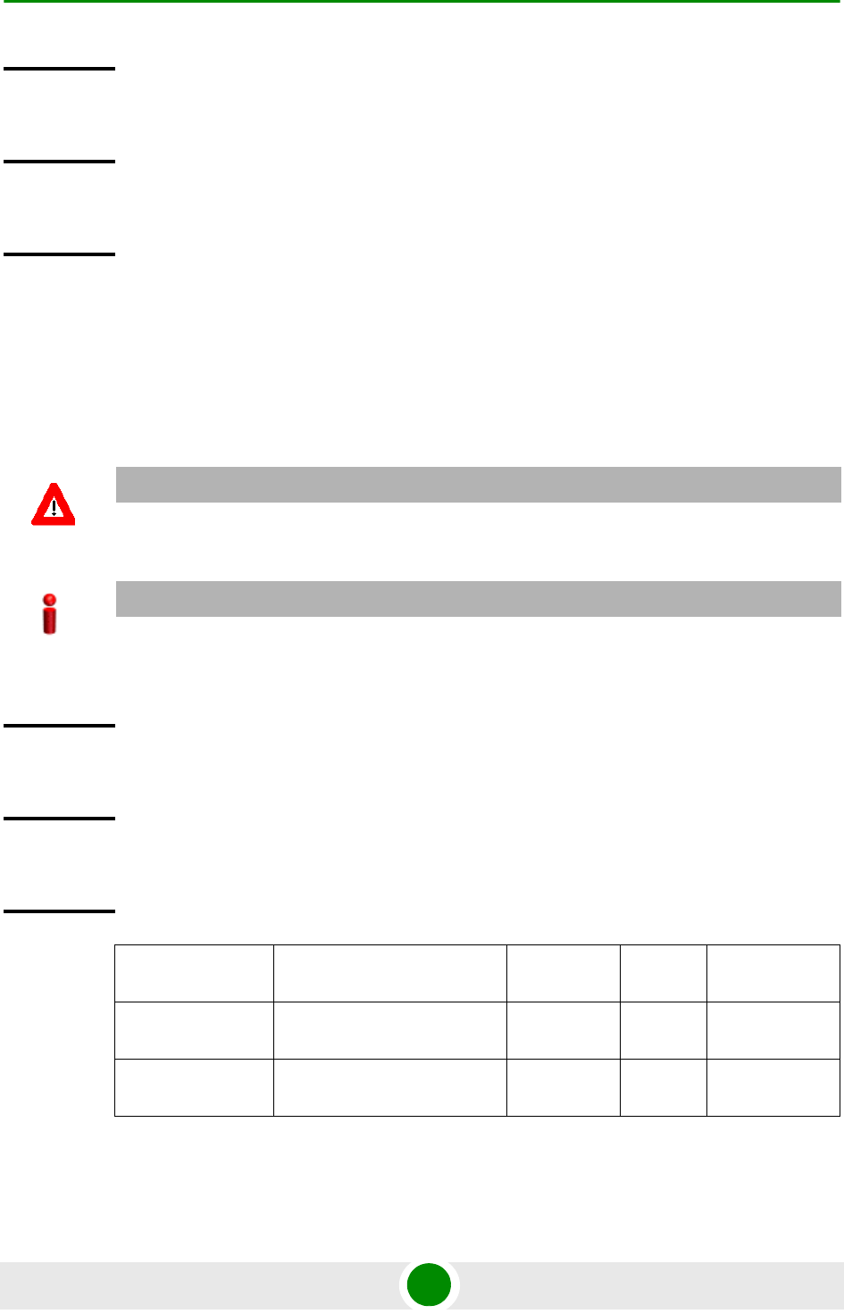
Chapter 4 - Operation and Administration Using the CLI NPU Configuration
4Motion 381 System Manual
4.3.10.15.4.8.5Deleting Destination Ports
Run the following command to delete one or all destination ports
npu(config-clsfrule)# no dstport [<start-port> <end-port>]
Command
Syntax
npu(config-clsfrule-dstport)# exit
Privilege
Level
10
Command
Modes
L3 Classfication rule-destination port configuration mode
CAUTION
Specify the start and end port numbers if you want to delete a specific destination port. Otherwise
all the configured destination ports are deleted.
IMPORTANT
An error may occur if you provide an invalid value for the start-port and end-port parameters.
Refer the syntax description for more information about the appropriate values and format for
configuring these parameters.
Command
Syntax
npu(config-clsfrule)# no dstport [<start-port> <end-port>]
Privilege
Level
10
Syntax
Description Parameter Description Presence Default
Value
Possible
Values
<start-port> Denotes the starting value of
port range to be deleted.
Optional N/A 1-65535
<end-port> Denotes the end value of port
range to be deleted.
Optional N/A 1-65535
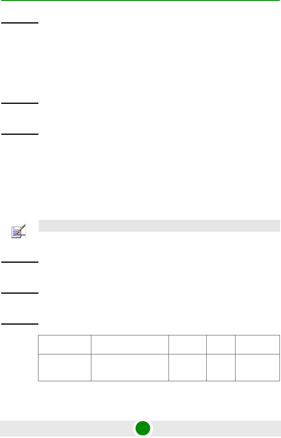
Chapter 4 - Operation and Administration Using the CLI NPU Configuration
4Motion 382 System Manual
4.3.10.15.4.9 Terminating the L3 Classification Rule Configuration Mode
Run the following command to terminate the L3 classification rules configuration
mode:
npu(config-clsfrule)# exit
4.3.10.15.4.10Specifying Configuration Parameters for the L2 Classification Rule
After enabling the classification rules configuration mode for an L2 classification
rule, run the following command to configure the parameters for this
classification rule:
npu(config-clsfrule-L2)# cvid <value(1-4094)>
Command
Modes
L3 Classification rules configuration mode
Command
Syntax
npu(config-clsfrule)# exit
Command
Modes
L3 Classification rules configuration mode
NOTE
You can display configuration information for specific or all classification rules. For details, refer to
Section 4.3.10.15.4.13.
Command
Syntax
npu(config-clsfrule-L2)# cvid <value(1-4094)>
Privilege
Level
10
Syntax
Description Parameter Description Presence Default
Value
Possible
Values
cvid
<value(1-4094)
>
Denotes the Customer VLAN
ID value to be assigned to the
classification rule.
Mandatory N/A 1-4094

Chapter 4 - Operation and Administration Using the CLI NPU Configuration
4Motion 383 System Manual
4.3.10.15.4.11Clearing the configuration of the L3 Classification Rule
Run the following command to clear the configuration of this classification rule
(removing the configured cvid):
npu(config-clsfrule-L2)# no cvid
After clearing the configuration you can define a new cvid for this classification
rule.
4.3.10.15.4.12Terminating the L2 Classification Rule Configuration Mode
Run the following command to terminate the L2 classification rules configuration
mode:
npu(config-clsfrule-L2)# exit
4.3.10.15.4.13Displaying Configuration Information for Classification Rules
To display all or specific classification rules, run the following command:
npu# show clsf-rule [<rulename>]
Specify the classification rule name if you want to display configuration
information for a particular rule. Do not specify a value for this parameter if you
want to view configuration information for all classification rules.
Command
Modes
L2 Classification rules configuration mode
Command
Syntax
npu(config-clsfrule-L2)# no cvid
Privilege
Level
10
Command
Modes
L2 Classification rules configuration mode
Command
Syntax
npu(config-clsfrule-L2)# exit
Command
Modes
L2 Classification rules configuration mode

Chapter 4 - Operation and Administration Using the CLI NPU Configuration
4Motion 384 System Manual
IMPORTANT
An error may occur if you provide an invalid value for the rulename parameter. Refer the syntax
description for more information about the appropriate values and format for configuring this
parameters.
Command
Syntax
npu# show clsf-rule [<rulename>]
Privilege
Level
1
Syntax
Description Parameter Description Presence Default
Value
Possible
Values
[<rulename>] Denotes the name of the
classification rule that you
want to display.
Specify this parameter only if
you want to display a specific
classification rule. If you do
not specify a rule name, it
displays all configured
classification rules.
Optional N/A String
Display
Format for
each L3
rule
Classification Rule Configuration :
ClsfRulename <value>
clsfRuleType: L3
Priority <value>
Phs rulename <value>
IpTosLow <value> IpTosHigh <value> IpTosMask <value> IpTosEnable <0/1>
clsfRuleSrcAddr <value> clsfRuleMask <value> SrcAddrEnable <0/1>
clsfRuleDstAddr <value> clsfRuleAddrMask <value> DstAddrenable <0/1>
clsfRuleSrcPort Start <value> clsfRuleSrcPort End <value>
clsfRulePortEnable <0/1>
clsfRuleDstPort Start <value> clsfRuleDstPort End <value>
clsfRulePortEnable <0/1>

Chapter 4 - Operation and Administration Using the CLI NPU Configuration
4Motion 385 System Manual
4.3.10.15.4.14Deleting Classification Rules
Run the following command to delete one or all classification rules:
npu(config)# no clsf-rule [<rulename>]
Display
Format for
each L2
rule
ClsfRulename <value>
clsfRuleType: L2
Cvid <value>
Command
Modes
Global command mode
CAUTION
Specify the rule name if you want to delete a specific classification. Otherwise all the configured
classification rules are deleted.
Command
Syntax
npu(config)# no clsf-rule [<rulename>]
Privilege
Level
10
Syntax
Description Parameter Description Presence Default
Value
Possible
Values
[<rulename>] Denotes the name of the
classification rule that you
want to delete. Specify this
parameter only if you want to
delete a specific classification
rule, otherwise all configured
classification rules are
deleted.
Optional N/A String
Command
Modes
Global configuration mode

Chapter 4 - Operation and Administration Using the CLI NPU Configuration
4Motion 386 System Manual
4.3.10.16 Configuring PHS Rules
Packet Header Suppression (PHS) is a mechanism that conserves air-interface
bandwidth by removing parts of the packet header that remain constant along the
traffic session. PHS operates by allowing the MS and ASN-GW to associate PHS
rules to each service flow.
When PHS is enabled, a repetitive portion of the payload headers of higher layers
is suppressed in the MAC SDU by the sending entity and restored by the receiving
entity. At the uplink, the sending entity is the MS and the receiving entity is the
NPU. At the downlink, the sending entity is the NPU, and the receiving entity is
the MS. If PHS is enabled at the MAC connection, each MAC SDU is prefixed with
a PHSI, which references the Payload Header Suppression Field (PHSF).
For instance, the ASN-GW will associate a PHS rule to each provisioned service
flow intended for VoIP traffic that will suppress the IP address field from the IP
header and other unvarying fields (e.g. protocol version) from the IP and RTP
headers. The PHS rules are provisioned on a per-service profile name basis. (For
details, refer Section 4.3.10.15.4.)
PHS rules define:
Header fields that need to be suppressed
Static values that can be configured for the suppressed header fields
1Enable the PHS rules configuration mode (refer to Section 4.3.10.16.1)
2Configure the parameters for the PHS rule (refer to Section 4.3.10.16.2)
3Terminate the PHS rules configuration mode (refer to Section 4.3.10.16.3)
You can, at any time, display configuration information (refer to
Section 4.3.10.16.5) or delete an existing PHS rules (refer to Section 4.3.10.16.4).
The following example illustrates the (sequence of) commands for enabling the
PHS rules configuration mode, configuring the parameters of a PHS rule, and then
terminating the PHS configuration mode, should be executed as shown in the
example below:
npu(config)# phs-rule phs-rule1
To configure one or more PHS rules:

Chapter 4 - Operation and Administration Using the CLI NPU Configuration
4Motion 387 System Manual
npu(config-phsrule)# config field
000000000000000000000000FFFFFFFF00000000 mask 000F00 verify 0 size
20
npu(config-phsrule)# exit
4.3.10.16.1 Enabling the PHS Rules Configuration Mode /Creating a New PHS Rule
To configure the parameters for a PHS rule, first enable the PHS rules
configuration mode. Run the following command to enable the PHS rules
configuration mode. You can also use this command to create a new PHS rule.
npu(config)# phs-rule <rulename>
If you use this command to create a new PHS rule, the configuration mode for this
PHS rule is automatically enabled, after which you can configure the parameters
for the PHS rule (refer to Section 4.3.10.16.2). You can then terminate the PHS
rules configuration mode (refer to Section 4.3.10.16.3) and return to the global
configuration mode.
4.3.10.16.2 Configuring Parameters for the PHS Rule
Run the following command to configure the parameters of the PHS rule:
npu(config-phsrule)# config <[field <value>] [mask <value>] [verify
<value>] [size <value>]>
Command
Syntax
npu(config)# phs-rule <rulename>
Privilege
Level
10
Syntax
Description Parameter Description Presence Default
Value
Possible
Values
<rulename> Denotes the PHS rule for
which the PHS configuration
mode is to be enabled.
Mandatory N/A String (1 to 11
characters)
Command
Modes
Global configuration mode

Chapter 4 - Operation and Administration Using the CLI NPU Configuration
4Motion 388 System Manual
NOTE
You can display configuration information for specific or all PHS rules. For details, refer
Section 4.3.10.16.5.
IMPORTANT
An error may occur if you provide an invalid value for any of these parameters. Refer the syntax
description for more information about the appropriate values and format for configuring these
parameters.
Command
Syntax
npu(config-phsrule)# config <[field <value>] [mask <value>] [verify
<value>] [size <value>]>
Privilege
Level
10
Syntax
Description Parameter Description Presence Default
Value
Possible
Values
[field
<value>]
Denotes the PHSF value, that
is, the header string to be
suppressed.
Mandatory N/A String. This
parameter is of
format
"0x000000000
000000000000
000000000000
0000000".
Here Octet(x),
x=20 bytes,
each Byte will
represent two
characters
when used as
string like in
xml file.

Chapter 4 - Operation and Administration Using the CLI NPU Configuration
4Motion 389 System Manual
4.3.10.16.3 Terminating the PHS Rules Configuration Mode
Run the following command to terminate the PHS rules configuration mode:
npu(config-phsrule)# exit
[mask <value>] Indicates the PHSM, which
contains the bit-mask of the
PHSF with the bits set that is
to be suppressed.
Mandatory N/A String This
parameter is of
format
"0x000000".
Here Octet(x),
x=3 bytes,
each Byte will
represent two
characters
when used as
string like in
xml file.
[verify
<value>]
Indicates whether the PHS
header is to be verified.
Optional 0 (No) 0: Indicates
that the
PHS
header
should be
verified.
1: Indicates
that the
PHS
header
should not
be verified.
[size <value>]Indicates the size in bytes of
the header to be suppressed.
Mandatory N/A 0-20
Command
Modes
PHS rules configuration mode
Command
Syntax
npu(config-phsrule)# exit
Privilege
Level
10
Command
Modes
PHS rulesconfiguration mode
Chapter 4 - Operation and Administration Using the CLI NPU Configuration
4Motion 390 System Manual
4.3.10.16.4 Deleting PHS Rules
Run the following command to delete one or all PHS rules:
npu(config)# no phs-rule [<rulename>]
4.3.10.16.5 Displaying Configuration Information for PHS Rules
To display all or specific PHS rules, run the following command:
npu# show phs-rule [<rulename>]
Specify the rule name if you want to display configuration information for a
particular PHS rule. Do not specify a value for this parameter if you want to view
configuration information for all PHS rule.
CAUTION
Specify the rule name if you want to delete a specific PHS rule. Otherwise all the configured PHS
rules are deleted.
Command
Syntax
npu(config)# no phs-rule [<rulename>]
Privilege
Level
10
Syntax
Description Parameter Description Presence Default
Value
Possible
Values
[<rulename>] Denotes the rule name of the
PHS rule that you want to
delete.
Specify a value for this
parameter if you want to
delete a specific PHS rule. Do
not specify a value for this
parameter, if you want to
delete all PHS rules.
Optional N/A String
Command
Modes
Classfication rule-IP protocol configuration mode

Chapter 4 - Operation and Administration Using the CLI NPU Configuration
4Motion 391 System Manual
4.3.10.17 Managing the ASN-GW Keep-Alive Functionality
Once an MS enters the network, its context is stored in ASN entities (BS,
ASN-GW). Dynamically, MS context could be transferred/updated (during HO and
re-authentication) to other entities or duplicated to other entities (separation
between anchor functions such as Authenticator, Data Path and Relay Data
Path).
IMPORTANT
An error may occur if you provide an invalid value for the rulename parameter. Refer the syntax
description for more information about the appropriate values and format for configuring this
parameter.
Command
Syntax
npu# show phs-rule [<rulename>]]
Privilege
Level
1
Syntax
Description Parameter Description Presence Default
Value
Possible
Values
[<rulename>] Denotes the rule name of the
PHS rule that you want to
delete.
Specify a value for this
parameter if you want to
delete a specific PHS rule. Do
not specify a value for this
parameter, if you want to
delete all PHS rules.
Optional N/A String
Display
Format
PHS Configuration :
rulename field mask verify size
<value> <value> <value> <value> <value>
…….
Command
Modes
Global command mode

Chapter 4 - Operation and Administration Using the CLI NPU Configuration
4Motion 392 System Manual
In certain cases, such as entity reset, other entities are not aware of service
termination of an MS in that entity, and keep maintaining the MS context. This
may result in service failure, excessive consumption of memory resources and
accounting mistakes.
The keep-alive mechanism should be used to clear MS context from all network
entities when it is de-attached from the BS, and de-register MS from the network
when its context becomes unavailable in one of its serving function locations.
When the keep-alive mechanism is enabled the ASN-GW periodically polls other
ASN entities-of-interest (BSs and other ASN-GW) and waits for their responses. In
case of no keep-alive response, the ASN-GW shall make further actions, such as
clearing the applicable MS(s) context.
The ASN-GW builds a list of BS-of-interest and ASN-GW-of-interest which it must
poll. ASN-GW shall poll other ASN-GW in case data-path was established over R4
during inter-ASN HO (hierarchical data-path establishment).
The list shall be dynamically updated; the ASN-GW tracks all BSID(s) in all MS(s)
contexts it holds, and dynamically updates the list of BSs-of-interest. When a new
MS is attached to a BS that does not exist in the list, it will be added it to the list.
When the last MS(s) with specific BSID makes network exit, the ASN-GW shall
remove the BS from the list.
The same dynamic behavior applies also to ASN-GW-of-interest list. When
hierarchical data-path is established, the Data Path Function ASN-GW updates
its ASN-GW-of-Interest list with Relay Data Path ASN-GW and vice-versa. The
trigger is R4 data-path creation.
The ASN-GW periodically polls the BS(s) and ASN-GW(s) for keep-alive. The
polling mechanism is independent and unrelated for every BS-of-interest or
ASN-GW-of-interest the ASN-GW polls.
The keep-alive mechanism uses configurable retry timer and retries counter.
Upon expiration of the retry timer, the ASN-GW resends the ASN Keep-Alive
request message. Upon expiration of the retries counter, the ASN-GW assumes
failure of the polled BS/ASN-GW and clears the contexts of all MS(s) served by
that BS/ASN-GW.
In addition, the ASN-GW verifies that for each polled entity that the
"Last-Reset-Time" UTC value of poll N+1 is equal to the value of poll N. If the
"Last-Reset-Time" UTC value of poll N+1 is higher than the value of poll N, this
mean that the BS/ASN-GW went through reset state during the interval between
two consecutive polls. In this case, the ASN-GW shall clear all MS(s) contexts,
served by that specific BS/ASN-GW that are "older" than BS/ASN-GW life after

Chapter 4 - Operation and Administration Using the CLI NPU Configuration
4Motion 393 System Manual
reset (through calculation of difference between polled entity "Last-Reset-Time"
received on poll N+1 and self UTC).
If the ASN-GW is the authenticator for the MS(s) the failing BS served, then in
addition to context clearance it also sends R3 Accounting-Request (Stop) message
including a release indication to AAA.
If ASN-GW is the Data Path Function for the MS(s) that the failing BS/Relay Data
Path ASN-GW served, then in addition to context clearance it also sends R4
NetExit_MS_State_Change_Req (or equivalent - according to R6 IOT spec
procedure) message to the Authenticator which in turn sends R3
Accounting-Request (Stop) message including a release indication to AAA
When keep-alive fails, ASN-GW generates an alarm and log the event.
Regardless of the enable/disable status of the keep-alive mechanism in the
ASN-GW, it replies to ASN_Keep_Alive_Req received from other ASN-GWs/BSs
with ASN_Keep_Alive_Rsp. that includes also its "Last-Reset-Time". It responds
only if all its functions operate properly. In case one of the functions fails, the
ASN-GW shall not respond to the keep-alive poll.
4.3.10.17.1 Configuring ASN-GW Keep-Alive Parameters
To configure one or several keep-alive parameters, run the following command:
npu(config)# set keep-alive ([asnGwKeepAliveTmr <integer (10-1000)>]
[asnGwKeepAliveRtxLmt <integer (1-10)>] [asnGwKeepAliveRespTmr <integer
(100-10000)>] [asnKeepAliveEnable <enable|disable>])
Command
Syntax
npu(config)# set keep-alive ([asnGwKeepAliveTmr <integer (10-1000)>]
[asnGwKeepAliveRtxLmt <integer (1-10)>] [asnGwKeepAliveRespTmr <integer
(100-10000)>] [asnKeepAliveEnable <enable|disable>])
Privilege
Level
10

Chapter 4 - Operation and Administration Using the CLI NPU Configuration
4Motion 394 System Manual
4.3.10.17.2 Displaying Configuration Information for ASN-GW Keep-Alive
Parameters
To display the ASN-GW keep-alive parameters, run the following command:
npu# show keep-alive
Syntax
Description Parameter Description Presence Default
Value
Possible
Values
[asnGwKeepAliv
eTmr <integer
(10-1000)>]
The period ln seconds
between polling sessions.
asnGwKeepAliveTmr x 1000
(value in milliseconds) cannot
be lower than
asnGwKeepAliveRespTmr x
(asnGwKeepAliveRtxLmt +1).
Optional 60 10-1000
[asnGwKeepAl
iveRtxLmt
<integer
(1-10)>]
Maximum number of retries if
asnGwKeepAliveRespTmr
has expired without getting a
response.
Optional 3 1-10
[asnGwKeepAliv
eRespTmr
<integer
(100-10000)>]
Time in milliseconds to wait
for a response before
initiating another polling
attempt or reaching a
decision that the polled entity
has failed (if the maximum
number of retries set by
asnGwKeepAliveRtxLmt has
been reached).
Optional 500 100-10000
[asnKeepAliv
eEnable
<enable|disa
ble>]
Enable/Disable the ASN-GW
keep-alive mechanism.
Optional disable enable
disable
Command
Modes
Global configuration mode
Command
Syntax
npu# show keep-alive

Chapter 4 - Operation and Administration Using the CLI NPU Configuration
4Motion 395 System Manual
4.3.11 Configuring Logging
Logs can be generated to record events that occur with respect to the following
system modules:
System startup procedures: Refers to all procedures/events that occur during
system startup.
NPU/AU upgrade procedures: Refers to all the procedures executed while
upgrading the NPU/AU.
Fault management procedures: Refers to internal processes that are executed
for monitoring erroneous conditions or fault conditions.
System performance procedures: Refers to internal processes that are
executed for monitoring system performance.
Shelf management procedures: Refers to internal processes that are executed
for monitoring the health and temperature of all hardware components (other
than the NPU) such as the AU, PIU and PSU.
WiMAX signaling protocols: Refers to all the protocols that implement the
ASN-GW functionality.
User interface: Refers to the command line or remote management interface
used for executing all user-initiated events such as system shut down or reset.
Privilege
Level
1
Display
Format
% Asn-gateway Keep Alive Configuration
asnGwKeepAliveEnable : <enable/disable>
asnGwKeepAliveTmr : <value>
asnGwKeepAliveRtxLmt : <value>
asnGwKeepAliveRespTmr : <value>
Command
Modes
Global cpmmand mode

Chapter 4 - Operation and Administration Using the CLI NPU Configuration
4Motion 396 System Manual
AU Manager: Refers to all internal processes used for fault, configuration, and
performance management for AU.
You can specify the severity level for which log messages are to be generated for
each module. Logs are generated for events for which the severity level is equal to
or higher than the configured level. The following are the severity levels that you
can configure for each module:
Emergency
Alert
Critical
Error
Warning
Notice
Information
By default, system-level logging is enabled. The system stores a maximum of 1000
log and trace messages. The system stores log and trace messages using the cyclic
buffer method. That is, when there are more than 1000 messages, the system
overwrites the oldest log and trace messages.
To configure logging, first specify system-level logging that is applicable across the
entire system. You can then configure logging, individually for each system
module. This section describes the commands to be used for:
“Managing System-level Logging” on page 397
“Configuring Module-level Logging” on page 406
IMPORTANT
The Syslog utility is used to implement the logging feature for 4Motion.
IMPORTANT
It is recommended that you periodically make backups of log messages before these are
overwritten. For details, refer to “Making a Backup of Log Files on the NPU Flash” on
page 403.

Chapter 4 - Operation and Administration Using the CLI NPU Configuration
4Motion 397 System Manual
4.3.11.1 Managing System-level Logging
System-level logging refers to all the procedures to be executed for managing
logging for the entire system. To manage system-level logging:
Enable/disable logging across the entire system, and specify the destination (a
file on the local system or on an external server) where logs are to be
maintained.
Make periodic backups of log files.
You can, at any time, view the current log destination or delete log files from the
NPU flash. After you have enabled/disabled system-level logging and specified the
destination for storing log messages, you can configure logging separately for each
module. This section describes the commands to be used for:
“Enabling System-level Logging” on page 397
“Disabling Logging to File or Server” on page 399
“Displaying System-level Logs” on page 401
“Displaying the Current Log Destination” on page 402
“Making a Backup of Log Files on the NPU Flash” on page 403
“Deleting Backup Log Files from the NPU Flash” on page 405
4.3.11.1.1 Enabling System-level Logging
You can enable logging for the entire system and specify the destination where
logs should be written. The destination can be either written to:
File
External server (Log files are sent to the external server in the Syslog log
format. The Syslog daemon on the external server can save these log messages
in the appropriate format depending upon the server configuration.)
By default, system-level logging is enabled. To view whether the system-level
logging is enabled/disabled for logging to file or server. For details, refer
Section 4.3.11.1.4.

Chapter 4 - Operation and Administration Using the CLI NPU Configuration
4Motion 398 System Manual
The system maintains a maximum of 1000 log and trace messages. The system
stores log and trace messages using the cyclic buffer method. That is, when there
are more than 1000 messages, the system overwrites the oldest log and trace
messages.
To enable system-level logging, run the following command:
npu(config)# log destination {file | server <IP address>}
IMPORTANT
If you have enabled writing of log messages to file, it is recommended that you periodically make a
backup of this log file. This is because log messages that are written to file are deleted after system
reset. For more information about making backups of log files on the NPU flash, refer to
Section 4.3.11.1.5.
NOTE
After you execute this command, logging is enabled for the entire system. You may also configure
logging separately for each system module. For details, refer to Section 4.3.11.2.
IMPORTANT
An error may occur if:
Logging is already enabled for the requested destination (file or server).
Logging is enabled to a server with a different IP address. Because logging can be enabled to
only one external server, you can specify another server IP address after you disable logging to
the existing server IP address. For more information about disabling logging to server, refer
“Disabling Logging to File or Server” on page 399.
An internal error has occurred.
You have specified the IP address in an invalid format. Specify the IP address in the format,
XXX.XXX.XXX.XXX.
Command
Syntax
npu(config)# log destination {file | server <IP address>}
Privilege
Level
10

Chapter 4 - Operation and Administration Using the CLI NPU Configuration
4Motion 399 System Manual
4.3.11.1.2 Disabling Logging to File or Server
To disable logging to file or server, run the following command:
npu(config)# no log destination {file | server <IP address>}
Syntax
Description Parameter Description Presence Default
Value
Possible
Values
{file|server
<IP address>}
Indicates whether logs are to
be written to a file or server.
Mandatory N/A file:
Indicates
that logs
are to be
written to a
file. (Logs
written to
file are not
maintained
after
system
reset;
periodically
save the log
file to flash.)
For details,
refer to
Section 4
.3.11.1.5.
server:
Indicates
that logs
are to be
written to
an external
server.
Specify the
server IP
address of
the server
in the
format,
XXX.XXX.X
XX.XXX.
Command
Modes
Global configuration mode

Chapter 4 - Operation and Administration Using the CLI NPU Configuration
4Motion 400 System Manual
IMPORTANT
An error may occur if:
Logging is already disabled for the requested destination (file or server).
An internal error has occurred.
The server IP address that you have specified does not exist.
Command
Syntax
npu(config)# no log destination {file | server <IP address>}
Privilege
Level
10

Chapter 4 - Operation and Administration Using the CLI NPU Configuration
4Motion 401 System Manual
4.3.11.1.3 Displaying System-level Logs
To display system-level logs, run the following command:
npu# show logs
Syntax
Description Parameter Description Presence Default
Value
Possible
Values
{file|server
<IP address>}
Indicates whether the
system-level logs are to be
disabled for a file or server.
Mandatory N/A file:
Indicates
that
system-leve
l logging to
a file is to
be
disabled.
server<ip
address>:
Indicates
that
system-leve
l logging to
a server is
to be
disabled.
Specify the
IP address
if you want
to disable
logging to a
specific
server.
Otherwise
logging is
disabled for
the server
that was
last
enabled for
logging.
Provide the
IP address
in the
format,
XXX.XXX.X
XX.XXX.
Command
Modes
Global configuration mode

Chapter 4 - Operation and Administration Using the CLI NPU Configuration
4Motion 402 System Manual
When you run this command, all the log messages are displayed. (4Motion
maintains a maximum of 1000 log and trace messages.) If you want to filter log
messages to be displayed, run the following command to specify the filter criteria:
npu# show logs [filter | grep <string>]
For example, if you want to view log messages pertaining to only Error logs, run
the following command:
npu# show logs filter|grep ERROR
4.3.11.1.4 Displaying the Current Log Destination
To view the current log destination, that is, whether logs are written to file or an
external server, run the following command:
npu# show log destination
IMPORTANT
An error may occur if:
There are no logs to be displayed.
The log files are inaccessible or an internal error occurred while processing the result.
Command
Syntax
npu# show logs [filter | grep <string>]
Privilege
Level
1
Syntax
Description Parameter Description Presence Default
Value
Possible
Values
[filter | grep
<string>]
Indicates the criteria for
filtering the log messages to
be displayed.
Optional N/A String
Command
Modes
Global command mode

Chapter 4 - Operation and Administration Using the CLI NPU Configuration
4Motion 403 System Manual
4.3.11.1.5 Making a Backup of Log Files on the NPU Flash
The system stores a maximum of 1000 log and trace messages in the log file, after
which the oldest messages are overwritten. This log file resides in the TFTP boot
directory (/tftpboot/management/system_log/) of the NPU. You can TFTP this file
from the NPU flash. You can display the list of log files residing on the NPU flash.
For details, refer Section 4.3.11.1.7.
In addition, logs written to file are not maintained after system reset. If you have
enabled writing of logs to file, it is recommended that you periodically make a
backup of log messages on the NPU flash.
When you make a backup of log files on the NPU flash, the last 1000 log and trace
messages are stored in a compressed file, which is saved on the NPU flash. There
is no limit on the number of log files that can be saved unless there is inadequate
space on the NPU flash.
IMPORTANT
An error may occur if an internal error occurs when you execute this command.
Command
Syntax
npu# show log destination
Privilege
Level
1
Display
Format
Logfile(<file name>) : Enabled/Disabled
Log Server(<IP address>) : Enabled/Disabled
Command
Modes
Global command mode
IMPORTANT
You can display a list of log files that are currently residing on the NPU flash. For details, refer
Section 4.3.11.1.7.

Chapter 4 - Operation and Administration Using the CLI NPU Configuration
4Motion 404 System Manual
Run the following command to make a backup of the log and trace messages
(written to file), on the NPU flash:
npu(config)# save log file <file name.gz>
When you run this command, the last 1000 log and trace messages are stored in
the compressed file, which is saved on the NPU flash.
IMPORTANT
Trace messages are also written to the same file as log messages (provided you have enabled
writing of trace messages to file.) When you make a backup of log files written to file, the backup file
also contains trace messages (provided you have enabled writing of trace messages to file). For
more information about configuring traces, refer Section 4.11.1.1.
IMPORTANT
An error may occur if:
You have specified the file name in an invalid format. Because the backup log file is a
compressed file, always suffix the file name with .gz.
The length of the file name has exceeded 255 characters.
The system was unable to compress the file or save the compressed file to flash.
A processing error has occurred.
Command
Syntax
npu(config)# save log file <file name>
Privilege
Level
10
Syntax
Description Parameter Description Presence Default
Value
Possible
Values
<file name> Indicates the name of the
compressed file that contains
the last 1000 log and trace
messages. Always suffix the
file name with .gz.
Mandatory N/A <file name>.gz

Chapter 4 - Operation and Administration Using the CLI NPU Configuration
4Motion 405 System Manual
4.3.11.1.6 Deleting Backup Log Files from the NPU Flash
You can delete the backup log files from the NPU flash. It is recommended that
you periodically make a backup of these log files, and delete these from the NPU
flash.
To delete log and trace backup files from the NPU flash, run the following
command:
npu(config)# erase log file [<file name>]
Command
Modes
Global configuration mode
IMPORTANT
Trace and log messages are stored in the same backup file on the NPU flash. When you execute
this procedure, trace messages are also deleted from the NPU flash. For details, refer to
“Managing System-level Tracing” on page 822.
CAUTION
Specify the file name if you want to delete a specific backup file. Otherwise all the backup files
residing in the NPU flash are deleted.
IMPORTANT
An error may occur if:
The file name that you have specified does not exist.
A processing error has occurred.
Command
Syntax
npu(config)# erase log file [<file name>]
Privilege
Level
10

Chapter 4 - Operation and Administration Using the CLI NPU Configuration
4Motion 406 System Manual
4.3.11.1.7 Displaying Log Files Residing on the NPU Flash
You can display a list of log files that are residing on the NPU flash. For details,
refer Section 4.10.4.
4.3.11.2 Configuring Module-level Logging
You can configure logging (enable/disable) separately for the following modules,
and define the severity level for which logging is required:
System startup procedures
NPU/AU upgrade procedures
Fault management procedures
System performance procedures
Shelf management procedures
WiMAX signaling protocols
User interface
AU management procedures
This section describes the commands to be used for:
Syntax
Description Parameter Description Presence Default
Value
Possible
Values
[<file name>] Indicates the name of the
compressed log file to be
deleted. If you do not specify
the file name, all the log files
residing in the NPU flash are
deleted.
Always suffix the file name
with .gz.
Optional N/A <file name>.gz
Command
Modes
Global configuration mode

Chapter 4 - Operation and Administration Using the CLI NPU Configuration
4Motion 407 System Manual
“Configuring the Log Severity Level” on page 407
“Displaying Configuration Information for Module-level Logging” on page 409
“Disabling Module-level Logging” on page 410
4.3.11.2.1 Configuring the Log Severity Level
You can configure the severity level for logs to be generated for each module. This
means that if an event occurs for a module for which the severity level is equal to
or higher than the configured level, a log is generated. The following are the
severity levels (highest to lowest) that can be configured for each module:
Emergency
Alert
Critical
Error
Warning
Notice
Information
To specify the severity level for each module for which logs are to be created, run
the following command:
npu(config)# log level
[{StartupMgr|SWDownload|FaultMgr|PerfMgr|ShelfMgr|SIGASN|UserIF|AU
Mgr}] {EMERG|ALERT|CRIT|ERROR|WARN|NOTICE|INFO}
The parameters in this command correspond to the system modules/procedures
listed in the following table:
IMPORTANT
By default, logging is enabled for all modules, and the severity level is Error. The severity levels
recorded in 4Motion log messages are defined in RFC 3164.

Chapter 4 - Operation and Administration Using the CLI NPU Configuration
4Motion 408 System Manual
Specify the module name if you want to configure the severity level separately for
this module. If you do not specify the name of the module, the severity level that
you configure in this command is applied to all modules.
For example, run the following command if you want logs to be created for WiMAX
signaling protocols when the severity level is Warning or higher:
npu(config)# log level SIGASN WARN
Or run the following command to set the severity level to Error for all modules:
npu(config)# log level ERROR
Table 4-21: Modules for which Logging can be Enabled
Parameter Refers to...
StartupMgr System startup procedures
SWDownload Software upgrade procedures
FaultMgr Fault management procedures
ShelfMgr Shelf management procedures
SIGASN WiMAX signaling protocols
UserIF User-initiated procedures
AUMgr Internal processes used for managing AU
PerfMgr Performance management procedures
NOTE
You can display the currently configured severity levels for each module. For details, refer
Section 4.3.11.2.2.
Command
Syntax
npu(config)# log level
[{StartupMgr|SWDownload|FaultMgr|PerfMgr|ShelfMgr|SIGASN|UserIF|AUMgr}]
{EMERG|ALERT|CRIT|ERROR|WARN|NOTICE|INFO}
Privilege
Level
10

Chapter 4 - Operation and Administration Using the CLI NPU Configuration
4Motion 409 System Manual
4.3.11.2.2 Displaying Configuration Information for Module-level Logging
To display the log level configured for one or all modules, run the following
command.
npu(config)# show log level
[{StartupMgr|SWDownload|FaultMgr|PerfMgr|ShelfMgr|SIGASN|UserIF|AU
Mgr}]
Specify the module for which you want to view the configured severity level. If you
do not specify the name of the module, the log level configured for all modules is
displayed.
Syntax
Description Parameter Description Presence Default
Value
Possible
Values
[{StartupMgr|S
WDownload|Faul
tMgr|PerfMgr|
ShelfMgr|SIGAS
N|UserIF|AUMg
r}]
Indicates the name of the
module for which the severity
level is to be specified.
If you do not specify any
value for this parameter, the
severity level that you specify
is applied for all modules. For
more information about these
parameters, refer
Table 4-21.
Optional N/A StartupMgr
SWDownloa
d
FaultMgr
PerfMgr
ShelfMgr
SIGASN
UserIF
AUMgr
{EMERG|ALERT|
CRIT|ERROR|WA
RN|NOTICE|INF
O}
Indicates the severity level to
be applied to a particular or
all modules.
Mandatory Error EMERG
ALERT
CRIT
ERROR
WARN
NOTICE
INFO
Command
Modes
Global configuration mode

Chapter 4 - Operation and Administration Using the CLI NPU Configuration
4Motion 410 System Manual
4.3.11.2.3 Disabling Module-level Logging
To disable logging for one or all system modules, run the following command:
npu(config)# no log level
[{StartupMgr|SWDownload|FaultMgr|PerfMgr|ShelfMgr|SIGASN|UserIF|AU
Mgr}]
Specify the name of the module if you want to disable logging for a specific
module. If you do not specify the module name, logging is disabled for all
modules.
Command
Syntax
npu(config)# show log level
[{StartupMgr|SWDownload|FaultMgr|PerfMgr|ShelfMgr|SIGASN|UserIF|AUMgr}]
Privilege
Level
1
Syntax
Description Parameter Description Presence Default
Value
Possible
Values
[{StartupMgr|S
WDownload|Faul
tMgr|PerfMgr|
ShelfMgr|SIGAS
N|UserIF|AUMg
r}]
Indicates the name of the
module for which you want to
view the configured severity
level. For more information
about these parameters, refer
Table 4-21.
If you do not specify any
value for this parameter, the
severity level is displayed for
all modules.
Optional N/A StartupMgr
SWDownloa
d
FaultMgr
PerfMgr
ShelfMgr
SIGASN
UserIF
AUMgr
Display
Format
Module Name : Log level
<Module Name> : <Log Level>
Command
Modes
Global configuration mode

Chapter 4 - Operation and Administration Using the CLI NPU Configuration
4Motion 411 System Manual
4.3.12 Configuring Performance Data Collection
You can configure 4Motion to periodically collect and store performance counters
with respect to the following groups:
Command
Syntax
npu(config)# no log level
[{StartupMgr|SWDownload|FaultMgr|PerfMgr|ShelfMgr|SIGASN|UserIF|AUMgr}]
Privilege
Level
10
Syntax
Description Parameter Description Presence Default
Value
Possible
Values
[{StartupMgr|S
WDownload|Faul
tMgr|PerfMgr|
ShelfMgr|SIGAS
N|UserIF|AUMg
r}]
Indicates the name of the
module for which logging is to
be disabled.
If you do not specify any
value for this parameter,
logging is disabled for all
parameters. For more
information about these
modules, refer Table 4-21.
Optional N/A StartupMgr
SWDownloa
d
FaultMgr
PerfMgr
ShelfMgr
SIGASN
UserIF
AUMgr
Command
Modes
Global configuration mode

Chapter 4 - Operation and Administration Using the CLI NPU Configuration
4Motion 412 System Manual
NPU Counters Groups (per-NPU counters):
»NPU DATA port
»NPU MGMT port
»NPU CASCADE port
»AU ports
»NPU internal-management interface
»NPU external-management interface
»NPU local-management interface
»NPU bearer interface
»Service Flow Authorization functionality
»Data path functionality
»AAA client functionality
»Authenticator function
»Context function
»DHCP proxy functionality
»DHCP relay functionality
»DHCP server functionality
»MS state change functionality

Chapter 4 - Operation and Administration Using the CLI NPU Configuration
4Motion 413 System Manual
AU Counters Groups (per-BS counters)
»De-Registration
»Integrity
»Mobility
»Network Entry (NE)
»Traffic
»Utilization
»General
»All MS Basic Mode
»Specific MS Advanced Mode (not supported in current release)
For details on the performance data counters collected for each group refer to the
relevant 4Motion Performance Monitoring document.
You can specify the group for which performance data is to be stored and
collected, and the interval after which this data should be fetched.
The data is stored in an XML file called, prf_yyyymmddhhmm.xml.gz in the path,
TFTP/boot/Management/Performance Manager. The system maintains this data
for a maximum of 24 hours after which it is deleted. It is recommended that you
periodically make a backup of these files on an external server.
You can enable/disable collection of performance data for each group separately.
In addition, you can specify the interval after which this data should be obtained
from each group. This section describes:
“Enabling Collection and Storage of Historical Performance Data” on page 414
“Disabling Collection and Storage of Performance Data” on page 417
“Displaying the Status of Performance Data Collection” on page 419

Chapter 4 - Operation and Administration Using the CLI NPU Configuration
4Motion 414 System Manual
4.3.12.1 Enabling Collection and Storage of Historical Performance
Data
4Motion collects and stores performance data for the a number of system groups
(refer to Section 4.3.12). To enable collection and storage of performance data for
a group, run the following command:
To enable collection and storage of performance data for an NPU counters group:
npu(config)# group enable {pmNpuBckhlPort | pmNpuMgmtPort |
pmNpuCascPort | pmAuPort | pmNpuIntMgmtIf | pmNpuExtMgmtIf |
pmNpuLclMgmtIf | pmNpuBearerIf | pmSfa | pmDatapathFn | pmAaaClient
| pmAuthenticator | pmContextFn | pmDhcpProxy | pmDhcpRelay |
pmDhcpServer | pmMsStateChangeFn}
To enable collection and storage of performance data for an AU counters group:
npu(config)# group enable au { pmBsDeRegistration | pmBsIntegrity |
pmBsMobility | pmBsNetworkEntry | pmBsTraffic | pmBsUtilization |
pmBsGeneral | pmbsallmsbasicmode | pmbsspecificmsadvancedmode}
You can display whether performance data collection is currently enabled or
disabled for a particular group. For details, refer Section 4.3.12.3.
The parameters in this command correspond to the groups listed in the following
tables:
NOTENOTE
Using this command, you can enable collection of performance data for only one group at a time.
For example, run the following command if you want to enable performance data collection and
storage for the data path function:
npu(config)# group enable pmDatapathFn
Table 4-22: NPU Counters Groups for which Performance Data can be Collected
Parameter Name Refers to...
pmNpuBckhlPort NPU DATA port
pmNpuMgmtPort NPU MGMT port
pmNpuCascPort NPU CASCADE port
pmAuPort AU ports
pmNpuIntMgmtIf NPU internal-management interface
pmNpuExtMgmtIf NPU external-management interface
pmNpuLclMgmtIf NPU local-management interface

Chapter 4 - Operation and Administration Using the CLI NPU Configuration
4Motion 415 System Manual
For example, run the following command if you want to enable performance data
collection for the NPU DATA port:
npu(config)# group enable pmNpuBckhlPort
When you run this command, collection and storage of performance data is
enabled for the DATA port counters.
pmNpuBearerIf NPU bearer interface
pmSfa Service flow authorization
pmDatapathFn Data path functionality
pmAaaClient AAA client functionality
pmAuthenticator Authenticator function
pmContextFn Context function
pmDhcpProxy DHCP proxy functionality
pmDhcpRelay DHCP relay functionality
pmDhcpServer DHCP server functionality
pmMsStateChangeFn MS state change functionality
Table 4-23: AU Counters Groups for which Performance Data can be Collected
Parameter Name Refers to...
pmBsDeRegistration De-Registration
pmBsIntegrity Integrity
pmBsMobility Mobility
pmBsNetworkEntry Network Entry
pmBsTraffic Traffic
pmBsUtilization Utilization
pmBsGeneral General
pmbsallmsbasicmode All MS Basi Modec
pmbsspecificmsadvancedmode Specific MS Advanced Mode (not supported in
current release)
Table 4-22: NPU Counters Groups for which Performance Data can be Collected
Parameter Name Refers to...

Chapter 4 - Operation and Administration Using the CLI NPU Configuration
4Motion 416 System Manual
After you have enabled collection and storage of performance data is fetched every
quarter of an hour.
NOTENOTE
When you enable collection of performance data collection, the data is stored in a file called,
prf_yyyymmddhhmm.xml.gz in the path, TFTP/boot/Management/Performance Manager. It is
recommended that you periodically make a backup of these files on an external server.
IMPORTANT
An error may occur if run this command when you are operating the NPU in the Transparent mode
and want to enable performance data storage and collection for the following WiMAX signaling
protocol groups:
Service Flow Authorization functionality
Data path functionality
AAA client functionality
Authenticator function
Context function
DHCP proxy functionality
DHCP relay functionality
DHCP server functionality
MS state change functionality
Command
Syntax
npu(config)# group enable {pmNpuBckhlPort | pmNpuMgmtPort | pmNpuCascPort
| pmAuPort | pmNpuIntMgmtIf | pmNpuExtMgmtIf | pmNpuLclMgmtIf |
pmNpuBearerIf | pmSfa | pmDatapathFn | pmAaaClient | pmAuthenticator |
pmContextFn | pmDhcpProxy | pmDhcpRelay | pmDhcpServer |
pmMsStateChangeFn}
npu(config)# group enable au { pmBsDeRegistration | pmBsIntegrity |
pmBsMobility | pmBsNetworkEntry | pmBsTraffic | pmBsUtilization |
pmBsGeneral | pmbsallmsbasicmode | pmbsspecificmsadvancedmode}
Privilege
Level
10

Chapter 4 - Operation and Administration Using the CLI NPU Configuration
4Motion 417 System Manual
4.3.12.2 Disabling Collection and Storage of Performance Data
To disable collection and storage of performance data for one group, run the
following command:
To disable collection and storage of performance data for an NPU counters group:
Syntax
Description Parameter Description Presence Default
Value
Possible
Values
{pmNpuBckhlPor
t|pmNpuMgmtPor
t|pmNpuCascPor
t|pmAuPort |
pmNpuIntMgmtIf
pmNpuExtMgmtIf
|pmNpuLclMgmtI
f|pmNpuBearerI
f|pmSfa|pmDat
apathFn|pmAaaC
lient|pmAuthen
ticator|pmCont
extFn|pmDhcpPr
oxy|pmDhcpRela
y|pmDhcpServer
|pmMsStateChan
geFn}
For a description of each
parameter in this command,
refer to Table 4-22.
Mandatory N/A Refer to
Table 4-22.
For NPU
groups:
For AU
groups
{pmBsDeRegis
tration |
pmBsIntegrit
y|pmBsMobili
ty|pmBsNetwo
rkEntry|pmBs
Traffic|pmBs
Utilization|
pmBsGeneral|
pmbsallmsbas
icmode|pmbss
pecificmsadv
ancedmode}
For a description of each
parameter in this command,
refer to Table 4-23
Mandatory N/A Refer to
Table 4-23.
Command
Modes
Global configuration mode

Chapter 4 - Operation and Administration Using the CLI NPU Configuration
4Motion 418 System Manual
npu(config)# no group enable {pmNpuBckhlPort | pmNpuMgmtPort |
pmNpuCascPort | pmAuPort | pmNpuIntMgmtIf | pmNpuExtMgmtIf |
pmNpuLclMgmtIf | pmNpuBearerIf | pmSfa | pmDatapathFn | pmAaaClient
| pmAuthenticator | pmContextFn | pmDhcpProxy | pmDhcpRelay |
pmDhcpServer | pmMsStateChangeFn}
To disable collection and storage of performance data for an NPU counters group:
npu(config)# no group enable au { pmBsDeRegistration | pmBsIntegrity
| pmBsMobility | pmBsNetworkEntry | pmBsTraffic | pmBsUtilization |
pmBsGeneral | pmbsallmsbasicmode | pmbsspecificmsadvancedmode}
For example, run the following command if you want to disable performance data
collection and storage for the data path function:
npu(config)# no group enable pmDatapathFn
NOTENOTE
Using this command, you can disable collection of performance data for only one group at a time.
For more information about the group names in this command, refer to Table 4-22.
Command
Syntax
npu(config)# no group enable {pmNpuBckhlPort | pmNpuMgmtPort |
pmNpuCascPort | pmAuPort | pmNpuIntMgmtIf | pmNpuExtMgmtIf |
pmNpuLclMgmtIf | pmNpuBearerIf | pmSfa | pmDatapathFn | pmAaaClient |
pmAuthenticator | pmContextFn | pmDhcpProxy | pmDhcpRelay | pmDhcpServer
| pmMsStateChangeFn}
npu(config)# no group enable au { pmBsDeRegistration |
pmBsIntegrity | pmBsMobility | pmBsNetworkEntry | pmBsTraffic |
pmBsUtilization | pmBsGeneral | pmbsallmsbasicmode |
pmbsspecificmsadvancedmode}
Privilege
Level
10

Chapter 4 - Operation and Administration Using the CLI NPU Configuration
4Motion 419 System Manual
4.3.12.3 Displaying the Status of Performance Data Collection
To display whether collection and storage of performance data is enabled/disabled
for a group, run the following command:
To display the status for an NPU counters group:
npu# show group status {pmNpuBckhlPort | pmNpuMgmtPort |
pmNpuCascPort | pmAuPort | pmNpuIntMgmtIf | pmNpuExtMgmtIf |
Syntax
Description Parameter Description Presence Default
Value
Possible
Values
{pmNpuBckhlPor
t|pmNpuMgmtPor
t|pmNpuCascPor
t|pmAuPort |
pmNpuIntMgmtIf
pmNpuExtMgmtIf
|pmNpuLclMgmtI
f|pmNpuBearerI
f|pmSfa|pmDat
apathFn|pmAaaC
lient|pmAuthen
ticator|pmCont
extFn|pmDhcpPr
oxy|pmDhcpRela
y|pmDhcpServer
|pmIgmp|pmMsS
tateChangeFn}
For a description of each
parameter in this command,
refer Table 4-22.
Mandatory N/A Refer to
Table 4-22
For NPU
groups
For AU
groups
{pmBsDeRegis
tration |
pmBsIntegrit
y|pmBsMobili
ty|pmBsNetwo
rkEntry|pmBs
Traffic|pmBs
Utilization|
pmBsGeneral|
pmbsallmsbas
icmode|pmbss
pecificmsadv
ancedmode}
For a description of each
parameter in this command,
refer to Table 4-23
Mandatory N/A Refer to
Table 4-23.
Command
Modes
Global configuration mode

Chapter 4 - Operation and Administration Using the CLI NPU Configuration
4Motion 420 System Manual
pmNpuLclMgmtIf | pmNpuBearerIf | pmSfa | pmDatapathFn | pmAaaClient
| pmAuthenticator | pmContextFn | pmDhcpProxy | pmDhcpRelay |
pmDhcpServer | pmMsStateChangeFn}
To display the status for an AU counters group:
npu# show au group status { pmBsDeRegistration | pmBsIntegrity |
pmBsMobility | pmBsNetworkEntry | pmBsTraffic | pmBsUtilization |
pmBsGeneral | pmbsallmsbasicmode | pmbsspecificmsadvancedmode}
IMPORTANT
An error may occur if run this command when you are operating the NPU in the Transparent mode
and want to display performance data collection for the following WiMAX signaling protocol groups:
Service Flow Authorization functionality
Data path functionality
AAA client functionality
Authenticator function
Context function
DHCP proxy functionality
DHCP relay functionality
DHCP server functionality
MS state change functionality
Command
Syntax
npu# show group status {pmNpuBckhlPort | pmNpuMgmtPort | pmNpuCascPort |
pmAuPort | pmNpuIntMgmtIf | pmNpuExtMgmtIf | pmNpuLclMgmtIf |
pmNpuBearerIf | pmSfa | pmDatapathFn | pmAaaClient | pmAuthenticator |
pmContextFn | pmDhcpProxy | pmDhcpRelay | pmDhcpServer |
pmMsStateChangeFn}
npu# show au group status { pmBsDeRegistration | pmBsIntegrity |
pmBsMobility | pmBsNetworkEntry | pmBsTraffic | pmBsUtilization |
pmBsGeneral | pmbsallmsbasicmode | pmbsspecificmsadvancedmode}
Privilege
Level
1

Chapter 4 - Operation and Administration Using the CLI NPU Configuration
4Motion 421 System Manual
4.3.13 Configuring the SNMP/Trap Manager
This section describes the commands for:
Syntax
Description Parameter Description Presence Default
Value
Possible
Values
{pmNpuBckhlPor
t|pmNpuMgmtPor
t|pmNpuCascPor
t|pmAuPort |
pmNpuIntMgmtIf
pmNpuExtMgmtIf
|pmNpuLclMgmtI
f|pmNpuBearerI
f|pmSfa|pmDat
apathFn|pmAaaC
lient|pmAuthen
ticator|pmCont
extFn|pmDhcpPr
oxy|pmDhcpRela
y|pmDhcpServer
|pmIgmp|pmMsS
tateChangeFn}
For a description of each
parameter in this command,
refer Table 4-22.
Mandatory N/A Refer to
Table 4-22
For NPU
groups
For AU
groups
{pmBsDeRegis
tration |
pmBsIntegrit
y|pmBsMobili
ty|pmBsNetwo
rkEntry|pmBs
Traffic|pmBs
Utilization|
pmBsGeneral|
pmbsallmsbas
icmode|pmbss
pecificmsadv
ancedmode}
For a description of each
parameter in this command,
refer to Table 4-23
Mandatory N/A Refer to
Table 4-23.
Display
Format
<Group Name> <Status>
Command
Modes
Global command mode

Chapter 4 - Operation and Administration Using the CLI NPU Configuration
4Motion 422 System Manual
“Configuring the SNMP Manager” on page 422
“Configuring the Trap Manager” on page 424
4.3.13.1 Configuring the SNMP Manager
To enable 4Motion configuration over SNMP, you are required to first configure
the SNMP Manager. You can configure up to five SNMP Managers for the 4Motion
system. This section describes the commands to be executed for:
“Adding an SNMP Manager” on page 422
“Deleting an Entry for the SNMP Manager” on page 423
“Displaying Configuration Information for SNMP Managers” on page 424
4.3.13.1.1 Adding an SNMP Manager
You can configure upto five SNMP Managers. To add an SNMP Manager, run the
following command:
npu(config)# snmp-mgr [ReadCommunity <string>] [ReadWriteCommunity
<string>]
You can display configuration information for existing SNMP Managers. For
details, refer Section 4.3.13.1.3.
NOTE
An existing SNMP Manager entry cannot be modify. To modify the parameters of an SNMP
Manager, delete the entry and add a new entry with the required parameters.
IMPORTANT
An error may occur if you have specified:
More than five entries for the SNMP Manager
Duplicate entries
Command
Syntax
npu(config)# snmp-mgr [ReadCommunity <string>] [ReadWriteCommunity
<string>]
Privilege
Level
10

Chapter 4 - Operation and Administration Using the CLI NPU Configuration
4Motion 423 System Manual
4.3.13.1.2 Deleting an Entry for the SNMP Manager
To delete an SNMP Manager entry, run the following command:
npu(config)# no snmp-mgr index <integer>
Syntax
Description Parameter Description Presence Default
Value
Possible
Values
[ReadCommunity
<string>]
IThe SNMP Read Community
string allowing execution of
SNMP Get operations.
Optional public String (up to
10 characters
and
case-sensitive)
[ReadWriteComm
unity
<string>]
The SNMP Read/Write
Community string allowing
execution of SNMP Set and
Get operations.
Optional private String (up to 10
characters and
case-sensitive)
Command
Modes
Global configuration mode
IMPORTANT
An error may occur if you provide an incorrect index number for the SNMP Manager to be deleted. To
display the index numbers for configured SNMP Managers, refer Section 4.3.13.1.3.
Command
Syntax
npu(config)# no snmp-mgr index <integer>
Privilege
Level
10
Syntax
Description Parameter Description Presence Default
Value
Possible
Values
<integer> Indicates the index number of
the SNMP Manager to be
deleted. Should be an index
of an existing SNMP
Manager.
Mandatory N/A 1-5

Chapter 4 - Operation and Administration Using the CLI NPU Configuration
4Motion 424 System Manual
4.3.13.1.3 Displaying Configuration Information for SNMP Managers
To display configuration information for all SNMP Managers, run the following
command:
npu# show snmp-mgr
4.3.13.2 Configuring the Trap Manager
The SNMP Agent can send traps to multiple Trap Managers, for which an entry
exists in the 4Motion system. After you have created an entry for a Trap Manager,
you are required to enable the Trap Manager. You can, at any time, disable a Trap
Manager for the 4Motion system.
This section describes the commands for:
“Adding/Modifying a Trap Manager entry” on page 425
“Deleting an Entry for the Trap Manager” on page 426
“Enabling/Disabling the Trap Manager” on page 427
Command
Modes
Global configuration mode
IMPORTANT
An error may occur if there is no existing SMNP Manager entry.
Command
Syntax
npu# show snmp-mgr
Privilege
Level
1
Display
Format
Snmp Manager Table
--------------------------------
Manager Index:(1) Read Only Community:(<value>) Read WriteCommunity:
(<value>)
Command
Modes
Global command mode

Chapter 4 - Operation and Administration Using the CLI NPU Configuration
4Motion 425 System Manual
“Displaying Configuration Information for Trap Managers” on page 427
“Displaying the Trap Rate Limit” on page 428
4.3.13.2.1 Adding/Modifying a Trap Manager entry
You can configure up to five Trap Manager entries for the 4Motion system. To add
a Trap Manager entry, or to modify an existing entry, run the following command:
npu(config)# trap-mgr ip-source <ip_addr> [Port <(0-65535)>]
[TrapCommunity <string>] [EnableFlag <integer(1 for enable, 2 for
disable)>]
You can view configuration information for existing Trap Managers. For details,
refer Section 4.3.13.2.4.
IMPORTANT
An error may occur if :
You have specified invalid values for the IP address, Trap Community or port.
The IP address is already configured for another Trap Manager.
You are trying to create more than five Trap Managers. (You can configure up to five Trap
Managers for the 4Motion system.
Command
Syntax
npu(config)# trap-mgr ip-source <ip_addr> [Port <(0-65535)>]
[TrapCommunity <string>] [EnableFlag <integer(1 for enable, 2 for
disable)>]
Privilege
Level
10
Syntax
Description Parameter Description Presence Default
Value
Possible
Values
<ip_addr> Indicates the IP address of
the Trap Manager to be
added or modified.
Must be unique (the same IP
address cannot be assigned
to more than one Manager)
Mandatory N/A Valid IP
address

Chapter 4 - Operation and Administration Using the CLI NPU Configuration
4Motion 426 System Manual
4.3.13.2.2 Deleting an Entry for the Trap Manager
To delete a Trap Manager, run the following command:
npu(config)# no trap-mgr ip-source <ip_addr>
[Port
<(0-65535)>]
Indicates the port number on
which the Trap Manager will
listen for messages from the
Agent.
Optional 162 0-65535
[TrapCommunity
<string>]
Indicates the name of the
community of the Trap
Manager.
Optional public String (up to 10
characters and
case-sensitive)
[EnableFlag<in
teger(1 for
enable, 2 for
disable)>]
Indicates whether traps
sending to the Trap Manager
is to be enabled. or disabled
Optional 1 1: Indicates
enable
2 Indicates
disable
Command
Modes
Global configuration mode
IMPORTANT
An error may occur if the IP address you have specifed does not exist.
Command
Syntax
npu(config)# no trap-mgr ip-source <ip_addr>
Privilege
Level
10
Syntax
Description Parameter Description Presence Default
Value
Possible
Values
<ip_addr> Indicates the IP address of
the Trap Manager to be
deleted.
Mandatory N/A Valid IP
address
Command
Modes
Global configuration mode
Chapter 4 - Operation and Administration Using the CLI NPU Configuration
4Motion 427 System Manual
4.3.13.2.3 Enabling/Disabling the Trap Manager
Traps are sent to a particular Trap Manager only if it is enabled. Run the following
commands to enable/disable the Trap Manager that you have created.
npu(config)# trap-mgr enable ip-source <ip_addr>
npu (config)# trap-mgr disable ip-source <ip_addr>
4.3.13.2.4 Displaying Configuration Information for Trap Managers
To display configuration information for the configured Trap Managers, run the
following command:
NOTE
By default, all Trap Managers are enabled.
NOTE
These enable/disable commands have functionality that is identical to the EnableFlag parameter
(see “Adding/Modifying a Trap Manager entry” on page 425).
IMPORTANT
An error may occur if the IP address that you ave specified does not exist in the Trap Manager
index.
Command
Syntax
npu(config)# trap-mgr enable ip-source <ip_addr>
npu (config)# trap-mgr disable ip-source <ip_addr>
Privilege
Level
10
Syntax
Description Parameter Description Presence Default
Value
Possible
Values
<ip_addr> Indicates the IP address of
the Trap Manager to be
enabled/disabled.
Mandatory N/A Valid IP
Address
Command
Modes
Global configuration mode

Chapter 4 - Operation and Administration Using the CLI NPU Configuration
4Motion 428 System Manual
npu# show trap-mgr
4.3.13.2.5 Displaying the Trap Rate Limit
To display the trap rate limit, run the following command:
npu# show trap-rate-limit
IMPORTANT
An error may occur if no Trap Manager has been configured.
Command
Syntax
npu# show trap-mgr
Privilege
Level
1
Display
Format
Trap Manager Table
--------------------------------
Trap Manager Ip:(10.203.153.149) Port:(162) Community:(public) Control
Register: (Enable)
Command
Modes
Global command mode
Command
Syntax
npu# show trap-rate-limit
Privilege
Level
1
Display
Format
Maximum number of traps sent is 20 traps per second.
Command
Modes
Global command mode

Chapter 4 - Operation and Administration Using the CLI NPU Configuration
4Motion 429 System Manual
4.3.14 Configuring the 4Motion Shelf
The 4Motion shelf comprises the following components:
NPU card: Serves as the shelf controller that manages and monitors all the
shelf components. In addition, it provides backbone Ethernet connectivity via
a 10/100/1000 Base-T network interface. The shelf contains one active and
one redundant NPU card.
AU: Is responsible for wireless network connection establishment and for
bandwidth management. The shelf contains six active and one redundant AU.
PSU: Accepts 48V DC input and provides 5, 3.3, +/-12V DC output. There are
four PSUs in the shelf and work in load-sharing mode.
PIU: Serves as a 48V power source for PSU. One active and one redundant PIU
are provided in the shelf.
GPS: An external GPS receiver is used to synchronizes the air link frames of
Intra-site and Inter-site located sectors to ensure that in all sectors the air
frame will start at the same time, and that all sectors will switch from transmit
(downlink) to receive (uplink) at the same time. In addition, the GPS
synchronizes frame numbers that are transmitted by the AU.
AVU: Includes a 1U high integral chamber for inlet airflow and a 1U high fan
tray with an internal alarm module. The AVU comprises 10 brush-less fans,
where 9 fans are sufficient for cooling a fully loaded chassis.
Power Feeder: The PIU can support a maximum current of 58 A (@-40.5 VDC).
In certain installations with a relatively high number of ODUs this current
may not be sufficient to power the shelf and all the ODUs. In such
installations the ODU Power Feeder is used as an additional power source
providing power (-48 VDC) to ODUs. It transfers transparently all signals
between the AU and the ODU, while injecting DC power received from an
external source. Each ODU Power Feeder unit can serve up to four ODUs.
This section describes the commands to be used for:
IMPORTANT
NPU redundancy is not supported in the current release.

Chapter 4 - Operation and Administration Using the CLI NPU Configuration
4Motion 430 System Manual
“Configuring the PSU/PIU Modules” on page 430
“Configuring the GPS” on page 433
“Managing Power Feeders Configuration” on page 447
“Managing Dry-contact Input Alarms” on page 450
“Managing Dry-contact Output Alarms” on page 455
“Configuring the Location Information for the 4Motion Shelf” on page 460
“Configuring the Unique Identifier for the 4Motion Shelf” on page 462
4.3.14.1 Configuring the PSU/PIU Modules
This section describes the commands to be used for:
“Enabling/Disabling the PSU, and PIU Modules” on page 430
“Configuring the PIU Hardware Version” on page 432
4.3.14.1.1 Enabling/Disabling the PSU, and PIU Modules
You can use the CLI to configure the administrative status of the PSU/PIU
modules to enable or disable.
Run the following command to enable/disable the PSU/PIU modules:
npu(config)# enable {PSU | PIU} <slot id>
npu(config)# disable {PSU | PIU} <slot id>
Specify the slot ID of the PSU or PIU to be enabled. The following figure depicts the
slot ID of the 4Motion shelf components:
IMPORTANT
An alarm is raised if you enable a PSU or PIU that is already powered down, or you disable a PSU
or PIU that is already powered up.
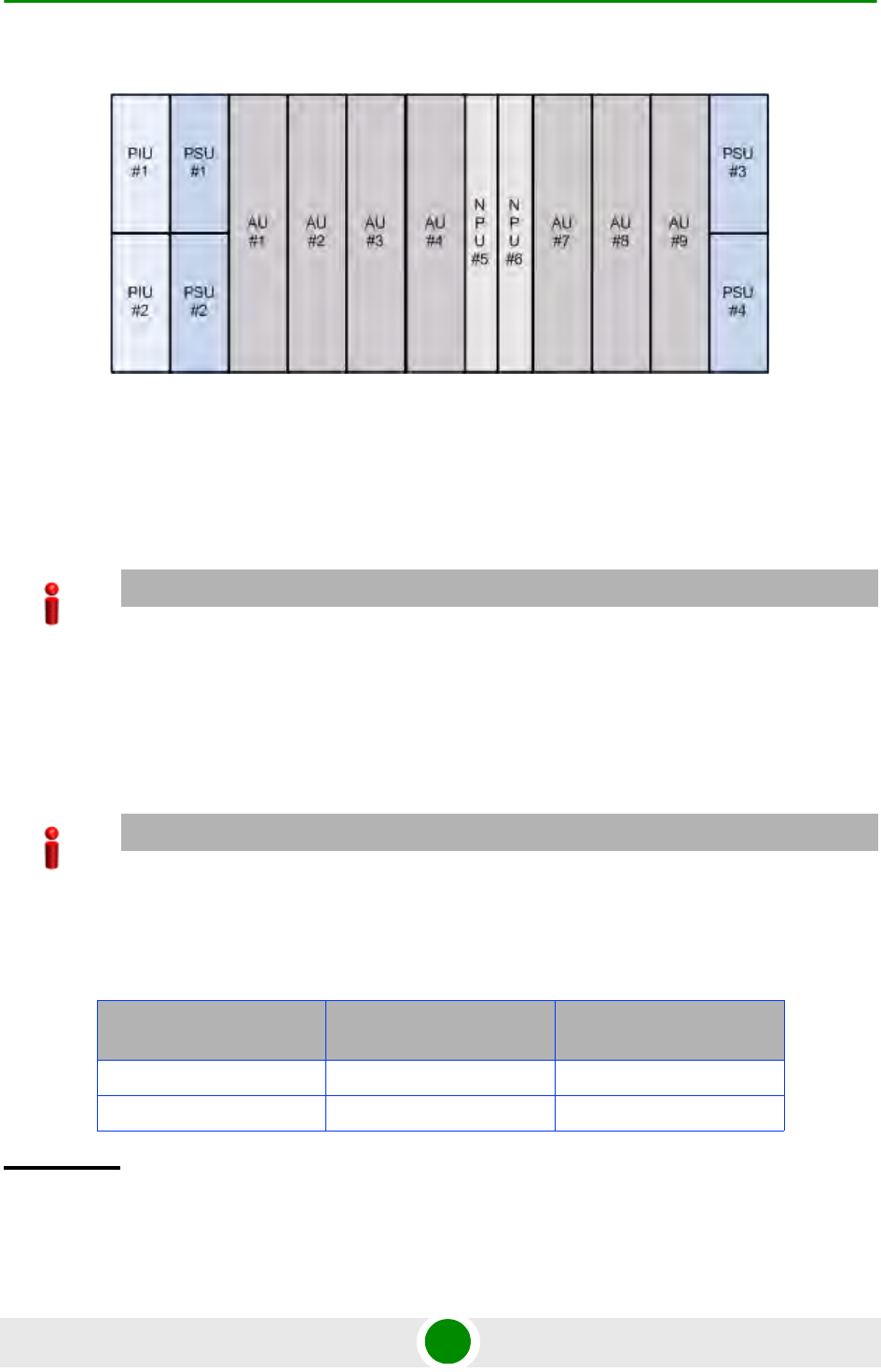
Chapter 4 - Operation and Administration Using the CLI NPU Configuration
4Motion 431 System Manual
Figure 4-1: Slot IDs of Shelf Components
For example, if you want to enable PSU, slot# 3, and disable the PIU, slot# 1, run
the following command:
npu(config)# enable PSU 3
npu(config)# disable PIU 1
Remember that a minimum AU-to-PSU/PIU ratio should always be maintained.
The following table lists the required active AU-to-PSU ratio. Before disabling the
PSU module, ensure that this ratio is maintained.
IMPORTANT
An error may occur if you specify a PSU slot ID that is not in the range, 1-4, or a PIU slot ID that is
not in the range 1-2.
IMPORTANT
Ensure that the NPU to PSU/PIU ratio is also maintained. At least one PSU and PIU should always
be active to support the NPU.
Table 4-24: Active AU-to-PSU Ratio
If the number of Active
AUs is... Number of active PSUs
should be... Number of Active PIU
1-4 2 1
5-7 3 1
Command
Syntax
npu(config)# enable {PSU | PIU} <slot id>
npu(config)# disable {PSU | PIU} <slot id>

Chapter 4 - Operation and Administration Using the CLI NPU Configuration
4Motion 432 System Manual
4.3.14.1.2 Configuring the PIU Hardware Version
You need to manually configure the PIU hardware version that is currently in use.
The system periodically checks whether the configured and actual hardware
versions are identical. If there is a difference in the configured and actual
versions, an alarm is raised.
To configure the PIU hardware version, run the following command:
npu(config)# PIU <slot id (1-2)> hw_version <version (0-7)>
Privilege
Level
10
Syntax
Description Parameter Description Presence Default
Value
Possible
Values
{PSU | PIU} Indicates whether the PSU or
PIU slot is to be enabled or
disabled.
Mandatory N/A PSU
PIU
<slot id> Indicates the slot ID of the
PSU/PIU that you want to
enable or disable. Refer
Figure 4-1 for more
information about the slot ID
assigned to each PIU/PSU
module on the 4Motion
chassis.
Mandatory N/A 1-4 for PSU
slot
1-2 for PIU
slot
Command
Modes
Global configuration mode
Command
Syntax
npu(config)# PIU <slot id (1-2)> hw_version <version (0-7)>
Privilege
Level
10

Chapter 4 - Operation and Administration Using the CLI NPU Configuration
4Motion 433 System Manual
4.3.14.2 Configuring the GPS
The GPS is used to synchronize the air link frames of Intra-site and Inter-site
located sectors to ensure that in all sectors the air frame will start at the same
time, and that all sectors will switch from transmit (downlink) to receive (uplink)
at the same time. This synchronization is necessary to prevent Intra-site and
Inter-site sectors interference. In addition, the GPS synchronizes frame numbers
that are transmitted by the AU.
The GPS clock generates a 1PPS signal with accuracy of 10-11 and maximum jitter
of 100ns, and is connected to the 4Motion shelf via the GPS SYNC IN connector on
the front panel of the NPU. The GPS clock requirements can be reached by an
outdoor installed GPS unit when it is synchronized to a minimum number of
(user-configurable) satellites.
This section describes the commands to be used for:
“Configuring the GPS Clocks” on page 434
“Configuring General Configuration Parameters for the GPS” on page 437
“Configuring the Date and Time” on page 439
“Configuring the Position” on page 440
Syntax
Description Parameter Description Presence Default
Value
Possible
Values
<slot id
(1-2)>
Indicates the PIU slot ID for
which the hardware version is
to be configured.
Mandatory N/A 1-2
hw_version
<version
(0-7)>
Indicates the hardware
version to be configured for
the PIU slot.
Mandatory N/A 0-7
Command
Modes
Global configuration mode
IMPORTANT
Implementation of GPS synchronization is based on the assumption that all sectors are operating with
the same frame size and with the same DL/UL ratio.

Chapter 4 - Operation and Administration Using the CLI NPU Configuration
4Motion 434 System Manual
“Configuring the Clock Mode” on page 441
“Configuring the Required Number of Satellites” on page 442
“Displaying GPS Clocks Parameters” on page 443
“Displaying GPS General Configuration Parameters” on page 444
“Displaying the Date and Time Parameters” on page 445
“Displaying the Position Parameters” on page 446
“Displaying the Clock Mode Parameter” on page 446
“Displaying the Number of Satellite Parameters” on page 447
4.3.14.2.1 Configuring the GPS Clocks
The GPS clock parameters determines the source for the main clocks in the
system. To configure the GPS clock, you are required to enable/disable:
External 1PPS: Determines the air-frame start time. Assuming that all systems
use the same air-frame size and DL/UL Ratio, then, when the 1PPS clock is
received from a GPS system, this mechanism ensures inter-site and intra-site
synchronization among all sectors, preventing cross interference and
saturation problems. When using the internal 1PPS clock (derived from the
selected 16 MHz clock source), only intra-site synchronization among sectors
can be achieved. You can either enable the external 1PPS clock source or use
the internal 1PPS clock source derived from the selected 16 MHz clock. By
default, the External IPPS clock is enabled. When using a GPS for
synchronization, the 1PPS clock is received from the GPS receiver and must be
enabled for proper operation.
IMPORTANT
Reset the system for changes in the GPS clock configuration to be applied to the entire system.

Chapter 4 - Operation and Administration Using the CLI NPU Configuration
4Motion 435 System Manual
External 16MHz: Generates all the main clocking signals in the system,
including the internal 1PPS clock. Using an external, accurate 16 MHz clock
source will enable better hold-over of the 1PPS clock upon temporary loss (or
reduced reliability when receiving less than 4 satellites) of the external 1PPS
clock. This will allow a longer time of continued operation before appearance of
interferences due to clock drifts among BSs. You can either enable the
external 16 MHz clock source or use the internal 16 MHz clock source. By
default, the external 16MHz clock is disabled. In the current release MHz clock
must be disabled.
To configure the GPS clock, run the following command:
npu(config)# set clock ([ External1PPS {Enable | Disable} ] [
External16MHz {Enable | Disable} ])
For example, to configure the internal 1PPS clock at the NPU to synchronize the
air frames for inter-site and intra-site sectors:
npu(config)# set clock External1PPS Disable
NOTE
If the external 1PPS GPS clock is enabled:
The concatenated slave NPU 16Mhz created from local 16MHz TCXO/OCXO at the NPU
provides holdover when the GPS loses synchronization with its satellites.
Configure the GPS parameters listed in section, Section 4.3.14.2.2.
Command
Syntax
npu(config)# set clock ([External1PPS {Enable | Disable}] [External16MHz
{Enable | Disable}])
Privilege
Level
10

Chapter 4 - Operation and Administration Using the CLI NPU Configuration
4Motion 436 System Manual
Syntax
Description Parameter Description Presence Default
Value
Possible
Values
External1PPS
{Enable |
Disable}
Indicates whether the
external 1PPS clock is
enabled or disabled.
If the External 1PPs clock is
enabled, synchronization of
air frames for inter-site and
intra-site sectors should be
managed by the external
1PPS GPS clock. If the
External 1PPS clock is
disabled, it indicates that the
internal 1PPS at the NPU is
used to synchronize air
frames for inter-site and
intra-site sectors.
When using a GPS, External
1PPS clock must be enabled
for proper operation of the
system.
Optional Enable Enable
Disable
External16MHz
{Enable |
Disable}
Indicates whether the
External 16Mhz clock is
enabled or disabled.
If the external 16 MHz is
enabled, the NPU should
receive 16Mhz signal from
the master NPU. This
parameter should be enabled
only if the NPU clock mode is
slave. If the NPU clock mode
is master, the MPU drives the
16Mhz signal towards the
slave NPUs.
In the current release
External 16MHz clock must
be disabled.
Optional Disable Enable
Disable
Command
Modes
Global configuration mode

Chapter 4 - Operation and Administration Using the CLI NPU Configuration
4Motion 437 System Manual
4.3.14.2.2 Configuring General Configuration Parameters for the GPS
The GPS general configuration parameters determine how the GPS should
function with respect to the 4Motion system. Depending upon the values defined
for these parameters, you can configure the GPS clock (external 1PPS and
16MHz), and the UTC time. Run the following command to configure the global
configuration parameters for the GPS:
npu(config)# gps config ( [Type {Trimble | None}] [AdaptorRequired
{Yes | No}][HoldoverPassedTout <expiry_interval(0-2880)>]
[HoldoverPassTxOperationStop {True | False}][AlmanacUsableTime
<expiry_interval(0-4320)>] [EphemerisUsableTime
<expiry_interval(0-168)>] [IntervalToReadGPSTime{Hourly | Daily |
Monthly | Yearly}] [TimeToReadGPSTime <HH:MM:SS,DD/MM>]))
IMPORTANT
Skip this section if you have selected the internal 1PPS clock. For more information about configuring
the GPS clock, refer Section 4.3.14.2.1.
IMPORTANT
An error may occur if:
Time to read GPS time is not in valid format. Correct format is hh:mm:ss, dd/mm: Minute and Second
should be within range of 0 to 60, Hour should be within the range of 0 to 23, days should be in the
range 1 to 31 and Month should be within the range of 1 to 12, also day should be valid in accodance
with month.
Command
Syntax
npu(config)# gps config gps config ( [Type {Trimble | None}]
[AdaptorRequired {Yes | No}][HoldoverPassedTout
<expiry_interval(0-2880)>] [HoldoverPassTxOperationStop {True |
False}][AlmanacUsableTime <expiry_interval(0-4320)>]
[EphemerisUsableTime <expiry_interval(0-168)>]
[IntervalToReadGPSTime{Hourly | Daily | Monthly | Yearly}]
[TimeToReadGPSTime <HH:MM:SS,DD/MM>]))
Privilege
Level
10
Syntax
Description
Parameter Description Presence Default
Value
Possible
Values

Chapter 4 - Operation and Administration Using the CLI NPU Configuration
4Motion 438 System Manual
Type {Trimble
| None}]
Indicates the type of GPS
connected to 4Motion.
Optional Trimble Trimble
None
[AdaptorRequ
ired {Yes |
No}]
Indicates whether a GPS
adaptor is required. The NPU
can be connected to an
extenal GPS adaptor that
allows the NPU to connect to
multiple GPS
interfaces/1PPS /16Mhz
clocks. In the current release
a GPS adapter is not
supported.
Optional No Yes
No
[HoldoverTimeo
ut
<expiry_interv
al (0-2880)>]
Indicates the period, in
minutes, for which the NPU
provides holdover when the
GPS loses synchronization
with its satellites.
Optional 720 0 - 2880
[HoldoverPassT
xOperationStop
{True |
False}]
Indicates whether the AU
modules should stop data
transmission if the GPS loses
synchronization with its
satellites and the holdover
timeout has occurred.
Optional True True
False
[AlmanacUsable
Time
<expiry-interv
al(0-4320)>]
Indicates the maximum
period, in hours, for which the
Almanac time is valid when
the GPS is reset.
Optional 720 0-4320
[EphemerisUsab
leTime
<expiry-interv
al(0-168)>]
Indicates the maximum
period, in hours, for which the
Ephemeris time is valid when
the GPS is reset.
Optional 4 0-168
[IntervalToRea
dGPSTime
{Hourly |
Daily |
Monthly |
Yearly}]
Indicates the interval after
which the NPU should obtain
the GPS time for frame
synchronization, and send it
to the AU.
Optional Daily Hourly
Daily
Monthly
Yearly
[TimeToReadGPS
Time
<HH:MM:SS,DD/M
M>]
Indicates the time when the
NPU should obtain the GPS
time for frame
synchronization. .
Optional 04:05 HH:MM:SS,DD
/MM

Chapter 4 - Operation and Administration Using the CLI NPU Configuration
4Motion 439 System Manual
4.3.14.2.3 Configuring the Date and Time
The UTC time is used to configure the following:
Local time: Differs from the UTC time with respect to the value you have
specified for the localUTCDiff and DST parameters. The local time is equal to
the sum of the UTC time, the value of the localUTCDiff parameter (local
offset from UTC time) and DST (daylight saving time offset). For more
information about configuring this parameter, “Configuring the GPS Clocks”
on page 434. You can use the CLI to display the current local time. For details,
refer the section, “Displaying the Date and Time Parameters” on page 445.
System time: Refers to the operating system (kernel) time that is identical to
the UTC time when the system boots up. The system time is updated every
hour with the time received from the GPS receiver.
Real Time Clock (RTC) time: Refers to the time maintained by the board’s
hardware clock. By default, the RTC time is set to 1st January, 1970. The RTC
time is updated every hour with the UTC time that is received from the GPS
receiver or that you have configured from the CLI. The RTC time is used for
creating the timestamp for log and trace messages, performance data
collection files, and for managing the interval after which a backup of the
configuration file should be maintained and performance data should be
collected.
Execute the following command to configure the date and time parameters. If the
GPS is synchronized to its satellites and is connected to 4Motion, the UTC time is
provided by the GPS. Otherwise the UTC time that you configure is used instead.
To configure the date and time parameters, run the following command:
npu(config)# set date [UTC <HH:MM:SS,DD/MM/YYYY>] [LocalUTCDiff
<+/-HH:MM>] [DST <(0-2)>]
Command
Modes
Global configuration mode
IMPORTANT
An error may occur if :
1) UTC time is not in the valid format i.e. hh: mm: ss, dd/mm/yyyy.
2) Local UTCDiff is not valid format i.e. +/-hh:mm
3) Local UTC Diff is out of the range between -12 to +13 or it is not in steps of 30 minutes.
4) DST is out of range i.e between 0 to 2

Chapter 4 - Operation and Administration Using the CLI NPU Configuration
4Motion 440 System Manual
4.3.14.2.4 Configuring the Position
The position configuration enables setting the location’s parameters when GPS is
not used (Type=None).
To configure the position parameters, run the following command:
npu(config)# set position ([Latitude <xxx.xxx,N/S>] [Longitude
<xxx.xxx,E/W>] [Altitude (-300.0 - 9000.0)])
Command
Syntax
npu(config)# set date [UTC <HH:MM:SS,DD/MM/YYYY>] [LocalUTCDiff
<+/-HH:MM>] [DST <(0-2)>]
Privilege
Level
10
Syntax
Description Parameter Description Presence Default
Value
Possible
Values
UTC
<HH:MM:SS,DD/M
M/YYYY>
Indicates the UTC time to be
used for 4Motion if not
available from GPS.
Mandatory N/A Use the format:
HH:MM: SS,
DD/MM/YYYY
LocalUTCDiff
<+/-HH:MM>
The local offset from UTC Optional +00:00 +/-HH:MM
HH: -12 to +13
MM: 00 or 30
DST <(0-2)> Daylight Saving Time offset of
the local clock
Optional 0 0-2
Command
Modes
Global configuration mode
IMPORTANT
An error may occur if :
1) Latitude, longitude and altitude are configured while GPS type is not "None".
2) Latitude is not in valid format i.e. lll.mmm,a where a is either N or S
3) Longitude is not in valid format i.e. lll.mmm,a where a is either E or W.
4) Altitude is not in valid range i.e. +-300.0 to 9000.0.

Chapter 4 - Operation and Administration Using the CLI NPU Configuration
4Motion 441 System Manual
4.3.14.2.5 Configuring the Clock Mode
The Clock Mode parameter enables defining the functionality of the NPU when
GPS chaining is used. In the current release GPS chaining is not supported and
the clock mode must be set to Master.
To configure the clock mode parameter, run the following command:
npu(config)# set npu ClockMode {Master | Redundant | Slave}
Command
Syntax
npu(config)# set position ([Latitude <xxx.xxx,N/S>] [Longitude
<xxx.xxx,E/W>] [Altitude (-300.0 - 9000.0)])
Privilege
Level
10
Syntax
Description Parameter Description Presence Default
Value
Possible
Values
Latitude
<xxx.xxx,N/S>
Indicates the latitude where
the 4Motion shelf is currently
positioned. Configure only if
GPS Type is None.
Optional 000.000.N Use the format,
Ill.mmm.a
(where lll.mmm
is in degrees
and the value
of a is either N
or S)
Longitude
<xxx.xxx,E/W>
Indicates the longitude where
the 4Motion shelf is currently
positioned. Configure only if
GPS Type is None.
Optional 000.000.E Use the format,
Ill.mmm.a
(where ll.mmm
is in degrees
and the value
of a is either E
or W)
Altitude
(-300.0 -
9000.0)])
Indicates the altitude (in
meters) where the 4Motion
shelf is currently positioned.
Configure only if GPS Type is
None.
Optional 0.0 -300.0 to
9000.0
Command
Modes
Global configuration mode

Chapter 4 - Operation and Administration Using the CLI NPU Configuration
4Motion 442 System Manual
4.3.14.2.6 Configuring the Required Number of Satellites
The satellite parameter enables configured the minimum number of satellites
required for maintaining synchronization and for renewing synchronization after
synchronization loss.
To configure the satellite parameters, run the following command:
npu(config)# set satellite ([MinNumOfSatForHoldoverReturn <range
(1-12)>] [MaxNumOfSatBeforeSyncLoss <range (0-11)>])
IMPORTANT
An error may occur if setting to any option other than Master because current release supports only
the Master option.
Command
Syntax
npu(config)# set npu ClockMode {Master | Redundant | Slave}
Privilege
Level
10
Syntax
Description Parameter Description Presence Default
Value
Possible
Values
npu ClockMode
{Master |
Redundant | Slave}
Indicates the clocks
functionality of the NPU when
GPS chaining is used. GPS
chaining is not supportyed in
current release and this
parameter must be set to its
default value of Master.
Optional Master Master
(other options
not supported
in current
release)
Command
Modes
Global configuration mode
IMPORTANT
1) An error can occur while configuring MinNumOfSatForHoldoverReturn if Minimum number of
satellite for holdover return is less than Maximum number of satellite before synchronization loss.
2) An error can occur while configuring MaxNumOfSatBeforeSyncLoss if Maximum number of
satellite before synchronization is more than Minimum number of satellite for holdover return.

Chapter 4 - Operation and Administration Using the CLI NPU Configuration
4Motion 443 System Manual
4.3.14.2.7 Displaying GPS Clocks Parameters
To display the GPS clock configuration parameters, run the following command:
npu# show clock status [{CurrentExternal1PPS |
ConfiguredExternal1PPS | CurrentExtrnal16MHz |
ConfiguredExternal16MHz}]
Command
Syntax
npu(config)# set satellite ([MinNumOfSatForHoldoverReturn <range (1-12)>]
[MaxNumOfSatBeforeSyncLoss <range (0-11)>]
Privilege
Level
10
Syntax
Description Parameter Description Presence Default
Value
Possible
Values
MinNumOfSatForH
oldoverReturn
<range (1-12)>
Indicates the minimum
number of satellites that
should be received for
resuming synchronization
(exiting holdover status) after
loss of synchronization.
Optional 2 1-12
MaxNumOfSatBef
oreSyncLoss
<range (0-11)>
Indicates the minimum
number of satellites required
for maintaining
synchronization.
Optional 1 0-11
Command
Modes
Global configuration mode
Command
Syntax
npu# show clock status [{CurrentExternal1PPS |
ConfiguredExternal1PPS | CurrentExtrnal16MHz |
ConfiguredExternal16MHz}
Privilege
Level
1

Chapter 4 - Operation and Administration Using the CLI NPU Configuration
4Motion 444 System Manual
4.3.14.2.8 Displaying GPS General Configuration Parameters
To display the GPS general configuration parameters, run the following command:
npu# show gps config [{ Type | SoftwareVersion [{ Navigation |
Signal }] | AdaptorRequired | HoldoverPassedTout |
HoldoverPassTxOperationStop | AlmanacUsableTime |
EphemerisUsableTime | IntervalToReadGPSTime | TimeToReadGPSTime} ]
Syntax
Description
For a detailed description of each parameter in this command, refer the section, “Configuring
the GPS Clocks” on page 434.
Both Current and Configured values for each clock are provided (the parameters are applied after
reset)
Display
Format
Configured External 1PPS Status :Enable/ Disable
Current External 1PPS Status :Enable/ Disable
Configured External 16MHz Status :Enable/ Disable
Current External 16MHz Status :Enable/ Disable
Command
Modes
Global command mode
Command
Syntax
npu# show gps config [{ Type | SoftwareVersion [{ Navigation | Signal }] |
AdaptorRequired | HoldoverPassedTout | HoldoverPassTxOperationStop |
AlmanacUsableTime | EphemerisUsableTime | IntervalToReadGPSTime |
TimeToReadGPSTime} ]
Privilege
Level
1
Syntax
Description
For a detailed description of each parameter in this command, refer the section, “Configuring
General Configuration Parameters for the GPS” on page 437.

Chapter 4 - Operation and Administration Using the CLI NPU Configuration
4Motion 445 System Manual
In addition to the configuration parameters, the SW Versions of the GPS
Navigation and Signal Processors are also displayed (if available).
4.3.14.2.9 Displaying the Date and Time Parameters
To display the current date parameters, run the following command:
npu# show date [{Local | UTC | LocalUTCDiff | DST}]
Display
Format
Configured GPS Type :
GPS Navigation Processor SW Version :
GPS Signal Processor SW version :
Adaptor Required :
Holdover Timeout :
HoldoverPassedTxOperationStop :
Almanac Usable Time :
Ephemeris Usable Time :
Interval To Read Gps Time :
Time To Read Gps Time :
Command
Modes
Global command mode
Command
Syntax
npu# show date [{Local | UTC | LocalUTCDiff | DST}]
Privilege
Level
1
Syntax
Description
For a detailed description of each parameter in this command, refer the section, “Configuring
the Date and Time” on page 439.
Display
Format
Local Time :
UTC Time :
Local UTC Offset :
Daylight Saving Time :

Chapter 4 - Operation and Administration Using the CLI NPU Configuration
4Motion 446 System Manual
In addition to the configurable parameters, the calculated Local Time is also
displayed.
4.3.14.2.10 Displaying the Position Parameters
To display the current position parameters, run the following command:
npu# show position [{Latitude | Longitude | Altitude}]
4.3.14.2.11 Displaying the Clock Mode Parameter
To display the current clock mode parameter, run the following command:
npu# show npu clock mode
Command
Modes
Global command mode
Command
Syntax
npu# show position [{Latitude | Longitude | Altitude}]
Privilege
Level
1
Syntax
Description
For a detailed description of each parameter in this command, refer the section, “Configuring
the Position” on page 440.
Display
Format
Latitude :
Longitude :
Altitude :
Command
Modes
Global command mode
Command
Syntax
npu# show npu clock mode
Privilege
Level
1

Chapter 4 - Operation and Administration Using the CLI NPU Configuration
4Motion 447 System Manual
4.3.14.2.12 Displaying the Number of Satellite Parameters
To display the current satellite parameters, run the following command:
npu# show satellite [{MinNumOfSatForHoldoverReturn |
MaxNumOfSatBeforeSyncLoss | NumOfSatelliteAvailable}]
In addition to the configurable parameters, the current number of satellites
acquired by the GPS receiver is also displayed.
4.3.14.3 Managing Power Feeders Configuration
The Power Feeder configuration enables specifying the AU port connected to each
Power Feeder port.
Syntax
Description
For a detailed description of the parameter in this command, refer the section, “Configuring the
Clock Mode” on page 441.
Display
Format
NPU Clock Mode : Master
Command
Modes
Global command mode
Command
Syntax
npu# show satellite [{MinNumOfSatForHoldoverReturn |
MaxNumOfSatBeforeSyncLoss | NumOfSatelliteAvailable}]
Privilege
Level
1
Syntax
Description
For a detailed description of each parameter in this command, refer the section, “Configuring
the Required Number of Satellites” on page 442.
Display
Format
Max Satellites Before Sync Loss :
Min Satellites For Holdover Return :
Number of Satellites Acquired :
Command
Modes
Global command mode

Chapter 4 - Operation and Administration Using the CLI NPU Configuration
4Motion 448 System Manual
4.3.14.3.1 Configuring Power Feeders
To configure the AU ports connected to the ports of a specific Power Feeder, run
the following command:
npu(config)# config pfUnitNo <pfunit no (1-4)> pfPortNo <pfport no
(1-4)> pfAuSlotNoDestination <AuslotNoDestination (-1,1-4,7-9)>
pfAuPortNoDestination <pfAuPortNoDestination (-1,1-4)>
Command
Syntax
npu(config)# config pfUnitNo <pfunit no (1-4)> pfPortNo <pfport no (1-4)>
pfAuSlotNoDestination <AuslotNoDestination (-1,1-4,7-9)>
pfAuPortNoDestination <pfAuPortNoDestination (-1,1-4)>
Privilege
Level
10
Syntax
Description Parameter Description Prese
nce
Default
Value
Possible
Values
pfUnitNo
<pfunit no
(1-4)>
The Power Feeder unit
number.
Mandatory N/A 1-4
pfPortNo
<pfport no
(1-4)>
Each combination
of Power Feeder
Unit Number and
Port Number can
appear in a
maximum of one
Power Feeder
instance
The Power Feeder port
number
Mandatory N/A 1-4
pfAuSlotNoDest
ination
<AuslotNoDesti
nation
(-1,1-4,7-9)>
The AU Slot number.
-1 means none.
Mandatory -1 (none) -1 (none), 1-4,
7-9

Chapter 4 - Operation and Administration Using the CLI NPU Configuration
4Motion 449 System Manual
4.3.14.3.2 Displaying Configuration Information for Power Feeders
To display configuration information for all defined Power Feeders, run the
following command:
npu# show power-feeder configuration
pfAuPortNoDest
ination
<pfAuPortNoDes
tination
(-1,1-4)>
Each combination
of AU Slot Number
and Port Number
can appear in a
maximum of one
Power Feeder
instance (excluding
combinations with
a none value).
The AU Port number.
-1 means none.
Mandatory -1 (none) -1 (none), 1-4
Command
Modes
Global configuration mode
Command
Syntax
npu# show power-feeder configuration
Privilege
Level
1
Display
Format (for
each
configured
instance)
PfUnitNo : <value>, PfPortNo : <value>, AuPortNo : <value>, AuSlotNo :
<value>
........
Command
Modes
Global command mode
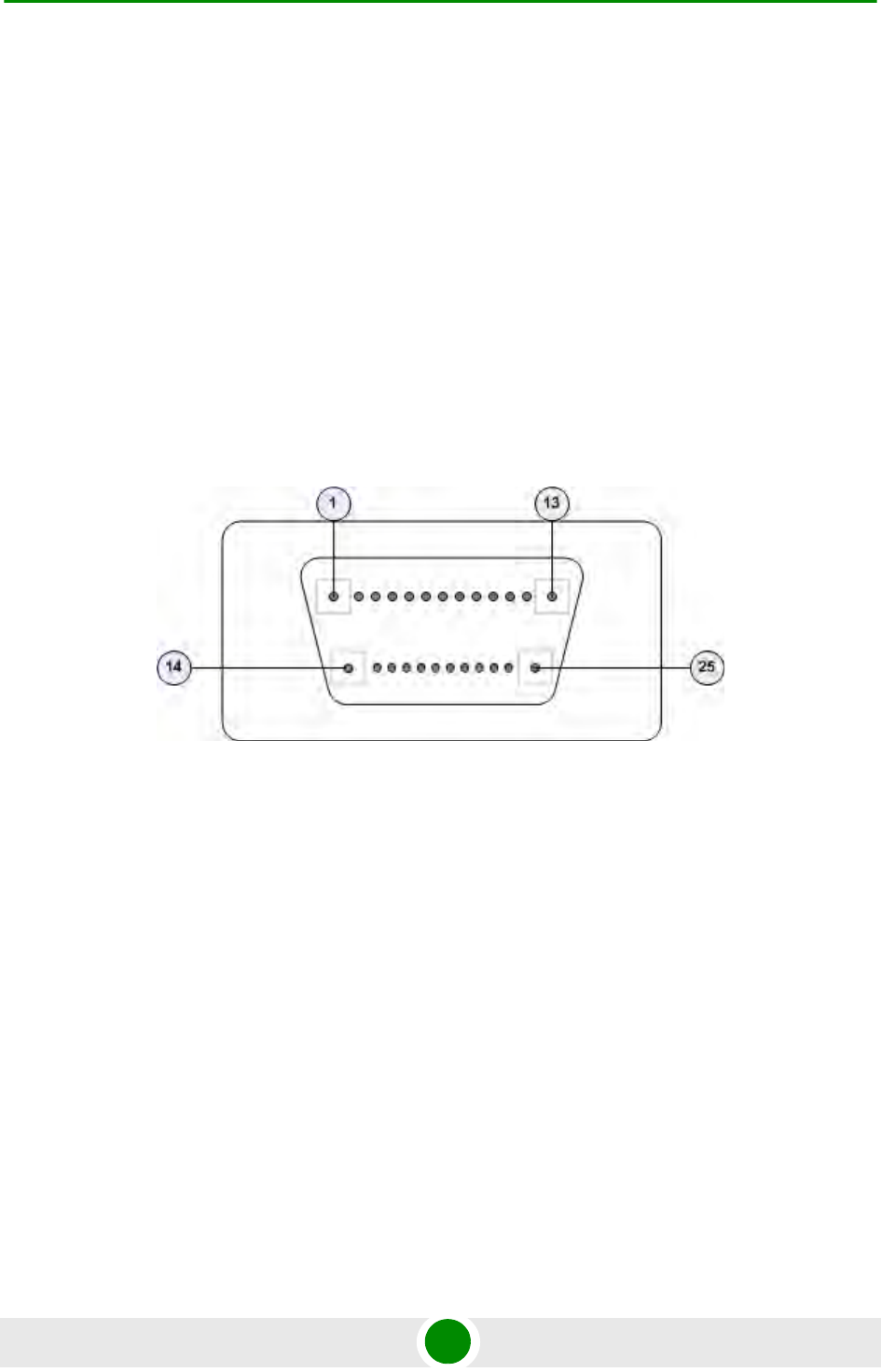
Chapter 4 - Operation and Administration Using the CLI NPU Configuration
4Motion 450 System Manual
4.3.14.4 Managing Dry-contact Input Alarms
Dry-contact input alarms are external devices that are connected to the 4Motion
unit, and notify the system when there is a change in external conditions. When
the system receives this notification, an SNMP trap is sent to the EMS. For
example, a device such as a temperature sensor that is connected to the 4Motion
unit, and configured to function as a dry-contact input alarm, can raise an alarm
to the system when there is a sudden change in the room temperature. The
system then sends an SNMP trap to the EMS, notifying the administrator of the
change indicated by the external device.
Dry contact input alarms are connected to the 4Motion system via a 25-pin micro
D-Type ALRM-IN/OUT connector on the NPU front panel. The following figure
depicts the ALRM-IN/OUT connector, and the pin numbers assigned to each pin:
Figure 4-2: 25-pin Micro D-Type ALRM-IN/OUT Connector
You can configure upto eight dry contact input alarms, each mapping to a
different pin number. This section describes the commands to be executed for:
“Mapping a Dry-contact Input Alarm to an Alarm Condition” on page 450
“Disabling Dry-contact Input Alarms” on page 454
4.3.14.4.1 Mapping a Dry-contact Input Alarm to an Alarm Condition
Dry contact alarms are connected to the 4Motion unit via the 25-pin micro D-Type
ALRM-IN/OUT connector on the front panel of the NPU. You can configure upto
eight dry contact input alarms, each connected to a different pin on the
ALRM-IN/OUT connector. Each alarm can then map to any of the following alarm
conditions. If the external dry-contact alarm detects that any of these conditions
is fulfilled, an alarm is raised, and a corresponding trap is sent to the EMS.

Chapter 4 - Operation and Administration Using the CLI NPU Configuration
4Motion 451 System Manual
Commercial power failure
Fire
Enclosure door open
High temperature
Flood
Low fuel
Low battery threshold
Generator failure
Intrusion detection
External equipment failure
To map the a dry contact alarm to an alarm condition, run the following
command:
npu(config)# dry-contact IN <alarm_num (1-8)> alarm
{CommercialPowerFailure | Fire | EnclosueDoorOpen | HighTemperature
| Flood | LowFuel | LowBatteryThreshold | GeneratorFailure |
IntrusionDetection | ExternalEquipmentFailure}
In this command, the alarm_num parameter maps to a pin on the ALRM IN-OUT
connector.
The following table lists the pin numbers of the 25-pin micro D-Type
ALRM-IN/OUT connector corresponding to the alarm number you are configuring:
IMPORTANT
Dry-contact input alarms are a means to raise a trap to the EMS when a change in conditions is
notified by the external device. However, the trap may not reach the EMS because of trap rate limiting,
network congestion or for reasons relating to the external equipment. Alvarion does not assume
responsiblity for traps that are lost.

Chapter 4 - Operation and Administration Using the CLI NPU Configuration
4Motion 452 System Manual
Refer Figure 4-2 for a diagrammatic representation of the 25-pin micro D-Type
ALRM-IN/OUT connector and the numbers assigned to each pin.
Table 4-25: Pin Numbers Corresponding to Dry Contact Input Alarm Numbers
Pin Number Alarm Number
3 and 15 1
4 and 16 2
5 and 17 3
6 and 18 4
7 and 19 5
8 and 20 6
9 and 21 7
10 and 22 8
NOTE
For more information about displaying the alarm conditions currently mapped to the micro D-Type
ALRM-IN/OUT connector pins, refer Section 4.3.14.6.
Command
Syntax
npu(config)# dry-contact IN <alarm_num (1-8)> alarm
{CommercialPowerFailure | Fire | EnclosueDoorOpen | HighTemperature |
Flood | LowFuel | LowBatteryThreshold | GeneratorFailure |
IntrusionDetection | ExternalEquipmentFailure}
Privilege
Level
10

Chapter 4 - Operation and Administration Using the CLI NPU Configuration
4Motion 453 System Manual
Syntax
Description Parameter Description Presence Default
Value
Possible
Values
<alarm_num
(1-8)>
Indicates the alarm number of
the dry contact input alarm
that is to be mapped to an
alarm condition. This alarm
number corresponds to a pin
on the 25-pin micro D-Type
jack .
For more information about
the pin numbers that
correspond to the alarm
number, refer Table 4-25.
Mandatory N/A 1-8

Chapter 4 - Operation and Administration Using the CLI NPU Configuration
4Motion 454 System Manual
4.3.14.4.2 Disabling Dry-contact Input Alarms
To disable a dry contact input alarm mapped to a specific alarm condition, run
the following command:
npu(config)# no dry-contact IN <alarm_num (1-8)>
alarm
{CommercialPow
erFailure |
Fire |
EnclosueDoorOp
en |
HighTemperatur
e | Flood |
LowFuel |
LowBatteryThre
shold |
GeneratorFailu
re |
IntrusionDetec
tion |
ExternalEquipm
entFailure
Indicates the alarm condition
to be mapped to a pin
number.
Mandatory N/A Commercial
PowerFailur
e
Fire
EnclosueDoo
rOpen
HighTempera
ture
Flood
LowFuel
LowBatteryT
hreshold
GeneratorFai
lure
IntrusionDete
ction
External
ExternalEqui
pmentFailur
e (can be
used for
defining a
condition
other than
the ones
specified by
the other
parameters
in this
command)
Command
Modes
Global configuration mode

Chapter 4 - Operation and Administration Using the CLI NPU Configuration
4Motion 455 System Manual
4.3.14.5 Managing Dry-contact Output Alarms
Dry-contact output alarms are raised by the system to notify an external device
connected to the 4Motion unit about a change in the system state. The external
monitoring entity may take the appropriate action after receiving the notification
from the 4Motion system.
You can use the CLI to raise an alarm to the external entity that is connected to
the dry contact output pin. After the system returns to its normal state, you can
clear the dry contact output alarm that you had raised.
Dry contact output alarms are connected to the 4Motion system via a 25-pin
micro D-Type ALRM-IN/OUT connector on the NPU front panel. The following
NOTE
For more information about mapping dry contact alarms to an alarm condition, refer to “Mapping
a Dry-contact Input Alarm to an Alarm Condition” on page 450. For more information
about displaying the alarm condition currently mapped to an alarm, refer to “Displaying
Configuration Information for Dry-contact Input/Output Alarms” on page 458.
Command
Syntax
npu(config)# no dry-contact IN <alarm_num (1-8)>
Privilege
Level
10
Syntax
Description Parameter Description Presence Default
Value
Possible
Values
<alarm_num
(1-8)>
Indicates the alarm number of
the dry contact input alarm
alarm that is to be disabled.
The value of this parameter
should be between 1 and 8.
For more information about
the pin numbers that
correspond to the alarm
number, refer Table 4-25.
Mandatory N/A 1-8
Command
Modes
Global configuration mode
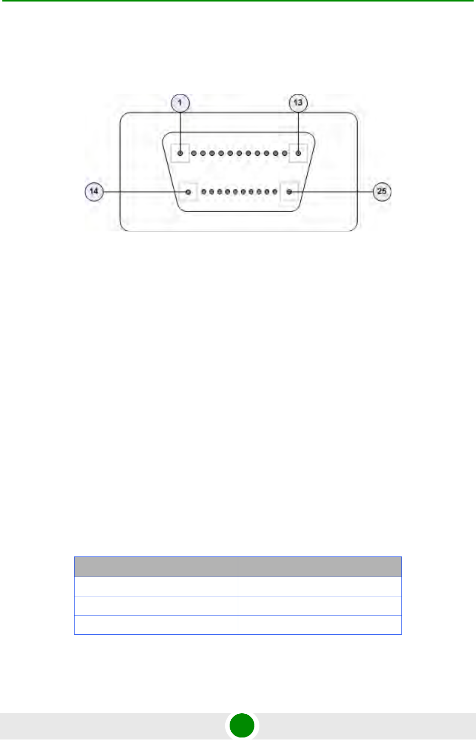
Chapter 4 - Operation and Administration Using the CLI NPU Configuration
4Motion 456 System Manual
figure depicts the ALRM-IN/OUT connector, and the pin numbers assigned to
each pin:
Figure 4-3: 25-pin Micro D-Type ALRM-IN/OUT Connector
You can configure upto three dry contact output alarms, each mapping to a
different pin number. This section describes the commands used for:
“Raising Dry-contact Output Alarms” on page 456
“Clearing Dry-contact Output Alarms” on page 457
4.3.14.5.1 Raising Dry-contact Output Alarms
You can raise a dry contact output alarm to any external entity that is connected
to the 4Motion unit via the 25-pin micro D-Type jack on the NPU front panel. To
raise a dry contact output alarm, run the following command:
npu(config)# dry-contact OUT <alarm_num (1-3)> alarm <alarm name >
In this command, the alarm_num parameter maps to a specific pin of the micro
D-Type ALRM-IN/OUT connector. The following table lists the pin numbers of the
25-pin micro D-Type ALRM-IN/OUT connector corresponding to the alarm
number you are configuring:
In this table, N.C denotes Not Closed, and N.O denotes Not Open.
Table 4-26: Pin Numbers Corresponding to Dry Contact Output Alarm Numbers
Pin Number Corresponding Alarm Number
1(FIX) - 2(N.C) - 14(N.O) 1
11(FIX)- 12(N.C) - 13(N.O) 2
23(FIX) - 24(N.C) - 25(N.O) 3

Chapter 4 - Operation and Administration Using the CLI NPU Configuration
4Motion 457 System Manual
Refer Figure 4-3 for a diagrammatic representation of the 25-pin micro D-Type
ALRM-IN/OUT connector and the numbers assigned to each pin.
4.3.14.5.2 Clearing Dry-contact Output Alarms
After the system returns to its normal state, run the following command to clear
the dry-contact output alarm that you had raised:
npu(config)# no dry-contact OUT <alarm_num (1-3)>
NOTE
After you have raised an alarm, clear this alarm when the system state returns to its normal
condition. For information, refer to, “Clearing Dry-contact Output Alarms” on page 457.
For more information about displaying configuration information about a dry contact output alarm,
refer to “Displaying Configuration Information for Dry-contact Input/Output
Alarms” on page 458.
Command
Syntax
npu(config)# dry-contact OUT <alarm_num (1-3)> alarm <alarm name >
Privilege
Level
10
Syntax
Description Parameter Description Presence Default
Value
Possible
Values
<alarm_num
(1-3)>
Indicates the alarm number of
the dry contact output alarm
that is to be configured. This
alarm number corresponds to
a pin on the 25-pin micro
D-Type jack .
For more information about
pin numbers that correspond
to the alarm number, refer
Table 4-26.
Mandatory N/A 1-3
alarm <alarm
name>
Indicates the name of the
dry-contact alarm to be
raised.
Mandatory N/A Up to 256
characters
Command
Modes
Global configuration mode

Chapter 4 - Operation and Administration Using the CLI NPU Configuration
4Motion 458 System Manual
After you run this command, the alarm that you had raised is cleared.
4.3.14.6 Displaying Configuration Information for Dry-contact
Input/Output Alarms
To display configuration information for dry-contact input/output alarms, run the
following command:
npu# show dry-contact {IN | OUT} [<alarm_num>]
If you want to display configuration information for input or output alarms,
specify IN or OUT. You can also specify the pin number if you want to view
configuration information for particular pin used for connecting an external device
to the 4Motion unit.
NOTENOTE
For more information about raising a dry contact ouput alarm, refer to “Raising Dry-contact
Output Alarms” on page 456.
Command
Syntax
npu(config)# no dry-contact OUT <alarm_num (1-3)>
Privilege
Level
10
Syntax
Description Parameter Description Presence Default
Value
Possible
Values
<alarm_num
(1-3)>
Indicates the alarm number of
the dry contact output alarm
alarm that is to be disabled.
For more information about
the pin numbers that
correspond to the alarm
number, refer Table 4-26.
Mandatory N/A 1-3
Command
Modes
Global configuration mode

Chapter 4 - Operation and Administration Using the CLI NPU Configuration
4Motion 459 System Manual
For example, run the following command if you want to display configuration
information for the dry contact input alarm connected to the 4Motion unit via
pin# 8 on the NPU panel:
npu# show dry-contact IN 8
If you want to display configuration information for all dry contact alarms, run the
following command:
npu# show dry-contact
NOTE
An error may occur if you have specified an incorrect pin number for a particular input/output alarm.
For more information about the correct pin-to-alarm number mapping, refer Table 4-25 and
Table 4-26.
Command
Syntax
npu# show dry-contact {IN | OUT} [<alarm_num>]
Privilege
Level
1
Syntax
Description Parameter Description Presence Default
Value
Possible
Values
{IN|OUT} Indicates whether
configuration information is to
be displayed for input or
output alarms. If you do not
specify this value,
configuration information is
displayed for all input and
output alarms.
Optional N/A IN
OUT

Chapter 4 - Operation and Administration Using the CLI NPU Configuration
4Motion 460 System Manual
4.3.14.7 Configuring the Location Information for the 4Motion Shelf
The site location parameters provide general information on the site. Run the
following command to configure the 4Motion shelf location information, such as
the rack number and location:
npu(config)# site {Name <name (32)> | Address <address(32)> |
RackLocation <rack no. + position in rack (32)> | ContactPerson
<name (32)> | AsnName <name (32)> |Region <area (32)> |ProductType
BMAX_4M_Macro}
For example, run the following command if you want to specify the site name:
npu(config)# site name Site 12
[<alarm_num>] Denotes the alarm number of
the input or output alarm for
which configuration
information is to be displayed.
Refer Figure 4-2 and
Figure 4-3 for more
information about the
numbers assigned to the pins
used for connecting dry
contact alarms.
Optional N/A 1-8 for input
alarms
1-3 for
output
alarms
Display
Format
Dry-Contact Input Alarm:
AlarmNumber AlarmName InputBlocking
<alarm num> <alarm name> <Yes or No>
Dry-Contact Output Alarm:
AlarmNumber AlarmStatus AlarmName
<alarm num> <On or Off> <name>
Command
Modes
Global command mode

Chapter 4 - Operation and Administration Using the CLI NPU Configuration
4Motion 461 System Manual
IMPORTANT
An error may occur if the length of any of these parameters exceeds the specified range. Refer the
syntax description for more information about the appropriate values and format for configuring
these parameters.
Command
Syntax
npu(config)# site (Name <name (32)> | Address <address(32)> |
RackLocation <rack no. + position in rack (32)> | ContactPerson <name
(32)> |AsnName <name (32)> |Region <area (32)> |ProductType
BMAX_4M_Macro)
Privilege
Level
10
Syntax
Description Parameter Description Presence Default
Value
Possible
Values
Name <name
(256)>}
Indicates the name of the
4Motion shelf.
Optional N/A String (up to 32
characters)
Address
<address
(256)>}
Indicates the address of the
4Motion site.
Optional N/A String (up to 32
characters)
RackLocation
<rack no. +
position in
rack (256)>}
Indicates the rack number
and location of the 4Motion
shelf.
Optional N/A String (up to 32
characters)
ContactPerson
<name (256)>
Indicates the name of person
who is administering the
4Motion shelf.
Optional String (up to 32
characters)
AsnName <name
(256)>
Indicates the name of the
Access Service Network for
which 4Motion is serving as
the ASN gateway.
Optional N/A String (up to 32
characters)
Region <area
(256)>
Indicates the region where
the site is located.
Optional N/A String (up to 32
characters)
ProductType
BMAX_4M_Macro
Indicates the product type. In
the current release it cannot
be changed from the default
of BMAX_4M_Macro
Optional BMAX_4
M_Macr
o
BMAX_4M_Ma
cro

Chapter 4 - Operation and Administration Using the CLI NPU Configuration
4Motion 462 System Manual
4.3.14.8 Configuring the Unique Identifier for the 4Motion Shelf
The Site Identifier (Site ID) is used by the management system as identifier of the
site and must be unique in the managed network.
The default value 0 is not a valid Site Identifier: it indicates that the Site Identifier
was not configured and a valid Site Identifier must be configured. A BTS with Site
Identifier 0 will not be discovered by AlvariSTAR.
Since the Site Identifier is used by AlvariSTAR to identify the site, it is highly
recommended not to modify it. If necessary, you must follow the Site Number
Change process described in the AlvariSTAR Device Manager User Manual.
To configure a unique identifier for the 4Motion shelf, run the following command:
npu(config)# site identifier <site id <0-999999>>
Command
Modes
Global configuration mode
NOTE
To display the 4Motion shelf identifer, refer to “Displaying the Unique Identifier for the
4Motion Shelf” on page 783.
Command
Syntax
npu(config)# site identifier <site id <0-999999>>
Privilege
Level
10
Syntax
Description Parameter Description Presence Default
Value
Possible
Values
<site id
<0-999999>>
Indicates the ID of the
4Motion shelf.
Mandatory N/A 0-999999
Command
Modes
Global configuration mode

Chapter 4 - Operation and Administration Using the CLI Managing MS in ASN-GW
4Motion 463 System Manual
4.4 Managing MS in ASN-GW
This section describes the MS level commands.
“Manual MS De-registration”
“Displaying MS Information”
4.4.1 Manual MS De-registration
Run the following command to initiate the de-registration process of the MS with
the specified NAI value or of all MSs.
npu(config)# de-reg ms {nai <nai-string> | all}
IMPORTANT
An error may occur if NAI value is not specified. Refer to the syntax description
for more information about the appropriate values and format for configuring
this parameter.
An error may occur also for “MS not found", in case no MS with the specified NAI
is registered at ASNGW.
Command
Syntax
npu(config)# de-reg ms {nai <nai-string> | all}
Privilege
Level
10
Syntax
Description Parameter Description Presence Default
Value
Possible
Values
de-reg ms {nai
<nai-string> |
all}
Initiates the de-registration of
the MS with the specified NAI
value.If “all” is specified then,
deregister all the MSs.
Mandatory N/A String
Command
Modes
Global configuration mode

Chapter 4 - Operation and Administration Using the CLI Managing MS in ASN-GW
4Motion 464 System Manual
4.4.2 Displaying MS Information
Run the following command to view the MS context information of the specified
NAI/MSID.
npu# show ms info [{nai|msid}<nai/msid string>]
IMPORTANT
An error may occur if invalid NAI or invalid MSID is provided. Refer the syntax
description for more information about the appropriate values and format for
configuring this parameter.
Command
Syntax
npu# show ms info [{nai|msid}<nai/msid string>]
Privilege
Level
1
Display
Format
MS context Info:
NAI = <value>
MS ID = <value>
Serving BS ID =
Serving Flow ID1 = <value>
Serving Flow GRE key = <value>
Serving Flow Direction = <Uplink | Downlink>
MS Flow Service Group IP = <value>|
Serving Flow IDn = <value>
Serving Flow GRE key = <value>
Serving Flow Direction = <Uplink | Downlink>
MS Flow Service Group IP = <value>
Command
Modes
Global command mode

Chapter 4 - Operation and Administration Using the CLI Managing AUs
4Motion 465 System Manual
4.5 Managing AUs
Up to seven AU objects can be created and configured, corresponding to the AU
cards that can be installed in slots 1-4, 7-9 of the shelf.
1Enable the AU configuration mode for the selected AU (refer to Section 4.5.1)
2You can now execute any of the following tasks:
»Configure one or more of the parameters tables of the AU (refer to
Section 4.5.2)
»Restore the default values of parameters in one or more of the parameters
tables of the AU (refer to Section 4.5.3)
3Terminate the AU configuration mode (refer to Section 4.5.4)
In addition, you can, at any time, display configuration and status information for
each of the parameters tables of the AU (refer to Section 4.5.6) or delete an
existing AU object (refer to Section 4.3.10.11.5).
4.5.1 Enabling the AU Configuration Mode\Creating
an AU Object
To configure the parameters of an AU, first enable the AU configuration mode for
the specific AU. Run the following command to enable the AU configuration mode.
You can also use this command to create a new AU object. A new AU object is
created with default values for all parameters.
npu (config)# au <(1 to 4 StepSize 1) | (7 to 9 StepSize 1)>
Specify the slot ID of the AU to be configured/created. See Figure 4-1 for slot
assignment in the shelf.
For example, to configure the AU in slot# 1, run the following command:
npu (config)# au 1
NOTE
In Release 2.0 up to 3 AUs may be used for service provisioning.
To configure an AU:

Chapter 4 - Operation and Administration Using the CLI Managing AUs
4Motion 466 System Manual
If you use this command to create a new AU, the configuration mode for this AU is
automatically enabled, after which you can execute any of the following tasks:
Configure one or more of the parameters tables of the AU (refer to
Section 4.5.2)
Restore the default values of parameters in one or more of the parameters
tables of the AU (refer to Section 4.5.3)
After executing the above tasks, you can terminate the AU configuration mode
(refer to Section 4.5.4) and return to the global configuration mode.
4.5.2 Configuring AU Parameters
After enabling the AU configuration mode you can configure the following
parameters tables:
IMPORTANT
An error occurs if you specify an AU slot ID that is not in the range, 1-4, or 7-9.
Command
Syntax
npu (config)# au <(1 to 4 StepSize 1) | (7 to 9 StepSize 1)>
Privilege
Level
10
Syntax
Description Parameter Description Presence Default
Value Possible
Values
<(1 to 4 StepSize
1) | (7 to 9
StepSize 1)>
The slot ID of the AU to be
configured
Mandatory N/A 1-4
7-9
Command
Modes
Global configuration mode
NOTE
The following examples are for au configuration mode for au-1 .

Chapter 4 - Operation and Administration Using the CLI Managing AUs
4Motion 467 System Manual
Properties (refer to Section 4.5.2.1)
Control (refer to Section 4.5.2.2)
Connectivity (refer to Section 4.5.2.3)
Reserved (refer to Section 4.5.2.4)
4.5.2.1 Configuring Properties
The properties table enables configuring the main properties of the required AU
card and controlling the power on each of the AU’s ODU ports.
To configure the properties parameters, run the following command:
npu(config-au-1)# properties [required-type {typeThree | typeTwo}]
[required-ports {four}] [required-bandwidth {fourteen | twenty | notrequired}]
[port-1-power {shutDown | noShutDown}] [port-2-power {shutDown |
noShutDown}] [port-3-power {shutDown | noShutDown | NA}] [port-4-power
{shutDown | noShutDown | NA}]
NOTE
You can display configuration information for the AU properties. For details, refer to
Section 4.5.6.1.
IMPORTANT
An error may occur if you provide an invalid value for any of these parameters. Refer the syntax
description for more information about the appropriate values and format for configuring these
parameters.
Command
Syntax
npu(config-au-1)# properties [required-type {typeThree | typeTwo}
] [required-ports {four} ] [required-bandwidth {fourteen | twenty
| notrequired} ] [port-1-power {shutDown | noShutDown} ]
[port-2-power {shutDown | noShutDown} ] [port-3-power {shutDown |
noShutDown | NA} ] [port-4-power {shutDown | noShutDown | NA} ]
Privilege
Level
10

Chapter 4 - Operation and Administration Using the CLI Managing AUs
4Motion 468 System Manual
Syntax
Description Parameter Description Presence Default
Value Possible
Values
[required-type
{typeThree |
ttypeTwo} ]
Defines the AU card
configuration required.
In the current release only
typeTwo AU is available.
Optional typeThree typeThree
typeTwo
[required-ports
{two | four} ]
Defines the No of AU card ODU
ports required.
In the current release only
four-ports AU is available.
Optional Four Four
[required-bandwi
dth {fourteen |
twenty |
notrequired} ]
Defines the AU card Bandwidth
(in MHz) required.
In the current release all cards
can support up to 20 MHz,
except to previous generation
cards that can support up to 14
MHz.
Optional Twenty Fourteen
Twenty
notrequired
[port-1-power
{shutDown |
noShutDown} ]
Controls power from AU card
port 1 to ODU
Optional No
Shutdown
shutDown
noShutDown
[port-2-power
{shutDown |
noShutDown} ]
Controls power from AU card
port 2 to ODU.
Optional No
Shutdown
shutDown
noShutDown
[port-3-power
{shutDown |
noShutDown |
NA} ]
Controls power from AU card
port 3 to ODU.
The NA (Not Applicable) option
is not relevant for a four-ports
AU.
Optional No
Shutdown
shutDown
noShutDown
NA
[port-4-power
{shutDown |
noShutDown |
NA} ]
Controls power from AU card
port 4 to ODU.
The NA (Not Applicable) option
is not relevant for a four-ports
AU.
Optional No
Shutdown
shutDown
noShutDown
NA
Command
Modes
au configuration mode

Chapter 4 - Operation and Administration Using the CLI Managing AUs
4Motion 469 System Manual
4.5.2.2 Configuring the Control Parameter
The control parameters enables controlling the operation of the AU.
To configure the control parameter, run the following command:
npu(config-au-1)# control shutdown-operation {normalOperation | reset |
shutdown}
4.5.2.3 Configuring Connectivity
The connectivity tables enables configuring the connectivity parameters for the
Ethernet interface of the AU. In the current release the interface operates in
802.1q mode: In this mode, the interface accepts only VLAN-tagged packets. All
packets received without VLAN tags are dropped.
To configure the connectivity parameters, run the following command:
npu(config-au-1)# connectivity [maxframesize <(1518 to 9000
StepSize 1)>] [bearervlanid <(0 to 4092 StepSize 1)>]
Command
Syntax
npu(config-au-1)# control shutdown-operation {normalOperation |
reset | shutdown}
Privilege
Level
10
Syntax
Description Parameter Description Presence Default
Value Possible Values
shutdown-operation
{normalOperation |
reset | shutdown}
Controls the
operation of the AU
card: Normal
Operation, Shutdown
(disable power to
card) or Reset.
Mandatory normal
Operation
normalOperation
reset
shutdown
Command
Modes
au configuration mode
Command
Syntax
npu (config-au-1)# connectivity [maxframesize <(1518 to 9000
StepSize 1)>] [bearervlanid <(0 to 4092 StepSize 1)>]

Chapter 4 - Operation and Administration Using the CLI Managing AUs
4Motion 470 System Manual
4.5.2.4 Configuring AU Reserved Parameters
As the name implies, the reserved parameters table enables configuring up to 9
parameters that are reserved for possible future use. In the current release none
of the reserved parameters is being used.
To configure the AU reserved parameters, run the following command:
Privilege
Level
10
Syntax
Description Parameter Description Presence Default
Value Possible
Values
[maxframesize
<(1518 to 9000
StepSize 1)>]
The maximum frame size (in
Bytes) that can be accepted
on the Ethernet interface of
the AU. Larger packets will be
dropped.
In 802.1q encapsulation
mode the actual minimal
frame size (including VLAN
tag) is 1522 bytes, which is
also the default.
Must be configured to the
same value as the mtu
parameter for this interface in
the NPU.
Optional 1522 1518 to 9000
[bearervlanid <(0
to 4092 StepSize
1)>]
The VLAN ID of packets on
the Ethernet interface of the
AU. It must be configured to
the same value as the if_vlan
parameter of the bearer
interface in the NPU.
Note that VLAN 10 is used for
internal management and
cannot be used the bearer
VLAN.
Optional 11 0-4092
Command
Modes
au-1 configuration mode

Chapter 4 - Operation and Administration Using the CLI Managing AUs
4Motion 471 System Manual
npu(config-au-1)# au-reserved [reserved-1 <string (32)>]
[reserved-2 <string (32)>] [reserved-3 <string (32)>] [reserved-4
<string (32)>] [reserved-5 <string (32)>] [reserved-6 <string
(32)>] [reserved-7 <string (32)>] [reserved-8 <string (32)>]
[reserved-9 <string (32)>]
4.5.3 Restoring Default Values for AU Configuration
Parameters
After enabling the AU configuration mode you can restore the default values for
parameters in the following parameters tables:
Properties (refer to Section 4.5.3.1)
Control (refer to Section 4.5.3.2)
Connectivity (refer to Section 4.5.3.3)
Reserved (refer to Section 4.5.3.4)
Command
Syntax
npu (config-au-1)# au-reserved [reserved-1 <string (32)>]
[reserved-2 <string (32)>] [reserved-3 <string (32)>] [reserved-4
<string (32)>] [reserved-5 <string (32)>] [reserved-6 <string
(32)>] [reserved-7 <string (32)>] [reserved-8 <string (32)>]
[reserved-9 <string (32)>]
Privilege
Level
10
Syntax
Description Parameter Description Presence Default
Value Possible
Values
[reserved-N <string
(32)>] (N=1-9)
Reserved parameter number
N
Optional null (an
empty
string)
A string of 32
printable
characters.
Command
Modes
au configuration mode

Chapter 4 - Operation and Administration Using the CLI Managing AUs
4Motion 472 System Manual
4.5.3.1 Restoring the Default Values of Properties Parameters
To restore the some or all of the Properties parameters to their default value, run
the following command:
npu(config-au-1)# no properties [required-type] [required-ports]
[required-bandwidth] [port-1-power] [port-2-power] [port-3-power]
[port-4-power]
You can restore only selected parameters to their default value by specifying only
those parameter. For example, to restore only the required type to the default
value (threeDSP), run the following command:
npu(config-au-1)# no properties required-type
The parameter will be restored to its default value, while the other parameters will
remain unchanged.
To restore all properties parameters to their default value, run the following
command:
npu(config-au-1)# no properties
4.5.3.2 Restoring the Default Value of the Control Parameter
To restore the Control parameter to the default value (normalOperation), run the
following command:
npu(config-au-1)# no control
NOTE
Refer to Section 4.5.2.1 for a description and default values of these parameters.
Command
Syntax
npu(config-au-1)# no properties [required-type] [required-ports]
[required-bandwidth] [port-1-power] [port-2-power] [port-3-power]
[port-4-power]
Privilege
Level
10
Command
Modes
au configuration mode

Chapter 4 - Operation and Administration Using the CLI Managing AUs
4Motion 473 System Manual
4.5.3.3 Restoring the Default Values of Connectivity Parameters
To restore Connectivity parameters do their default value, run the following
command:
npu(config-au-1)# no connectivity [maxframesize] [bearervlanid]
You can restore only one of the parameters to its default value by specifying only
that parameter. For example, to restore only the maximum frame size to the
default (1522), run the following command:
npu(config-au-1)# no connectivity maxframesize
The maximum frame size will be restored to its default value, while the
bearervlanid parameter will remain unchanged.
To restore both parameters to their default value, run the following command:
npu(config-au-1)# no connectivity
Command
Syntax
npu(config-au-1)# no control
Privilege
Level
10
Command
Modes
Global configuration mode
NOTE
Refer to Section 4.5.2.3 for a description and default values of these parameters.
Command
Syntax
npu(config-au-1)# no connectivity [maxframesize] [bearervlanid]
Privilege
Level
10
Command
Modes
au configuration mode

Chapter 4 - Operation and Administration Using the CLI Managing AUs
4Motion 474 System Manual
4.5.3.4 Restoring the Default Values of AU Reserved Parameters
To restore the AU Reserved parameters to their default value, run the following
command:
npu(config-au-1)# no au-reserved [reserved-1] [reserved-2]
[reserved-3] [reserved-4] [reserved-5] [reserved-6] [reserved-7]
[reserved-8] [reserved-9]
You can restore only selected parameters to their default value by specifying only
those parameter. For example, to restore only the reserved-1 parameter to its
default values, run the following command:
npu(config-au-1)# no au-reserved reserved-1
This parameter will be restored to the default value, while the other parameters
will remain unchanged.
To restore all parameters to their default value, run the following command:
npu(config-au-1)# no au-reserved
4.5.4 Terminating the AU Configuration Mode
Run the following command to terminate the au configuration mode:
npu(config-au-1)# exit
NOTE
Refer to Section 4.5.2.4 for a description and default values of these parameters.
Command
Syntax
npu(config-au-1)# no au-reserved [reserved-1] [reserved-2]
[reserved-3] [reserved-4] [reserved-5] [reserved-6] [reserved-7]
[reserved-8] [reserved-9]
Privilege
Level
10
Command
Modes
Global configuration mode
Command
Syntax
npu(config-au-1)# exit

Chapter 4 - Operation and Administration Using the CLI Managing AUs
4Motion 475 System Manual
4.5.5 Deleting an AU Object
Run the following command to delete an AU object:
npu(config)# no au <(1 to 4 StepSize 1) | (7 to 9 StepSize 1)>
4.5.6 Displaying Configuration and Status
Information for AU Parameters
You can display the current configuration and (where applicable) additional status
information for the following parameters tables:
Properties (refer to Section 4.5.6.1)
Privilege
Level
10
Command
Modes
au-1 configuration mode
IMPORTANT
An associated AU (specified in a Sector Association) cannot be deleted.
Command
Syntax
npu(config)# no au <(1 to 4 StepSize 1) | (7 to 9 StepSize 1)>
Privilege
Level
10
Syntax
Description Parameter Description Presence Default
Value
Possible
Values
<(1 to 4 StepSize 1) |
(7 to 9 StepSize 1)>
The slot ID of the AU card Mandatory N/A 1-4, 7-9
Command
Modes
Global configuration mode

Chapter 4 - Operation and Administration Using the CLI Managing AUs
4Motion 476 System Manual
Control (refer to Section 4.5.6.2)
Connectivity (refer to Section 4.5.6.3)
Reserved (refer to Section 4.5.6.4)
4.5.6.1 Displaying Configuration and Status Information for AU
Properties
To display configuration and status information for the properties of a specific or
all AU objects, run the following command:
npu# show properties au [<(1 to 4 StepSize 1) | (7 to 9 StepSize 1)>]
Specify the au slot ID (1-4, 7-9) if you want to display configuration and status
information for a particular AU. Do not specify a value for this parameter if you
want to view configuration and status information for all existing AU objects.
Command
Syntax
npu# show properties au [<(1 to 4 StepSize 1) | (7 to 9 StepSize 1)>]
Privilege
Level
1
Syntax
Description Parameter Description Presence Default
Value
Possible
Values
[<(1 to 4 StepSize 1) | (7
to 9 StepSize 1)>]
The slot ID of the AU
Specify a value for this
parameter if you want to
display the properties of a
specific AU. Do not specify a
value for this parameter if you
want to display the properties
of all AUs.
Optional N/A 1-4, 7-9

Chapter 4 - Operation and Administration Using the CLI Managing AUs
4Motion 477 System Manual
In addition to the configurable parameters, the following status parameters are
also displayed:
Display
Format
(for each
existing AU
object if
requested
for all AUs)
SlotNo. :<value>
RequiredType :<value>
RequiredPorts :<value>
RequiredBandwidth(MHz) :<value>
InstalledStatus :<value>
InstalledType :<value> (0 for notinstalled AU)
InstalledPorts :<value> (0 for notinstalled AU)
InstalledBandwidth(MHz) :<value> (0 for notinstalled AU)
HWVersion :<value> (null for notinstalled AU)
HWRevision :<value> (null for notinstalled AU)
SerialNo. :<value> (null for notinstalled AU)
BootVersion :<value> (null for notinstalled AU)
IFVersion :<value> (null for notinstalled AU)
IFRevision :<value> (null for notinstalled AU)
Port1PowertoODU :<value>
Port2PowertoODU :<value>
Port3PowertoODU :<value>
Port4PowertoODU :<value>
Command
Modes
Global command mode
Parameter Description Possible Values
InstalledStatus Indicates whether an AU card is
installed in the slot.
Following parameters are
applicable only for installed AU.
installed (1)
notinstalled (0)

Chapter 4 - Operation and Administration Using the CLI Managing AUs
4Motion 478 System Manual
4.5.6.2 Displaying Configuration for AU Control
To display configuration for the Control parameter of a specific or all AU objects,
run the following command:
npu# show control au [<(1 to 4 StepSize 1) | (7 to 9 StepSize 1)>]
Specify the au slot ID (1-4, 7-9) if you want to display configuration information
for a particular AU. Do not specify a value for this parameter if you want to view
configuration information for all existing AU objects.
InstalledType The AU Type. threeDSP (1)
twoDSP (2)
other (3)
auNotDetected (4)
InstalledPorts The number of ODU ports. two (1)
four (2)
other (3)
auNotDetected (4)
InstalledBandwidth(MHz) The bandwidth supported by the
AU.
fourteen (1)
twenty (2)
other (3)
auNotDetected (4)
HWVersion AU HW Version number <number>
HWRevision AU HW Revision number <number>
SerialNo. AU Serial number <number>
BootVersion AU Boot SW Version number <string>
IFVersion AU IF Version number <number>
IFRevision AU HW Revision number <number>
Command
Syntax
npu# show control au [<(1 to 4 StepSize 1) | (7 to 9 StepSize 1)>]
Privilege
Level
1
Parameter Description Possible Values

Chapter 4 - Operation and Administration Using the CLI Managing AUs
4Motion 479 System Manual
4.5.6.3 Displaying Configuration Information for AU Connectivity
Parameters
To display configuration information for the connectivity parameters of a specific
or all AU objects, run the following command:
npu# show connectivity au [<(1 to 4 StepSize 1) | (7 to 9 StepSize 1)>]
Specify the au slot ID (1-4, 7-9) if you want to display configuration for a
particular AU. Do not specify a value for this parameter if you want to view
configuration for all existing AU objects.
The displayed information includes also configured values for relevant parameters
that are configured for the internal management interface of the NPU.
Syntax
Description Parameter Description Presence Default
Value
Possible
Values
[<(1 to 4 StepSize 1) | (7
to 9 StepSize 1)>]
The slot ID of the AU
Specify a value for this
parameter if you want to
display the control parameter
of a specific AU. Do not
specify a value for this
parameter if you want to
display the control
parameters of all AUs.
Optional N/A 1-4, 7-9
Display
Format
(for each
existing AU
object if
requested
for all AUs)
SlotNo. :<value>
AUPowerControl :<value>
Command
Modes
Global command mode
Command
Syntax
npu# show connectivity au [<(1 to 4 StepSize 1) | (7 to 9 StepSize 1)>]

Chapter 4 - Operation and Administration Using the CLI Managing AUs
4Motion 480 System Manual
In addition to the configurable parameters, the following status parameters are
also displayed:
Privilege
Level
1
Syntax
Description Parameter Description Presence Default
Value
Possible
Values
[<(1 to 4 StepSize 1) | (7
to 9 StepSize 1)>]
The slot ID of the AU
Specify a value for this
parameter if you want to
display the connectivity
parameters of a specific AU.
Do not specify a value for this
parameter if you want to
display the connectivity
parameters of all AUs.
Optional N/A 1-4, 7-9
Display
Format
(for each
existing AU
object if
requested
for all AUs)
SlotNo. :<value>
EncapsulationMode :vlanAwareBridging(0)
MaxFrameSize(Bytes) :<value>
InternalManagementVLANID :<value>
BearerVLANID :<value>
InternalManagementIPAddress :<value>
InternalManagementIPSubnetMask :<value>
Command
Modes
Global command mode
Parameter Description Possible Values
EncapsulationMode The Ethernet encapsulation
mode of the card’s Ethernet port
(hard coded in production).
vlanAwareBridging(0)
InternalManagementVLANID The VLAN ID Management of
the shelf.(hard coded in
production)
0-4092

Chapter 4 - Operation and Administration Using the CLI Managing AUs
4Motion 481 System Manual
4.5.6.4 Displaying Configuration Information for AU Reserved
Parameters
To display configuration information for the reserved parameters of a specific or
all AU objects, run the following command:
npu# show au-reserved au [<(1 to 4 StepSize 1) | (7 to 9 StepSize 1)>]
Specify the au slot ID (1-4, 7-9) if you want to display configuration for a
particular AU. Do not specify a value for this parameter if you want to view
configuration for all existing AU objects.
InternalManagementIPAddress IP Address of the
internainterface of the AU.
Acquired via DHCP.
IP address
InternalManagementIPSubnetMask Subnet Mask of the
internainterface of the AU.
Acquired via DHCP.
Subnet mask
Command
Syntax
npu# show au-reserved au [<(1 to 4 StepSize 1) | (7 to 9 StepSize 1)>]
Privilege
Level
1
Syntax
Description Parameter Description Presence Default
Value
Possible
Values
[<(1 to 4 StepSize 1) | (7
to 9 StepSize 1)>]
The slot ID of the AU
Specify a value for this
parameter if you want to
display the reserved
parameters of a specific AU.
Do not specify a value for this
parameter if you want to
display the reserved
parameters of all AUs.
Optional N/A 1-4, 7-9