Alvarion Technologies BMAX-OR-25 BreezeMax 4Motion Broadband Wireless System User Manual 4Motion System Manual
Alvarion Technologies Ltd. BreezeMax 4Motion Broadband Wireless System 4Motion System Manual
Contents
- 1. Manual 1
- 2. Manual 2
- 3. Manual 3
- 4. Manual 4
- 5. Manual
Manual 2

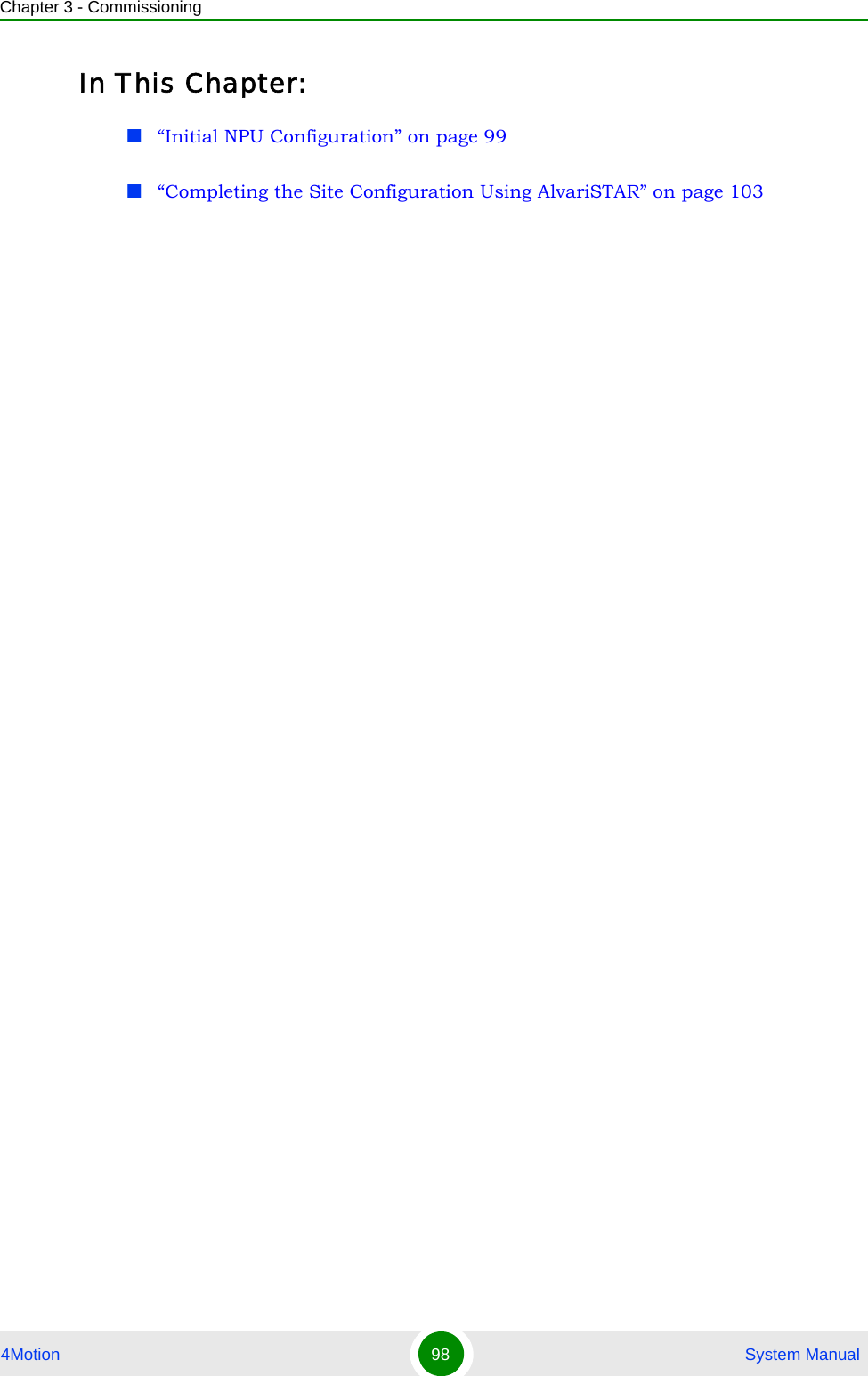
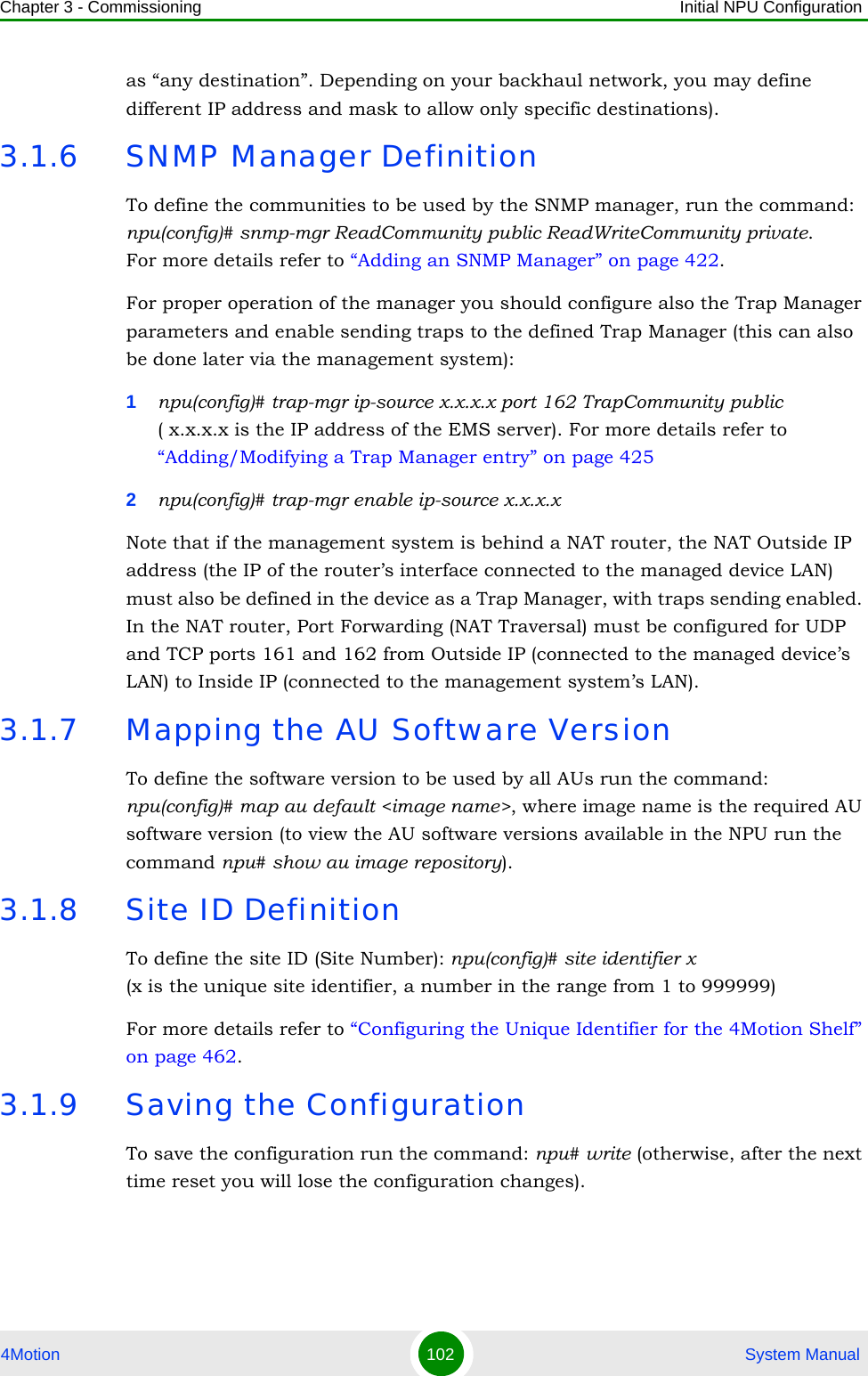
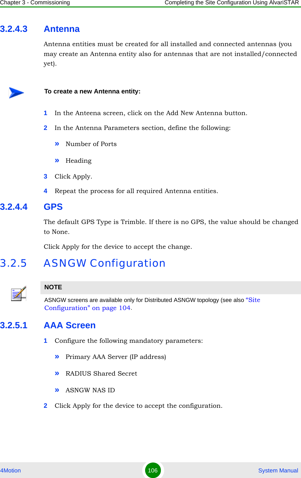
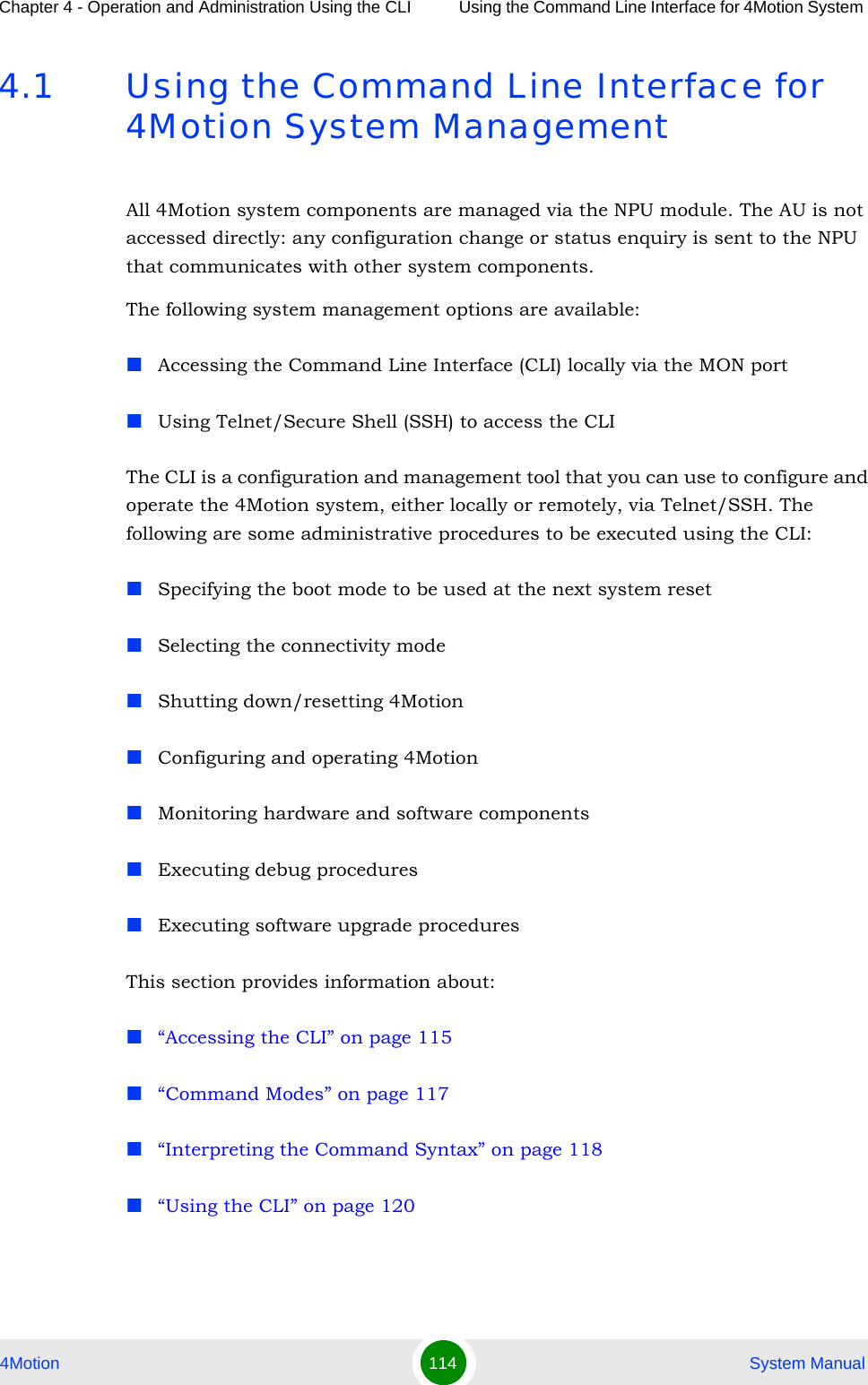
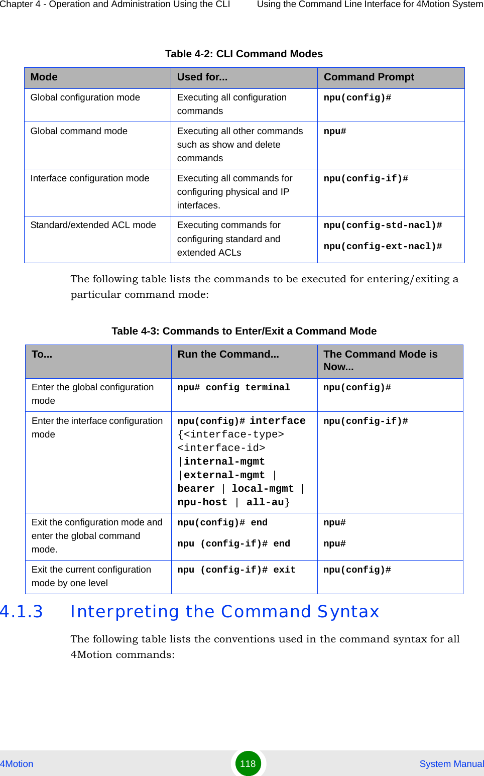
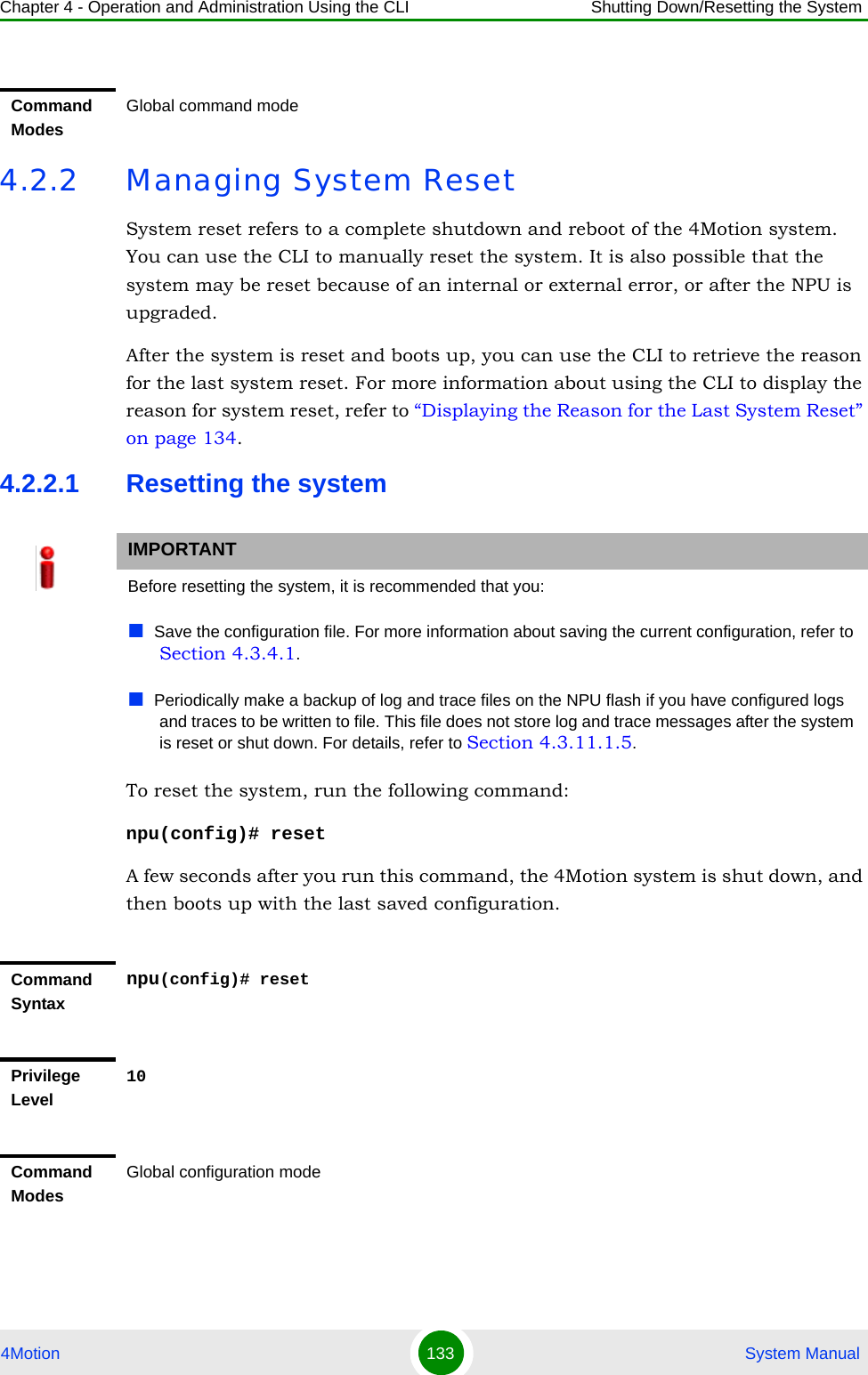
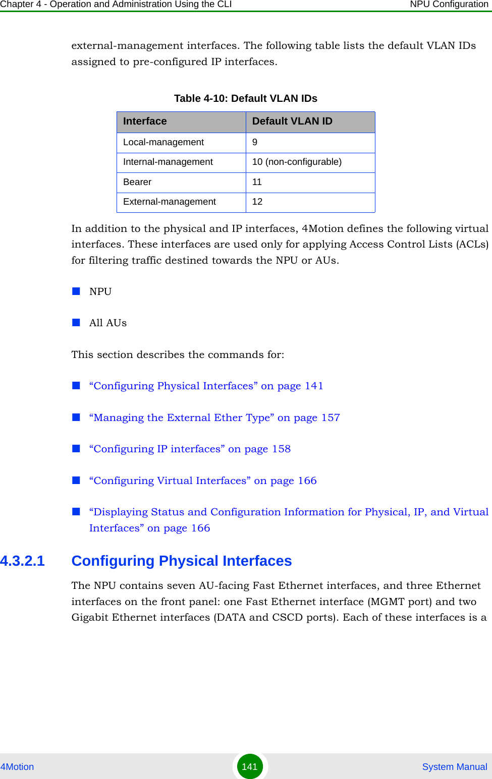
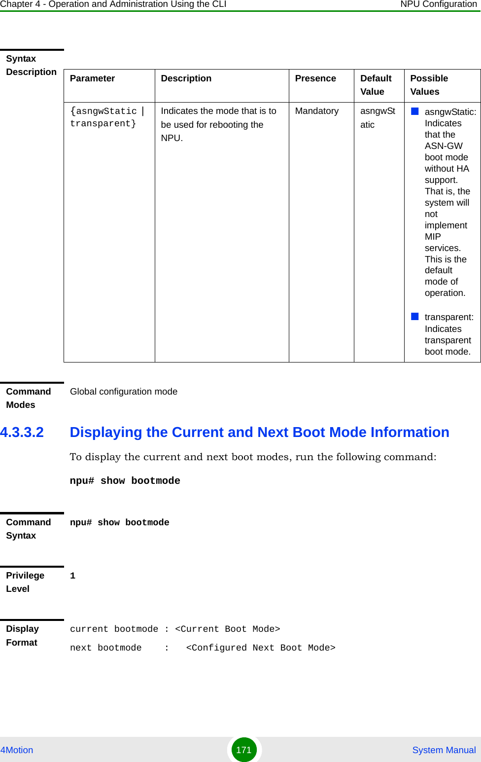
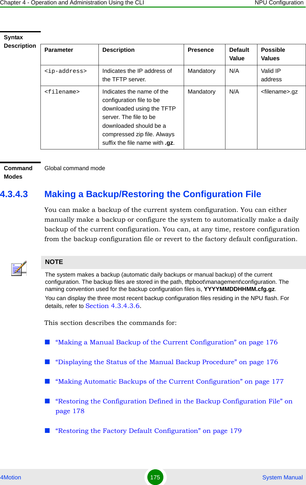
![Chapter 4 - Operation and Administration Using the CLI Using the Command Line Interface for 4Motion System 4Motion 119 System ManualTable 4-4: Conventions Used in the 4Motion Command SyntaxConvention Description Example{ } Indicates that the parameters enclosed in these brackets are mandatory, and only one of these parameters should be specified.npu(config)# limit { cpu | memory} ([softlimit <limit>] [hardlimit <limit>])This command is used for specifying the soft and hard limits for memory and CPU utilization. The cpu/memory parameters are enclosed within {} brackets, indicating that their presence is mandatory, and that only one of these parameters is required. ( ) Indicates that one or all parameters enclosed within these brackets are optional. However, the presence of at least one parameter is required to successfully execute this command.npu(config)# limit { cpu | memory} ([softlimit <limit>] [hardlimit <limit>])This command is used for specifying the soft and hard limits for memory and CPU utilization. The softlimit and hardlimit parameters are enclosed within () brackets, indicating that you are required to specify the value of at least one of these parameters to successfully execute this command.[ ] Indicates that the parameter enclosed within these brackets is optional.npu(config)# reboot from shadow [<shadow image name>]This command is used to reboot the system with the shadow image. The shadow image name parameter is enclosed with the [ ] brackets, indicating that it is optional. If you do not specify the value of this parameter, the system automatically boots up with the last downloaded shadow image.< > Indicates that the parameter is mandatory and requires a user-defined value (and not a discrete value).npu(config)# load to shadow <shadow image name>This command is used to load the system with a particular shadow image. It is mandatory to specify a value for the shadow image name parameter; otherwise an error is raised by the system. The value of this parameter is not a discrete value; you are required to specify a value for this parameter.](https://usermanual.wiki/Alvarion-Technologies/BMAX-OR-25.Manual-2/User-Guide-1114030-Page-23.png)
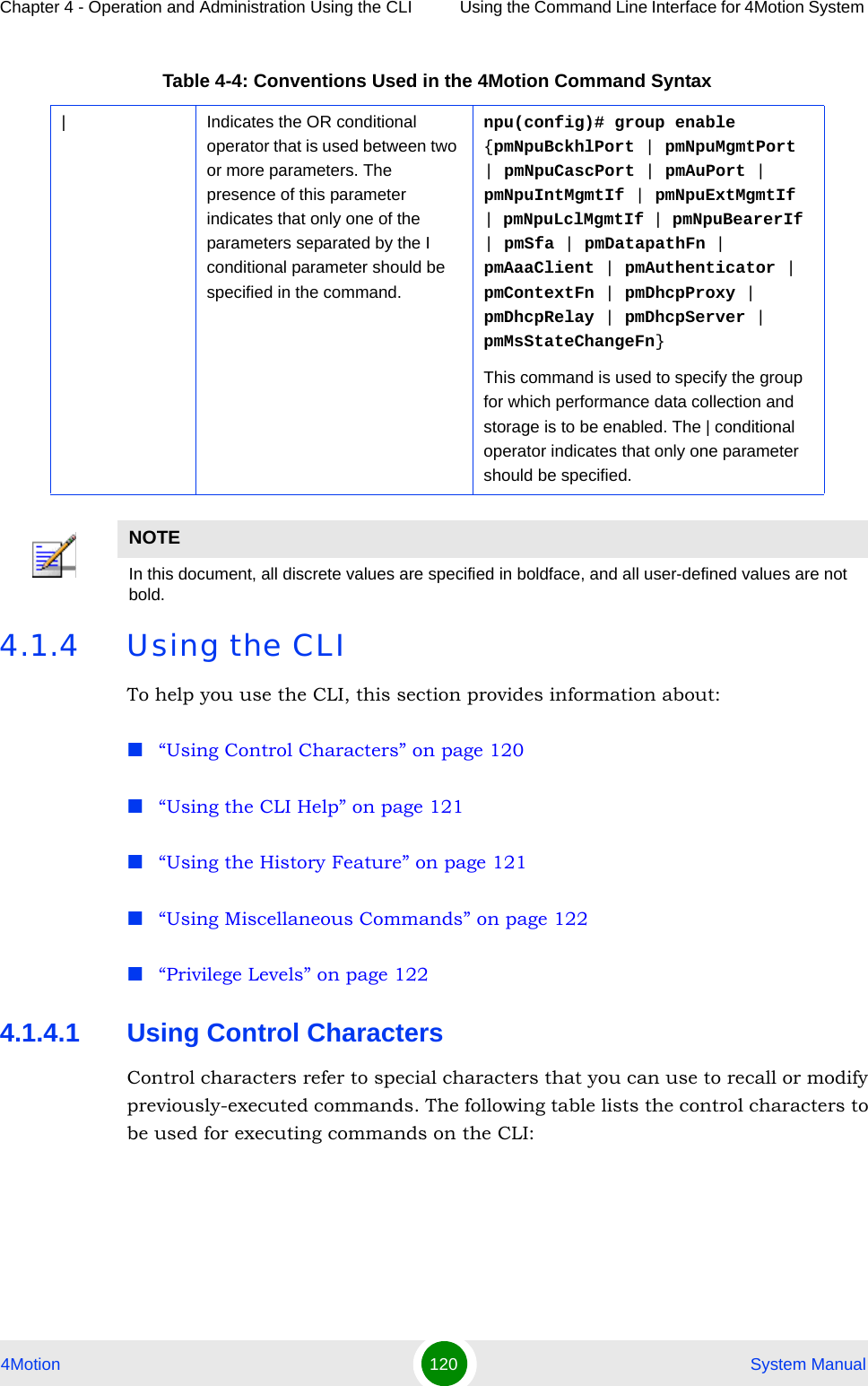
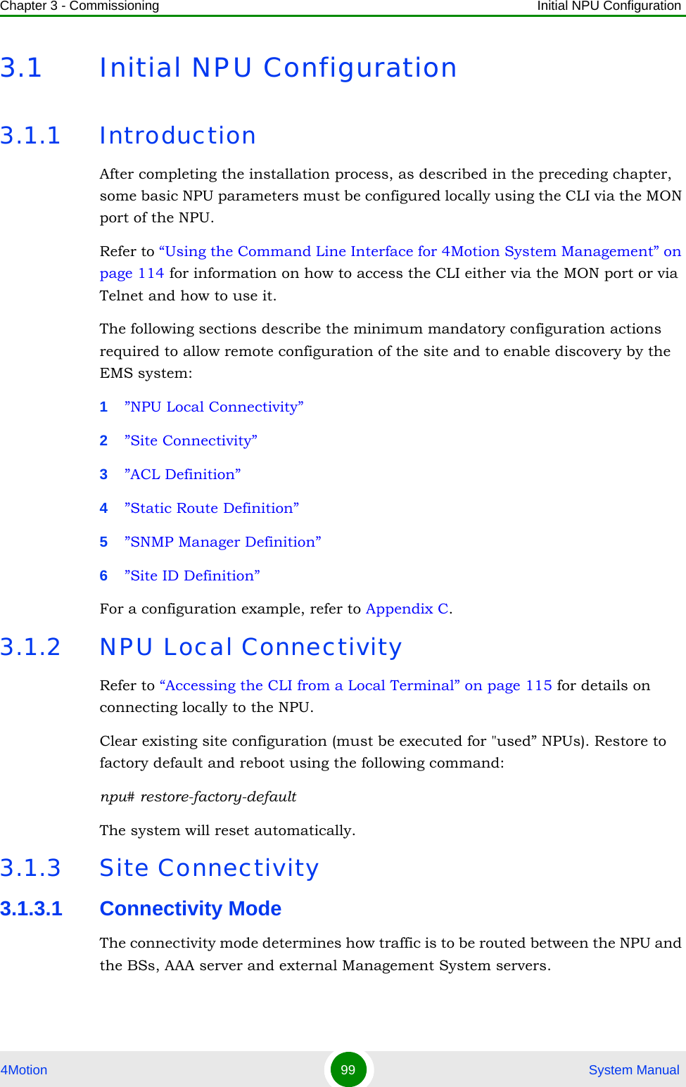
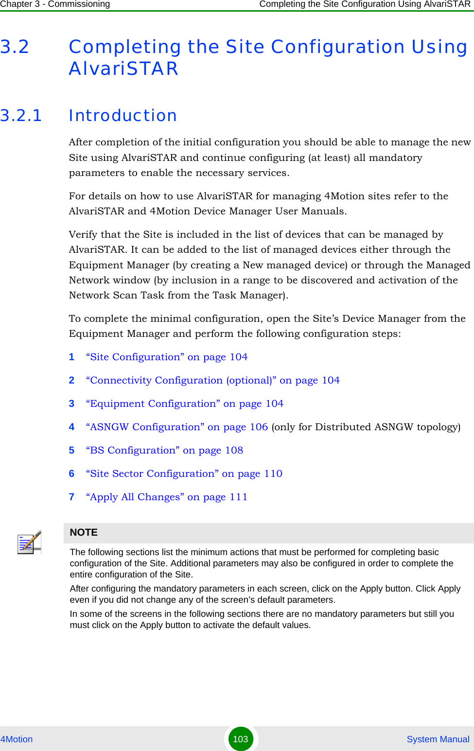
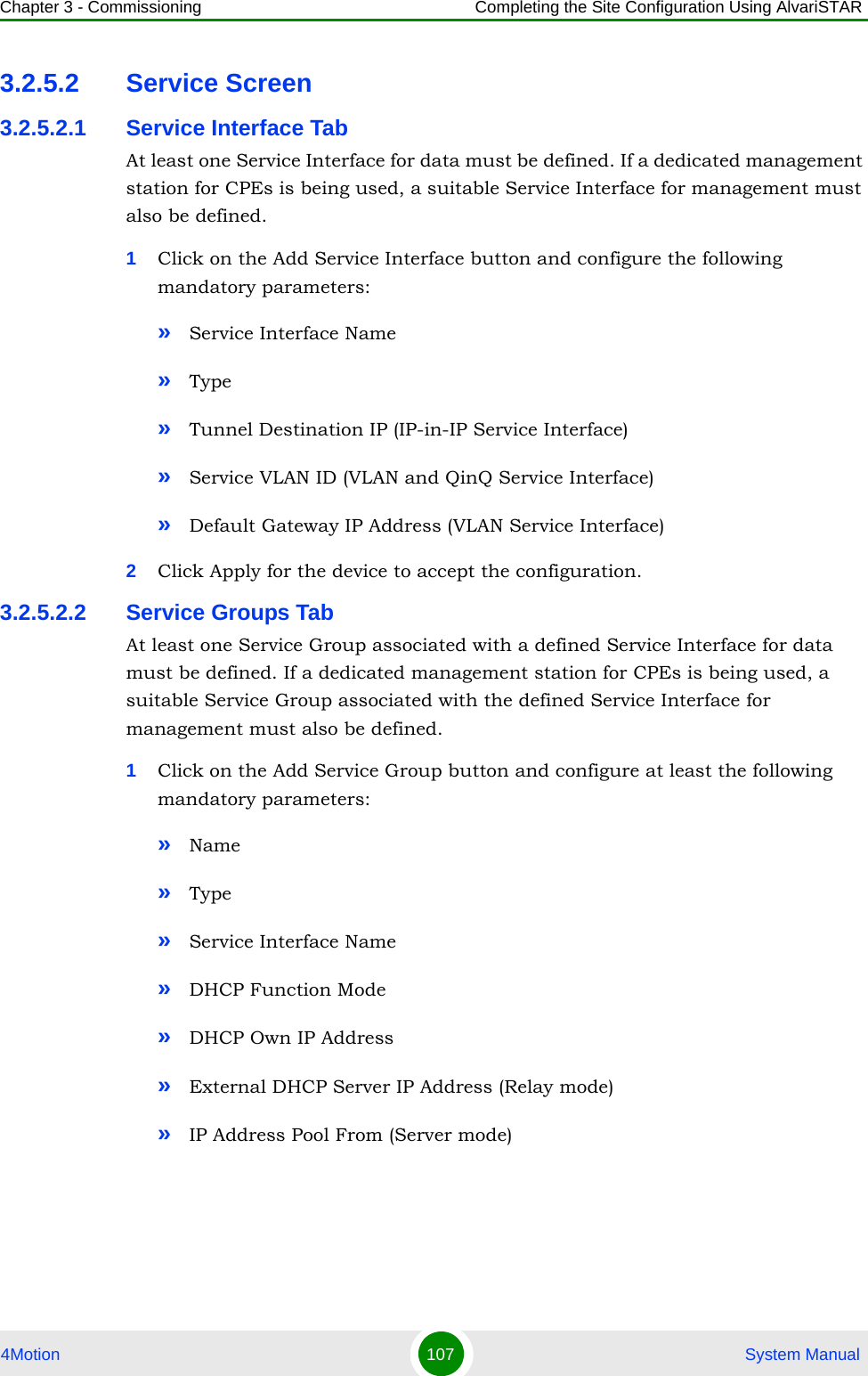
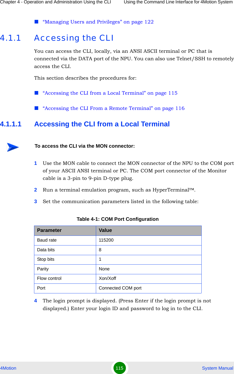
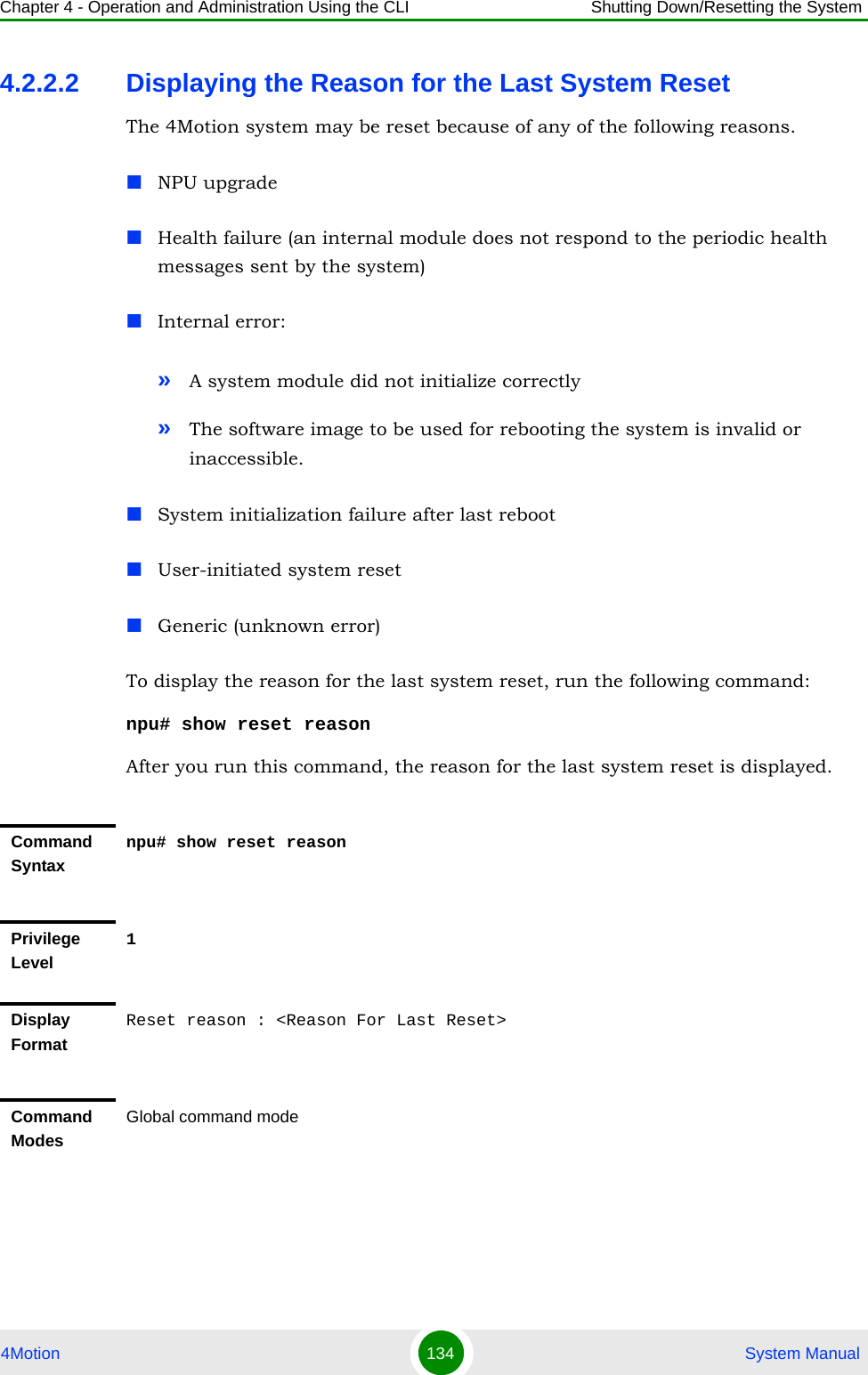
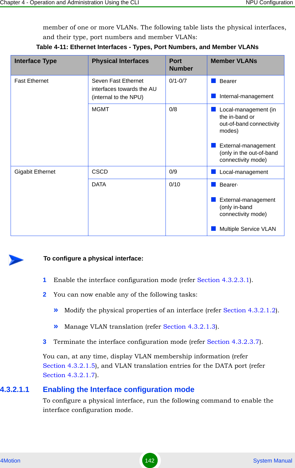
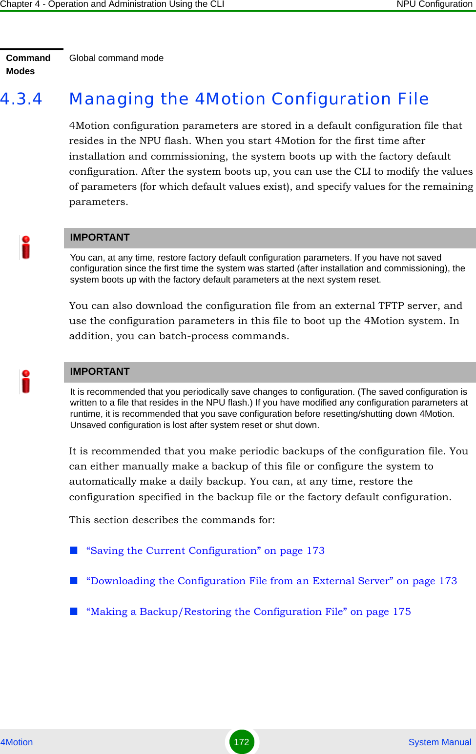
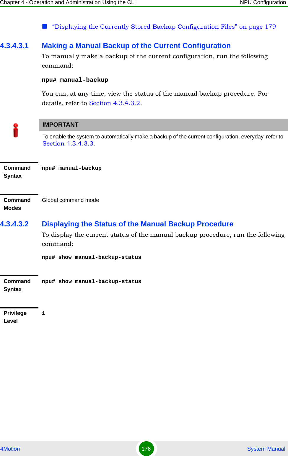
![Chapter 4 - Operation and Administration Using the CLI Using the Command Line Interface for 4Motion System 4Motion 121 System Manual4.1.4.2 Using the CLI HelpThe CLI provides help that you can access while using the CLI. Execute the following command to obtain help for a specific command:help [“<text>”]Specify the command name as the parameter to view help for this command. For example, to obtain help for the show resource limits command, run the following command:npu# help “show resource limits”The help for the show resource limits command is displayed. If you do not provide the command name as the parameter, all commands that can be executed in the current command mode are displayed.4.1.4.3 Using the History FeatureThe history feature of the CLI maintains a sequential list of all previously executed commands. The following table lists the commands that you can run to access, edit or execute a command from the command history list:Table 4-5: Control Characters for Using the CLIPress To...Up/Down arrow keys Scroll the previously executed CLI commands. Press Enter if you want to select and execute a particular command.Right/Left arrow keys Navigate to the right/left of the selected character in a command.Home key Navigate to the first character of a command.End key Navigate to the last character of a command.Backspace key Delete the characters of a command.TAB key Prompt the CLI to complete the command for which you have specified a token command. Remember that the CLI that is the nearest match to the token command that you have specified is displayed.? key View the list of commands available in the current mode. If you press ? after a command, a list of parameters available for that command is displayed.](https://usermanual.wiki/Alvarion-Technologies/BMAX-OR-25.Manual-2/User-Guide-1114030-Page-25.png)
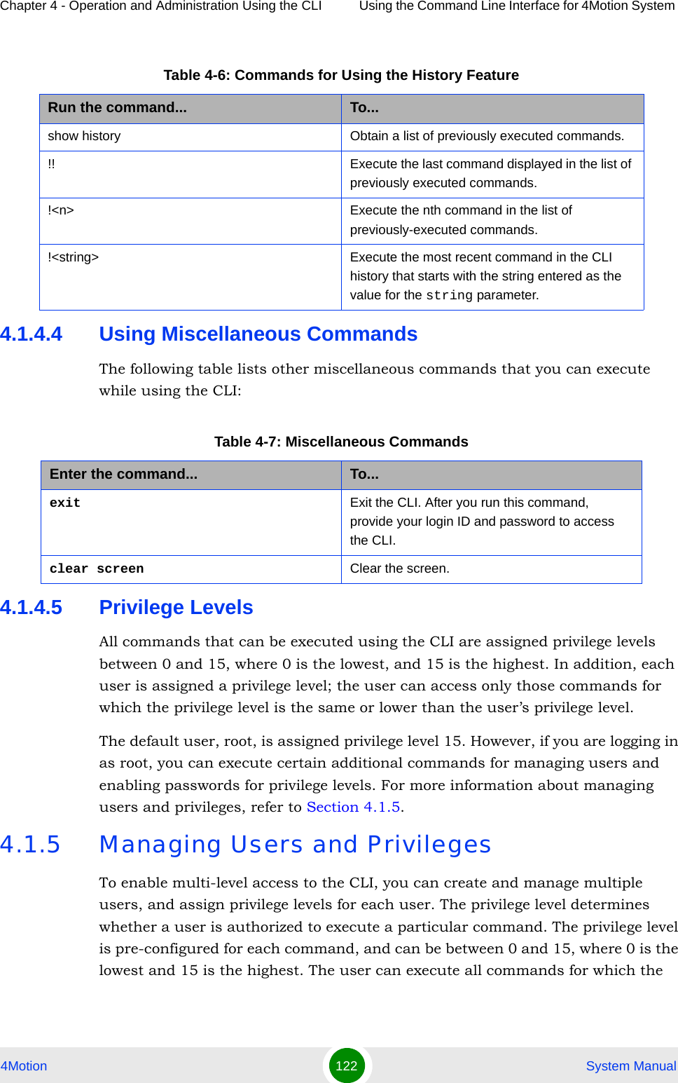
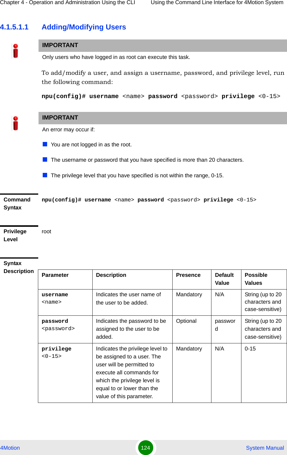
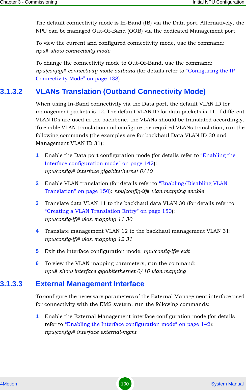
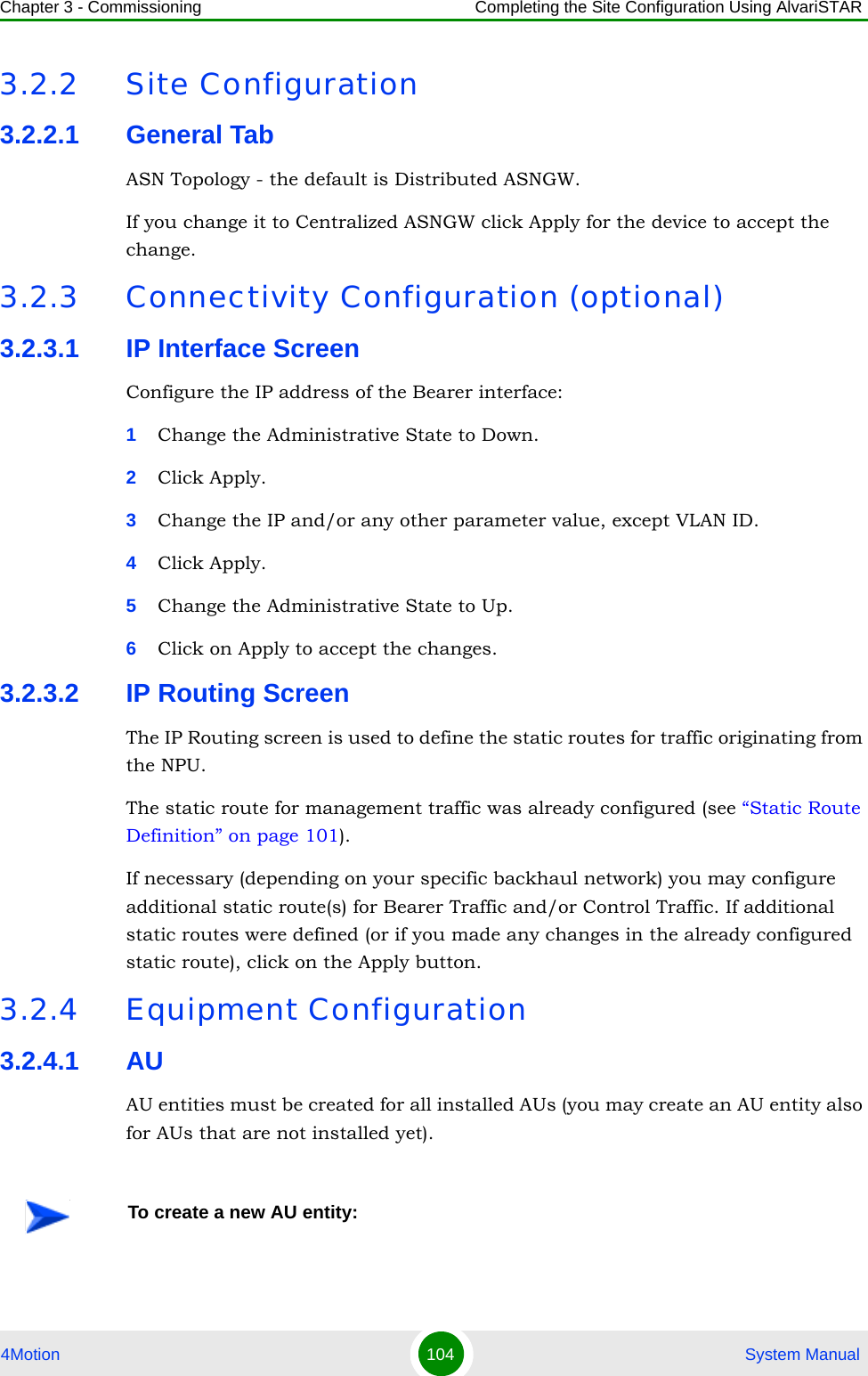
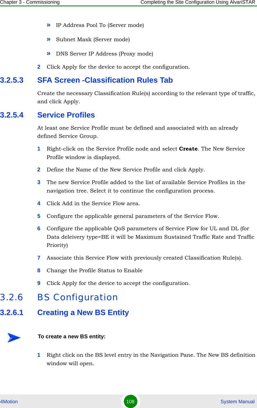
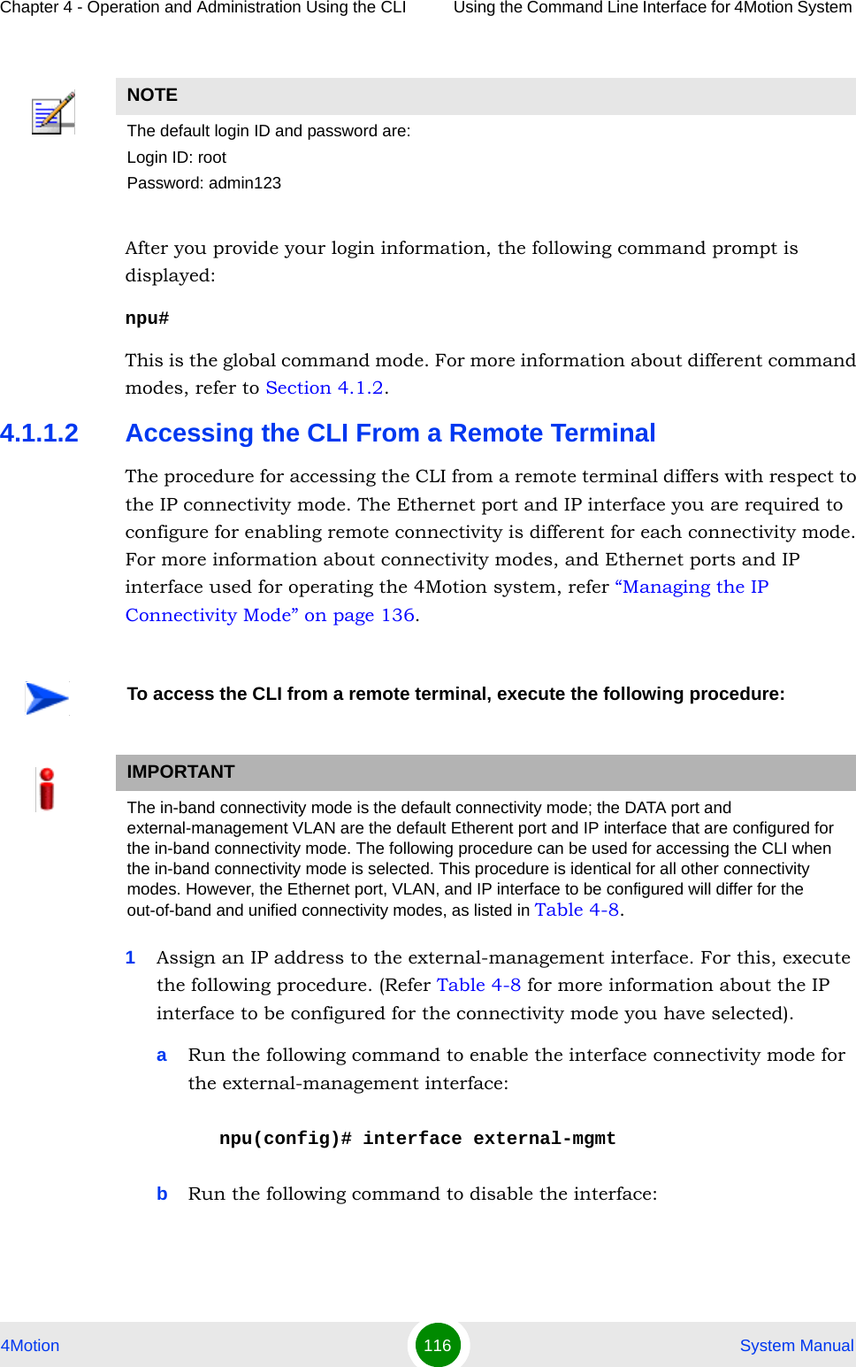
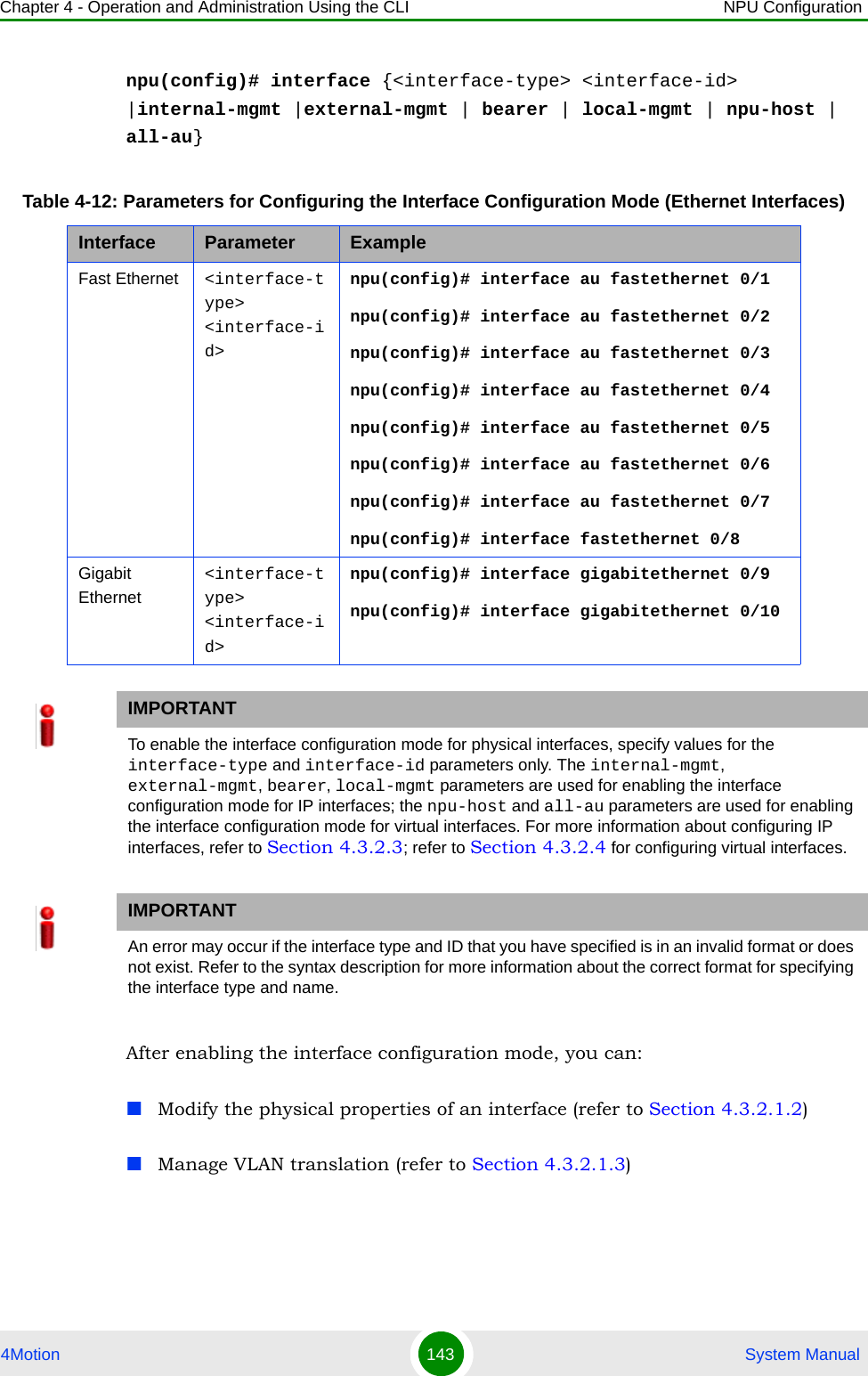
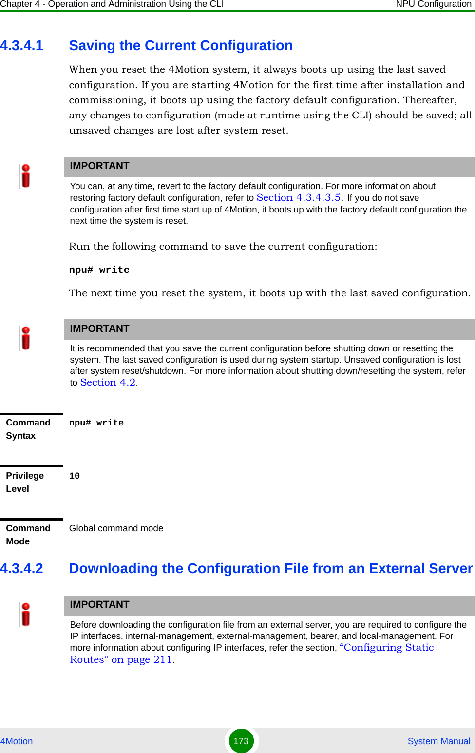
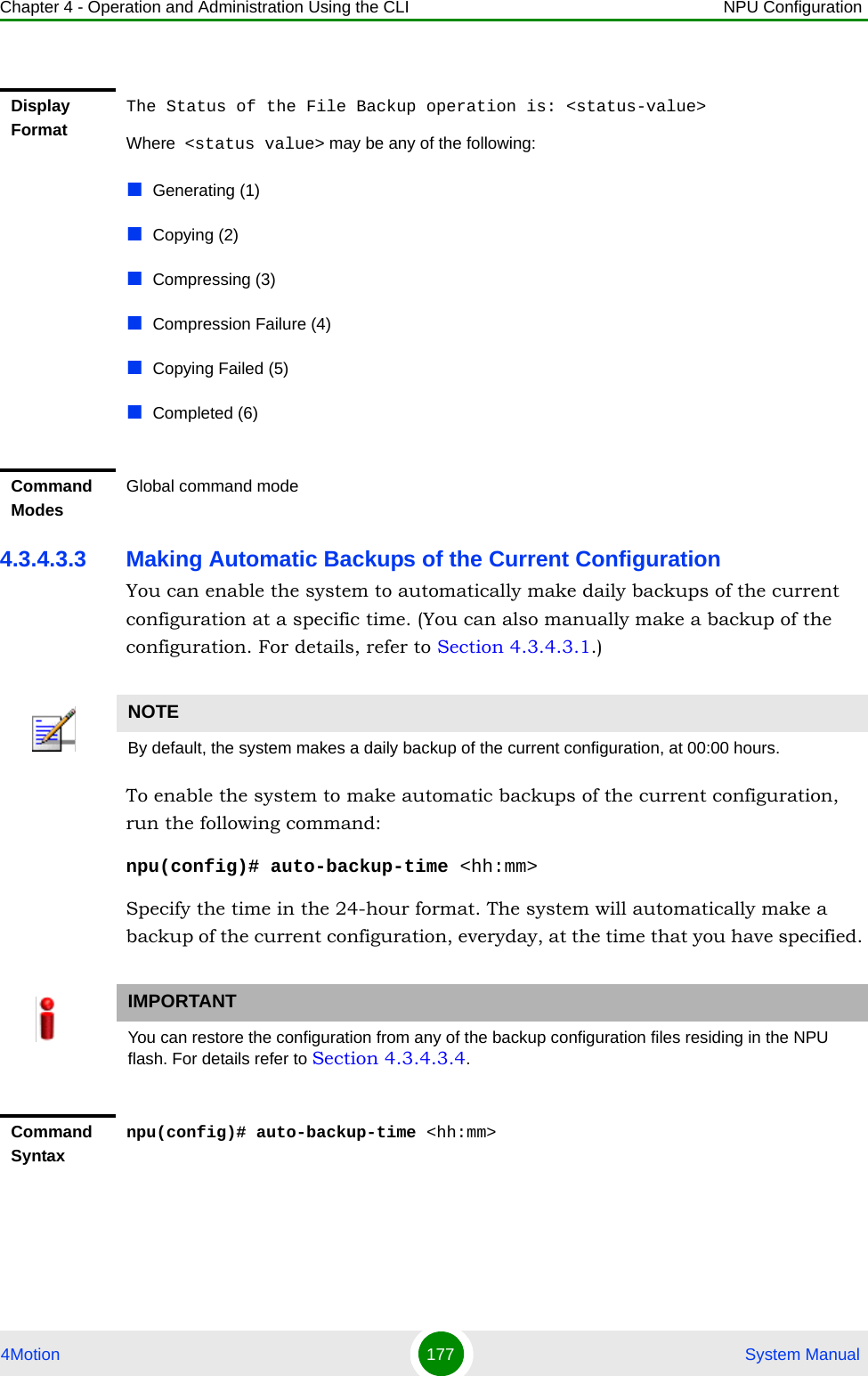
![Chapter 4 - Operation and Administration Using the CLI Using the Command Line Interface for 4Motion System 4Motion 126 System Manual4.1.5.2 Managing PrivilegesTo enable users to execute commands that require a higher privilege level (than their currently configured default level), you can configure a password for each privilege level. Other users can then use the password you have specified to enable a higher privilege level. This section describes the commands for:“Assigning a Password for a Privilege Level” on page 126“Deleting a Password for a Privilege Level” on page 1274.1.5.2.1 Assigning a Password for a Privilege LevelTo assign a password for a privilege level, run the following command:npu(config)# enable password [Level <0-15>] <password> IMPORTANTOnly users who have logged in as root can assign or delete passwords for any privilege level.IMPORTANTOnly users who have logged in as root can execute this command.IMPORTANTAfter you execute this command, any user can use this password to enable the (higher) privilege level for which you have configured the password. For more information about using passwords for enabling higher privilege levels, refer Section 4.1.5.3.IMPORTANTAn error may occur if:You are trying to configure a password for a privilege level that is higher than your default privilege level. The password that you have specified is more than 20 characters.The privilege level that you have specified is not within the range, 0-15.Command Syntaxnpu(config)# enable password [Level <0-15>] <password>](https://usermanual.wiki/Alvarion-Technologies/BMAX-OR-25.Manual-2/User-Guide-1114030-Page-30.png)
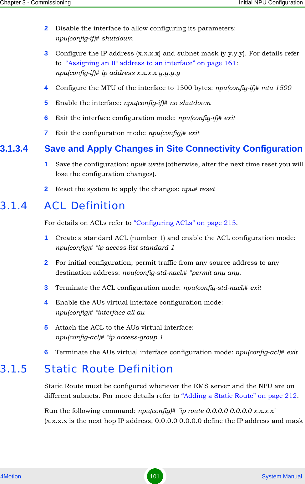
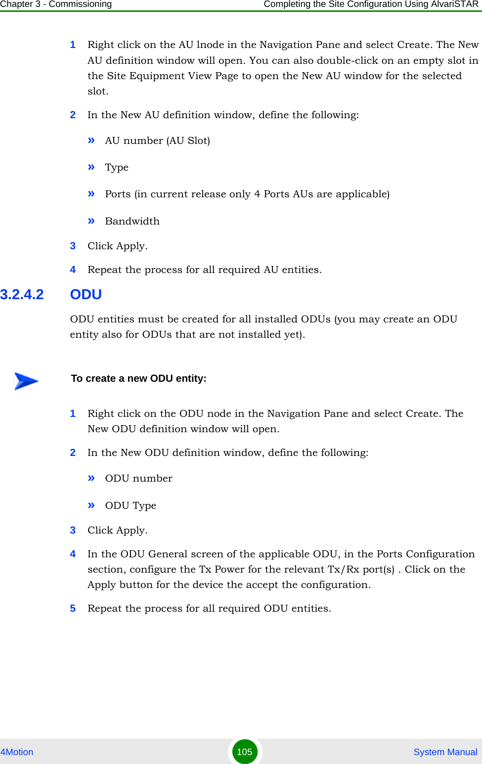
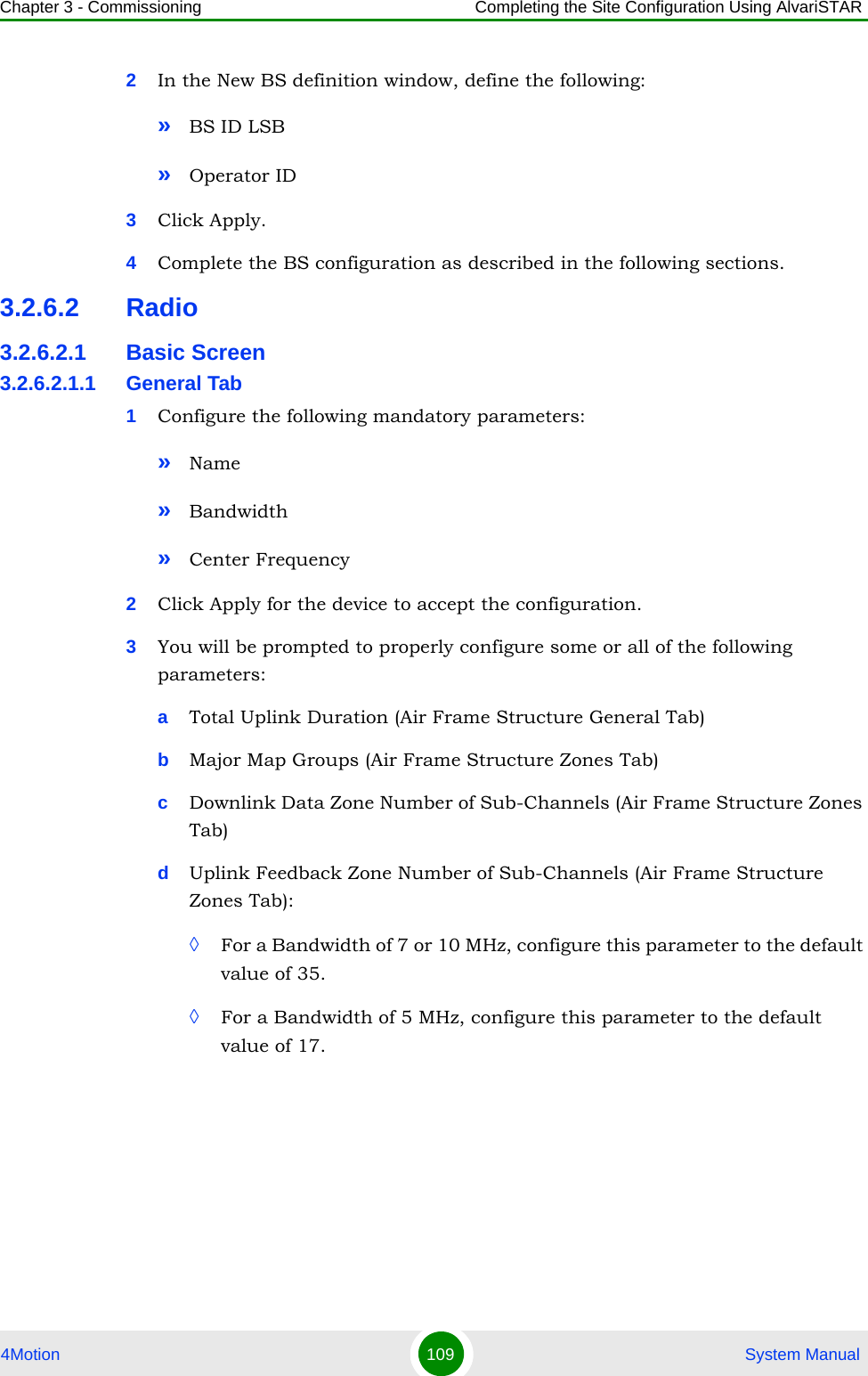
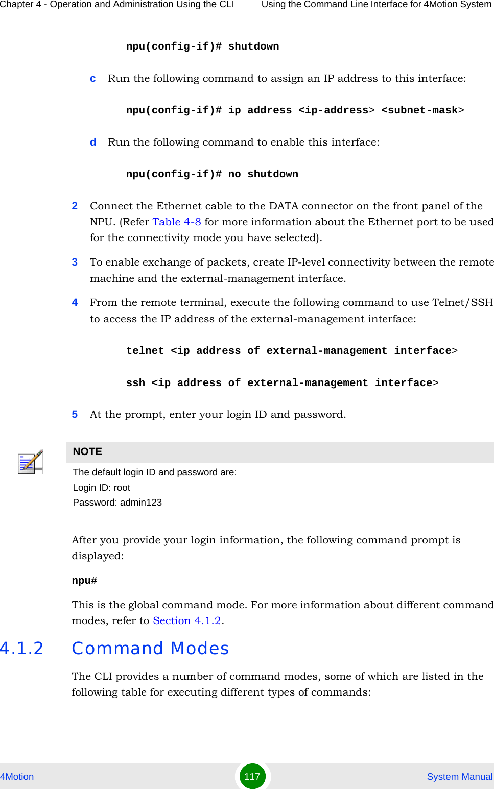
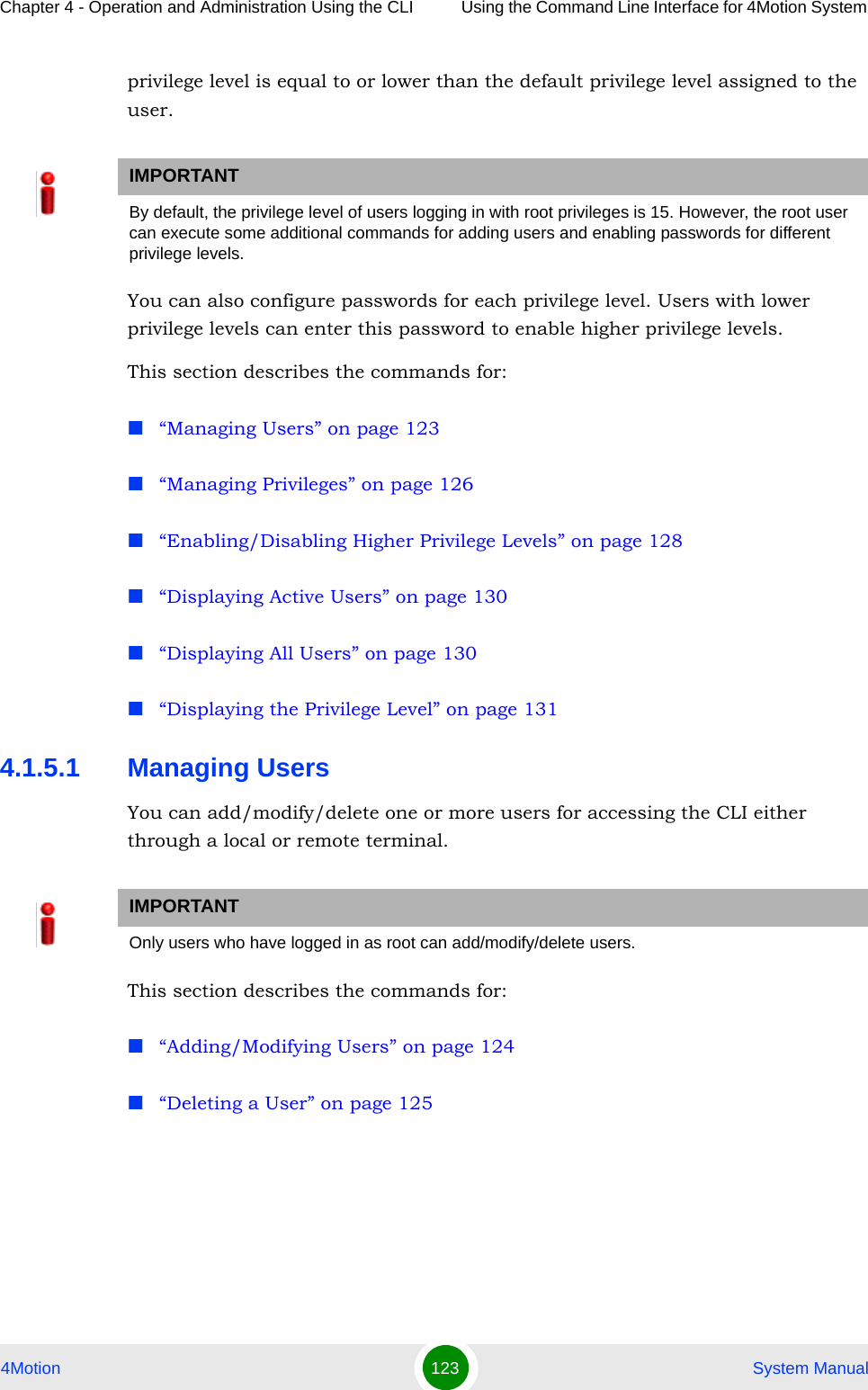
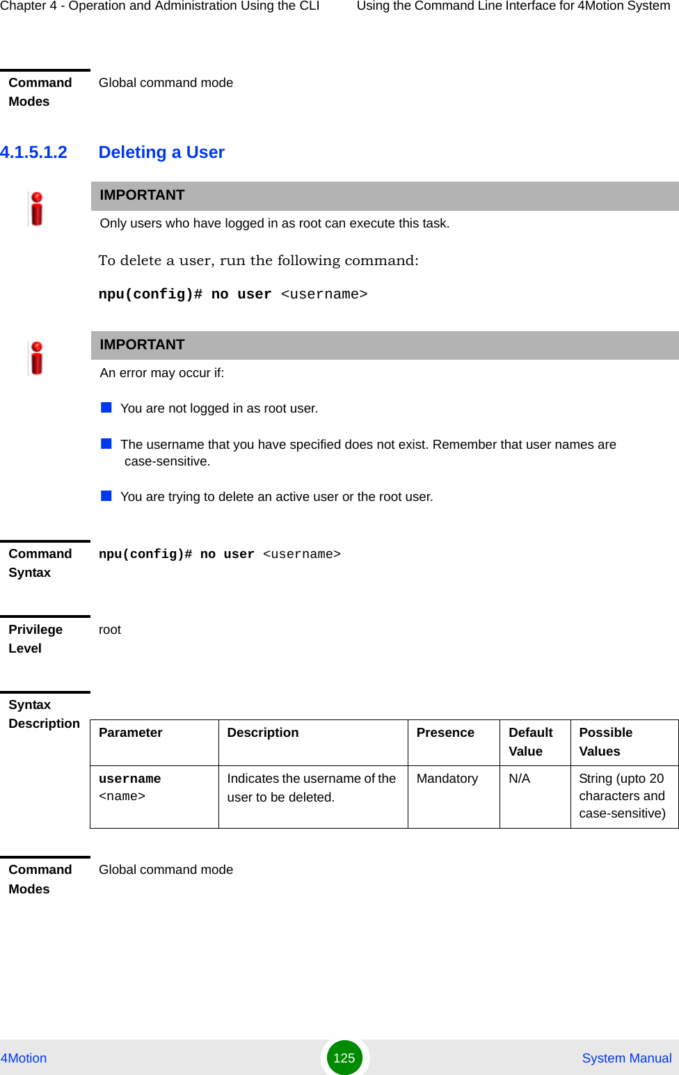
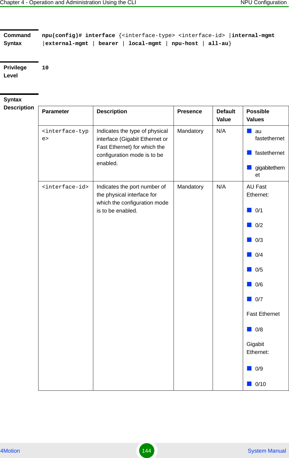
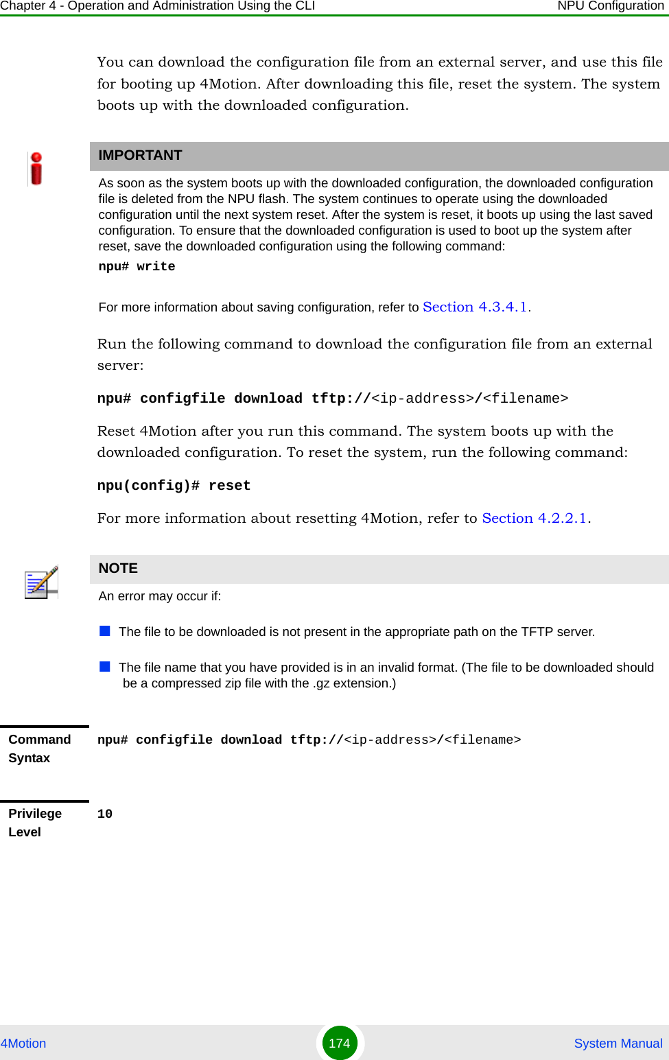
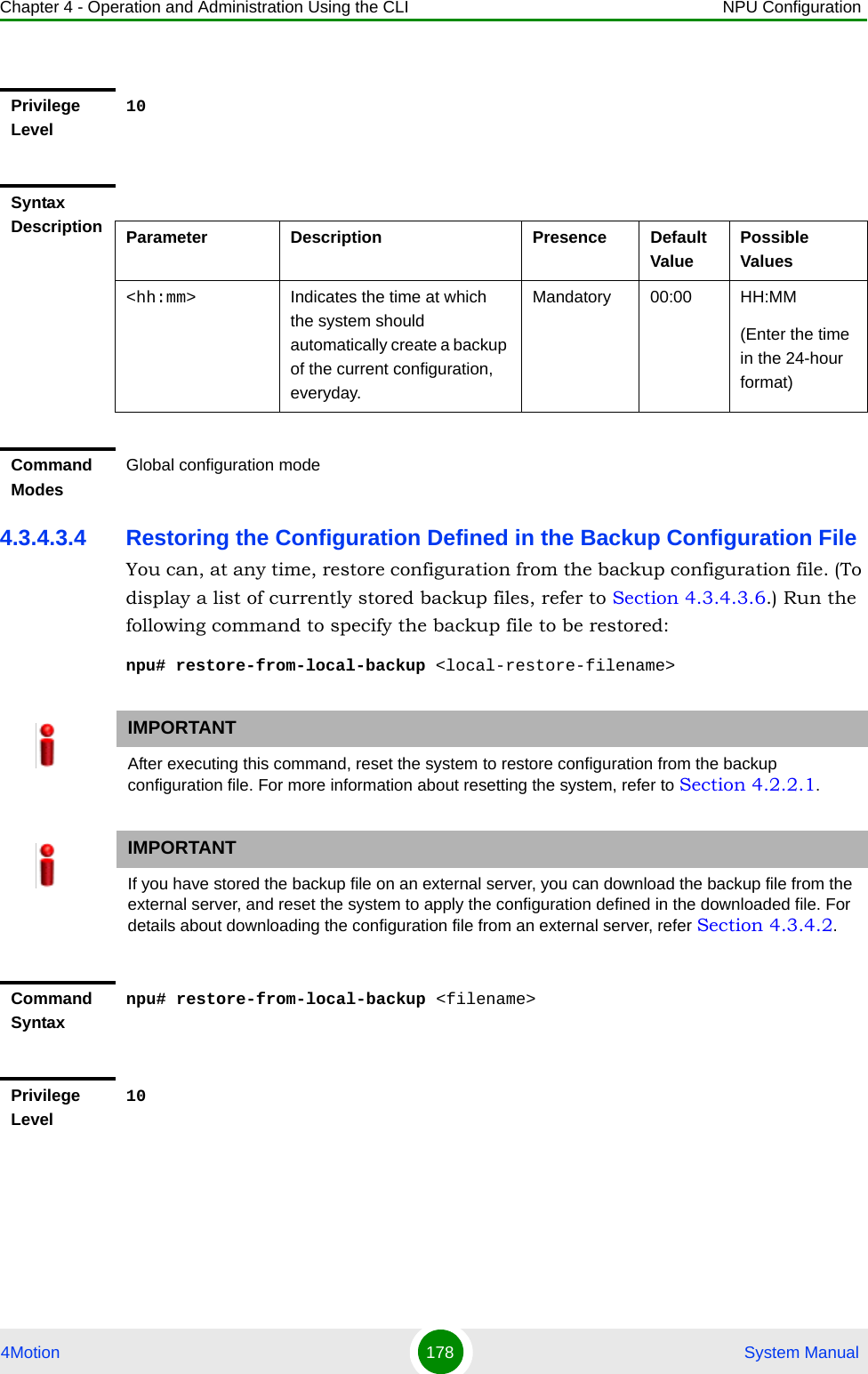
![Chapter 4 - Operation and Administration Using the CLI Using the Command Line Interface for 4Motion System 4Motion 127 System Manual4.1.5.2.2 Deleting a Password for a Privilege LevelTo delete a password for a privilege level, run the following command:npu(config)# no enable password [Level <0-15>]Privilege Level15Syntax Description Parameter Description Presence Default ValuePossible Values[Level <0-15>] Indicates the privilege level for which a password is to be enabled.Optional 15 0-15<password> Denotes the password to be assigned for the current privilege level.Mandatory N/A String (up to 20 characters and case-sensitive)Command ModesGlobal configuration modeIMPORTANTOnly users who have logged in as root can execute this command.IMPORTANTAn error may occur if:The privilege level that you have specified is not within the range, 0-15.You are trying to delete a password for a privilege level that is higher than your default privilege level.Command Syntaxnpu(config)# no enable password [Level <0-15>]Privilege Levelroot](https://usermanual.wiki/Alvarion-Technologies/BMAX-OR-25.Manual-2/User-Guide-1114030-Page-31.png)
![Chapter 4 - Operation and Administration Using the CLI Using the Command Line Interface for 4Motion System 4Motion 128 System Manual4.1.5.3 Enabling/Disabling Higher Privilege LevelsYou can execute commands that require higher privilege levels. If the root user has configured a password for that level, you can use that password to enable higher privilege levels.For example, if your privilege level is 1, you can provide the password configured for privilege level 10 to execute all commands that require privilege level 10.This section describes the commands for:“Enabling a Higher Privilege Level” on page 128“Returning to the Default Privilege Level” on page 1294.1.5.3.1 Enabling a Higher Privilege Level1Log in to the CLI.2Run the following command to specify the privilege level and password:npu(config)# enable [Level <0-15>]3At the password prompt, specify the password configured for the privilege level that you have specified.If you specify the correct password, you are logged in to the CLI with the privilege level that you had specified. You can now execute all commands that require the current privilege level.Syntax Description Parameter Description Presence Default ValuePossible Values[Level <0-15>] Indicates the privilege level for which a password is to be disabled.Optional 10 015Command SyntaxGlobal configuration modeTo enable a higher privilege level:](https://usermanual.wiki/Alvarion-Technologies/BMAX-OR-25.Manual-2/User-Guide-1114030-Page-32.png)
![Chapter 4 - Operation and Administration Using the CLI Using the Command Line Interface for 4Motion System 4Motion 129 System ManualYou can, at any time, return to your default privilege level. For details, refer Section 4.1.5.3.2.4.1.5.3.2 Returning to the Default Privilege LevelRun the following command to disable the current privilege level, and return to your default privilege level:npu(config)# disable [Level <0-15>]After you run this command, you automatically return to your default privilege level. You can display your current privilege level, using the following command:npu# show privilege NOTEYou can display your current privilege level, using the following command:npu# show privilege NOTEAn error may occur if:You have specified an incorrect password. Remember that all passwords are case-sensitive.No password is not configured for the privilege level you are trying to access.Command Syntaxnpu(config)# enable [Level <0-15>]Privilege Level0Syntax Description Parameter Description Presence Default ValuePossible Values[Level <0-15>] Indicates the privilege level you want to enable.Mandatory N/A 0-15Command ModesGlobal configuration mode](https://usermanual.wiki/Alvarion-Technologies/BMAX-OR-25.Manual-2/User-Guide-1114030-Page-33.png)
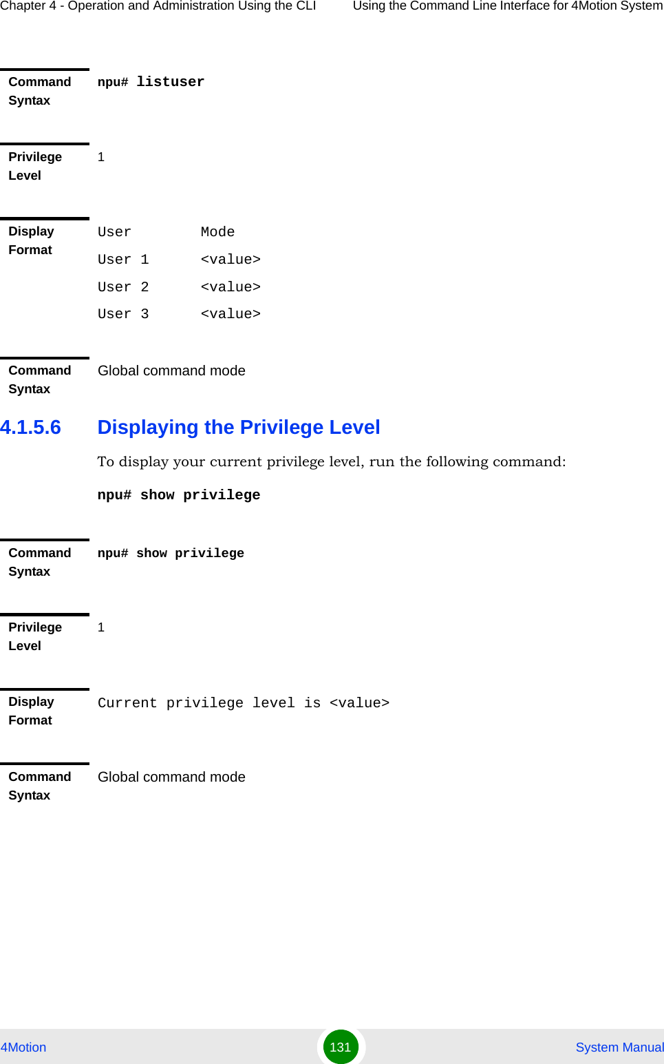
![Chapter 4 - Operation and Administration Using the CLI Using the Command Line Interface for 4Motion System 4Motion 130 System Manual4.1.5.4 Displaying Active UsersTo display all active users, run the following command:npu# show users4.1.5.5 Displaying All UsersTo display all users, run the following command:npu# listuserCommand Syntaxnpu(config)# disable [Level <0-15>]Privilege Level0Syntax Description Parameter Description Presence Default ValuePossible Values[Level <0-15>] Indicates the privilege level you want to disable.Mandatory N/A 0-15Command ModesGlobal configuration modeCommand Syntaxnpu# show usersPrivilege Level1Display FormatLine User Peer Address0 con <user name> <value>Command SyntaxGlobal command mode](https://usermanual.wiki/Alvarion-Technologies/BMAX-OR-25.Manual-2/User-Guide-1114030-Page-34.png)
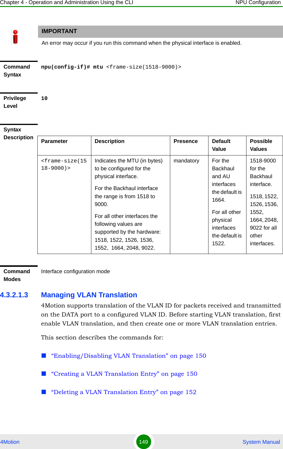
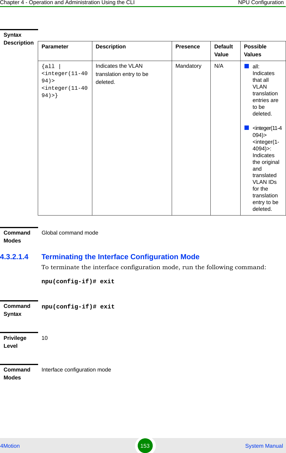
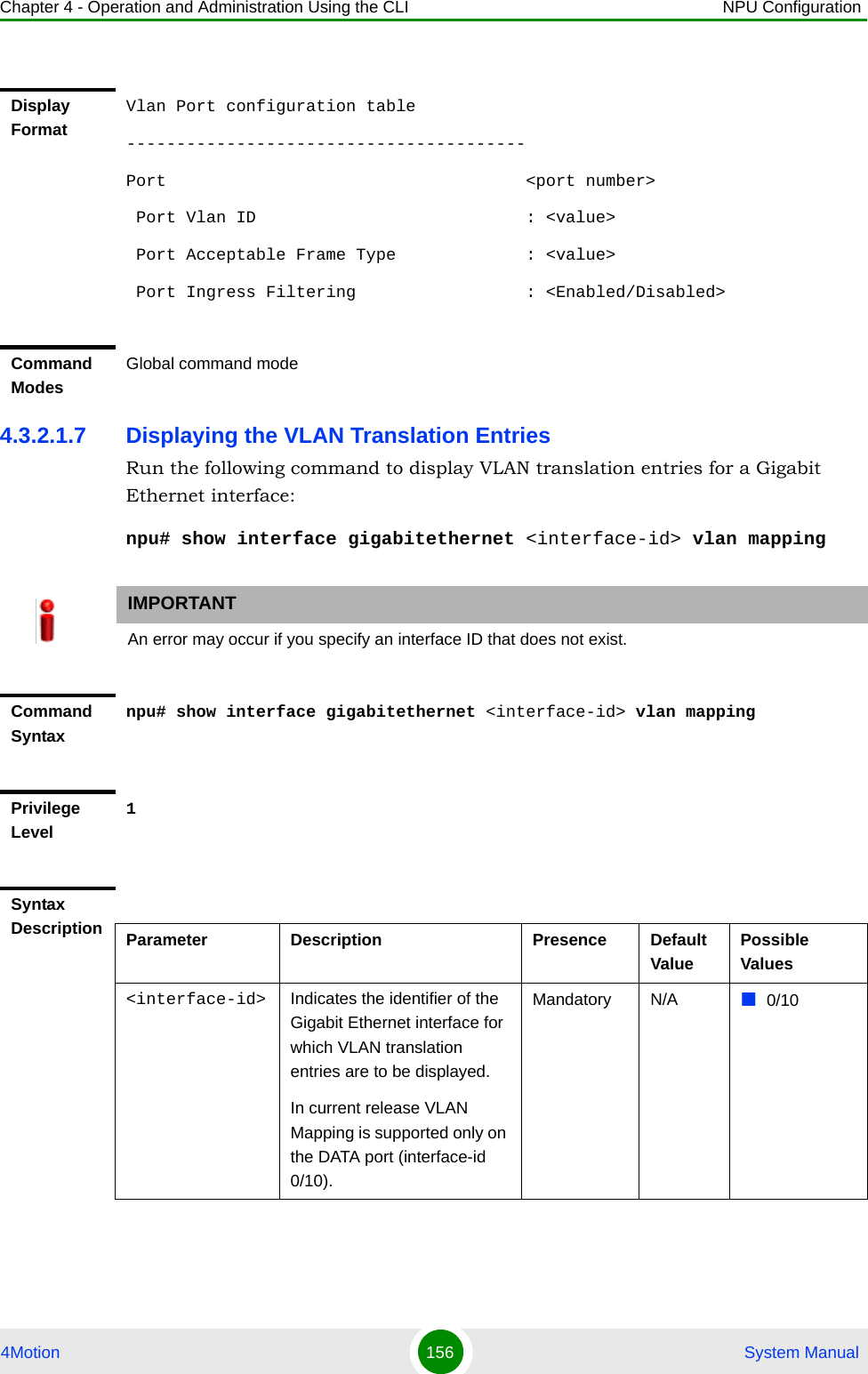
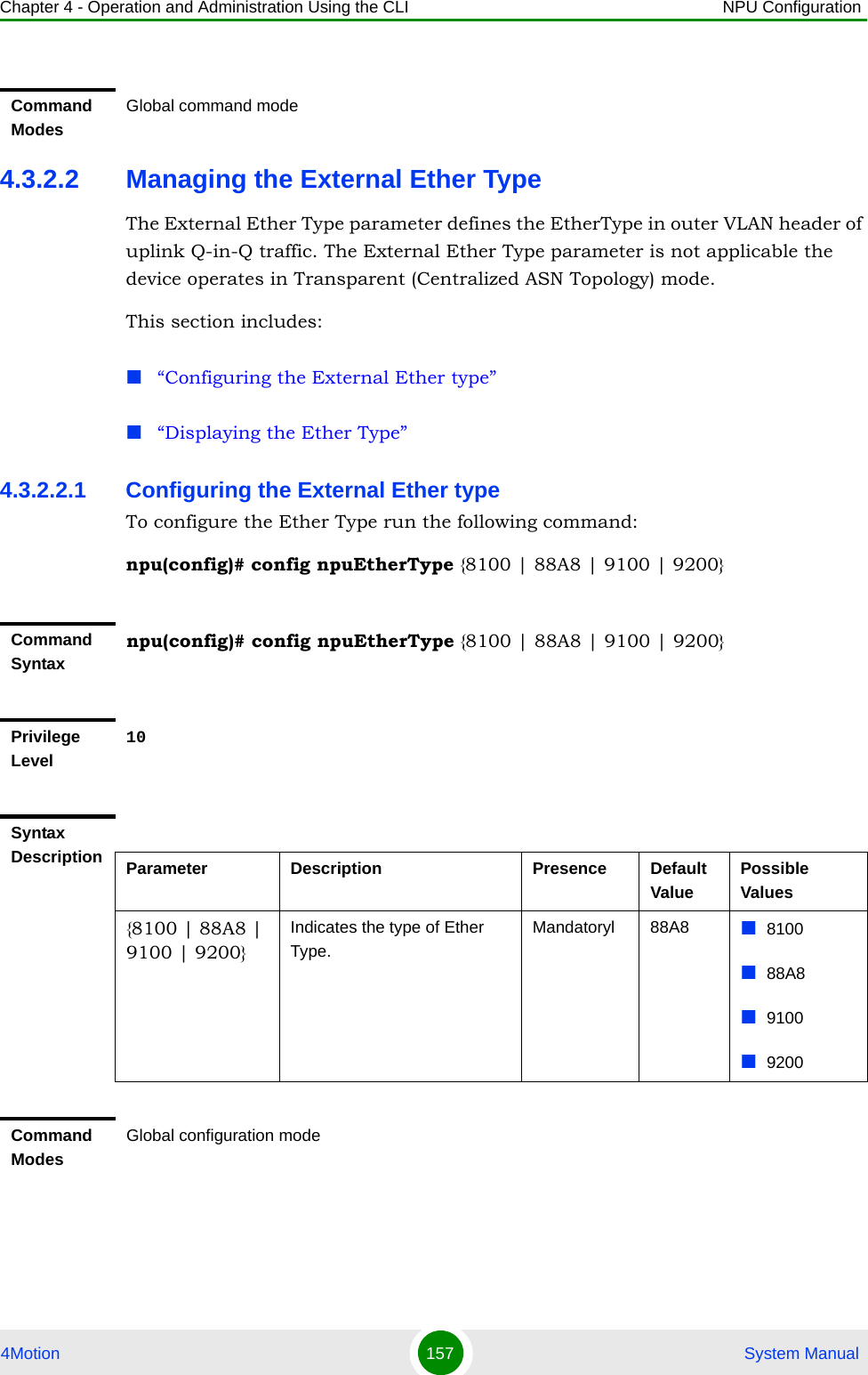
![Chapter 4 - Operation and Administration Using the CLI NPU Configuration4Motion 154 System Manual4.3.2.1.5 Displaying VLAN Membership InformationRun the following command to display Ethernet interfaces that are members of a particular or all VLAN:npu# show vlan [id <vlan-id(11-4094)>]Do not specify the VLAN ID if you want to view membership information for all VLANs.4.3.2.1.6 Displaying VLAN Configuration Information for Physical InterfacesTo display the configuration information for a VLAN that is bound to a particular physical interface, run the following command:npu# show vlan port config [port <interface-type> <interface-id>]Command Syntaxnpu# show vlan [id <vlan-id(11-4094)>]Privilege Level1Syntax Description Parameter Description Presence Default ValuePossible Values[id <vlan-id(11-4094)>]Indicates the VLAN ID for which membership information is to be displayed. Do not specify any value for this parameter if you want to view VLAN membership information for all VLANs.Mandatory N/A 11-4096Display FormatVlan Name Ports ---- ---- ----- <VLAN ID <>VLAN Name> <member ports><VLAN ID <>VLAN Name> <member ports>Command ModesGlobal command mode](https://usermanual.wiki/Alvarion-Technologies/BMAX-OR-25.Manual-2/User-Guide-1114030-Page-58.png)
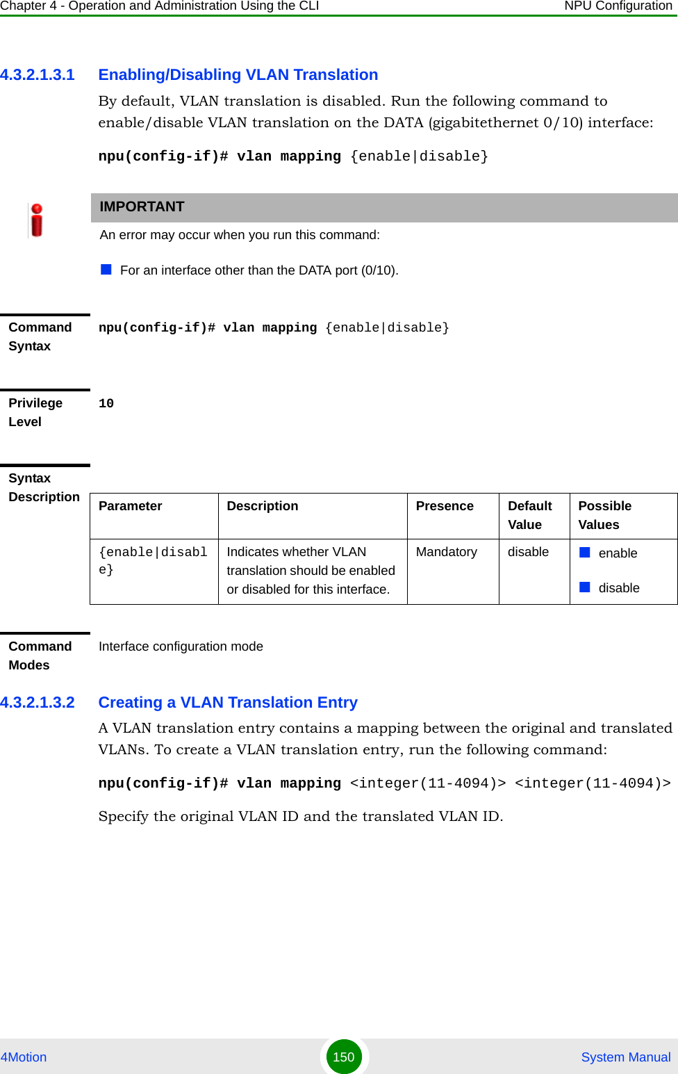
![Chapter 4 - Operation and Administration Using the CLI NPU Configuration4Motion 155 System ManualDo not specify the port number and type if you want to display configuration information for all physical interfaces. IMPORTANTAn error may occur if you specify an interface type or ID that does not exist.Command Syntaxnpu# show vlan port config [port <interface-type> <interface-id>]Privilege Level1Syntax Description Parameter Description Presence Default ValuePossible Values<interface-type>Indicates the type of physical interface for which VLAN membership information is to be displayed.Optional N/A fastethernetgigabitethernet<interface-id> Indicates the ID of the physical interface for which VLAN membership information is to be displayed.Optional N/A Fast Ethernet:0/10/20/30/40/50/60/70/8Gigabit Ethernet:0/90/10](https://usermanual.wiki/Alvarion-Technologies/BMAX-OR-25.Manual-2/User-Guide-1114030-Page-59.png)
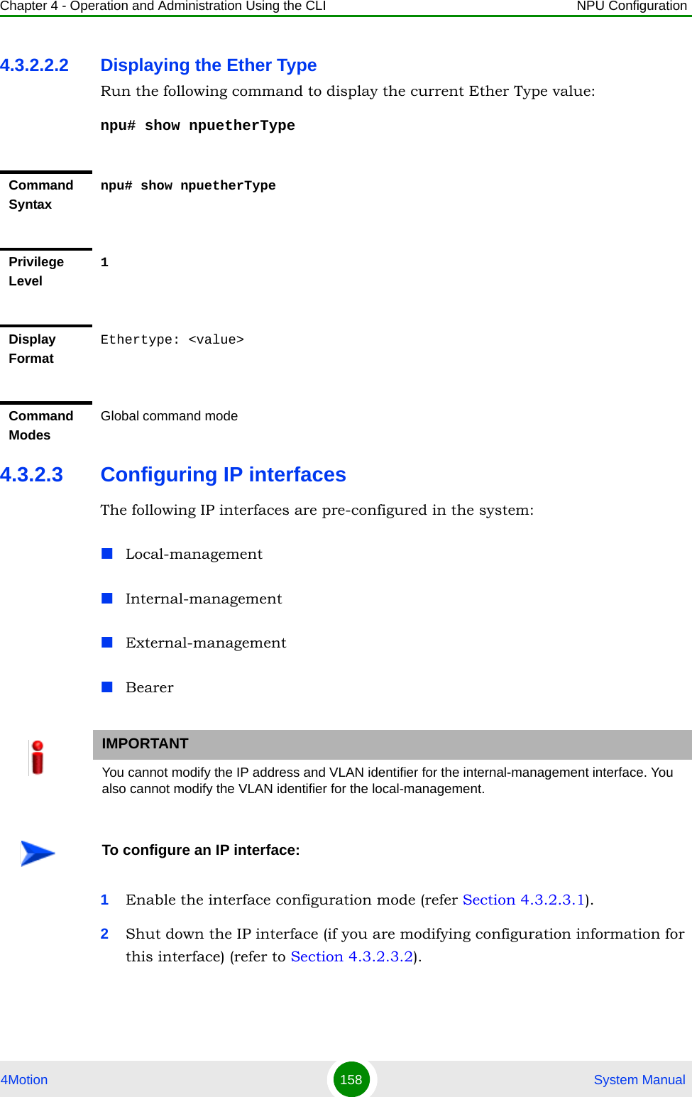
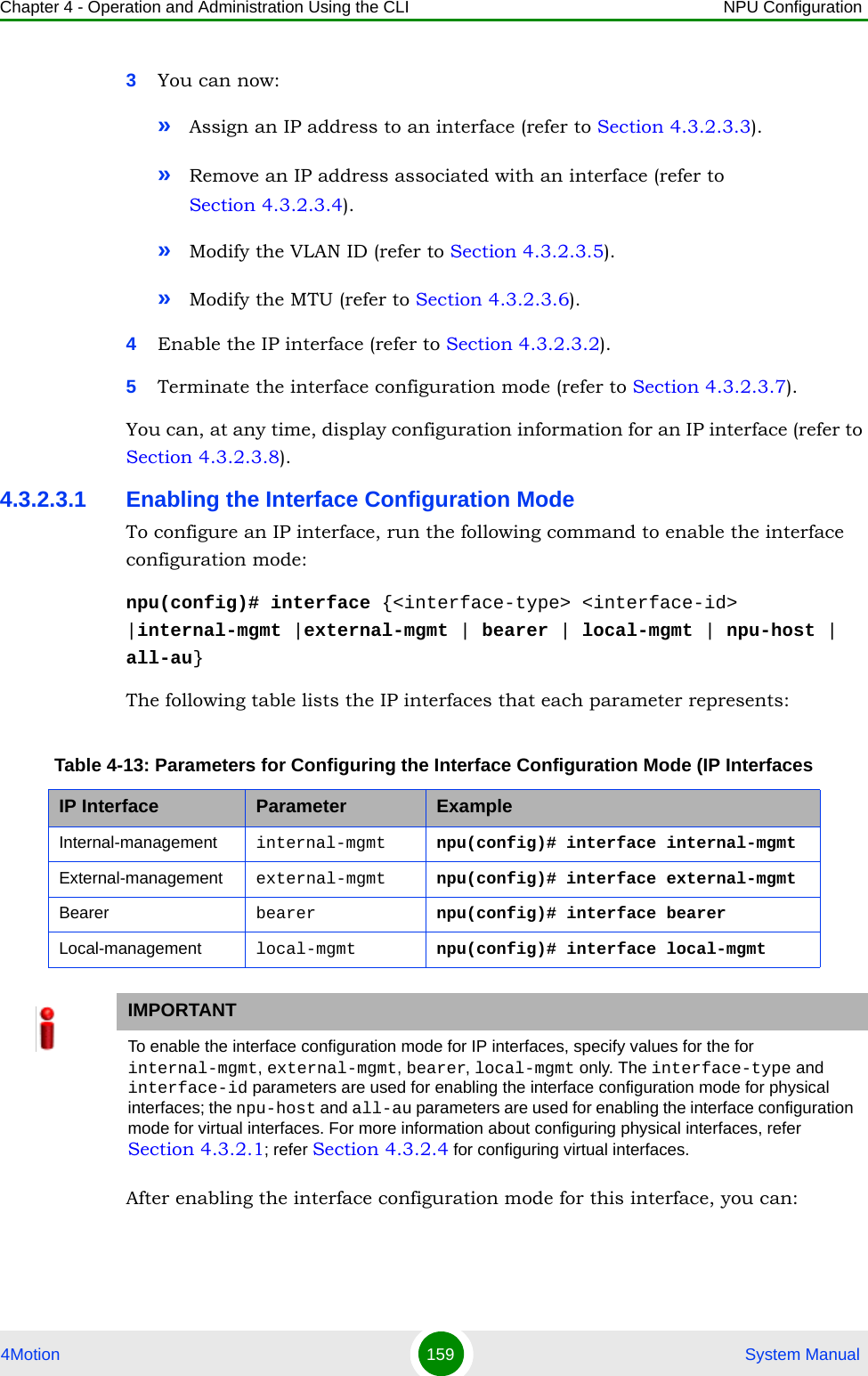
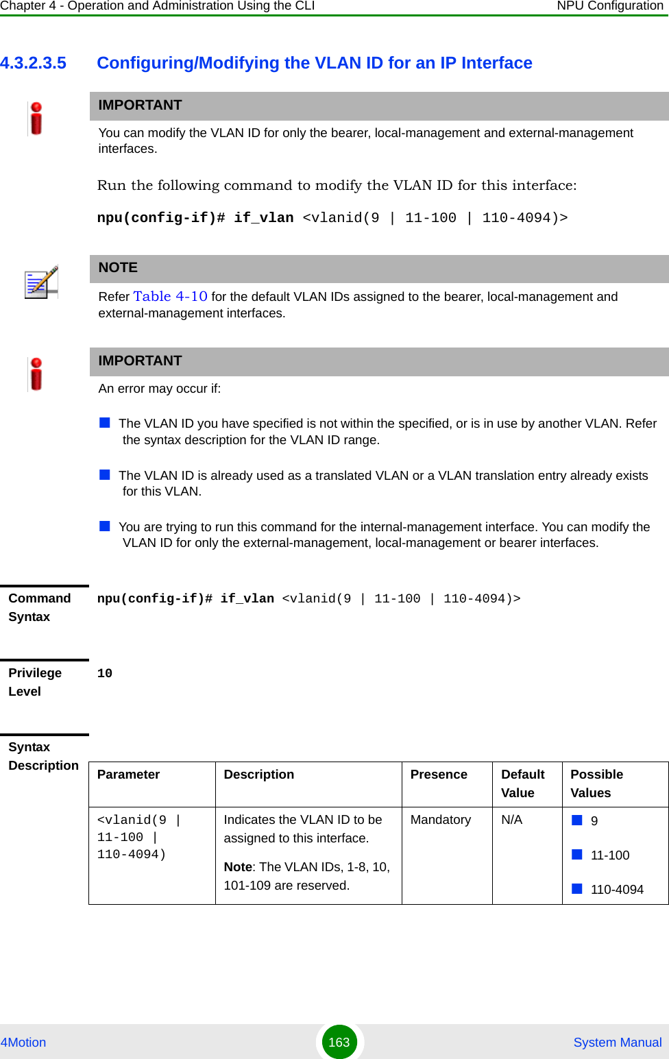
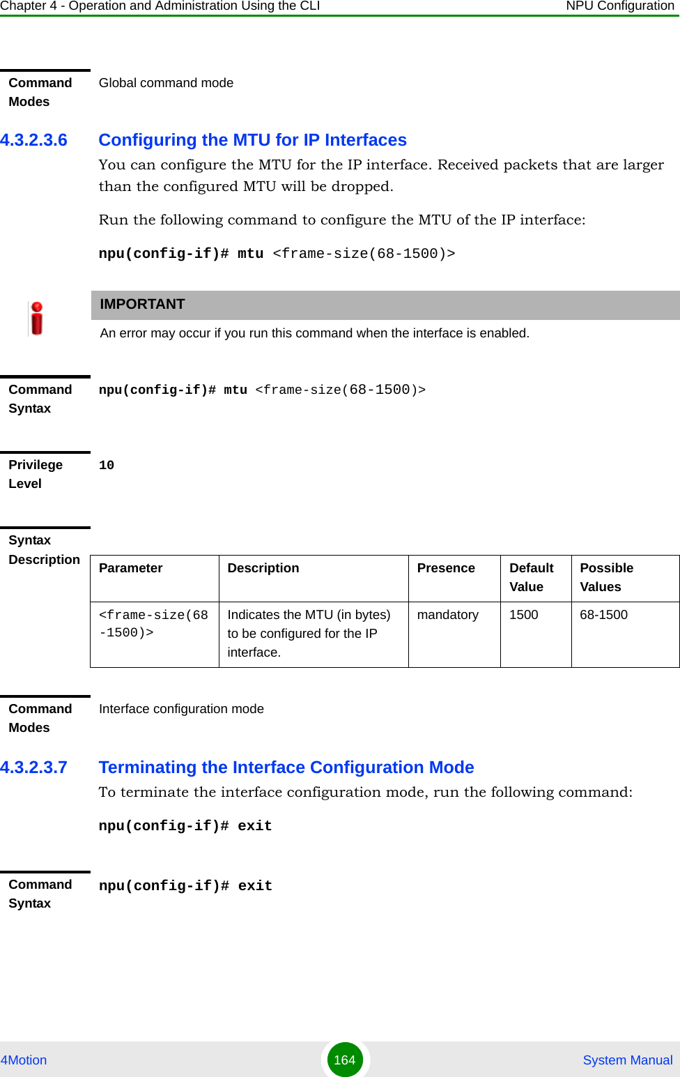
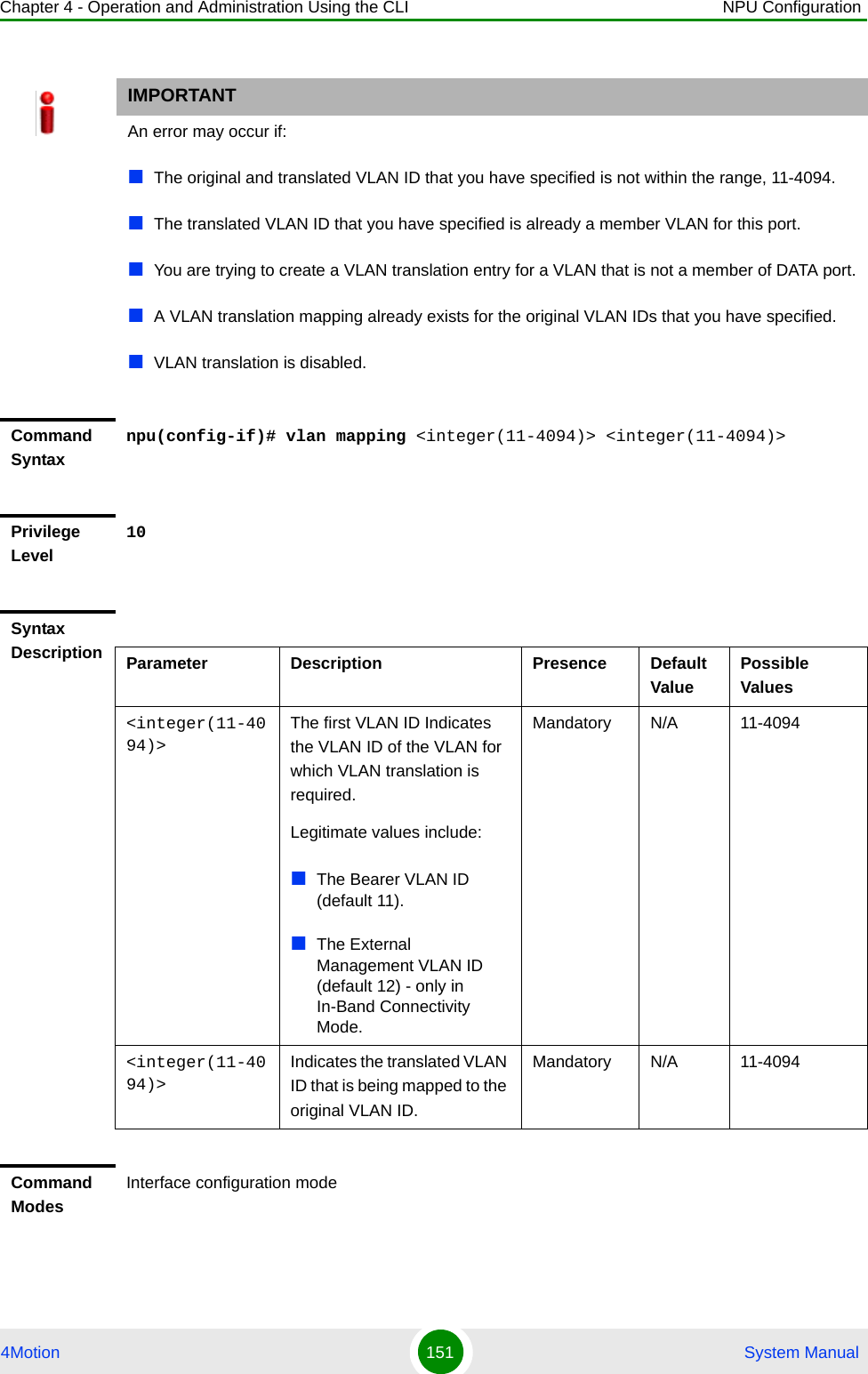
![Chapter 4 - Operation and Administration Using the CLI NPU Configuration4Motion 165 System Manual4.3.2.3.8 Displaying IP Interface Status and Configuration InformationTo display the status and configuration information for an IP interface, run the following command:npu# show ip interface [{internal-mgmt | external-mgmt | bearer | local-mgmt}]Do not specify the interface if you want to view configuration information for all IP interfaces.Privilege Level10Command ModesInterface configuration modeIMPORTANTAn error may occur if the IP interface does not exist for the configured connectivity and boot mode.Command Syntaxnpu# show ip interface [{internal-mgmt | external-mgmt | bearer | local-mgmt}]Privilege Level1Syntax Description Parameter Description Presence Default ValuePossible Values{internal-mgmt | external-mgmt | bearer | local-mgmt}Indicates the interface for which configuration information is to be displayed.Do not specify any value for this parameter if you want to view configuration information for all IP interfaces.Optional N/A internal-mgmtexternal-mgmtbearerlocal-mgmt](https://usermanual.wiki/Alvarion-Technologies/BMAX-OR-25.Manual-2/User-Guide-1114030-Page-69.png)
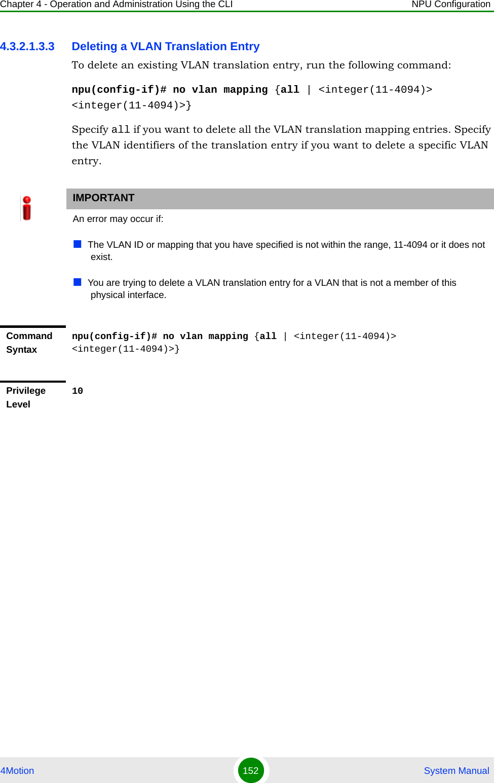
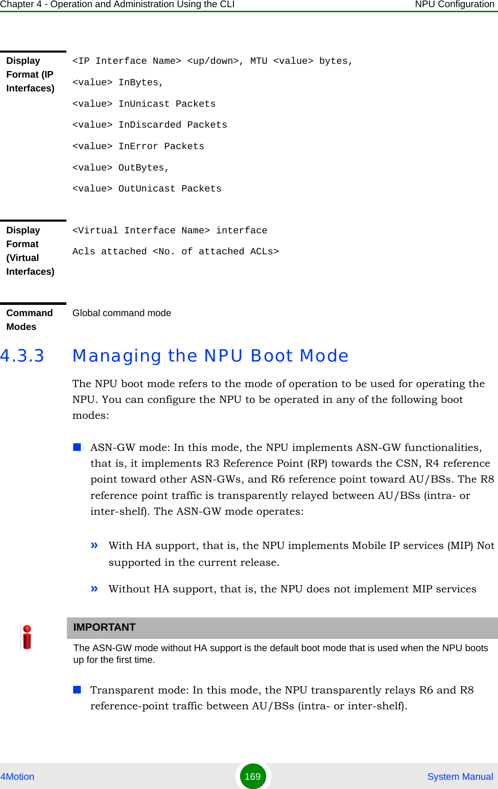
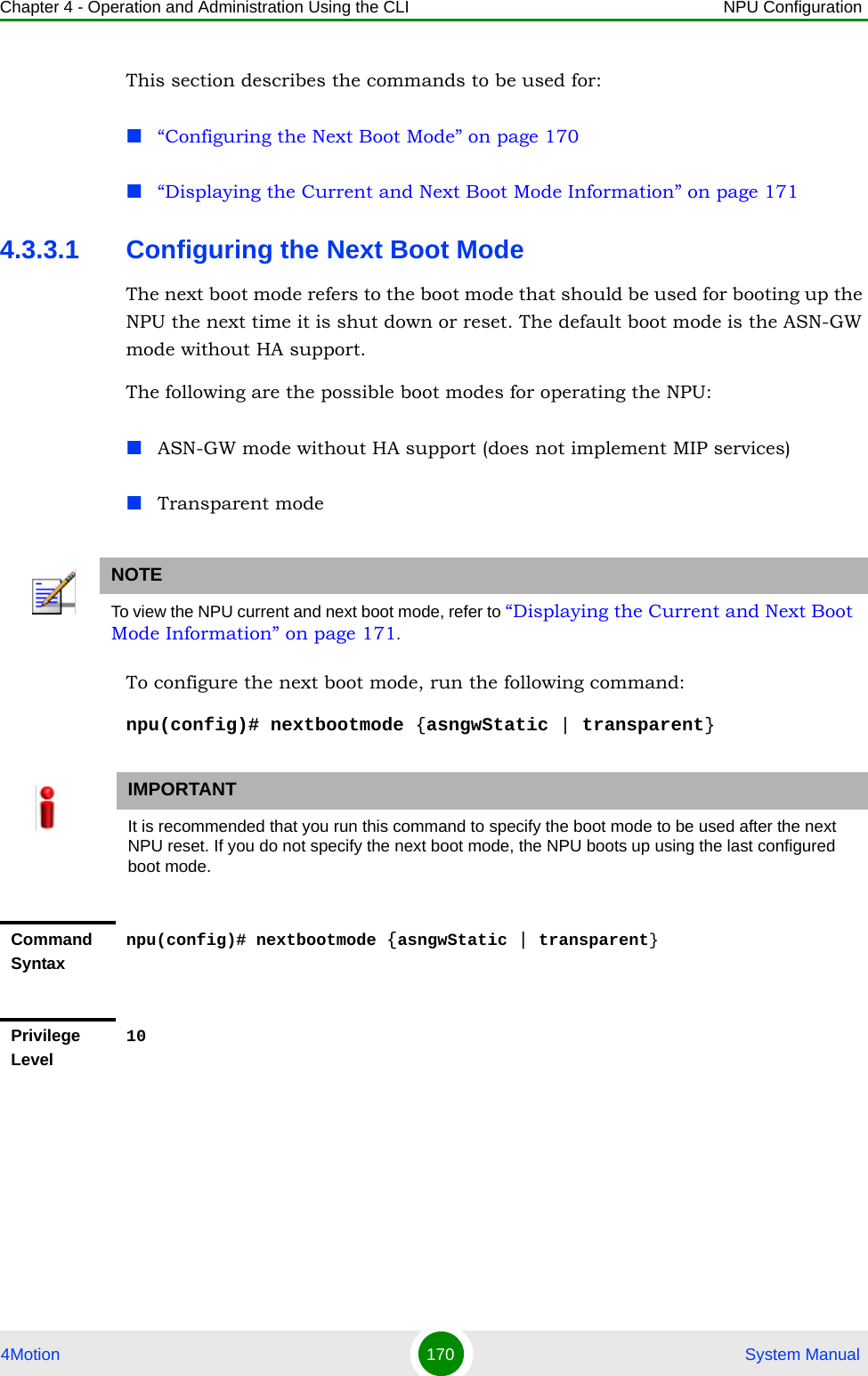
![Chapter 4 - Operation and Administration Using the CLI NPU Configuration4Motion 166 System Manual4.3.2.4 Configuring Virtual InterfacesIn addition to physical and IP interfaces, 4Motion defines the following virtual interfaces. All ACLs configured for filtering traffic destined towards the NPU or AUs, are attached to either of these interfaces.NPU-host: Used for configuring ACLs to filter traffic destined towards the NPU.All-AU: Used for configuring ACLs to filter traffic destined towards the AUs in the 4Motion shelf. For more information about attaching ACLs to the NPU or all-AUs, refer the section, “Attaching/De-attaching ACLs to/from an Interface” on page 241.4.3.2.5 Displaying Status and Configuration Information for Physical, IP, and Virtual InterfacesTo display the status and configuration information for physical, IP and/or virtual interfaces, run the following command:npu# show interfaces [{[<interface-type> <interface-id>] | internal-mgmt | external-mgmt | bearer | local-mgmt | npu-host | all-au}]To display the configuration information for all interfaces, do not specify a value for any parameter.The following table lists parameters to be specified with respect to the type of interface for which configuration information is to be displayed:Display Format<Interface Name> is <up/down> Internet Address is <value>Broadcast Address <value>Command ModesGlobal command modeTable 4-14: Parameters for Displaying Configuration Information for Physical, IP, and Virtual InterfacesInterface Parameters ExampleAll Interfaces None npu# show interfaces](https://usermanual.wiki/Alvarion-Technologies/BMAX-OR-25.Manual-2/User-Guide-1114030-Page-70.png)
![Chapter 4 - Operation and Administration Using the CLI NPU Configuration4Motion 167 System ManualPhysical InterfacesFast Ethernet:<interface-type> <interface-id>npu# show interfaces fastethernet 0/1 npu# show interfaces fastethernet 0/2 npu# show interfaces fastethernet 0/3 npu# show interfaces fastethernet 0/4 npu# show interfaces fastethernet 0/5 npu# show interfaces fastethernet 0/6 npu# show interfaces fastethernet 0/7npu# show interfaces fastethernet 0/8 Gigabit Ethernet<interface-type> <interface-id>npu# show interfaces gigabitethernet 0/9 npu# show interfaces gigabitethernet 0/10 IP Interfaces internal-mgmt npu# show interfaces internal-mgmt external-mgmt npu# show interfaces external-mgmt bearer npu# show interfaces bearer local-mgmt npu# show interfaces local-mgmt Virtual Interfacesnpu-host npu# show interfaces npu-hostall-au npu# show interfaces all-auIMPORTANTAn error may occur if:The interface type or ID that you have specified does not exist.The IP interface does not exist for the configured connectivity and boot mode.Command Syntaxnpu# show interfaces [{[<interface-type> <interface-id>] | internal-mgmt | external-mgmt | bearer | local-mgmt | npu-host | all-au}]Privilege Level1Table 4-14: Parameters for Displaying Configuration Information for Physical, IP, and Virtual InterfacesInterface Parameters Example](https://usermanual.wiki/Alvarion-Technologies/BMAX-OR-25.Manual-2/User-Guide-1114030-Page-71.png)
![Chapter 4 - Operation and Administration Using the CLI NPU Configuration4Motion 168 System ManualSyntax Description Parameter Description Presence Default ValuePossible Values[{[<interface-type> <interface-id>] | internal-mgmt | external-mgmt | bearer | local-mgmt | npu-host | all-au}]Indicates the type of interface (physical, IP, or virtual) for which configuration information is to be displayed. Do not specify any value for this parameter if you want to display configuration information for all physical, IP, and virtual interfaces.Optional N/A Refer Table 4-14Display Format (Physical Interfaces)<Port Number> <up/down>, line protocol is <up/down> (connected) MTU <value >bytes,<Full/half> duplex,<value> Mbps, Auto-NegotiationOctets : <value>Unicast Packets : <value>Broadcast Packets : <value>Multicast Packets : <value>Discarded Packets : <value>Error Packets : <value>Unknown Packets : <value>Octets : <value>Unicast Packets : <value>Broadcast Packets : <value>Multicast Packets : <value>Discarded Packets : <value>Error Packets : <value>](https://usermanual.wiki/Alvarion-Technologies/BMAX-OR-25.Manual-2/User-Guide-1114030-Page-72.png)
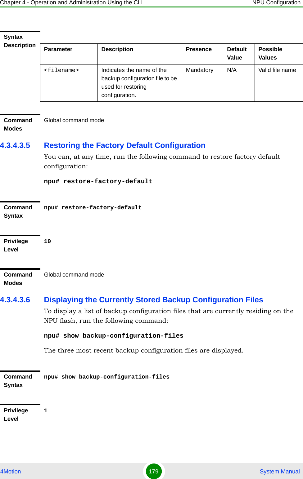
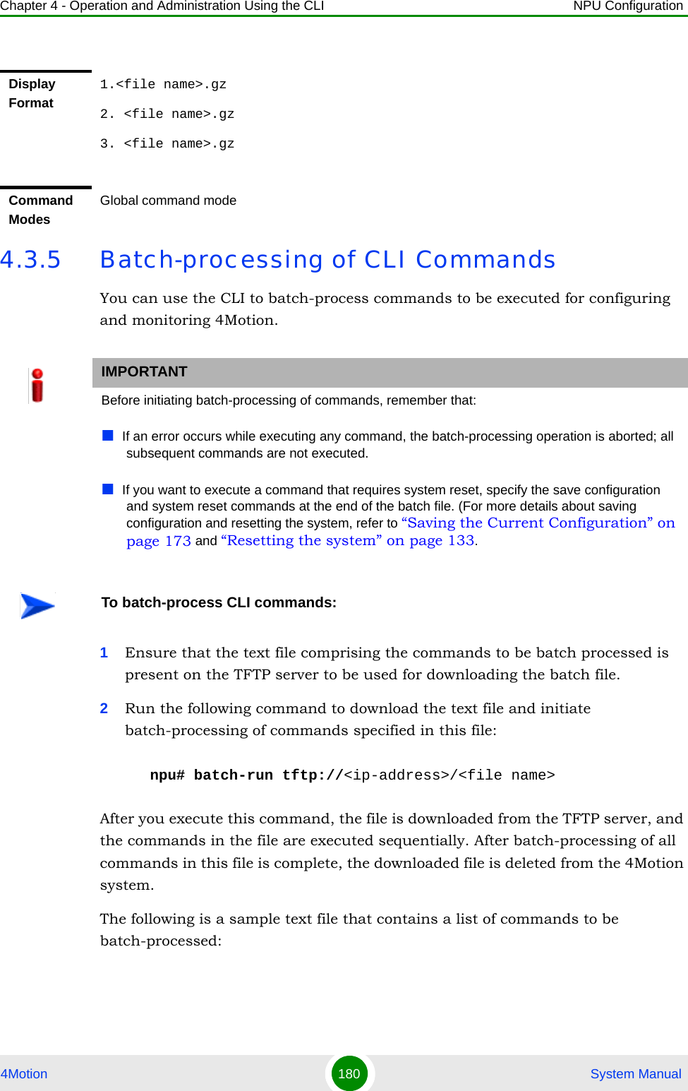
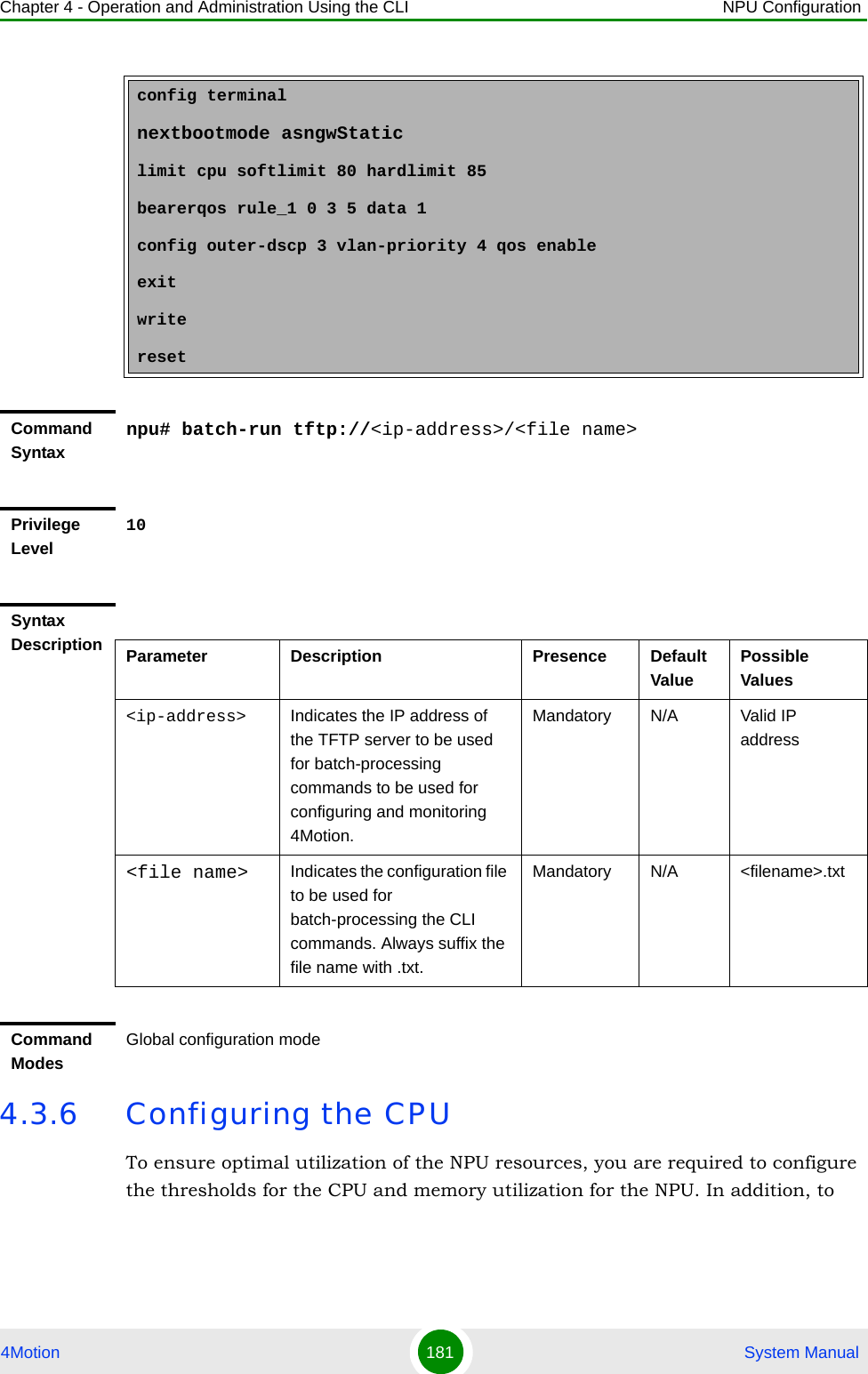
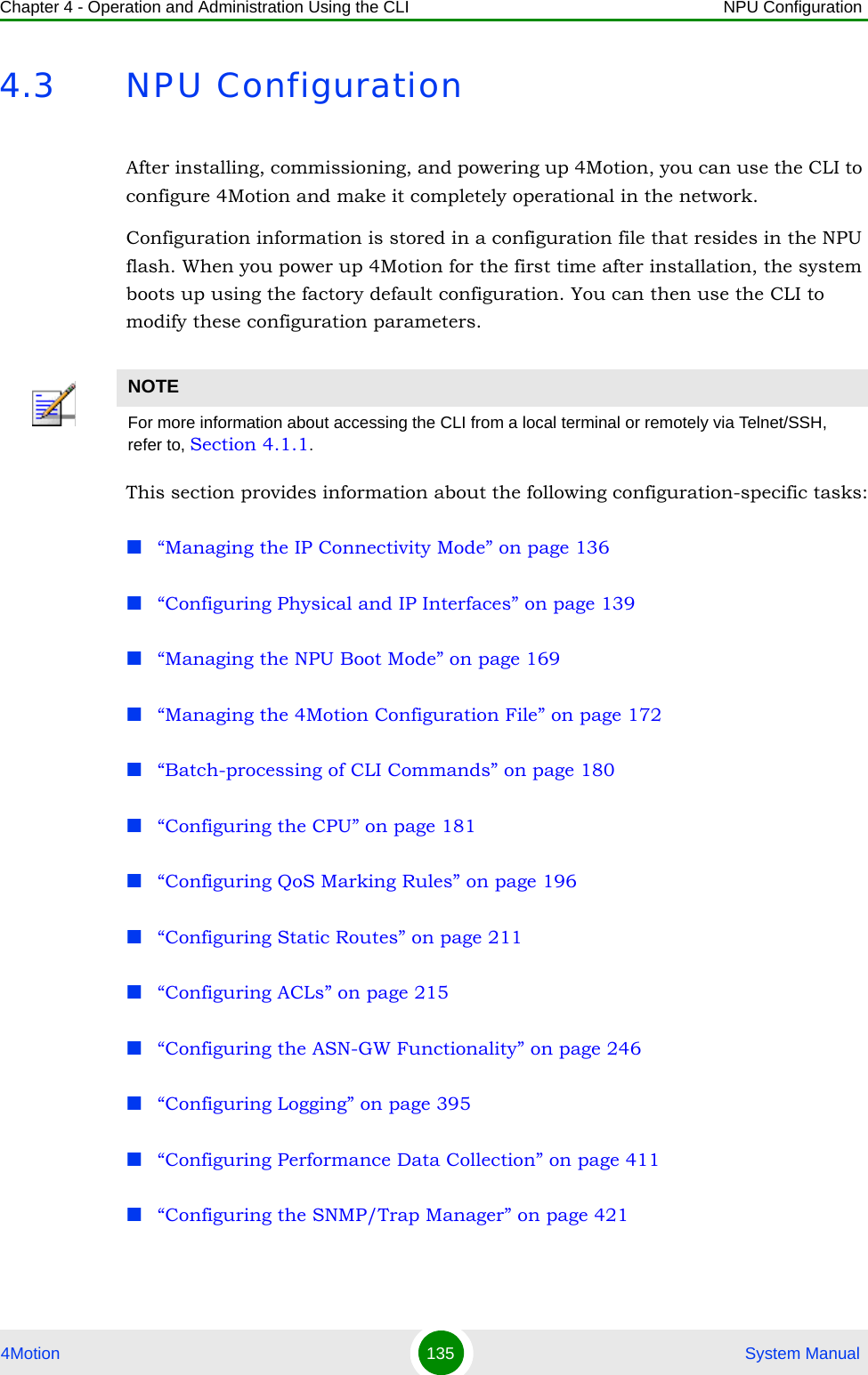
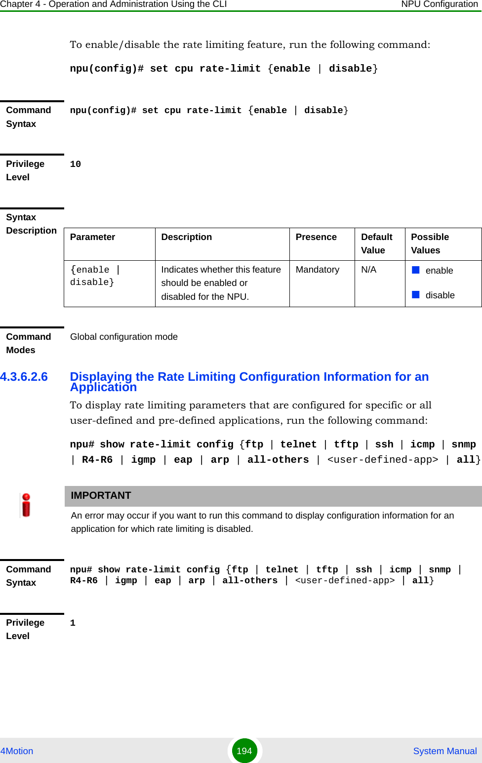
![Chapter 4 - Operation and Administration Using the CLI NPU Configuration4Motion 182 System Manualprotect the from hostile applications, you can limit the type and rate of traffic destined towards the NPU. This section describes the commands to be executed for:“Configuring CPU and Memory Utilization Thresholds for the NPU” on page 182“Configuring the Rate Limiting for the NPU” on page 1844.3.6.1 Configuring CPU and Memory Utilization Thresholds for the NPUThis section describes the commands for:“Specifying Thresholds for CPU and Memory Utilization for the NPU” on page 182“Displaying CPU and Memory Utilization Limits for the NPU” on page 1834.3.6.1.1 Specifying Thresholds for CPU and Memory Utilization for the NPUYou can use the CLI to configure the thresholds (soft and hard limits) for CPU and memory utilization for the NPU. When the soft or hard limit for either CPU or memory utilization is reached, an alarm is raised.To configure the thresholds (soft and hard limits) for CPU and memory utilization for the NPU, run the following command:npu(config)# limit {cpu | memory} ([softlimit <limit>] [hardlimit <limit>])For example, run the following command if you want to configure the soft and hard limits for CPU utilization to be 78 and 85 percent, respectively.npu(config)# limit cpu softlimit 80 hardlimit 85NOTETo display the current thresholds that are configured for CPU and memory utilization for the NPU, refer to Section 4.3.6.1.2.NOTEAn error may occur if the value of the softlimit parameter is higher than the hardlimit parameter.](https://usermanual.wiki/Alvarion-Technologies/BMAX-OR-25.Manual-2/User-Guide-1114030-Page-86.png)
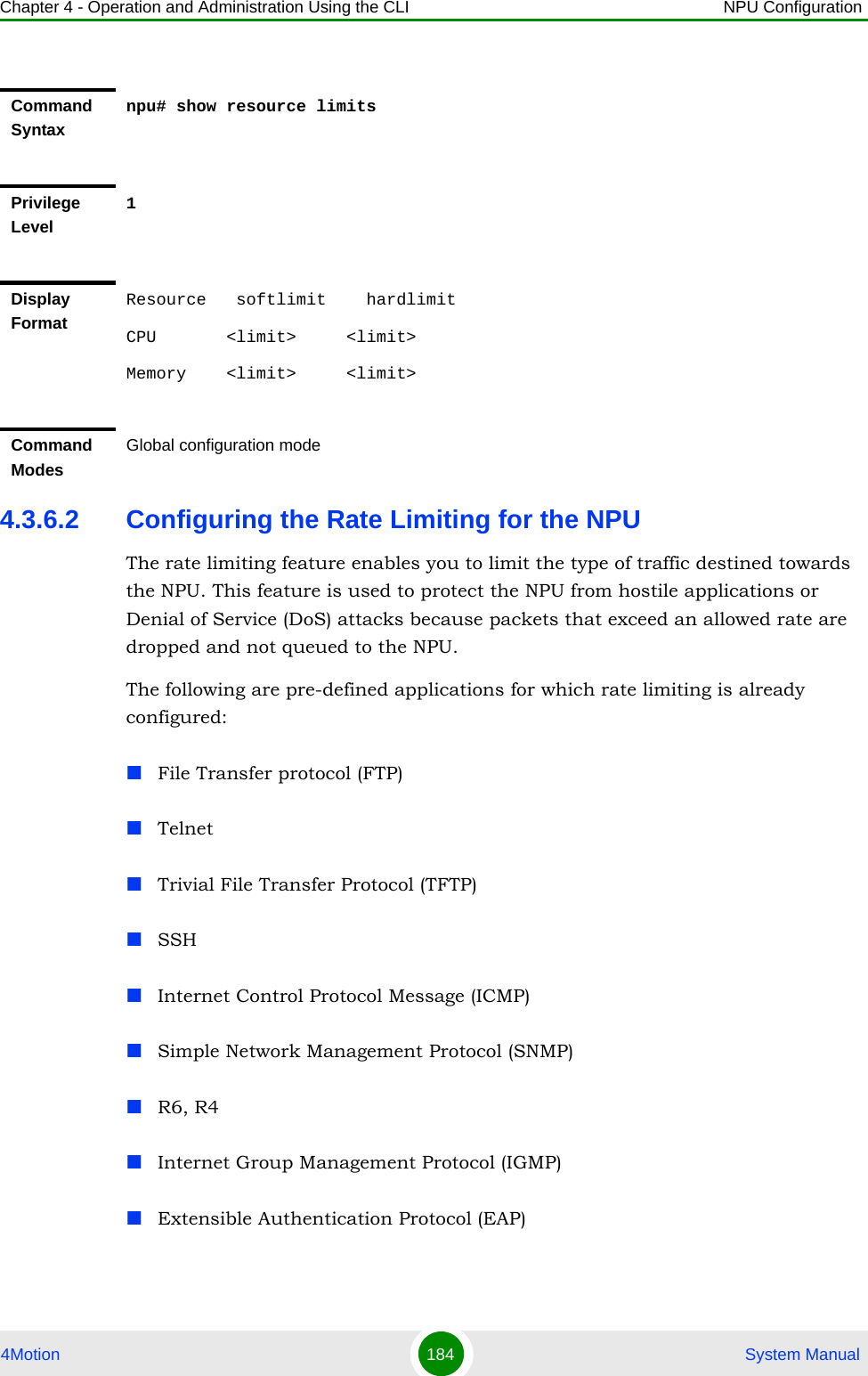
![Chapter 4 - Operation and Administration Using the CLI NPU Configuration4Motion 183 System Manual4.3.6.1.2 Displaying CPU and Memory Utilization Limits for the NPUTo display the configured CPU and memory utilization limits for the NPU, run the following command:npu# show resource limitsCommand Syntaxnpu(config)# limit {cpu | memory} ([softlimit <integer (1-99>] [hardlimit <integer (1-99>])Privilege Level10Syntax Description Parameter Description Presence Default ValuePossible Values{cpu | memory} Indicates whether the threshold is to be specified for CPU or memory utilization.Mandatory N/A cpu/ memory[softlimit <integer (1-99>]Indicates the soft limit, as a percentage, for CPU/memory utilization. When this limit is reached, the system raises a Minor or Major alarm.Optional 70 (for CPU and memory utilization)1-99[hardlimit <integer (1-99>])Indicates the hard limit, as a percentage, for CPU/memory utilization. When this limit is reached, the system raises a Critical alarm.The value of this parameter should always be greater than the softlimit parameter.Optional 90 (for CPU and memory utilization)1-99Command ModesGlobal configuration modeNOTETo configure the CPU and memory utilization limits for the NPU, refer to Section 4.3.6.1.2.](https://usermanual.wiki/Alvarion-Technologies/BMAX-OR-25.Manual-2/User-Guide-1114030-Page-87.png)
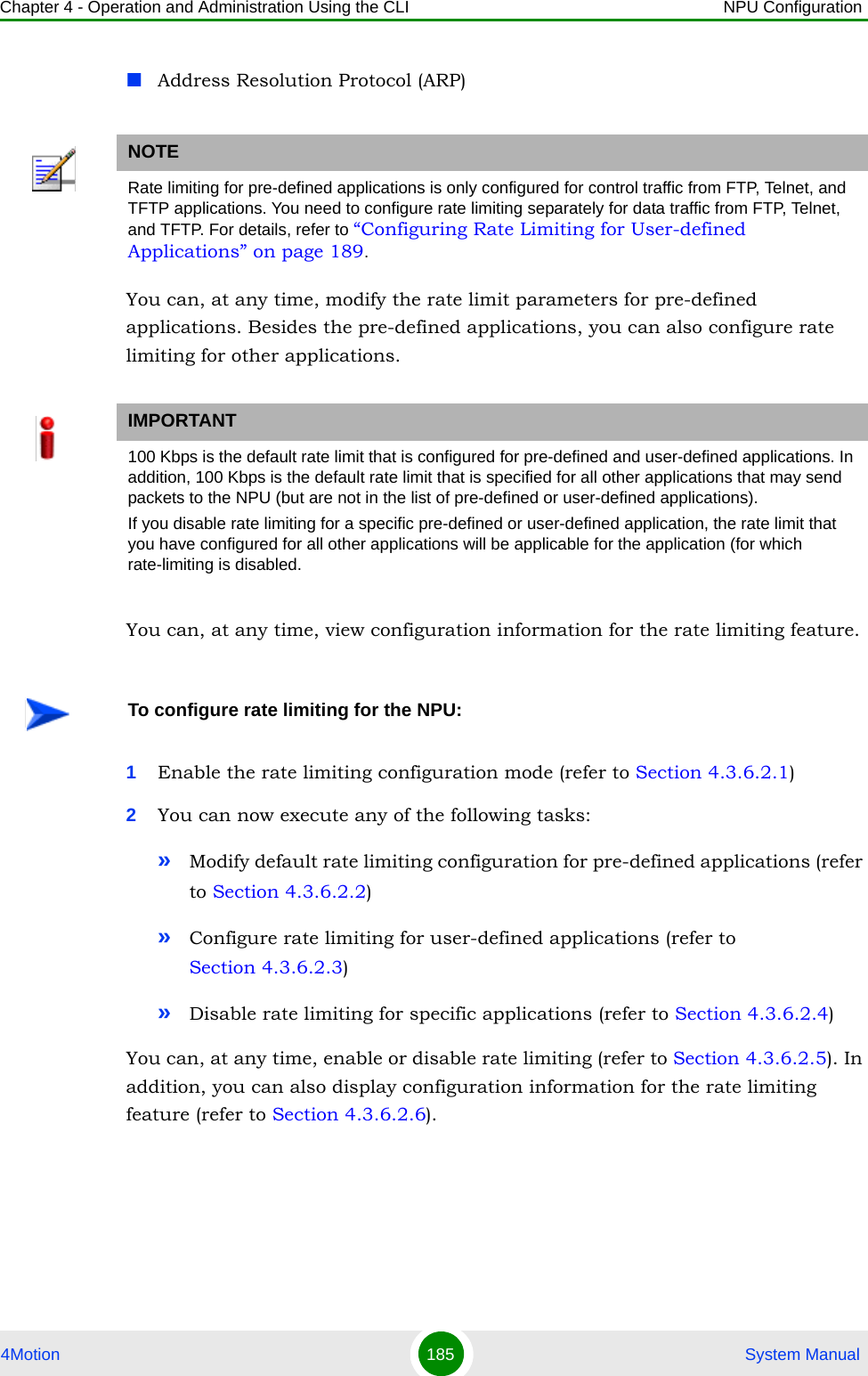
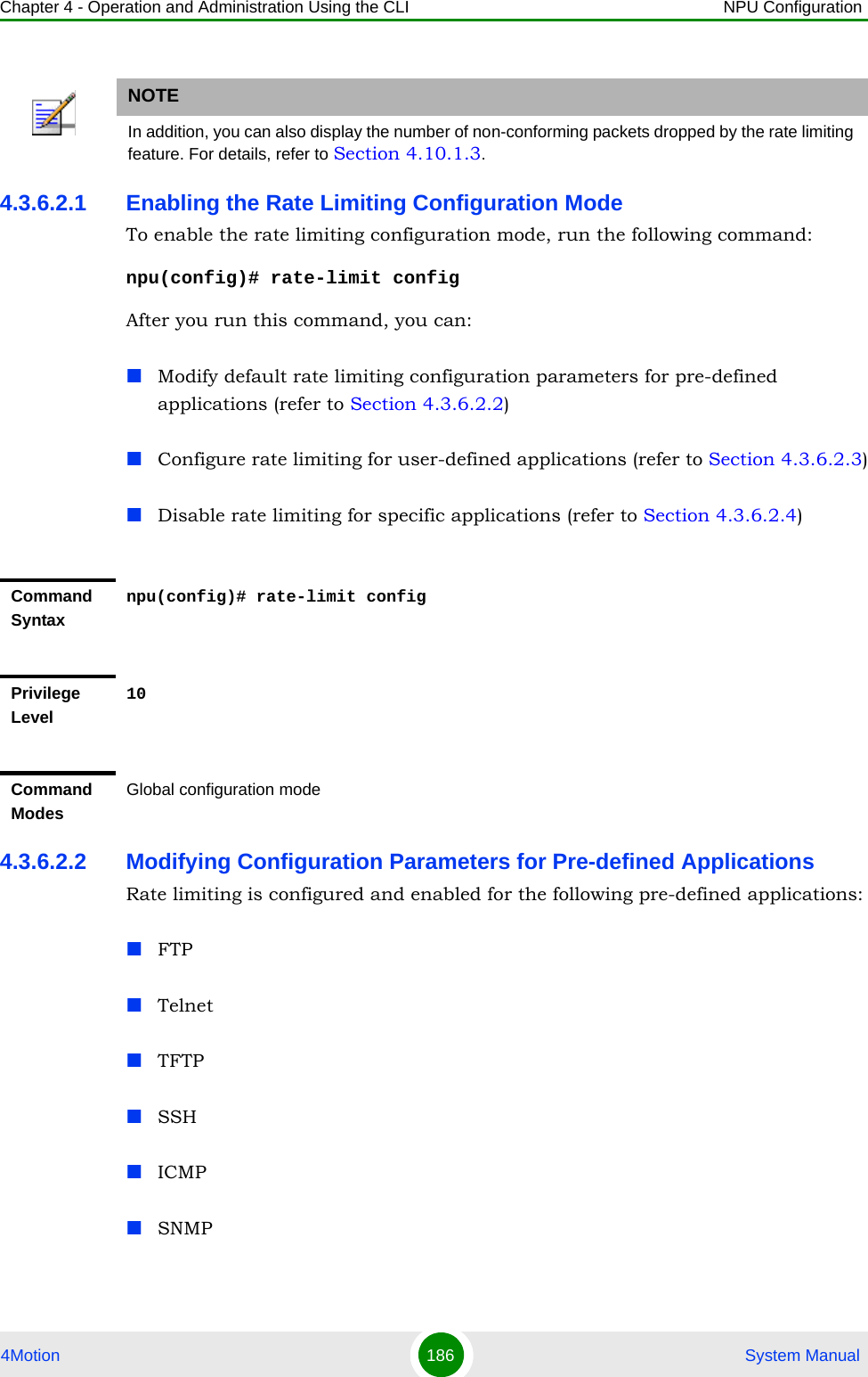
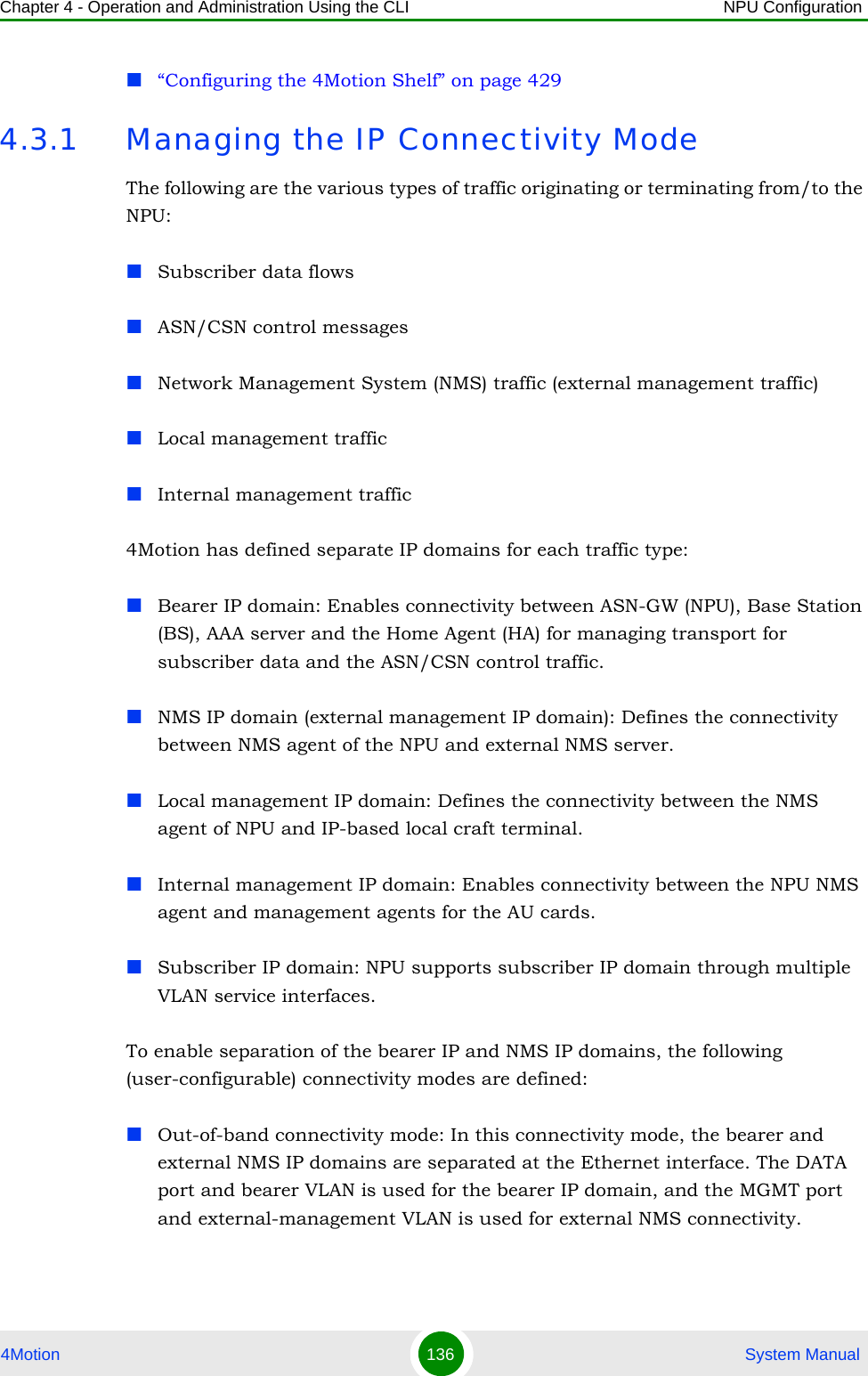
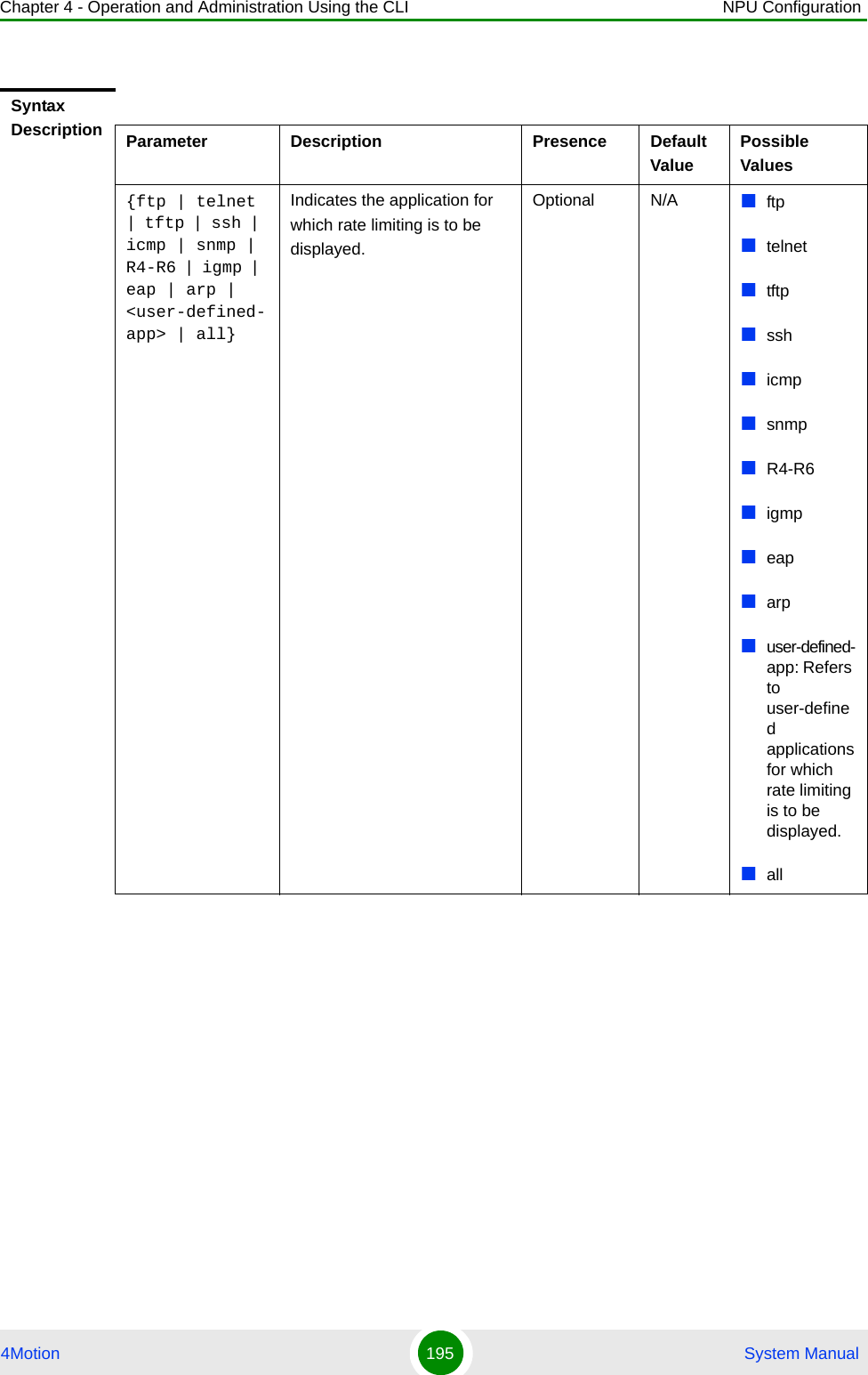
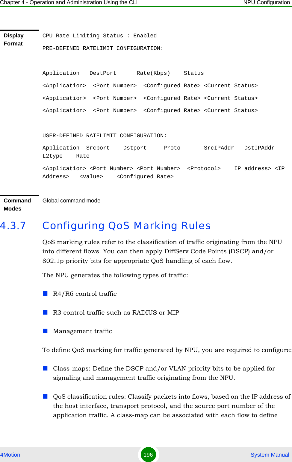
![Chapter 4 - Operation and Administration Using the CLI NPU Configuration4Motion 187 System ManualR6, R4IGMPEAPARPRun the following command to modify the rate limiting configuration parameters for a pre-defined application. You can also use this command to configure rate limiting for all other applications that may send packets to the NPU. npu(config-ratelmt)# set rate-limit {ftp | telnet | tftp | ssh | icmp | snmp | R4-R6 | igmp | eap | arp | all-others} [dstport <port_num>] <rate-Kbps>For example, run the following command to specify that NPU should listen for FTP packets on port 1024 a packet rate of 300 Kbps.npu(config-ratelmt)# set rate-limit ftp dstport 1024 300NOTETo configure user-defined applications, refer to Section 4.3.6.2.3.IMPORTANTRate limiting for pre-defined applications is only configured for control traffic from FTP, Telnet, and TFTP applications. You need to configure rate limiting seaparately for data traffic from FTP, Telnet, and TFTP applications. For details, refer to “Configuring Rate Limiting for User-defined Applications” on page 189.NOTEBy default, the NPU listens for packets from pre-defined applications on standard ports.Command Syntaxnpu(config-ratelmt)# set rate-limit {ftp | telnet | tftp | ssh | icmp | snmp | R4-R6 | igmp | eap | arp | all-others} [dstport <port_num>] <rate-Kbps>Privilege Level10](https://usermanual.wiki/Alvarion-Technologies/BMAX-OR-25.Manual-2/User-Guide-1114030-Page-91.png)
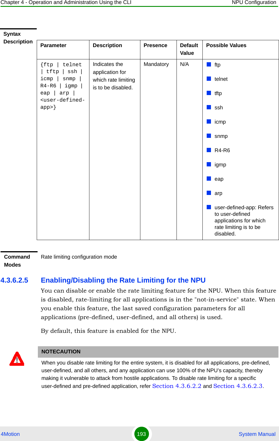
![Chapter 4 - Operation and Administration Using the CLI NPU Configuration4Motion 188 System ManualSyntax Description Parameter Description Presence Default ValuePossible Values{ftp | telnet | tftp | ssh | icmp | snmp | R4-R6 | igmp | eap | arp | all-others}Indicates the application for which the rate limiting is to be configured. Mandatory N/A ftptelnettftpsshicmpsnmpR4-R6igmpeaparpall-others: Refers to all other applications that may send packets to the NPU, and are not in the list of pre-defined or user-defined applications.[dstport <port_num>]Indicates the TCP/UDP port on which the NPU listens for packets from a pre-defined application.Optional Standard ports1-65535[rate-Kbps] Indicates the rate, in Kbps, at which a pre-defined application can send packets to the NPU.Mandatory 100 for all specific applications.1000 for all-others1-1000000](https://usermanual.wiki/Alvarion-Technologies/BMAX-OR-25.Manual-2/User-Guide-1114030-Page-92.png)
![Chapter 4 - Operation and Administration Using the CLI NPU Configuration4Motion 189 System Manual4.3.6.2.3 Configuring Rate Limiting for User-defined ApplicationsBesides the pre-defined applications (refer to Section 4.3.6.2.2), you can also configure other applications that can send packets to the NPU. Run the following command to configure rate limiting for a user-defined application. npu(config-ratelmt)# set rate-limit <user-defined-app> {[srcport <port_num>] [dstport <port_num>] [protocol <protocol_num>] [srcaddr <ip_addr>] [dstaddr <ip_addr>] [ethertype <protocol_num>]} <rate-Kbps>In the above command, it is recommended that you configure at least one of the following parameters. The more parameters you configure, the higher the granularity of the rate limiting definition for that application.L4 source port L4 destination portL3 protocol fieldSource IP addressDestination IP addressL2 protocol type fieldCommand ModesRate limiting configuration modeNOTETo display the rate limiting parameters defined for user-defined and other applications, refer to Section 4.3.6.2.6](https://usermanual.wiki/Alvarion-Technologies/BMAX-OR-25.Manual-2/User-Guide-1114030-Page-93.png)
![Chapter 4 - Operation and Administration Using the CLI NPU Configuration4Motion 190 System ManualIMPORTANTWhile configuring rate limiting for user-defined applications, remember that:Configuration for user-defined applications is applied with respect to the sequence in which you configure these values. It is recommended that you specify the more granular definitions before the less granular ones. For example, if you are creating a definition that configures the source port 200 and destination port 500, create this definition before creating a generic configuration for applications with source port 200. Otherwise, packets with source port 200 and destination port 500 will be limited according to the rate configured for source port 200.Packets are classified and identified by the hardware with respect to the depth of the fields that are configured. Specify the values of the rate limiting parameters for user-defined applications exactly as these appear in the packet header.You cannot modify rate limiting definitions for a user-defined application. To modify rate limiting configuration for a user-defined application, disable and delete that definition, and then create a new one using the command described in this section. To disable an application definition, refer to Section 4.3.6.2.4.L2 protocols cannot be defined with any of the other L4 or L3 fields mentioned above.The destination IP address that you specify should be the IP address that you have configured for the external-management, internal-management, bearer, and local-management interface.IMPORTANTAn error may occur when you run this command and:The destination port, protocol fields, or Ethernet type that you have configured for the user-defined application is identical to the destination port of the pre-defined application.Rate limiting is completely disabled for the NPU.Command Syntaxnpu(config-ratelmt)# set rate-limit <user-defined-app> {[srcport <port_num>] [dstport <port_num>] [protocol <protocol_num>] [srcaddr <ip_addr>] [dstaddr <ip_addr>] [ethertype <protocol_num>]} <rate-Kbps>Privilege Level10Syntax Description Parameter Description Presence Default ValuePossible Values<user-defined-app>Indicates the name of the application.Mandatory N/A String (up to 20 characters)](https://usermanual.wiki/Alvarion-Technologies/BMAX-OR-25.Manual-2/User-Guide-1114030-Page-94.png)
![Chapter 4 - Operation and Administration Using the CLI NPU Configuration4Motion 191 System Manual4.3.6.2.4 Disabling and Deleting Rate Limiting Configuration for an ApplicationTo disable and delete rate limiting configuration for an application, run the following command:[srcport <port_num>]Indicates the L4 source port of the user-defined application. specify the value of this parameter exactly as this field appears in the TCP/UDP header.Optional N/A 1-65535[dstport <port_num>]Indicates the L4 destination port of the user-defined application. This parameter should be specified exactly as it appears in the TCP/UDP header.Optional N/A 1-65535[protocol <protocol_num>]Indicates the L3 protocol field of the user-defined application. This parameter should be specified exactly as it appears in the IP headerOptional N/A 0-255[srcaddr <ip_addr>]Indicates the source IP address of the user-defined application.Optional N/A Valid unicast IP address[dstaddr <ip_addr>]Indicates the pre-configured destination IP address for the NPU for which rate limiting for this user-defined application is to be configured. Specify the IP address that is assigned to the external-management, internal-management, local-management or bearer interface.Optional N/A Valid unicast IP address[ethertype <protocol_num>]Indicates the Ethernet type field of the user-defined L2 protocol.Optional N/A 1536-65535[rate-Kbps] Indicates the rate, in Kbps, at which an application can send packets to the NPU.Mandatory 100 1-1000000 Command ModesRate limiting configuration mode](https://usermanual.wiki/Alvarion-Technologies/BMAX-OR-25.Manual-2/User-Guide-1114030-Page-95.png)
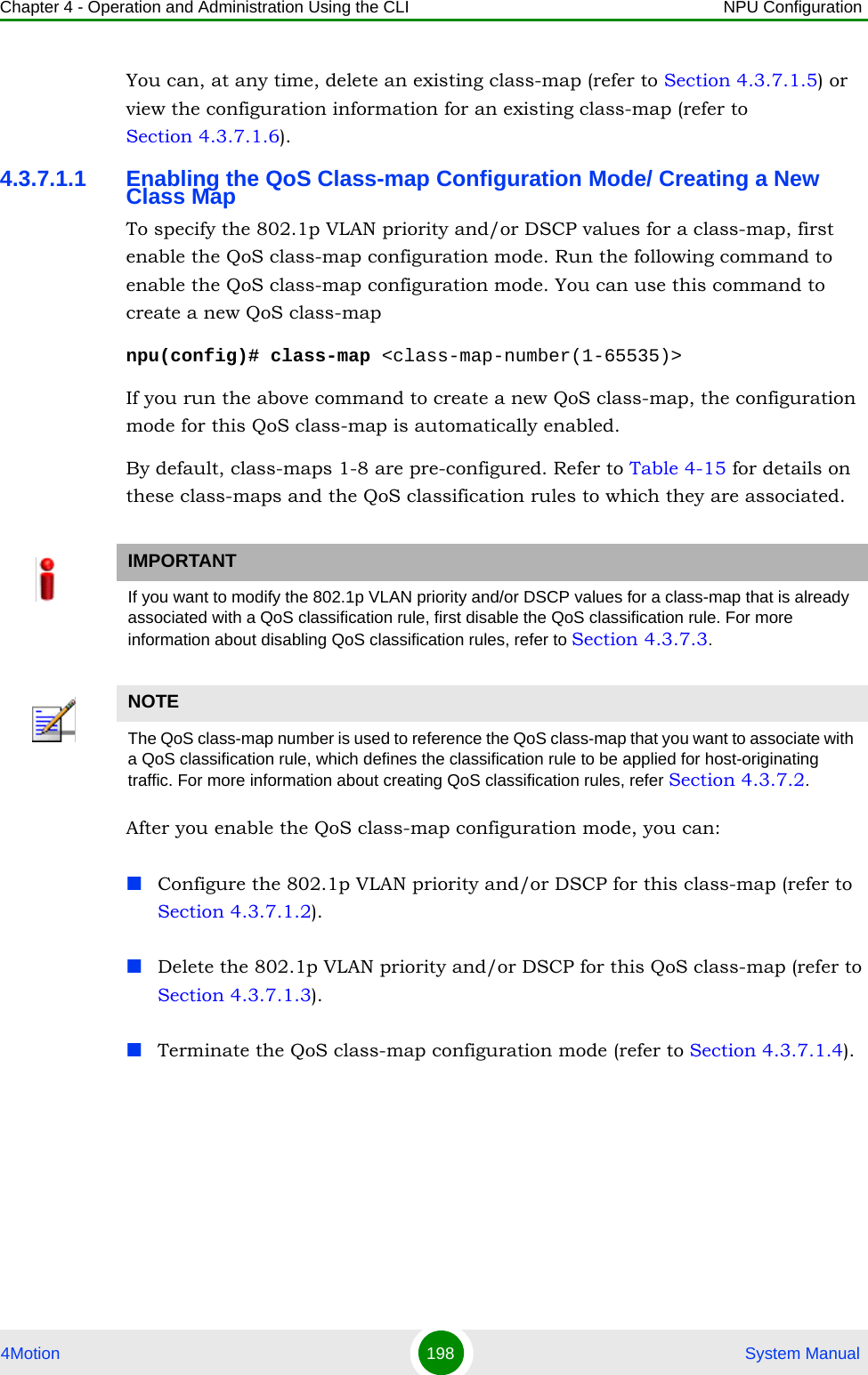
![Chapter 4 - Operation and Administration Using the CLI NPU Configuration4Motion 200 System Manualnpu(config-cmap)# set {[cos <new-cos(0-7)>] [ip dscp <new-dscp(0-63)>]}4.3.7.1.3 Deleting 802.1p and/or DSCP Values from a Class-mapRun the following command to delete the 802.1p VLAN priority and/or DSCP for this class-map.npu(config-cmap)# no {[cos <new-cos(0-7)>] [ip dscp <new-dscp(0-63)>]}Command Syntaxnpu(config-cmap)# set {[cos <new-cos(0-7)>] [ip dscp <new-dscp(0-63)>]}Privilege Level10Syntax Description Parameter Description Presence Default ValuePossible Values[cos <new-cos(0-7)>]Indicates the 802.1p VLAN priority value to be applied for this class-map.Optional N/A 0-7 where 0 is the lowest and 7 is the highest[ip dscp <new-dscp(0-63)>]Indicates the DSCP value to be applied for this class-map.Optional N/A 0-63Command ModesClass-map configuration modeIMPORTANTIf you are deleting the 802.1p VLAN priority and/or DSCP for a class-map that is associated with a QoS classification rule, first disable the QoS classification rules for that ACL. For details, refer to Section 4.3.7.3.IMPORTANTAn error may occur if the 802.1p or DSCP that you have specified do not exist for this class-map.Command Syntaxnpu(config-cmap)# no {[cos <new-cos(0-7)>] [ip dscp <new-dscp(0-63)>]}](https://usermanual.wiki/Alvarion-Technologies/BMAX-OR-25.Manual-2/User-Guide-1114030-Page-104.png)
![Chapter 4 - Operation and Administration Using the CLI NPU Configuration4Motion 201 System Manual4.3.7.1.4 Terminating the QoS Class-map Configuration ModeTo terminate the QoS class-map configuration mode, run the following command:npu(config-cmap)# exit4.3.7.1.5 Deleting a QoS Class-mapRun the following command to delete an existing QoS class-map:npu(config)# no class-map <class-map-number(1-65535)>Privilege Level10Syntax Description Parameter Description Presence Default ValuePossible Values[cos <new-cos(0-7)>]Indicates the 802.1p VLAN priority to be deleted for this class-map.Optional N/A 0-7[ip dscp <new-dscp(0-63)>]Indicates the DSCP to be deleted for this class-map.Optional N/A 0-63Command ModesQoS class-map configuration modeCommand Syntaxnpu(config-cmap)# exitPrivilege Level10Command ModesQoS class-map configuration modeIMPORTANTAn error may occur if you specify a class-map number that does not exist or is not within the range, 1-65535.](https://usermanual.wiki/Alvarion-Technologies/BMAX-OR-25.Manual-2/User-Guide-1114030-Page-105.png)
![Chapter 4 - Operation and Administration Using the CLI NPU Configuration4Motion 202 System Manual4.3.7.1.6 Displaying Configuration Information for a Class-mapRun the following command to view the configuration information for a class-map:npu# show class-map [<class-map-num(1-65535)>]Specify the class-map number if you want to view configuration information for a specific class-map. If you do not specify the class-map number, configuration information for all class-maps is displayed.Command Syntaxnpu(config)# no class-map <class-map-number(1-65535)>Privilege Level10Syntax Description Parameter Description Presence Default ValuePossible Values<class-map-number(1-65535)>Indicates the identifier of the QoS class-map number to be deleted.Mandatory N/A 1-65535Command ModesGlobal configuration modeIMPORTANTAn error may occur if you specify a class-map number that does not exist or is not within the range, 1-65535.Command Syntaxnpu# show class-map [<class-map-num(1-65535)>]Privilege Level1](https://usermanual.wiki/Alvarion-Technologies/BMAX-OR-25.Manual-2/User-Guide-1114030-Page-106.png)
![Chapter 4 - Operation and Administration Using the CLI NPU Configuration4Motion 203 System Manual4.3.7.2 Managing QoS Classification RulesQoS classification rules classify packets into flows, based on the following parameters:IP address of the host originating the traffic (the IP address assigned to the bearer, internal-management or external-management interface)Layer 3 protocol indicating either TCP or UDPLayer 4-source port for the application that needs to be marked (for example, FTP, Telnet, SNMP, MIP, or RADIUS)A class-map can be associated with each flow to define separate DSCP and/or VLAN priority bits for QoS handling of each flow. 1Enable the ACL configuration mode for ACL 199 (refer to Section 4.3.7.2.1).Syntax Description Parameter Description Presence Default ValuePossible Values[<class-map-num(1-65535)>]Indicates the identifier of the class-map for which configuration information is to be displayed. Do not specify a value for this parameter if you want to view the configuration information for all class-maps.Optional N/A 1-65535Display Format (for each class-map if requested for all class-maps)Class map <class map number>----------------------------------------------CoS Value : <value>DSCP Value : <value>Command ModesGlobal command modeTo configure a QoS classification rule:](https://usermanual.wiki/Alvarion-Technologies/BMAX-OR-25.Manual-2/User-Guide-1114030-Page-107.png)
![Chapter 4 - Operation and Administration Using the CLI NPU Configuration4Motion 204 System Manual2You can now:»Configure one or more QoS classification rules (refer to Section 4.3.7.2.2)»Delete one or more QoS classification rules (refer to Section 4.3.7.2.3)»Terminate the ACL configuration mode (refer to Section 4.3.7.2.4)You can, at any time, enable/disable QoS marking (refer to Section 4.3.7.3) or view the configuration information for ACL 199 (refer to Section 4.3.7.4).4.3.7.2.1 Enabling the ACL Configuration Mode for ACL 199To configure QoS classification rules for host-originating traffic, first enable the extended ACL 199 configuration mode.Run the following command to enable the extended ACL configuration mode for ACL 199. npu(config)# ip access-list {standard <access-list-number (1-99)> | extended <access-list-number (100-199)>} [name<string>]After you enable the ACL 199 configuration mode, you can one or several QoS classification rules, and associate them with the appropriate class-maps.IMPORTANTQoS classification rules can be associated only with ACL 199.IMPORTANTQoS classification rules can be added only to extended ACL 199Command Syntaxnpu(config)# ip access-list {standard <access-list-number (1-99)> | extended <access-list-number (100-199)>} [name <string>]Privilege Level10](https://usermanual.wiki/Alvarion-Technologies/BMAX-OR-25.Manual-2/User-Guide-1114030-Page-108.png)
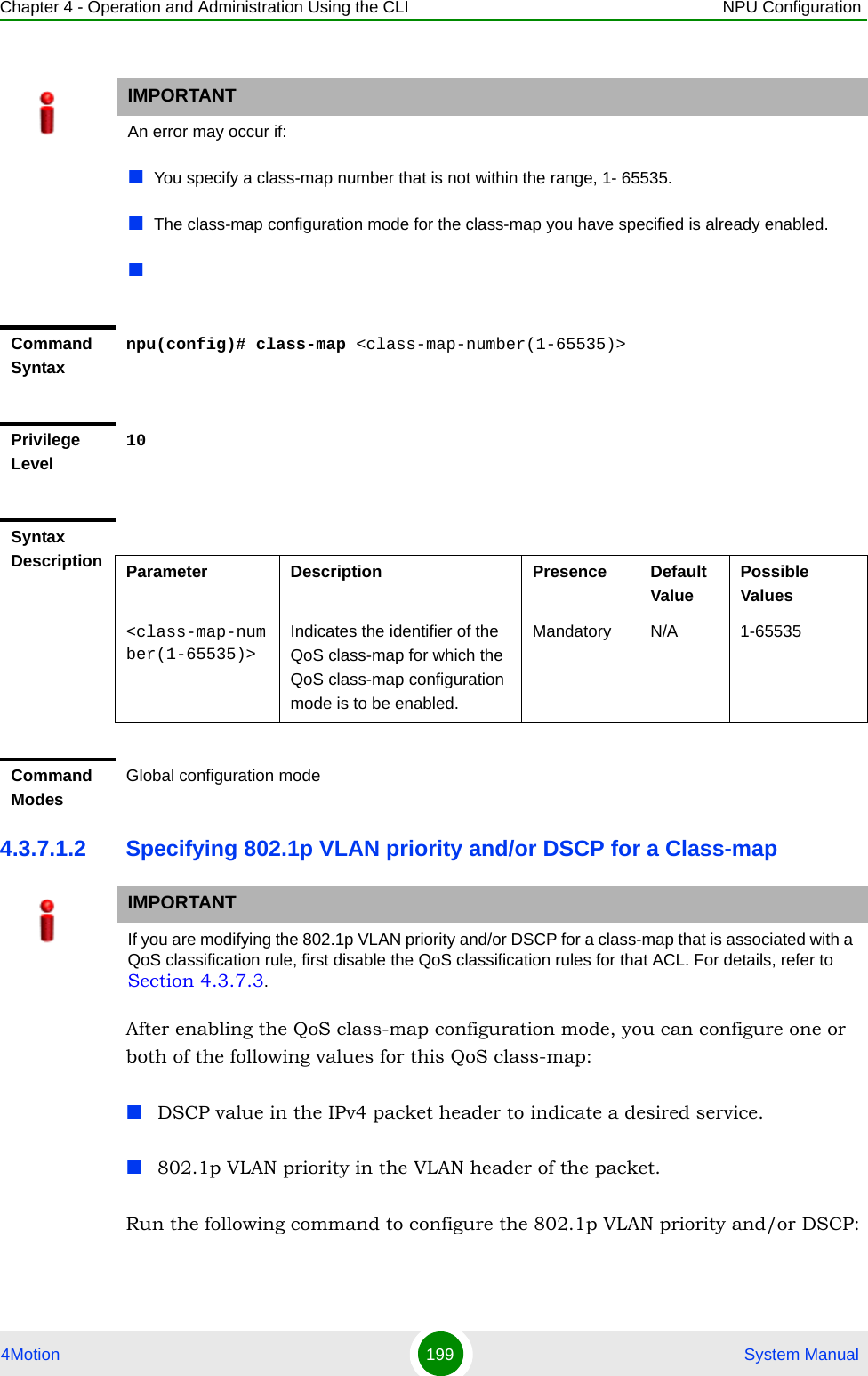
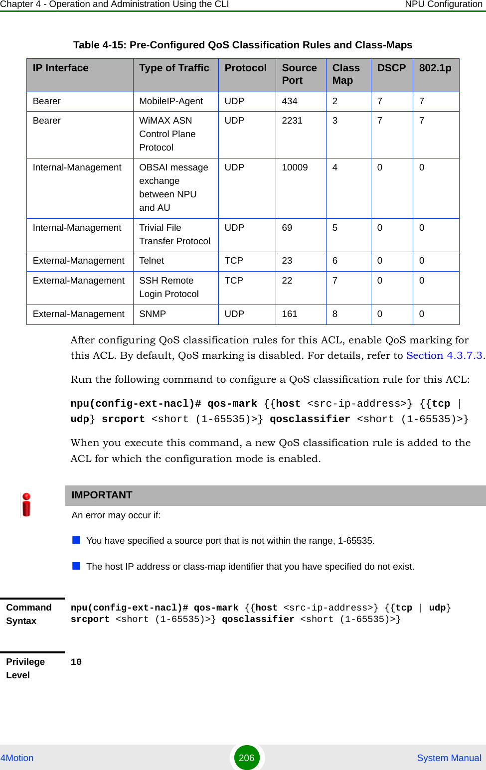
![Chapter 4 - Operation and Administration Using the CLI NPU Configuration4Motion 205 System Manual4.3.7.2.2 Configuring a QoS Classification RuleYou can configure the QoS classification rules for the ACL with respect the following parameters:Source IP address for the host-originating application trafficApplication protocol (TCP or UDP)L4 source port of the application trafficQoS class-map identifier By default, there are 8 pre-configured QoS classification rules associated with the 8 pre-configured QoS class-maps:Syntax Description Parameter Description Presence Default ValuePossible Valuesextended <access-list-number (100-199)>Indicates the identifier of the extended ACL for which the ACL configuration mode is to be enabled. You must specify 199 to enable configuration of QoS classification rules.Mandatory N/A 199[name <string>]Indicates the name of the ACL for which the ACL configuration mode is to be enabled. Note: If you do not specify the ACL name, the ACL number is used as the default ACL name.Optional N/A String (upto 20 characters)Command ModesGlobal configuration modeTable 4-15: Pre-Configured QoS Classification Rules and Class-MapsIP Interface Type of Traffic Protocol Source Port Class Map DSCP 802.1p Bearer RADIUS UDP 1812 1 7 7](https://usermanual.wiki/Alvarion-Technologies/BMAX-OR-25.Manual-2/User-Guide-1114030-Page-109.png)
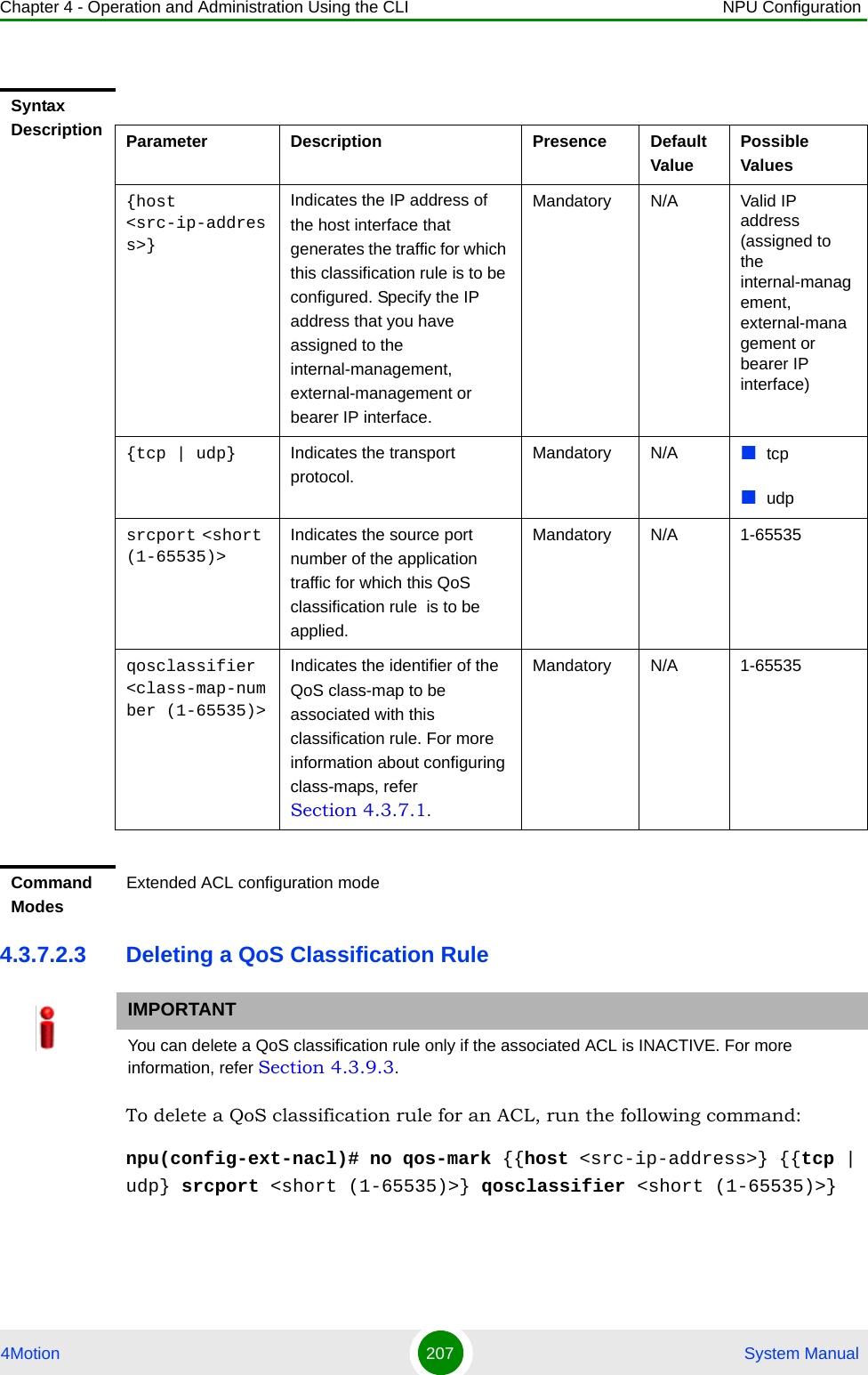
![Chapter 4 - Operation and Administration Using the CLI NPU Configuration4Motion 208 System ManualWhen you execute this command, the QoS classification rule is deleted from the ACL. IMPORTANTAn error may occur if you specify a combination of parameters that do not match any of the existing QoS classification rules.:Command Syntaxnpu(config-ext-nacl)# no qos-mark {{host <src-ip-address>} {{tcp | udp} srcport <short (1-65535)>} qosclassifier <short (1-65535)>}Privilege Level10Syntax Description Parameter Description Presence Default ValuePossible Values[host <src-ip-address>]Indicates the IP address of the host interface that generates the traffic for which this classification rule is to be deleted.Mandatory N/A Valid IP address (assigned to the internal-management, external-management or bearer IP interface){tcp | udp} Indicates the transport protocol.Mandatory N/A tcpudpsrcport <short (1-65535)>Indicates the source port number of the application traffic for which this QoS classification rule is to be deleted.Mandatory N/A 1-65535qosclassifier <class-map-number (1-65535)>Indicates the identifier of the QoS class-map associated with the classification rule to be deleted. For more information about class-maps, refer Section 4.3.7.1.Mandatory N/A 1-65535](https://usermanual.wiki/Alvarion-Technologies/BMAX-OR-25.Manual-2/User-Guide-1114030-Page-112.png)
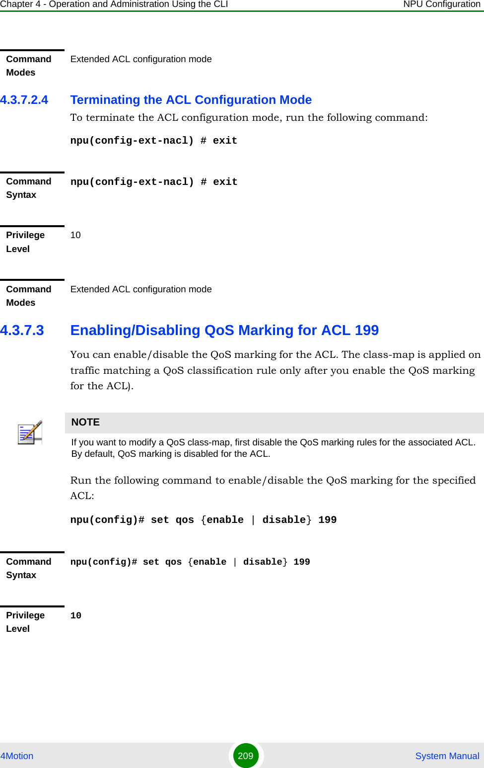
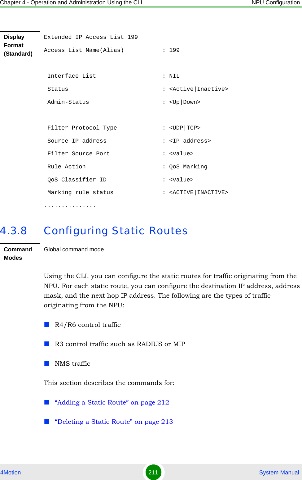
![Chapter 4 - Operation and Administration Using the CLI NPU Configuration4Motion 210 System Manual4.3.7.4 Displaying ACL 199 Configuration InformationRun the following command to display the configuration information for ACL 199:npu# show access-lists [{199 | <access-list-199-name}]Syntax Description Parameter Description Presence Default ValuePossible Values{enable | disable}Indicates whether QoS marking should be enabled or disabled for a specific ACL.Mandatory disable enabledisable199 Indicates the identifier of the ACL for which the QoS marking is to be activated. You musr specify 199.Mandatory N/A 199Command ModesGlobal configuration modeIMPORTANTAn error may occur if the ACL name you have specified does not exist.Command Syntaxnpu# show access-lists [199| <access-list-199-name}]Privilege Level1Syntax Description Parameter Description Presence Default ValuePossible Values[199 | <access-list-199-name}]To view configuration information for ACL 199, specify 199 or the name configured for this ACL.Mandatory for viewing information for ACL 199.N/A 199String; the name configured for ACL 199.](https://usermanual.wiki/Alvarion-Technologies/BMAX-OR-25.Manual-2/User-Guide-1114030-Page-114.png)
![Chapter 4 - Operation and Administration Using the CLI NPU Configuration4Motion 217 System Manual4After you have configured the ACL, you can attach the ACL with the AUs or NPU refer Section 4.3.9.3.4.3.9.1.1 Enable the ACL Configuration Mode/Creating an ACLTo configure an ACL, first enable either of the following ACL configuration modes: StandardExtendedTo apply this ACL to traffic destined towards the AUs or the NPU, you are required to activate this ACL. (for details refer Section 4.3.9.3). Run the following command to enable the ACL configuration mode. You can also use this command to create a new ACL.npu(config)# ip access-list {standard <access-list-number (1-99)> | extended <access-list-number (100-199)>}[name<string>]When you run this command, the ACL configuration mode for the newly-created ACL is automatically enabled. If the name is not specified when creating a new ACL, the default name will be the specified ACL number.For example, run the following command to create ACL 22 in the standard mode:npu(config)# ip access-list standard 22Standard ACL 22 will be created with the default name 22.For example, run the following command to create ACL 111 in the extended mode, with the name ACL-111:npu(config)# ip access-list extended 111 ACL-111After you create an ACL or enable the ACL configuration mode, you canConfigure the ACL in the standard mode (refer Section 4.3.9.1.2)IMPORTANTACL 199 is the default extended ACL that is pre-configured in the system, and is not attached to any interface, that is, it is INACTIVE. However, ACL 199 is reserved for QoS classification rules. You cannot configure Permit/Deny rules for ACL 199.To view the default configuration information for ACL 199, you can run the following command:npu# show access-lists 199For details on using ACL 199 refer to Section 4.3.7.](https://usermanual.wiki/Alvarion-Technologies/BMAX-OR-25.Manual-2/User-Guide-1114030-Page-121.png)
![Chapter 4 - Operation and Administration Using the CLI NPU Configuration4Motion 218 System ManualConfiguring the ACL in the extended mode (refer Section 4.3.9.1.3)IMPORTANTAn error may occur if:·You specify an invalid ACL number. The ACL number should be between 1 and 99 in the standard mode, and between 100 and 199 in the extended mode.The ACL name you have specified is already used for another ACL or is more than 20 characters.Command Syntaxnpu(config)# ip access-list {standard <access-list-number (1-99)> | extended <access-list-number (100-199)>}[name<string>]Privilege Level10Syntax Description Parameter Description Presence Default ValuePossible Valuesstandard <access-list-number (1-99)> | extended <access-list-number (100-199)>Denotes the number of the standard or extended ACL that is to be created or for which the ACL configuration mode is to be enabled. If you are creating a new ACL, the ACL configuration mode is automatically enabled when you execute this command.Note: ACL 199 is reserved for QoS classification rules and cannot be used for creating Permit/Deny rules.Mandatory N/A standard 1-99extended (100-198)[name<string>] Indicates the name of the ACL to be created or for which the ACL configuration mode is to be enabled. Optional ACL nameString (upto 20 characters)Command ModesGlobal configuration mode](https://usermanual.wiki/Alvarion-Technologies/BMAX-OR-25.Manual-2/User-Guide-1114030-Page-122.png)
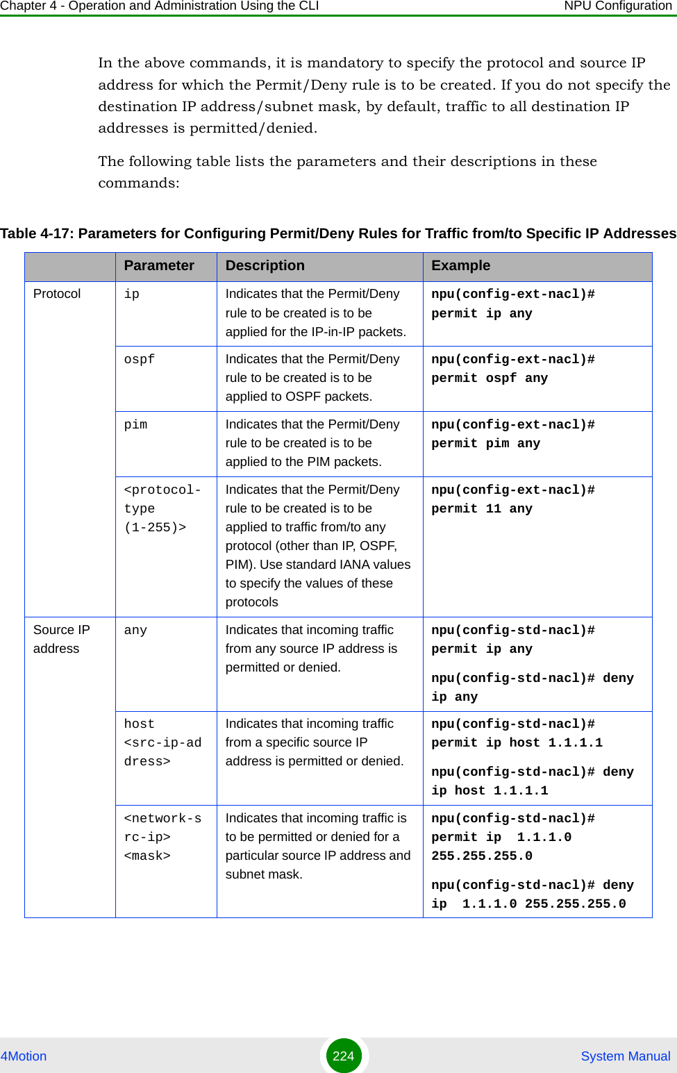
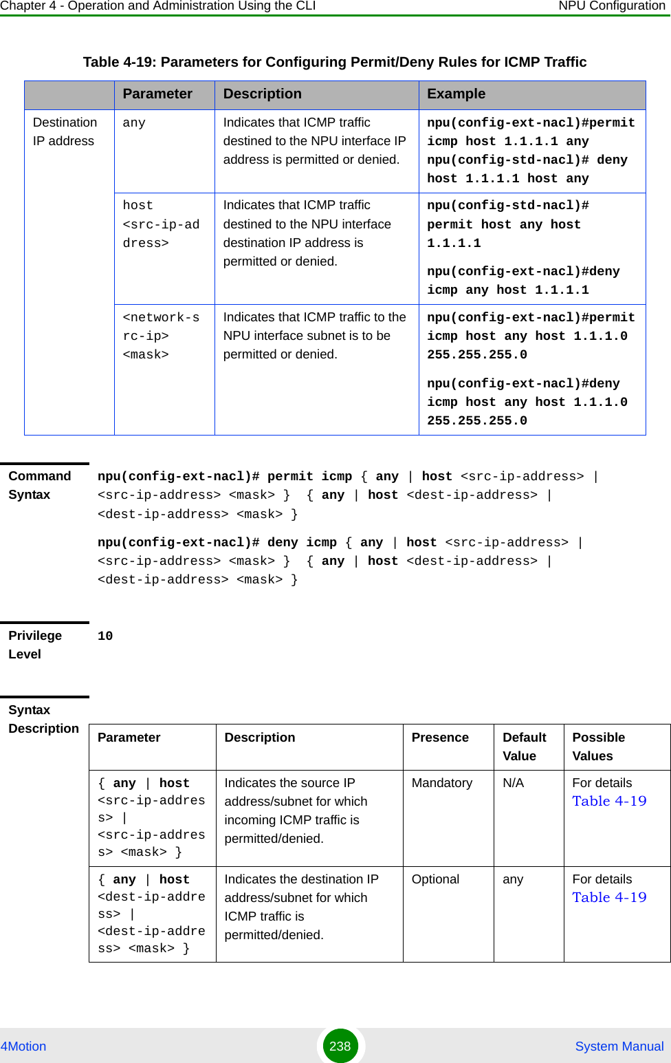
![Chapter 4 - Operation and Administration Using the CLI NPU Configuration4Motion 219 System Manual4.3.9.1.2 Configuring ACLs in the Standard ModeAfter you have enabled the standard ACL configuration mode, you can create or delete the Permit/Deny rules for forwarding traffic from/to a particular source/destination IP address.To enable initial access to the NPU, the Standard ACL 1 is available by default, with a Permit rule allowing unrestricted access to the Local Management interface (Destination IP Address = 172.31.0.1, Source IP Address = Any).This section describes the commands for:“Creating a Permit/Deny Rule (Standard Mode)” on page 219“Deleting a Permit/Deny Rule (Standard Mode)” on page 2214.3.9.1.2.1 Creating a Permit/Deny Rule (Standard Mode)Run the following commands to create the Permit/Deny rules for forwarding traffic from/to a particular source/destination IP address:npu(config-std-nacl)# permit {any | host <src-ip-address> | <network-src-ip> <mask>} [{any | host <dest-ip-address> | <network-dest-ip> <mask>}]npu(config-std-nacl)# deny {any | host <src-ip-address> | <network-src-ip> <mask>} [{any | host <dest-ip-address> | <network-dest-ip> <mask>}] The following table lists the parameters and their descriptions in these commands.IMPORTANTYou cannot create Permit or Deny rules for an ACL that is associated with a Qos marking rule. You can either associate QoS marking rules or permit/deny rules with an ACL.IMPORTANTAfter you have configured the rules to be applied on an ACL, you can attach the ACL to the NPU or AUs. The ACL enables filtering of traffic destined to these interfaces. For more information, refer to Section 4.3.9.3.IMPORTANTIn the above commands, it is mandatory to specify the source IP address for which the Permit/Deny rule is to be created. If you do not specify the destination IP address/subnet mask, by default, traffic to all destination IP addresses configured for the NPU is permitted/denied.](https://usermanual.wiki/Alvarion-Technologies/BMAX-OR-25.Manual-2/User-Guide-1114030-Page-123.png)
![Chapter 4 - Operation and Administration Using the CLI NPU Configuration4Motion 220 System ManualTable 4-16: Parameters for Configuring Permit/Deny Rules in the Standard ACL ModeParameter Description ExampleSource IP any Indicates that incoming traffic from any source IP address is permitted or denied.npu(config-std-nacl)# permit anynpu(config-std-nacl)# deny anyhost <src-ip-address>Indicates that incoming traffic from a specific source IP address is permitted or denied. npu(config-std-nacl)# permit host 1.1.1.1npu(config-std-nacl)# deny host 1.1.1.1<network-src-ip> <mask>Indicates that incoming traffic is to be permitted or denied for a particular subnet.npu(config-std-nacl)# permit 1.1.1.0 255.255.255.0npu(config-std-nacl)# deny 1.1.1.0 255.255.255.0Destination IP addressany Indicates that traffic destined to all NPU IP addresses is permitted or denied.npu(config-std-nacl)# permit host 1.1.1.1 anynpu(config-std-nacl)# deny host 1.1.1.1 anyhost <src-ip-address>Indicates that traffic destined to a specific destination IP address is permitted or denied. npu(config-std-nacl)# permit any host 1.1.1.1npu(config-std-nacl)# deny any host 1.1.1.1<network-src-ip> <mask>Indicates that traffic destined to a particular subnet is to be permitted or denied.npu(config-std-nacl)# permit any 1.1.1.0 255.255.255.0npu(config-std-nacl)# deny any 1.1.1.0 255.255.255.0Command Syntaxnpu(config-std-nacl)# permit { any | host <src-ip-address> | <network-src-ip> <mask> } [ { any | host <dest-ip-address> | <network-dest-ip> <mask> } ]npu(config-std-nacl)# deny { any | host <src-ip-address> | <network-src-ip> <mask> } [ { any | host <dest-ip-address> | <network-dest-ip> <mask> } ]](https://usermanual.wiki/Alvarion-Technologies/BMAX-OR-25.Manual-2/User-Guide-1114030-Page-124.png)
![Chapter 4 - Operation and Administration Using the CLI NPU Configuration4Motion 221 System Manual4.3.9.1.2.2 Deleting a Permit/Deny Rule (Standard Mode)Run the following commands to delete the Permit/Deny rule for incoming traffic from/to a specific IP address/subnet.npu(config-std-nacl)# no permit {any | host <src-ip-address> | <network-src-ip> <mask>} [{any | host <dest-ip-address> | <network-dest-ip> <mask>}]npu(config-std-nacl)# no deny {any | host <src-ip-address> | <network-src-ip> <mask>} [{any | host <dest-ip-address> | <network-dest-ip> <mask>}] Syntax Description Parameter Description Presence Default ValuePossible Values{ any | host <src-ip-address> | <network-src-ip> <mask> }Indicates the source IP address/subnet for which incoming traffic is permitted/denied.Mandatory N/A For details, refer Table 4-16 [ { any | host <dest-ip-address> | <network-dest-ip> <mask> } ]Indicates the destination IP address/subnet for which traffic is permitted/denied Optional any For details, refer Table 4-16Command ModesStandard ACL configuration modeCommand Syntaxnpu(config-std-nacl)# no permit { any | host <src-ip-address> | <network-src-ip> <mask> } [ { any | host <dest-ip-address> | <network-dest-ip> <mask> } ]npu(config-std-nacl)# no deny { any | host <src-ip-address> | <network-src-ip> <mask> } [ { any | host <dest-ip-address> | <network-dest-ip> <mask> } ] Privilege Level10](https://usermanual.wiki/Alvarion-Technologies/BMAX-OR-25.Manual-2/User-Guide-1114030-Page-125.png)
![Chapter 4 - Operation and Administration Using the CLI NPU Configuration4Motion 222 System Manual4.3.9.1.3 Configuring ACLs in the Extended ModeAfter you have enabled the extended ACL configuration mode, you can create Permit/Deny rules based on source/destination IP address, protocol and source/destination port numbers.This section describes the commands to be used for:“Configuring Permit/Deny Rules from/to a Specific Protocol and Source/Destination IP Addresses” on page 223“Configuring Permit/Deny Rules for TCP/UDP Traffic” on page 227“Configuring Permit/Deny Rules for ICMP Traffic” on page 236Syntax Description Parameter Description Presence Default ValuePossible Values{ any | host <src-ip-address> | <network-src-ip> <mask> }Indicates the source IP address/subnet for which the Permit/Deny rule is to be deleted.Mandatory N/A For details, refer Table 4-16 [ { any | host <dest-ip-address> | <network-dest-ip> <mask> } ]Indicates the destination IP address/subnet for which the Permit/Deny rule is to be deleted.Optional any For details, refer Table 4-16Command ModesStandard ACL configuration modeIMPORTANTYou cannot create Permit or Deny rules for an ACL that is associated with a Qos marking rule. You can either associate QoS marking rules or permit/deny rules with an ACL.IMPORTANTAfter you have configured the rules to be applied on an ACL, you can attach the ACL to the NPU or AUs. The ACL enables filtering of traffic destined to these interfaces. For more information, refer to Section 4.3.9.3.](https://usermanual.wiki/Alvarion-Technologies/BMAX-OR-25.Manual-2/User-Guide-1114030-Page-126.png)
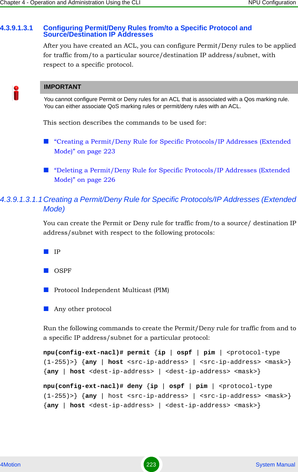
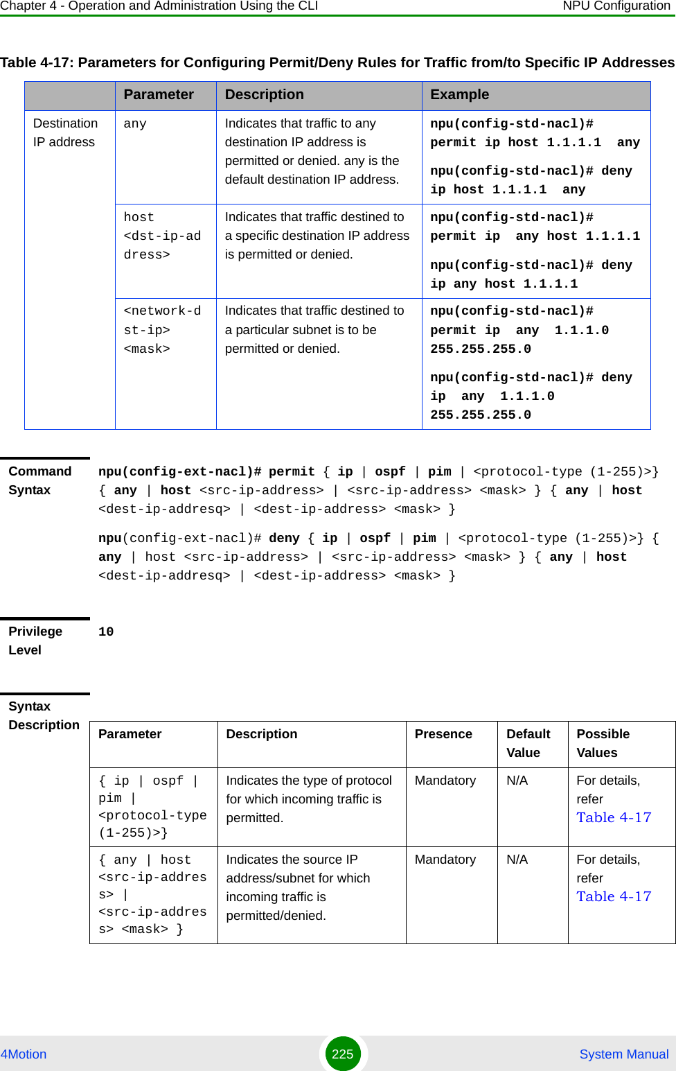
![Chapter 4 - Operation and Administration Using the CLI NPU Configuration4Motion 227 System Manual4.3.9.1.3.2 Configuring Permit/Deny Rules for TCP/UDP TrafficAfter you have created an ACL, you can configure Permit/Deny rules for TCP and UDP traffic from/to specific source and destination IP address and port. This section describes the commands to be used for:“Creating a Permit/Deny Rule for TCP/UDP Traffic (Extended Mode)” on page 227“Deleting a Permit/Deny Rule for TCP/UDP Traffic (Extended Mode)” on page 2334.3.9.1.3.2.1Creating a Permit/Deny Rule for TCP/UDP Traffic (Extended Mode)Run the following commands to specify the Permit rule for TCP/UDP traffic from/to a specific source/destination IP address/port:npu(config-ext-nacl)# permit tcp {any | host <src-ip-address> | <src-ip-address> <src-mask>} [{gt <port-number (1-65535)> | lt <port-number (1-65535)> |eq <port-number (1-65535)> | range <port-number (1-65535)> <port-number (1-65535)>}] {any | host <dest-ip-address> | <dest-ip-address> <dest-mask>} {gt <port-number (1-65535)> | lt <port-number (1-65535)> | eq <port-number (1-65535)> | range <port-number (1-65535)> <port-number (1-65535)>}]{ any | host <src-ip-address> | <src-ip-address> <mask> }Indicates the source IP address/subnet for which the Permit/Deny rule is to be deleted.Mandatory N/A For details, refer Table 4-17{ any | host <dest-ip-addresq> | <dest-ip-address> <mask> }Indicates the destination IP address/subnet for which the Permit/Deny rule is to be deleted.Optional any For details, refer Table 4-17Command ModesExtended ACL configuration modeIMPORTANTYou cannot configure Permit or Deny rules for an ACL that is associated with a Qos marking rule. You can either associate QoS marking rules or permit/deny rules with an ACL.](https://usermanual.wiki/Alvarion-Technologies/BMAX-OR-25.Manual-2/User-Guide-1114030-Page-131.png)
![Chapter 4 - Operation and Administration Using the CLI NPU Configuration4Motion 228 System Manualnpu(config-ext-nacl)# permit udp {any | host <src-ip-address> | <src-ip-address> <src-mask>} [{gt <port-number (1-65535)> | lt <port-number (1-65535)> |eq <port-number (1-65535)> | range <port-number (1-65535)> <port-number (1-65535)>}] {any | host <dest-ip-address> | <dest-ip-address> <dest-mask>} {gt <port-number (1-65535)> | lt <port-number (1-65535)> | eq <port-number (1-65535)> | range <port-number (1-65535)> <port-number (1-65535)>}]Run the following commands to specify the Deny rule for TCP/UDP traffic from/to a specific source/destination IP address/port:npu(config-ext-nacl)# deny tcp {any | host <src-ip-address> | <src-ip-address> <src-mask>} [{gt <port-number (1-65535)> | lt <port-number (1-65535)> |eq <port-number (1-65535)> | range <port-number (1-65535)> <port-number (1-65535)>}] {any | host <dest-ip-address> | <dest-ip-address> <dest-mask>} {gt <port-number (1-65535)> | lt <port-number (1-65535)> | eq <port-number (1-65535)> | range <port-number (1-65535)> <port-number (1-65535)>}]npu(config-ext-nacl)# deny udp {any | host <src-ip-address> | <src-ip-address> <src-mask>} [{gt <port-number (1-65535)> | lt <port-number (1-65535)> |eq <port-number (1-65535)> | range <port-number (1-65535)> <port-number (1-65535)>}] {any | host <dest-ip-address> | <dest-ip-address> <dest-mask>} {gt <port-number (1-65535)> | lt <port-number (1-65535)> | eq <port-number (1-65535)> | range <port-number (1-65535)> <port-number (1-65535)>}]In the above commands, it is mandatory to specify the source and destination IP address for which the Permit/Deny rule is to be created.The following table lists the parameters and their descriptions in these commands:IMPORTANTTo increase the granularity of the Permit/Deny rule you are creating, specify the source and destination port numbers for the source and destination IP addresses.](https://usermanual.wiki/Alvarion-Technologies/BMAX-OR-25.Manual-2/User-Guide-1114030-Page-132.png)
![Chapter 4 - Operation and Administration Using the CLI NPU Configuration4Motion 229 System ManualTable 4-18: Parameters for Configuring Permit/Deny Rules for TCP/UDP TrafficParameter Description ExampleSource IP addressany Indicates that incoming TCP/UDP traffic from any source IP address is permitted or denied.npu(config-ext-nacl)# permit tcp any anynpu(config-ext-nacl)# deny udp any host <src-ip-address>Indicates that incoming TCP/UDP traffic from a specific source IP address is permitted or denied.npu(config-ext-nacl)# permit tcp host 1.1.1.1 anynpu(config-ext-nacl)# deny udp host 1.1.1.1 <network-src-ip> <mask>Indicates that incoming TCP/UDP traffic is to be permitted or denied for a particular subnet.npu(config-ext-nacl)# permit tcp 1.1.1.0 255.255.255.0 anynpu(config-ext-nacl)# deny udp 1.1.1.0 255.255.255.0 Source port [{gt <port-number (1-65535)> Indicates that incoming TCP/ UDP traffic is to be permitted or denied from the source port for which the port number is greater than the value of this parameter.npu(config-ext-nacl)# permit tcp 1.1.1.0 255.255.255.0 gt 1111npu(config-ext-nacl)# deny udp host 1.1.1.1 gt 1010 [{lt <port-number (1-65535)> Indicates that incoming TCP/ UDP traffic is to be permitted or denied from the source port for which the port number is less than the value of this parameter.npu(config-ext-nacl)# permit tcp 1.1.1.0 255.255.255.0 lt 1111npu(config-ext-nacl)# deny udp host 1.1.1.1 lt 1010[{eq <port-number (1-65535)> Indicates that incoming TCP/ UDP traffic is to be permitted or denied from the source port for which the port number is equal to the value of this parameter.npu(config-ext-nacl)# permit tcp 1.1.1.0 255.255.255.0 eq 8080npu(config-ext-nacl)# deny udp host 1.1.1.1 eq 4040range <port-number (1-65535)> <port-number (1-65535)>}]Indicates that incoming TCP/ UDP traffic is to be permitted or denied from the source port for which the port number is within the range specified by this parameter.npu(config-ext-nacl)# permit tcp 1.1.1.0 255.255.255.0 range 1010 8080npu(config-ext-nacl)# deny udp host 1.1.1.1 range 1010 4040](https://usermanual.wiki/Alvarion-Technologies/BMAX-OR-25.Manual-2/User-Guide-1114030-Page-133.png)
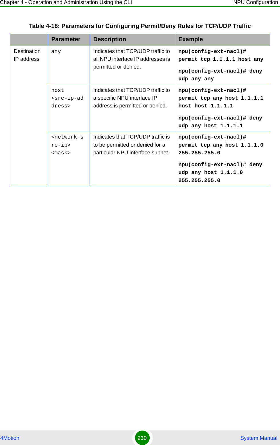
![Chapter 4 - Operation and Administration Using the CLI NPU Configuration4Motion 231 System ManualDestination port[{gt <port-number (1-65535)> Indicates that TCP/ UDPtraffic is to be permitted or denied to the NPU interface source port for which the port number is greater than the value of this parameter.npu(config-ext-nacl)# permit tcp host 1.1.1.1 host any gt 8080npu(config-ext-nacl)# deny udp any any[{lt <port-number (1-65535)> Indicates that TCP/ UDP traffic is to be permitted or denied to the NPU interface source port for which the port number is less than the value of this parameter.npu(config-ext-nacl)# permit tcp host 1.1.1.0 255.255.255.0 any lt 1111npu(config-ext-nacl)# deny udp any host 1.1.1.1 lt 1010[{eq <port-number (1-65535)> Indicates that TCP/ UDP traffic is to be permitted or denied to the NPU interface source port for which the port number is equal to the value of this parameter.npu(config-ext-nacl)# permit tcp any 1.1.1.0 255.255.255.0 eq 8080npu(config-ext-nacl)# deny udp any host 1.1.1.1 eq 4040range <port-number (1-65535)> <port-number (1-65535)>}]Indicates that TCP/ UDP traffic is to be permitted or denied the NPU interface source port for which the port number is within the range specified by this parameter.npu(config-ext-nacl)# permit tcp host 1.1.1.1 host 1.1.1.0 255.255.255.0 range 1010 8080npu(config-ext-nacl)# deny udp host 1.1.1.1 any range 1010 4040Command Syntaxnpu(config-ext-nacl)# deny tcp {any | host <src-ip-address> | <src-ip-address> <src-mask> } [{gt <port-number (1-65535)> | lt <port-number (1-65535)> |eq <port-number (1-65535)> | range <port-number (1-65535)> <port-number (1-65535)>}] {any | host <dest-ip-address> | <dest-ip-address> <dest-mask>} {gt <port-number (1-65535)> | lt <port-number (1-65535)> | eq <port-number (1-65535)> | range <port-number (1-65535)> <port-number (1-65535)>}]npu(config-ext-nacl)# deny udp {any | host <src-ip-address> | <src-ip-address> <src-mask> } [{gt <port-number (1-65535)> | lt <port-number (1-65535)> |eq <port-number (1-65535)> | range <port-number (1-65535)> <port-number (1-65535)>}] {any | host <dest-ip-address> | <dest-ip-address> <dest-mask>} {gt <port-number (1-65535)> | lt <port-number (1-65535)> | eq <port-number (1-65535)> | range <port-number (1-65535)> <port-number (1-65535)>}]Table 4-18: Parameters for Configuring Permit/Deny Rules for TCP/UDP TrafficParameter Description Example](https://usermanual.wiki/Alvarion-Technologies/BMAX-OR-25.Manual-2/User-Guide-1114030-Page-135.png)
![Chapter 4 - Operation and Administration Using the CLI NPU Configuration4Motion 232 System ManualPrivilege Level10Syntax Description Parameter Description Presence Default ValuePossible Valuesany | host <src-ip-address> | <src-ip-address> <src-mask>Indicates the source host for which incoming TCP/UDP traffic is permitted/denied.Mandatory N/A For details, refer Table 4-18[{gt <port-number (1-65535)> | lt <port-number (1-65535)> |eq <port-number (1-65535)> | range <port-number (1-65535)> <port-number (1-65535)>}]Indicates the source port from which incoming TCP/UDP traffic is permitted/denied.Optional 0-65535 For details, refer Table 4-18any | host <dest-ip-address> | <dest-ip-address> <dest-mask>Indicates the destination IP address/subnet for which TCP/UDP traffic is permitted/denied.Mandatory N/A For details, refer Table 4-18](https://usermanual.wiki/Alvarion-Technologies/BMAX-OR-25.Manual-2/User-Guide-1114030-Page-136.png)
![Chapter 4 - Operation and Administration Using the CLI NPU Configuration4Motion 233 System Manual4.3.9.1.3.2.2Deleting a Permit/Deny Rule for TCP/UDP Traffic (Extended Mode)Run the following commands to delete a Permit rule for TCP/UDP traffic from/to a specific IP address/port:npu(config-ext-nacl)# no permit tcp {any | host <src-ip-address> | <src-ip-address> <src-mask>} [{gt <port-number (1-65535)> | lt <port-number (1-65535)> |eq <port-number (1-65535)> | range <port-number (1-65535)> <port-number (1-65535)>}] {any | host <dest-ip-address> | <dest-ip-address> <dest-mask>} {gt <port-number (1-65535)> | lt <port-number (1-65535)> | eq <port-number (1-65535)> | range <port-number (1-65535)> <port-number (1-65535)>}]npu(config-ext-nacl)# no permit udp {any | host <src-ip-address> | <src-ip-address> <src-mask>} [{gt <port-number (1-65535)> | lt <port-number (1-65535)> |eq <port-number (1-65535)> | range <port-number (1-65535)> <port-number (1-65535)>}] {any | host <dest-ip-address> | <dest-ip-address> <dest-mask>} {gt <port-number (1-65535)> | lt <port-number (1-65535)> | eq <port-number (1-65535)> | range <port-number (1-65535)> <port-number (1-65535)>}]Run the following commands to delete a Deny rule for TCP/UDP traffic from/to a specific IP address/port:{gt <port-number (1-65535)> | lt <port-number (1-65535)> | eq <port-number (1-65535)> | range <port-number (1-65535)> <port-number (1-65535)>}]Indicates the destination port to which TCP/UDP traffic is permitted/denied.Optional 0-65535 For details, refer Table 4-18Command ModesExtended ACL configuration mode](https://usermanual.wiki/Alvarion-Technologies/BMAX-OR-25.Manual-2/User-Guide-1114030-Page-137.png)
![Chapter 4 - Operation and Administration Using the CLI NPU Configuration4Motion 234 System Manualnpu(config-ext-nacl)# no deny tcp {any | host <src-ip-address> | <src-ip-address> <src-mask>} [{gt <port-number (1-65535)> | lt <port-number (1-65535)> |eq <port-number (1-65535)> | range <port-number (1-65535)> <port-number (1-65535)>}] {any | host <dest-ip-address> | <dest-ip-address> <dest-mask>} {gt <port-number (1-65535)> | lt <port-number (1-65535)> | eq <port-number (1-65535)> | range <port-number (1-65535)> <port-number (1-65535)>}]npu(config-ext-nacl)# no deny udp {any | host <src-ip-address> | <src-ip-address> <src-mask>} [{gt <port-number (1-65535)> | lt <port-number (1-65535)> |eq <port-number (1-65535)> | range <port-number (1-65535)> <port-number (1-65535)>}] {any | host <dest-ip-address> | <dest-ip-address> <dest-mask>} {gt <port-number (1-65535)> | lt <port-number (1-65535)> | eq <port-number (1-65535)> | range <port-number (1-65535)> <port-number (1-65535)>}]Command Syntax (for Permit Rule)npu(config-ext-nacl)# no permit tcp {any | host <src-ip-address> | <src-ip-address> <src-mask> } [{gt <port-number (1-65535)> | lt <port-number (1-65535)> |eq <port-number (1-65535)> | range <port-number (1-65535)> <port-number (1-65535)>}] {any | host <dest-ip-address> | <dest-ip-address> <dest-mask>} {gt <port-number (1-65535)> | lt <port-number (1-65535)> | eq <port-number (1-65535)> | range <port-number (1-65535)> <port-number (1-65535)>}]npu(config-ext-nacl)# no permit udp {any | host <src-ip-address> | <src-ip-address> <src-mask> } [{gt <port-number (1-65535)> | lt <port-number (1-65535)> |eq <port-number (1-65535)> | range <port-number (1-65535)> <port-number (1-65535)>}] {any | host <dest-ip-address> | <dest-ip-address> <dest-mask>} {gt <port-number (1-65535)> | lt <port-number (1-65535)> | eq <port-number (1-65535)> | range <port-number (1-65535)> <port-number (1-65535)>}]](https://usermanual.wiki/Alvarion-Technologies/BMAX-OR-25.Manual-2/User-Guide-1114030-Page-138.png)
![Chapter 4 - Operation and Administration Using the CLI NPU Configuration4Motion 235 System ManualCommand Syntax (for Deny Rule)npu(config-ext-nacl)# no deny tcp {any | host <src-ip-address> | <src-ip-address> <src-mask> } [{gt <port-number (1-65535)> | lt <port-number (1-65535)> |eq <port-number (1-65535)> | range <port-number (1-65535)> <port-number (1-65535)>}] {any | host <dest-ip-address> | <dest-ip-address> <dest-mask>} {gt <port-number (1-65535)> | lt <port-number (1-65535)> | eq <port-number (1-65535)> | range <port-number (1-65535)> <deny-number (1-65535)>}]npu(config-ext-nacl)# no deny udp {any | host <src-ip-address> | <src-ip-address> <src-mask> } [{gt <port-number (1-65535)> | lt <port-number (1-65535)> |eq <port-number (1-65535)> | range <port-number (1-65535)> <port-number (1-65535)>}] {any | host <dest-ip-address> | <dest-ip-address> <dest-mask>} {gt <port-number (1-65535)> | lt <port-number (1-65535)> | eq <port-number (1-65535)> | range <port-number (1-65535)> <port-number (1-65535)>}]Privilege Level10Syntax Description Parameter Description Presence Default ValuePossible Valuesany | host <src-ip-address> | <src-ip-address> <src-mask>Indicates the source host for which the Permit/Deny rule for incoming TCP/UDP traffic is to be deleted.Mandatory N/A For details, refer Table 4-18[{gt <port-number (1-65535)> | lt <port-number (1-65535)> |eq <port-number (1-65535)> | range <port-number (1-65535)> <port-number (1-65535)>}]Indicates the source port for which the Permit/Deny rule for incoming TCP/UDP traffic is to be deleted.Optional 1-65535 For details, refer Table 4-18](https://usermanual.wiki/Alvarion-Technologies/BMAX-OR-25.Manual-2/User-Guide-1114030-Page-139.png)
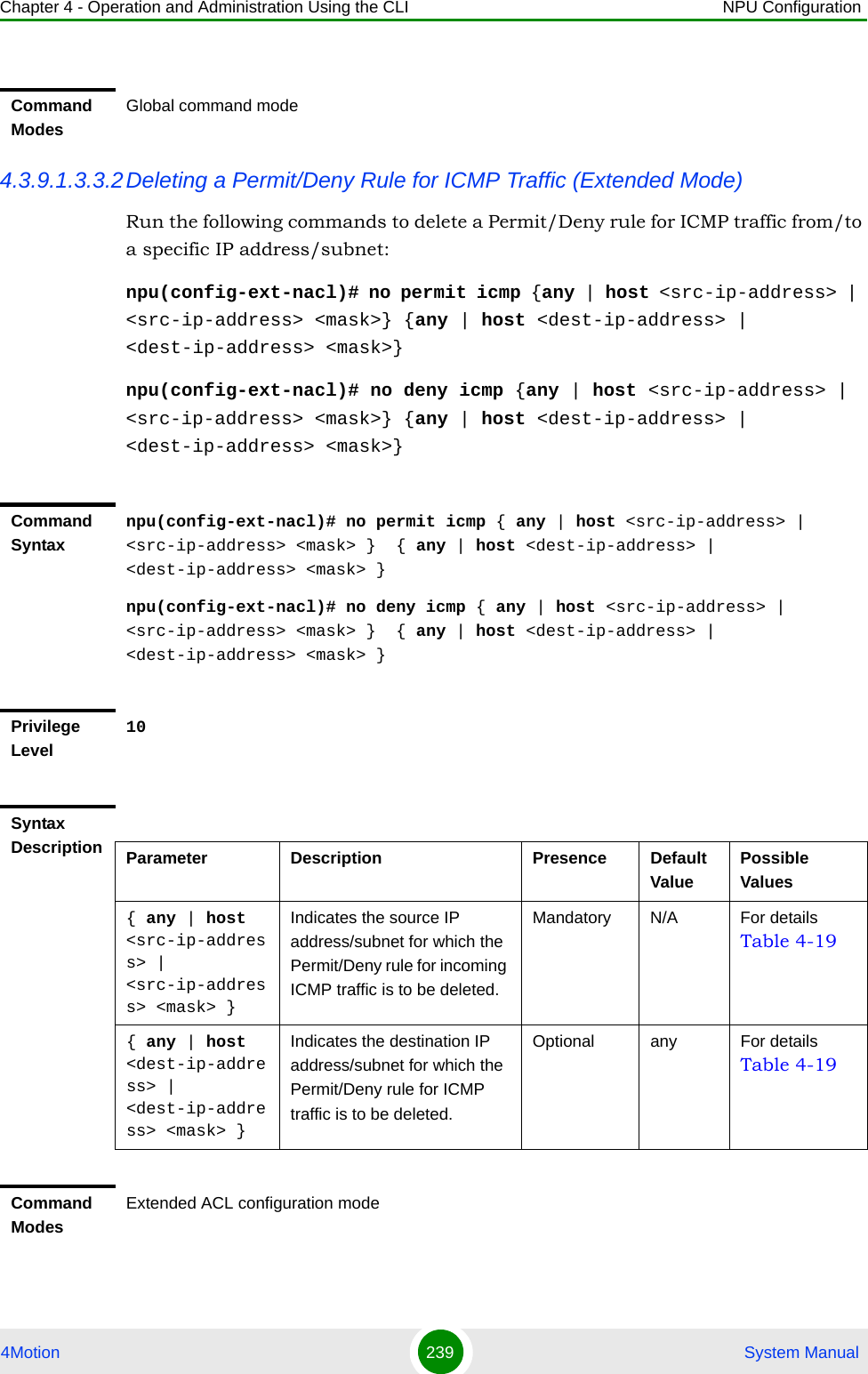
![Chapter 4 - Operation and Administration Using the CLI NPU Configuration4Motion 236 System Manual4.3.9.1.3.3 Configuring Permit/Deny Rules for ICMP TrafficAfter you have created an ACL, you can configure Permit/Deny rules for ICMP traffic from/to specific a source and destination IP address/subnet. This section describes the commands to be used for:“Creating a Permit/Deny Rule for ICMP Traffic (Extended Mode)” on page 236“Deleting a Permit/Deny Rule for ICMP Traffic (Extended Mode)” on page 2394.3.9.1.3.3.1Creating a Permit/Deny Rule for ICMP Traffic (Extended Mode)Run the following commands to specify the Permit/Deny rule for ICMP traffic from/to a specific source/destination IP address/subnet:any | host <dest-ip-address> | <dest-ip-address> <dest-mask>Indicates the NPU IP address/subnet for which the Permit/Deny rule for TCP/UDP traffic is to be deleted.Mandatory N/A For details, refer Table 4-18[{gt <port-number (1-65535)> | lt <port-number (1-65535)> |eq <port-number (1-65535)> | range <port-number (1-65535)> <port-number (1-65535)>}]Indicates the NPU interface port for which the Permit/Deny rule for incoming TCP/UDP traffic is to be deleted.Optional 1-65535 For details, refer Table 4-18Command ModesExtended ACL configuration modeIMPORTANTYou cannot configure Permit or Deny rules for an ACL that is associated with a Qos marking rule. You can either associate QoS marking rules or permit/deny rules with an ACL.](https://usermanual.wiki/Alvarion-Technologies/BMAX-OR-25.Manual-2/User-Guide-1114030-Page-140.png)

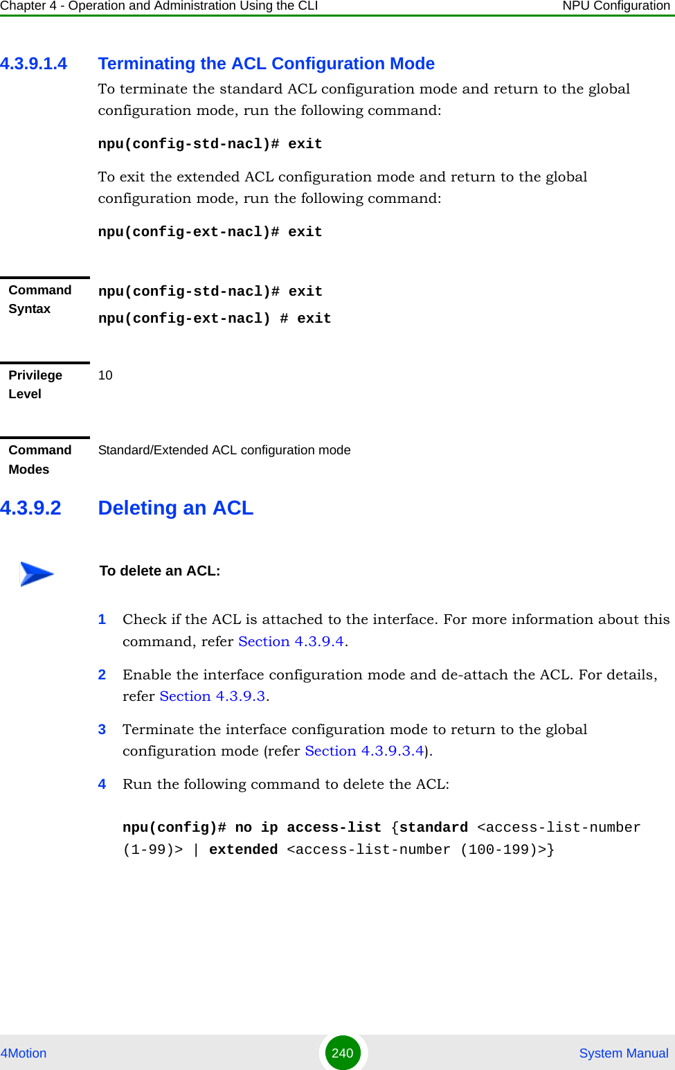
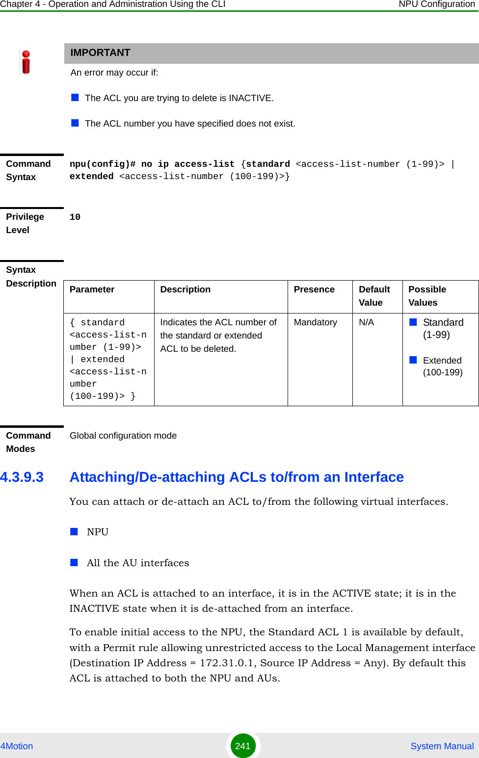
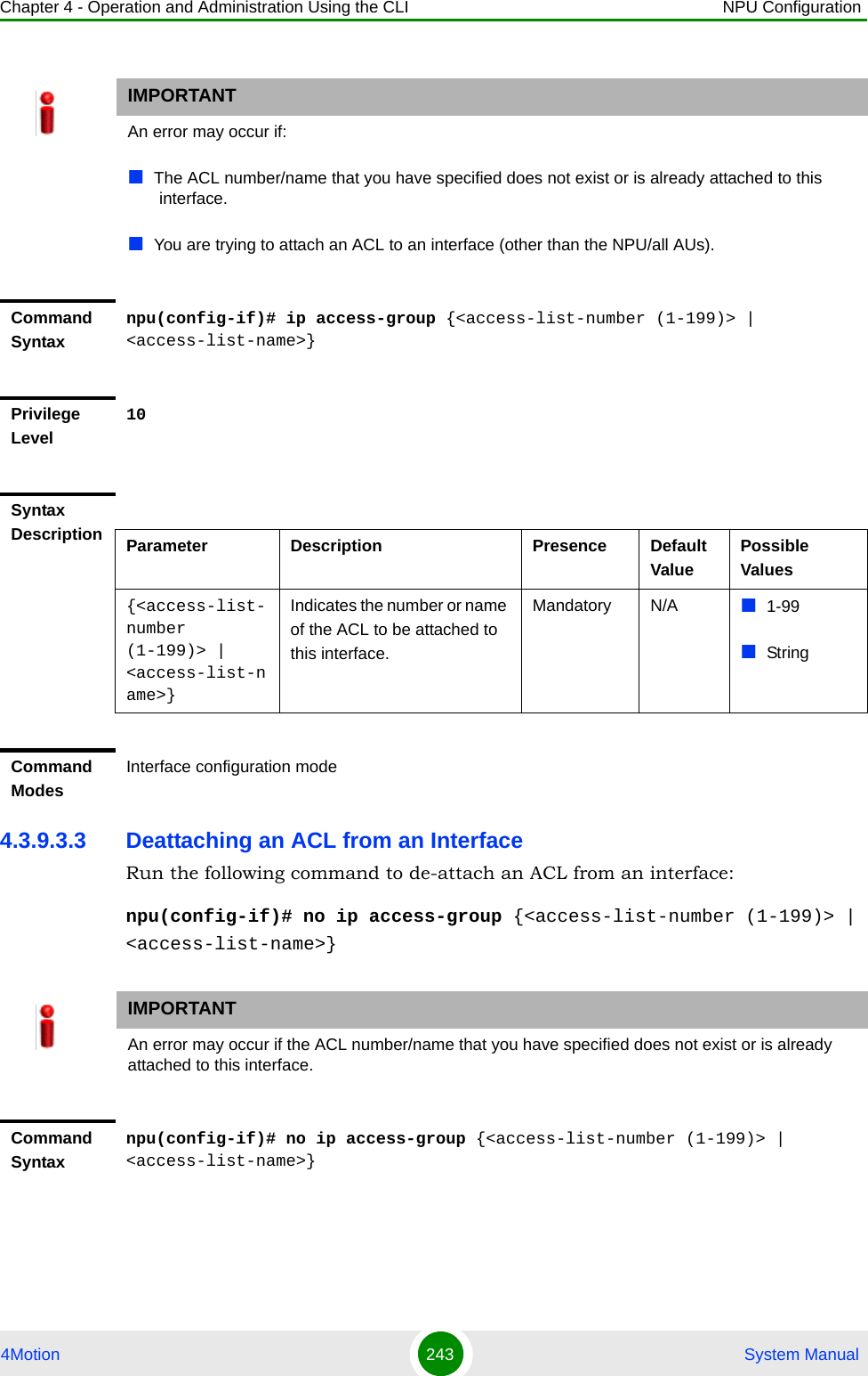
![Chapter 4 - Operation and Administration Using the CLI NPU Configuration4Motion 244 System Manual4.3.9.3.4 Terminating the Interface Configuration ModeTo exit the interface configuration mode and return to the global configuration mode, run the following command:npu(config-if)# exit4.3.9.4 Displaying ACL Configuration InformationRun the following command to display the configuration information for a specific ACL:npu# show access-lists [{<access-list-number (1-199)> | <access-list-name}]Privilege Level10Syntax Description Parameter Description Presence Default ValuePossible Values{<access-list-number (1-199)> | <access-list-name>}Indicates the number/name of the ACL to be deattached from this interface.Mandatory N/A 1-99StringCommand ModesInterface configuration modeCommand Syntaxnpu(config-if)# exitPrivilege Level10Command ModesInterface configuration modeIMPORTANTAn error may occur if the ACL number/name you have specified does not exist.](https://usermanual.wiki/Alvarion-Technologies/BMAX-OR-25.Manual-2/User-Guide-1114030-Page-148.png)
![Chapter 4 - Operation and Administration Using the CLI NPU Configuration4Motion 245 System ManualCommand Syntaxnpu# show access-lists [{<access-list-number (1-199)> | <access-list-name}]Privilege Level1Syntax Description Parameter Description Presence Default ValuePossible Values[{<access-list-number (1-199)> | <access-list-name}]Indicates the number or name of the ACL for which configuration information is to be displayed. If you do not provide the ACL number or name, configuration information is displayed for all ACLs.Optional N/A 1-199StringDisplay Format (Standard)Standard IP Access List <ACL number>---------------------------------------------------------------------Access List Name(Alias) :<ACL Name> Interface List : <Interface Name>, <Interface Name> Status : <value> Source IP address : <value> Source IP address mask : <value> Destination IP address : <value>Destination IP address mask : <value> Rule Action : <value> Packet Match Count : <value> Rule Row Status : <value>](https://usermanual.wiki/Alvarion-Technologies/BMAX-OR-25.Manual-2/User-Guide-1114030-Page-149.png)
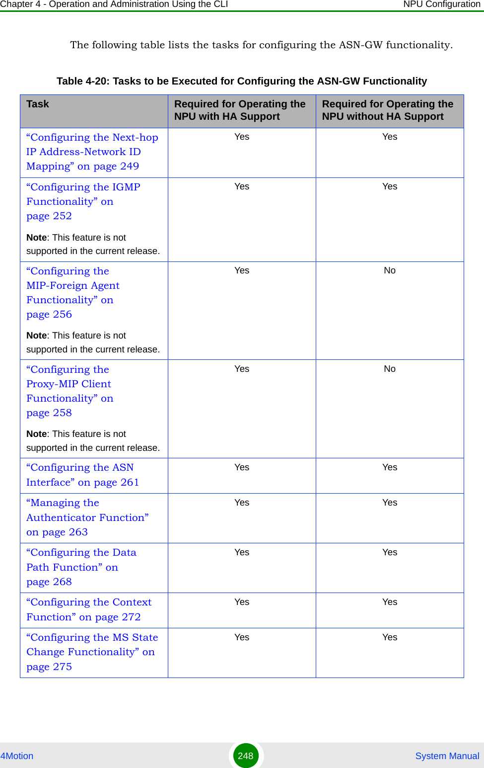
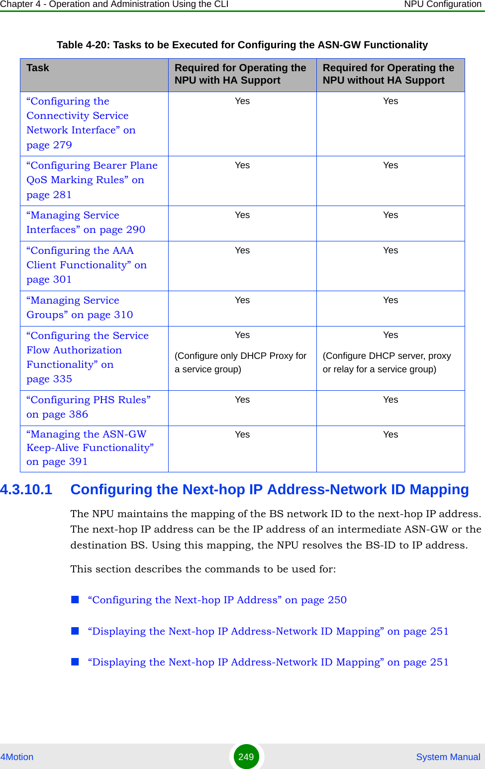
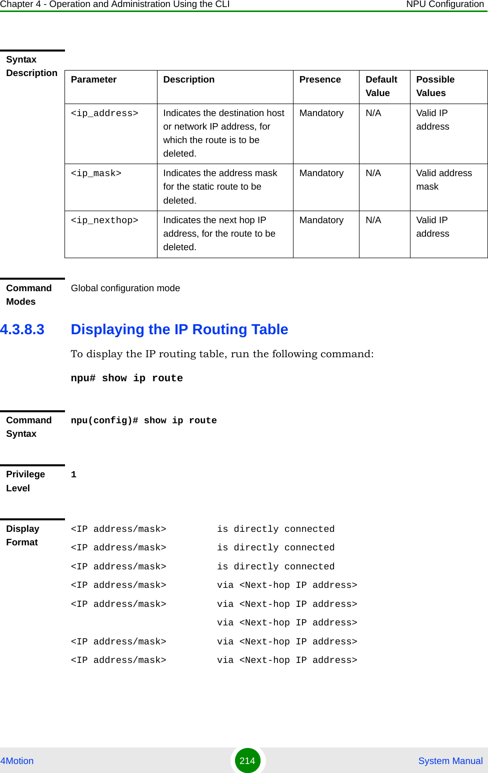
![Chapter 4 - Operation and Administration Using the CLI NPU Configuration4Motion 250 System Manual4.3.10.1.1 Configuring the Next-hop IP AddressTo map the next-hop IP address for a specific network ID, run the following command:npu(config)# idip <nw-id> <next-hop-ipaddr>For example, run the following command to map the MAC address of the BS with the next-hop IP address:npu(config)# idip 112233445566 10.0.0.14.3.10.1.2 Deleting Next-hop IP Address-Network ID MappingsTo delete a specific or all next-hop IP address-network ID mappings, run the following command:npu(config)# no idip [<nw-id>]NOTERefer to Section 4.3.10.2.1 for a list of existing next-hop IP address-network ID mappings.Command Syntaxnpu(config)# idip <nw-id> <next-hop-ipaddr>Privilege Level10Syntax Description Parameter Description Presence Default ValuePossible Values<nw-id> Denotes the BS ID. This parameter is a MAC address, and should be specified without colons.Mandatory N/A 6-byte ID<next-hop-ipaddr>Denotes the next hop IP address for a particular BS.Mandatory N/A Valid IP AddressCommand ModesGlobal configuration mode](https://usermanual.wiki/Alvarion-Technologies/BMAX-OR-25.Manual-2/User-Guide-1114030-Page-154.png)
![Chapter 4 - Operation and Administration Using the CLI NPU Configuration4Motion 251 System Manual4.3.10.1.3 Displaying the Next-hop IP Address-Network ID MappingTo display the next-hop-IP address mapped to a network ID or all network IDs, run the following command:npu# show idip [<nw-id>]Specify the network ID if you want to display a particular the next-hop-IP address-network ID mapping. Do not specify a value for this parameter if you want to view all the next-hop-IP address-network ID mappings.CAUTIONSpecify the network ID if you want to delete a specific next-hop IP address-network ID mapping. Otherwise all the configured mappings are deleted.Command Syntaxnpu(config)# no idip [<nw-id>]Privilege Level10Syntax Description Parameter Description Presence Default ValuePossible Values<nw-id> Denotes the network ID(s) for which an IDIP context is to be removed.Specify this parameter only if you want to delete a specific network ID. If you do not specify a value for this parameter, all configured network IDs are deleted.Mandatory N/A 6-byte IDCommand ModesGlobal configuration modeCommand Syntaxnpu# show idip [<nw-id>]](https://usermanual.wiki/Alvarion-Technologies/BMAX-OR-25.Manual-2/User-Guide-1114030-Page-155.png)
![Chapter 4 - Operation and Administration Using the CLI NPU Configuration4Motion 252 System Manual4.3.10.2 Configuring the IGMP FunctionalityThe NPU serves as the IGMP proxy server between a group of MSs and the multicast router. In addition, it serves as a router for all MSs that are connected to it. It receives periodic IGMP reports for all MSs that are members of a multicast group. Based on these reports, the NPU maintains a database of members. Each time there is a change in the membership database, because of a member leaving or joining the group, the NPU sends a report to the multicast router. The NPU also Privilege Level1Syntax Description Parameter Description Presence Default ValuePossible Values[<nw-id>] Denotes the network ID (s) for which you want to view the next-hop IP addresses already mapped to it. Specify a value for this parameter if you want to view the next-hop IP address(es) defined for a specific network ID. If you do not specify any value for this parameter, all the existing entries for mappings of network IDs- next-hop IP addresses are displayed.Optional N/A 6-byte IDDisplay Formatnw-id next-hop-ip address<Network ID 1> <Ip Address><Network ID 2> <Ip Address>Command ModesGlobal command modeIMPORTANTThe IGMP functionality is not supported in the current release.](https://usermanual.wiki/Alvarion-Technologies/BMAX-OR-25.Manual-2/User-Guide-1114030-Page-156.png)
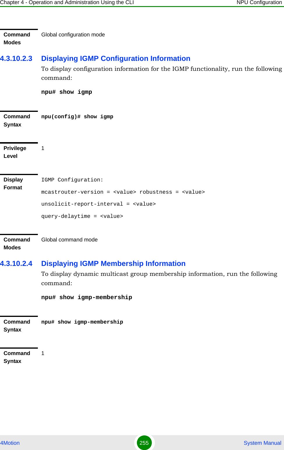
![Chapter 4 - Operation and Administration Using the CLI NPU Configuration4Motion 253 System Manualserves as a host for the multicast router and sends membership reports in response to membership queries.This section describes the commands to be used for: “Configuring IGMP Parameters” on page 253“Restoring the Default Configuration Parameters for the IGMP Functionality” on page 254“Displaying IGMP Configuration Information” on page 255“Displaying IGMP Membership Information” on page 2554.3.10.2.1 Configuring IGMP ParametersTo configure the IGMP functionality, run the following command:npu(config)# igmp [mcastrouter-version <version>] [robustness <retransmissions>] [unsolicit-report-interval <timeout>] [query-delaytime <timeout>]NOTEYou can display configuration information for the IGMP functionality. For details, refer to Section 4.3.10.2.3.IMPORTANTAn error may occur if you provide an invalid value for any of these parameters. Refer the syntax description for more information about the appropriate values and format for configuring these parameters.Command Syntaxnpu(config)# igmp [mcastrouter-version <version>] [robustness <retransmissions>] [unsolicit-report-interval <timeout>] [query-delaytime <timeout>]Privilege Level15](https://usermanual.wiki/Alvarion-Technologies/BMAX-OR-25.Manual-2/User-Guide-1114030-Page-157.png)
![Chapter 4 - Operation and Administration Using the CLI NPU Configuration4Motion 254 System Manual4.3.10.2.2 Restoring the Default Configuration Parameters for the IGMP FunctionalityTo restore the default configuration for the IGMP functionality, run the following command:npu(config)# no igmp [mcastrouter-version] [robustness] [unsolicit-report-interval] [query-delaytime]Syntax Description Parameter Description Presence Default ValuePossible Values[mcastrouter-version <version>]Denotes the IGMP version of the multicast router.Optional IGMPv3 IGMPv2IGMPv3[robustness <retransmissions>]Determines the number of retransmissions of the IGMP reports sent by the NPU. Optional 2 1 - 2^8[unsolicit-report-interval <timeout>]Denotes the interval, in seconds, between successive retransmissions of unsolicited IGMP reports sent by the NPU.Optional 1 1 - 100[query-delaytime <timeout>]Denotes the interval, in seconds, between general queries sent by the multicast router. Optional 125 1 - 200Command ModesGlobal configuration modeNOTERefer to Section 4.3.10.2.1 for a description and default values of these parameters. Command Syntaxnpu(config)# no igmp [mcastrouter-version] [robustness] [unsolicit-report-interval] [query-delaytime]Privilege Level15](https://usermanual.wiki/Alvarion-Technologies/BMAX-OR-25.Manual-2/User-Guide-1114030-Page-158.png)
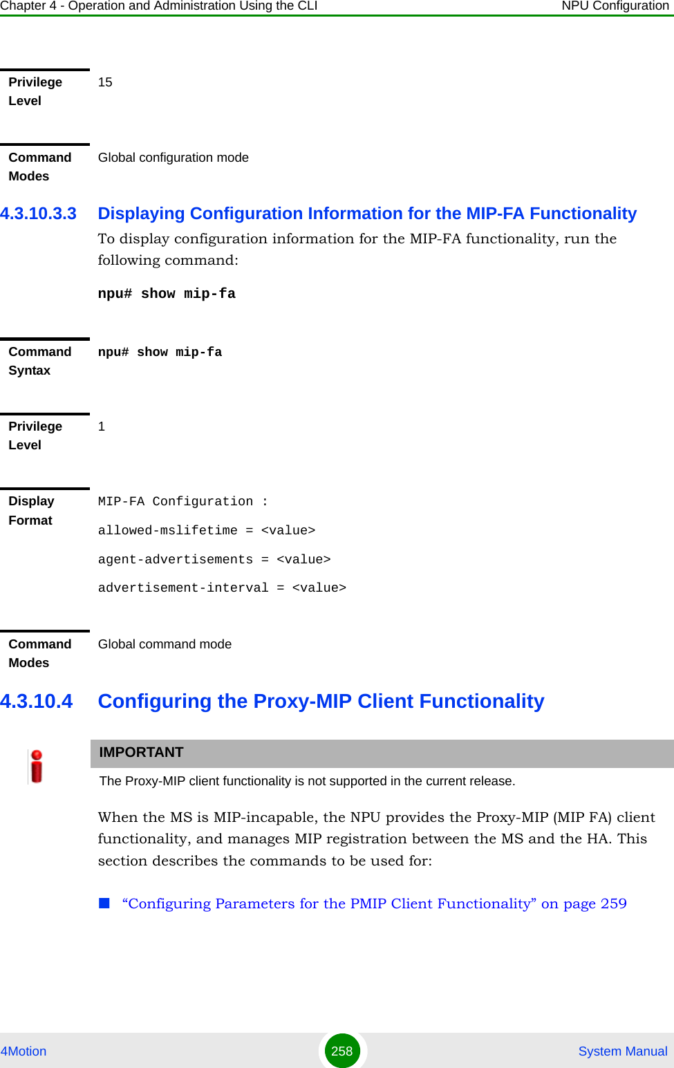
![Chapter 4 - Operation and Administration Using the CLI NPU Configuration4Motion 256 System Manual4.3.10.3 Configuring the MIP-Foreign Agent FunctionalityWhen the MS is MIP-enabled, the NPU serves as the Foreign Agent (FA) for transferring mobile IP messages between the MS and the HA. As the FA, the NPU is responsible for registering the MS in the network. It provides security by using the security associations (MIP keys) between the MS and FA, and FA and HA. This section describes the commands to be used for: “Configuring Parameters for the MIP-FA Functionality” on page 256“Restoring the Default Configuration Parameters for the MIP-FA Functionality” on page 257“Displaying Configuration Information for the MIP-FA Functionality” on page 2584.3.10.3.1 Configuring Parameters for the MIP-FA FunctionalityTo configure MIP-FA parameters, run the following command:npu(config)# mip-fa [allowed-mslifetime <timeout>] [agent-advertisements <no of agent advertisement>] [advertisement-interval <timeout>]Display FormatIGMP Membership :GrpMulticast-addr Src-addrlist<value> <value> <value> ….Command ModesGlobal configuration modeIMPORTANTThe MIP-Foreign Agent functionality is not supported in the current release.NOTEYou can display configuration information for the MIP-FA functionality. For details, refer to Section 4.3.10.3.3.](https://usermanual.wiki/Alvarion-Technologies/BMAX-OR-25.Manual-2/User-Guide-1114030-Page-160.png)
![Chapter 4 - Operation and Administration Using the CLI NPU Configuration4Motion 257 System Manual4.3.10.3.2 Restoring the Default Configuration Parameters for the MIP-FA FunctionalityTo restore the default configuration for the MIP-FA functionality, run the following command:npu(config)# no mip-fa [allowed-mslifetime] [agent-advertisements] [advertisement-interval]Command Syntaxnpu(config)# mip-fa [allowed-mslifetime <timeout>] [agent-advertisements <no of agent advertisement>] [advertisement-interval <timeout>]Privilege Level15Syntax Description Parameter Description Presence Default ValuePossible Values[allowed-mslifetime <timeout>]Denotes the maximum period, in seconds, for which the IP address allocated to the MS is active.Optional 9000 0-9000[agent-advertisements <no of agent advertisement>]Denotes the maximum number of initial agent advertisements sent to the MS.Optional 3 0-5[advertisement-interval <timeout>]Denotes the interval, in seconds, between successive agent advertisements.Optional 10 5-100Command ModesGlobal configuration modeNOTERefer to Section 4.3.10.3.1 for a description and default values of these parameters. Command Syntaxnpu(config)# no mip-fa [allowed-mslifetime] [agent-advertisements] [advertisement-interval]](https://usermanual.wiki/Alvarion-Technologies/BMAX-OR-25.Manual-2/User-Guide-1114030-Page-161.png)
![Chapter 4 - Operation and Administration Using the CLI NPU Configuration4Motion 259 System Manual“Restoring the Default Configuration Parameters for the PMIP Client Functionality” on page 260“Displaying Configuration Information for the PMIP Client Functionality” on page 2614.3.10.4.1 Configuring Parameters for the PMIP Client FunctionalityRun the following command to configure the PMIP client functionality to specify how registration of a MIP-incapable MS should be managed:npu(config)# mip-client [mslifetime <timeout>] [mslifetime-guard <percent>] [registration-retries <retransmissions>] [registration-interval <timeout>]NOTEYou can display configuration information for the PMIP client functionality. For details, refer to Section 4.3.10.4.3.IMPORTANTAn error may occur if you provide an invalid for any of these parameters. Refer the syntax description for more information about the appropriate values and format for configuring these parameters.Command Syntaxnpu(config)# mip-client [mslifetime <timeout>] [mslifetime-guard <percent>] [registration-retries <retransmissions>] [registration-interval <timeout>]Privilege Level15Syntax Description Parameter Description Presence Default ValuePossible Values[mslifetime <timeout>]Denotes the maximum period, in seconds, for which the HA will maintain the MIP binding. This information is sent in the MIP registration message. At the end of this period, the NPU de-registers the MS.Optional 9000 0-9000](https://usermanual.wiki/Alvarion-Technologies/BMAX-OR-25.Manual-2/User-Guide-1114030-Page-163.png)
![Chapter 4 - Operation and Administration Using the CLI NPU Configuration4Motion 260 System Manual4.3.10.4.2 Restoring the Default Configuration Parameters for the PMIP Client FunctionalityTo restore the default configuration for the PMIP client functionality, run the following command:npu(config)# no mip-client [mslifetime] [mslifetime-guard] [registration-retries] [registration-interval][mslifetime-guard <percent>]Denotes the period for which the PMIP remains active. The value of this parameter should be a percentage of the mslifetime parameter. At the end of this period, the PMIP attempts re-registration.Optional 65% 0-100[registration-retries <retransmissions>] Denotes the maximum number of registration requests that can be sent by the NPU.Optional 3 0-5[registration-interval <timeout>]Denotes the interval between successive requests of an MS, in seconds, within which the MIP registration response should be sent by the HA.Optional 10 5-100Command ModesGlobal configuration modeNOTERefer to Section 4.3.10.4.1 for a description and default values of these parameters. Command Syntaxnpu(config)# no mip-client [mslifetime] [mslifetime-guard] [registration-retries] [registration-interval]Privilege Level15Command ModesGlobal configuration mode](https://usermanual.wiki/Alvarion-Technologies/BMAX-OR-25.Manual-2/User-Guide-1114030-Page-164.png)
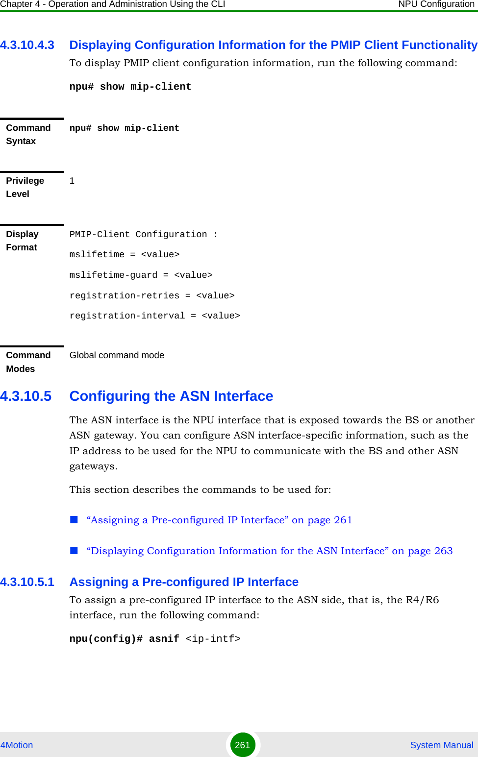
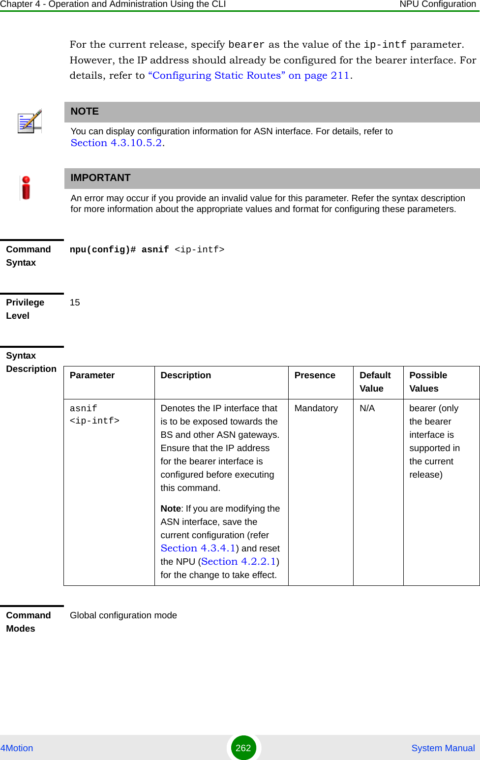
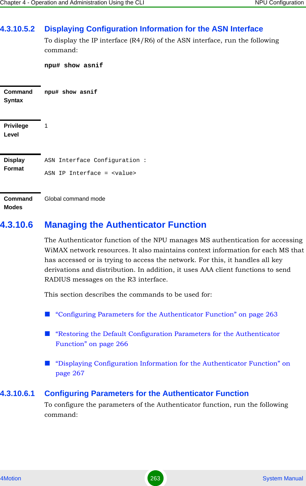
![Chapter 4 - Operation and Administration Using the CLI NPU Configuration4Motion 264 System Manualnpu(config)# authenticator [eapidreq-retries <retransmissions>] [eapidreq-interval <timeout>] [ntwentry-holdtime <timeout>] [eaptransfer-retries <retransmissions>] [eaptransfer-interval <timeout>] [reauth-attempts <counter>] [reauthcmplt-holdtime <timeout>] [eaptransfer-roundtrips <counter>] [pmk-lifetime <timeout>] [pmk-guardtime <timeout>] [authfailure-holdtime <timeout>] [max-ntwentry <counter>]NOTEYou can display configuration information for the Authenticator function. For details, refer to Section 4.3.10.6.3IMPORTANTAn error may occur if you provide an invalid value for any of these parameters. Refer the syntax description for more information about the appropriate values and format for configuring these parameters.Command Syntaxnpu(config)# authenticator [eapidreq-retries <retransmissions>] [eapidreq-interval <timeout>] [ntwentry-holdtime <timeout>] [eaptransfer-retries <retransmissions>] [eaptransfer-interval <timeout>] [reauth-attempts <counter>] [reauthcmplt-holdtime <timeout>] [eaptransfer-roundtrips <counter>] [pmk-lifetime <timeout>] [pmk-guardtime <timeout>] [authfailure-holdtime <timeout>] [max-ntwentry <counter>]Privilege Level15Syntax Description Parameter Description Presence Default ValuePossible Values[eapidreq-retries <retransmissions>]Denotes the number of times the NPU can retransmit the EAP ID request until it receives a EAP ID response.Optional 3 0-5[eapidreq-interval <timeout>]Denotes the period, in milliseconds, for which the NPU should wait for the response to the request for the EAP ID.Optional 500 10-100000](https://usermanual.wiki/Alvarion-Technologies/BMAX-OR-25.Manual-2/User-Guide-1114030-Page-168.png)
![Chapter 4 - Operation and Administration Using the CLI NPU Configuration4Motion 265 System Manual[ntwentry-holdtime <timeout>] Denotes the period, in seconds, within which the MS should be authenticated for initial entry into the network. If the MS is not authenticated within this period, the NPU terminates the request for network entry.Optional 5 0-100[eaptransfer-retries <retransmissions>] Denotes the maximum number of times the MS can attempt for initial entry to the network. If the number of EAP transfers exceeds the value of this parameter, the NPU de-registers the MS.Optional 3 0-5[eaptransfer-interval <timeout>] Denotes the period, in milliseconds, the NPU waits for the EAP identity response.Optional 500 10 - 100000[reauth-attempts <counter>] Denotes the maximum number of times the NPU may handle a an MS/network-initiated re-authentication request. When the number of re-authentication attempts exceeds the value of this parameter, the MS is de-registered.Optional 3 0-10[reauthcmplt-holdtime <timeout>] Denotes the period, in milliseconds, within which, re-authentication of the MS should be complete. If the MS is not authenticated within this period, the NPU reinitiates MS authentication.Optional 5000 10 - 100000[eaptransfer-roundtrips <counter>] Denotes the number EAP roundtrips in one authentication/re-authentication process.Optional 42949672950 - 4294967295[pmk-lifetime <timeout>] Denotes the period, in seconds, for which the MS authentication key is valid. At the end of this period, the NPU de-registers the MS.Optional 3600 60-86400](https://usermanual.wiki/Alvarion-Technologies/BMAX-OR-25.Manual-2/User-Guide-1114030-Page-169.png)
![Chapter 4 - Operation and Administration Using the CLI NPU Configuration4Motion 266 System Manual4.3.10.6.2 Restoring the Default Configuration Parameters for the Authenticator FunctionTo restore the default configuration for the Authenticator function, run the following command:npu(config)# no authenticator [eapidreq-retries] [eapidreq-interval] [ntwentry-holdtime] [eaptransfer-retries] [eaptransfer-interval] [reauth-attempts] [reauthcmplt-holdtime] [eaptransfer-roundtrips] [pmk-lifetime] [pmk-guardtime] [authfailure-holdtime] [max-ntwentry][pmk-guardtime <timeout>] Denotes the duration of the guard timer for the MS authentication keys. the NPU initiates re-authentication for the MS after the pmk guard timer has expired. (The value of this timer is pmk-lifetime - pmk-guardtime.)If the value of this parameter is 0, the guard timer is not started.Optional 0 0-86400[authfailure-holdtime <timeout>] Denotes the period, in seconds, for which the MS context is retained after authentication failure.Optional 0 1-1024[max-ntwentry <counter>]Denotes the maximum number of times that the NPU may handle a network entry request from an MS, after prior attempts for that MS has already failed. After the NPU has handled max-ntwentry number of attempts and its value is 0, the MS is assigned the unauthenticated mode.Optional 3 0-10Command ModesGlobal configuration mode](https://usermanual.wiki/Alvarion-Technologies/BMAX-OR-25.Manual-2/User-Guide-1114030-Page-170.png)
![Chapter 4 - Operation and Administration Using the CLI NPU Configuration4Motion 267 System Manual4.3.10.6.3 Displaying Configuration Information for the Authenticator FunctionTo display configuration information for the Authenticator function, run the following command:npu# show authenticatorNOTERefer to Section 4.3.10.6.1 for a description and default values of these parameters. Command Syntaxnpu(config)# no authenticator [eapidreq-retries] [eapidreq-interval] [ntwentry-holdtime] [eaptransfer-retries] [eaptransfer-interval] [reauth-attempts] [reauthcmplt-holdtime] [eaptransfer-roundtrips] [pmk-lifetime] [pmk-guardtime] [authfailure-holdtime] [max-ntwentry]Privilege Level15Command ModesGlobal configuration modeCommand Syntaxnpu# show authenticatorPrivilege Level1](https://usermanual.wiki/Alvarion-Technologies/BMAX-OR-25.Manual-2/User-Guide-1114030-Page-171.png)
![Chapter 4 - Operation and Administration Using the CLI NPU Configuration4Motion 268 System Manual4.3.10.7 Configuring the Data Path FunctionThe Data Path function controls the creation, maintenance, and deletion of data paths within the NPU. This section describes the commands to be used for: “Configuring Parameters for the Data Path Function” on page 268“Restoring the Default Parameters for the Data Path Function” on page 271“Displaying Configuration Information for the Data Path Function” on page 2724.3.10.7.1 Configuring Parameters for the Data Path FunctionTo configure the parameters for the data path function, run the following command:npu(config)# datapath [initpathregreq-retries <retransmissions>] [initpathregreq-interval <timeout>] [msderegreq-retries <retransmissions>] [msderegreq-interval <timeout>] [pathregreq-retries <retransmissions>] [pathregreq-interval <timeout>] [pathregrsp-retries <retransmissions>] Display FormatAuthenticator Function Configuration :eapidreq-retries = <value>eapidreq-interval = <value>ntwentry-holdtime = <value>eaptransfer-retries = <value>eaptransfer-interval = <value>reauth-attempts = <value>reauthcmplt-holdtime = <value>eaptransfer-roundtrips = <value>pmk-lifetime = <value>pmk-guardtime = <value>authfailure-holdtime = <value>max-ntwentry = <value>Command ModesGlobal command mode](https://usermanual.wiki/Alvarion-Technologies/BMAX-OR-25.Manual-2/User-Guide-1114030-Page-172.png)
![Chapter 4 - Operation and Administration Using the CLI NPU Configuration4Motion 269 System Manual[pathregrsp-interval <timeout>] [pathregstart-interval <timeout>] [mipwaitdhcp-holdtime <timeout>]NOTEYou can display configuration information for the data path function. For details, refer to Section 4.3.10.7.3.IMPORTANTAn error may occur if you provide an invalid value for any of these parameters. Refer the syntax description for more information about the appropriate values and format for configuring these parameters.Command Syntaxnpu(config)# datapath [initpathregreq-retries <retransmissions>] [initpathregreq-interval <timeout>] [msderegreq-retries <retransmissions>] [msderegreq-interval <timeout>] [pathregreq-retries <retransmissions>] [pathregreq-interval <timeout>] [pathregrsp-retries <retransmissions>] [pathregrsp-interval <timeout>] [pathregstart-interval <timeout>] [mipwaitdhcp-holdtime <timeout>]Privilege Level15Syntax Description Parameter Description Presence Default ValuePossible Values[initpathregreq-retries <retransmissions>] Denotes the maximum number of initial path registration request retransmissions that may be sent by the NPU. After the number of retransmissions has exceeded the value of this parameter, the MS de-registration procedure is initiated.Optional 3 0-5](https://usermanual.wiki/Alvarion-Technologies/BMAX-OR-25.Manual-2/User-Guide-1114030-Page-173.png)
![Chapter 4 - Operation and Administration Using the CLI NPU Configuration4Motion 270 System Manual[initpathregreq-interval <timeout>] Denotes the interval, in milliseconds, after which the request for initial path registration should be complete. If the initial path registration request is not completed within this period, the NPU may retransmit the initial path registration request.Optional 1 10 - 3000[msderegreq-retries <retransmissions>] Denotes the maximum number of MS deregistration request retransmissions, after which the MS is de-registered.Optional 3 0-5[msderegreq-interval <timeout>]Denotes the MS deregistration response timeout, in milliseconds.Optional 30 5-500[pathregreq-retries <retransmissions>]Denotes the maximum number of times the NPU may retransmit the path registration request.Optional 3 0-5[pathregreq-interval <timeout>]Denotes the period, in milliseconds, with which the NPU should wait for the path registration response. If a response is not received within this period, the NPU retransmits the request.Optional 10 5- 100[pathregrsp-retries <retransmissions>]Denotes the maximum number of times the NPU may retransmit the path response.Optional 3 0-5[pathregrsp-interval <timeout>]Denotes the period, in milliseconds, within which the NPU should wait for an acknowledgement for the registration response. If a response is not received within this period, the NPU retransmits the response.Optional 10 5- 100](https://usermanual.wiki/Alvarion-Technologies/BMAX-OR-25.Manual-2/User-Guide-1114030-Page-174.png)
![Chapter 4 - Operation and Administration Using the CLI NPU Configuration4Motion 271 System Manual4.3.10.7.2 Restoring the Default Parameters for the Data Path FunctionTo restore the default configuration for the data path function, run the following command:npu(config)# no datapath [initpathregreq-retries] [initpathregreq-interval] [msderegreq-retries] [msderegreq-interval] [pathregreq-retries] [pathregreq-interval] [pathregrsp-retries] [pathregrsp-interval] [pathregstart-interval] [mipwaitdhcp-holdtime][pathregstart-interval <timeout>]Indicates the period, in milliseconds, within which the path registration procedure is initiated, after the path pre-registration procedure is complete. If the path registration procedure is not completed within the period specified by this parameter, the MS is de-registered.Optional 1000 5- 2000[mipwaitdhcp-holdtime <timeout>]Denotes the period, in seconds, for allocating the IP address, after the path registration procedure is complete. Optional 0 0 - 120Command ModesGlobal configuration modeNOTERefer to Section 4.3.10.7.1 for a description and default values of these parameters. Command Syntaxnpu(config)# no datapath [initpathregreq-retries] [initpathregreq-interval] [msderegreq-retries] [msderegreq-interval] [pathregreq-retries] [pathregreq-interval] [pathregrsp-retries] [pathregrsp-interval] [pathregstart-interval] [mipwaitdhcp-holdtime]Privilege Level15](https://usermanual.wiki/Alvarion-Technologies/BMAX-OR-25.Manual-2/User-Guide-1114030-Page-175.png)
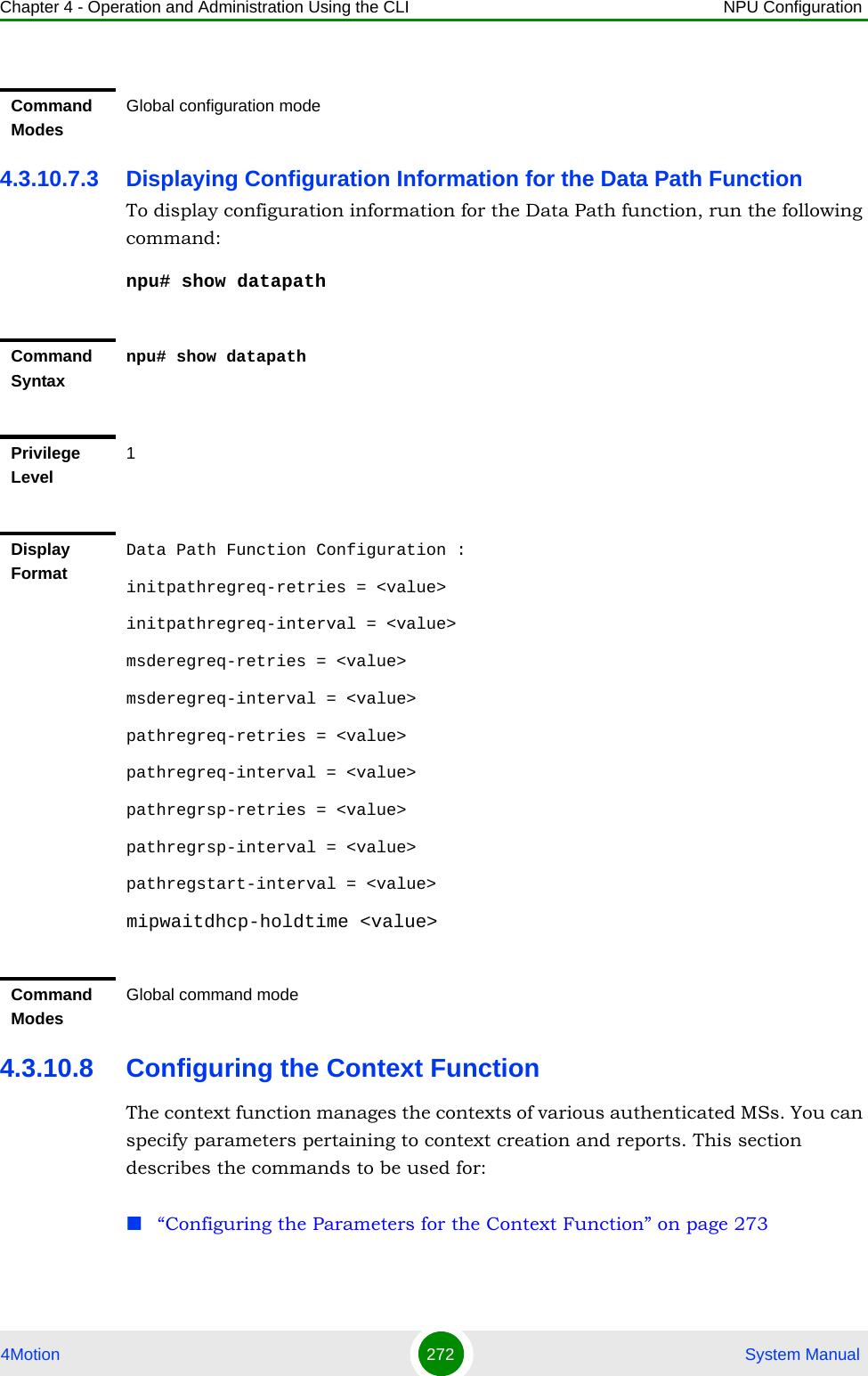
![Chapter 4 - Operation and Administration Using the CLI NPU Configuration4Motion 273 System Manual“Restoring the Default Configuration Parameters for the Context Function” on page 274“Displaying Configuration Information for the Context Function” on page 2754.3.10.8.1 Configuring the Parameters for the Context FunctionTo configure the parameters for the context function, run the following command:npu(config)# contextfn [contextreq-retries <retransmissions>] [contextreq-interval <timeout>] [contextrprt-retries <retransmissions>] [contextrprt-interval <timeout>]NOTEYou can display configuration information for the context function. For details, refer to Section 4.3.10.8.3IMPORTANTAn error may occur if you provide an invalid value for any of these parameters. Refer the syntax description for more information about the appropriate values and format for configuring these parameters.Command Syntaxnpu(config)# contextfn [contextreq-retries <retransmissions>] [contextreq-interval <timeout>] [contextrprt-retries <retransmissions>] [contextrprt-interval <timeout>]Privilege Level15Syntax Description Parameter Description Presence Default ValuePossible Values[contextreq-retries <retransmissions>]Denotes the maximum number of times the NPU will retransmit a context request. Optional 3 1-5](https://usermanual.wiki/Alvarion-Technologies/BMAX-OR-25.Manual-2/User-Guide-1114030-Page-177.png)
![Chapter 4 - Operation and Administration Using the CLI NPU Configuration4Motion 274 System Manual4.3.10.8.2 Restoring the Default Configuration Parameters for the Context FunctionTo restore the default configuration for the context function, run the following command:npu(config)# no contextfn [contextreq-retries] [contextreq-interval] [contextrprt-retries] [contextrprt-interval][contextreq-interval <timeout>]Denotes the period, in milliseconds, for which the NPU waits for a response to the context request. If the NPU does not receive a response to this request within the period specified by this timer, the NPU retransmits this request.Optional 10 5 - 100[contextrprt-retries <retransmissions>]Denotes the maximum number of times, the NPU retransmits the context report.Optional 3 0-5[contextrprt-interval <timeout>]Denotes the period, in milliseconds, for which the NPU waits for the context report acknowledgement. At the end of this period, the NPU retransmits the context report.Optional 3 0-5Command ModesGlobal configuration modeNOTERefer to Section 4.3.10.8.1 for a description and default values of these parameters. Command Syntaxnpu(config)# no contextfn [contextreq-retries] [contextreq-interval] [contextrprt-retries] [contextrprt-interval]Privilege Level15](https://usermanual.wiki/Alvarion-Technologies/BMAX-OR-25.Manual-2/User-Guide-1114030-Page-178.png)
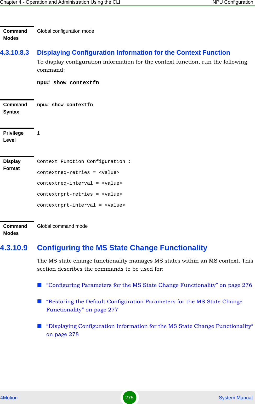
![Chapter 4 - Operation and Administration Using the CLI NPU Configuration4Motion 276 System Manual4.3.10.9.1 Configuring Parameters for the MS State Change Functionality To configure the parameters for the MS State Change functionality, run the following command:npu(config)# msscfn [msscrsp-retries <retransmissions>] [msscrsp-interval <timeout>] [sbc-holdtime <timeout>] [reg-holdtime <timeout>] [msscdrctv-retries <retransmissions>] [msscdrctv-interval <timeout>]NOTEYou can display configuration information for the MS state change functionality. For details, refer to Section 4.3.10.9.3.IMPORTANTAn error may occur if you provide an invalid value for any of these parameters. Refer the syntax description for more information about the appropriate values and format for configuring these parameters.Command Syntaxnpu(config)# msscfn [msscrsp-retries <retransmissions>] [msscrsp-interval <timeout>] [sbc-holdtime <timeout>] [reg-holdtime <timeout>] [msscdrctv-retries <retransmissions>] [msscdrctv-interval <timeout>]Privilege Level15Syntax Description Parameter Description Presence Default ValuePossible Values[msscrsp-retries <retransmissions>]Denotes the maximum number of times, the NPU retransmits the MS state change response.Optional 3 1-5[msscrsp-interval <timeout>]Denotes the period, in milliseconds for which the NPU waits for an acknowledgement for the MS state change response. If the NPU does not receive an acknowledgement within this period, it retransmits the MS state change response. Optional 10 5- 500](https://usermanual.wiki/Alvarion-Technologies/BMAX-OR-25.Manual-2/User-Guide-1114030-Page-180.png)
![Chapter 4 - Operation and Administration Using the CLI NPU Configuration4Motion 277 System Manual4.3.10.9.2 Restoring the Default Configuration Parameters for the MS State Change FunctionalityTo restore the default configuration for the MS State Change functionality, run the following command:npu(config)# no msscfn [msscrsp-retries] [msscrsp-interval] [sbc-holdtime] [reg-holdtime] [msscdrctv-retries] [msscdrctv-interval][sbc-holdtime <timeout>]Denotes the period, in milliseconds, within which the basic capabilities negotiation procedure should be completed. At the end of this period, the NPU starts the authentication/ registration procedure for the MS, depending on accepted authentication policy.Optional 5 0-100[reg-holdtime <timeout>]Denotes the interval, in seconds, for the MS registration procedure timeout. After this interval, the NPU changes the MS state to the registered state, and initiates the data path creation procedure (for authenticated MSs).Optional 5 0-100[msscdrctv-retries <retransmissions>]Denotes the maximum number of times, the NPU may retransmit the MS state change directive.Optional 3 0-5[msscdrctv-interval <timeout>Denotes the period, in milliseconds, for which the NPU waits for an acknowledgement for the MS state change directive. If the NPU does not receive an acknowledegment within this period, it retransmits the state change directive.Optional 10 0-500Command ModesGlobal configuration mode](https://usermanual.wiki/Alvarion-Technologies/BMAX-OR-25.Manual-2/User-Guide-1114030-Page-181.png)
![Chapter 4 - Operation and Administration Using the CLI NPU Configuration4Motion 278 System Manual4.3.10.9.3 Displaying Configuration Information for the MS State Change FunctionalityTo display configuration information for the MS state change functionality, run the following command:npu# show msscfnNOTERefer to Section 4.3.10.9.1 for a description and default values of these parameters. Command Syntaxnpu(config)# no msscfn [msscrsp-retries] [msscrsp-interval] [sbc-holdtime] [reg-holdtime] [msscdrctv-retries] [msscdrctv-interval]Privilege Level15Command ModesGlobal configuration modeCommand Syntaxnpu# show msscfnPrivilege Level1Display FormatMS State Change Function Configuration :msscrsp-retries = <value>msscrsp-interval = <value>sbc-holdtime = <value>reg-holdtime = <value>msscdrctv-retries = <value>msscdrctv-interval = <valueCommand ModesGlobal command mode](https://usermanual.wiki/Alvarion-Technologies/BMAX-OR-25.Manual-2/User-Guide-1114030-Page-182.png)
![Chapter 4 - Operation and Administration Using the CLI NPU Configuration4Motion 279 System Manual4.3.10.10 Configuring the Connectivity Service Network InterfaceThe Connectivity Service Network (CSN) interface provides IP connectivity services for a set of subscribers. The gateway uses the CSN interface for R3 control traffic and R3 data traffic towards the core network. You can configure the parameters for the IP interface to be used as the network interface for R3 control traffic. This section describes the commands to be used for: “Configuring Parameters for the CSN Interface” on page 279“Restoring the Default Configuration Parameters of the CSN Interface” on page 280“Displaying Configuration Information for the CSN Interface” on page 2814.3.10.10.1 Configuring Parameters for the CSN InterfaceTo configure the CSN parameters, run the following command:npu(config)# csnif [ip-intf <ip-intf>] [tun-mtu <size>] [tun-chksm]IMPORTANTSkip this task. The MIP functionality is not supported in the current release.NOTEYou can display configuration information for the CSN Interface. For details, refer to Section 4.3.10.10.3.IMPORTANTAn error may occur if you provide an invalid value for any of these parameters. Refer the syntax description for more information about the appropriate values and format for configuring these parameters.Command Syntaxnpu(config)# csnif [ip-intf <ip-intf>] [tun-mtu <size>] [tun-chksm]Privilege Level15](https://usermanual.wiki/Alvarion-Technologies/BMAX-OR-25.Manual-2/User-Guide-1114030-Page-183.png)
![Chapter 4 - Operation and Administration Using the CLI NPU Configuration4Motion 280 System Manual4.3.10.10.2 Restoring the Default Configuration Parameters of the CSN InterfaceTo restore the default configuration for the CSN interface, run the following command. This command can also be used to disable the tunnel-checksum feature.npu(config)# no csnif [tun-mtu] [tun-chksm]Syntax Description Parameter Description Presence Default ValuePossible Values[ip-intf <ip-intf>]Denotes a pre-defined IP interface to be used as a network interface for R3 control traffic and R3 data traffic.Note: If you are modifying the CSN interface, save the current configuration (refer Section 4.3.4.1) and reset the NPU (Section 4.2.2.1) for the change to take effect. Mandatory N/A bearer[tun-mtu <size>]Denotes the MTU for the IP-in-IP tunnel (used for R3 data traffic) on this interface.Optional 1450 1 - 232 -1[tun-chksm] Indicates that the tunnel checksum feature is enabled. If this feature is enabled, the checksum of the inner header is to be verified.Optional By default, this feature is disabled.The presence/absence of this parameter indicates that the tunnel checksum feature is enabled/disabled. Command ModesGlobal configuration modeNOTERefer to Section 4.3.10.10.1 for a description and default values of these parameters.](https://usermanual.wiki/Alvarion-Technologies/BMAX-OR-25.Manual-2/User-Guide-1114030-Page-184.png)
![Chapter 4 - Operation and Administration Using the CLI NPU Configuration4Motion 281 System Manual4.3.10.10.3 Displaying Configuration Information for the CSN InterfaceTo display configuration information for the CSN interface, run the following command:npu# show csnif4.3.10.11 Configuring Bearer Plane QoS Marking RulesThe bearer plane consists of tunnels between the ASN and CSN, and the BS and the NPU. R3 includes the bearer plane methods such as tunneling for enabling data transfer between the CSN and the ASN. R6 consists of the bearer plane protocols that implement the intra-ASN data path between the BS and the NPU. You can define QoS marking rules for the bearer plane, based on parameters such as traffic priority, and the type of service, media, and interface.Command Syntaxnpu(config)# no csnif [tun-mtu] [tun-chksm]Privilege Level15Command ModesGlobal configuration modeCommand Syntaxnpu# show csnifPrivilege Level1Display FormatCSN Interface Configuration :ip-intf = <value>tun-mtu = <value>tun-chksm = <value>Command ModesGlobal command mode](https://usermanual.wiki/Alvarion-Technologies/BMAX-OR-25.Manual-2/User-Guide-1114030-Page-185.png)
![Chapter 4 - Operation and Administration Using the CLI NPU Configuration4Motion 282 System ManualUp to a maximum of 21 Bearer Plane QoS Marking Rules can be defined. 1Enable the bearer plane QoS marking rules configuration mode (refer to Section 4.3.10.11.1)2You can now execute any of the following tasks:»Configure the output parameters for bearer plane QoS marking rules (refer to Section 4.3.10.11.2)»Restore the default parameters for bearer plane QoS marking rules (refer to Section 4.3.10.11.3)3Terminate the bearer plane QoS marking rules configuration mode (refer to Section 4.3.10.11.4)In addition, you can, at any time, display configuration information (refer to Section 4.3.10.11.6)or delete an existing bearer plane QoS marking rule (refer to Section 4.3.10.11.5). 4.3.10.11.1 Enabling the Bearer Plane QoS Marking Rule Configuration Mode\Creating a Bearer Plane QoS Marking RuleTo configure the parameters for the bearer plane QoS marking rules, first enable the bearer plane QoS marking rule configuration mode. Run the following command to enable the bearer plane QoS marking rules configuration mode. You can also use this command to create and enable the configuration mode for a new bearer plane QoS marking rule.npu(config)# bearerqos <qos-alias> [<intf-type((1<R3> - 0<R6> )| 255<ANY>)> <srvc-type(0<UGS> | 1<RTVR> | 2<NRTVR> | 3<BE> | 4<ERTVR> | 255<ANY>)> <trfc-priority((0-7)|255)> <media-type> ]To configure one or more QoS bearer plane marking rules:NOTEYou can display configuration information for the bearer plane QoS marking rules. For details, refer to Section 4.3.10.11.6.IMPORTANTAn error may occur if you provide an invalid value for any of these parameters. Refer the syntax description for more information about the appropriate values and format for configuring these parameters.](https://usermanual.wiki/Alvarion-Technologies/BMAX-OR-25.Manual-2/User-Guide-1114030-Page-186.png)
![Chapter 4 - Operation and Administration Using the CLI NPU Configuration4Motion 283 System ManualIf you use this command to create a new QoS marking rule, the configuration mode for this rule is automatically enabled, after which you can execute any of the following tasks:Configure the output parameters for bearer plane QoS marking rules (refer to Section 4.3.10.11.2)Restore the default parameters for bearer plane QoS marking rules (refer to Section 4.3.10.11.3)After executing the above tasks, you can terminate the bearer plane QoS marking rules configuration mode (refer to Section 4.3.10.11.4) and return to the global configuration mode.NOTEThe granularity of the QoS definition to be applied to packets transmitted on the bearer plane depends upon the number of parameters that you specify. If any parameter is to be excluded from the definition, specify the value 255 for that parameter.Command Syntaxnpu(config)# bearerqos <qos-alias> [<intf-type((1<R3> - 0<R6>)| 255<ANY>)> <srvc-type(0<UGS> | 1<RTVR> | 2<NRTVR> | 3<BE> | 4<ERTVR> | 255<ANY>)> <trfc-priority((0-7)|255)> <media-type>]Privilege Level10Syntax Description Parameter Description Presence Default ValuePossible Values<qos-alias> Denotes the QoS alias of the QoS marking rule for which you want to enable the bearer plane QoS marking rules configuration mode. If you want to create a new QoS marking rule, specify a new alias and define the type of interface, service, and traffic priority that is applicable for that rule.Mandatory N/A String (1 to 11 characters)](https://usermanual.wiki/Alvarion-Technologies/BMAX-OR-25.Manual-2/User-Guide-1114030-Page-187.png)
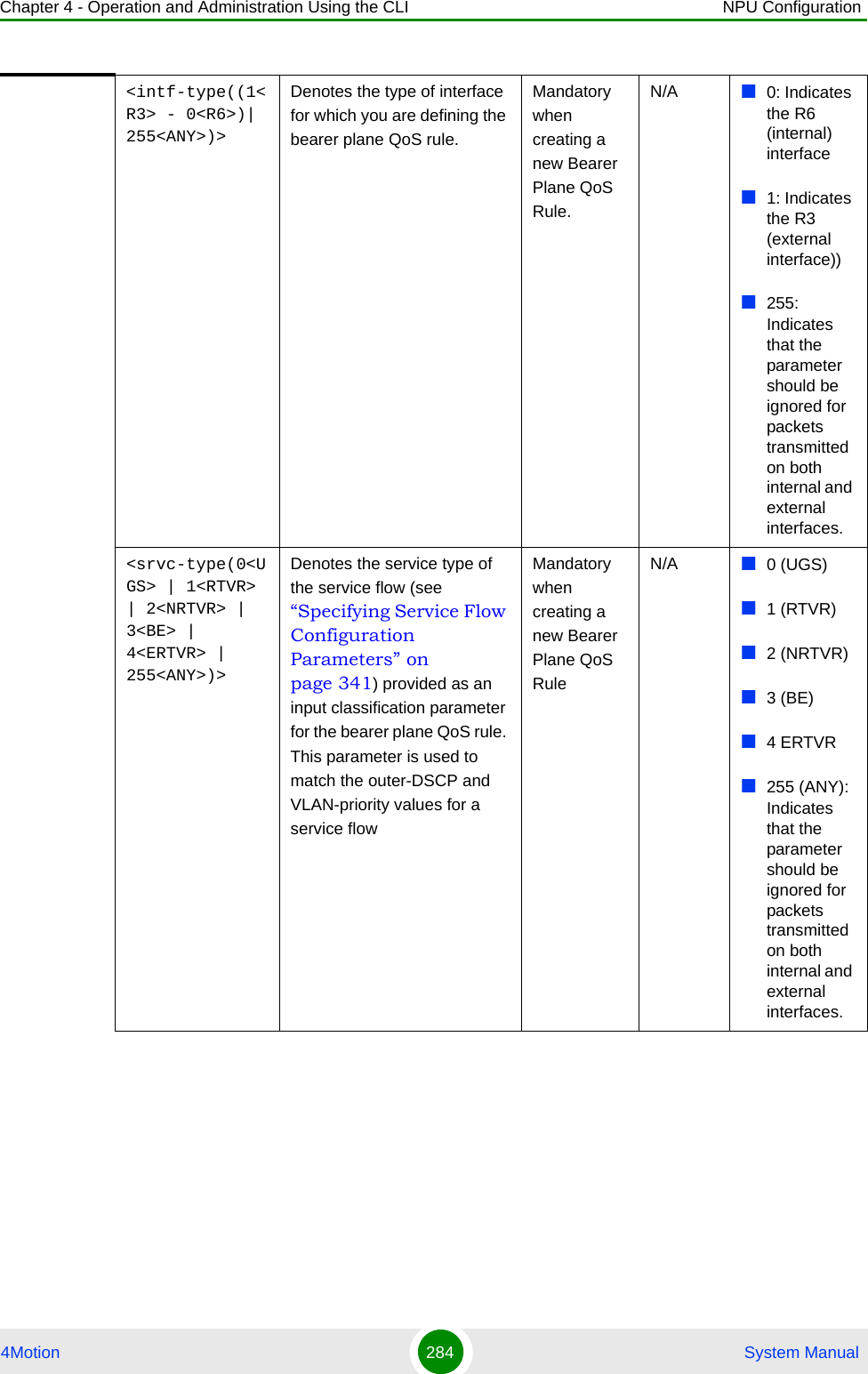
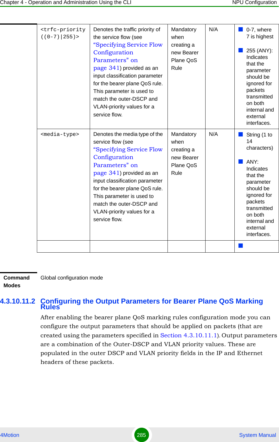
![Chapter 4 - Operation and Administration Using the CLI NPU Configuration4Motion 286 System ManualRun the following command to configure the output parameters for this bearer plane QoS marking rule:npu(config-bqos)# config [ outer-dscp <integer(0-63>] [vlan-priority <integer(0-7>] [qos enable]IMPORTANTEnable the bearer plane QoS marking rule that you are configuring. By default, all bearer plane QoS marking rules are disabled.NOTEYou can display configuration information for the bearer plane QoS marking rules. For details, refer to Section 4.3.10.11.6.IMPORTANTAn error may occur if you provide an invalid value for any of these parameters. Refer the syntax description for more information about the appropriate values and format for configuring these parameters.Command Syntaxnpu(config-bqos)# config [outer-dscp <integer(0-63>] [vlan-priority <integer(0-7>] [qos enable]Privilege Level10Syntax Description Parameter Description Presence Default ValuePossible Values[outer-dscp <integer(0-63>]Denotes the Differentiated Service Code Point (DSCP) value to be used for marking the packets, if the packet complies with the marking rules specified in Section 4.3.10.11.1.Optional 0 0-63[vlan-priority <integer(0-7>]Denotes the VLAN priority to be assigned to the packets if the packet meets the requirements of the marking rules specified in Section 4.3.10.11.1.Optional 0 0-7, where 7 is the highest](https://usermanual.wiki/Alvarion-Technologies/BMAX-OR-25.Manual-2/User-Guide-1114030-Page-190.png)
![Chapter 4 - Operation and Administration Using the CLI NPU Configuration4Motion 287 System Manual4.3.10.11.3 Restoring the Default Configuration Parameters for the Bearer Plane QoS Output Marking RulesRun the following command to restore the default configuration for this bearer plane QoS marking rule:npu(config-bqos)# no {outer-dscp | vlan-priority | qos enable}When you execute this command, it automatically disables this QoS marking rule.[qos enable] Indicates whether this QoS marking rule should be enabled. The absence of this flag indicates that this QoS flag is disabled. By default, a bearer plane QoS marking rule is disabled. If you enable this QoS marking rule, packets on bearer plane that were created using the parameters in Section 4.3.10.11.1, the Outer DSCP and VLAN Priority fields in the IP header and Ethernet header, respectively are populated with the values you specify for the outer-dscp and vlan-priority parameters.Optional By default, the QoS marking rule is disabled.The presence/absence of this flag indicates that this QoS flag is enabled/disabled. Command ModesBearer plane QoS marking rules configuration modeNOTERefer to Section 4.3.10.11.2 for a description and default values of these parameters. Command Syntaxnpu(config-bqos)# no {outer-dscp | vlan-priority | qos enable}Privilege Level10](https://usermanual.wiki/Alvarion-Technologies/BMAX-OR-25.Manual-2/User-Guide-1114030-Page-191.png)
![Chapter 4 - Operation and Administration Using the CLI NPU Configuration4Motion 288 System Manual4.3.10.11.4 Terminating the QoS Marking Rules Configuration ModeRun the following command to terminate the marking rules configuration mode:npu(config-bqos)# exit4.3.10.11.5 Deleting Bearer Plane QoS Marking RulesRun the following command to delete the a QoS marking rule:npu(config)# no bearerqos [<qos-alias>]Command ModesBearer plane QoS marking rules configuration modeCommand Syntaxnpu(config-bqos)# exitPrivilege Level10Command ModesBearer plane QoS marking rules configuration modeCAUTIONSpecify the QoS alias if you want to delete a specific bearer plane qoS marking rule. Otherwise all the configured bearer plane QoS marking rules are deleted.Command Syntaxnpu(config)# no bearerqos [<qos-alias>]Privilege Level10](https://usermanual.wiki/Alvarion-Technologies/BMAX-OR-25.Manual-2/User-Guide-1114030-Page-192.png)
![Chapter 4 - Operation and Administration Using the CLI NPU Configuration4Motion 289 System Manual4.3.10.11.6 Displaying Configuration Information for the Bearer Plane QoS Marking Rules To display configuration information for specific or all bearer plane QoS marking rules, run the following command:npu# show bearerqos [<qos-alias>]Specify the QoS alias if you want to display configuration information for a particular bearer plane QoS marking rule. Do not specify a value for this parameter if you want to view configuration information for all bearer plane QoS marking rules.Syntax Description Parameter Description Presence Default ValuePossible Values[<qos-alias>] Denotes the QoS alias of the bearer QoS marking rule that you want to delete. Specify a value for this parameter if you want to delete a specific bearer QoS marking rule. Do not specify a value for this parameter if you want to delete all bearer QoS marking rules.Optional N/A StringCommand ModesGlobal configuration modeCommand Syntaxnpu# show bearerqos [<qos-alias>]Privilege Level1](https://usermanual.wiki/Alvarion-Technologies/BMAX-OR-25.Manual-2/User-Guide-1114030-Page-193.png)
![Chapter 4 - Operation and Administration Using the CLI NPU Configuration4Motion 290 System Manual4.3.10.12 Managing Service InterfacesA Service Interface defines the parameters of the interface used by the NPU on the network side for services using the applicable Service Interface.Up to 10 Service Interfaces may be defined. 1Enable the Service Interface configuration mode for the selected Service Interface (refer to Section 4.3.10.12.1)Syntax Description Parameter Description Presence Default ValuePossible Values[<qos-alias>] Denotes the QoS alias of the bearer QoS marking rule that you want to display. Specify a value for this parameter if you want to display a specific bearer QoS marking rule. Do not specify a value for this parameter if you want to display all bearer QoS marking rules.Optional N/A StringDisplay FormatBearer QoS Configuration :qos-alias intf-type srvc-type trfc-priority media-type inner-dscp outer-dscp vlan-priority statusvoip <value> <value> <value> <value> <value> <value> enabledCommand ModesGlobal command modeTo configure a Service Interface:](https://usermanual.wiki/Alvarion-Technologies/BMAX-OR-25.Manual-2/User-Guide-1114030-Page-194.png)
![Chapter 4 - Operation and Administration Using the CLI NPU Configuration4Motion 291 System Manual2You can now execute any of the following tasks:»Configure one or more of the parameters of the Service Interface (refer to Section 4.3.10.12.2)»Restore the default values of the Service Interface parameters (refer to Section 4.3.10.12.3)» Terminate the Service Interface configuration mode (refer to Section 4.3.10.12.4)In addition, you can, at any time, display configuration information for one or all existing Service Interfaces (refer to Section 4.3.10.12.6) or delete an existing Service Interface (refer to Section 4.3.10.12.5). 4.3.10.12.1 Enabling the Service Interface Configuration Mode\Creating a Service InterfaceTo configure the parameters of a Service Interface, first enable the Service Interface configuration mode for the specific Service Interface. Run the following command to enable the Service Interface configuration mode. You can also use this command to create a new Service Interface. npu(config)# srvc-intf [<string>] [{IP-IP|VLAN|QinQ}]For example, to define a new IP-IP Service Interface named SI1, run the following command: npu(config)# srvc-intf SI1 IP-IPTo enable the configuration mode for an existing Service Interface named SI1, run the following command: npu(config)# srvc-intf SI1If you use this command to create a new Service Interface, the configuration mode for this Service Interface is automatically enabled.After enabling the configuration mode for a Service Interface you can execute any of the following tasks:Configure one or more of the Service Interface parameters (refer to Section 4.3.10.12.2)NOTEThe Bearer IP Interface (refer to “Configuring IP interfaces” on page 158) must be configured prior to creating IP-IP or VLAN service interfaces.](https://usermanual.wiki/Alvarion-Technologies/BMAX-OR-25.Manual-2/User-Guide-1114030-Page-195.png)
![Chapter 4 - Operation and Administration Using the CLI NPU Configuration4Motion 292 System ManualRestore the default values of non-mandatory parameters of the Service Interface (refer to Section 4.3.10.12.3)After executing the above tasks, you can terminate the Service Interface configuration mode (refer to Section 4.3.10.12.4) and return to the global configuration mode.4.3.10.12.2 Configuring Service Interface ParametersThis section describes the commands for:“Configuring Parameter for IP-IP Service Interface”“Configuring Parameter for VLAN Service Interface”“Configuring Parameter for QinQ Service Interface”Command Syntaxnpu(config)# srvc-intf [<string>] [{IP-IP|VLAN|QinQ}]Privilege Level10Syntax Description Parameter Description Presence Default Value Possible Values[<string>] The Service Interface alias of the Service Interface for which you want to enable the configuration mode. If you want to create a new Service Interface, specify a new alias and define the type of service interface (see below).Mandatory N/A String (1 to 15 characters)[{IP-IP|VLAN|QinQ}]The Service Interface’s type. Optional IP-IP IP-IPVLANQinQCommand ModesGlobal configuration mode](https://usermanual.wiki/Alvarion-Technologies/BMAX-OR-25.Manual-2/User-Guide-1114030-Page-196.png)
![Chapter 4 - Operation and Administration Using the CLI NPU Configuration4Motion 293 System Manual4.3.10.12.2.1 Configuring Parameter for IP-IP Service InterfaceAfter enabling the IP-IP Service Interface configuration mode, run the following command to configure the IP-IP service interface parameters:This command shall configure one or more parameters of the IP-IP Service Interface.npu(config-srvcif-ipip)# config ([descr <string>] [tun-srcaddr <ip4addr>] {tun-dstaddr <ipv4addr>} [tun-mtu <size(556-1804)>] [tun-chksm])Command Syntaxnpu(config-srvcif-ip-ip)# config ([descr <string>] [tun-srcaddr <ip4addr>] {tun-dstaddr <ipv4addr>} [tun-mtu <size(556-1804)>] [tun-chksm])Privilege Level10Syntax Description Parameter Description Presence Default ValuePossible Valuesconfig ([descr <string>]A description of the Service Interface.Optional null String (up to 70 characters)[tun-srcaddr <ip4addr>]The source IP address that indicates the point of origination of the tunnel for the service interface.Must be the same as the Bearer IP Address.Optional 0.0.0.0 Valid IP Address.](https://usermanual.wiki/Alvarion-Technologies/BMAX-OR-25.Manual-2/User-Guide-1114030-Page-197.png)
![Chapter 4 - Operation and Administration Using the CLI NPU Configuration4Motion 294 System Manual4.3.10.12.2.2 Configuring Parameter for VLAN Service InterfaceAfter enabling the VLAN Service Interface configuration mode, run the following command to configure the VLAN service interface parameters:This command shall configure one or more parameters of the VLAN Service Interface.npu(config-srvcif-vlan)# config ([descr <string>] [ServiceIfVlanId <integer(1-4094>] [ServiceIfDfltGwIp <ipv4addr>] [tun-mtu <integer(556-1804)>]){tun-dstaddr <ipv4addr>}The destination IP address that indicates the point of termination of the tunnel for the service interface. Shall be unique among all the Host Interfaces IP's (Bearer, Local-Management, Internal-Management, External-Management) and existing instances of Service Interface’s Tunnel Destination IP Address and Default Gateway IP Address. Shall not be in the subnet of any Mgmt interface (ie. Local, External and Internal).Optional 0.0.0.0 Valid IP Address.[tun-mtu <size(556-1804)>]Denotes the MTU. Optional 1480 556-1804[tun-chksm] Indicates that end-to-end checksumming mechanism on ServiceTunnel Interface is enabled.Optional By default, this feature is disabled.The presence/absence of this flag indicates that this feature is enabled/ disabled.Command ModesIP-IP Service Interface configuration modeCommand Syntaxnpu(config-srvcif-vlan)# config ([descr <string>] [ServiceIfVlanId <integer(1-4094>] [ServiceIfDfltGwIp <ipv4addr>] [tun-mtu <integer(556-1804)>])](https://usermanual.wiki/Alvarion-Technologies/BMAX-OR-25.Manual-2/User-Guide-1114030-Page-198.png)
![Chapter 4 - Operation and Administration Using the CLI NPU Configuration4Motion 295 System ManualPrivilege Level10Syntax Description Parameter Description Presence Default ValuePossible Valuesconfig [descr <string>] Aa description of the service interface.Optional null String (up to 70 characters)ServiceIfVlanId <integer(1-4094>]A Service Interface VLAN ID shall not conflict with other instances of Service Interface VLAN ID and VLAN IDs of Bearer, Local-Management and External-Management interaces. Shall also not conflict with CVID of any transparent MS.Optional 0 0-9, 11-4094[ServiceIfDfltGwIp <ipv4addr>]The IP Address of the Default Gateway.Shall be unique among all the Host Interfaces IP's (Bearer, Local-Management, Internal-Management, External-Management) and existing instances of Service Interface’s Tunnel Destination IP Address and Default Gateway IP Address.Should be in the same subnet.with the IP Address of the DHCP server/proxy/relay to be assigned to a service group using this service interface. Subnet mask is taken as default subnet mask i.e 255.255.255.0.Optional 0.0.0.0 valid IP address[tun-mtu <integer(556-1804)>] The MTU Optional 1480 556-1804Command ModesVLAN Service Interface configuration mode](https://usermanual.wiki/Alvarion-Technologies/BMAX-OR-25.Manual-2/User-Guide-1114030-Page-199.png)
![Chapter 4 - Operation and Administration Using the CLI NPU Configuration4Motion 296 System Manual4.3.10.12.2.3 Configuring Parameter for QinQ Service InterfaceAfter enabling the QinQ Service Interface configuration mode, run the following command to configure the QinQ service interface parameters:This command shall configure one or more parameters of the QinQ Service Interface.npu(config-srvcif-QinQ)# config ([descr <string>] [ServiceIfVlanId <integer(1-4094>])4.3.10.12.3 Restoring the Default Configuration Parameters for a Service InterfaceThis section describes the commands for:“Restoring the Default Configuration Parameters for an IP-IP Service Interface”“Restoring the Default Configuration Parameters for a VLAN Service Interface”Command Syntaxnpu(config-srvcif-QinQ)# config ([descr <string>] [ServiceIfVlanId <integer(1-4094>]])Privilege Level10Syntax Description Parameter Description Presence Default ValuePossible Valuesconfig [descr <string>] A description of the service interface.Optional null String (up to 70 characters)ServiceIfVlanId <integer(1-4094>]A Service Interface VLAN ID shall not conflict with other instances of Service Interface VLAN ID and VLAN IDs of Bearer, Local-Management and External-Management interaces. Shall also not conflict with CVID of any transparent MS.Optional 0 0-9, 11-4094Command ModesQinQ Service Interface configuration mode](https://usermanual.wiki/Alvarion-Technologies/BMAX-OR-25.Manual-2/User-Guide-1114030-Page-200.png)
![Chapter 4 - Operation and Administration Using the CLI NPU Configuration4Motion 297 System Manual4.3.10.12.3.1 Restoring the Default Configuration Parameters for an IP-IP Service InterfaceRun the following command to restore the default configuration for IP-IP service interface tun-mtu and/or tun-chksm parameters:npu(config-srvcif-ipip)# no [tun-mtu] [tun-chksm]You can restore only one parameter to its default values by specifying only that parameter. To restore both parameters to their default value, run the command npu(config-srvcif-ipip)# no.4.3.10.12.3.2 Restoring the Default Configuration Parameters for a VLAN Service InterfaceRun the following command to restore the default configuration for a VLAN service interface tun-mtu parameter:npu(config-srvcif-vlan)# no [tun-mtu]NOTERefer to Section 4.3.10.12.2.1 for a description and default values of these parameters. Command Syntaxnpu(config-srvcif-ipip)# no [tun-mtu] [tun-chksm]Privilege Level10Command ModesIP-IP Service Interface configuration modeNOTERefer to Section 4.3.10.12.2.2 for a description and default values of this parameter. Command Syntaxnpu(config-srvcif-vlan)# no [tun-mtu]Privilege Level10Command ModesVLAN Service Interface configuration mode](https://usermanual.wiki/Alvarion-Technologies/BMAX-OR-25.Manual-2/User-Guide-1114030-Page-201.png)
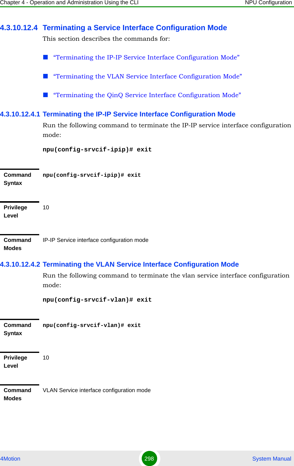
![Chapter 4 - Operation and Administration Using the CLI NPU Configuration4Motion 299 System Manual4.3.10.12.4.3 Terminating the QinQ Service Interface Configuration ModeRun the following command to terminate the QinQ service interface configuration mode:npu(config-srvcif-QinQ)# exit4.3.10.12.5 Deleting a Service InterfaceYou can, at any time, run the following command to delete service interface:npu(config)# no srvc-intf [<intf-alias>]Command Syntaxnpu(config-srvcif-QinQ)# exitPrivilege Level10Command ModesQinQ Service interface configuration modeNOTEA Service Interface cannot be deleted if it is assigned to any Service Group.A QinQ Service Interface cannot be deleted if it is assigned to a Service Flow (with a VPWS-QinQ Service Group). For details refer to “Configuring Service Flows” on page 339.Command Syntaxnpu(config)# no srvc-intf [intf-alias>]Privilege Level10Syntax Description Parameter Description Presence Default ValuePossible Values[intf-alias>]The alias of the Service interface which needs to be deletedMandatory N/A String](https://usermanual.wiki/Alvarion-Technologies/BMAX-OR-25.Manual-2/User-Guide-1114030-Page-203.png)
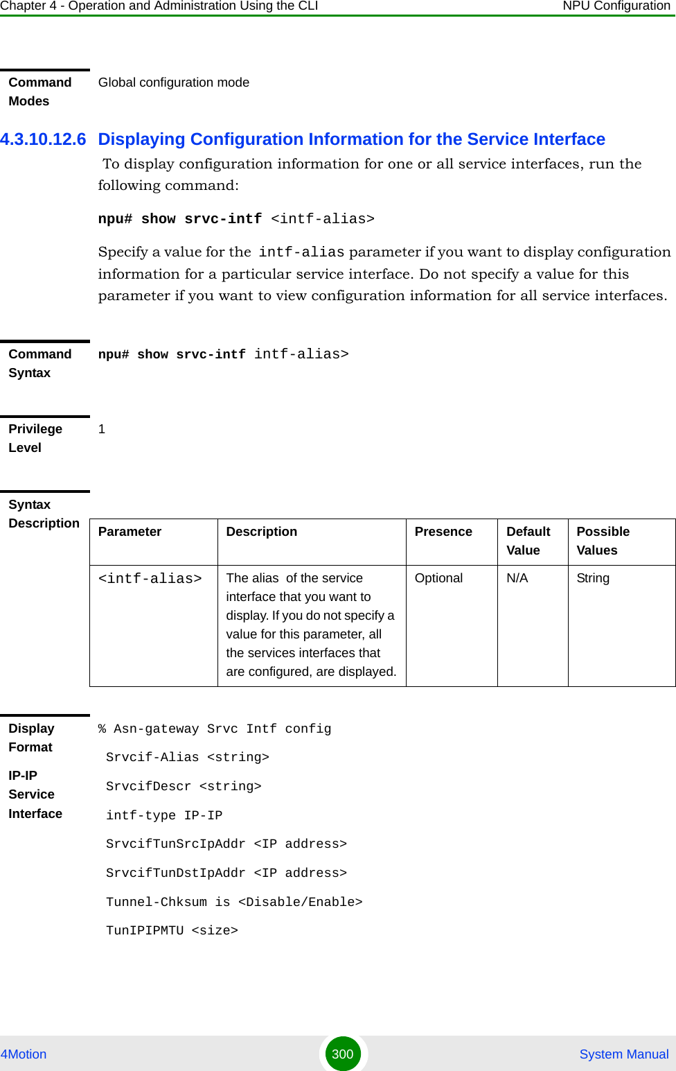
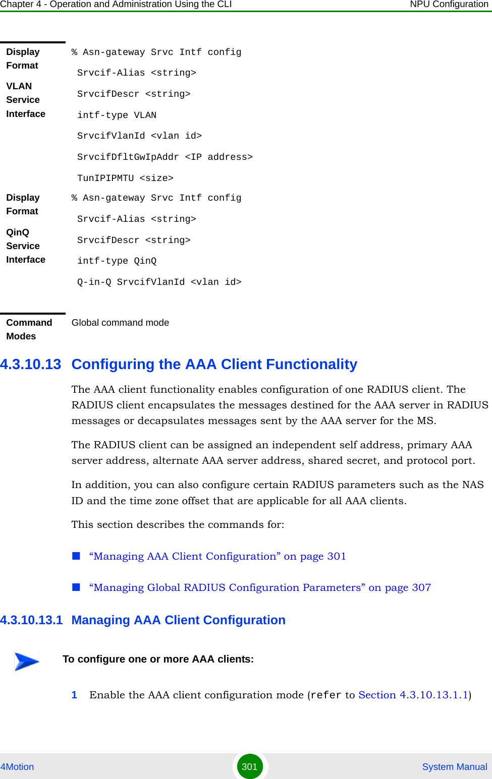
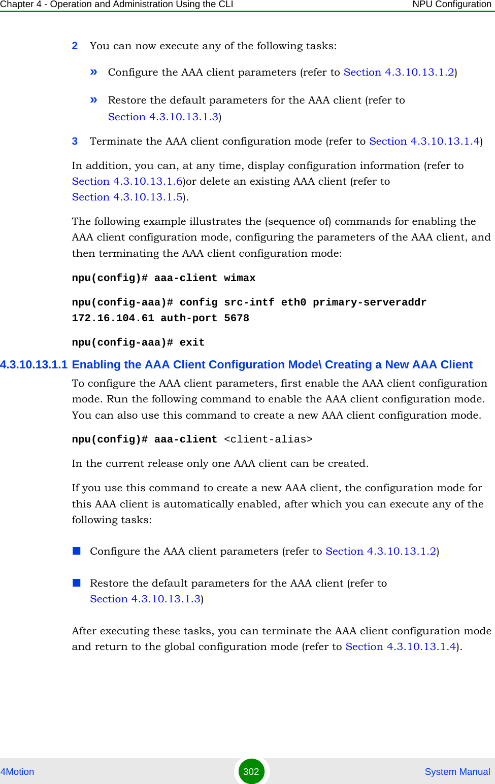
![Chapter 4 - Operation and Administration Using the CLI NPU Configuration4Motion 303 System Manual4.3.10.13.1.2 Configuring Parameters for the AAA ClientAfter enabling the AAA client configuration mode, run the following command to configure the parameters for the AAA client:npu(config-aaa)# config [src-intf <ip-intf>] [primary-serveraddr <ipv4addr>] [alternate-serveraddr <ipv4addr>] [rad-sharedsecret <string>] [auth-port <port>] [acct-port <port>]Command Syntaxnpu(config)# aaa-client <client-alias>Privilege Level10Syntax Description Parameter Description Presence Default ValuePossible Values<client-alias> Denotes the client-alias of the AAA client for which the configuration mode is to be enabled. If you want to create a new AAA client, specify the client-alias for the AAA client that you want to create.Mandatory N/A StringCommand ModesGlobal configuration modeNOTEYou can display configuration information for a specific or all AAA clients. For details, refer to Section 4.3.10.13.1.6.IMPORTANTAn error may occur if you provide an invalid value for any of these parameters. Refer the syntax description for more information about the appropriate values and format for configuring these parameters.](https://usermanual.wiki/Alvarion-Technologies/BMAX-OR-25.Manual-2/User-Guide-1114030-Page-207.png)
![Chapter 4 - Operation and Administration Using the CLI NPU Configuration4Motion 304 System ManualCommand Syntaxnpu(config-aaa)# config [src-intf <ip-intf>] [primary-serveraddr <ipv4addr>] [alternate-serveraddr <ipv4addr>] [rad-sharedsecret <string>] [auth-port <port>] [acct-port <port>]Privilege Level10Syntax Description Parameter Description Presence Default ValuePossible Values[src-intf <ip-intf>]Indicates the IP address of the interface providing RADIUS client functionality. Must be the IP address of the Bearer interface.Note: If you are modifying the service interface for the AAA client, save the current configuration (refer Section 4.3.4.1) and reset the NPU (Section 4.2.2.1) for the change to take effect. Mandatory N/A IP address of bearer interface[primary-serveraddr <ipv4addr>]Denotes IPv4 address of the primary AAA server. It is mandatory to specify a value for this parameter if you do not configure an alternate server.Optional 0.0.0.0 Valid IP Address[alternate-serveraddr <ipv4addr>]Denotes IPv4 address of the alternate AAA server.It is mandatory to specify a value for this parameter if you do not configure a primary server.Optional N/A Valid IP Address[rad-sharedsecret <string>]Denotes the shared secret between the AAA client and the AAA server. Mandatory N/A String (1 to 49 characters)[auth-port <port>]Denotes the Authenticator port on which the AAA client listens to and sends RADIUS authentication messages. Optional 1812 0-65535](https://usermanual.wiki/Alvarion-Technologies/BMAX-OR-25.Manual-2/User-Guide-1114030-Page-208.png)
![Chapter 4 - Operation and Administration Using the CLI NPU Configuration4Motion 305 System Manual4.3.10.13.1.3 Restoring the Default Configuration Parameters for the Authentication PortRun the following command to restore the default configuration for the authentication port.npu(config-aaa)# no [primary-serveraddr] [alternate-serveraddr] [auth-port] [acct-port <port>]When you execute this command for restoring the default values, it also deletes the current values for the primary-server and alternate-server address.4.3.10.13.1.4 Terminating the AAA Client Configuration ModeRun the following command to terminate the AAA client configuration mode:npu(config-aaa)# exit[acct-port <port>]Denotes the accounting port on which the AAA client listens to and sends RADIUS accounting messages.Optional 1813 0-65535Command ModesAAA client configuration modeNOTERefer to Section 4.3.10.2.1 for a description and default values of these parameters. Command Syntaxnpu(config-aaa)# no [primary-serveraddr] [alternate-serveraddr] [auth-port] [acct-port <port>]Privilege Level10Command ModesAAA client configuration modeCommand Syntaxnpu(config-aaa)# exitPrivilege Level10](https://usermanual.wiki/Alvarion-Technologies/BMAX-OR-25.Manual-2/User-Guide-1114030-Page-209.png)
![Chapter 4 - Operation and Administration Using the CLI NPU Configuration4Motion 306 System Manual4.3.10.13.1.5 Deleting the AAA ClientRun the following command to delete the AAA client:npu(config)# no aaa-client [<client-alias>]4.3.10.13.1.6 Displaying Configuration Information for the AAA Client To display one or all AAA clients, run the following command:npu# show aaa-client [<client-alias>]Specify the AAA client alias if you want to display configuration information for a particular AAA client. Do not specify a value for this parameter if you want to view configuration information for all AAA clients.Command ModesAAA client configuration modeCAUTIONSpecify the AAA client alias if you want to delete a specific AAA client. Otherwise all the configured AAA clients are deleted.In the current release, only one AAA client can be configured.Command Syntaxnpu(config)# no aaa-client [<client-alias>]Privilege Level10Syntax Description Parameter Description Presence Default ValuePossible Values[<client-alias>]Denotes the AAA client that is to be deleted. If you do not specify a value for this parameter, all the existing AAA clients, are deleted.Optional N/A StringCommand ModesGlobal configuration mode](https://usermanual.wiki/Alvarion-Technologies/BMAX-OR-25.Manual-2/User-Guide-1114030-Page-210.png)
![Chapter 4 - Operation and Administration Using the CLI NPU Configuration4Motion 307 System Manual4.3.10.13.2 Managing Global RADIUS Configuration ParametersGlobal RADIUS configuration parameters for AAA clients determine how AAA clients should send access requests. This section describes the commands to be used for: “Configuring Global RADIUS Parameters” on page 308“Restoring the Default Global RADIUS Configuration Parameters” on page 309Command Syntaxnpu# show aaa-client [<client-alias>]Privilege Level1Syntax Description Parameter Description Presence Default ValuePossible Values[<client-alias>]Denotes the client-alias for which the associated AAA client information is to be displayed. Specify a value for this parameter if you want to display information about a specific AAA client.If you want to display information about all AAA clients, do not specify any value for this parameter. Optional N/A StringDisplay FormatAAA Client Configuration :client-alias src-intf primary-servweraddr alternate-serveraddr rad-sharedsecret auth-port acct-port<value> <value> <value> <value> <value> <value>Command ModesGlobal command mode](https://usermanual.wiki/Alvarion-Technologies/BMAX-OR-25.Manual-2/User-Guide-1114030-Page-211.png)
![Chapter 4 - Operation and Administration Using the CLI NPU Configuration4Motion 308 System Manual“Displaying Global RADIUS Configuration Parameters” on page 3104.3.10.13.2.1 Configuring Global RADIUS ParametersTo configure the global RADIUS configuration parameters to be used for all AAA clients, run the following command:npu(config)# radius <[accessreq-retries <retransmissions>] [accessreq-interval <timeout>] [nasid <nas-identifier>] [timezone-offset <time-offset(0-86400)>] [mtu <framed mtu size(1020-2000)>][RadiusAtrbtTypeServiceProfileName <AtrbtTypeId(1-255)>]>NOTEYou can display configuration information for global RADIUS parameters. For details, refer to Section 4.3.10.13.2.3IMPORTANTAn error may occur if you provide an invalid value for any of these parameters. Refer the syntax description for more information about the appropriate values and format for configuring these parameters.Command Syntaxnpu(config)# radius <[accessreq-retries <retransmissions>] [accessreq-interval <timeout>] [nasid <nas-identifier>] [timezone-offset <time-offset(0-86400)>] [mtu <framed mtu size(1020-2000)>] [RadiusAtrbtTypeServiceProfileName <AtrbtTypeId(1-255)>]>Privilege Level10Syntax Description Parameter Description Presence Default ValuePossible Values[accessreq-retries <retransmissions>]Denotes the maximum number of times the AAA client can resend the access request.Optional 3 0-5[accessreq-interval <timeout>]Denotes the interval, in seconds, after which the AAA client can resend the access request.Optional 500 10-100000](https://usermanual.wiki/Alvarion-Technologies/BMAX-OR-25.Manual-2/User-Guide-1114030-Page-212.png)
![Chapter 4 - Operation and Administration Using the CLI NPU Configuration4Motion 309 System Manual4.3.10.13.2.2 Restoring the Default Global RADIUS Configuration ParametersTo restore the default global RADIUS configuration used for AAA clients, run the following command:npu(config)# no radius [accessreq-retries] [accessreq-interval] [nasid] [timezone-offset] [mtu][nasid <nas-identifier>]Denotes the unique identifier of the ASNGW NAS. Sent in Access Request message only if configured. Should be in FQDN format.Optional null String (up to 64 characters)[timezone-offset <time-offset(0-86400)>]Denotes the time zone offset, in seconds, from GMT at the NAS.Optional 0 0-86400[mtu <framed mtu size(1020-2000)>]Denotes the MTU to be used for the AAA client functionality.Optional 2000 1020-2000[RadiusAtrbtTypeServiceProfileName <AtrbtTypeId(1-255)>]Denotes the RADIUS attribute in which the ASN-GW shall expect to get the service profile name. For example, configure 11 if AAA uses Filter ID as the container of service profile name,Use only unassigned freetext-type RADIUS attributes.Optional 11 1-255Command ModesGlobal configuration modeNOTERefer Section 4.3.10.13.2.1 for a description and default values of these parameters. Command Syntaxnpu(config)# no radius [accessreq-retries] [accessreq-interval] [nasid] [timezone-offset] [mtu]](https://usermanual.wiki/Alvarion-Technologies/BMAX-OR-25.Manual-2/User-Guide-1114030-Page-213.png)
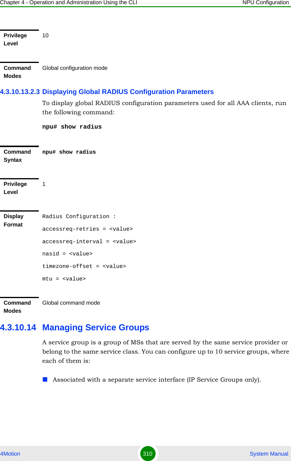
![Chapter 4 - Operation and Administration Using the CLI NPU Configuration4Motion 311 System ManualConfigured as any one of the following:»DHCP server that allocates an IP address to the MS from the local pool (in the non-HA mode).»DHCP relay that obtains the IP address using an external DHCP server (in the non-HA mode).»DHCP proxy for either of the following boot modes:◊Non-HA mode: The DHCP proxy assigns the MS, the IP address that was received from AAA in the MS profile or ◊HA mode: The DHCP proxy assigns the MS, the IP address received in the MS profile or obtains the IP address from HA using the mobile IP1Enable the service group configuration mode (refer to Section 4.3.10.14.1)2You can now execute any of the following tasks:»Configure the common parameters of a service group (refer to Section 4.3.10.14.2)»Enable the service group operation mode and configure the DHCP server/proxy/relay-specific parameters (refer to Section 4.3.10.14.4.1)3Terminate the service group configuration mode (refer to Section 4.3.10.14.5)In addition, you can, at any time, display configuration information (refer to Section 4.3.10.15.2) or delete an existing service group (refer to Section 4.3.10.14.6). 4.3.10.14.1 Enabling the Service Group Configuration Mode\ Creating a New Service GroupTo configure the parameters for the service group, first enable the service group configuration mode. Run the following command to enable the service group configuration mode or create the service group.npu(config)# srvc-grp <grp-alias> [ServiceGrpType {IP | VPWS-QinQ | VPWS-Transparent}]If you use this command to create a new service group, the configuration mode for this group is automatically enabled after which you can configure or restore the default parameters for this service group.To configure a service group:](https://usermanual.wiki/Alvarion-Technologies/BMAX-OR-25.Manual-2/User-Guide-1114030-Page-215.png)
![Chapter 4 - Operation and Administration Using the CLI NPU Configuration4Motion 312 System ManualAfter enabling the service group configuration mode, you can execute any of the following tasks:Configure the common parameters for the service group (refer to Section 4.3.10.14.2)Enable the service group operation mode and configure the DHCP server/proxy/relay-specific parameters (refer to Section 4.3.10.14.4.1)After executing these tasks, you can terminate the service group configuration mode (refer to Section 4.3.10.14.5).NOTEYou can display configuration information for specific or all service groups. For details, refer to Section 4.3.10.15.2.Command Syntaxnpu(config)# srvc-grp <grp-alias> [ServiceGrpType {IP | VPWS-QinQ | VPWS-Transparent}]Privilege Level10Syntax Description Parameter Description Presence Default ValuePossible Values<grp-alias> Denotes the group-alias of the service group for which the service group configuration mode is to be enabled. If you want to create a new service group, specify the group alias to be assigned to the srevice group.Mandatory N/A String (1 to 15 characters)[ServiceGrpType {IP | VPWS-QinQ | VPWS-Transparent} ]The Service group’s type. Optional IP IPVPWS-QinQVPWS-Transparent](https://usermanual.wiki/Alvarion-Technologies/BMAX-OR-25.Manual-2/User-Guide-1114030-Page-216.png)
![Chapter 4 - Operation and Administration Using the CLI NPU Configuration4Motion 313 System Manual4.3.10.14.2 Configuring Common Parameters of a Service GroupAfter enabling the service group configuration mode, run the following command to configure common parameters for the service group:npu(config-srvcgrp)# config {{[srvcif-alias <service interface>] [waitdhcp-holdtime <timeout>] [dhcp-ownaddr <ipv4addr>]} | {dhcp-server|dhcp-proxy|dhcp-relay} |{[<ServiceGrpIfAccounting (enable|disable)>]}|{[<ServiceGrpIfMSLoopBack (enable|disable)>]}}This commands comprises 4 sub-commands:1npu(config-srvcgrp)# config {[srvcif-alias <service interface>] [waitdhcp-holdtime <timeout>] [dhcp-ownaddr <ipv4addr>]} 2npu(config-srvcgrp)# config {dhcp-server|dhcp-proxy|dhcp-relay}3npu(config-srvcgrp)# config {[<ServiceGrpIfAccounting (enable|disable)>]}4npu(config-srvcgrp)# config {[<ServiceGrpIfMSLoopBack (enable|disable)>]}Command ModesGlobal configuration modeNOTEThis command is applicable for an IP Service Group. In VPWS-QinQ and VPWS-Transparent Service Groups only the accounting option (ServiceGrpIfAccounting (enable|disable)) is available.NOTEYou can display configuration information for the service group. For details, refer to Section 4.3.10.15.2.IMPORTANTAn error may occur if you provide an invalid value for any of these parameters. Refer the syntax description for more information about the appropriate values and format for configuring these parameters.Command Syntaxnpu(config-srvcgrp)# config {{[srvcif-alias <service interface>] [waitdhcp-holdtime <timeout>] [dhcp-ownaddr <ipv4addr>]} | {dhcp-server|dhcp-proxy|dhcp-relay} |{[<ServiceGrpIfAccounting (enable|disable)>]}|{[<ServiceGrpIfMSLoopBack (enable|disable)>]}}](https://usermanual.wiki/Alvarion-Technologies/BMAX-OR-25.Manual-2/User-Guide-1114030-Page-217.png)
![Chapter 4 - Operation and Administration Using the CLI NPU Configuration4Motion 314 System ManualPrivilege Level10Syntax Description Parameter Description Presence Default ValuePossible Values[srvcif-alias <service interface>]Denotes the pre-defined service interface alias to be used as the data path for traffic towards the core network.Note that a Service Interface alias can be associated only to a single Service Group.Mandatory N/A String[waitdhcp-holdtime <timeout>]Denotes the period, in seconds, for which the NPU waits for an IP address allocation trigger (MIP registration request / DHCP discover) from the MS. If you specify the value of this parameter as 0, no timer is started and the NPU will wait infinitely for the IP address allocation trigger.Optional 0 0-86400](https://usermanual.wiki/Alvarion-Technologies/BMAX-OR-25.Manual-2/User-Guide-1114030-Page-218.png)
![Chapter 4 - Operation and Administration Using the CLI NPU Configuration4Motion 315 System Manual4.3.10.14.3 Enabling/Disabling VLAN Service InterfaceRun the following commands to enable/disable the creation of a data-path for a VLAN Service:To enable: npu(config-srvcgrp)# config {[serviceVlanEnable]}To disable: npu(config-srvcgrp)# no serviceVlanEnable[dhcp-ownaddr <ipv4addr>]Denotes the IPv4 address of the DHCP server/ relay/ proxy.For a service group using a VLAN service interface, should be in same subnet with the Default Gateway configured for the service interface associated with the service group. Subnet mask is taken as the default subnet mask i.e 255.255.255.0.Note: In DHCP Server mode, the DHCP server IP address must be in the same subnet but outside the range allocated for users address pool as provisioned in the DHCP Server.Mandatory N/A Valid IP Address{dhcp-server|dhcp-proxy|dhcp-relay}Mode of IP address allocation used for subscribers: DHCP Server/ Proxy/ Relay.Mandatory N/A dhcp-serverdhcp-proxydhcp-relay{ServiceGrpIfAccounting {enable| disable}}Denotes whether accounting is enabled or disabled for the service interface.Optional Enable EnableDisable{ServiceGrpIfMsLoopBack {enable| disable}}Denotes whether MS loopback is enabled or disabled for the service interfaceOptional Disable EnableDisableCommand ModesService group configuration mode](https://usermanual.wiki/Alvarion-Technologies/BMAX-OR-25.Manual-2/User-Guide-1114030-Page-219.png)
![Chapter 4 - Operation and Administration Using the CLI NPU Configuration4Motion 316 System Manual4.3.10.14.4 Configuring the DHCP Server/Proxy/Relay 1Enable the service group operation mode for DHCP server/relay/proxy (refer to Section 4.3.10.14.4.1)2You can now execute one of the following tasks according to the selected DHCP mode:»Configure the DHCP server (refer to Section 4.3.10.14.4.2)»Configure the DHCP proxy (refer to Section 4.3.10.14.4.3)»Configure the DHCP relay (refer to Section 4.3.10.14.4.4)4.3.10.14.4.1 Enabling the Service Group Operation Mode for DHCP Server//Proxy/RelayRun the following command enable the DHCP (server/relay/proxy) configuration mode.npu(config-srvcgrp)# config {dhcp-server|dhcp-proxy|dhcp-relay}When you run this command, the DHCP server/proxy/relay configuration mode is enabled, after which you can execute the following tasks:Configure the DHCP server (refer to Section 4.3.10.14.4.2)Configure the DHCP proxy (refer to Section 4.3.10.14.4.3)Configure the DHCP relay (refer to Section 4.3.10.14.4.4)Command Syntaxnpu(config-srvcgrp)# config {[serviceVlanEnable]}npu(config-srvcgrp)# no [<servicevlanEnable>Privilege Level10Command ModesService group configuration modeTo configure the DHCP server/proxy/relay:](https://usermanual.wiki/Alvarion-Technologies/BMAX-OR-25.Manual-2/User-Guide-1114030-Page-220.png)
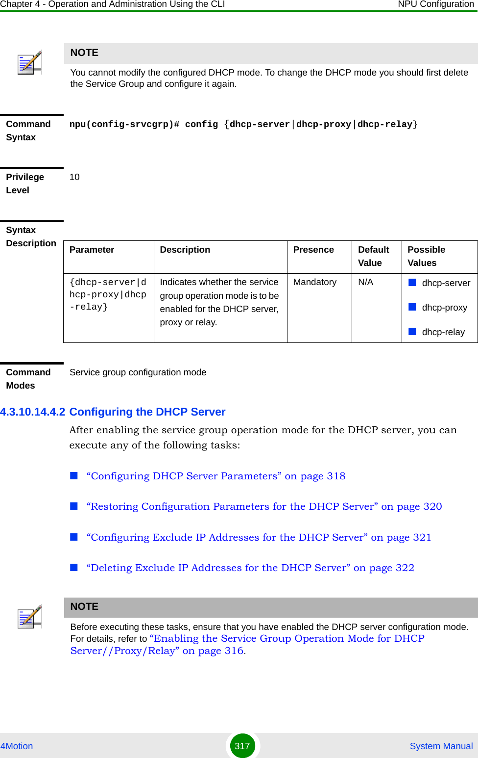
![Chapter 4 - Operation and Administration Using the CLI NPU Configuration4Motion 318 System Manual4.3.10.14.4.2.1Configuring DHCP Server ParametersRun the following command to configure the DHCP server:npu(config-srvcgrp-dhcpserver)# config ([pool-minaddr <string>] [pool-maxaddr <string>] [pool-subnet <string>] [dflt-gwaddr <string>] [lease-interval <integer(24-2147483647)>] [renew-interval <integer>] [rebind-interval <integer>] [dnssrvr-addr <string>] [offerreuse-holdtime <integer>] [opt60 <string(30)>] [opt43 {[Name <string(64)>] [Value <string(64)>]}] [Sname <string(64)>] [File <string(128)>])NOTEIf DHCP IP pool (pool-minaddr and/or pool-maxaddr) need to be changed, the service group should be deleted and reconfigured with the new DHCP IP pool.IMPORTANTAn error may occur if you provide an invalid value for any of these parameters. Refer the syntax description for more information about the appropriate values and format for configuring these parameters.Command Syntaxnpu(config-srvcgrp-dhcpserver)# config ([pool-minaddr <string>] [pool-maxaddr <string>] [pool-subnet <string>] [dflt-gwaddr <string>] [lease-interval <integer(24-2147483647)>] [renew-interval <integer>] [rebind-interval <integer>] [dnssrvr-addr <string>] [offerreuse-holdtime <integer>] [opt60 <string(30)>] [opt43 {[Name <string(64)>] [Value <string(64)>]}] [Sname <string(64)>] [File <string(128)>])Privilege Level10Syntax Description Parameter Description Presence Default ValuePossible Values[pool-minaddr <string>]Denotes the minimum (lowest) IP address of the address pool to be used for address allocation for MSs from this Service Group.Optional 0.0.0.0 Valid IP Address](https://usermanual.wiki/Alvarion-Technologies/BMAX-OR-25.Manual-2/User-Guide-1114030-Page-222.png)
![Chapter 4 - Operation and Administration Using the CLI NPU Configuration4Motion 319 System Manual[[pool-maxaddr <string>] Denotes the maximum (highest) IP address of the address pool configuration.Optional 255.255.255.255Valid IP Address[pool-subnet <string>]The IP subnet mask to be provided by local DHCP Service with IP address for MSs from this Service Group.Optional 255.255.255.255IP subnet[dflt-gwaddr <string>]IP address of Default Gateway to be provided by local DHCP Service with IP address for MS from this Service Group.Optional 0.0.0.0 Valid IP Address[lease-interval <integer(24-2147483647)>]Lease time in seconds of IP address allocated for MS from this Service Group.Optional 86400 24-2147483647[renew-interval <integer>]Denotes the period, after which, the MS can request for renewal of the lease which has expired. Specify the value of this parameter as a percentage of the lease-interval parameterOptional 50 1-100[rebind-interval <integer>] Denotes the rebind interval maintained as a percentage of the lease interval. This is passed to the MS (DHCP client).Optional 75 1-99[dnssrvr-addr <string>]IP Address of the first DNS Server to be provisioned to MS from this Group.tOptional 0.0.0.0 Valid IP Address[offerreuse-holdtime <integer>]Denotes the Offer Reuse time in seconds of IP address offered to MS from this Service Group.Optional 5 1-120[opt60 <string(30)>]Configures option 60.An empty string (null) means that DHCP Option 60 is disabled.Optional <dslforum.org>String (up to 30 characters).Null (empty string) disables Option 60.](https://usermanual.wiki/Alvarion-Technologies/BMAX-OR-25.Manual-2/User-Guide-1114030-Page-223.png)
![Chapter 4 - Operation and Administration Using the CLI NPU Configuration4Motion 320 System Manual4.3.10.14.4.2.2Restoring Configuration Parameters for the DHCP Server Run the following command to restore the default values of one or several DHCP server parameters. This command can be used to delete the DNS server address configuration (if specified).npu(config-srvcgrp-dhcpserver)# no [lease-interval] [renew-interval] [rebind-interval] [dnssrvr-addr] [offerreuse-holdtime]Specify one or several parameters to restore the specified parameters to their default values. Do not specify any parameter to restore all of these parameters to their default values.[opt43 {[Name <string(64)>]Configures option 43 Name Optional InternetGatewayDevice.ManagementServer.URLString (up to 64 characters)[Value <string(64)>]Configures option 43 Value Optional empty stringString (up to 64 characters)[Sname <string(64)>]Configures the server host name. This parameter is sent in dhcp-offer / dhcp-ack messages and may be used by certain CPEs.Optional empty stringString (up to 64 characters)[File <string(128)>]Configures the boot file name. This parameter is sent in dhcp-offer / dhcp-ack messages and may be used by certain CPEs.Optional empty stringString (up to 128 characters)Command ModesService Group-DCHP server configuration modeNOTERefer to Section 4.3.10.14.4.2.1 for a description and default values of these parameters. Command Syntaxnpu(config-srvcgrp-dhcpserver)# no [lease-interval] [renew-interval] [rebind-interval] [dnssrvr-addr] [offerreuse-holdtime]](https://usermanual.wiki/Alvarion-Technologies/BMAX-OR-25.Manual-2/User-Guide-1114030-Page-224.png)
![Chapter 4 - Operation and Administration Using the CLI NPU Configuration4Motion 321 System Manual4.3.10.14.4.2.3Configuring Exclude IP Addresses for the DHCP ServerRun the following command to configure exclude IP addresses for the DHCP server:npu(config-srvcgrp-dhcpserver)# exclude-addr <no. of Addrs (1-9)> <ipv4addr> [<ipv4addr>] ….In each command you may add up to 9 IP addresses to be excluded. The total number of excluded IP addresses is up to a maximum of 16384.Privilege Level10Command ModesService group-DHCP server configuration modeIMPORTANTAn error may occur if you provide an invalid IP address. Refer the syntax description for more information about the appropriate values and format for configuring this parameters.Command Syntaxnpu(config-srvcgrp-dhcpserver)# exclude-addr <no. of Addrs (1-9)> <ipv4addr> [<ipv4addr>] ….Privilege Level10Syntax Description Parameter Description Presence Default ValuePossible Values<no. of Addrs (1-9)>The number of IP addresses to be excludedMandatory N/A 1-9<ipv4addr> Denotes the exclude IP address that will not be assigned to an MS by the DHCP server.The number of IP address entries must match the value defined by the no. of Addrs parameter.Mandatory N/A Valid IP address](https://usermanual.wiki/Alvarion-Technologies/BMAX-OR-25.Manual-2/User-Guide-1114030-Page-225.png)
![Chapter 4 - Operation and Administration Using the CLI NPU Configuration4Motion 322 System Manual4.3.10.14.4.2.4Deleting Exclude IP Addresses for the DHCP ServerRun the following command to delete one or several excluded IP addresses for the DHCP server: npu(config-srvcgrp-dhcpserver)# no exclude-addr <no. of Addrs (1-9)> <ipv4addr> [<ipv4addr>] …Run the following command (without specifying the parameters) to delete all excluded IP addresses for the DHCP server: npu(config-srvcgrp-dhcpserver)# no exclude-addrThe deleted exclude IP addresses are no longer excluded when the DHCP server allocates the IP addresses. That is, the server may allocate these IP addresses to the MS.Command ModesService group-DCHP server configuration modeCommand Syntaxnpu(config-srvcgrp-dhcpserver)# no exclude-addr no. of Addrs (1-9)> <ipv4addr> [<ipv4addr>] …Privilege Level10](https://usermanual.wiki/Alvarion-Technologies/BMAX-OR-25.Manual-2/User-Guide-1114030-Page-226.png)
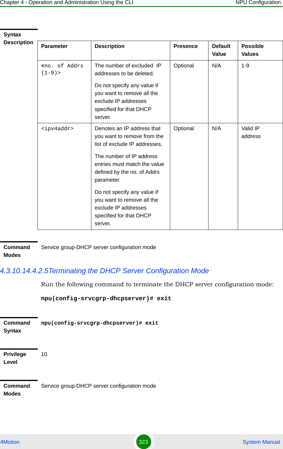
![Chapter 4 - Operation and Administration Using the CLI NPU Configuration4Motion 324 System Manual4.3.10.14.4.3 Configuring the DHCP ProxyAfter enabling the service group operation mode for the DHCP proxy, you can execute the following tasks:“Specifying DHCP Proxy Configuration Parameters” on page 324“Restoring the Default Configuration Parameters for the DHCP Proxy” on page 327“Terminating the DHCP Proxy Configuration Mode” on page 3274.3.10.14.4.3.1Specifying DHCP Proxy Configuration ParametersRun the following command to configure the DHCP proxy:npu(config-srvcgrp-dhcpproxy)# config ([offerreuse-holdtime <integer>] [lease-interval <integer>] [dnssrvr-addr <string>] [pool-subnet <string>] [dflt-gwaddr <string>] [renew-interval <integer>] [rebind-interval <integer>] [opt60 <string(30)>] [opt43 {[Name <string(64)>] [Value <string(64)>]}] [Sname <string(64)>] [File <string(128)>])IMPORTANTAn error may occur if you provide an invalid value for any of these parameters. Refer the syntax description for more information about the appropriate values and format for configuring these parameters.Command Syntaxnpu(config-srvcgrp-dhcpproxy)# config ([offerreuse-holdtime <integer>] [lease-interval <integer>] [dnssrvr-addr <string>] [pool-subnet <string>] [dflt-gwaddr <string>] [renew-interval <integer>] [rebind-interval <integer>] [opt60 <string(30)>] [opt43 {[Name <string(64)>] [Value <string(64)>]}] [Sname <string(64)>] [File <string(128)>])Privilege Level10](https://usermanual.wiki/Alvarion-Technologies/BMAX-OR-25.Manual-2/User-Guide-1114030-Page-228.png)
![Chapter 4 - Operation and Administration Using the CLI NPU Configuration4Motion 325 System ManualSyntax Description Parameter Description Presence Default ValuePossible Values[offerreuse-holdtime <integer>] Denotes the duration in seconds within which the MS should send a DHCP request to accept the address sent by the NPU.If the MS does not accept the address within this period, the MS is deregistered.Optional 5 0-120[lease-interval <integer>]Lease time in seconds of IP address allocated for MS from this Service Group. In the Proxy mode, this value is used if appropriate parameter is not received in RADIUS Access-Accept.Optional 86400 24 - 4294967295[dnssrvr-addr <string>]IP Address of the first DNS Server to be provisioned to MS from this Group. In the Proxy mode, this value is used if appropriate parameter is not received in RADIUS Access-AcceptOptional 0.0.0.0 Valid IP Address[pool-subnet <string>]The IP subnet mask to be provided by local DHCP Service with IP address for MSs from this Service Group. In the Proxy mode, this value is used if appropriate parameter is not received in RADIUS Access-Accept.Optional 255.255.255.255IP subnet[dflt-gwaddr <string>]IP address of Default Gateway to be provided by local DHCP Service with IP address for MS from this Service Group. In theProxy mode, this value is used if appropriate parameter is not received in RADIUS Access-Accept.Optional 0.0.0.0 Valid IP Address](https://usermanual.wiki/Alvarion-Technologies/BMAX-OR-25.Manual-2/User-Guide-1114030-Page-229.png)
![Chapter 4 - Operation and Administration Using the CLI NPU Configuration4Motion 326 System Manual[renew-interval <integer>]Denotes the period, after which, the MS can request for renewal of the lease which has expired. Specify the value of this parameter as a percentage of the lease-interval parameter.This value is used if appropriate parameter is not received in RADIUS Access-Accept.Optional 50 1-100[rebind-interval <integer>]Denotes the rebind interval maintained as a percentage of the lease interval. This is passed to the MS (DHCP client).This value is used if appropriate parameter is not received in RADIUS Access-Accept.Optional 75 1-99[opt60 <string(30)>]Configures option 60. Optional <dslforum.org>String (up to 30 characters)[opt43 {[Name <string(64)>]Configures option 43 Name Optional InternetGatewayDevice.ManagementServer.URLString (up to 64 characters)[Value <string(64)>]Configures option 43 Value Optional empty stringString (up to 64 characters)[Sname <string(64)>]Configures the proxy host name. This parameter is sent in dhcp-offer / dhcp-ack messages and may be used by certain CPEs.Optional empty stringString (up to 64 characters)[File <string(128)>]Configures the boot file name. This parameter is sent in dhcp-offer / dhcp-ack messages and may be used by certain CPEs.Optional empty stringString (up to 128 characters)](https://usermanual.wiki/Alvarion-Technologies/BMAX-OR-25.Manual-2/User-Guide-1114030-Page-230.png)
![Chapter 4 - Operation and Administration Using the CLI NPU Configuration4Motion 327 System Manual4.3.10.14.4.3.2Restoring the Default Configuration Parameters for the DHCP ProxyRun the following command to restore the default values of one or several DHCP proxy parameters. This command can also be used to delete the configured DNS server address (if specified).npu(config-srvcgrp-dhcpproxy)# no [offerreuse-holdtime] [lease-interval] [dnssrvr-addr][renew-interval] [rebind-interval]Specify one or several parameters to restore the specified parameters to their default values. Do not specify any parameter to restore all of these parameters to their default values.4.3.10.14.4.3.3Terminating the DHCP Proxy Configuration ModeRun the following command to terminate the DHCP proxy configuration mode: npu(config-srvcgrp-dhcpproxy)# exitCommand ModesService group-DHCP proxy configuration modeNOTERefer Section 4.3.10.14.4.3.1 for a description and default values of these parameters. Command Syntaxnpu(config-srvcgrp-dhcpproxy)# no [offerreuse-holdtime] [lease-interval] [dnssrvr-addr][renew-interval] [rebind-interval]Privilege Level10Command ModesService group-DHCP proxy configuration modeCommand Syntaxnpu(config-srvcgrp-dhcpproxy)# exitPrivilege Level10](https://usermanual.wiki/Alvarion-Technologies/BMAX-OR-25.Manual-2/User-Guide-1114030-Page-231.png)
![Chapter 4 - Operation and Administration Using the CLI NPU Configuration4Motion 328 System Manual4.3.10.14.4.4 Configuring the DHCP RelayAfter enabling the service group operation mode for the DHCP relay, you can execute any of the following tasks:“Configuring the DHCP Relay Parameters” on page 328“Terminating the DHCP Relay Configuration Mode” on page 3324.3.10.14.4.4.1Configuring the DHCP Relay ParametersRun the following command to configure the DHCP server address for the DHCP relay:npu(config-srvcgrp-dhcprelay)# config ([server-addr <ipV4Addr>] [{EnableOpt82|DisableOpt82}])Command ModesService group-DHCP proxy configuration modeIMPORTANTAn error may occur if you provide an invalid value for the DHCP server address. Refer the syntax description for more information about the appropriate values and format for configuring this parameters.Command Syntaxnpu(config-srvcgrp-dhcprelay)# config ([server-addr <ipV4Addr>] [{EnableOpt82|DisableOpt82}])Privilege Level10Syntax Description Parameter Description Presence Default ValuePossible Values[server-addr <ipv4addr>]Denotes the IP address of the external DHCP server,Mandatory N/A Valid IP Address[{EnableOpt82|DisableOpt82}]Denotes whether DHCP option 82 is enabled or disabled.Optional DisableOpt82EnableOpt82DisableOpt82](https://usermanual.wiki/Alvarion-Technologies/BMAX-OR-25.Manual-2/User-Guide-1114030-Page-232.png)
![Chapter 4 - Operation and Administration Using the CLI NPU Configuration4Motion 329 System Manual4.3.10.14.4.4.2Configuring the DHCP Relay Option 82 ParametersIf Option 82 for the DHCP Relay is enabled, run the following command to configure suboptions of option 82 of DHCP messages:npu(config-srvcgrp-dhcprelay-Opt82)# config ([Subopt1value {Default|MSID|BSID|NASID|NASIP|Full-NAI|Domain|AsciiFrStrng <string(32)>|BinFrStrng <string(32)>}] [Subopt2value {Default|MSID|BSID|NASID|NASIP|Full-NAI|Domain|AsciiFrStrng <string(32)>|BinFrStrng <string(32)>}] [Subopt6value {Default|MSID|BSID|NASID|NASIP|Full-NAI|Domain|AsciiFrStrng <string(32)>|BinFrStrng <string(32)>}] [{Subopt7value [service-type] [vendor-specific] [session-timeout]}] [{EnableUnicast|DisableUnicast}])Command ModesService group-DHCP relay configuration modeIMPORTANTFor DhcpRlOpt82SubOpt1BinFrstrng value, enter hex string without spaces. If Opt82Unicast is enabled then DHCP relay agent appends option 82 to all DHCP messages (unicast and broadcast). If Opt82Unicast is disabled (default) then DHCP relay agent appends option 82 only to broadcast DHCP request messages.Command Syntaxnpu(config-srvcgrp-dhcprelay-Opt82)# config ([Subopt1value {Default|MSID|BSID|NASID|NASIP|Full-NAI|Domain|AsciiFrStrng <string(32)>|BinFrStrng <string(32)>}] [Subopt2value {Default|MSID|BSID|NASID|NASIP|Full-NAI|Domain|AsciiFrStrng <string(32)>|BinFrStrng <string(32)>}] [Subopt6value {Default|MSID|BSID|NASID|NASIP|Full-NAI|Domain|AsciiFrStrng <string(32)>|BinFrStrng <string(32)>}] [{Subopt7value [service-type] [vendor-specific] [session-timeout]}] [{EnableUnicast|DisableUnicast}])Privilege Level10](https://usermanual.wiki/Alvarion-Technologies/BMAX-OR-25.Manual-2/User-Guide-1114030-Page-233.png)
![Chapter 4 - Operation and Administration Using the CLI NPU Configuration4Motion 330 System ManualSyntax Description Parameter Description Presence Default ValuePossible Values[Subopt1value {Default|MSID|BSID|NASID|NASIP|Full-NAI|Domain|AsciiFrStrng <string(32)>|BinFrStrng <string(32)>}]Configures the suboption 1 (Agent Circuit ID) of DHCP option 82.For AsciiFrStrng (string enter up to 32 characters,For BinFrStrng (string enter a string of up to 32 hexadecimal digits (no spaces).Optional Not Set DefaultMSIDBSIDNASIDNASIPFull-NAI Domain AsciiFrStrng (string32)BinFrStrng (string32)[Subopt2value {Default|MSID|BSID|NASID|NASIP|Full-NAI|Domain|AsciiFrStrng <string(32)>|BinFrStrng <string(32)>}Configures the suboption 2 (Agent Remote ID) of DHCP option 82. For AsciiFrStrng (string enter up to 32 characters,For BinFrStrng (string enter a string of up to 32 hexadecimal digits (no spaces).Optional Not Set DefaultMSIDBSIDNASIDNASIPFull-NAI Domain AsciiFrStrng (string32)BinFrStrng (string32)](https://usermanual.wiki/Alvarion-Technologies/BMAX-OR-25.Manual-2/User-Guide-1114030-Page-234.png)
![Chapter 4 - Operation and Administration Using the CLI NPU Configuration4Motion 331 System Manual[Subopt6value {Default|MSID|BSID|NASID|NASIP|Full-NAI|Domain|AsciiFrStrng <string(32)>|BinFrStrng <string(32)>}] Configures the suboption 6 (Agent Subscriber ID )of DHCP option 82.For AsciiFrStrng (string enter up to 32 characters,For BinFrStrng (string enter a string of up to 32 hexadecimal digits (no spaces).Optional Not Set DefaultMSIDBSIDNASIDNASIPFull-NAI Domain AsciiFrStrng (string32)BinFrStrng (string32)[{Subopt7value [service-type] [vendor-specific] [session-timeout]}]Configures the suboption 7 of DHCP option 82.Allows enabling/disabling the use of suboption 7 by specifying it. In addition, allows enabling/disabling the following attributes (by specifying attributes to be enabled) if suboption 7 is enabled:service-type (attribute 6)vendor-specific (attribute 26)session-timeout (attribute 27)Optional[{EnableUnicast|DisableUnicast}])Indicates whether the Unicast parameter is enabled or disabled.Optional Disable EnableDisableCommand ModeService group-DHCP relay-option 82 configuration mode](https://usermanual.wiki/Alvarion-Technologies/BMAX-OR-25.Manual-2/User-Guide-1114030-Page-235.png)
![Chapter 4 - Operation and Administration Using the CLI NPU Configuration4Motion 332 System Manual4.3.10.14.4.4.3Removing the DHCP Relay suboption valuesRun the following command to remove one, several or all of the Suboption values configured by the user for DHCP Option 82.npu(config-srvcgrp-dhcprelay-opt82)# no [Subopt1value] [Subopt2value] [Subopt6value] [Subopt7value]4.3.10.14.4.4.4Terminating the DHCP Relay Configuration ModeRun the following command to terminate the DHCP relay configuration mode for this service group: npu(config-srvcgrp-dhcprelay)# exitCommand Syntaxnpu(config-srvcgrp-dhcprelay-opt82)# no [Subopt1value] [Subopt2value] [Subopt6value] [Subopt7value]Privilage Level10Syntax Description Parameter Description Presence Default ValuePossible Valuesno [Subopt1value] [Subopt2value] [Subopt6value] [Subopt7value]Indicates the removal status of DHCP Option 82 suboptions.If no suboption is specified, the values of all suboptions will be removed.Optional N/A N/ACommand ModeService group-DHCP relay-Option 82 configuration modeCommand Syntaxnpu(config-srvcgrp-dhcprelay)# exitPrivilege Level10](https://usermanual.wiki/Alvarion-Technologies/BMAX-OR-25.Manual-2/User-Guide-1114030-Page-236.png)
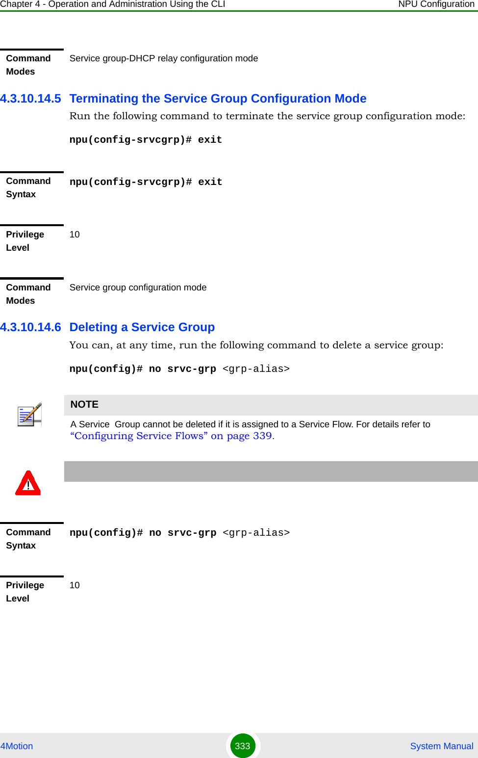
![Chapter 4 - Operation and Administration Using the CLI NPU Configuration4Motion 334 System Manual4.3.10.14.7 Displaying Configuration Information for the Service Group To display configuration information for one service group or for all service groups, run the following command:npu# show srvc-grp [<grp-alias>]Syntax Description Parameter Description Presence Default ValuePossible Values<grp-alias> Denotes the group-alias for which the service group to be deleted. Mandatory N/A StringCommand ModesGlobal configuration modeCommand Syntaxnpu# show srvc-grp [<grp-alias>]Privilege Level1Syntax Description Parameter Description Presence Default ValuePossible Values[<grp-alias>] Denotes the group-alias for which the service group to be displayed. If no grp-alias is specified, the parameters of all service groups will be displayed.Optional N/A StringDisplay FormatAccording to configured DHCP mode and other parameters.](https://usermanual.wiki/Alvarion-Technologies/BMAX-OR-25.Manual-2/User-Guide-1114030-Page-238.png)
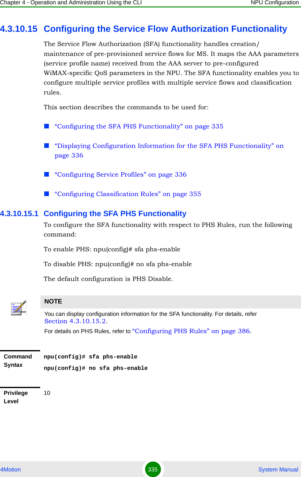
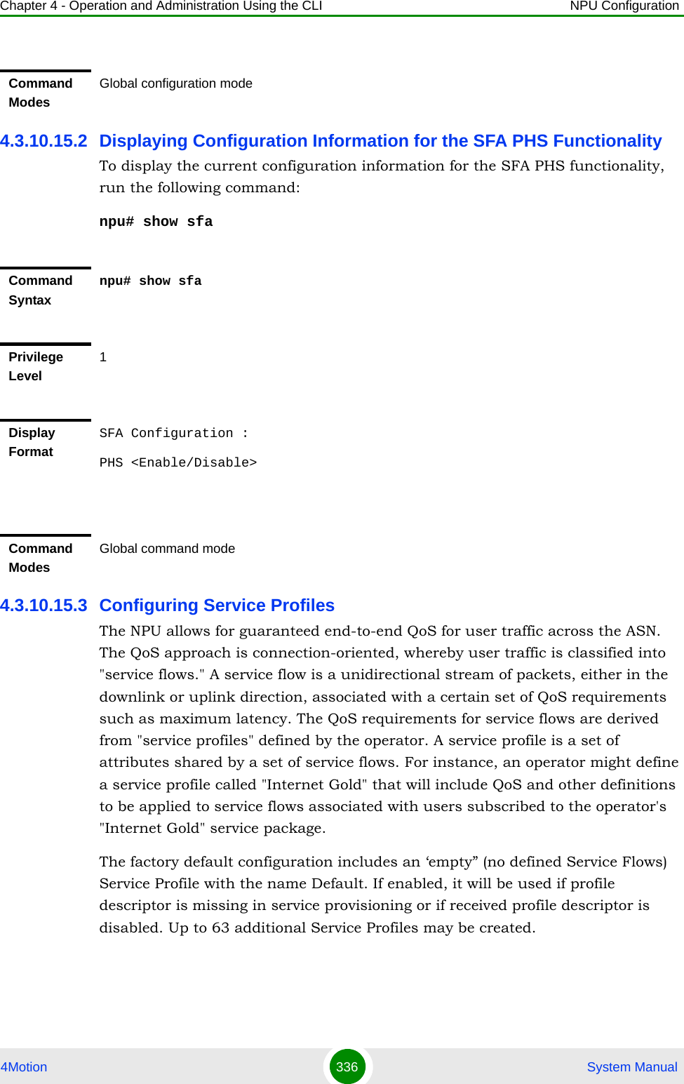
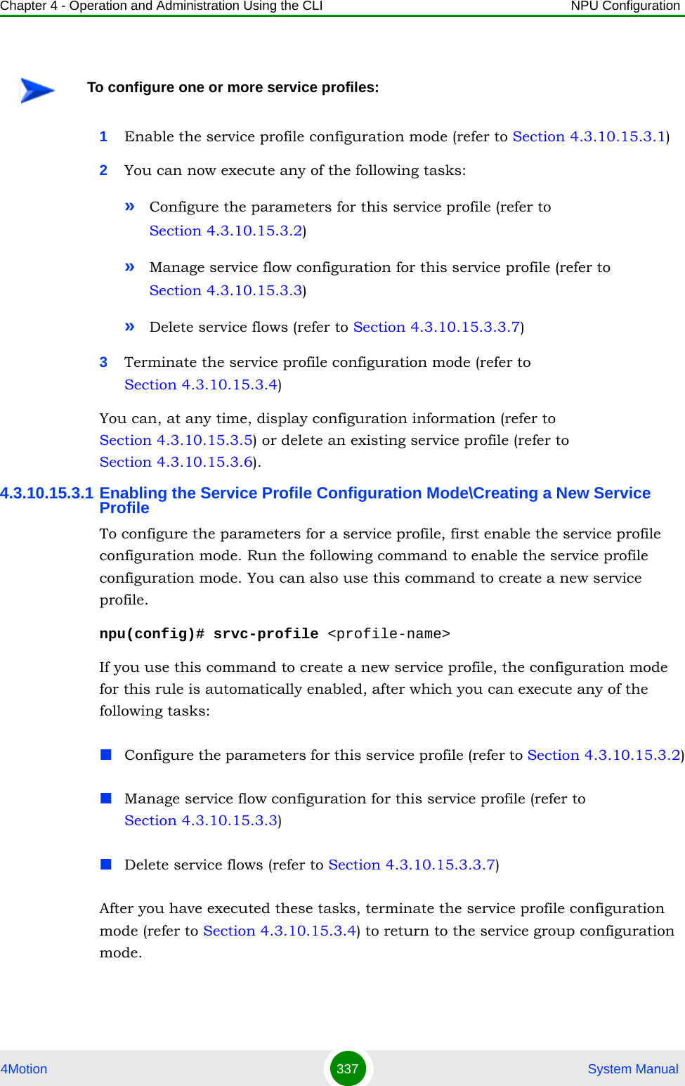
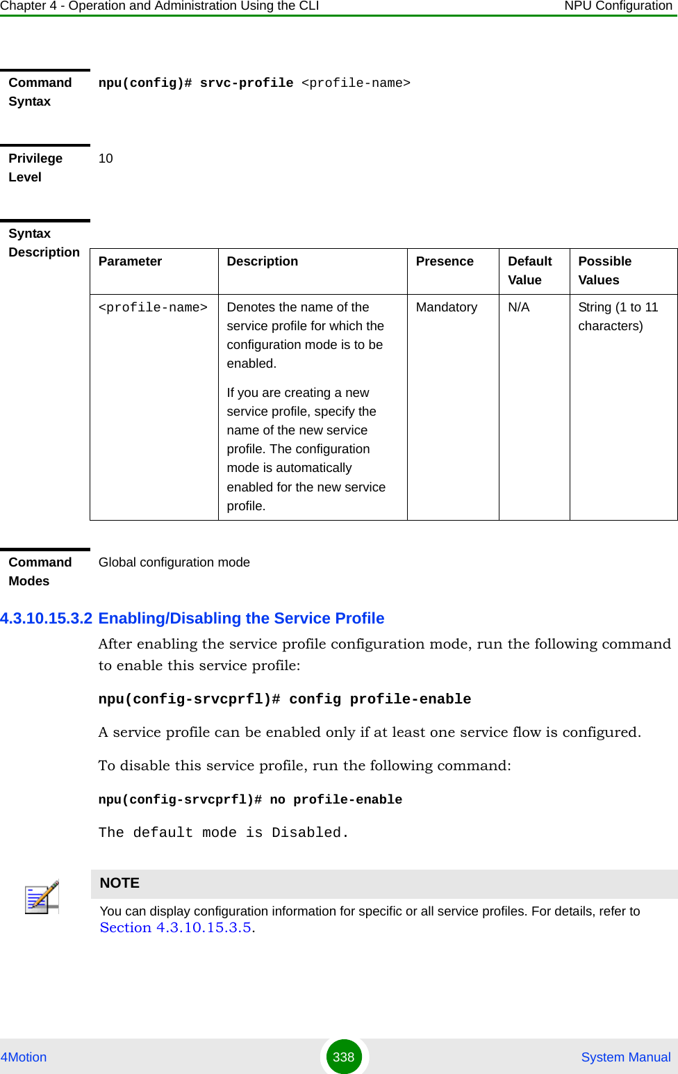
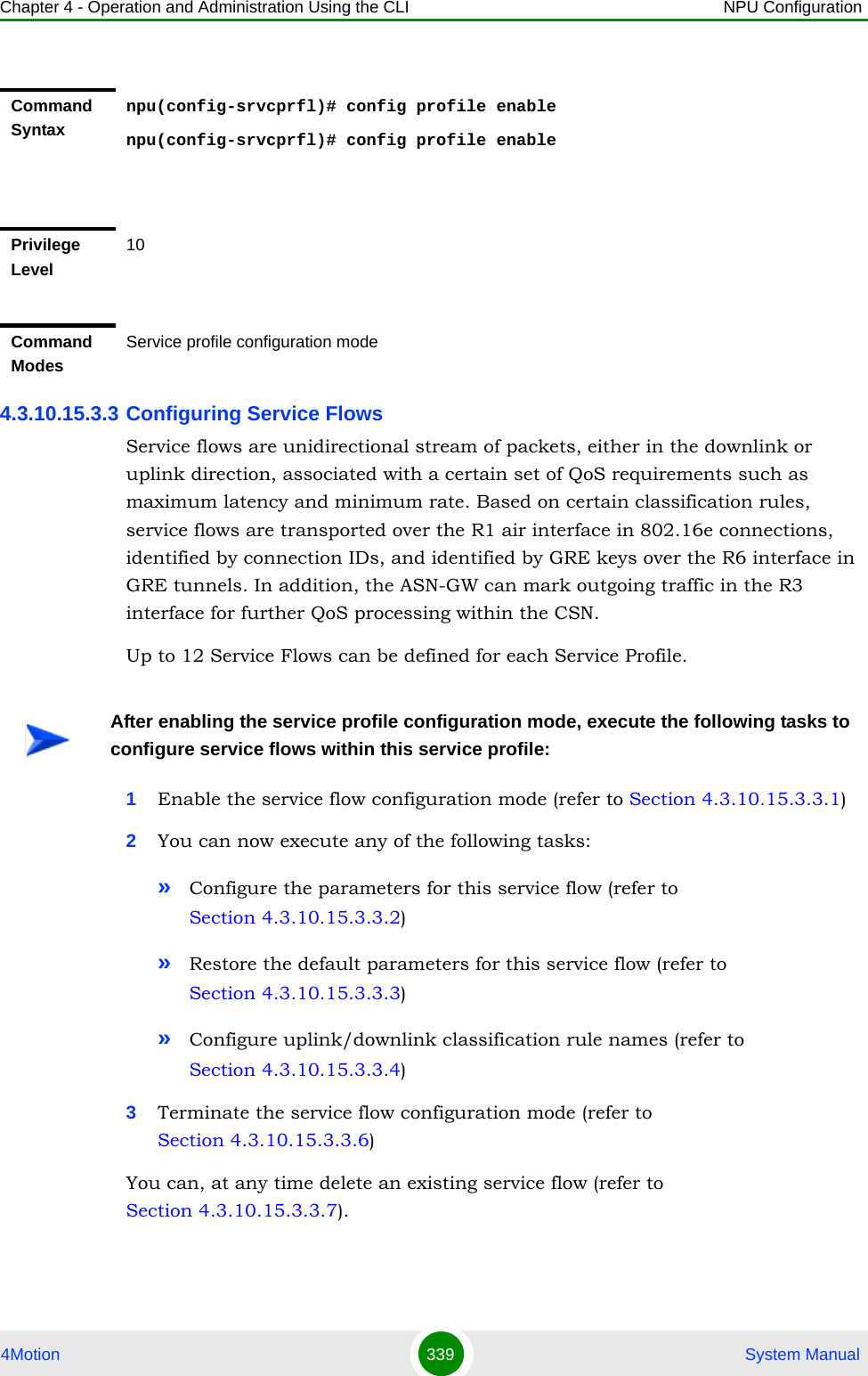
![Chapter 4 - Operation and Administration Using the CLI NPU Configuration4Motion 340 System Manual4.3.10.15.3.3.1Enabling the Service Flow Configuration Mode\ Creating a New Service FlowTo configure the parameters for a service flow, first enable the service flow configuration mode. Run the following command to enable the service flow configuration mode. You can also use this command to create a new service flow.npu(config-srvcprfl)# flow [<flow-id (1-255)] [ServiceGrpAlias <srvc-grp-alias>] [ServiceIfAlias <string>]If you use this command to create a new service flow, the configuration mode for this service flow is automatically enabled, after which you can execute any of the following tasks:Configure the parameters for this service flow (refer to Section 4.3.10.15.3.3.2)Restore the default parameters for this service flow (refer to Section 4.3.10.15.3.3.3)Configure uplink/downlink classification rule names (refer to Section 4.3.10.15.3.3.4)After you have executed these tasks, you can terminate the service flow configuration mode, and return to the service profile configuration mode (refer to Section 4.3.10.15.3.3.6).Command Syntaxnpu(config-srvcprfl)#flow [<flow-id (1-255)] [ServiceGrpAlias <srvc-grp-alias>] [ServiceIfAlias <string>]Privilege Level10](https://usermanual.wiki/Alvarion-Technologies/BMAX-OR-25.Manual-2/User-Guide-1114030-Page-244.png)
![Chapter 4 - Operation and Administration Using the CLI NPU Configuration4Motion 341 System Manual4.3.10.15.3.3.2Specifying Service Flow Configuration ParametersAfter enabling the service flow configuration mode, run the following command to configure the parameters for this service flow:npu(config-srvcprfl-flow)# config ([flow-type <type (1)>] [cs-type <type (1 | 4)>] [media-type <string>] [uldatadlvry-type <type(0<UGS> | 1<RTVR> | 2<NRTVR> | 3<BE> | 4<ERTVR> | 255<ANY>)>] Syntax Description Parameter Description Presence Default ValuePossible Valuesflow [<flow-id (1-255)]Denotes the flow ID of the service flow for which the service flow configuration mode is to be enabled. If you are creating a new service flow, specify the service flow ID of the new service flow. The configuration mode is automatically enabled for the new service flow. Mandatory N/A 1-255[ServiceGrpAlias <srvc-grp-alias>]Indicates the Reference Name for an existing service group to be used by the service flow. VPWS-QinQ and VPWS Transparent Service Groups are applicable only for Service Flows of the Default Service Profile.Mandatory when creating a new flowN/A An existing Service Group Alias.[ServiceIfAlias <string>]Indicates the Reference Name for an existing QinQ service interface.Applicable only if the assigned Service Group is of type VPWS-QinQ (in a VLANCS Service Flow of the Default Service Profile).Mandatory when creating a new flow, only if the type of the specified ServiceGrpAlias is VPWS-QinQ.N/A An existing QinQ Service Interface.Command ModesService profile configuration mode](https://usermanual.wiki/Alvarion-Technologies/BMAX-OR-25.Manual-2/User-Guide-1114030-Page-245.png)
![Chapter 4 - Operation and Administration Using the CLI NPU Configuration4Motion 342 System Manual[ulqos-maxsustainedrate <value(10000-10000000)>] [ulqos-trafficpriority <value(0-7)>] [dldatadlvry-type <type(0<UGS> | 1<RTVR> | 2<NRTVR> | 3<BE> | 4<ERTVR> | 255<ANY>)>] [dlqos-maxsustainedrate <value(10000-10000000)>] [dlqos-trafficpriority <value(0-7)>] [ulSfQosMinReservedRate <integer>] [ulSfQosMaxLatency <integer>] [ulSfQosToleratedJitter <integer)>] [ulSfQosUnsolicitedGrantInterval <integer(0-65535)>] [ulSfQosSduSize <integer(0-255)>] [dlSfQosMinReservedRate <integer>] [dlSfQosMaxLatency <integer>] [dlSfQosToleratedJitter <integer>] [dlSfQosSduSize <integer(0-255)>])IMPORTANTAn error may occur if you provide an invalid value for any of these parameters. Refer the syntax description for more information about the appropriate values and format for configuring these parameters.Command Syntaxnpu(config-srvcprfl-flow)# config ([flow-type <type (1)>] [cs-type <type (1 | 4)>] [media-type <string>] [uldatadlvry-type <type(0<UGS> | 1<RTVR> | 2<NRTVR> | 3<BE> | 4<ERTVR> | 255<ANY>)>] [ulqos-maxsustainedrate <value(10000-10000000)>] [ulqos-trafficpriority <value(0-7)>] [dldatadlvry-type <type(0<UGS> | 1<RTVR> | 2<NRTVR> | 3<BE> | 4<ERTVR> | 255<ANY>)>] [dlqos-maxsustainedrate <value(10000-10000000)>] [dlqos-trafficpriority <value(0-7)>] [ulSfQosMinReservedRate <integer>] [ulSfQosMaxLatency <integer>] [ulSfQosToleratedJitter <integer)>] [ulSfQosUnsolicitedGrantInterval <integer(0-65535)>] [ulSfQosSduSize <integer(0-255)>] [dlSfQosMinReservedRate <integer>] [dlSfQosMaxLatency <integer>] [dlSfQosToleratedJitter <integer>] [dlSfQosSduSize <integer(0-255)>])Privilege Level10Syntax Description Parameter Description Presence Default ValuePossible Values[flow-type <type (1)>] Denotes the type of flow, that is, bi-directional (1) or multicast (2).multicast (2) is not supported in current release.Optional 1 1: Indicates bi-directional](https://usermanual.wiki/Alvarion-Technologies/BMAX-OR-25.Manual-2/User-Guide-1114030-Page-246.png)
![Chapter 4 - Operation and Administration Using the CLI NPU Configuration4Motion 343 System Manual[cs-type <type (1 | 4)>]Convergence Sublayer Type. This parameter is applied to both UL and DL Service Flows.Must match the type of service group referenced by ServiceGrpAlias during creation of the flow: IPv4CS should be selected if the assigned Service Group is .of type IP. VLANCS should be selected if the assigned Service Group is either VPWS-Transparent or VPWS-QinQ.Optional 1 (IPv4CS)1: IPv4CS. 4: VLANCS [media-type <string>]Describes the type of media carried by the service flow.Optional Null String, up to 32 characters[uldatadlvry-type <type(0<UGS> | 1<RTVR> | 2<NRTVR> | 3<BE> | 4<ERTVR> | 255<ANY>)>]Denotes the data delivery type for uplink traffic carried by the service flow. Optional 3 (BE) 0-4 or 255 for ANY.[ulqos-maxsustainedrate <value(10000-10000000)>]Denotes the maximum sustained traffic rate, in bps, for uplink traffic carried by the service flow.Although available for all service flows, applicable only for service flows with the appropriate uplink data delivery type (NRTVR, RTVR, BE, ERTVR, ANY)Optional 250000 10000-10000000 bps[ulqos-trafficpriority <value(0-7)>]Denotes the traffic priority to be applied to the uplink traffic carried by the service flow.Optional 0 0-7, where 0 is lowest and 7 is highest](https://usermanual.wiki/Alvarion-Technologies/BMAX-OR-25.Manual-2/User-Guide-1114030-Page-247.png)
![Chapter 4 - Operation and Administration Using the CLI NPU Configuration4Motion 344 System Manual[dldatadlvry-type <type(0<UGS> | 1<RTVR> | 2<NRTVR> | 3<BE> | 4<ERTVR> | 255<ANY>)>]Denotes the data delivery type for the downlink traffic carried by the service flow. Optional 3 (BE) 0-4 or 255 for ANY.[dlqos-maxsustainedrate <value(10000-10000000)>]Denotes the maximum sustained traffic rate, in bps, for the downlink traffic carried by the service flow.Although available for all service flows, applicable only for service flows with the appropriate downlink data delivery type (NRTVR, RTVR, BE, ERTVR, ANY)Optional 250000 10000-10000000 bps[dlqos-trafficpriority <value(0-7)>]Denotes the traffic priority to be applied to the downlink traffic carried by the service flow.Optional 0 0-7, where 7 is highest[ulSfQosMinReservedRate <integer>]tthe minimum rate in bps reserved for this uplink service flow.Although available for all service flows, applicable only for service flows with the appropriate uplink data delivery type (UGS, NRTVR, RTVR, ERTVR).For NRTVER, RTVR and ERTVR-cannot be higher than ulqos-maxsustainedrate.Optional 250000 0- 10000000](https://usermanual.wiki/Alvarion-Technologies/BMAX-OR-25.Manual-2/User-Guide-1114030-Page-248.png)
![Chapter 4 - Operation and Administration Using the CLI NPU Configuration4Motion 345 System Manual[ulSfQosMaxLatency <integer>]The maximum latency in ms allowed in the uplink.Although available for all service flows, applicable only for service flows with the appropriate uplink data delivery type (UGS, RTVR, ERTVR).If uplink data delivery type is ERTVR or UGS,the default value should be 90ms.Optional 500 0- 4294967295[ulSfQosToleratedJitter <integer)>]the maximum delay variation (jitter) in milliseconds for this uplink service flow.Although available for all service flows, applicable only for service flows with the appropriate uplink data delivery type (UGS, ERTVR)Optional 0 0- 4294967295[ulSfQosUnsolicitedGrantInterval <integer(0-65535)>]The nominal interval in ms between successive data grant opportunities for this uplink service flow.Although available for all service flows, applicable only for service flows with the appropriate uplink data delivery type (UGS, RTVR, ERTVR).Must be lower than ulSfQosMaxLatency.Optional 20 0-65535[ulSfQosSduSize <integer(0-255)>]Represents the number of bytes in the fixed size SDU. This parameter may be used for a UGS service flow when the length of IP packets on the data plane is fixed and known in advance.Although available for all service flows, applicable only for service flows with the appropriate uplink data delivery type (UGS).Optional 49 0-255](https://usermanual.wiki/Alvarion-Technologies/BMAX-OR-25.Manual-2/User-Guide-1114030-Page-249.png)
![Chapter 4 - Operation and Administration Using the CLI NPU Configuration4Motion 346 System Manual[dlSfQosMinReservedRate <integer>]tthe minimum rate in bps reserved for this downlink service flow.Although available for all service flows, applicable only for service flows with the appropriate downlink data delivery type (UGS, NRTVR, RTVR, ERTVR)For NRTVER, RTVR and ERTVR-cannot be higher than dlqos-maxsustainedrate.Optional 250000 0- 10000000[dlSfQosMaxLatency <integer>]The maximum latency in ms allowed in the downlink.Although available for all service flows, applicable only for service flows with the appropriate downlink data delivery type (UGS, RTVR, ERTVR).If uplink data delivery type is ERTVR or UGS,the default value should be 90ms.Optional 500 0- 4294967295[dlSfQosToleratedJitter <integer)>]the maximum delay variation (jitter) in milliseconds for this downlink service flow.Although available for all service flows, applicable only for service flows with the appropriate downlink data delivery type (UGS, ERTVR)Optional 0 0- 4294967295[dlSfQosSduSize <integer(0-255)>]Represents the number of bytes in the fixed size SDU. This parameter may be used for a UGS service flow when the length of IP packets on the data plane is fixed and known in advance.Although available for all service flows, applicable only for service flows with the appropriate downlink data delivery type (UGS).Optional 49 0-255](https://usermanual.wiki/Alvarion-Technologies/BMAX-OR-25.Manual-2/User-Guide-1114030-Page-250.png)
![Chapter 4 - Operation and Administration Using the CLI NPU Configuration4Motion 347 System Manual4.3.10.15.3.3.3Restoring the Default Service Flow Configuration ParametersRun the following command to restore the default values of one or several parameters for this service flow:npu(config-srvcprfl-flow)# no [cs-type] [media-type] [uldatadlvry-type] [ulqos-maxsustainedrate] [ulqos-trafficpriority] [dldatadlvry-type] [dlqos-maxsustainedrate] [dlqos-trafficpriority][ulSfQosMinReservedRate] [ulSfQosMaxLatency] [ulSfQosToleratedJitter] [ulSfQosUnsolicitedGrantInterval] [ulSfQosSduSize] [dlSfQosMinReservedRate] [dlSfQosMaxLatency] [dlSfQosToleratedJitter] [dlSfQosSduSize]Do not specify ant parameter to restore all parameters to their default values.Command ModesService profile-service flow configuration modeNOTERefer to Section 4.3.10.15.3.3.2 for a description and default values of these parameters. Command Syntaxnpu(config-srvcprfl-flow)# no [cs-type] [media-type] [uldatadlvry-type] [ulqos-maxsustainedrate] [ulqos-trafficpriority] [dldatadlvry-type] [dlqos-maxsustainedrate] [dlqos-trafficpriority][ulSfQosMinReservedRate] [ulSfQosMaxLatency] [ulSfQosToleratedJitter] [ulSfQosUnsolicitedGrantInterval] [ulSfQosSduSize] [dlSfQosMinReservedRate] [dlSfQosMaxLatency] [dlSfQosToleratedJitter] [dlSfQosSduSize]Privilege Level10Command ModesService profile-service flow configuration mode](https://usermanual.wiki/Alvarion-Technologies/BMAX-OR-25.Manual-2/User-Guide-1114030-Page-251.png)
![Chapter 4 - Operation and Administration Using the CLI NPU Configuration4Motion 348 System Manual4.3.10.15.3.3.4Configuring Uplink/Downlink Classification Rule NamesAfter enabling the service flow configuration mode, run the following commands to configure up to a maximum of 6 uplink and 6 downlink classification rules:npu(config-srvcprfl-flow)# ulclsf-rulename <num_of_rule_names (1-6)> <rulename> [<rulename>] [...]npu(config-srvcprfl-flow)# dlclsf-rulename <num_of_rule_names (1-6)> <rulename> [<rulename>] [...]After you have executed these tasks, you can terminate the service flow configuration mode, and return to the service profile configuration mode (Section 4.3.10.15.3.3.6). For more information about configuring classification rules, refer “Configuring Classification Rules” on page 355.Command Syntaxnpu(config-srvcprfl-flow)# ulclsf-rulename <num_of_rule_names (1-6)> <rulename> [<rulename>] [...]npu(config-srvcprfl-flow)# dlclsf-rulename <num_of_rule_names (1-6)> <rulename> [<rulename>] [...]Privilege Level10Syntax Description Parameter Description Presence Default ValuePossible Values<num_of_rule_names (1-6)>Indicates the number of uplink/downlink classification rules to be createdMandatory N/A 1-6](https://usermanual.wiki/Alvarion-Technologies/BMAX-OR-25.Manual-2/User-Guide-1114030-Page-252.png)
![Chapter 4 - Operation and Administration Using the CLI NPU Configuration4Motion 349 System Manual4.3.10.15.3.3.5Deleting Uplink/Downlink Classification Rule NamesAfter enabling the service flow configuration mode, run the following commands to delete uplink/downlink classification rules:npu(config-srvcprfl-flow)# no ulclsf-rulename [<num_of_rulenames (1-6)> <rulename> [<rulename>] ...]npu(config-srvcprfl-flow)# no dlclsf-rulename [<num_of_rulenames (1-6)> <rulename> [<rulename>] ...]After you have executed these commands, you can terminate the service flow configuration mode, and return to the service profile configuration mode (refer to Section 4.3.10.15.3.3.6)<rulename> Indicates the name of the uplink/downlink classification rule to be linked to this service flow. Use the classification rule name to reference the appropriate classification rule.For VLANCS service flows the linked uplink and downlink classification rules should be the same. This is because the VLANCS classificaion rules define the CVID (Customer VLAN ID), that should be the same for uplink and downlink flows.The number of rule name entries must match the number defined in num_of_rule_names.For more information about creating classification rules, refer to Section 4.3.10.15.4.1.Mandatory N/A Valid classification rule nameCommand ModesService profile-service flow configuration mode](https://usermanual.wiki/Alvarion-Technologies/BMAX-OR-25.Manual-2/User-Guide-1114030-Page-253.png)
![Chapter 4 - Operation and Administration Using the CLI NPU Configuration4Motion 350 System Manual4.3.10.15.3.3.6Terminating the Service Flow Configuration ModeRun the following command to terminate the service flow configuration mode:npu(config-srvcprfl-flow)# exitCommand Syntaxnpu(config-srvcprfl-flow)# no ulclsf-rulename [<num_of_rulenames (1-6)> <rulename> [<rulename>] ...]npu(config-srvcprfl-flow)# no dlclsf-rulename [<num_of_rulenames (1-6)> <rulename> [<rulename>] ...]Privilege Level10Syntax Description Parameter Description Presence Default ValuePossible Values[<num_of_rulenames (1-6)>Indicates the number of uplink/downlink classification rules to be deleted.Mandatory N/A 1-6<rulename> Indicates the name of the uplink/downlink classification rule to be deleted from to this service flow. Use the classification rule name to reference the appropriate classification rule.The number of rule name entries must match the number defined in num_of_rule_names.Mandatory N/A Valid classification rule nameCommand ModesService profile-service flow configuration modeCommand Syntaxnpu(config-srvcprfl-flow)# exit](https://usermanual.wiki/Alvarion-Technologies/BMAX-OR-25.Manual-2/User-Guide-1114030-Page-254.png)
![Chapter 4 - Operation and Administration Using the CLI NPU Configuration4Motion 351 System Manual4.3.10.15.3.3.7Deleting Service FlowsYou can, at any time, run the following command to delete one or all service flows:npu(config-srvcprfl)# no flow [<flow-id>]4.3.10.15.3.4 Terminating the Service Profile Configuration ModeRun the following command to terminate the service profile configuration mode:Privilege Level10Command ModesService profile-service flow configuration modeCAUTIONSpecify the flow ID if you want to delete a specific service flow. Otherwise all the configured service flows are deleted.Command Syntaxnpu(config-srvcprfl)# no flow [<flow-id>]Privilege Level10Command Syntaxnpu(config-srvcprfl)# no flow [<flow-id>]Syntax Description Parameter Description Presence Default ValuePossible Values[<flow-id>] Denotes the flow ID of the service flow to be deleted. If you do nort specify a value for this parameter, all the service flows are deleted.Optional N/A 0-232Command ModesService profile configuration mode](https://usermanual.wiki/Alvarion-Technologies/BMAX-OR-25.Manual-2/User-Guide-1114030-Page-255.png)
![Chapter 4 - Operation and Administration Using the CLI NPU Configuration4Motion 352 System Manualnpu(config-srvcprfl)# exit4.3.10.15.3.5 Displaying Configuration Information for Service Profiles To display all or specific service profiles, run the following command:npu# show srvc-profile [<profile-name>]Specify the profile name if you want to display configuration information for a particular service profile. Do not specify a value for this parameter if you want to view configuration information for all service profile.Command Syntaxnpu(config-srvcprfl)# exitPrivilege Level10Command ModesService profile configuration modeIMPORTANTAn error may occur if you provide an invalid service profile name. Refer the syntax description for more information about the appropriate values and format for configuring this parameter.Command Syntaxnpu# show srvc-profile [<profile-name>]Privilege Level1](https://usermanual.wiki/Alvarion-Technologies/BMAX-OR-25.Manual-2/User-Guide-1114030-Page-256.png)
![Chapter 4 - Operation and Administration Using the CLI NPU Configuration4Motion 353 System ManualSyntax Description Parameter Description Presence Default ValuePossible Values[<profile-name>]Indicates the name of the service profile for which configuration information is to be displayed. If you do not specify a value for this parameter, configuration information is displayed for all service profiles.Optional N/A String](https://usermanual.wiki/Alvarion-Technologies/BMAX-OR-25.Manual-2/User-Guide-1114030-Page-257.png)
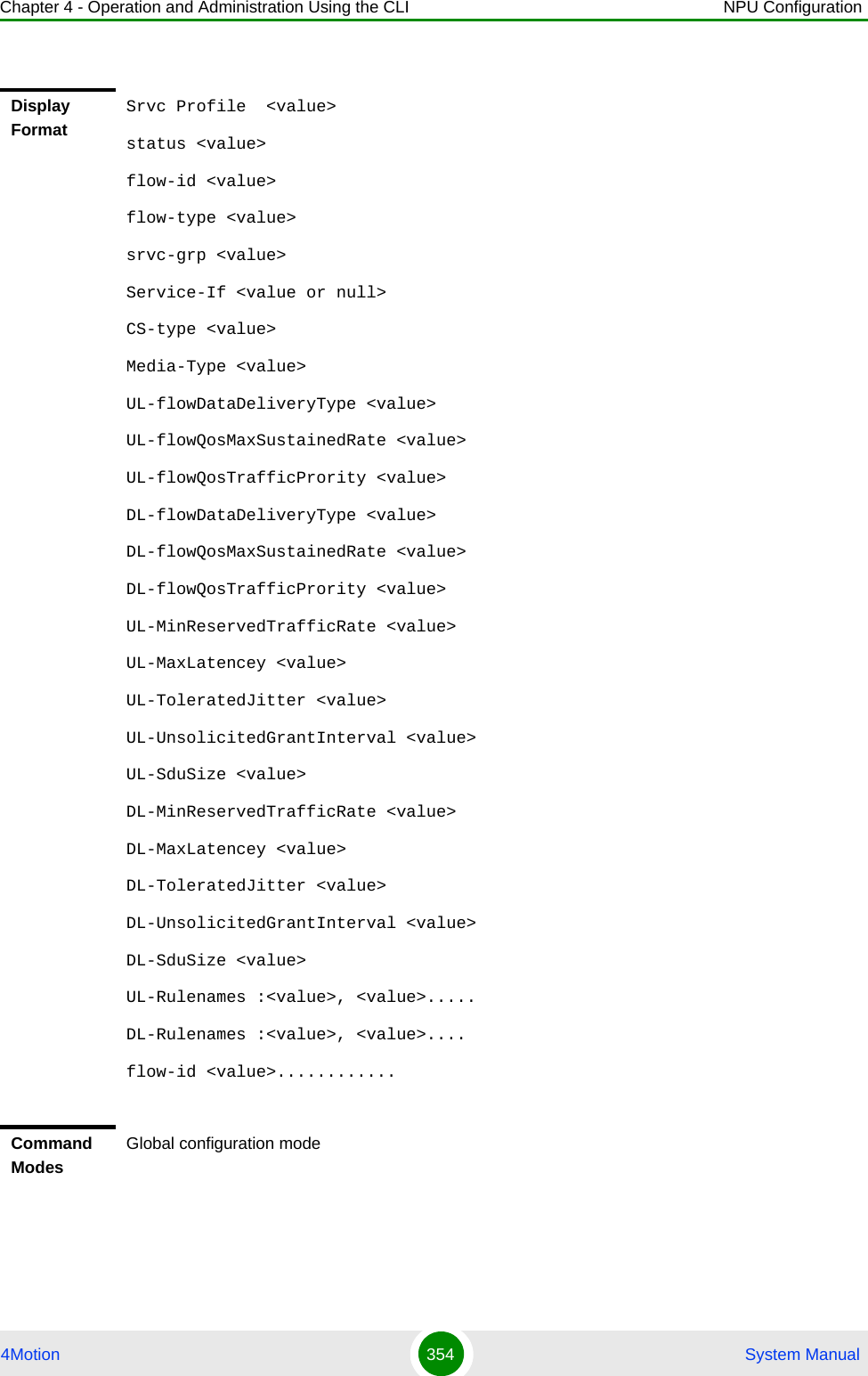
![Chapter 4 - Operation and Administration Using the CLI NPU Configuration4Motion 355 System Manual4.3.10.15.3.6 Deleting Service ProfilesRun the following command to delete one or all service profiles:npu(config)# no srvc-profile [<profile-name>]4.3.10.15.4 Configuring Classification RulesClassification rules are user-configurable rules that are used to classify packets transmitted on the bearer plane. You can associate one or more classification rules with a particular service profile (For details, refer to Section 4.3.10.15.3.3.4). You can define an L3 classification rule with respect to the following criteria:IP ToS/DSCPIP protocol (such as UDP or TCP)NOTEThe Default Service Profile cannot be deleted.CAUTIONSpecify the profile name if you want to delete a specific service profile. Otherwise all the configured service profiles (excluding the Default Service Profile) are deleted.Command Syntaxnpu(config)# no srvc-profile [<profile-name>]Privilege Level10Syntax Description Parameter Description Presence Default ValuePossible Values[<profile-name>]Denotes the name of the service profile you want to delete. Specify this parameter only if you want to delete a specific service profile.Optional N/A StringCommand ModesGlobal configuration mode](https://usermanual.wiki/Alvarion-Technologies/BMAX-OR-25.Manual-2/User-Guide-1114030-Page-259.png)
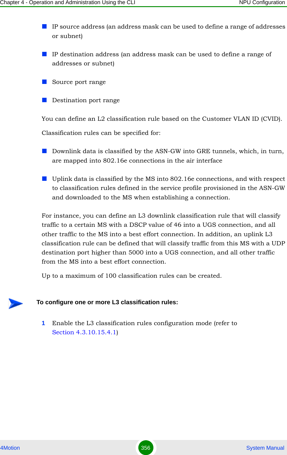
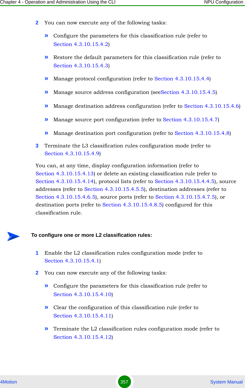
![Chapter 4 - Operation and Administration Using the CLI NPU Configuration4Motion 358 System ManualYou can, at any time, display configuration information (refer to Section 4.3.10.15.4.13) or delete an existing classification rule (refer to Section 4.3.10.15.4.14).4.3.10.15.4.1 Enabling the Classification Rule Configuration Mode\ Creating a New Classification RuleTo configure the parameters for a classification rule, first enable the classification rule configuration mode. Run the following command to enable the classification rule configuration mode. You can also use this command to create a new classification rule.npu(config)# clsf-rule <rulename> [clsfRuleType {L2 | L3}]If you use this command to create a new classification rule, the configuration mode for this rule is automatically enabled.After enabling the classification rule configuration mode for an L3 rule you can execute any of the following tasks:Configure the parameters for this classification rule (refer to Section 4.3.10.15.4.2).Restore the default parameters for this classification rule (refer to Section 4.3.10.15.4.3)Manage protocol configuration (refer to Section 4.3.10.15.4.4)Manage source address configuration (refer to Section 4.3.10.15.4.5)Manage destination address configuration (refer to Section 4.3.10.15.4.6)Manage source port configuration (refer to Section 4.3.10.15.4.7)Manage destination port configuration (refer to Section 4.3.10.15.4.8)After you have executed these tasks, you can terminate the classification rules configuration mode (refer to Section 4.3.10.15.4.9).After enabling the classification rule configuration mode for an L2 rule you can execute any of the following tasks:Configure the parameters for this classification rule (refer to Section 4.3.10.15.4.10).](https://usermanual.wiki/Alvarion-Technologies/BMAX-OR-25.Manual-2/User-Guide-1114030-Page-262.png)
![Chapter 4 - Operation and Administration Using the CLI NPU Configuration4Motion 359 System ManualClear the current configuration of this classification rule (refer to Section 4.3.10.15.4.11)After you have executed these tasks, you can terminate the classification rules configuration mode (refer to Section 4.3.10.15.4.12).4.3.10.15.4.2 Specifying Configuration Parameters for the L3 Classification RuleAfter enabling the classification rules configuration mode for an L3 classification rule, run the following command to configure the parameters for this classification rule:npu(config-clsfrule)# config [priority <priority(0-255)>] [phs-rulename <rulename>] [iptos-low <value(0-63)>] [iptos-high <value(0-63)>] [iptos-mask <value(0-63)>] [iptos-enable]Command Syntaxnpu(config)# clsf-rule <rulename> [clsfRuleType {L2 | L3}]Privilege Level10Syntax Description Parameter Description Presence Default ValuePossible Values<rulename> Denotes the name of the classification rule. Mandatory N/A String (1 to 11 characters)[clsfRuleType {L2 | L3}]The type of classifier: L2 or L3.Optional when creating a new rule.L3 L2L3Command ModesGlobal configuration modeNOTEYou can display configuration information for specific or all classification rules. For details, refer to Section 4.3.10.15.4.13.](https://usermanual.wiki/Alvarion-Technologies/BMAX-OR-25.Manual-2/User-Guide-1114030-Page-263.png)
![Chapter 4 - Operation and Administration Using the CLI NPU Configuration4Motion 360 System ManualCommand Syntaxnpu(config-clsfrule)# config [priority <priority(0-255)>] [phs-rulename <rulename>] [iptos-low <value(0-63)>] [iptos-high <value(0-63)>] [iptos-mask <value(0-63)>] [iptos-enable]Privilege Level10Syntax Description Parameter Description Presence Default ValuePossible Values [priority <priority(0-255)>] Denotes the priority level to be assigned to the classification rule.Optional 0 0-255[phs-rulename <rulename>] Indicates the Packet Header Suppression (PHS) rule name to be associated with the classification rule. Specify the PHS rulename if you want to perform PHS for this flow. For more information about configuring PHS rules, refer Section 4.3.10.16.Optional None StringAn existing PHS rule name.[iptos-low <value(0-63)>] Denotes the value of the lowest IP TOS field to define the lowest value where the range can begin.Optional 0 0-63[iptos-high <value(0-63)>] Denotes the value of highest IP TOS field to define the highest value where the range can end.Optional 0 0-63[iptos-mask <value(0-63)>] Denotes the mask for IP TOS value.This mask is applied to the TOS field received in the IP header to be matched within the TOS range configured.Optional 0 0-63](https://usermanual.wiki/Alvarion-Technologies/BMAX-OR-25.Manual-2/User-Guide-1114030-Page-264.png)
![Chapter 4 - Operation and Administration Using the CLI NPU Configuration4Motion 361 System Manual4.3.10.15.4.3 Restoring the Default Parameters for the L3 Classification RuleRun the following command to restore the default configuration for this classification rule.npu(config-clsfrule)# no [priority] [iptos-low] [iptos-high] [iptos-mask] [iptos-enable][phs-rulename]4.3.10.15.4.4 Managing Protocol Configuration for the L3 Classification RuleL3 classification rules can classify the packet, based on the value of IP protocol field. You can configure the value of IP protocol for a given classification rule.1Enable the IP protocol configuration mode (refer to Section 4.3.10.15.4.4.1)[iptos-enable] Indicates whether the use of TOS-based classification is to be enabled.Optional By default, the use of TOS-based classification is disabled.The presence/absence of this flag indicates that the use of TOS-based classification should be enabled/disabled. Command ModesL3 Classification rules configuration modeNOTERefer to Section 4.3.10.15.4.3 for a description and default values of these parameters. Command Syntaxnpu(config-clsfrule)# no [priority] [iptos-low] [iptos-high] [iptos-mask] [iptos-enable] [phs-rulename]Privilege Level10Command ModesL3 Classification rules configuration modeTo configure one or more IP protocols:](https://usermanual.wiki/Alvarion-Technologies/BMAX-OR-25.Manual-2/User-Guide-1114030-Page-265.png)
![Chapter 4 - Operation and Administration Using the CLI NPU Configuration4Motion 362 System Manual2Enable/disable protocol lists (refer to Section 4.3.10.15.4.4.2 and Section 4.3.10.15.4.4.3)3Terminate the protocol configuration mode (refer to Section 4.3.10.15.4.4.4)In addition, you can, at any time, delete an existing protocol list (refer to Section 4.3.10.15.4.4.5). The following example illustrates the (sequence of) commands for enabling the IP protocol configuration mode, enabling IP protocol 100, and then terminating the protocol lists configuration mode:npu(config-clsfrule)# ip-protocolnpu(config-clsfrule-protocol)# protocol-enable 1 100npu(config-clsfrule-protocol)# exit4.3.10.15.4.4.1Enabling the IP Protocol Configuration ModeRun the following command to enable the IP protocol configuration mode. npu(config-clsfrule)# ip-protocolYou can now enable or disable a protocol list (refer to Section 4.3.10.15.4.4.2 and Section 4.3.10.15.4.4.3).4.3.10.15.4.4.2Enabling Protocol ListsAfter enabling the protocol configuration mode, run the following command to enable one or more IP protocol lists:npu(config-clsfrule-protocol)# protocol-enable <number of protocols(1-6)> <protocol1> [<protocol2>] [...]Command Syntaxnpu(config-clsfrule)# ip-protocolPrivilege Level10Command ModesL3 Classification rules configuration mode](https://usermanual.wiki/Alvarion-Technologies/BMAX-OR-25.Manual-2/User-Guide-1114030-Page-266.png)
![Chapter 4 - Operation and Administration Using the CLI NPU Configuration4Motion 363 System Manual4.3.10.15.4.4.3Disabling Protocol ListsAfter enabling the protocol configuration mode, run the following command to disable one or more IP protocol lists:npu(config-clsfrule-protocol)# no protocol-enable <number of protocols(1-6)> <protocol1> [<protocol2>] [...]Command Syntaxnpu(config-clsfrule-protocol)# protocol-enable <number of protocols(1-6)> <protocol1> [<protocol2>] [...]Privilege Level10Syntax Description Parameter Description Presence Default ValuePossible Values<number of protocols(1)>Indicates the number of protocol lists to be enabled. In the current release, only one protocol can be enabled per classification rule. Mandatory N/A 1<protocol1> [<protocol2>] [...]Indicates the IP protocols to be enabled. In the current release, only one protocol can be enabled per classification rule. Mandatory N/A 0-255 (Using standard IANA protocol values)Command ModesL3 Classification rules-IP protocol configuration modeCommand Syntaxnpu(config-clsfrule-protocol)# no protocol-enable <number of protocols(1-6)> <protocol1> [<protocol2>] [...]Privilege Level10](https://usermanual.wiki/Alvarion-Technologies/BMAX-OR-25.Manual-2/User-Guide-1114030-Page-267.png)
![Chapter 4 - Operation and Administration Using the CLI NPU Configuration4Motion 364 System Manual4.3.10.15.4.4.4Terminating the Protocol Configuration ModeRun the following command to terminate the IP protocol configuration mode:npu(config-clsfrule-protocol)# exit4.3.10.15.4.4.5Deleting Protocol Lists You can, at any time, run the following command to delete all protocol lists:npu(config-clsfrule)# no ip-protocol Syntax Description Parameter Description Presence Default ValuePossible Values<number of protocols(1-6)>Indicates the number of protocol lists to be disabled.In the current release, only one protocol can be enabled per classification rule. Mandatory N/A 1<protocol1> [<protocol2>] [...]Indicates the protocols to be disabled. You are required to specify at least one protocol that is to be disabled.In the current release, the single previously enabled protocol should be defined. Mandatory N/A 0-255Command ModesL3 Classification rules-IP protocol configuration modeCommand Syntaxnpu(config-clsfrule-protocol)# exitPrivilege Level10Command ModesL3 Classfication rule-IP protocol configuration mode](https://usermanual.wiki/Alvarion-Technologies/BMAX-OR-25.Manual-2/User-Guide-1114030-Page-268.png)
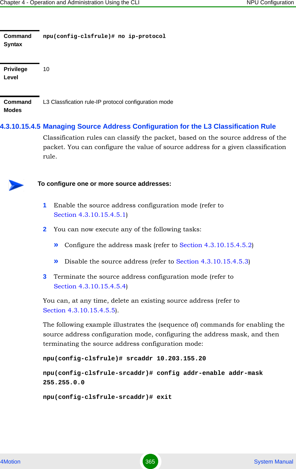
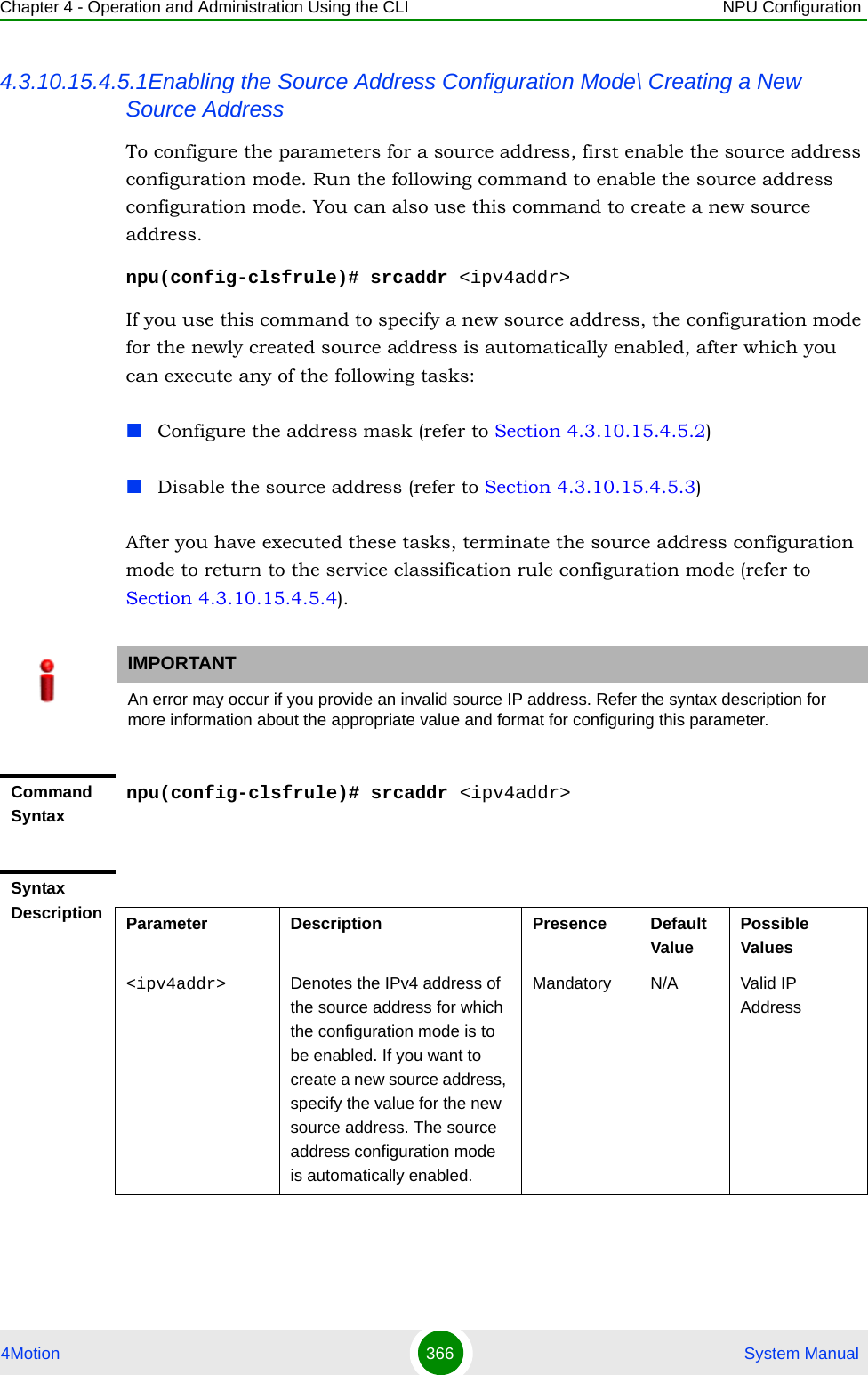
![Chapter 4 - Operation and Administration Using the CLI NPU Configuration4Motion 367 System Manual4.3.10.15.4.5.2Configuring the Address MaskAfter enabling the source address configuration mode, run the following command to configure the address mask for the source address. npu(config-clsfrule-srcaddr)# config [addr-enable] [addr-mask <value>]You can also run this command to enable a source address that is currently disabled. For details, refer to “Disabling the Source Address” on page 368.Command ModesL3 Classification rules configuration modeIMPORTANTAn error may occur if you provide an invalid address mask for the source address. Refer the syntax description for more information about the appropriate value and format for this parameter.Command Syntaxnpu(config-clsfrule-srcaddr)# config [addr-enable] [addr-mask <value>]Privilege Level10Syntax Description Parameter Description Presence Default Value Possible Values[addr-enable] Indiactes that the use of the associated source address is enabled for the classification rule that you are configuring. If the use of this address is disabled, the associated source address is ignored while classifying the packet. Optional By default, the use of the associated source address is disabled.The presence/absence of this flag indicates that the use of the associated source address is enabled/disabled.[addr-mask <value>]Denotes the mask field that is used to specify a range of source addresses.Optional 255.255.255.255Valid address mask](https://usermanual.wiki/Alvarion-Technologies/BMAX-OR-25.Manual-2/User-Guide-1114030-Page-271.png)
![Chapter 4 - Operation and Administration Using the CLI NPU Configuration4Motion 368 System Manual4.3.10.15.4.5.3Disabling the Source AddressYou can run the following command to disable the source address that is currently enabled:npu(config-clsfrule-srcaddr)# no addr-enable4.3.10.15.4.5.4Terminating the Source Address Configuration ModeRun the following command to terminate the source address configuration mode:npu(config-clsfrule-srcaddr)# exitCommand ModesL3 Classification rules-source address configuration modeIMPORTANTTo enable this source address, run the following command: npu(config-clsfrule-srcaddr)# config [addr-enable] [addr-mask <value>]For details, refer to “Configuring the Address Mask” on page 367.Command Syntaxnpu(config-clsfrule-srcaddr)# no addr-enablePrivilege Level10Command ModesL3 Classification rules-source address configuration modeCommand Syntaxnpu(config-clsfrule-srcaddr)# exitPrivilege Level10Command ModesL3 Classfication rule-source address configuration mode](https://usermanual.wiki/Alvarion-Technologies/BMAX-OR-25.Manual-2/User-Guide-1114030-Page-272.png)
![Chapter 4 - Operation and Administration Using the CLI NPU Configuration4Motion 369 System Manual4.3.10.15.4.5.5Deleting Source Addresses You can, at any time, run the following command to delete one or all source addressesnpu(config-clsfrule)# no srcaddr [<ipv4addr>]CAUTIONSpecify the IP address if you want to delete a specific source address. Otherwise all the configured source addresses are deleted.IMPORTANTAn error may occur if you provide an invalid IP address. Refer the syntax description for more information about the appropriate values and format for configuring this parameter.Command Syntaxnpu(config-clsfrule)# no srcaddr [<ipv4addr>]Privilege Level10Syntax Description Parameter Description Presence Default ValuePossible Values[<ipv4addr>] Denotes the IPv4 address of the source address that you want to delete from a classification rule. Specify this parameter only if you want to delete a specific source address. If you do not specify a value for this parameter, all the configured source addresses of the classification rule will be deleted.Optional N/A Valid IP AddressCommand ModesL3 Classification rules configuration mode](https://usermanual.wiki/Alvarion-Technologies/BMAX-OR-25.Manual-2/User-Guide-1114030-Page-273.png)
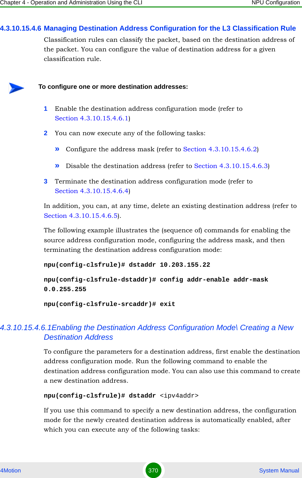
![Chapter 4 - Operation and Administration Using the CLI NPU Configuration4Motion 371 System ManualConfigure the address mask (refer to Section 4.3.10.15.4.6.2)kDisable the destination address (refer to Section 4.3.10.15.4.6.3)After you execute these tasks, you can terminate the destination address configuration mode (refer to Section 4.3.10.15.4.6.4) and return to the classification rules configuration mode.4.3.10.15.4.6.2Configuring the Address MaskRun the following command to configure the address mask for the destination address. npu(config-clsfrule-dstaddr)# config [addr-enable] [addr-mask <value>]IMPORTANTAn error may occur if you provide an invalid destination IP address. Refer the syntax description for more information about the appropriate values and format for configuring this parameter.Command Syntaxnpu(config-clsfrule)# dstaddr <ipv4addr>Privilege Level10Syntax Description Parameter Description Presence Default ValuePossible Values<ipv4addr> Denotes the IPv4 address of the destination address for which the configuration mode is to be enabled. If you want to create a new destination address, specify the value for the new destination address. The destination address configuration mode is automatically enabled.Mandatory N/A Valid IP AddressCommand ModesL3 Classification rules configuration mode](https://usermanual.wiki/Alvarion-Technologies/BMAX-OR-25.Manual-2/User-Guide-1114030-Page-275.png)
![Chapter 4 - Operation and Administration Using the CLI NPU Configuration4Motion 372 System ManualYou can also run this command to enable a destination address that is currently disabled. For details, refer to “Disabling the Destination Address” on page 372.4.3.10.15.4.6.3Disabling the Destination AddressRun the following command to disable the destination address that is currently enabled:npu(config-clsfrule-dstaddr)# no addr-enableIMPORTANTAn error may occur if you provide an invalid address mask. Refer the syntax description for more information about the appropriate values and format for configuring this parameter.Command Syntaxnpu(config-clsfrule-dstaddr)# config [addr-enable] [addr-mask <value>]Privilege Level10Syntax Description Parameter Description Presence Default Value Possible Values[addr-enable] Indicates that the use of the associated destination address is enabled for the classification rule that you are configuring. If the use of this address is disabled, the associated destination address is ignored while classifying the packet. Optional By default, the use of the associated destination address is disabled.The presence/absence of this flag indicates that the use of the associated destination address is enabled/disabled.[addr-mask <value>]Denotes the mask field that is used to specify a range of destination addresses.Optional 255.255.255.255 Valid address maskCommand ModesL3 Classification rules-destination address configuration mode](https://usermanual.wiki/Alvarion-Technologies/BMAX-OR-25.Manual-2/User-Guide-1114030-Page-276.png)
![Chapter 4 - Operation and Administration Using the CLI NPU Configuration4Motion 373 System Manual4.3.10.15.4.6.4Terminating the Destination Address Configuration ModeRun the following command to terminate the destination address configuration mode:npu(config-clsfrule-dstaddr)# exit4.3.10.15.4.6.5Deleting Destination Addresses You can, at any time, run the following command to delete one or all destination addressesnpu(config-clsfrule)# no dstaddr [<ipv4addr>]Command Syntaxnpu(config-clsfrule-dstaddr)# no addr-enablePrivilege Level10Command ModesL3 Classification rules-destination address configuration modeCommand Syntaxnpu(config-clsfrule-dstaddr)# exitPrivilege Level10Command ModesL3 Classfication rule-destination address configuration modeCAUTIONSpecify the IP address if you want to delete a specific destination address. Otherwise all the configured destination addresses are deleted.IMPORTANTAn error may occur if you provide an invalid IP address. Refer the syntax description for more information about the appropriate values and format for configuring this parameter.](https://usermanual.wiki/Alvarion-Technologies/BMAX-OR-25.Manual-2/User-Guide-1114030-Page-277.png)
![Chapter 4 - Operation and Administration Using the CLI NPU Configuration4Motion 374 System Manual4.3.10.15.4.7 Managing Source Port Configuration for the L3 Classification RuleClassification can be based on the source port of the packet. You can configure the value of a source port for a given classification rule.1Enable the source port configuration mode (refer to Section 4.3.10.15.4.7.1)2Enable/disable the source port range (refer to Section 4.3.10.15.4.7.2/Section 4.3.10.15.4.7.3)3Terminate the source port configuration mode (refer to Section 4.3.10.15.4.7.4)In addition, you can, at any time, delete an existing source port configuration (refer to Section 4.3.10.15.4.7.5).The following example illustrates the (sequence of) commands for enabling the source port configuration mode, enabling the source port range, and then terminating the source port configuration mode:Command Syntaxnpu(config-clsfrule)# no dstaddr [<ipv4addr>]Privilege Level10Syntax Description Parameter Description Presence Default ValuePossible Values[<ipv4addr>] Denotes the IPv4 address of the destination address that you want to delete from a classification rule. Specify this parameter only if you want to delete a specific destination address.Optional N/A Valid IP AddressCommand ModesL3 Classification rules configuration modeTo configure one or more source ports:](https://usermanual.wiki/Alvarion-Technologies/BMAX-OR-25.Manual-2/User-Guide-1114030-Page-278.png)
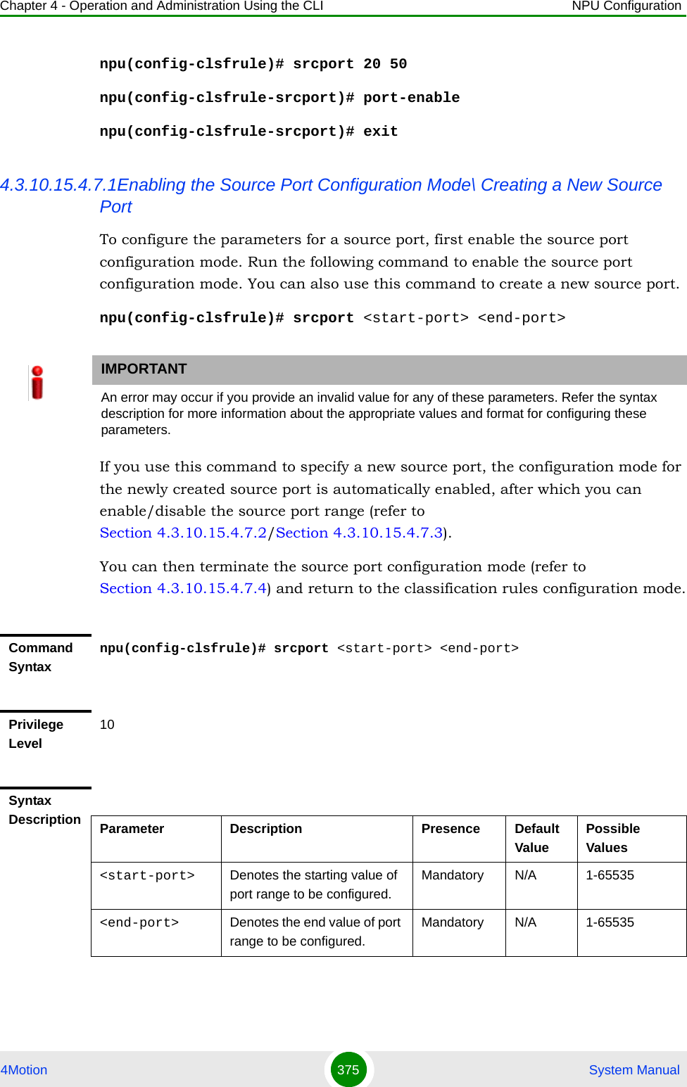
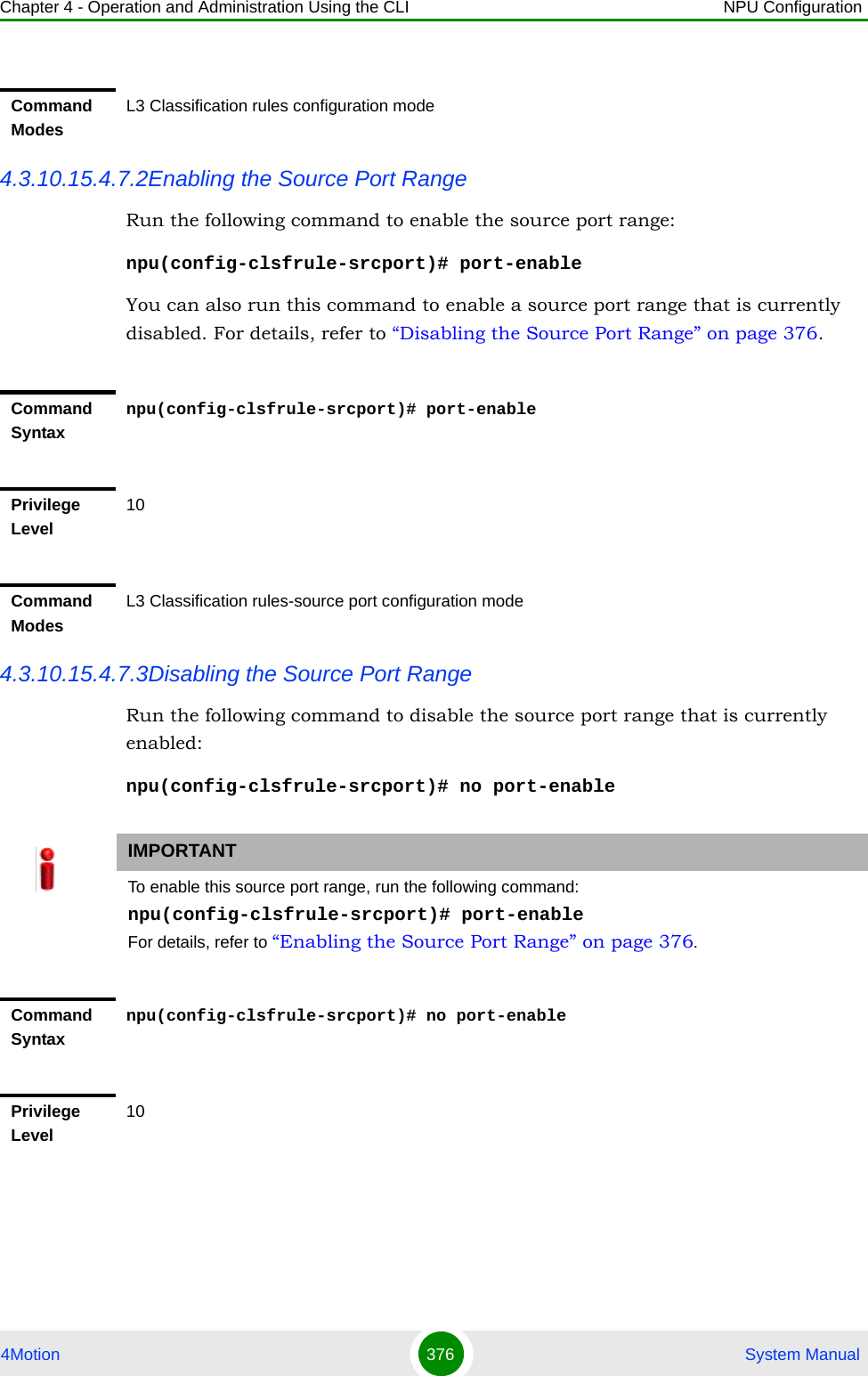
![Chapter 4 - Operation and Administration Using the CLI NPU Configuration4Motion 377 System Manual4.3.10.15.4.7.4Terminating the Source Port Configuration ModeRun the following command to terminate the source port configuration mode:npu(config-clsfrule-srcport)# exit4.3.10.15.4.7.5Deleting Source Ports Run the following command to delete one or all source portsnpu(config-clsfrule)# no srcport [<start-port> <end-port>]Command ModesL3 Classification rules-source port configuration modeCommand Syntaxnpu(config-clsfrule-srcport)# exitPrivilege Level10Command ModesL3 Classfication rule-source port configuration modeCAUTIONSpecify the start and end port numbers if you want to delete a specific souce port. Otherwise all the configured source ports are deleted.IMPORTANTAn error may occur if you provide an invalid value for the start-port and end-port parameters. Refer the syntax description for more information about the appropriate values and format for configuring these parameters.Command Syntaxnpu(config-clsfrule)# no srcport [<start-port> <end-port>]Privilege Level10](https://usermanual.wiki/Alvarion-Technologies/BMAX-OR-25.Manual-2/User-Guide-1114030-Page-281.png)
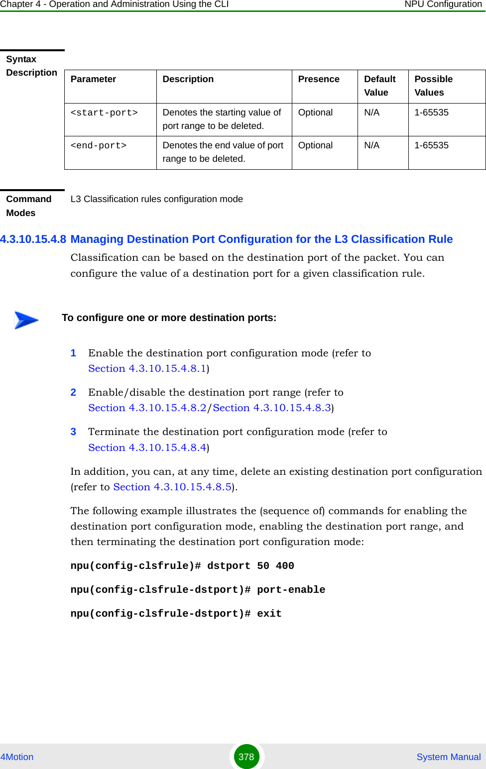
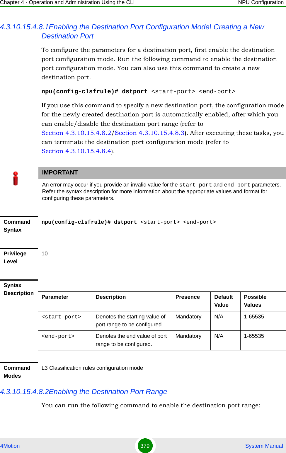
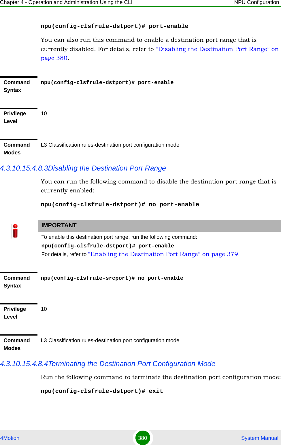
![Chapter 4 - Operation and Administration Using the CLI NPU Configuration4Motion 381 System Manual4.3.10.15.4.8.5Deleting Destination Ports Run the following command to delete one or all destination portsnpu(config-clsfrule)# no dstport [<start-port> <end-port>]Command Syntaxnpu(config-clsfrule-dstport)# exitPrivilege Level10Command ModesL3 Classfication rule-destination port configuration modeCAUTIONSpecify the start and end port numbers if you want to delete a specific destination port. Otherwise all the configured destination ports are deleted.IMPORTANTAn error may occur if you provide an invalid value for the start-port and end-port parameters. Refer the syntax description for more information about the appropriate values and format for configuring these parameters.Command Syntaxnpu(config-clsfrule)# no dstport [<start-port> <end-port>]Privilege Level10Syntax Description Parameter Description Presence Default ValuePossible Values<start-port> Denotes the starting value of port range to be deleted.Optional N/A 1-65535<end-port> Denotes the end value of port range to be deleted.Optional N/A 1-65535](https://usermanual.wiki/Alvarion-Technologies/BMAX-OR-25.Manual-2/User-Guide-1114030-Page-285.png)
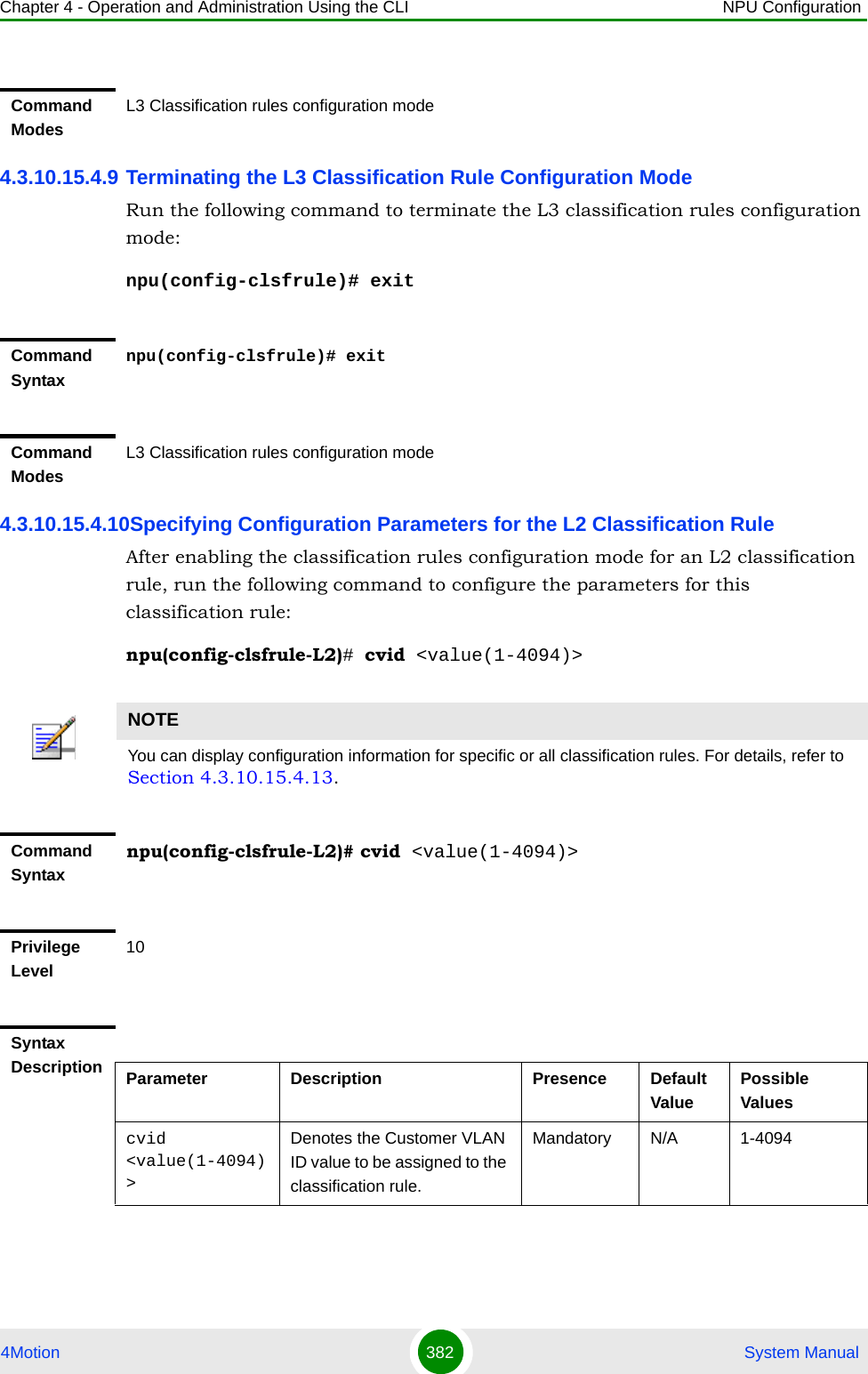
![Chapter 4 - Operation and Administration Using the CLI NPU Configuration4Motion 383 System Manual4.3.10.15.4.11Clearing the configuration of the L3 Classification RuleRun the following command to clear the configuration of this classification rule (removing the configured cvid):npu(config-clsfrule-L2)# no cvidAfter clearing the configuration you can define a new cvid for this classification rule.4.3.10.15.4.12Terminating the L2 Classification Rule Configuration ModeRun the following command to terminate the L2 classification rules configuration mode:npu(config-clsfrule-L2)# exit4.3.10.15.4.13Displaying Configuration Information for Classification Rules To display all or specific classification rules, run the following command:npu# show clsf-rule [<rulename>]Specify the classification rule name if you want to display configuration information for a particular rule. Do not specify a value for this parameter if you want to view configuration information for all classification rules.Command ModesL2 Classification rules configuration modeCommand Syntaxnpu(config-clsfrule-L2)# no cvidPrivilege Level10Command ModesL2 Classification rules configuration modeCommand Syntaxnpu(config-clsfrule-L2)# exitCommand ModesL2 Classification rules configuration mode](https://usermanual.wiki/Alvarion-Technologies/BMAX-OR-25.Manual-2/User-Guide-1114030-Page-287.png)
![Chapter 4 - Operation and Administration Using the CLI NPU Configuration4Motion 384 System ManualIMPORTANTAn error may occur if you provide an invalid value for the rulename parameter. Refer the syntax description for more information about the appropriate values and format for configuring this parameters.Command Syntaxnpu# show clsf-rule [<rulename>]Privilege Level1Syntax Description Parameter Description Presence Default ValuePossible Values[<rulename>] Denotes the name of the classification rule that you want to display. Specify this parameter only if you want to display a specific classification rule. If you do not specify a rule name, it displays all configured classification rules.Optional N/A StringDisplay Format for each L3 rule Classification Rule Configuration : ClsfRulename <value> clsfRuleType: L3 Priority <value> Phs rulename <value> IpTosLow <value> IpTosHigh <value> IpTosMask <value> IpTosEnable <0/1> clsfRuleSrcAddr <value> clsfRuleMask <value> SrcAddrEnable <0/1> clsfRuleDstAddr <value> clsfRuleAddrMask <value> DstAddrenable <0/1> clsfRuleSrcPort Start <value> clsfRuleSrcPort End <value> clsfRulePortEnable <0/1> clsfRuleDstPort Start <value> clsfRuleDstPort End <value> clsfRulePortEnable <0/1>](https://usermanual.wiki/Alvarion-Technologies/BMAX-OR-25.Manual-2/User-Guide-1114030-Page-288.png)
![Chapter 4 - Operation and Administration Using the CLI NPU Configuration4Motion 385 System Manual4.3.10.15.4.14Deleting Classification RulesRun the following command to delete one or all classification rules:npu(config)# no clsf-rule [<rulename>]Display Format for each L2 ruleClsfRulename <value>clsfRuleType: L2Cvid <value>Command ModesGlobal command modeCAUTIONSpecify the rule name if you want to delete a specific classification. Otherwise all the configured classification rules are deleted.Command Syntaxnpu(config)# no clsf-rule [<rulename>]Privilege Level10Syntax Description Parameter Description Presence Default ValuePossible Values[<rulename>] Denotes the name of the classification rule that you want to delete. Specify this parameter only if you want to delete a specific classification rule, otherwise all configured classification rules are deleted.Optional N/A StringCommand ModesGlobal configuration mode](https://usermanual.wiki/Alvarion-Technologies/BMAX-OR-25.Manual-2/User-Guide-1114030-Page-289.png)
![Chapter 4 - Operation and Administration Using the CLI NPU Configuration4Motion 387 System Manualnpu(config-phsrule)# config field 000000000000000000000000FFFFFFFF00000000 mask 000F00 verify 0 size 20npu(config-phsrule)# exit4.3.10.16.1 Enabling the PHS Rules Configuration Mode /Creating a New PHS RuleTo configure the parameters for a PHS rule, first enable the PHS rules configuration mode. Run the following command to enable the PHS rules configuration mode. You can also use this command to create a new PHS rule.npu(config)# phs-rule <rulename>If you use this command to create a new PHS rule, the configuration mode for this PHS rule is automatically enabled, after which you can configure the parameters for the PHS rule (refer to Section 4.3.10.16.2). You can then terminate the PHS rules configuration mode (refer to Section 4.3.10.16.3) and return to the global configuration mode.4.3.10.16.2 Configuring Parameters for the PHS RuleRun the following command to configure the parameters of the PHS rule:npu(config-phsrule)# config <[field <value>] [mask <value>] [verify <value>] [size <value>]>Command Syntaxnpu(config)# phs-rule <rulename>Privilege Level10Syntax Description Parameter Description Presence Default ValuePossible Values<rulename> Denotes the PHS rule for which the PHS configuration mode is to be enabled.Mandatory N/A String (1 to 11 characters)Command ModesGlobal configuration mode](https://usermanual.wiki/Alvarion-Technologies/BMAX-OR-25.Manual-2/User-Guide-1114030-Page-291.png)
![Chapter 4 - Operation and Administration Using the CLI NPU Configuration4Motion 388 System ManualNOTEYou can display configuration information for specific or all PHS rules. For details, refer Section 4.3.10.16.5.IMPORTANTAn error may occur if you provide an invalid value for any of these parameters. Refer the syntax description for more information about the appropriate values and format for configuring these parameters.Command Syntaxnpu(config-phsrule)# config <[field <value>] [mask <value>] [verify <value>] [size <value>]>Privilege Level10Syntax Description Parameter Description Presence Default ValuePossible Values[field <value>] Denotes the PHSF value, that is, the header string to be suppressed. Mandatory N/A String. This parameter is of format "0x0000000000000000000000000000000000000000". Here Octet(x), x=20 bytes, each Byte will represent two characters when used as string like in xml file.](https://usermanual.wiki/Alvarion-Technologies/BMAX-OR-25.Manual-2/User-Guide-1114030-Page-292.png)
![Chapter 4 - Operation and Administration Using the CLI NPU Configuration4Motion 389 System Manual4.3.10.16.3 Terminating the PHS Rules Configuration ModeRun the following command to terminate the PHS rules configuration mode:npu(config-phsrule)# exit[mask <value>] Indicates the PHSM, which contains the bit-mask of the PHSF with the bits set that is to be suppressed.Mandatory N/A String This parameter is of format "0x000000". Here Octet(x), x=3 bytes, each Byte will represent two characters when used as string like in xml file.[verify <value>] Indicates whether the PHS header is to be verified.Optional 0 (No) 0: Indicates that the PHS header should be verified.1: Indicates that the PHS header should not be verified.[size <value>]Indicates the size in bytes of the header to be suppressed.Mandatory N/A 0-20Command ModesPHS rules configuration modeCommand Syntaxnpu(config-phsrule)# exitPrivilege Level10Command ModesPHS rulesconfiguration mode](https://usermanual.wiki/Alvarion-Technologies/BMAX-OR-25.Manual-2/User-Guide-1114030-Page-293.png)
![Chapter 4 - Operation and Administration Using the CLI NPU Configuration4Motion 390 System Manual4.3.10.16.4 Deleting PHS RulesRun the following command to delete one or all PHS rules:npu(config)# no phs-rule [<rulename>]4.3.10.16.5 Displaying Configuration Information for PHS Rules To display all or specific PHS rules, run the following command:npu# show phs-rule [<rulename>]Specify the rule name if you want to display configuration information for a particular PHS rule. Do not specify a value for this parameter if you want to view configuration information for all PHS rule.CAUTIONSpecify the rule name if you want to delete a specific PHS rule. Otherwise all the configured PHS rules are deleted.Command Syntaxnpu(config)# no phs-rule [<rulename>]Privilege Level10Syntax Description Parameter Description Presence Default ValuePossible Values[<rulename>] Denotes the rule name of the PHS rule that you want to delete. Specify a value for this parameter if you want to delete a specific PHS rule. Do not specify a value for this parameter, if you want to delete all PHS rules. Optional N/A StringCommand ModesClassfication rule-IP protocol configuration mode](https://usermanual.wiki/Alvarion-Technologies/BMAX-OR-25.Manual-2/User-Guide-1114030-Page-294.png)
![Chapter 4 - Operation and Administration Using the CLI NPU Configuration4Motion 391 System Manual4.3.10.17 Managing the ASN-GW Keep-Alive FunctionalityOnce an MS enters the network, its context is stored in ASN entities (BS, ASN-GW). Dynamically, MS context could be transferred/updated (during HO and re-authentication) to other entities or duplicated to other entities (separation between anchor functions such as Authenticator, Data Path and Relay Data Path).IMPORTANTAn error may occur if you provide an invalid value for the rulename parameter. Refer the syntax description for more information about the appropriate values and format for configuring this parameter.Command Syntaxnpu# show phs-rule [<rulename>]]Privilege Level1Syntax Description Parameter Description Presence Default ValuePossible Values[<rulename>] Denotes the rule name of the PHS rule that you want to delete. Specify a value for this parameter if you want to delete a specific PHS rule. Do not specify a value for this parameter, if you want to delete all PHS rules. Optional N/A StringDisplay FormatPHS Configuration :rulename field mask verify size<value> <value> <value> <value> <value>…….Command ModesGlobal command mode](https://usermanual.wiki/Alvarion-Technologies/BMAX-OR-25.Manual-2/User-Guide-1114030-Page-295.png)
![Chapter 4 - Operation and Administration Using the CLI NPU Configuration4Motion 393 System Manualreset (through calculation of difference between polled entity "Last-Reset-Time" received on poll N+1 and self UTC).If the ASN-GW is the authenticator for the MS(s) the failing BS served, then in addition to context clearance it also sends R3 Accounting-Request (Stop) message including a release indication to AAA.If ASN-GW is the Data Path Function for the MS(s) that the failing BS/Relay Data Path ASN-GW served, then in addition to context clearance it also sends R4 NetExit_MS_State_Change_Req (or equivalent - according to R6 IOT spec procedure) message to the Authenticator which in turn sends R3 Accounting-Request (Stop) message including a release indication to AAAWhen keep-alive fails, ASN-GW generates an alarm and log the event.Regardless of the enable/disable status of the keep-alive mechanism in the ASN-GW, it replies to ASN_Keep_Alive_Req received from other ASN-GWs/BSs with ASN_Keep_Alive_Rsp. that includes also its "Last-Reset-Time". It responds only if all its functions operate properly. In case one of the functions fails, the ASN-GW shall not respond to the keep-alive poll.4.3.10.17.1 Configuring ASN-GW Keep-Alive ParametersTo configure one or several keep-alive parameters, run the following command:npu(config)# set keep-alive ([asnGwKeepAliveTmr <integer (10-1000)>] [asnGwKeepAliveRtxLmt <integer (1-10)>] [asnGwKeepAliveRespTmr <integer (100-10000)>] [asnKeepAliveEnable <enable|disable>])Command Syntaxnpu(config)# set keep-alive ([asnGwKeepAliveTmr <integer (10-1000)>] [asnGwKeepAliveRtxLmt <integer (1-10)>] [asnGwKeepAliveRespTmr <integer (100-10000)>] [asnKeepAliveEnable <enable|disable>]) Privilege Level10](https://usermanual.wiki/Alvarion-Technologies/BMAX-OR-25.Manual-2/User-Guide-1114030-Page-297.png)
![Chapter 4 - Operation and Administration Using the CLI NPU Configuration4Motion 394 System Manual4.3.10.17.2 Displaying Configuration Information for ASN-GW Keep-Alive Parameters To display the ASN-GW keep-alive parameters, run the following command:npu# show keep-aliveSyntax Description Parameter Description Presence Default ValuePossible Values[asnGwKeepAliveTmr <integer (10-1000)>]The period ln seconds between polling sessions.asnGwKeepAliveTmr x 1000 (value in milliseconds) cannot be lower than asnGwKeepAliveRespTmr x (asnGwKeepAliveRtxLmt +1).Optional 60 10-1000[asnGwKeepAliveRtxLmt <integer (1-10)>]Maximum number of retries if asnGwKeepAliveRespTmr has expired without getting a response.Optional 3 1-10[asnGwKeepAliveRespTmr <integer (100-10000)>]Time in milliseconds to wait for a response before initiating another polling attempt or reaching a decision that the polled entity has failed (if the maximum number of retries set by asnGwKeepAliveRtxLmt has been reached).Optional 500 100-10000[asnKeepAliveEnable <enable|disable>]Enable/Disable the ASN-GW keep-alive mechanism.Optional disable enabledisableCommand ModesGlobal configuration modeCommand Syntaxnpu# show keep-alive](https://usermanual.wiki/Alvarion-Technologies/BMAX-OR-25.Manual-2/User-Guide-1114030-Page-298.png)
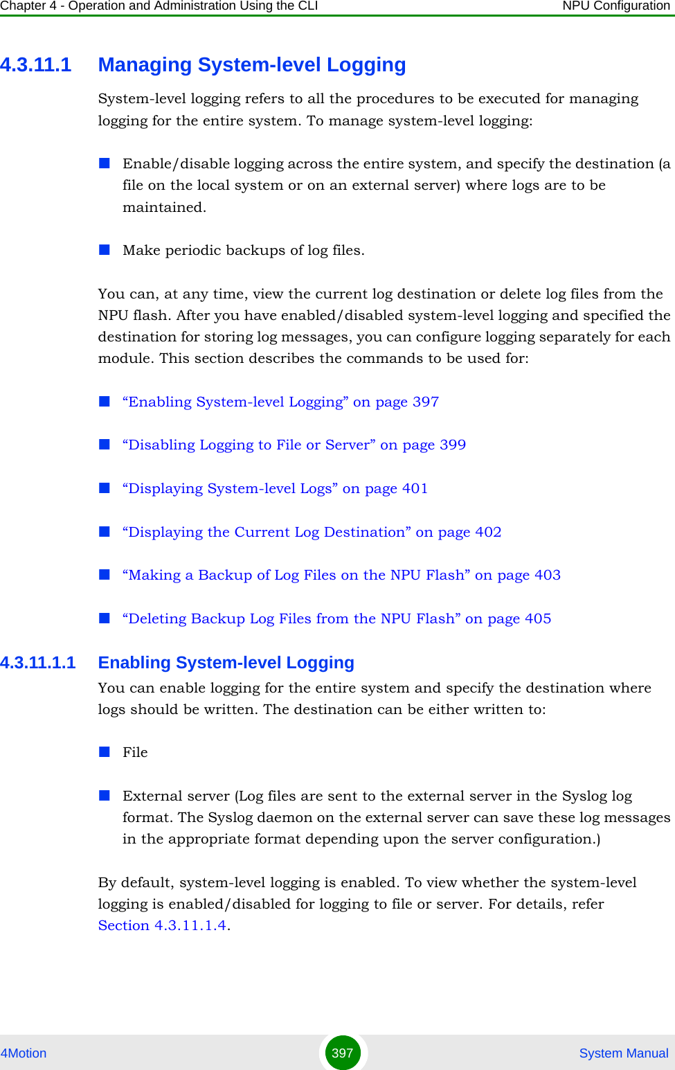
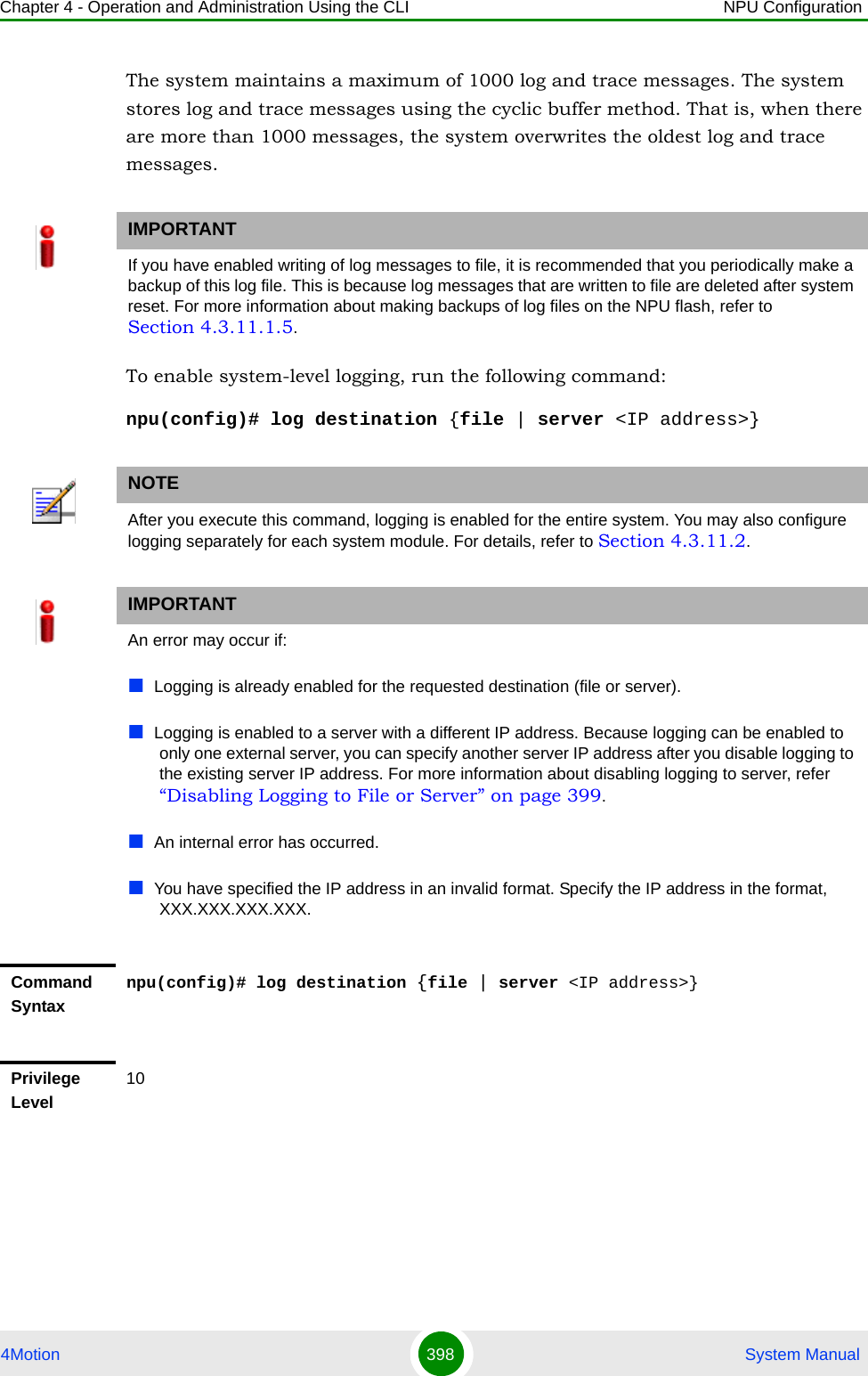
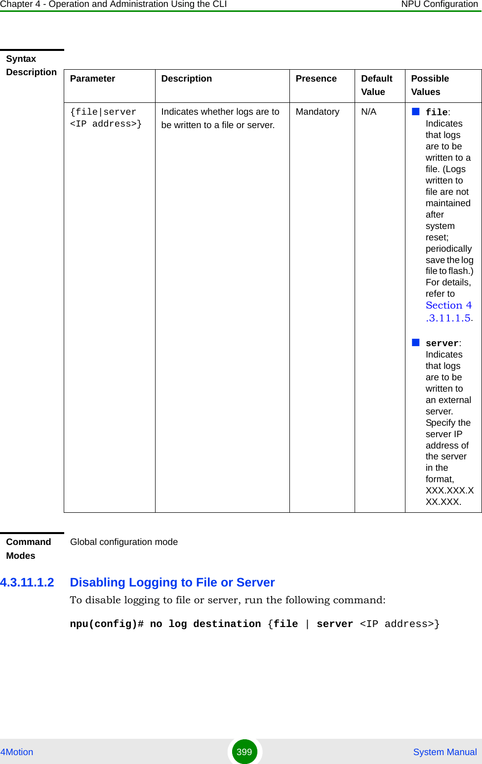
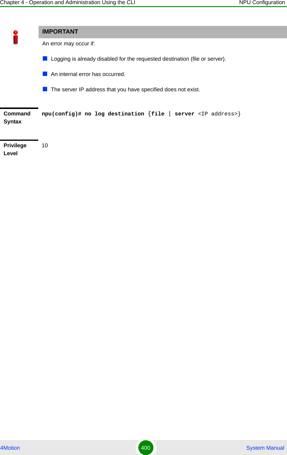
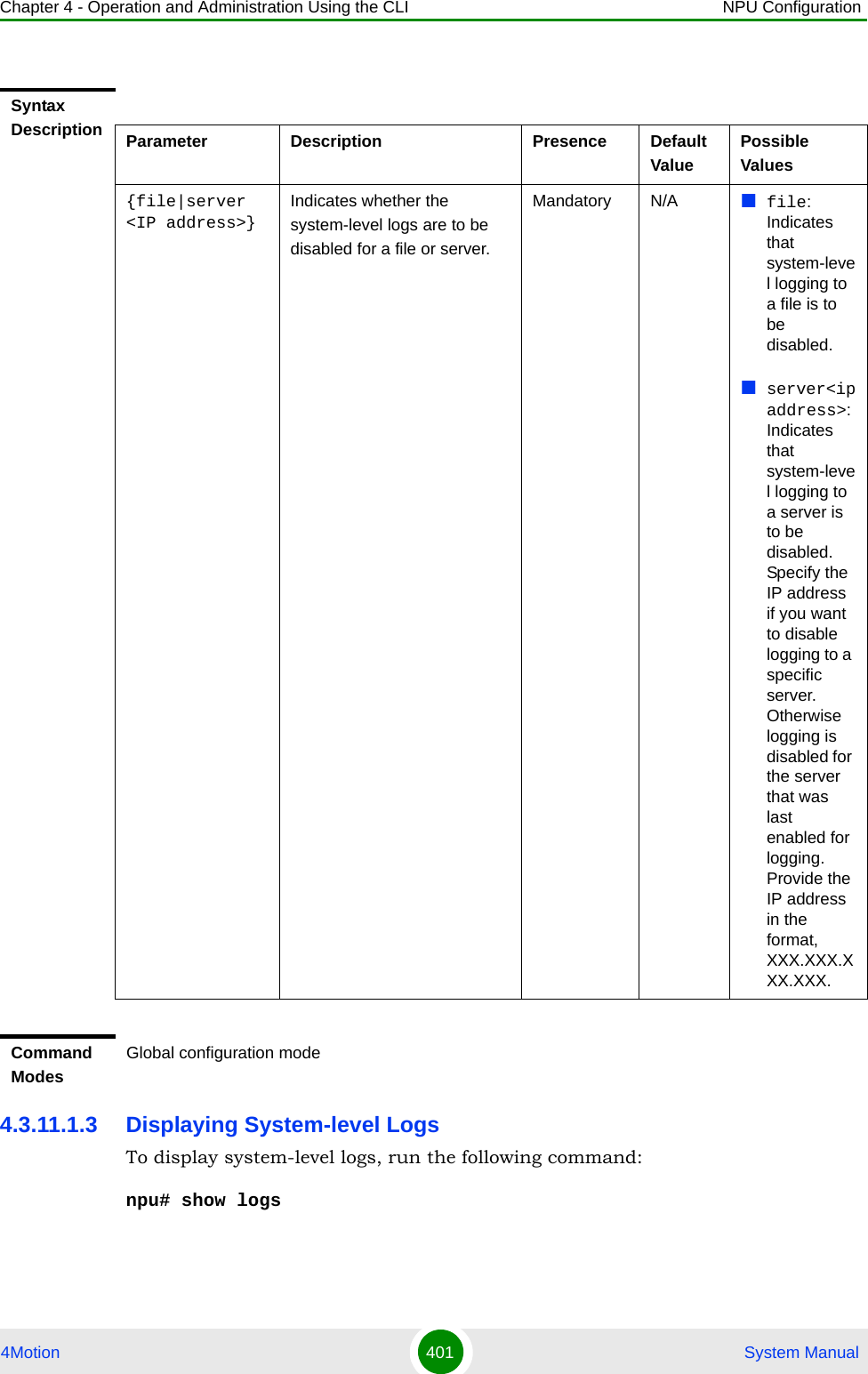
![Chapter 4 - Operation and Administration Using the CLI NPU Configuration4Motion 402 System ManualWhen you run this command, all the log messages are displayed. (4Motion maintains a maximum of 1000 log and trace messages.) If you want to filter log messages to be displayed, run the following command to specify the filter criteria:npu# show logs [filter | grep <string>]For example, if you want to view log messages pertaining to only Error logs, run the following command:npu# show logs filter|grep ERROR4.3.11.1.4 Displaying the Current Log DestinationTo view the current log destination, that is, whether logs are written to file or an external server, run the following command:npu# show log destinationIMPORTANTAn error may occur if:There are no logs to be displayed.The log files are inaccessible or an internal error occurred while processing the result.Command Syntaxnpu# show logs [filter | grep <string>]Privilege Level1Syntax Description Parameter Description Presence Default ValuePossible Values[filter | grep <string>]Indicates the criteria for filtering the log messages to be displayed.Optional N/A StringCommand ModesGlobal command mode](https://usermanual.wiki/Alvarion-Technologies/BMAX-OR-25.Manual-2/User-Guide-1114030-Page-306.png)
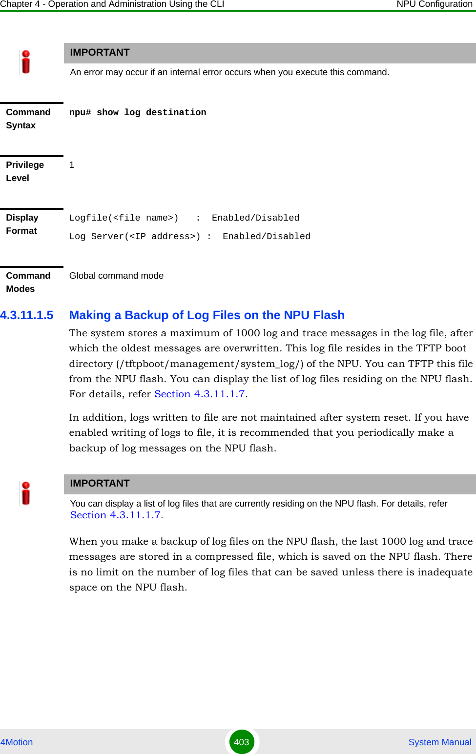
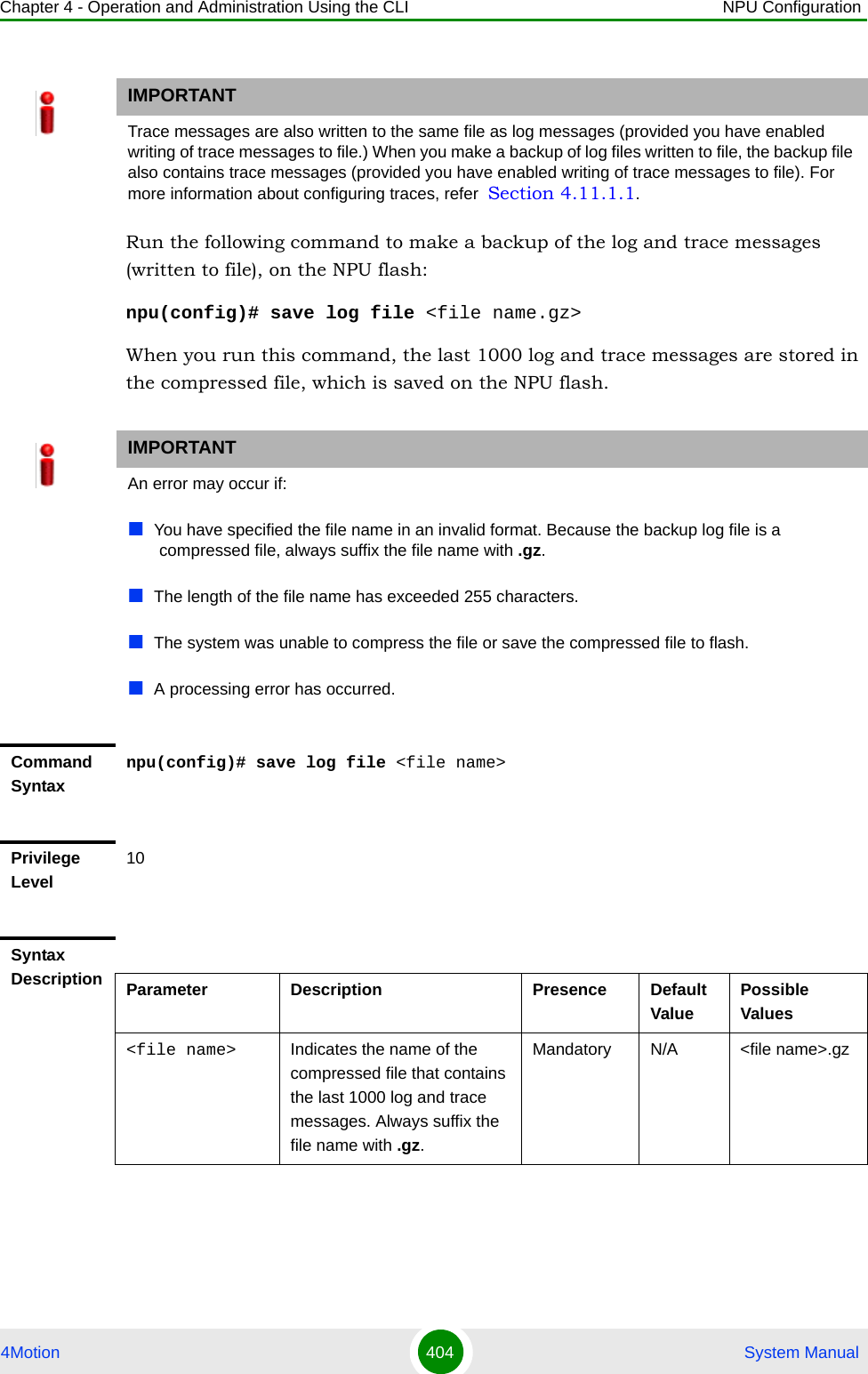
![Chapter 4 - Operation and Administration Using the CLI NPU Configuration4Motion 405 System Manual4.3.11.1.6 Deleting Backup Log Files from the NPU FlashYou can delete the backup log files from the NPU flash. It is recommended that you periodically make a backup of these log files, and delete these from the NPU flash.To delete log and trace backup files from the NPU flash, run the following command:npu(config)# erase log file [<file name>]Command ModesGlobal configuration modeIMPORTANTTrace and log messages are stored in the same backup file on the NPU flash. When you execute this procedure, trace messages are also deleted from the NPU flash. For details, refer to “Managing System-level Tracing” on page 822.CAUTIONSpecify the file name if you want to delete a specific backup file. Otherwise all the backup files residing in the NPU flash are deleted.IMPORTANTAn error may occur if:The file name that you have specified does not exist.A processing error has occurred.Command Syntaxnpu(config)# erase log file [<file name>]Privilege Level10](https://usermanual.wiki/Alvarion-Technologies/BMAX-OR-25.Manual-2/User-Guide-1114030-Page-309.png)
![Chapter 4 - Operation and Administration Using the CLI NPU Configuration4Motion 406 System Manual4.3.11.1.7 Displaying Log Files Residing on the NPU FlashYou can display a list of log files that are residing on the NPU flash. For details, refer Section 4.10.4.4.3.11.2 Configuring Module-level LoggingYou can configure logging (enable/disable) separately for the following modules, and define the severity level for which logging is required:System startup proceduresNPU/AU upgrade proceduresFault management proceduresSystem performance proceduresShelf management proceduresWiMAX signaling protocolsUser interfaceAU management proceduresThis section describes the commands to be used for:Syntax Description Parameter Description Presence Default ValuePossible Values[<file name>] Indicates the name of the compressed log file to be deleted. If you do not specify the file name, all the log files residing in the NPU flash are deleted.Always suffix the file name with .gz.Optional N/A <file name>.gzCommand ModesGlobal configuration mode](https://usermanual.wiki/Alvarion-Technologies/BMAX-OR-25.Manual-2/User-Guide-1114030-Page-310.png)
![Chapter 4 - Operation and Administration Using the CLI NPU Configuration4Motion 407 System Manual“Configuring the Log Severity Level” on page 407“Displaying Configuration Information for Module-level Logging” on page 409“Disabling Module-level Logging” on page 4104.3.11.2.1 Configuring the Log Severity LevelYou can configure the severity level for logs to be generated for each module. This means that if an event occurs for a module for which the severity level is equal to or higher than the configured level, a log is generated. The following are the severity levels (highest to lowest) that can be configured for each module:EmergencyAlertCriticalErrorWarningNotice InformationTo specify the severity level for each module for which logs are to be created, run the following command:npu(config)# log level [{StartupMgr|SWDownload|FaultMgr|PerfMgr|ShelfMgr|SIGASN|UserIF|AUMgr}] {EMERG|ALERT|CRIT|ERROR|WARN|NOTICE|INFO}The parameters in this command correspond to the system modules/procedures listed in the following table:IMPORTANTBy default, logging is enabled for all modules, and the severity level is Error. The severity levels recorded in 4Motion log messages are defined in RFC 3164.](https://usermanual.wiki/Alvarion-Technologies/BMAX-OR-25.Manual-2/User-Guide-1114030-Page-311.png)
![Chapter 4 - Operation and Administration Using the CLI NPU Configuration4Motion 408 System ManualSpecify the module name if you want to configure the severity level separately for this module. If you do not specify the name of the module, the severity level that you configure in this command is applied to all modules. For example, run the following command if you want logs to be created for WiMAX signaling protocols when the severity level is Warning or higher:npu(config)# log level SIGASN WARNOr run the following command to set the severity level to Error for all modules:npu(config)# log level ERRORTable 4-21: Modules for which Logging can be EnabledParameter Refers to...StartupMgr System startup proceduresSWDownload Software upgrade proceduresFaultMgr Fault management proceduresShelfMgr Shelf management proceduresSIGASN WiMAX signaling protocolsUserIF User-initiated proceduresAUMgr Internal processes used for managing AUPerfMgr Performance management proceduresNOTEYou can display the currently configured severity levels for each module. For details, refer Section 4.3.11.2.2.Command Syntaxnpu(config)# log level [{StartupMgr|SWDownload|FaultMgr|PerfMgr|ShelfMgr|SIGASN|UserIF|AUMgr}] {EMERG|ALERT|CRIT|ERROR|WARN|NOTICE|INFO}Privilege Level10](https://usermanual.wiki/Alvarion-Technologies/BMAX-OR-25.Manual-2/User-Guide-1114030-Page-312.png)
![Chapter 4 - Operation and Administration Using the CLI NPU Configuration4Motion 409 System Manual4.3.11.2.2 Displaying Configuration Information for Module-level LoggingTo display the log level configured for one or all modules, run the following command. npu(config)# show log level [{StartupMgr|SWDownload|FaultMgr|PerfMgr|ShelfMgr|SIGASN|UserIF|AUMgr}]Specify the module for which you want to view the configured severity level. If you do not specify the name of the module, the log level configured for all modules is displayed.Syntax Description Parameter Description Presence Default ValuePossible Values[{StartupMgr|SWDownload|FaultMgr|PerfMgr|ShelfMgr|SIGASN|UserIF|AUMgr}]Indicates the name of the module for which the severity level is to be specified.If you do not specify any value for this parameter, the severity level that you specify is applied for all modules. For more information about these parameters, refer Table 4-21.Optional N/A StartupMgrSWDownloadFaultMgrPerfMgrShelfMgrSIGASNUserIFAUMgr{EMERG|ALERT|CRIT|ERROR|WARN|NOTICE|INFO}Indicates the severity level to be applied to a particular or all modules. Mandatory Error EMERGALERTCRITERRORWARNNOTICEINFOCommand ModesGlobal configuration mode](https://usermanual.wiki/Alvarion-Technologies/BMAX-OR-25.Manual-2/User-Guide-1114030-Page-313.png)
![Chapter 4 - Operation and Administration Using the CLI NPU Configuration4Motion 410 System Manual4.3.11.2.3 Disabling Module-level LoggingTo disable logging for one or all system modules, run the following command:npu(config)# no log level [{StartupMgr|SWDownload|FaultMgr|PerfMgr|ShelfMgr|SIGASN|UserIF|AUMgr}]Specify the name of the module if you want to disable logging for a specific module. If you do not specify the module name, logging is disabled for all modules.Command Syntaxnpu(config)# show log level [{StartupMgr|SWDownload|FaultMgr|PerfMgr|ShelfMgr|SIGASN|UserIF|AUMgr}]Privilege Level1Syntax Description Parameter Description Presence Default ValuePossible Values[{StartupMgr|SWDownload|FaultMgr|PerfMgr|ShelfMgr|SIGASN|UserIF|AUMgr}]Indicates the name of the module for which you want to view the configured severity level. For more information about these parameters, refer Table 4-21.If you do not specify any value for this parameter, the severity level is displayed for all modules.Optional N/A StartupMgrSWDownloadFaultMgrPerfMgrShelfMgrSIGASNUserIFAUMgrDisplay FormatModule Name : Log level<Module Name> : <Log Level>Command ModesGlobal configuration mode](https://usermanual.wiki/Alvarion-Technologies/BMAX-OR-25.Manual-2/User-Guide-1114030-Page-314.png)
![Chapter 4 - Operation and Administration Using the CLI NPU Configuration4Motion 411 System Manual4.3.12 Configuring Performance Data CollectionYou can configure 4Motion to periodically collect and store performance counters with respect to the following groups:Command Syntaxnpu(config)# no log level [{StartupMgr|SWDownload|FaultMgr|PerfMgr|ShelfMgr|SIGASN|UserIF|AUMgr}]Privilege Level10Syntax Description Parameter Description Presence Default ValuePossible Values[{StartupMgr|SWDownload|FaultMgr|PerfMgr|ShelfMgr|SIGASN|UserIF|AUMgr}]Indicates the name of the module for which logging is to be disabled.If you do not specify any value for this parameter, logging is disabled for all parameters. For more information about these modules, refer Table 4-21.Optional N/A StartupMgrSWDownloadFaultMgrPerfMgrShelfMgrSIGASNUserIFAUMgrCommand ModesGlobal configuration mode](https://usermanual.wiki/Alvarion-Technologies/BMAX-OR-25.Manual-2/User-Guide-1114030-Page-315.png)
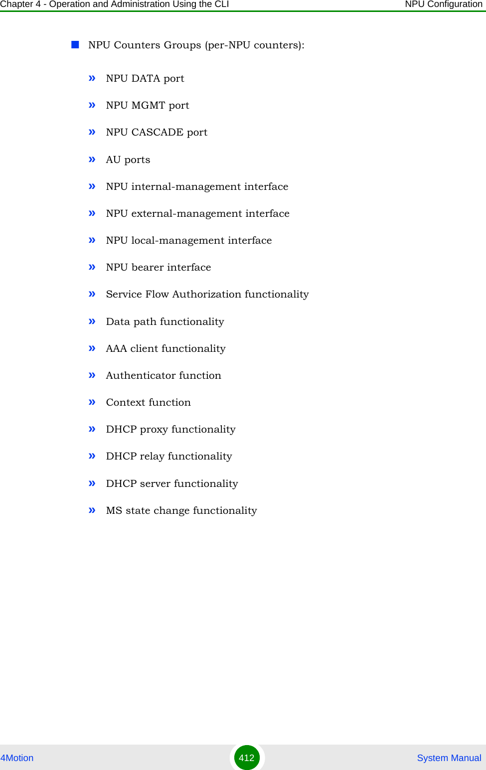
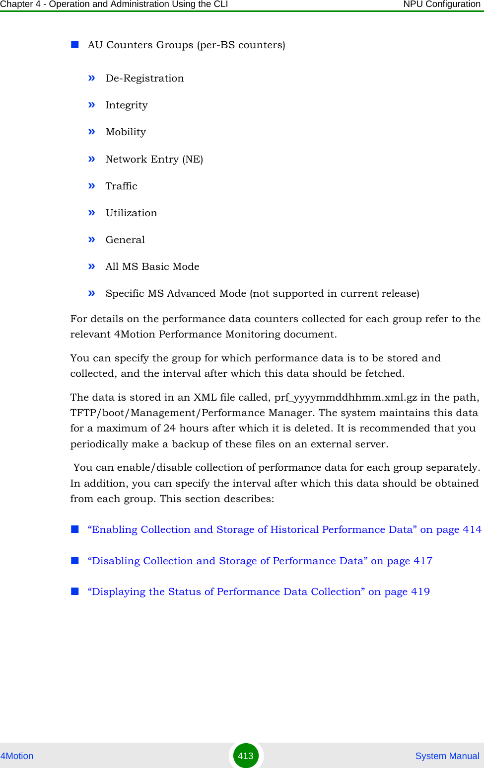
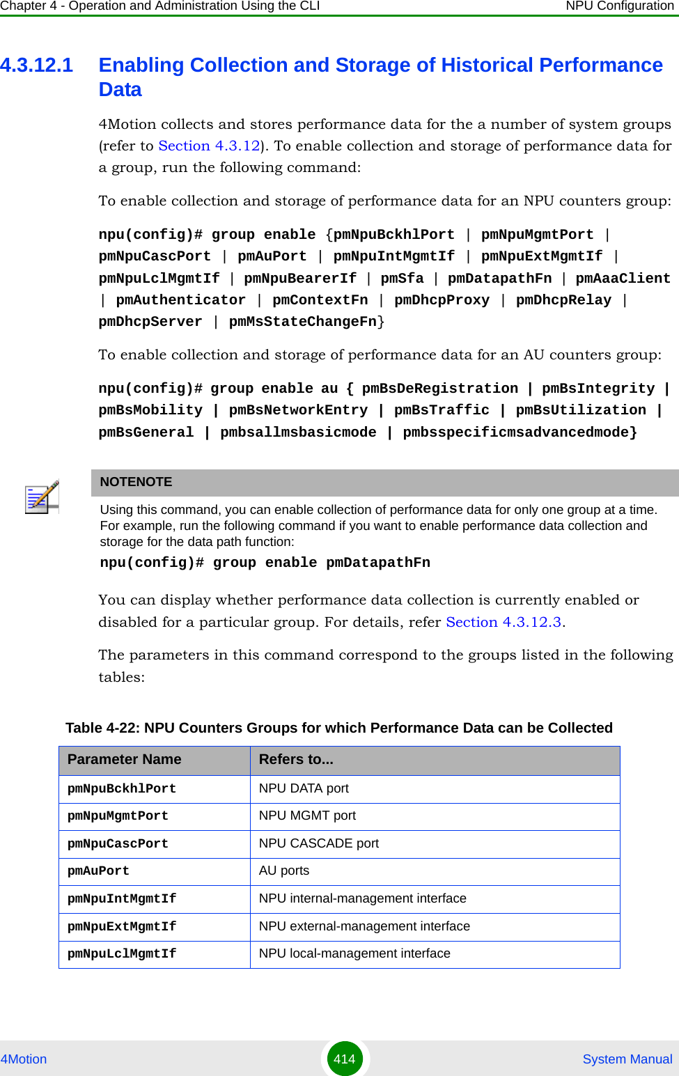
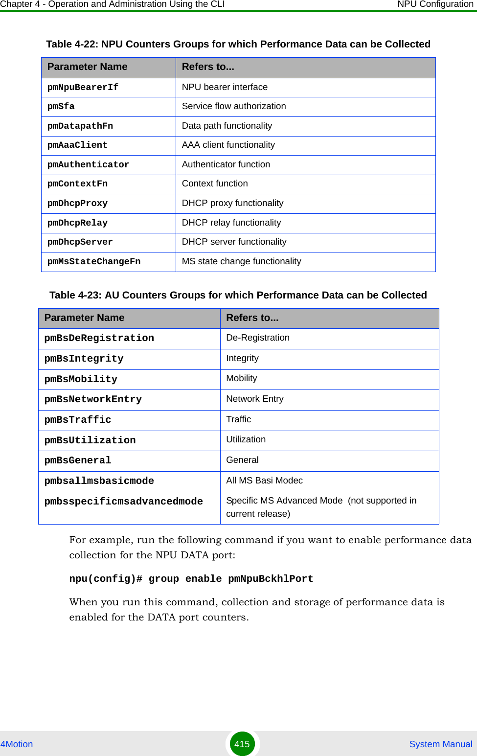
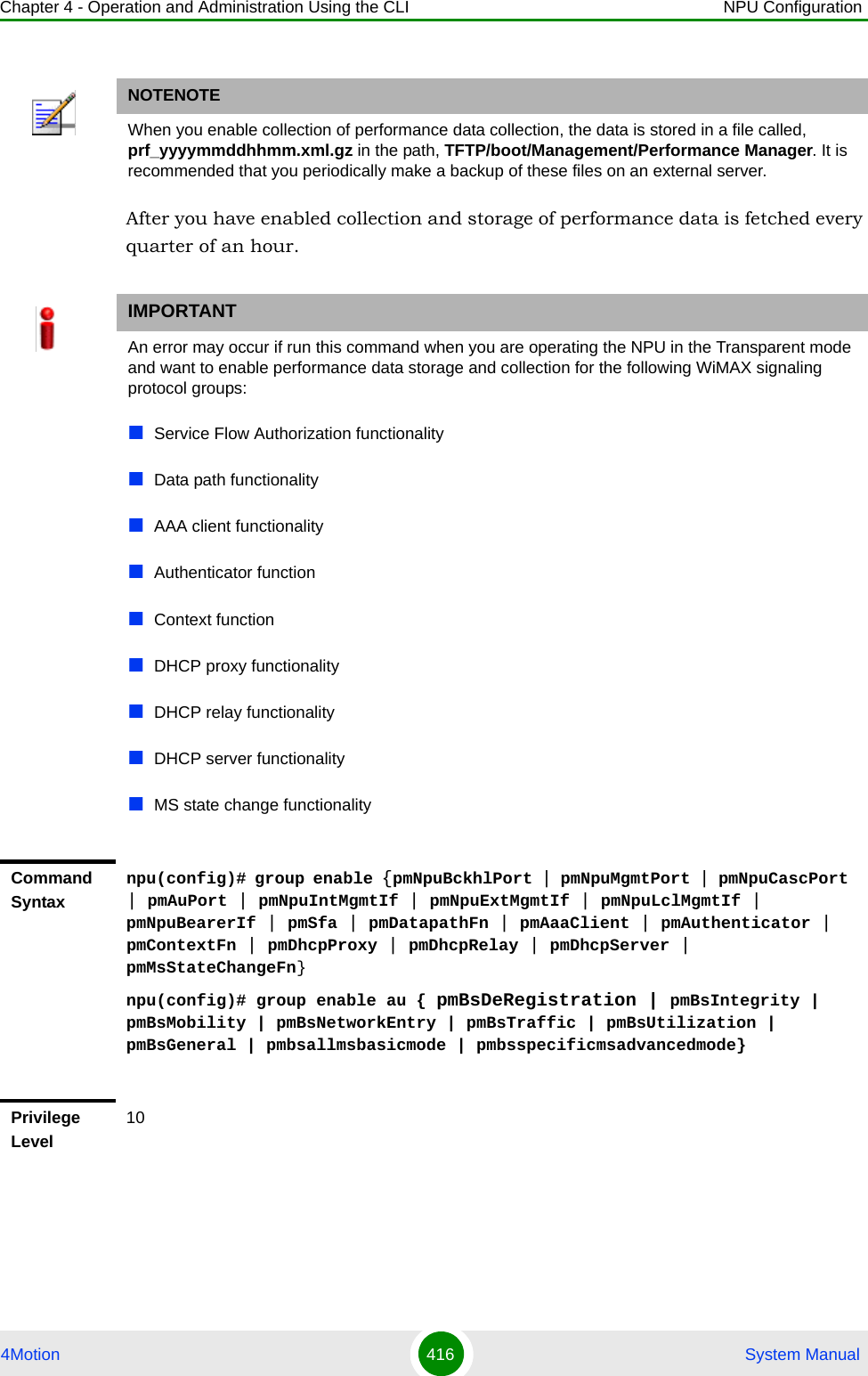
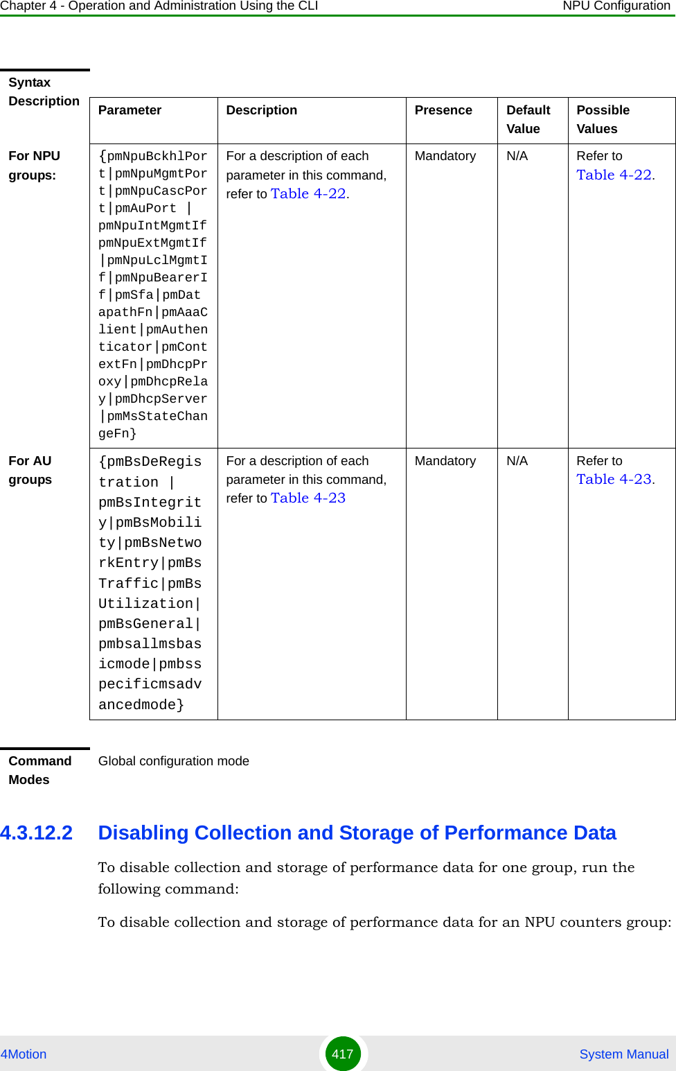
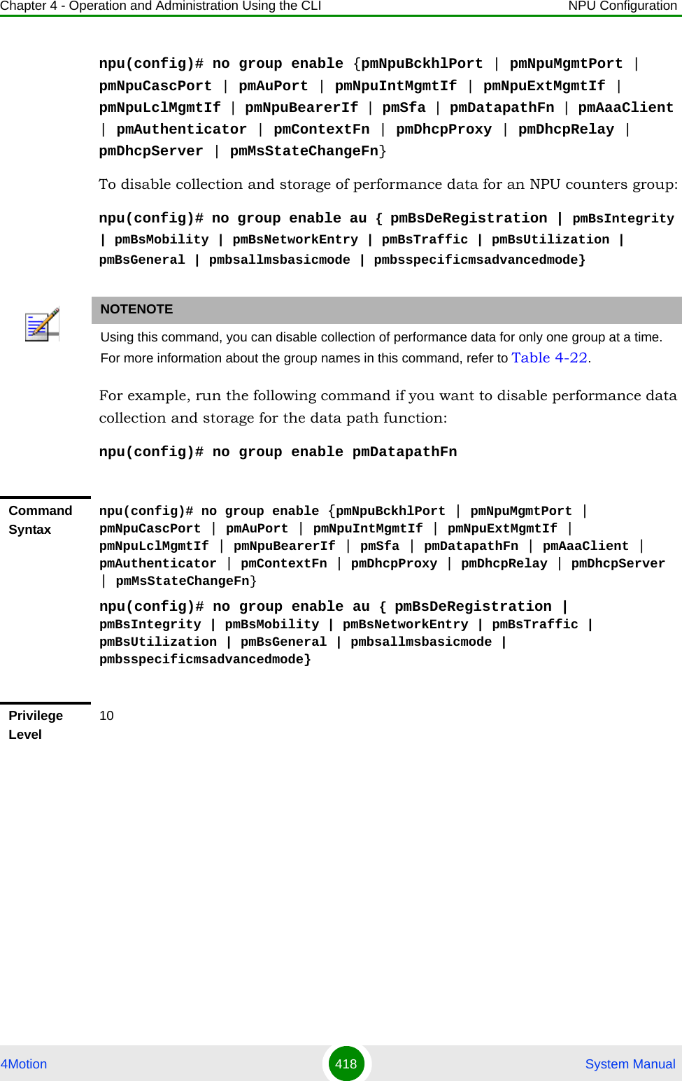
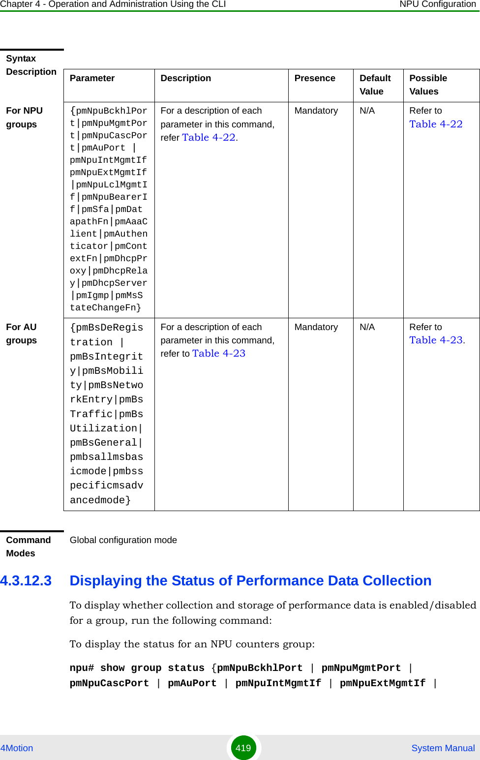
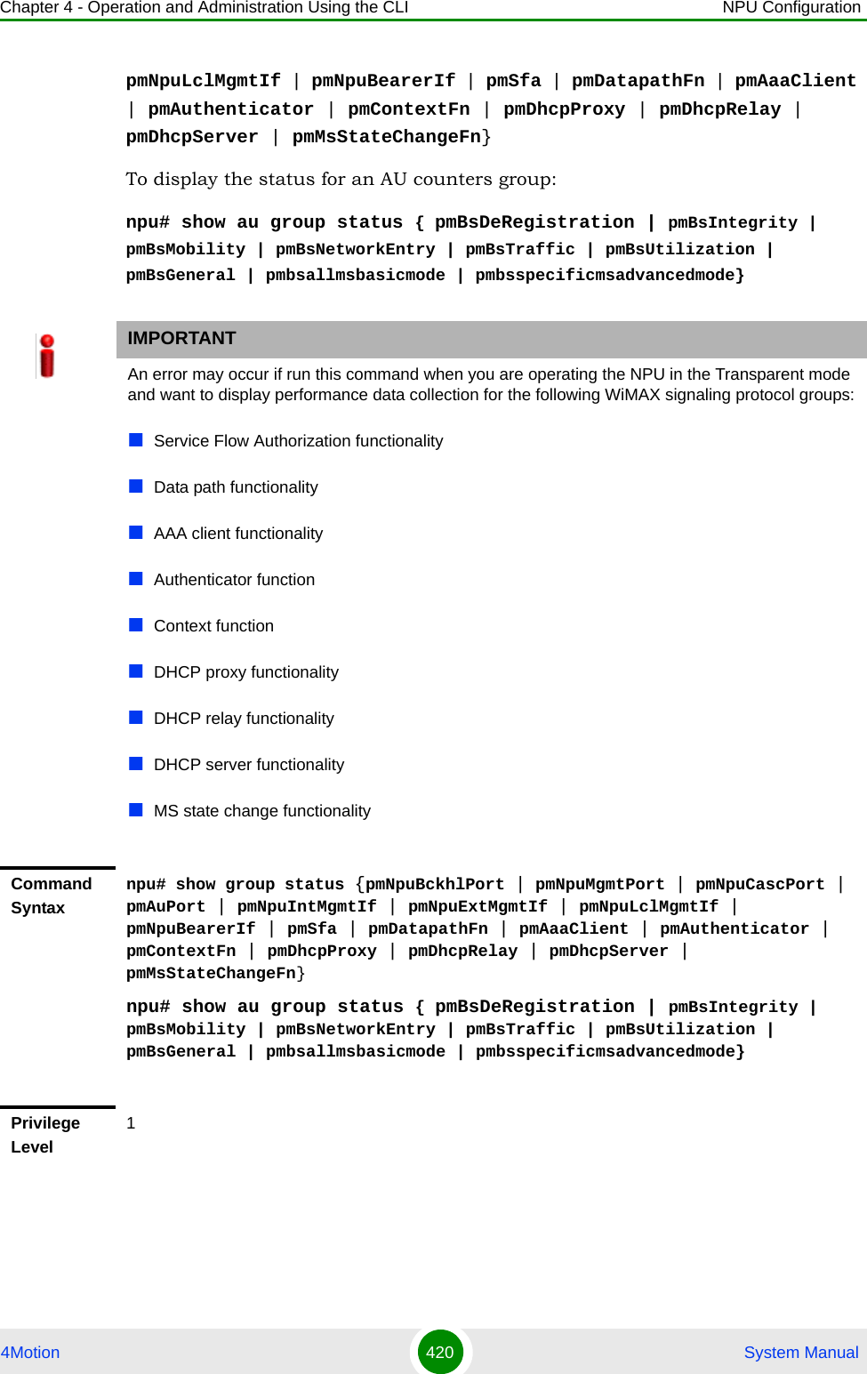
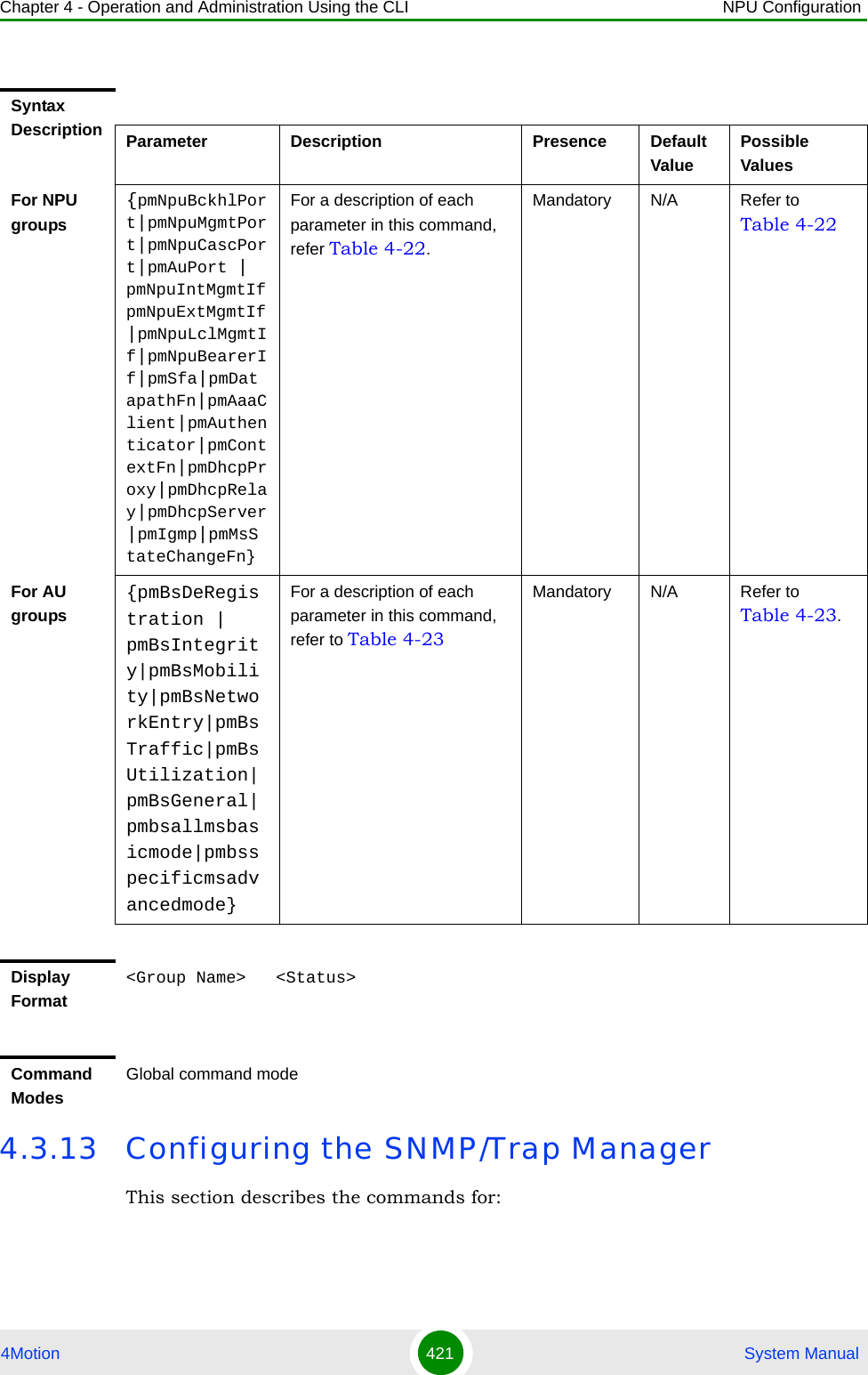
![Chapter 4 - Operation and Administration Using the CLI NPU Configuration4Motion 422 System Manual“Configuring the SNMP Manager” on page 422“Configuring the Trap Manager” on page 4244.3.13.1 Configuring the SNMP ManagerTo enable 4Motion configuration over SNMP, you are required to first configure the SNMP Manager. You can configure up to five SNMP Managers for the 4Motion system. This section describes the commands to be executed for:“Adding an SNMP Manager” on page 422“Deleting an Entry for the SNMP Manager” on page 423“Displaying Configuration Information for SNMP Managers” on page 4244.3.13.1.1 Adding an SNMP ManagerYou can configure upto five SNMP Managers. To add an SNMP Manager, run the following command:npu(config)# snmp-mgr [ReadCommunity <string>] [ReadWriteCommunity <string>]You can display configuration information for existing SNMP Managers. For details, refer Section 4.3.13.1.3.NOTEAn existing SNMP Manager entry cannot be modify. To modify the parameters of an SNMP Manager, delete the entry and add a new entry with the required parameters.IMPORTANTAn error may occur if you have specified:More than five entries for the SNMP Manager Duplicate entriesCommand Syntaxnpu(config)# snmp-mgr [ReadCommunity <string>] [ReadWriteCommunity <string>]Privilege Level10](https://usermanual.wiki/Alvarion-Technologies/BMAX-OR-25.Manual-2/User-Guide-1114030-Page-326.png)
![Chapter 4 - Operation and Administration Using the CLI NPU Configuration4Motion 423 System Manual4.3.13.1.2 Deleting an Entry for the SNMP ManagerTo delete an SNMP Manager entry, run the following command:npu(config)# no snmp-mgr index <integer>Syntax Description Parameter Description Presence Default ValuePossible Values[ReadCommunity <string>]IThe SNMP Read Community string allowing execution of SNMP Get operations.Optional public String (up to 10 characters and case-sensitive)[ReadWriteCommunity <string>]The SNMP Read/Write Community string allowing execution of SNMP Set and Get operations.Optional private String (up to 10 characters and case-sensitive)Command ModesGlobal configuration modeIMPORTANTAn error may occur if you provide an incorrect index number for the SNMP Manager to be deleted. To display the index numbers for configured SNMP Managers, refer Section 4.3.13.1.3.Command Syntaxnpu(config)# no snmp-mgr index <integer>Privilege Level10Syntax Description Parameter Description Presence Default ValuePossible Values<integer> Indicates the index number of the SNMP Manager to be deleted. Should be an index of an existing SNMP Manager.Mandatory N/A 1-5](https://usermanual.wiki/Alvarion-Technologies/BMAX-OR-25.Manual-2/User-Guide-1114030-Page-327.png)
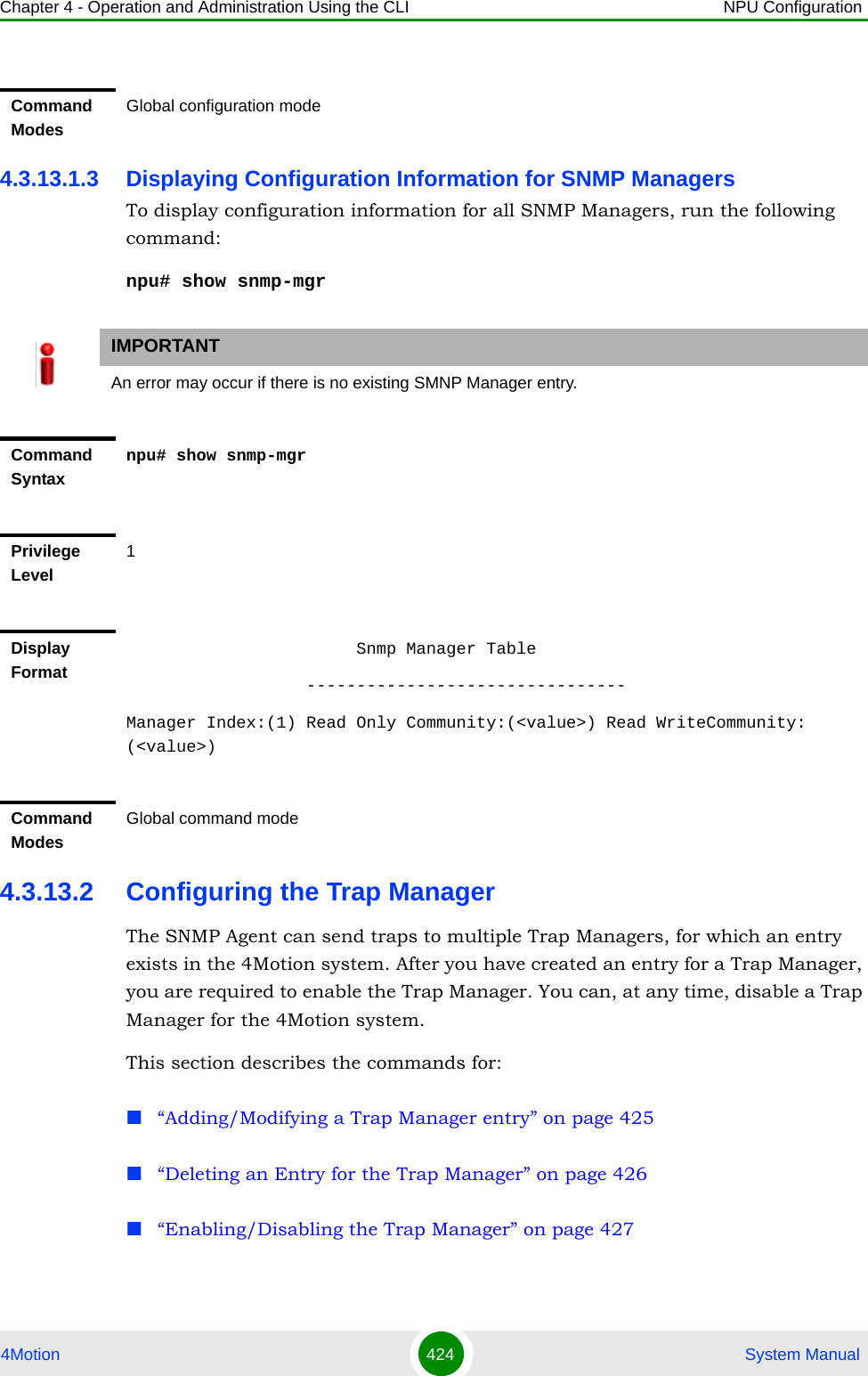
![Chapter 4 - Operation and Administration Using the CLI NPU Configuration4Motion 425 System Manual“Displaying Configuration Information for Trap Managers” on page 427“Displaying the Trap Rate Limit” on page 4284.3.13.2.1 Adding/Modifying a Trap Manager entryYou can configure up to five Trap Manager entries for the 4Motion system. To add a Trap Manager entry, or to modify an existing entry, run the following command:npu(config)# trap-mgr ip-source <ip_addr> [Port <(0-65535)>] [TrapCommunity <string>] [EnableFlag <integer(1 for enable, 2 for disable)>]You can view configuration information for existing Trap Managers. For details, refer Section 4.3.13.2.4.IMPORTANTAn error may occur if :You have specified invalid values for the IP address, Trap Community or port.The IP address is already configured for another Trap Manager.You are trying to create more than five Trap Managers. (You can configure up to five Trap Managers for the 4Motion system.Command Syntaxnpu(config)# trap-mgr ip-source <ip_addr> [Port <(0-65535)>] [TrapCommunity <string>] [EnableFlag <integer(1 for enable, 2 for disable)>]Privilege Level10Syntax Description Parameter Description Presence Default ValuePossible Values<ip_addr> Indicates the IP address of the Trap Manager to be added or modified.Must be unique (the same IP address cannot be assigned to more than one Manager)Mandatory N/A Valid IP address](https://usermanual.wiki/Alvarion-Technologies/BMAX-OR-25.Manual-2/User-Guide-1114030-Page-329.png)
![Chapter 4 - Operation and Administration Using the CLI NPU Configuration4Motion 426 System Manual4.3.13.2.2 Deleting an Entry for the Trap ManagerTo delete a Trap Manager, run the following command:npu(config)# no trap-mgr ip-source <ip_addr>[Port <(0-65535)>]Indicates the port number on which the Trap Manager will listen for messages from the Agent.Optional 162 0-65535[TrapCommunity <string>] Indicates the name of the community of the Trap Manager. Optional public String (up to 10 characters and case-sensitive)[EnableFlag<integer(1 for enable, 2 for disable)>] Indicates whether traps sending to the Trap Manager is to be enabled. or disabledOptional 1 1: Indicates enable2 Indicates disableCommand ModesGlobal configuration modeIMPORTANTAn error may occur if the IP address you have specifed does not exist.Command Syntaxnpu(config)# no trap-mgr ip-source <ip_addr>Privilege Level10Syntax Description Parameter Description Presence Default ValuePossible Values<ip_addr> Indicates the IP address of the Trap Manager to be deleted.Mandatory N/A Valid IP addressCommand ModesGlobal configuration mode](https://usermanual.wiki/Alvarion-Technologies/BMAX-OR-25.Manual-2/User-Guide-1114030-Page-330.png)
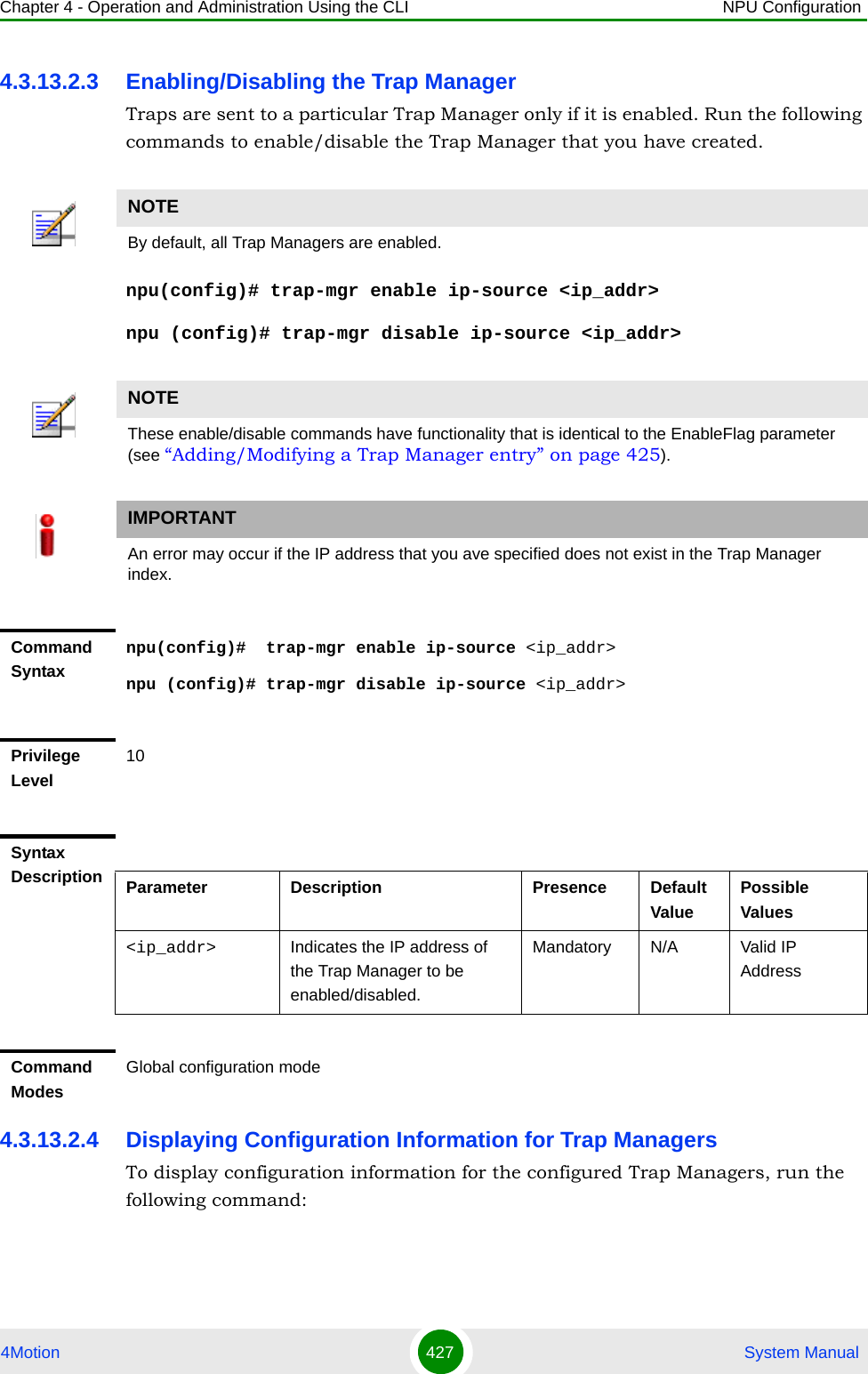
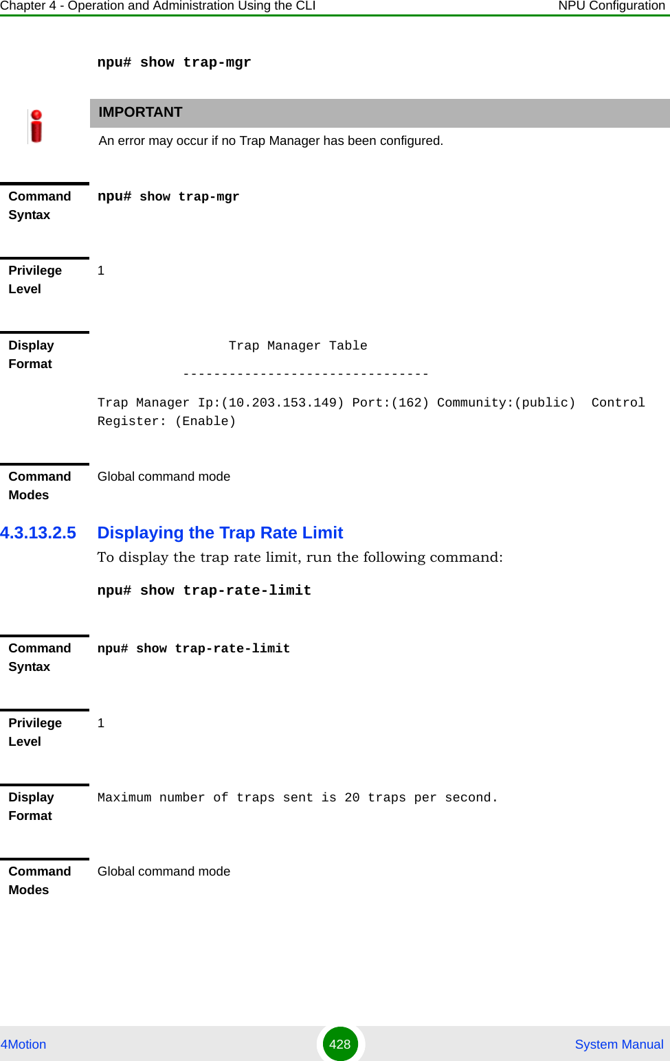
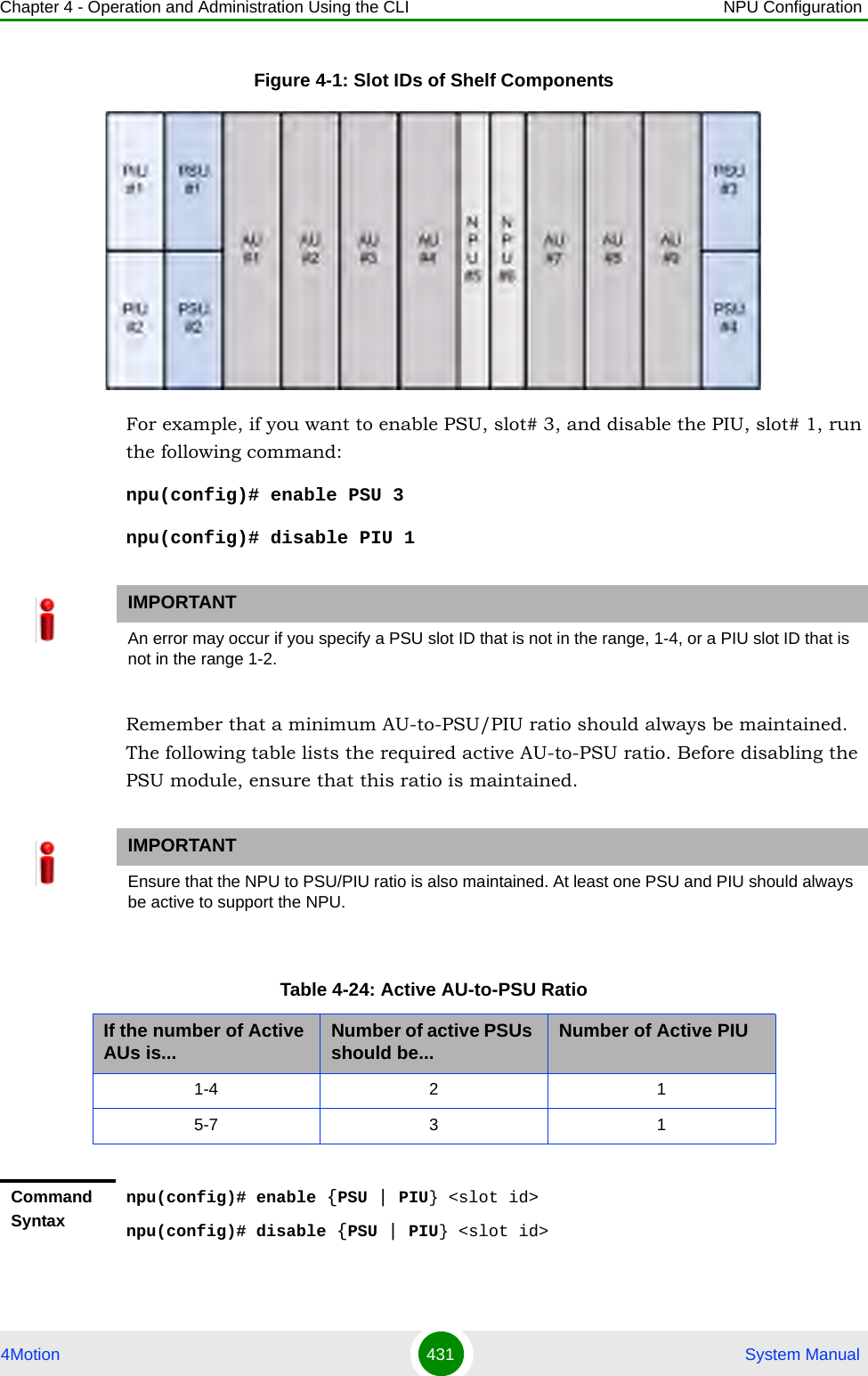
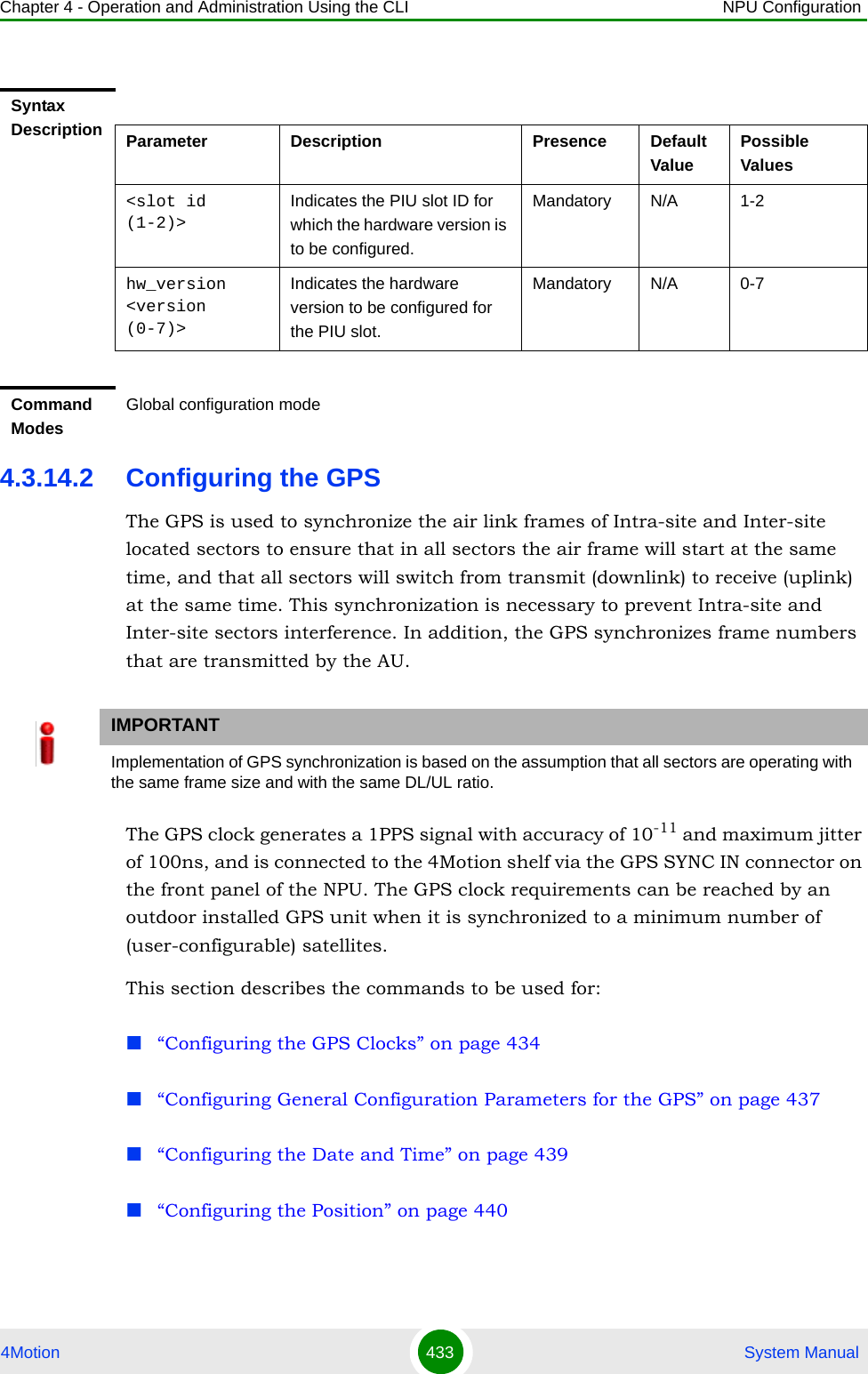
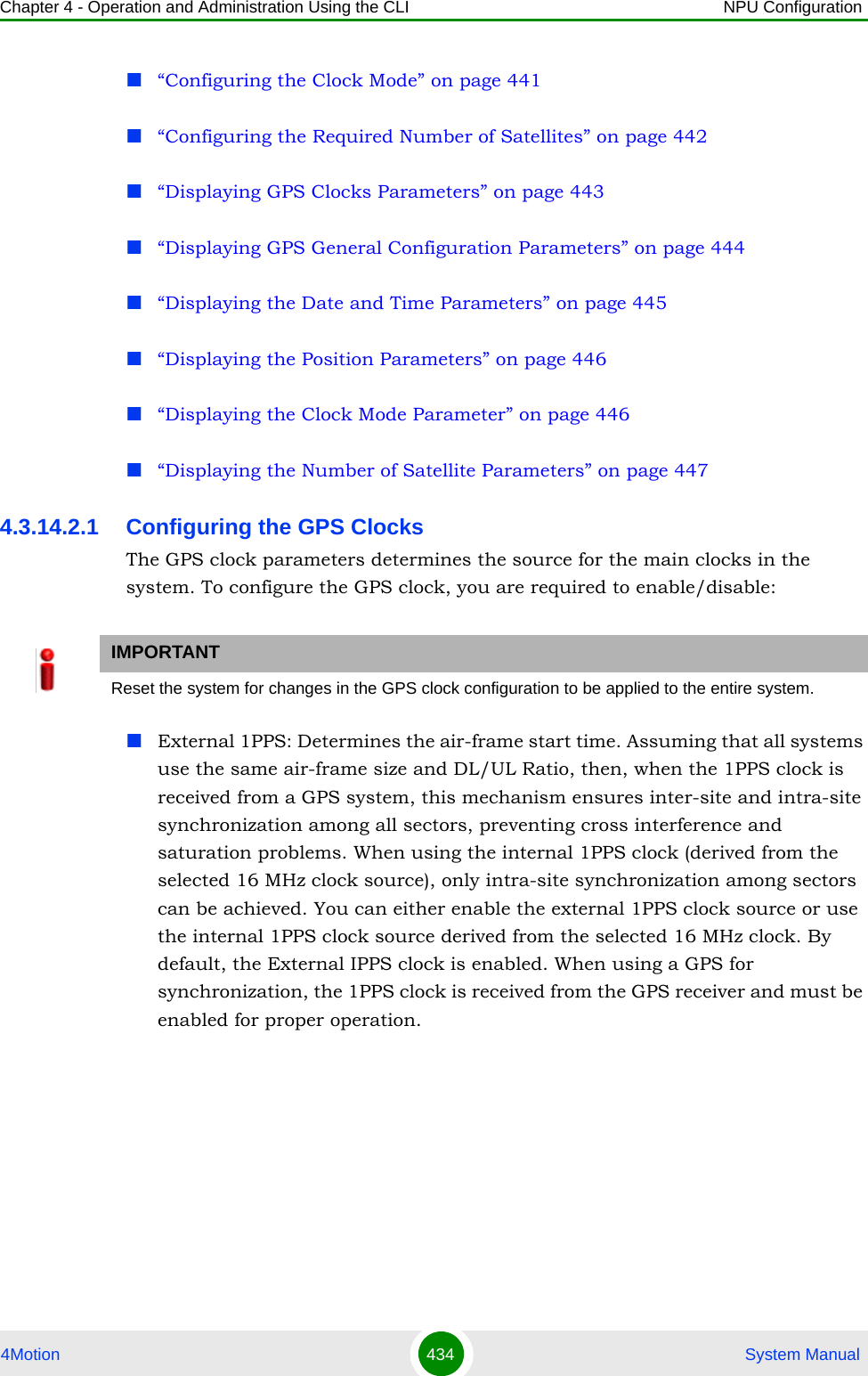
![Chapter 4 - Operation and Administration Using the CLI NPU Configuration4Motion 435 System ManualExternal 16MHz: Generates all the main clocking signals in the system, including the internal 1PPS clock. Using an external, accurate 16 MHz clock source will enable better hold-over of the 1PPS clock upon temporary loss (or reduced reliability when receiving less than 4 satellites) of the external 1PPS clock. This will allow a longer time of continued operation before appearance of interferences due to clock drifts among BSs. You can either enable the external 16 MHz clock source or use the internal 16 MHz clock source. By default, the external 16MHz clock is disabled. In the current release MHz clock must be disabled.To configure the GPS clock, run the following command:npu(config)# set clock ([ External1PPS {Enable | Disable} ] [ External16MHz {Enable | Disable} ])For example, to configure the internal 1PPS clock at the NPU to synchronize the air frames for inter-site and intra-site sectors:npu(config)# set clock External1PPS DisableNOTEIf the external 1PPS GPS clock is enabled:The concatenated slave NPU 16Mhz created from local 16MHz TCXO/OCXO at the NPU provides holdover when the GPS loses synchronization with its satellites.Configure the GPS parameters listed in section, Section 4.3.14.2.2.Command Syntaxnpu(config)# set clock ([External1PPS {Enable | Disable}] [External16MHz {Enable | Disable}])Privilege Level10](https://usermanual.wiki/Alvarion-Technologies/BMAX-OR-25.Manual-2/User-Guide-1114030-Page-339.png)
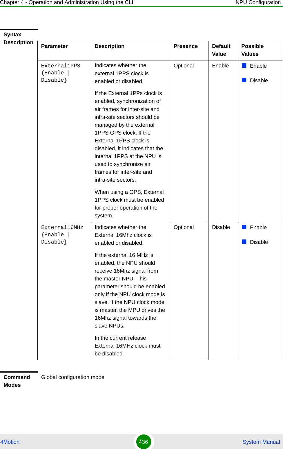
![Chapter 4 - Operation and Administration Using the CLI NPU Configuration4Motion 437 System Manual4.3.14.2.2 Configuring General Configuration Parameters for the GPSThe GPS general configuration parameters determine how the GPS should function with respect to the 4Motion system. Depending upon the values defined for these parameters, you can configure the GPS clock (external 1PPS and 16MHz), and the UTC time. Run the following command to configure the global configuration parameters for the GPS:npu(config)# gps config ( [Type {Trimble | None}] [AdaptorRequired {Yes | No}][HoldoverPassedTout <expiry_interval(0-2880)>] [HoldoverPassTxOperationStop {True | False}][AlmanacUsableTime <expiry_interval(0-4320)>] [EphemerisUsableTime <expiry_interval(0-168)>] [IntervalToReadGPSTime{Hourly | Daily | Monthly | Yearly}] [TimeToReadGPSTime <HH:MM:SS,DD/MM>]))IMPORTANTSkip this section if you have selected the internal 1PPS clock. For more information about configuring the GPS clock, refer Section 4.3.14.2.1.IMPORTANTAn error may occur if:Time to read GPS time is not in valid format. Correct format is hh:mm:ss, dd/mm: Minute and Second should be within range of 0 to 60, Hour should be within the range of 0 to 23, days should be in the range 1 to 31 and Month should be within the range of 1 to 12, also day should be valid in accodance with month.Command Syntaxnpu(config)# gps config gps config ( [Type {Trimble | None}] [AdaptorRequired {Yes | No}][HoldoverPassedTout <expiry_interval(0-2880)>] [HoldoverPassTxOperationStop {True | False}][AlmanacUsableTime <expiry_interval(0-4320)>] [EphemerisUsableTime <expiry_interval(0-168)>] [IntervalToReadGPSTime{Hourly | Daily | Monthly | Yearly}] [TimeToReadGPSTime <HH:MM:SS,DD/MM>]))Privilege Level10Syntax DescriptionParameter Description Presence Default ValuePossible Values](https://usermanual.wiki/Alvarion-Technologies/BMAX-OR-25.Manual-2/User-Guide-1114030-Page-341.png)
![Chapter 4 - Operation and Administration Using the CLI NPU Configuration4Motion 438 System ManualType {Trimble | None}]Indicates the type of GPS connected to 4Motion.Optional Trimble TrimbleNone[AdaptorRequired {Yes | No}]Indicates whether a GPS adaptor is required. The NPU can be connected to an extenal GPS adaptor that allows the NPU to connect to multiple GPS interfaces/1PPS /16Mhz clocks. In the current release a GPS adapter is not supported.Optional No YesNo[HoldoverTimeout <expiry_interval (0-2880)>]Indicates the period, in minutes, for which the NPU provides holdover when the GPS loses synchronization with its satellites. Optional 720 0 - 2880[HoldoverPassTxOperationStop{True | False}]Indicates whether the AU modules should stop data transmission if the GPS loses synchronization with its satellites and the holdover timeout has occurred.Optional True TrueFalse[AlmanacUsableTime <expiry-interval(0-4320)>]Indicates the maximum period, in hours, for which the Almanac time is valid when the GPS is reset.Optional 720 0-4320[EphemerisUsableTime <expiry-interval(0-168)>]Indicates the maximum period, in hours, for which the Ephemeris time is valid when the GPS is reset.Optional 4 0-168[IntervalToReadGPSTime {Hourly | Daily | Monthly | Yearly}]Indicates the interval after which the NPU should obtain the GPS time for frame synchronization, and send it to the AU.Optional Daily HourlyDailyMonthlyYearly[TimeToReadGPSTime <HH:MM:SS,DD/MM>]Indicates the time when the NPU should obtain the GPS time for frame synchronization. .Optional 04:05 HH:MM:SS,DD/MM](https://usermanual.wiki/Alvarion-Technologies/BMAX-OR-25.Manual-2/User-Guide-1114030-Page-342.png)
![Chapter 4 - Operation and Administration Using the CLI NPU Configuration4Motion 439 System Manual4.3.14.2.3 Configuring the Date and TimeThe UTC time is used to configure the following:Local time: Differs from the UTC time with respect to the value you have specified for the localUTCDiff and DST parameters. The local time is equal to the sum of the UTC time, the value of the localUTCDiff parameter (local offset from UTC time) and DST (daylight saving time offset). For more information about configuring this parameter, “Configuring the GPS Clocks” on page 434. You can use the CLI to display the current local time. For details, refer the section, “Displaying the Date and Time Parameters” on page 445.System time: Refers to the operating system (kernel) time that is identical to the UTC time when the system boots up. The system time is updated every hour with the time received from the GPS receiver.Real Time Clock (RTC) time: Refers to the time maintained by the board’s hardware clock. By default, the RTC time is set to 1st January, 1970. The RTC time is updated every hour with the UTC time that is received from the GPS receiver or that you have configured from the CLI. The RTC time is used for creating the timestamp for log and trace messages, performance data collection files, and for managing the interval after which a backup of the configuration file should be maintained and performance data should be collected.Execute the following command to configure the date and time parameters. If the GPS is synchronized to its satellites and is connected to 4Motion, the UTC time is provided by the GPS. Otherwise the UTC time that you configure is used instead.To configure the date and time parameters, run the following command:npu(config)# set date [UTC <HH:MM:SS,DD/MM/YYYY>] [LocalUTCDiff <+/-HH:MM>] [DST <(0-2)>]Command ModesGlobal configuration modeIMPORTANTAn error may occur if :1) UTC time is not in the valid format i.e. hh: mm: ss, dd/mm/yyyy. 2) Local UTCDiff is not valid format i.e. +/-hh:mm3) Local UTC Diff is out of the range between -12 to +13 or it is not in steps of 30 minutes.4) DST is out of range i.e between 0 to 2](https://usermanual.wiki/Alvarion-Technologies/BMAX-OR-25.Manual-2/User-Guide-1114030-Page-343.png)
![Chapter 4 - Operation and Administration Using the CLI NPU Configuration4Motion 440 System Manual4.3.14.2.4 Configuring the PositionThe position configuration enables setting the location’s parameters when GPS is not used (Type=None).To configure the position parameters, run the following command:npu(config)# set position ([Latitude <xxx.xxx,N/S>] [Longitude <xxx.xxx,E/W>] [Altitude (-300.0 - 9000.0)])Command Syntaxnpu(config)# set date [UTC <HH:MM:SS,DD/MM/YYYY>] [LocalUTCDiff <+/-HH:MM>] [DST <(0-2)>]Privilege Level10Syntax Description Parameter Description Presence Default ValuePossible ValuesUTC <HH:MM:SS,DD/MM/YYYY>Indicates the UTC time to be used for 4Motion if not available from GPS.Mandatory N/A Use the format:HH:MM: SS, DD/MM/YYYYLocalUTCDiff <+/-HH:MM>The local offset from UTC Optional +00:00 +/-HH:MMHH: -12 to +13MM: 00 or 30DST <(0-2)> Daylight Saving Time offset of the local clockOptional 0 0-2Command ModesGlobal configuration modeIMPORTANTAn error may occur if :1) Latitude, longitude and altitude are configured while GPS type is not "None".2) Latitude is not in valid format i.e. lll.mmm,a where a is either N or S3) Longitude is not in valid format i.e. lll.mmm,a where a is either E or W.4) Altitude is not in valid range i.e. +-300.0 to 9000.0.](https://usermanual.wiki/Alvarion-Technologies/BMAX-OR-25.Manual-2/User-Guide-1114030-Page-344.png)
![Chapter 4 - Operation and Administration Using the CLI NPU Configuration4Motion 441 System Manual4.3.14.2.5 Configuring the Clock ModeThe Clock Mode parameter enables defining the functionality of the NPU when GPS chaining is used. In the current release GPS chaining is not supported and the clock mode must be set to Master.To configure the clock mode parameter, run the following command:npu(config)# set npu ClockMode {Master | Redundant | Slave}Command Syntaxnpu(config)# set position ([Latitude <xxx.xxx,N/S>] [Longitude <xxx.xxx,E/W>] [Altitude (-300.0 - 9000.0)])Privilege Level10Syntax Description Parameter Description Presence Default ValuePossible ValuesLatitude <xxx.xxx,N/S>Indicates the latitude where the 4Motion shelf is currently positioned. Configure only if GPS Type is None.Optional 000.000.N Use the format, Ill.mmm.a (where lll.mmm is in degrees and the value of a is either N or S)Longitude <xxx.xxx,E/W>Indicates the longitude where the 4Motion shelf is currently positioned. Configure only if GPS Type is None.Optional 000.000.E Use the format, Ill.mmm.a (where ll.mmm is in degrees and the value of a is either E or W)Altitude (-300.0 - 9000.0)])Indicates the altitude (in meters) where the 4Motion shelf is currently positioned. Configure only if GPS Type is None.Optional 0.0 -300.0 to 9000.0Command ModesGlobal configuration mode](https://usermanual.wiki/Alvarion-Technologies/BMAX-OR-25.Manual-2/User-Guide-1114030-Page-345.png)
![Chapter 4 - Operation and Administration Using the CLI NPU Configuration4Motion 442 System Manual4.3.14.2.6 Configuring the Required Number of SatellitesThe satellite parameter enables configured the minimum number of satellites required for maintaining synchronization and for renewing synchronization after synchronization loss.To configure the satellite parameters, run the following command:npu(config)# set satellite ([MinNumOfSatForHoldoverReturn <range (1-12)>] [MaxNumOfSatBeforeSyncLoss <range (0-11)>])IMPORTANTAn error may occur if setting to any option other than Master because current release supports only the Master option.Command Syntaxnpu(config)# set npu ClockMode {Master | Redundant | Slave}Privilege Level10Syntax Description Parameter Description Presence Default ValuePossible Valuesnpu ClockMode {Master | Redundant | Slave}Indicates the clocks functionality of the NPU when GPS chaining is used. GPS chaining is not supportyed in current release and this parameter must be set to its default value of Master.Optional Master Master(other options not supported in current release)Command ModesGlobal configuration modeIMPORTANT1) An error can occur while configuring MinNumOfSatForHoldoverReturn if Minimum number of satellite for holdover return is less than Maximum number of satellite before synchronization loss.2) An error can occur while configuring MaxNumOfSatBeforeSyncLoss if Maximum number of satellite before synchronization is more than Minimum number of satellite for holdover return.](https://usermanual.wiki/Alvarion-Technologies/BMAX-OR-25.Manual-2/User-Guide-1114030-Page-346.png)
![Chapter 4 - Operation and Administration Using the CLI NPU Configuration4Motion 443 System Manual4.3.14.2.7 Displaying GPS Clocks ParametersTo display the GPS clock configuration parameters, run the following command:npu# show clock status [{CurrentExternal1PPS | ConfiguredExternal1PPS | CurrentExtrnal16MHz | ConfiguredExternal16MHz}]Command Syntaxnpu(config)# set satellite ([MinNumOfSatForHoldoverReturn <range (1-12)>] [MaxNumOfSatBeforeSyncLoss <range (0-11)>]Privilege Level10Syntax Description Parameter Description Presence Default ValuePossible ValuesMinNumOfSatForHoldoverReturn <range (1-12)>Indicates the minimum number of satellites that should be received for resuming synchronization (exiting holdover status) after loss of synchronization.Optional 2 1-12MaxNumOfSatBeforeSyncLoss <range (0-11)>Indicates the minimum number of satellites required for maintaining synchronization.Optional 1 0-11Command ModesGlobal configuration modeCommand Syntaxnpu# show clock status [{CurrentExternal1PPS | ConfiguredExternal1PPS | CurrentExtrnal16MHz | ConfiguredExternal16MHz}Privilege Level1](https://usermanual.wiki/Alvarion-Technologies/BMAX-OR-25.Manual-2/User-Guide-1114030-Page-347.png)
![Chapter 4 - Operation and Administration Using the CLI NPU Configuration4Motion 444 System Manual4.3.14.2.8 Displaying GPS General Configuration ParametersTo display the GPS general configuration parameters, run the following command:npu# show gps config [{ Type | SoftwareVersion [{ Navigation | Signal }] | AdaptorRequired | HoldoverPassedTout | HoldoverPassTxOperationStop | AlmanacUsableTime | EphemerisUsableTime | IntervalToReadGPSTime | TimeToReadGPSTime} ]Syntax DescriptionFor a detailed description of each parameter in this command, refer the section, “Configuring the GPS Clocks” on page 434.Both Current and Configured values for each clock are provided (the parameters are applied after reset)Display FormatConfigured External 1PPS Status :Enable/ DisableCurrent External 1PPS Status :Enable/ DisableConfigured External 16MHz Status :Enable/ DisableCurrent External 16MHz Status :Enable/ DisableCommand ModesGlobal command modeCommand Syntaxnpu# show gps config [{ Type | SoftwareVersion [{ Navigation | Signal }] | AdaptorRequired | HoldoverPassedTout | HoldoverPassTxOperationStop | AlmanacUsableTime | EphemerisUsableTime | IntervalToReadGPSTime | TimeToReadGPSTime} ]Privilege Level1Syntax DescriptionFor a detailed description of each parameter in this command, refer the section, “Configuring General Configuration Parameters for the GPS” on page 437.](https://usermanual.wiki/Alvarion-Technologies/BMAX-OR-25.Manual-2/User-Guide-1114030-Page-348.png)
![Chapter 4 - Operation and Administration Using the CLI NPU Configuration4Motion 445 System ManualIn addition to the configuration parameters, the SW Versions of the GPS Navigation and Signal Processors are also displayed (if available).4.3.14.2.9 Displaying the Date and Time ParametersTo display the current date parameters, run the following command:npu# show date [{Local | UTC | LocalUTCDiff | DST}]Display FormatConfigured GPS Type :GPS Navigation Processor SW Version :GPS Signal Processor SW version :Adaptor Required :Holdover Timeout :HoldoverPassedTxOperationStop :Almanac Usable Time :Ephemeris Usable Time :Interval To Read Gps Time :Time To Read Gps Time :Command ModesGlobal command modeCommand Syntaxnpu# show date [{Local | UTC | LocalUTCDiff | DST}]Privilege Level1Syntax DescriptionFor a detailed description of each parameter in this command, refer the section, “Configuring the Date and Time” on page 439.Display FormatLocal Time :UTC Time :Local UTC Offset :Daylight Saving Time :](https://usermanual.wiki/Alvarion-Technologies/BMAX-OR-25.Manual-2/User-Guide-1114030-Page-349.png)
![Chapter 4 - Operation and Administration Using the CLI NPU Configuration4Motion 446 System ManualIn addition to the configurable parameters, the calculated Local Time is also displayed.4.3.14.2.10 Displaying the Position ParametersTo display the current position parameters, run the following command:npu# show position [{Latitude | Longitude | Altitude}]4.3.14.2.11 Displaying the Clock Mode ParameterTo display the current clock mode parameter, run the following command:npu# show npu clock modeCommand ModesGlobal command modeCommand Syntaxnpu# show position [{Latitude | Longitude | Altitude}]Privilege Level1Syntax DescriptionFor a detailed description of each parameter in this command, refer the section, “Configuring the Position” on page 440.Display FormatLatitude :Longitude :Altitude :Command ModesGlobal command modeCommand Syntaxnpu# show npu clock modePrivilege Level1](https://usermanual.wiki/Alvarion-Technologies/BMAX-OR-25.Manual-2/User-Guide-1114030-Page-350.png)
![Chapter 4 - Operation and Administration Using the CLI NPU Configuration4Motion 447 System Manual4.3.14.2.12 Displaying the Number of Satellite ParametersTo display the current satellite parameters, run the following command:npu# show satellite [{MinNumOfSatForHoldoverReturn | MaxNumOfSatBeforeSyncLoss | NumOfSatelliteAvailable}]In addition to the configurable parameters, the current number of satellites acquired by the GPS receiver is also displayed.4.3.14.3 Managing Power Feeders ConfigurationThe Power Feeder configuration enables specifying the AU port connected to each Power Feeder port.Syntax DescriptionFor a detailed description of the parameter in this command, refer the section, “Configuring the Clock Mode” on page 441.Display FormatNPU Clock Mode : MasterCommand ModesGlobal command modeCommand Syntaxnpu# show satellite [{MinNumOfSatForHoldoverReturn | MaxNumOfSatBeforeSyncLoss | NumOfSatelliteAvailable}]Privilege Level1Syntax DescriptionFor a detailed description of each parameter in this command, refer the section, “Configuring the Required Number of Satellites” on page 442.Display FormatMax Satellites Before Sync Loss :Min Satellites For Holdover Return :Number of Satellites Acquired :Command ModesGlobal command mode](https://usermanual.wiki/Alvarion-Technologies/BMAX-OR-25.Manual-2/User-Guide-1114030-Page-351.png)
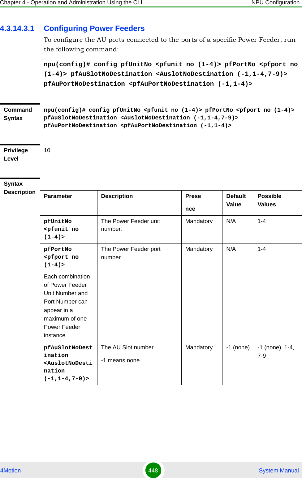
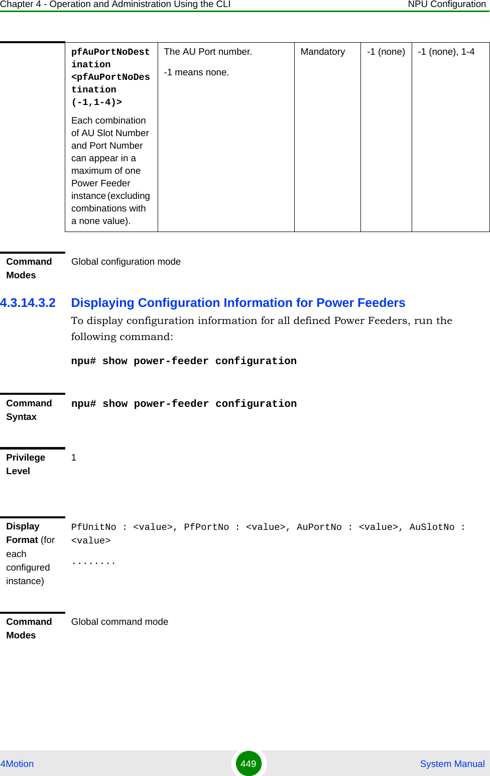
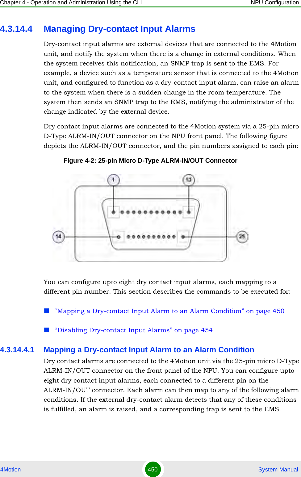
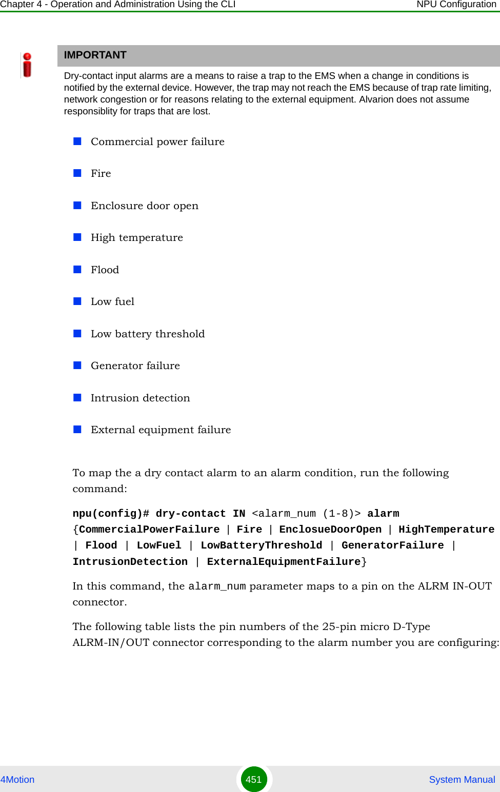
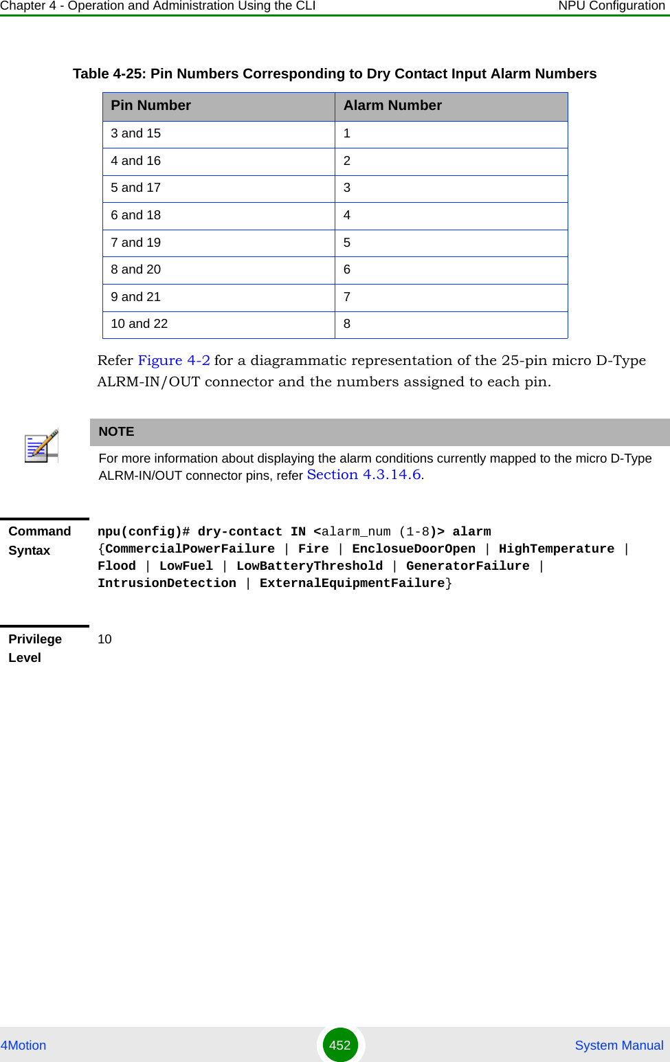
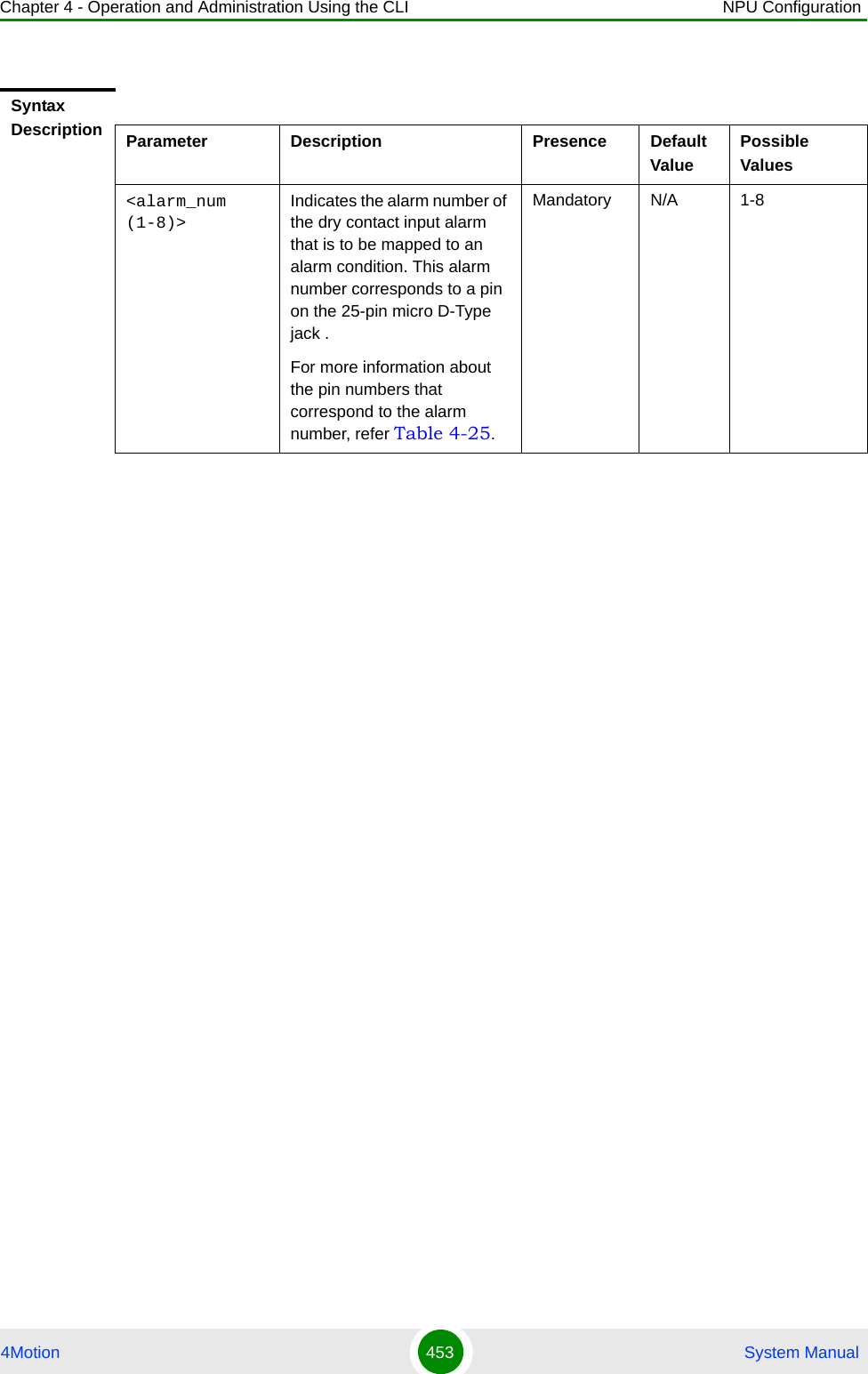
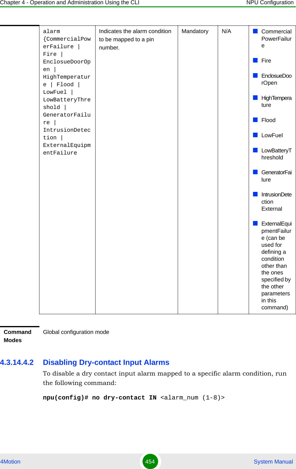
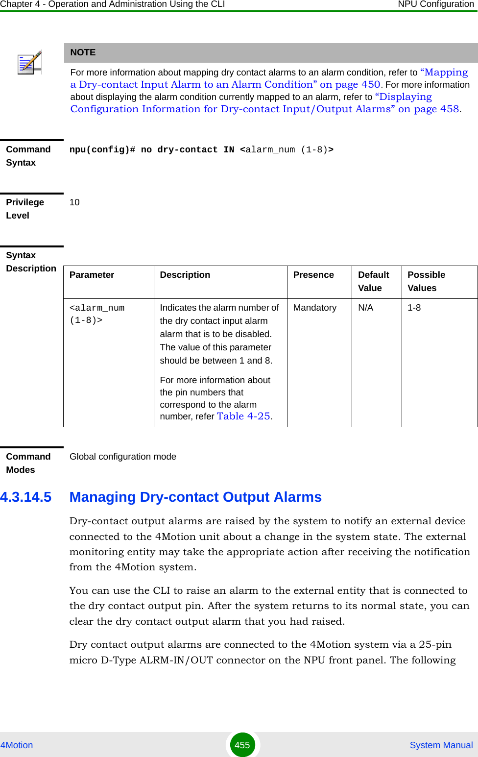
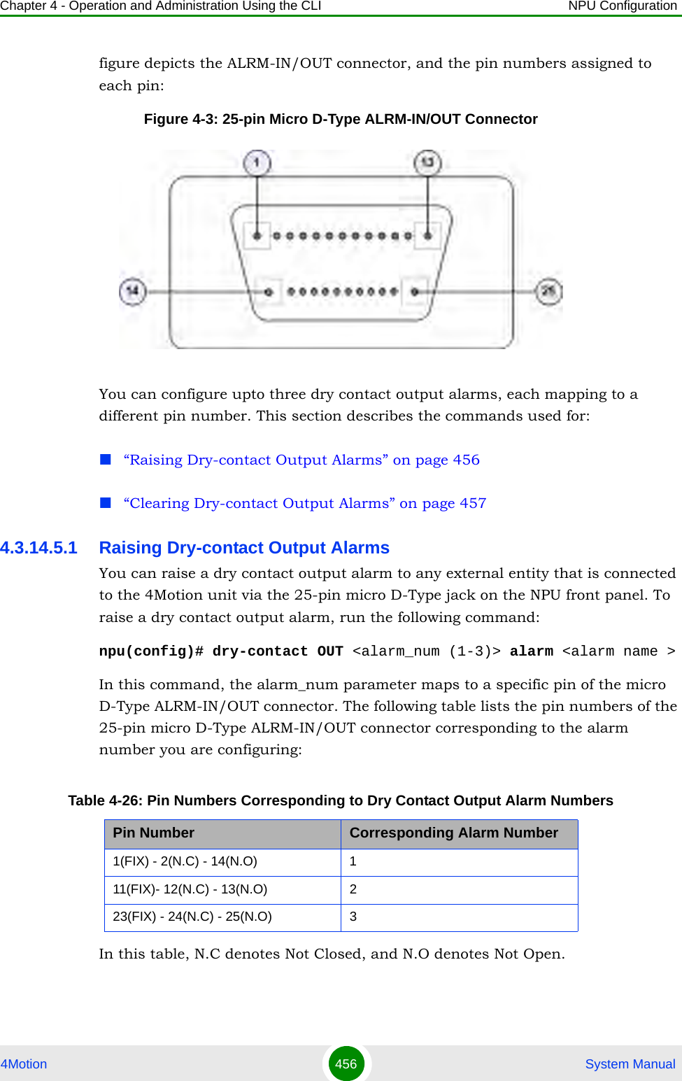
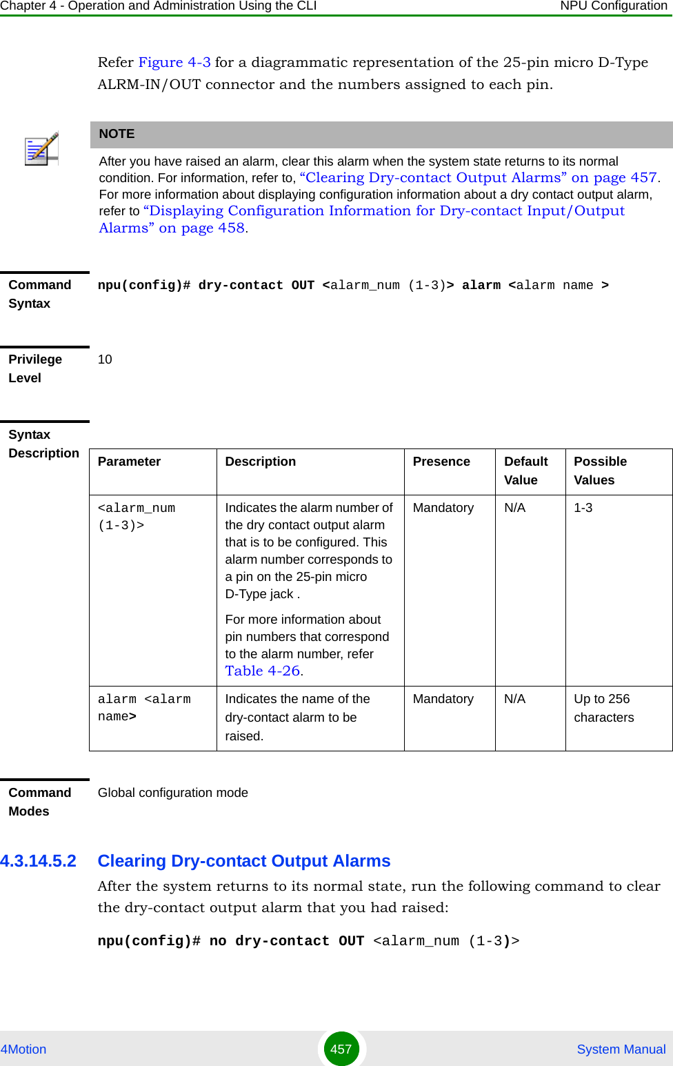
![Chapter 4 - Operation and Administration Using the CLI NPU Configuration4Motion 458 System ManualAfter you run this command, the alarm that you had raised is cleared. 4.3.14.6 Displaying Configuration Information for Dry-contact Input/Output AlarmsTo display configuration information for dry-contact input/output alarms, run the following command:npu# show dry-contact {IN | OUT} [<alarm_num>]If you want to display configuration information for input or output alarms, specify IN or OUT. You can also specify the pin number if you want to view configuration information for particular pin used for connecting an external device to the 4Motion unit.NOTENOTEFor more information about raising a dry contact ouput alarm, refer to “Raising Dry-contact Output Alarms” on page 456.Command Syntaxnpu(config)# no dry-contact OUT <alarm_num (1-3)>Privilege Level10Syntax Description Parameter Description Presence Default ValuePossible Values<alarm_num (1-3)>Indicates the alarm number of the dry contact output alarm alarm that is to be disabled. For more information about the pin numbers that correspond to the alarm number, refer Table 4-26.Mandatory N/A 1-3Command ModesGlobal configuration mode](https://usermanual.wiki/Alvarion-Technologies/BMAX-OR-25.Manual-2/User-Guide-1114030-Page-362.png)
![Chapter 4 - Operation and Administration Using the CLI NPU Configuration4Motion 459 System ManualFor example, run the following command if you want to display configuration information for the dry contact input alarm connected to the 4Motion unit via pin# 8 on the NPU panel:npu# show dry-contact IN 8If you want to display configuration information for all dry contact alarms, run the following command:npu# show dry-contactNOTEAn error may occur if you have specified an incorrect pin number for a particular input/output alarm. For more information about the correct pin-to-alarm number mapping, refer Table 4-25 and Table 4-26.Command Syntaxnpu# show dry-contact {IN | OUT} [<alarm_num>]Privilege Level1Syntax Description Parameter Description Presence Default ValuePossible Values{IN|OUT} Indicates whether configuration information is to be displayed for input or output alarms. If you do not specify this value, configuration information is displayed for all input and output alarms.Optional N/A INOUT](https://usermanual.wiki/Alvarion-Technologies/BMAX-OR-25.Manual-2/User-Guide-1114030-Page-363.png)
![Chapter 4 - Operation and Administration Using the CLI NPU Configuration4Motion 460 System Manual4.3.14.7 Configuring the Location Information for the 4Motion ShelfThe site location parameters provide general information on the site. Run the following command to configure the 4Motion shelf location information, such as the rack number and location:npu(config)# site {Name <name (32)> | Address <address(32)> | RackLocation <rack no. + position in rack (32)> | ContactPerson <name (32)> | AsnName <name (32)> |Region <area (32)> |ProductType BMAX_4M_Macro}For example, run the following command if you want to specify the site name:npu(config)# site name Site 12[<alarm_num>] Denotes the alarm number of the input or output alarm for which configuration information is to be displayed.Refer Figure 4-2 and Figure 4-3 for more information about the numbers assigned to the pins used for connecting dry contact alarms.Optional N/A 1-8 for input alarms1-3 for output alarmsDisplay FormatDry-Contact Input Alarm:AlarmNumber AlarmName InputBlocking<alarm num> <alarm name> <Yes or No>Dry-Contact Output Alarm:AlarmNumber AlarmStatus AlarmName<alarm num> <On or Off> <name>Command ModesGlobal command mode](https://usermanual.wiki/Alvarion-Technologies/BMAX-OR-25.Manual-2/User-Guide-1114030-Page-364.png)
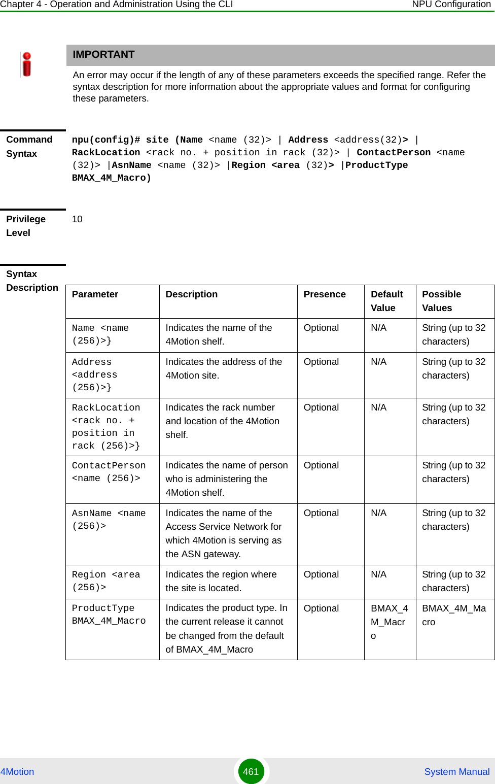
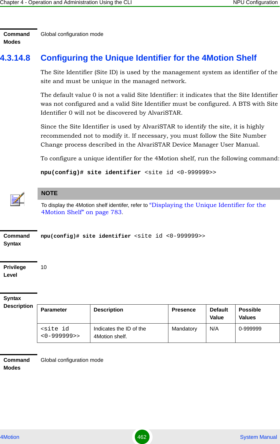
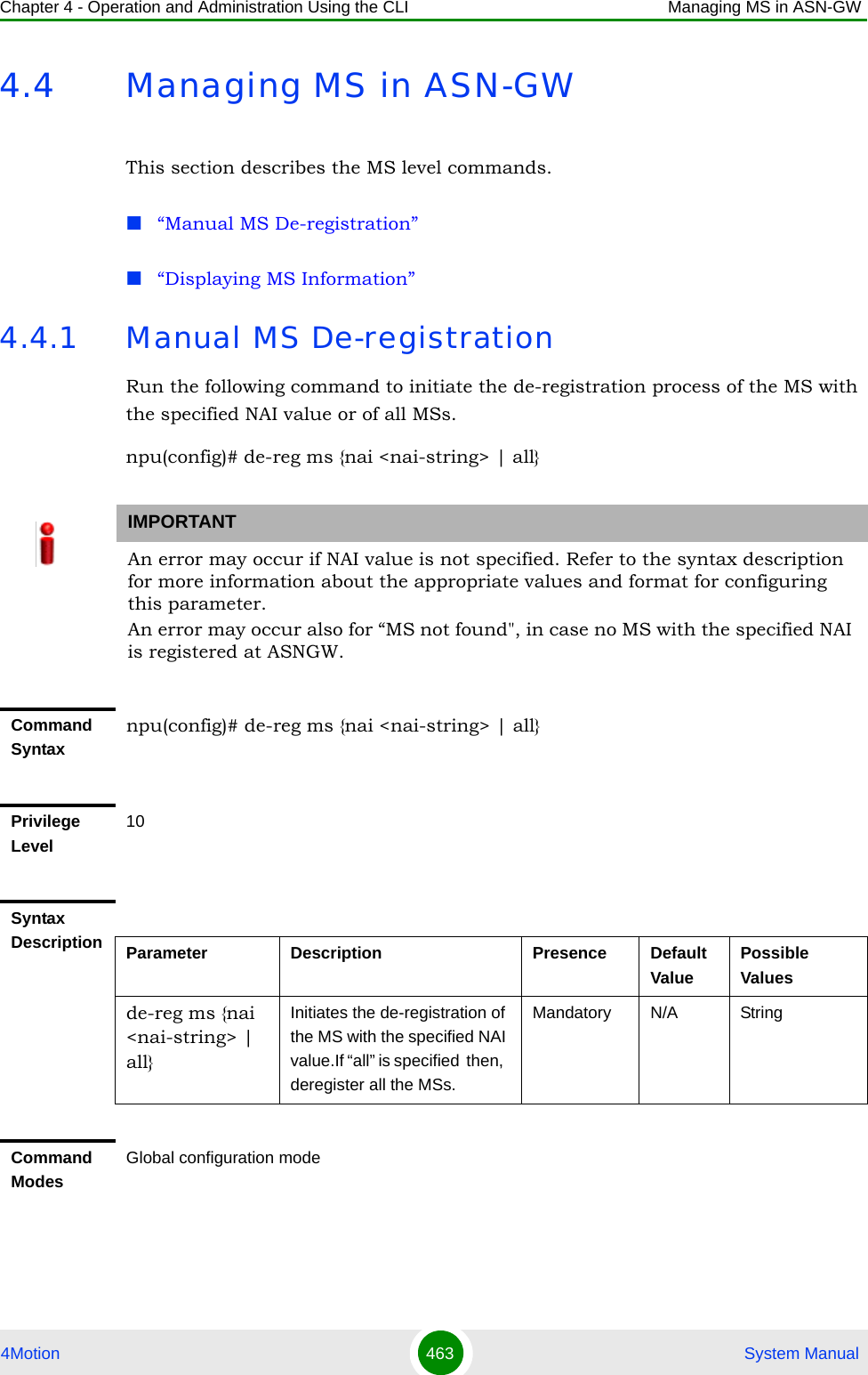
![Chapter 4 - Operation and Administration Using the CLI Managing MS in ASN-GW4Motion 464 System Manual4.4.2 Displaying MS InformationRun the following command to view the MS context information of the specified NAI/MSID. npu# show ms info [{nai|msid}<nai/msid string>]IMPORTANTAn error may occur if invalid NAI or invalid MSID is provided. Refer the syntax description for more information about the appropriate values and format for configuring this parameter.Command Syntaxnpu# show ms info [{nai|msid}<nai/msid string>]Privilege Level1Display FormatMS context Info: NAI = <value>MS ID = <value>Serving BS ID = Serving Flow ID1 = <value>Serving Flow GRE key = <value>Serving Flow Direction = <Uplink | Downlink>MS Flow Service Group IP = <value>|Serving Flow IDn = <value>Serving Flow GRE key = <value>Serving Flow Direction = <Uplink | Downlink>MS Flow Service Group IP = <value>Command ModesGlobal command mode](https://usermanual.wiki/Alvarion-Technologies/BMAX-OR-25.Manual-2/User-Guide-1114030-Page-368.png)
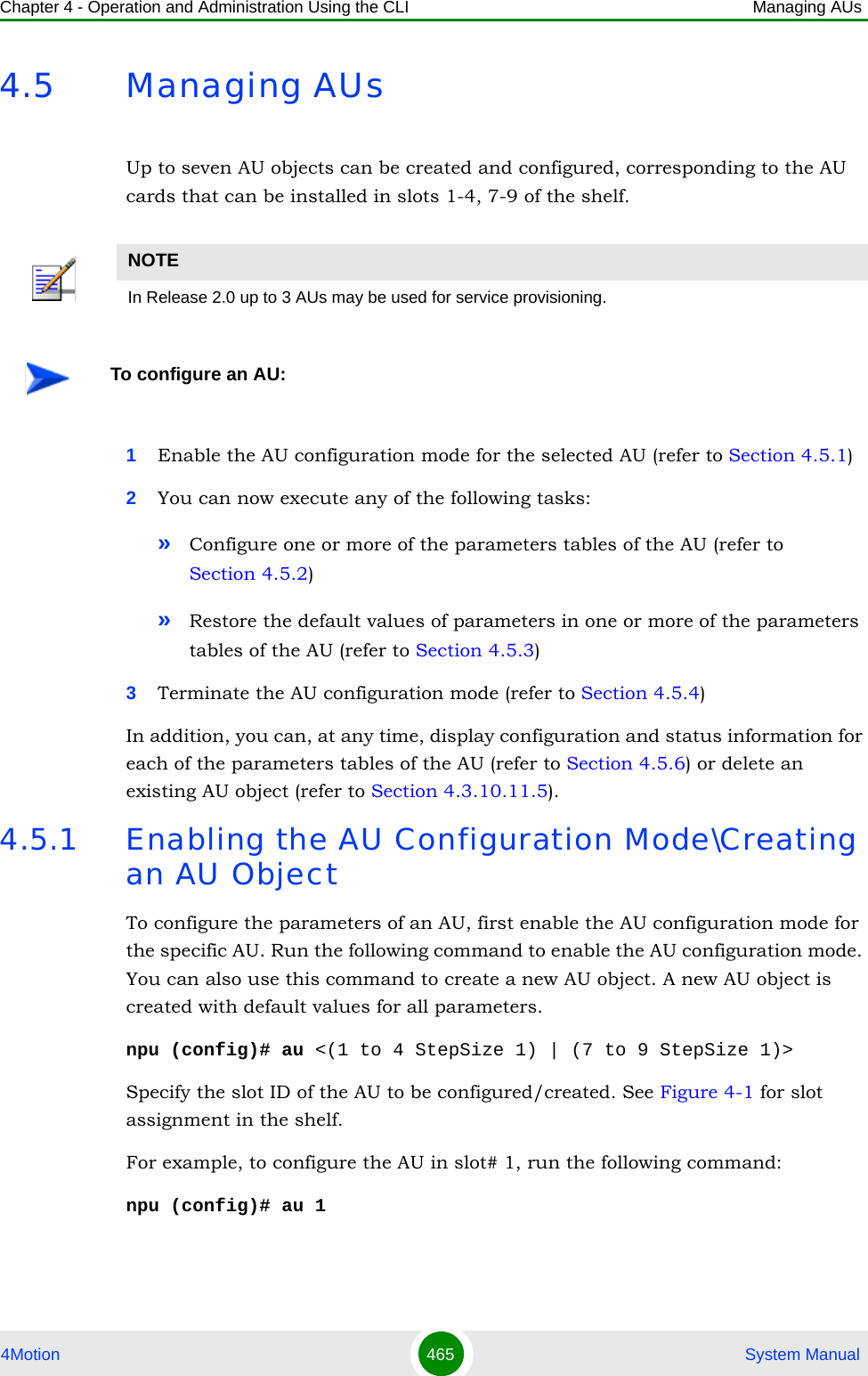
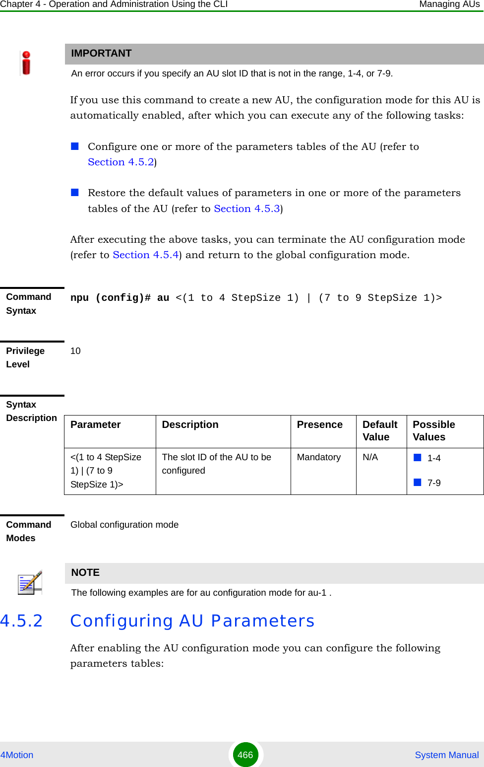
![Chapter 4 - Operation and Administration Using the CLI Managing AUs4Motion 467 System ManualProperties (refer to Section 4.5.2.1)Control (refer to Section 4.5.2.2)Connectivity (refer to Section 4.5.2.3)Reserved (refer to Section 4.5.2.4)4.5.2.1 Configuring PropertiesThe properties table enables configuring the main properties of the required AU card and controlling the power on each of the AU’s ODU ports.To configure the properties parameters, run the following command:npu(config-au-1)# properties [required-type {typeThree | typeTwo}] [required-ports {four}] [required-bandwidth {fourteen | twenty | notrequired}] [port-1-power {shutDown | noShutDown}] [port-2-power {shutDown | noShutDown}] [port-3-power {shutDown | noShutDown | NA}] [port-4-power {shutDown | noShutDown | NA}]NOTEYou can display configuration information for the AU properties. For details, refer to Section 4.5.6.1.IMPORTANTAn error may occur if you provide an invalid value for any of these parameters. Refer the syntax description for more information about the appropriate values and format for configuring these parameters.Command Syntaxnpu(config-au-1)# properties [required-type {typeThree | typeTwo} ] [required-ports {four} ] [required-bandwidth {fourteen | twenty | notrequired} ] [port-1-power {shutDown | noShutDown} ] [port-2-power {shutDown | noShutDown} ] [port-3-power {shutDown | noShutDown | NA} ] [port-4-power {shutDown | noShutDown | NA} ]Privilege Level10](https://usermanual.wiki/Alvarion-Technologies/BMAX-OR-25.Manual-2/User-Guide-1114030-Page-371.png)
![Chapter 4 - Operation and Administration Using the CLI Managing AUs4Motion 468 System ManualSyntax Description Parameter Description Presence Default Value Possible Values[required-type {typeThree | ttypeTwo} ]Defines the AU card configuration required.In the current release only typeTwo AU is available.Optional typeThree typeThreetypeTwo[required-ports {two | four} ]Defines the No of AU card ODU ports required.In the current release only four-ports AU is available.Optional Four Four[required-bandwidth {fourteen | twenty | notrequired} ]Defines the AU card Bandwidth (in MHz) required.In the current release all cards can support up to 20 MHz, except to previous generation cards that can support up to 14 MHz.Optional Twenty FourteenTwentynotrequired[port-1-power {shutDown | noShutDown} ]Controls power from AU card port 1 to ODUOptional No ShutdownshutDownnoShutDown[port-2-power {shutDown | noShutDown} ]Controls power from AU card port 2 to ODU.Optional No ShutdownshutDownnoShutDown[port-3-power {shutDown | noShutDown | NA} ]Controls power from AU card port 3 to ODU.The NA (Not Applicable) option is not relevant for a four-ports AU.Optional No ShutdownshutDownnoShutDownNA[port-4-power {shutDown | noShutDown | NA} ]Controls power from AU card port 4 to ODU.The NA (Not Applicable) option is not relevant for a four-ports AU.Optional No ShutdownshutDownnoShutDownNACommand Modesau configuration mode](https://usermanual.wiki/Alvarion-Technologies/BMAX-OR-25.Manual-2/User-Guide-1114030-Page-372.png)
![Chapter 4 - Operation and Administration Using the CLI Managing AUs4Motion 469 System Manual4.5.2.2 Configuring the Control ParameterThe control parameters enables controlling the operation of the AU.To configure the control parameter, run the following command:npu(config-au-1)# control shutdown-operation {normalOperation | reset | shutdown} 4.5.2.3 Configuring ConnectivityThe connectivity tables enables configuring the connectivity parameters for the Ethernet interface of the AU. In the current release the interface operates in 802.1q mode: In this mode, the interface accepts only VLAN-tagged packets. All packets received without VLAN tags are dropped.To configure the connectivity parameters, run the following command:npu(config-au-1)# connectivity [maxframesize <(1518 to 9000 StepSize 1)>] [bearervlanid <(0 to 4092 StepSize 1)>]Command Syntaxnpu(config-au-1)# control shutdown-operation {normalOperation | reset | shutdown}Privilege Level10Syntax Description Parameter Description Presence Default Value Possible Valuesshutdown-operation {normalOperation | reset | shutdown}Controls the operation of the AU card: Normal Operation, Shutdown (disable power to card) or Reset.Mandatory normal OperationnormalOperationresetshutdownCommand Modesau configuration modeCommand Syntaxnpu (config-au-1)# connectivity [maxframesize <(1518 to 9000 StepSize 1)>] [bearervlanid <(0 to 4092 StepSize 1)>]](https://usermanual.wiki/Alvarion-Technologies/BMAX-OR-25.Manual-2/User-Guide-1114030-Page-373.png)
![Chapter 4 - Operation and Administration Using the CLI Managing AUs4Motion 470 System Manual4.5.2.4 Configuring AU Reserved ParametersAs the name implies, the reserved parameters table enables configuring up to 9 parameters that are reserved for possible future use. In the current release none of the reserved parameters is being used. To configure the AU reserved parameters, run the following command:Privilege Level10Syntax Description Parameter Description Presence Default Value Possible Values[maxframesize <(1518 to 9000 StepSize 1)>]The maximum frame size (in Bytes) that can be accepted on the Ethernet interface of the AU. Larger packets will be dropped.In 802.1q encapsulation mode the actual minimal frame size (including VLAN tag) is 1522 bytes, which is also the default.Must be configured to the same value as the mtu parameter for this interface in the NPU.Optional 1522 1518 to 9000[bearervlanid <(0 to 4092 StepSize 1)>]The VLAN ID of packets on the Ethernet interface of the AU. It must be configured to the same value as the if_vlan parameter of the bearer interface in the NPU.Note that VLAN 10 is used for internal management and cannot be used the bearer VLAN.Optional 11 0-4092Command Modesau-1 configuration mode](https://usermanual.wiki/Alvarion-Technologies/BMAX-OR-25.Manual-2/User-Guide-1114030-Page-374.png)
![Chapter 4 - Operation and Administration Using the CLI Managing AUs4Motion 471 System Manualnpu(config-au-1)# au-reserved [reserved-1 <string (32)>] [reserved-2 <string (32)>] [reserved-3 <string (32)>] [reserved-4 <string (32)>] [reserved-5 <string (32)>] [reserved-6 <string (32)>] [reserved-7 <string (32)>] [reserved-8 <string (32)>] [reserved-9 <string (32)>]4.5.3 Restoring Default Values for AU Configuration ParametersAfter enabling the AU configuration mode you can restore the default values for parameters in the following parameters tables:Properties (refer to Section 4.5.3.1)Control (refer to Section 4.5.3.2)Connectivity (refer to Section 4.5.3.3)Reserved (refer to Section 4.5.3.4)Command Syntaxnpu (config-au-1)# au-reserved [reserved-1 <string (32)>] [reserved-2 <string (32)>] [reserved-3 <string (32)>] [reserved-4 <string (32)>] [reserved-5 <string (32)>] [reserved-6 <string (32)>] [reserved-7 <string (32)>] [reserved-8 <string (32)>] [reserved-9 <string (32)>]Privilege Level10Syntax Description Parameter Description Presence Default Value Possible Values[reserved-N <string (32)>] (N=1-9)Reserved parameter number NOptional null (an empty string)A string of 32 printable characters.Command Modesau configuration mode](https://usermanual.wiki/Alvarion-Technologies/BMAX-OR-25.Manual-2/User-Guide-1114030-Page-375.png)
![Chapter 4 - Operation and Administration Using the CLI Managing AUs4Motion 472 System Manual4.5.3.1 Restoring the Default Values of Properties ParametersTo restore the some or all of the Properties parameters to their default value, run the following command:npu(config-au-1)# no properties [required-type] [required-ports] [required-bandwidth] [port-1-power] [port-2-power] [port-3-power] [port-4-power]You can restore only selected parameters to their default value by specifying only those parameter. For example, to restore only the required type to the default value (threeDSP), run the following command:npu(config-au-1)# no properties required-typeThe parameter will be restored to its default value, while the other parameters will remain unchanged.To restore all properties parameters to their default value, run the following command:npu(config-au-1)# no properties4.5.3.2 Restoring the Default Value of the Control ParameterTo restore the Control parameter to the default value (normalOperation), run the following command:npu(config-au-1)# no controlNOTERefer to Section 4.5.2.1 for a description and default values of these parameters.Command Syntaxnpu(config-au-1)# no properties [required-type] [required-ports] [required-bandwidth] [port-1-power] [port-2-power] [port-3-power] [port-4-power]Privilege Level10Command Modesau configuration mode](https://usermanual.wiki/Alvarion-Technologies/BMAX-OR-25.Manual-2/User-Guide-1114030-Page-376.png)
![Chapter 4 - Operation and Administration Using the CLI Managing AUs4Motion 473 System Manual4.5.3.3 Restoring the Default Values of Connectivity ParametersTo restore Connectivity parameters do their default value, run the following command:npu(config-au-1)# no connectivity [maxframesize] [bearervlanid]You can restore only one of the parameters to its default value by specifying only that parameter. For example, to restore only the maximum frame size to the default (1522), run the following command:npu(config-au-1)# no connectivity maxframesizeThe maximum frame size will be restored to its default value, while the bearervlanid parameter will remain unchanged.To restore both parameters to their default value, run the following command:npu(config-au-1)# no connectivityCommand Syntaxnpu(config-au-1)# no controlPrivilege Level10Command ModesGlobal configuration modeNOTERefer to Section 4.5.2.3 for a description and default values of these parameters.Command Syntaxnpu(config-au-1)# no connectivity [maxframesize] [bearervlanid]Privilege Level10Command Modesau configuration mode](https://usermanual.wiki/Alvarion-Technologies/BMAX-OR-25.Manual-2/User-Guide-1114030-Page-377.png)
![Chapter 4 - Operation and Administration Using the CLI Managing AUs4Motion 474 System Manual4.5.3.4 Restoring the Default Values of AU Reserved ParametersTo restore the AU Reserved parameters to their default value, run the following command:npu(config-au-1)# no au-reserved [reserved-1] [reserved-2] [reserved-3] [reserved-4] [reserved-5] [reserved-6] [reserved-7] [reserved-8] [reserved-9]You can restore only selected parameters to their default value by specifying only those parameter. For example, to restore only the reserved-1 parameter to its default values, run the following command:npu(config-au-1)# no au-reserved reserved-1This parameter will be restored to the default value, while the other parameters will remain unchanged.To restore all parameters to their default value, run the following command:npu(config-au-1)# no au-reserved4.5.4 Terminating the AU Configuration ModeRun the following command to terminate the au configuration mode:npu(config-au-1)# exitNOTERefer to Section 4.5.2.4 for a description and default values of these parameters.Command Syntaxnpu(config-au-1)# no au-reserved [reserved-1] [reserved-2] [reserved-3] [reserved-4] [reserved-5] [reserved-6] [reserved-7] [reserved-8] [reserved-9]Privilege Level10Command ModesGlobal configuration modeCommand Syntaxnpu(config-au-1)# exit](https://usermanual.wiki/Alvarion-Technologies/BMAX-OR-25.Manual-2/User-Guide-1114030-Page-378.png)
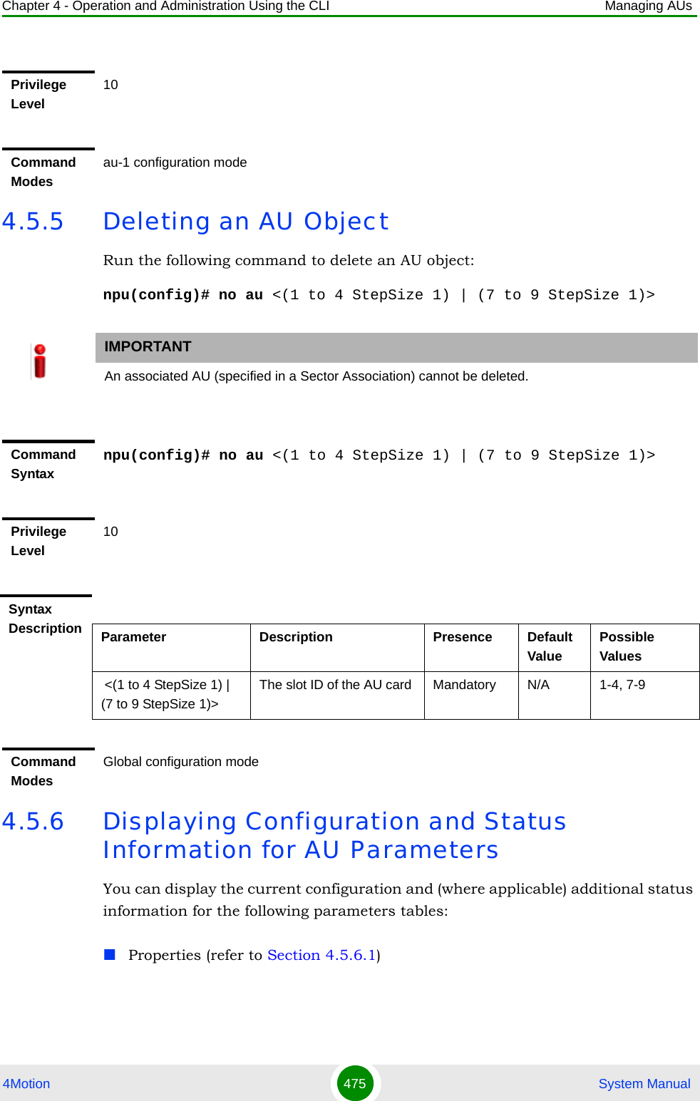
![Chapter 4 - Operation and Administration Using the CLI Managing AUs4Motion 476 System ManualControl (refer to Section 4.5.6.2)Connectivity (refer to Section 4.5.6.3)Reserved (refer to Section 4.5.6.4)4.5.6.1 Displaying Configuration and Status Information for AU PropertiesTo display configuration and status information for the properties of a specific or all AU objects, run the following command: npu# show properties au [<(1 to 4 StepSize 1) | (7 to 9 StepSize 1)>]Specify the au slot ID (1-4, 7-9) if you want to display configuration and status information for a particular AU. Do not specify a value for this parameter if you want to view configuration and status information for all existing AU objects.Command Syntaxnpu# show properties au [<(1 to 4 StepSize 1) | (7 to 9 StepSize 1)>]Privilege Level1Syntax Description Parameter Description Presence Default ValuePossible Values[<(1 to 4 StepSize 1) | (7 to 9 StepSize 1)>]The slot ID of the AU Specify a value for this parameter if you want to display the properties of a specific AU. Do not specify a value for this parameter if you want to display the properties of all AUs.Optional N/A 1-4, 7-9](https://usermanual.wiki/Alvarion-Technologies/BMAX-OR-25.Manual-2/User-Guide-1114030-Page-380.png)
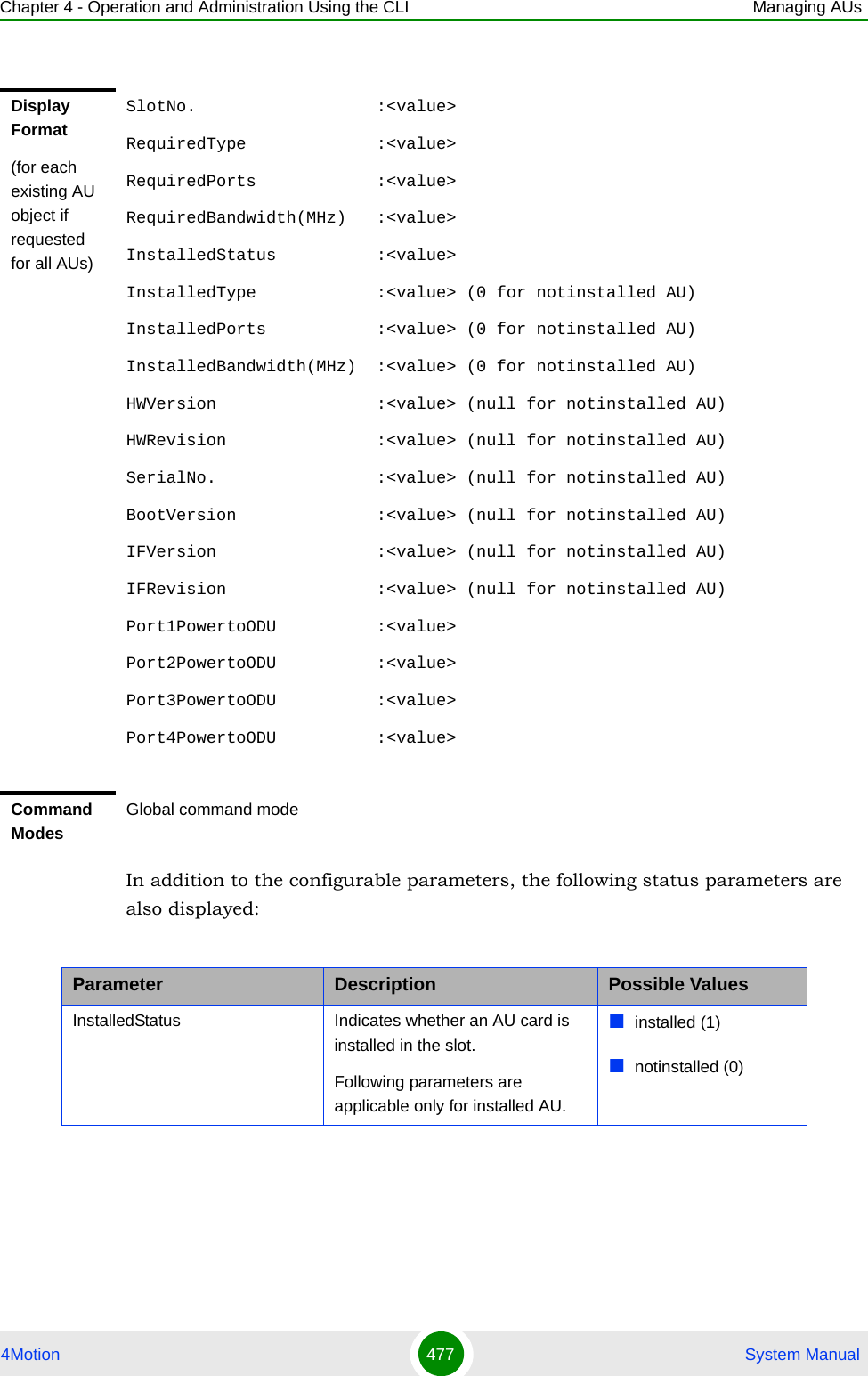
![Chapter 4 - Operation and Administration Using the CLI Managing AUs4Motion 478 System Manual4.5.6.2 Displaying Configuration for AU ControlTo display configuration for the Control parameter of a specific or all AU objects, run the following command: npu# show control au [<(1 to 4 StepSize 1) | (7 to 9 StepSize 1)>]Specify the au slot ID (1-4, 7-9) if you want to display configuration information for a particular AU. Do not specify a value for this parameter if you want to view configuration information for all existing AU objects.InstalledType The AU Type. threeDSP (1)twoDSP (2)other (3)auNotDetected (4)InstalledPorts The number of ODU ports. two (1)four (2)other (3)auNotDetected (4)InstalledBandwidth(MHz) The bandwidth supported by the AU.fourteen (1)twenty (2)other (3)auNotDetected (4)HWVersion AU HW Version number <number>HWRevision AU HW Revision number <number>SerialNo. AU Serial number <number>BootVersion AU Boot SW Version number <string>IFVersion AU IF Version number <number>IFRevision AU HW Revision number <number>Command Syntaxnpu# show control au [<(1 to 4 StepSize 1) | (7 to 9 StepSize 1)>]Privilege Level1Parameter Description Possible Values](https://usermanual.wiki/Alvarion-Technologies/BMAX-OR-25.Manual-2/User-Guide-1114030-Page-382.png)
![Chapter 4 - Operation and Administration Using the CLI Managing AUs4Motion 479 System Manual4.5.6.3 Displaying Configuration Information for AU Connectivity ParametersTo display configuration information for the connectivity parameters of a specific or all AU objects, run the following command: npu# show connectivity au [<(1 to 4 StepSize 1) | (7 to 9 StepSize 1)>]Specify the au slot ID (1-4, 7-9) if you want to display configuration for a particular AU. Do not specify a value for this parameter if you want to view configuration for all existing AU objects.The displayed information includes also configured values for relevant parameters that are configured for the internal management interface of the NPU.Syntax Description Parameter Description Presence Default ValuePossible Values[<(1 to 4 StepSize 1) | (7 to 9 StepSize 1)>]The slot ID of the AU Specify a value for this parameter if you want to display the control parameter of a specific AU. Do not specify a value for this parameter if you want to display the control parameters of all AUs.Optional N/A 1-4, 7-9Display Format(for each existing AU object if requested for all AUs)SlotNo. :<value>AUPowerControl :<value>Command ModesGlobal command modeCommand Syntaxnpu# show connectivity au [<(1 to 4 StepSize 1) | (7 to 9 StepSize 1)>]](https://usermanual.wiki/Alvarion-Technologies/BMAX-OR-25.Manual-2/User-Guide-1114030-Page-383.png)
![Chapter 4 - Operation and Administration Using the CLI Managing AUs4Motion 480 System ManualIn addition to the configurable parameters, the following status parameters are also displayed:Privilege Level1Syntax Description Parameter Description Presence Default ValuePossible Values[<(1 to 4 StepSize 1) | (7 to 9 StepSize 1)>]The slot ID of the AU Specify a value for this parameter if you want to display the connectivity parameters of a specific AU. Do not specify a value for this parameter if you want to display the connectivity parameters of all AUs.Optional N/A 1-4, 7-9Display Format(for each existing AU object if requested for all AUs)SlotNo. :<value>EncapsulationMode :vlanAwareBridging(0)MaxFrameSize(Bytes) :<value>InternalManagementVLANID :<value>BearerVLANID :<value>InternalManagementIPAddress :<value>InternalManagementIPSubnetMask :<value>Command ModesGlobal command modeParameter Description Possible ValuesEncapsulationMode The Ethernet encapsulation mode of the card’s Ethernet port (hard coded in production).vlanAwareBridging(0)InternalManagementVLANID The VLAN ID Management of the shelf.(hard coded in production)0-4092](https://usermanual.wiki/Alvarion-Technologies/BMAX-OR-25.Manual-2/User-Guide-1114030-Page-384.png)
![Chapter 4 - Operation and Administration Using the CLI Managing AUs4Motion 481 System Manual4.5.6.4 Displaying Configuration Information for AU Reserved ParametersTo display configuration information for the reserved parameters of a specific or all AU objects, run the following command: npu# show au-reserved au [<(1 to 4 StepSize 1) | (7 to 9 StepSize 1)>]Specify the au slot ID (1-4, 7-9) if you want to display configuration for a particular AU. Do not specify a value for this parameter if you want to view configuration for all existing AU objects.InternalManagementIPAddress IP Address of the internainterface of the AU. Acquired via DHCP.IP addressInternalManagementIPSubnetMask Subnet Mask of the internainterface of the AU. Acquired via DHCP.Subnet maskCommand Syntaxnpu# show au-reserved au [<(1 to 4 StepSize 1) | (7 to 9 StepSize 1)>]Privilege Level1Syntax Description Parameter Description Presence Default ValuePossible Values[<(1 to 4 StepSize 1) | (7 to 9 StepSize 1)>]The slot ID of the AU Specify a value for this parameter if you want to display the reserved parameters of a specific AU. Do not specify a value for this parameter if you want to display the reserved parameters of all AUs.Optional N/A 1-4, 7-9](https://usermanual.wiki/Alvarion-Technologies/BMAX-OR-25.Manual-2/User-Guide-1114030-Page-385.png)