Alvarion Technologies BMAX-OR-25 BreezeMax 4Motion Broadband Wireless System User Manual 4Motion System Manual
Alvarion Technologies Ltd. BreezeMax 4Motion Broadband Wireless System 4Motion System Manual
Contents
- 1. Manual 1
- 2. Manual 2
- 3. Manual 3
- 4. Manual 4
- 5. Manual
Manual 4
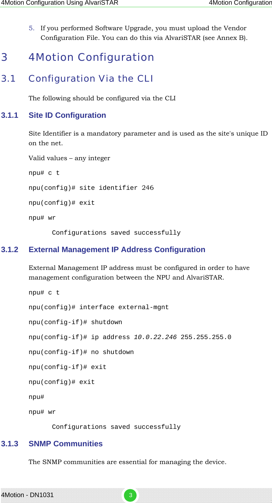
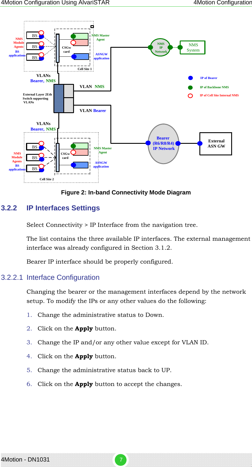
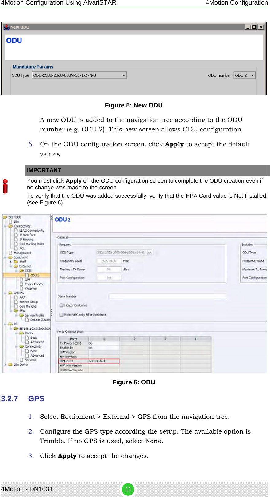
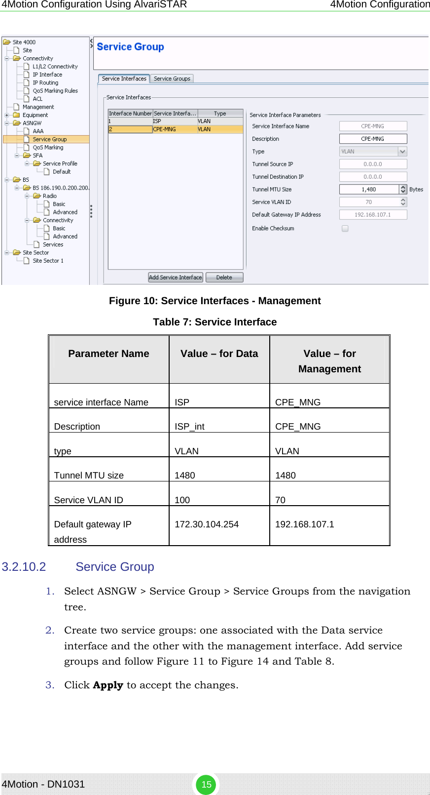
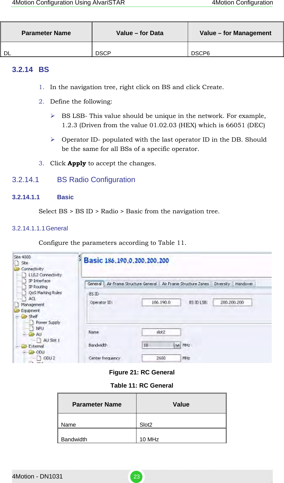
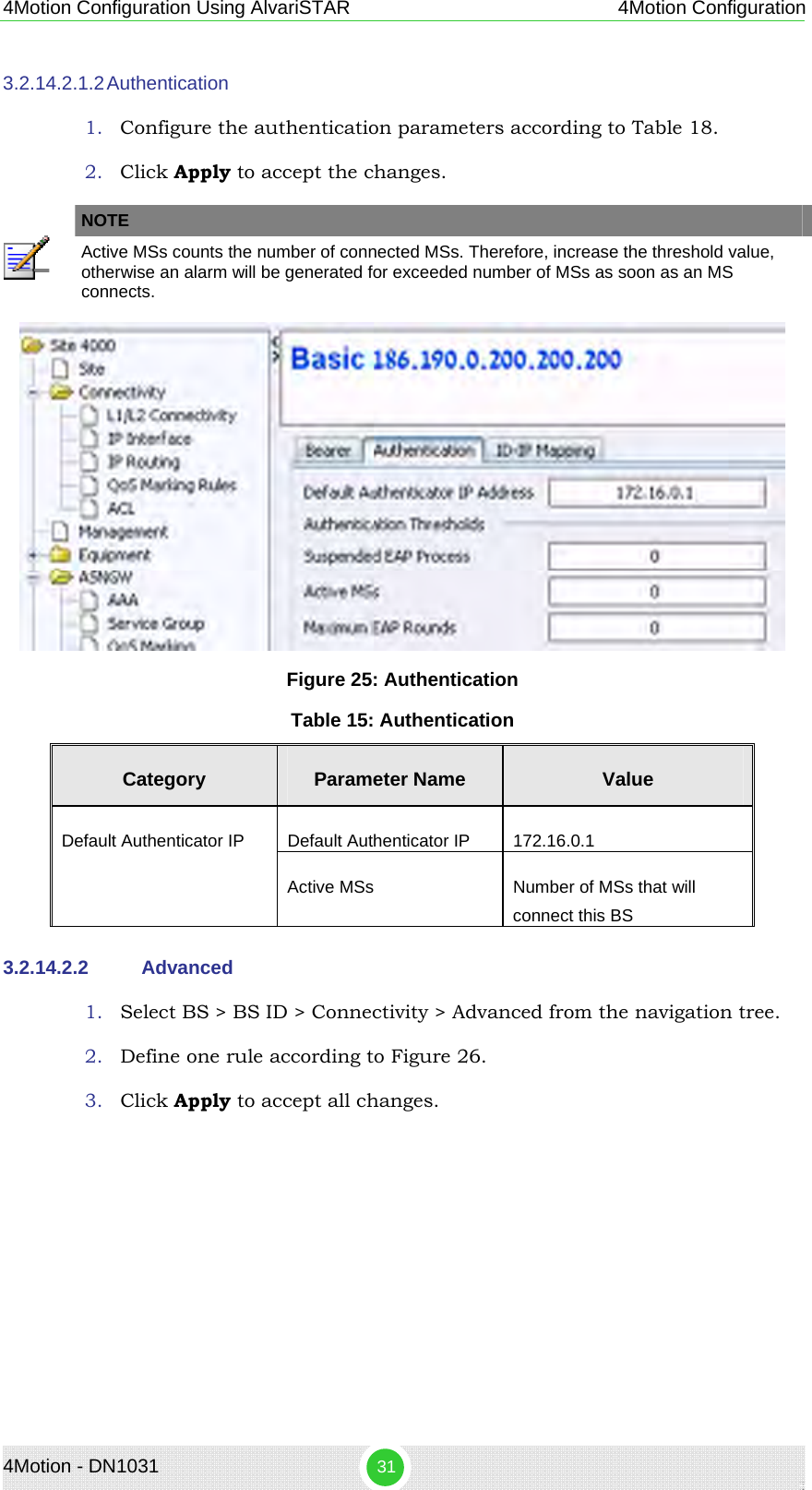
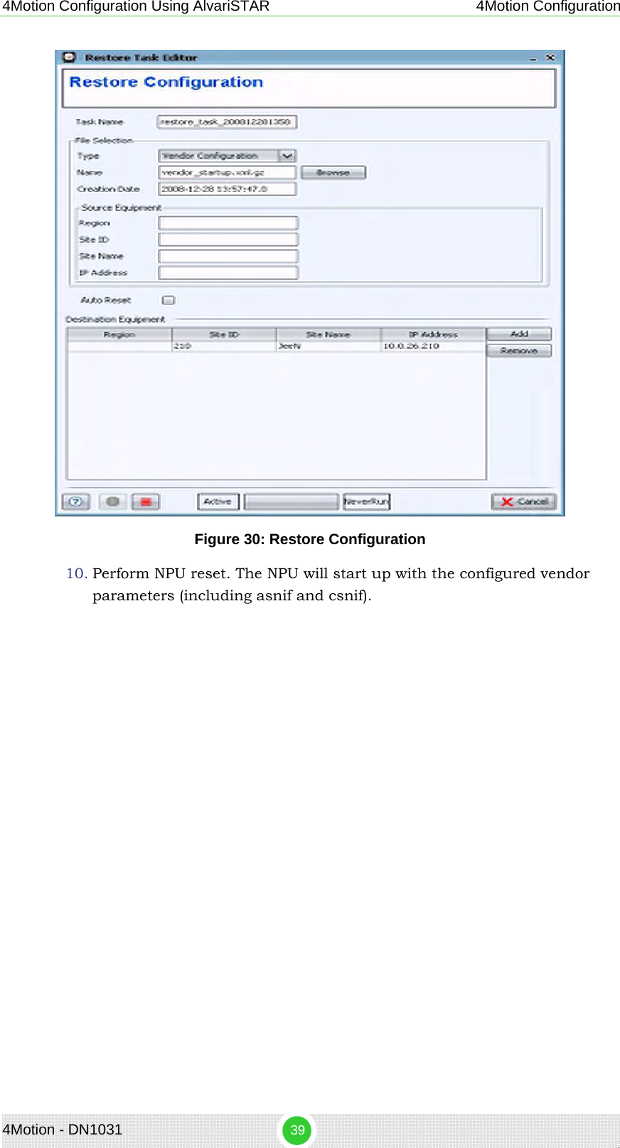
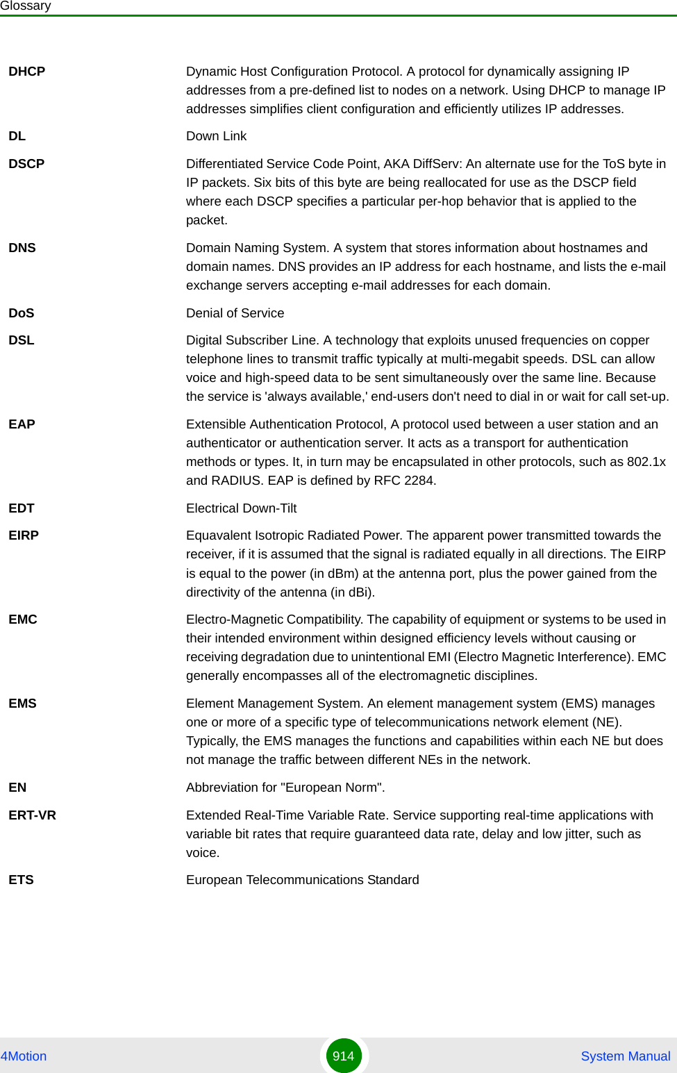
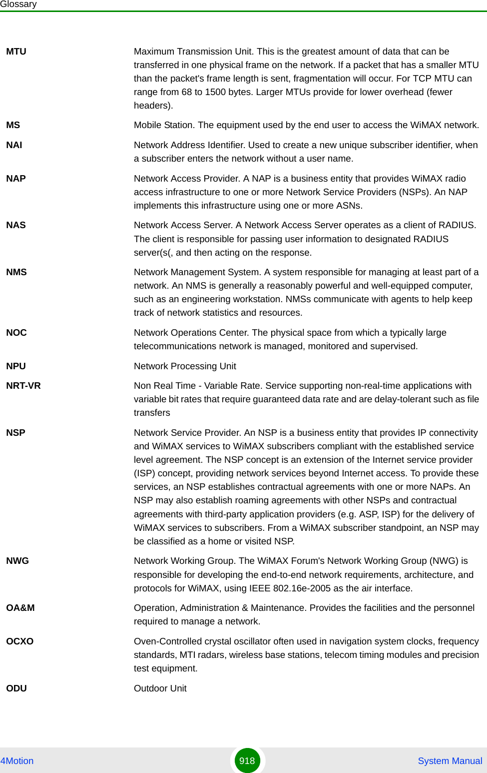
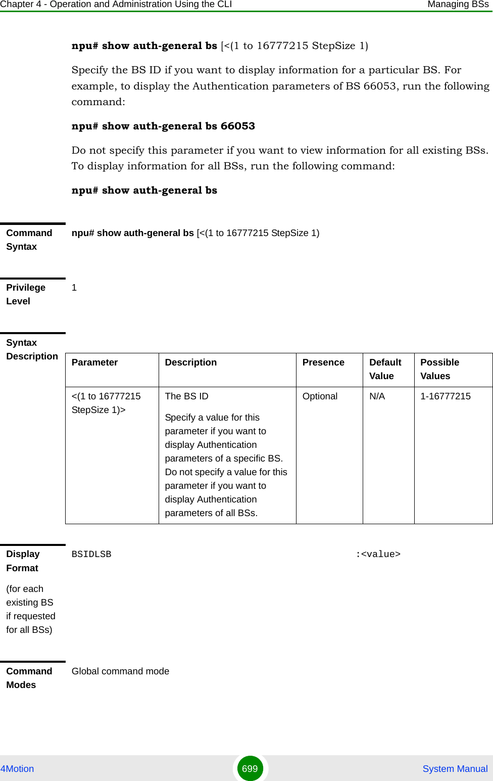
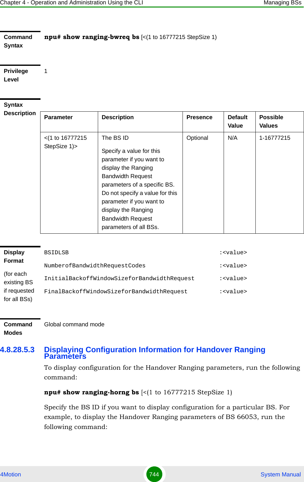
![Chapter 4 - Operation and Administration Using the CLI Managing BSs4Motion 682 System Manual4.8.19.5.12 Displaying Configuration Information for All Airframe ParametersTo display configuration for all Airframe parameters, run the following command:npu# show airframe-all bs [<(1 to 16777215 StepSize 1)>]Specify the BS ID if you want to display configuration for a particular BS. For example, to display all Airframe parameters of BS 66503, run the following command:npu# show airframe-all bs 66053 Do not specify the BS ID if you want to view configuration information for all existing BSs. To display information for all BSs, run the following command:npu# show airframe-all bsSyntax Description Parameter Description Presence Default ValuePossible Values<(1 to 16777215 StepSize 1)>The BS ID Specify a value for this parameter if you want to display the Airframe Dynamic Permutation parameters of a specific BS. Do not specify a value for this parameter if you want to display the Airframe Dynamic Permutation parameters of all BSs.Optional N/A 1-16777215Display Format(for each existing Neighbour BS in each of the existing BSs if requested for all)BSIDLSB :<value>DownlinkPermutationBase :<value>UplinkPermutationBase :<value>Command ModesGlobal command mode](https://usermanual.wiki/Alvarion-Technologies/BMAX-OR-25.Manual-4/User-Guide-1114032-Page-1.png)
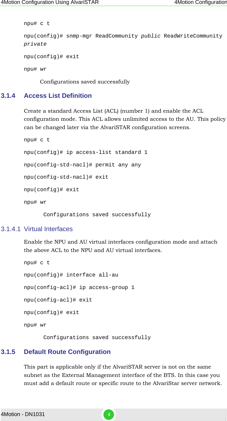
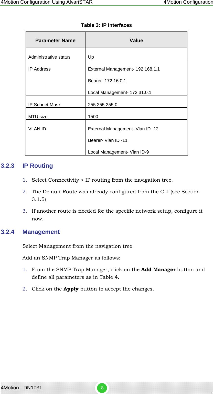
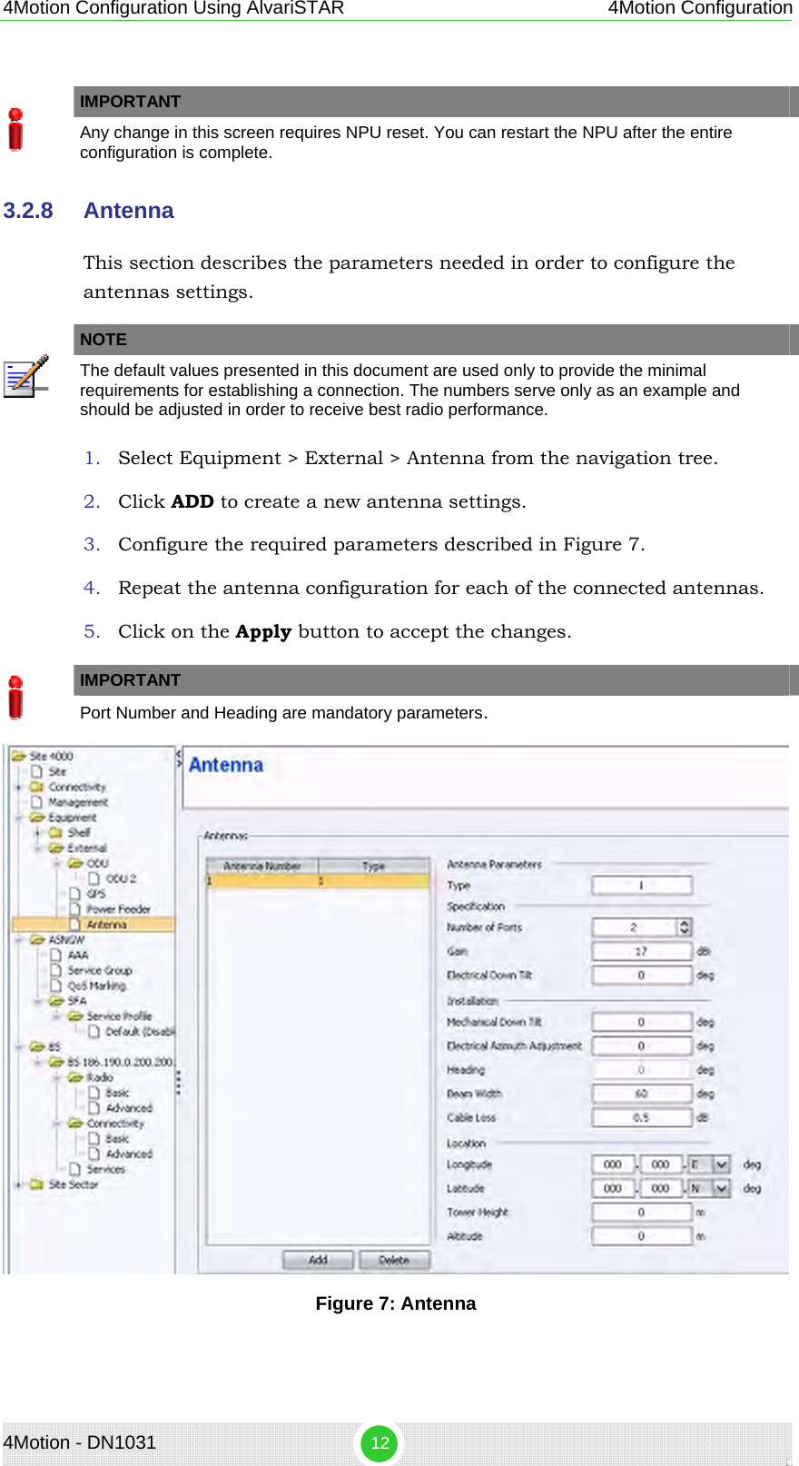
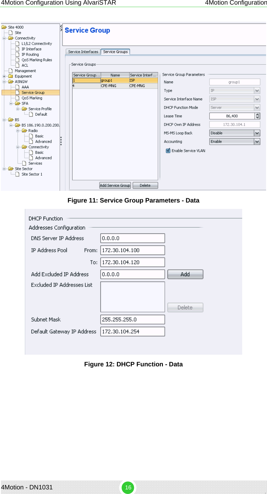
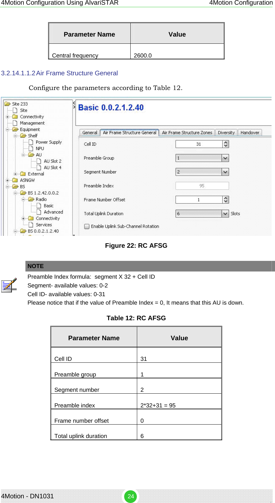
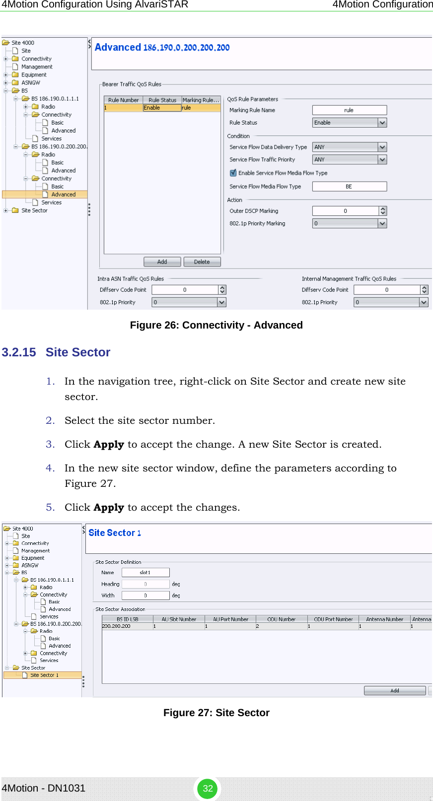
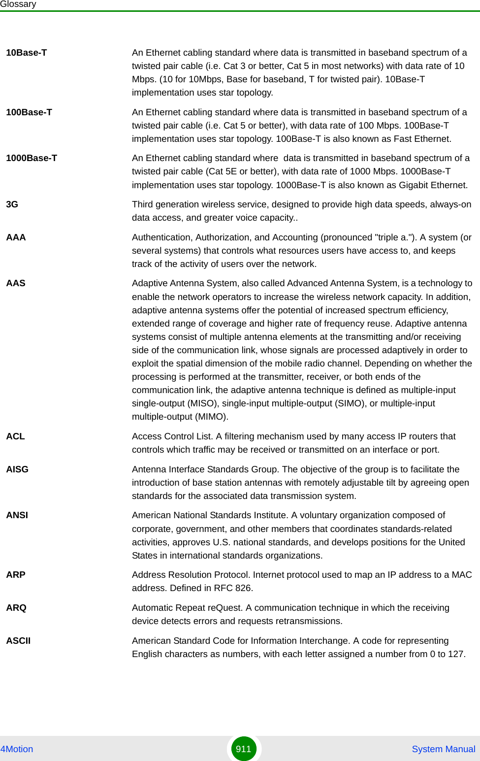
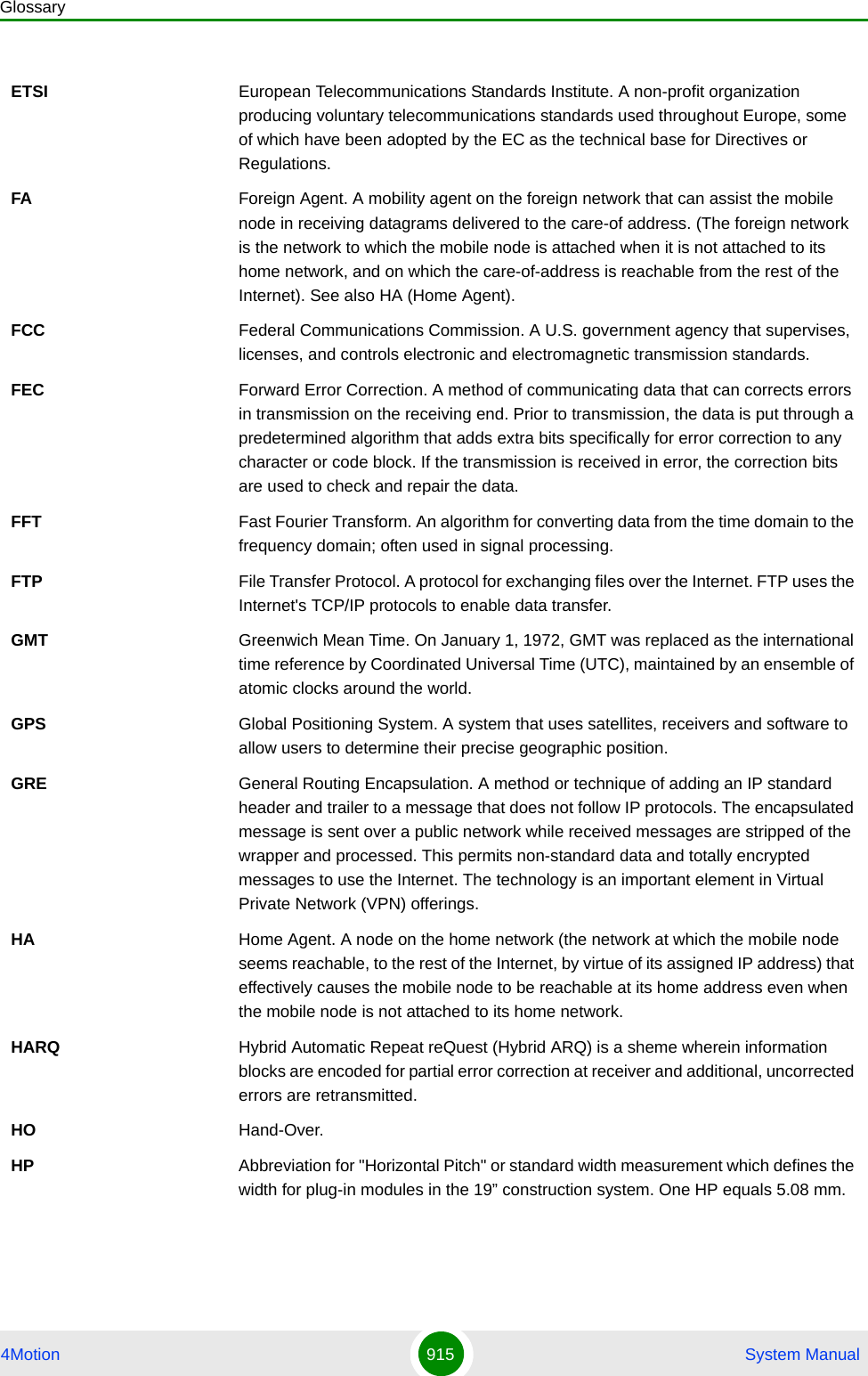
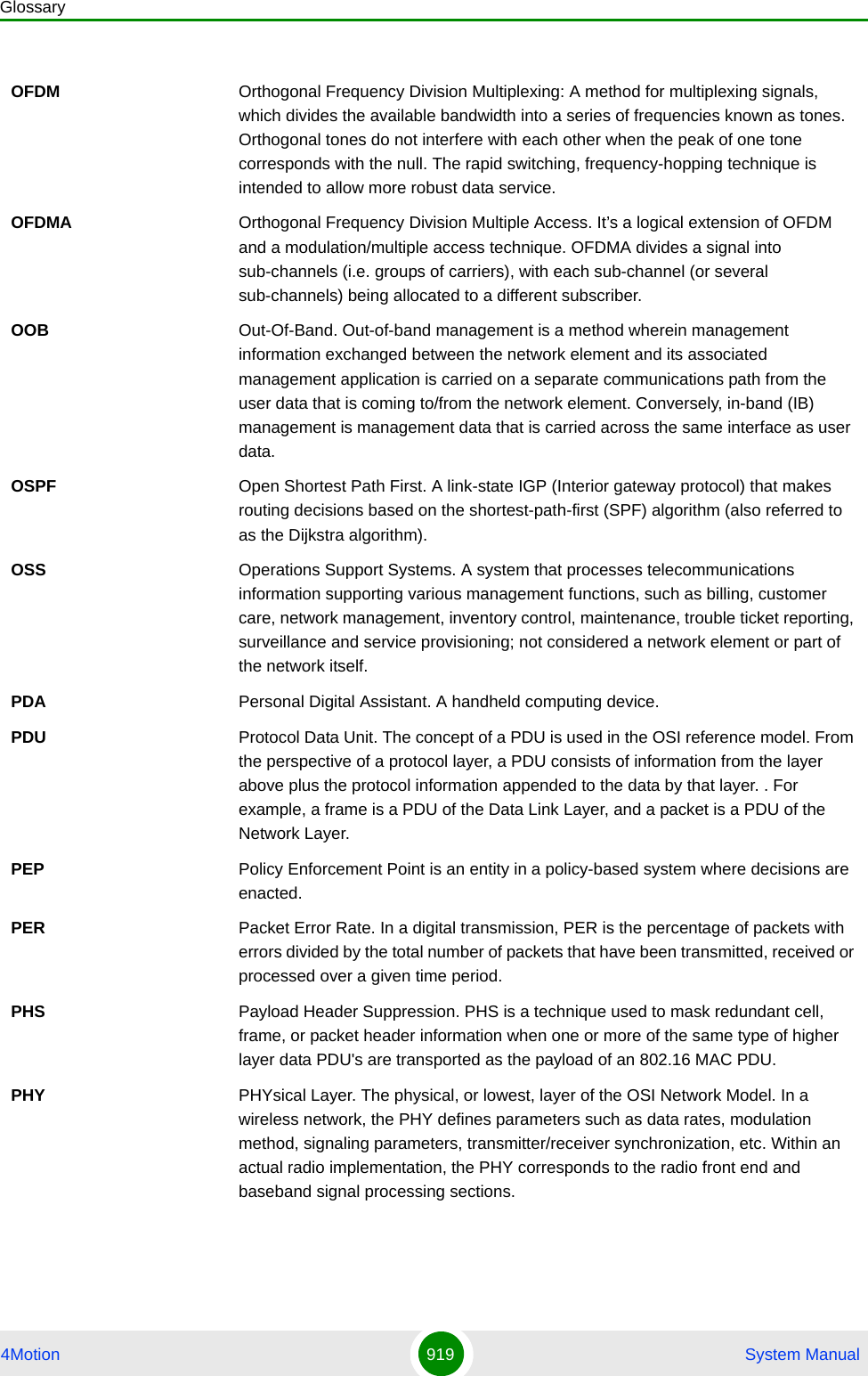
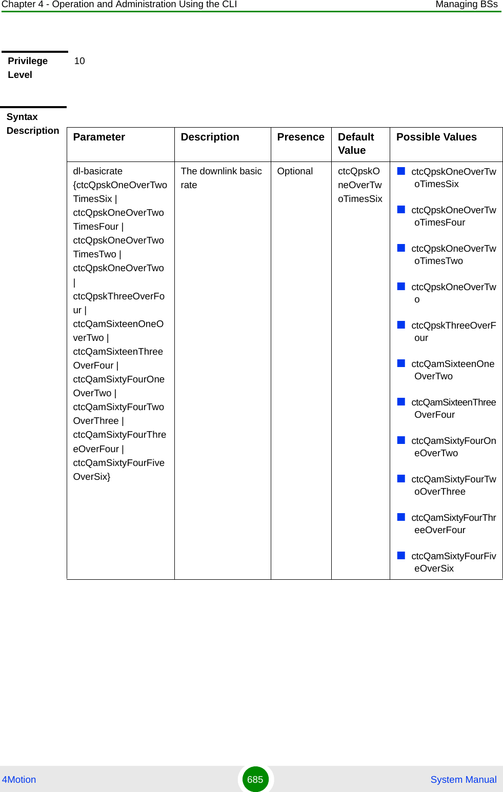
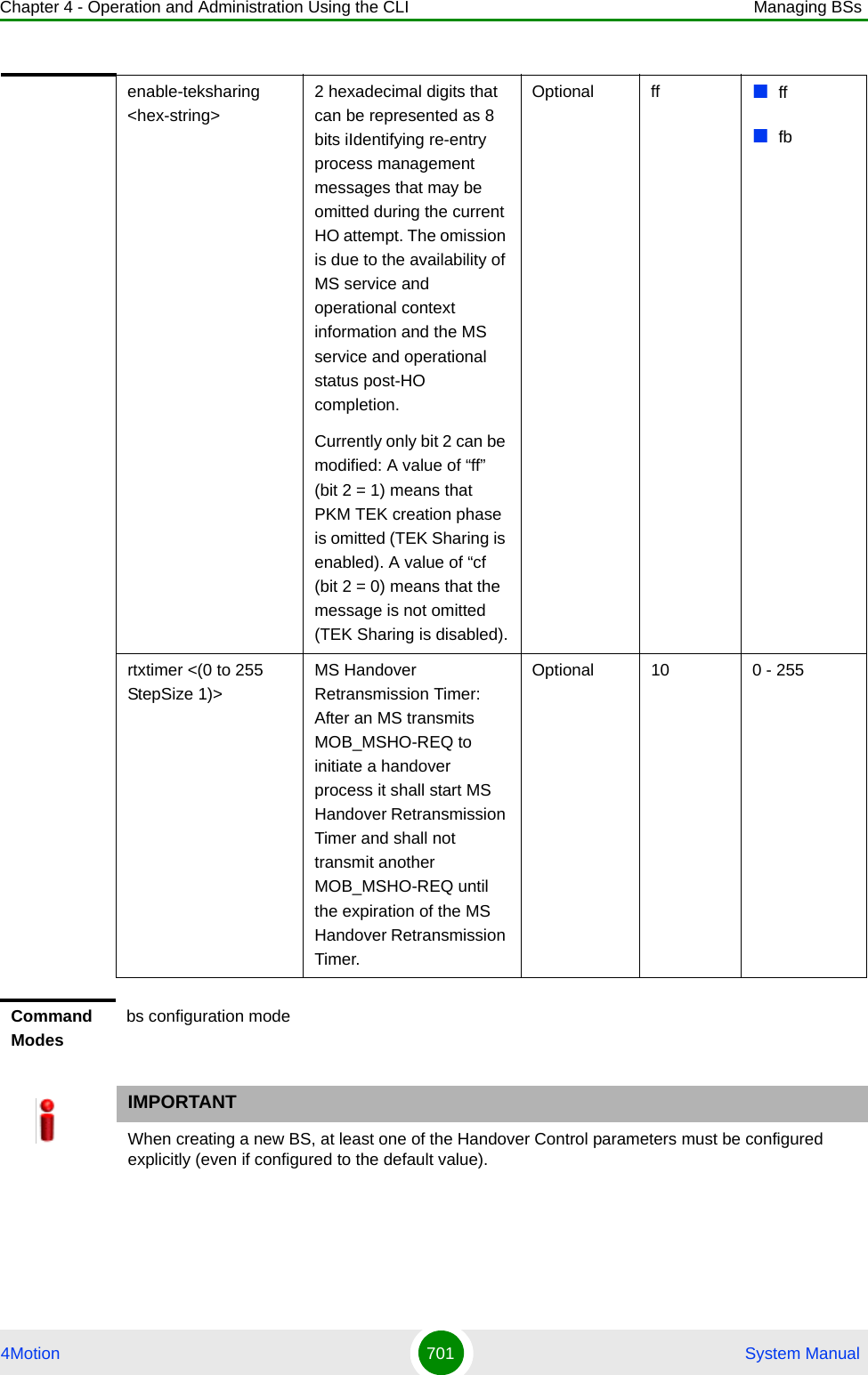
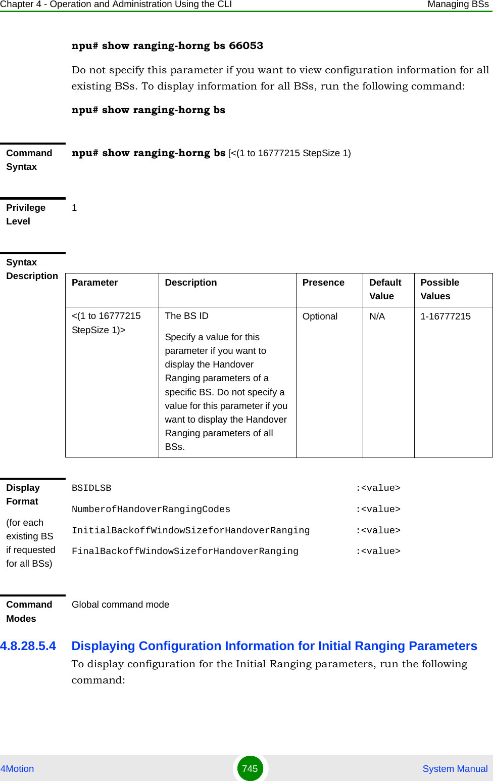
![Chapter 4 - Operation and Administration Using the CLI Managing BSs4Motion 683 System Manual4.8.20 Managing Rate Adaptation ParametersAfter enabling the BS configuration mode, you can execute the following tasks:Configure one or more of the Rate Adaptation parameters (refer to Section 4.8.20.1).Restore the default values of some or all of the Rate Adaptation parameters (refer to Section 4.8.20.2).You can display configuration information for the Rate Adaptation parameters of a selected or all existing BSs (refer to Section 4.8.20.3).4.8.20.1 Configuring Rate Adaptation ParametersFrom the BS configuration mode, run the following command:Command Syntaxnpu# show airframe-all bs [<(1 to 16777215 StepSize 1)> ]Privilege Level10Syntax Description Parameter Description Presence Default ValuePossible Values<(1 to 16777215 StepSize 1)>The BS ID Specify a value for this parameter if you want to display all Airframe parameters of a specific BS. Do not specify a value for this parameter if you want to display all Airframe parameters of all BSs.Optional N/A 1-16777215Command ModesGlobal command modeTo configure the Rate Adaptation parameters:](https://usermanual.wiki/Alvarion-Technologies/BMAX-OR-25.Manual-4/User-Guide-1114032-Page-2.png)
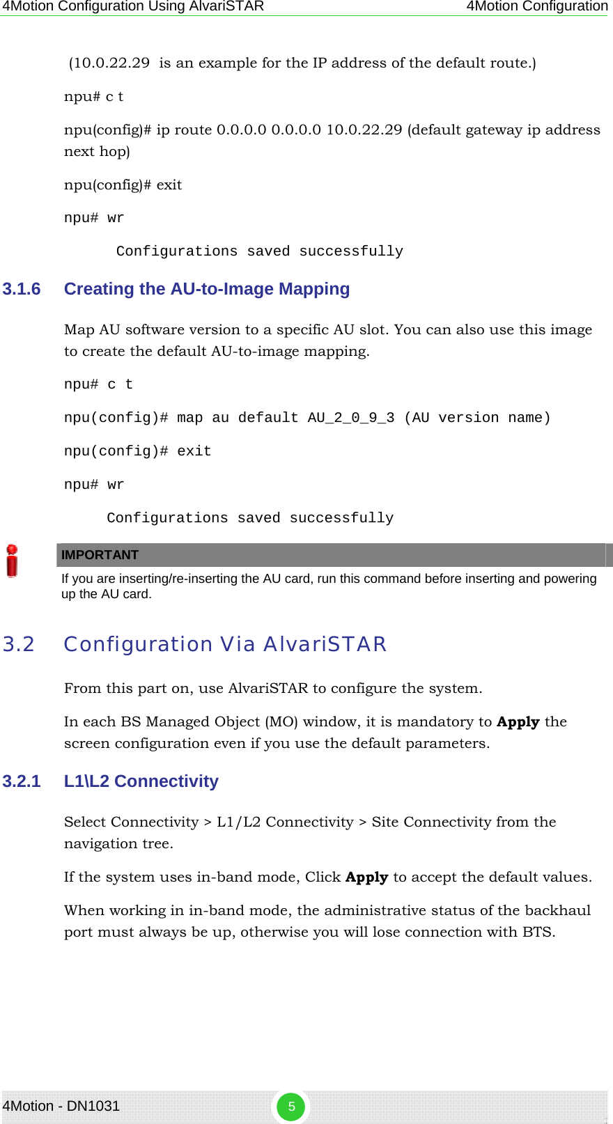
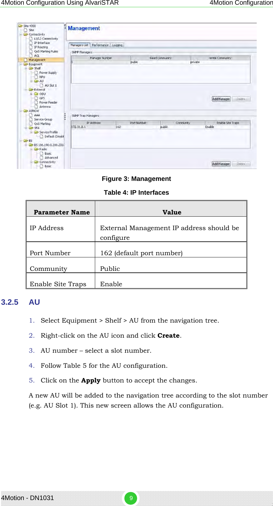
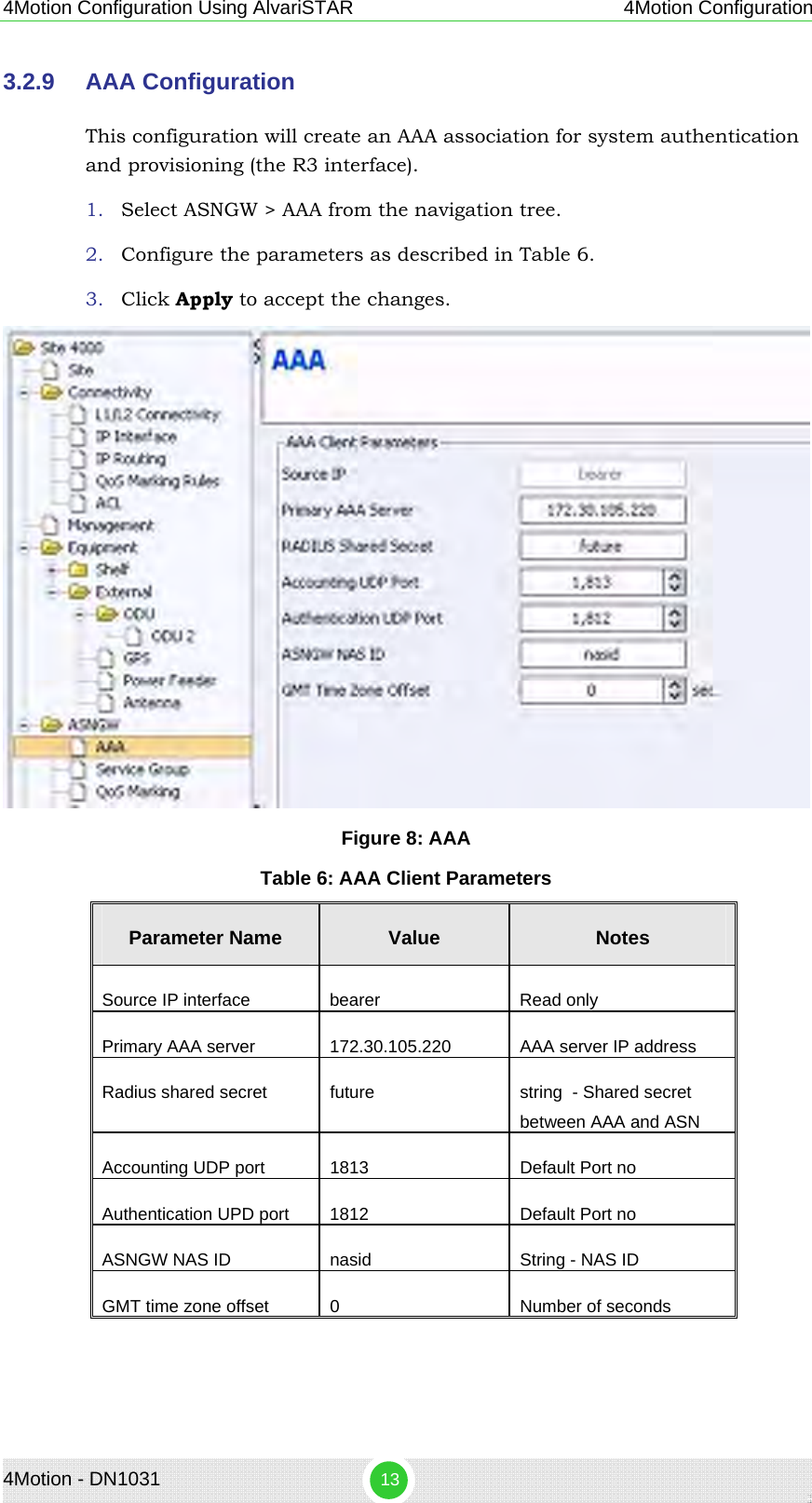
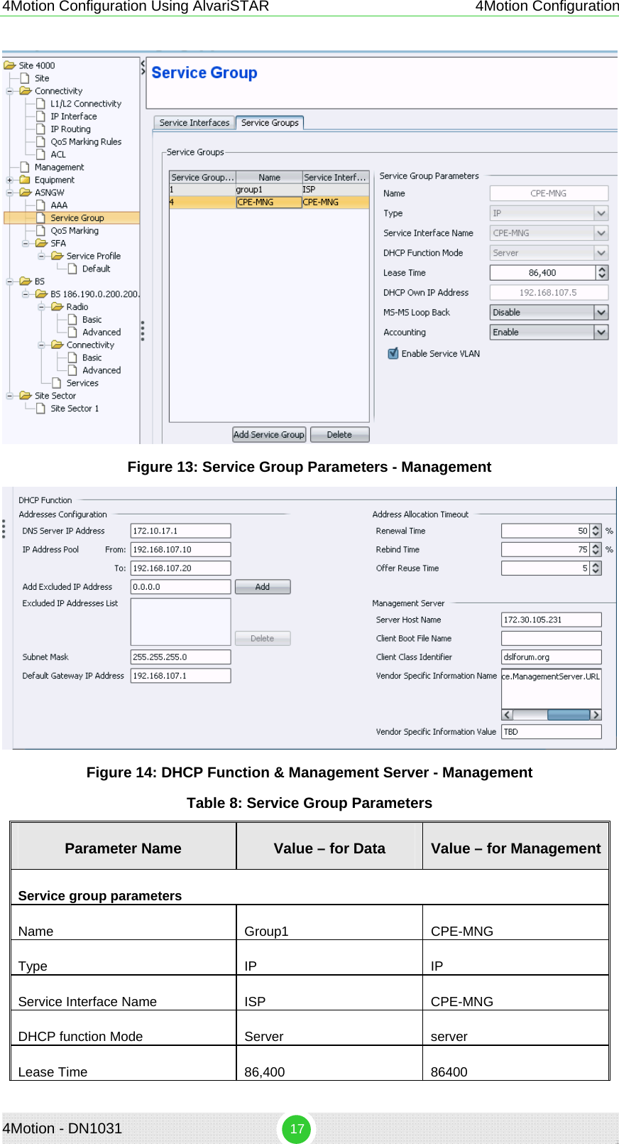
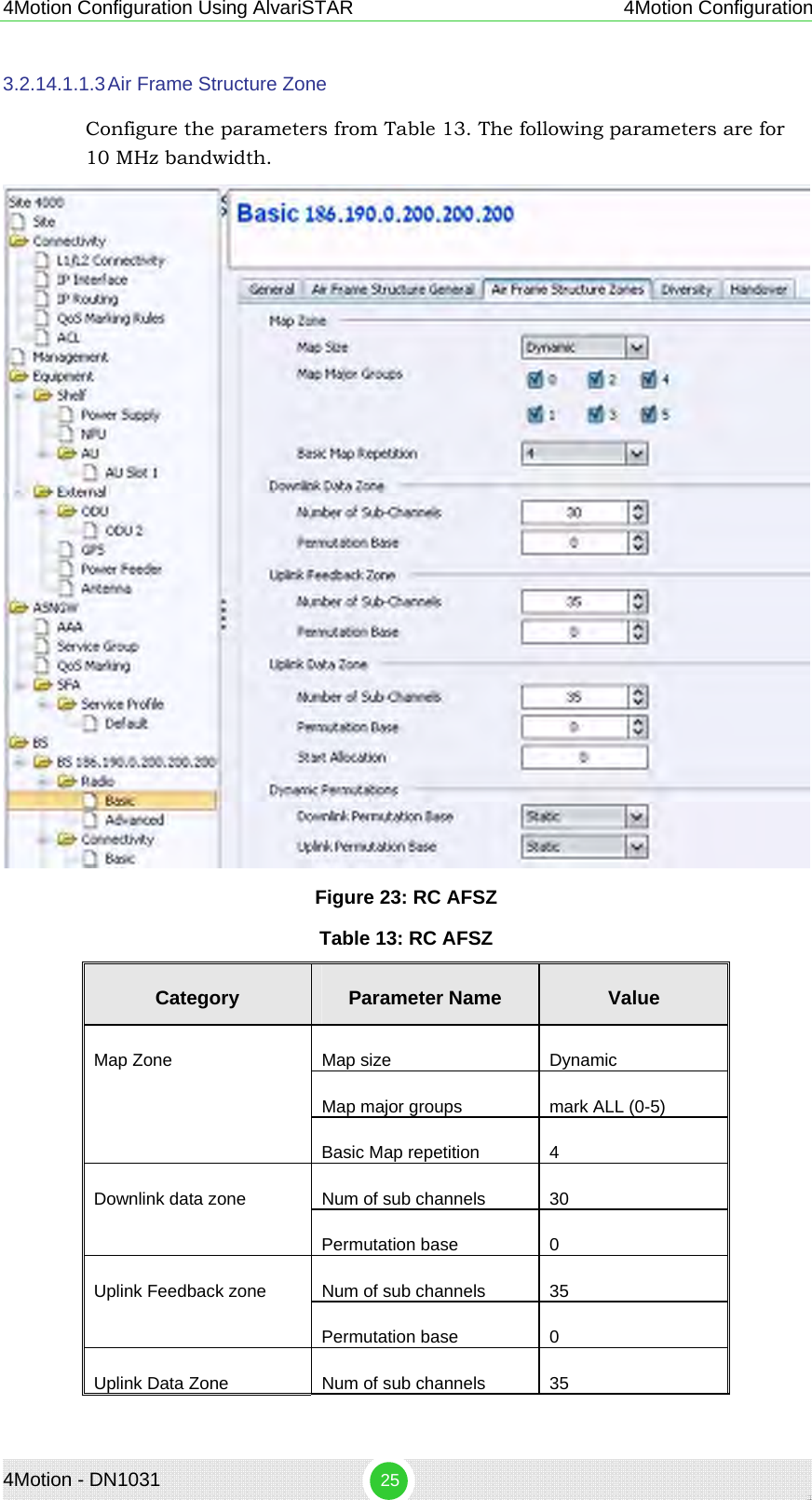
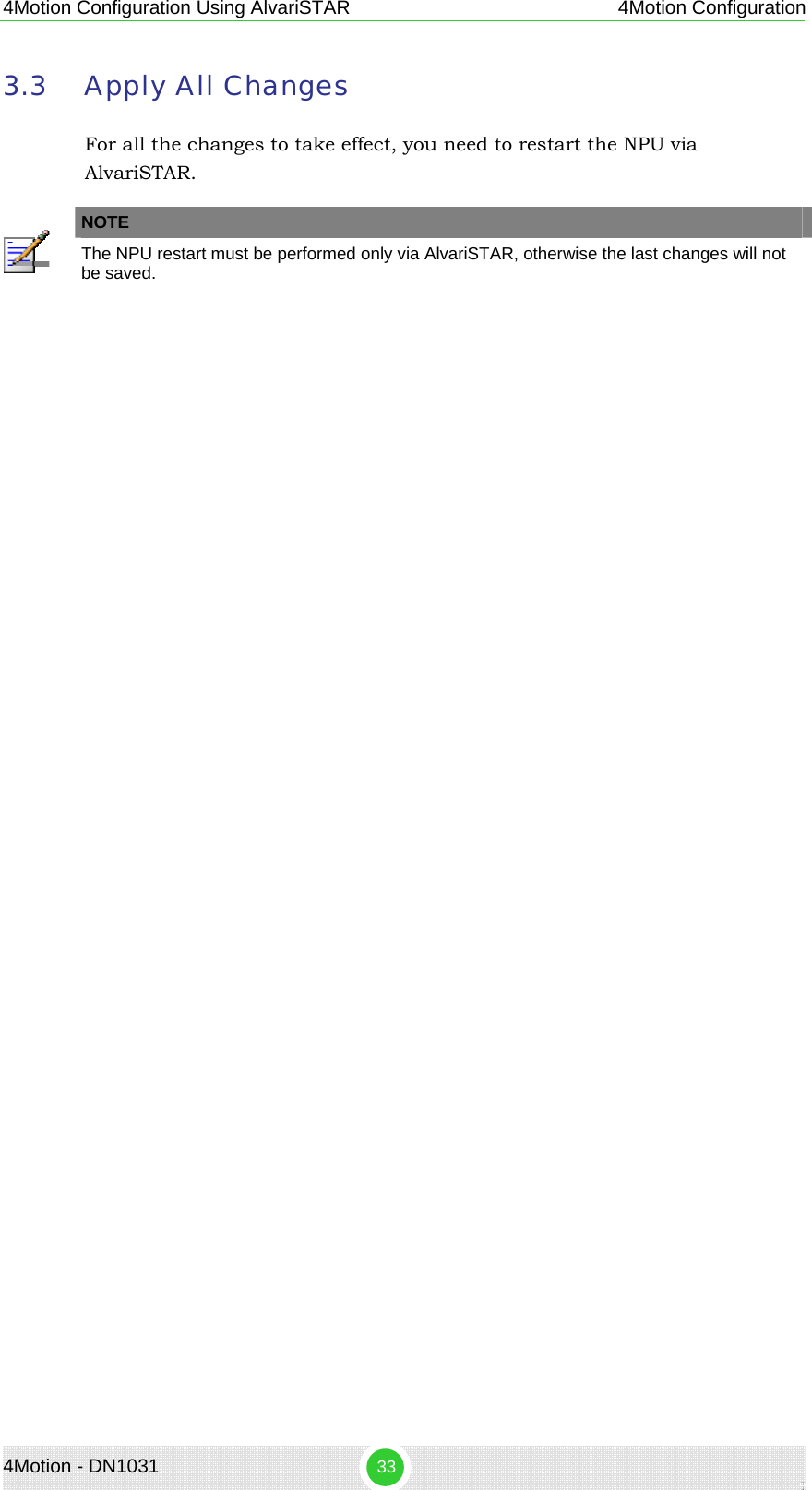
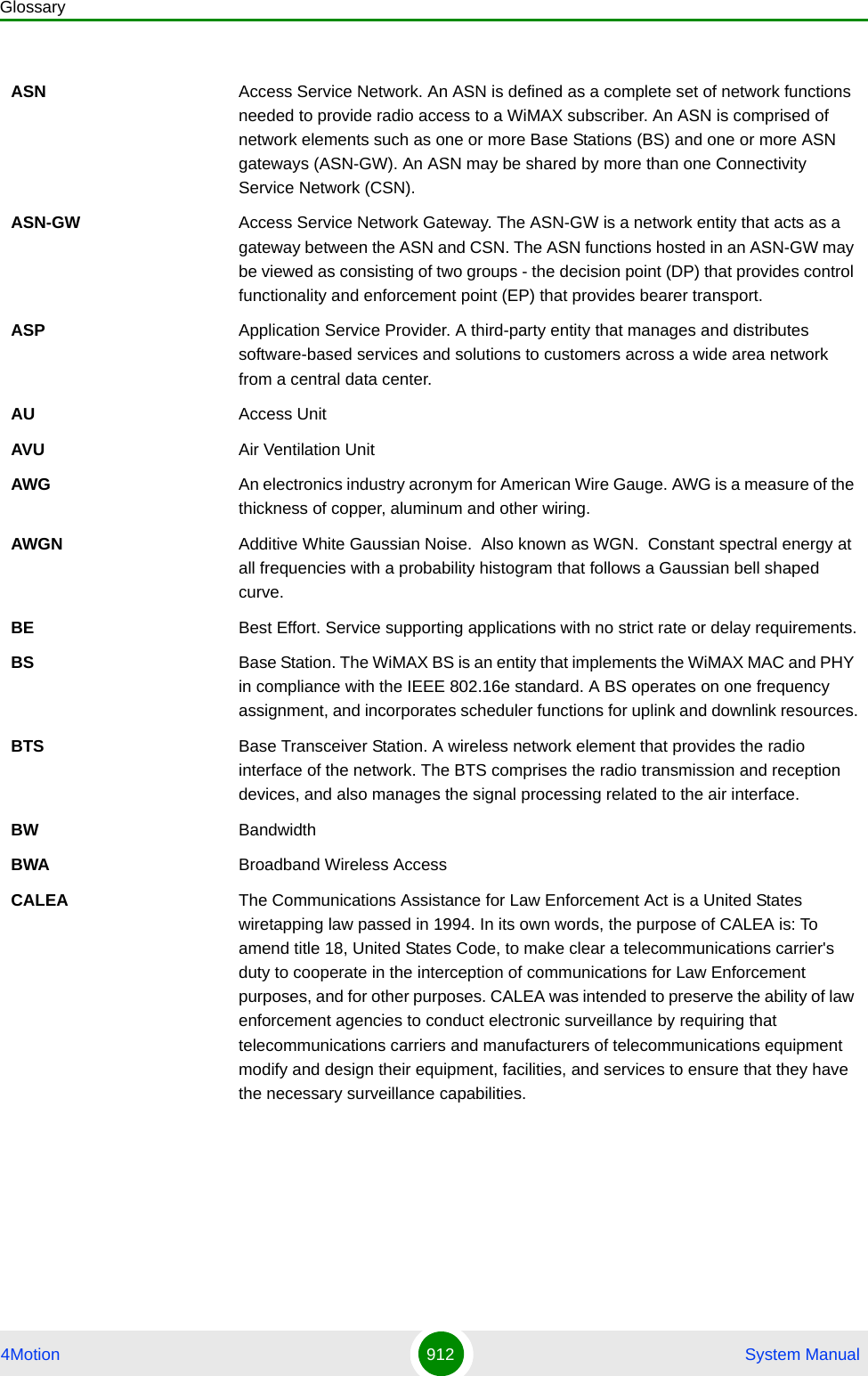
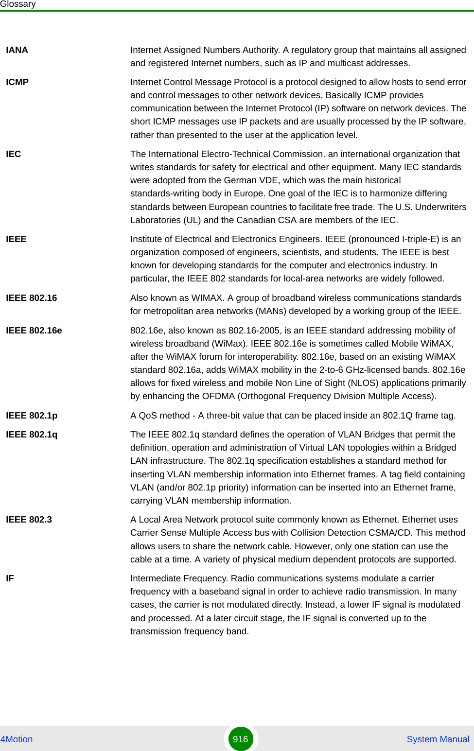
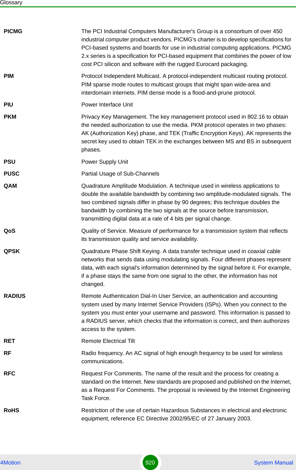
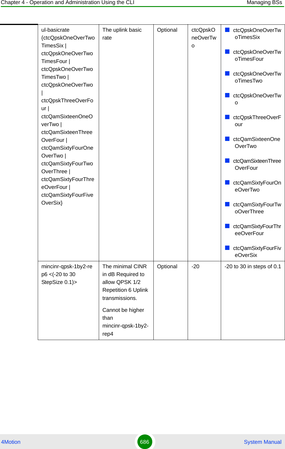
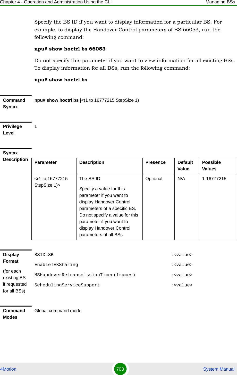
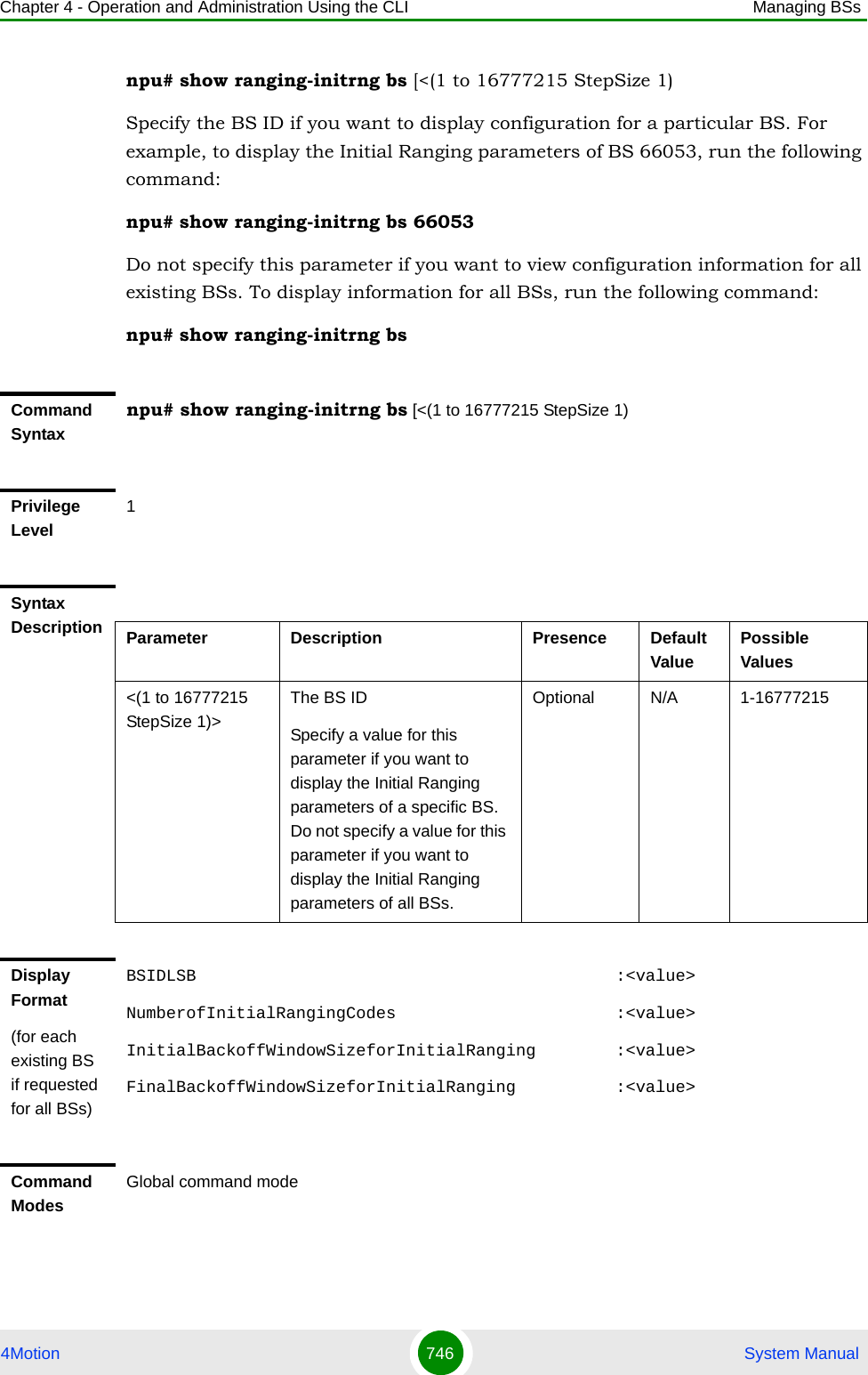
![Chapter 4 - Operation and Administration Using the CLI Managing BSs4Motion 684 System Manualnpu(config-bs-66053)# rateadapt-general [dl-basicrate {ctcQpskOneOverTwoTimesSix | ctcQpskOneOverTwoTimesFour | ctcQpskOneOverTwoTimesTwo | ctcQpskOneOverTwo | ctcQpskThreeOverFour | ctcQamSixteenOneOverTwo | ctcQamSixteenThreeOverFour | ctcQamSixtyFourOneOverTwo | ctcQamSixtyFourTwoOverThree | ctcQamSixtyFourThreeOverFour | ctcQamSixtyFourFiveOverSix}] [ul-basicrate {ctcQpskOneOverTwoTimesSix | ctcQpskOneOverTwoTimesFour | ctcQpskOneOverTwoTimesTwo | ctcQpskOneOverTwo | ctcQpskThreeOverFour |ctcQamSixteenOneOverTwo | ctcQamSixteenThreeOverFour | ctcQamSixtyFourOneOverTwo | ctcQamSixtyFourTwoOverThree | ctcQamSixtyFourThreeOverFour | ctcQamSixtyFourFiveOverSix}] [mincinr-qpsk-1by2-rep6 <(-20 to 30 StepSize 0.1)>] [mincinr-qpsk-1by2-rep4 <(-20 to 30 StepSize 0.1)>] [mincinr-qpsk-1by2-rep2 <(-20 to 30 StepSize 0.1)>] [mincinr-qpsk-1by2 <(-20 to 30 StepSize 1)>] [mincinr-qpsk-3by4 <(-20 to 30 StepSize 1)>] [mincinr-qam16-1by2 <(-20 to 30 StepSize 0.1)>] [mincinr-qam16-3by4 <(-20 to 30 StepSize 0.1)>] [mincinr-qam64-1by2 <(-20 to 30 StepSize 0.1)>] [mincinr-qam64-2by3 <(-20 to 30 StepSize 0.1)>] [mincinr-qam64-3by4 <(-20 to 30 StepSize 0.1)>] [mincinr-qam64-5by6 <(-20 to 30 StepSize 0.1)>]Command Syntaxnpu(config-bs-66053)# [dl-basicrate {ctcQpskOneOverTwoTimesSix | ctcQpskOneOverTwoTimesFour | ctcQpskOneOverTwoTimesTwo | ctcQpskOneOverTwo | ctcQpskThreeOverFour | ctcQamSixteenOneOverTwo | ctcQamSixteenThreeOverFour | ctcQamSixtyFourOneOverTwo | ctcQamSixtyFourTwoOverThree | ctcQamSixtyFourThreeOverFour | ctcQamSixtyFourFiveOverSix} ] [ul-basicrate {ctcQpskOneOverTwoTimesSix | ctcQpskOneOverTwoTimesFour | ctcQpskOneOverTwoTimesTwo | ctcQpskOneOverTwo | ctcQpskThreeOverFour |ctcQamSixteenOneOverTwo | ctcQamSixteenThreeOverFour | ctcQamSixtyFourOneOverTwo | ctcQamSixtyFourTwoOverThree | ctcQamSixtyFourThreeOverFour | ctcQamSixtyFourFiveOverSix} ] [mincinr-qpsk-1by2-rep6 <(-20 to 30 StepSize 0.1)> ] [mincinr-qpsk-1by2-rep4 <(-20 to 30 StepSize 0.1)> ] [mincinr-qpsk-1by2-rep2 <(-20 to 30 StepSize 0.1)> ] [mincinr-qpsk-1by2 <(-20 to 30 StepSize 1)> ] [mincinr-qpsk-3by4 <(-20 to 30 StepSize 1)> ] [mincinr-qam16-1by2 <(-20 to 30 StepSize 0.1)> ] [mincinr-qam16-3by4 <(-20 to 30 StepSize 0.1)> ] [mincinr-qam64-1by2 <(-20 to 30 StepSize 0.1)> ] [mincinr-qam64-2by3 <(-20 to 30 StepSize 0.1)> ] [mincinr-qam64-3by4 <(-20 to 30 StepSize 0.1)> ] [mincinr-qam64-5by6 <(-20 to 30 StepSize 0.1)> ]](https://usermanual.wiki/Alvarion-Technologies/BMAX-OR-25.Manual-4/User-Guide-1114032-Page-3.png)
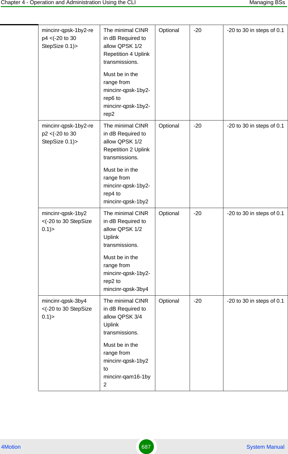
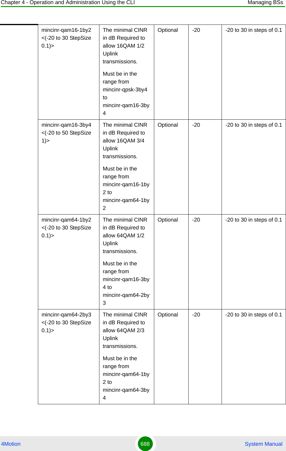
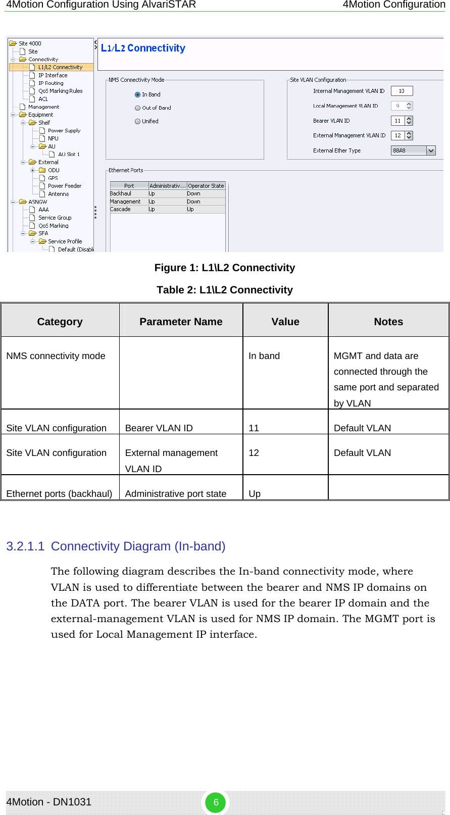
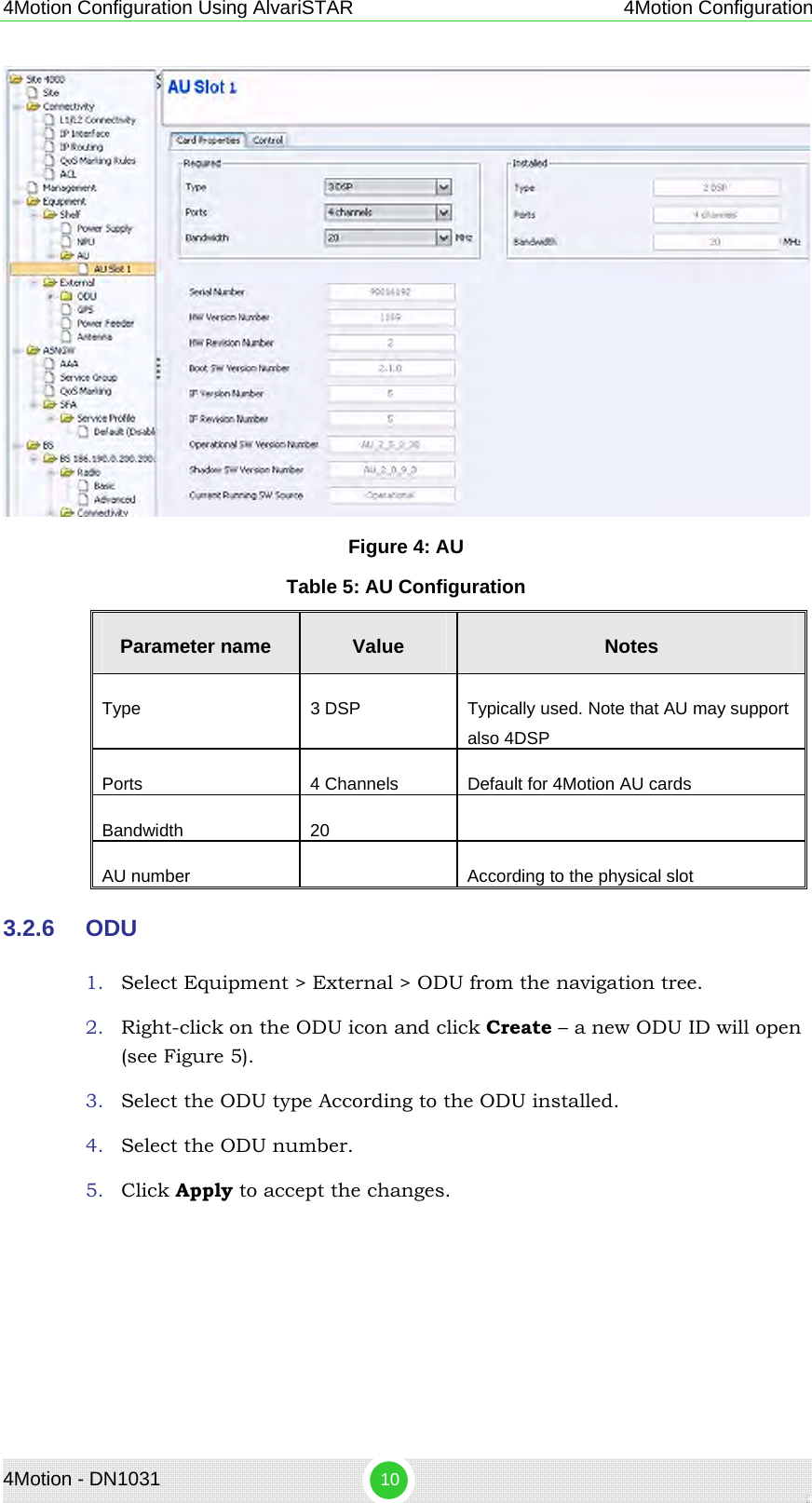
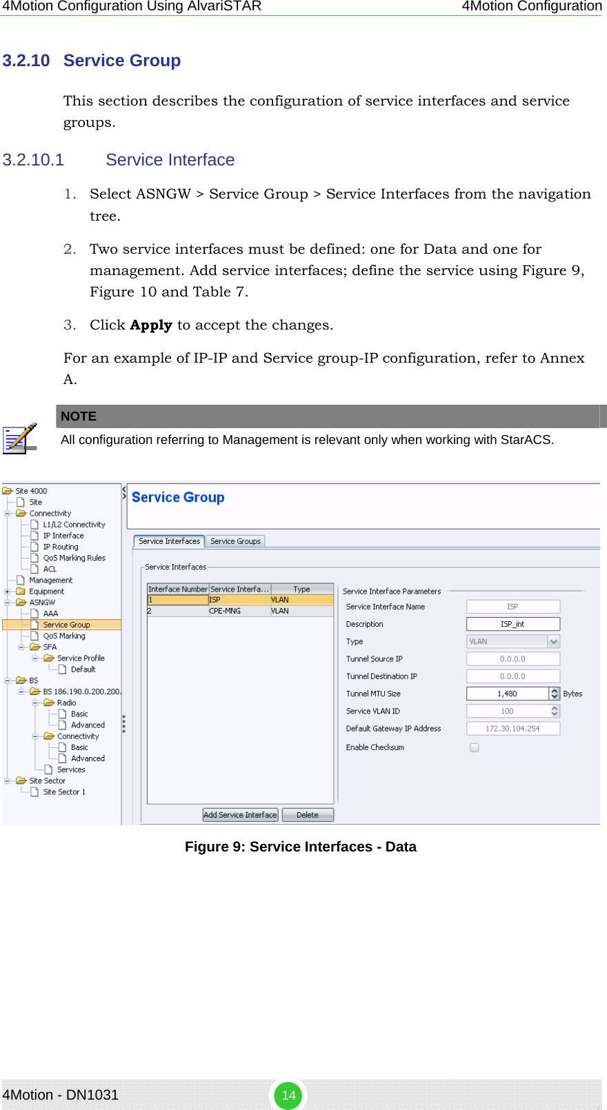
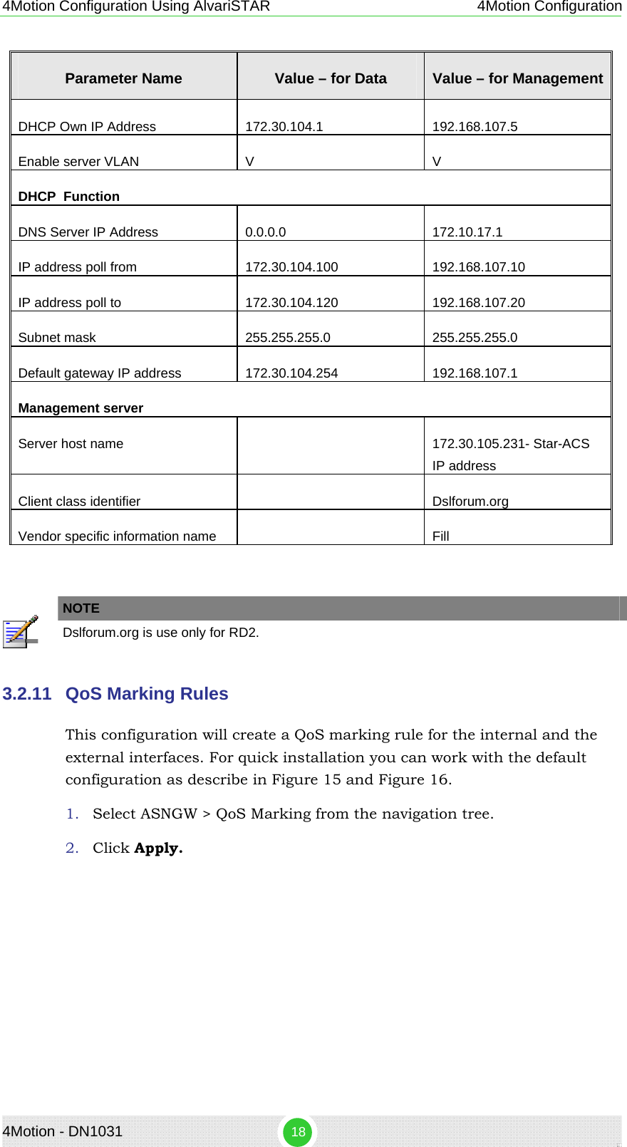
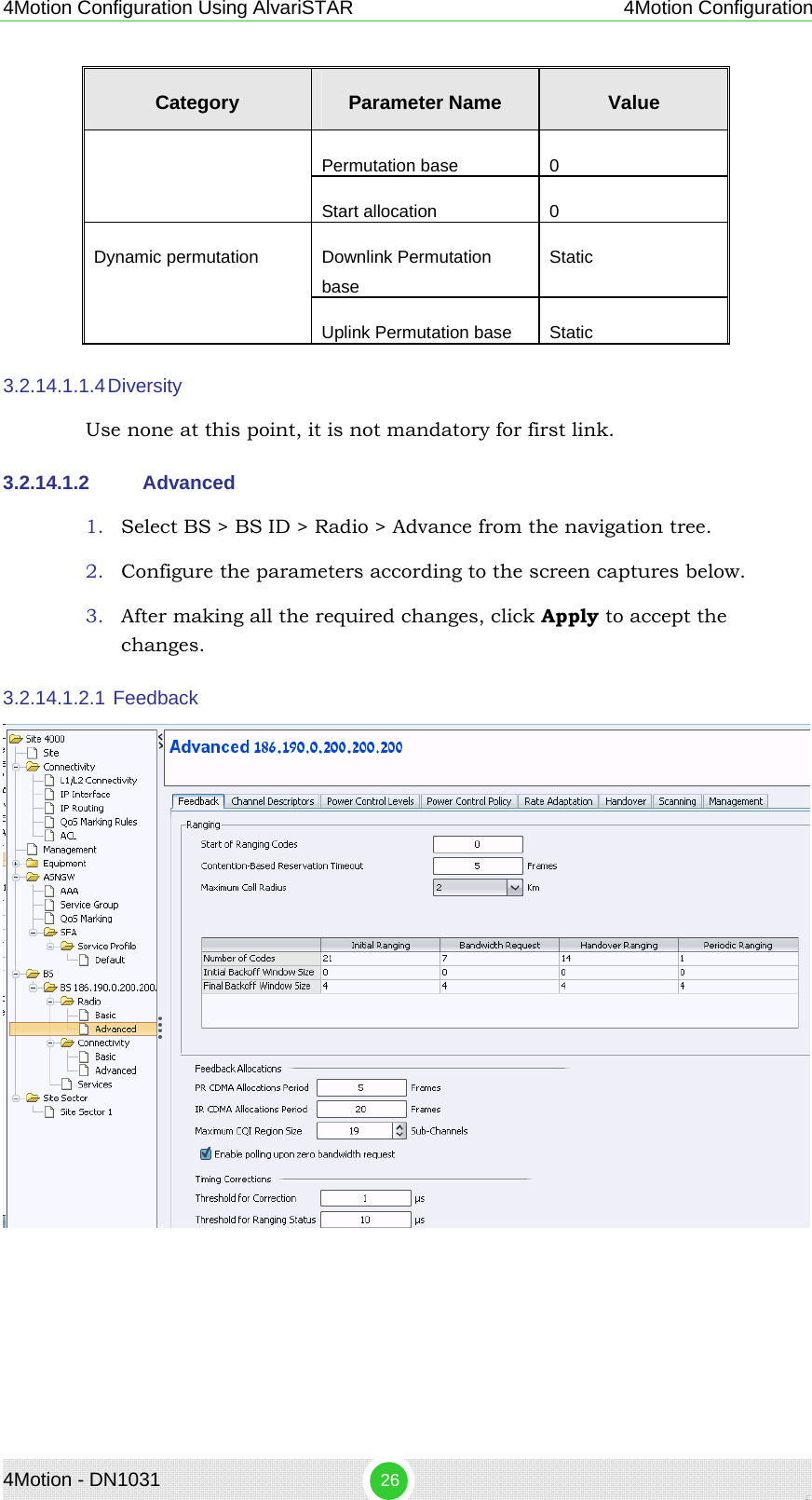
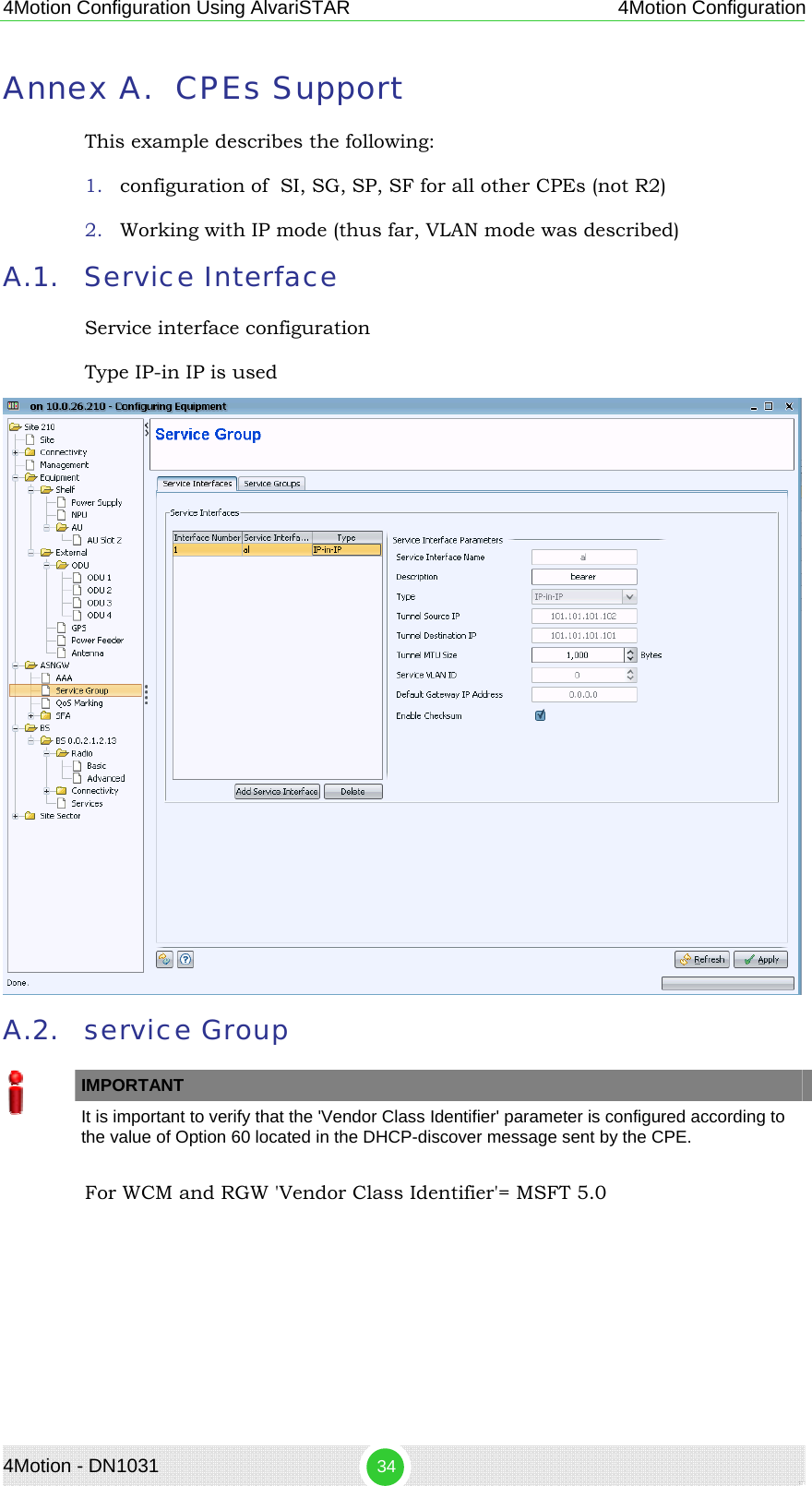
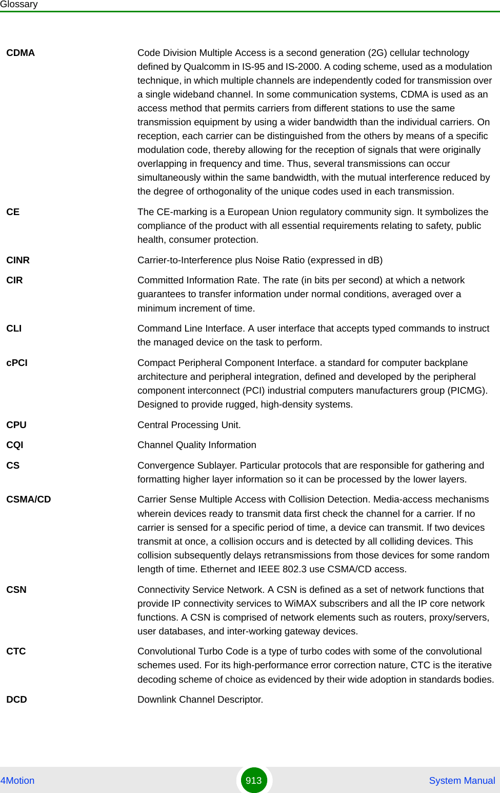
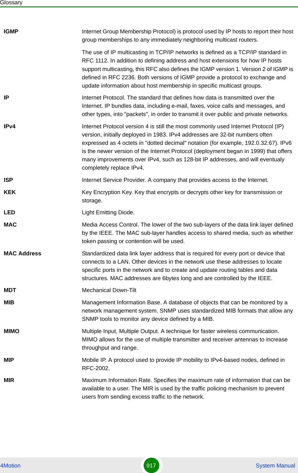
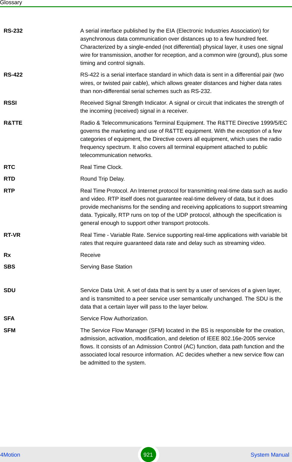
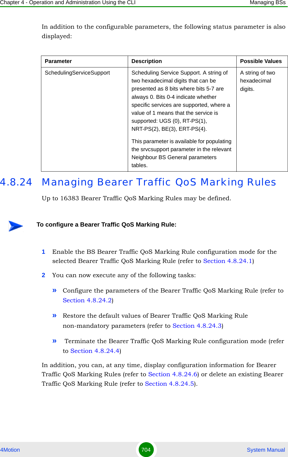
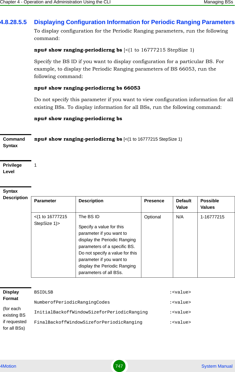
![Chapter 4 - Operation and Administration Using the CLI Managing BSs4Motion 689 System Manual4.8.20.2 Restoring the Default Values of Rate Adaptation ParametesTo restore the default values of some or all of the Rate Adaptation parameters, run the following command:npu(config-bs-66053)# no rateadapt-general [dl-basicrate] [ul-basicrate] [mincinr-qpsk-1by2-rep6] [mincinr-qpsk-1by2-rep4] [mincinr-qpsk-1by2-rep2 >] [mincinr-qpsk-1by2] [mincinr-qpsk-3by4] [mincinr-qam16-1by2] [mincinr-qam16-3by4] [mincinr-qam64-1by2] [mincinr-qam64-2by3] [mincinr-qam64-3by4] [mincinr-qam64-5by6]You can restore only some parameters to their default values by specifying only those parameters. For example, to restore only the ul-basicrate parameter to the default value, run the following command:npu(config-bs-66053)# no rateadapt-general ul-basicratemincinr-qam64-3by4 <(-20 to 30 StepSize 0.1)>The minimal CINR in dB Required to allow 64QAM 3/4 Uplink transmissions.Must be in the range from mincinr-qam64-2by3 to mincinr-qam64-5by6Optional -20 -20 to 30 in steps of 0.1mincinr-qam64-5by6 <(-20 to 30 StepSize 0.1)>The minimal CINR in dB Required to allow 64QAM 5/6 Uplink transmissions.Cannot be lower than mincinr-qam64-3by4Optional -20 -20 to 30 in steps of 0.1Command Modesbs configuration modeIMPORTANTWhen creating a new BS, at least one of the Rate Adaptation parameters must be configured explicitly (even if configured to the default value).](https://usermanual.wiki/Alvarion-Technologies/BMAX-OR-25.Manual-4/User-Guide-1114032-Page-8.png)
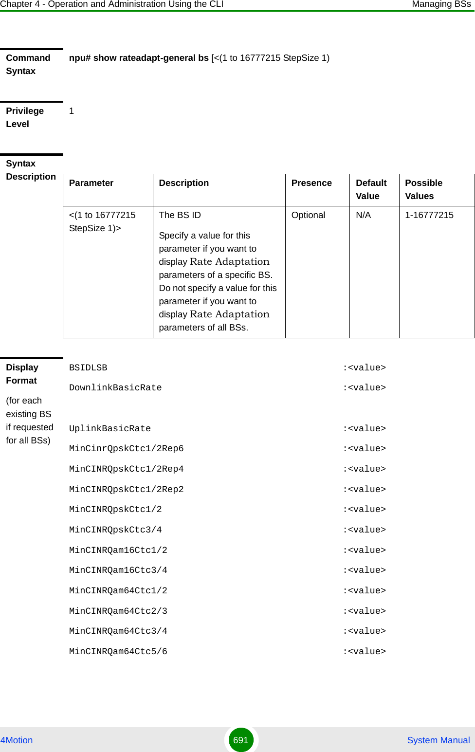
![Chapter 4 - Operation and Administration Using the CLI Managing BSs4Motion 690 System ManualThis parameter will be restored to its default value, while the other parameters will remain unchanged.To restore all Rate Adaptation parameters to their default value, run the following command:npu(config-bs-66053)# no rateadapt-general4.8.20.3 Displaying Configuration for Rate Adaptation ParametersTo display configuration information of Rate Adaptation parameters, run the following command:npu# show rateadapt-general bs [<(1 to 16777215 StepSize 1)Specify the BS ID if you want to display information for a particular BS. For example, to display the Rate Adaptation parameters of BS 66053, run the following command:npu# show rateadapt-general bs 66053Do not specify this parameter if you want to view information for all existing BSs. To display information for all BSs, run the following command:npu# show rateadapt-general bsNOTERefer to Section 4.8.20.1 for a description and default values of these parameters.Command Syntaxnpu(config-bs-66053)# rateadapt-general [dl-basicrate ] [ul-basicrate ] [mincinr-qpsk-1by2-rep6 ] [mincinr-qpsk-1by2-rep4 ] [mincinr-qpsk-1by2-rep2 > ] [mincinr-qpsk-1by2 ] [mincinr-qpsk-3by4 ] [mincinr-qam16-1by2 ] [mincinr-qam16-3by4 ] [mincinr-qam64-1by2 ] [mincinr-qam64-2by3 ] [mincinr-qam64-3by4 ] [mincinr-qam64-5by6 ]Privilege Level10Command Modesbs configuration mode](https://usermanual.wiki/Alvarion-Technologies/BMAX-OR-25.Manual-4/User-Guide-1114032-Page-9.png)
![Chapter 4 - Operation and Administration Using the CLI Managing BSs4Motion 692 System Manual4.8.21 Managing BS Bearer Interface ParametersAfter enabling the BS configuration mode, you can execute the following tasks:Configure one or more of the Bearer Interface parameters (refer to Section 4.8.21.1).Restore the default values of some or all of the Bearer Interface parameters (refer to Section 4.8.21.2).You can display configuration information for the Bearer Interface parameters of a selected or all existing BSs (refer to Section 4.8.21.3).4.8.21.1 Configuring Bearer Interface ParametersFrom the BS configuration mode, run the following command:npu(config-bs-66053)# bearer [ip-address <ip address>] [ip-subnetmask <ip address>] [dflt-gw <ip address>] [mtu-size <(1500 to 9000 StepSize 1)>] [linkusage-hardthrshld <(0 to100 StepSize 1)>]Command ModesGlobal command modeTo configure the Bearer Interface Parameters:Command Syntaxnpu(config-bs-66053)# bearer [ip-address <ip address> ] [ip-subnetmask <ip address> ] [dflt-gw <ip address> ] [mtu-size <(1500 to 9000 StepSize 1)> ] [linkusage-hardthrshld <(0 to100 StepSize 1)> ]Privilege Level10Syntax Description Parameter Description Presence Default Value Possible Values[ip-address <ip address> ]The IP address of the bearer interface of the BSMandatory when creating a new BSlN/A IP address](https://usermanual.wiki/Alvarion-Technologies/BMAX-OR-25.Manual-4/User-Guide-1114032-Page-11.png)
![Chapter 4 - Operation and Administration Using the CLI Managing BSs4Motion 693 System Manual4.8.21.2 Restoring the Default Values of Bearer Interface ParametesTo restore the default values of some or all of the Bearer Interface parameters, run the following command:npu(config-bs-66053)# no bearer [mtu-size] [linkusage-hardthrshld]You can restore only one parameter to the default values by specifying only that parameters. For example, to restore only the mtu-size parameter to the default value, run the following command:npu(config-bs-66053)# no bearer mtu-sizeThis parameter will be restored to its default value, while the other parameter will remain unchanged.To restore all Bearer Interface parameters to their default value, run the following command:npu(config-bs-66053)# no bearer[ip-subnetmask <ip address> ]The IP subnet mask of the bearer interface of the BSMandatory when creating a new BSlN/A Subnet mask[dflt-gw <ip address> ] The IP address of the default gateway of the bearer interface of the BSMandatory when creating a new BSlN/A IP address[mtu-size <(1500 to 9000 StepSize 1)> ]MTU size (in bytes) of the bearer interface of the BSOptional 1500 1500 - 9000[linkusage-hardthrshld <(0 to 100 StepSize 1)> ]The BS backplane usage hard limit threshold, in percecents. An alarm if sent if either uplink or downlink backplane link usage exceeds the threshold.Optional 80 0 - 100Command Modesbs configuration modeIMPORTANTWhen creating a new BS, the Bearer Interface mandatory parameters must be configured.](https://usermanual.wiki/Alvarion-Technologies/BMAX-OR-25.Manual-4/User-Guide-1114032-Page-12.png)
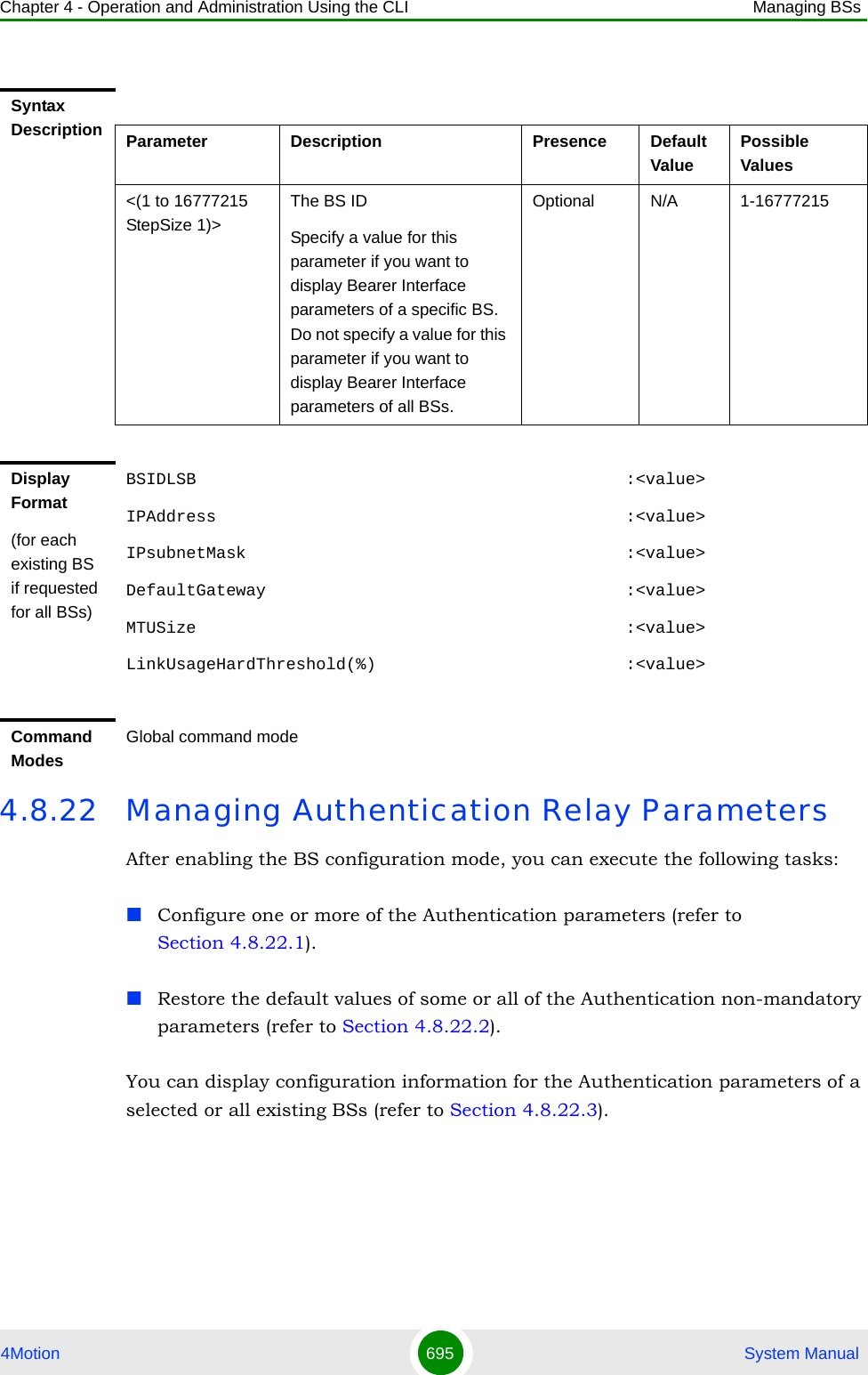
![Chapter 4 - Operation and Administration Using the CLI Managing BSs4Motion 694 System Manual4.8.21.3 Displaying Configuration Information for Bearer Interface ParametersTo display configuration information of Bearer Interface parameters, run the following command:npu# show bearer bs [<(1 to 16777215 StepSize 1)Specify the BS ID if you want to display information for a particular BS. For example, to display the Bearer Interface parameters of BS 66053, run the following command:npu# show bearer bs 66053Do not specify this parameter if you want to view information for all existing BSs. To display information for all BSs, run the following command:npu# show bearer bsNOTERefer to Section 4.8.21.1 for a description and default values of these parameters.Command Syntaxnpu(config-bs-66053)# no bearer [mtu-size ] [linkusage-hardthrshld ]Privilege Level10Command Modesbs configuration modeCommand Syntaxnpu# show bearer bs [<(1 to 16777215 StepSize 1)Privilege Level1](https://usermanual.wiki/Alvarion-Technologies/BMAX-OR-25.Manual-4/User-Guide-1114032-Page-13.png)
![Chapter 4 - Operation and Administration Using the CLI Managing BSs4Motion 696 System Manual4.8.22.1 Configuring Authentication ParametersFrom the BS configuration mode, run the following command:npu(config-bs-66053)# auth-general [dflt-auth-ip-address <ip address>] [suspendedeapprocthrshld <(0 to 10000 StepSize 1)>] [activemsthrshld <(0 to 1024 StepSize 1)>] [maxeaproundsthrshld <(0 to 100 StepSize 1)>] [nonauth-macctrlratethrshld <(0 to 120000 StepSize 1)>] [nonauth-pduratethrshld <(0 to 120000 StepSize 1)>]To configure the Authentication parameters:Command Syntaxnpu(config-bs-66053)# auth-general [dflt-auth-ip-address <ip address> ] [suspendedeapprocthrshld <(0 to 10000 StepSize 1)> ] [activemsthrshld <(0 to 1024 StepSize 1)> ] [maxeaproundsthrshld <(0 to 100 StepSize 1)> ] [nonauth-macctrlratethrshld <(0 to 120000 StepSize 1)> ] [nonauth-pduratethrshld <(0 to 120000 StepSize 1)> ]Privilege Level10Syntax Description Parameter Description Presence Default Value Possible Values[dflt-auth-ip-address <ip address> ]Identifier (IP address) of “default” authenticator ASN GW.Mandatory when creating a new BS.N/A IPv4 address[suspendedeapprocthrshld <(0 to 10000 StepSize 1)> ]Suspended EAP authentification process threshold. It is used to set an alarm.Optional 0 0 to 10000](https://usermanual.wiki/Alvarion-Technologies/BMAX-OR-25.Manual-4/User-Guide-1114032-Page-15.png)
![Chapter 4 - Operation and Administration Using the CLI Managing BSs4Motion 697 System Manual[activemsthrshld <(0 to 1024 StepSize 1)> ]Threshold for the number of MSs in active operation state (not Idle) served by the BS. Exceeding this threshold will set the alarm “Excessive MS number”.A value of 0 means that the alarm is disabled.Optional 0 0 to 1024[maxeaproundsthrshld <(0 to 100 StepSize 1)> ]Threshold for the number of EAP rounds in one direction in the same EAP session. When exceeding this threshold; alarm is set. May be used to protect the system from hazard EAP sessions with extreme number of messaging round trips. A value of "0" means the alarm is disabled.A value of 0 means that the alarm is disabled.Optional 0 0 to 100[nonauth-macctrlratethrshld <(0 to 120000 StepSize 1)> ]Threshold for alarm for exceeding non-authentic MAC control rate, in Kbps A value of 0 means that the alarm is disabled.Optional 0 0 to 120000[nonauth-pduratethrshld <(0 to 120000 StepSize 1)> ]Threshold for alarm for exceeding non-authentic PDU rate (in Kbps).A value of 0 means that the alarm is disabled.Optional 0 0 to 120000Command Modesbs configuration modeIMPORTANTWhen creating a new BS, the Authentication dflt-auth-ip-address mandatory parameter must be configured.](https://usermanual.wiki/Alvarion-Technologies/BMAX-OR-25.Manual-4/User-Guide-1114032-Page-16.png)
![Chapter 4 - Operation and Administration Using the CLI Managing BSs4Motion 698 System Manual4.8.22.2 Restoring the Default Values of Authentication ParametesTo restore the default values of some or all of the Authentication parameters, run the following command:npu(config-bs-66053)# no auth-general [suspendedeapprocthrshld] [activemsthrshld] [maxeaproundsthrshld] [nonauth-macctrlratethrshld] [nonauth-pduratethrshld]You can restore only some parameters to their default values by specifying only those parameters. For example, to restore only the activemsthrshld and maxeaproundsthrshld parameters to the default values, run the following command:npu(config-bs-66053)# no auth-general activemsthrshld maxeaproundsthrshldThese parameters will be restored to their default values, while the other parameters will remain unchanged.To restore all Authentication parameters to their default value, run the following command:npu(config-bs-66053)# no auth-general4.8.22.3 Displaying Configuration Information for Authentication ParametersTo display configuration information of Authentication parameters, run the following command:NOTERefer to Section 4.8.22.1 for a description and default values of these parameters.Command Syntaxnpu(config-bs-66053)# no auth-general [suspendedeapprocthrshld ] [activemsthrshld ] [maxeaproundsthrshld ] [nonauth-macctrlratethrshld ] [nonauth-pduratethrshld ]Privilege Level10Command Modesbs configuration mode](https://usermanual.wiki/Alvarion-Technologies/BMAX-OR-25.Manual-4/User-Guide-1114032-Page-17.png)
![Chapter 4 - Operation and Administration Using the CLI Managing BSs4Motion 700 System Manual4.8.23 Managing Handover Control ParametersAfter enabling the BS configuration mode, you can execute the following tasks:Configure one or more of the Handover Control parameters (refer to Section 4.8.23.1).Restore the default values of some or all of the Handover Control parameters (refer to Section 4.8.23.2).You can display configuration information for the Handover Control parameters of a selected or all existing BSs (refer to Section 4.8.23.3).4.8.23.1 Configuring Handover Control ParametersFrom the BS configuration mode, run the following command:npu(config-bs-66053)# hoctrl [enable-teksharing <hex-string>] [rtxtimer <(0 to 255 StepSize 1)>]To configure the Handover Control parameters:Command Syntaxnpu(config-bs-66053)# hoctrl [enable-teksharing <hex-string>] [rtxtimer <(0 to 255 StepSize 1)> ]Privilege Level10Syntax Description Parameter Description Presence Default Value Possible Values](https://usermanual.wiki/Alvarion-Technologies/BMAX-OR-25.Manual-4/User-Guide-1114032-Page-19.png)
![Chapter 4 - Operation and Administration Using the CLI Managing BSs4Motion 702 System Manual4.8.23.2 Restoring the Default Values of Handover Control ParametesTo restore the default values of some or all of the Handover Control parameters, run the following command:npu(config-bs-66053)# no hoctrl [enable-teksharing] [rtxtimer]You can restore only one parameter to the default values by specifying only that parameter. For example, to restore only the rtxtimer parameter to the default value, run the following command:npu(config-bs-66053)# no hoctrl rtxtimerThis parameter will be restored to its default value, while the other parameter will remain unchanged.To restore all Handover Control parameters to their default value, run the following command:npu(config-bs-66053)# no hoctrl4.8.23.3 Displaying Configuration and Status Information for Handover Control ParametersTo display configuration and status information of Handover Control parameters, run the following command:npu# show hoctrl bs [<(1 to 16777215 StepSize 1)NOTERefer to Section 4.8.23.1 for a description and default values of these parameters.Command Syntaxnpu(config-bs-66053)# no hoctrl [enable-teksharing ] [rtxtimer ]Privilege Level10Command Modesbs configuration mode](https://usermanual.wiki/Alvarion-Technologies/BMAX-OR-25.Manual-4/User-Guide-1114032-Page-21.png)
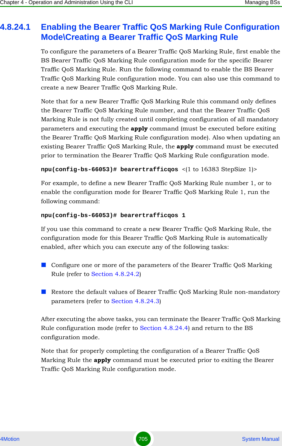
![Chapter 4 - Operation and Administration Using the CLI Managing BSs4Motion 706 System ManualFor example, to define Bearer Traffic QoS Marking Rule 1 for BS 66053, run the following command:npu(config-bs-66053)# bearertrafficqos 14.8.24.2 Configuring Bearer Traffic QoS Marking Rule ParametersTo configure the Bearer Traffic QoS Marking Rule parameters, run the following command:npu(config-bs-66053-bearertrafficqos-1)# mrkngrule [rule-status {Enable | Disable}] [rule-name <string (32)>] [srvcflow-datadeliverytype {uGS | bE | eRTVR | any}] [srvcflow-trafficpriority <(0 to 7 StepSize 1) | (255 to 255 StepSize 1)>] [srvcflow-mediaflowtype <string (32)>] [enable-srvcflow-mediaflowtype {TRUE | FALSE}] [outerdscp <(0 to 63 StepSize 1)>] [bp8021p <(0 to 7 StepSize 1)>]Command Syntaxnpu(config-bs-66053)# bearertrafficqos <(1 to 16383 StepSize 1)>Privilege Level10Syntax Description Parameter Description Presence Default Value Possible Valuesbearertrafficqos <(1 to 16383 StepSize 1)>The Bearer Traffic QoS Marking Rule numberMandatory 1 - 16383Command ModesBS configuration modeNOTEThe following examples are for BS Bearer Traffic QoS Marking Rule configuration mode for bs-66053, bearer traffic qos marking rule (bearertrafficqos)-1.IMPORTANTWhen creating a new Bearer Traffic QoS Marking Rule Rule, the mandatory parameters must be configured.](https://usermanual.wiki/Alvarion-Technologies/BMAX-OR-25.Manual-4/User-Guide-1114032-Page-25.png)
![Chapter 4 - Operation and Administration Using the CLI Managing BSs4Motion 707 System ManualCommand Syntaxnpu(config-bs-66053-bearertrafficqos-1)# mrkngrule [rule-status {Enable | Disable} ] [rule-name <string (32)> ] [srvcflow-datadeliverytype {uGS | bE | eRTVR | any} ] [srvcflow-trafficpriority <(0 to 7 StepSize 1) | (255 to 255 StepSize 1)> ] [srvcflow-mediaflowtype <string (32)> ] [enable-srvcflow-mediaflowtype {TRUE | FALSE} ] [outerdscp <(0 to 63 StepSize 1)> ] [bp8021p <(0 to 7 StepSize 1)> ]Privilege Level10Syntax Description Parameter Description Presence Default Value Possible Valuesrule-status {Enable | Disable}The Bearer Traffic QoS Marking Rule statusOptional Enable EnableDisablerule-name <string (32)>The Bearer Traffic QoS Marking Rule name (descriptor).Optional null A string of up to 32 characterssrvcflow-datadeliverytype {uGS | bE | eRTVR | any}Service Flow Type of data delivery services.Optional any uGSbEeRTVRanysrvcflow-trafficpriority <(0 to 7 StepSize 1) | (255 to 255 StepSize 1)>Service Flow Traffic Priority. A value of 255 means "ANY"Optional 255 0-7 or 255srvcflow-mediaflowtype <string (32)>One of key entries into the traffic marking rules table. Media Flow Type should be defined in ASN-GW or AAA server.Only relevant if enable-srvcflow-mediaflowtype (see below) is TRUE.Mandatory when creating a new rule (if relevant)N/A A string of up to 32 characters](https://usermanual.wiki/Alvarion-Technologies/BMAX-OR-25.Manual-4/User-Guide-1114032-Page-26.png)
![Chapter 4 - Operation and Administration Using the CLI Managing BSs4Motion 708 System Manual4.8.24.3 Restoring Default Values for Bearer Traffic QoS Marking Rule Configuration ParametersAfter enabling the Bearer Traffic QoS Marking Rule configuration mode you can restore the default values for non-mandatory parameters. To restore some or all of the Bearer Traffic QoS Marking Rule non-mandatory parameters to their default values, run the following command:npu(config-bs-66053-bearertrafficqos-1)# no mrkngrule [rule-status] [rule-name] [srvcflow-datadeliverytype [srvcflow-trafficpriority] [outerdscp] [bp8021p]You can restore only one or several parameters to the default values by specifying only those parameters. For example, to restore only the outerdscp to the default value, run the following command:npu(config-bs-66053-bearertrafficqos-1)# no mrkngrule outerdscpThe parameter will be restored to its default value, while the other parameters will remain unchanged.To restore all Bearer Traffic QoS Marking Rule non-mandatory parameters to their default value, run the following command:npu(config-bs-66053-bearertrafficqos-1)# no mrkngruleenable-srvcflow-mediaflowtype {TRUE | FALSE}If TRUE, the srvcflow-mediaflowtype (see above) will be considered. when looking for a match. If FALSE it will not be considered.Mandatory when creating a new ruleTRUEFALSEouterdscp <(0 to 63 StepSize 1)>DSCP value to be used for marking of outer IP header (IP/GRE).Optional 0 0 - 63bp8021p <(0 to 7 StepSize 1)>802.1p priority to be used for marking of trafficOptional 0 0 - 7Command Modesbs bearer traffic qos marking rule configuration mode NOTERefer to Section 4.8.24.2 for a description and default values of these parameters.](https://usermanual.wiki/Alvarion-Technologies/BMAX-OR-25.Manual-4/User-Guide-1114032-Page-27.png)
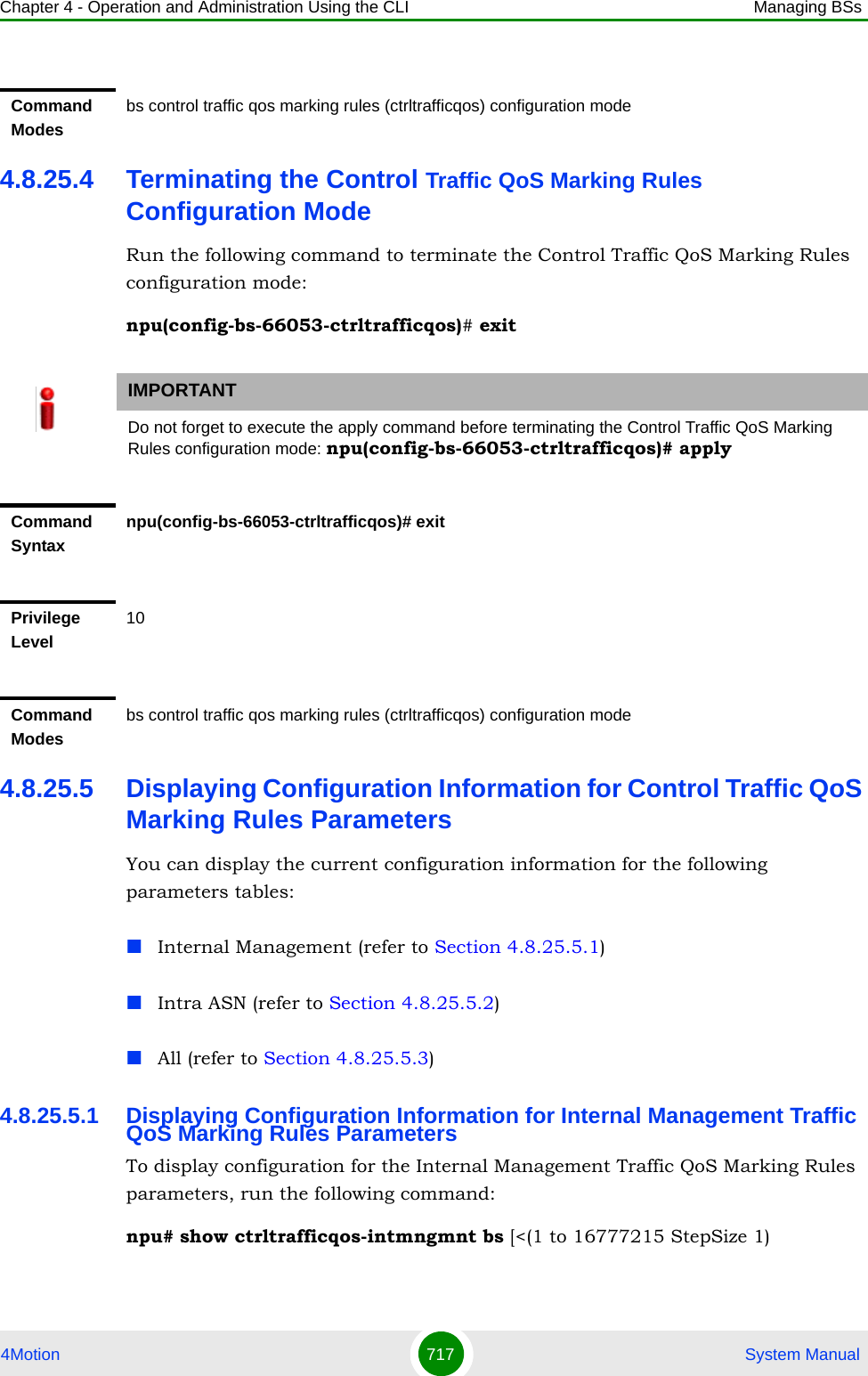
![Chapter 4 - Operation and Administration Using the CLI Managing BSs4Motion 709 System Manual4.8.24.4 Terminating the Bearer Traffic QoS Marking Rule Configuration ModeRun the following command to terminate the Bearer Traffic QoS Marking Rule configuration mode:npu(config-bs-66053-bearertrafficqos-1)# exit4.8.24.5 Deleting a Bearer Traffic QoS Marking RuleRun the following command from the BS configuration mode to delete a Bearer Traffic QoS Marking Rule:npu(config-bs 66053)# no bearertrafficqos <(1 to 16383 StepSize 1)> Command Syntaxnpu(config-bs-66053-bearertrafficqos-1)# no mrkngrule [rule-status ] [rule-name ] [srvcflow-datadeliverytype [srvcflow-trafficpriority ] [outerdscp ] [bp8021p ]Privilege Level10Command Modesbs bearer traffic qos marking rule configuration modeIMPORTANTDo not forget to execute the apply command before terminating the BS Bearer Traffic QoS Marking Rule configuration mode:npu(config-bs-66053-bearertrafficqos-1)# applyCommand Syntaxnpu(config-bs-66053-bearertrafficqos-1)# exitPrivilege Level10Command Modesbs bearer traffic qos marking rule configuration mode](https://usermanual.wiki/Alvarion-Technologies/BMAX-OR-25.Manual-4/User-Guide-1114032-Page-28.png)
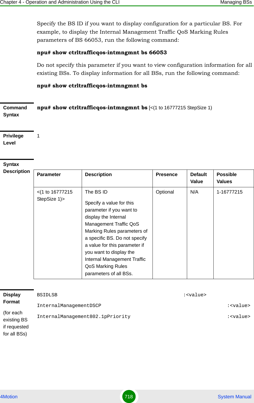
![Chapter 4 - Operation and Administration Using the CLI Managing BSs4Motion 710 System Manual4.8.24.6 Displaying Configuration Information for Bearer Traffic QoS Marking RulesTo display configuration for the parameters of a specific or all Bearer Traffic QoS Marking Rules, run the following command:npu# show bearertrafficqos bs [<(1 to 16777215 StepSize 1)> number <(1 to 16383 StepSize 1)>]Specify the BS ID and Bearer Traffic QoS Marking Rule number if you want to display configuration for a particular Bearer Traffic QoS Marking Rule. For example, to display the parameters of Bearer Traffic QoS Marking Rule 1 in BS 66053, run the following command:npu# show bearertrafficqos bs 66053 number 1Do not specify these parameters if you want to view configuration information for all existing Bearer Traffic QoS Marking Rules. To display information for all Bearer Traffic QoS Marking Rules, run the following command:npu# show bearertrafficqos bsCommand Syntaxnpu(config-bs 66053)# no bearertrafficqos <(1 to 16383 StepSize 1)> Privilege Level10Syntax Description Parameter Description Presence Default ValuePossible Values<(1 to 16383 StepSize 1)>The Bearer Traffic QoS Marking Rule number Mandatory N/A 1-16383Command Modesbs configuration modeCommand Syntaxnpu# show bearertrafficqos bs [<(1 to 16777215 StepSize 1)> number <(1 to 16383 StepSize 1)> ]](https://usermanual.wiki/Alvarion-Technologies/BMAX-OR-25.Manual-4/User-Guide-1114032-Page-29.png)
![Chapter 4 - Operation and Administration Using the CLI Managing BSs4Motion 711 System ManualPrivilege Level1Syntax Description Parameter Description Presence Default ValuePossible Values<(1 to 16777215 StepSize 1)>The BS ID Specify a value for this parameter if you want to display the parameters of a specific Bearer Traffic QoS Marking Rule. Do not specify a value for this parameter if you want to display the parameters of all Bearer Traffic QoS Marking Rules.Optional N/A 1-16777215number <(1 to 16383 StepSize 1)> ]The Bearer Traffic QoS Marking Rule number. To be used only if you want to display the parameters of a specific Bearer Traffic QoS Marking Rule.Optional N/A 1-16383Display Format(for each existing Service Mapping Rule if requested for all Service Mapping Rules)BSIDLSB :<value>RuleNumber :<value>RuleStatus :<value>RuleName :<value>ServiceFlowMediaFlowType :<value>ServiceFlowTrafficPriority(255meansany) :<value>ServiceFlowMediaFlowType :<value>EnableServiceFlowMediaFlowType :<value>OuterDSCP :<value>802.1pPriority :<value>Command ModesGlobal command mode](https://usermanual.wiki/Alvarion-Technologies/BMAX-OR-25.Manual-4/User-Guide-1114032-Page-30.png)
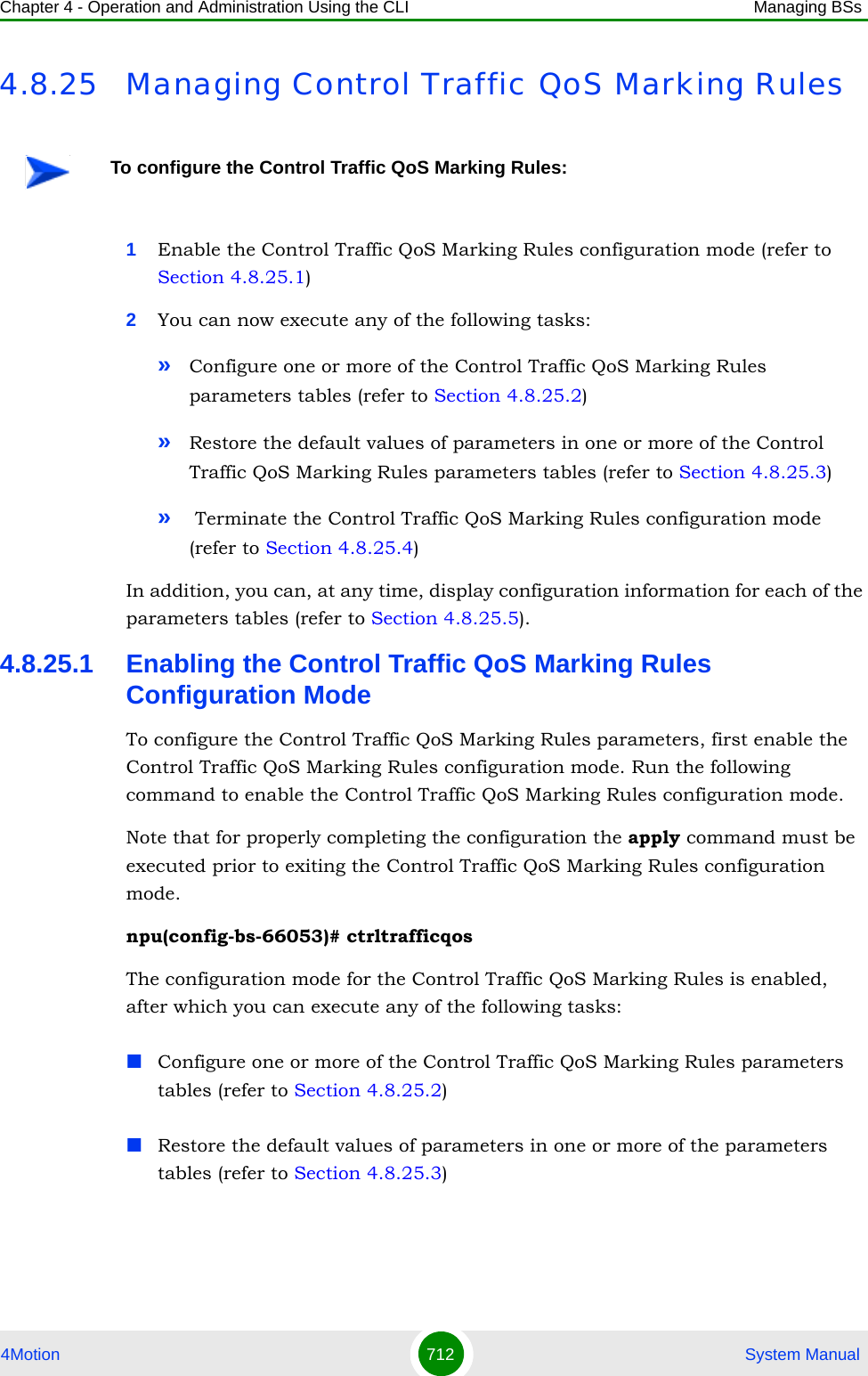
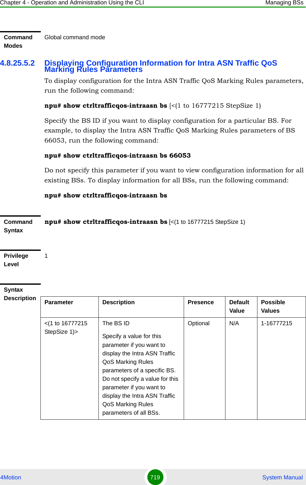
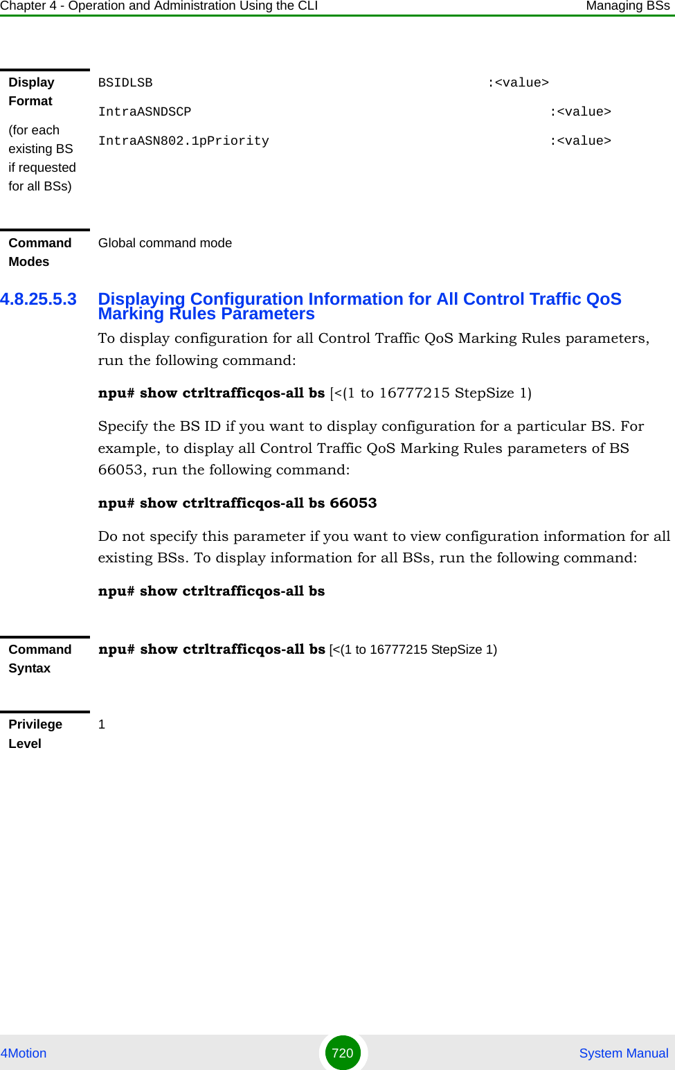
![Chapter 4 - Operation and Administration Using the CLI Managing BSs4Motion 713 System ManualAfter executing the above tasks, you can terminate the Control Traffic QoS Marking Rules configuration mode (refer to Section 4.8.25.4) and return to the BS configuration mode.Note that for properly completing the Control Traffic QoS Marking Rules configuration the apply command must be executed prior to exiting the Control Traffic QoS Marking Rules configuration mode.4.8.25.2 Configuring Control Traffic QoS Marking Rules ParametersAfter enabling the Control Traffic QoS Marking Rules configuration mode you can configure the following parameters tables:Internal Management (refer to Section 4.8.25.2.1)Intra ASN (refer to Section 4.8.25.2.2)4.8.25.2.1 Configuring Internal Management Traffic QoS Marking Rules ParametersTo configure the Internal Management Traffic QoS Marking Rules, run the following command:npu(config-bs-66053-ctrltrafficqos)# intmngmnt [dscp <(0 to 63 StepSize 1)>] [inter8021p <(0 to 7 StepSize 1)>]Command Syntaxnpu(config-bs-66053)# ctrltrafficqosPrivilege Level10Command Modesbs configuration modeIMPORTANTAfter completing the Control Traffic QoS Marking Rules configuration,do not forget to execute the apply command before exiting the Control Traffic QoS Marking Rules configuration mode:npu(config-bs-66053-ctrltrafficqos)# applyIMPORTANTWhen creating a new BS, at least one of the Internal Management Traffic QoS Marking Rules parameters must be configured explicitly (even if configured to the default value).](https://usermanual.wiki/Alvarion-Technologies/BMAX-OR-25.Manual-4/User-Guide-1114032-Page-32.png)
![Chapter 4 - Operation and Administration Using the CLI Managing BSs4Motion 714 System Manual4.8.25.2.2 Configuring the Intra ASN Traffic QoS Marking RulesTo configure the Intra ASN Traffic QoS Marking Rules parameters, run the following command:npu(config-bs-66053-ctrltrafficqos)# intraasn [dscp <(0 to 63 StepSize 1)>] [intra8021p <(0 to 7 StepSize 1)>]Command Syntaxnpu(config-bs-66053-ctrltrafficqos)# intmngmnt [dscp <(0 to 63 StepSize 1)> ] [inter8021p <(0 to 7 StepSize 1)> ]Privilege Level10Syntax Description Parameter Description Presence Default Value Possible Valuesdscp <(0 to 63 StepSize 1)>DSCP priority value to be used for marking of internal management trafficOptional 0 0 - 63inter8021p <(0 to 7 StepSize 1)>802.1p priority value to be used for marking of internal management trafficOptional 0 0 - 7Command Modesbs control traffic qos marking rules (ctrltrafficqos) configuration mode IMPORTANTWhen creating a new BS, at least one of the Intra ASN Traffic QoS Marking Rules parameters must be configured explicitly (even if configured to the default value).Command Syntaxnpu(config-bs-66053-ctrltrafficqos)# intraasn [dscp <(0 to 63 StepSize 1)> ] [intra8021p <(0 to 7 StepSize 1)> ]Privilege Level10](https://usermanual.wiki/Alvarion-Technologies/BMAX-OR-25.Manual-4/User-Guide-1114032-Page-33.png)
![Chapter 4 - Operation and Administration Using the CLI Managing BSs4Motion 715 System Manual4.8.25.3 Restoring Default Values for Control Traffic QoS Marking Rules Configuration ParametersAfter enabling the Control Traffic QoS Marking Rules configuration mode you can restore the default values for parameters in the following parameters tables:Internal Management (refer to Section 4.8.25.3.1)Intra ASN (refer to Section 4.8.25.3.2)4.8.25.3.1 Restoring the Default Values of Internal Management Traffic QoS Marking Rules ParametersTo restore one or all of the Internal Management Traffic QoS Marking Rules parameters to their default values, run the following command:npu(config-bs-66053-ctrltrafficqos)# no intmngmnt [dscp] [inter8021p]You can restore only one parameter to its default values by specifying only that parameter. For example, to restore only dscp to the default value, run the following command:npu(config-bs-66053-ctrltrafficqos)# no intmngmnt dscpThe parameter will be restored to its default value, while the other parameter will remain unchanged.To restore all Internal Management Traffic QoS Marking Rules parameters to their default value, run the following command:npu(config-bs-66053-ctrltrafficqos)# no intmngmntSyntax Description Parameter Description Presence Default Value Possible Valuesdscp <(0 to 63 StepSize 1)>DSCP priority value to be used for marking of intra-ASN (R8/R6) trafficOptional 0 0 - 63intra8021p <(0 to 7 StepSize 1)>802.1p priority value to be used for marking of intra-ASN (R8/R6) trafficOptional 0 0 - 7Command Modesbs control traffic qos marking rules (ctrltrafficqos) configuration mode](https://usermanual.wiki/Alvarion-Technologies/BMAX-OR-25.Manual-4/User-Guide-1114032-Page-34.png)
![Chapter 4 - Operation and Administration Using the CLI Managing BSs4Motion 716 System Manual4.8.25.3.2 Restoring the Default Values of Intra ASN Traffic QoS Marking Rules ParametersTo restore one or all of the Intra ASN Traffic QoS Marking Rules parameters to their default values, run the following command:npu(config-bs-66053-ctrltrafficqos)# no intraasn [dscp] [intra8021p]You can restore only one parameter to its default values by specifying only that parameter. For example, to restore only dscp to the default value, run the following command:npu(config-bs-66053-ctrltrafficqos)# no intraasn dscpThe parameter will be restored to its default value, while the other parameter will remain unchanged.To restore all Intra ASN Traffic QoS Marking Rules parameters to their default value, run the following command:npu(config-bs-66053-ctrltrafficqos)# no intraasnNOTERefer to Section 4.8.25.2.1 for a description and default values of these parameters.Command Syntaxnpu(config-bs-66053-ctrltrafficqos)# no intmngmnt [dscp ] [inter8021p ]Privilege Level10Command Modesbs control traffic qos marking rules (ctrltrafficqos) configuration mode NOTERefer to Section 4.8.25.2.2 for a description and default values of these parameters.Command Syntaxnpu(config-bs-66053-ctrltrafficqos)# no intraasn [dscp ] [intra8021p ]Privilege Level10](https://usermanual.wiki/Alvarion-Technologies/BMAX-OR-25.Manual-4/User-Guide-1114032-Page-35.png)
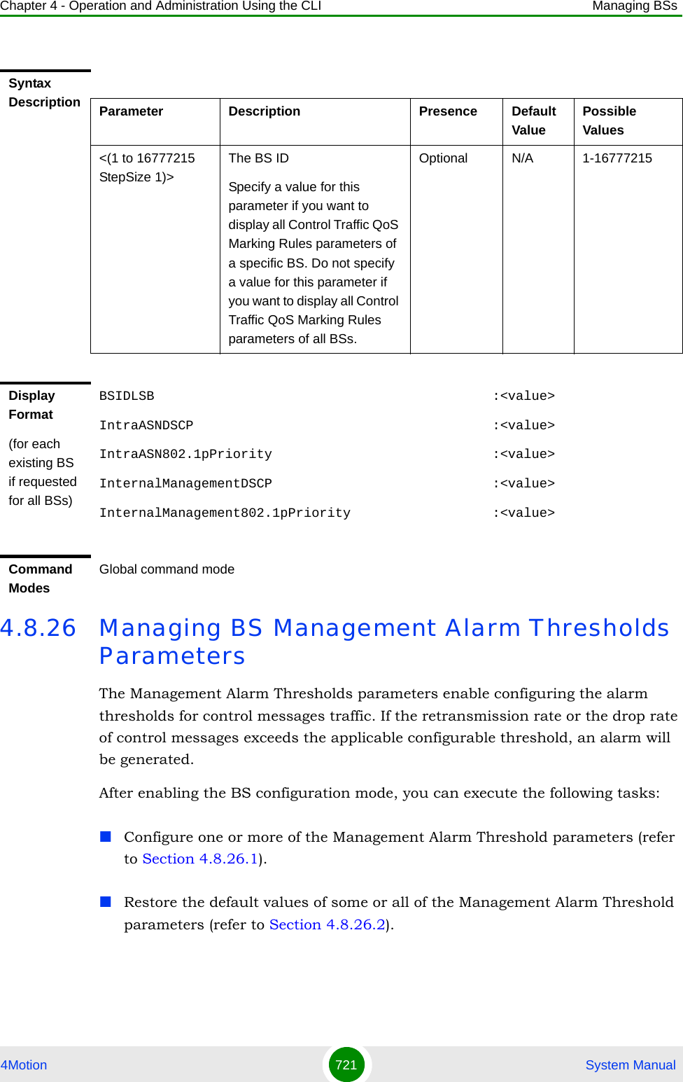
![Chapter 4 - Operation and Administration Using the CLI Managing BSs4Motion 722 System ManualYou can display configuration for the Management Alarm Threshold parameters of a selected or all existing BSs (refer to Section 4.8.26.3).4.8.26.1 Configuring Management Alarm Thresholds ParametersFrom the BS configuration mode, run the following command:npu(config-bs-66053)# mngmnt-alrmthrshld [retransmit-rate <(0 to 100 StepSize 1)>] [drop-rate <(0 to 100 StepSize 1)>]4.8.26.2 Restoring the Default Values of Management Alarm Thresholds ParametesTo restore the default values of some or all of the Management Alarm Thresholds parameters, run the following command:To configure the Management Alarm Thresholds parameters:Command Syntaxnpu(config-bs-66053)# mngmnt-alrmthrshld [retransmit-rate <(0 to 100 StepSize 1)> ] [drop-rate <(0 to 100 StepSize 1)> ]Privilege Level10Syntax Description Parameter Description Presence Default Value Possible Valuesretransmit-rate <(0 to 100 StepSize 1)>Alarm Threshold for retransmission rate of control messages (in %).Optional 30 0-100drop-rate <(0 to 100 StepSize 1)>Alarm Threshold for dropn rate of control messages (in %).Optional 10 0-100Command Modesbs configuration modeIMPORTANTWhen creating a new BS, at least one of the Management Alarm Thresholds parameters must be configured explicitly (even if configured to the default value).](https://usermanual.wiki/Alvarion-Technologies/BMAX-OR-25.Manual-4/User-Guide-1114032-Page-41.png)
![Chapter 4 - Operation and Administration Using the CLI Managing BSs4Motion 723 System Manualnpu(config-bs-66053)# no mngmnt-alrmthrshld [retransmit-rate] [drop-rate]You can restore only one parameter to the default value by specifying only that parameter. For example, to restore only the drop-rate parameter to the default value, run the following command:npu(config-bs-66053)# no mngmnt-alrmthrshld drop-rateThis parameter will be restored to its default value, while the other parameter will remain unchanged.To restore all Management Alarm Thresholds parameters to their default value, run the following command:npu(config-bs-66053)# no mngmnt-alrmthrshld4.8.26.3 Displaying Configuration Information for Management Alarm Thresholds ParametersTo display configuration information of Management Alarm Thresholds parameters, run the following command:npu# show mngmnt-alrmthrshld bs [<(1 to 16777215 StepSize 1)Specify the BS ID if you want to display information for a particular BS. For example, to display the Management Alarm Thresholds parameters of BS 66053, run the following command:npu# show mngmnt-alrmthrshld bs 66053Do not specify this parameter if you want to view information for all existing BSs. To display information for all BSs, run the following command:NOTERefer to Section 4.8.26.1 for a description and default values of these parameters.Command Syntaxnpu(config-bs-66053)# no mngmnt-alrmthrshld [retransmit-rate ] [drop-rate ]Privilege Level10Command Modesbs configuration mode](https://usermanual.wiki/Alvarion-Technologies/BMAX-OR-25.Manual-4/User-Guide-1114032-Page-42.png)
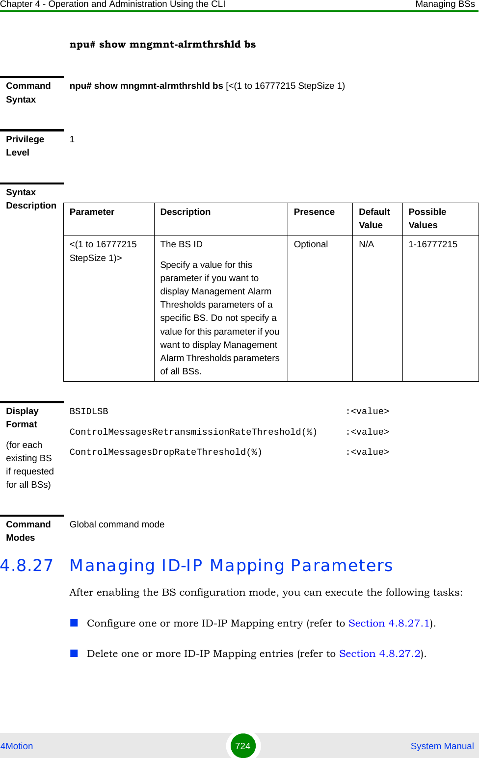
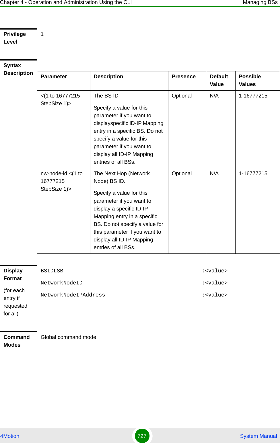
![Chapter 4 - Operation and Administration Using the CLI Managing BSs4Motion 725 System ManualYou can display configuration information for the ID-IP Mapping of a selected or all existing BSs (refer to Section 4.8.27.3).4.8.27.1 Configuring ID-IP Mapping EntriesFrom the BS configuration mode, run the following command:npu(config-bs-66053)# idip <(1 to 16777215 StepSize 1)> [nw-node-ip <ip address>]4.8.27.2 Deleting an ID-IP Mapping EntryRun the following command from the BS configuration mode to delete an ID-IP Mapping entry:npu(config-bs 66053)# no idip <(1 to 16777215 StepSize 1)> To configure ID-IP Mapping entries:Command Syntaxnpu(config-bs-66053)# idip <(1 to 16777215 StepSize 1)> [nw-node-ip <ip address> ]Privilege Level10Syntax Description Parameter Description Presence Default Value Possible Values<(1 to 16777215 StepSize 1)>The Next Hop (Network Node) BS IDMandatory N/A 1 - 16777215nw-node-ip <ip address> The Next Hop (Network Node) BS IP AddressMandatory N/A IP addressCommand Modesbs configuration modeIMPORTANTWhen creating a new BS, at least one ID-IP Mapping entry must be configured.](https://usermanual.wiki/Alvarion-Technologies/BMAX-OR-25.Manual-4/User-Guide-1114032-Page-44.png)
![Chapter 4 - Operation and Administration Using the CLI Managing BSs4Motion 726 System Manual4.8.27.3 Displaying Configuration Information for ID-IP Mapping EntriesTo display configuration information of ID-IP Mapping entries, run the following command:npu# show idip bs [<(1 to 16777215 StepSize 1)> nw-node-id <(1 to 16777215 StepSize 1)>]Specify the BS ID and Next Hop (Network Node) BS ID (nw-node-id) if you want to display information for a particular ID-IP Mapping entry. For example, to display the ID-IP Mapping of BS 66053 and Network Node 66055, run the following command:npu# show idip bs 66053 nw-node-id 66055Do not specify these parameters if you want to view information of ID-IP Mapping entries in all existing BSs. To display information for all BSs, run the following command:npu# show idip bsCommand Syntaxnpu(config-bs 66053)# no idip <(1 to 16777215 StepSize 1)> Privilege Level10Syntax Description Parameter Description Presence Default ValuePossible Values<(1 to 16777215 StepSize 1)>The Next Hop (Network Node) BS IDMandatory N/A 1 - 16777215Command Modesbs configuration modeCommand Syntaxnpu# show idip bs [<(1 to 16777215 StepSize 1)> nw-node-id <(1 to 16777215 StepSize 1)> ]](https://usermanual.wiki/Alvarion-Technologies/BMAX-OR-25.Manual-4/User-Guide-1114032-Page-45.png)
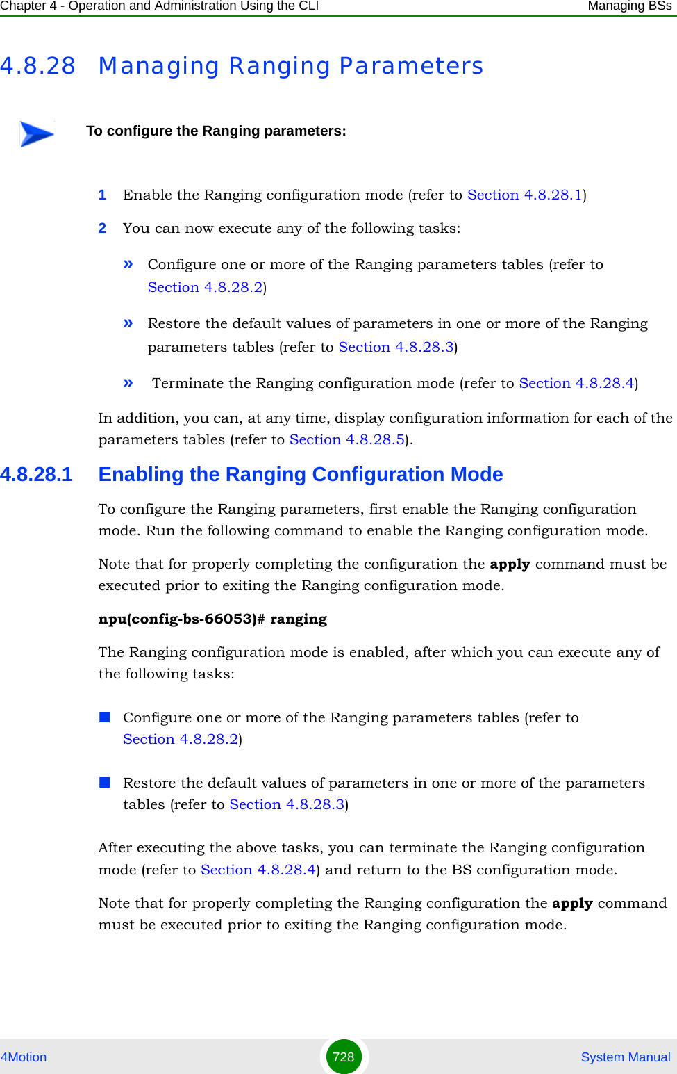
![Chapter 4 - Operation and Administration Using the CLI Managing BSs4Motion 729 System Manual4.8.28.2 Configuring Ranging ParametersAfter enabling the Ranging configuration mode you can configure the following parameters tables:General (refer to Section 4.8.28.2.1)Bandwidth Request (refer to Section 4.8.28.2.2)Handover Ranging (refer to Section 4.8.28.2.3)Initial Ranging (refer to Section 4.8.28.2.4)Periodic Ranging (refer to Section 4.8.28.2.5)Timing Correction (refer to Section 4.8.28.2.6)4.8.28.2.1 Configuring Ranging General ParametersTo configure the Ranging General parameters, run the following command:npu(config-bs-66053-ranging)# general [start-of-rng-codes <(0 to 255 StepSize 1)>] [contbased-rsrvtimeout <(0 to 255 StepSize 1)>] [max-cellradius {one | two | four | eight | fifteen | twentyThree | thirty}]Command Syntaxnpu(config-bs-66053)# rangingPrivilege Level10Command Modesbs configuration modeIMPORTANTAfter completing the Ranging configuration,do not forget to execute the apply command before exiting the Ranging configuration mode:npu(config-bs-66053-ranging)# applyIMPORTANTWhen creating a new BS, at least one of the Ranging General parameters must be configured explicitly (even if configured to the default value).](https://usermanual.wiki/Alvarion-Technologies/BMAX-OR-25.Manual-4/User-Guide-1114032-Page-48.png)
![Chapter 4 - Operation and Administration Using the CLI Managing BSs4Motion 730 System ManualCommand Syntaxnpu(config-bs-66053-ranging)# general [start-of-rng-codes <(0 to 255 StepSize 1)> ] [contbased-rsrvtimeout <(0 to 255 StepSize 1)> ] [max-cellradius {one | two | four | eight | fifteen | twentyThree | thirty} ]Privilege Level10Syntax Description Parameter Description Presence Default Value Possible Valuesstart-of-rng-codes <(0 to 255 StepSize 1)>Start of Ranging Codes: The starting number S of the group of codes used for this uplinkNote that the sum of initial ranging codes, periodic ranging codes, bandwidth request codes, handover ranging codes and start of ranging codes should be equal to or less than 256.Optional 0 0 - 255contbased-rsrvtimeout <(0 to 255 StepSize 1)>Contention-Based Reservation Timeout (in frames). The number of UL-MAPs to receive before contention-based reservation is attempted again for the same connection.Optional 5 0 - 255max-cellradius {one | two | four | eight | fifteen | twentyThree | thirty}The Maximum Cell Radius (in km)Optional two onetwofoureightfifteentwentyThreethirty](https://usermanual.wiki/Alvarion-Technologies/BMAX-OR-25.Manual-4/User-Guide-1114032-Page-49.png)
![Chapter 4 - Operation and Administration Using the CLI Managing BSs4Motion 731 System Manual4.8.28.2.2 Configuring Ranging Bandwidth Request ParametersTo configure the Ranging Bandwidth Request parameters, run the following command:npu(config-bs-66053-ranging)# bwreq [codes <(0 to 255 StepSize 1)>] [init-backoff-window-size <(0 to 15 StepSize 1)>] [final-backoff-window-size <(0 to 15 StepSize 1)>]Command Modesbs ranging configuration mode IMPORTANTWhen creating a new BS, at least one of the Ranging Bandwidth Request parameters must be configured explicitly (even if configured to the default value).Command Syntaxnpu(config-bs-66053-ranging)# bwreq [codes <(0 to 255 StepSize 1)> ] [init-backoff-window-size <(0 to 15 StepSize 1)> ] [final-backoff-window-size <(0 to 15 StepSize 1)> ]Privilege Level10Syntax Description Parameter Description Presence Default Value Possible Valuescodes <(0 to 255 StepSize 1)>Number of Bandwidth Request Codes.Note that the sum of initial ranging codes, periodic ranging codes, bandwidth request codes, handover ranging codes and start of ranging codes should be equal to or less than 256.Optional 14 0 - 255init-backoff-window-size <(0 to 15 StepSize 1)>Initial backoff window size for contention BW requests; expressed as a power of 2.Optional 0 0 - 15](https://usermanual.wiki/Alvarion-Technologies/BMAX-OR-25.Manual-4/User-Guide-1114032-Page-50.png)
![Chapter 4 - Operation and Administration Using the CLI Managing BSs4Motion 732 System Manual4.8.28.2.3 Configuring Handover Ranging ParametersTo configure the Handover Ranging parameters, run the following command:npu(config-bs-66053-ranging)# horng [codes <(0 to 255 StepSize 1)>] [init-backoff-window-size <(0 to 15 StepSize 1)>] [final-backoff-window-size <(0 to 15 StepSize 1)>]final-backoff-window-size <(0 to 15 StepSize 1)>Final backoff window size for contention BW requests; expressed as a power of 2.Cannot higher than or equal to bwreq init-backoff-window-size.Optional 4 0 - 15Command Modesbs ranging configuration mode IMPORTANTWhen creating a new BS, at least one of the Handover Ranging parameters must be configured explicitly (even if configured to the default value).Command Syntaxnpu(config-bs-66053-ranging)# horng [codes <(0 to 255 StepSize 1)> ] [init-backoff-window-size <(0 to 15 StepSize 1)> ] [final-backoff-window-size <(0 to 15 StepSize 1)> ]Privilege Level10Syntax Description Parameter Description Presence Default Value Possible Valuescodes <(0 to 255 StepSize 1)>Number of Handover Ranging CDMA Codes.Note that the sum of initial ranging codes, periodic ranging codes, bandwidth request codes, handover ranging codes and start of ranging codes should be equal to or less than 256.Optional 14 0 - 255](https://usermanual.wiki/Alvarion-Technologies/BMAX-OR-25.Manual-4/User-Guide-1114032-Page-51.png)
![Chapter 4 - Operation and Administration Using the CLI Managing BSs4Motion 733 System Manual4.8.28.2.4 Configuring Initial Ranging ParametersTo configure the Initial Ranging parameters, run the following command:npu(config-bs-66053-ranging)# initrng [codes <(0 to 255 StepSize 1)>] [init-backoff-window-size <(0 to 15 StepSize 1)>] [final-backoff-window-size <(0 to 15 StepSize 1)>]init-backoff-window-size <(0 to 15 StepSize 1)>Initial backoff window size for handover ranging contention ; expressed as a power of 2.Optional 0 0 - 15final-backoff-window-size <(0 to 15 StepSize 1)>Final backoff window size for handover ranging contention; expressed as a power of 2.Cannot higher than or equal to horng init-backoff-window-size.Optional 4 0 - 15Command Modesbs ranging configuration mode IMPORTANTWhen creating a new BS, at least one of the Initial Ranging parameters must be configured explicitly (even if configured to the default value).Command Syntaxnpu(config-bs-66053-ranging)# initrng [codes <(0 to 255 StepSize 1)> ] [init-backoff-window-size <(0 to 15 StepSize 1)> ] [final-backoff-window-size <(0 to 15 StepSize 1)> ]Privilege Level10Syntax Description Parameter Description Presence Default Value Possible Values](https://usermanual.wiki/Alvarion-Technologies/BMAX-OR-25.Manual-4/User-Guide-1114032-Page-52.png)
![Chapter 4 - Operation and Administration Using the CLI Managing BSs4Motion 734 System Manual4.8.28.2.5 Configuring Periodic Ranging ParametersTo configure the Periodic Ranging parameters, run the following command:npu(config-bs-66053-ranging)# periodicrng [codes <(0 to 255 StepSize 1)>] [init-backoff-window-size <(0 to 15 StepSize 1)>] [final-backoff-window-size <(0 to 15 StepSize 1)>]codes <(0 to 255 StepSize 1)>Number of Initial Ranging CDMA Codes.Note that the sum of initial ranging codes, periodic ranging codes, bandwidth request codes, handover ranging codes and start of ranging codes should be equal to or less than 256.Optional 14 0 - 255init-backoff-window-size <(0 to 15 StepSize 1)>Initial backoff window size for initial ranging contention ; expressed as a power of 2.Optional 0 0 - 15final-backoff-window-size <(0 to 15 StepSize 1)>Final backoff window size for initial ranging contention; expressed as a power of 2.Cannot higher than or equal to initrng init-backoff-window-size.Optional 4 0 - 15Command Modesbs ranging configuration mode IMPORTANTWhen creating a new BS, at least one of the Periodic Ranging parameters must be configured explicitly (even if configured to the default value).Command Syntaxnpu(config-bs-66053-ranging)# periodicrng [codes <(0 to 255 StepSize 1)> ] [init-backoff-window-size <(0 to 15 StepSize 1)> ] [final-backoff-window-size <(0 to 15 StepSize 1)> ]Privilege Level10](https://usermanual.wiki/Alvarion-Technologies/BMAX-OR-25.Manual-4/User-Guide-1114032-Page-53.png)
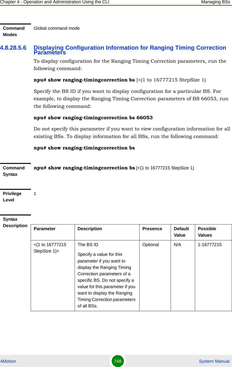
![Chapter 4 - Operation and Administration Using the CLI Managing BSs4Motion 735 System Manual4.8.28.2.6 Configuring Ranging Timing Correction ParametersTo configure the Timing Correction parameters, run the following command:npu(config-bs-66053-ranging)# timingcorrection [thrshld-correction <(0 to 250 StepSize 0.1)>] [thrshld-rngstatus <(0 to 250 StepSize 0.1)>]Syntax Description Parameter Description Presence Default Value Possible Valuescodes <(0 to 255 StepSize 1)>Number of Periodic Ranging CDMA Codes.Note that the sum of initial ranging codes, periodic ranging codes, bandwidth request codes, handover ranging codes and start of ranging codes should be equal to or less than 256.Optional 0 0 - 255init-backoff-window-size <(0 to 15 StepSize 1)>Initial backoff window size for periodic ranging contention ; expressed as a power of 2.Optional 0 0 - 15final-backoff-window-size <(0 to 15 StepSize 1)>Final backoff window size for periodic ranging contention; expressed as a power of 2.Cannot higher than or equal to periodicrng init-backoff-window-size.Optional 4 0 - 15Command Modesbs ranging configuration mode IMPORTANTWhen creating a new BS, at least one of the Timing Correction parameters must be configured explicitly (even if configured to the default value).Command Syntaxnpu(config-bs-66053-ranging)# timingcorrection [thrshld-correction <(0 to 250 StepSize 0.1)> ] [thrshld-rngstatus <(0 to 250 StepSize 0.1)> ]Privilege Level10](https://usermanual.wiki/Alvarion-Technologies/BMAX-OR-25.Manual-4/User-Guide-1114032-Page-54.png)
![Chapter 4 - Operation and Administration Using the CLI Managing BSs4Motion 736 System Manual4.8.28.3 Restoring Default Values for Ranging Configuration ParametersAfter enabling the Ranging configuration mode you can restore the default values for parameters in the following parameters tables:General (refer to Section 4.8.28.3.1)Bandwidth Request (refer to Section 4.8.28.3.2)Handover Ranging (refer to Section 4.8.28.3.3)Initial Ranging (refer to Section 4.8.28.3.4)Periodic Ranging (refer to Section 4.8.28.3.5)Timing Correction (refer to Section 4.8.28.3.6)4.8.28.3.1 Restoring the Default Values of Ranging General ParametersTo restore one or all of the Ranging General parameters to their default values, run the following command:npu(config-bs-66053-ranging)# no general [start-of-rng-codes] [contbased-rsrvtimeout] [max-cellradius]You can restore only some parameters to their default values by specifying only those parameters. For example, to restore only max-cellradius to the default value, run the following command:Syntax Description Parameter Description Presence Default Value Possible Valuesthrshld-correction <(0 to 250 StepSize 0.1)>Timing correction range threshold (in microseconds) below which corrections aren't made.Optional 1 0 - 250 in steps of 0.1thrshld-rngstatus <(0 to 250 StepSize 0.1)>Timing correction range threshold (in microseconds) below which the ranging status is success and above which the ranging status is continueOptional 10 0 - 250 in steps of 0.1Command Modesbs ranging configuration mode](https://usermanual.wiki/Alvarion-Technologies/BMAX-OR-25.Manual-4/User-Guide-1114032-Page-55.png)
![Chapter 4 - Operation and Administration Using the CLI Managing BSs4Motion 737 System Manualnpu(config-bs-66053-ranging)# no general max-cellradiusThe parameter will be restored to its default value, while the other parameters will remain unchanged.To restore all Ranging General parameters to their default value, run the following command:npu(config-bs-66053-ranging)# no general4.8.28.3.2 Restoring the Default Values of Ranging Bandwidth Request ParametersTo restore one or all of the Ranging Bandwidth Request parameters to their default values, run the following command:npu(config-bs-66053-ranging)# no bwreq [codes] [init-backoff-window-size] [final-backoff-window-size]You can restore only some parameters to their default values by specifying only those parameters. For example, to restore only the codes parameter to the default value, run the following command:npu(config-bs-66053-ranging)# no bwreq codesThe parameter will be restored to its default value, while the other parameters will remain unchanged.To restore all Ranging Bandwidth Request parameters to their default value, run the following command:npu(config-bs-66053-ranging)# no bwreqNOTERefer to Section 4.8.28.2.1 for a description and default values of these parameters.Command Syntaxnpu(config-bs-66053-ranging)# no general [start-of-rng-codes ] [contbased-rsrvtimeout ] [max-cellradius ]Privilege Level10Command Modesbs ranging configuration mode](https://usermanual.wiki/Alvarion-Technologies/BMAX-OR-25.Manual-4/User-Guide-1114032-Page-56.png)
![Chapter 4 - Operation and Administration Using the CLI Managing BSs4Motion 738 System Manual4.8.28.3.3 Restoring the Default Values of Handover Ranging ParametersTo restore one or all of the Handover Ranging parameters to their default values, run the following command:npu(config-bs-66053-ranging)# no horng [codes] [init-backoff-window-size] [final-backoff-window-size]You can restore only some parameters to their default values by specifying only those parameters. For example, to restore only the codes parameter to the default value, run the following command:npu(config-bs-66053-ranging)# no horng codesThe parameter will be restored to its default value, while the other parameters will remain unchanged.To restore all Handover Ranging parameters to their default value, run the following command:npu(config-bs-66053-ranging)# no horngNOTERefer to Section 4.8.28.2.2 for a description and default values of these parameters.Command Syntaxnpu(config-bs-66053-ranging)# no bwreq [codes ] [init-backoff-window-size ] [final-backoff-window-size ]Privilege Level10Command Modesbs ranging configuration mode NOTERefer to Section 4.8.28.2.3 for a description and default values of these parameters.Command Syntaxnpu(config-bs-66053-ranging)# no horng [codes ] [init-backoff-window-size ] [final-backoff-window-size ]](https://usermanual.wiki/Alvarion-Technologies/BMAX-OR-25.Manual-4/User-Guide-1114032-Page-57.png)
![Chapter 4 - Operation and Administration Using the CLI Managing BSs4Motion 739 System Manual4.8.28.3.4 Restoring the Default Values of Initial Ranging ParametersTo restore one or all of the Initial Ranging parameters to their default values, run the following command:npu(config-bs-66053-ranging)# no initrng [codes] [init-backoff-window-size] [final-backoff-window-size]You can restore only some parameters to their default values by specifying only those parameters. For example, to restore only the codes parameter to the default value, run the following command:npu(config-bs-66053-ranging)# no initrng codesThe parameter will be restored to its default value, while the other parameters will remain unchanged.To restore all Initial Ranging parameters to their default value, run the following command:npu(config-bs-66053-ranging)# no initrng4.8.28.3.5 Restoring the Default Values of Periodic Ranging ParametersTo restore one or all of the Periodic Ranging parameters to their default values, run the following command:Privilege Level10Command Modesbs ranging configuration mode NOTERefer to Section 4.8.28.2.4 for a description and default values of these parameters.Command Syntaxnpu(config-bs-66053-ranging)# no initrng [codes ] [init-backoff-window-size ] [final-backoff-window-size ]Privilege Level10Command Modesbs ranging configuration mode](https://usermanual.wiki/Alvarion-Technologies/BMAX-OR-25.Manual-4/User-Guide-1114032-Page-58.png)
![Chapter 4 - Operation and Administration Using the CLI Managing BSs4Motion 740 System Manualnpu(config-bs-66053-ranging)# no periodicrng [codes] [init-backoff-window-size] [final-backoff-window-size]You can restore only some parameters to their default values by specifying only those parameters. For example, to restore only the codes parameter to the default value, run the following command:npu(config-bs-66053-ranging)# no periodicrng codesThe parameter will be restored to its default value, while the other parameters will remain unchanged.To restore all Periodic Ranging parameters to their default value, run the following command:npu(config-bs-66053-ranging)# no periodicrng4.8.28.3.6 Restoring the Default Values of Ranging Timing Correction ParametersTo restore one or all of the Ranging Timing Correction parameters to their default values, run the following command:npu(config-bs-1-ranging)# no timingcorrection [thrshld-correction] [thrshld-rngstatus]You can restore only one parameter to the default values by specifying only that parameters. For example, to restore only the thrshld-correction parameter to the default value, run the following command:npu(config-bs-66053-ranging)# no timingcorrection thrshld-correctionNOTERefer to Section 4.8.28.2.5 for a description and default values of these parameters.Command Syntaxnpu(config-bs-66053-ranging)# no periodicrng [codes ] [init-backoff-window-size ] [final-backoff-window-size ]Privilege Level10Command Modesbs ranging configuration mode](https://usermanual.wiki/Alvarion-Technologies/BMAX-OR-25.Manual-4/User-Guide-1114032-Page-59.png)
![Chapter 4 - Operation and Administration Using the CLI Managing BSs4Motion 741 System ManualThe parameter will be restored to its default value, while the other parameter will remain unchanged.To restore all Ranging Timing Correction parameters to their default value, run the following command:npu(config-bs-66053-ranging)# no timingcorrection4.8.28.4 Terminating the Ranging Configuration ModeRun the following command to terminate the Ranging configuration mode:npu(config-bs-66053-ranging)# exitNOTERefer to Section 4.8.28.2.6 for a description and default values of these parameters.Command Syntaxnpu(config-bs-1-ranging)# no timingcorrection [thrshld-correction ] [thrshld-rngstatus ]Privilege Level10Command Modesbs ranging configuration mode IMPORTANTDo not forget to execute the apply command before terminating the CRanging configuration mode: npu(config-bs-66053-ranging)# applyCommand Syntaxnpu(config-bs-66053-ranging)# exitPrivilege Level10Command Modesbs ranging configuration mode](https://usermanual.wiki/Alvarion-Technologies/BMAX-OR-25.Manual-4/User-Guide-1114032-Page-60.png)
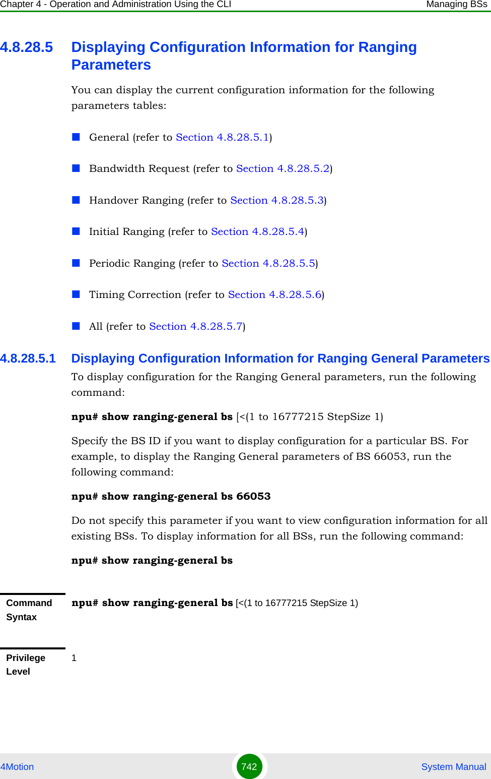
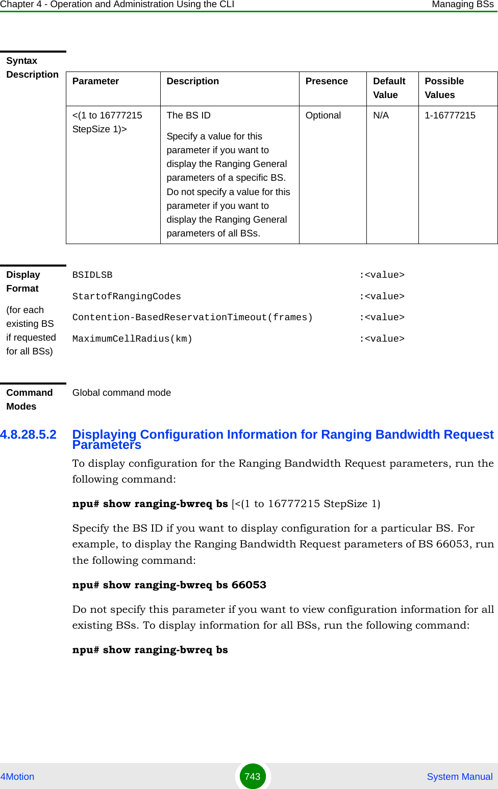
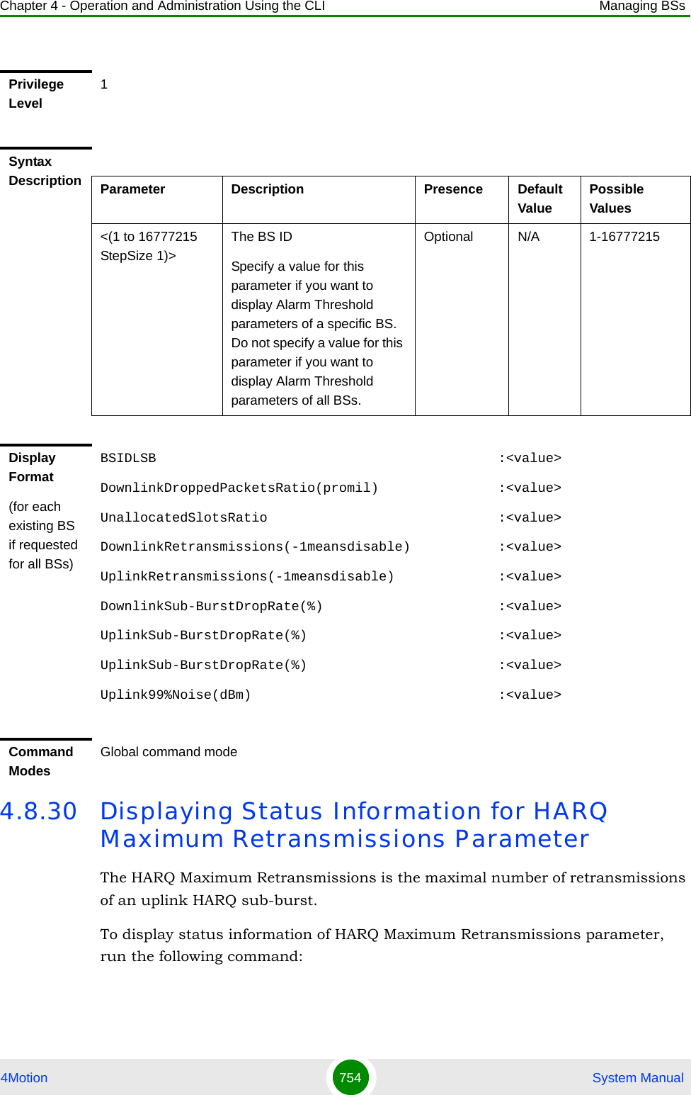
![Chapter 4 - Operation and Administration Using the CLI Managing BSs4Motion 750 System Manual4.8.29 Managing Alarm Threshold ParametersAfter enabling the BS configuration mode, you can execute the following tasks:Configure one or more of the Alarm Threshold parameters (refer to Section 4.8.29.1).Restore the default values of some or all of the Alarm Threshold parameters (refer to Section 4.8.29.2).You can display configuration and status information for the Alarm Threshold parameters of a selected or all existing BSs (refer to Section 4.8.29.3).4.8.29.1 Configuring Alarm Threshold ParametersFrom the BS configuration mode, run the following command:npu(config-bs-66053)# alrm-thrshld [dl-droppedpackets <(1 to 1000 StepSize 1)>] [unalloc-slots <(1 to 100 StepSize 1)>] [dl-retransmissions <(-1 to -1 StepSize 1) | (1 to 10 StepSize 0.1)>] [ul-retransmissions <(-1 to -1 StepSize 1) | (1 to 10 StepSize 0.1)>] [dl-subburstdrop <(0 to 100 StepSize 0.01)>] [ul-subburstdrop <(0 to 100 StepSize 0.01)>] [ul-mednoise <(-130 to 0 StepSize 1)>] [ul-99prcntnoise <(-130 to 0 StepSize 1)>]Syntax Description Parameter Description Presence Default ValuePossible Values<(1 to 16777215 StepSize 1)>The BS ID Specify a value for this parameter if you want to display all Ranging parameters of a specific BS. Do not specify a value for this parameter if you want to display all Ranging parameters of all BSs.Optional N/A 1-16777215Command ModesGlobal command modeTo configure the Alarm Threshold parameters:](https://usermanual.wiki/Alvarion-Technologies/BMAX-OR-25.Manual-4/User-Guide-1114032-Page-69.png)
![Chapter 4 - Operation and Administration Using the CLI Managing BSs4Motion 751 System ManualCommand Syntaxnpu(config-bs-66053)# alrm-thrshld [dl-droppedpackets <(1 to 1000 StepSize 1)> ] [unalloc-slots <(1 to 100 StepSize 1)> ] [dl-retransmissions <(-1 to -1 StepSize 1) | (1 to 10 StepSize 0.1)> ] [ul-retransmissions <(-1 to -1 StepSize 1) | (1 to 10 StepSize 0.1)> ] [dl-subburstdrop <(0 to 100 StepSize 0.01)> ] [ul-subburstdrop <(0 to 100 StepSize 0.01)> ] [ul-mednoise <(-130 to 0 StepSize 1)> ] [ul-99prcntnoise <(-130 to 0 StepSize 1)> ]Privilege Level10Syntax Description Parameter Description Presence Default Value Possible Valuesdl-droppedpackets <(1 to 1000 StepSize 1)>Downlink Dropped Packets Ratio. Threshold for excessive DL dropped packets ratio - all services alarm (in promils).Optional 1000 1 - 1000unalloc-slots <(1 to 100 StepSize 1)>Unallocated Slots Ratio. Alarm threshold for an excessive ratio of unallocated slots versus total number of slots (in percents), due to lack of space in map.Optional 100 1 - 100dl-retransmissions <(-1 to -1 StepSize 1) | (1 to 10 StepSize 0.1)>Downlink Retransmissions. Threshold for excessive downlink retransmissions (total transmissions/total transactions) alarm. A value of -1 means the alarm is disabled.Optional -1 -1 or 1 to 10 in steps of 0.1ul-retransmissions <(-1 to -1 StepSize 1) | (1 to 10 StepSize 0.1)>Uplink Retransmissions. Threshold for excessive uplink retransmissions (total transmissions/total transactions) alarm. A value of -1 means the alarm is disabled.Optional -1 -1 or 1 to 10 in steps of 0.1](https://usermanual.wiki/Alvarion-Technologies/BMAX-OR-25.Manual-4/User-Guide-1114032-Page-70.png)
![Chapter 4 - Operation and Administration Using the CLI Managing BSs4Motion 752 System Manual4.8.29.2 Restoring the Default Values of Alarm Threshold ParametesTo restore the default values of some or all of the Alarm Threshold parameters, run the following command:npu(config-bs-66053)# no alrm-thrshld [dl-droppedpackets] [unalloc-slots] [dl-retransmissions] [ul-retransmissions] [dl-subburstdrop] [ul-subburstdrop] [ul-mednoise] [ul-99prcntnoise]You can restore only some parameters to the default values by specifying only those parameter. For example, to restore only the dl-droppedpackets parameter to the default value, run the following command:npu(config-bs-66053)# no alrm-thrshld dl-droppedpacketsThis parameter will be restored to its default value, while the other parameters will remain unchanged.dl-subburstdrop <(0 to 100 StepSize 0.01)>Downlink Sub-Burst Drop Rate. Threshold for excessive downlink HARQ sub-burst drop rate alarm (in percents).Optional 100 0 to 100 in steps of 0.01ul-subburstdrop <(0 to 100 StepSize 0.01)>Uplink Sub-Burst Drop Rate. Threshold for excessive uplink HARQ sub-burst drop rate alarm (in percents).Optional 100 0 to 100 in steps of 0.01ul-mednoise <(-130 to 0 StepSize 1)>Uplink Median Noise. Threshold for excessive uplink median noise alarm (in dBm).Optional 0 -130 to 0ul-99prcntnoise <(-130 to 0 StepSize 1)>Uplink 99% Percentile Noise.Threshold for excessive UL 99% percentile noise alarm (in dBm).Optional 0 -130 to 0Command Modesbs configuration modeIMPORTANTWhen creating a new BS, at least one of the Alarm Threshold parameters must be configured explicitly (even if configured to the default value).](https://usermanual.wiki/Alvarion-Technologies/BMAX-OR-25.Manual-4/User-Guide-1114032-Page-71.png)
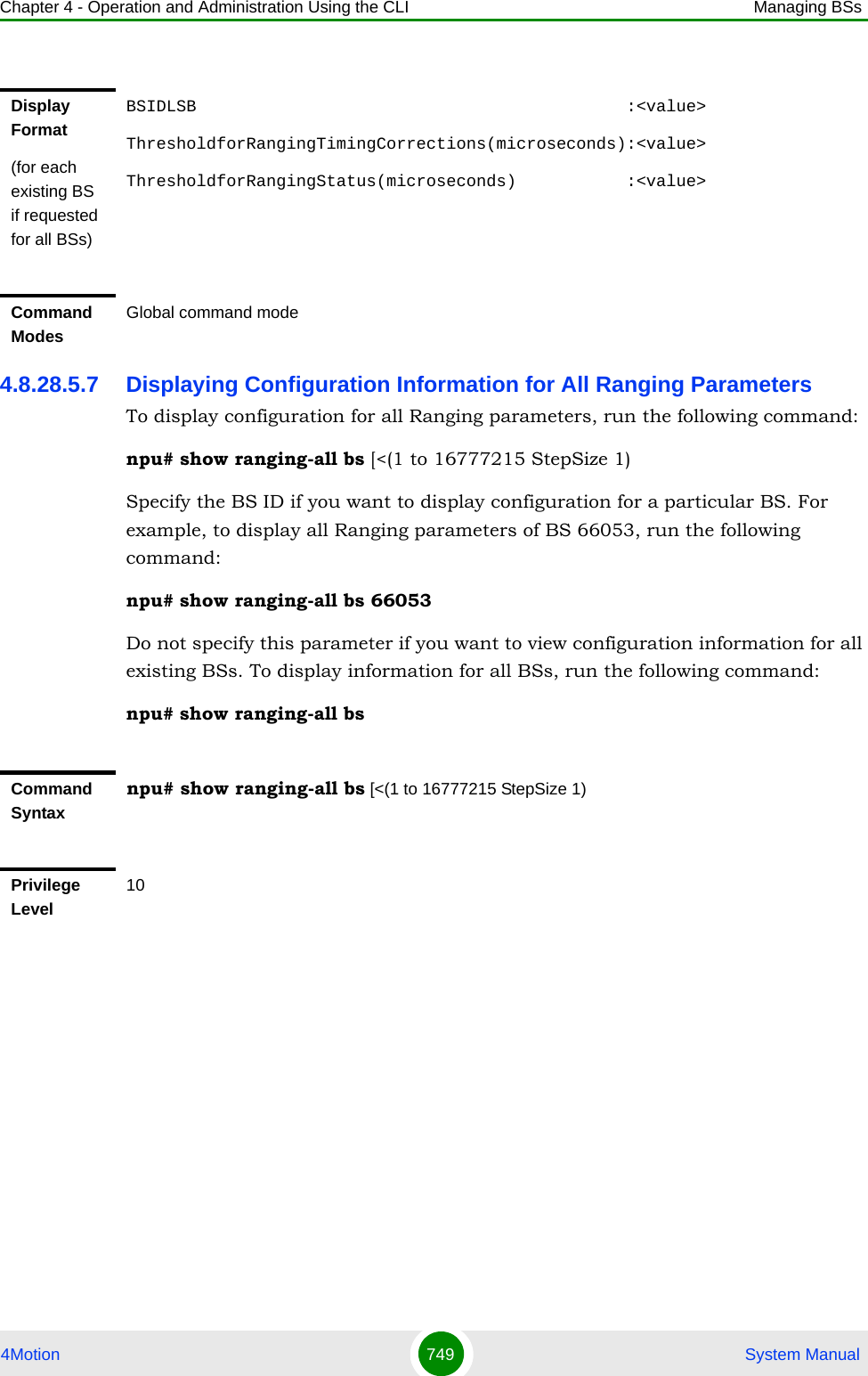
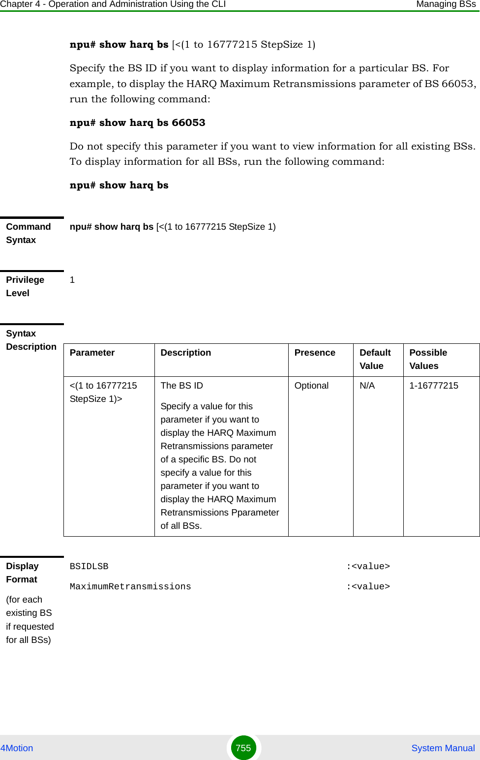
![Chapter 4 - Operation and Administration Using the CLI Managing BSs4Motion 753 System ManualTo restore all Alarm Threshold parameters to their default value, run the following command:npu(config-bs-66053)# no alrm-thrshld4.8.29.3 Displaying Configuration Information for Alarm Threshold ParametersTo display configuration information of Alarm Threshold parameters, run the following command:npu# show alrm-thrshld bs [<(1 to 16777215 StepSize 1)Specify the BS ID if you want to display information for a particular BS. For example, to display the Alarm Threshold parameters of BS 66053, run the following command:npu# show alrm-thrshld bs 66053Do not specify this parameter if you want to view information for all existing BSs. To display information for all BSs, run the following command:npu# show alrm-thrshld bsNOTERefer to Section 4.8.29.1 for a description and default values of these parameters.Command Syntaxnpu(config-bs-66053)# no alrm-thrshld [dl-droppedpackets ] [unalloc-slots ] [dl-retransmissions ] [ul-retransmissions ] [dl-subburstdrop ] [ul-subburstdrop ] [ul-mednoise ] [ul-99prcntnoise ]Privilege Level10Command Modesbs configuration modeCommand Syntaxnpu# show alrm-thrshld bs [<(1 to 16777215 StepSize 1)](https://usermanual.wiki/Alvarion-Technologies/BMAX-OR-25.Manual-4/User-Guide-1114032-Page-72.png)
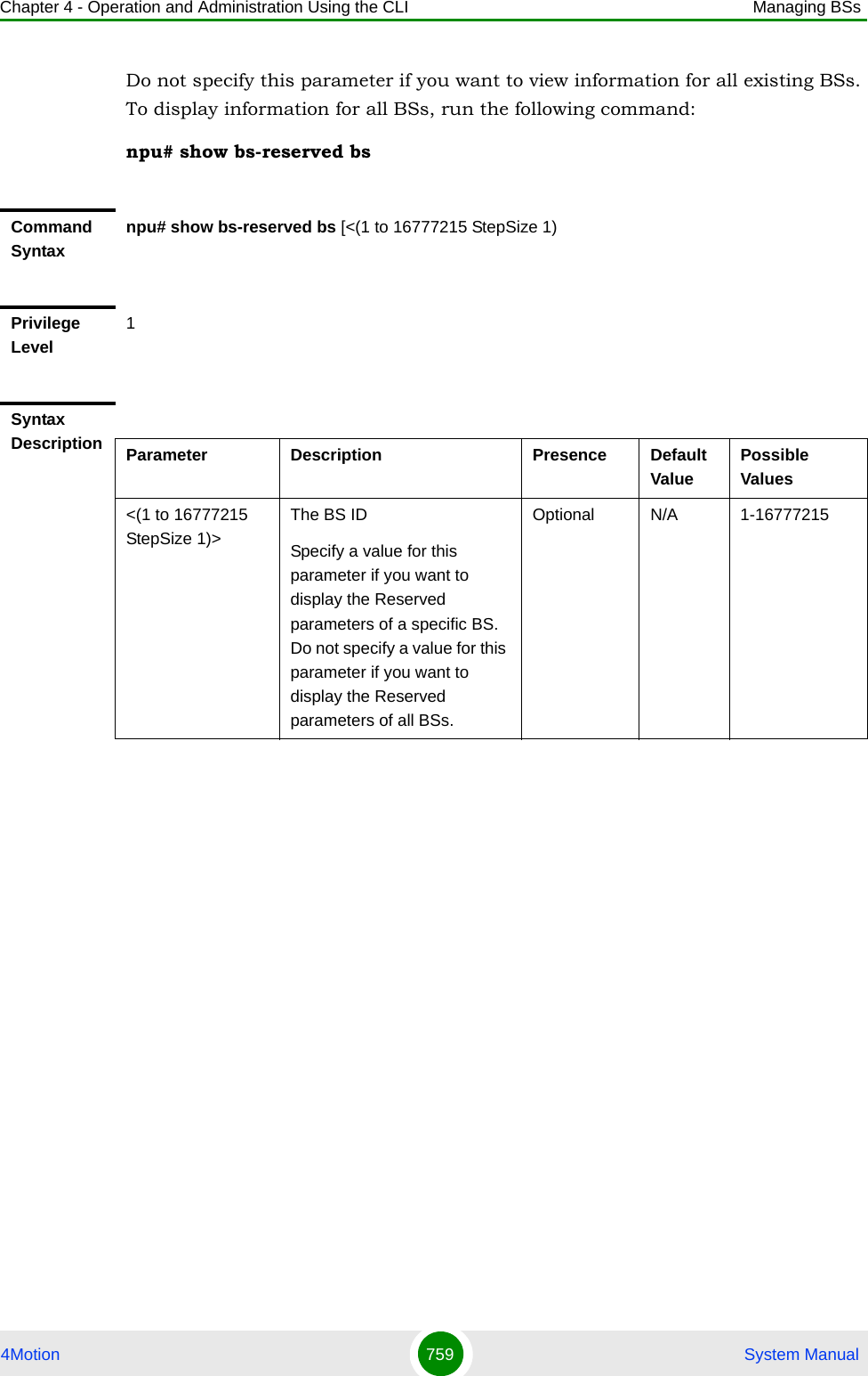
![Chapter 4 - Operation and Administration Using the CLI Managing BSs4Motion 756 System Manual4.8.31 Managing BS Reserved ParametersAfter enabling the BS configuration mode, you can execute the following tasks:Configure one or more of the BS Reserved parameters (refer to Section 4.8.31.1).Restore the default values of some or all of the BS Reserved parameters (refer to Section 4.8.31.2).You can display configuration information for the BS Reserved parameters of a selected or all existing BSs (refer to Section 4.8.31.3).4.8.31.1 Configuring BS Reserved ParametersAs the name implies, the reserved parameters table enables configuring up to 21 parameters that are reserved for possible future use. In the current release none of the reserved parameters is being used.To configure the BS reserved parameters, run the following command:npu(config-bs-66053-1)# bs-reserved [reserved-1 <string (32)> ] [reserved-2 <string (32)> ] [reserved-3 <string (32)> ] [reserved-4 <string (32)> ] [reserved-5 <string (32)> ] [reserved-6 <string (32)> ] [reserved-7 <string (32)> ] [reserved-8 <string (32)> ] [reserved-9 <string (32)> ] [reserved-10 <string (32)> ] [reserved-11 <string (32)> ] [reserved-12 <string (32)> ] [reserved-13 <string (32)> ] [reserved-14 <string (32)> ] [reserved-15 <string (32)> ] [reserved-16 <string (32)> ] [reserved-17 <string (32)> ] [reserved-18 <string (32)> ] [reserved-19 <string (32)> ] [reserved-20 <string (32)> ] [reserved-21 <string (32)> ]Command ModesGlobal command mode](https://usermanual.wiki/Alvarion-Technologies/BMAX-OR-25.Manual-4/User-Guide-1114032-Page-75.png)
![Chapter 4 - Operation and Administration Using the CLI Managing BSs4Motion 757 System Manual4.8.31.2 Restoring the Default Values of BS Reserved ParametesTo restore the default values of some or all of the BS Reserved parameters, run the following command:npu(config-bs-66053)# no bs-reserved [reserved-1] [reserved-2] [reserved-3] [reserved-4] [reserved-5] [reserved-6] [reserved-7] [reserved-8] [reserved-9] [reserved-10] [reserved-11] [reserved-12] [reserved-13] [reserved-14] [reserved-15] [reserved-16] [reserved-17] [reserved-18] [reserved-19] [reserved-20] [reserved-21]Command Syntaxnpu (config-bs-66053)# bs-reserved [reserved-1 <string (32)> ] [reserved-2 <string (32)> ] [reserved-3 <string (32)> ] [reserved-4 <string (32)> ] [reserved-5 <string (32)> ] [reserved-6 <string (32)> ] [reserved-7 <string (32)> ] [reserved-8 <string (32)> ] [reserved-9 <string (32)> ] [reserved-10 <string (32)> ] [reserved-11 <string (32)> ] [reserved-12 <string (32)> ] [reserved-13 <string (32)> ] [reserved-14 <string (32)> ] [reserved-15 <string (32)> ] [reserved-16 <string (32)> ] [reserved-17 <string (32)> ] [reserved-18 <string (32)> ] [reserved-19 <string (32)> ] [reserved-20 <string (32)> ] [reserved-21 <string (32)> ]Privilege Level10Syntax Description Parameter Description Presence Default Value Possible Values[reserved-N <string (32)>] (N=1-21)Reserved parameter number NOptional null (an empty string)A string of 32 printable characters.Command Modesbs configuration modeIMPORTANTWhen creating a new BS, at least one of the BS Reserved parameters must be configured explicitly (even if configured to the default value).](https://usermanual.wiki/Alvarion-Technologies/BMAX-OR-25.Manual-4/User-Guide-1114032-Page-76.png)
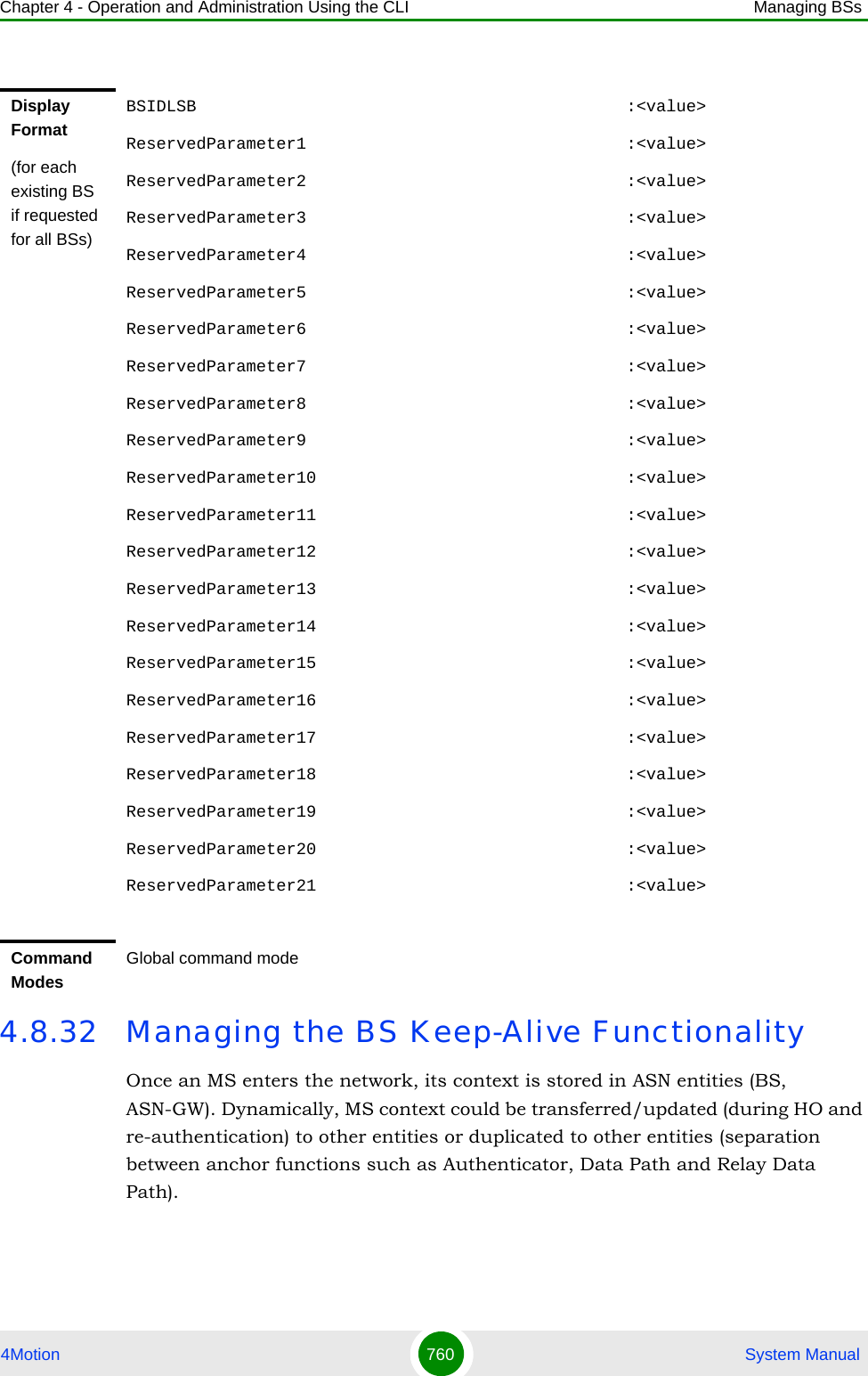
![Chapter 4 - Operation and Administration Using the CLI Managing BSs4Motion 758 System ManualYou can restore only some parameters to the default values by specifying only those parameter. For example, to restore only the reserved-1 and reserved-2 parameters to the default values, run the following command:npu(config-bs-66053)# no bs-reserved reserved-1 reserved-2These parameters will be restored to the default value, while the other parameters will remain unchanged.To restore all BS Reserved parameters to their default value, run the following command:npu(config-bs-66053)# no bs-reserved4.8.31.3 Displaying Configuration Information for BS Reserved ParametersTo display configuration information of BS Reserved parameters, run the following command:npu# show bs-reserved bs [<(1 to 16777215 StepSize 1)Specify the BS ID if you want to display information for a particular BS. For example, to display the BS Reserved parameters of BS 66053, run the following command:npu# show bs-reserved bs 66053NOTERefer to Section 4.8.31.1 for a description and default values of these parameters.Command Syntaxnpu(config-bs-66053)# no bs-reserved [reserved-1 ] [reserved-2 ] [reserved-3 ] [reserved-4 ] [reserved-5 ] [reserved-6 ] [reserved-7 ] [reserved-8 ] [reserved-9 ] [reserved-10 ] [reserved-11 ] [reserved-12 ] [reserved-13 ] [reserved-14 ] [reserved-15 ] [reserved-16 ] [reserved-17 ] [reserved-18 ] [reserved-19 ] [reserved-20 ] [reserved-21 ]Privilege Level10Command Modesbs configuration mode](https://usermanual.wiki/Alvarion-Technologies/BMAX-OR-25.Manual-4/User-Guide-1114032-Page-77.png)
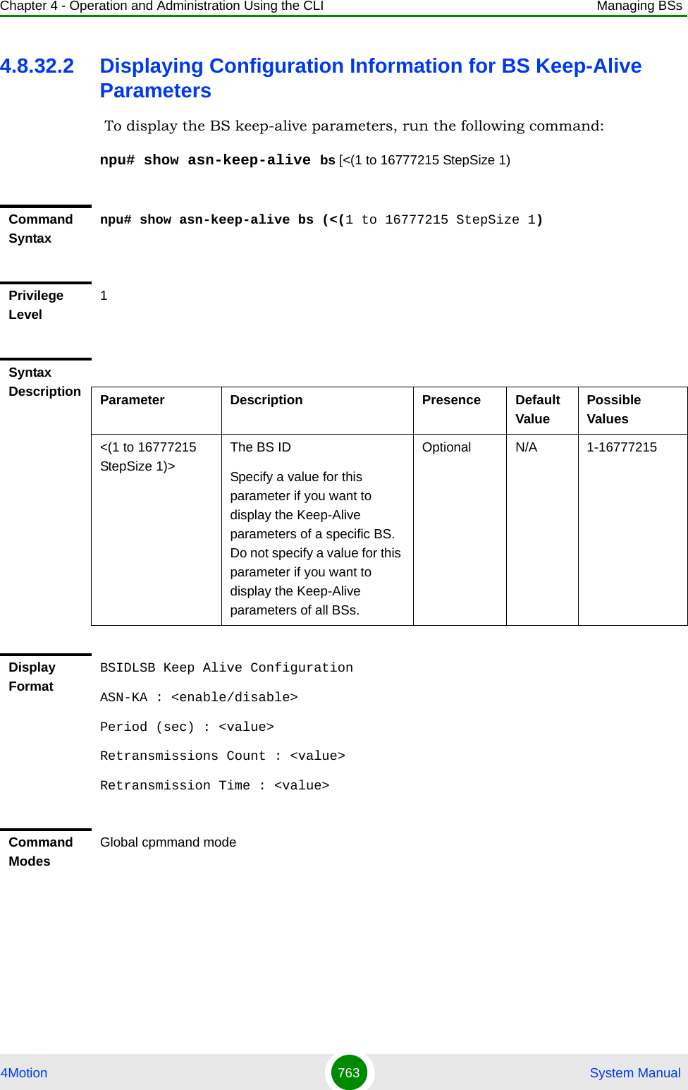
![Chapter 4 - Operation and Administration Using the CLI Managing BSs4Motion 762 System Manual4.8.32.1 Configuring BS Keep-Alive ParametersTo configure one or several keep-alive parameters, run the following command:npu(config-bs-66053)# asn-ka ([enable <enable|disable>]) [period <integer (10-1000)>] [rtx-cnt <integer (1-10)>] [rtx-time <integer (100-10000)>] Command Syntaxnpu(config-bs-66053)# asn-ka ([enable <enable|disable>]) [period <integer (10-1000)>] [rtx-cnt <integer (1-10)>] [rtx-time <integer (100-10000)>] Privilege Level10Syntax Description Parameter Description Presence Default ValuePossible Values[enable <enable|disable>]Enable/Disable the BS keep-alive mechanism.Optional disable enabledisable[period <integer (10-1000)>]The period ln seconds between polling sessions.period x 1000 (value in milliseconds) cannot be lower than (rtx-cnt ) x rtx-time+1).Optional 60 10-1000[rtx-cnt <integer (1-10)>]Maximum number of retries if rtx-time has expired without getting a response.Optional 3 1-10[rtx-timw <integer (100-10000)>]Time in milliseconds to wait for a response before initiating another polling attempt or reaching a decision that the polled entity has failed (if the maximum number of retries set by rtx-cnt has been reached).Optional 500 100-10000Command Modesbs configuration mode](https://usermanual.wiki/Alvarion-Technologies/BMAX-OR-25.Manual-4/User-Guide-1114032-Page-81.png)
![Chapter 4 - Operation and Administration Using the CLI Managing Sectors4Motion 765 System ManualTo create a new Sector object, the mandatory heading and width parameters must be specified. Run the following command to create a new Sector object and enable the parameters configuration mode for this ODU:npu (config)# sector-params <(1 to 6 StepSize 1)> [heading <(0 to 359 StepSize 1)> width <(0 to 359 StepSize 1)>]A new Sector object is created with default values for all parameters except to the mandatory heading and width parameters.For example, to create Sector 1 object and enable the parameters configuration mode for this Sector, where the heading is 180 and width is 90, run the following command:npu (config)# sector-params 1 heading 180 width 90After enabling the Sector Parameters configuration mode for a Sector you can execute any of the following tasks:Configure one or more of the parameters tables of the Sector (refer to Section 4.9.1.2)Restore the default values of non-mandatory parameters in one or more of the parameters tables of the Sector (refer to Section 4.9.1.3)After executing the above tasks, you can terminate the Sector Parameters configuration mode (refer to Section 4.9.1.4) and return to the global configuration mode.IMPORTANTAn error may occur if you provide an invalid value for any of these parameters. Refer the syntax description for more information about the appropriate values and format for configuring these parameters.Command Syntaxnpu (config)# sector-params <(1 to 6 StepSize 1)> [heading <(0 to 359 StepSize 1)> width <(0 to 359 StepSize 1)> ]Privilege Level10](https://usermanual.wiki/Alvarion-Technologies/BMAX-OR-25.Manual-4/User-Guide-1114032-Page-84.png)
![Chapter 4 - Operation and Administration Using the CLI Managing Sectors4Motion 766 System Manual4.9.1.2 Configuring Sector ParametersAfter enabling the Sector Parameters configuration mode you can configure the following parameters tables:Sector Definition (refer to Section 4.9.1.2.1)Sector Reserved (refer to Section 4.9.1.2.2)4.9.1.2.1 Configuring Sector Definition ParametersThe Sector Definition table enables configuring the main properties of the Sector.To configure the Sector Definition parameters, run the following command:npu(config-sector-params-1)# sector-definition [sector-name <string (32)>] [heading <(0 to 359 StepSize 1)>] [width <(0 to 359 StepSize 1)>]Syntax Description Parameter Description Presence Default Value Possible Values<(1 to 6 StepSize 1)> The Sector ID Mandatory N/A 1-6heading <(0 to 359 StepSize 1)>The sector heading (The center angle of the sector), in degrees.Mandatory when creating a new SectorN/A 0 - 359width <(0 to 359 StepSize 1)>The planned sector coverage, in degrees.Mandatory when creating a new SectorN/A 0 - 359Command ModesGlobal configuration modeNOTEThe following examples are for sector-1 parameters configuration mode.IMPORTANTAn error may occur if you provide an invalid value for any of these parameters. Refer the syntax description for more information about the appropriate values and format for configuring these parameters.](https://usermanual.wiki/Alvarion-Technologies/BMAX-OR-25.Manual-4/User-Guide-1114032-Page-85.png)
![Chapter 4 - Operation and Administration Using the CLI Managing Sectors4Motion 767 System Manual4.9.1.2.2 Configuring Sector Reserved ParametersAs the name implies, the reserved parameters table enables configuring up to 4 parameters that are reserved for possible future use. In the current release none of the reserved parameters is being used.To configure the Sector Reserved parameters, run the following command:npu(config-sector-params-1)# sector-reserved [reserved-1 <string (32)>] [reserved-2 <string (32)>] [reserved-3 <string (32)>] [reserved-4 <string (32)>].Command Syntaxnpu(config-sector-params-1)# sector-definition [sector-name <string (32)> ] [heading <(0 to 359 StepSize 1)> ] [width <(0 to 359 StepSize 1)> ]Privilege Level10Syntax Description Parameter Description Presence Default Value Possible Valuessector-name <string (32)>The sector name (description). Must be unique in the site (shelf).Optional null (empty string)A string of up to 32 charactersheading <(0 to 359 StepSize 1)>The sector heading (The center angle of the sector), in degrees.The heading of an associated Sector cannot be changed.Optional Configured previously0 - 359width <(0 to 359 StepSize 1)>The planned sector coverage, in degrees.Optional Configured previously0 - 359Command Modessector-params configuration modeCommand Syntaxnpu (config-sector-params-1)# sector-reserved [reserved-1 <string (32)>] [reserved-2 <string (32)>] [reserved-3 <string (32)>] [reserved-4 <string (32)>]](https://usermanual.wiki/Alvarion-Technologies/BMAX-OR-25.Manual-4/User-Guide-1114032-Page-86.png)
![Chapter 4 - Operation and Administration Using the CLI Managing Sectors4Motion 768 System Manual4.9.1.3 Restoring Default Values for Sector Configuration ParametersAfter enabling the Sector Parameters configuration mode you can restore the default values for parameters in the following parameters tables:Sector Definition (refer to Section 4.9.1.3.1)Sector Reserved (refer to Section 4.9.1.3.2)4.9.1.3.1 Restoring the Default Values of Sector Definition ParametersTo restore the non-mandatory sector-name parameter to the default value, run the following command:npu(config-sector-params-1)# no sector-definition [sector-name]Since there is only one non-mandatory parameters, you can use any one of the following two commands to restore the sector-name to its default value: npu(config-sector-params-1)# no sector-definitionor:npu(config-sector-params-1)# no sector-definition sector-namePrivilege Level10Syntax Description Parameter Description Presence Default Value Possible Values[reserved-N <string (32)>] (N=1-4)Reserved parameter number N Optional null (an empty string)A string of 32 printable characters.Command Modessector-params configuration modeNOTERefer to Section 4.9.1.2.1 for a description and default values of this parameter.](https://usermanual.wiki/Alvarion-Technologies/BMAX-OR-25.Manual-4/User-Guide-1114032-Page-87.png)
![Chapter 4 - Operation and Administration Using the CLI Managing Sectors4Motion 769 System Manual4.9.1.3.2 Restoring the Default Values of Sector Reserved ParametersTo restore Sector Reserved parameters to their default value, run the following command:npu(config-sector-params-1)# no sector-reserved [reserved-1] [reserved-2] [reserved-3] [reserved-4]You can restore only selected parameters to their default value by specifying only those parameter. For example, to restore only the reserved-1 parameter to its default values, run the following command:npu(config-sector-params-1)# no sector-reserved reserved-1This parameter will be restored to the default value, while the other parameters will remain unchanged.To restore all parameters to their default value, run the following command:npu(config-sector-params-1)# no sector-reservedCommand Syntaxnpu(config-sector-params-1)# no sector-definition [sector-name]Privilege Level10Command Modessector-params configuration modeNOTERefer to Section 4.9.1.2.2 for a description and default values of these parameters.Command Syntaxnpu(config-sector-params-1)# no sector-reserved [reserved-1] [reserved-2] [reserved-3] [reserved-4]Privilege Level10Command Modessector-params configuration mode](https://usermanual.wiki/Alvarion-Technologies/BMAX-OR-25.Manual-4/User-Guide-1114032-Page-88.png)
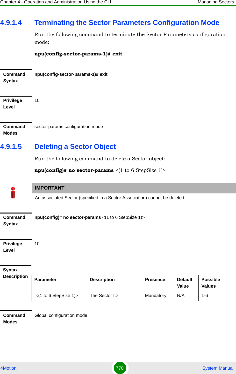
![Chapter 4 - Operation and Administration Using the CLI Managing Sectors4Motion 771 System Manual4.9.1.6 Displaying Configuration Information for Sector ParametersYou can display the current configuration and (where applicable) additional status information for the following parameters tables:Sector Definition (refer to Section 4.9.1.6.1)Sector Reserved (refer to Section 4.9.1.6.2)4.9.1.6.1 Displaying Configuration Information for Sector Definition ParametersTo display configuration information for the Sector Definition parameters of a specific or all Sector objects, run the following command:npu# show sector-definition [sector-id <(1 to 6 StepSize 1)>]Specify the Sector ID (1-6) if you want to display configuration information for a particular Sector. Do not specify a value for this parameter if you want to view configuration information for all existing Sector objects.Command Syntaxnpu# show sector-definition [sector-id <(1 to 6 StepSize 1)> ]Privilege Level1Syntax Description Parameter Description Presence Default ValuePossible Valuessector-id <(1 to 6 StepSize 1)> The Sector ID Specify a value for this parameter if you want to display the Sector Definition parameters of a specific Sector. Do not specify a value for this parameter if you want to display the parameters of all Sectors.Optional N/A 1-6](https://usermanual.wiki/Alvarion-Technologies/BMAX-OR-25.Manual-4/User-Guide-1114032-Page-90.png)
![Chapter 4 - Operation and Administration Using the CLI Managing Sectors4Motion 772 System Manual4.9.1.6.2 Displaying Configuration Information for Sector Reserved ParametersTo display configuration information for the reserved parameters of a specific or all Sector objects, run the following command:npu# show sector-reserved [sector-id <(1 to 6 StepSize 1)>]Specify the Sector ID (1-6) if you want to display configuration for a particular Sector. Do not specify a value for this parameter if you want to view configuration for all existing Sector objects.Display Format(for each existing ODU object if requested for all ODUs)SectorID :<value>SectorName :<value>SectorHeading(degrees) :<value>SectorWidth(degrees) :<value>Command ModesGlobal command modeCommand Syntaxnpu# show sector-reserved [sector-id <(1 to 6 StepSize 1)> ]Privilege Level1Syntax Description Parameter Description Presence Default ValuePossible Values<(1 to 6 StepSize 1)>The Sector ID.Specify a value for this parameter if you want to display the reserved parameters of a specific Sector. Do not specify a value for this parameter if you want to display the reserved parameters of all Sectors.Optional N/A 1-6](https://usermanual.wiki/Alvarion-Technologies/BMAX-OR-25.Manual-4/User-Guide-1114032-Page-91.png)
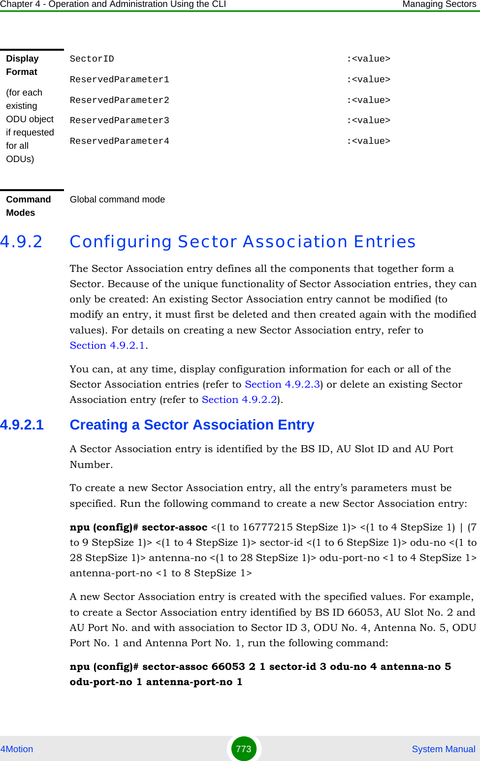
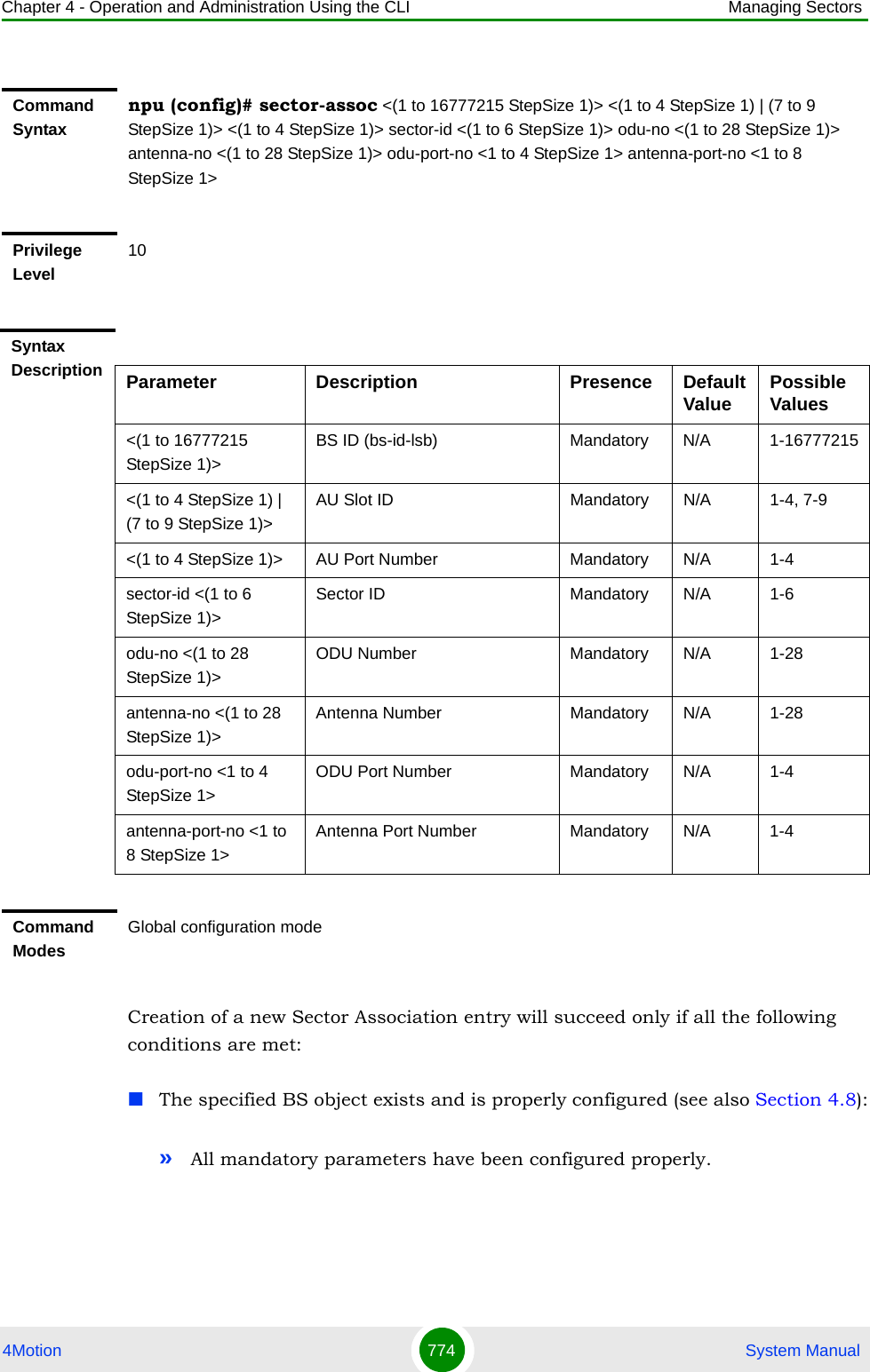
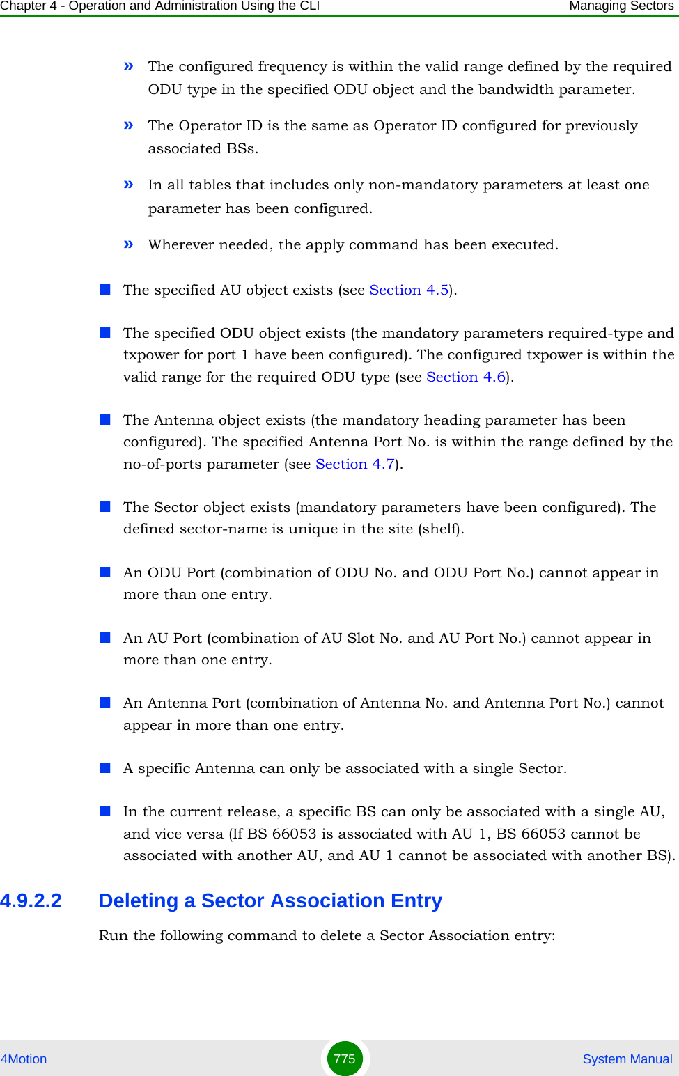
![Chapter 4 - Operation and Administration Using the CLI Managing Sectors4Motion 776 System Manualnpu (config)# no sector-assoc <(1 to 16777215 StepSize 1)> <(1 to 4 StepSize 1) | (7 to 9 StepSize 1)> <(1 to 4 StepSize 1)>Note that if all Sector Association entries with a particular BS are deleted (meaning the BS is no longer in use), this BS should be removed from all relevant Neighbour BS lists of other BSs.4.9.2.3 Displaying Configuration Information for Sector Association EntriesTo display configuration information of a specific or all Sector Association entries, run the following command:npu# show sector-assoc [bs-id-lsb <(1 to 16777215 StepSize 1)> au-slot-no <(1 to 4StepSize 1) | (7 to 9 StepSize 1)> au-port-no <(1 to 4 StepSize 1)>]Specify the BS ID (bs-id-lsb), AU Slot No. (au-slot-no) and AU Port number (au-port-no) if you want to display configuration information for a particular Sector Association entry. Do not specify values for these parameters if you want to view configuration information for all existing Sector Association entries.Command Syntaxnpu (config)# no sector-assoc <(1 to 16777215 StepSize 1)> <(1 to 4 StepSize 1) | (7 to 9 StepSize 1)> <(1 to 4 StepSize 1)>Privilege Level10Syntax Description Parameter Description Presence Default ValuePossible Values<(1 to 16777215 StepSize 1)>BS ID (bs-id-lsb) Mandatory N/A 1-16777215<(1 to 4 StepSize 1) | (7 to 9 StepSize 1)>AU Slot ID Mandatory N/A 1-4, 7-9<(1 to 4 StepSize 1)> AU Port Number Mandatory N/A 1-4Command ModesGlobal configuration mode](https://usermanual.wiki/Alvarion-Technologies/BMAX-OR-25.Manual-4/User-Guide-1114032-Page-95.png)
![Chapter 4 - Operation and Administration Using the CLI Managing Sectors4Motion 777 System ManualCommand Syntaxnpu# show sector-assoc [bs-id-lsb <(1 to 16777215 StepSize 1)> au-slot-no <(1 to 4StepSize 1) | (7 to 9 StepSize 1)> au-port-no <(1 to 4 StepSize 1)> ]Privilege Level1Syntax Description Parameter Description Presence Default ValuePossible Values<bs-id-lsb (1 to 16777215 StepSize 1)>BS IDSpecify only if you want to display configuration of a particular Sector Association entry.Optional N/A 1-16777215<(1 to 4 StepSize 1) | (7 to 9 StepSize 1)>AU Slot IDSpecify only if you want to display configuration of a particular Sector Association entry.Optional N/A 1-4, 7-9<(1 to 4 StepSize 1)>AU Port NumberSpecify only if you want to display configuration of a particular Sector Association entry.Optionaly N/A 1-4Display Format(for each existing ODU Port if requested for all ODU Ports)BSIDLSB :<value>AUSlotNo. :<value>AUPortNo. :<value>SectorID :<value>ODUNo. :<value>ODUPortNo. :<value>AntennaNo. :<value>AntennaPortNo. :<value>Command ModesGlobal command mode](https://usermanual.wiki/Alvarion-Technologies/BMAX-OR-25.Manual-4/User-Guide-1114032-Page-96.png)
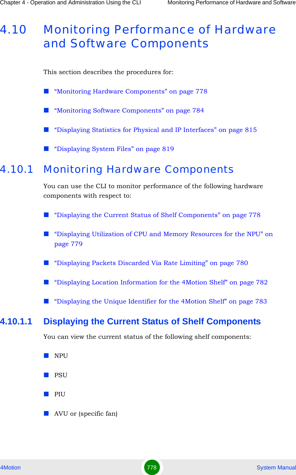
![Chapter 4 - Operation and Administration Using the CLI Monitoring Performance of Hardware and Software 4Motion 779 System ManualTo view the current status of all shelf components, run the following command:npu# show shelf status [{NPU [<slot id>] | PSU [<slot id (1-4)>] |PIU [<slot id (1-2)>] | AVU | Fan [<fan_num (1-10)>]}]For example, run the following command to view the status of the PSU, slot# 4:npu# show shelf status PSU 4To view the status of all the shelf components, run the following command:npu# show shelf status4.10.1.2 Displaying Utilization of CPU and Memory Resources for the NPUTo display the utilization of CPU and memory resources for the NPU, run the following command:npu# show resource usageAfter you run this command, the current CPU and memory usage is displayed.NOTERefer Figure 4-1 for more information about the slot IDs assigned to each shelf component.Command Syntaxnpu# show shelf status [{NPU [<slot id>] | PSU [<slot id (1-4)>] |PIU [<slot id (1-2)>] | AVU | Fan [<fan_num (1-10)>]}]Privilege Level1Syntax Description Parameter Description Presence Default ValuePossible Values[{NPU [<slot id>] | PSU [<slot id (1-4)>] |PIU [<slot id (1-2)>] | AVU | Fan [<fan_num (1-10)>]}Indicates the shelf components for which you want to display the current status. Do not specify any component to view the status of all components.Optional N/A NPUPSUPIUAVUFan<(1-10>](https://usermanual.wiki/Alvarion-Technologies/BMAX-OR-25.Manual-4/User-Guide-1114032-Page-98.png)
![Chapter 4 - Operation and Administration Using the CLI Monitoring Performance of Hardware and Software 4Motion 780 System Manual4.10.1.3 Displaying Packets Discarded Via Rate LimitingTo retrieve the number of packets discarded because of rate limiting for a specific or all applications (pre-defined, user-defined or all), run the following command:npu# show rate-limit counters {ftp | telnet | tftp | ssh | icmp | snmp | R4-R6 | igmp | eap | arp | all-others | <user-defined-app> | all}NOTEFor more information about setting thresholds for CPU and memory usage, refer to “Displaying CPU and Memory Utilization Limits for the NPU” on page 183.Command Syntaxnpu# show resource usagePrivilege Level1Display FormatResource Usage[in %]CPU <value>Memory 7<value>Command ModesGlobal command modeNOTEFor more information about configuring rate limiting, refer to “Configuring the Rate Limiting for the NPU” on page 184.Command Syntaxnpu# show rate-limit counters {ftp | telnet | tftp | ssh | icmp | snmp | R4-R6 | igmp | eap | arp | all-others | <user-defined-app> | all}Privilege Level1](https://usermanual.wiki/Alvarion-Technologies/BMAX-OR-25.Manual-4/User-Guide-1114032-Page-99.png)
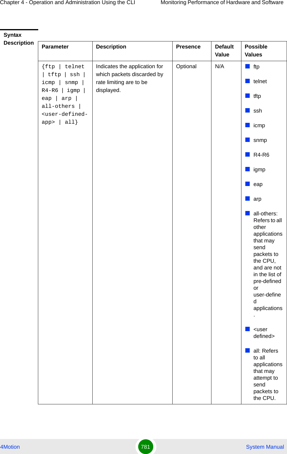
![Chapter 4 - Operation and Administration Using the CLI Monitoring Performance of Hardware and Software 4Motion 782 System Manual4.10.1.4 Displaying Location Information for the 4Motion ShelfTo display location information for the shelf, run the following command:npu# show site [{Name |Address | RackLocation | ContactPerson | AsnName |Region | ProductType |ShelfHwVersion}]Specify the shelf parameter for which you want to view the related details. For example, if you want to display information about the rack location, run the following command:npu# show site RackLocationIf you want to view information about for all shelf parameters, run the following command:npu# show siteDisplay FormatRATELIMIT COUNTERS: Pre-defined applications--------------------------------------------Application Packets discarded <Application> <Number of Packets Discarded> <Application> <Number of Packets Discarded> SSH<Application> <Number of Packets Discarded> SNMPRATELIMIT COUNTERS: User-defined applications---------------------------------------------Application Packets discarded<Application> <Number of Packets Discarded>Command ModesGlobal command modeCommand Syntaxnpu# show site [{Name |Address | RackLocation | ContactPerson | AsnName |Region | ProductType |ShelfHwVersion}]Privilege Level1](https://usermanual.wiki/Alvarion-Technologies/BMAX-OR-25.Manual-4/User-Guide-1114032-Page-101.png)
![Chapter 4 - Operation and Administration Using the CLI Monitoring Performance of Hardware and Software 4Motion 783 System Manual4.10.1.5 Displaying the Unique Identifier for the 4Motion ShelfTo display the unique identifier assigned to the 4Motion shelf, run the following command:npu# show site identifierSyntax Description Parameter Description Presence Default ValuePossible Values[{Name |Address | RackLocation | ContactPerson |AsnName |Region | ProductType |ShelfHwVersion}]Indicates the shelf parameter for which informationis to be displayed. If you do not enter any value for this parameter, information for all the shelf parameters is displayed.Optional N/A NameAddressRackLocationContactPersonAsnNameRegionProductTypeShelfHwVersionDisplay FormatSite:Name : <Name>Address : <Address>Rack Location : <Location>Contact Person : <Name>ASN Name : <value>Region : <value> Product Type : <value>Shelf HW Version : <value>Command ModesGlobal command mode](https://usermanual.wiki/Alvarion-Technologies/BMAX-OR-25.Manual-4/User-Guide-1114032-Page-102.png)
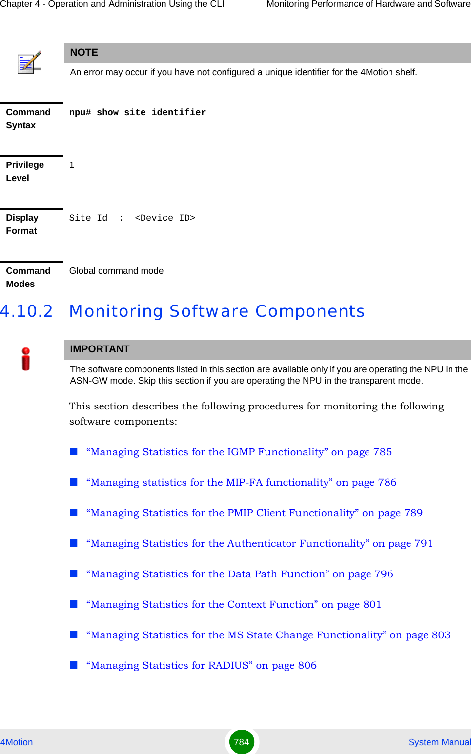
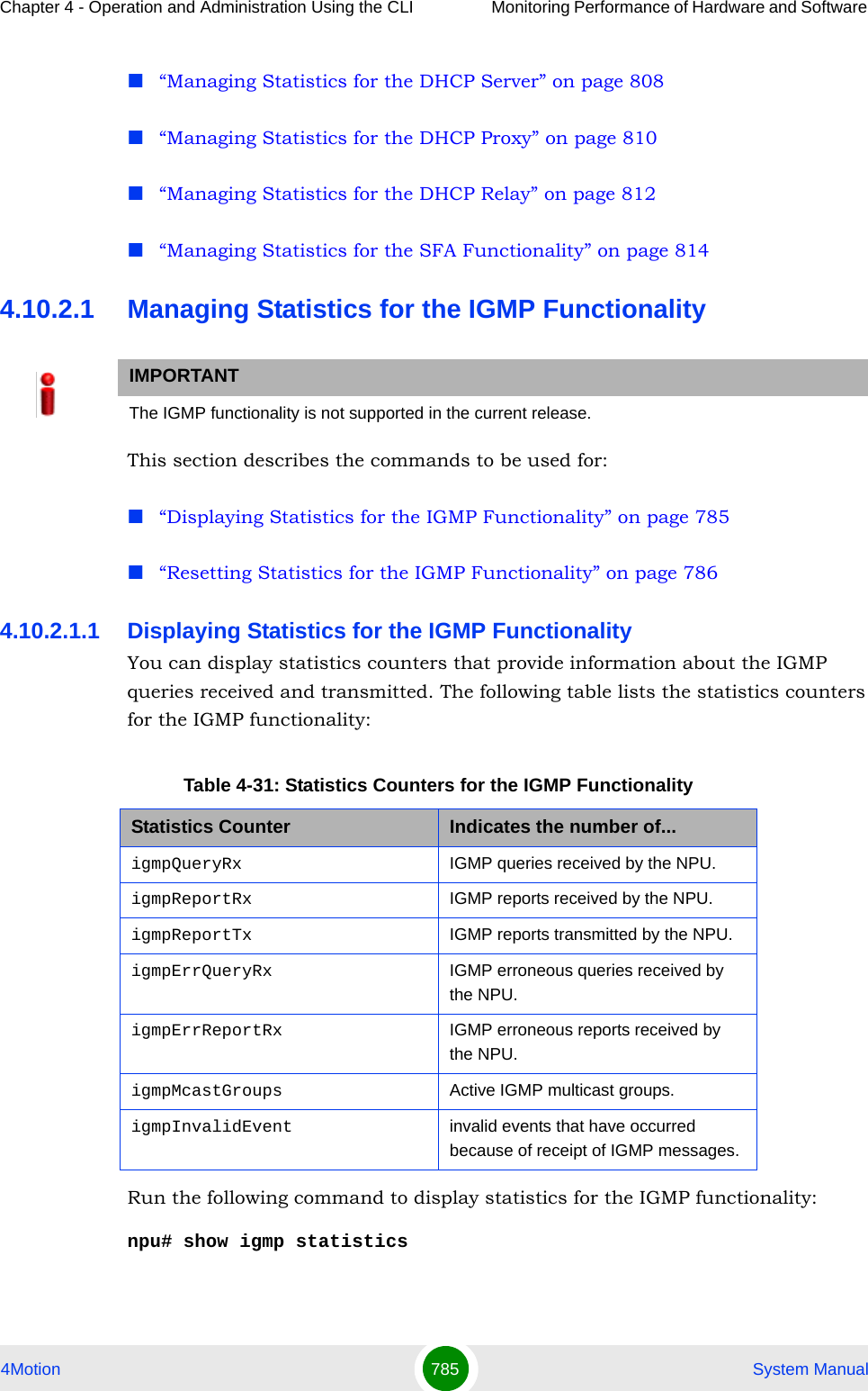
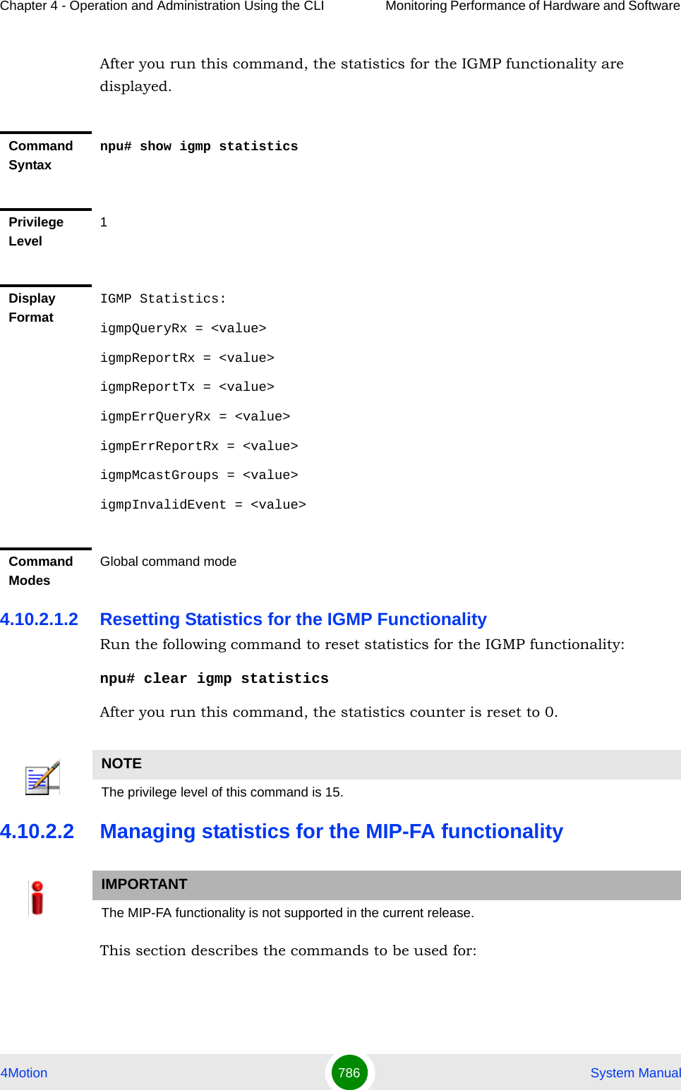
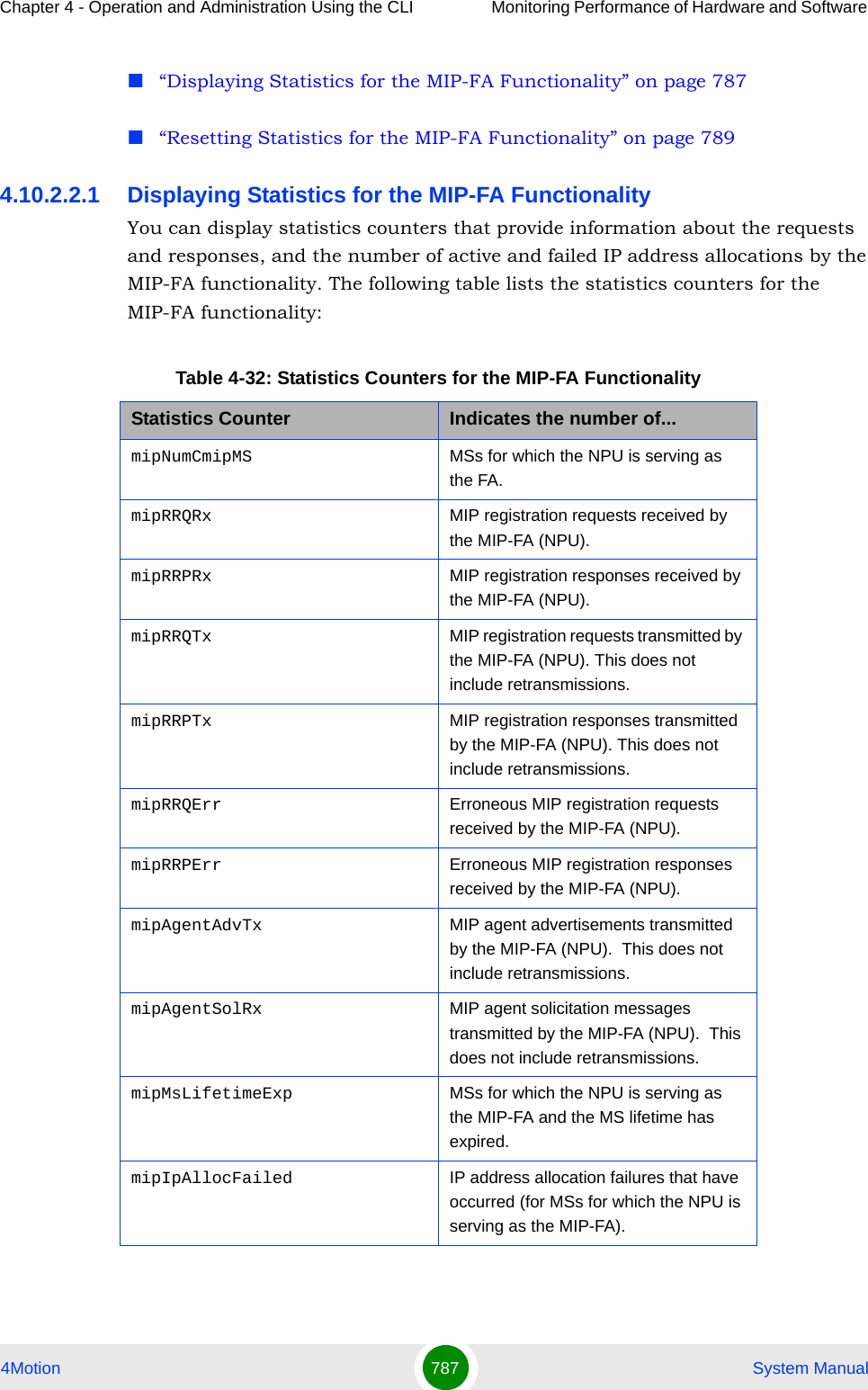
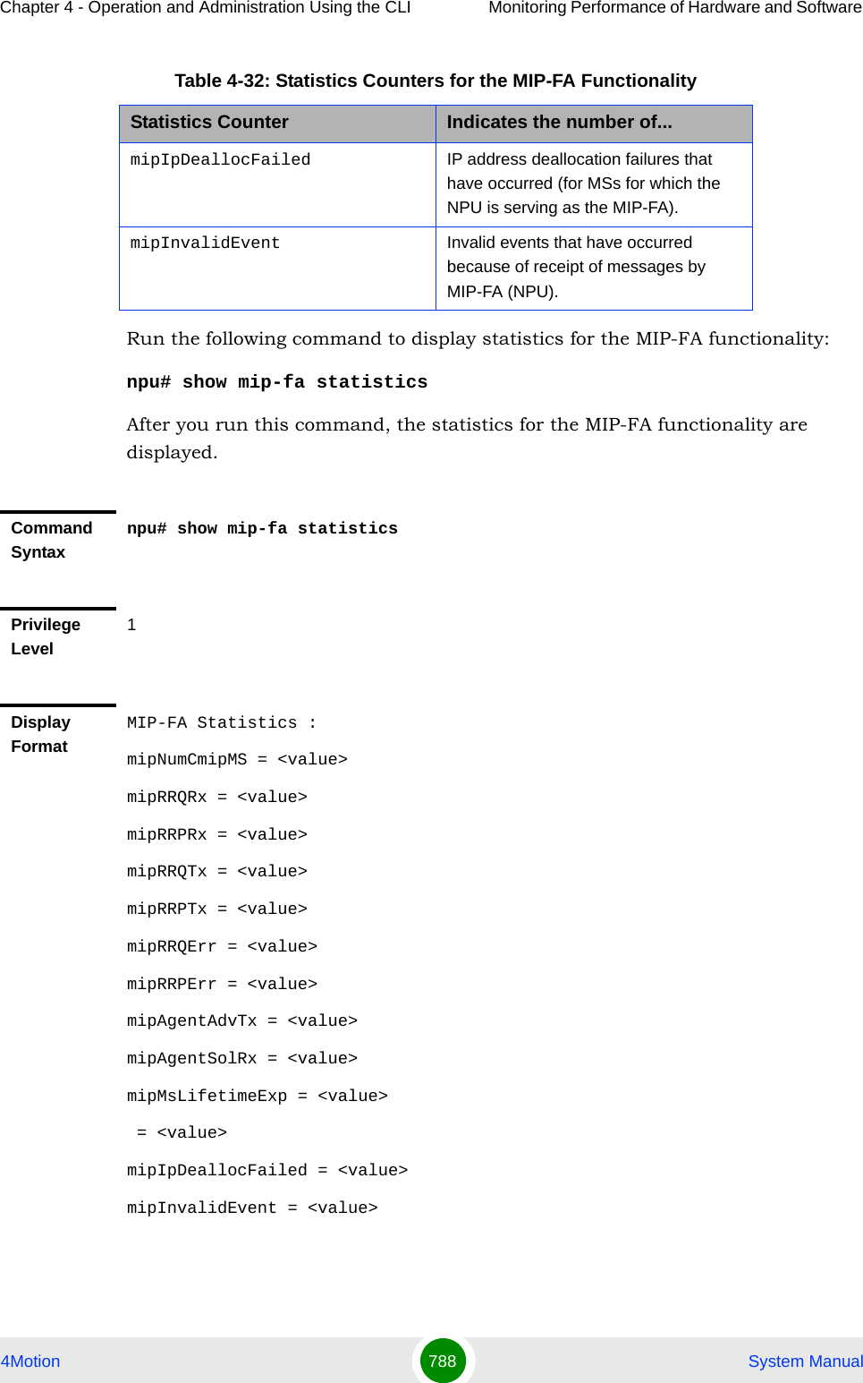
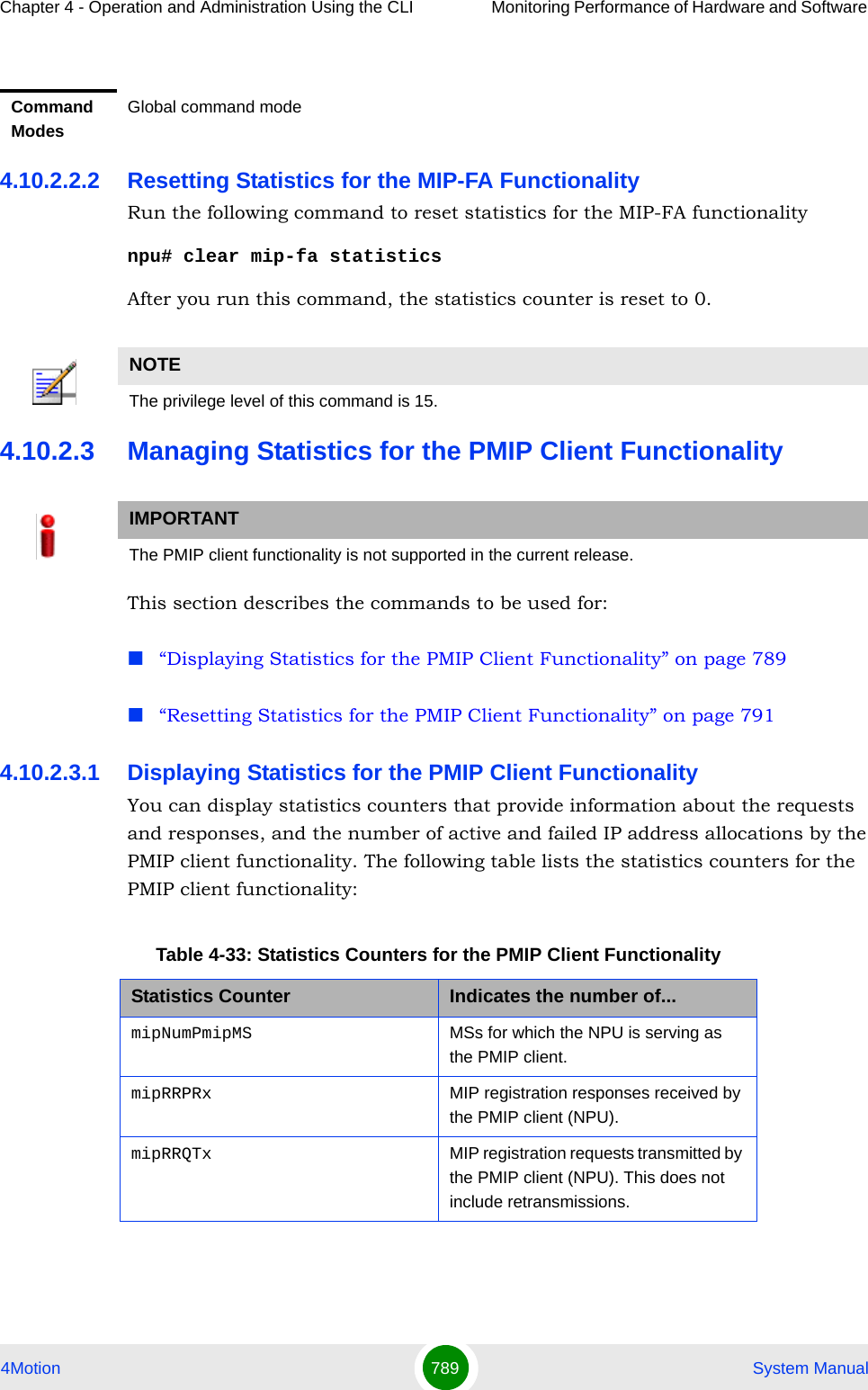
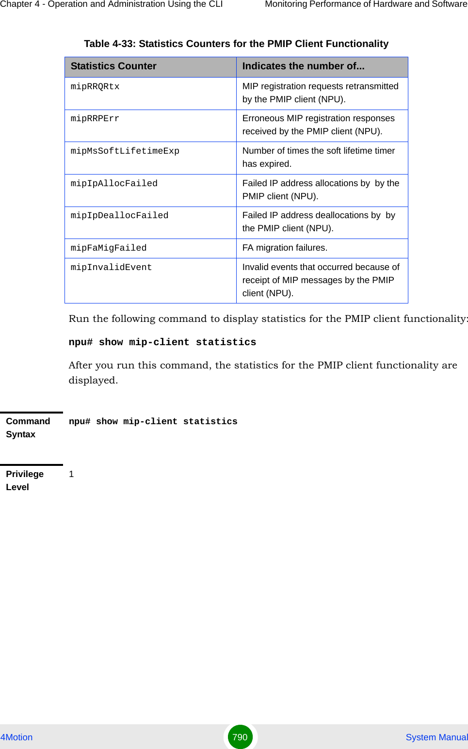
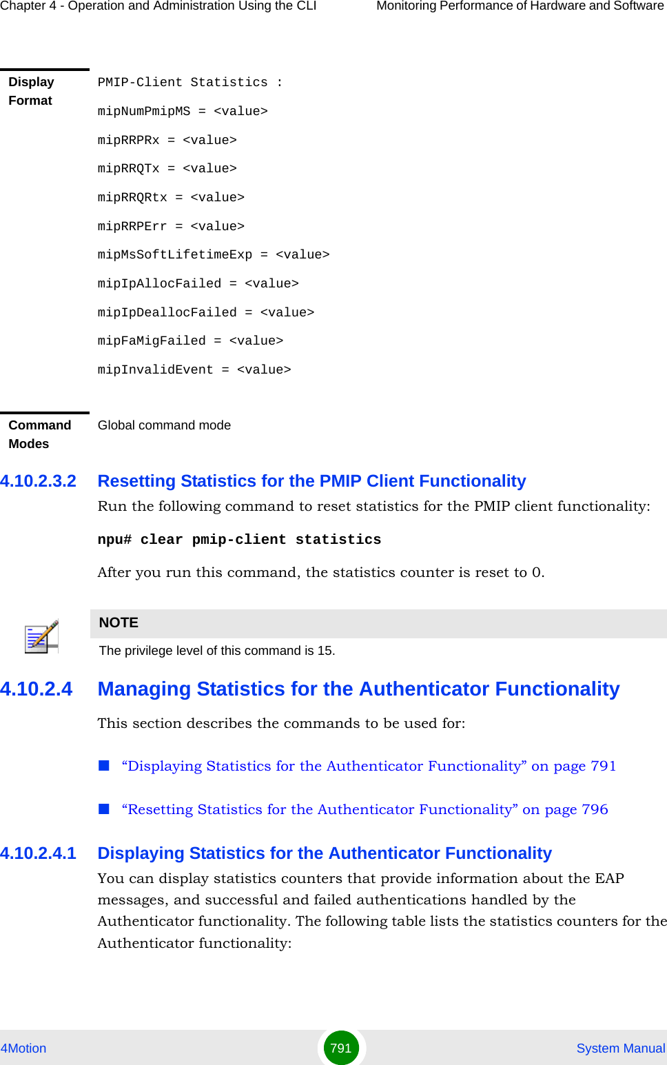
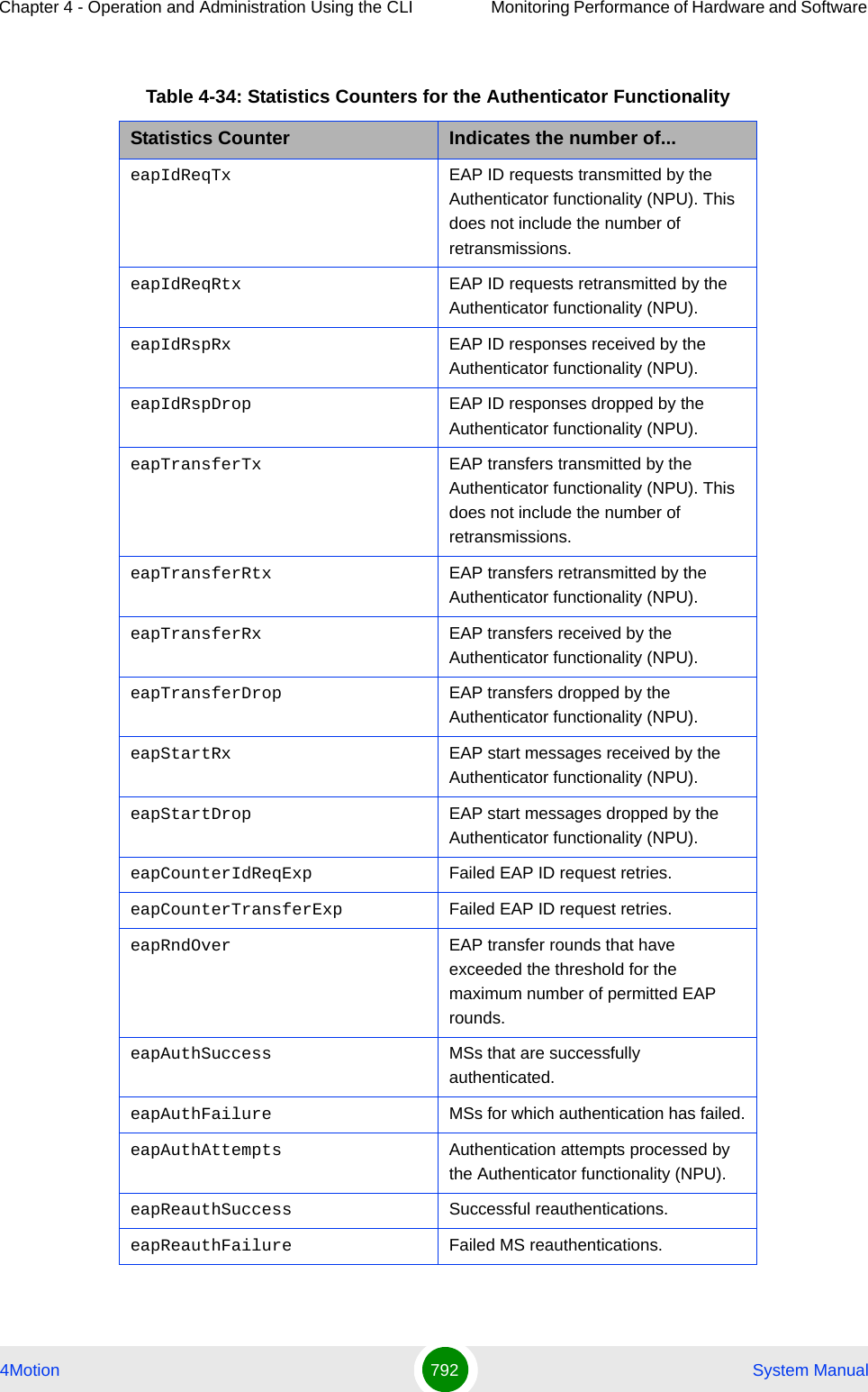
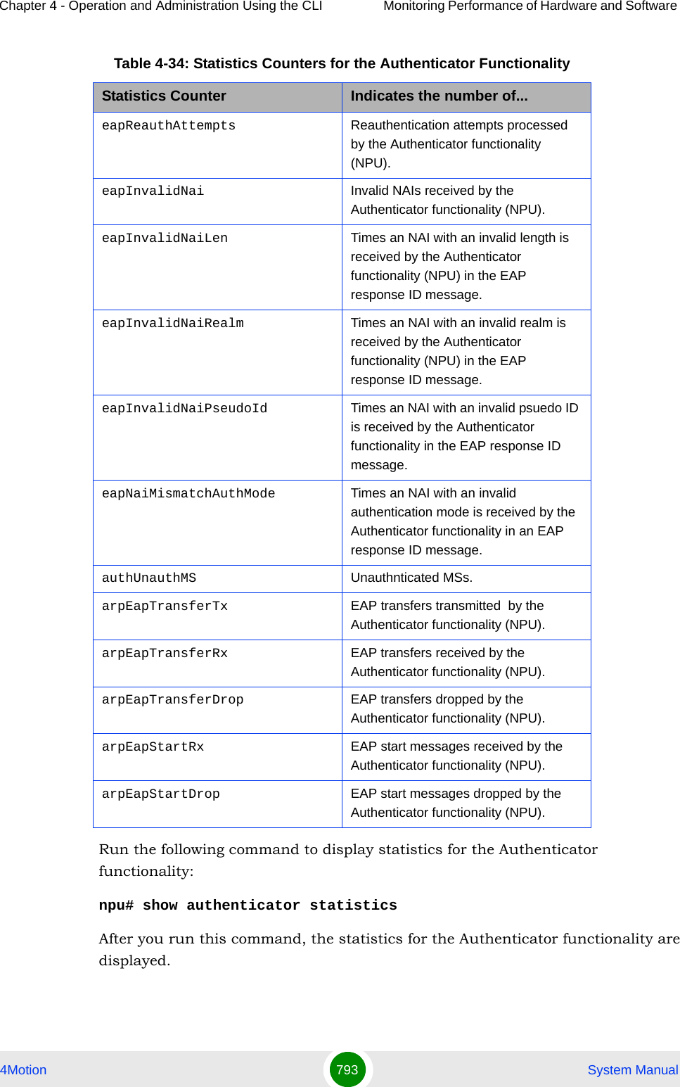
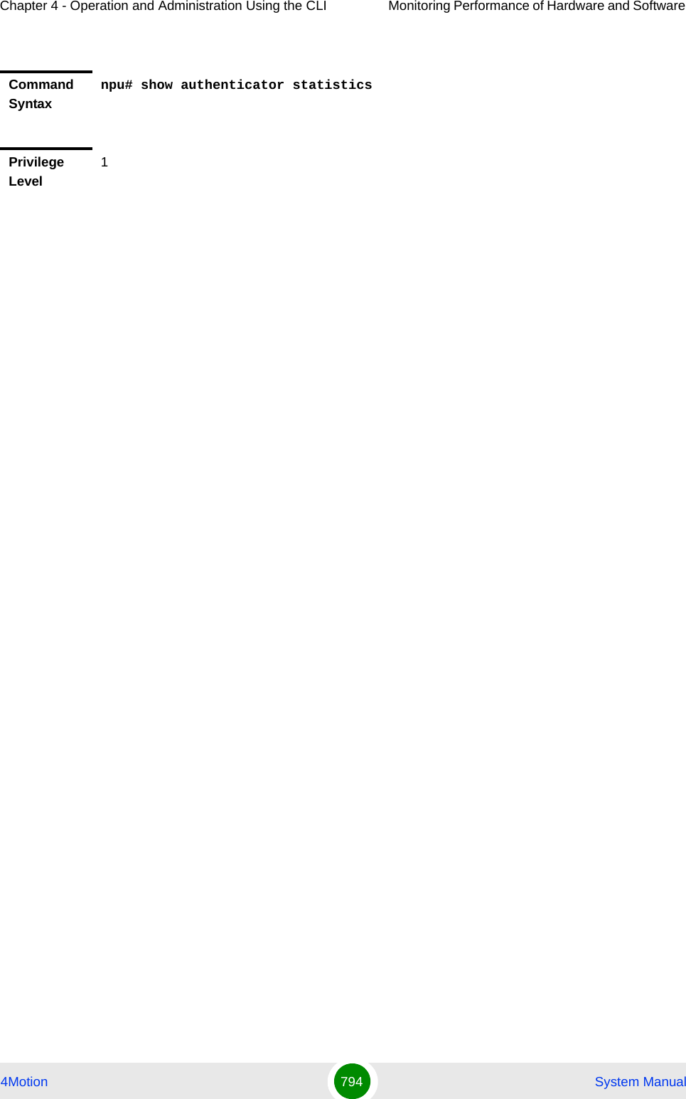
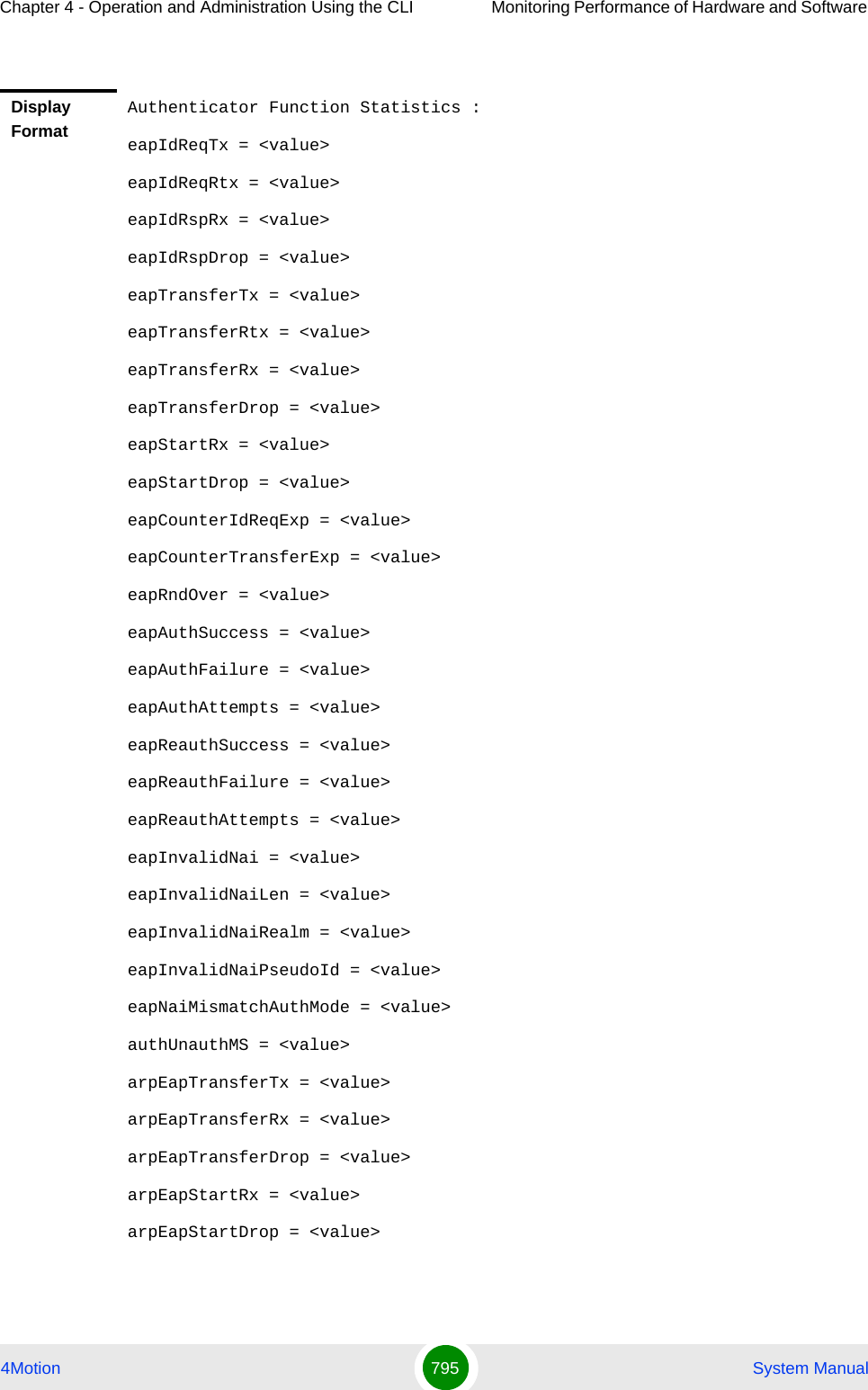
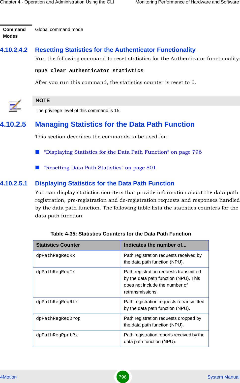
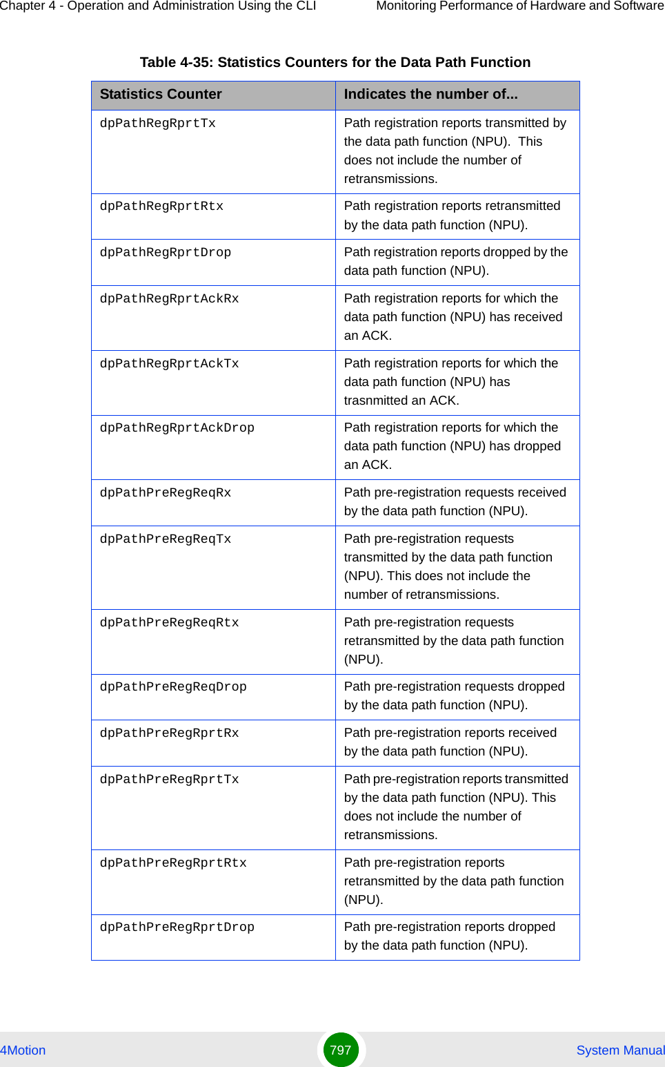
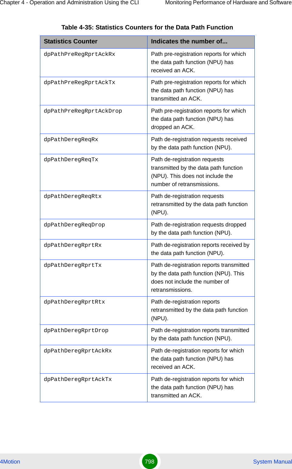
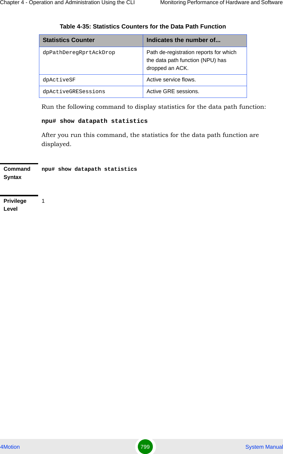
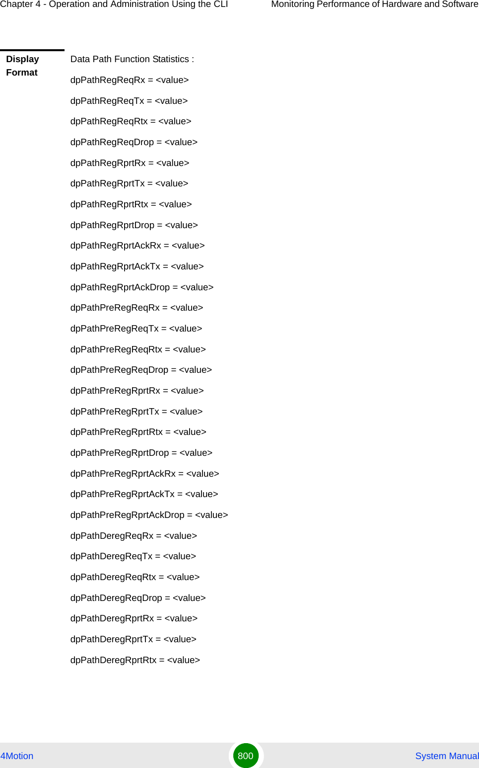
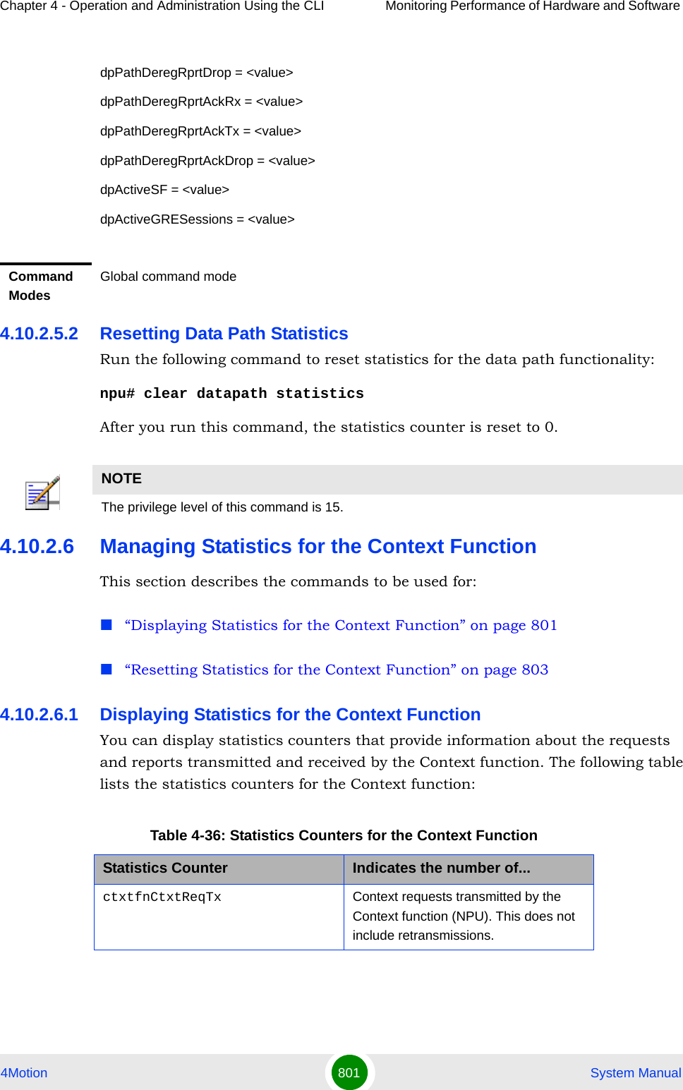
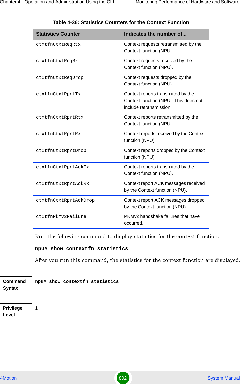
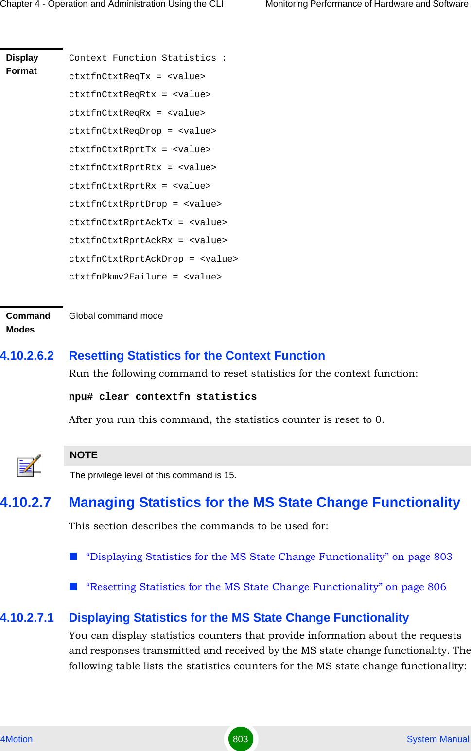
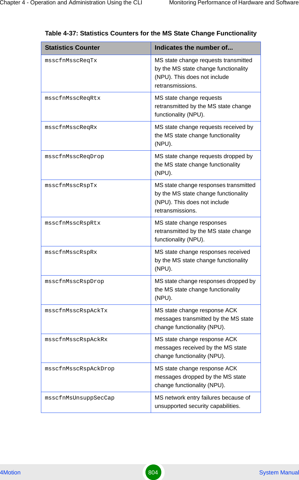
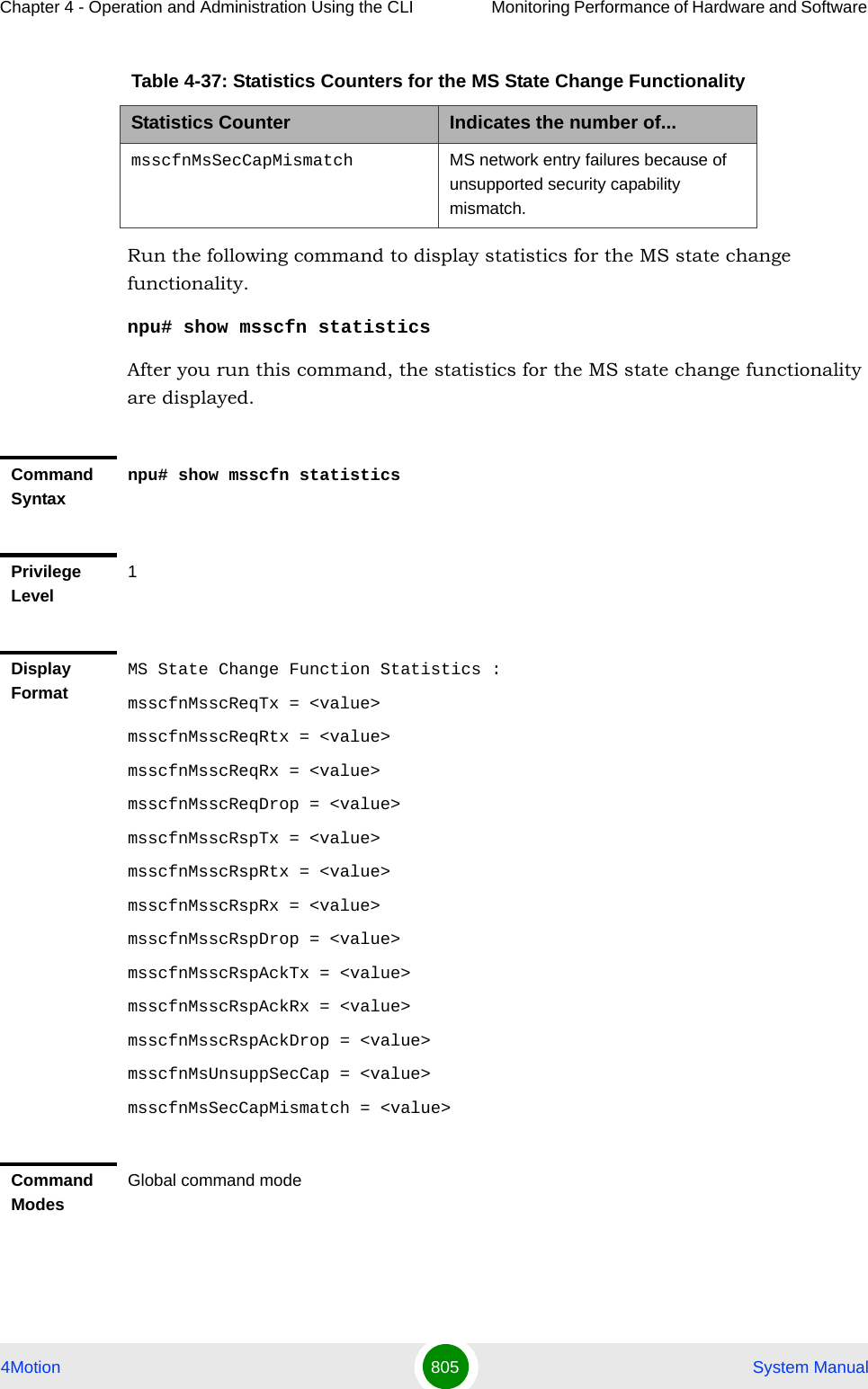
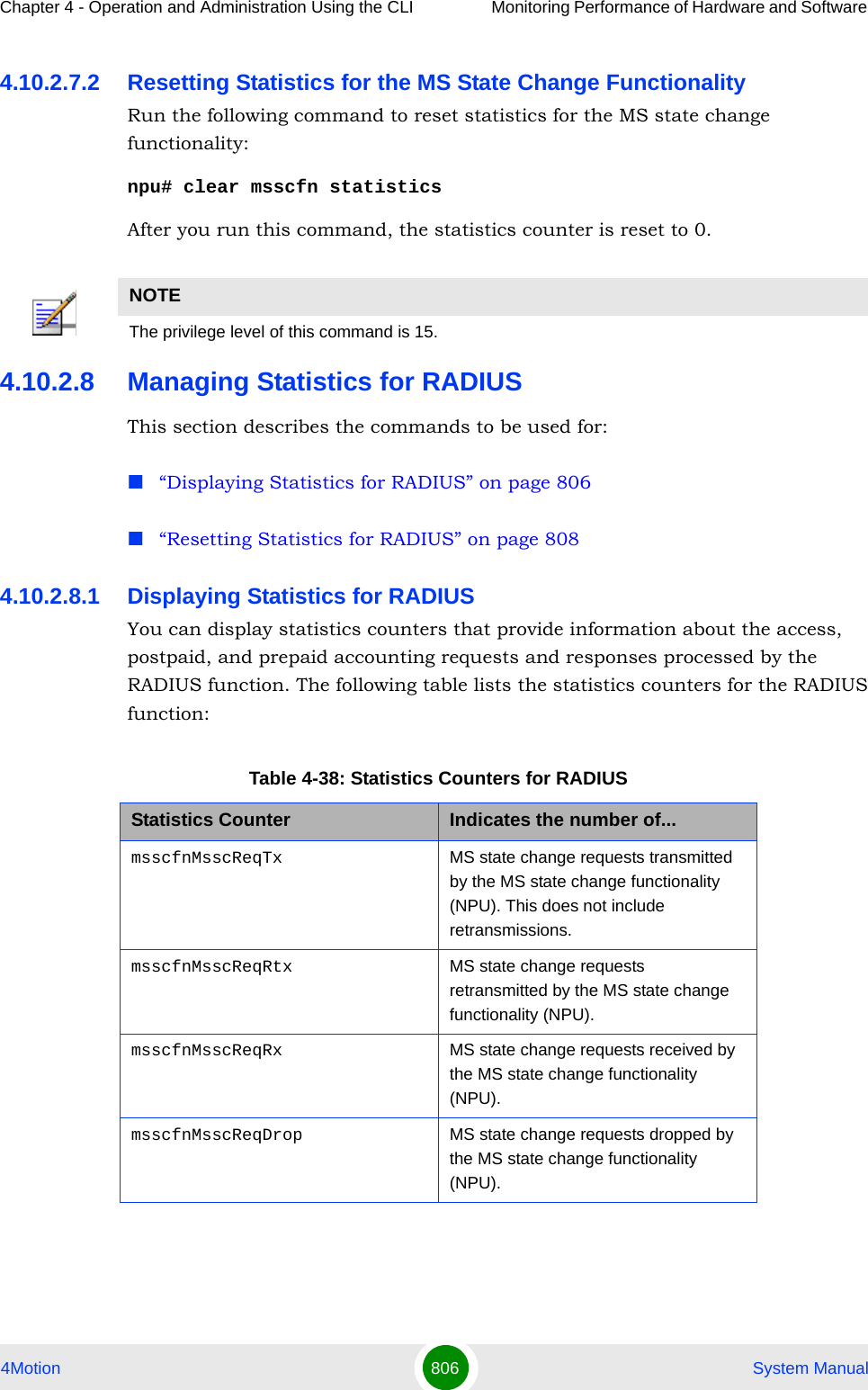
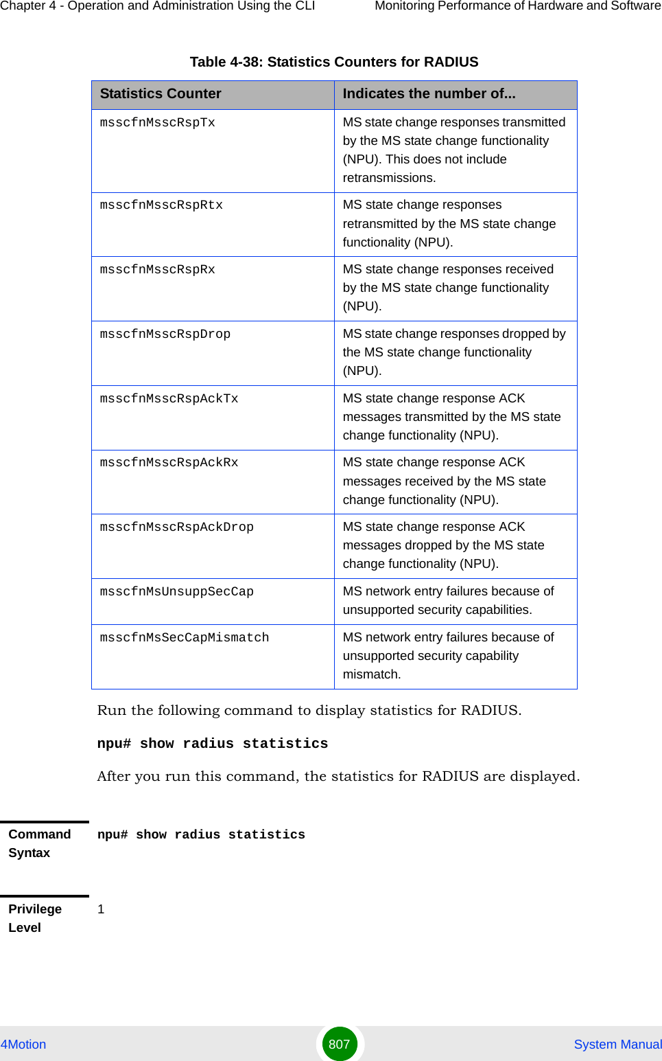
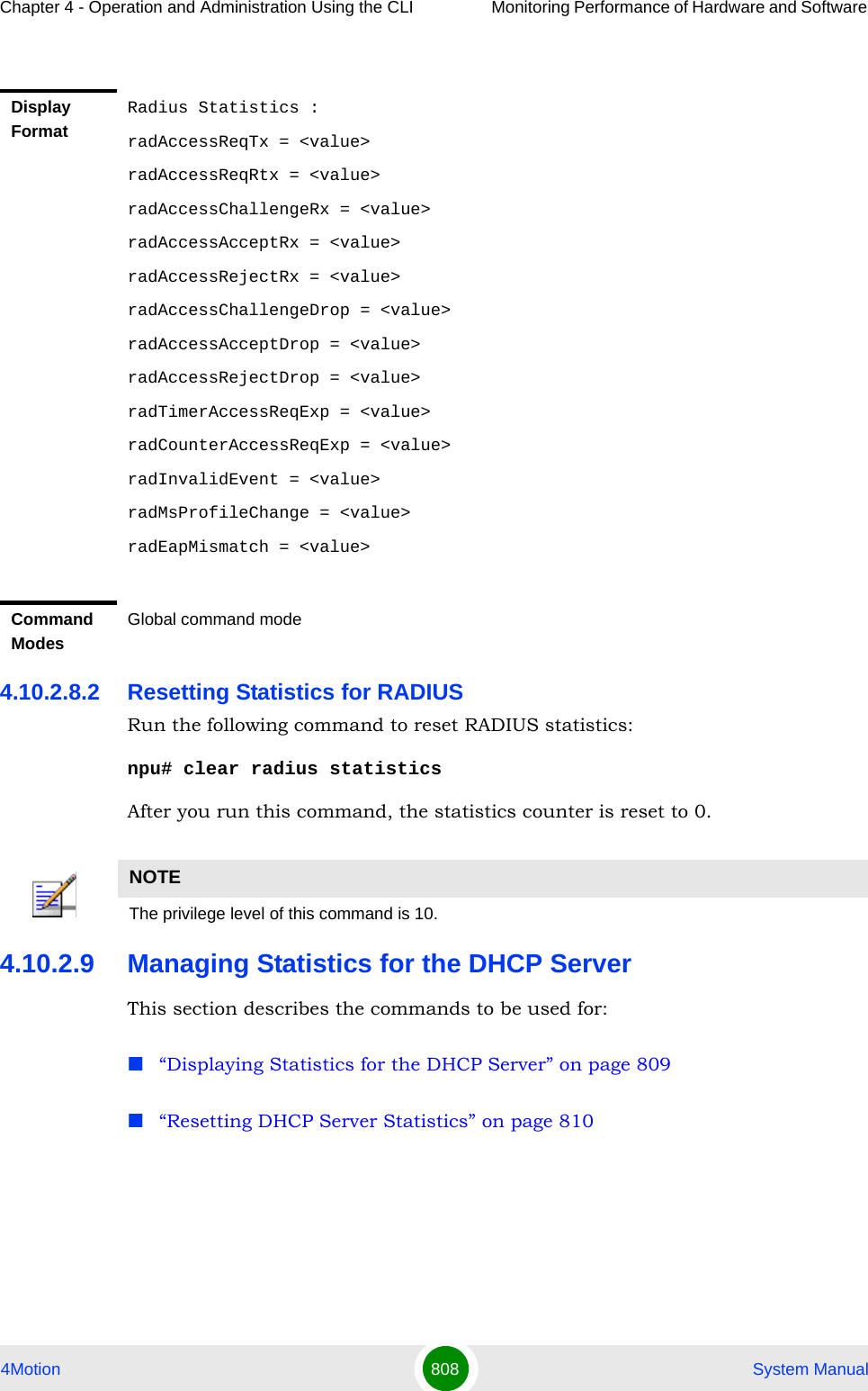
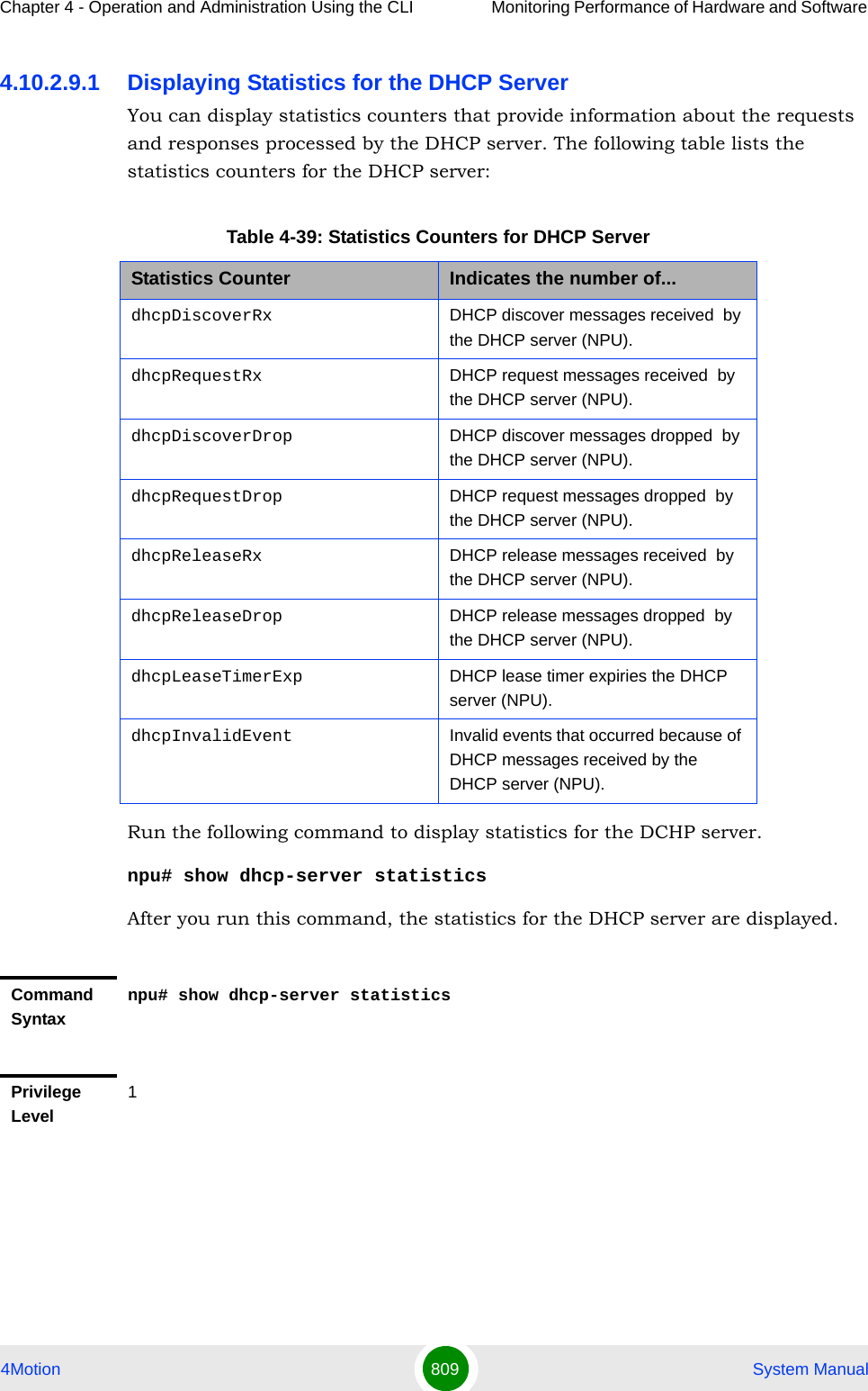
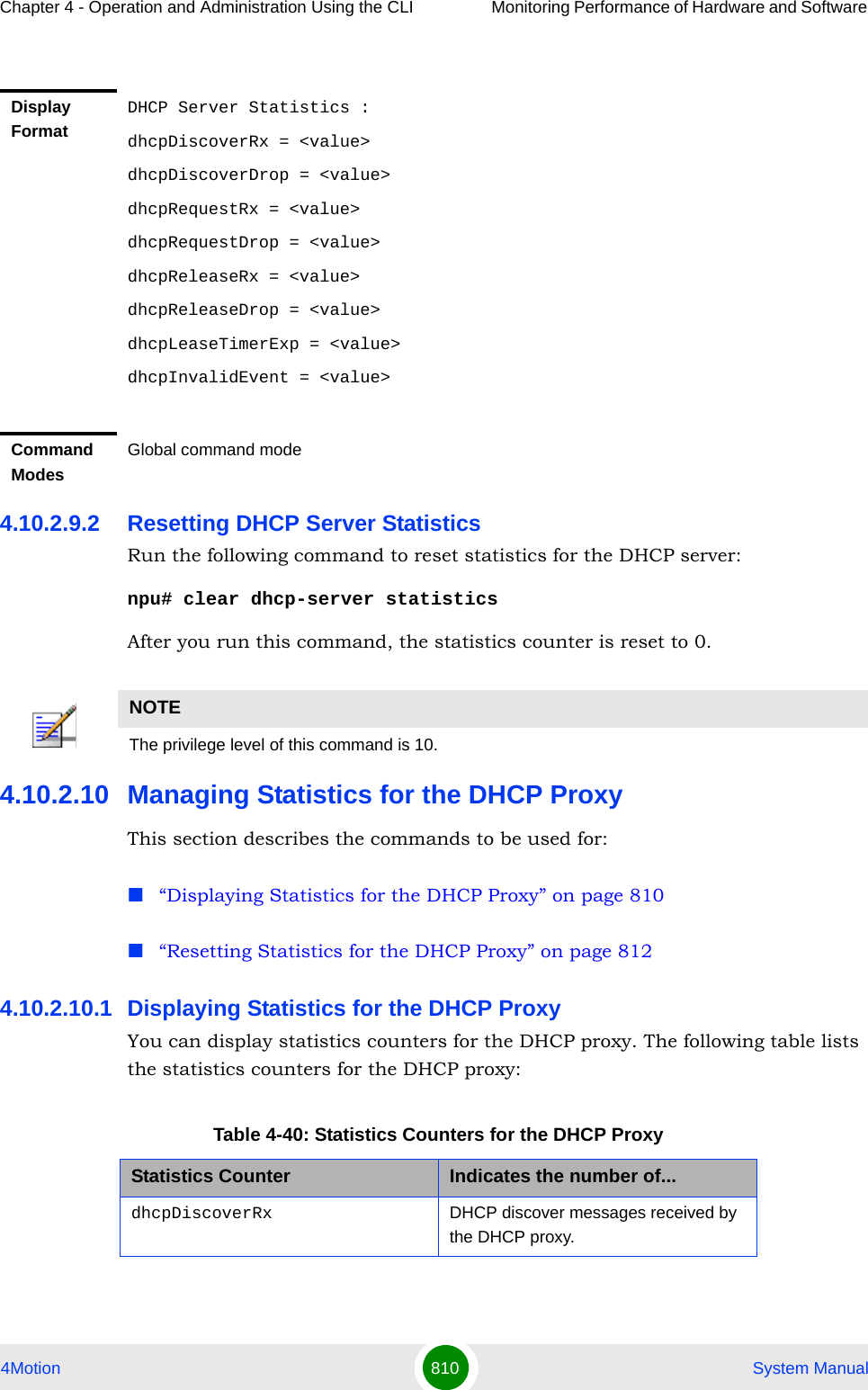
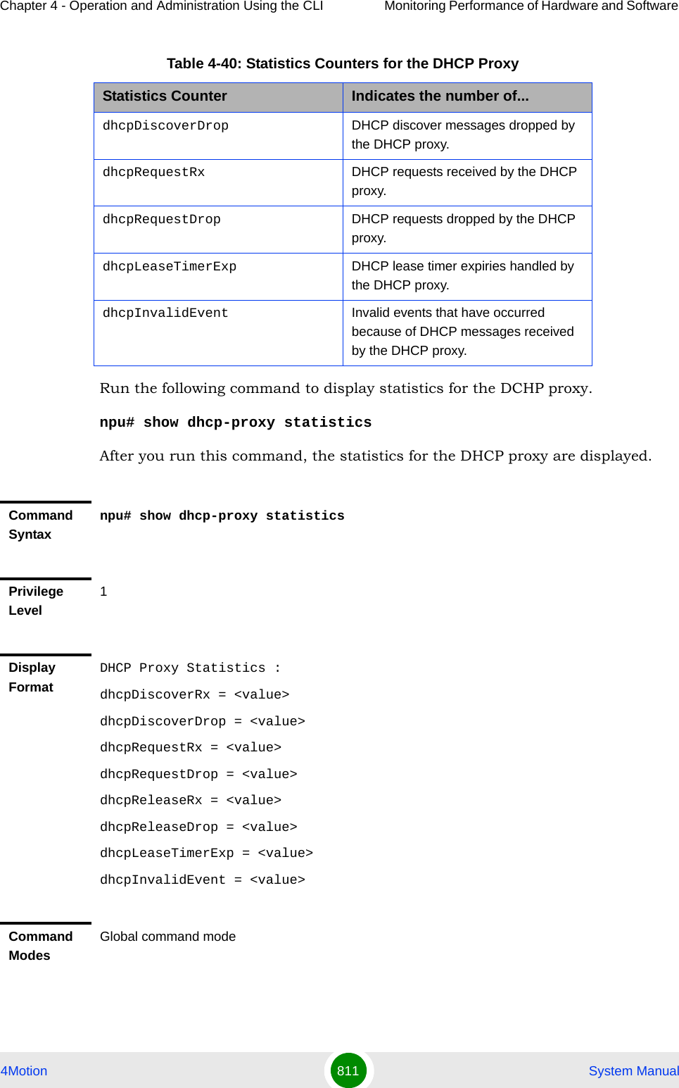
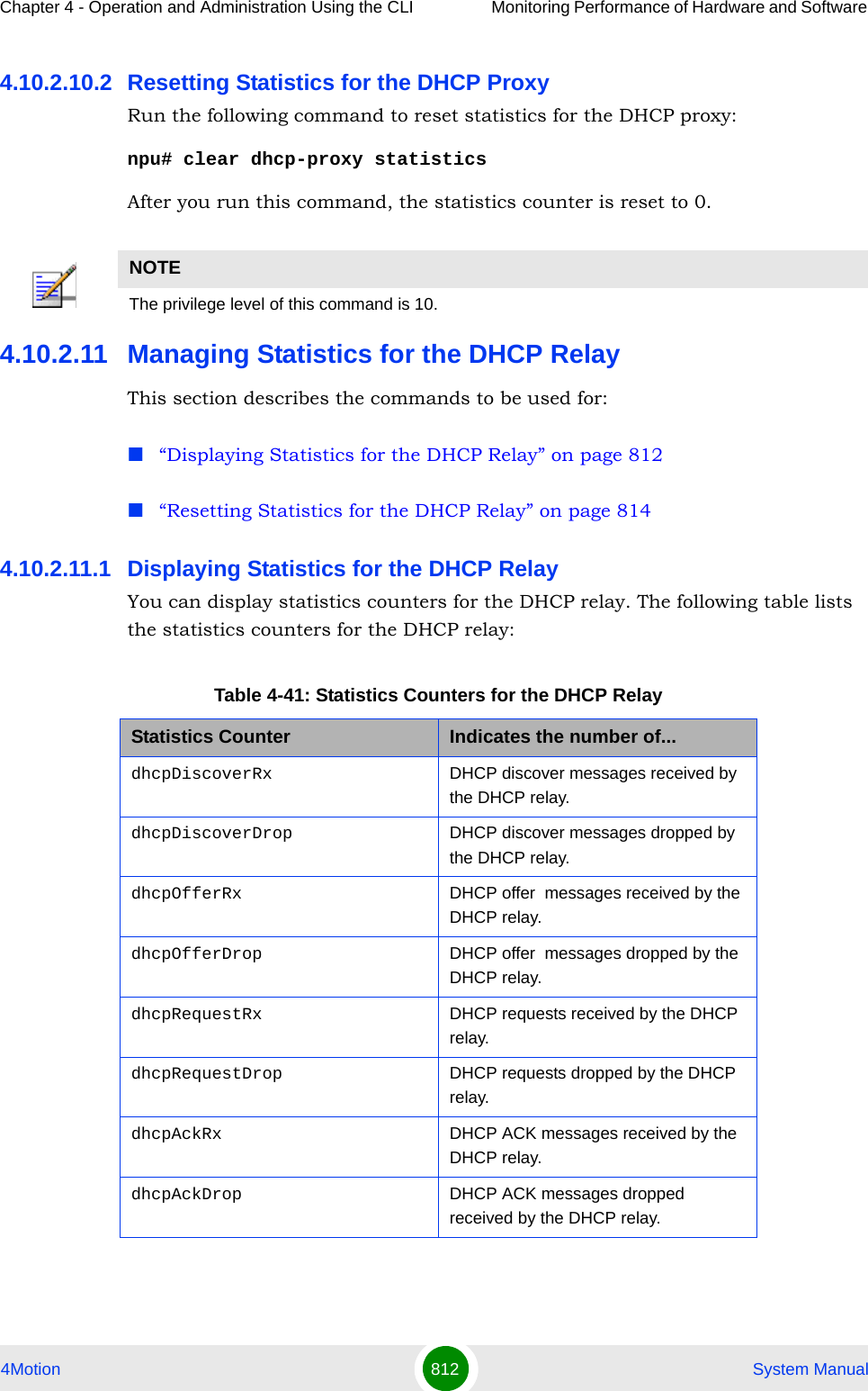
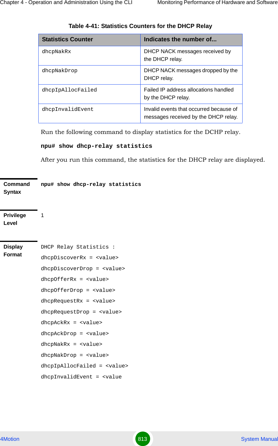
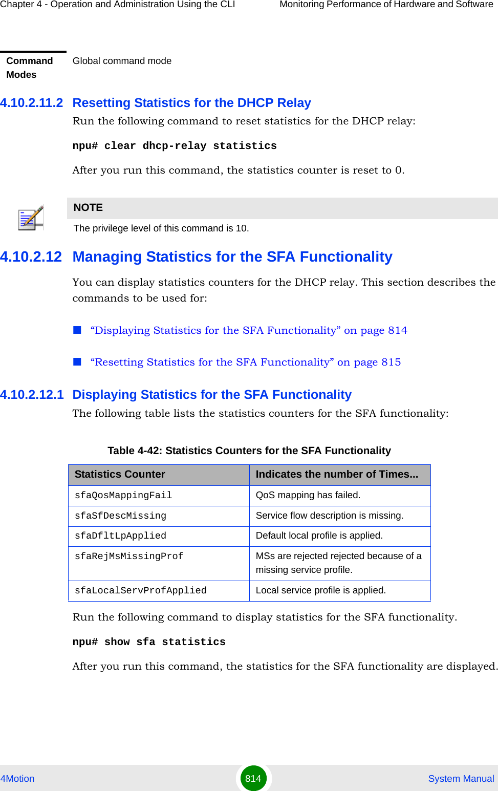
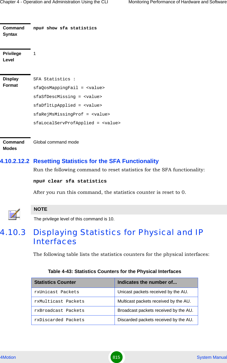
![Chapter 4 - Operation and Administration Using the CLI Monitoring Performance of Hardware and Software 4Motion 816 System ManualThe following table lists the statistics counters for the physical and IP interfaces:Run the following command to display the statistics for physical and IP interfaces:npu# show interfaces [{[<interface-type> <interface-id>] | internal-mgmt | external-mgmt | bearer | local-mgmt}] countersThe following table lists parameters to be used with respect to the type of interface:rxError Packets Erroneous packets received by the AU.rxUnknown Packets Unknown packets received by the AU.txBytes Bytes transmitted by the AU.txUnicast Packets Unicast packets transmitted by the AU.txBroadcast Packets Broadcast packets transmitted by the AU.txMulticast Packets Multicast packets transmitted by the AU.txDiscarded Packets Discarded packets transmitted by the AU.txError Packets Erroneous packets transmitted by the AU.Table 4-44: Statistics Counters for the IP InterfacesStatistics Counter Indicates the number of...rxBytes Bytes received by an IP interface.rxUnicast Packets Unicast packets received by an IP interface.rxDiscarded Packets Discarded packets received by an IP interface.rxError Packets Error packets received by an IPinterface.txBytes Bytes transmitted by an IP interface.txUnicast Packets Unicast packets transmitted by an IP interface.Table 4-43: Statistics Counters for the Physical InterfacesStatistics Counter Indicates the number of...](https://usermanual.wiki/Alvarion-Technologies/BMAX-OR-25.Manual-4/User-Guide-1114032-Page-135.png)
![Chapter 4 - Operation and Administration Using the CLI Monitoring Performance of Hardware and Software 4Motion 817 System ManualTable 4-45: Parameters for Displaying Statistics for All Physical, IP, and Virtual InterfacesInterface Parameters ExamplePhysical InterfacesFast Ethernet:<interface-type> <interface-id>npu# show interfaces fastethernet 0/1 countersnpu# show interfaces fastethernet 0/2 countersnpu# show interfaces fastethernet 0/3 countersnpu# show interfaces fastethernet 0/4 countersnpu# show interfaces fastethernet 0/5 countersnpu# show interfaces fastethernet 0/6 countersnpu# show interfaces fastethernet 0/7 countersnpu# show interfaces fastethernet 0/8 countersGigabit Ethernet<interface-type> <interface-id>npu# show interfaces gigabitethernet 0/9 countersnpu# show interfaces gigabitethernet 0/10 countersIP Interfacesinternal-mgmt npu# show interfaces internal-mgmt countersexternal-mgmt npu# show interfaces external-mgmt countersbearer npu# show interfaces bearer counterslocal-mgmt npu# show interfaces local-mgmt countersIMPORTANTAn error may occur if:The interface type or interface ID you have specified is incorrect. Refer the syntax description for more information about the appropriate values for configuring these parameters.The IP interface does not exist for the configured connectivity and boot mode.Command Syntaxnpu# show interfaces [{[<interface-type> <interface-id>] | internal-mgmt | external-mgmt | bearer | local-mgmt}] countersPrivilege Level1](https://usermanual.wiki/Alvarion-Technologies/BMAX-OR-25.Manual-4/User-Guide-1114032-Page-136.png)
![Chapter 4 - Operation and Administration Using the CLI Monitoring Performance of Hardware and Software 4Motion 818 System ManualSyntax Description Parameter Description Presence Default ValuePossible Values[{[<interface-type> <interface-id>] | internal-mgmt | external-mgmt | bearer | local-mgmt}] countersIndicates the type of interface (physical or IP) for which statistics are to be displayed. Do not specify any value for this parameter if you want to display statistics for all physical and IP interfaces.Optional N/A Refer Table 4-45Display Format (Fast Ethernet/Gigabit Ethernet)Port = <value>rxUnicast Packets = <value>rxMulticast Packets = <value>rxBroadcast Packets = <value>rxDiscarded Packets = <value>rxError Packets = <value>rxUnknown Packets = <value>txBytes = <value>txUnicast Packets = <value>txBroadcast Packets = <value>txMulticast Packets = <value>txDiscarded Packets = <value>txError Packets = <value>](https://usermanual.wiki/Alvarion-Technologies/BMAX-OR-25.Manual-4/User-Guide-1114032-Page-137.png)
![Chapter 4 - Operation and Administration Using the CLI Monitoring Performance of Hardware and Software 4Motion 819 System Manual4.10.4 Displaying System FilesThe following system files reside in the TFTP boot directory of the NPU:Performance data files: Contain performance counters for system modules. (For more information about the modules for which you can configure collection and storage of performance data, refer Section 4.3.12. These files are available in the path, /tftpboot/management/performance.System log: Contain log and trace messages. (For more information about configuring logging and tracing, refer Section 4.11.1 and Section 4.3.11. These files are available in the path, /tftpboot/management/system_log.Active alarms: Contain a list of currently active alarms. These files are residing in the path, /tftpboot/management/fault.User history files: Contain information about the commands/tasks executed by the user. These files are available in the path, /tftpboot/management/user_log.To display a list of performance data, system log, active alarms, or user history files, run the following command:npu# show saved {Performance | Active-alarm | Log | User-history} files [recent <1-65535>]For example, if you want to view the 30 most recently saved log files, residing in the TFTP boot directory of the NPU, run the following command:npu# show saved Log files recent 30Display Format (IP Interfaces)Port = <IP Interface Name>rxBytes = <value>rxUnicast Packets = <value>rxDiscarded Packets = <value>rxError Packets = <value>txBytes = <value>txUnicast Packets = <value>Command ModesGlobal command mode](https://usermanual.wiki/Alvarion-Technologies/BMAX-OR-25.Manual-4/User-Guide-1114032-Page-138.png)
![Chapter 4 - Operation and Administration Using the CLI Monitoring Performance of Hardware and Software 4Motion 820 System ManualCommand Syntaxnpu# show saved {Performance | Active-alarm | Log | User-history} files [recent <1-65535>]Privilege Level1Syntax Description Parameter Description Presence Default ValuePossible ValuesPerformance|Active-alarm|Log|User-historyIndicates the type of system files that are to be displayed:Mandatory N/A PerformanceActive-alarmLogUser-history[recent <1-65535>]Indicates the number of files to be displayed. The most recently saved files are displayed.If you do not specify a value for this parameter, all the files of a particular type are displayed.Optional N/A 1-65355Command ModesGlobal command mode](https://usermanual.wiki/Alvarion-Technologies/BMAX-OR-25.Manual-4/User-Guide-1114032-Page-139.png)
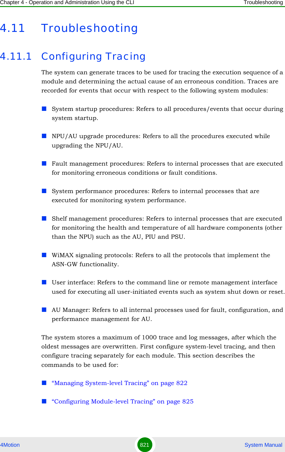
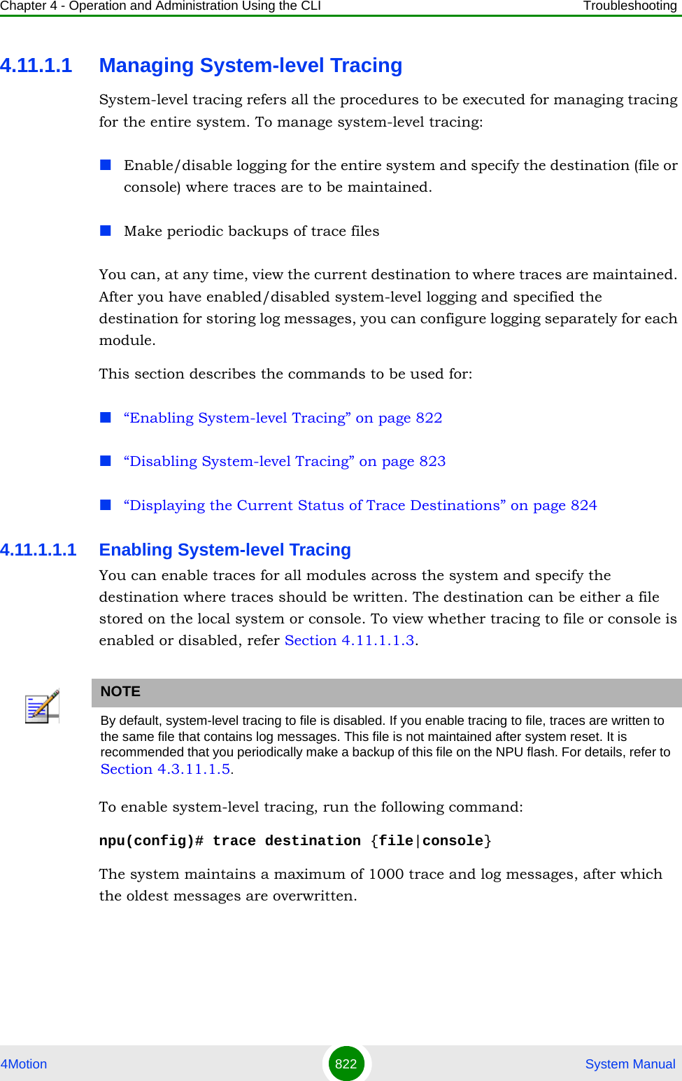
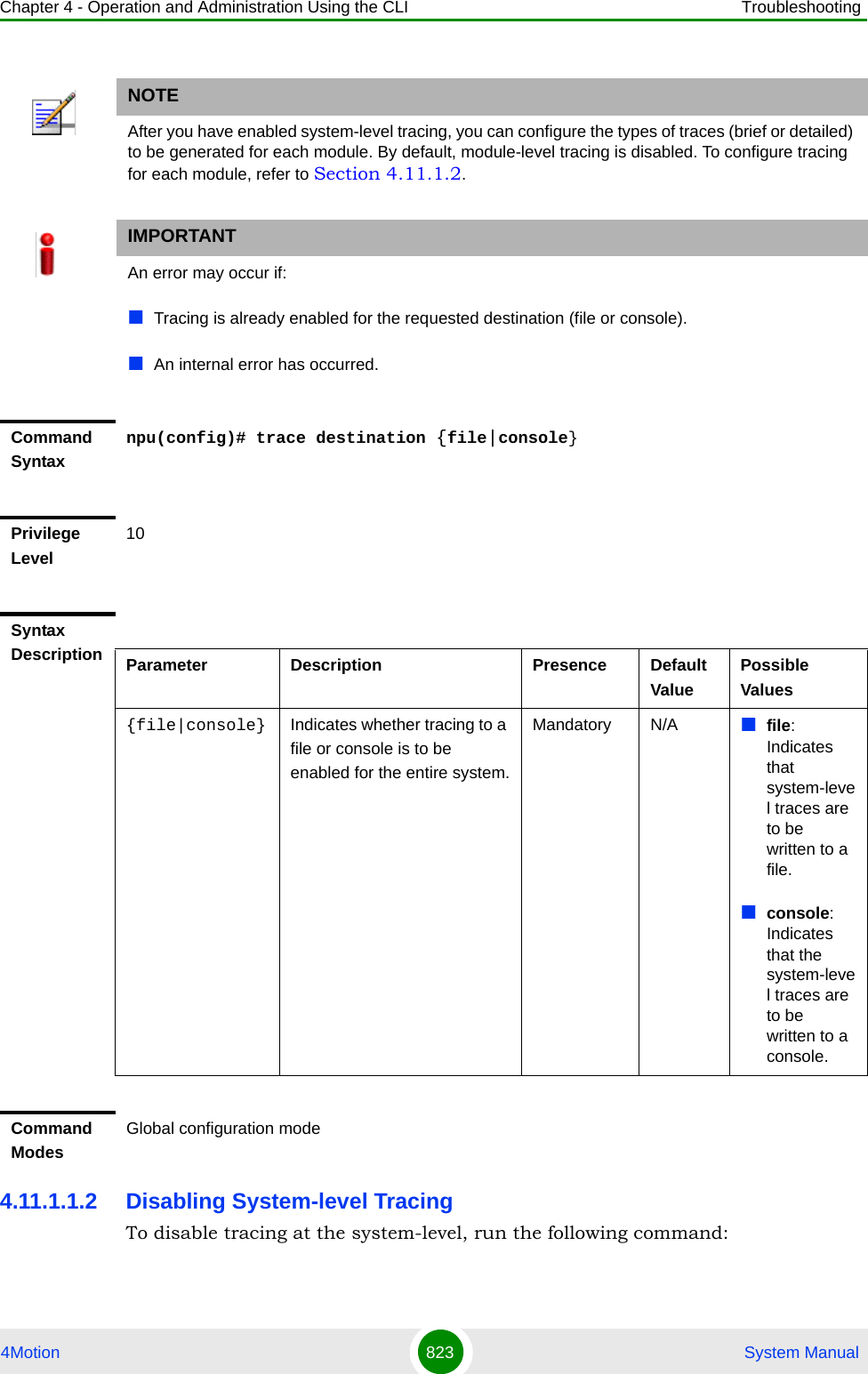
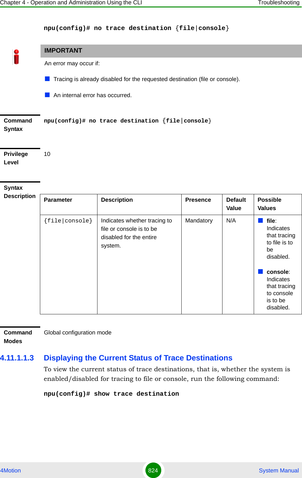
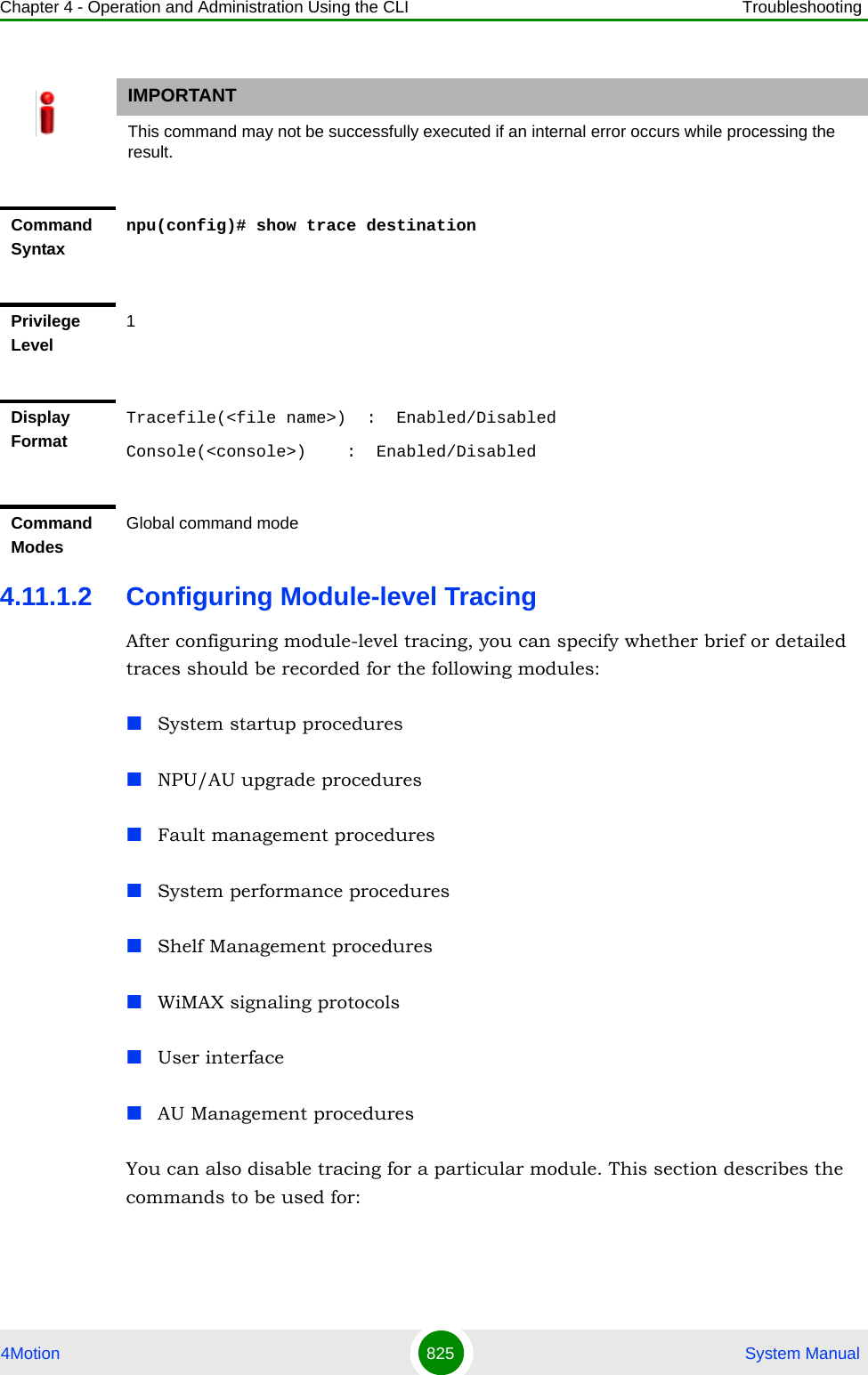
![Chapter 4 - Operation and Administration Using the CLI Troubleshooting4Motion 826 System Manual“Configuring Trace Levels” on page 826“Disabling Module-level Tracing” on page 827“Displaying Trace Levels” on page 8284.11.1.2.1 Configuring Trace LevelsTo specify the trace level (brief or detailed) for each module, run the following command:npu(config)# trace level [{StartupMgr|SWDownload|FaultMgr|PerfMgr|ShelfMgr|SIGASN|UserIF|AUMgr}] {Brief|Detailed}The parameters in this command correspond to the system modules/procedures listed in the following table:Specify the module name if you want to configure the trace level separately for this module. If you do not specify the name of the module, the trace level that you configure in this command is applied to all modules. For example, run the following command if you want logs to be created for WiMAX signaling protocols when the trace level configured to Detailed:npu(config)# trace level SIGASN DetailedNOTEBy default, module-level tracing is disabled.Table 4-46: Modules for which Tracing can be EnabledParameter Refers to...StartupMgr System startup proceduresSWDownload Software upgrade proceduresFaultMgr Fault management proceduresShelfMgr Shelf management proceduresSIGASN WiMAX signaling protocolsUserIF User-initiated proceduresAUMgr Internal processes used for managing AUPerfMgr Performance management procedures](https://usermanual.wiki/Alvarion-Technologies/BMAX-OR-25.Manual-4/User-Guide-1114032-Page-145.png)
![Chapter 4 - Operation and Administration Using the CLI Troubleshooting4Motion 827 System Manual4.11.1.2.2 Disabling Module-level TracingTo disable tracing for one or all modules, run the following command:npu(config)# no trace level [{StartupMgr|SWDownload|FaultMgr|PerfMgr|ShelfMgr|SIGASN|UserIF|AUMgr}]Specify the module if you want to disable tracing for that module. If you do not specify the name of the module, tracing is disabled for all modules.For example, run the following command if you want to disable tracing for WiMAX signaling protocols:Command Syntaxnpu(config)# trace level [{StartupMgr|SWDownload|FaultMgr|PerfMgr|ShelfMgr|SIGASN|UserIF|AUMgr}] {Brief|Detailed}Privilege Level10Syntax Description Parameter Description Presence Default ValuePossible Values[{StartupMgr|SWDownload|FaultMgr|PerfMgr|ShelfMgr|SIGASN|UserIF|AUMgr}]Indicates the name of the module for which the trace level is to be configured. If you do not specify any value for this parameter, the same trace level is applied to all modules. For more information about these parameters, refer Table 4-46.Optional N/A StartupMgrSWDownloadFaultMgrPerfMgrShelfMgrSIGASNUserIFAUMgr{Brief|Detailed}Indicates the trace level to be applied for a particular or all modules. Mandatory N/A BriefDetailedCommand ModesGlobal configuration mode](https://usermanual.wiki/Alvarion-Technologies/BMAX-OR-25.Manual-4/User-Guide-1114032-Page-146.png)
![Chapter 4 - Operation and Administration Using the CLI Troubleshooting4Motion 828 System Manualnpu(config)# no trace level SIGASN4.11.1.2.3 Displaying Trace LevelsTo view the trace levels configured for one or more modules, run the following command: npu(config)# show trace level [{StartupMgr|SWDownload|FaultMgr|PerfMgr|ShelfMgr|SIGASN|UserIF|AUMgr}]Specify the module for which you want to view the configured trace level. If you do not specify the name of the module, the trace levels configured for all modules is displayed.Command Syntaxnpu(config)# no trace level [{StartupMgr|SWDownload|FaultMgr|PerfMgr|ShelfMgr|SIGASN|UserIF|AUMgr}]Privilege Level10Syntax Description Parameter Description Presence Default ValuePossible Values[{StartupMgr|SWDownload|FaultMgr|PerfMgr|ShelfMgr|SIGASN|UserIF|AUMgr}]Indicates the name of the module for which tracing is to be disabled. If you do not specify any value for this parameter, tracing is disabled for all functionalities. For more information about these parameters, refer Table 4-46.Optional N/A StartupMgrSWDownloadFaultMgrPerfMgrShelfMgrSIGASNUserIFAUMgr\Command ModesGlobal configuration mode](https://usermanual.wiki/Alvarion-Technologies/BMAX-OR-25.Manual-4/User-Guide-1114032-Page-147.png)
![Chapter 4 - Operation and Administration Using the CLI Troubleshooting4Motion 829 System Manual4.11.2 Configuring Port MonitoringThe port monitoring feature enables you to mirror all incoming and outgoing traffic on an interface to another interface. You can configure one interface as the destination interface to which traffic from multiple interfaces can be mirrored. This section describes the commands to be executed for enabling/disabling port monitoring for source and destination interfaces or displaying configuration information for a particular interface.To enable port monitoring, you are required to configure:Command Syntaxnpu(config)# show trace level [{StartupMgr|SWDownload|FaultMgr|PerfMgr|ShelfMgr|SIGASN|UserIF|AUMgr}]Privilege Level1Syntax Description Parameter Description Presence Default ValuePossible Values[{StartupMgr|SWDownload|FaultMgr|PerfMgr|ShelfMgr|SIGASN|UserIF|AUMgr}]Indicates the name of the module for which you want to display the configured trace levels.If you do not specify any value for this parameter, the trace levels for all modules are displayed. For more information about these parameters, refer Table 4-46.Optional N/A StartupMgrSWDownloadFaultMgrPerfMgrShelfMgrSIGASNUserIFAUMgrDisplay FormatModule Name : Trace level<module name> : <Trace Level>Command ModesGlobal command mode](https://usermanual.wiki/Alvarion-Technologies/BMAX-OR-25.Manual-4/User-Guide-1114032-Page-148.png)
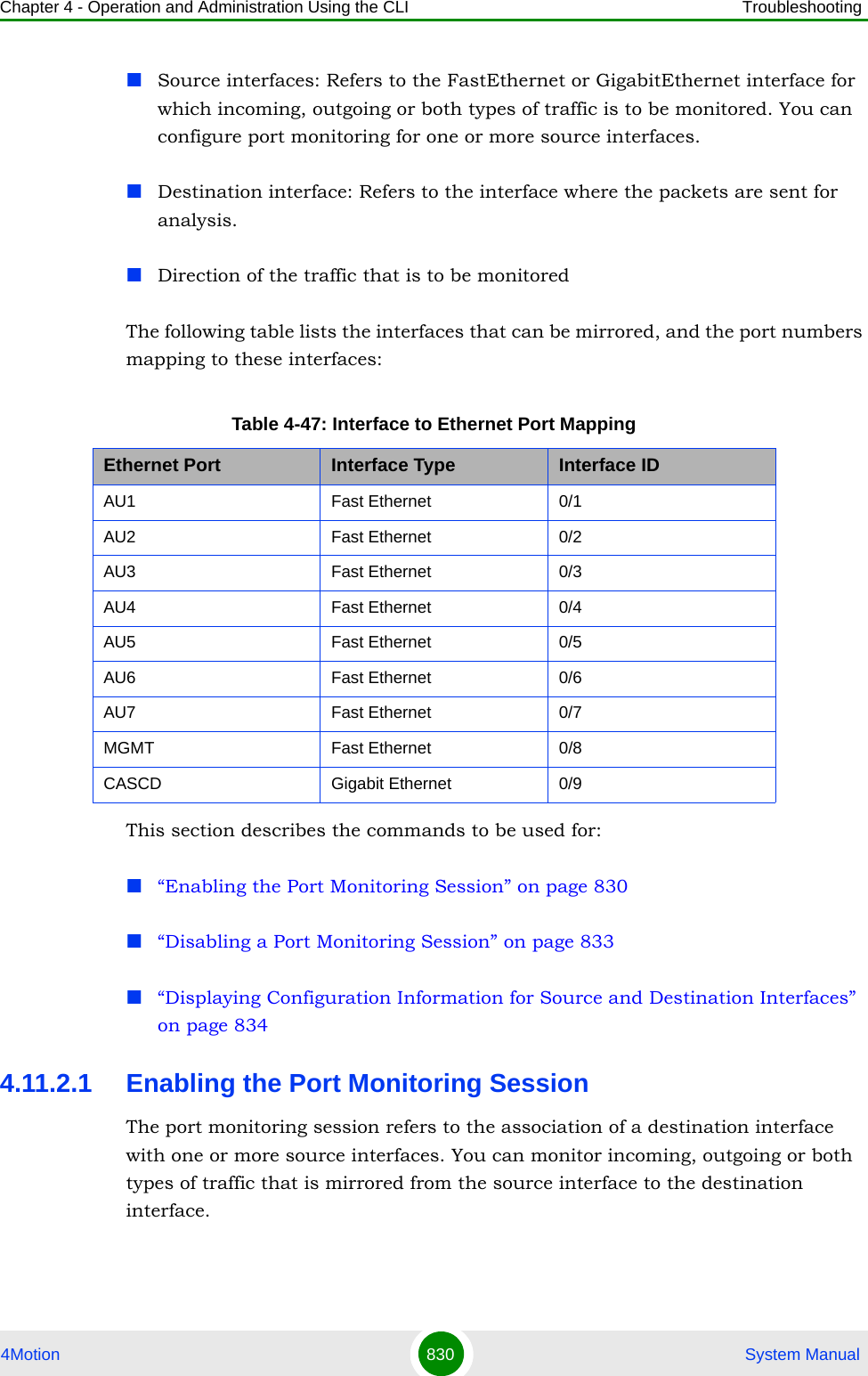
![Chapter 4 - Operation and Administration Using the CLI Troubleshooting4Motion 831 System ManualRun the following command to enable port monitoring for a source or destination interface:npu(config)# monitor session { destination interface <interface-type > <interface-id> | source interface <interface-type> <interface-id> [{ rx | tx | both }] }For example, to configure the Gigabit Ethernet 0/9 interface as the destination interface, you can run the following command:monitor session destination interface gigabitethernet 0/9You can now run the following commands to mirror incoming traffic for the source interfaces, Fast Ethernet 0/1 and Fast Ethernet 0/3:npu(config)# monitor session source interface fastethernet 0/1 rxnpu(config)# monitor session source interface fastethernet 0/3 rx All incoming and outgoing traffic for the 0/1 and 0/3 interfaces will be mirrored to the 0/9 interface.NOTEFor the current release, only one monitor session can be set up. This means that only one destination can be configured for one or more source interfaces.IMPORTANTAn error may occur if:The interface ID of the source or destination port you have specified is invalid. Refer Table 4-47 for the interface ID corresponding to each interface type.The port specified as the source interface is already specified as the destination interface for another port or vice versa.Command Syntaxnpu(config)# monitor session { destination interface <interface-type > <interface-id> | source interface <interface-type> <interface-id> [{ rx | tx | both }] }Privilege Level10](https://usermanual.wiki/Alvarion-Technologies/BMAX-OR-25.Manual-4/User-Guide-1114032-Page-150.png)
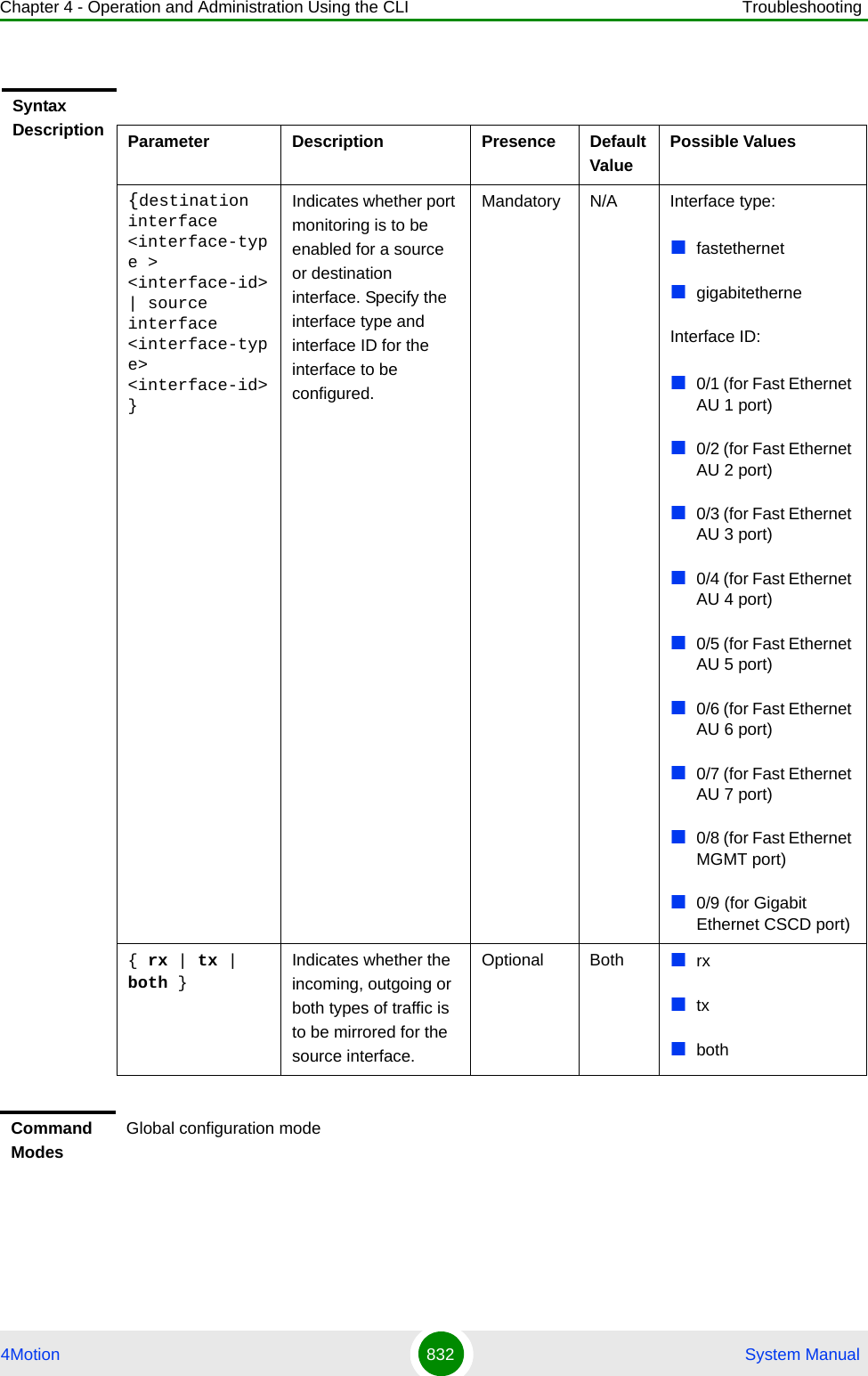
![Chapter 4 - Operation and Administration Using the CLI Troubleshooting4Motion 833 System Manual4.11.2.2 Disabling a Port Monitoring SessionYou can disable a port monitoring session for a source or destinations interface for which port monitoring is enabled. Run the following command to disable port monitoring for a source or destination interface:npu(config)# no monitor session [{source interface <interface-type> <interface-id> |destination interface <interface-type > < interface-id >}]IMPORTANTAn error may occur if:The interface ID of the source or destination port you have specified is invalid. Refer Table 4-47 for the interface ID corresponding to each interface type.Port monitoring is not enabled for the source or destination interface for which you are trying to disable port monitoring.Command Syntaxnpu(config)# no monitor session [{source interface <interface-type> <interface-id> |destination interface <interface-type > < interface-id >}]Privilege Level10](https://usermanual.wiki/Alvarion-Technologies/BMAX-OR-25.Manual-4/User-Guide-1114032-Page-152.png)
![Chapter 4 - Operation and Administration Using the CLI Troubleshooting4Motion 834 System Manual4.11.2.3 Displaying Configuration Information for Source and Destination InterfacesTo display configuration information for port monitoring, that is, the source and destination interfaces for which this feature is enabled, run the following command:Syntax Description Parameter Description Presence Default ValuePossible Values[{source interface <interface-type> <interface-id> |destination interface <interface-type > < interface-id >}]Indicates whether port monitoring is to be disabled for a source or destination interface. Specify the interface type and interface ID for the interface to be configured.Mandatory N/A Interface type:fastethernetgigabitetherneInterface ID:0/1 (for Fast Ethernet)0/2 (for Fast Ethernet)0/3 (for Fast Ethernet)0/4 (for Fast Ethernet)0/5 (for Fast Ethernet)0/6 (for Fast Ethernet)0/7 (for Fast Ethernet)0/8 (for Fast Ethernet)0/9 (for Gigabit Ethernet)Command ModesGlobal configuration mode](https://usermanual.wiki/Alvarion-Technologies/BMAX-OR-25.Manual-4/User-Guide-1114032-Page-153.png)
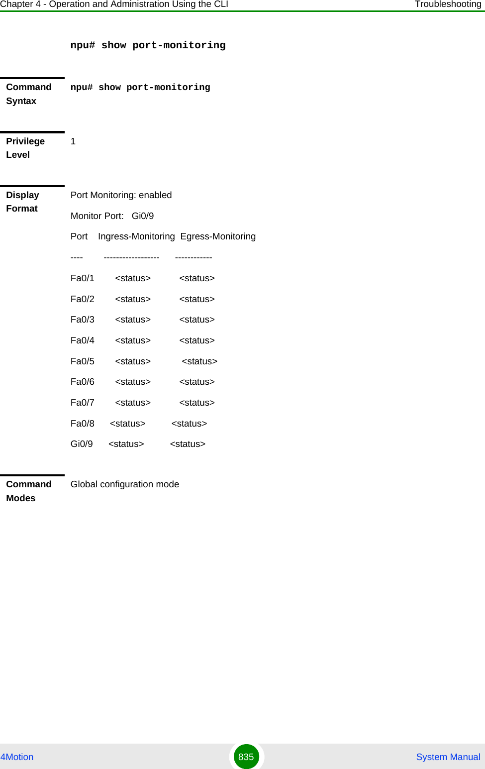
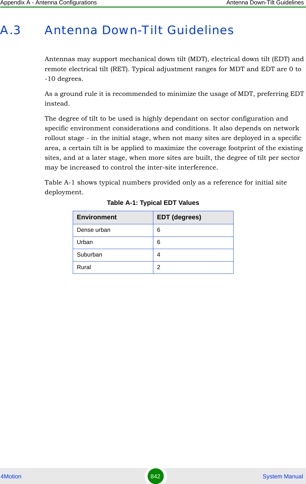

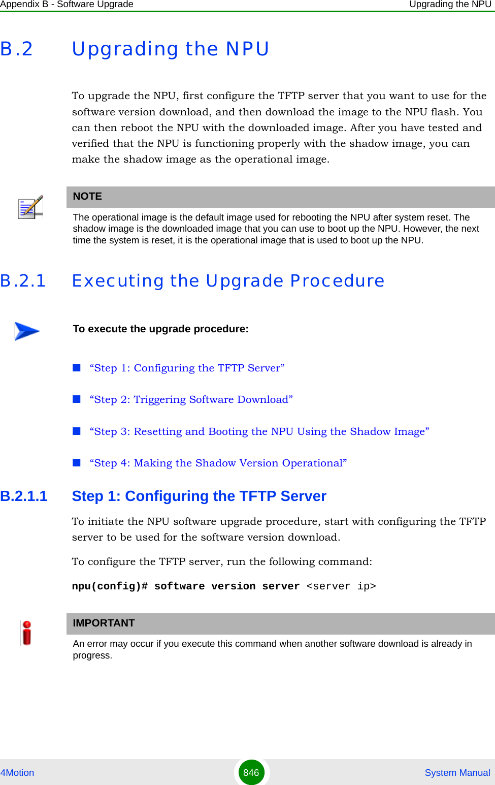
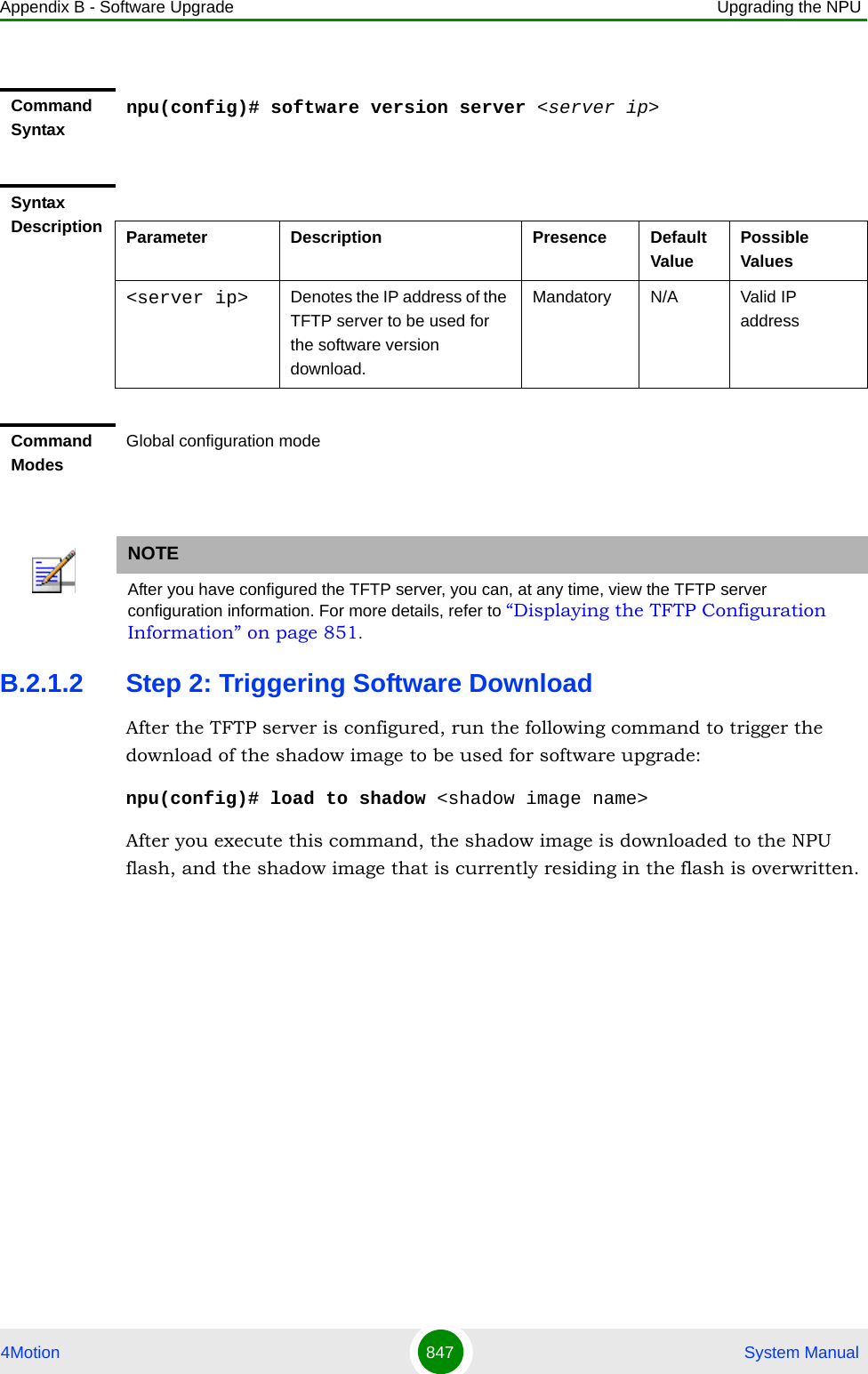
![Appendix B - Software Upgrade Upgrading the NPU4Motion 848 System ManualB.2.1.3 Step 3: Resetting and Booting the NPU Using the Shadow ImageAfter the shadow image is downloaded to the NPU flash, run the following command to reboot the NPU with the downloaded shadow image:npu(config)# reboot from shadow [<shadow image name>]IMPORTANTAn error may occur if you execute this command when:Another software download is already in progress.The shadow image to be downloaded is already residing in the NPU flash as the shadow or operational image.The TFTP server is not configured. For more information about configuring the TFTP server, refer to “Step 1: Configuring the TFTP Server” on page 846.The name of the shadow image to be downloaded is incorrect or the format of the file name is incorrect. Because the file to be downloaded is a compressed file, always be suffix the file name with .tgz.The NPU is running with the shadow image.Command Syntaxnpu(config)# load to shadow <shadow image name>Syntax Description Parameter Description Presence Default ValuePossible Values<shadow image name>Denotes the name of the shadow image that is to be downloaded to the NPU flash. The name of this file should always be suffixed with .tgz.Mandatory N/A <Valid shadow image name>.tgzCommand ModesGlobal configuration modeNOTEAfter you have triggered the download procedure, you can at any time, obtain information about the download status. For more details, refer to “Displaying the Download Status Information” on page 851.](https://usermanual.wiki/Alvarion-Technologies/BMAX-OR-25.Manual-4/User-Guide-1114032-Page-167.png)
![Appendix B - Software Upgrade Upgrading the NPU4Motion 849 System ManualIn the above command, you can specify the shadow image name that is to be used for NPU reboot. If you do not specify a value for the shadow image name parameter, the shadow image that was last downloaded is used for rebooting the NPU.B.2.1.4 Step 4: Making the Shadow Version OperationalAfter you reset the NPU with the shadow image, and ensure that the NPU is functioning correctly with the shadow image, you can make the shadow version as the operational version. The next time you reset the system, the shadow image that you make operational is used for rebooting the NPU. To make the shadow version as the operational version, run the following command.npu(config)# switchover npuAfter you run this command, the operational image is swapped with the shadow image. The next time you reset the NPU, the system boots up with the swapped image. Command Syntaxnpu(config)# reboot from shadow [<shadow image name>]Syntax Description Parameter Description Presence Default ValuePossible Value<shadow image name>Denotes the name of the shadow image that is to be used for rebooting the NPU.If you do not specify a value for this parameter, the last downloaded shadow image is used for rebooting the NPU.Optional N/A Valid shadow image nameCommand ModesGlobal configuration modeIMPORTANTIf you reset the NPU before running this command, the NPU boots up with the image that is currently the operational image.](https://usermanual.wiki/Alvarion-Technologies/BMAX-OR-25.Manual-4/User-Guide-1114032-Page-168.png)
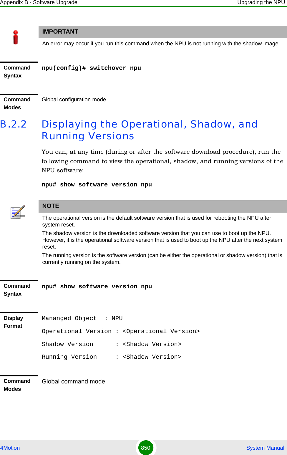
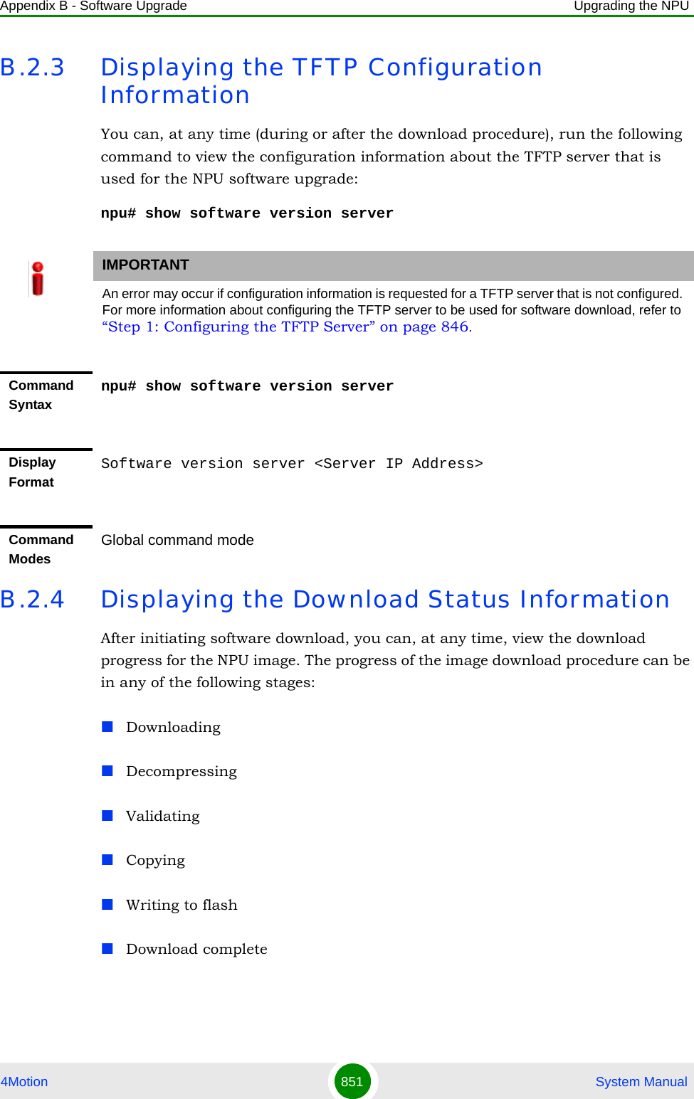
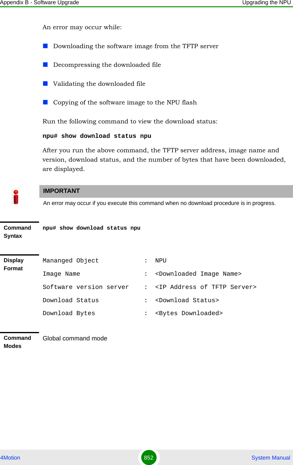
![Appendix B - Software Upgrade Upgrading the AU4Motion 853 System ManualB.3 Upgrading the AUTo upgrade the AU software, first configure the TFTP server that you want to use for software version download, and then download the image to the NPU flash. You can store up to three images to be used for AU upgrade. You are required to create a mapping between the AU slot and the image residing in the NPU flash. Each time the AU is reset or if you are inserting/re-inserting the AU card in the AU slot for, the AU boots up using the AU-to-image mapping that you specify.You can specify separate AU-to-image mappings for each AU slot. In addition, you are required to create a mapping that is to be used as the default mapping. This default mapping is used for boot up all AU slots for which a mapping does not exist. After you have created the mapping, download the mapped image from the NPU flash to the AU flash (for the AU slot for which the mapping is created). You can then reboot the AU using the downloaded image.If the image that you have used to reboot the AU is not the image currently mapped to this AU slot, the AU-to-image mapping for that AU slot is updated with this image (provided you have not deleted this image from the NPU flash before rebooting the AU).B.3.1 Procedure for Upgrading the AU“Step 1: Configuring the TFTP Server” on page 854“Step 2: Downloading the AU Image to the NPU Flash” on page 855“Step 3: Creating the AU-to-Image Mapping” on page 856IMPORTANTBefore inserting an AU card, ensure that an AU-to-image mapping exists, which is to be used for booting the AU. If you insert the AU card when there is no existing mapping, the AU is immediately shut down. For more information about creating a (default) AU-to-image mapping, refer “Step 3: Creating the AU-to-Image Mapping” on page 856.After you create the AU-to-image mapping, execute the following command (for details refer Section B.3.1.5).npu(config)# reboot au [<au slot-id>] shadow [<shadow image name>]After you execute this comamnd, the AU boots up with the mapped image.To execute the AU upgrade procedure:](https://usermanual.wiki/Alvarion-Technologies/BMAX-OR-25.Manual-4/User-Guide-1114032-Page-172.png)
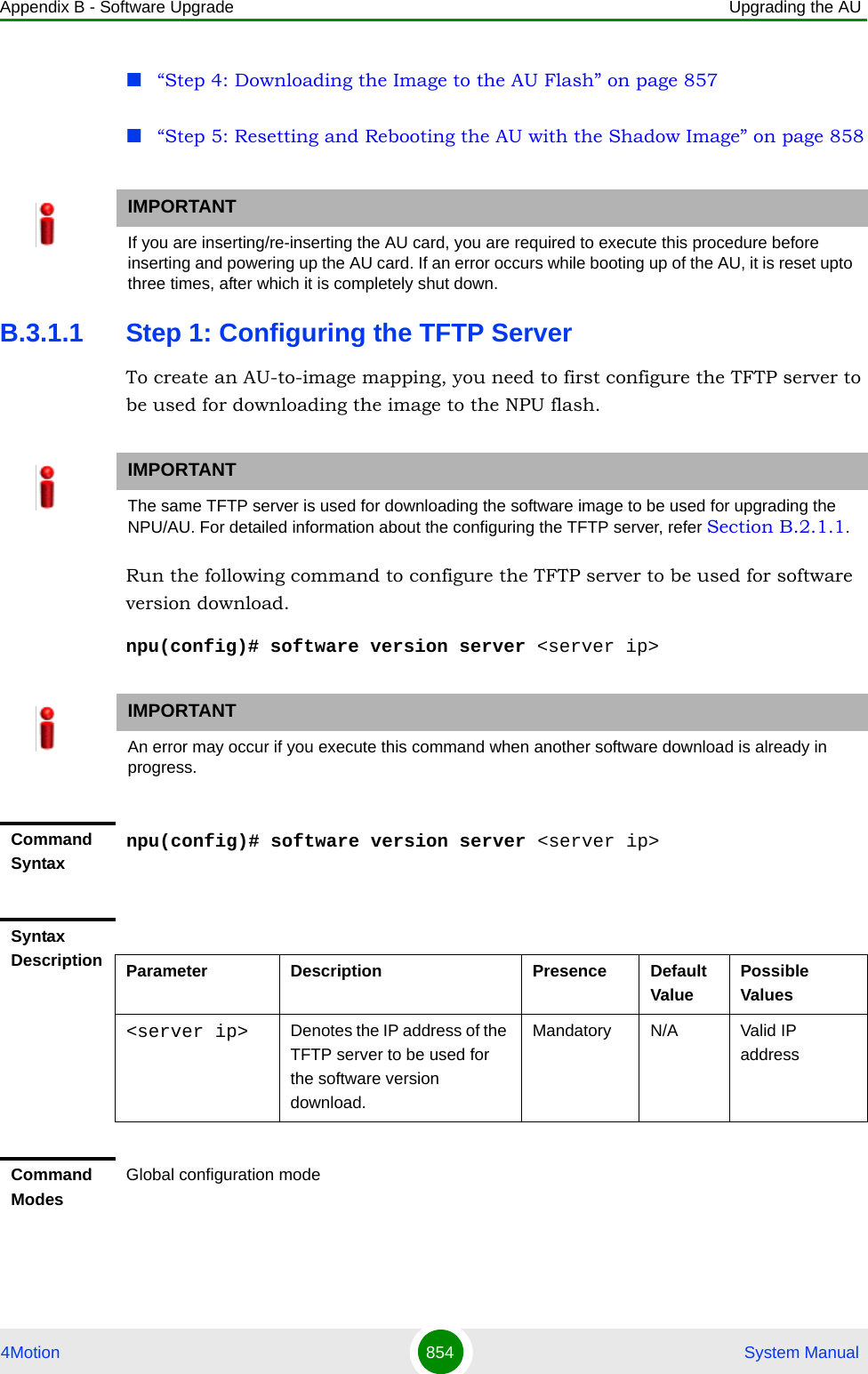
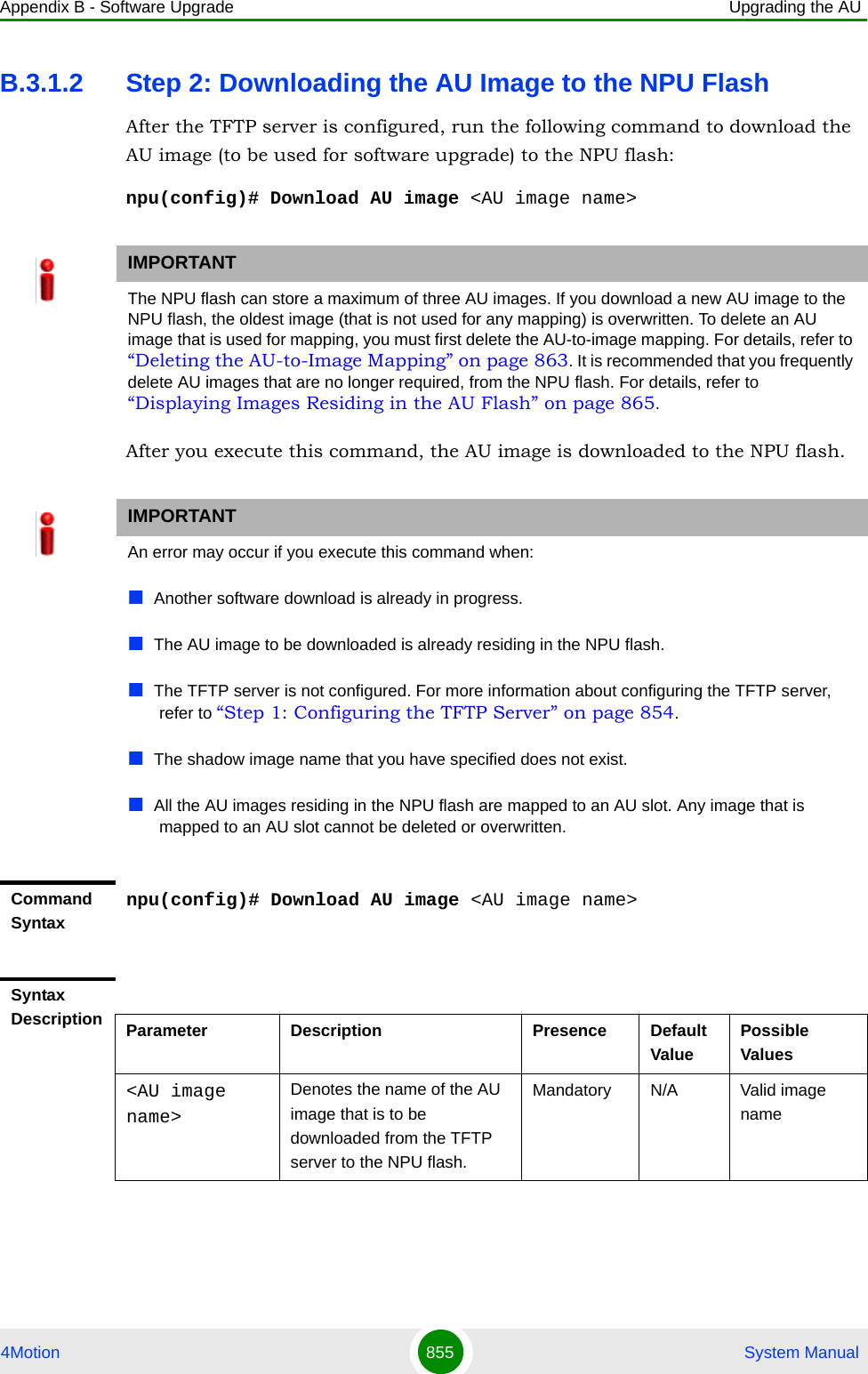
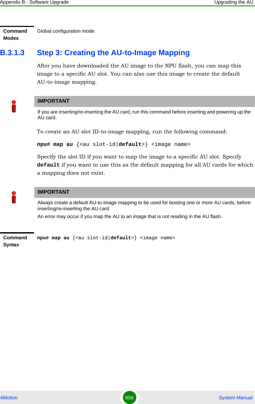
![Appendix B - Software Upgrade Upgrading the AU4Motion 857 System ManualB.3.1.4 Step 4: Downloading the Image to the AU FlashThe AU flash can store two AU images: shadow and operational. The operational image is the image that is currently mapped to the AU slot, and is used for booting the AU when the AU is reset. The shadow image is the image that is downloaded from the NPU flash. After you have created the AU-to-image mapping for a particular AU slot, download the image from the NPU flash to the AU flash. To download the image to the AU flash, run the following command.npu(config)# load to au [<au slot-id>] shadow <shadow image name>Syntax Description Parameter Description Presence Default ValuePossible Value<au slot-id|default> Indicates the AU to which the image is to be mapped.Mandatory N/A 1, 2, 3, 4, 7, 8, 9 (valid slot ID)default: if you want to create a default AU-to-image mapping that can be used by all AUs for which a mapping does not exist. <image name> Denotes the name of the image to be mapped to the AU slot.Mandatory N/A Valid image nameCommand ModesGlobal configuration mode](https://usermanual.wiki/Alvarion-Technologies/BMAX-OR-25.Manual-4/User-Guide-1114032-Page-176.png)
![Appendix B - Software Upgrade Upgrading the AU4Motion 858 System ManualB.3.1.5 Step 5: Resetting and Rebooting the AU with the Shadow ImageAfter you have downloaded the image to the AU flash, you can run the following command to reset the system and boot the AU with the shadow image. After you run the following command, the shadow image is used to boot the AU after it is reset. If the AU is successfully rebooted with the shadow image, then this image becomes the operational image for AU. If an error occurs in booting up the AU with the shadow image, the AU boots up with the operational image instead. IMPORTANTAn error may occur if:The AU image is not present in the NPU flashYou execute this command immediately after inserting the AU card, and it is still registering itself with the 4Motion system.An AU image is currently being downloaded to the AU flash.The AU software image version is incompatible with the AU hardware.Command Syntaxnpu(config)# load to au [<au slot-id>] shadow <shadow image name>Syntax Description Parameter Description Presence Default ValuePossible Value[<au slot-id>] Indicates the slot ID of the AU to which the image is to be downloaded from the NPU flash.Optional N/A 1, 2, 3, 4, 7, 8, 9 (Valid slot ID)shadow <shadow image name>Denotes the name of the shadow image to be downloaded from the NPU to the AU flash.Optional N/A Valid image nameCommand ModesGlobal configuration mode](https://usermanual.wiki/Alvarion-Technologies/BMAX-OR-25.Manual-4/User-Guide-1114032-Page-177.png)
![Appendix B - Software Upgrade Upgrading the AU4Motion 859 System ManualHowever, the AU is immediately shut down after it boots up with the operational image.npu(config)# reboot au [<au slot-id>] shadow [<shadow image name>]Specify the image name that you have used for creating the mapping in, “Step 3: Creating the AU-to-Image Mapping” on page 856. If you define another image name in this command, the AU-to-image mapping is updated with this image (provided this image is also residing in the NPU flash). Specify the slot ID if you want to reboot a specific AU slot with this image. If you want to reboot all the AU slots with this image, do not specify any slot ID. In addition, the mappings for all AUs are updated with this image.After you run this command, the software version that is used to reboot the AU is the operational version. This version will be used for rebooting after the next AU reset.IMPORTANTAn error may occur if:The AU image is not present in the NPU flash. You execute this command immediately after inserting the AU card, and it is still registering itself with the 4Motion system.The software image version is incompatible with the hardware.Rebooting the AU with the shadow image has failed. (The AU boots up with the operational image, and then initiates self-shut down.IMPORTANTDo not delete this image from the NPU flash because this image is used to boot up the AU the next timeit is reset . If you delete this image from the NPU flash, the default AU-to-image mapping will be used to reboot the AU.Command Syntaxnpu(config)# reboot au [<au slot-id>] shadow <shadow image name>](https://usermanual.wiki/Alvarion-Technologies/BMAX-OR-25.Manual-4/User-Guide-1114032-Page-178.png)
![Appendix B - Software Upgrade Upgrading the AU4Motion 860 System ManualB.3.2 Displaying the Shadow, Running, and Operational VersionsYou can, at any time (during or after the software download procedure), run the following command to view the shadow, running, and operational versions used for the AU:npu# show software version au [<au slot-id>]Specify the AU slot ID, if you want to view the software version for a specific AU slot. Do not specify the AU slot ID if you want to view the software versions used for all AU slots.Syntax Description Parameter Description Presence Default ValuePossible Value[<au slot-id>] Denotes the slot ID of the AU to be rebooted with the image residing in the AU flash.If you do not specify a value for this parameter, the image is used to reboot all AUs.Optional N/A 1, 2, 3 4, 7, 8, 9<shadow image name>Denotes the name of the AU image to be used for rebooting the AU. If you do not specify the name of the shadow image, the AU reboots with the shadow image residing in the AU flash.Mandatory N/A Valid shadow image nameCommand ModesGlobal configuration modeNOTEThe operational version is the default software version that is used for rebooting the AU after AU reset. The shadow version is the downloaded software version that you can use to boot the AU. However, the next time the system is reset, it is the operational software version that is used to boot the NPU.The running version is the software version (is either the operational or shadow version) that is currently running on the system.](https://usermanual.wiki/Alvarion-Technologies/BMAX-OR-25.Manual-4/User-Guide-1114032-Page-179.png)
![Appendix B - Software Upgrade Upgrading the AU4Motion 861 System ManualB.3.3 Displaying the Download Status InformationAfter initiating software download, you can, at any time, view the download progress for the AU image to the NPU flash. The progress of image download can be in any of the following stages:DownloadingValidatingCopyingCommand Syntaxnpu# show software version au [<au slot-id>]Syntax Description Parameter Description Presence Default ValuePossible Value[<au slot-id>] Indicates the AU slot ID for which information about the shadow, operational, and running images is to be displayed.If you do not specify a value for this parameter, information about the shadow, operational, and running images for all AUs is displayed.Optional N/A 1 , 2 3, 4, 7, 8, 9Command ModesGlobal configuration modeDisplay FormatMananged Object : AUAU Slot-ID : <au slot-d>Operational Version : <oper_ver>Shadow Version : <shaow_ver>Running Version : <running_ver>](https://usermanual.wiki/Alvarion-Technologies/BMAX-OR-25.Manual-4/User-Guide-1114032-Page-180.png)
![Appendix B - Software Upgrade Upgrading the AU4Motion 862 System ManualWriting to flashDownload completeAn error may occur while:Downloading the software image from the TFTP serverValidating the downloaded fileCopying of the software image to the NPU flashRun the following command to view the download status of the AU image to NPU flash:npu# show software download status auB.3.4 Displaying the AU-to-Image MappingYou can run the following command to view the AU-to-image mapping for a particular AU slot:npu# show au [{<au slot-id|default>}] mappingIMPORTANTAn error may occur if you execute this command when no download procedure is in progress.Command Syntaxnpu# show software download status auDisplay FormatMananged Object : AUImage Name : <Downloaded Image Name>Software version server : <Server IP address>Download Status : <Download Status>Download Bytes : <Download bytes>Command ModesGlobal configuration mode](https://usermanual.wiki/Alvarion-Technologies/BMAX-OR-25.Manual-4/User-Guide-1114032-Page-181.png)
![Appendix B - Software Upgrade Upgrading the AU4Motion 863 System ManualSpecify the AU slot ID to display the AU-to-image mapping for a specific AU slot. If you want to view the default AU-to-image mapping, specify default. If you do not specify the slot ID or default, all the AU-to-image mappings are displayed.B.3.5 Deleting the AU-to-Image MappingRun the following command to delete an existing AU-to-image mapping:npu# delete au <au slot-id> mappingSpecify the AU slot ID for which you want to delete the existing mapping. After you delete this mapping, the AU boots up using the default AU-to-image mapping after the next AU reset.Command Syntaxnpu# show au [{<au slot-id|default>}] mappingSyntax Description Parameter Description Presence Default ValuePossible Value<au slot-id|default>Indicates the AU for which the AU slot to image mapping is to be displayed.If you do not specify a value for this parameter, all the AU-to-image mappings are displayed.Mandatory N/A 1, 2, 3, 4, 7, 8, 9 (Valid slot ID)default: if you want to display the default AU-to-image mappingCommand ModesGlobal configuration modeDisplay Format AU slot id Software image<AU slot-id> <Image Name>Command Syntaxnpu# delete au <au slot-id> mapping](https://usermanual.wiki/Alvarion-Technologies/BMAX-OR-25.Manual-4/User-Guide-1114032-Page-182.png)
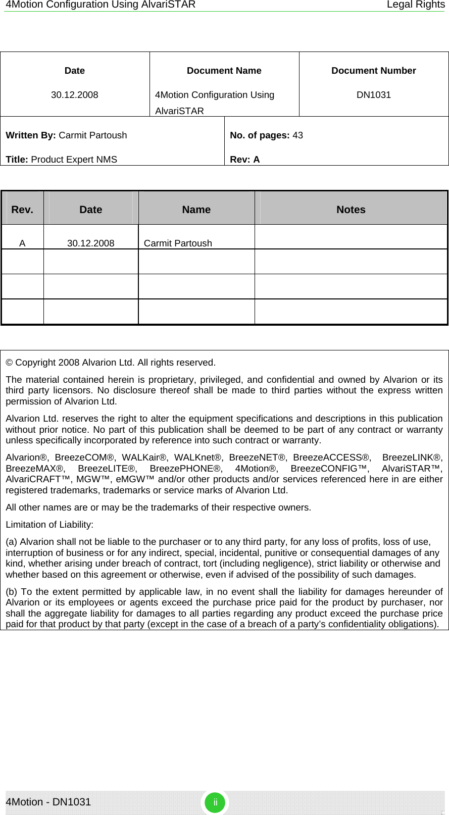
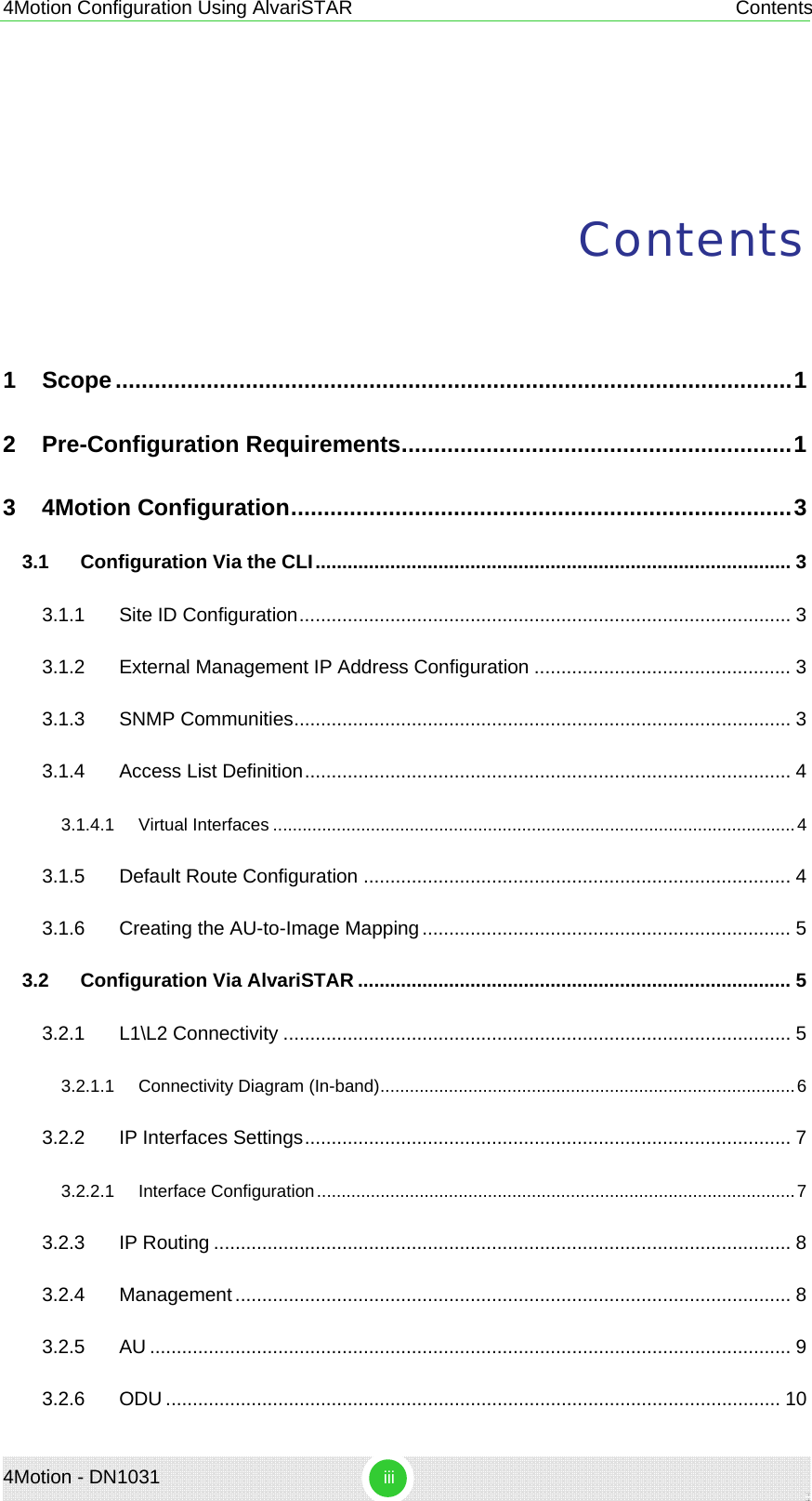
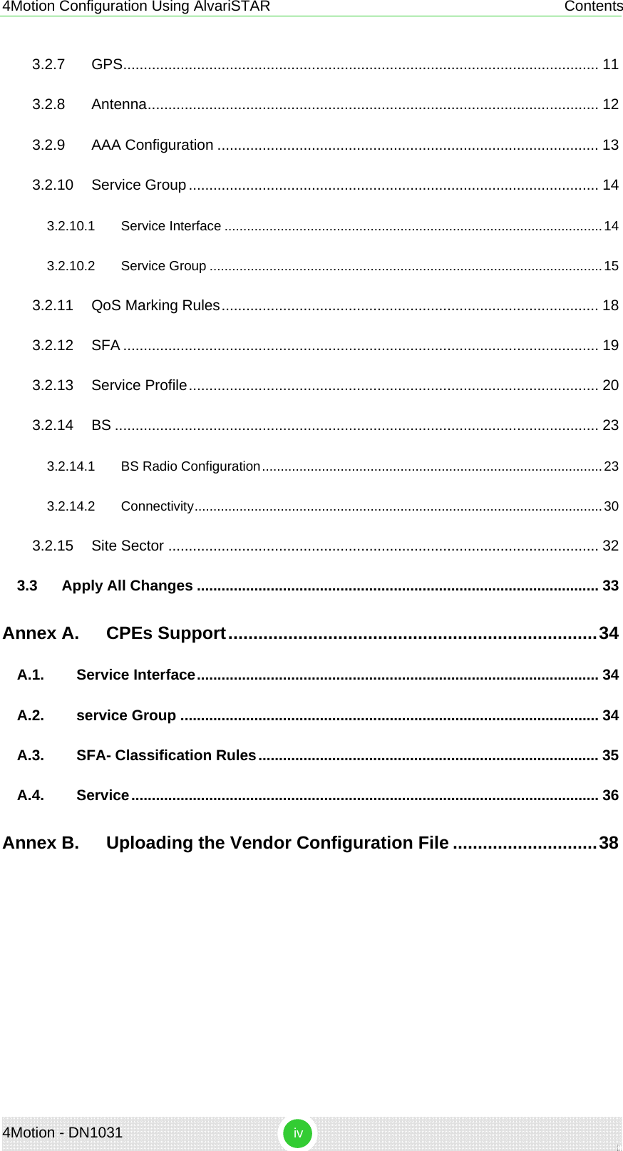
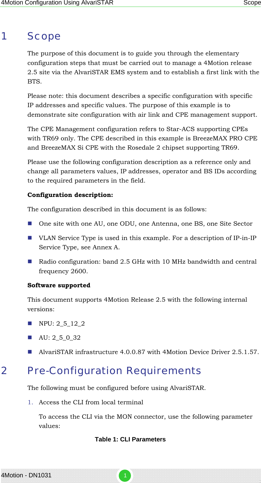
![4Motion Configuration Using AlvariSTAR Pre-Configuration Requirements Parameter Value Bit per second 115200 Data bits 8 Parity None Stop bits 1 Flow control Xon/Xoff NOTE The default login ID and password are: Login ID: root Password: admin123 2. Show Software Versions Before you start ensure that you have the correct software files available on the NPU card. ¾ Show NPU versions npu# show software version npu ¾ Show au versions npu# sh au image repository 3. Make the shadow version operational. This operation is performed only when that correct NPU version is located at the NPU's shadow npu(config)# switchover npu On the AU: npu(config)# load to au [<au slot-id>] shadow <shadow image name> 4. Clear the current NPU configuration Before you start, it is recommended to clean any existing configuration. NOTE All existing configuration will be deleted, including AU mapping and SW versions. npu# restore-factory-default The restore-factory-default command automatically performs NPU reset. 4Motion - DN1031 2](https://usermanual.wiki/Alvarion-Technologies/BMAX-OR-25.Manual-4/User-Guide-1114032-Page-191.png)