Alvarion Technologies BMAX-OR-25 BreezeMax 4Motion Broadband Wireless System User Manual 4Motion System Manual
Alvarion Technologies Ltd. BreezeMax 4Motion Broadband Wireless System 4Motion System Manual
UserManual.wiki
>
Alvarion Technologies
>
BMAX-OR-25 User Manual
>
Manual
Contents
1.
Manual 1
2.
Manual 2
3.
Manual 3
4.
Manual 4
5.
Manual
Manual
Navigation menu
Upload a User Manual
Namespaces
Wiki Guide
HTML
PDF
Info
Views
User Manual
Discussion / Help
Navigation

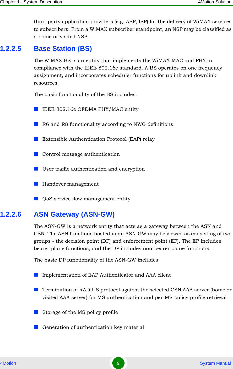
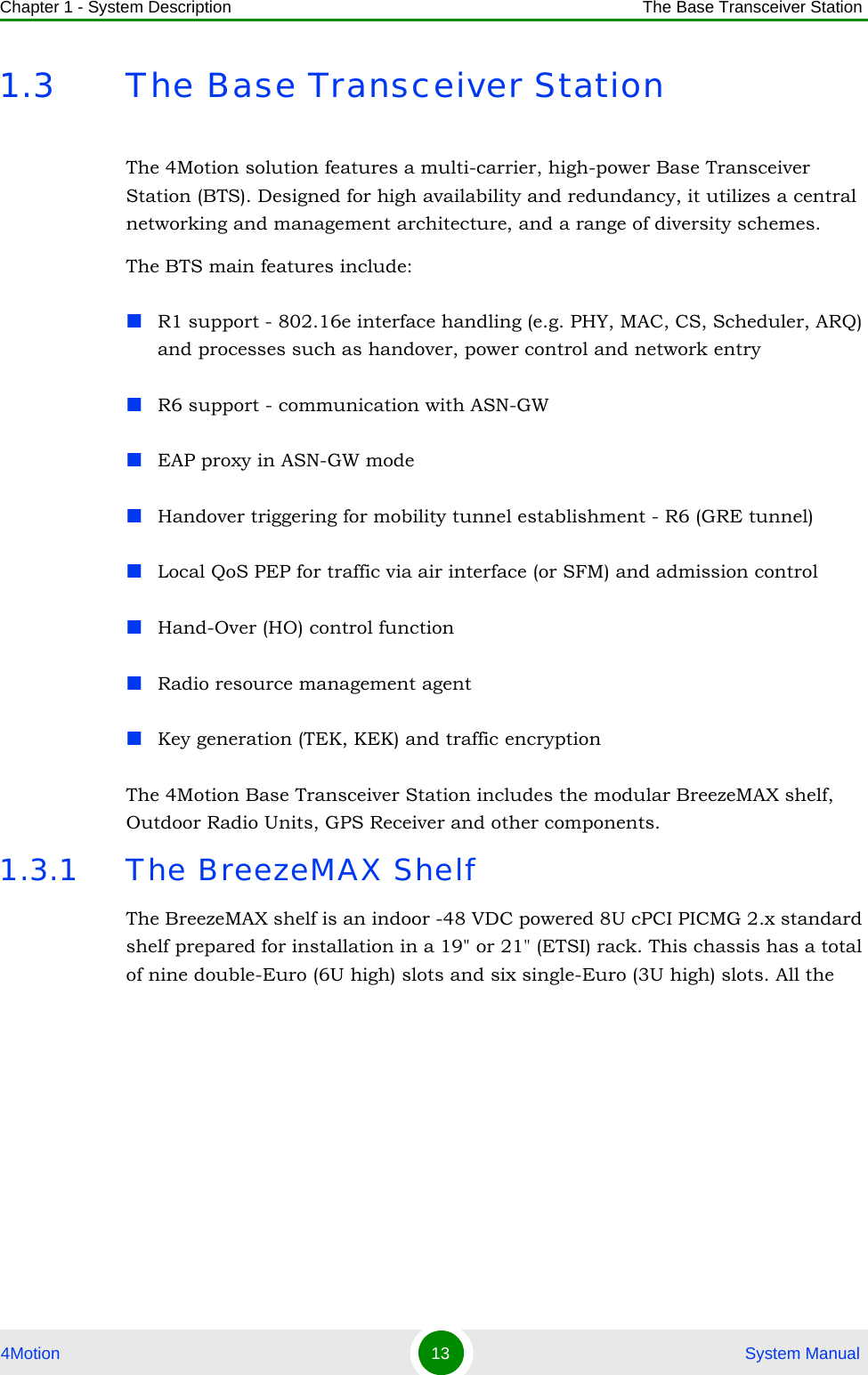
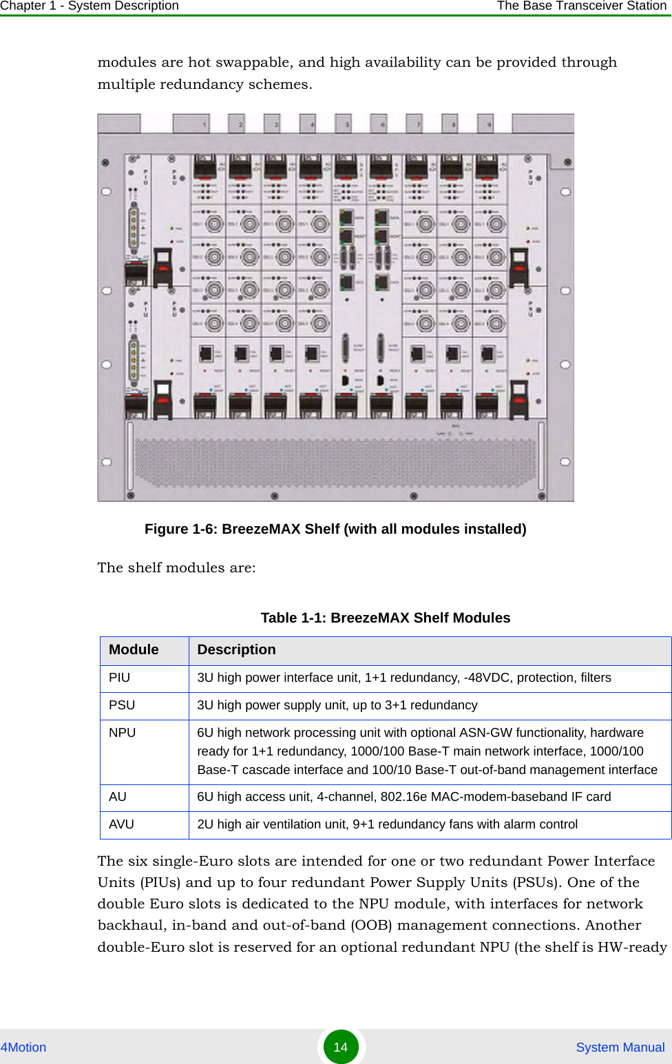
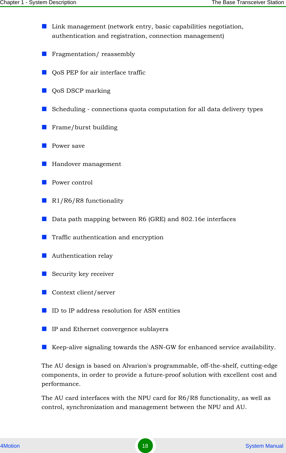
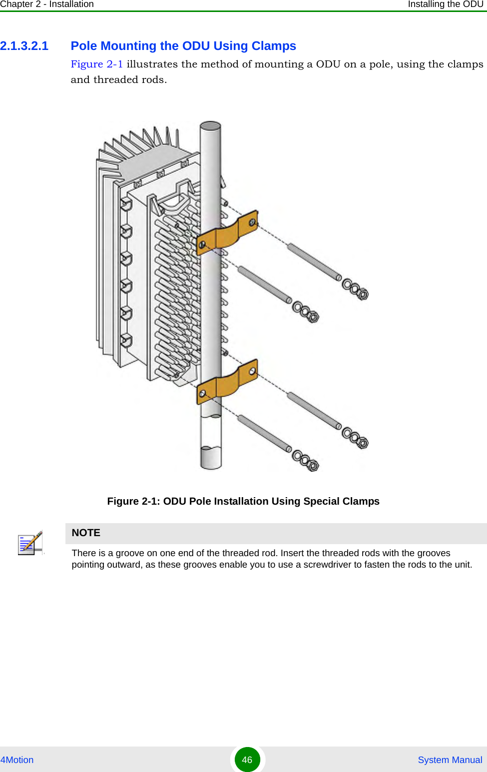
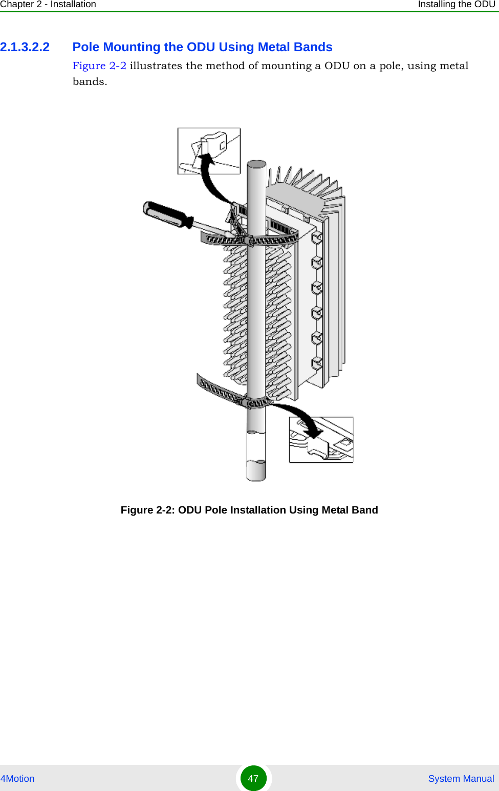
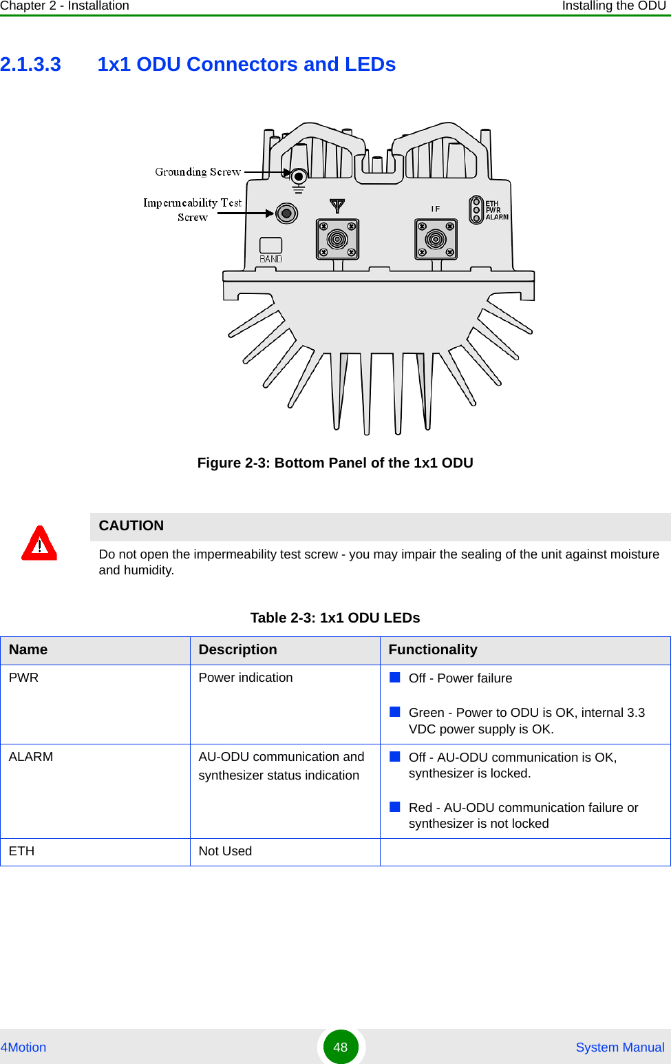
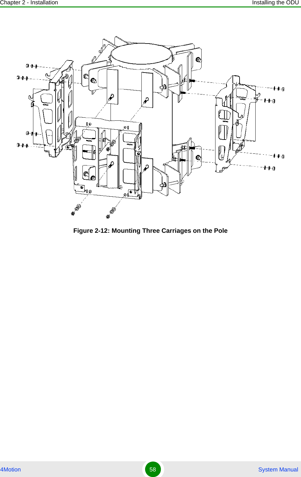
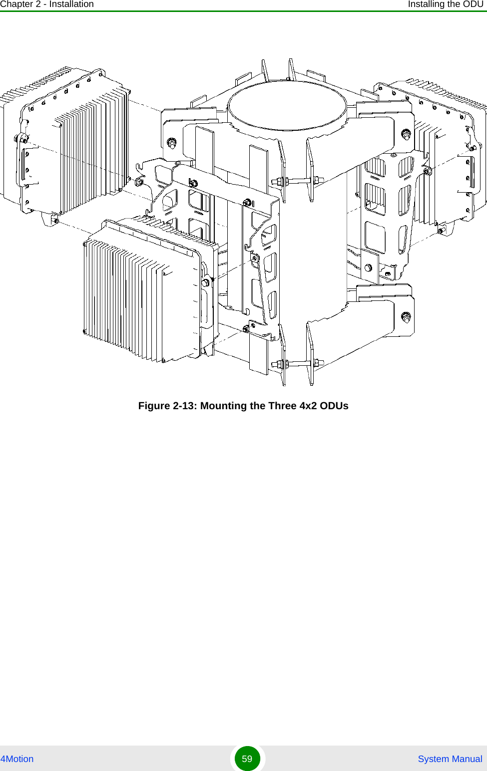
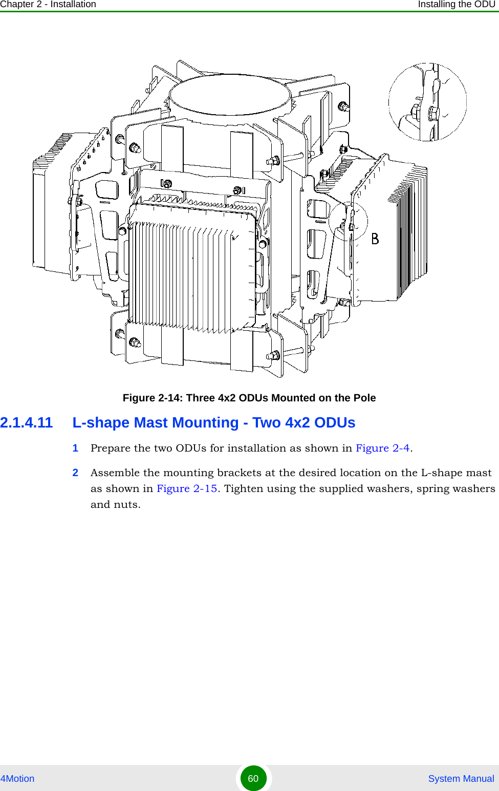
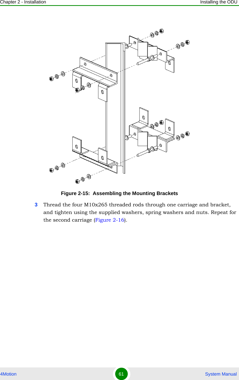
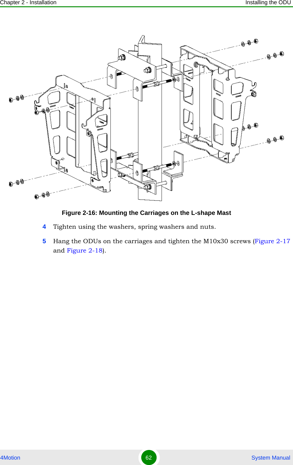
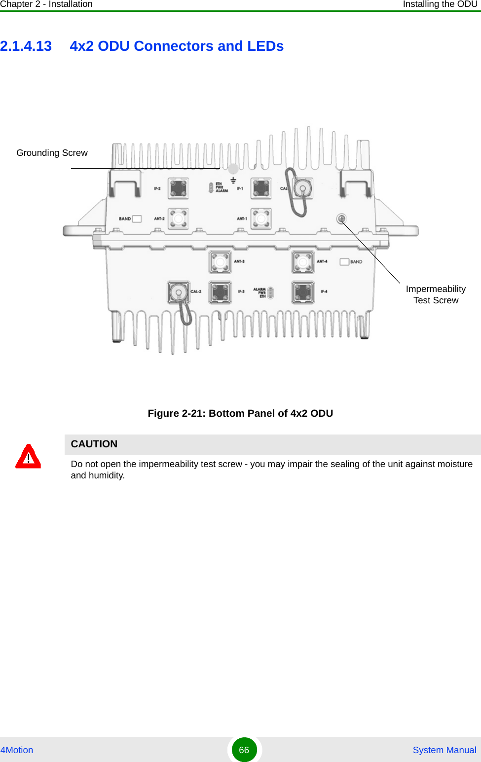
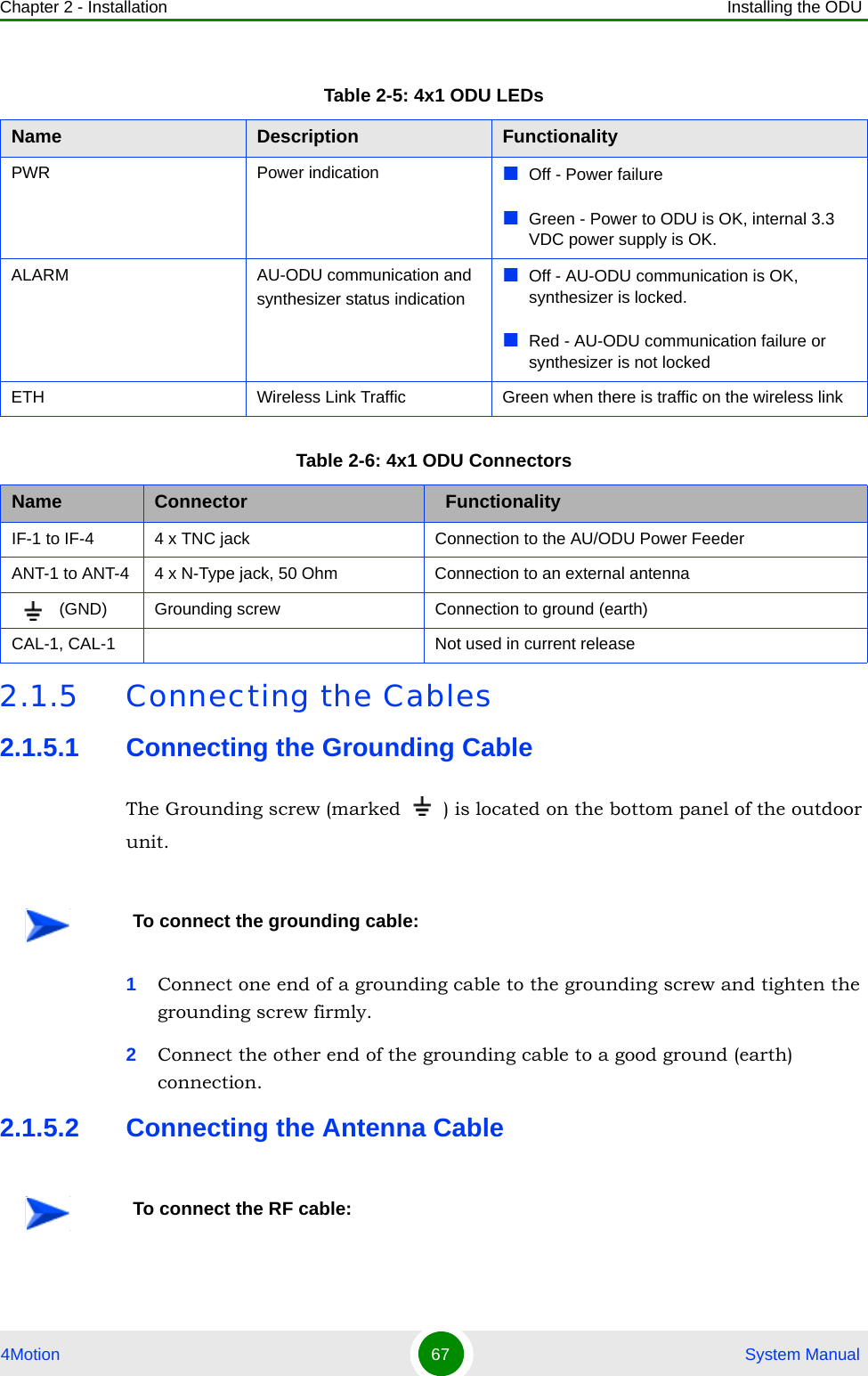
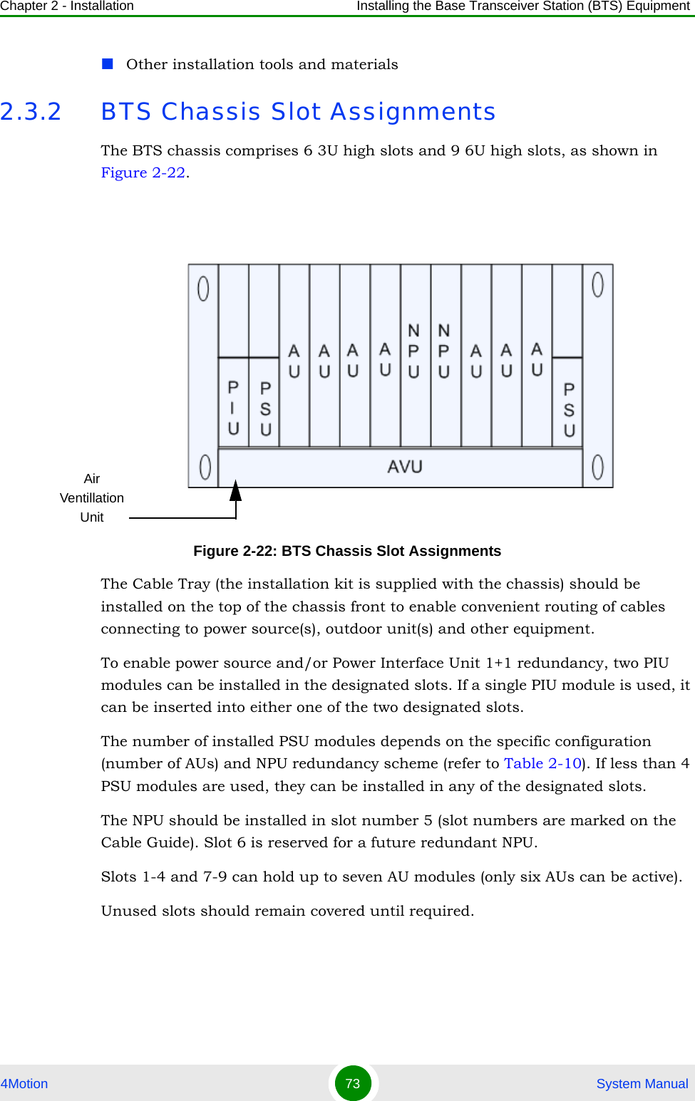
![Chapter 2 - Installation Installing the Outdoor GPS Receiver4Motion 95 System Manual2.5 Installing the Outdoor GPS ReceiverPerform the following steps to install the Outdoor GPS Receiver1Place the bracket on a flat surface and thread the supplied pipe through the bracket hole and into the GPS antenna. Hand-tighten until snug. Do not over-tighten or use a tool. Make sure that the connector (male) is on the open side of the bracket.2Assemble the surge protection cable onto the bracket using the supplied screws, washers, and spring washers (2x1032). Apply torque 2.1 [N*m] (19.2 [lbs*in]). Make sure that the female connector faces the antenna.3Use a 1032 screw, washer, and spring washer to connect the surge protector’s grounding cable to the bracket. Apply torque 2.1 [N*m] (19.2 [lbs*in]).4Connect the surge protector cable (female connector) to the GPS antenna connector (male). Use the groove on the cable connector (indicatd by an arrow) as a guide. It aligns with the tenon in the connector on the GPS side. Turn the locking ring on the cable connector clockwise to secure the connection. Do not over-tighten.5Use the supplied clamps to assemble the GPS and bracket on a pole. Use the M8 nuts, washers, and spring washers to lock the clamps to the bracket. Apply torque 9 [N*m] (80 [lbs*in]).](https://usermanual.wiki/Alvarion-Technologies/BMAX-OR-25.Manual/User-Guide-1150223-Page-114.png)