Alvarion Technologies BMAX-OR-25 BreezeMax 4Motion Broadband Wireless System User Manual 4Motion System Manual
Alvarion Technologies Ltd. BreezeMax 4Motion Broadband Wireless System 4Motion System Manual
Contents
- 1. Manual 1
- 2. Manual 2
- 3. Manual 3
- 4. Manual 4
- 5. Manual
Manual 3
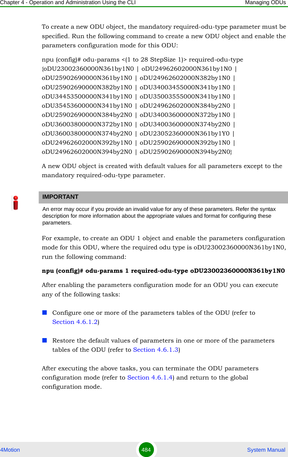
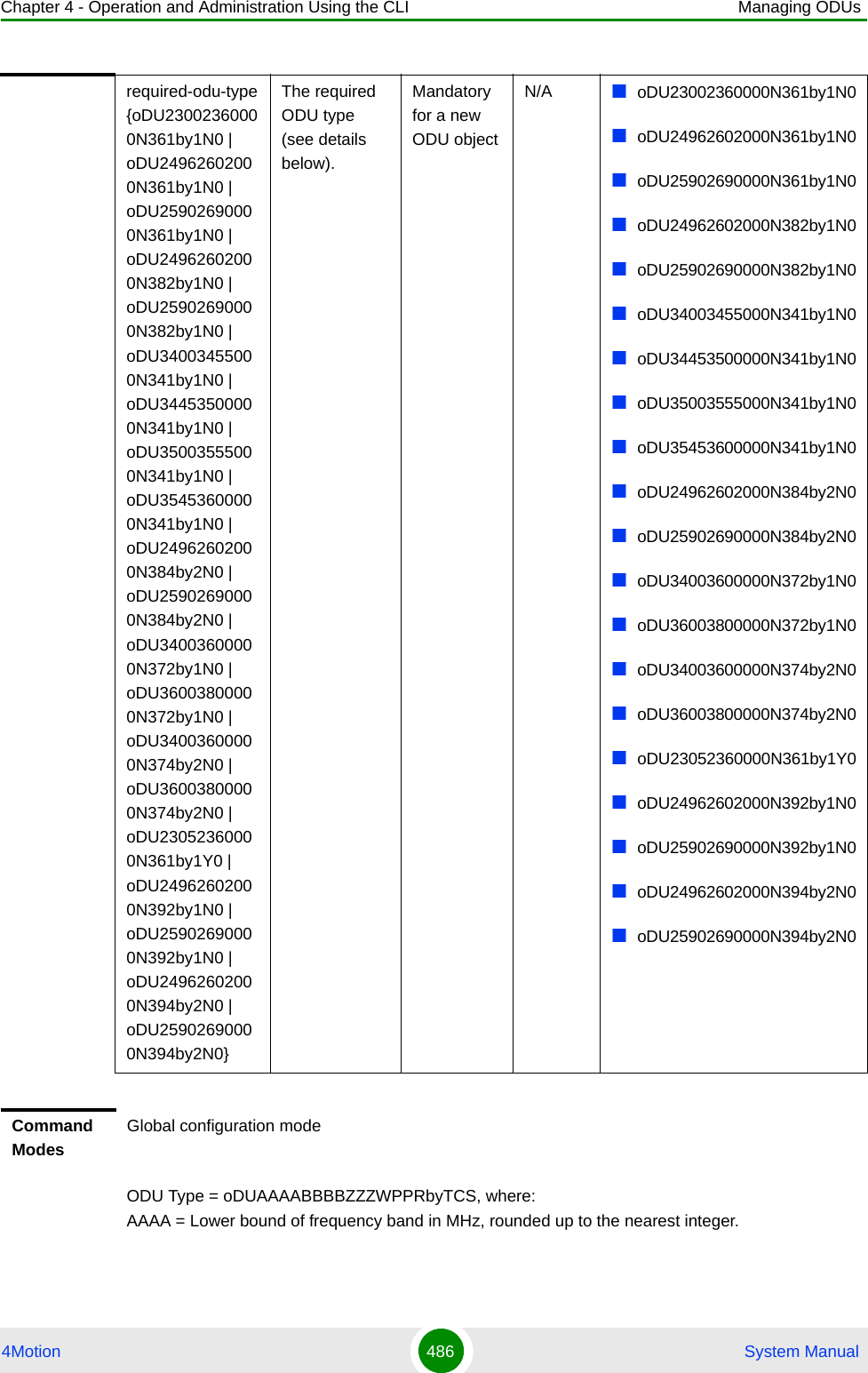
![Chapter 4 - Operation and Administration Using the CLI Managing ODUs4Motion 488 System ManualReserved (refer to Section 4.6.1.2.2)4.6.1.2.1 Configuring General ODU ParametersThe general table enables configuring the main properties of the required ODU.To configure the general ODU parameters, run the following command:npu(config-odu-params-1)# odu-general [heater-existence {TRUE | FALSE} ] [external-cavity-filter-existence {TRUE | FALSE} ] [required-odu-type {oDU23002360000N361by1N0 | oDU24962602000N361by1N0 | oDU25902690000N361by1N0 | oDU24962602000N382by1N0 | oDU25902690000N382by1N0 | oDU34003455000N341by1N0 | oDU34453500000N341by1N0 | oDU35003555000N341by1N0 | oDU35453600000N341by1N0 | oDU24962602000N384by2N0 | oDU25902690000N384by2N0 | oDU34003600000N372by1N0 | oDU36003800000N372by1N0 | oDU34003600000N374by2N0 | oDU36003800000N374by2N0 | oDU23052360000N361by1Y0 | oDU24962602000N392by1N0 | oDU25902690000N392by1N0 | oDU24962602000N394by2N0 | oDU25902690000N394by2N0} ]NOTEYou can display configuration information for the ODU general parameters. For details, refer to Section 4.6.1.6.1.IMPORTANTAn error may occur if you provide an invalid value for any of these parameters. Refer the syntax description for more information about the appropriate values and format for configuring these parameters.Command Syntaxnpu(config-odu-params-1)# odu-general [heater-existence {TRUE | FALSE} ] [external-cavity-filter-existence {TRUE | FALSE} ] [required-odu-type {oDU23002360000N361by1N0 | oDU24962602000N361by1N0 | oDU25902690000N361by1N0 | oDU24962602000N382by1N0 | oDU25902690000N382by1N0 | oDU34003455000N341by1N0 | oDU34453500000N341by1N0 | oDU35003555000N341by1N0 | oDU35453600000N341by1N0 | oDU24962602000N384by2N0 | oDU25902690000N384by2N0 | oDU34003600000N372by1N0 | oDU36003800000N372by1N0 | oDU34003600000N374by2N0 | oDU36003800000N374by2N0 | oDU23052360000N361by1Y0 | oDU24962602000N392by1N0 | oDU25902690000N392by1N0 | oDU24962602000N394by2N0 | oDU25902690000N394by2N0} ]](https://usermanual.wiki/Alvarion-Technologies/BMAX-OR-25.Manual-3/User-Guide-1114031-Page-7.png)
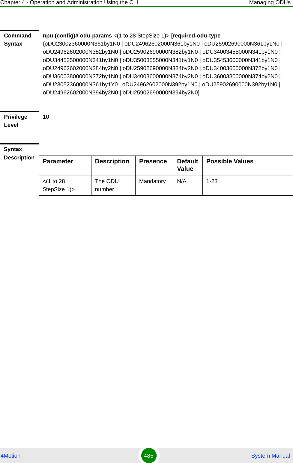
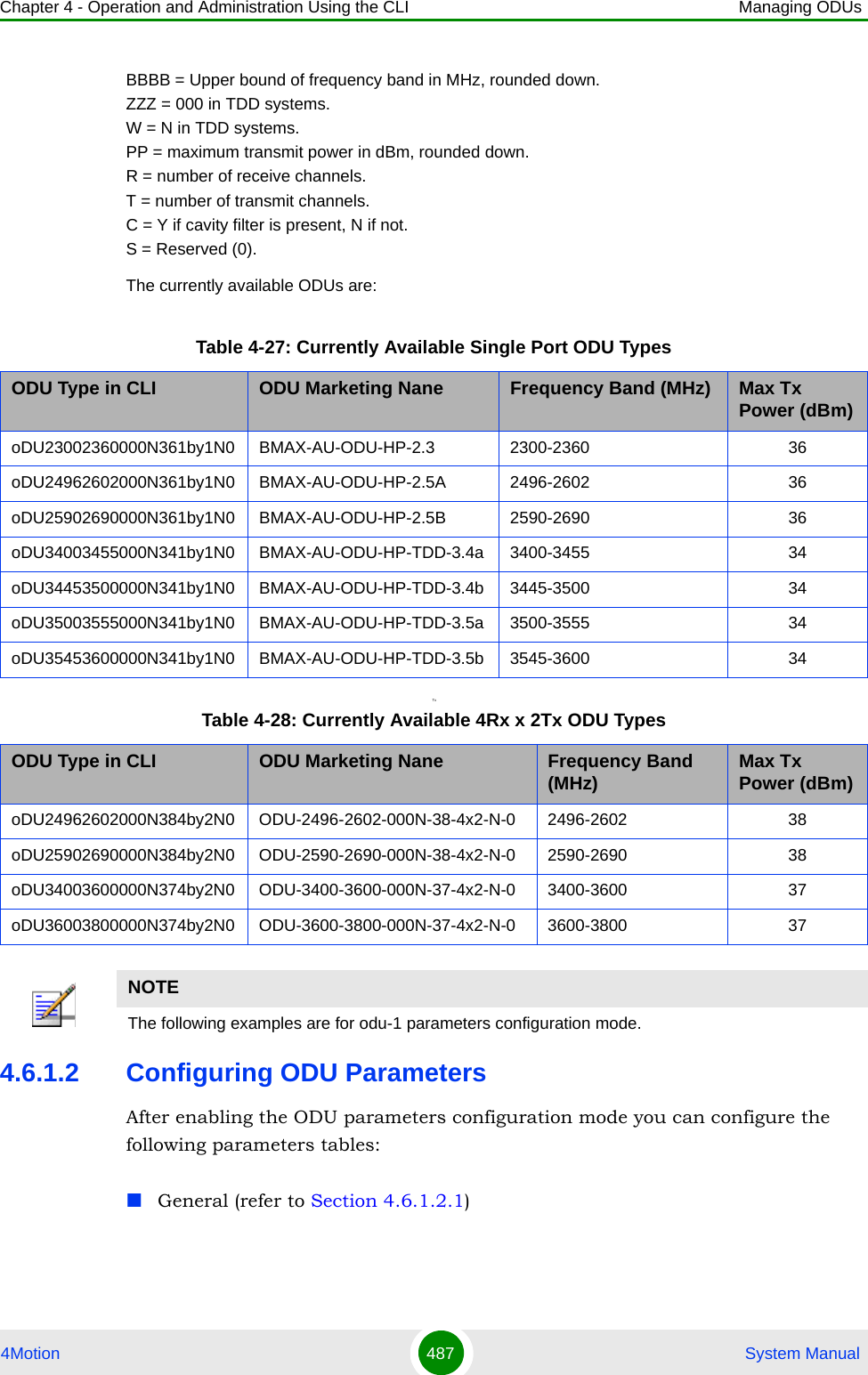
![Chapter 4 - Operation and Administration Using the CLI Managing ODUs4Motion 489 System Manual4.6.1.2.2 Configuring ODU Reserved ParametersAs the name implies, the reserved parameters table enables configuring up to 9 parameters that are reserved for possible future use. In the current release none of the reserved parameters is being used.To configure the ODU reserved parameters, run the following command:npu(config-odu-params-1)# odu-reserved [reserved-1 <string (32)>] [reserved-2 <string (32)>] [reserved-3 <string (32)>] [reserved-4 <string (32)>] [reserved-5 <string (32)>] [reserved-6 <string (32)>] [reserved-7 <string (32)>] [reserved-8 <string (32)>] [reserved-9 <string (32)>].Privilege Level10Syntax Description Parameter Description Presence Default Value Possible Values[heater-existence {TRUE | FALSE}]Informational parameter indicating whether a heater for the ODU exists. Optional FALSE TRUEFALSE[external-cavity-filter-existence {TRUE | FALSE}]Informational parameter indicating whether an external cavity filter for the ODU exists. Optional FALSE TRUEFALSE[required-odu-type {...} ]The required ODU type. For more details refer to Section 4.6.1.1Optional The previously configured valuwFor details refer to Section 4.6.1.1Command Modesodu-params configuration modeCommand Syntaxnpu (config-odu-params-1)# odu-reserved [reserved-1 <string (32)>] [reserved-2 <string (32)>] [reserved-3 <string (32)>] [reserved-4 <string (32)>] [reserved-5 <string (32)>] [reserved-6 <string (32)>] [reserved-7 <string (32)>] [reserved-8 <string (32)>] [reserved-9 <string (32)>]](https://usermanual.wiki/Alvarion-Technologies/BMAX-OR-25.Manual-3/User-Guide-1114031-Page-8.png)
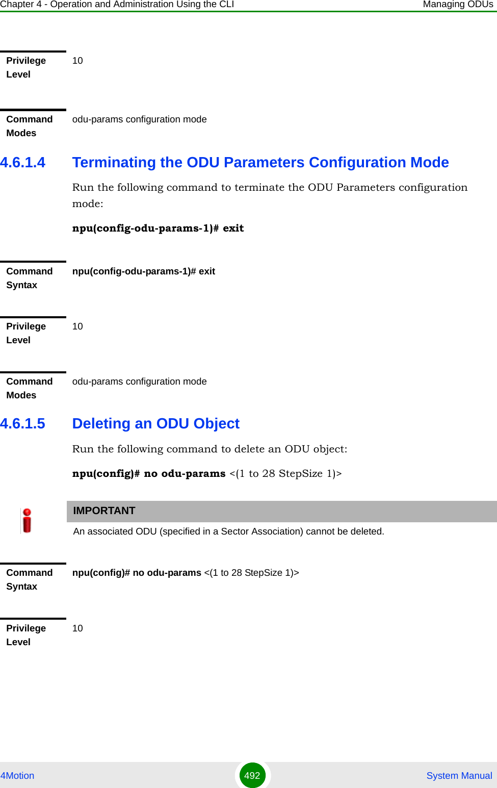
![Chapter 4 - Operation and Administration Using the CLI Managing ODUs4Motion 490 System Manual4.6.1.3 Restoring Default Values for ODU Configuration ParametersAfter enabling the ODU parameters configuration mode you can restore the default values for parameters in the following parameters tables:General (refer to Section 4.6.1.3.1)Reserved (refer to Section 4.6.1.3.2)4.6.1.3.1 Restoring the Default Values of General ParametersTo restore one or all of the general parameters to their default value (excluding the mandatory required-odu-type parameter), run the following command:npu(config-odu-params-1)# no odu-general [heater-existence] [external-cavity-filter-existence]You can restore only one parameter to its default value by specifying only that parameter. For example, to restore only the heater-existence to the default value (FALSE), run the following command:npu(config-odu-params-1)# no odu-general heater-existenceThe parameter will be restored to its default value, while the other parameters will remain unchanged.To restore all general parameters to their default value, run the following command:npu(config-odu-params-1)# no odu-generalPrivilege Level10Syntax Description Parameter Description Presence Default Value Possible Values[reserved-N <string (32)>] (N=1-9)Reserved parameter number NOptional null (an empty string)A string of 32 printable characters.Command Modesodu-params configuration mode](https://usermanual.wiki/Alvarion-Technologies/BMAX-OR-25.Manual-3/User-Guide-1114031-Page-9.png)
![Chapter 4 - Operation and Administration Using the CLI Managing ODUs4Motion 491 System Manual4.6.1.3.2 Restoring the Default Values of ODU Reserved ParametersTo restore the ODU Reserved parameters to their default value, run the following command:npu(config-odu-params-1)# no odu-reserved [reserved-1] [reserved-2] [reserved-3] [reserved-4] [reserved-5] [reserved-6] [reserved-7] [reserved-8] [reserved-9]You can restore only selected parameters to their default value by specifying only those parameter. For example, to restore only the reserved-1 parameter to its default values, run the following command:npu(config-odu-params-1)# no odu-reserved reserved-1This parameter will be restored to the default value, while the other parameters will remain unchanged.To restore all parameters to their default value, run the following command:npu(config-odu-params-1)# no odu-reservedNOTERefer to Section 4.6.1.2.1 for a description and default values of these parameters.Command Syntaxnpu(config-odu-params-1)# no odu-general [heater-existence] [external-cavity-filter-existence]Privilege Level10Command Modesodu-params configuration modeNOTERefer to Section 4.6.1.2.2 for a description and default values of these parameters.Command Syntaxnpu(config-odu-params-1)# no odu-reserved [reserved-1] [reserved-2] [reserved-3] [reserved-4] [reserved-5] [reserved-6] [reserved-7] [reserved-8] [reserved-9]](https://usermanual.wiki/Alvarion-Technologies/BMAX-OR-25.Manual-3/User-Guide-1114031-Page-10.png)
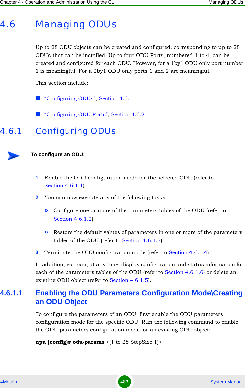
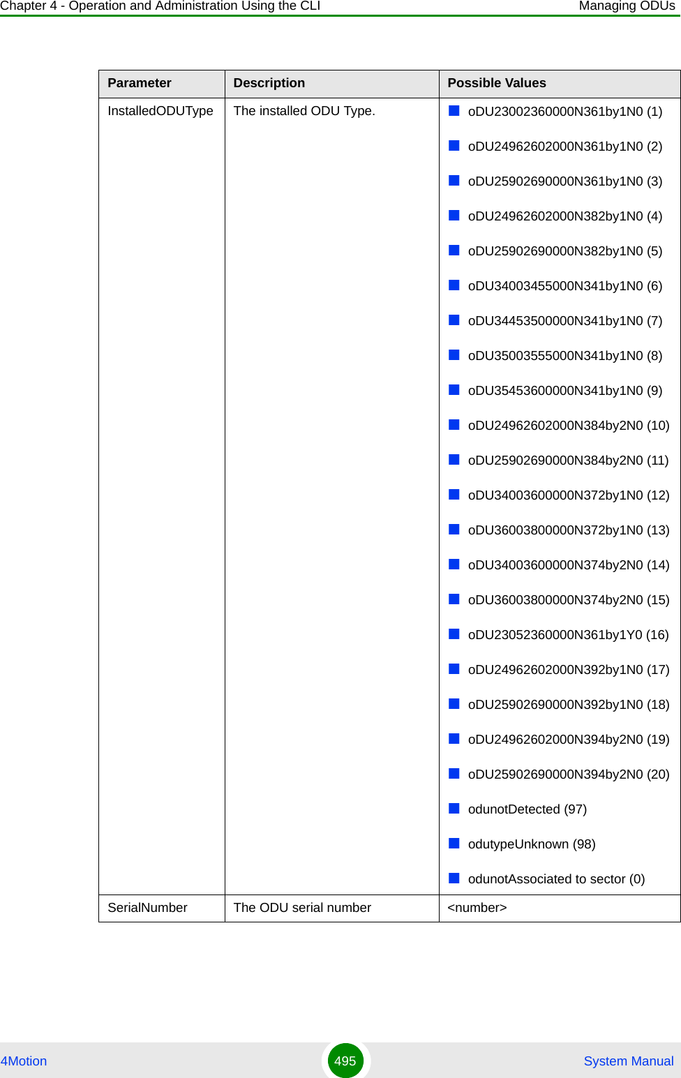
![Chapter 4 - Operation and Administration Using the CLI Managing ODUs4Motion 493 System Manual4.6.1.6 Displaying Configuration and Status Information for ODU ParametersYou can display the current configuration and (where applicable) additional status information for the following parameters tables:General (refer to Section 4.6.1.6.1)Reserved (refer to Section 4.6.1.6.2)4.6.1.6.1 Displaying Configuration and Status Information for ODU General ParametersTo display configuration and status information for the general parameters of a specific or all ODU objects, run the following command: npu# show odu-general [odu-no <(1 to 28 StepSize 1)>]Specify the ODU number (1-28) if you want to display configuration and status information for a particular ODU. Do not specify a value for this parameter if you want to view configuration and status information for all existing ODU objects.Syntax Description Parameter Description Presence Default ValuePossible Values <(1 to 28 StepSize 1)> The ODU number Mandatory N/A 1-28Command ModesGlobal configuration modeCommand Syntaxnpu# show odu-general [odu-no <(1 to 28 StepSize 1)> ]Privilege Level1](https://usermanual.wiki/Alvarion-Technologies/BMAX-OR-25.Manual-3/User-Guide-1114031-Page-12.png)
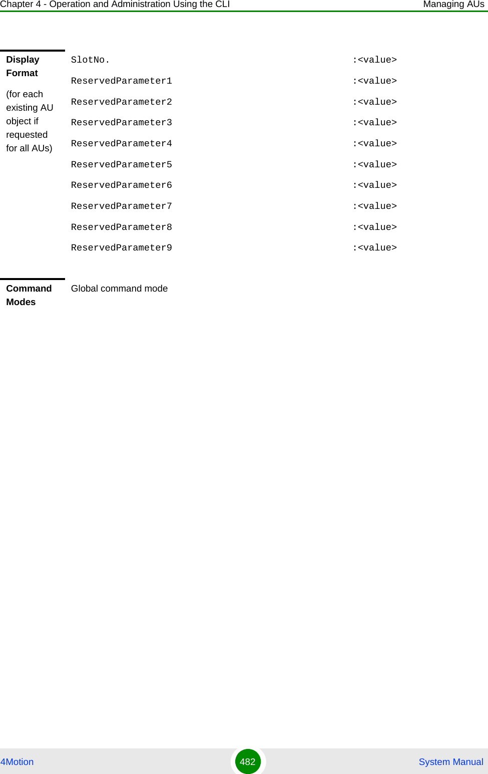
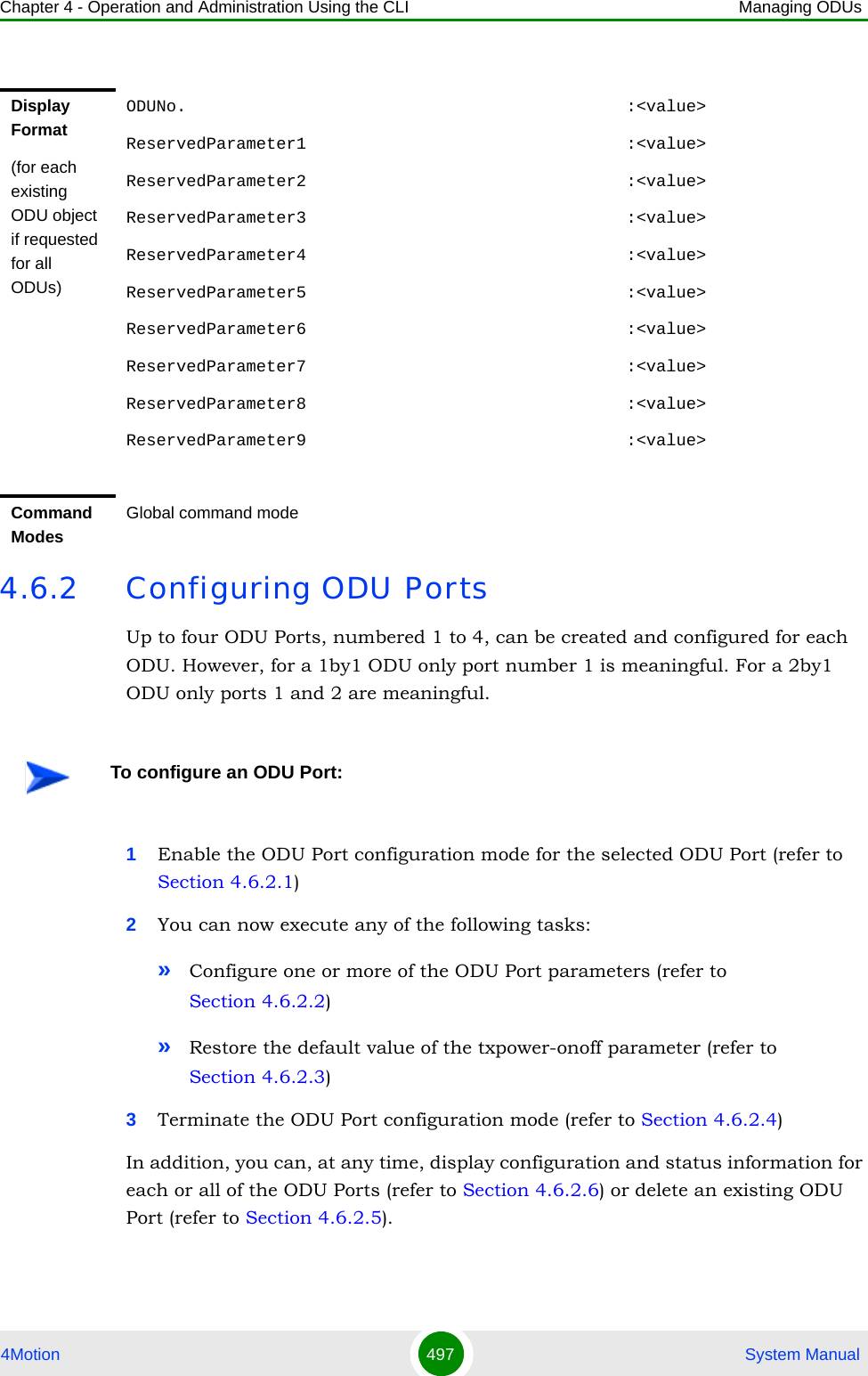
![Chapter 4 - Operation and Administration Using the CLI Managing ODUs4Motion 494 System ManualIn addition to the configurable parameters, the following status parameters are also displayed:Syntax Description Parameter Description Presence Default ValuePossible Values[odu-no <(1 to 28 StepSize 1)> ]The number of the ODU Specify a value for this parameter if you want to display the general parameters of a specific ODU. Do not specify a value for this parameter if you want to display the general parameters of all ODUs.Optional N/A 1-28Display Format(for each existing ODU object if requested for all ODUs)ODUNo. :<value>HeaterExistence :<value> or (0) if object does not existExternalCavityFilterExistence :<value> or (0) if object does not existRequiredODUType :<value> or (0) if object does not existInstalledODUType :<value> or (0) if ODU is not installedSerialNumber :<value> or null if ODU is not installedCommand ModesGlobal command mode](https://usermanual.wiki/Alvarion-Technologies/BMAX-OR-25.Manual-3/User-Guide-1114031-Page-13.png)
![Chapter 4 - Operation and Administration Using the CLI Managing ODUs4Motion 496 System Manual4.6.1.6.2 Displaying Configuration Information for ODU Reserved ParametersTo display configuration information for the reserved parameters of a specific or all ODU objects, run the following command: npu# show odu-reserved [odu-no <(1 to 28 StepSize 1)>]Specify the ODU number (1-28) if you want to display configuration for a particular ODU. Do not specify a value for this parameter if you want to view configuration for all existing ODU objects.Command Syntaxnpu# show odu-reserved [odu-no <(1 to 28 StepSize 1)> ]Privilege Level1Syntax Description Parameter Description Presence Default ValuePossible Values[odu-no <(1 to 28 StepSize 1)> ]The number of the ODU Specify a value for this parameter if you want to display the reserved parameters of a specific ODU. Do not specify a value for this parameter if you want to display the reserved parameters of all ODUs.Optional N/A 1-28](https://usermanual.wiki/Alvarion-Technologies/BMAX-OR-25.Manual-3/User-Guide-1114031-Page-15.png)
![Chapter 4 - Operation and Administration Using the CLI Managing ODUs4Motion 498 System Manual4.6.2.1 Enabling the ODU Port Configuration Mode\Creating an ODU PortTo configure the parameters of an ODU Port, first enable the ODU Port configuration mode for the specific ODU Port. Run the following command to enable the ODU Port configuration mode for an existing ODU Port:npu (config)# odu-port <(1 to 28 StepSize 1)> <(1 to 4 StepSize 1)>To create a new ODU Port, the mandatory txpower parameter must be specified. Run the following command to create a new ODU Port and enable the configuration mode for this ODU Port:npu (config)# odu-port <(1 to 28 StepSize 1)> <(1 to 4 StepSize 1)> txpower <(0 to 46 StepSize 0.1)>A new ODU Port is created with default values for the txpower-onoff parameter. For example, to create Port 1 in ODU 1 with a configured Tx Power of 34 dBm, and enable the parameters configuration mode for this ODU Port run the following command:npu (config)# odu-port 1 1 txpower 34After enabling the configuration mode for an ODU Port you can execute any of the following tasks:Configure one or more of the parameters of the ODU Port (refer to Section 4.6.2.2)Restore the default value of the txpower-onoff parameter (refer to Section 4.6.2.3)After executing the above tasks, you can terminate the ODU Port configuration mode (refer to Section 4.6.2.4) and return to the global configuration mode.Command Syntaxnpu (config)# odu-port <(1 to 28 StepSize 1)> <(1 to 4 StepSize 1)> [txpower <(0 to 46 StepSize 0.1)>]Privilege Level10](https://usermanual.wiki/Alvarion-Technologies/BMAX-OR-25.Manual-3/User-Guide-1114031-Page-17.png)
![Chapter 4 - Operation and Administration Using the CLI Managing ODUs4Motion 499 System Manual4.6.2.2 Configuring ODU Port ParametersAfter enabling the ODU Port configuration mode you can configure the transmit power parameters of the port.To configure the ODU Port parameters, run the following command:npu(config-odu-port-1-1)# params [txpower <(0 to 46 StepSize 0.1)> ] [txpower-onoff {on | off} ]Syntax Description Parameter Description Presence Default Value Possible Values<(1 to 28 StepSize 1)> The ODU number Mandatory N/A 1-28<(1 to 4 StepSize 1)> The Port number. Mandatory N/A 1-4[txpower <(0 to 46 StepSize 0.1)>]The required tx power at the specified ODU Port, in dBm.The actually available range depends on ODU Type: The upper limit is set by the Maximum Tx Power supported by the ODU (see “Currently Available Single Port ODU Types” on page 487). The control range for all ODUs is 10dBm, except to the following ODUs whose control range is 6dBm: oDU23002360000N361by1N0, oDU24962602000N361by1N0, oDU25902690000N361by1N0, oDU23052360000N361by1Y0Mandatory for a new ODU PortN/A 0 to 46 in increments of 0.1Command ModesGlobal configuration modeNOTEThe following examples are for odu-1, port-1 configuration mode.NOTEYou can display configuration information for the ODU Port parameters. For details, refer to Section 4.6.2.6.](https://usermanual.wiki/Alvarion-Technologies/BMAX-OR-25.Manual-3/User-Guide-1114031-Page-18.png)
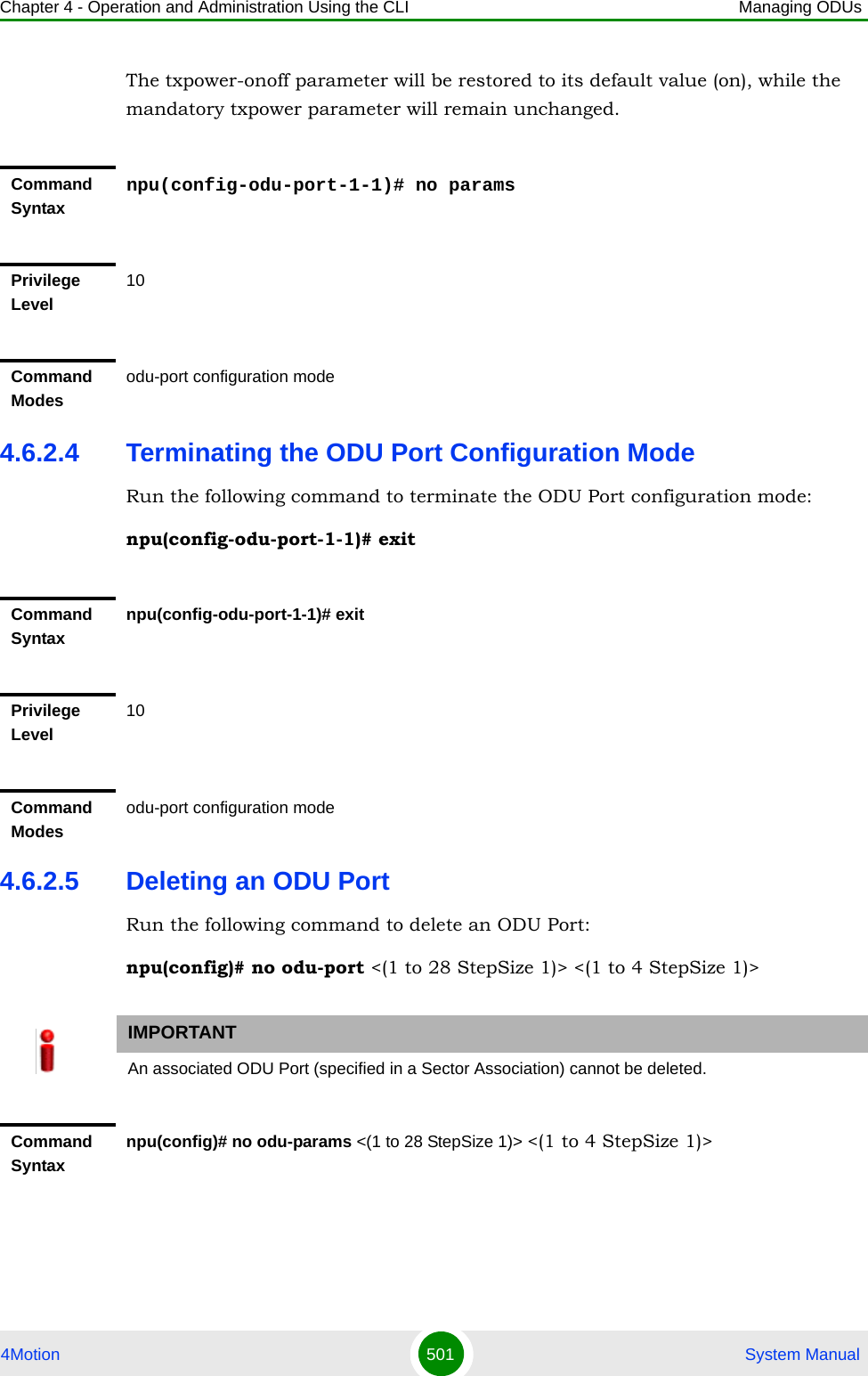
![Chapter 4 - Operation and Administration Using the CLI Managing ODUs4Motion 500 System Manual4.6.2.3 Restoring Default Values for ODU Port ParametersAfter enabling the ODU Port configuration mode you can restore the default values for the txpower-onoff parameter:To restore the default values for the txpower-onoff parameter, run the following command:npu(config-odu-port-1-1)# no paramsIMPORTANTAn error may occur if you provide an invalid value for any of these parameters. Refer the syntax description for more information about the appropriate values and format for configuring these parameters.Command Syntaxnpu(config-odu-port-1-1)# params [txpower <(0 to 46 StepSize 0.1)>] [txpower-onoff {on | off} ]Privilege Level10Syntax Description Parameter Description Presence Default Value Possible Values[txpower <(0 to 46 StepSize 0.1)>]The transmit power at the ODU Port, in dBm. Optional As configured previouslu0 to 46 in increments of 0.1Actual range depends on ODU type.[txpower-onoff {on | off} ]Enables or disables transmissions on this port. Optional on onoffCommand Modesodu-port configuration modeIMPORTANTAn error may occur if you provide an invalid value for any of these parameters. Refer the syntax description for more information about the appropriate values and format for configuring these parameters.](https://usermanual.wiki/Alvarion-Technologies/BMAX-OR-25.Manual-3/User-Guide-1114031-Page-19.png)
![Chapter 4 - Operation and Administration Using the CLI Managing ODUs4Motion 502 System Manual4.6.2.6 Displaying Configuration and Status Information for ODU PortsTo display configuration and status information of a specific or all ODU Ports, run the following command: npu# show odu-port [odu-no <(1 to 28 StepSize 1)> port-no <(1 to 4 StepSize 1)>]Specify the ODU number (1-28) and Port number (1-4) if you want to display configuration and status information for a particular ODU Port. Do not specify values for these parameters if you want to view configuration and status information for all existing ODU Ports.Privilege Level10Syntax Description Parameter Description Presence Default ValuePossible Values<(1 to 28 StepSize 1)> The ODU number Mandatory N/A 1-28<(1 to 4 StepSize 1)> The Port number Mandatory N/A 1-4Command ModesGlobal configuration modeCommand Syntaxnpu# show odu-port [odu-no <(1 to 28 StepSize 1)> port-no <(1 to 4 StepSize 1)> ]Privilege Level1](https://usermanual.wiki/Alvarion-Technologies/BMAX-OR-25.Manual-3/User-Guide-1114031-Page-21.png)
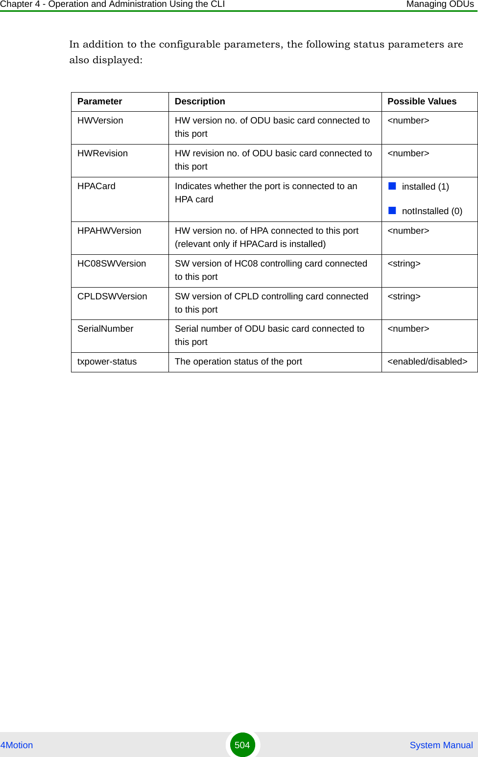
![Chapter 4 - Operation and Administration Using the CLI Managing ODUs4Motion 503 System ManualSyntax Description Parameter Description Presence Default ValuePossible Values[odu-no <(1 to 28 StepSize 1)> ]The number of the ODU Specify a value for this parameter if you want to display the parameters of a specific ODU Port. Do not specify a value for this parameter if you want to display the general parameters of all ODU Ports.Optional N/A 1-28[port-no <(1 to 4 StepSize 1)> ]The number of the Port Specify a value for this parameter if you want to display the parameters of a specific ODU Port. Do not specify a value for this parameter if you want to display the general parameters of all ODU Portss.Optional N/A 1-4Display Format(for each existing ODU Port if requested for all ODU Ports)ODUNo. :<value>ODUPortNo :<value>TxPower(dBm) :<value>TxEnable :<value>HWVersion :<value>HWRevision :<value>HPACard :<value>HPAHWVersion :<value>HC08SWVersion :<value>CPLDSWVersion :<value>SerialNumber :<value>txpower-status :<value>Command ModesGlobal command mode](https://usermanual.wiki/Alvarion-Technologies/BMAX-OR-25.Manual-3/User-Guide-1114031-Page-22.png)
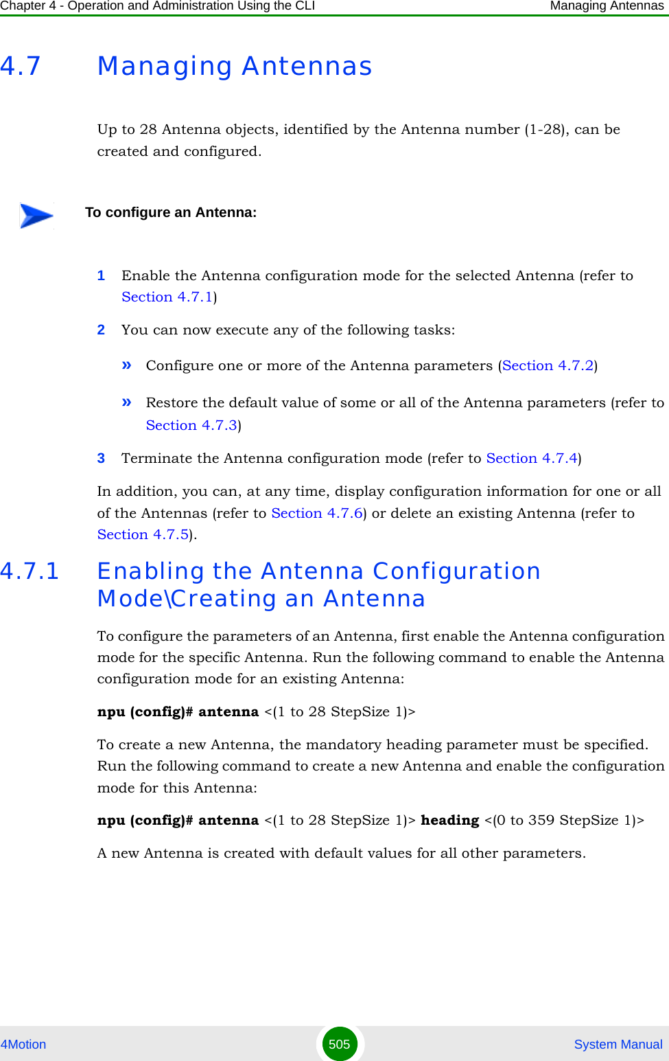
![Chapter 4 - Operation and Administration Using the CLI Managing Antennas4Motion 506 System ManualFor example, to create Antenna 1 with a configured heading of 90 degrees and enable the parameters configuration mode for this Antenna, run the following command:npu (config)# antenna 1 heading 90After enabling the configuration mode for an Antenna you can execute any of the following tasks:Configure one or more of the parameters of the Antenna (refer to Section 4.7.2)Restore the default value of the non-mandatory parameters parameter (refer to Section 4.7.3)After executing the above tasks, you can terminate the Antenna configuration mode (refer to Section 4.7.4) and return to the global configuration mode.IMPORTANTAn error may occur if you provide an invalid value for any of these parameters. Refer the syntax description for more information about the appropriate values and format for configuring these parameters.CAUTIONWhen an antenna is associated to a sector, the antenna heading must be the same as the sector heading for every antenna associated to the sector.Command Syntaxnpu (config)# antenna <(1 to 28 StepSize 1)> [heading <(0 to 359 StepSize 1)>]Privilege Level10Syntax Description Parameter Description Presence Default Value Possible Values<(1 to 28 StepSize 1)> The ODU number Mandatory N/A 1-28](https://usermanual.wiki/Alvarion-Technologies/BMAX-OR-25.Manual-3/User-Guide-1114031-Page-25.png)
![Chapter 4 - Operation and Administration Using the CLI Managing Antennas4Motion 507 System Manual4.7.2 Configuring Antenna ParametersAfter enabling the Antenna configuration mode you can configure the Antenna parameters.To configure the Antenna parameters, run the following command:npu(config-antenna-1)# params [antenna-type <string (32)>] [no-of-ports <(1 to 8 StepSize 1)>] [gain <(0 to 60 StepSize 0.1)>] [mechanical-downtilt <(-90 to 90 StepSize 0.1)>] [electrical-downtilt <(-90 to 90 StepSize 0.2)>] [electrical-azimuth-adjustment <(-90 to 90 StepSize 0.3)>] [longitude <longitude>] [latitude <latitude>] [tower-height <(0 to 500 StepSize 1)>] [altitude <(-500 to 10000 StepSize 1)>] [heading <(0 to 359 StepSize 1)>] [beamwidth <(0 to 359 StepSize 1)>] [cable-loss <(0 to 20 StepSize 0.1)>][heading <(0 to 359 StepSize 1)>]Indicates the azimuth angle (in degrees) between the center of the horizontal antenna beamwidth and the true north; counting clockwise.Mandatory for a new AntennaN/A 0 to 359Command ModesGlobal configuration modeNOTEThe following examples are for antenna-1 configuration mode.Command Syntaxnpu(config-antenna-1)# params [antenna-type <string (32)> ] [no-of-ports <(1 to 8 StepSize 1)> ] [gain <(0 to 60 StepSize 0.1)> ] [mechanical-downtilt <(-90 to 90 StepSize 0.1)> ] [electrical-downtil <(-90 to 90 StepSize 0.2)> ] [electrical-azimuth-adjustment <(-90 to 90 StepSize 0.3)> ] [longitude <longitude> ] [latitude <latitude> ] [tower-height <(0 to 500 StepSize 1)> ] [altitude <(-500 to 10000 StepSize 1)> ] [heading <(0 to 359 StepSize 1)> ] [beamwidth <(0 to 359 StepSize 1)> ] [cable-loss <(0 to 20 StepSize 0.1)> ]Privilege Level10](https://usermanual.wiki/Alvarion-Technologies/BMAX-OR-25.Manual-3/User-Guide-1114031-Page-26.png)
![Chapter 4 - Operation and Administration Using the CLI Managing Antennas4Motion 508 System ManualSyntax Description Parameter Description Presence Default Value Possible Values[antenna-type <string (32)> ]Antenna type to be populated manually for inventory information onlyOptional N/A String (up to 32 printable characters)[no-of-ports <(1 to 8 StepSize 1)> ]The number of antenna ports Optional 1 1-8[gain <(0 to 60 StepSize 0.1)> ]Antenna Gain (in dB) Optional 17 0-60 in steps of 0.1[mechanical-downtilt <(-90 to 90 StepSize 0.1)> ]Downwards mechanical tilt of the antenna (in degrees) as opposed to the electrical tilt already integrated in the antenna (and thus taken as reference; instead of the horizontal plane)Optional 0 -90.0 to 90.0in steps of 0.1[electrical-downtil <(-90 to 90 StepSize 0.1)> ]Downwards electrical tilt of the antenna, in degreesOptional 0 -90.0 to 90.0in steps of 0.1[electrical-azimuth-adjustment <(-90 to 90 StepSize 0.1)> ]Electrical azimuth adjustment of the antenna, in degrees (in a clockwise direction)Optional 0 -90.0 to 90.0in steps of 0.1[longitude <longitude> ]The longitude of the antenna.The recommended format is lll.mmm.a where lll.mmm is the longitude in degrees (lll - between 000 and 180, mmm - between 000 and 999), a is E (East) or W (West).Optional 000.000;EString[latitude <latitude> ]The latitude of the antenna. The recommended format is lll.mmm.a where lll.mmm is the longitude in degrees (lll - between 000 and 90, mmm - between 000 and 999), a is N (North) or S (South).Optional 000.000;EString[tower-height <(0 to 500 StepSize 1)> ]Defines the height of the antenna above the ground in meters.Optional 0 0-500](https://usermanual.wiki/Alvarion-Technologies/BMAX-OR-25.Manual-3/User-Guide-1114031-Page-27.png)
![Chapter 4 - Operation and Administration Using the CLI Managing Antennas4Motion 509 System Manual4.7.3 Restoring Default Values for Antenna ParametersAfter enabling the Antenna configuration mode you can restore the default values for some or all of the parameters (excluding the mandatory heading parameter).To restore one or several Antenna parameters do their default value, run the following command:npu(config-antenna-1)# no params [antenna-type] [no-of-ports] [gain] [mechanical-downtilt] [electrical-downtil] [electrical-azimuth-adjustment] [longitude] [latitude] [tower-height] [altitude] [beamwidth] [cable-loss][altitude <(-500 to 10000 StepSize 1)> ]Absolute altitude of the sector (above sea level) in meters.Optional -500 to 10000[heading <(0 to 359 StepSize 1)> ]Indicates the azimuth angle (in degrees) between the center of the horizontal antenna beamwidth and the true north; counting clockwise.Optional 0-359[beamwidth <(0 to 359 StepSize 1)> ]Beamwidth of the antenna in degreesOptional 60 0-359[cable-loss <(0 to 20 StepSize 0.1)> ]The attenuation (in dB) of the cable between the ODU port and antenna port (informative only)Optional 0.5 0-20 in steps of 0.1Command Modesantenna configuration modeNOTEYou can display configuration information for the Antenna parameters. For details, refer to Section 4.7.6.IMPORTANTAn error may occur if you provide an invalid value for any of these parameters. Refer the syntax description for more information about the appropriate values and format for configuring these parameters.](https://usermanual.wiki/Alvarion-Technologies/BMAX-OR-25.Manual-3/User-Guide-1114031-Page-28.png)
![Chapter 4 - Operation and Administration Using the CLI Managing Antennas4Motion 510 System ManualYou can restore one or several parameters to the default value(s) by specifying only those parameter. For example, to restore only the mechanical-downtilt and electrical-downtilt to their default values, run the following command:npu(config-antenna-1)# no params mechanical-downtilt electrical-downtilThe mechanical-downtilt and electrical-downtilt will be restored to their default values, while all other parameters will remain unchanged.To restore all parameters to their default value, run the following command:npu(config-antenna-1)# no params4.7.4 Terminating the Antenna Configuration ModeRun the following command to terminate the Antenna configuration mode:npu(config-antenna-1)# exitNOTERefer to Section 4.7.2 for a description and default values of these parameters.Command Syntaxnpu(config-antenna-1)# no params [antenna-type] [no-of-ports] [gain] [mechanical-downtilt] [electrical-downtil] [electrical-azimuth-adjustment] [longitude] [latitude] [tower-height] [altitude] [beamwidth] [cable-loss]Privilege Level10Command Modesantenna configuration mode Command Syntaxnpu(config-antenna-1)# exitPrivilege Level10](https://usermanual.wiki/Alvarion-Technologies/BMAX-OR-25.Manual-3/User-Guide-1114031-Page-29.png)
![Chapter 4 - Operation and Administration Using the CLI Managing Antennas4Motion 511 System Manual4.7.5 Deleting an AntennaRun the following command to delete an Antenna:npu(config)# no antenna <(1 to 28 StepSize 1)> 4.7.6 Displaying Configuration Information for AntennasTo display configuration information of a specific or all Antennas, run the following command: npu# show antenna [antenna-no <(1 to 28 StepSize 1)>]Specify the Antenna number (1-28) if you want to display configuration information for a particular Antenna. Do not specify values for this parameter if you want to view configuration information for all existing Antennas.Command Modesantenna configuration modeIMPORTANTAn associated Antenna (specified in a Sector Association) cannot be deleted.Command Syntaxnpu(config)# no antenna <(1 to 28 StepSize 1)> Privilege Level10Syntax Description Parameter Description Presence Default ValuePossible Values<(1 to 28 StepSize 1)> The Antenna number Mandatory N/A 1-28Command ModesGlobal configuration mode](https://usermanual.wiki/Alvarion-Technologies/BMAX-OR-25.Manual-3/User-Guide-1114031-Page-30.png)
![Chapter 4 - Operation and Administration Using the CLI Managing Antennas4Motion 512 System ManualCommand Syntaxnpu# show antenna [antenna-no <(1 to 28 StepSize 1)>]Privilege Level1Syntax Description Parameter Description Presence Default ValuePossible Values[antenna-no <(1 to 28 StepSize 1)> ]The number of the Antenna Specify a value for this parameter if you want to display the parameters of a specific Antenna. Do not specify a value for this parameter if you want to display the parameters of all Antennas.Optional N/A 1-28Display Format(for each existing Antenna if requested for all Antennas)AntennaNo. :<value>AntennaType :<value>No.ofPorts :<value>Gain(dB) :<value>MechanicalDownTilt(degrees) :<value>ElectricalDownTilt(degrees) :<value>ElectricalAzymuthAdjustment(degrees) :<value>Longtitude :<value>Latitude :<value>TowerHeight(meters) :<value>Altitude(meters) :<value>AntennaHeading(degrees) :<value>AntennaBeamWidth(degrees) :<value>CableLoss(dB) :<value>](https://usermanual.wiki/Alvarion-Technologies/BMAX-OR-25.Manual-3/User-Guide-1114031-Page-31.png)
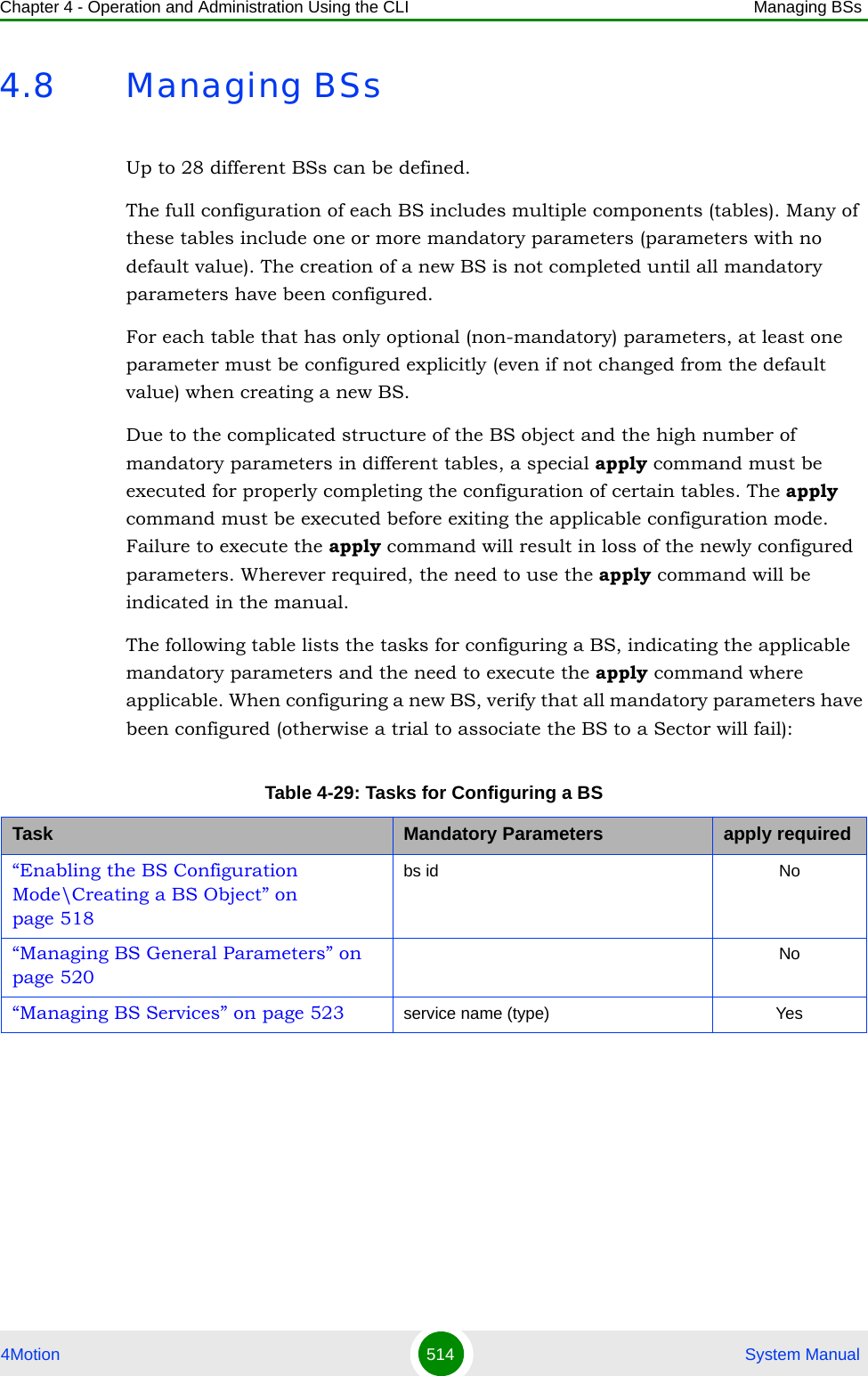
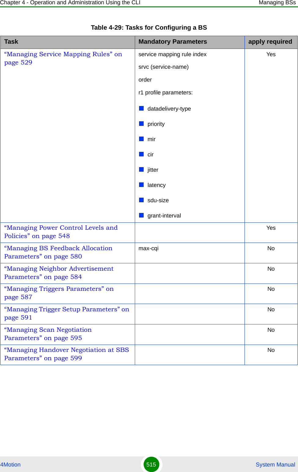
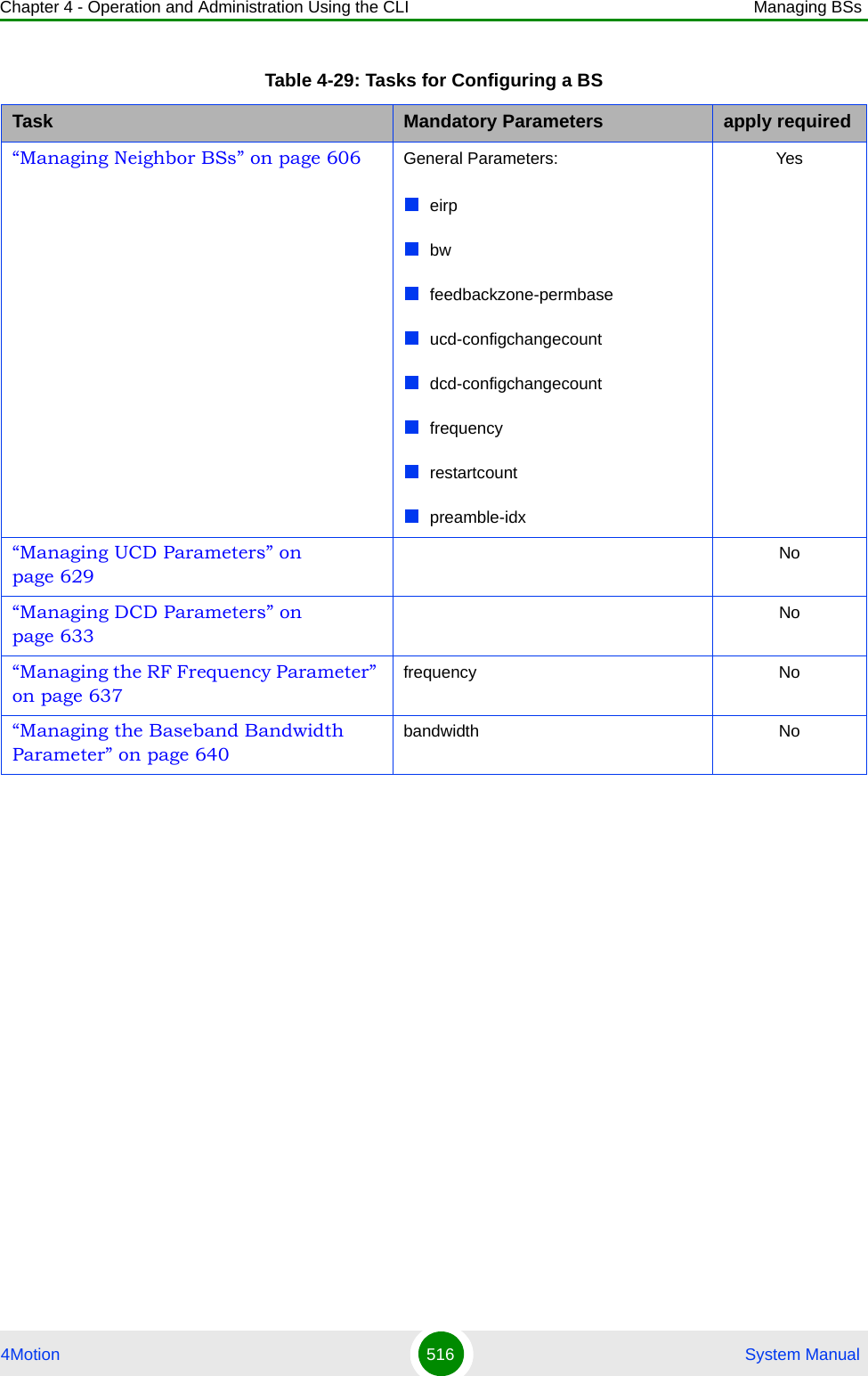
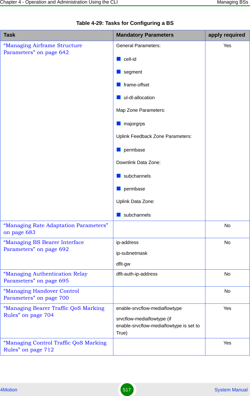
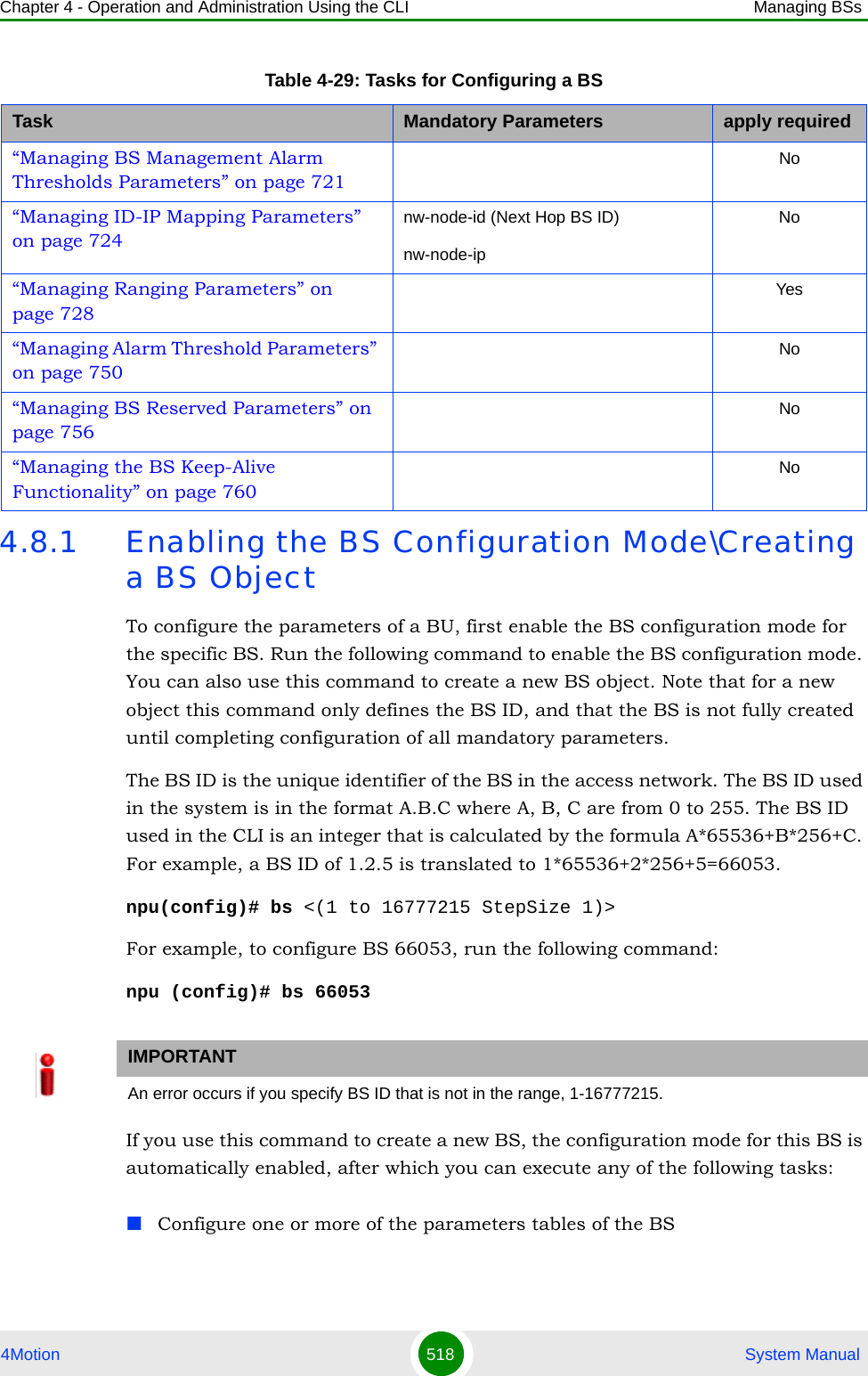
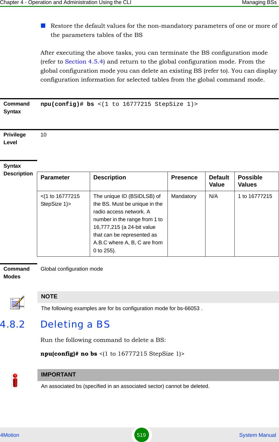
![Chapter 4 - Operation and Administration Using the CLI Managing BSs4Motion 520 System Manual4.8.3 Managing BS General ParametersThe general parameters of a BS include the Operator ID and the BS Name.After enabling the BS configuration mode, you can execute the following tasks:Configure one or more of the general parameters (refer to Section 4.8.3.1).Restore the default values of one or all of the general parameters (refer to Section 4.8.3.2).You can display configuration information for the general parameters of a selected or all existing BSs (refer to Section 4.8.3.3).4.8.3.1 Configuring BS General ParametersFrom the BS configuration mode, run the following command:npu(config-bs-66053)# general [operator-id <(1 to 16777215 StepSize 1)>] [bs-name <string (32)>]Command Syntaxnpu(config)# no bs <(1 to 16777215 StepSize 1)> Privilege Level10Syntax Description Parameter Description Presence Default ValuePossible Values<(1 to 16777215 StepSize 1)>The unique ID (BSIDLSB) of the BS. Mandatory N/A 1 to 16777215Command ModesGlobal configuration modeTo configure the BS General Parameters:](https://usermanual.wiki/Alvarion-Technologies/BMAX-OR-25.Manual-3/User-Guide-1114031-Page-39.png)
![Chapter 4 - Operation and Administration Using the CLI Managing BSs4Motion 521 System Manual4.8.3.2 Restoring Default Values for BS General ParametersAfter enabling the BS configuration mode you can restore the default values for one or all of the general BS parameters.To restore one or all general BS parameters do their default value, run the following command:npu(config-bs-66053)# no general [operator-id] [bs-name]You can restore one parameter to its default value by specifying only that parameter. For example, to restore only the operator-id to its default value, run the following command:IMPORTANTWhen creating a new BS, at least one of the BS General parameters must be configured explicitly (even if configured to the default value).Command Syntaxnpu(config-bs-66053)# general [operator-id <(1 to 16777215 StepSize 1)> ] [bs-name <string (32)> ]Privilege Level10Syntax Description Parameter Description Presence Default Value Possible Values[operator-id <(1 to 16777215 StepSize 1)>]A unique operator identifier. The same Operator ID must be used throughout the radio access network. (a 24-bit value that can be represented as A.B.C where A, B, C are from 0 to 255)Optional 16773929 1 to 16777215[bs-name <string (32)>] BS name Optional empty stringA string of up to 32 printable characters.Command Modesbs configuration mode](https://usermanual.wiki/Alvarion-Technologies/BMAX-OR-25.Manual-3/User-Guide-1114031-Page-40.png)
![Chapter 4 - Operation and Administration Using the CLI Managing BSs4Motion 522 System Manualnpu(config-bs-66053)# no general operator-idThe operator-id will be restored to its default value, while the bs-name parameter will remain unchanged.To restore all parameters to their default value, run the following command:npu(config-bs-66053)# no general4.8.3.3 Displaying Configuration Information for BS General ParametersTo display configuration information of the general parameters of a specific or all BSs, run the following command:npu# show general bs [<(1 to 16777215 StepSize 1)>]Specify the BS ID (1-16777215) of an existing BS if you want to display configuration information for a particular BS. Do not specify values for this parameter if you want to view configuration information for all existing BSs.NOTERefer to Section 4.8.3.1 for a description and default values of these parameters.Command Syntaxnpu(config-bs-66053)# no general [operator-id] [bs-name]Privilege Level10Command Modesbs configuration modeCommand Syntaxnpu# show general bs [<(1 to 16777215 StepSize 1)> ]Privilege Level1](https://usermanual.wiki/Alvarion-Technologies/BMAX-OR-25.Manual-3/User-Guide-1114031-Page-41.png)
![Chapter 4 - Operation and Administration Using the CLI Managing BSs4Motion 523 System Manual4.8.4 Managing BS ServicesThe BS Service parameters affect the properties of the HARQ mechanism for each Service.4.8.4.1 Enabling the BS Service Configuration Mode\Creating a BS ServiceTo configure the parameters of a BS Service, first enable the BS service configuration mode for the specific service. Run the following command to enable the BS service configuration mode. You can also use this command to create a new service with default values. npu(config-bs-66053)# service <(string (32))>For example, to define a new service named video, or to enable the configuration mode for an existing service named video, run the following command:npu(config-bs-66053)# service videoSyntax Description Parameter Description Presence Default ValuePossible Values[<(1 to 16777215 StepSize 1)> ]The BS ID Specify a value for this parameter if you want to display the general parameters of a specific BS. Do not specify a value for this parameter if you want to display the general parameters of all BSs.Optional N/A 1-16777215Display Format(for each existing BS if requested for all BSs)BSIDLSB :<value>OperatorID :<value>BSName :<value>Command ModesGlobal command mode](https://usermanual.wiki/Alvarion-Technologies/BMAX-OR-25.Manual-3/User-Guide-1114031-Page-42.png)
![Chapter 4 - Operation and Administration Using the CLI Managing BSs4Motion 524 System ManualIf you use this command to create a new service, the configuration mode for this service is automatically enabled, after which you can execute any of the following tasks:Configure the parameters of the service (refer to Section 4.8.4.2)Restore the default values for the non-mandatory parameters of the service (refer to Section 4.8.4.3)After executing the above tasks, you can terminate the BS Service configuration mode (refer to Section 4.8.4.4) and return to the BS configuration mode. From the BS configuration mode you can delete an existing service (refer to Section 4.8.4.5). You can display configuration information for BS services from the global command mode (refer to Section 4.8.4.6).Note that for properly completing the configuration of a service the apply command must be executed prior to exiting the BS Service configuration mode.4.8.4.2 Configuring Service ParametersFrom the BS configuration mode, run the following command:npu(config-bs-66053-service-video)# def [max-dl-rtx <(0 to 15 StepSize1)> ] [max-ul-rtx <(0 to 15 StepSize 1)> ] [max-subburst Command Syntaxnpu(config-bs-66053)# service <(string (32))>Privilege Level10Syntax Description Parameter Description Presence Default Value Possible Values<(string (32))> The Service name (type). Mandatory N/A A string of 1 to 32 characters.Command Modesbs configuration mode To configure the BS Service Parameters:](https://usermanual.wiki/Alvarion-Technologies/BMAX-OR-25.Manual-3/User-Guide-1114031-Page-43.png)
![Chapter 4 - Operation and Administration Using the CLI Managing BSs4Motion 525 System Manual<(0 to 1500 StepSize 1)> ] [trgt-err-rate <(0.1 to 10 StepSize 0.1)> ]4.8.4.3 Restoring Default Values for BS Service ParametersAfter enabling the BS Service configuration mode you can restore the default values for some or all of the non-mandatory parameters.IMPORTANTWhen creating a new Service, at least one of the Service parameters must be configured explicitly (even if configured to the default value).Command Syntaxnpu(config-bs-66053-service-video)# def [max-dl-rtx <(0 to 15 StepSize1)> ] [max-ul-rtx <(0 to 15 StepSize 1)> ] [max-subburst <(0 to 1500 StepSize 1)> ] [trgt-err-rate <(0.1 to 10 StepSize 0.1)> ]Privilege Level10Syntax Description Parameter Description Presence Default Value Possible Values[max-dl-rtx <(0 to 15 StepSize1)> ]The maximal number of downlink retransmissions of an HARQ sub-burst for this servicOptional 5 0 -15i[max-ul-rtx <(0 to 15 StepSize 1)> ]The maximal number of uplink retransmissions of an HARQ sub-burst for this serviceOptional 5 0 - 15[max-subburst <(0 to 1500 StepSize 1)> ]The maximal size of a sub-burst in bytes for this serviceOptional 600 0 - 1500[trgt-err-rate <(0.1 to 10 StepSize 0.1)>]The target sub-burst error rate for this serviceOptional 1 0.1 to 10 in steps of 0.1Command Modesbs service configuration mode](https://usermanual.wiki/Alvarion-Technologies/BMAX-OR-25.Manual-3/User-Guide-1114031-Page-44.png)
![Chapter 4 - Operation and Administration Using the CLI Managing BSs4Motion 526 System ManualTo restore one or several BS Service parameters do their default value, run the following command:npu(config-bs-66053-service-video)# no def [max-dl-rtx ] [max-ul-rtx ] [max-subburst ] [trgt-err-rate ]You can restore one or several parameters to the default value(s) by specifying only those parameter. For example, to restore only the max-dl-rtx and max-ul-rtx parameters to their default values, run the following command:npu(config-bs-66053-service-video)# no def max-dl-rtx max-ul-rtxThe max-dl-rtx and max-ul-rtx parameters will be restored to their default values, while all other parameters will remain unchanged.To restore all parameters to their default value, run the following command:npu(config-bs-66053-service-video)# no def4.8.4.4 Terminating the BS Service Configuration ModeRun the following command to terminate the BS Service configuration mode:npu(config-bs-66053-service-video)# exitNOTERefer to Section 4.8.4.2 for a description and default values of these parameters.Command Syntaxnpu(config-bs-66053-service-video)# no def [max-dl-rtx ] [max-ul-rtx ] [max-subburst ] [trgt-err-rate ]Privilege Level10Command Modesbs service configuration mode IMPORTANTDo not forget to execute the apply command before terminating the BS Service configuration mode:npu(config-bs-66053-service-video)# apply](https://usermanual.wiki/Alvarion-Technologies/BMAX-OR-25.Manual-3/User-Guide-1114031-Page-45.png)
![Chapter 4 - Operation and Administration Using the CLI Managing BSs4Motion 527 System Manual4.8.4.5 Deleting a BS ServiceRun the following command from the BS configuration mode to delete a BS Service:npu(config-bs 66053)# no service <string (32)> 4.8.4.6 Displaying Configuration Information for BS ServiceTo display configuration information of a specific or all BS Services, run the following command: npu# show service bs [<(1 to 16777215 StepSize 1)> service-name <string (32)>]Specify the BS ID and Service name if you want to display configuration information for a particular Service. Do not specify values for these parameter if you want to view configuration information for all existing BS Services.Command Syntaxnpu(config-bs-66053-service-video)# exitPrivilege Level10Command Modesbs service configuration modeCommand Syntaxnpu(config-bs 66053)# no service <string (32)> Privilege Level10Syntax Description Parameter Description Presence Default ValuePossible Values<string (32)> The Service name Mandatory N/A StringCommand Modesbs service configuration mode](https://usermanual.wiki/Alvarion-Technologies/BMAX-OR-25.Manual-3/User-Guide-1114031-Page-46.png)
![Chapter 4 - Operation and Administration Using the CLI Managing BSs4Motion 528 System ManualCommand Syntaxnpu# show service bs [<(1 to 16777215 StepSize 1)> service-name <string (32)>]Privilege Level1Syntax Description Parameter Description Presence Default ValuePossible Values<(1 to 16777215 StepSize 1)>The BS ID Specify a value for this parameter if you want to display the parameters of a specific BS Service. Do not specify a value for this parameter if you want to display the parameters of all BS Services.Optional N/A 1-16777215<string (32)> The Service name Specify a value for this parameter if you want to display the parameters of a specific BS Service. Do not specify a value for this parameter if you want to display the parameters of all BS Services.Optional N/A StringDisplay Format(for each existing Antenna if requested for all Antennas)BSIDLSB :<value>ServiceName :<value>MaximumDownlinkRetransmissions :<value>MaximumUplinkRetransmissions :<value>MaximumSub-BurstSize(bytes) :<value>TargetPacketErrorRate(%) :<value>Command ModesGlobal command mode](https://usermanual.wiki/Alvarion-Technologies/BMAX-OR-25.Manual-3/User-Guide-1114031-Page-47.png)
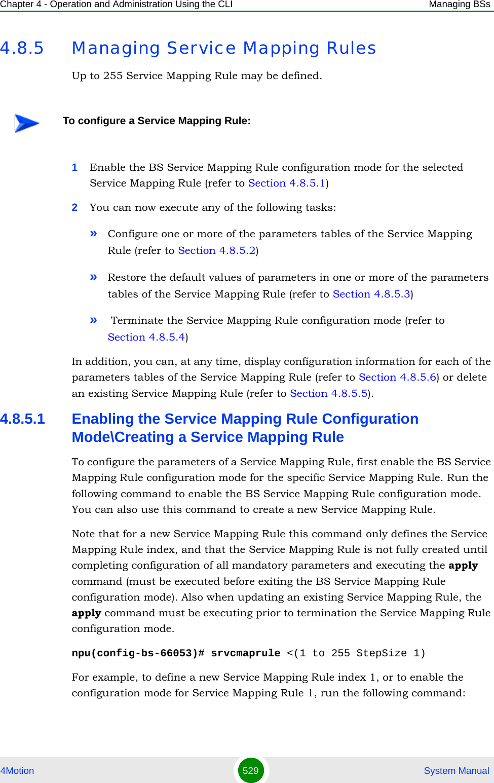
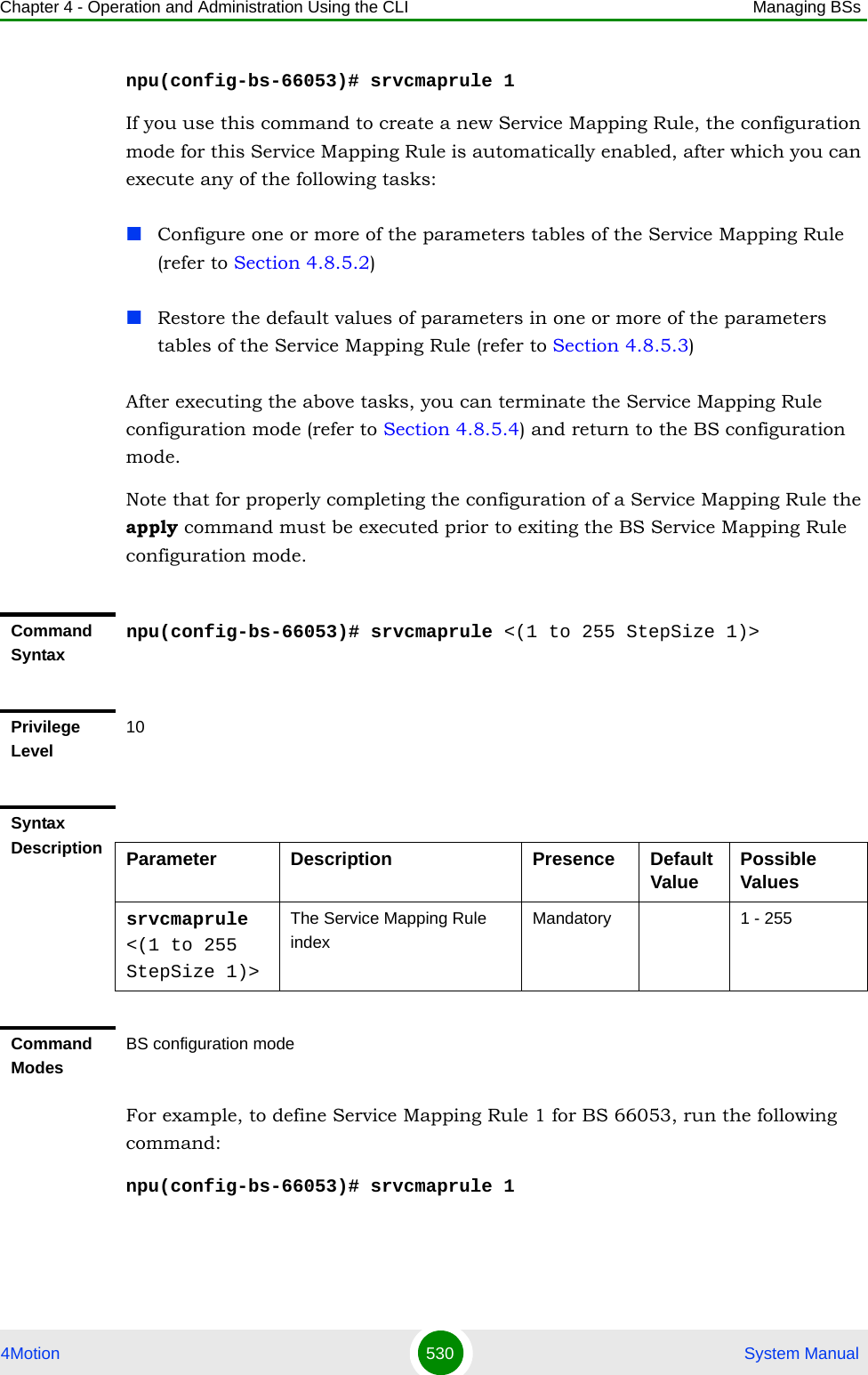
![Chapter 4 - Operation and Administration Using the CLI Managing BSs4Motion 532 System Manual4.8.5.2.2 Configuring the Order ParametersThe Order Parameters table enables configuring the look-up-order parameter that defines the order in which conceptual rows of the table are checked to find a match.To configure the Order parameters, run the following command:npu(config-bs-66053-srvcmaprule-1)# order look-up-order <(1 to 255 StepSize 1)>Syntax Description Parameter Description Presence Default Value Possible Values[srvc <string (32)> ] The service type to which the connection will be mapped.Must be the same as the name (type) configured for the relevant service (refer to Section 4.8.4).All service a certain data delivery type (see Section 4.8.5.2.3) must use the same service type (same HARQ properties).Mandatory A string of 1 to 32 printable characters.Command Modesbs service mapping rule configuration mode IMPORTANTWhen creating a new Service Mapping Rule, the mandaory order parameter must be configured.Command Syntaxnpu(config-bs-66053-srvcmaprule-1)# order [look-up-order <(1 to 255 StepSize 1)> ] Privilege Level10](https://usermanual.wiki/Alvarion-Technologies/BMAX-OR-25.Manual-3/User-Guide-1114031-Page-51.png)
![Chapter 4 - Operation and Administration Using the CLI Managing BSs4Motion 533 System Manual4.8.5.2.3 Configuring R1 Profile ParametersTo configure mapping rules to R1 Profile parameters, run the following command:npu(config-bs-66053-srvcmaprule-1)# r1prof [modify-serviceqos {TRUE | FALSE} ] [dfltpriority <(0 to 7 StepSize 1)> ] [datadeliverytype {uGS | rTVR | nRTVR | bE | eRTVR} ] [priority <(0 to 7 StepSize 1)> ] [mir <(0 to 20000 StepSize 1)> ] [cir <(0 to 20000 StepSize 1)> ] [jitter <(0 to 5000 StepSize 1)> ] [latency <(0 to 5000 StepSize 1)> ] [sdu-length {fixed | variable} ] [sdu-size <(1 to 255 StepSize 1)> ] [grant-interval <(0 to 5000 StepSize 1)> ]Syntax Description Parameter Description Presence Default Value Possible Values[look-up-order <(1 to 255 StepSize 1)> ]Defines the order in which the conceptual rows of the table are checked to find a match.Note: The value of this parameter must be different for each conceptual row instanceMandatory 1 to 255Command Modesbs service mapping rule configuration mode IMPORTANTWhen creating a new Service Mapping Rule, all mandatory parameters must be configured.Command Syntaxnpu(config-bs-66053-srvcmaprule-1)# r1prof [modify-serviceqos {TRUE | FALSE} ] [dfltpriority <(0 to 7 StepSize 1)> ] [datadeliverytype {uGS | rTVR | nRTVR | bE | eRTVR} ] [priority <(0 to 7 StepSize 1)> ] [mir <(0 to 20000 StepSize 1)> ] [cir <(0 to 20000 StepSize 1)> ] [jitter <(0 to 5000 StepSize 1)> ] [latency <(0 to 5000 StepSize 1)> ] [sdu-length{fixed | variable} ] [sdu-size <(1 to 255 StepSize 1)> ] [grant-interval <(0 to 5000 StepSize 1)> ]Privilege Level10](https://usermanual.wiki/Alvarion-Technologies/BMAX-OR-25.Manual-3/User-Guide-1114031-Page-52.png)
![Chapter 4 - Operation and Administration Using the CLI Managing BSs4Motion 534 System ManualSyntax Description Parameter Description Presence Default Value Possible Values[modify-serviceqos {TRUE | FALSE} ]Indicates whether to modify service QoS parameters using internal R1 profile parameters.Optional FALSE TRUEFALSE[dfltpriority <(0 to 7 StepSize 1)> ]Relevant only if modify-serviceqos is FALSE. Indicates the traffic priority to be used when it is missing in R6 request.Optional 0 0 to 7[datadeliverytype {uGS | rTVR | nRTVR | bE | eRTVR} ]Relevant only if modify-serviceqos is TRUE. An internal R1 profile parameter, specifying the type of data delivery (service type).(RTVR and NRTVR are not applicable for current release)Mandatory when creating a new Service Mapping Rule.N/A uGSrTVRnRTVRbEeRTVR[priority <(0 to 7 StepSize 1)> ]Relevant only if modify-serviceqos is TRUE and the datadeliverytype is rTVR, nRTVR, eRTVR or bE. An internal R1 profile parameter specifying the traffic priority.Mandatory when creating a new Service Mapping Rule.N/A 0 to 7[mir <(0 to 20000 StepSize 1)> ]Relevant only if modify-serviceqos is TRUE and the datadeliverytype is bE or eRTVR. An internal R1 profile parameter specifying the maximum sustained traffic rate in Kbps.Mandatory when creating a new Service Mapping Rule.N/A 0 - 20000[cir <(0 to 20000 StepSize 1)> ]Relevant only if modify-serviceqos is TRUE and the datadeliverytype is uGS or eRTVR. An internal R1 profile parameter specifying the minimum reserved traffic rate in Kbps.Mandatory when creating a new Service Mapping Rule.N/A 0 - 20000](https://usermanual.wiki/Alvarion-Technologies/BMAX-OR-25.Manual-3/User-Guide-1114031-Page-53.png)
![Chapter 4 - Operation and Administration Using the CLI Managing BSs4Motion 535 System Manual[jitter <(0 to 5000 StepSize 1)> ] Relevant only if modify-serviceqos is TRUE and the datadeliverytype is uGS or eRTVR. An internal R1 profile parameter specifying maximum tolerated jitter in milliseconds.Mandatory when creating a new Service Mapping Rule.N/A 0 - 5000[latency <(0 to 5000 StepSize 1)> ]Relevant only if modify-serviceqos is TRUE and the datadeliverytype is uGS or eRTVR. An internal R1 profile parameter specifying maximum latency in milliseconds.Mandatory when creating a new Service Mapping Rule.N/A 0 - 5000[sdu-length{fixed | variable} ]Relevant only if modify-serviceqos is TRUE and the datadeliverytype is uGS. An internal R1 profile parameter specifying whether SDU length is fixed or variable. In the current release only fixed length is supported.Optional fixed fixedvariable (not supported in current release)[sdu-size <(1 to 255 StepSize 1)> ]Relevant only if modify-serviceqos is TRUE, the datadeliverytype is uGS and the sdu-length is fixed. An internal R1 profile parameter specifying the SDU size in bytes.Mandatory when creating a new Service Mapping Rule.N/A 1 - 255[grant-interval <(0 to 5000 StepSize 1)> ] Relevant only if modify-serviceqos is TRUE and the datadeliverytype is uGS or eRTVR. An internal R1 profile parameter specifying the grant interval in milliseconds.Mandatory when creating a new Service Mapping Rule.N/A 0 - 5000Command Modesbs service mapping rule configuration mode](https://usermanual.wiki/Alvarion-Technologies/BMAX-OR-25.Manual-3/User-Guide-1114031-Page-54.png)
![Chapter 4 - Operation and Administration Using the CLI Managing BSs4Motion 536 System Manual4.8.5.2.4 Configuring R6 Profile ParametersTo configure mapping rules to R6 Profile parameters, run the following command:npu(config-bs-66053-srvcmaprule-1)# r6prof [datadeliverytype {uGS | rTVR | nRTVR | bE | eRTVR | any} ] [priority <(-1 to -1 StepSize 1) | (0 to 7 StepSize 1)> ] [mediaflowtype <string (32)> ] [use-mediaflowtype {TRUE | FALSE} ] [mir <(-1 to -1 StepSize 1) | (0 to 20000 StepSize 1)> ] [cir <(-1 to -1 StepSize 1) | (0 to 20000 StepSize 1)> ] [latency <(-1 to -1 StepSize 1) | (0 to 5000 StepSize 1)>].IMPORTANTNote that when creating a new Service Mapping Rule all mandatory parameters must be configured, including those that may not be relevant for the Service Mapping Rule.IMPORTANTWhen creating a new Service Mapping Rule, at least one of the R6 Profile parameters must be configured explicitly (even if configured to the default value).Command Syntaxnpu(config-bs-66053-srvcmaprule-2)# r6prof [datadeliverytype {uGS | rTVR | nRTVR | bE | eRTVR | any} ] [priority <(-1 to -1 StepSize 1) | (0 to 7 StepSize 1)> ] [mediaflowtype <string (32)> ] [use-mediaflowtype {TRUE | FALSE} ] [mir <(-1 to -1 StepSize 1) | (0 to 20000 StepSize 1)> ] [cir <(-1 to -1 StepSize 1) | (0 to 20000 StepSize 1)> ] [latency <(-1 to -1 StepSize 1) | (0 to 5000 StepSize 1)> ]Privilege Level10Syntax Description Parameter Description Presence Default Value Possible Values](https://usermanual.wiki/Alvarion-Technologies/BMAX-OR-25.Manual-3/User-Guide-1114031-Page-55.png)
![Chapter 4 - Operation and Administration Using the CLI Managing BSs4Motion 537 System Manual[datadeliverytype {uGS | rTVR | nRTVR | bE | eRTVR | any} ]An R6 parameter entry in the lookup table specifying the data delivery type (service type).Optional any uGSrTVRnRTVRbEeRTVRany[priority <(-1 to -1 StepSize 1) | (0 to 7 StepSize 1)> ]An R6 parameter entry in the lookup table specifying the traffic priority. A value of -1 means any.Optional -1 -10 - 7[mediaflowtype <string (32)> ]An R6 parameter entry in the lookup table that is relevant only if the use-mediaflowtype parameter is defined as TRUEOptional blank string A string of 32 printable characters.[use-mediaflowtype {TRUE | FALSE} ]If this parameter has a value TRUE, the service lookup function will try to match the R6 media flow type with the mediaFlowType entry in the table. If FALSE the service lookup function will ignore the R6 media flow type.Optional FALSE TRUEFALSE[mir <(-1 to -1 StepSize 1) | (0 to 20000 StepSize 1)> ]An R6 parameter entry in the lookup table specifyingthe maximum sustained traffic rate in Kbps. A value of -1 means any.Optional -1 -10 - 20000[cir <(-1 to -1 StepSize 1) | (0 to 20000 StepSize 1)> ]An R6 parameter entry in the lookup table specifying the minimum reserved traffic rate in Kbps. A value of -1 means any.Optional -1 -10 - 20000[latency <(-1 to -1 StepSize 1) | (0 to 5000 StepSize 1)> ]An R6 parameter entry in the lookup table specifying tolerated latency in milliseconds. A value of -1 means any.Optional -1 -10 - 5000](https://usermanual.wiki/Alvarion-Technologies/BMAX-OR-25.Manual-3/User-Guide-1114031-Page-56.png)
![Chapter 4 - Operation and Administration Using the CLI Managing BSs4Motion 538 System Manual4.8.5.3 Restoring Default Values for Service Mapping Rule Configuration ParametersAfter enabling the Service Mapping Rule configuration mode you can restore the default values for non-mandatory parameters in the following parameters tables:R1 Profile (refer to Section 4.8.5.3.1)R6 Profile (refer to Section 4.8.5.3.2)4.8.5.3.1 Restoring the Default Values of RI Profile ParametersTo restore some or all of R1 Profile non-mandatory parameters to their default values, run the following command:npu(config-bs-66053-srvcmaprule-1)# no r1prof [modify-serviceqos ] [dfltpriority ]You can restore only one or several parameters to the default values by specifying only those parameters. For example, to restore only the dfltpriority to the default value, run the following command:npu(config-bs-66053-srvcmaprule-1)# no r1prof dfltpriorityThe parameter will be restored to its default value, while the other parameters will remain unchanged.To restore all R1 Profile non-mandatory parameters to their default value, run the following command:npu(config-bs-66053-srvcmaprule-1)# no r1profCommand Modesbs service mapping rule configuration modeNOTERefer to Section 4.8.5.2.3 for a description and default values of these parameters.Command Syntaxnpu(config-bs-66053-srvcmaprule-1)# no r1prof [modify-serviceqos ] [dfltpriority ]Privilege Level10](https://usermanual.wiki/Alvarion-Technologies/BMAX-OR-25.Manual-3/User-Guide-1114031-Page-57.png)
![Chapter 4 - Operation and Administration Using the CLI Managing BSs4Motion 539 System Manual4.8.5.3.2 Restoring the Default Values of R6 Profile ParametersTo restore some or all of R6 Profile parameters to their default values, run the following command:npu(config-bs-66053-srvcmaprule-1)# no r6prof [datadeliverytype ] [priority ] [mediaflowtype ] [use-mediaflowtype] [mir ] [cir ] [latency ]You can restore only one or several parameters to the default values by specifying only those parameters. For example, to restore only the mir and cir to the default values, run the following command:npu(config-bs-66053-srvcmaprule-1)# no r6prof mir cirThese parameter will be restored to their default values, while all other parameters will remain unchanged.To restore all R6 Profile parameters to their default value, run the following command:npu(config-bs-66053-srvcmaprule-1)# no r6prof4.8.5.4 Terminating the Service Mapping Rule Configuration ModeRun the following command to terminate the Service Mapping Rule configuration mode:Command Modesbs service mapping rule configuration modeNOTERefer to Section 4.8.5.2.4 for a description and default values of these parameters.Command Syntaxnpu(config-bs-66053-srvcmaprule-1)# no r6prof [datadeliverytype ] [priority ] [mediaflowtype ] [use-mediaflowtype] [mir ] [cir ] [latency ]Privilege Level10Command Modesbs service mapping rule configuration mode](https://usermanual.wiki/Alvarion-Technologies/BMAX-OR-25.Manual-3/User-Guide-1114031-Page-58.png)
![Chapter 4 - Operation and Administration Using the CLI Managing BSs4Motion 541 System Manual4.8.5.6 Displaying Configuration Information for Service Mapping RulesYou can display the current configuration information for the following parameters tables:General (refer to Section 4.8.5.6.1)Order (refer to Section 4.8.5.6.2)R1 Profile (refer to Section 4.8.5.6.3)R6 Profile (refer to Section 4.8.5.6.4)All (refer to Section 4.8.5.6.5)4.8.5.6.1 Displaying Configuration Information for General Service Mapping Rule ParametersTo display configuration for the general parameters of a specific or all Service Mapping Rules, run the following command:npu# show srvcmaprule-general bs [<(1 to 16777215 StepSize 1)> rule-index <(1 to 255 StepSize 1)>]Specify the BS ID and Service Mapping Rule index if you want to display configuration for a particular Service Mapping Rule. For example, to display the General parameters of Service Mapping Rule 1 in BS 66053, run the following command:npu# show srvcmaprule-general bs 66053 rule-index 1Do not specify these parameters if you want to view configuration information for all existing Service Mapping Rules. To display information for all Service Mapping Rules, run the following command:npu# show srvcmaprule-general bsCommand Syntaxnpu# show srvcmaprule-general bs [<(1 to 16777215 StepSize 1)> rule-index <(1 to 255 StepSize 1)> ]Privilege Level1](https://usermanual.wiki/Alvarion-Technologies/BMAX-OR-25.Manual-3/User-Guide-1114031-Page-60.png)
![Chapter 4 - Operation and Administration Using the CLI Managing BSs4Motion 542 System Manual4.8.5.6.2 Displaying Configuration Information for Service Mapping Rule Order ParametersTo display configuration for the order parameters of a specific or all Service Mapping Rules, run the following command:npu# show srvcmaprule-order bs [<(1 to 16777215 StepSize 1)> rule-index <(1 to 255 StepSize 1)>]Syntax Description Parameter Description Presence Default ValuePossible Values<(1 to 16777215 StepSize 1)>The BS ID Specify a value for this parameter if you want to display the general parameters of a specific Service Mapping Rule. Do not specify a value for this parameter if you want to display the general parameters of all Service Mapping Rules.Optional N/A 1-16777215rule-index <(1 to 255 StepSize 1)> ]The Service Mapping Rule index. To be used only if you want to display the general parameters of a specific Service Mapping Rule.Optional N/A 1-255Display Format(for each existing Service Mapping Rule if requested for all Service Mapping Rules)BSIDLSB :<value>MappingRuleIndex :<value>ServiceName :<value>Command ModesGlobal command mode](https://usermanual.wiki/Alvarion-Technologies/BMAX-OR-25.Manual-3/User-Guide-1114031-Page-61.png)
![Chapter 4 - Operation and Administration Using the CLI Managing BSs4Motion 543 System ManualSpecify the BS ID and Service Mapping Rule index if you want to display configuration for a particular Service Mapping Rule. For example, to display the order parameters of Service Mapping Rule 1 in BS 66053, run the following command:npu# show srvcmaprule-order bs 66053 rule-index 1Do not specify these parameters if you want to view configuration information for all existing Service Mapping Rules. To display information for all Service Mapping Rules, run the following command:npu# show srvcmaprule-order bsCommand Syntaxnpu# show srvcmaprule-order bs [<(1 to 16777215 StepSize 1)> rule-index <(1 to 255 StepSize 1)> ]Privilege Level1Syntax Description Parameter Description Presence Default ValuePossible Values<(1 to 16777215 StepSize 1)>The BS ID Specify a value for this parameter if you want to display the order parameters of a specific Service Mapping Rule. Do not specify a value for this parameter if you want to display the order parameters of all Service Mapping Rules.Optional N/A 1-16777215rule-index <(1 to 255 StepSize 1)>]The Service Mapping Rule index. To be used only if you want to display the order parameters of a specific Service Mapping Rule.Optional N/A 1-255](https://usermanual.wiki/Alvarion-Technologies/BMAX-OR-25.Manual-3/User-Guide-1114031-Page-62.png)
![Chapter 4 - Operation and Administration Using the CLI Managing BSs4Motion 544 System Manual4.8.5.6.3 Displaying Configuration Information for Service Mapping Rule R1 Profile ParametersTo display configuration for the R1 Profile parameters of a specific or all Service Mapping Rules, run the following command:npu# show srvcmaprule-r1prof bs [<(1 to 16777215 StepSize 1)> rule-index <(1 to 255 StepSize 1)>]Specify the BS ID and Service Mapping Rule index if you want to display configuration for a particular Service Mapping Rule. For example, to display the R1 Profile parameters of Service Mapping Rule 1 in BS 66053, run the following command:npu# show srvcmaprule-r1prof bs 66053 rule-index 1Do not specify these parameters if you want to view configuration information for all existing Service Mapping Rules. To display information for all Service Mapping Rules, run the following command:npu# show srvcmaprule-r1prof bsDisplay Format(for each existing Service Mapping Rule if requested for all Service Mapping Rules)BSIDLSB :<value>MappingRuleIndex :<value>LookUpOrder :<value>Command ModesGlobal command modeCommand Syntaxnpu# show srvcmaprule-r1prof bs [<(1 to 16777215 StepSize 1)> rule-index <(1 to 255 StepSize 1)> ]Privilege Level1](https://usermanual.wiki/Alvarion-Technologies/BMAX-OR-25.Manual-3/User-Guide-1114031-Page-63.png)
![Chapter 4 - Operation and Administration Using the CLI Managing BSs4Motion 545 System ManualSyntax Description Parameter Description Presence Default ValuePossible Values<(1 to 16777215 StepSize 1)>The BS ID Specify a value for this parameter if you want to display the R1 Profile parameters of a specific Service Mapping Rule. Do not specify a value for this parameter if you want to display the R1 Profile parameters of all Service Mapping Rules.Optional N/A 1-16777215rule-index <(1 to 255 StepSize 1)>]The Service Mapping Rule index. To be used only if you want to display the R1 Profile parameters of a specific Service Mapping Rule.Optional N/A 1-255Display Format(for each existing Service Mapping Rule if requested for all Service Mapping Rules)BSIDLSB :<value>MappingRuleIndex :<value>ModifyServiceQoSParameters :<value>DefaultPriority :<value>DataDeliveryTypeR1Profile :<value>PriorityR1Profile :<value>MIRR1Profile :<value>CIRR1Profile :<value>Jitter :<value>LatencyR1Profile :<value>SDULength :<value>SDUSize :<value>Command ModesGlobal command mode](https://usermanual.wiki/Alvarion-Technologies/BMAX-OR-25.Manual-3/User-Guide-1114031-Page-64.png)
![Chapter 4 - Operation and Administration Using the CLI Managing BSs4Motion 546 System Manual4.8.5.6.4 Displaying Configuration Information for Service Mapping Rule R6 Profile ParametersTo display configuration for the R6 Profile parameters of a specific or all Service Mapping Rules, run the following command:npu# show srvcmaprule-r6prof bs [<(1 to 16777215 StepSize 1)> rule-index <(1 to 255 StepSize 1)>]Specify the BS ID and Service Mapping Rule index if you want to display configuration for a particular Service Mapping Rule. For example, to display the R6 Profile parameters of Service Mapping Rule 1 in BS 66053, run the following command:npu# show srvcmaprule-r6prof bs 66053 rule-index 1Do not specify these parameters if you want to view configuration information for all existing Service Mapping Rules. To display information for all Service Mapping Rules, run the following command:npu# show srvcmaprule-r6prof bsCommand Syntaxnpu# show srvcmaprule-r6prof bs [<(1 to 16777215 StepSize 1)> rule-index <(1 to 255 StepSize 1)> ]Privilege Level1Syntax Description Parameter Description Presence Default ValuePossible Values<(1 to 16777215 StepSize 1)>The BS ID Specify a value for this parameter if you want to display the R6 Profile parameters of a specific Service Mapping Rule. Do not specify a value for this parameter if you want to display the general parameters of all Service Mapping Rules.Optional N/A 1-16777215](https://usermanual.wiki/Alvarion-Technologies/BMAX-OR-25.Manual-3/User-Guide-1114031-Page-65.png)
![Chapter 4 - Operation and Administration Using the CLI Managing BSs4Motion 547 System Manual4.8.5.6.5 Displaying Configuration Information for All Service Mapping Profile ParametersTo display all configuration parameters of a specific or all Service Mapping Rules, run the following command:npu# show srvcmaprule-all bs [<(1 to 16777215 StepSize 1)> rule-index <(1 to 255 StepSize 1)>]Specify the BS ID and Service Mapping Rule index if you want to display configuration for a particular Service Mapping Rule. For example, to display all parameters of Service Mapping Rule 1 in BS 66053, run the following command:npu# show srvcmaprule-all bs 66053 rule-index 1Do not specify these parameters if you want to view configuration information for all existing Service Mapping Rules. To display information for all Service Mapping Rules, run the following command:npu# show srvcmaprule-all bsrule-index <(1 to 255 StepSize 1)>]The Service Mapping Rule index. To be used only if you want to display the R6 Profile parameters of a specific Service Mapping Rule.Optional N/A 1-255Display Format(for each existing Service Mapping Rule if requested for all Service Mapping Rules)BSIDLSB :<value>MappingRuleIndex :<value>DataDeliveryTypeR6Profile :<value>PriorityR6Profile :<value>MediaFlowType :<value>UseMediaFlowType :<value>CIRR6Profile :<value>MIRR6Profile :<value>LatencyR6Profile :<value>Command ModesGlobal command mode](https://usermanual.wiki/Alvarion-Technologies/BMAX-OR-25.Manual-3/User-Guide-1114031-Page-66.png)
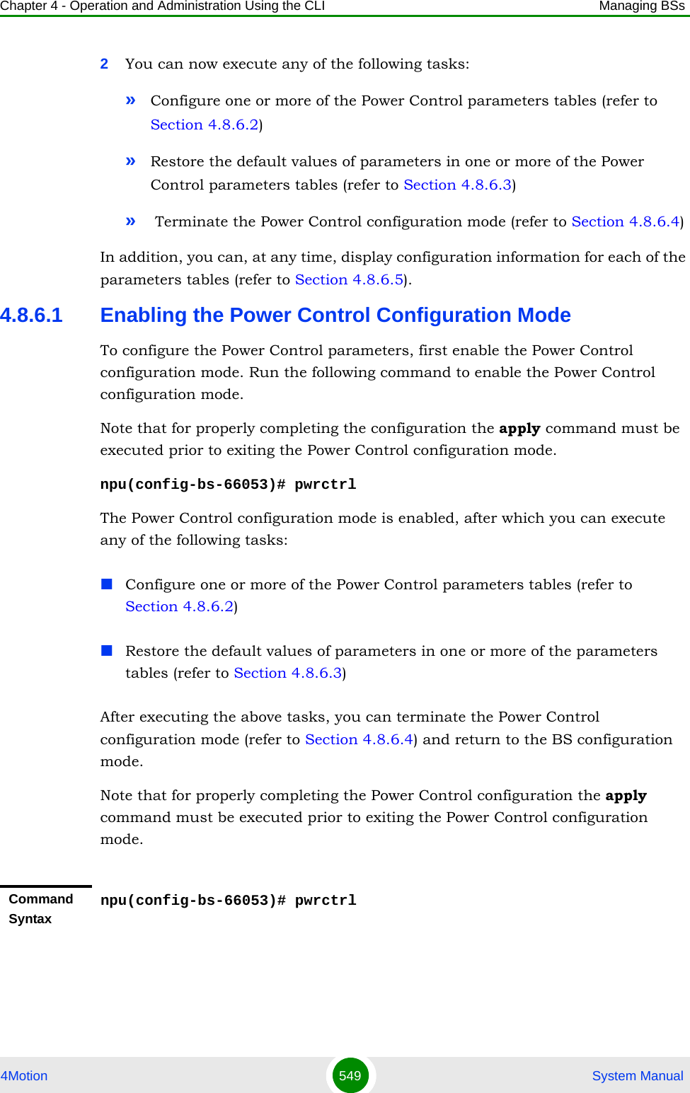
![Chapter 4 - Operation and Administration Using the CLI Managing BSs4Motion 548 System Manual4.8.6 Managing Power Control Levels and Policies1Enable the Power Control configuration mode (refer to Section 4.8.6.1)Command Syntaxnpu# show srvcmaprule-all bs [<(1 to 16777215 StepSize 1)> rule-index <(1 to 255 StepSize 1)>]Privilege Level10Syntax Description Parameter Description Presence Default ValuePossible Values<(1 to 16777215 StepSize 1)>The BS ID Specify a value for this parameter if you want to display all parameters of a specific Service Mapping Rule. Do not specify a value for this parameter if you want to display all parameters of all Service Mapping Rules.Optional N/A 1-16777215rule-index <(1 to 255 StepSize 1)>]The Service Mapping Rule index. To be used only if you want to display all parameters of a specific Service Mapping Rule.Optional N/A 1-255Command ModesGlobal command modeTo configure a the Power Control Levels and Policies:](https://usermanual.wiki/Alvarion-Technologies/BMAX-OR-25.Manual-3/User-Guide-1114031-Page-67.png)
![Chapter 4 - Operation and Administration Using the CLI Managing BSs4Motion 550 System Manual4.8.6.2 Configuring Power Control ParametersAfter enabling the Power Control configuration mode you can configure the following parameters tables:Target Noise and Interference Level (refer to Section 4.8.6.2.1)Maximum EIRP (refer to Section 4.8.6.2.2)Required C/N Level (refer to Section 4.8.6.2.3)Open Loop Correction Policy (refer to Section 4.8.6.2.4)Open Loop Correction Range (refer to Section 4.8.6.2.5)Closed Loop - Unstable MS (refer to Section 4.8.6.2.6)Closed Loop - MS in Network Entry (refer to Section 4.8.6.2.7)Closed Loop Correction Range (refer to Section 4.8.6.2.8)4.8.6.2.1 Configuring Power Control Target Noise and Interference Level ParametersThe Target Noise and Interference Level table enables defining the target limits for various noise and interference levels.To configure the Target Noise and Interference Levels, run the following command:npu(config-bs-66053-pwrctrl)# nilevels [cqi-ack-ranging <(-150 to -22.5 StepSize 0.5)>] [pusc <(-150 to -22.5 StepSize 0.5)>]Privilege Level10Command Modesbs configuration modeIMPORTANTAfter completing the Power Control configuration,do not forget to execute the apply command before exiting the Power Control configuration mode:npu(config-bs-66053-pwrctrl)# apply](https://usermanual.wiki/Alvarion-Technologies/BMAX-OR-25.Manual-3/User-Guide-1114031-Page-69.png)
![Chapter 4 - Operation and Administration Using the CLI Managing BSs4Motion 551 System Manual4.8.6.2.2 Configuring the Power Control Maximum EIRPThe maxeirxp parameter enables defining the maximum effective isotropic received power at the BS for Initial ranging.To configure the maxeirxp, run the following command:npu(config-bs-66053-pwrctrl)# maxeirxp <(-140 to -40 StepSize 1)>IMPORTANTWhen creating a new BS, at least one of the Power Control Target Noise and Interference Level parameters must be configured explicitly (even if configured to the default value).Command Syntaxnpu(config-bs-66053-pwrctrl)# nilevels [cqi-ack-ranging <(-150 to -22.5 StepSize 0.5)> ] [pusc <(-150 to -22.5 StepSize 0.5)> ]Privilege Level10Syntax Description Parameter Description Presence Default Value Possible Values[cqi-ack-ranging <(-150 to -22.5 StepSize 0.5)> ]>Target Noise and interference level for the CQI, ACK and periodic ranging regions, in dBm.Optional -128 -150 to -22.5 in steps of 0.5[pusc <(-150 to -22.5 StepSize 0.5)> ]Target Noise and interference level for the PUSC zone, in dBmOptional -128 -150 to -22.5 in steps of 0.5Command Modesbs power control configuration mode IMPORTANTWhen creating a new BS, the maxeirxp parameters must be configured explicitly (even if configured to the default value).](https://usermanual.wiki/Alvarion-Technologies/BMAX-OR-25.Manual-3/User-Guide-1114031-Page-70.png)
![Chapter 4 - Operation and Administration Using the CLI Managing BSs4Motion 552 System Manual4.8.6.2.3 Configuring the Power Control Required C/N Level ParametersThe Required C/N Levels table enables defining the Carrier to Noise Ratios required for various types of transmissions.To configure the Required C/N Levels, run the following command:npu(config-bs-66053-pwrctrl)# requiredcnr [ack <(-20 to 50 StepSize 1)>] [cqi <(-20 to 50 StepSize 1)>] [cdma <(-20 to 50 StepSize 1)>] [qpsk-1by2 <(-20 to 50 StepSize 1)>] [qpsk-3by4 <(-20 to 50 StepSize 1)>] [qam16-1by2 <(-20 to 50 StepSize 1)>] [qam16-3by4 <(-20 to 50 StepSize 1)>] [qam64-1by2 <(-20 to 50 StepSize 1)>] [qam64-2by3 <(-20 to 50 StepSize 1)>] [qam64-3by4 <(-20 to 50 StepSize 1)>] [qam64-5by6 <(-20 to 50 StepSize 1)>]Command Syntaxnpu(config-bs-66053-pwrctrl)# maxeirxp <(-140 to -40 StepSize 1)>Privilege Level10Syntax Description Parameter Description Presence Default Value Possible Valuesmaxeirxp <(-140 to -40 StepSize 1)>The maximum effective isotropic received power at the BS for Initial ranging, in dBm.Optional -124 -140 to -40Command Modesbs power control configuration mode IMPORTANTWhen creating a new BS, at least one of the Power Control Required C/N Level parameters must be configured explicitly (even if configured to the default value).](https://usermanual.wiki/Alvarion-Technologies/BMAX-OR-25.Manual-3/User-Guide-1114031-Page-71.png)
![Chapter 4 - Operation and Administration Using the CLI Managing BSs4Motion 553 System ManualCommand Syntaxnpu(config-bs-66053-pwrctrl)# requiredcnr [ack <(-20 to 50 StepSize 1)> ] [cqi <(-20 to 50 StepSize 1)> ] [cdma <(-20 to 50 StepSize 1)> ] [qpsk-1by2 <(-20 to 50 StepSize 1)> ] [qpsk-3by4 <(-20 to 50 StepSize 1)> ] [qam16-1by2 <(-20 to 50 StepSize 1)> ] [qam16-3by4 <(-20 to 50 StepSize 1)> ] [qam64-1by2 <(-20 to 50 StepSize 1)> ] [qam64-2by3 <(-20 to 50 StepSize 1)> ] [qam64-3by4 <(-20 to 50 StepSize 1)> ] [qam64-5by6 <(-20 to 50 StepSize 1)> ]Privilege Level10Syntax Description Parameter Description Presence Default Value Possible Values[ack <(-20 to 50 StepSize 1)> ]The C/N in dB required for sending ACK, reported to the MS for power control purposes.Optional 7 -20 to 50[cqi <(-20 to 50 StepSize 1)> ]The C/N in dB required for sending CQI, reported to the MS for power control purposes.Must be in the range from requiredcnr-ack - 8 to requiredcnr-ack + 7 (see ack parameter above)Optional 0 -20 to 50 [cdma <(-20 to 50 StepSize 1)> ]The C/N in dB required for transmitting CDMA, reported to the MS for power control purposes.Must be in the range from requiredcnr-cqi - 8 to requiredcnr-cqi + 7 (see cqi parameter above)Optional 0 -20 to 50[qpsk-1by2 <(-20 to 50 StepSize 1)> ]The C/N in dB required for transmitting using QPSK 1/2, reported to the MS for power control purposes.Must be in the range from requiredcnr-cdma - 16 to requiredcnr-cdma + 14 (see cdma parameter above)Optional 14 -20 to 50](https://usermanual.wiki/Alvarion-Technologies/BMAX-OR-25.Manual-3/User-Guide-1114031-Page-72.png)
![Chapter 4 - Operation and Administration Using the CLI Managing BSs4Motion 554 System Manual[qpsk-3by4<(-20 to 50 StepSize 1)> ]The C/N in dB required for transmitting using QPSK 3/4, reported to the MS for power control purposes.Must be in the range from requiredcnr-qpsk-1by2 - 16 to requiredcnr-qpsk-1by2 + 14 (see qpsk-1by2 parameter above)Optional 16 -20 to 50[qam16-1by2 <(-20 to 50 StepSize 1)> ]The C/N in dB required for transmitting using 16QAM 1/2, reported to the MS for power control purposes.Must be in the range from requiredcnr-qpsk-3by4 - 8 to requiredcnr-qpsk-3by4 + 7 (see qpsk-3by4 parameter above)Optional 18 -20 to 50[qam16-3by4 <(-20 to 50 StepSize 1)> ]The C/N in dB required for transmitting using 16QAM 3/4, reported to the MS for power control purposes.Must be in the range from requiredcnr-qam16-1by2 - 16 to requiredcnr-qam16-1by2 + 14 (see qam16-1by2 parameter above)Optional 22 -20 to 50qam64-1by2 <(-20 to 50 StepSize 1)> ]The C/N in dB required for transmitting using 64QAM 1/2, reported to the MS for power control purposes.Must be in the range from requiredcnr-qam16-3by4 - 16 to requiredcnr-qam16-3by4 + 14 (see qam16-3by4 parameter above)Optional 23 -20 to 50[qam64-2by3 <(-20 to 50 StepSize 1)> ]The C/N in dB required for transmitting using 64QAM 2/3, reported to the MS for power control purposes.Must be in the range from requiredcnr-qam64-1by2 - 8 to requiredcnr-qam64-1by2 + 7 (see qam64-1by2 parameter above)Optional 23 -20 to 50](https://usermanual.wiki/Alvarion-Technologies/BMAX-OR-25.Manual-3/User-Guide-1114031-Page-73.png)
![Chapter 4 - Operation and Administration Using the CLI Managing BSs4Motion 555 System Manual4.8.6.2.4 Configuring the Power Control Open Loop Correction Policy ParametersTo configure the Open Loop Correction Policy parameters, run the following command:npu(config-bs-66053-pwrctrl)# olpolicy [positivecoefficient <(0 to 1 StepSize 0.05)>] [negativecoefficient<(0 to 1 StepSize 0.05)>] [max-positivecorrection <(0 to 20 StepSize 0.1)>] [max-negativecorrection <(0 to 20 StepSize 0.1)>][qam64-3by4 <(-20 to 50 StepSize 1)> ]The C/N in dB required for transmitting using 64QAM 3/4, reported to the MS for power control purposes.Must be in the range from requiredcnr-qam64-2by3 - 8 to requiredcnr-qam54-2by3 + 7 (see qam54-2by3 parameter above)Optional 23 -20 to 50[qam64-5by6 <(-20 to 50 StepSize 1)> ]he C/N in dB required for transmitting using 64QAM 5/6, reported to the MS for power control purposes.Must be in the range from requiredcnr-qam64-3by4 - 8 to requiredcnr-qam64-3by4 + 7 (see qam64-3by4 parameter above)Optional 23 -20 to 50Command Modesbs power control configuration mode IMPORTANTWhen creating a new BS, at least one of the Power Control Open Loop Correction Policy parameters must be configured explicitly (even if configured to the default value).Command Syntaxnpu(config-bs-66053-pwrctrl)# olpolicy [positivecoefficient <(0 to 1 StepSize 0.05)> ] [negativecoefficient<(0 to 1 StepSize 0.05)> ] [max-positivecorrection <(0 to 20 StepSize 0.1)> ] [max-negativecorrection <(0 to 20 StepSize 0.1)> ]Privilege Level10](https://usermanual.wiki/Alvarion-Technologies/BMAX-OR-25.Manual-3/User-Guide-1114031-Page-74.png)
![Chapter 4 - Operation and Administration Using the CLI Managing BSs4Motion 556 System Manual4.8.6.2.5 Configuring the Power Control Open Loop Correction Range ParametersTo configure the Open Loop Correction Range parameters, run the following command:npu(config-bs-66053-pwrctrl)# olrange [lowthrshld-linear <(-20 to 0 StepSize 0.1)>] [lowthrshld-constant <(-20 to 0 StepSize 0.1)>] [highthrshld-linear <(0 to 20 StepSize 0.1)>] [highthrshld-constant <(0 to 20 StepSize 0.1)>]Syntax Description Parameter Description Presence Default Value Possible Values[positivecoefficient <(0 to 1 StepSize 0.05)> ]Correction coefficient for open loop when giving positive correctionsOptional 0.7 0 to 1 in steps of 0.05[negativecoefficient <(0 to 1 StepSize 0.05)> ]Correction coefficient for open loop when giving negative correctionsOptional 0.7 0 to 1 in steps of 0.05[max-positivecorrection <(0 to 20 StepSize 0.1)> ]Maximum positive power correction (in dB) for open loopOptional 8 0 to 20 in steps of 0.1[max-negativecorrection <(0 to 20 StepSize 0.1)> ]Maximum negative power correction (in dB) for open loopOptional 8 0 to 20 in steps of 0.1Command Modesbs power control configuration mode IMPORTANTWhen creating a new BS, at least one of the Power Control Open Loop Correction Range parameters must be configured explicitly (even if configured to the default value).Command Syntaxnpu(config-bs-66053-pwrctrl)# olrange [lowthrshld-linear <(-20 to 0 StepSize 0.1)> ] [lowthrshld-constant <(-20 to 0 StepSize 0.1)> ] [highthrshld-linear <(0 to 20 StepSize 0.1)> ] [highthrshld-constant <(0 to 20 StepSize 0.1)> ]Privilege Level10](https://usermanual.wiki/Alvarion-Technologies/BMAX-OR-25.Manual-3/User-Guide-1114031-Page-75.png)
![Chapter 4 - Operation and Administration Using the CLI Managing BSs4Motion 557 System Manual4.8.6.2.6 Configuring the Power Control Closed Loop - Unstable MS Correction Policy ParametersTo configure the Closed Loop - Unstable MS Correction Policy parameters, run the following command:npu(config-bs-66053-pwrctrl)# clunstable [positivecoefficient <(0 to 1 StepSize 0.05)>] [negativecoefficient <(0 to 1 StepSize 0.05)>] [max-positivecorrection <(0 to 20 StepSize 0.1)>][max-negativecorrection <(0 to 20 StepSize 0.1)>]Syntax Description Parameter Description Presence Default Value Possible Values[lowthrshld-linear <(-20 to 0 StepSize 0.1)> ]The open loop correction range threshold (in dB) below which linear corrections are made.Cannot be lower than olrange-lowthrshld-constant (see below)Optional -18 -20 to 0 in steps of 0.1[lowthrshld-constant <(-20 to 0 StepSize 0.1)> ]The open loop correction range threshold (in dB) below which constant corrections are made.Optional -19 -20 to 0 in steps of 0.1[highthrshld-linear <(0 to 20 StepSize 0.1)> ]The open loop correction range threshold (in dB) above which linear corrections are made.Optional 18 0 to 20 in steps of 0.1[highthrshld-constant <(0 to 20 StepSize 0.1)> ]The open loop correction range threshold (in dB) above which constant corrections are made.Cannot be lower than olrange-highthrshld-linear (see above)Optional 19 0 to 20 in steps of 0.1Command Modesbs power control configuration mode IMPORTANTWhen creating a new BS, at least one of the Power Control Closed Loop - Unstable MS parameters must be configured explicitly (even if configured to the default value).](https://usermanual.wiki/Alvarion-Technologies/BMAX-OR-25.Manual-3/User-Guide-1114031-Page-76.png)
![Chapter 4 - Operation and Administration Using the CLI Managing BSs4Motion 558 System Manual4.8.6.2.7 Configuring the Power Control Closed Loop - MS in Network Entry Correction Policy ParametersTo configure the Closed Loop - MS in Network Entry Correction Policy parameters, run the following command:npu(config-bs-66053-pwrctrl)# clne [positivecoefficient <(0 to 1 StepSize 0.05)>] [negativecoefficient <(0 to 1 StepSize 0.05)>] [max-positivecorrection <(0 to 20 StepSize 0.1)>] [max-negativecorrection <(0 to 20 StepSize 0.1)>]Command Syntaxnpu(config-bs-66053-pwrctrl)# clunstable [positivecoefficient <(0 to 1 StepSize 0.05)> ] [negativecoefficient <(0 to 1 StepSize 0.05)> ] [max-positivecorrection <(0 to 20 StepSize 0.1)> ][max-negativecorrection <(0 to 20 StepSize 0.1)> ]Privilege Level10Syntax Description Parameter Description Presence Default Value Possible Values[positivecoefficient <(0 to 1 StepSize 0.05)> ]Correction coefficient for problematic MS in a closed loop when giving positive correctionsOptional 0.8 0 to 1 in steps of 0.05[negativecoefficient <(0 to 1 StepSize 0.05)> ]Correction coefficient for problematic MS in a closed loop when giving negative correctionsOptional 0.7 0 to 1 in steps of 0.05[max-positivecorrection <(0 to 20 StepSize 0.1)> ]Maximum positive power correction (in dB) for problematic MS in a closed loopOptional 3 0 to 20 in steps of 0.1[max-negativecorrection <(0 to 20 StepSize 0.1)> ]Maximum negative power correction (in dB) for problematic MS in a closed loopOptional 8 0 to 20 in steps of 0.1Command Modesbs power control configuration mode](https://usermanual.wiki/Alvarion-Technologies/BMAX-OR-25.Manual-3/User-Guide-1114031-Page-77.png)
![Chapter 4 - Operation and Administration Using the CLI Managing BSs4Motion 559 System Manual4.8.6.2.8 Configuring the Power Control Closed Loop Correction Range ParametersTo configure the Closed Loop Correction Range parameters, run the following command:IMPORTANTWhen creating a new BS, at least one of the Power Control Closed Loop - MS in Network Entry parameters must be configured explicitly (even if configured to the default value).Command Syntaxnpu(config-bs-66053-pwrctrl)# clne [positivecoefficient <(0 to 1 StepSize 0.05)> ] [negativecoefficient <(0 to 1 StepSize 0.05)> ] [max-positivecorrection <(0 to 20 StepSize 0.1)> ] [max-negativecorrection <(0 to 20 StepSize 0.1)> ]Privilege Level10Syntax Description Parameter Description Presence Default Value Possible Values[positivecoefficient <(0 to 1 StepSize 0.05)> ]Correction coefficient for network entry in closed loop when giving positive correctionsOptional 0.7 0 to 1 dB in steps of 0.05[negativecoefficient <(0 to 1 StepSize 0.05)> ]Correction coefficient for network entry in closed loop when giving negative correctionsOptional 0.7 0 to 1 dB in steps of 0.05[max-positivecorrection <(0 to 20 StepSize 0.1)> ]Maximum positive power correction (in dB) for network entry in closed loopOptional 8 0 to 20 in steps of 0.1[max-negativecorrection <(0 to 20 StepSize 0.1)> ]Maximum negative power correction (in dB) for network entry in closed loopOptional 8 0 to 20 in steps of 0.1Command Modesbs power control configuration mode](https://usermanual.wiki/Alvarion-Technologies/BMAX-OR-25.Manual-3/User-Guide-1114031-Page-78.png)
![Chapter 4 - Operation and Administration Using the CLI Managing BSs4Motion 560 System Manualnpu(config-bs-66053-pwrctrl)# clrange [lowthrshld-linear <(-20 to 0 StepSize 0.1)>] [lowthrshld-constant <(-20 to 0 StepSize 0.1)>] [highthrshld-linear <(0 to 20 StepSize 0.1)>] [highthrshld-constant <(0 to 20 StepSize 0.1)>]IMPORTANTWhen creating a new BS, at least one of the Power Control Closed Loop Correction Range parameters must be configured explicitly (even if configured to the default value).Command Syntaxnpu(config-bs-66053-pwrctrl)# clrange [lowthrshld-linear <(-20 to 0 StepSize 0.1)> ] [lowthrshld-constant <(-20 to 0 StepSize 0.1)> ] [highthrshld-linear <(0 to 20 StepSize 0.1)> ] [highthrshld-constant <(0 to 20 StepSize 0.1)> ]Privilege Level10Syntax Description Parameter Description Presence Default Value Possible Values[lowthrshld-linear <(-20 to 0 StepSize 0.1)> ]Closed loop correction range threshold (in dB) below which linear corrections are made.Cannot be lower than clrange-lowthrshld-constant (see below)Optional -2 -20 to 0 in steps of 0.1lowthrshld-constant <(-20 to 0 StepSize 0.1)> ]Closed loop correction range threshold (in dB) below which constant corrections are made.Optional -8 -20 to 0 in steps of 0.1[highthrshld-linear <(0 to 20 StepSize 0.1)> ]Closed loop correction range threshold (in dB) above which linear corrections are made.Optional 2 -20 to 0 in steps of 0.1[highthrshld-constant <(0 to 20 StepSize 0.1)> ]Closed loop correction range threshold (in dB) above which constant corrections are made.Cannot be lower than clrange-highthrshld-linear (see above)Optional 8 -20 to 0 in steps of 0.1](https://usermanual.wiki/Alvarion-Technologies/BMAX-OR-25.Manual-3/User-Guide-1114031-Page-79.png)
![Chapter 4 - Operation and Administration Using the CLI Managing BSs4Motion 561 System Manual4.8.6.3 Restoring Default Values for Power Control Configuration ParametersAfter enabling the Power Control configuration mode you can restore the default values for parameters in the following parameters tables:Noise and Interference Level (refer to Section 4.8.6.3.1)Maximum EIRP (refer to Section 4.8.6.3.2)Required C/N Level (refer to Section 4.8.6.3.3)Open Loop Correction Policy (refer to Section 4.8.6.3.4)Open Loop Correction Range (refer to Section 4.8.6.3.5)Closed Loop - Unstable MS (refer to Section 4.8.6.3.6)Closed Loop - MS in Network Entry (refer to Section 4.8.6.3.7)Closed Loop Correction Range (refer to Section 4.8.6.3.8)4.8.6.3.1 Restoring the Default Values of Power Control Target Noise and Interference Level ParametersTo restore one or all of the Target Noise and Interference Level parameters to their default values, run the following command:npu(config-bs-66053-pwrctrl)# no nilevels [cqi-ack-ranging] [pusc]You can restore only one parameter to its default values by specifying only that parameter. For example, to restore only the pusc to the default value, run the following command:npu(config-bs-66053-pwrctrl)# no nilevels puscThe parameter will be restored to its default value, while the other parameter will remain unchanged.To restore all Target Noise and Interference Level parameters to their default value, run the following command:npu(config-bs-66053-pwrctrl)# no nilevelsCommand Modesbs power control configuration mode](https://usermanual.wiki/Alvarion-Technologies/BMAX-OR-25.Manual-3/User-Guide-1114031-Page-80.png)
![Chapter 4 - Operation and Administration Using the CLI Managing BSs4Motion 562 System Manual4.8.6.3.2 Restoring the Default Values of the Power Control Maximum EIRP ParameterTo restore the maxeirxp parameter to its default value, run the following command:npu(config-bs-66053-pwrctrl)# no maxeirxp4.8.6.3.3 Restoring the Default Values of Power Control Required C/N Level ParametersTo restore some or all of the Required C/N Levels parameters to their default values, run the following command:NOTERefer to Section 4.8.6.2.1 for a description and default values of these parameters.Command Syntaxnpu(config-bs-66053-pwrctrl)# no nilevels [cqi-ack-ranging ] [pusc]Privilege Level10Command Modesbs power control configuration modeNOTERefer to Section 4.8.6.2.2 for a description and default value of this parameter.Command Syntaxnpu(config-bs-66053-pwrctrl)# no maxeirxpPrivilege Level10Command Modesbs power control configuration mode](https://usermanual.wiki/Alvarion-Technologies/BMAX-OR-25.Manual-3/User-Guide-1114031-Page-81.png)
![Chapter 4 - Operation and Administration Using the CLI Managing BSs4Motion 563 System Manualnpu(config-bs-66053-pwrctrl)# no requiredcnr [ack] [cqi] [cdma] [qpsk-1by2] [qpsk-3by4] [qam16-1by2] [qam16-3by4] [qam64-1by2] [qam64-2by3] [qam64-3by4] [qam64-5by6]You can restore only some parameters to their default values by specifying only those parameter. For example, to restore only the ack and cqi parameters to the default values, run the following command:npu(config-bs-66053-pwrctrl)# no requiredcnr ack cqiThese parameters will be restored to their default value, while the other parameters will remain unchanged.To restore all Required C/N Levels parameters to their default value, run the following command:npu(config-bs-66053-pwrctrl)# no requiredcnr4.8.6.3.4 Restoring the Default Values of Power Control Open Loop Correction Policy ParametersTo restore some or all of the Open Loop Correction Policy parameters to their default values, run the following command:npu(config-bs-66053-pwrctrl)# no olpolicy [positivecoefficient] [negativecoefficient] [max-positivecorrection] [max-negativecorrection]You can restore only some parameters to their default values by specifying only those parameters. For example, to restore only the positivecoefficient and negativecoefficient parameters to the default values, run the following command:NOTERefer to Section 4.8.6.2.3 for a description and default values of these parameters.Command Syntaxnpu(config-bs-66053-pwrctrl)# no requiredcnr [ack ] [cqi ] [cdma ] [qpsk-1by2 ] [qpsk-3by4 ] [qam16-1by2 ] [qam16-3by4 ] [qam64-1by2 ] [qam64-2by3 ] [qam64-3by4 ] [qam64-5by6 ]Privilege Level10Command Modesbs power control configuration mode](https://usermanual.wiki/Alvarion-Technologies/BMAX-OR-25.Manual-3/User-Guide-1114031-Page-82.png)
![Chapter 4 - Operation and Administration Using the CLI Managing BSs4Motion 564 System Manualnpu(config-bs-66053-pwrctrl)# no olpolicy positivecoefficient negativecoefficientThese parameters will be restored to their default value, while the other parameters will remain unchanged.To restore all Open Loop Correction Policy parameters to their default value, run the following command:npu(config-bs-66053-pwrctrl)# no olpolicy4.8.6.3.5 Restoring the Default Values of Power Control Open Loop Correction Range ParametersTo restore some or all of the Open Loop Correction Range parameters to their default values, run the following command:npu(config-bs-66053-pwrctrl)# no olrange [lowthrshld-linear] [lowthrshld-constant] [highthrshld-linear] [highthrshld-constant]You can restore only some parameters to their default values by specifying only those parameters. For example, to restore only the highthrshld-linear and highthrshld-constant parameters to the default values, run the following command:npu(config-bs-66053-pwrctrl)# no olrange highthrshld-linear highthrshld-constantThese parameters will be restored to their default value, while the other parameters will remain unchanged.NOTERefer to Section 4.8.6.2.4 for a description and default values of these parameters.Command Syntaxnpu(config-bs-66053-pwrctrl)# no olpolicy [positivecoefficient ] [negativecoefficient ] [max-positivecorrection ] [max-negativecorrection ]Privilege Level10Command Modesbs power control configuration mode](https://usermanual.wiki/Alvarion-Technologies/BMAX-OR-25.Manual-3/User-Guide-1114031-Page-83.png)
![Chapter 4 - Operation and Administration Using the CLI Managing BSs4Motion 565 System ManualTo restore all Open Loop Correction Range parameters to their default value, run the following command:npu(config-bs-66053-pwrctrl)# no olrange4.8.6.3.6 Restoring the Default Values of Power Control Closed Loop - Unstable MS Correction Policy ParametersTo restore some or all of the Open Loop - Unstable MS Correction Policy parameters to their default values, run the following command:npu(config-bs-66053-pwrctrl)# no clunstable [positivecoefficient] [negativecoefficient] [max-positivecorrection] [max-negativecorrection]You can restore only some parameters to their default values by specifying only those parameters. For example, to restore only the positivecoefficient and negativecoefficient parameters to the default values, run the following command:npu(config-bs-66053-pwrctrl)# no clunstable positivecoefficient negativecoefficientThese parameters will be restored to their default value, while the other parameters will remain unchanged.To restore all Open Loop - Unstable MS parameters to their default value, run the following command:npu(config-bs-66053-pwrctrl)# no clunstableNOTERefer to Section 4.8.6.2.5 for a description and default values of these parameters.Command Syntaxnpu(config-bs-66053-pwrctrl)# no olrange [lowthrshld-linear ] [lowthrshld-constant ] [highthrshld-linear ] [highthrshld-constant ]Privilege Level10Command Modesbs power control configuration modeNOTERefer to Section 4.8.6.2.6 for a description and default values of these parameters.](https://usermanual.wiki/Alvarion-Technologies/BMAX-OR-25.Manual-3/User-Guide-1114031-Page-84.png)
![Chapter 4 - Operation and Administration Using the CLI Managing BSs4Motion 566 System Manual4.8.6.3.7 Restoring the Default Values of Power Control Closed Loop - MS in Network Entry Correction Policy ParametersTo restore some or all of the Open Loop - MS in Network Entry Correction Policy parameters to their default values, run the following command:npu(config-bs-66053-pwrctrl)# no clne [positivecoefficient] [negativecoefficient] [max-positivecorrection] [max-negativecorrection]You can restore only some parameters to their default values by specifying only those parameters. For example, to restore only the positivecoefficient and negativecoefficient parameters to the default values, run the following command:npu(config-bs-66053-pwrctrl)# no clne positivecoefficient negativecoefficientThese parameters will be restored to their default value, while the other parameters will remain unchanged.To restore all Open Loop - MS in Network Entry parameters to their default value, run the following command:npu(config-bs-66053-pwrctrl)# no clneCommand Syntaxnpu(config-bs-66053-pwrctrl)# no clunstable [positivecoefficient ] [negativecoefficient ] [max-positivecorrection ] [max-negativecorrection ]Privilege Level10Command Modesbs power control configuration modeNOTERefer to Section 4.8.6.2.7 for a description and default values of these parameters.Command Syntaxnpu(config-bs-66053-pwrctrl)# no clne [positivecoefficient ] [negativecoefficient ] [max-positivecorrection ] [max-negativecorrection ]](https://usermanual.wiki/Alvarion-Technologies/BMAX-OR-25.Manual-3/User-Guide-1114031-Page-85.png)
![Chapter 4 - Operation and Administration Using the CLI Managing BSs4Motion 567 System Manual4.8.6.3.8 Restoring the Default Values of Power Control Closed Loop Correction Range ParametersTo restore some or all of the Closed Loop Correction Range parameters to their default values, run the following command:npu(config-bs-66053-pwrctrl)# no clrange [lowthrshld-linear] [lowthrshld-constant] [highthrshld-linear] [highthrshld-constant]You can restore only some parameters to their default values by specifying only those parameters. For example, to restore only the highthrshld-linear and highthrshld-constant parameters to the default values, run the following command:npu(config-bs-66053-pwrctrl)# no clrange highthrshld-linear highthrshld-constantThese parameters will be restored to their default value, while the other parameters will remain unchanged.To restore all Closed Loop Correction Range parameters to their default value, run the following command:npu(config-bs-66053-pwrctrl)# no clrangePrivilege Level10Command Modesbs power control configuration modeNOTERefer to Section 4.8.6.2.8 for a description and default values of these parameters.Command Syntaxnpu(config-bs-66053-pwrctrl)# no clrange [lowthrshld-linear ] [lowthrshld-constant ] [highthrshld-linear ] [highthrshld-constant ]Privilege Level10Command Modesbs power control configuration mode](https://usermanual.wiki/Alvarion-Technologies/BMAX-OR-25.Manual-3/User-Guide-1114031-Page-86.png)
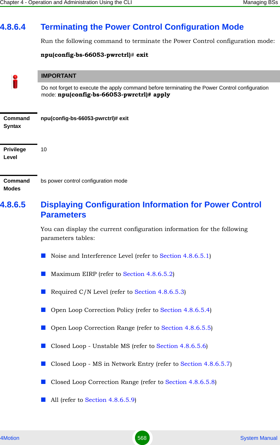
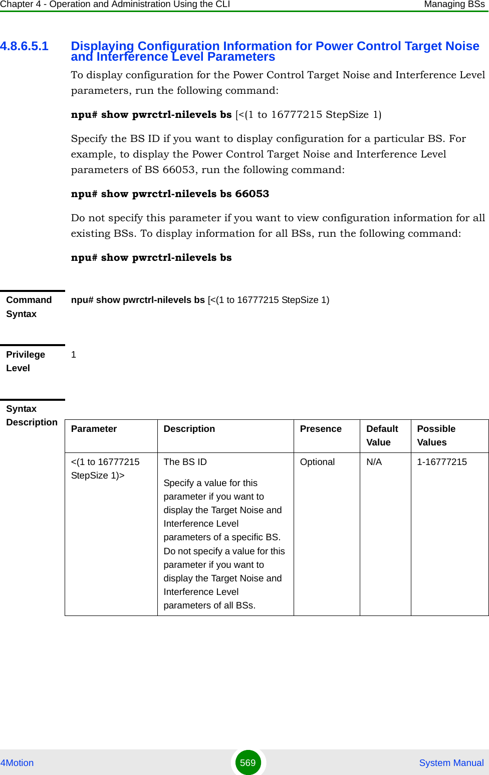
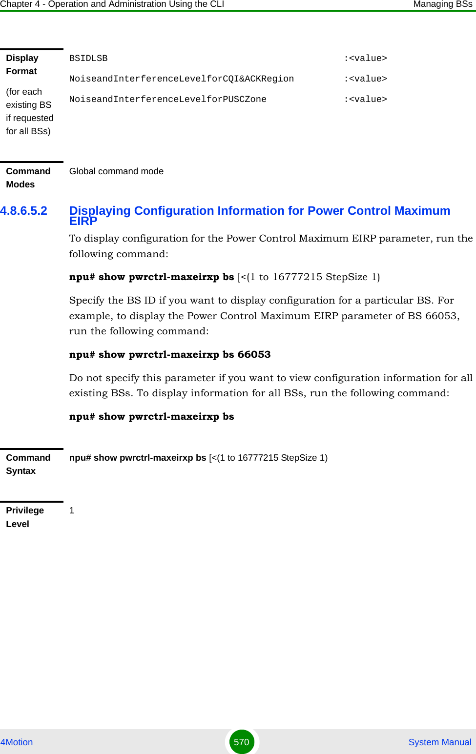
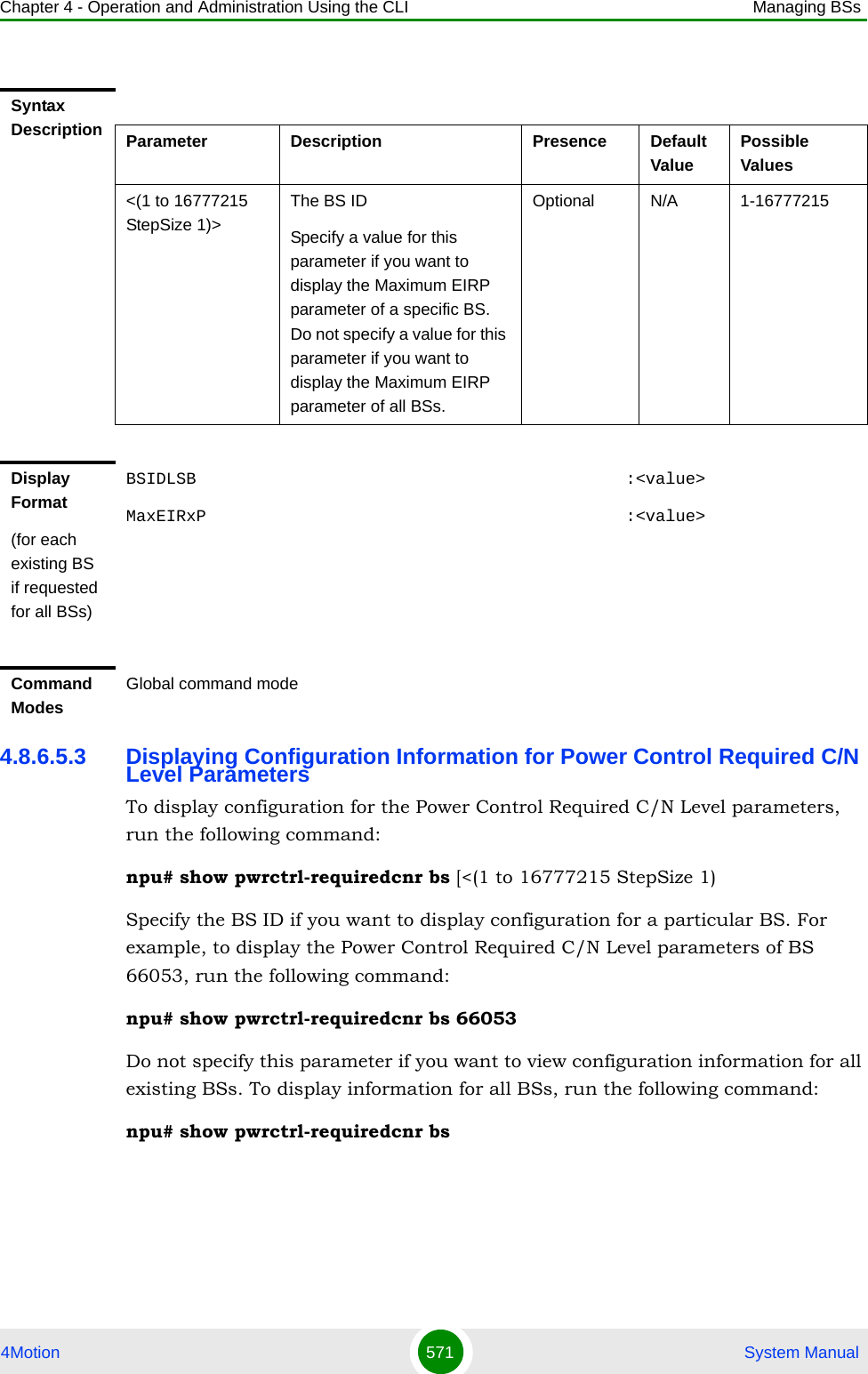
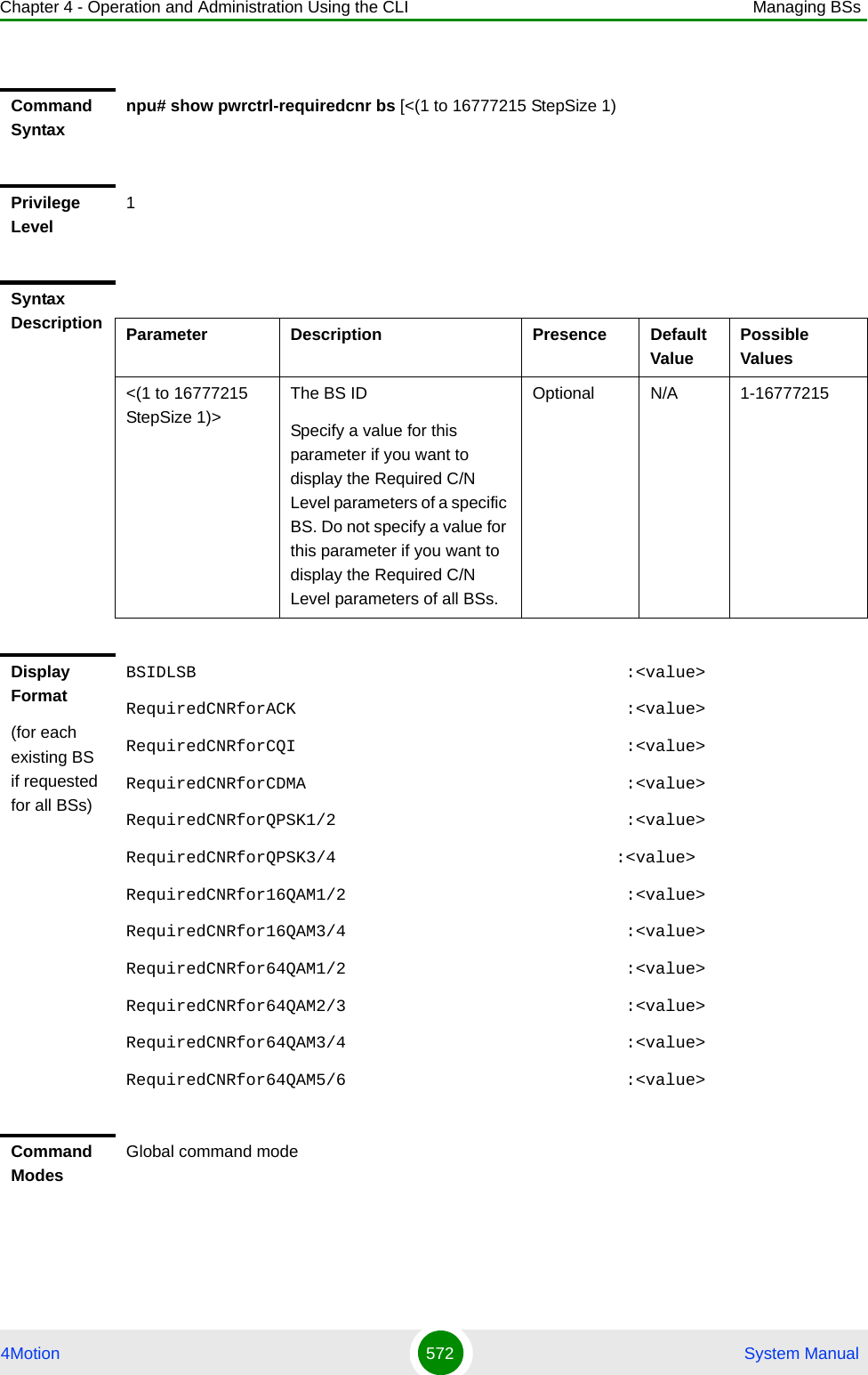

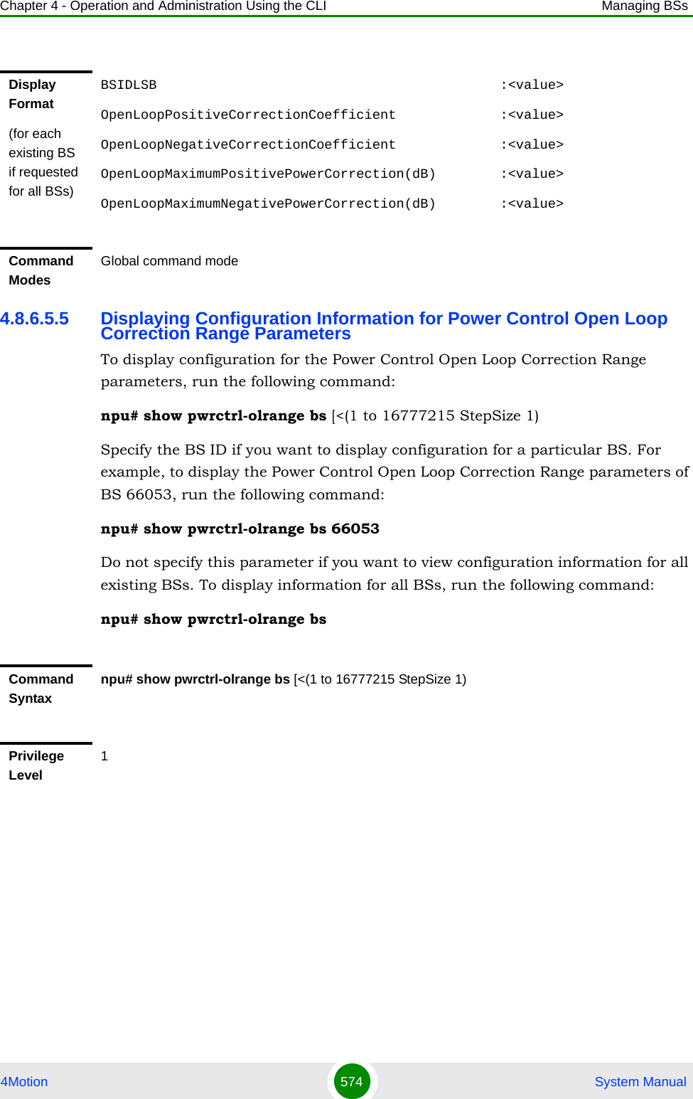
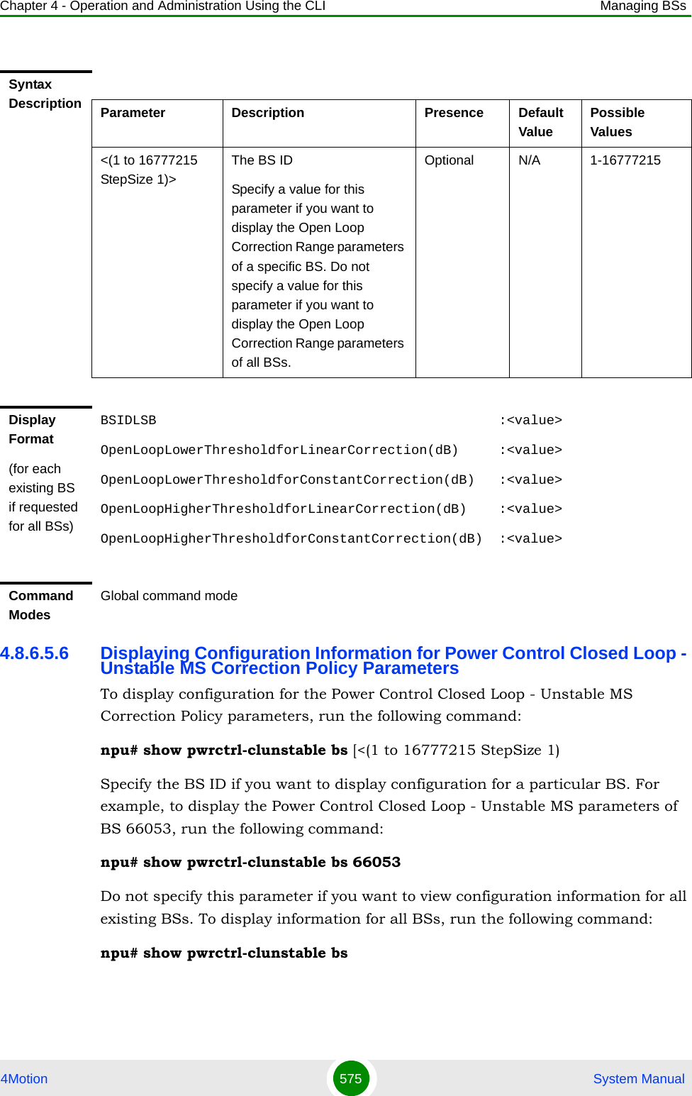
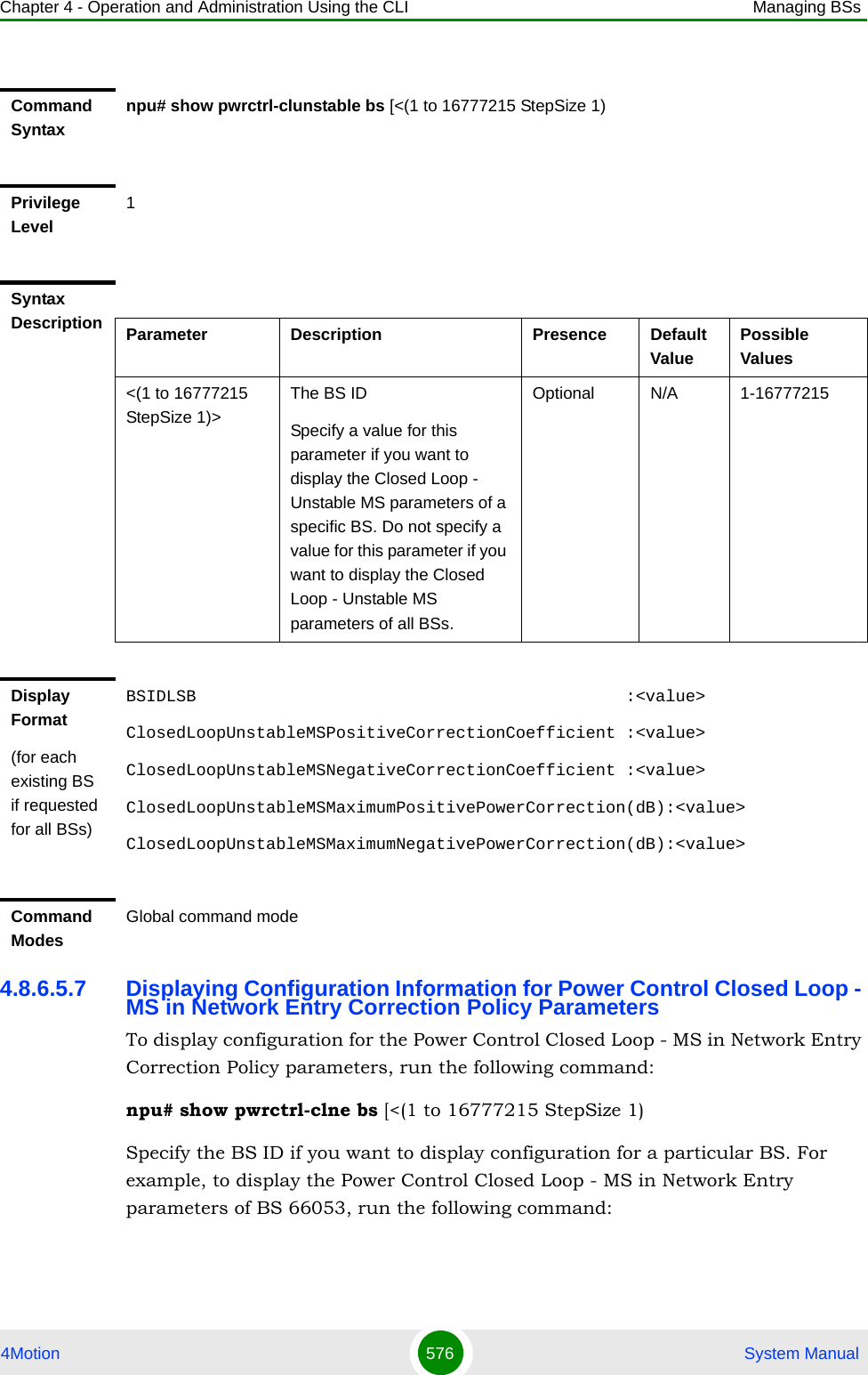
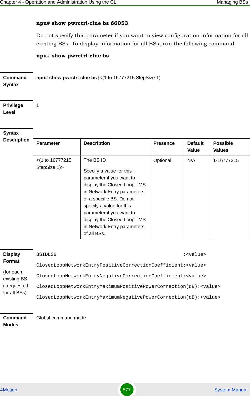

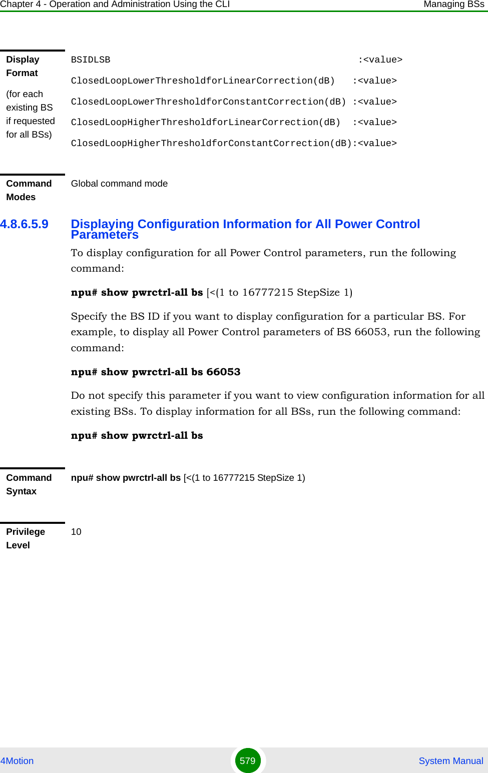
![Chapter 4 - Operation and Administration Using the CLI Managing BSs4Motion 580 System Manual4.8.7 Managing BS Feedback Allocation ParametersAfter enabling the BS configuration mode, you can execute the following tasks:Configure one or more of the Feedback Allocation parameters (refer to Section 4.8.7.1).Restore the default values of one or all of the Feedback Allocation parameters (refer to Section 4.8.7.2).You can display configuration information for the Feedback Allocation parameters of a selected or all existing BSs (refer to Section 4.8.7.3).4.8.7.1 Configuring Feedback Allocation ParametersFrom the BS configuration mode, run the following command:npu(config-bs-66053)# feedbackalloc [pr-cdma <(0 to 12000 StepSize 1)> ] [ir-cdma <(0 to 12000 StepSize 1)> ] [max-cqi <(0 to 29 StepSize 1)> ] [ert-poll-enable {true | false} ]Syntax Description Parameter Description Presence Default ValuePossible Values<(1 to 16777215 StepSize 1)>The BS ID Specify a value for this parameter if you want to display all Power Control parameters of a specific BS. Do not specify a value for this parameter if you want to display all Power Control parameters of all BSs.Optional N/A 1-16777215Command ModesGlobal command modeTo configure the Feedback Allocation Parameters:](https://usermanual.wiki/Alvarion-Technologies/BMAX-OR-25.Manual-3/User-Guide-1114031-Page-99.png)
![Chapter 4 - Operation and Administration Using the CLI Managing BSs4Motion 581 System Manual* The default value for the mandatory max-cqi parameter is be 7 for bw=5MHz and 19 for bw=7 or 10 MHz.IMPORTANTWhen creating a new BS, the mandatory max-cqi parameter must be configured. Typically it should be configured to 7 for bandwidth=5MHz and 19 for bandwidth=7 or 10 MHz.Command Syntaxnpu(config-bs-66053)# feedbackalloc [pr-cdma <(0 to 12000 StepSize 1)> ] [ir-cdma <(0 to 12000 StepSize 1)> ] [max-cqi <(0 to 29 StepSize 1)> ] [ert-poll-enable {true | false} ]Privilege Level10Syntax Description Parameter Description Presence Default Value Possible Values[pr-cdma <(0 to 12000 StepSize 1)> ]The period of PR CDMA allocations, in frames.Cannot be higher than ir-cdma (see below)Optional 5 0 - 12000[ir-cdma <(0 to 12000 StepSize 1)> ]The period of IR CDMA allocations, in framesOptional 20 0 - 12000[max-cqi <(0 to 29 StepSize 1)> ]The maximum size allowed for the CQI region, in subchannels.Mandatory when creating a new BS.N/A* 0-11 for bw=5MHz 0-29 for bw=7 or 10 MHz[ert-poll-enable {true | false} ]Defines the BS's behavior (whether polling is enabled or not) upon reception of zero size BW requests.Optional true trueFalseCommand Modesbs configuration mode](https://usermanual.wiki/Alvarion-Technologies/BMAX-OR-25.Manual-3/User-Guide-1114031-Page-100.png)
![Chapter 4 - Operation and Administration Using the CLI Managing BSs4Motion 582 System Manual4.8.7.2 Restoring the Default Values of Feedback Allocation ParametersTo restore one or all of the Feedback Allocation non-mandatory parameters to their default values, run the following command:npu(config-bs-66053)# no feedbackalloc [pr-cdma] [ir-cdma] [ert-poll-enable]You can restore only some parameters to their default values by specifying only those parameters. For example, to restore only the pr-cdma and ir-cdma parameters to the default values, run the following command:npu(config-bs-66053)# no feedbackalloc pr-cdma ir-cdmaThese parameters will be restored to their default value, while the other parameters will remain unchanged.To restore all Feedback Allocation non-mandatory parameters to their default value, run the following command:npu(config-bs-66053)# no feedbackalloc4.8.7.3 Displaying Configuration Information for Feedback Allocation ParametersTo display configuration information for Feedback Allocation parameters, run the following command:npu# show feedbackalloc bs [<(1 to 16777215 StepSize 1)NOTERefer to Section 4.8.7.1 for a description and default values of these parameters.Command Syntaxnpu(config-bs-66053)# no feedbackalloc [pr-cdma ] [ir-cdma ] [ert-poll-enable]Privilege Level10Command Modesbs configuration mode](https://usermanual.wiki/Alvarion-Technologies/BMAX-OR-25.Manual-3/User-Guide-1114031-Page-101.png)
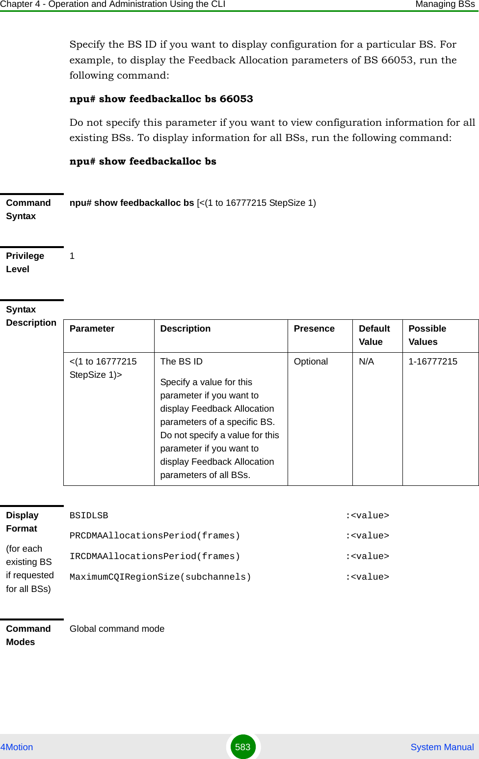
![Chapter 4 - Operation and Administration Using the CLI Managing BSs4Motion 584 System Manual4.8.8 Managing Neighbor Advertisement ParametersAfter enabling the BS configuration mode, you can execute the following tasks:Configure one or more of the Neighbor Advertisement parameters (refer to Section 4.8.8.1).Restore the default values of one or all of the Neighbor Advertisement parameters (refer to Section 4.8.8.2).You can display configuration information for the Neighbor Advertisement parameters of a selected or all existing BSs (refer to Section 4.8.8.3).4.8.8.1 Configuring Neighbor Advertisement ParametersFrom the BS configuration mode, run the following command:npu(config-bs-66053)# nbradvertise [mininterval-normalload <(0 to 100 StepSize 0.1)>] [mininterval-highload <(0 to 100 StepSize 0.1)>] [triggersetup <(0 to 100 StepSize 0.1)>]To configure the Neighbor Advertisement Parameters:IMPORTANTWhen creating a new BS, at least one of the Neighbour Advertisement parameters must be configured explicitly (even if configured to the default value).Command Syntaxnpu(config-bs-66053)# nbradvertise [mininterval-normalload <(0 to 100 StepSize 0.1)> ] [mininterval-highload <(0 to 100 StepSize 0.1)> ] [triggersetup <(0 to 100 StepSize 0.1)> ]Privilege Level10Syntax Description Parameter Description Presence Default Value Possible Values](https://usermanual.wiki/Alvarion-Technologies/BMAX-OR-25.Manual-3/User-Guide-1114031-Page-103.png)
![Chapter 4 - Operation and Administration Using the CLI Managing BSs4Motion 585 System Manual4.8.8.2 Restoring the Default Values of Neighbor Advertisement ParametersTo restore one or all of the Neighbor Advertisement parameters to their default values, run the following command:npu(config-bs-66053)# no nbradvertise [mininterval-normalload] [mininterval-highload] [triggersetup]You can restore only some parameters to their default values by specifying only those parameters. For example, to restore only the mininterval-normalload parameters to the default values, run the following command:npu(config-bs-66053)# no nbradvertise mininterval-normalloadThis parameter will be restored to its default value, while the other parameters will remain unchanged.To restore all Neighbor Advertisement parameters to their default value, run the following command:npu(config-bs-66053)# no nbradvertise[mininterval-normalload <(0 to 100 StepSize 0.1)> ]The minimum interval (in seconds) between NBRADV transmissions in normal load state.Optional 0.5 0 -100 in steps of 0.1[mininterval-highload <(0 to 100 StepSize 0.1)> ]The minimum interval (in seconds) between NBRADV transmissions in high load state.Optional 4 0 -100 in steps of 0.1[triggersetup <(0 to 100 StepSize 0.1)> ]The periodic NBRADV transmission interval, in secondsOptional 10 0 - 100 in steps of 0.1Command Modesbs configuration modeNOTERefer to Section 4.8.8.1 for a description and default values of these parameters.Command Syntaxnpu(config-bs-66053)# no nbradvertise [mininterval-normalload] [mininterval-highload] [triggersetup]](https://usermanual.wiki/Alvarion-Technologies/BMAX-OR-25.Manual-3/User-Guide-1114031-Page-104.png)
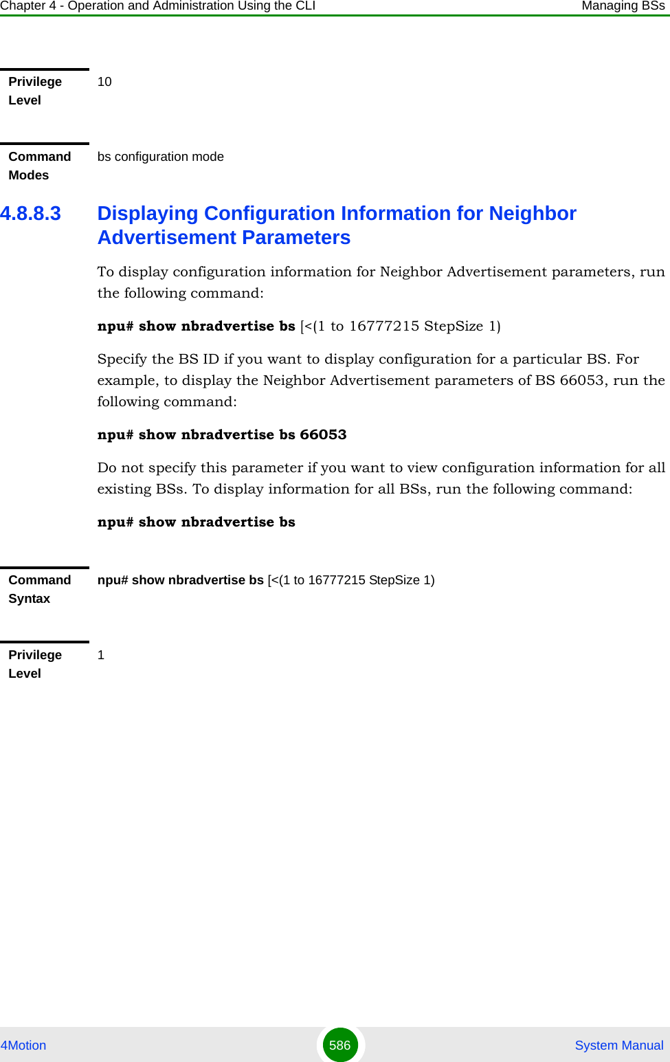
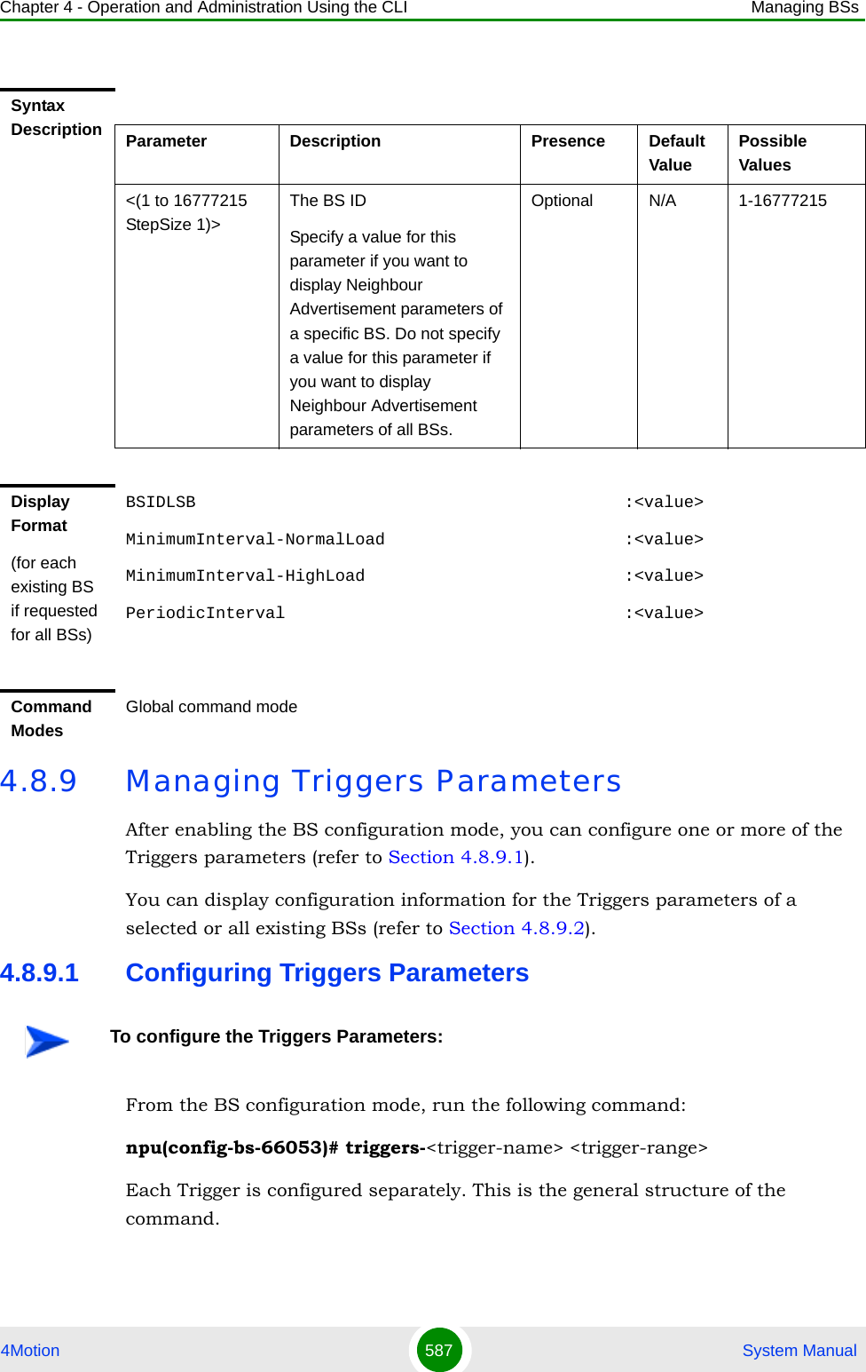
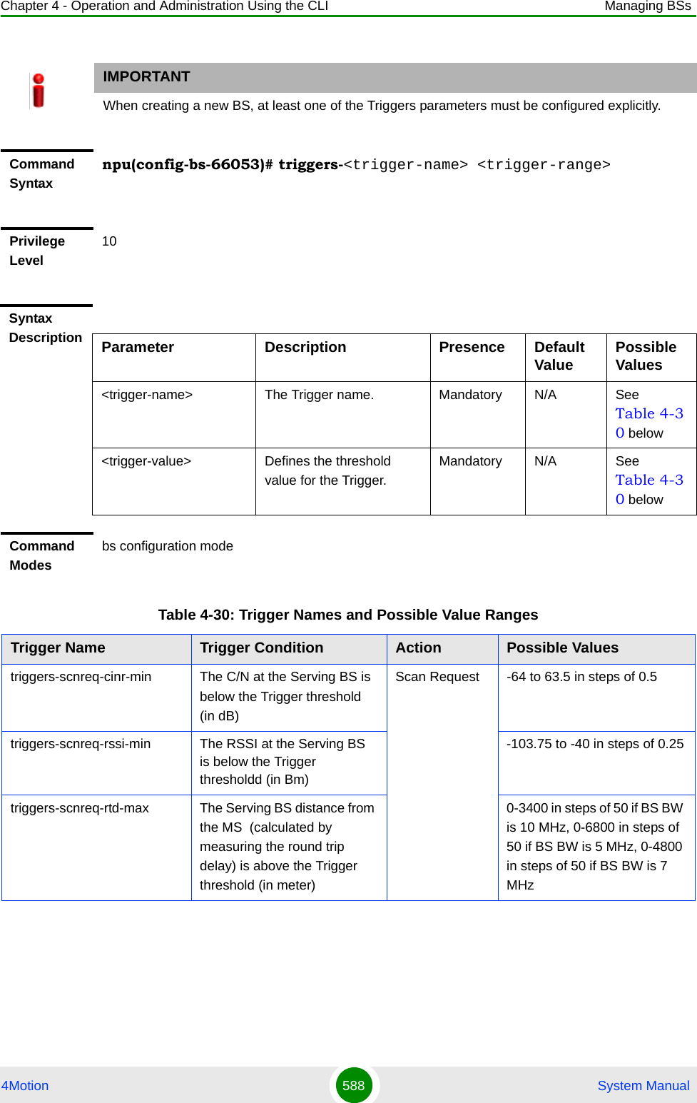
![Chapter 4 - Operation and Administration Using the CLI Managing BSs4Motion 589 System Manual4.8.9.2 Displaying Configuration Information for Triggers ParametersTo display configuration information for Triggers parameters, run the following command:npu# show triggers bs [<(1 to 16777215 StepSize 1)> TrigName {scnReqCinrMin | scnReqRssiMin | scnReqRtdMax | hoReqCinrMaxNbs | hoReqRssiMaxNbs | hoReqCinrMargin | hoReqRssiMargin | hoReqRtdMax | hoReqCinrMinSbs | hoReqRssiMinSbs}]Specify the BS ID and Trigger name if you want to display configuration for a particular Trigger. For example, to display the scnReqCinrMin parameters of BS 66053, run the following command:npu# show triggers bs 66053 TrigName scnReqCinrMintriggers-horeq-cinr-margin The C/N at the Neighbour BS minus the C/N at the Serving BS is above the Trigger threshold (in dB)Handover Request-64 to 63.5 in steps of 0.5triggers-horeq-cinr-max The C/N at the Neighbour BS is above the Trigger threshold (in dB)-64 to 63.5 in steps of 0.5triggers-horeq-cinr-min The C/N at the Serving BS is below the Trigger threshold (in dB)-64 to 63.5 in steps of 0.5triggers-horeq-rssi-margin The RSSI at the Neighbour BS minus the RSSI at the Serving BS is above the Trigger threshold (in dBm)-32 to 31.75 in steps of 0.25triggers-horeq-rssi-max The RSSI at the Neighbour BS is above the Trigger threshold (in dBm)-103.75 to -40 in steps of 0.25triggers-horeq-rssi-min The RSSI at the Serving BS is below the Trigger threshold (in dBm)-103.75 to -40 in steps of 0.25triggers-horeq-rtd-max The Serving BS distance from the MS (calculated by measuring the round trip delay) is above the Trigger threshold (in meter)0-3400 in steps of 50 if BS BW is 10 MHz, 0-6800 in steps of 50 if BS BW is 5 MHz, 0-4800 in steps of 50 if BS BW is 7 MHzTable 4-30: Trigger Names and Possible Value RangesTrigger Name Trigger Condition Action Possible Values](https://usermanual.wiki/Alvarion-Technologies/BMAX-OR-25.Manual-3/User-Guide-1114031-Page-108.png)
![Chapter 4 - Operation and Administration Using the CLI Managing BSs4Motion 590 System ManualDo not specify these parameters if you want to view configuration information for all existing BSs. To display information for all BSs, run the following command:npu# show triggers bsCommand Syntaxnpu# show triggers bs [<(1 to 16777215 StepSize 1)> TrigName {scnReqCinrMin | scnReqRssiMin | scnReqRtdMax | hoReqCinrMaxNbs | hoReqRssiMaxNbs | hoReqCinrMargin | hoReqRssiMargin | hoReqRtdMax | hoReqCinrMinSbs | hoReqRssiMinSbs} ]Privilege Level1Syntax Description Parameter Description Presence Default ValuePossible Values<(1 to 16777215 StepSize 1)>The BS ID Specify a value for this parameter if you want to display a specific Trigger of a specific BS. Do not specify a value for this parameter if you want to display all Triggers parameters of all BSs.Optional N/A 1-16777215TrigName {scnReqCinrMin | scnReqRssiMin | scnReqRtdMax | hoReqCinrMaxNbs | hoReqRssiMaxNbs | hoReqCinrMargin | hoReqRssiMargin | hoReqRtdMax | hoReqCinrMinSbs | hoReqRssiMinSbs} ]The Trigger name Specify only if you want to display a specific Trigger of a specific BS. Do not specify if you want to display all Triggers parameters of all BSsscnReqCinrMinscnReqRssiMinscnReqRtdMaxhoReqCinrMaxNbshoReqRssiMaxNbshoReqCinrMarginhoReqRssiMarginhoReqRtdMaxhoReqCinrMinSbshoReqRssiMinSbs}](https://usermanual.wiki/Alvarion-Technologies/BMAX-OR-25.Manual-3/User-Guide-1114031-Page-109.png)
![Chapter 4 - Operation and Administration Using the CLI Managing BSs4Motion 591 System Manual4.8.10 Managing Trigger Setup ParametersAfter enabling the BS configuration mode, you can execute the following tasks:Configure one or more of the Trigger Setup parameters (refer to Section 4.8.10.1).Restore the default values of one or all of the Trigger Setup parameters (refer to Section 4.8.10.2).You can display configuration information for the Trigger Setup parameters of a selected or all existing BSs (refer to Section 4.8.10.3).4.8.10.1 Configuring Trigger Setup ParametersFrom the BS configuration mode, run the following command:npu(config-bs-66053)# triggersetup [hysteresismargin <(0 to 255 StepSize 1)>] [timetotrigger <(0 to 255 StepSize 1)>] [avgduration-rssi <(0 to 255 StepSize 1)>] [avgduration-cinr <(0 to 255 StepSize 1)>] [avgduration-rtd <(0 to 255 StepSize 1)>]Display Format(for a selected Trigger)BSIDLSB :<value>scnReqRssiMin :<value>Command ModesGlobal command modeTo configure the Trigger Setup Parameters:IMPORTANTWhen creating a new BS, at least one of the Trigger Setup parameters must be configured explicitly (even if configured to the default value).](https://usermanual.wiki/Alvarion-Technologies/BMAX-OR-25.Manual-3/User-Guide-1114031-Page-110.png)
![Chapter 4 - Operation and Administration Using the CLI Managing BSs4Motion 592 System ManualCommand Syntaxnpu(config-bs-66053)# triggersetup [hysteresismargin <(0 to 255 StepSize 1)> ] [timetotrigger <(0 to 255 StepSize 1)> ] [avgduration-rssi <(0 to 255 StepSize 1)> ] [avgduration-cinr <(0 to 255 StepSize 1)> ] [avgduration-rtd <(0 to 255 StepSize 1)> ]Privilege Level10Syntax Description Parameter Description Presence Default Value Possible Values[hysteresismargin <(0 to 255 StepSize 1)> ]The CINR hysteresis in dB for adding or deleting neighbors. The hysteresis margin is used by the MS in the decision whether to include a neighbor BS in a list of possible target BSs.Optional 5 0 - 255[timetotrigger <(0 to 255 StepSize 1)> ]The minimum time in milliseconds between adding or deleting a neighbor. It is the time that the MS takes to decide whether to select a neighbor BS as a possible target BS and is applicable only for HHO.Optional 50 0 - 255[avgduration-rssi <(0 to 255 StepSize 1)> ]The default RSSI average duration for triggers, in millisecondsOptional 50 0 - 255[avgduration-cinr <(0 to 255 StepSize 1)> ]The default CINR average duration for triggers, in millisecondsOptional 50 0 - 255[avgduration-rtd <(0 to 255 StepSize 1)> ]The default RTD average duration for triggers, in millisecondsOptional 50 0 - 255Command Modesbs configuration mode](https://usermanual.wiki/Alvarion-Technologies/BMAX-OR-25.Manual-3/User-Guide-1114031-Page-111.png)
![Chapter 4 - Operation and Administration Using the CLI Managing BSs4Motion 593 System Manual4.8.10.2 Restoring the Default Values of Trigger Setup ParametersTo restore one or all of the Trigger Setup parameters to their default values, run the following command:npu(config-bs-66053)# no triggersetup [hysteresismargin] [timetotrigger] [avgduration-rssi] [avgduration-cinr] [avgduration-rtd]You can restore only some parameters to their default values by specifying only those parameters. For example, to restore only the hysteresismargin parameter to the default value, run the following command:npu(config-bs-66053)# no triggersetup hysteresismarginThis parameter will be restored to its default value, while the other parameters will remain unchanged.To restore all Trigger Setup parameters to their default value, run the following command:npu(config-bs-66053)# no triggersetup4.8.10.3 Displaying Configuration Information for Trigger Setup ParametersTo display configuration information for Trigger Setup parameters, run the following command:npu# show triggersetup bs [<(1 to 16777215 StepSize 1)NOTERefer to Section 4.8.10.1 for a description and default values of these parameters.Command Syntaxnpu(config-bs-66053)# no triggersetup [hysteresismargin ] [timetotrigger ] [avgduration-rssi] [avgduration-cinr] [avgduration-rtd ]Privilege Level10Command Modesbs configuration mode](https://usermanual.wiki/Alvarion-Technologies/BMAX-OR-25.Manual-3/User-Guide-1114031-Page-112.png)
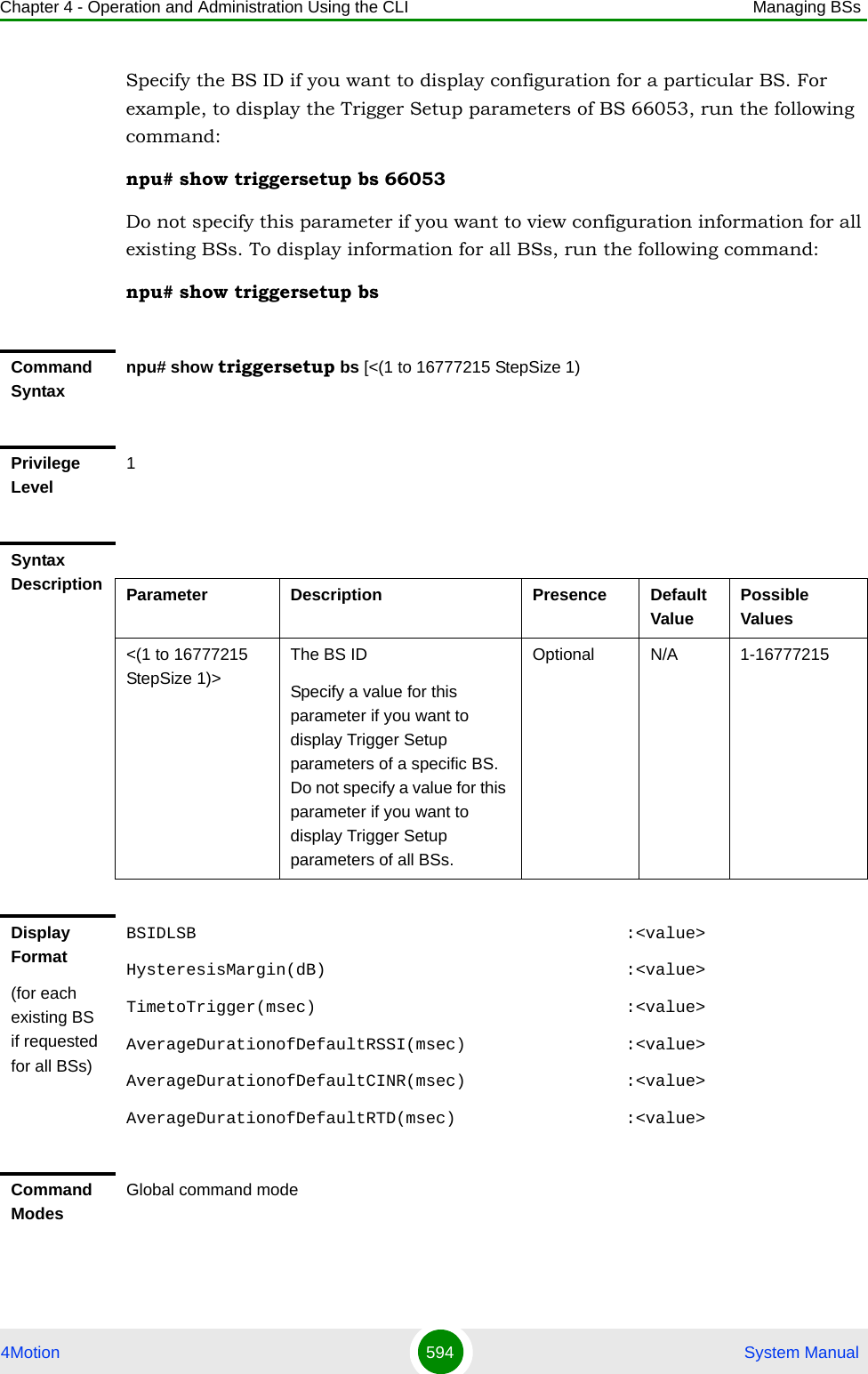
![Chapter 4 - Operation and Administration Using the CLI Managing BSs4Motion 595 System Manual4.8.11 Managing Scan Negotiation ParametersAfter enabling the BS configuration mode, you can execute the following tasks:Configure one or more of the Scan Negotiation parameters (refer to Section 4.8.11.1).Restore the default values of some or all of the Scan Negotiation parameters (refer to Section 4.8.11.2).You can display configuration information for the Scan Negotiation parameters of a selected or all existing BSs (refer to Section 4.8.11.3).4.8.11.1 Configuring Scan Negotiation ParametersFrom the BS configuration mode, run the following command:npu(config-bs-66053)# scanning [max-attempts <(0 to 255 StepSize 1)>] [interval <(0 to 100 StepSize 0.1)>] [enable-autoaccept {TRUE | FALSE}] [enable-modify {TRUE | FALSE}] [min-interval <(2 to 255 StepSize 1)>] [max-duration <(0 to 255 StepSize 1)>] [min-degradationfactor <(0 to 1 StepSize 0.1)>] [honegotiation-sbs <(0 to 255 StepSize 1)>]To configure the Scan Negotiation Parameters:IMPORTANTWhen creating a new BS, at least one of the Scan Negotiation parameters must be configured explicitly (even if configured to the default value).Command Syntaxnpu(config-bs-66053)# scanning [max-attempts <(0 to 255 StepSize 1)> ] [interval <(0 to 100 StepSize 0.1)> ] [enable-autoaccept {TRUE | FALSE} ] [enable-modify {TRUE | FALSE} ] [min-interval <(2 to 255 StepSize 1)> ] [max-duration <(0 to 255 StepSize 1)> ] [min-degradationfactor <(0 to 1 StepSize 0.1)> ] [honegotiation-sbs <(0 to 255 StepSize 1)> ]Privilege Level10](https://usermanual.wiki/Alvarion-Technologies/BMAX-OR-25.Manual-3/User-Guide-1114031-Page-114.png)
![Chapter 4 - Operation and Administration Using the CLI Managing BSs4Motion 596 System ManualSyntax Description Parameter Description Presence Default Value Possible Values[max-attempts <(0 to 255 StepSize 1)> ]The maximum allowed number of consecutive MOB_SCN-REQs .Optional 10 0 - 255[interval <(0 to 100 StepSize 0.1)> ]The measuring interval for counting MOB_SCN-REQs abuse. Optional 1 0 to 100 secs in steps of 0.1[enable-autoaccept {TRUE | FALSE} ]Determine whether all scan profiles requested by MSs will be accepted automatically.Note: If TRUE all scan request will be automatically accepted.Optional TRUE TRUEFALSE[enable-modify {TRUE | FALSE} ]Determines whether the BS will modify unfeasible scan profiles requested by MSs.Note: If TRUE the BS will modify unfeasible scan profile requests and if FALSE the BS will deny the requests. Optional TRUE TRUEFALSE[min-interval <(2 to 255 StepSize 1)> ]The minimum interleaving interval permitted to the MS in the scan profile (in frames)Optional 2 0 - 255[max-duration <(0 to 255 StepSize 1)> ]The maximum duration of a scan permitted to the MS in the scan profile (in frames).Optional 255 0 - 255 [min-degradationfactor <(0 to 1 StepSize 0.1)> ]The minimum bandwidth degradation factor allowed in the scan profileOptional 0 0 to 1 in steps of 0.1[honegotiation-sbs <(0 to 255 StepSize 1)> ]The minimum value (in frames) for the start frame in the scan profile. Optional 0 0 - 255Command Modesbs configuration mode](https://usermanual.wiki/Alvarion-Technologies/BMAX-OR-25.Manual-3/User-Guide-1114031-Page-115.png)
![Chapter 4 - Operation and Administration Using the CLI Managing BSs4Motion 597 System Manual4.8.11.2 Restoring the Default Values of Scan Negotiation ParametersTo restore some or all of the Scan Negotiation parameters to their default values, run the following command:npu(config-bs-66053)# no scanning [max-attempts] [interval] [enable-autoaccept] [enable-modify][min-interval] [max-duration] [min-degradationfactor] [honegotiation-sbs]You can restore only some parameters to their default values by specifying only those parameters. For example, to restore only the max-attempts parameter to the default value, run the following command:npu(config-bs-66053)# no scanning max-attemptsThis parameter will be restored to its default value, while the other parameters will remain unchanged.To restore all Scan Negotiation parameters to their default value, run the following command:npu(config-bs-66053)# no scanning4.8.11.3 Displaying Configuration Information for Scan Negotiation ParametersTo display configuration information for Scan Negotiation parameters, run the following command:npu# show scanning bs [<(1 to 16777215 StepSize 1)NOTERefer to Section 4.8.11.1 for a description and default values of these parameters.Command Syntaxnpu(config-bs-66053)# no scanning [max-attempts ] [interval ] [enable-autoaccept ] [enable-modify ][min-interval ] [max-duration ] [min-degradationfactor ] [honegotiation-sbs ]Privilege Level10Command Modesbs configuration mode](https://usermanual.wiki/Alvarion-Technologies/BMAX-OR-25.Manual-3/User-Guide-1114031-Page-116.png)
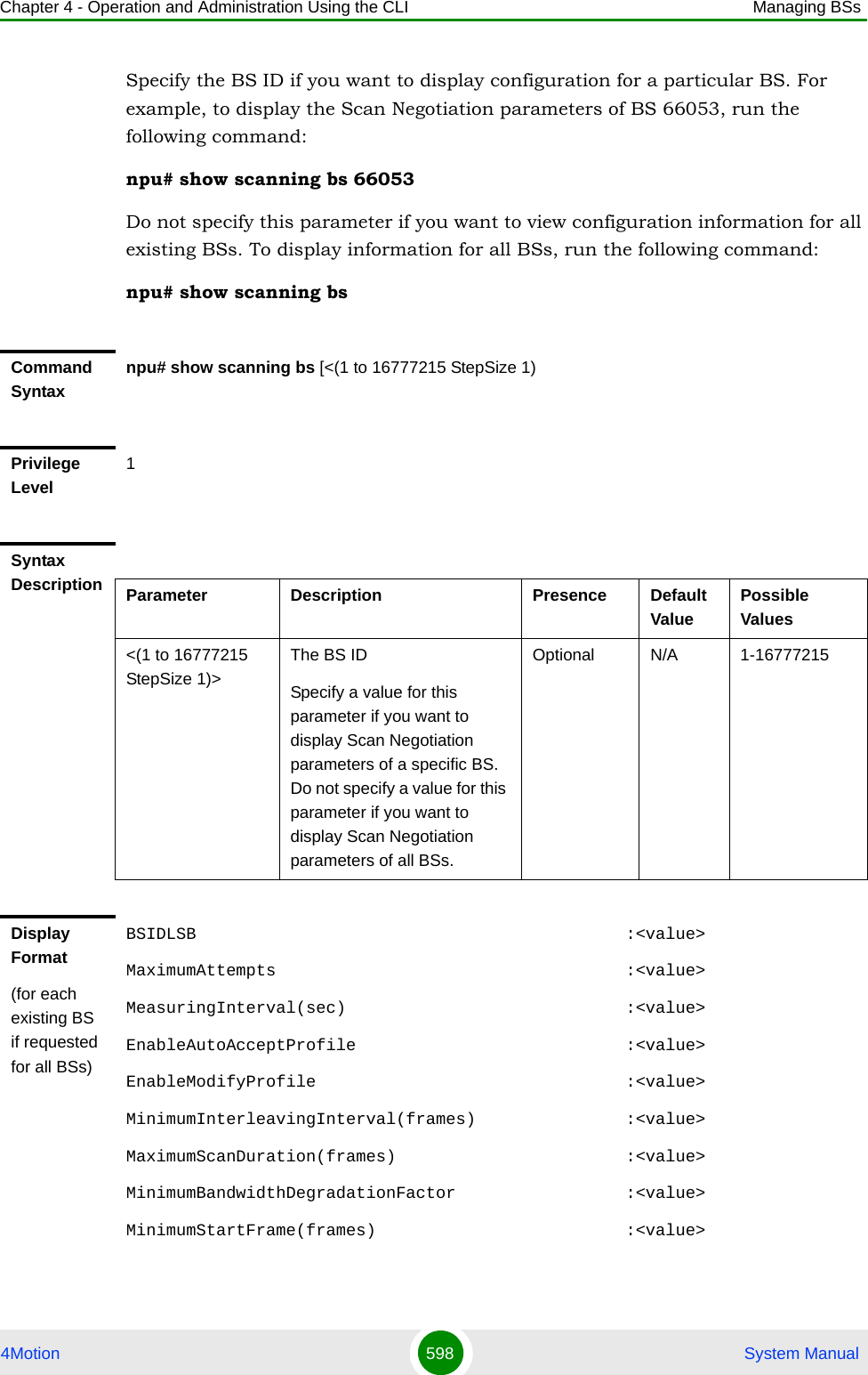
![Chapter 4 - Operation and Administration Using the CLI Managing BSs4Motion 599 System Manual4.8.12 Managing Handover Negotiation at SBS ParametersAfter enabling the BS configuration mode, you can execute the following tasks:Configure one or more of the Handover Negotiation at SBS parameters (refer to Section 4.8.12.1).Restore the default values of some or all of the Handover Negotiation at SBS parameters (refer to Section 4.8.12.2).You can display configuration information for the Handover Negotiation at SBS parameters of a selected or all existing BSs (refer to Section 4.8.12.3).4.8.12.1 Configuring Handover Negotiation at SBS ParametersFrom the BS configuration mode, run the following command:npu(config-bs-66053)# honegotiation-sbs [selectcoefficient <(0 to 10 StepSize 0.1)>] [max-tbs <(0 to 255 StepSize 1)>] [min-actiontime <(0 to 255 StepSize 1)>] [max-actiontime <(0 to 255 StepSize 1)>]Command ModesGlobal command modeTo configure the Handover Negotiation at SBS Parameters:IMPORTANTWhen creating a new BS, at least one of the Handover Negotiation at SBS parameters must be configured explicitly (even if configured to the default value).Command Syntaxnpu(config-bs-66053)# honegotiation-sbs [selectcoefficient <(0 to 10 StepSize 0.1)> ] [max-tbs <(0 to 255 StepSize 1)> ] [min-actiontime <(0 to 255 StepSize 1)> ] [max-actiontime <(0 to 255 StepSize 1)> ]Privilege Level10](https://usermanual.wiki/Alvarion-Technologies/BMAX-OR-25.Manual-3/User-Guide-1114031-Page-118.png)
![Chapter 4 - Operation and Administration Using the CLI Managing BSs4Motion 600 System Manual4.8.12.2 Restoring the Default Values of Handover Negotiation at SBS ParametersTo restore some or all of the Handover Negotiation at SBS parameters to their default values, run the following command:npu(config-bs-66053)# no honegotiation-sbs [selectcoefficient] [max-tbs] [min-actiontime] [max-actiontime]You can restore only some parameters to their default values by specifying only those parameters. For example, to restore only the max-tbs parameter to the default value, run the following command:npu(config-bs-66053)# no honegotiation-sbs max-tbsThis parameter will be restored to its default value, while the other parameters will remain unchanged.To restore all Handover Negotiation at SBS parameters to their default value, run the following command:npu(config-bs-66053)# no honegotiation-sbsSyntax Description Parameter Description Presence Default Value Possible Values[selectcoefficient <(0 to 10 StepSize 0.1)> ]The coefficient for selection of Target BSs for MOB_BSHO-RSPOptional 0.3 0 to 10 in steps of 0.1[max-tbs <(0 to 255 StepSize 1)> ]The naximum number of Target BSs to which to send HO-REQ message through the backbone.Optional 255 0 - 255[min-actiontime <(0 to 255 StepSize 1)> ]The minimum acceptable action time in the Serving BS (in frames)Optional 1 0 - 255[max-actiontime <(0 to 255 StepSize 1)> ]The maximum acceptable action time in the Serving BS (in frames)Optional 255 0 - 255Command Modesbs configuration mode](https://usermanual.wiki/Alvarion-Technologies/BMAX-OR-25.Manual-3/User-Guide-1114031-Page-119.png)
![Chapter 4 - Operation and Administration Using the CLI Managing BSs4Motion 601 System Manual4.8.12.3 Displaying Configuration Information for Handover Negotiation at SBS ParametersTo display configuration information for Handover Negotiation at SBS parameters, run the following command:npu# show honegotiation-sbs bs [<(1 to 16777215 StepSize 1)Specify the BS ID if you want to display configuration for a particular BS. For example, to display the Handover Negotiation at SBS parameters of BS 66053, run the following command:npu# show honegotiation-sbs bs 66053Do not specify this parameter if you want to view configuration information for all existing BSs. To display information for all BSs, run the following command:npu# show honegotiation-sbs bsNOTERefer to Section 4.8.12.1 for a description and default values of these parameters.Command Syntaxnpu(config-bs-66053)# no honegotiation-sbs [selectcoefficient ] [max-tbs ] [min-actiontime ] [max-actiontime ]Privilege Level10Command Modesbs configuration modeCommand Syntaxnpu# show honegotiation-sbs bs [<(1 to 16777215 StepSize 1)Privilege Level1](https://usermanual.wiki/Alvarion-Technologies/BMAX-OR-25.Manual-3/User-Guide-1114031-Page-120.png)
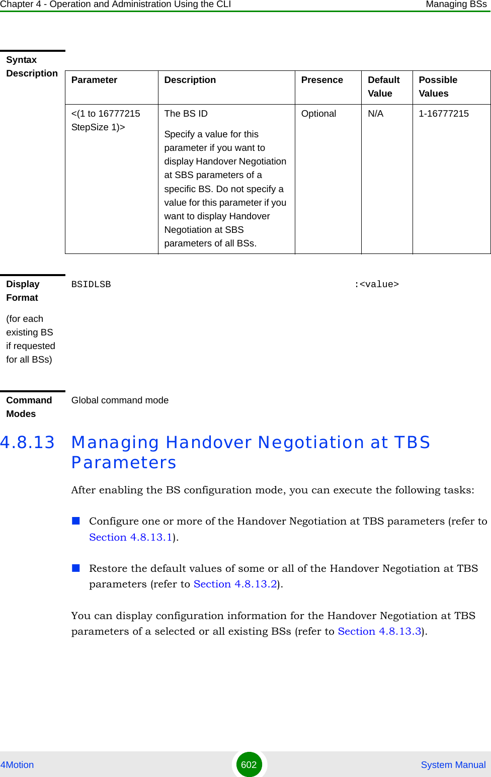
![Chapter 4 - Operation and Administration Using the CLI Managing BSs4Motion 603 System Manual4.8.13.1 Configuring Handover Negotiation at TBS ParametersFrom the BS configuration mode, run the following command:npu(config-bs-66053)# honegotiation-tbs [defaultactiontime <(0 to 255 StepSize 1)>] [fastrangingalloc <(0 to 255 StepSize 1)>]To configure the Handover Negotiation at TBS Parameters:IMPORTANTWhen creating a new BS, at least one of the Handover Negotiation at TBS parameters must be configured explicitly (even if configured to the default value).Command Syntaxnpu(config-bs-66053)# honegotiation-tbs [defaultactiontime <(0 to 255 StepSize 1)> ] [fastrangingalloc <(0 to 255 StepSize 1)> ]Privilege Level10Syntax Description Parameter Description Presence Default Value Possible Valuesdefaultactiontime <(0 to 255 StepSize 1)>The number of frames until allocation of non-contention based ranging opportunity at target BS.Optional 3 0 - 255fastrangingalloc <(0 to 255 StepSize 1)>The number of consecutive fast ranging opportunities the target BS will allocate to an incoming HO MS.Optional 2 0 - 255Command Modesbs configuration mode](https://usermanual.wiki/Alvarion-Technologies/BMAX-OR-25.Manual-3/User-Guide-1114031-Page-122.png)
![Chapter 4 - Operation and Administration Using the CLI Managing BSs4Motion 604 System Manual4.8.13.2 Restoring the Default Values of Handover Negotiation at TBS ParametersTo restore some or all of the Handover Negotiation at TBS parameters to their default values, run the following command:npu(config-bs-66053)# no honegotiation-tbs [defaultactiontime] [fastrangingalloc]You can restore only one parameter to the default values by specifying only that parameters. For example, to restore only the fastrangingalloc parameter to the default value, run the following command:npu(config-bs-66053)# no honegotiation-tbs fastrangingallocThis parameter will be restored to its default value, while the other parameter will remain unchanged.To restore all Handover Negotiation at TBS parameters to their default value, run the following command:npu(config-bs-66053)# no honegotiation-tbs4.8.13.3 Displaying Configuration Information for Handover Negotiation at TBS ParametersTo display configuration information for Handover Negotiation at TBS parameters, run the following command:npu# show honegotiation-tbs bs [<(1 to 16777215 StepSize 1)NOTERefer to Section 4.8.13.1 for a description and default values of these parameters.Command Syntaxnpu(config-bs-66053)# no honegotiation-stbs [defaultactiontime ] [fastrangingalloc ]Privilege Level10Command Modesbs configuration mode](https://usermanual.wiki/Alvarion-Technologies/BMAX-OR-25.Manual-3/User-Guide-1114031-Page-123.png)
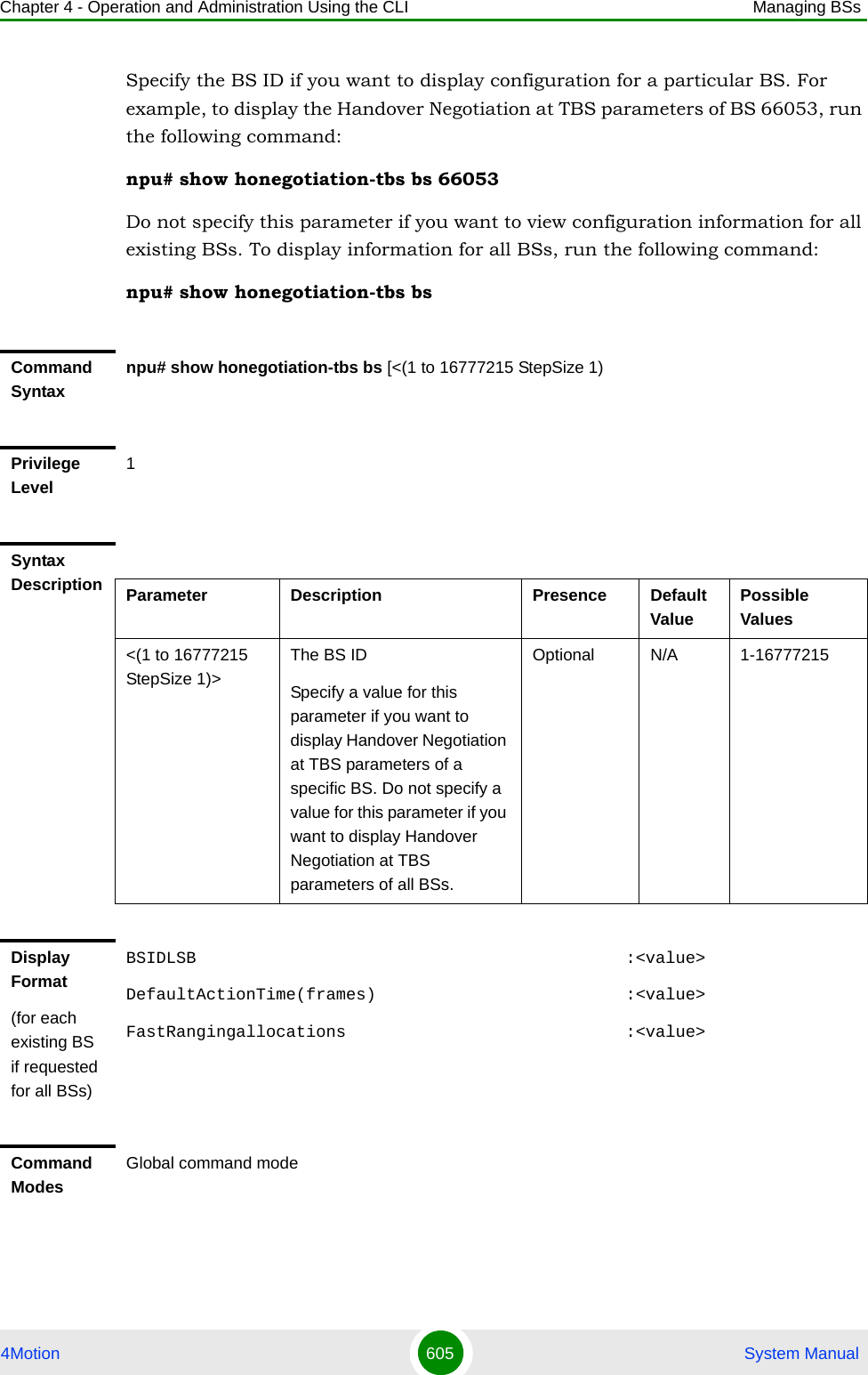
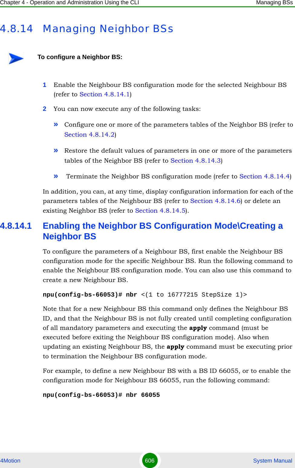
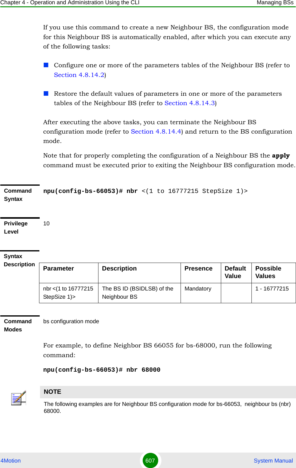
![Chapter 4 - Operation and Administration Using the CLI Managing BSs4Motion 608 System Manual4.8.14.2 Configuring Neighbor BS ParametersAfter enabling the Neighbor BS configuration mode you can configure the following parameters tables:General (refer to Section 4.8.14.2.1)Required C/N Level (refer to Section 4.8.14.2.2)Trigger Setup (refer to Section 4.8.14.2.3)Triggers (refer to Section 4.8.14.2.4)4.8.14.2.1 Configuring General Neighbor BS ParametersThe General Neighbor BS Parameters table enables defining the general parameters of the Neighbor BS.To configure the General Neighbor BS parameters, run the following command:npu(config-bs-66053-nbr-68000)# general [syncind {unsynchronized | timeSynchronized | timeAndFrequencySynchronized}] [eirp <(-128 to 127 StepSize 1)>] [srvcsupport <hex-string>] [bw {fiveMHz | tenMHz | sevenMHz}] [feedbackzone-permbase <(0 to 69 StepSize 1)>] [ucd-configchangecount <(0 to 255 StepSize 1)>] [dcd-configchangecount <(0 to 255 StepSize 1)>] [eirx-pir-max <(-140 to -40 StepSize 1)>] [frequency <(2302.5 to 2357.5 StepSize 0.125) | (2498.5 to 2687.5 StepSize 0.125) | (3402.5 to 3597.5 StepSize 0.125) | (3602.5 to 3797.5 StepSize 0.125)>] [restartcount <(0 to 255 StepSize 1)>] [preamble-idx <(0 to 113 StepSize 1)>] IMPORTANTAfter completing the Neighbour BS configuration,do not forget to execute the apply command before exiting the Neighbour BS configuration mode:npu(config-bs-66053-nbr-68000)# applyIMPORTANTWhen creating a new Neighbour BS, all mandatory Neighbour BS General parameters must be configured.](https://usermanual.wiki/Alvarion-Technologies/BMAX-OR-25.Manual-3/User-Guide-1114031-Page-127.png)
![Chapter 4 - Operation and Administration Using the CLI Managing BSs4Motion 609 System ManualCommand Syntaxnpu(config-bs-66053-nbr-68000)# general [syncind {unsynchronized | timeSynchronized | timeAndFrequencySynchronized} ] [eirp <(-128 to 127 StepSize 1)> ] [srvcsupport <hex-string>] [bw {fiveMHz | tenMHz | sevenMHz} ] [feedbackzone-permbase <(0 to 69 StepSize 1)> ] [ucd-configchangecount <(0 to 255 StepSize 1)>] [dcd-configchangecount <(0 to 255 StepSize 1)> ] [eirx-pir-max <(-140 to -40 StepSize 1)> ] [frequency <(2302.5 to 2357.5 StepSize 0.125) | (2498.5 to 2687.5 StepSize 0.125) | (3402.5 to 3597.5 StepSize 0.125) | (3602.5 to 3797.5 StepSize 0.125)> ] [restartcount <(0 to 255 StepSize 1)>] [preamble-idx <(0 to 113 StepSize 1)> ] Privilege Level10Syntax Description Parameter Description Presence Default Value Possible Values[syncind {unsynchronized | timeSynchronized | timeAndFrequencySynchronized} ]Time/Frequency synchronization indicator.In the current release should always be set to timeAndFrequencySynchronized.Optional timeAndFrequencySynchronizedunsynchronizedtimeSynchronizedtimeAndFrequencySynchronized[eirp <(-128 to 127 StepSize 1)> ]Neighbour BS EIRP Mandatory When creating a new Neighbour BS.N/A -128 to 127](https://usermanual.wiki/Alvarion-Technologies/BMAX-OR-25.Manual-3/User-Guide-1114031-Page-128.png)
![Chapter 4 - Operation and Administration Using the CLI Managing BSs4Motion 610 System Manual[srvcsupport <hex-string>] Scheduling Service Support. Two hexadeximal digits that can be presented as 8 bits where tbits 5-7 are always 0. Bits 0-4 indicate whether specific services are supported, where a value of 1 means that the service is supported: UGS (0), RT-PS(1), NRT-PS(2), BE(3), ERT-PS(4).Should be taken from the displayed information for Handover Control (hoctrl) in the relevant BS (see Section 4.8.23.3.Optional c8(11001000, meaning that the BS supports UGS, RT-PS and ERT-PS scheduling services).Two hexadecimal digits.[bw {fiveMHz | tenMHz | sevenMHz} ]The bandwidth of neighbour BS.Should be taken from Baseband bandwidth parameter of the relevant BS (see Section 4.8.18.2)Mandatory When creating a new Neighbour BS.N/A fiveMHztenMHzsevenMHz[feedbackzone-permbase <(0 to 69 StepSize 1)> ]The first uplink zone permutation base of the neighbor BS.In current release this equals the feedback zone permutation base (see Section 4.8.19.5.8)Mandatory When creating a new Neighbour BS.N/A 0 - 69[ucd-configchangecount <(0 to 255 StepSize 1)>]UCD configuration change count of neighbor BSShould be taken from displayed UCD information for the relevant BS (see Section 4.8.15.3Mandatory When creating a new Neighbour BS.N/A 0 - 255](https://usermanual.wiki/Alvarion-Technologies/BMAX-OR-25.Manual-3/User-Guide-1114031-Page-129.png)
![Chapter 4 - Operation and Administration Using the CLI Managing BSs4Motion 611 System Manual[dcd-configchangecount <(0 to 255 StepSize 1)> ] DCD configuration change count of neighbor BSShould be taken from displayed DCD information for the relevant BS (see Section 4.8.16.3Mandatory When creating a new Neighbour BS.N/A 0 - 255eirx-pir-max <(-140 to -40 StepSize 1)>The required effective isotropic received power at the Neighbor BS for Initial ranging, in dBm.Should be taken from Power Control maxeirxp (see Section 4.8.6.2.2)Optional -124 -140 to -40[frequency <(2302.5 to 2357.5 StepSize 0.125) | (2498.5 to 2687.5 StepSize 0.125) | (3402.5 to 3597.5 StepSize 0.125) | (3602.5 to 3797.5 StepSize 0.125)> ]Downlink center frequency of neighbor BS.Should be taken from RF frequency parameter of the relevant BS (see Section 4.8.17.2)Mandatory When creating a new Neighbour BS.N/A 2302.5 to 2357.5 in steps of 0.125)2498.5 to 2687.5 in steps of 0.1253402.5 to 3597.5 in steps of 0.1253602.5 to 3797.5 in steps of 0.125restartcount <(0 to 255 StepSize 1)> ]This value is incremented by one whenever the neighbor BS restarts.Should be taken from displayed DCD information for the relevant BS (see Section 4.8.16.3Mandatory When creating a new Neighbour BS.N/A 0 - 255](https://usermanual.wiki/Alvarion-Technologies/BMAX-OR-25.Manual-3/User-Guide-1114031-Page-130.png)
![Chapter 4 - Operation and Administration Using the CLI Managing BSs4Motion 612 System Manual4.8.14.2.2 Configuring the Neighbor BS Required C/N Level ParametersThe Neighbor BS Required C/N Levels table enables defining the Carrier to Noise Ratios required for various types of transmissions. The configured values should be the same as those defined for the applicable Power Control Required C/N Level parameters (see Section 4.8.6.5.3) in the neighbor BS.To configure the Neighbor BS Required C/N Levels, run the following command:npu(config-bs-66053-nbr-68000)# requiredcnr [ack <(-20 to 50 StepSize 1)>] [cqi <(-20 to 50 StepSize 1)>] [cdma <(-20 to 50 StepSize 1)>] [qpsk-1by2 <(-20 to 50 StepSize 1)>] [qpsk-3by4 <(-20 to 50 StepSize 1)>] [qam16-1by2 <(-20 to 50 StepSize 1)>] [qam16-3by4 <(-20 to 50 StepSize 1)>] [qam64-1by2 <(-20 to 50 StepSize 1)>] [qam64-2by3 <(-20 to 50 StepSize 1)>] [qam64-3by4 <(-20 to 50 StepSize 1)>] [qam64-5by6 <(-20 to 50 StepSize 1)>][preamble-idx <(0 to 113 StepSize 1)> ]Neighbour BS Preamble Index.Should be the same as preamble-idx in displayed information of Airframe General parameters of the relevant BS (see Section 4.8.19.5.1Mandatory When creating a new Neighbour BS.N/A 0 - 113Command Modesbs neighbour bs configuration mode IMPORTANTWhen creating a new Neighbour BS, at least one of the Neighbour BS Required C/N Level parameters must be configured explicitly (even if configured to the default value).Command Syntaxnpu(config-bs-66053-nbr-68000)# requiredcnr [ack <(-20 to 50 StepSize 1)> ] [cqi <(-20 to 50 StepSize 1)> ] [cdma <(-20 to 50 StepSize 1)> ] [qpsk-1by2 <(-20 to 50 StepSize 1)> ] [qpsk-3by4 <(-20 to 50 StepSize 1)> ] [qam16-1by2 <(-20 to 50 StepSize 1)> ] [qam16-3by4 <(-20 to 50 StepSize 1)> ] [qam64-1by2 <(-20 to 50 StepSize 1)> ] [qam64-2by3 <(-20 to 50 StepSize 1)> ] [qam64-3by4 <(-20 to 50 StepSize 1)> ] [qam64-5by6 <(-20 to 50 StepSize 1)> ]](https://usermanual.wiki/Alvarion-Technologies/BMAX-OR-25.Manual-3/User-Guide-1114031-Page-131.png)
![Chapter 4 - Operation and Administration Using the CLI Managing BSs4Motion 613 System ManualPrivilege Level10Syntax Description Parameter Description Presence Default Value Possible Values[ack <(-20 to 50 StepSize 1)> ]The C/N in dB required for sending ACK, reported by the Neighbour BS to the MS for power control purposes.Optional 7 -20 to 50[cqi <(-20 to 50 StepSize 1)> ]The C/N in dB required for sending CQI, reported by the Neighbour BS to the MS for power control purposes.Optional 0 -20 to 50 [cdma <(-20 to 50 StepSize 1)> ]The C/N in dB required for transmitting CDMA, reported by the Neighbour BS to the MS for power control purposes.Optional 0 -20 to 50[qpsk-1by2 <(-20 to 50 StepSize 1)> ]The C/N in dB required for transmitting using QPSK 1/2, reported by the Neighbour BS to the MS for power control purposes.Optional 14 -20 to 50[qpsk-3by4<(-20 to 50 StepSize 1)> ]The C/N in dB required for transmitting using QPSK 3/4, reported by the Neighbour BS to the MS for power control purposes.Optional 16 -20 to 50[qam16-1by2 <(-20 to 50 StepSize 1)> ]The C/N in dB required for transmitting using 16QAM 1/2, reported by the Neighbour BS to the MS for power control purposes.Optional 18 -20 to 50[qam16-3by4 <(-20 to 50 StepSize 1)> ]The C/N in dB required for transmitting using 16QAM 3/4, reported by the Neighbour BS to the MS for power control purposes.Optional 22 -20 to 50](https://usermanual.wiki/Alvarion-Technologies/BMAX-OR-25.Manual-3/User-Guide-1114031-Page-132.png)
![Chapter 4 - Operation and Administration Using the CLI Managing BSs4Motion 614 System Manual4.8.14.2.3 Configuring Trigger Setup ParametersTo configure the Neighbor BS Trigger Setup parameters, run the following command:npu(config-bs-66053-nbr-68000)# triggersetup [hysteresismargin <(0 to 255 StepSize 1)>] [timetotrigger <(0 to 255 StepSize 1)>] [avgduration-rssi <(0 to 255 StepSize 1)>] [avgduration-cinr <(0 to 255 StepSize 1)>] [avgduration-rtd <(0 to 255 StepSize 1)>]The configured values should be the same as those defined for the applicable Trigger Setup parameters (see Section 4.8.10.3) in the neighbor BS. qam64-1by2 <(-20 to 50 StepSize 1)> ]The C/N in dB required for transmitting using 64QAM 1/2, reported by the Neighbour BS to the MS for power control purposes.Optional 23 -20 to 50[qam64-2by3 <(-20 to 50 StepSize 1)> ]The C/N in dB required for transmitting using 64QAM 2/3, reported by the Neighbour BS to the MS for power control purposes.Optional 23 -20 to 50[qam64-3by4 <(-20 to 50 StepSize 1)> ]The C/N in dB required for transmitting using 64QAM 3/4, reported by the Neighbour BS to the MS for power control purposes.Optional 23 -20 to 50[qam64-5by6 <(-20 to 50 StepSize 1)> ]he C/N in dB required for transmitting using 64QAM 5/6, reported by the Neighbour BS to the MS for power control purposes.Optional 23 -20 to 50Command Modesbs neighbour bs configuration mode IMPORTANTWhen creating a new Neighbour BS, at least one of the Neighbour BS Trigger Setup parameters must be configured explicitly (even if configured to the default value).](https://usermanual.wiki/Alvarion-Technologies/BMAX-OR-25.Manual-3/User-Guide-1114031-Page-133.png)
![Chapter 4 - Operation and Administration Using the CLI Managing BSs4Motion 615 System Manual4.8.14.2.4 Configuring Neighbor BS Triggers ParametersTo configure the Neighbor BS Triggers parameters, run the following command:npu(config-bs-66053-nbr-68000)# triggers-<trigger-name> <trigger-range>Each Trigger is configured separately. This is the general structure of the command.The configured trigger names and values should be the same as those defined for the applicable Triggers parameters (see Section 4.8.9.2) in the neighbor BS. Command Syntaxnpu(config-bs-66053-nbr-68000)# triggersetup [hysteresismargin <(0 to 255 StepSize 1)> ] [timetotrigger <(0 to 255 StepSize 1)> ] [avgduration-rssi <(0 to 255 StepSize 1)> ] [avgduration-cinr <(0 to 255 StepSize 1)> ] [avgduration-rtd <(0 to 255 StepSize 1)> ]Privilege Level10Syntax Description Refer to Section 4.8.10.1Command Modesbs neighbour bs configuration modeIMPORTANTWhen creating a new Neighbour BS, at least one of the Neighbour BS Trigges parameters must be configured.Command Syntaxnpu(config-bs-66053-nbr-68000)# triggers-<trigger-name> <trigger-range>Privilege Level10Syntax Description Parameter Description Presence Default Value Possible Values](https://usermanual.wiki/Alvarion-Technologies/BMAX-OR-25.Manual-3/User-Guide-1114031-Page-134.png)
![Chapter 4 - Operation and Administration Using the CLI Managing BSs4Motion 616 System Manual4.8.14.3 Restoring Default Values for Neighbor BS Configuration ParametersAfter enabling the Neighbor BS configuration mode you can restore the default values for non-mandatory parameters in the following parameters tables:General (refer to Section 4.8.14.3.1)Required C/N Level (refer to Section 4.8.14.3.2)Trigger Setup (refer to Section 4.8.14.3.3)4.8.14.3.1 Restoring the Default Values of Neighbor BS General ParametersTo restore one or all of the Neighbor BS non-mandatory General parameters to their default values, run the following command:npu(config-bs-66053-nbr-68000)# no general [syncind] [srvcsupport] [eirx-pir-max]You can restore only some parameters to the default values by specifying only those parameters. For example, to restore only the syncind to the default value, run the following command:npu(config-bs-66053-nbr-68000)# no general syncindThe parameter will be restored to its default value, while the other parameters will remain unchanged.To restore all non-mandatory parameters to their default value, run the following command:npu(config-bs-66053-nbr-68000)# no general<trigger-name> The Trigger name. Mandatory N/A See Table 4-30<trigger-value> Defines the threshold value for the Trigger. Mandatory N/A See Table 4-30Command Modesbs neighbour bs configuration mode](https://usermanual.wiki/Alvarion-Technologies/BMAX-OR-25.Manual-3/User-Guide-1114031-Page-135.png)
![Chapter 4 - Operation and Administration Using the CLI Managing BSs4Motion 617 System Manual4.8.14.3.2 Restoring the Default Values of Neighbor BS Required C/N Level ParametersTo restore some or all of the Neighbor BS Required C/N Levels parameters to their default values, run the following command:npu(config-bs-66053-bs-68000)# no requiredcnr [ack] [cqi] [cdma] [qpsk-1by2] [qpsk-3by4] [qam16-1by2] [qam16-3by4] [qam64-1by2] [qam64-2by3] [qam64-3by4] [qam64-5by6]You can restore only some parameters to their default values by specifying only those parameter. For example, to restore only the ack and cqi parameters to the default values, run the following command:npu(config-bs-66053-nbr-68000)# no requiredcnr ack cqiThese parameters will be restored to their default value, while the other parameters will remain unchanged.To restore all Neighbor BS Required C/N Levels parameters to their default value, run the following command:npu(config-bs-66053-nbr-68000)# no requiredcnrNOTERefer to Section 4.8.14.2.1 for a description and default values of these parameters.Command Syntaxnpu(config-bs-66053-nbr-68000)# no general [syncind ] [srvcsupport][eirx-pir-max ]Privilege Level10Command Modesbs neighbour bs configuration modeNOTERefer to Section 4.8.14.2.2 for a description and default values of these parameters.Command Syntaxnpu(config-bs-66053-nbr-68000)# no requiredcnr [ack ] [cqi ] [cdma ] [qpsk-1by2 ] [qpsk-3by4 ] [qam16-1by2 ] [qam16-3by4 ] [qam64-1by2 ] [qam64-2by3 ] [qam64-3by4 ] [qam64-5by6 ]](https://usermanual.wiki/Alvarion-Technologies/BMAX-OR-25.Manual-3/User-Guide-1114031-Page-136.png)
![Chapter 4 - Operation and Administration Using the CLI Managing BSs4Motion 618 System Manual4.8.14.3.3 Restoring the Default Values of Neighbor BS Trigger Setup ParametersTo restore some or all of the Neighbor BS Trigger Setup parameters to their default values, run the following command:npu(config-bs-66053-nbr-68000)# no triggersetup [hysteresismargin] [timetotrigger] [avgduration-rssi] [avgduration-cinr] [avgduration-rtd]You can restore only some parameters to their default values by specifying only those parameters. For example, to restore only the hysteresismargin parameter to the default value, run the following command:npu(config-bs-66053-nbr-68000)# no triggersetup hysteresismarginThis parameter will be restored to its default value, while the other parameters will remain unchanged.To restore all Neighbor BS Trigger Setup parameters to their default value, run the following command:npu(config-bs-66053-nbr-68000)# no triggersetupPrivilege Level10Command Modesbs neighbour bs configuration modeNOTERefer to Section 4.8.14.2.3 for a description and default values of these parameters.Command Syntaxnpu(config-bs-66053-nbr-68000)# no triggersetup [hysteresismargin ] [timetotrigger ] [avgduration-rssi] [avgduration-cinr] [avgduration-rtd ]Privilege Level10Command Modesbs neighbour bs configuration mode](https://usermanual.wiki/Alvarion-Technologies/BMAX-OR-25.Manual-3/User-Guide-1114031-Page-137.png)
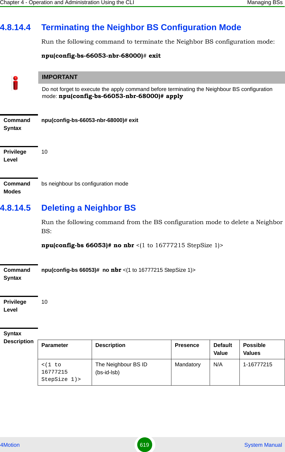
![Chapter 4 - Operation and Administration Using the CLI Managing BSs4Motion 620 System Manual4.8.14.6 Displaying Configuration Information for Neighbor BS ParametersYou can display the current configuration information for the following Neighbor BS parameters tables:General (refer to Section 4.8.14.6.1) Required C/N Level (refer to Section 4.8.14.6.2)Trigger Setup (refer to Section 4.8.14.6.3)Triggers (refer to Section 4.8.14.6.4)All (refer to Section 4.8.14.6.5)4.8.14.6.1 Displaying Configuration Information for Neighbor BS General ParametersTo display configuration for the Neighbor BS General parameters, run the following command:npu# show nbr-general bs [<(1 to 16777215 StepSize 1)> bs-id-lsb <(1 to 16777215 StepSize 1)>]Specify the BS ID and the Neighbor BS ID (bs-id-lsb) if you want to display configuration for a particular Neighbor BS in a particular BS. For example, to display the General parameters of Neighbor BS 68000 in BS 66503, run the following command:npu# show nbr-general bs 66053 bs-id-lsb 68000Do not specify these parameters if you want to view configuration information for all existing Neighbor BSs in all existing BSs. To display information for all Neighbor BSs in all BSs, run the following command:npu# show nbr-general bsCommand Modesbs configuration modeCommand Syntaxnpu# show nbr-general bs [<(1 to 16777215 StepSize 1)> bs-id-lsb <(1 to 16777215 StepSize 1)> ]](https://usermanual.wiki/Alvarion-Technologies/BMAX-OR-25.Manual-3/User-Guide-1114031-Page-139.png)
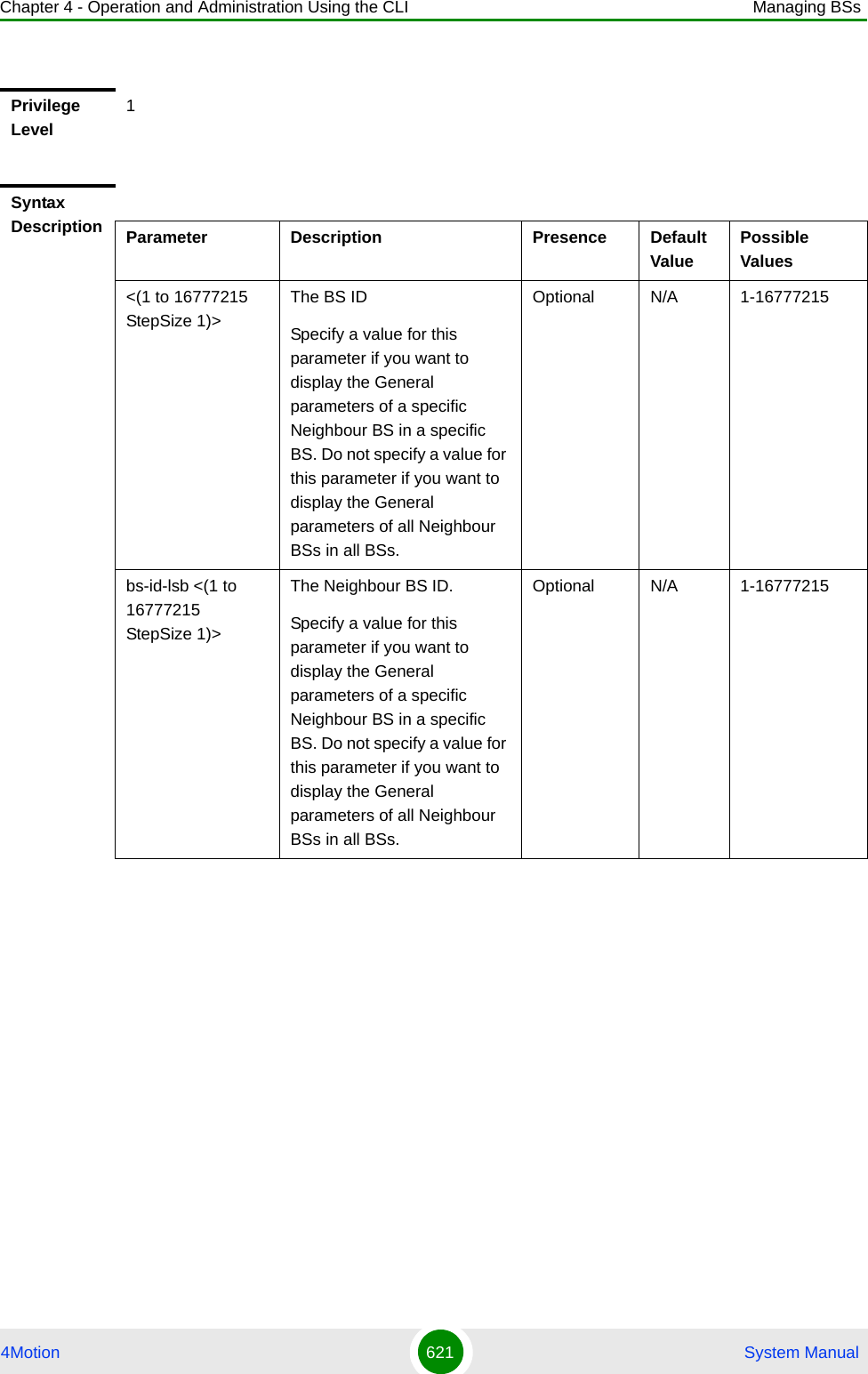
![Chapter 4 - Operation and Administration Using the CLI Managing BSs4Motion 622 System Manual4.8.14.6.2 Displaying Configuration Information for Neighbor BS Required C/N Level ParametersTo display configuration for the Neighbor BS Required C/N Level parameters, run the following command:npu# show nbr-requiredcnr bs [<(1 to 16777215 StepSize 1)> bs-id-lsb <(1 to 16777215 StepSize 1)>]Specify the BS ID and the Neighbor BS ID (bs-id-lsb) if you want to display configuration for a particular Neighbor BS in a particular BS. For example, to display the Required C/N Level parameters of Neighbor BS 68000 in BS 66503, run the following command:npu# show nbr-requiredcnr bs 66053 bs-id-lsb 68000Do not specify these parameters if you want to view configuration information for all existing Neighbor BSs in all existing BSs. To display information for all Neighbor BSs in all BSs, run the following command:npu# show nbr-requiredcnr bsDisplay Format(for each existing Neighbour BS in each of the existing BSs if requested for all)BSIDLSB :<value>NeighborBSIDLSB :<value>SynchronizationIndicator :<value>EIRP :<value>SchedulingServiceSupport :<value>Bandwidth(MHz) :<value>UplinkFeedbackZonePermutationBase :<value>UplinkDataZoneSub-ChannelsAllocated :<value>UCDConfigurationChangeCount :<value>DCDConfigurationChangeCount :<value>IsotropicRecPwrForInitialRanging :<value>CenterFrequency(MHz) :<value>RestartCount :<value>PreambleIndex :<value>Command ModesGlobal command mode](https://usermanual.wiki/Alvarion-Technologies/BMAX-OR-25.Manual-3/User-Guide-1114031-Page-141.png)
![Chapter 4 - Operation and Administration Using the CLI Managing BSs4Motion 623 System ManualCommand Syntaxnpu# show nbr-requiredcnr bs [<(1 to 16777215 StepSize 1)> bs-id-lsb <(1 to 16777215 StepSize 1)> ]Privilege Level1Syntax Description Parameter Description Presence Default ValuePossible Values<(1 to 16777215 StepSize 1)>The BS ID Specify a value for this parameter if you want to display the Required C/N Level parameters of a specific Neighbour BS in a specific BS. Do not specify a value for this parameter if you want to display the Required C/N Level parameters of all Neighbour BSs in all BSs.Optional N/A 1-16777215bs-id-lsb <(1 to 16777215 StepSize 1)> The Neighbour BS ID.Specify a value for this parameter if you want to display the Required C/N Level parameters of a specific Neighbour BS in a specific BS. Do not specify a value for this parameter if you want to display the Required C/N Level parameters of all Neighbour BSs in all BSs.Optional N/A 1-16777215](https://usermanual.wiki/Alvarion-Technologies/BMAX-OR-25.Manual-3/User-Guide-1114031-Page-142.png)
![Chapter 4 - Operation and Administration Using the CLI Managing BSs4Motion 624 System Manual4.8.14.6.3 Displaying Configuration Information for Neighbor BS Trigger Setup ParametersTo display configuration for the Neighbor BS Trigger Setup parameters, run the following command:npu# show nbr-triggersetup bs [<(1 to 16777215 StepSize 1)> bs-id-lsb <(1 to 16777215 StepSize 1)>]Specify the BS ID and the Neighbor BS ID (bs-id-lsb) if you want to display configuration for a particular Neighbor BS in a particular BS. For example, to display the Trigger Setup parameters of Neighbor BS 68000 in BS 66503, run the following command:npu# show nbr-triggersetup bs 66053 bs-id-lsb 68000Do not specify these parameters if you want to view configuration information for all existing Neighbor BSs in all existing BSs. To display information for all Neighbor BSs in all BSs, run the following command:npu# show nbr-triggersetup bsDisplay Format(for each existing Neighbour BS in each of the existing BSs if requested for all)BSIDLSB :<value>NeighborBSIDLSB :<value>RequiredCNRforACK :<value>RequiredCNRforCQI :<value>RequiredCNRforCDMA :<value>RequiredCNRforQPSK1/2 :<value>RequiredCNRforQPSK3/4 :<value>RequiredCNRfor16QAM1/2 :<value>RequiredCNRfor16QAM3/4 :<value>RequiredCNRfor64QAM1/2 :<value>RequiredCNRfor64QAM2/3 :<value>RequiredCNRfor64QAM3/4 :<value>RequiredCNRfor64QAM5/6 :<value>Command ModesGlobal command mode](https://usermanual.wiki/Alvarion-Technologies/BMAX-OR-25.Manual-3/User-Guide-1114031-Page-143.png)
![Chapter 4 - Operation and Administration Using the CLI Managing BSs4Motion 625 System ManualCommand Syntaxnpu# show nbr-triggersetup bs [<(1 to 16777215 StepSize 1)> bs-id-lsb <(1 to 16777215 StepSize 1)> ]Privilege Level1Syntax Description Parameter Description Presence Default ValuePossible Values<(1 to 16777215 StepSize 1)>The BS ID Specify a value for this parameter if you want to display the Trigger Setup parameters of a specific Neighbour BS in a specific BS. Do not specify a value for this parameter if you want to display the Trigger Setup parameters of all Neighbour BSs in all BSs.Optional N/A 1-16777215bs-id-lsb <(1 to 16777215 StepSize 1)> The Neighbour BS ID.Specify a value for this parameter if you want to display the Trigger Setup parameters of a specific Neighbour BS in a specific BS. Do not specify a value for this parameter if you want to display the Trigger Setup parameters of all Neighbour BSs in all BSs.Optional N/A 1-16777215](https://usermanual.wiki/Alvarion-Technologies/BMAX-OR-25.Manual-3/User-Guide-1114031-Page-144.png)
![Chapter 4 - Operation and Administration Using the CLI Managing BSs4Motion 626 System Manual4.8.14.6.4 Displaying Configuration Information for Neighbor BS Triggers ParametersTo display configuration information for Neighbor BS Triggers parameters, run the following command:npu# show nbr-triggers bs [<(1 to 16777215 StepSize 1)> bs-id-lsb <(1 to 16777215 StepSize 1)> TrigName {scnReqCinrMin | scnReqRssiMin | scnReqRtdMax | scnRepCinrMaxNbs | scnRepRssiMaxNbs | scnRepCinrMargin | scnRepRssiMargin | scnRepRtdMax | scnRepCinrMinSbs | scnRepRssiMinSbs | hoReqCinrMaxNbs | hoReqRssiMaxNbs | hoReqCinrMargin | hoReqRssiMargin | hoReqRtdMax | hoReqCinrMinSbs | hoReqRssiMinSbs}]Specify the BS ID, Neighbour BS ID (bs-id-lsb) and Trigger name if you want to display configuration for a particular Trigger. For example, to display the scnReqCinrMin parameters of BS Neighbour 68000 in BS 66053, run the following command:npu# show nbr-triggers bs 66053 bs-id-lsb 68000 TrigName scnReqCinrMinDo not specify these parameters if you want to view configuration information for all existing Neighbour BSs in all BSs. To display information for all Neighbour BSs in all BSs, run the following command:npu# show nbr-triggers bsDisplay Format(for each existing Neighbour BS in each of the existing BSs if requested for all)BSIDLSB :<value>NeighborBSIDLSB :<value>HysteresisMargin(dB) :<value>TimetoTrigger(msec) :<value>AverageDurationofDefaultRSSI(msec) :<value>AverageDurationofDefaultCINR(msec) :<value>AverageDurationofDefaultRTD(msec) :<value>Command ModesGlobal command modeCommand Syntaxnpu# show nbr-triggers bs [<(1 to 16777215 StepSize 1)> bs-id-lsb <(1 to 16777215 StepSize 1)> TrigName {scnReqCinrMin | scnReqRssiMin | scnReqRtdMax | hoReqCinrMaxNbs | hoReqRssiMaxNbs | hoReqCinrMargin | hoReqRssiMargin | hoReqRtdMax | hoReqCinrMinSbs | hoReqRssiMinSbs} ]](https://usermanual.wiki/Alvarion-Technologies/BMAX-OR-25.Manual-3/User-Guide-1114031-Page-145.png)
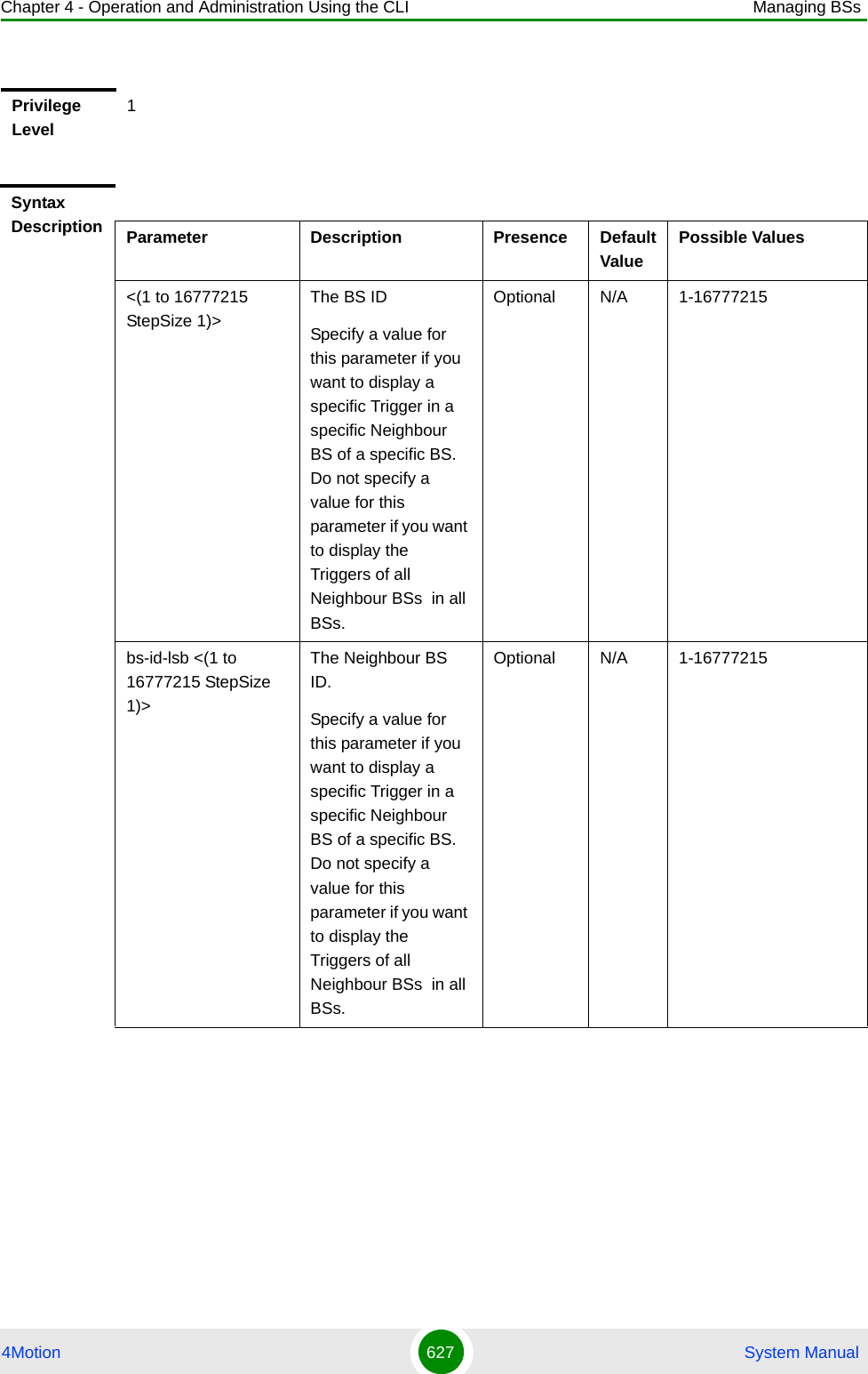
![Chapter 4 - Operation and Administration Using the CLI Managing BSs4Motion 628 System Manual4.8.14.6.5 Displaying Configuration Information for All Neighbour BS ParametersTo display configuration for the all Neighbour BS parameters, run the following command:npu# show nbr-all bs [<(1 to 16777215 StepSize 1)> bs-id-lsb <(1 to 16777215 StepSize 1)>]Specify the BS ID and the Neighbour BS ID (bs-id-lsb) if you want to display configuration for a particular Neighbour BS in a particular BS. For example, to display all parameters of Neighbour BS 68000 in BS 66503, run the following command:npu# show nbr-all bs 66053 bs-id-lsb 68000Do not specify these parameters if you want to view configuration information for all existing Neighbour BSs in all existing BSs. To display information for all Neighbour BSs in all BSs, run the following command:TrigName {scnReqCinrMin | scnReqRssiMin | scnReqRtdMax | hoReqCinrMaxNbs | hoReqRssiMaxNbs | hoReqCinrMargin | hoReqRssiMargin | hoReqRtdMax | hoReqCinrMinSbs | hoReqRssiMinSbs} ]The Trigger name Specify only if you want to display a specific Trigger of a specific Neighbour BS in a specific BS. Do not specify if you want to display all Triggers parameters of all Neighbour BSs in all BSsscnReqCinrMinscnReqRssiMinscnReqRtdMaxhoReqCinrMaxNbshoReqRssiMaxNbshoReqCinrMarginhoReqRssiMarginhoReqRtdMaxhoReqCinrMinSbshoReqRssiMinSbs}Display Format(for a selected Trigger)BSIDLSB :<value>BSIDLSB :value>scnReqCinrMin :value>Command ModesGlobal command mode](https://usermanual.wiki/Alvarion-Technologies/BMAX-OR-25.Manual-3/User-Guide-1114031-Page-147.png)
![Chapter 4 - Operation and Administration Using the CLI Managing BSs4Motion 629 System Manualnpu# show nbr-all bs4.8.15 Managing UCD ParametersAfter enabling the BS configuration mode, you can execute the following tasks:Command Syntaxnpu# show nbr-all bs [<(1 to 16777215 StepSize 1)> bs-id-lsb <(1 to 16777215 StepSize 1)> ]Privilege Level10Syntax Description Parameter Description Presence Default ValuePossible Values<(1 to 16777215 StepSize 1)>The BS ID Specify a value for this parameter if you want to display the Trigger Setup parameters of a specific Neighbour BS in a specific BS. Do not specify a value for this parameter if you want to display the Trigger Setup parameters of all Neighbour BSs in all BSs.Optional N/A 1-16777215bs-id-lsb <(1 to 16777215 StepSize 1)> The Neighbour BS ID.Specify a value for this parameter if you want to display the Trigger Setup parameters of a specific Neighbour BS in a specific BS. Do not specify a value for this parameter if you want to display the Trigger Setup parameters of all Neighbour BSs in all BSs.Optional N/A 1-16777215Command ModesGlobal command mode](https://usermanual.wiki/Alvarion-Technologies/BMAX-OR-25.Manual-3/User-Guide-1114031-Page-148.png)
![Chapter 4 - Operation and Administration Using the CLI Managing BSs4Motion 630 System ManualConfigure one or more of the UCD parameters (refer to Section 4.8.15.1).Restore the default values of some or all of the UCD parameters (refer to Section 4.8.15.2).You can display configuration and status information for the UCD parameters of a selected or all existing BSs (refer to Section 4.8.15.3).4.8.15.1 Configuring UCD ParametersFrom the BS configuration mode, run the following command:npu(config-bs-66053)# ucd [interval <(1 to 10000 StepSize 1)>] [transition <(20 to 1000 StepSize 1)>]To configure the UCD Parameters:Command Syntaxnpu(config-bs-66053)# ucd [interval <(1 to 10000 StepSize 1)> ] [transition <(20 to 1000 StepSize 1)> ]Privilege Level10Syntax Description Parameter Description Presence Default Value Possible Values[interval <(1 to 10000 StepSize 1)> ]The time in milliseconds between transmission of Uplink Channel Descriptor messages.Optional 1000 1 - 10000](https://usermanual.wiki/Alvarion-Technologies/BMAX-OR-25.Manual-3/User-Guide-1114031-Page-149.png)
![Chapter 4 - Operation and Administration Using the CLI Managing BSs4Motion 631 System Manual4.8.15.2 Restoring the Default Values of UCD ParametersTo restore the default values of some or all of the UCD parameters, run the following command:npu(config-bs-66053)# no ucd [interval] [transition]You can restore only one parameter to the default values by specifying only that parameters. For example, to restore only the interval parameter to the default value, run the following command:npu(config-bs-66053)# no ucd intervalThis parameter will be restored to its default value, while the other parameter will remain unchanged.To restore all UCD parameters to their default value, run the following command:npu(config-bs-66053)# no ucd[transition <(20 to 1000 StepSize 1)> ]The number of frames from the end of the frame carrying the Uplink Channel Descriptor message that the BS should wait after repeating an Uplink Channel Descriptor message with an increment of the configuration change count before issuing a UL-MAP message referring to Uplink_Burst_ProfilesOptional 100 20 - 1000Command Modesbs configuration modeIMPORTANTWhen creating a new BS, at least one of the UCD parameters must be configured explicitly (even if configured to the default value).NOTERefer to Section 4.8.15.1 for a description and default values of these parameters.](https://usermanual.wiki/Alvarion-Technologies/BMAX-OR-25.Manual-3/User-Guide-1114031-Page-150.png)
![Chapter 4 - Operation and Administration Using the CLI Managing BSs4Motion 632 System Manual4.8.15.3 Displaying Configuration and Status Information for UCD ParametersTo display configuration and status information of UCD parameters, run the following command:npu# show ucd bs [<(1 to 16777215 StepSize 1)Specify the BS ID if you want to display information for a particular BS. For example, to display the UCD parameters of BS 66053, run the following command:npu# show ucd bs 66053Do not specify this parameter if you want to view information for all existing BSs. To display information for all BSs, run the following command:npu# show ucd bsCommand Syntaxnpu(config-bs-66053)# no ucd [interval ] [transition ]Privilege Level10Command Modesbs configuration modeCommand Syntaxnpu# show ucd bs [<(1 to 16777215 StepSize 1)Privilege Level1](https://usermanual.wiki/Alvarion-Technologies/BMAX-OR-25.Manual-3/User-Guide-1114031-Page-151.png)
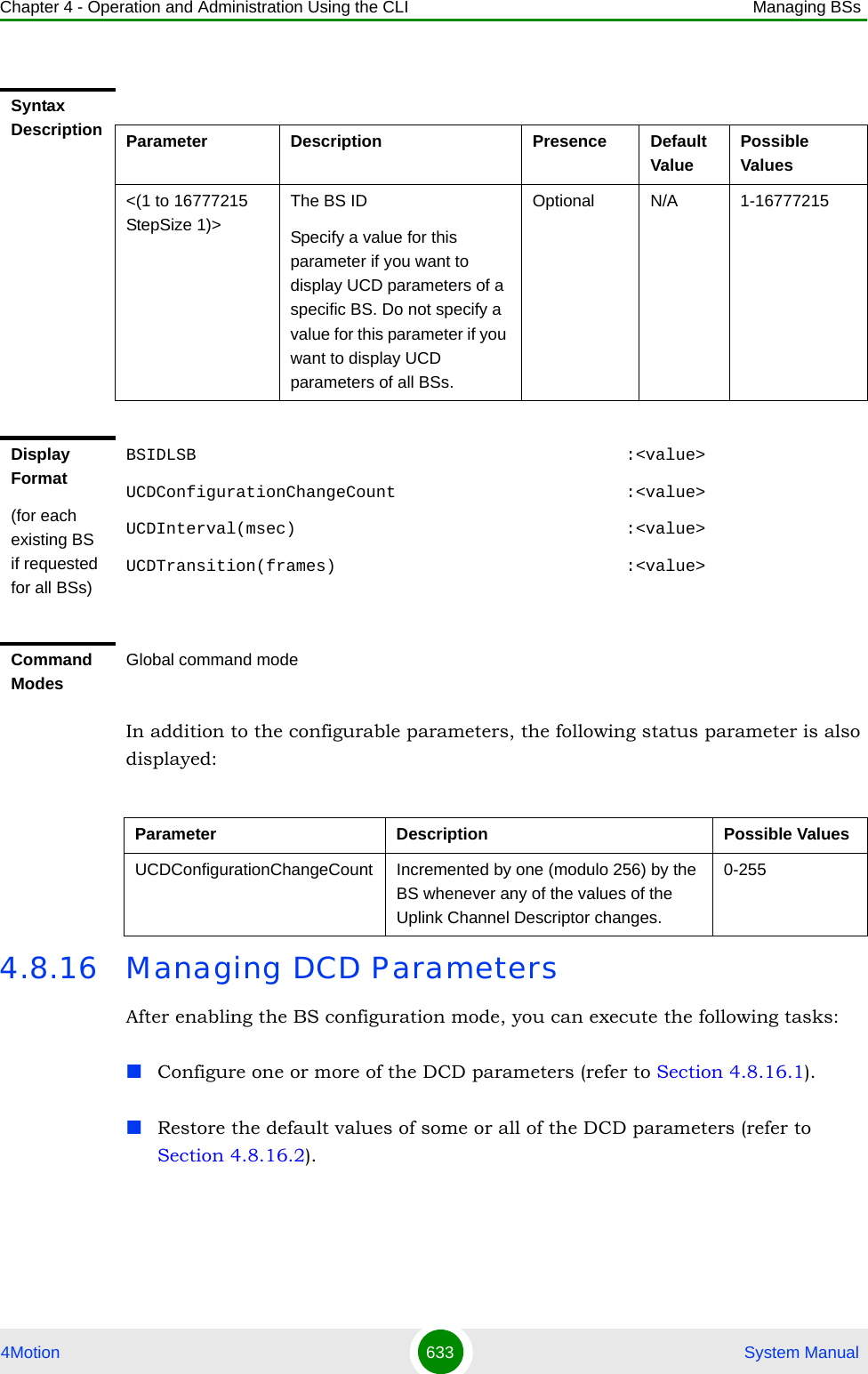
![Chapter 4 - Operation and Administration Using the CLI Managing BSs4Motion 634 System ManualYou can display configuration and status information for the DCD parameters of a selected or all existing BSs (refer to Section 4.8.16.3).4.8.16.1 Configuring DCD ParametersFrom the BS configuration mode, run the following command:npu(config-bs-66053)# dcd [interval <(1 to 10000 StepSize 1)>] [transition <(20 to 1000 StepSize 1)>]To configure the DCD Parameters:Command Syntaxnpu(config-bs-66053)# dcd [interval <(1 to 10000 StepSize 1)> ] [transition <(20 to 1000 StepSize 1)> ]Privilege Level10Syntax Description Parameter Description Presence Default Value Possible Values[interval <(1 to 10000 StepSize 1)> ]The time in milliseconds between transmission of Downlink Channel Descriptor messages.Optional 1000 1 - 10000[transition <(20 to 1000 StepSize 1)> ]The number of frames from the end of the frame carrying the Downlink Channel Descriptor message that the BS should wait after repeating a Downlink Channel Descriptor message with an increment of the configuration change count before issuing a DL-MAP message referring to Downlink_Burst_ProfilesOptional 100 20 - 1000](https://usermanual.wiki/Alvarion-Technologies/BMAX-OR-25.Manual-3/User-Guide-1114031-Page-153.png)
![Chapter 4 - Operation and Administration Using the CLI Managing BSs4Motion 635 System Manual4.8.16.2 Restoring the Default Values of DCD ParametersTo restore the default values of some or all of the DCD parameters, run the following command:npu(config-bs-66053)# no dcd [interval] [transition]You can restore only one parameter to the default values by specifying only that parameter. For example, to restore only the interval parameter to the default value, run the following command:npu(config-bs-66053)# no dcd intervalThis parameter will be restored to its default value, while the other parameter will remain unchanged.To restore all DCD parameters to their default value, run the following command:npu(config-bs-66053)# no dcdCommand Modesbs configuration modeIMPORTANTWhen creating a new BS, at least one of the DCD parameters must be configured explicitly (even if configured to the default value).NOTERefer to Section 4.8.16.1 for a description and default values of these parameters.Command Syntaxnpu(config-bs-66053)# no dcd [interval ] [transition ]Privilege Level10Command Modesbs configuration mode](https://usermanual.wiki/Alvarion-Technologies/BMAX-OR-25.Manual-3/User-Guide-1114031-Page-154.png)
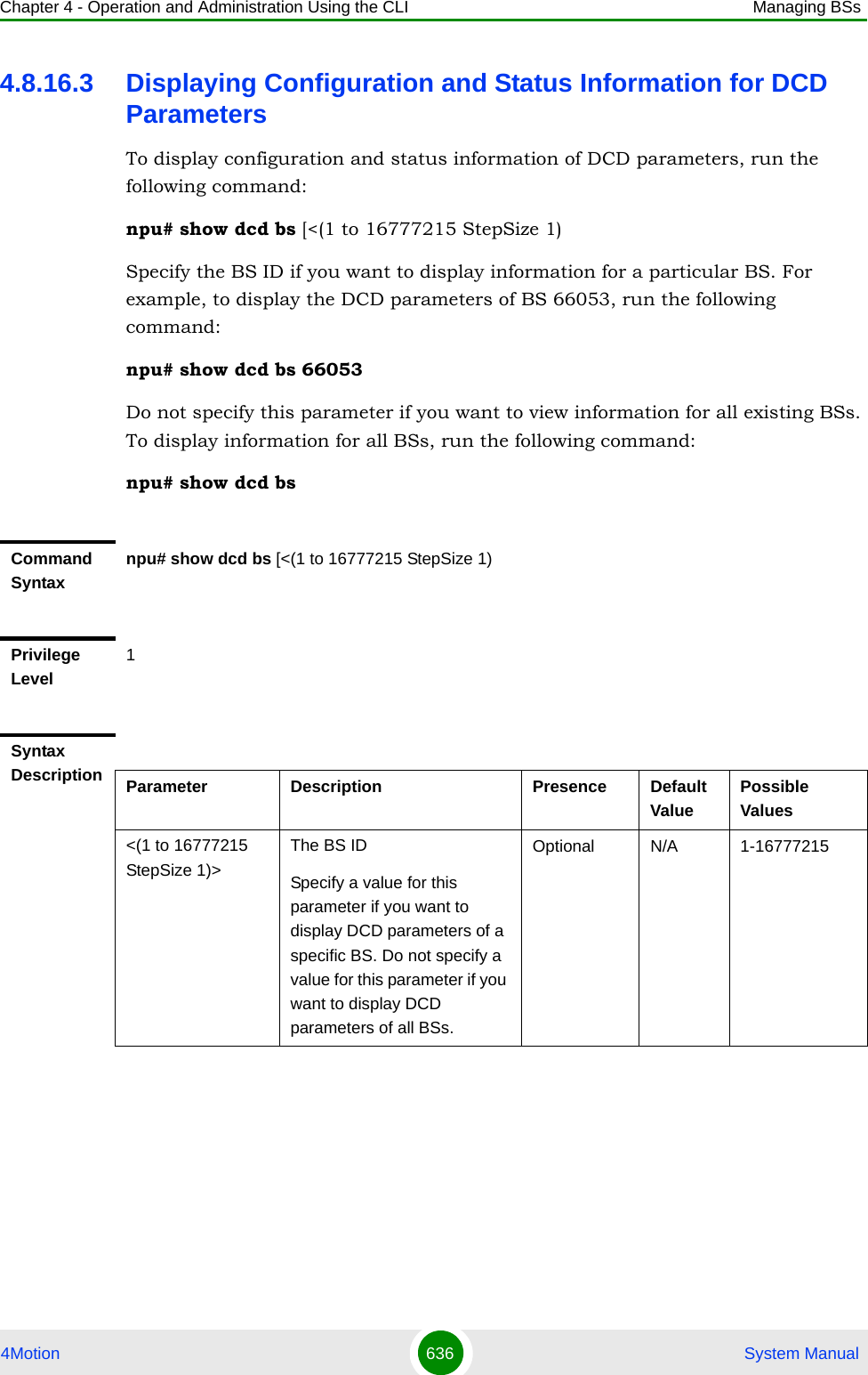
![Chapter 4 - Operation and Administration Using the CLI Managing BSs4Motion 637 System ManualIn addition to the configurable parameters, the following status parameters are also displayed:4.8.17 Managing the RF Frequency ParameterAfter enabling the BS configuration mode, you can configure the RF frequency parameter (refer to Section 4.8.17.1).You can display configuration information for the RF frequency parameter of a selected or all existing BSs (refer to Section 4.8.17.2).4.8.17.1 Configuring the RF Frequency ParameterFrom the BS configuration mode, run the following command:npu(config-bs-66053)# rf [frequency <(2302.5 to 2357.5 StepSize 0.125) | (2498.5 to 2687.5 StepSize0.125) | (3402.5 to 3597.5 StepSize 0.125) | (3602.5 to 3797.5 StepSize 0.125)>]Display Format(for each existing BS if requested for all BSs)BSIDLSB :<value>DCDConfigurationChangeCount :<value>RestartCount :<value>DCDInterval(msec) :<value>DCDTransition(frames) :<value>Command ModesGlobal command modeParameter Description Possible ValuesDCDConfigurationChangeCount Incremented by one (modulo 256) by the BS whenever any of the values of the Downlink Channel Descriptor changes.0-255RestartCount Iincremented by one (modulo 256) whenever BS restarts. The value is needed to populate neighbouring BSs neighbour tables.0-255To configure the RF frequency parameter:](https://usermanual.wiki/Alvarion-Technologies/BMAX-OR-25.Manual-3/User-Guide-1114031-Page-156.png)
![Chapter 4 - Operation and Administration Using the CLI Managing BSs4Motion 638 System ManualCommand Syntaxnpu(config-bs-66053)# rf [frequency <(2302.5 to 2357.5 StepSize 0.125) | (2498.5 to 2687.5 StepSize0.125) | (3402.5 to 3597.5 StepSize 0.125) | (3602.5 to 3797.5 StepSize 0.125)>]Privilege Level10Syntax Description Parameter Description Presence Default Value Possible Values[frequency <(2302.5 to 2357.5 StepSize 0.125) | (2498.5 to 2687.5 StepSize0.125) | (3402.5 to 3597.5 StepSize 0.125) | (3602.5 to 3797.5 StepSize 0.125)>]The center of the frequency band in which the BS will transmit, in MHz.Must be within the valid range of the relevant ODU.The indicated Possible Values are for a bandwidth of fiveMhz. For a different bandwidth, the actually valid values are from f1+1/2BW to f2-1/2BW, where f1 is the lowest frequency of the ODU’s radio band (see “Currently Available Single Port ODU Types” on page 487. Note that oDU23052360000N361by1Y0 (16) includes two bands: 2305-2320, 2345-2360 MHz.), f2 is the highest frequency of the ODU’s band, and BW is the configured bandwidth (see “Configuring the Baseband Bandwidth Parameter” on page 640). Mandatory N/A 2302.5 to 2357.5 in steps of 0.1252498.5 to 2687.5 in steps of 0.1253402.5 to 3597.5 in steps of 0.1253602.5 to 3797.5 in steps of 0.125Command Modesbs configuration modeIMPORTANTWhen creating a new BS, the mandatory frequency parameter must be configured.](https://usermanual.wiki/Alvarion-Technologies/BMAX-OR-25.Manual-3/User-Guide-1114031-Page-157.png)
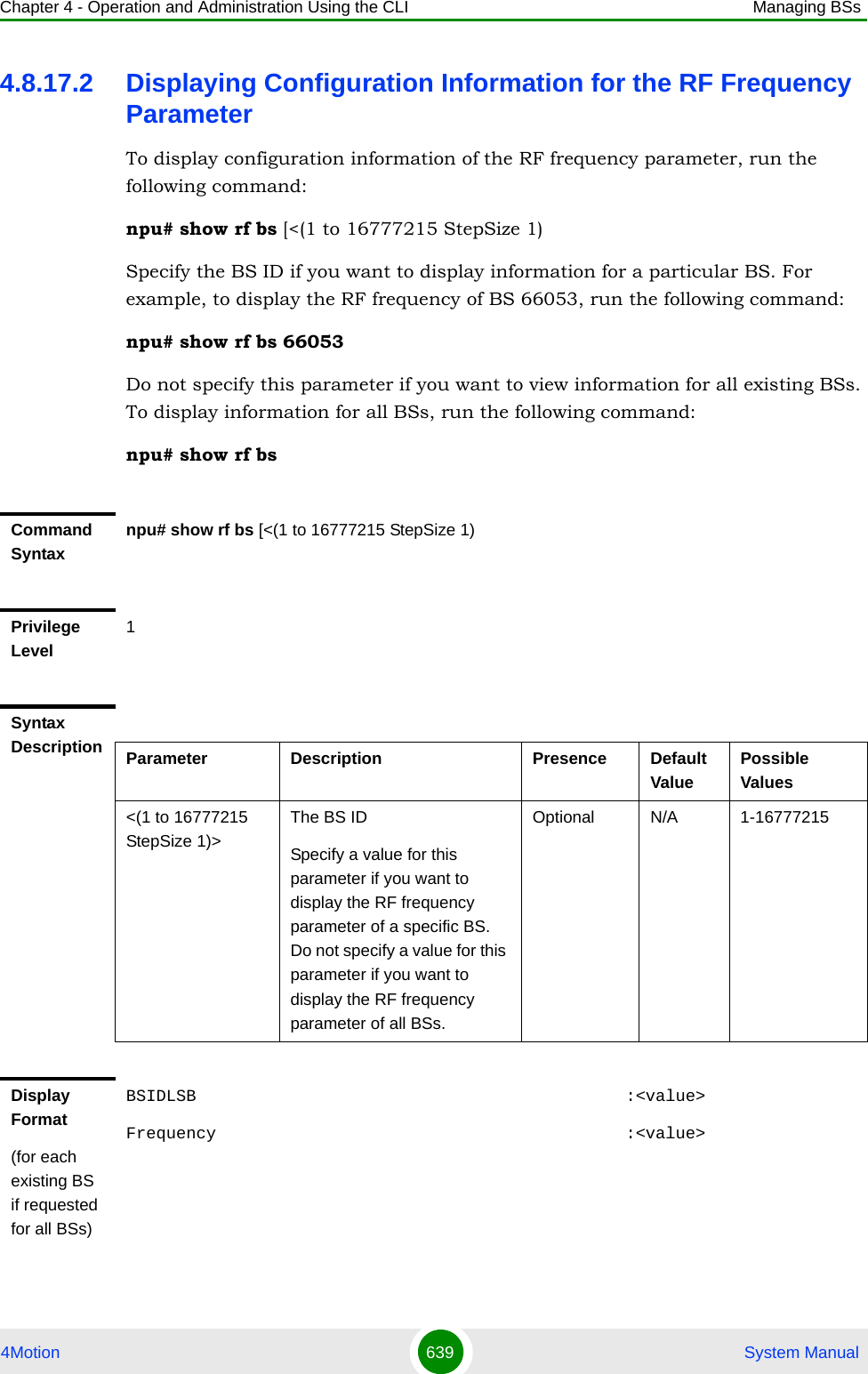
![Chapter 4 - Operation and Administration Using the CLI Managing BSs4Motion 640 System Manual4.8.18 Managing the Baseband Bandwidth ParameterAfter enabling the BS configuration mode, you can configure the Baseband bandwidth parameter (refer to Section 4.8.18.1).You can display configuration information for the Baseband bandwidth parameter of a selected or all existing BSs (refer to Section 4.8.18.2).4.8.18.1 Configuring the Baseband Bandwidth ParameterFrom the BS configuration mode, run the following command:npu(config-bs-66053)# baseband [bandwidth {fiveMHz | tenMHz | sevenMHz}]Command ModesGlobal command modeTo configure the Baseband bandwidth parameter:Command Syntaxnpu(config-bs-66053)# baseband [bandwidth {fiveMHz | tenMHz | sevenMHz} ]Privilege Level10Syntax Description Parameter Description Presence Default Value Possible Values[bandwidth {fiveMHz | tenMHz | sevenMHz} ]BS channel bandwidthMandatory N/A fiveMHztenMHzsevenMHz Command Modesbs configuration modeIMPORTANTWhen creating a new BS, the mandatory frequency parameter must be configured.](https://usermanual.wiki/Alvarion-Technologies/BMAX-OR-25.Manual-3/User-Guide-1114031-Page-159.png)
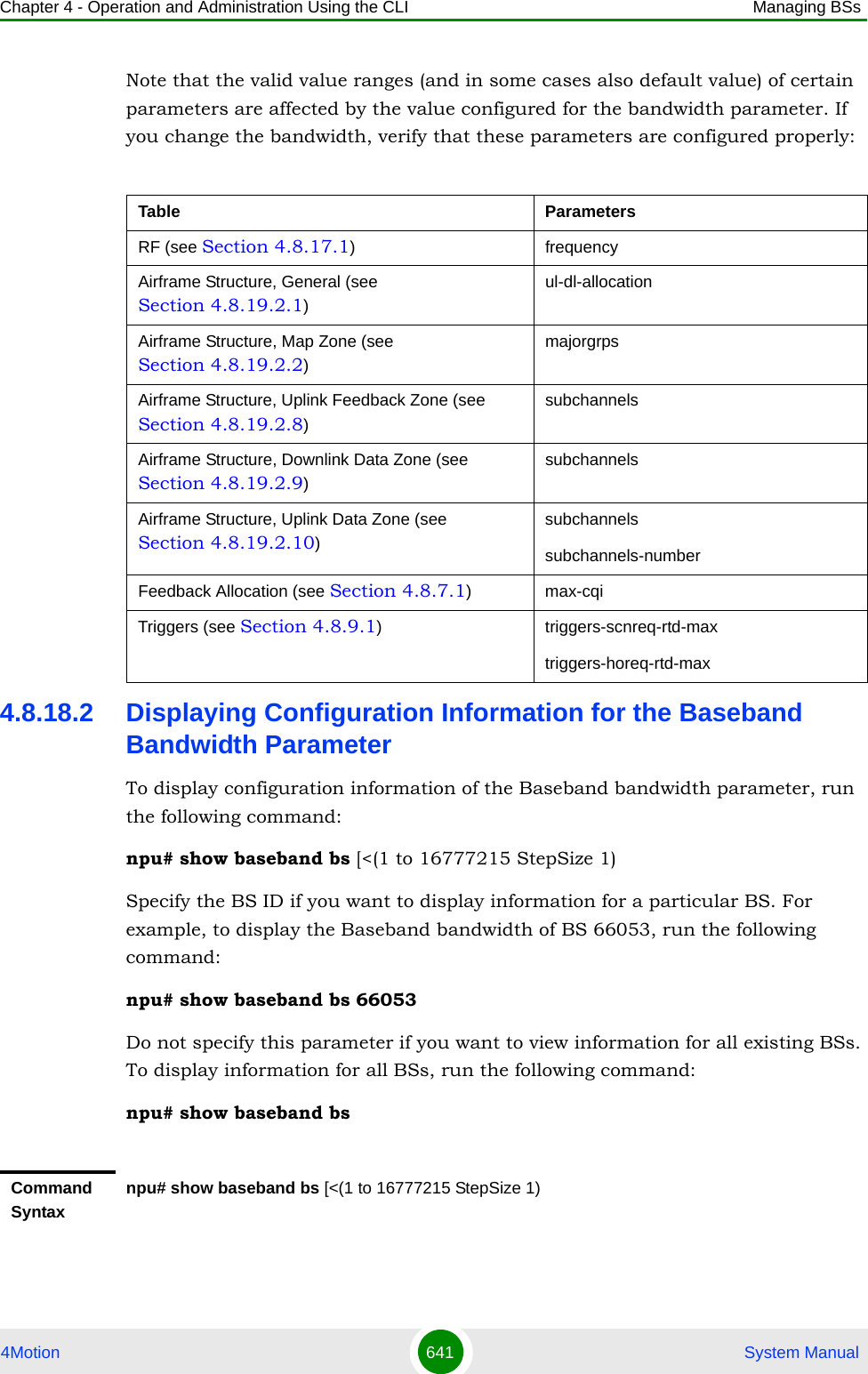
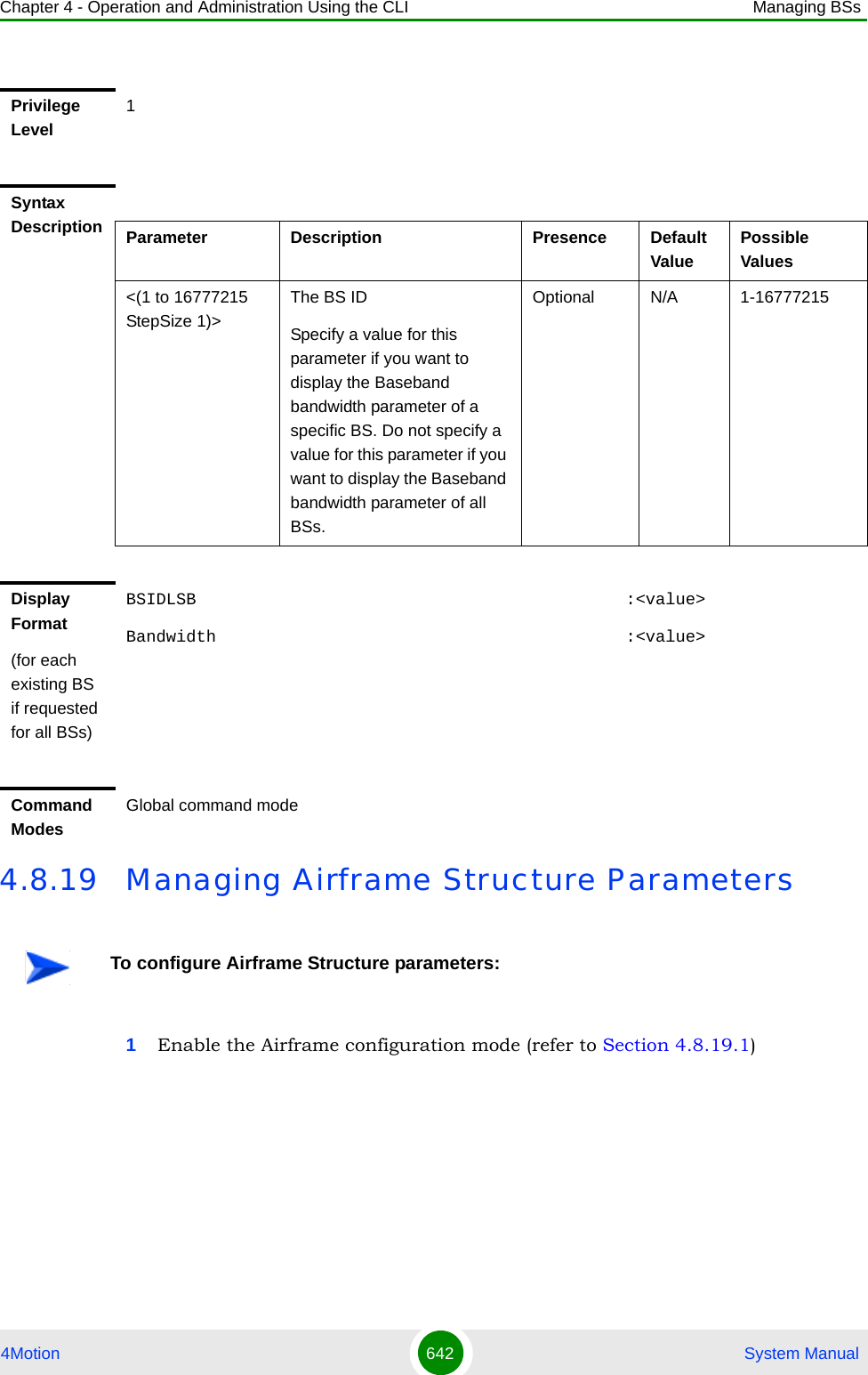
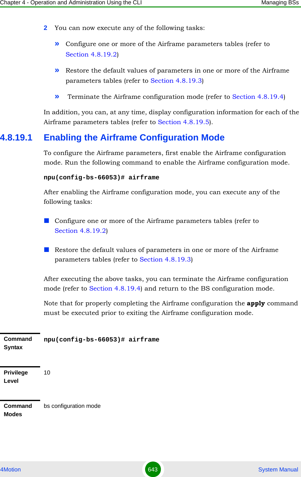
![Chapter 4 - Operation and Administration Using the CLI Managing BSs4Motion 644 System Manual4.8.19.2 Configuring Airframe ParametersAfter enabling the Airframe configuration mode you can configure the following parameters tables:General (refer to Section 4.8.19.2.1)Map Zone (refer to Section 4.8.19.2.2)Downlink Diversity (refer to Section 4.8.19.2.3)Cyclic Delay (refer to Section 4.8.19.2.4)Linear Delay (refer to Section 4.8.19.2.5)Mapping (refer to Section 4.8.19.2.6)Receive (refer to Section 4.8.19.2.7)Uplink Feedback Zone (refer to Section 4.8.19.2.8)Downlink Data Zone (refer to Section 4.8.19.2.9)Uplink Data Zone (refer to Section 4.8.19.2.10)Dynamic Permutation (refer to Section 4.8.19.2.11)4.8.19.2.1 Configuring Airframe General ParametersTo configure the Airframe General parameters, run the following command:npu(config-bs-66053-airframe)# general [cell-id <(0 to 31 StepSize 1)>] [preamble-grp <(1 to 2 StepSize 1)>] [segment <(0 to 2 StepSize 1)>] [frame-offset <(0 to 15 StepSize 1)>] [enable-ul-scrotation {TRUE | FALSE}] [ul-dl-allocation <(3 to 7 StepSize 1)>]IMPORTANTAfter completing the Airframe configuration,do not forget to execute the apply command before exiting the Airframe configuration mode:npu(config-bs-66053-airframe)# apply](https://usermanual.wiki/Alvarion-Technologies/BMAX-OR-25.Manual-3/User-Guide-1114031-Page-163.png)
![Chapter 4 - Operation and Administration Using the CLI Managing BSs4Motion 645 System ManualIMPORTANTWhen creating a new BS, all mandatory Neighbor BS General parameters must be configured.Command Syntaxnpu(config-bs-66053-airframe)# general [cell-id <(0 to 31 StepSize 1)> ] [preamble-grp <(1 to 2 StepSize 1)>] [segment <(0 to 2 StepSize 1)> ] [frame-offset <(0 to 15 StepSize 1)> ] [enable-ul-scrotation {TRUE | FALSE} ] [ul-dl-allocation <(3 to 7 StepSize 1)> ]Privilege Level10Syntax Description Parameter Description Presence Default Value Possible Values[cell-id <(0 to 31 StepSize 1)> ]The Cell ID (IDCell) used for preamble selection. Mandatory when creating a new BS.N/A 0 - 31[preamble-grp <(1 to 2 StepSize 1)>]The preamble group. A value of 2 is available only for the following combinations of segment and cell-id values:segment=0, cell-id=0, 3, 6, 9, 12, 15.segment=1, cell-id=1, 4, 7, 10, 13, 16.segment=2, cell-id=2, 5, 8, 11, 14, 17.Optional 1 1 - 2](https://usermanual.wiki/Alvarion-Technologies/BMAX-OR-25.Manual-3/User-Guide-1114031-Page-164.png)
![Chapter 4 - Operation and Administration Using the CLI Managing BSs4Motion 646 System Manual4.8.19.2.2 Configuring Airframe Map Zone ParametersTo configure the Airframe Map Zone parameters, run the following command:[segment <(0 to 2 StepSize 1)> ]The segment (BS) number in a three sector BS (0-2). This number influences the preamble selection and the major group used for the FDC transmission.Mandatory when creating a new BS.N/A 0 - 2[frame-offset <(0 to 15 StepSize 1)> ]Controls the offset applied between the internal frame count and the reported frame numberMandatory when creating a new BS.N/A 0 - 15[enable-ul-scrotation {TRUE | FALSE} ]Controls the uplink sub channel rotation functionality.If TRUE uplink sub channel rotation is enabled.Optional FALSE TRUEFALSE[ul-dl-allocation <(3 to 7 StepSize 1)> ]The total duration of the uplink in a frame, in slots. (one slot equals 3 symbols).The range is 4-7 for bandwidth = 5 or 10MHz, 3-5 for bandwidth = 7MHz. To avoid BS-BS interference, the ul-dl-allocation must be identical in all BSs in a geographical region.Mandatory when creating a new BS.N/A 3 - 7Command Modesbs airframe configuration mode](https://usermanual.wiki/Alvarion-Technologies/BMAX-OR-25.Manual-3/User-Guide-1114031-Page-165.png)
![Chapter 4 - Operation and Administration Using the CLI Managing BSs4Motion 647 System Manualnpu(config-bs-66053-airframe)# mapzone [size <(-1 to -1 StepSize 1) | (2 to 16 StepSize 2)>] [majorgrps <hex-string>] [repetition <(1 to 1 StepSize 1) | (2 to 6 StepSize 2)>]IMPORTANTWhen creating a new BS, the mandatory Airframe Map Zone majorgrps parameter must be configured.Command Syntaxnpu(config-bs-66053-airframe)# mapzone [size <(-1 to -1 StepSize 1) | (2 to 16 StepSize 2)> ] [majorgrps <hex-string>] [repetition <(1 to 1 StepSize 1) | (2 to 6 StepSize 2)> ]Privilege Level10Syntax Description Parameter Description Presence Default Value Possible Valuessize <(-1 to -1 StepSize 1) | (2 to 16 StepSize 2)>The map zone size in symbols. A value of "-1" means the map zone size will be dynamic.Optional 6 -1, 2, 4, 6, 8, 10, 12, 14, 16.](https://usermanual.wiki/Alvarion-Technologies/BMAX-OR-25.Manual-3/User-Guide-1114031-Page-166.png)
![Chapter 4 - Operation and Administration Using the CLI Managing BSs4Motion 648 System Manual4.8.19.2.3 Configuring the Airframe Downlink Diversity Mode ParameterTo configure the Airframe Downlink Diversity mode parameter, run the following command:npu(config-bs-66053-airframe)# dldiversity [mode <{none | matrixA]>]majorgrps <hex-string>The Major groups allocated to the BS for maps transmission.Two hexadecimal numbers representing 8 bits numbered 0 to 7 (left to right). Bits 0 to 5 indicate whether Subchannel Groups 0 to 5 (respectively) are allocated. Bit 6 and 7 are set to 0.If BW=5 MHz, bits 1, 3 and 5 are not relevant ("don't care").If segment (see Section 4.8.19.2.1) = 0, then bit #0 should be set.If segment = 1, then bit #2 should be set. If segment = 2, then bit #4 should be set.Mandatory when creating a new BS.N/A a string of two hexadecimal nubers.repetition <(1 to 1 StepSize 1) | (2 to 6 StepSize 2)>The basic repetition used in the transmission of the mapsOptional 6 1, 2, 4, 6Command Modesbs airframe configuration mode IMPORTANTWhen creating a new BS, the Airframe Downlink Diversity mode parameter must be configured (even if configured to the default value).Command Syntaxnpu(config-bs-66053-airframe)# dldiveraity [mode <{none | matrixA ]>]](https://usermanual.wiki/Alvarion-Technologies/BMAX-OR-25.Manual-3/User-Guide-1114031-Page-167.png)
![Chapter 4 - Operation and Administration Using the CLI Managing BSs4Motion 649 System Manual4.8.19.2.4 Configuring Airframe Cyclic Delay ParametersTo configure the Airframe Cyclic Delay parameters, run the following command:npu(config-bs-66053-airframe)# cyclicdelay [channel-1 <(0 to 4 StepSize 0.01)>] [channel-2 <(0 to 4 StepSize 0.01)>] [channel-3 <(0 to 4 StepSize 0.01)>] [channel-4 <(0 to 4 StepSize 0.01)>]Privilege Level10Syntax Description Parameter Description Presence Default Value Possible Valuesmode <{none | matrixA ]>The diversity mode used in downlink transmissions: None or MIMO Matrix A.Note that the value configured for the dldiversity mode affects the valid options for Cyclic Delay (see Section 4.8.19.2.4), Linear Delay (see Section 4.8.19.2.5) and Mapping (see Section 4.8.19.2.6) parameters.Optional none nonematrixACommand Modesbs airframe configuration mode IMPORTANTWhen creating a new BS, at least one of the Airframe Cyclic Delay parameters must be configured explicitly (even if configured to the default value). configured.Command Syntaxnpu(config-bs-66053-airframe)# cyclicdelay [channel-1 <(0 to 4 StepSize 0.01)> ] [channel-2 <(0 to 4 StepSize 0.01)> ] [channel-3 <(0 to 4 StepSize 0.01)> ] [channel-4 <(0 to 4 StepSize 0.01)> ]](https://usermanual.wiki/Alvarion-Technologies/BMAX-OR-25.Manual-3/User-Guide-1114031-Page-168.png)
![Chapter 4 - Operation and Administration Using the CLI Managing BSs4Motion 650 System Manual4.8.19.2.5 Configuring Airframe Linear Delay ParametersTo configure the Airframe Linear Delay parameters, run the following command:Privilege Level10Syntax Description Parameter Description Presence Default Value Possible Values[channel-1 <(0 to 4 StepSize 0.01)> ] Controls the cyclic delay (in microseconds) applied to PHY physical channel #1 of the Downlink Data Zone.Not relevant if dldiversity mode (see Section 4.8.19.2.3 is “none”)Optional 0 0 to 4 in steps of 0.01[channel-2 <(0 to 4 StepSize 0.01)> ]Controls the cyclic delay (in microseconds) applied to PHY physical channel #2 of the Downlink Data Zone.Not relevant if dldiversity mode (see Section 4.8.19.2.3 is “none”)Optional 0 0 to 4 in steps of 0.01[channel-3 <(0 to 4 StepSize 0.01)> ]Controls the cyclic delay (in microseconds) applied to PHY physical channel #3 of the Downlink Data Zone.Not relevant if dldiversity mode (see Section 4.8.19.2.3 is “none”)Optional 0 0 to 4 in steps of 0.01[channel-4 <(0 to 4 StepSize 0.01)> ]Controls the cyclic delay (in microseconds) applied to PHY physical channel #4 of the Downlink Data Zone.Not relevant if dldiversity mode (see Section 4.8.19.2.3 is “none”)Optional 0 0 to 4 in steps of 0.01Command Modesbs airframe configuration mode](https://usermanual.wiki/Alvarion-Technologies/BMAX-OR-25.Manual-3/User-Guide-1114031-Page-169.png)
![Chapter 4 - Operation and Administration Using the CLI Managing BSs4Motion 651 System Manualnpu(config-bs-66053-airframe)# lineardelay [channel-1 <(0 to 4 StepSize 0.01)>] [channel-2 <(0 to 4 StepSize 0.01)>] [channel-3 <(0 to 4 StepSize 0.01)>] [channel-4 <(0 to 4 StepSize 0.01)>]IMPORTANTWhen creating a new BS, at least one of the Airframe Linear Delay parameters must be configured explicitly (even if configured to the default value). configured.Command Syntaxnpu(config-bs-66053-airframe)# lineardelay [channel-1 <(0 to 4 StepSize 0.01)> ] [channel-2 <(0 to 4 StepSize 0.01)> ] [channel-3 <(0 to 4 StepSize 0.01)> ] [channel-4 <(0 to 4 StepSize 0.01)> ]Privilege Level10Syntax Description Parameter Description Presence Default Value Possible Values[channel-1 <(0 to 4 StepSize 0.01)> ] Controls the linear delay (in microseconds) applied to PHY physical channel #1 of the Downlink Data Zone.Not relevant if dldiversity mode (see Section 4.8.19.2.3 is “none”)Optional 0 0 to 4 in steps of 0.01[channel-2 <(0 to 4 StepSize 0.01)> ]Controls the linear delay (in microseconds) applied to PHY physical channel #2 of the Downlink Data Zone.Not relevant if dldiversity mode (see Section 4.8.19.2.3 is “none”)Optional 0 0 to 4 in steps of 0.01[channel-3 <(0 to 4 StepSize 0.01)> ]Controls the linear delay (in microseconds) applied to PHY physical channel #3 of the Downlink Data Zone.Not relevant if dldiversity mode (see Section 4.8.19.2.3 is “none”)Optional 0 0 to 4 in steps of 0.01](https://usermanual.wiki/Alvarion-Technologies/BMAX-OR-25.Manual-3/User-Guide-1114031-Page-170.png)
![Chapter 4 - Operation and Administration Using the CLI Managing BSs4Motion 652 System Manual4.8.19.2.6 Configuring Airframe Mapping ParametersTo configure the Airframe Mapping parameters, run the following command:npu(config-bs-66053-airframe)# mapping [channel-1 {l1 | l1slashL2 | Silence}] [channel-2 {l1 | l1slashL2 | Silence}] [channel-3 {l1 | l1slashL2 | Silence}] [channel-4 {l1 | l1slashL2 | Silence}][channel-4 <(0 to 4 StepSize 0.01)> ]Controls the linear delay (in microseconds) applied to PHY physical channel #4 of the Downlink Data Zone.Not relevant if dldiversity mode (see Section 4.8.19.2.3 is “none”)Optional 0 0 to 4 in steps of 0.01Command Modesbs airframe configuration mode IMPORTANTWhen creating a new BS, at least one of the Airframe Mapping parameters must be configured explicitly (even if configured to the default value). configured.Command Syntaxnpu(config-bs-66053-airframe)# mapping [channel-1 {l1 | l1slashL2 | Silence} ] [channel-2 {l1 | l1slashL2 | Silence} ] [channel-3 {l1 | l1slashL2 | Silence} ] [channel-4 {l1 | l1slashL2 | Silence} ]Privilege Level10Syntax Description Parameter Description Presence Default Value Possible Values](https://usermanual.wiki/Alvarion-Technologies/BMAX-OR-25.Manual-3/User-Guide-1114031-Page-171.png)
![Chapter 4 - Operation and Administration Using the CLI Managing BSs4Motion 653 System Manual[channel-1 {l1 | l1slashL2 | Silence} ]Defines which logical stream is mapped to physical channel #1:l1: Logical Stream 1.l1slashL2: Logical Streams 1 and 2.Silence: NoneIf the ODU port associated to port 1 of the AU associated to this BS is "rx only" (port-2 or port-4), the only valid value is Silence.If dldiversity mode (see Section 4.8.19.2.3 is “none”), valid options are l1 and Silence.Optional l1 l1l1slashL2Silence[channel-2 {l1 | l1slashL2 | Silence} ]Defines which logical stream is mapped to physical channel #2.l1: Logical Stream 1.l1slashL2: Logical Streams 1 and 2.Silence: NoneIf the ODU port associated to port 2 of the AU associated to this BS is "rx only" (port-2 or port-4), the only valid value is Silence.If dldiversity mode (see Section 4.8.19.2.3 is “none”), valid options are l1 and Silence.Optional l1 l1l1slashL2Silence](https://usermanual.wiki/Alvarion-Technologies/BMAX-OR-25.Manual-3/User-Guide-1114031-Page-172.png)
![Chapter 4 - Operation and Administration Using the CLI Managing BSs4Motion 654 System Manual4.8.19.2.7 Configuring Airframe Receive ParametersTo configure the Airframe Receive parameters, run the following command:npu(config-bs-66053-airframe)# rx [adminchannel-1 {TRUE | FALSE}] [adminchannel-2 {TRUE | FALSE}] [adminchannel-3 {TRUE | FALSE}] [adminchannel-4 {TRUE | FALSE}][channel-3 {l1 | l1slashL2 | Silence} ]Defines which logical stream is mapped to physical channel #3.l1: Logical Stream 1.l1slashL2: Logical Streams 1 and 2.Silence: NoneIf the ODU port associated to port 3 of the AU associated to this BS is "rx only" (port-2 or port-4), the only valid value is Silence.If dldiversity mode (see Section 4.8.19.2.3 is “none”), valid options are l1 and Silence.Optional l1 l1l1slashL2Silence[channel-4 {l1 | l1slashL2 | Silence} ]Defines which logical stream is mapped to physical channel #4.l1: Logical Stream 1.l1slashL2: Logical Streams 1 and 2.Silence: NoneIf the ODU port associated to port 4 of the AU associated to this BS is "rx only" (port-2 or port-4), the only valid value is Silence.If dldiversity mode (see Section 4.8.19.2.3 is “none”), valid options are l1 and Silence.Optional l1 l1l1slashL2SilenceCommand Modesbs airframe configuration mode](https://usermanual.wiki/Alvarion-Technologies/BMAX-OR-25.Manual-3/User-Guide-1114031-Page-173.png)
![Chapter 4 - Operation and Administration Using the CLI Managing BSs4Motion 655 System Manual4.8.19.2.8 Configuring Airframe Uplink Feedback Zone ParametersTo configure the Airframe Uplink Feedback Zone parameters, run the following command:npu(config-bs-66053-airframe)# ulfeedbackzone [subchannels <(1 to 35 StepSize 1)>] [permbase <(0 to 69 StepSize 1)>]IMPORTANTWhen creating a new BS, at least one of the Airframe Receive parameters must be configured explicitly (even if configured to the default value). configured.Command Syntaxnpu(config-bs-66053-airframe)# rx [adminchannel-1 {TRUE | FALSE} ] [adminchannel-2 {TRUE | FALSE} ] [adminchannel-3 {TRUE | FALSE} ] [adminchannel-4 {TRUE | FALSE} ]Privilege Level10Syntax Description Parameter Description Presence Default Value Possible Values[adminchannel-1 {TRUE | FALSE} ]The desired status of channel 1 in the modem receiver. A value of TRUE means enabled.Optional TRUE TRUEFALSE[adminchannel-2 {TRUE | FALSE} ]The desired status of channel 2 in the modem receiver. A value of TRUE means enabled.Optional FALSE TRUEFALSE[adminchannel-3 {TRUE | FALSE} ]The desired status of channel 3 in the modem receiver. A value of TRUE means enabled.Optional FALSE TRUEFALSE[adminchannel-4 {TRUE | FALSE} ]The desired status of channel 4 in the modem receiver. A value of TRUE means enabled.Optional FALSE TRUEFALSECommand Modesbs airframe configuration mode](https://usermanual.wiki/Alvarion-Technologies/BMAX-OR-25.Manual-3/User-Guide-1114031-Page-174.png)
![Chapter 4 - Operation and Administration Using the CLI Managing BSs4Motion 656 System Manual4.8.19.2.9 Configuring Airframe Downlink Data Zone ParametersTo configure the Airframe Downlink Data Zone parameters, run the following command:IMPORTANTWhen creating a new BS, the Airframe Structure Uplink Feedback Zone mandatory permbase parameter must be configured.Command Syntaxnpu(config-bs-66053-airframe)# ulfeedbackzone [subchannels <(11 to 35 StepSize 1)> ] [permbase <(0 to 69 StepSize 1)> ]Privilege Level10Syntax Description Parameter Description Presence Default Value Possible Values[subchannels <(1 to 35 StepSize 1)> ]The number of subchannels used in the uplink feedback zone.If bandwidth=7MHz or 10MHz, valid range is 11-35. If bandwidth=5MHz, valid range is 11-17. The default for bandwidth=5MHz should be 17.Must be higher than or equal to the value of max-cqi (see Section 4.8.7.1)Optional 35 11-35[permbase <(0 to 69 StepSize 1)> ]The permutation base used in the feedback zoneMandatory when creating a new BS.N/A 0 - 69Command Modesbs airframe configuration mode](https://usermanual.wiki/Alvarion-Technologies/BMAX-OR-25.Manual-3/User-Guide-1114031-Page-175.png)
![Chapter 4 - Operation and Administration Using the CLI Managing BSs4Motion 657 System Manualnpu(config-bs-66053-airframe)# dldatazone [subchannels <(1 to 30 StepSize 1)>] [permbase <(0 to 31 StepSize 1)>]4.8.19.2.10 Configuring Airframe Uplink Data Zone ParametersTo configure the Airframe Uplink Data Zone parameters, run the following command:npu(config-bs-66053-airframe)# uldatazone [permbase <(0 to 69 StepSize 1)>] [startallocation <(0 to 209 StepSize 1)>] [subchannels-number <(1 to 35 StepSize 1)>]IMPORTANTWhen creating a new BS, the Airframe Uplink Feedback Zone mandatory parameters must be configured.Command Syntaxnpu(config-bs-66053-airframe)# dldatazone [subchannels <(1 to 30 StepSize 1)> ] [permbase <(0 to 31 StepSize 1)> ]Privilege Level10Syntax Description Parameter Description Presence Default Value Possible Values[subchannels <(1 to 30 StepSize 1)> ]The number of subchannels used in thedownlink data zone.If bandwidth=7MHz or 10MHz, valid range is 1-30. If bandwidth=5MHz, valid range is 1-15.Mandatory when creating a new BS.N/A 1-30[permbase <(0 to 31 StepSize 1)> ]The permutation base used in the downlink data zoneMandatory when creating a new BS.N/A 0 - 31Command Modesbs airframe configuration mode](https://usermanual.wiki/Alvarion-Technologies/BMAX-OR-25.Manual-3/User-Guide-1114031-Page-176.png)
![Chapter 4 - Operation and Administration Using the CLI Managing BSs4Motion 658 System Manual4.8.19.2.11 Configuring Airframe Dynamic Permutation ParametersTo configure the Airframe Dynamic Permutation parameters, run the following command:npu(config-bs-66053-airframe)# dynamicperm [dl-permbase {TRUE | FALSE}] [ul-permbase {TRUE | FALSE}]]IMPORTANTWhen creating a new BS, the Airframe Structure Uplink Data Zone mandatory permbase parameter must be configured.Command Syntaxnpu(config-bs-66053-airframe)# uldatazone [permbase <(0 to 69 StepSize 1)> ] [startallocation <(0 to 209 StepSize 1)> ] [subchannels-number <(1 to 35 StepSize 1)> ]Privilege Level10Syntax Description Parameter Description Presence Default Value Possible Values[permbase <(0 to 69 StepSize 1)> ]The permutation base used in the uplink datazoneOptional 0 to 69 in steps of 1[startallocation <(0 to 209 StepSize 1)> ]The start allocation for the uplink datazone in slotsOptional 0 0 to 209 in steps of 1[subchannels-number <(1 to 35 StepSize 1)> ]The number of subchannels used in the uplink datazone.If bandwidth=7MHz or 10MHz, valid range is 1-35. If bandwidth=5MHz, valid range is 1-17. The default for bandwidth=5MHz should be 17.Optional 35default value=35 (7 , 10 MHz) or 17 (5MHz)1- 35Command Modesbs airframe configuration mode](https://usermanual.wiki/Alvarion-Technologies/BMAX-OR-25.Manual-3/User-Guide-1114031-Page-177.png)
![Chapter 4 - Operation and Administration Using the CLI Managing BSs4Motion 659 System Manual4.8.19.3 Restoring Default Values for Airframe Configuration ParametersAfter enabling the Airframe configuration mode you can restore the default values for non-mandatory parameters in the following parameters tables:General (refer to Section 4.8.19.3.1)Map Zone (refer to Section 4.8.19.3.2)IMPORTANTWhen creating a new BS, the Airframe Dynamic Permutation mandatory permbase parameter must be configured.Command Syntaxnpu(config-bs-66053-airframe)# dynamicperm [dl-permbase {TRUE | FALSE} ] [ul-permbase {TRUE | FALSE} ]Privilege Level10Syntax Description Parameter Description Presence Default Value Possible Valuesdl-permbase {TRUE | FALSE}The Downlink Permutation Base. If TRUE we use the same Permutation Base over all frames (Static). If FALSE the Permutation Base changes from frame to frame (Dynamic).Optional True TRUEFALSEul-permbase {TRUE | FALSE}The Uplink Permutation Base. If TRUE we use the same Permutation Base over all frames. If FALSE the Permutation Base changes from frame to frame.Optional True TRUEFALSECommand Modesbs airframe configuration mode](https://usermanual.wiki/Alvarion-Technologies/BMAX-OR-25.Manual-3/User-Guide-1114031-Page-178.png)
![Chapter 4 - Operation and Administration Using the CLI Managing BSs4Motion 660 System ManualDownlink Diversity (refer to Section 4.8.19.3.3)Cyclic Delay (refer to Section 4.8.19.3.4)Linear Delay (refer to Section 4.8.19.3.5)Mapping (refer to Section 4.8.19.3.6)Receive (refer to Section 4.8.19.3.7)Uplink Feedback Zone (refer to Section 4.8.19.3.8)Uplink Data Zone (refer to Section 4.8.19.3.9)Dynamic Permutation (refer to Section 4.8.19.3.10)4.8.19.3.1 Restoring the Default Values of Airframe General ParametersTo restore one or all of the Airframe non-mandatory General parameters to their default values, run the following command:npu(config-bs-66053-airframe)# no general [preamble-grp] [enable-ul-scrotation]You can restore only one parameter to the default value by specifying only that parameter. For example, to restore only the preamble-grp to the default value, run the following command:npu(config-bs-66053-airframe)# no general preamble-grpThe parameter will be restored to its default value, while the other parameter will remain unchanged.To restore all non-mandatory parameters to their default value, run the following command:npu(config-bs-66053-airframe)# no generalNOTERefer to Section 4.8.19.2.1 for a description and default values of these parameters.Command Syntaxnpu(config-bs-66053-airframe)# no general [preamble-grp ] [enable-ul-scrotation ]](https://usermanual.wiki/Alvarion-Technologies/BMAX-OR-25.Manual-3/User-Guide-1114031-Page-179.png)
![Chapter 4 - Operation and Administration Using the CLI Managing BSs4Motion 661 System Manual4.8.19.3.2 Restoring the Default Values of Airframe Map Zone ParametersTo restore one or all of the Airframe Map Zone non-mandatory parameters to their default values, run the following command:npu(config-bs-66053-airframe)# no mapzone [size] [repetition]You can restore only one parameter to the default value by specifying only that parameter. For example, to restore only the size parameter to the default value, run the following command:npu(config-bs-66053-airframe)# no mapzone sizeThe parameter will be restored to its default value, while the other parameter will remain unchanged.To restore all non-mandatory parameters to their default value, run the following command:npu(config-bs-66053-airframe)# no mapzonePrivilege Level10Command Modesbs airframe configuration modeNOTERefer to Section 4.8.19.2.2 for a description and default values of these parameters.Command Syntaxnpu(config-bs-66053-airframe)# no mapzone [size ] [repetition ]Privilege Level10Command Modesbs airframe configuration mode](https://usermanual.wiki/Alvarion-Technologies/BMAX-OR-25.Manual-3/User-Guide-1114031-Page-180.png)
![Chapter 4 - Operation and Administration Using the CLI Managing BSs4Motion 662 System Manual4.8.19.3.3 Restoring the Default Value of Airframe Downlink Diversity Mode ParameterTo restore the Airframe Downlink Diversity mode parameter to its default value, run the following command:npu(config-bs-66053-airframe)# no dldiversity modeSince the Downlink Diversity table contains a single parameter, it is sufficient to run the following command:npu(config-bs-66053-airframe)# no dldiversity4.8.19.3.4 Restoring the Default Values of Airframe Cyclic Delay ParametersTo restore one or all of the Airframe Cyclic Delay parameters to their default values, run the following command:npu(config-bs-66053-airframe)# no cyclicdelay [channel-1] [channel-2] [channel-3] [channel-4]You can restore only one or several parameters to the default values by specifying only those parameters. For example, to restore only the channel-1 and channel-2 parameters to the default value, run the following command:npu(config-bs-66053-airframe)# no cyclicdelay channel-1 channel-2These parameters will be restored to their default values, while the other parameters will remain unchanged.To restore all parameters to their default value, run the following command:npu(config-bs-66053-airframe)# no cyclicdelayNOTERefer to Section 4.8.19.2.3 for a description and default values of these parameters.Command Syntaxnpu(config-bs-66053-airframe)# no dldiversity [mode ]Privilege Level10Command Modesbs airframe configuration mode](https://usermanual.wiki/Alvarion-Technologies/BMAX-OR-25.Manual-3/User-Guide-1114031-Page-181.png)
![Chapter 4 - Operation and Administration Using the CLI Managing BSs4Motion 663 System Manual4.8.19.3.5 Restoring the Default Values of Airframe Linear Delay ParametersTo restore one or all of the Airframe Linear Delay parameters to their default values, run the following command:npu(config-bs-66053-airframe)# no lineardelay [channel-1] [channel-2] [channel-3] [channel-4]You can restore only one or several parameters to the default values by specifying only those parameters. For example, to restore only the channel-1 and channel-2 parameters to the default value, run the following command:npu(config-bs-66053-airframe)# no lineardelay channel-1 channel-2These parameters will be restored to their default values, while the other parameters will remain unchanged.To restore all parameters to their default value, run the following command:npu(config-bs-66053-airframe)# no lineardelayNOTERefer to Section 4.8.19.2.4 for a description and default values of these parameters.Command Syntaxnpu(config-bs-66053-airframe)# no cyclicdelay [channel-1 ] [channel-2 ] [channel-3 ] [channel-4 ]Privilege Level10Command Modesbs airframe configuration modeNOTERefer to Section 4.8.19.2.5 for a description and default values of these parameters.Command Syntaxnpu(config-bs-66053-airframe)# no lineardelay [channel-1 ] [channel-2 ] [channel-3 ] [channel-4 ]Privilege Level10](https://usermanual.wiki/Alvarion-Technologies/BMAX-OR-25.Manual-3/User-Guide-1114031-Page-182.png)
![Chapter 4 - Operation and Administration Using the CLI Managing BSs4Motion 664 System Manual4.8.19.3.6 Restoring the Default Values of Airframe Mapping ParametersTo restore one or all of the Airframe Mapping parameters to their default values, run the following command:npu(config-bs-66053-airframe)# no mapping [channel-1] [channel-2] [channel-3] [channel-4]You can restore only one or several parameters to the default values by specifying only those parameters. For example, to restore only the channel-1 and channel-2 parameters to the default value, run the following command:npu(config-bs-66053-airframe)# no mapping channel-1 channel-2These parameters will be restored to their default values, while the other parameters will remain unchanged.To restore all parameters to their default value, run the following command:npu(config-bs-66053-airframe)# no mapping4.8.19.3.7 Restoring the Default Values of Airframe Receive ParametersTo restore one or all of the Airframe Receive parameters to their default values, run the following command:npu(config-bs-66053-airframe)# no rx [adminchannel-1] [adminchannel-2] [adminchannel-3] [adminchannel-4]Command Modesbs airframe configuration modeNOTERefer to Section 4.8.19.2.6 for a description and default values of these parameters.Command Syntaxnpu(config-bs-66053-airframe)# no mapping [channel-1 ] [channel-2 ] [channel-3 ] [channel-4 ]Privilege Level10Command Modesbs airframe configuration mode](https://usermanual.wiki/Alvarion-Technologies/BMAX-OR-25.Manual-3/User-Guide-1114031-Page-183.png)
![Chapter 4 - Operation and Administration Using the CLI Managing BSs4Motion 665 System ManualYou can restore only one or several parameters to the default values by specifying only those parameters. For example, to restore only the adminchannel-1 and adminchannel-2 parameters to the default value, run the following command:npu(config-bs-66053-airframe)# no rx adminchannel-1 adminchannel-2These parameters will be restored to their default values, while the other parameters will remain unchanged.To restore all parameters to their default value, run the following command:npu(config-bs-66053-airframe)# no rx4.8.19.3.8 Restoring the Default Value of Airframe Uplink Feedback Zone Subchannels ParameterTo restore the Airframe Uplink Feedback Zone non-mandatory subchannels parameter to its default value, run the following command:npu(config-bs-66053-airframe)# no ulfeedbackzone subchannelsSince the Downlink Diversity table contains a single non-mandatory parameter, it is sufficient to run the following command:npu(config-bs-66053-airframe)# no ulfeedbackzoneNOTERefer to Section 4.8.19.2.7 for a description and default values of these parameters.Command Syntaxnpu(config-bs-66053-airframe)# no rx [adminchannel-1 ] [adminchannel-2 ] [adminchannel-3 ] [adminchannel-4 ]Privilege Level10Command Modesbs airframe configuration modeNOTERefer to Section 4.8.19.2.8 for a description and default values of these parameters.Command Syntaxnpu(config-bs-66053-airframe)# no ulfeedbackzone [subchannels ]](https://usermanual.wiki/Alvarion-Technologies/BMAX-OR-25.Manual-3/User-Guide-1114031-Page-184.png)
![Chapter 4 - Operation and Administration Using the CLI Managing BSs4Motion 666 System Manual4.8.19.3.9 Restoring the Default Values of Airframe Uplink Data Zone ParametersTo restore one or all of the Airframe Uplink Data Zone parameters to their default values, run the following command:npu(config-bs-66053-airframe)# no uldatazone [startallocation] [subchannels-number]You can restore only one or several parameters to the default values by specifying only those parameters. For example, to restore only the startallocation parameters to the default value, run the following command:npu(config-bs-66053-airframe)# no uldatazone startallocationThis parameter will be restored to the default values, while the other parameters will remain unchanged.To restore all parameters to their default value, run the following command:npu(config-bs-66053-airframe)# no uldatazone4.8.19.3.10 Restoring the Default Values of Airframe Dynamic Permutation ParametersTo restore one or all of the Airframe Dynamic Permutation parameters to their default values, run the following command:Privilege Level10Command Modesbs airframe configuration modeNOTERefer to Section 4.8.19.2.10 for a description and default values of these parameters.Command Syntaxnpu(config-bs-66053-airframe)# no uldatazone [startallocation ] [subchannels-number ]Privilege Level10Command Modesbs airframe configuration mode](https://usermanual.wiki/Alvarion-Technologies/BMAX-OR-25.Manual-3/User-Guide-1114031-Page-185.png)
![Chapter 4 - Operation and Administration Using the CLI Managing BSs4Motion 667 System Manualnpu(config-bs-66053-airframe)# no dynamicperm [dl-permbase] [ul-permbase]You can restore only one parameter to the default value by specifying only that parameter. For example, to restore only the dl-permbase to the default value, run the following command:npu(config-bs-66053-airframe)# no dynamicperm dl-permbaseThe parameter will be restored to its default value, while the other parameter will remain unchanged.To restore all non-mandatory parameters to their default value, run the following command:npu(config-bs-66053-airframe)# no dynamicperm4.8.19.4 Terminating the Airframe Configuration ModeRun the following command to terminate the Airframe configuration mode:npu(config-bs-66053-airframe)# exitNOTERefer to Section 4.8.19.2.11 for a description and default values of these parameters.Command Syntaxnpu(config-bs-66053-airframe)# no dynamicperm [dl-permbase ] [ul-permbase ]Privilege Level10Command Modesbs airframe configuration modeIMPORTANTDo not forget to execute the apply command before terminating the Airframe configuration mode: npu(config-bs-66053-airframe)# applyCommand Syntaxnpu(config-bs-66053-airframe)# exit](https://usermanual.wiki/Alvarion-Technologies/BMAX-OR-25.Manual-3/User-Guide-1114031-Page-186.png)
![Chapter 4 - Operation and Administration Using the CLI Managing BSs4Motion 668 System Manual4.8.19.5 Displaying Configuration Information for Airframe ParametersYou can display the current configuration information for the following Airframe parameters tables:General (refer to Section 4.8.19.5.1)Map Zone (refer to Section 4.8.19.5.2)Downlink Diversity (refer to Section 4.8.19.5.3)Cyclic Delay (refer to Section 4.8.19.5.4)Linear Delay (refer to Section 4.8.19.5.5)Mapping (refer to Section 4.8.19.5.6)Receive (refer to Section 4.8.19.5.7)Uplink Feedback Zone (refer to Section 4.8.19.5.8)Downlink Data Zone (refer to Section 4.8.19.5.9)Uplink Data Zone (refer to Section 4.8.19.5.10)Dynamic Permutation (refer to Section 4.8.19.5.11)All (refer to Section 4.8.19.5.12)4.8.19.5.1 Displaying Configuration Information for Airframe General ParametersTo display configuration for the Airframe General parameters, run the following command:npu# show airframe-general bs [<(1 to 16777215 StepSize 1)>]Privilege Level10Command Modesbs airframe configuration mode](https://usermanual.wiki/Alvarion-Technologies/BMAX-OR-25.Manual-3/User-Guide-1114031-Page-187.png)
![Chapter 4 - Operation and Administration Using the CLI Managing BSs4Motion 669 System ManualSpecify the BS ID if you want to display configuration for a particular BS. For example, to display the Airframe General parameters of BS 66503, run the following command:npu# show airframe-general bs 66053 Do not specify the BS ID if you want to view configuration information for all existing BSs. To display information for all BSs, run the following command:npu# show airframe-general bsCommand Syntaxnpu# show airframe-general bs [<(1 to 16777215 StepSize 1)> ]Privilege Level1Syntax Description Parameter Description Presence Default ValuePossible Values<(1 to 16777215 StepSize 1)>The BS ID Specify a value for this parameter if you want to display the Airframe General parameters of a specific BS. Do not specify a value for this parameter if you want to display the Airframe General parameters of all BSs.Optional N/A 1-16777215Display Format(for each existing Neighbour BS in each of the existing BSs if requested for all)BSIDLSB :<value>CellID :<value>PreambleGroup :<value>SegmentNumber :<value>FrameNumberOffset :<value>EnableUplinkSubchannelRotation :<value>Uplink-DownlinkAllocation(%) :<value>](https://usermanual.wiki/Alvarion-Technologies/BMAX-OR-25.Manual-3/User-Guide-1114031-Page-188.png)
![Chapter 4 - Operation and Administration Using the CLI Managing BSs4Motion 670 System Manual4.8.19.5.2 Displaying Configuration Information for Airframe Map Zone ParametersTo display configuration for the Airframe Map Zone parameters, run the following command:npu# show airframe-mapzone bs [<(1 to 16777215 StepSize 1)>]Specify the BS ID if you want to display configuration for a particular BS. For example, to display the Airframe Map Zone parameters of BS 66503, run the following command:npu# show airframe-mapzone bs 66053 Do not specify the BS ID if you want to view configuration information for all existing BSs. To display information for all BSs, run the following command:npu# show airframe-mapzone bsCommand ModesGlobal command modeCommand Syntaxnpu# show airframe-mapzone bs [<(1 to 16777215 StepSize 1)> ]Privilege Level1Syntax Description Parameter Description Presence Default ValuePossible Values<(1 to 16777215 StepSize 1)>The BS ID Specify a value for this parameter if you want to display the Airframe Map Zone parameters of a specific BS. Do not specify a value for this parameter if you want to display the Airframe Map Zone parameters of all BSs.Optional N/A 1-16777215](https://usermanual.wiki/Alvarion-Technologies/BMAX-OR-25.Manual-3/User-Guide-1114031-Page-189.png)
![Chapter 4 - Operation and Administration Using the CLI Managing BSs4Motion 671 System Manual4.8.19.5.3 Displaying Configuration Information for Airframe Downlink Diversity ParametersTo display configuration for the Airframe Downlink Diversity parameters, run the following command:npu# show airframe-dldiversity bs [<(1 to 16777215 StepSize 1)>]Specify the BS ID if you want to display configuration for a particular BS. For example, to display the Airframe Downlink Diversity parameters of BS 66503, run the following command:npu# show airframe-dldiversity bs 66053 Do not specify the BS ID if you want to view configuration information for all existing BSs. To display information for all BSs, run the following command:npu# show airframe-dldiversity bsDisplay Format(for each existing Neighbour BS in each of the existing BSs if requested for all)BSIDLSB :<value>MapZoneSize(symbols) :<value>MapMajorGroups :<value>BasicMapRepetitions :<value>Command ModesGlobal command modeCommand Syntaxnpu# show airframe-mapzone bs [<(1 to 16777215 StepSize 1)> ]Privilege Level1](https://usermanual.wiki/Alvarion-Technologies/BMAX-OR-25.Manual-3/User-Guide-1114031-Page-190.png)
![Chapter 4 - Operation and Administration Using the CLI Managing BSs4Motion 672 System Manual4.8.19.5.4 Displaying Configuration Information for Airframe Cyclic Delay ParametersTo display configuration for the Airframe Cyclic Delay parameters, run the following command:npu# show airframe-cyclicdelay bs [<(1 to 16777215 StepSize 1)>]Specify the BS ID if you want to display configuration for a particular BS. For example, to display the Airframe Cyclic Delay parameters of BS 66503, run the following command:npu# show airframe-cyclicdelay bs 66053 Do not specify the BS ID if you want to view configuration information for all existing BSs. To display information for all BSs, run the following command:Syntax Description Parameter Description Presence Default ValuePossible Values<(1 to 16777215 StepSize 1)>The BS ID Specify a value for this parameter if you want to display the Airframe Downlink Diversity parameters of a specific BS. Do not specify a value for this parameter if you want to display the Airframe Downlink Diversity parameters of all BSs.Optional N/A 1-16777215Display Format(for each existing Neighbour BS in each of the existing BSs if requested for all)BSIDLSB :<value>DownlinkDataDiversityMode :<value>Command ModesGlobal command mode](https://usermanual.wiki/Alvarion-Technologies/BMAX-OR-25.Manual-3/User-Guide-1114031-Page-191.png)
![Chapter 4 - Operation and Administration Using the CLI Managing BSs4Motion 673 System Manualnpu# show airframe-cyclicdelay bs4.8.19.5.5 Displaying Configuration Information for Airframe Linear Delay ParametersTo display configuration for the Airframe Linear Delay parameters, run the following command:Command Syntaxnpu# show airframe-cyclicdelay bs [<(1 to 16777215 StepSize 1)> ]Privilege Level1Syntax Description Parameter Description Presence Default ValuePossible Values<(1 to 16777215 StepSize 1)>The BS ID Specify a value for this parameter if you want to display the Airframe Cyclic Delay parameters of a specific BS. Do not specify a value for this parameter if you want to display the Airframe Cyclic Delay parameters of all BSs.Optional N/A 1-16777215Display Format(for each existing Neighbour BS in each of the existing BSs if requested for all)BSIDLSB :<value>CyclicDelayChannel1(microseconds) :<value>CyclicDelayChannel2(microseconds) :<value>CyclicDelayChannel3(microseconds) :<value>CyclicDelayChannel4(microseconds) :<value>Command ModesGlobal command mode](https://usermanual.wiki/Alvarion-Technologies/BMAX-OR-25.Manual-3/User-Guide-1114031-Page-192.png)
![Chapter 4 - Operation and Administration Using the CLI Managing BSs4Motion 674 System Manualnpu# show airframe-lineardelay bs [<(1 to 16777215 StepSize 1)>]Specify the BS ID if you want to display configuration for a particular BS. For example, to display the Airframe Linear Delay parameters of BS 66503, run the following command:npu# show airframe-lineardelay bs 66053 Do not specify the BS ID if you want to view configuration information for all existing BSs. To display information for all BSs, run the following command:npu# show airframe-lineardelay bsCommand Syntaxnpu# show airframe-lineardelay bs [<(1 to 16777215 StepSize 1)> ]Privilege Level1Syntax Description Parameter Description Presence Default ValuePossible Values<(1 to 16777215 StepSize 1)>The BS ID Specify a value for this parameter if you want to display the Airframe Linear Delay parameters of a specific BS. Do not specify a value for this parameter if you want to display the Airframe Linear Delay parameters of all BSs.Optional N/A 1-16777215Display Format(for each existing Neighbour BS in each of the existing BSs if requested for all)BSIDLSB :<value>LinearDelayChannel1(microseconds) :<value>LinearDelayChannel2(microseconds) :<value>LinearDelayChannel3(microseconds) :<value>LinearDelayChannel4(microseconds) :<value>](https://usermanual.wiki/Alvarion-Technologies/BMAX-OR-25.Manual-3/User-Guide-1114031-Page-193.png)
![Chapter 4 - Operation and Administration Using the CLI Managing BSs4Motion 675 System Manual4.8.19.5.6 Displaying Configuration Information for Airframe Mapping ParametersTo display configuration for the Airframe Mapping parameters, run the following command:npu# show airframe-mapping bs [<(1 to 16777215 StepSize 1)>]Specify the BS ID if you want to display configuration for a particular BS. For example, to display the Airframe Mapping parameters of BS 66503, run the following command:npu# show airframe-mapping bs 66053 Do not specify the BS ID if you want to view configuration information for all existing BSs. To display information for all BSs, run the following command:npu# show airframe-mapping bsCommand ModesGlobal command modeCommand Syntaxnpu# show airframe-mapping bs [<(1 to 16777215 StepSize 1)> ]Privilege Level1Syntax Description Parameter Description Presence Default ValuePossible Values<(1 to 16777215 StepSize 1)>The BS ID Specify a value for this parameter if you want to display the Airframe Mapping parameters of a specific BS. Do not specify a value for this parameter if you want to display the Airframe Mapping parameters of all BSs.Optional N/A 1-16777215](https://usermanual.wiki/Alvarion-Technologies/BMAX-OR-25.Manual-3/User-Guide-1114031-Page-194.png)
![Chapter 4 - Operation and Administration Using the CLI Managing BSs4Motion 676 System Manual4.8.19.5.7 Displaying Configuration Information for Airframe Receive ParametersTo display configuration for the Airframe Receive parameters, run the following command:npu# show airframe-rx bs [<(1 to 16777215 StepSize 1)>]Specify the BS ID if you want to display configuration for a particular BS. For example, to display the Airframe Receive parameters of BS 66503, run the following command:npu# show airframe-rx bs 66053 Do not specify the BS ID if you want to view configuration information for all existing BSs. To display information for all BSs, run the following command:npu# show airframe-rx bsDisplay Format(for each existing Neighbour BS in each of the existing BSs if requested for all)BSIDLSB :<value>LogicalStramMappingChannel1 :<value>LogicalStramMappingChannel2 :<value>LogicalStramMappingChannel3 :<value>LogicalStramMappingChannel4 :<value>Command ModesGlobal command modeCommand Syntaxnpu# show airframe-rx bs [<(1 to 16777215 StepSize 1)> ]Privilege Level1](https://usermanual.wiki/Alvarion-Technologies/BMAX-OR-25.Manual-3/User-Guide-1114031-Page-195.png)
![Chapter 4 - Operation and Administration Using the CLI Managing BSs4Motion 677 System Manual4.8.19.5.8 Displaying Configuration Information for Airframe Uplink Feedback Zone ParametersTo display configuration for the Airframe Uplink Feedback Zone parameters, run the following command:npu# show airframe-ulfeedbackzone bs [<(1 to 16777215 StepSize 1)>]Specify the BS ID if you want to display configuration for a particular BS. For example, to display the Airframe Uplink Feedback Zone parameters of BS 66503, run the following command:npu# show airframe-ulfeedbackzone bs 66053 Do not specify the BS ID if you want to view configuration information for all existing BSs. To display information for all BSs, run the following command:npu# show airframe-ulfeedbackzone bsSyntax Description Parameter Description Presence Default ValuePossible Values<(1 to 16777215 StepSize 1)>The BS ID Specify a value for this parameter if you want to display the Airframe Receive parameters of a specific BS. Do not specify a value for this parameter if you want to display the Airframe Receive parameters of all BSs.Optional N/A 1-16777215Display Format(for each existing Neighbour BS in each of the existing BSs if requested for all)BSIDLSB :<value>AdminStatusChannel1 :<value>AdminStatusChannel2 :<value>AdminStatusChannel3 :<value>AdminStatusChannel4 :<value>Command ModesGlobal command mode](https://usermanual.wiki/Alvarion-Technologies/BMAX-OR-25.Manual-3/User-Guide-1114031-Page-196.png)
![Chapter 4 - Operation and Administration Using the CLI Managing BSs4Motion 678 System Manual4.8.19.5.9 Displaying Configuration Information for Airframe Downlink Data Zone ParametersTo display configuration for the Airframe Downlink Data Zone parameters, run the following command:npu# show airframe-dldatazone bs [<(1 to 16777215 StepSize 1)>]Command Syntaxnpu# show airframe-ulfeedbackzone bs [<(1 to 16777215 StepSize 1)> ]Privilege Level1Syntax Description Parameter Description Presence Default ValuePossible Values<(1 to 16777215 StepSize 1)>The BS ID Specify a value for this parameter if you want to display the Airframe Uplink Feedback Zone parameters of a specific BS. Do not specify a value for this parameter if you want to display the Airframe Uplink Feedback Zone parameters of all BSs.Optional N/A 1-16777215Display Format(for each existing Neighbour BS in each of the existing BSs if requested for all)BSIDLSB :<value>ULFeedbackZoneNumberofSub-Channels :<value>ULFeedbackZonePermutationBase :<value>Command ModesGlobal command mode](https://usermanual.wiki/Alvarion-Technologies/BMAX-OR-25.Manual-3/User-Guide-1114031-Page-197.png)
![Chapter 4 - Operation and Administration Using the CLI Managing BSs4Motion 679 System ManualSpecify the BS ID if you want to display configuration for a particular BS. For example, to display the Airframe Downlink Data Zone parameters of BS 66503, run the following command:npu# show airframe-dldatazone bs 66053 Do not specify the BS ID if you want to view configuration information for all existing BSs. To display information for all BSs, run the following command:npu# show airframe-dldatazone bsCommand Syntaxnpu# show airframe-dldatazone bs [<(1 to 16777215 StepSize 1)> ]Privilege Level1Syntax Description Parameter Description Presence Default ValuePossible Values<(1 to 16777215 StepSize 1)>The BS ID Specify a value for this parameter if you want to display the Airframe Downlink Data Zone parameters of a specific BS. Do not specify a value for this parameter if you want to display the Airframe Downlink Data Zone parameters of all BSs.Optional N/A 1-16777215Display Format(for each existing Neighbour BS in each of the existing BSs if requested for all)BSIDLSB :<value>DLDATAZoneNumberofSub-Channels :<value>DLDATAZonePermutationBase :<value>](https://usermanual.wiki/Alvarion-Technologies/BMAX-OR-25.Manual-3/User-Guide-1114031-Page-198.png)
![Chapter 4 - Operation and Administration Using the CLI Managing BSs4Motion 680 System Manual4.8.19.5.10 Displaying Configuration Information for Airframe Uplink Data Zone ParametersTo display configuration for the Airframe Uplink Data Zone parameters, run the following command:npu# show airframe-uldatazone bs [<(1 to 16777215 StepSize 1)>]Specify the BS ID if you want to display configuration for a particular BS. For example, to display the Airframe Uplink Data Zone parameters of BS 66503, run the following command:npu# show airframe-uldatazone bs 66053 Do not specify the BS ID if you want to view configuration information for all existing BSs. To display information for all BSs, run the following command:npu# show airframe-uldatazone bsCommand ModesGlobal command modeCommand Syntaxnpu# show airframe-uldatazone bs [<(1 to 16777215 StepSize 1)> ]Privilege Level1Syntax Description Parameter Description Presence Default ValuePossible Values<(1 to 16777215 StepSize 1)>The BS ID Specify a value for this parameter if you want to display the Airframe Uplink Data Zone parameters of a specific BS. Do not specify a value for this parameter if you want to display the Airframe Uplink Data Zone parameters of all BSs.Optional N/A 1-16777215](https://usermanual.wiki/Alvarion-Technologies/BMAX-OR-25.Manual-3/User-Guide-1114031-Page-199.png)
![Chapter 4 - Operation and Administration Using the CLI Managing BSs4Motion 681 System Manual4.8.19.5.11 Displaying Configuration Information for Airframe Dynamic Permutation ParametersTo display configuration for the Airframe Dynamic Permutation parameters, run the following command:npu# show airframe-dynamicperm bs [<(1 to 16777215 StepSize 1)>]Specify the BS ID if you want to display configuration for a particular BS. For example, to display the Airframe Dynamic Permutation parameters of BS 66503, run the following command:npu# show airframe-dynamicperm bs 66053 Do not specify the BS ID if you want to view configuration information for all existing BSs. To display information for all BSs, run the following command:npu# show airframe-dynamicperm bsDisplay Format(for each existing Neighbour BS in each of the existing BSs if requested for all)BSIDLSB :<value>ULDATAPermutationBase :<value>StartAllocation(Slots) :<value>ULDATAZoneNumberofSub-Channels :<value>Command ModesGlobal command modeCommand Syntaxnpu# show airframe-dynamicperm bs [<(1 to 16777215 StepSize 1)> ]Privilege Level1](https://usermanual.wiki/Alvarion-Technologies/BMAX-OR-25.Manual-3/User-Guide-1114031-Page-200.png)