Alvarion Technologies DS11 Wireless LAN device User Manual 43501
Alvarion Ltd. Wireless LAN device 43501
Contents
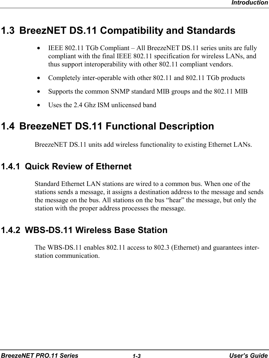
- 1. Users manual for indoor model of EUT
- 2. Users manual for outdoor model of EUT
- 3. outdoor users guide
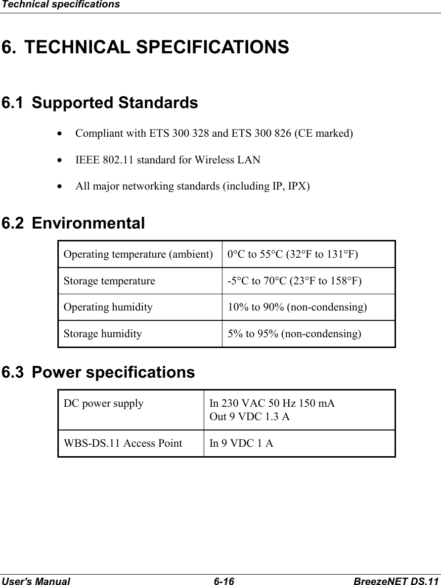
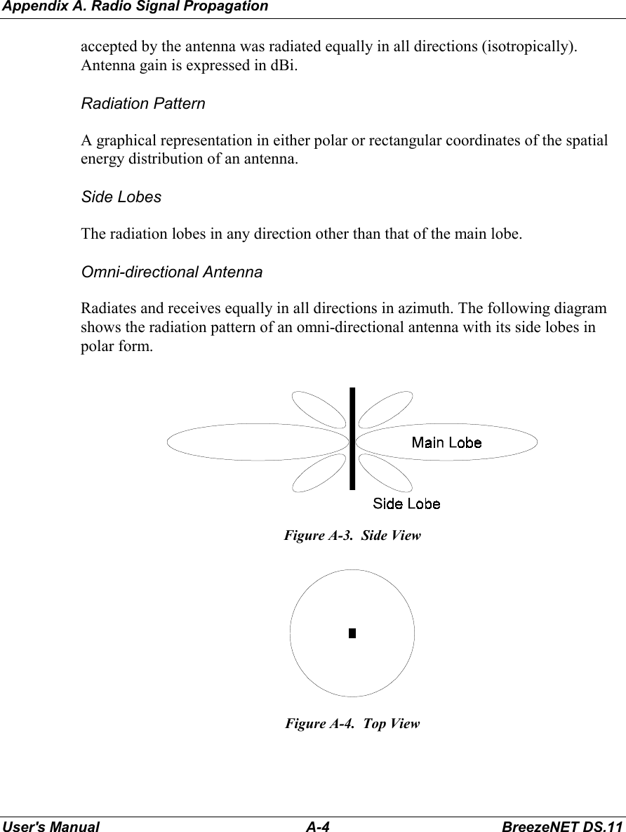
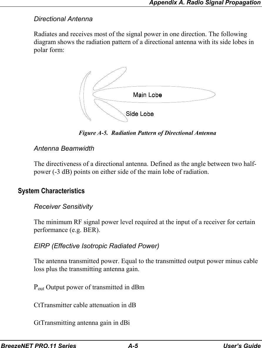
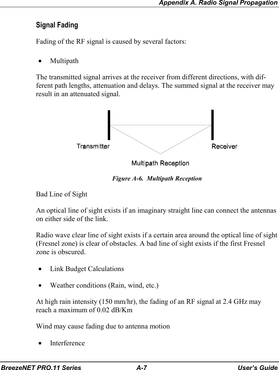
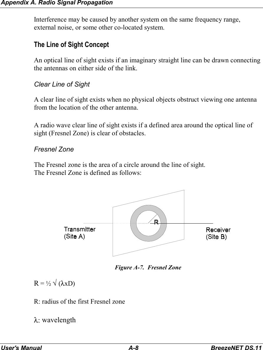
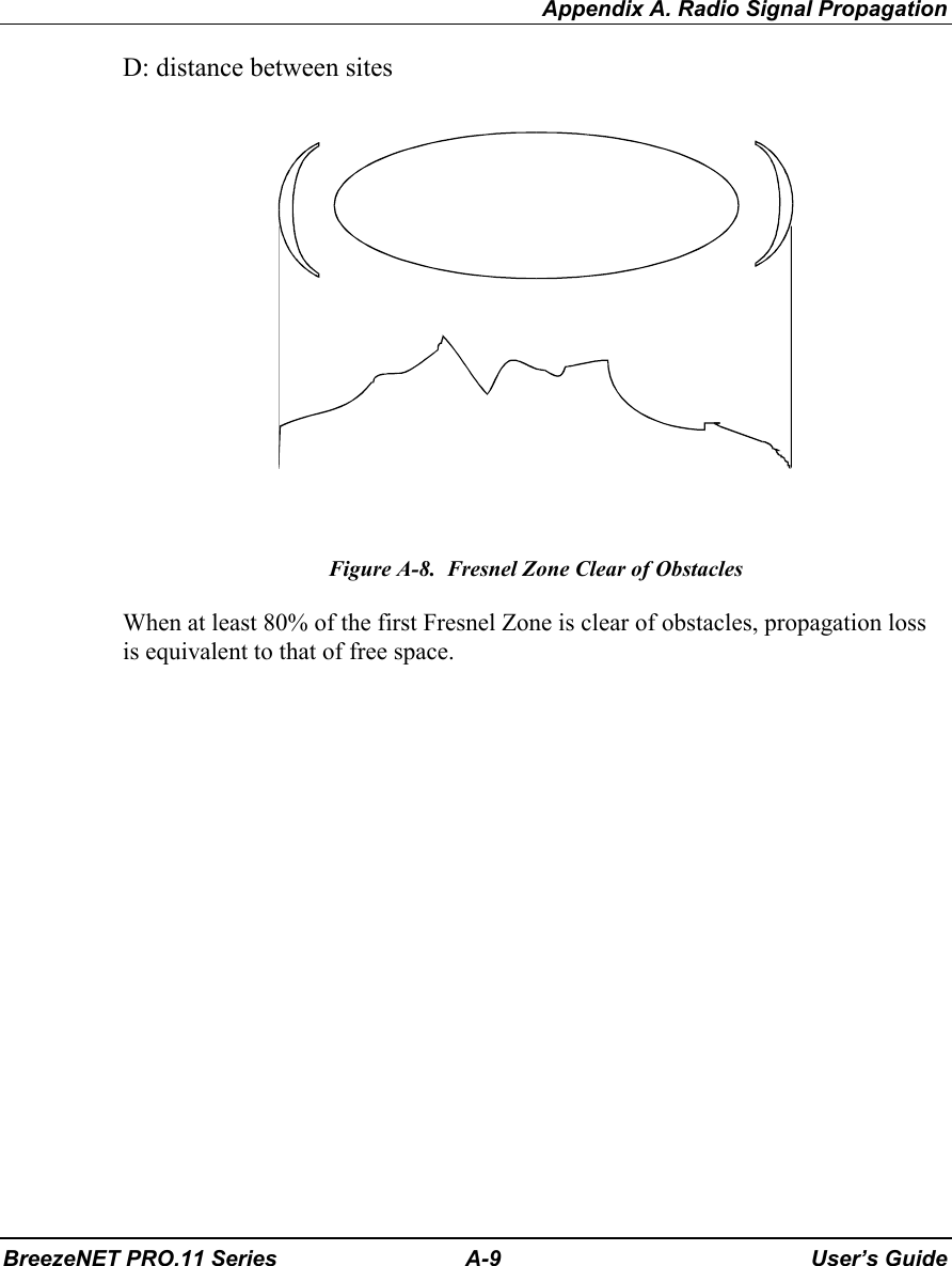
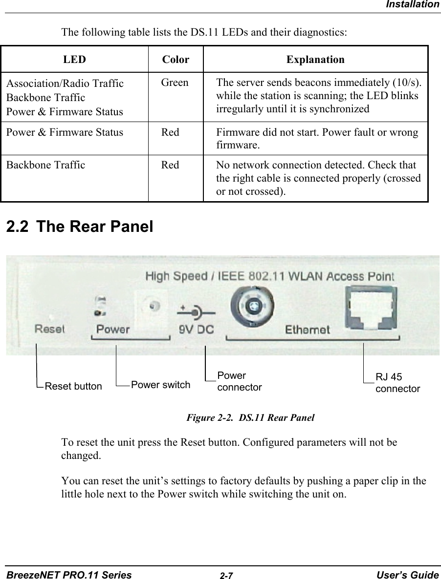
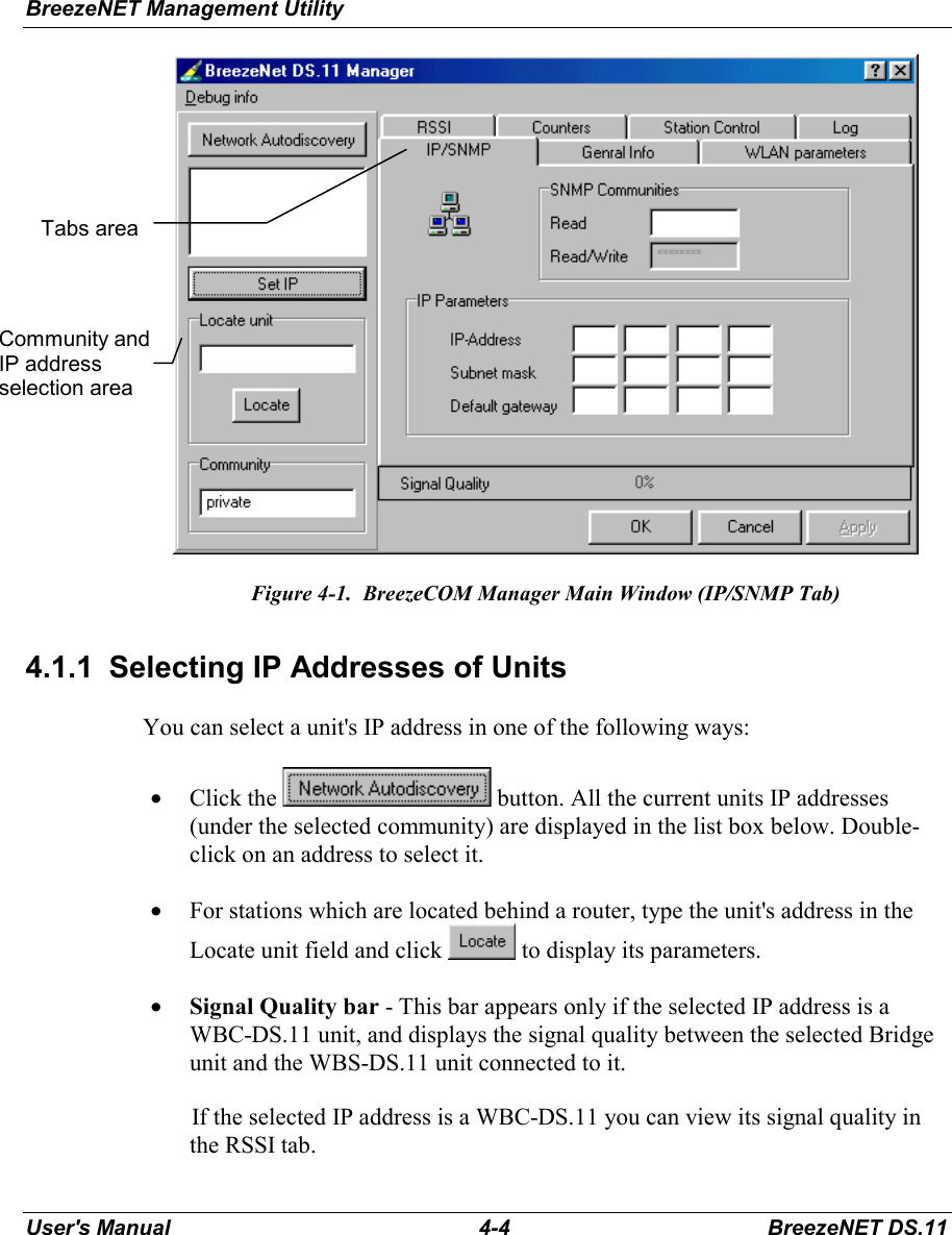
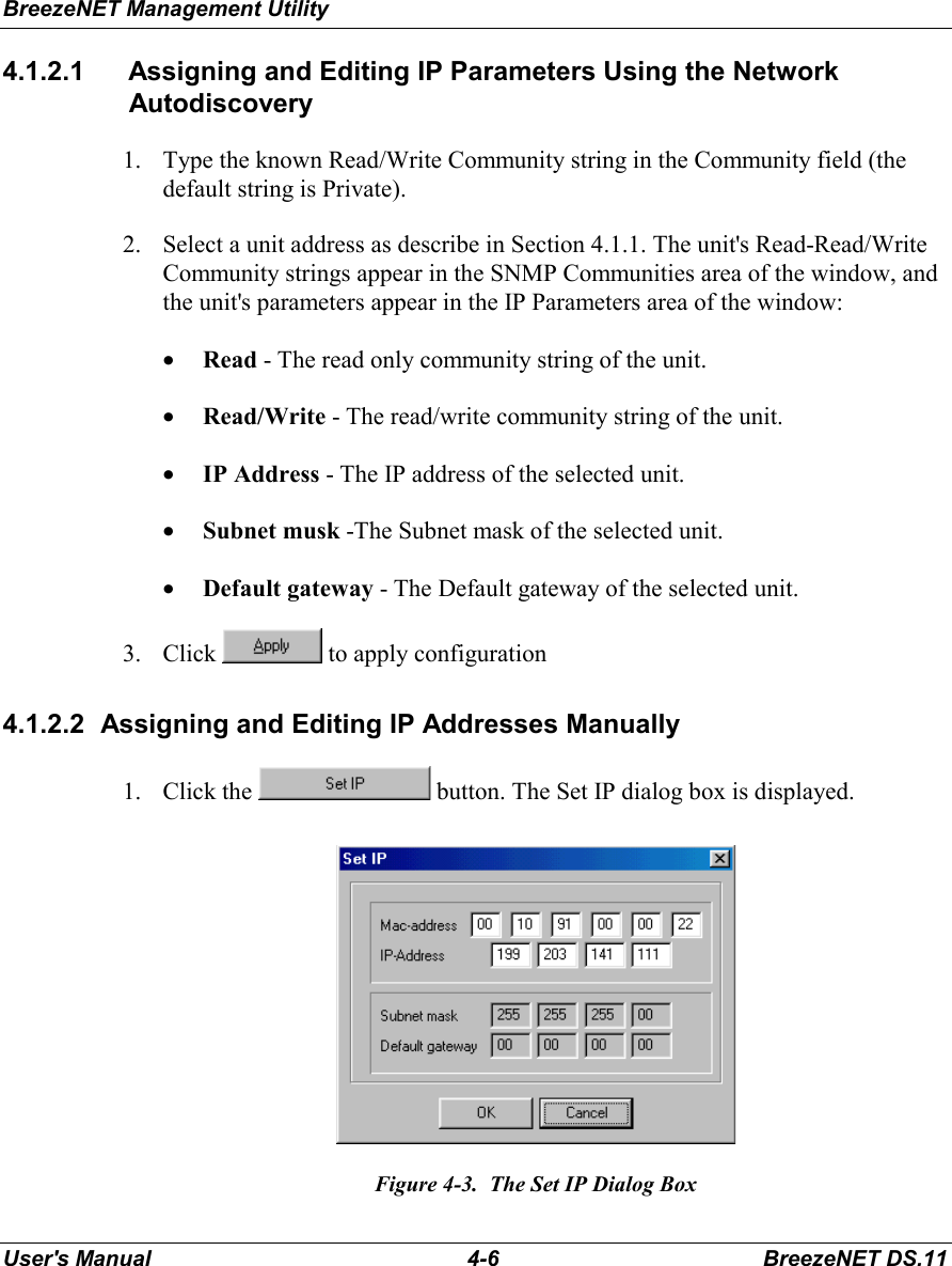
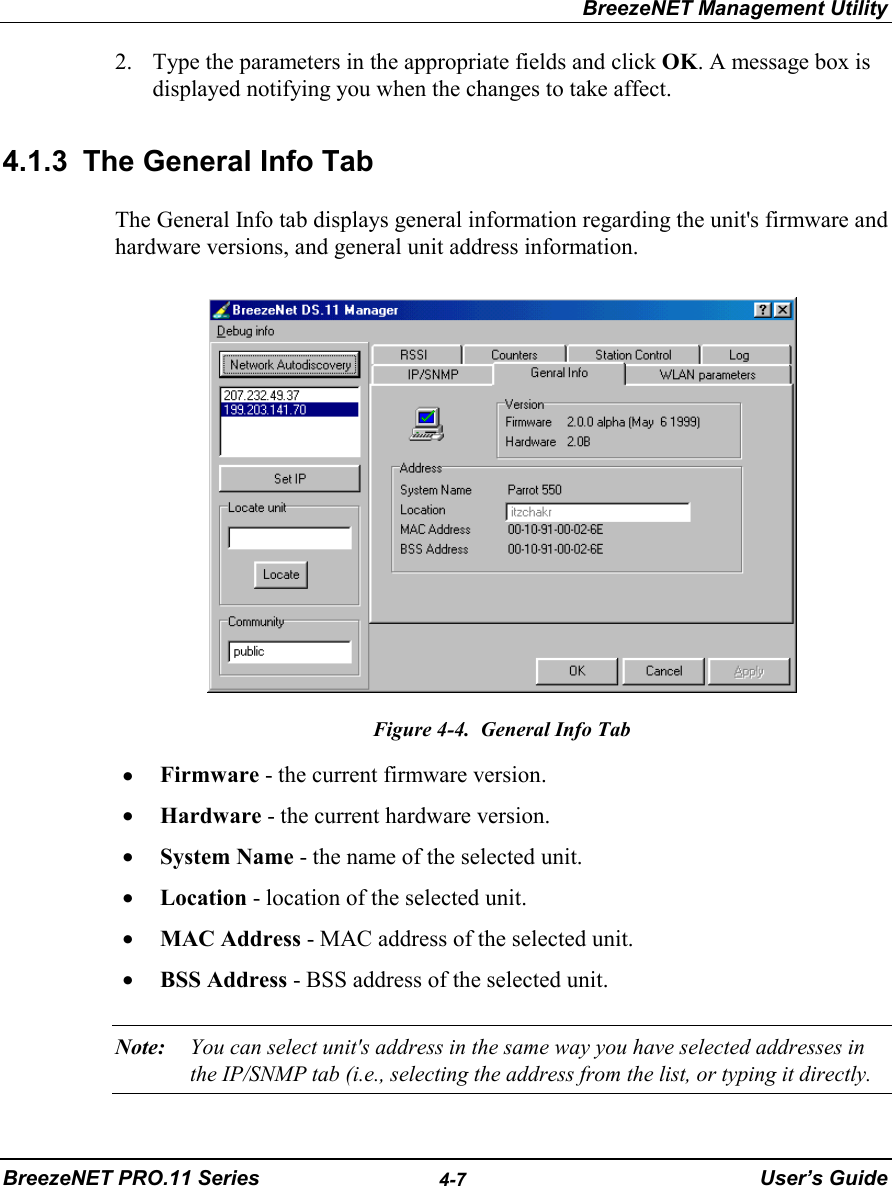
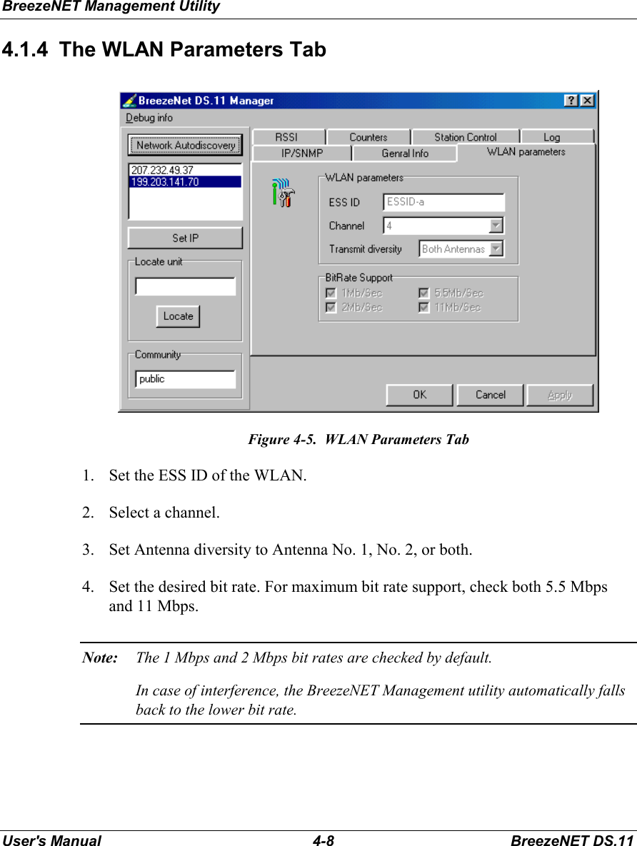
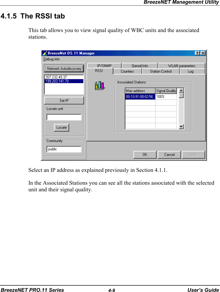
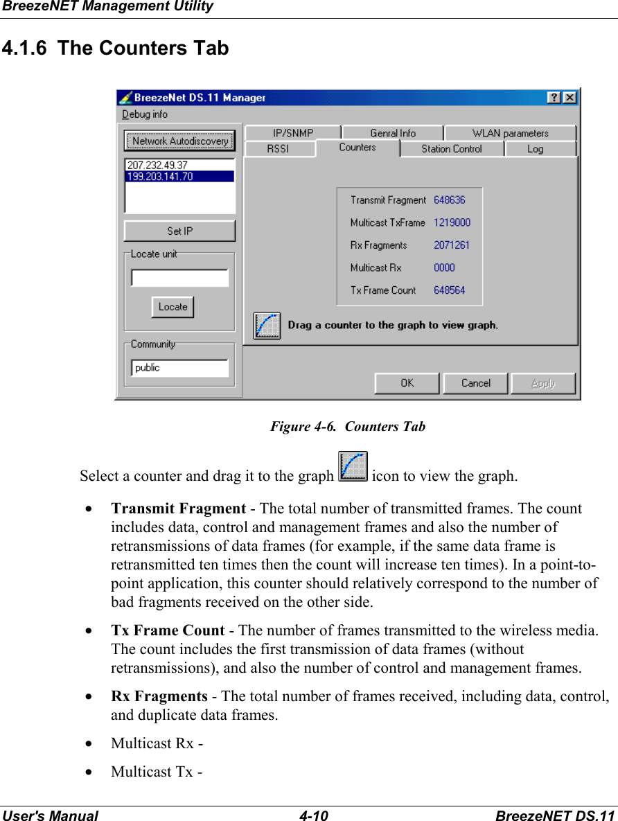
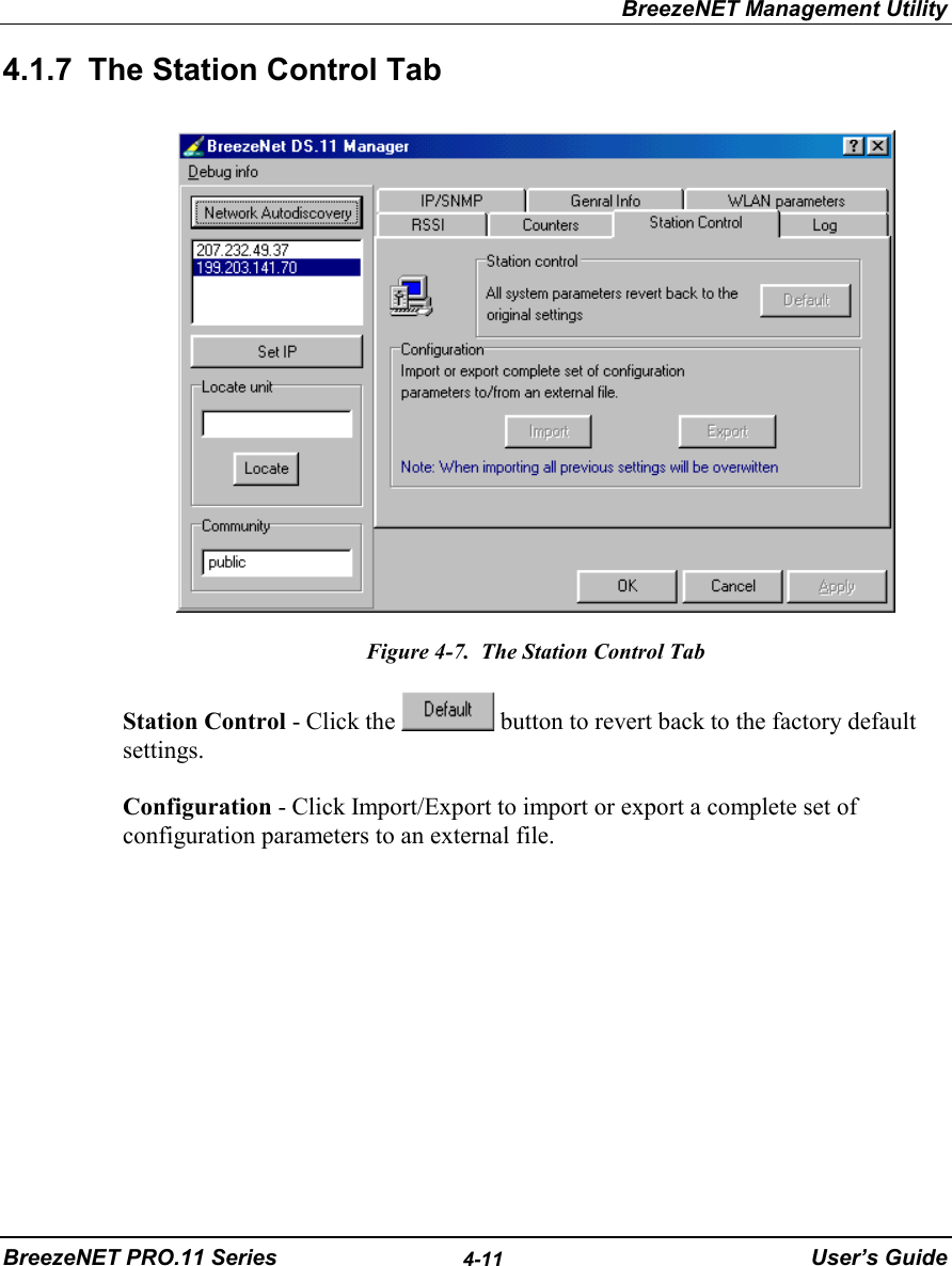
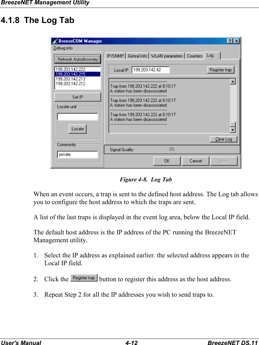
Users manual for outdoor model of EUT
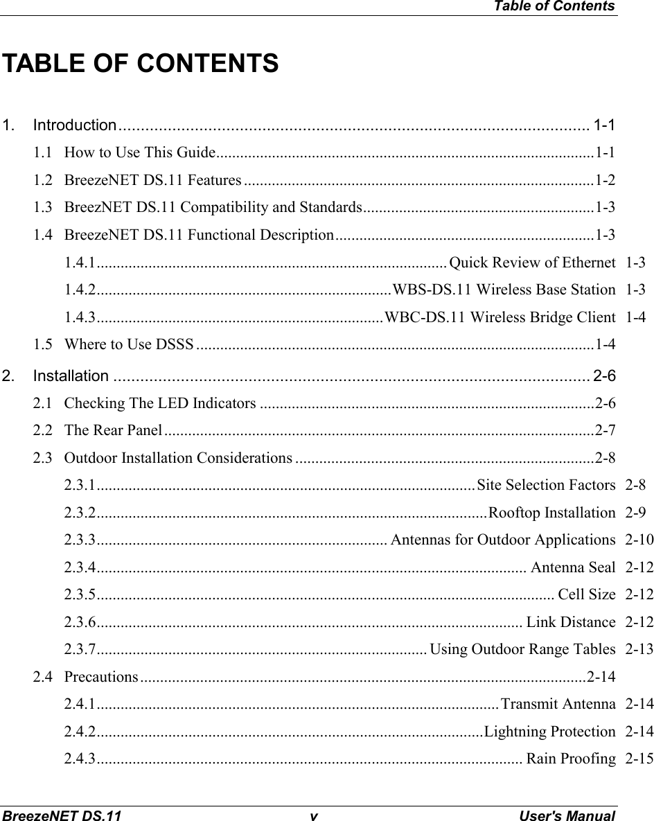
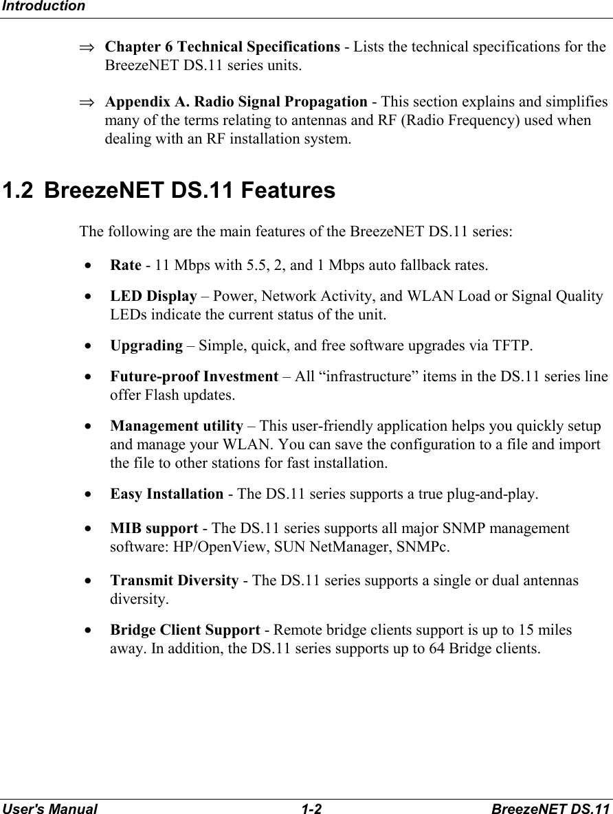
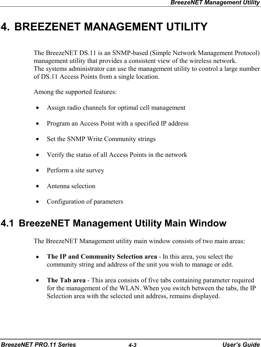

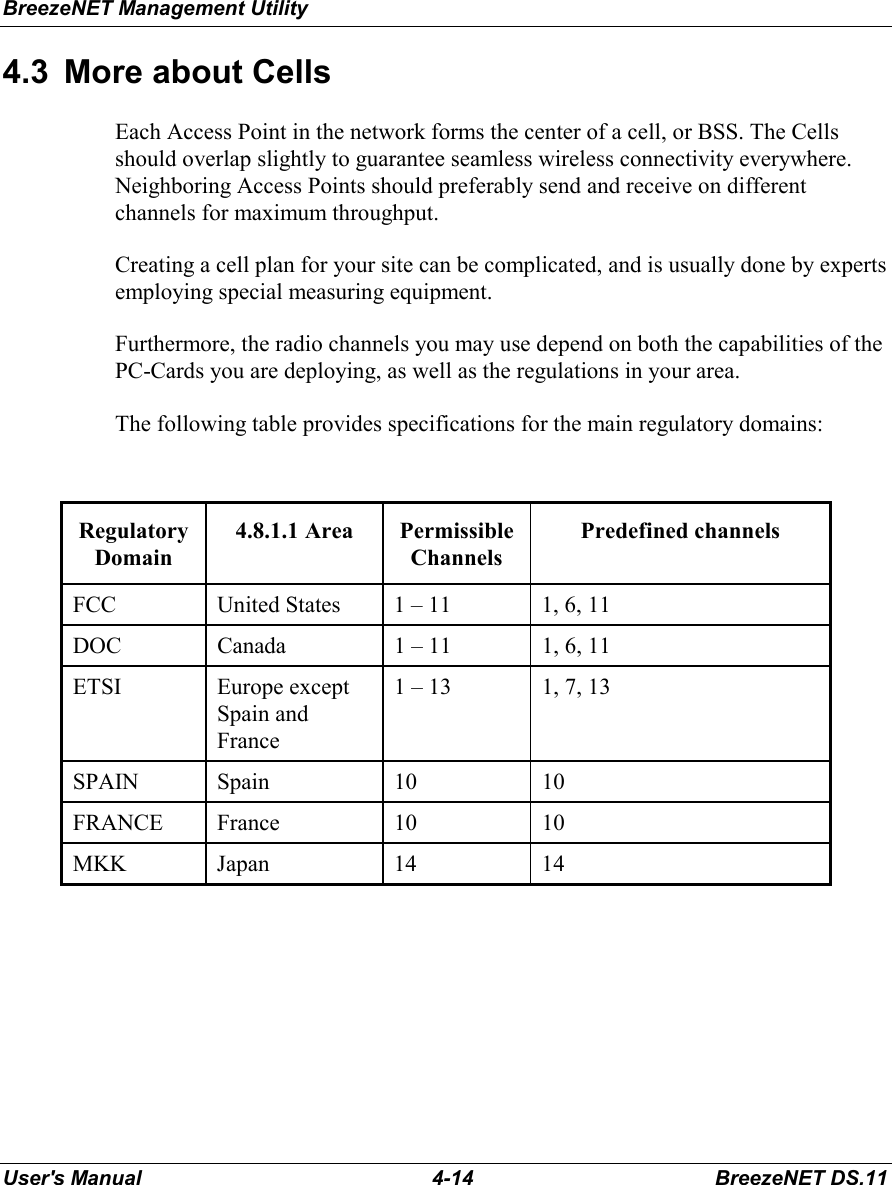
![Software DownLoad ProcedureBreezeNET PRO.11 Series 5-15 User’s Guide5. SOFTWARE DOWNLOAD PROCEDURE1. Set the unit's IP address, using the BreezeCOM Manager utility, and verify thatthe PC's IP address belongs to the same Subnet Mask as the unit.2. Ping the unit's IP address. Make sure that the Ping replies are being received.3. Use the TFTP utility on the PC:a) Syntax: TFTP [-i] destination host [PUT] source file [password]b) Example: TFTP -i 199.203.141.30 put ap1100.arm private Download will be completed within 1 minute, and a message of successful filetransfer will show on the screen.4. Click OK; the unit resets itself.5. Check the diagnostics LEDs, and use the BreezeNET Management utility tomake sure that the version number is correct.Note: Do not disconnect any cables or try to stop the process before downloading iscompleted.](https://usermanual.wiki/Alvarion-Technologies/DS11.Users-manual-for-outdoor-model-of-EUT/User-Guide-43501-Page-39.png)