Alvarion Technologies EXTR-50 BreezeMAX Extreme 5.4 Base Station User Manual Extreme BTS QIG
Alvarion Technologies Ltd. BreezeMAX Extreme 5.4 Base Station Extreme BTS QIG
Contents
- 1. user installation manual
- 2. Updated user manual Correspondance 39238
- 3. Professional Installer qualifications and Quick Installation guide
- 4. User manual 1
- 5. User manual 2
Professional Installer qualifications and Quick Installation guide

BreezeMAX Extreme Base Transceiver Station Quick Installation Guide
P/N 215790 - 1 - January 2011
This Quick Installation Guide is intended for experienced installers. For more information refer to the relevant sections in the
System Manual.
Packing List
Check that the package contains:
BTS
BTS (weight: 10.7 Kg.)
Mounting kit (for 1.5”-4” poles)
Sealing Gland Fastening Tool
Carrying hook
Mounting Kit
Carriage
T ilt bracket
Two Heavy duty metal clamps
4 x Threaded rods
10 x M8X20 screws
18 x M8 flat washers
8 x M8 nuts
14 x M8 spring washers
For poles larger than 4” – an additional kit containing 4 metal bands is required
GPS
One of the following options:
Basic GPS
28 dBi GPS antenna
3m cable
Pole mount bracket
Two metal bands
One Lightning Arrestor with 0.5m cable, including screws, washers, and spring washers (UNC10-32)
High Gain GPS
High gain (35 dBi) antenna
25m cable
Pole mount bracket
Two metal bands
Carriage mounting bracket
Two Lightning Arrestors with 0.5m cables, including screws, washers, and spring washers (UNC10-32)
NOTE: The lightning arrestors supplied within the GPS kit are not included in the warranty cover provided for the GPS
unit. Additional lightning arrestors can be ordered separately.
Additional Installation Requirements
Ethernet cable (Not applicable for 5 GHz units using PoE power supply option). Use a straight cable for connecting
directly to a PC’s NIC, and a crossed cable for connecting to a hub/switch etc.)
Po wer Supply:
PoE Power Supply with a Data and Power (indoor-outdoor) CAT5 cable (applicable only for 5 GHz units,
available in various lengths), or:
A 48V DC power source and a DC power source.
Antenna(s) and RF cable(s) (applicable for units without integral antennas)
Grounding cables with an appropriate termination
For wall mount installation - suitable securing means, e.g. dowels and screws (not supplied)
For GPS chaining, if applicable: Outdoor CAT5 cable(s)
General:
Mains plug adapter or termination plug ( For AC power supplies, if the power plug on the supplied AC power cord does
not fit local power outlets)
Portable PC with Ethernet card and Telnet software or configuration utility SW and a crossed Ethernet cable
Installation tools and materials, including appropriate means (e.g. a pole).
Equipment Positioning Guidelines
WARNING: ONLY experienced installation professionals who are familiar with local building and safety codes and,
wherever applicable, are licensed by the appropriate government regulatory authorities should install outdoor
units and antennas.
Failure to do so may void the equipment warranty and may expose the end user or Service Provider to legal
and financial liabilities. The manufacturer and its resellers or distributors are not liable for injury, damage or
regulation violations associated with the installation of Outdoor Units or antennas.
Select the optimal locations for the equipment using the following guidelines:
The unit can be either pole or wall mounted. Its location should enable easy access to the unit for installation and testing.
BreezeMAX Extreme Base Transceiver Station Quick Installation Guide
P/N 215790 - 2 - January 2011
All the installations options include a tilt bracket which supports Rotation: ±45° and Tilt: +7.5° to -10°
The higher the placement of the antenna, the better the achievable link quality.
The BTS should be installed as close as possible to the external antenna, if applicable (to ensure that the antenna's
characteristics are not affected the distance must be higher than 10 cm).
The indoor equipment should be installed as close as possible to the location where the indoor-to-outdoor cable enters
the building. The location of the indoor equipment should take into account its connection to a power outlet and the
customer’s equipment.
Installation Guidelines
NOTE: Ensure that outdoor units, antennas and supporting structures are properly installed to eliminate any physical
hazard to either people or property. Make sure that the installation of the BTS, antenna and cables is
performed in accordance with all relevant national and local building and safety codes. Even where grounding
is not mandatory according to applicable regulation and national codes, it is highly recommended to ensure
that the outdoor unit and the antenna pole (when using external antenna) are grounded and suitable lightning
protection devices are used so as to provide protection against voltage surges and static charges. In any
event, the supplier is not liable for any injury, damage or regulation violations associated with or caused by
installation, grounding or lightning protection.
It is the customer's responsibility to ensure that the TX power comply with the standards.
The BTS can be mounted on a pole using one of the following options:
Special clamps and threaded rods are supplied with each unit. There are two pairs of threaded holes on the back of the
carriage, enabling to use the special clamps for mounting the unit on poles up to 4” diameter.
Special grooves on the carriage enable the use of metal bands to secure the carriage to a pole larger than 4”.
NOTE: Mount the unit with the bottom panel, which includes the LED and connectors, facing downward. Note the
direction arrows (UP) on the sides of the BTS
CAUTION: The weight of BTS is 10.7 Kg and the weight of the Pole Mounting Kit is approximately 5 kg. Be sure to plan
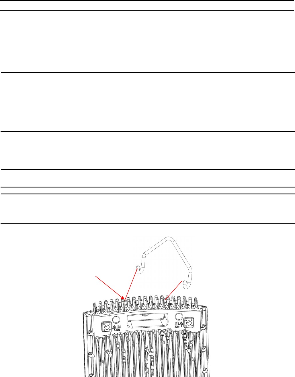
the installation accordingly. It is recommended to use the supplied carrying hook (see Figure 1) and a
harness to lift the units.
Install the unit using the supplied kit only.
Figure 1: Carrying Hook
Carrying holes
BreezeMAX Extreme Base Transceiver Station Quick Installation Guide
P/N 215790 - 3 - January 2011
Installing the BTS
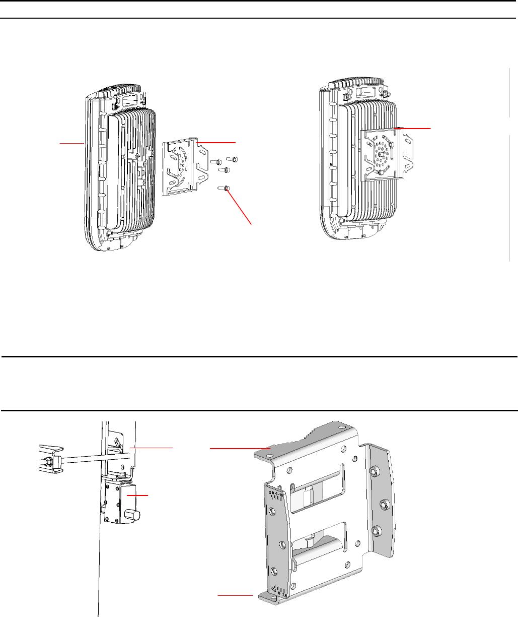
1. Assemble the tilt bracket on the BTS and fasten its M8 screws. Apply torque of 80 [Lib*In] = 9 [N*m]
Figure 2: Assembling the Tilt Bracket on the BTS
Carrying grooves
BTS Tilt bracket
M8X20 screws
2. Install a lightning arrestor (part of the GPS kit) at the designated location at the bottom of the carriage.
3. Connect one end of the 0.5m cable to the lightning arrestor and the other end to the GPS ANT connector on the BTS.
NOTE: Some units are supplied with a separate pole-mounting bracket for the lightning arrestor. Instead of attaching
the lightning arrestor to the carriage, install this bracket on the pole as close to the BTS as possible, allowing
connecting the lightning arrestor to the GPS connector on the BTS.
The lightning arrestors supplied within the GPS kit are not included in the warranty cover provided for the GPS
unit. Additional lightning arrestors can be ordered separately.
Figure 3: Assembling the Lightning Arrestor on the Carriage
Carriage
Lightning arrestor
Hole for lightning arrestor
4. Do one of the following:
For poles up to 4” - Thread the four rods through the carriage. Insert the threaded rods with the grooves
pointing outward, as these grooves enable you to use a screwdriver to fasten the rods to the unit. Attach the
carriage and the clamps to the pole and tighten on both sides using the supplied washers, spring washers
and nuts. Apply torque of 80 [Lib*In] = 9 [N*m].
For poles larger than 4” - Thread the four metal bands through the grooves on the carriage and fasten.
For wall mount installation - mark the exact location of the holes to drill on the wall. Drill the holes, and use
four metal dowels and screws to affix the carriage to the wall.
BreezeMAX Extreme Base Transceiver Station Quick Installation Guide
P/N 215790 - 4 - January 2011
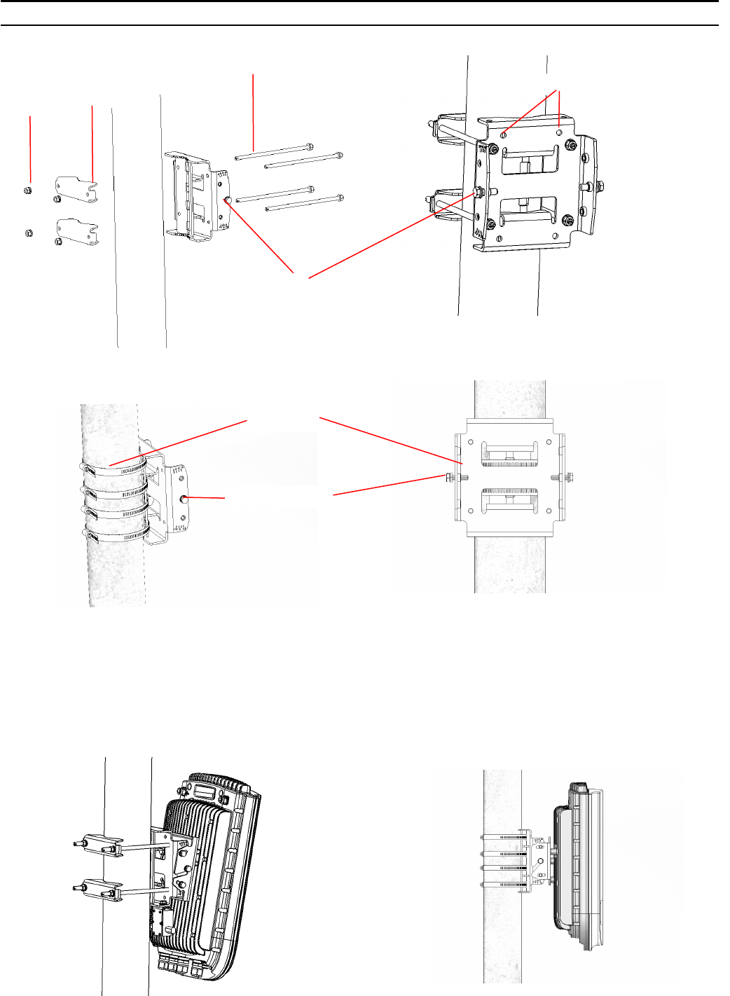
Figure 4: Assembling the Carriage on 1.5”-4” Poles Using Clamps
Figure 5: Assembling the Carriage on Poles Larger than 4” Using Metal Bands
Nuts,
washers
and spring
washers Clamps
Rods
Holes for wall mount (x4)
Tilt control screw
Metal bands
Tilt control screw
5. Insert the Tilt Control screws into the middle-side hole of the carriage on both sides.
6. Hang the BTS with the tilt bracket on the Tilt-control screws of the BTS carriage.
7. Attach and fasten all the screws at both sides of the BTS carriage. Do not over tighten.
8. If required, slightly release the tilt bracket screws to enable rotation and the Tilt Control screws to enable tilting; adjust the
BTS position and tighten the screws. Apply torques of 45 [Lib*In.] = 5 [N*m] to the M6 Tilt-control screws, and
80 [Lib*In] = 9 [N*m] to the M8 screws.
Figure 6: BTS Mounted on a 1.5''-4'' Pole (with Clamps), and on Pole Larger than 4” (with Metal Bands)
BreezeMAX Extreme Base Transceiver Station Quick Installation Guide
P/N 215790 - 5 - January 2011
Installing the GPS
Basic GPS
1. Place the bracket on a flat surface and thread the GPS antenna through the hole at the top of the bracket. Hand-tighten the
fastening nut.
2. Connect one end of the 0.5 m cable to the lightning arrestor and the other end to the GPS ANT connector on the BTS.
3. Connect one end of the GPS 3m cable to the lightning arrestor, and the other end to the GPS antenna.
4. Use the supplied metal bands to assemble the bracket on a pole.
5. Fix the cable onto the pole using plastic strips.
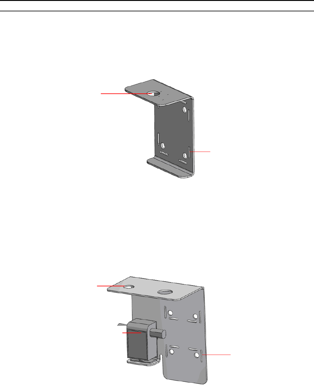
Figure 7: Bracket for Basic GPS
Hole for GPS
antenna
Holes for
metal bands
High-Gain GPS
1. Place the bracket on a flat surface and thread the GPS antenna through the 3/4" hole of the bracket. Hand-tighten the
fastening nut.
2. If you use a High-Gain GPS antenna with a cable longer than 3m, assemble the lightning arrestor on the bracket, with the
screws facing the bracket.
3. Connect one end of the 0.5m cable to the lightning arrestor and the other end to the GPS antenna.
4. Use the 25m GPS cable to connect the lightning arrestor on the GPS bracket to the second lightning arrestor installed near
the BTS. Connect this second lightning arrestor to the GPS ANT connector on the BTS.
5. Hand-tighten the connector on the interface cable using the locking-ring to secure the connection.
6. Use the supplied metal bands to assemble the bracket on a pole.
7. Fix the cable onto the pole using a plastic strip.
Figure 8: Bracket for High-gain GPS
Hole for High-gain
GPS antenna
Lightning arrestor
Holes for
metal bands
Indoor Power Supply Installation
The BTS is powered from a 48V DC power source. The following indoor AC/DC power supplies may be used to support the
different power requirements of the various BTS units:
A PoE AC/DC power supply that can supply DC power over the Ethernet to the BTS via the DATA DC IN/OUT
connection. This option is available in the 5 GHz BTS units only.
A 48V DC power source that connects to the 48V connector of the BTS. When using this power supply option, DC power
is available also on the DATA DC IN/OUT connector, allowing power feeding to a backhauling CPE.
Both units can be wall mounted or placed on the desktop.
BreezeMAX Extreme Base Transceiver Station Quick Installation Guide
P/N 215790 - 6 - January 2011
CAUTION: Do not connect two power sources (PoE and DC input) simultaneously.
Connecting the Cables to the BTS
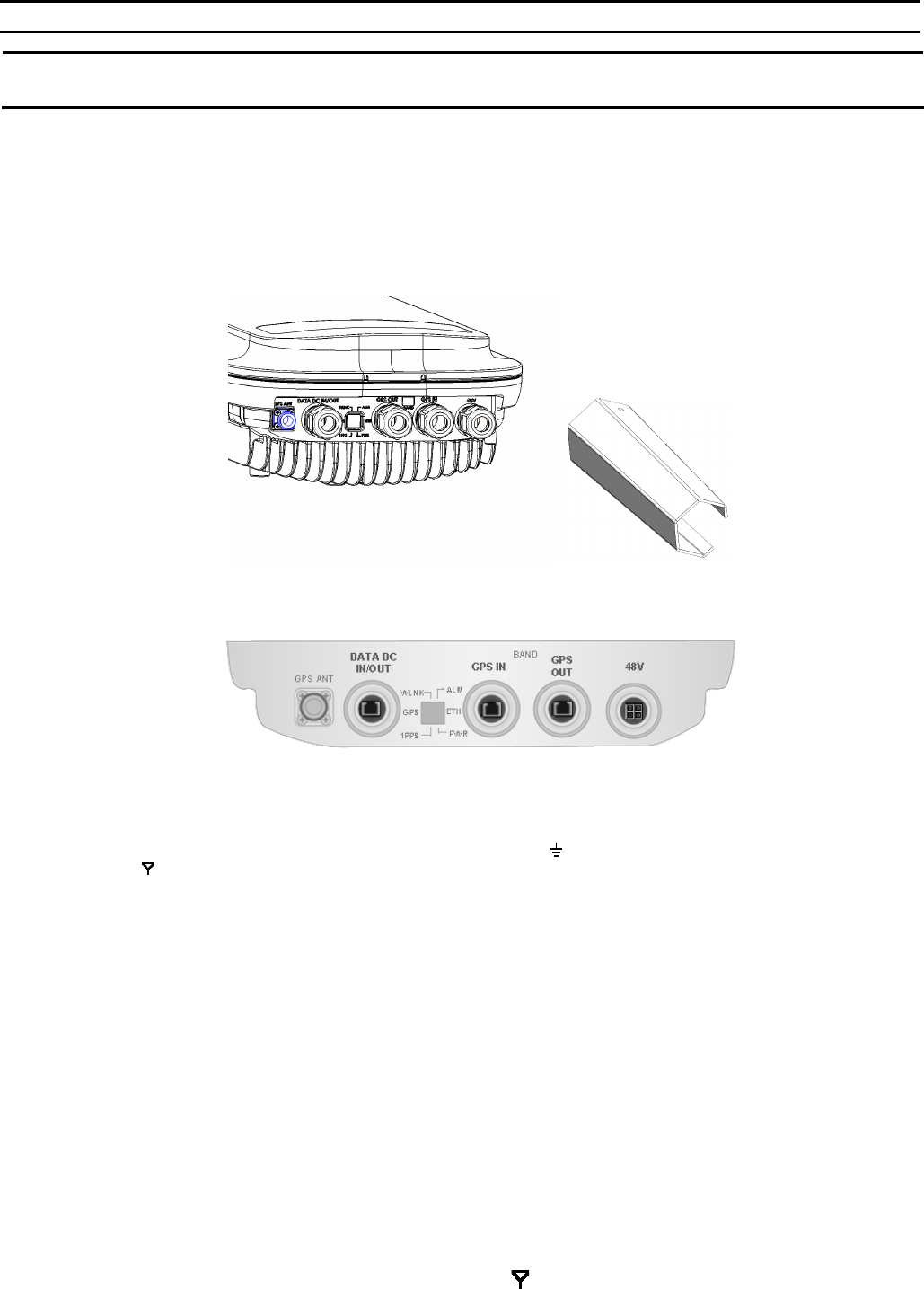
The BreezeMAX Extreme is provided with sealing glands on all the cable connectors. The DATA/DC IN/OUT, and GPS IN/OUT
cables are to be connected to the BTS by inserting the cable connector through the sealing gland. The DC power cable is
supplied with a sealing gland that should replace the existing sealing gland provided with the BTS. For the GPS ANT connector,
a weather-proof metal cap seals the connection. If this connector is not used, do not remove the metal cap. In case there is only
a rubber cap on this connector, use additional sealing methods to protect this connection.
A dedicated tool is supplied for fastening the sealing glands.
Figure 9: BTS with Sealing Gland and Gland Fastening Tool
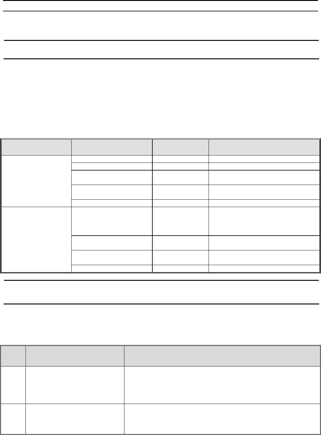
Figure 10: BTS Connections (Bottom View)
Grounding Cable
Connect a grounding cable between the ground terminal of the BTS (marked ) and a good ground connection. Connect the RF
connector (marked ) to the antenna. The RF connectors should be properly sealed to protect against rain and moisture.
Data/PoE Cable
1. Remove the DATA DC IN/OUT sealing gland from the BTS.
2. Open the sealing gland and thread the cable through the gland's nut.
3. Carefully insert the cable with the already assembled RJ-45 connector through the sealing gland.
4. Connect the cable to the DATA connection on the BTS.
5. Return the sealing gland. Use the dedicated tool to fasten it.
6. Use the dedicated tool to fasten nut on the sealing gland body.
7. Connect the other end of the cable to one of the following:
If you are using PoE (for 5 GHz units only) - to the PoE AC/DC power supply RJ-45 connector (labeled as
Radio). Connect the Ethernet port of the PoE PS to the backhauling equipment using a standard Ethernet
cable. Connect the PoE PS to the 110/220 VAC mains. The combined lengths of the Ethernet cables should
not exceed 100m.
If you are not using PoE – directly to the backhauling equipment.
DC Power Cable (not applicable if using PoE)
1. Remove the existing gland from the 48V connection on the BTS
2. Attach the DC power cable with the already assembled sealing gland to the 48V connection on the BTS.
3. Separate the sealing gland’s nut from the gland body.
4. Use the dedicated tool to fasten the gland to the BTS.
5. Use the dedicated tool to fasten the sealing gland's nut on the gland body.
6. Connect the other end of the power cable to the 48V DC power source.
External Antenna Cable
1. Connect one end of the coaxial RF cable to the connector (marked ) located on the rear panel of the unit.
2. Connect the other end of the RF cable to the antenna.
3. The RF connectors should be properly sealed to protect against rain and moisture.
BreezeMAX Extreme Base Transceiver Station Quick Installation Guide
P/N 215790 - 7 - January 2011
Configuring BTS Basic Parameters
Initial configuration can be performed either via Telnet (the Monitor application) or AlvariCRAFT.
NOTE: AlvariCRAFT can be used only if the Authorized Managers list in the BTS is either empty (default) or includes the
IP address of the AlvariCRAFT station.
1. Connect a PC to the Ethernet port, using a crossed cable. The default IP address is 1.1.1.23.
2. If you use Telnet for initial configuration, run the Telnet program. Select your permitted access level and enter your
password (the default Installer password is “installer”).
3. Access the following menus and configure the basic parameters required to enable remote management of the BTS:
BTS connectivity menu: 1 - BTS --> 3 - Configuration --> 3 – Connectivity – to set IP parameters
Authorized Managers menu: 1 - BTS --> 3 - Configuration --> 4 - Authorized Managers – to set management
station parameters
In many installations, most of these parameters should not be changed from their default values. The following list includes the
basic parameters and their default values:
Basic Parameters
Management Option Parameter Default Value Comment
IP Address 1.1.1.23
Subnet Mask 255.0.0.0
Default Gateway 0.0.0.0 The Default Gateway must be in the
subnet of the IP Address.
VLAN ID 4096 (No VLAN) Available values:1 to 4094, or
4096/blank for No VLAN (untagged)
BTS-Connectivity
VLAN Priority No VLAN Priority Available values: 0 to 7
Manager IP Address The IP Address of an existing
Manager cannot be updated (to
change it you must first delete the
Manager)
Read Community public Valid Community strings: 1 to 32
printable characters, case sensitive.
Write Community private Valid Community strings: 1 to 32
printable characters, case sensitive.
Authorized Managers
(per manager)
Traps Distribution Enabled Enable
NOTE: If no Authorized Manager is defined in the device, it can be managed using SNMP by any station. If at least one
Authorized Manager is defined, the device can be managed only by a station whose parameters match a defined
Authorized Manager.
Operation Verification
To verify the correct operation of the BTS (including GPS), examine the LED indicators located at the bottom panel of the unit:
BTS LEDs
Name Description Functionality
PWR Power indication Off - Power failure
Green - Power to ODU is OK, internal 3.3 VDC power supply is
OK.
ALR IDU-ODU communication and
synthesizer status indication Off -Built-in-test passed successfully.
Red - Critical failure.

BreezeMAX Extreme Base Transceiver Station Quick Installation Guide
P/N 215790 - 8 - January 2011
Name Description Functionality
ETH Ethernet link status Off - No Ethernet connection
Green - Lights when the backhaul Ethernet is connected and
blinks 500ms on and 500ms off when data traffic appears on the
Ethernet link.
WLNK Wireless link status Off - No wireless link (no MS is registered)
Green - Blinking when the wireless link is working (transmitting),
indicating that there is at least one registered MS being served
by the unit.
GPS GPS synchronization status Off - GPS is not synchronized (see below) or not installed.
Green - On once the GPS is reporting on reception of at least 4
satellites (initial synchronization).
Blinking Green - (0.5 Sec on, 0.5 Sec off) the number of received
satellites decreased from 4 (or more) to 3 or 2 satellites.
1PPS 1PPS clock status Master Unit
Off - GPS is not installed.
Green - 1PPS clock is supplied by GPS.
Slave Unit:
Off - External 1PPS is not supplied.
Blinking Green - blinking at the 1PPS rate when external 1PPS
clock is supplied.
* All LEDs are turned on upon power up and turn off after successful completion of the built-in-test.
FCC Radio Frequency Interference Statement
The Base Transceiver Station (BTS) equipment has been tested and found to comply with the limits for a class A digital device,
pursuant to ETSI EN 301 489-1 rules and Part 15 of the FCC Rules. These limits are designed to provide reasonable protection
against harmful interference when the equipment is operated in commercial, business and industrial environments. This
equipment generates, uses, and can radiate radio frequency energy and, if not installed and used in accordance with the
instruction manual, may cause harmful interference to radio communications. Operation of this equipment in a residential area
is likely to cause harmful interference in which case the user will be required to correct the interference at the user's own
expense.
FCC Radiation Hazard Warning
To comply with FCC RF exposure requirements in Section 1.1307 and 2.1091 of FCC Rules, the antenna used for this
transmitter must be fixed-mounted on outdoor permanent structures with a separation distance of at least 2 meter from all
persons.
R&TTE Compliance Statement
This equipment complies with the appropriate essential requirements of Article 3 of the R&TTE Directive 1999/5/EC.
Disposal of Electronic and Electrical Waste
Disposal of Electronic and Electrical Waste
Pursuant to the WEEE EU Directive electronic and electrical waste must not be disposed of with
unsorted waste. Please contact your local recycling authority for disposal of this product.